

Danfoss VVX Compact 28 Fact sheet
Fact sheet
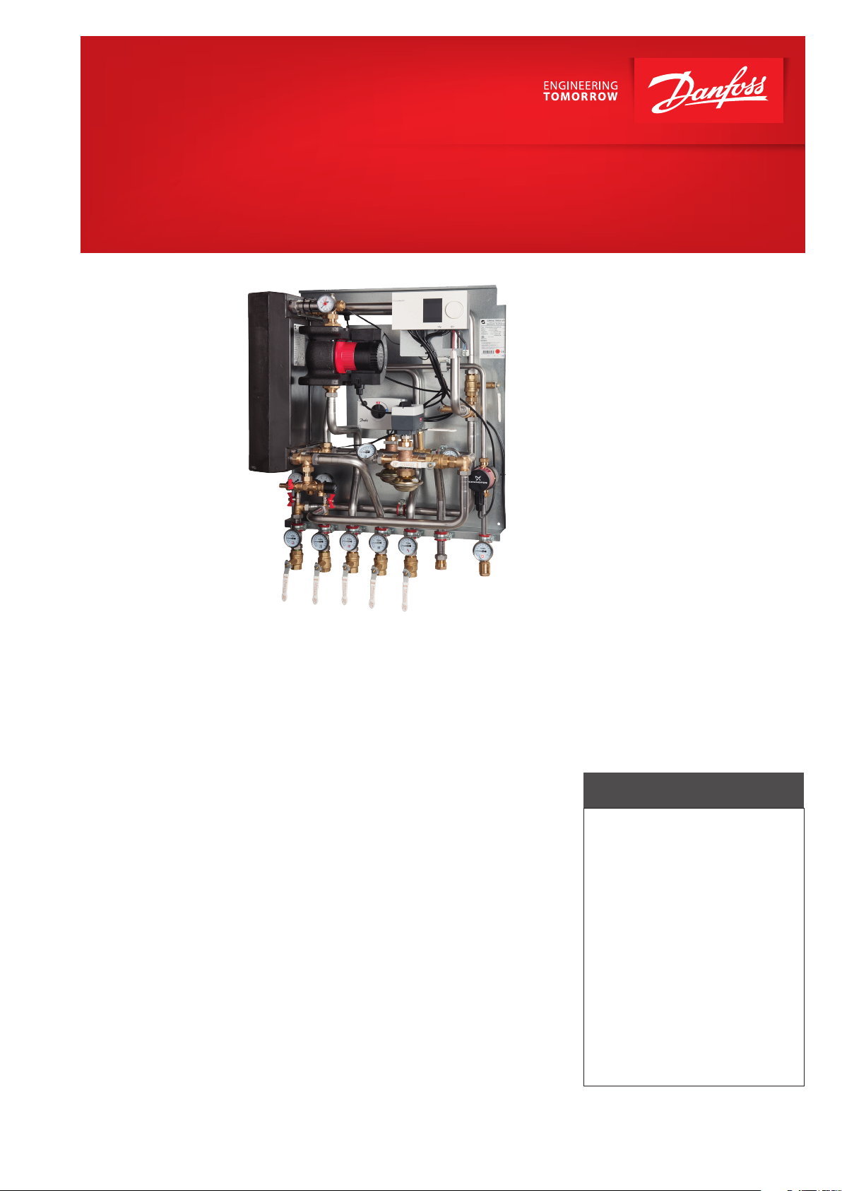
Termix VVX Compact 28
Indirect substation for buildings with up to 25 apartments
Application
The Termix VVX Compact 28 is acomplete solution for hot water and space
heating with optimal safety, ecient
energy transfer, service-friendly construction and a compact design. The
substation is applicable, if a heat exchanger is required or on a conversion to district heating, where the
existing equipment is unsuitable for
direct connection.
District heating (DH)
The district heating circuit is prefabricated with a ow controller with integrated control valve as well as thermometers and ball valves.
Heating (HE)
The heating circuit consists of a plate
heat exchanger, safety valve, manometer, thermometers, ball valves,
drain valve, air valve and circulation
pump. The heating circuit is controlled with an electronic controller
with an outdoor temperature sensor.
Domestic hot water (DHW)
The domestic hot water is prepared
in the plate heat exchanger and the
temperature is regulated with an
electronic controller. The efficient
heat exchanger offers exceptionally good heat extraction with high
output. No readjustment of the
DHW temperature is required after
installation and initial setting of the
controls. The electronic control automatically retains the comfort temperature of the hot water, even when
the heating system is in reduced
operation during summer or if the
district heating plant changes operating parameters between summer
and winter. An integrated circulation
pump for DHW is installed.
Options
Termix VVX Compact 28 can be delivered with white-lacquered steel
cover and lling line between primary
and secondary side.
Construction
All pipes are made of stainless steel.
The connections are made by nuts
and gaskets.
FEATURES AND BENEFITS
• Substation for apartment buildings
• Thermostatic or electronic control
of heating and DHW temperature
• Capacity: 150 kW heating, 150 kW DHW
• DHW in sufficient quantity
• Operates independent of differential
pressure and flow temperature
• Minimum space required
for installation
• Pipes and plate heat exchanger
made of stainless steel
• Minimized risk of lime scale
and bacteria formation
www.heating.danfoss.com
Danfoss can accept no responsibility for possible errors in catalogues, brochures and other printed material. Danfoss reserves the right to alter its products without notice. This also applies to products
already on order provided that such alterations can be made without subsequential changes being necessary eady agreed.
All trademarks in this material are property of the respective companies. Danfoss and the Danfoss logotype are trademarks of Danfoss A/S. All rights reserved.
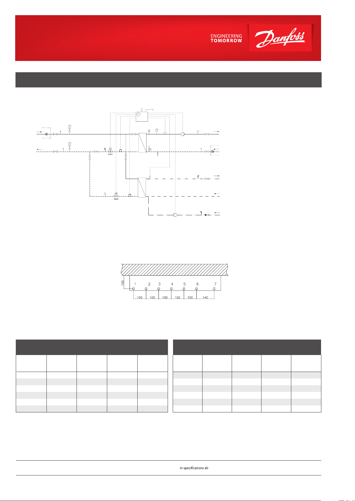
CIRCUIT DIAGRAM - EXAMPLE
1 18
25 bar
25
25 bar
25
1
DH
supply
DH
return
24
9 1 18
A Heat exchanger HE
16
230 V
B Heat exchanger DHW
F Electronic controller
1 Ball valve
F
4 bar
48
1 1
27
1
19
30
1
26
4
20
A
10 18
19
18
HE
supply
24
9
1
HE
return
2 Non-return valve
4 Safety valve
9 Strainer
10 Circulation pump
11 DHW pump
16 Outdoor sensor
18 Thermometer
19 Surface sensor
20 Filling/drain valve
40
18
27
19
30
B
1
18
DHW
DCW
24 Delivered loose with unit
25 Manometer with ball valve
26 Manometer
27 Actuator
30 Flow control w. control valve
48 Air escape, manual
Technical parameters:
Nominal pressure: PN 16
DH supply temperature: T
DCW static pressure: P
Brazing material (HEX): Copper
= 120 °C
max
= 0,5 bar
min
Weight: approx. 75 kg
Dimensions (mm)
Without cover: H 970 × W 750 × D 440
With cover: H 970 × W 800 × D 522
Electrical supply: 230 V AC
DHW: CAPACIT Y EXAM PLES, 10 °C / 50 °C
DHW
capacity
[kW]
100 70 22 50 2150
110 70 22 50 2365
120 70 22 50 2580
130 70 22 50 2795
140 70 22 50 3010
150 70 22 50 3225
Supply flow
primary
[°C]
Return flow
primary
[°C]
Pressure loss
primary
[kpa]
Flow rate
secondary
[l/h]
18 211
Circ.
Connections:
1. District heating (DH) supply
wall
2. District heating (DH) return
3. Heating (HE) supply
4. Heating (HE) return
5. Domestic hot water (DHW)
6. Domestic cold water (DCW)
7. DHW circulation (Circ.)
Connections sizes:
DH + HE + DCW + DHW: G 1” (int. thread)
Circulation: G 3/4” (int. thread)
Options:
• Cover
• Filling line
HEATING: CAPACITY EXAMPLES
Heating
capacity
[kW]
110 90 / 45 40 / 70 50 3153
120 90 / 45 40 / 70 50 3440
140 90 / 45 40 / 70 50 4013
150 90 / 45 40 / 70 50 4300
Heating circuit
primary
[°C]
Heating circuit
secondary
[°C]
Pressure loss
primary
[kpa]
secondary
70 90 / 45 40 / 70 50 2007
90 90 / 45 40 / 70 50 2580
Flow rate
[l/h]
Danfoss Randall Ltd . • Unit A4, Centre Point Business Park, Oak Road • Dublin 12 • Ireland
Tel.: +353 1800 930 243 • Fax: +353 1800 556 691 • districtheating@danfoss.com • www.dh.danfoss.com
© Danfoss | DHS-SRMT/ PL | 2016. 02
VL.EH.K3.02
 Loading...