

Page 1

■ Contents
VLT®2800 Series
Introduction to VLT 2800
Software version ...................................................................................................... 4
High voltage warning ............................................................................................... 5
These rules concern your safety ............................................................................... 5
Warning against unintended start ............................................................................. 5
Technology .............................................................................................................. 6
CE labelling ............................................................................................................. 8
Modbus RTU ......................................................................................................... 11
Motor coils ............................................................................................................. 12
EMC filter for long motor cables ............................................................................ 16
Ordering numbers for VLT 2800 200-240 V .................................................. ........ 17
Ordering numbers for VLT 2800 380-480V ............................................................ 19
Order form ............................................................................................................. 21
PC software ........................................................................................................... 22
PC Software tools .................................................................................................. 22
Accessories for the VLT 2800 ........................................................................ ........ 23
Control unit ............................................................................................................ 30
Manual initialisation ................................................................................................. 30
Hand Auto ............................................................................................................. 31
Automatic motor tuning ......................................................................................... 32
The LCP 2 Control unit, option .............................................................................. 33
Parameter selection ............................................................................................... 36
............................................................................... 4
Installation ......................................................................................................... 38
Mechanical dimensions .......................................................................................... 38
Mechanical installation ........................................................................................... 42
General information about electrical installation ...................................................... 43
EMC-correct electrical installation .......................................................................... 44
Earthing of screened/armoured control cables ....................................................... 46
Diagram ................................................................................................................. 47
Electrical installation ............................................................................................... 48
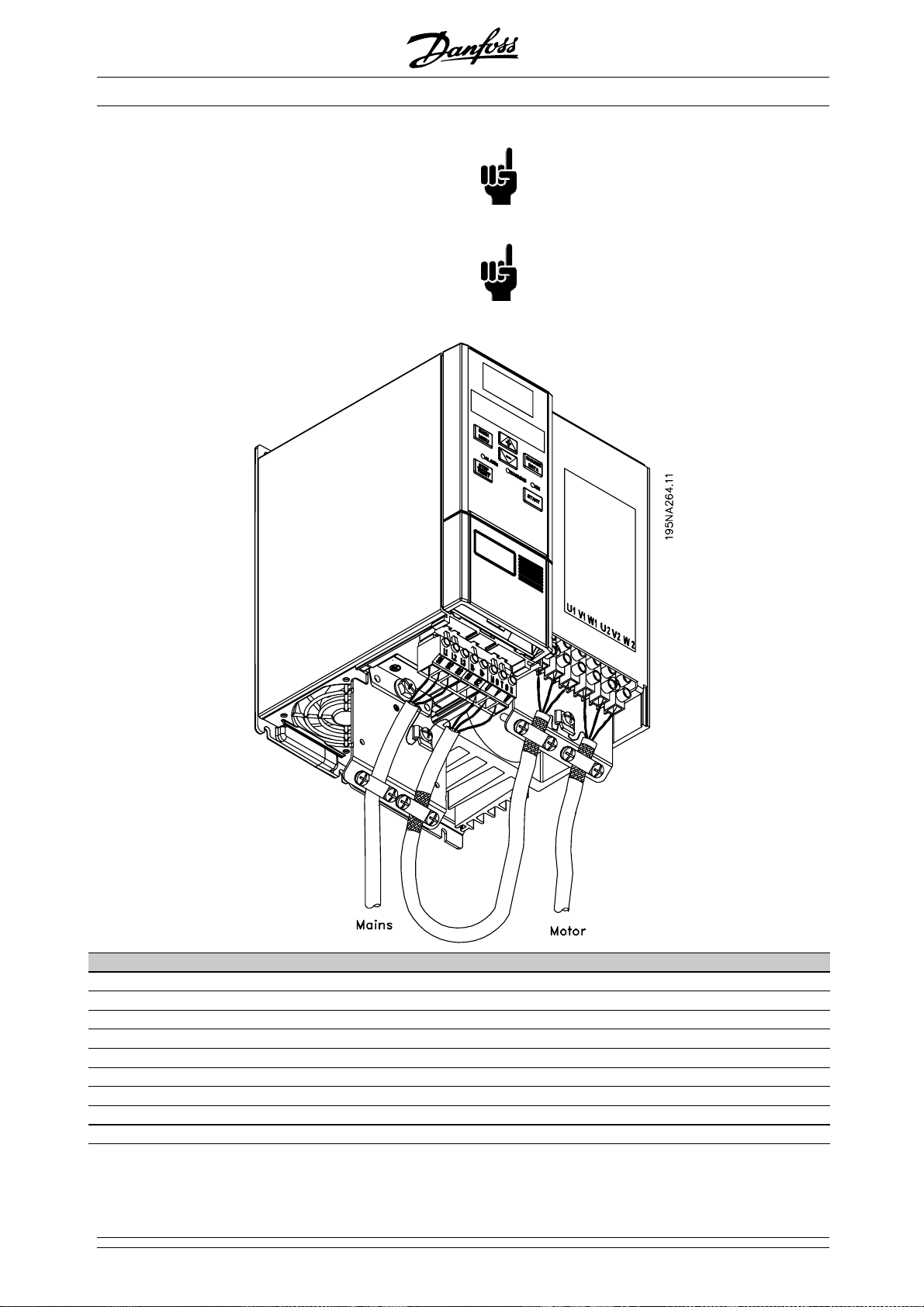
Safety clamp .......................................................................................................... 50
Pre-fuses ....................................................................................................... ......... 50
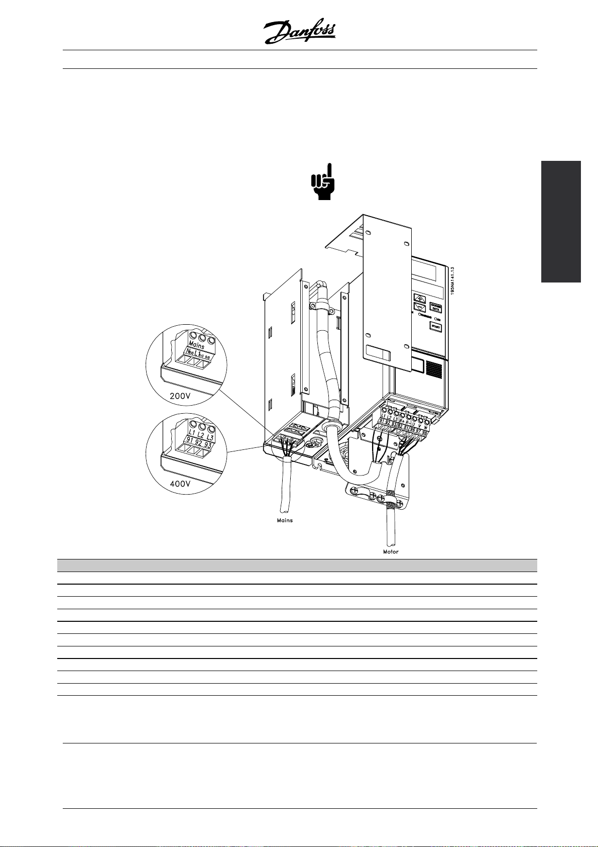
Mains connection ................................................................................................... 50
Motor connection ................................................................................................... 50
RFI switch .............................................................................................................. 51
Direction of motor rotation ..................................................................................... 51
Parallel connection of motors ................................................................................. 51
Motor cables ................................................................................................. ......... 52
Motor thermal protection ....................................................................................... 52
Brake connection ................................................................................................... 52
Earth connection .................................................................................................... 52
Load sharing .......................................................................................................... 53
Tightening Torque, Power Terminals ...................................................................... 53
Control of mechanical brake .................................................................................. 53
Access to control terminals .................................................................................... 53
Electrical installation, control cables ....................................................................... 54
Tightening torques, control cables .......................................................................... 55
Electrical installation, control terminals ................................................................... 55
Relay connection ................................................................................................... 55
VLT Software Dialog .............................................................................................. 55
MG.28.E9.02 - VLT is a registered Danfoss trademark
1
Page 2

VLT®2800 Series
Connection examples ............................................................................................ 56
Use of internal PID-controller - closed loop process control .................................. 58
Programming .............................. ...................................................................... 60
Operation & Display ............................................................................................... 60
Setup configuration ................................................................................................ 60
Load and Motor ..................................................................................................... 68
DC Braking ............................................................................................................ 73
References & Limits ............................................................................................... 78
Handling of references ........................................................................................... 78
Reference function ................................................................................................. 82
Inputs and outputs ................................................................................................. 87
Special functions .................................................................................................... 97
PID functions ....................................................................................................... 100
Handling of feedback ........................................................................................... 101
Serial communication for VLT 2800 ..................................................................... 108
Control Word according to FC protocol ............................................................... 112
Status Word according to FC Profile .................................................................... 114
Control word according to Fieldbus Profile .......................................................... 115
Status word according to Profidrive protocol ....................................................... 116
Serial communication ........................ ................................................................... 119
Technical functions .............................................................................................. 127
All about VLT 2800 ....................................................................................... 131
Special conditions ................................................................................................ 131
Galvanic Isolation (PELV) ...................................................................................... 131
Earth leakage current and RCD relays ................................................................. 131
Extreme operating conditions ............................................................................... 131
dU/dt on motor .................................................................................................... 132
Switching on the input ......................................................................................... 132
Acoustic noise ...................................................................................................... 132
Temperature-dependent switch frequency ........................................................... 133
Derating for air pressure ...................................................................................... 133
Derating for running at low speed ........................................................................ 133
Derating for long motor cables ............................................................................. 133
Derating for high switching frequency - VLT 2800 ................................................ 133
Vibration and shock ............................................................................................. 134
Air humidity .......................................................................................................... 134
UL Standard ........................................................................................................ 134
Efficiency .............................................................................................................. 134
Mains supply interference/harmonics .............................................................. ..... 134
Power factor ........................................................................................................ 135
Generic EMC standards/product standards ......................................................... 136
EMC emission .................................. .................................................................... 136
EMC Immunity ...................................................................................................... 138
Harmonic Current Emission .................................................................................. 139
Aggressive environments ...................................................................................... 139
Display readout .................................................................................................... 140
Warnings/alarm messages ................................................................................... 140
Warning words, extended status words and Alarmwords ................................... 145
General technical data ......................................................................................... 146
Technical data, mains supply 1 x 220 - 240 V/3 x 200-240V .............................. 150
Technical data, mains supply 3 x 380 - 480 V ..................................................... 151
Available literature ................................................................................................. 152
2
MG.28.E9.02 - VLT is a registered Danfoss trademark
Page 3

VLT®2800 Series
Supplied with the unit ........................................................................................... 152
Index .................................................................................................................... 160
MG.28.E9.02 - VLT is a registered Danfoss trademark
3
Page 4
VLT®2800 Series
VLT 2800 Series
Design Guide
Software version: 2.8x
This design guide can be used for all VLT 2800 Series frequency converters with software version 2.8x.
The software version number can be seen from parameter
640; Software version no.
195NA021.19
NB!:
This symbol indicates something that should
be noted by the reader.
Indicates a general warning.
This symbol indicates a warning
of high voltage.
4
MG.28.E9.02 - VLT is a registered Danfoss trademark
Page 5

VLT®2800 Series
■High voltage warning
The voltage of the frequency converter
is dangerous whenever the converter
is connected to mains. Incorrect fitting
of the motor or frequency converter may cause
damage to the equipment, serious injury or death.
Consequently, it is essential to com ply with the
instructions in this manual as well as local and
national rules and safety regulations.
■These rules concern your safety
1. The frequency converter must be disconnected
from the mains if repair work is to be carried
out. Check that the mains supply has been
disconnected and that the prescribed time has
passed before removing motor and mains plugs.
2. The [STOP/RESET] key on the control panel of
the frequency converter
the equipment from mains and is thus n
to be used as a safety switch.
3. The unit must be properly connected to the
earth, the user must be protected against the
supply voltage and the motor must be protected
against overloading pursuant to prevailing
national and local regulations.
4. The earth leakage currents are higher than 3.5 mA.
5. Protection against motor overload is not included
in the factory setting. If this function is required,
set parameter 128 Motor thermal protection to
data value ETR trip or data value ETR warning.For
the North American market: The ETR functions
provide overload protection of the motor, class
20, in accordance with N EC.
6. Do n
7. Note that the frequency converter has more voltage
ot remove the plugs for the motor - and mains
supply while the frequency converter is connected
to mains. Check that the mains supply has been
disconnected and that the prescribed time has
passed before removing motor and mains plugs.
inputs than L1, L2 and L3 when the DC bus
terminals are used. Check that all voltage inputs
are disconnected and that the prescribed time has
passed before repair work is commenced.
does not disconnect
ot
ensure that no unintended start occurs,
stop functions are not sufficient.
2. While parameters are being changed, the
motor may start. Consequently, t
[STOP/RESET] must always be activated, following
which data can be modified.
3. A motor that has been stopped may start if faults
occur in the electronics of the frequency converter,
or if a temporary overload or a f ault in the supply
mains or the motor connection ceases.
■Use on isolated mains
See section RFI Switch regarding use on isolated mains.
It is important to follow the recommendations
regarding installation on IT-mains, since sufficient
protection of the complete installation must be
observed. Not taking care using relevant monitoring
devices for IT-mains may result in damage.
he stop key
these
2800
Introduction to VLT
■Warning against unintended start
1. The motor can be brought to a stop by
means of digital commands, bus commands,
references or a local stop, while the frequency
converter is connected to mains. If personal
safety considerations make it necessary to
MG.28.E9.02 - VLT is a registered Danfoss trademark
5
Page 6
■Technology
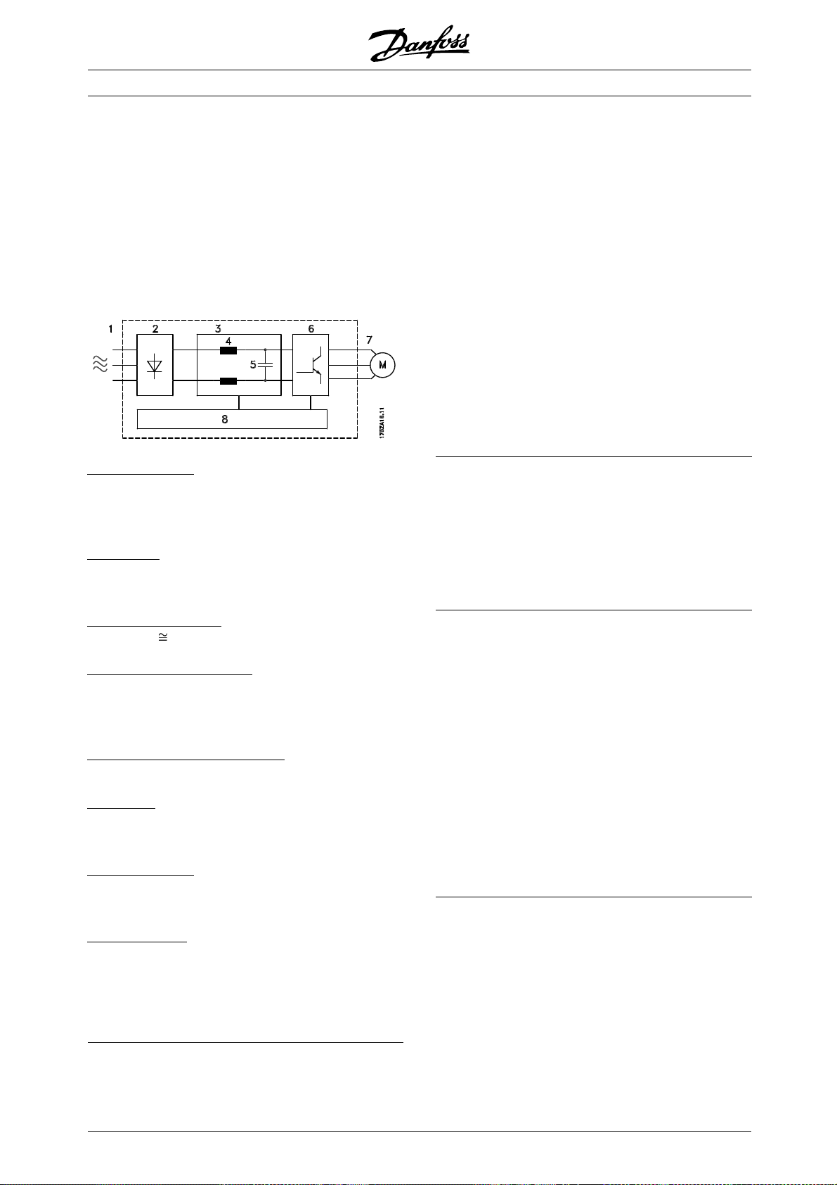
■Control principle
A frequency converter rectifies AC voltage from
the mains supply into DC voltage, following which
it changes this v oltage to an AC voltage with
variable amplitude and frequency.
The motor thus receives a variable voltage and
frequency, which enables infinitely variable speed
control of three-phase, standard AC motors.
1. Mains voltage
1 x 220 - 240 V AC, 50 / 60 Hz
3 x 200 - 240 V AC, 50 / 60 Hz
3 x 380 - 480 V AC, 50 / 60 Hz
. Rectifier
2
Three-phase rectifier bridge which rectifies AC
voltage into DC voltage.
VLT®2800 Series
■VLT 2800 control principle
A frequency converter is an electronic unit which is able
to infinitely vari ab ly control the rpm of an AC motor.
The frequency converter governs the motor speed
by converting the regular voltage and frequency from
mains, e.g. 400 V / 50 Hz, into variable magnitudes.
Today the frequency converter controlled AC motor is
a natural part of all types of automated plan ts.
The frequency converter has an inverter control system
called VVC (Voltage Vector Control). VVC controls
an induction motor by energizing with a variable
frequency and a voltage suitable for it. If the motor
load changes, so do its energizing and speed. That
is why the motor current is measured on an ongoing
basis, and a motor model is used to calculate the
actual voltage requirement and slip o f the motor.
■Programmable inputs and outputs in four Setups
In the frequency converter is possible to program the
different control inputs and signal outputs and to select
four different user-defined Setups for most parameters.
It is easy for the user to p rogram the required functions
on the control panel or via serial c ommunication.
3
. Intermediate circuit
DC voltage √2 x mains voltage [V].
4
. Intermediate circuit coils
Evens out the intermediate circuit current and
limits the load on mains and components (mains
transformer, cables, fuses and contactors).
. Intermediate circuit condenser
5
Evens out the intermediate circuit voltage.
6
. Inverter
Converts DC voltage into a variable AC voltage
withavariablefrequency.
. Motor voltage
7
Variable AC voltage d e pe nding on supply voltage.
Variable frequency: 0.2 - 132 / 1 - 1000 Hz.
8
. Control card
Here is the computer that controls the inverter
which generates the pulse pattern by which
the DC voltage is converted into variable AC
voltage with a variable frequency.
■Mains protector
The frequency converter is protected against the
transients that occur on the mains sometimes, e.g.
if coupling with a phase compensation system, or
if fuses blow when lightning strikes.
Rated motor voltage and full torque can be maintained
down to approx. 10% undervoltage in the mains supply.
As all 400 V units in the VLT 2800 Series have
intermediate circuit coils, there is only a low amount
of harmonic mains supply interference. This gives
a good power factor (lower peak current), which
reduces the load on the mains installation.
■Frequency converter protections
The current measurement in the intermediate circuit
constitutes perfect protection of the frequency
in case there is a short-circuit or an earth fault
on the motor connection.
Constant monitoring of the intermediate circuit
current enables switching on the motor output,
e.g. by means of a contactor.
Efficient monitoring of the mains supply means that the
unit will stop in the c ase of a phase drop-out. In this
way, the inverter and the condensers in the intermediate
6
MG.28.E9.02 - VLT is a registered Danfoss trademark
Page 7

circuit are not overloaded, which would dramatically
reduce the service life of the frequency converter.
The frequency converter offers temperature protection
as standard. If there is a thermal overload, this
function cuts out the inverter.
■Reliable galvanic isolation
In the frequency converter all digital inputs/outputs,
analogue inputs/outputs and the terminals for serial
communication are supplied from or in connection with
circuits that comply with PELV requirements. PELV is
also complied with in relation to relay terminals, so that
they can be connected to the mains potential.
For further information see the section entitled
Galvanic Isolation (PELV).
■Advanced motor protection
The frequency converter has integral electronic
motor protection.
The frequency converter calculates the motor
temperature on the basis of current, frequency and time.
As opposed to traditional, bimetallic protection,
electronic protection takes account of reduced cooling
at low frequencies because of reduced fan speed
(motors with internal fan). This function cannot protect
the individual motors when motors are connected in
parallel. Thermal motor protection can be compared
to a protective motor switch, CTI.
To give the motor maximum protection against
overheating when it is covered or blocked, or if the fan
should fail, you can install a thermistor and connect it
to the frequency converter’s thermistor input (Digital
input), see parameter 128 Thermal motor protection.
VLT®2800 Series
2800
Introduction to VLT
See also the section entitled Galvanic Isolation
(PELV) for further information.
NB!:
This function cannot protect the individual
motors in the case of motors linked in parallel.
MG.28.E9.02 - VLT is a registered Danfoss trademark
7
Page 8

■CE labelling
What is CE labelling?
The p urp ose of CE labelling is to avoid technical
obstacles to trade within EFTA and the EU. The EU
has introduced the CE label as a simple way of
showing whether a product complies with the relevant
EU directives. The CE label says nothing about the
specifications or quality of the product. Frequency
converters are regulated by three EU directives:
The machinery directive (98/37/EEC)
All machines with critical moving parts are covered
by the machinery direct ive, which came into force
on 1 January 1995. Since a frequency converter is
largely electrical, it does not fall under the machinery
directive. However, if a frequency converter is supplied
for use in a machine, we provide information on safety
aspects relating to the frequency converter. We do
this by means of a manufacturer’sdeclaration.
The low-voltage directive (73/23/EEC)
Frequency converters must be CE labe lled in
accordance with the low-voltage directive, which
came into force on 1 January 1997. The directive
applies to all electrical equipment and appliances
used in the 50 - 1000 Volt AC and the 75 1500 Volt DC voltage ranges. Danfoss CE labels
in accordance with the directive and issues a
declaration of conformity upon request.
The EMC directive (89/336/EEC)
EMC is short for electromagnetic compatibility. The
presence of electromagnetic compat ibility means
that the mutual i nterference between different
components/appliances is so small that the functioning
of the appliances is not affected.
The EMC directive came into force on 1 January 1996.
Danfoss CE labels in accordance with the directive and
issues a declaration of conformity upon request. In
order that EMC-correct installation can be carried out,
this manual gives detailed instructions for installation.
In addition, we specify the standards w hich our
different products comply with. We offe r the filters that
can be seen from the specifications and provide other
types of assistance to ensure the optimum EMC result.
VLT®2800 Series
In the great majority of cases, the frequency converter
is used by professionals of the trade as a complex
component forming part of a larger appliance, system
or installation. It must be noted that the responsibility
for the final EM C properties of the appliance, system
or installation rests with the installer.
8
MG.28.E9.02 - VLT is a registered Danfoss trademark
Page 9
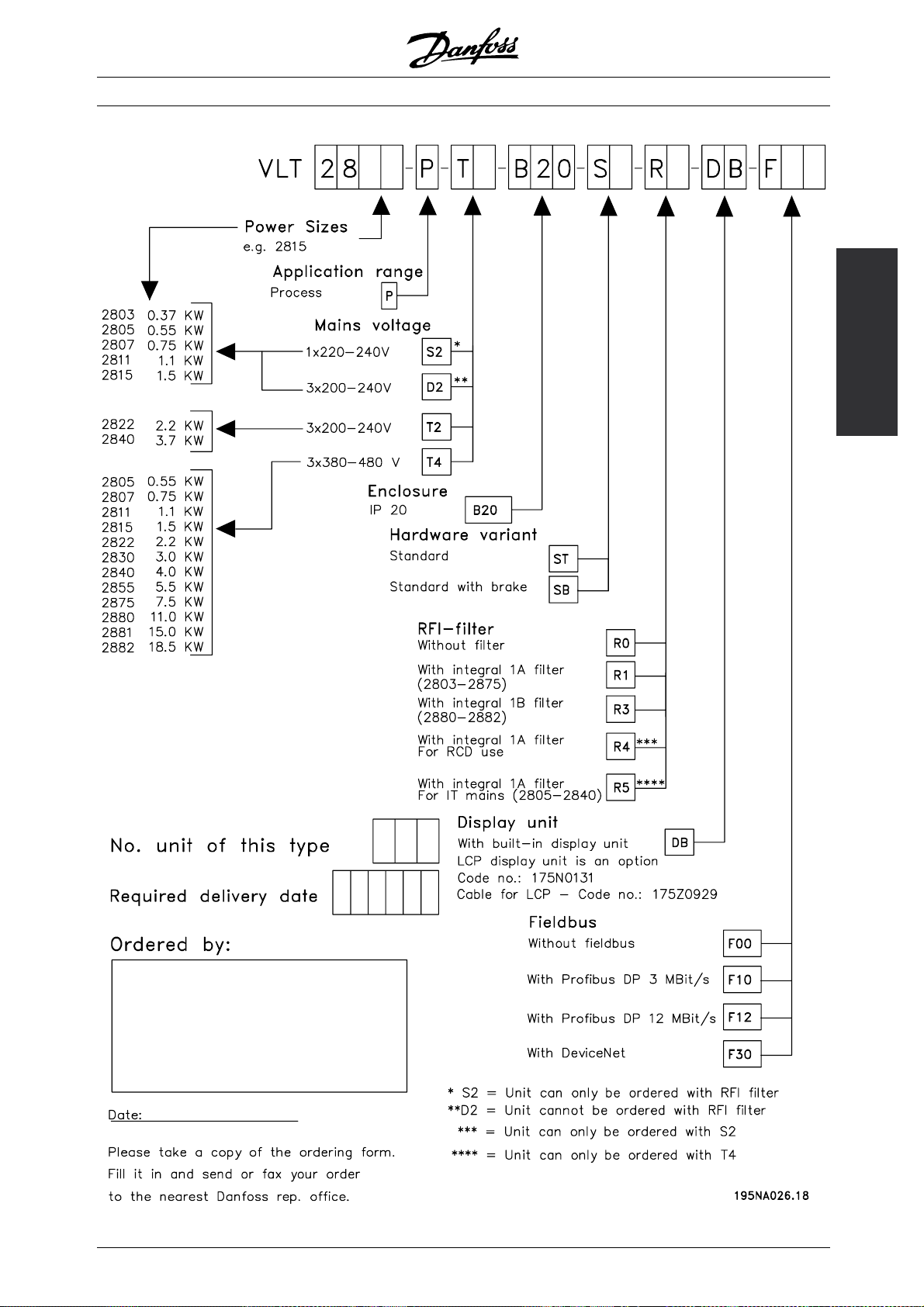
This section makes it easier for you to specify and
order a VLT 2800.
Choice of frequency converter
The frequency converter must be chosen on the
basis of the present motor current at maximum
loading of the unit. The frequency converter’s rated
output current I
must be equal to or greater than
INV.
the required motor current.
VLT®2800 Series
Mains voltage
VLT2800is
ranges: 200-240 V and 380-480 V.
Select whether the frequency converter is
connected to a mains voltage of:
1 x 220 - 240 Volt mains voltage
available for two mains voltage
Typical sh a ft output
P
INV.
Max. constant ou tput
- 1 x 220 - 240 V single-phase AC voltage
- 3 x 200 - 240
- 3 x 380 - 480 V three-phase AC voltage
V three-phase A C voltage
Max. constant output power
current I
INV.
at 230 V S
Type [kW] [HP] [A] [kVA]
2803 0.37 0.5 2.2 0.9
2805 0.55 0.75 3.2 1.3
2807 0.75 1.0 4.2 1.7
2811 1.1 1.5 6.0 2.4
2815 1.5 2.0 6.8 2.7
3 x 200 - 240 Volt mains voltage
Typical sh a ft output
P
INV.
Max. constant ou tput
current I
INV.
Max. constant output power
at 230 V S
Type [kW] [HP] [A] [kVA]
2803 0.37 0.5 2.2 0.9
2805 0.55 0.75 3.2 1.3
2807 0.75 1.0 4.2 1.7
2811 1.1 1.5 6.0 2.4
2815 1.5 2.0 6.8 2.7
2822 2.2 3.0 9.6 3.8
2840 3.7 5.0 16.0 6.4
2800
Introduction to VLT
INV.
INV.
MG.28.E9.02 - VLT is a registered Danfoss trademark
9
Page 10
3 x 380 - 480 Volt mains voltage
VLT®2800 Series
Typical sh a ft output
P
INV.
Max. constant ou tput
current I
INV.
Max. constant output power
at 400 V S
Type [kW] [HP] [A] [kVA]
2805 0.55 0.75 1.7 1.1
2807 0.75 1.0 2.1 1.7
2811 1.1 1.5 3.0 2.0
2815 1.5 2.0 3.7 2.6
2822 2.2 3.0 5.2 3.6
2830 3.0 4.0 7.0 4.8
2840 4.0 5.0 9.1 6.3
2855 5.5 7.5 12.0 8.3
2875 7.5 10.0 16.0 11.1
2880 11 15 24 16.6
2881 15 20 32 22.2
2882 18.5 25 37.5 26.0
■Enclosure
All VLT 2800 units are supplied with IP 20
enclosure as standard.
This enclosure level is idea l for panel mounting
in areas where a h igh degree of protection is
required; at the same time IP 20 enclosures
allow side-by-side installation with
for extra cooling equipment.
IP 20 units can be upgraded with IP 21 / top
coverand/orNEMA1byfittingatermin
See ordering number for terminal cover under
Accessories for VLT 2800 .
out any need
al cover.
■RFI filter
VLT 2800 is available with or without an integral
1A RFI-filter. The integral 1A RFI filter complies
with EMC standards EN 55011-1A.
With an integral RFI filter there is compliance with EN
55011-1B with a max. 15-metre screened/armoured
motor cable on VLT 2803-2815 1 x 220-240 Volt.
VLT 2880-82 with integral 1B filter comply with
EMC standard EN 50011 - 1B
INV.
In a ddition, VLT 2880-82 units are supplied with
Nema 1 enclosure as standard.
■Brake
VLT 2800 is available with or without an integral
brake module. See also the section entitled Brake
resistors for ordering a
■Wobble function
The wobble function is used for winding applications
in the textile industries. All VLT 2800 frequency
converters are suppl
standard feature. The frequency converter is able to
operate a motor, which turns a grooved drum. During
winding, the gro
correct position on the bobbin, in a diamond pattern.
For further informat ion, see VLT 2800 Wobble
Instruction MI
oved drum places the thread in the
50JXYY.
Brake resistor.
ied with a wobble function as a
■Harmonic filter
The harmonic currents do not affect power
consumption directly, but they increase the heat losses
in the installation (transformer, cables). That is why, in
a system with a relatively high percentage of rectifier
load, it is important to keep the harmonic currents at
a low level so as to avoid a transformer overload and
high cable temperature. For the purpose of ensuring
low harmonic currents, VLT 2822-2840 3 x 200-240
V and VLT 2805-2882 380-480 V are fitted with coils
in their intermediate circuit as standard. This reduces
the input current I
Please note that 1 x 220-240 V units are not supplied
with coils in their intermediate circuit.
■FC protocol
Danfoss frequency converters are able to fulfill
many different functions in a monitoring system.
The frequency converter can be integrated directly
in an overall surveillance system, which will
allow detailed process data to be transferred
via serial communication.
by typically 40 %.
RMS
10
MG.28.E9.02 - VLT is a registered Danfoss trademark
Page 11

VLT®2800 Series
The protocol standard is based on an RS 485
bus system with a maximum transmission speed
of 9600 baud. The following Drive profiles
are supported as standard:
- FC Drive, which is a profile adapted to Danfoss.
- Profidrive, which supports the profidrive profile.
See Serial communicat ion for further details of
telegram structure and Drive profile.
■Fieldbus option
The increasing information requirements in industry
make it nece ssary to collect or visualize many different
process data. Important process data help the system
technician with the daily monitoring of the system. The
large amounts of data involved in m ajor systems make
a higher transmission speed than 9600 baud desirable.
Fieldbus option
Profibus
Profibus is a fieldbus system, which can be used
for linking automation devices such as sensors
and actuators with the controls by means of
a two-conductor cable. Profibus DP is a very
fast communication protocol, made specially for
communication between the automation system
and various types of equipment.
Profibus is a registered trade mark.
MODBUS is often applied in Gas and Oil appl ications,
but also in building, infrastructure, transportation and
energy, applicat ions are m aking use of its benefits.
2800
Introduction to VLT
DeviceNet
DeviceNet fieldbus systems can be used for linking
automation devices such as sensors and actuators with
the controls by means of a four-wire conductor cable.
DeviceNet is a medium speed communication protocol,
made specially for communication between the
automation system and various types of equipment.
Units with DeviceN et protocol cannot be controlled
by FC protocol and Profidrive protocol.
VLT Software Dialog can be used on the Sub D plug.
■Modbus RTU
MODBUS RTU (Remote Terminal Unit) Protocol is
a m essaging structure developed by Modicon in
1979, used to establish master-slave/client-server
communication between intelligent devices.
MODBUS is used to monitor and program
devices; to communicate intelligent devices
with sensors and instruments; to monitor field
devicesusingPCsandHMIs.
MG.28.E9.02 - VLT is a registered Danfoss trademark
11
Page 12
VLT®2800 Series
■Motor coils
By fitting the motor coil module between the frequency
converter and the motor it is possible to use up
to 200 metres of unscreened/unarmoured motor
cable or 100 metres of screened/armoured motor
cable. The motor c oil module has an enclosure of
IP 20 and can be installed side-by-side.
NB!:
To have long motor cables and still comply
with EN55011-1A, motor coil and EMC filter
for long motor cables are needed.
NB!:
To comply with EN55011-1A the EMC filter for
long motor cables can only be fitted to a VLT
2800 with integral 1A filter (R1 option).
See also the section EMC Emission.
Technical data for VLT 2803-2875 Motor coils
Max. cable length (un screened/unarmoured)
Max. cable length (screened/armoured)
1)
1)
200 m
100 m
Enclosure IP 20
Max. rated c urre nt
Max. voltage
1)
1)
16 A
480 V AC
Min. distance between VLT and motor coil Side-by-side
Min. distance above and below motor coil 100 mm
Dimensions H x W x D (mm)
2)
200 x 90 x 152
Weight 3.8 kg
1)
Parameter 411 Switching frequency =4500Hz.
2)
For mechanical dimensions see under
See ordering number for motor coil module
under Accessories for VLT 2800.
Mechanical dimensions.
12
MG.28.E9.02 - VLT is a registered Danfoss trademark
Page 13
■RFI 1B filter
All frequency converters will cause electromagnetic
noise in the mains supply w hen they are operating.
An RFI (Radio Frequency Interference) filter will reduce
theelectromagneticnoiseinthemainssupply.
Without an RFI filter there is a risk that a frequency
converter will disrupt other electrical components
VLT®2800 Series
that are connected to the mains and might
thus cause operating disruption.
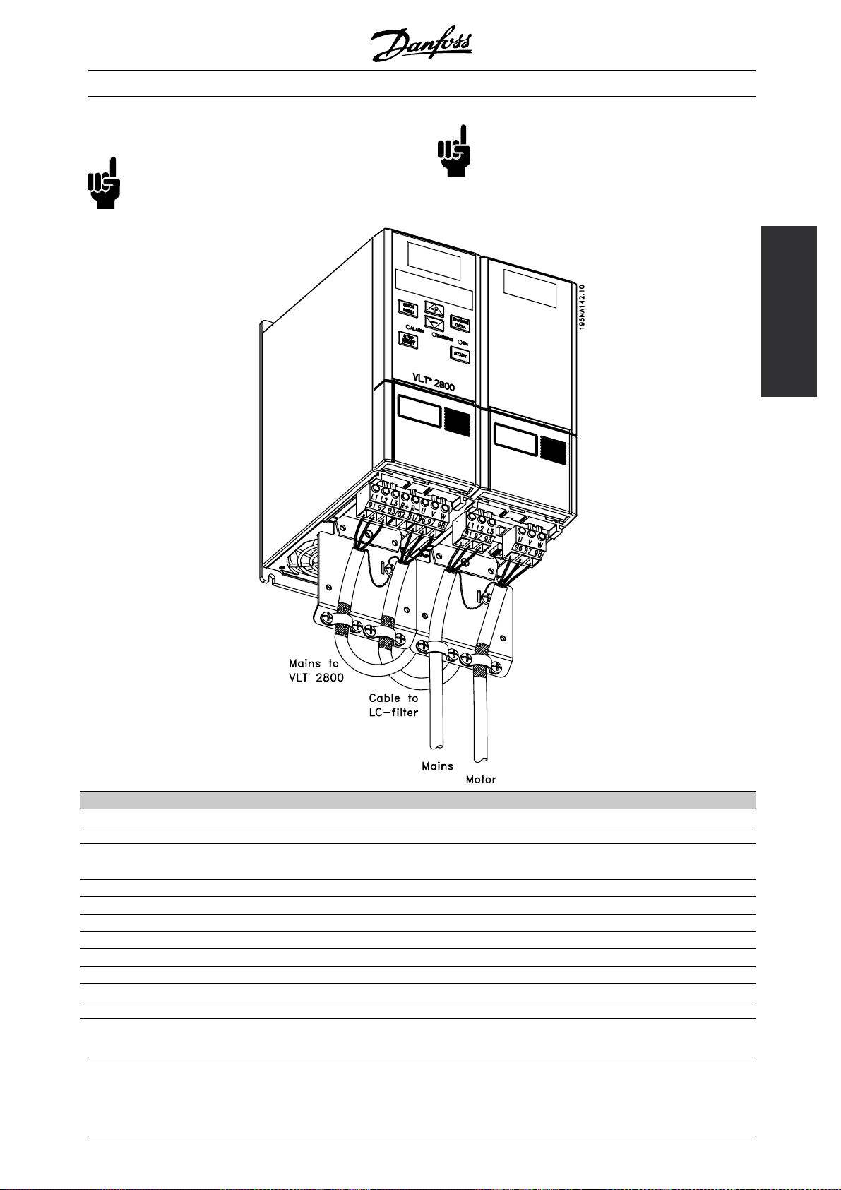
By fitting an RFI 1B filter m od ule between the mains
supply and the VLT 2800, the VLT 2800 complies
with the EMC norm EN 55011-1B.
NB!:
To comply with EN 55011-1B the RFI 1B
filter module must be fitted together with a
VLT 2800 with integral 1A RFI filter.
2800
Introduction to VLT
Technical data for VLT 2803-2875 RFI 1B filter
Max. cable length ( screened/armoured) 200-240 V 100 m (At 1A: 100 m)
Max. cable length ( screened/armoured) 380-480 V 25 m (At 1A: 50 m)
Enclosure IP 20
Max. rated current 16 A
Max. Voltage 480 V AC
Max. voltage to earth 300 V AC
Min. distance between VLT and RFI 1B filter Side-by-Side
Min. distance above and below RFI 1B filter 100 mm
Dimensions H x W x D (mm)
1)
200 x 60 x 87
Weight 0.9 kg
1)
For mechanical dimensions see under
Mechanical dimensions.
MG.28.E9.02 - VLT is a registered Danfoss trademark
See ordering number for RFI 1B filter module
under Accessories for VLT 2800.
13
Page 14
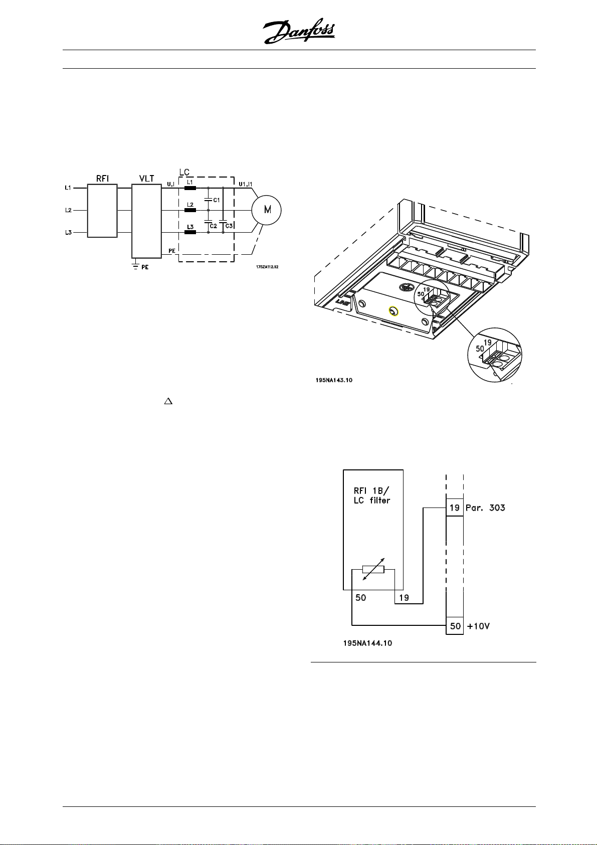
■RFI 1B/LC filter
The RFI 1B/LC filter contains both an RFI module
that complies with EN 55011-1B and an LC filter
that reduces the acoustic noise.
LC filter
When a motor is controlled by a frequency converter, at
times you will be able to hear the acoustic noise from
the motor. The noise, which is caused by the design of
the motor, is generated e very time one of the inverter
contacts in the frequency converter is activated. The
frequency of the acoustic noise therefore corresponds
to the frequency converter’s connection frequency.
VLT®2800 Series
Installation of thermistor (PTC)
The RFI 1B/LC filter has an i ntegral thermistor (PTC),
which is activated if an overtemperature arises. The
frequency converter can be programmed to stop the
motor and activatee an alarm via a relay output or
a digital output if the the rmistor is activated.
The filter reduces the voltage’s du/dt, the peak voltage
and ripple current Itothemotor,sothatthe
U
peak
current and voltage are almost sine-shaped. The
acoustic motor noise is thus reduced to a minimum.
Becauseoftheripplecurrentinthecoilssome
noisewillbeemittedbythecoils. Thisproblem
can be solved completely by fitting the filter
inside a cabinet or equivalent.
Danfoss can supply an LC filter for the frequency
converter, which muffles the acoustic motor noise.
Beforethefiltersareputintouseyoumustensurethat:
- rated current is observed
- mains voltage is 200-480 V
- parameter 412 Variable switching frequency
is set to LC filter attached [3]
- output frequency is max. 120 Hz
See drawing on the next page.
The thermistor must be connected between terminal 50
(+10V) and one of the digital inputs 18 , 19, 27 and 29.
In parameter 128 Motor thermal protection Thermistor
warning [1] or Thermistor trip [2] are selected.
The thermistor is connected as follows:
14
MG.28.E9.02 - VLT is a registered Danfoss trademark
Page 15
VLT®2800 Series
■RFI 1B/LC filter
NB!:
To comply with EN 55011-1B the RFI 1B
filter module must be fitted to a VLT 2800
with integral 1A RFI filter.
NB!:
The 1B/LC filter is not suitable for 200 V devices
due to the high 1Ø input current.
2800
Introduction to VLT
Technical d ata for VLT 280 3-2840 RFI 1B/LC filter
Max. cable length (screened/armoured) 380-480 V 25 m (At 1A: 50 m)
Enclosure IP 20
Max. rated current 4.0 (Order no.: 195N3100); 9.1 (Order no.:
195N3101)
Max. voltage 480 V AC
Max. voltage to earth 300 V AC
Min. distance between VLT and RFI 1B/LC filter Side-by-Side
Min. distance abo ve and below RFI 1B/LC filter 100 mm
Dimensions 195N3100 4.0 A H x W x D (mm) 200 x 75 x 168
Dimensions 195N3101 9.1 A H x W x D (mm) 267.5 x 90 x 168
Weight 195N3100 4.0 A 2.4 kg
Weight 195N3101 9.1 A 4.0 kg
MG.28.E9.02 - VLT is a registered Danfoss trademark
15
Page 16
VLT®2800 Series
■EMC filter for long motor cables
NB!:
Set switching frequency, parameter
411, to 4500 Hz
NB!:
Fitting position of frequency converter:
Vertical only.
NB!:
To have long motor cables and still comply
with EN55011-1A, motor coil and EMC filter
for long motor cables are needed.
NB!:
NB: To comply with EN55011-1A the EMC filter
for long motor cables can only be fitted to a
VLT 2800 with integral 1A filter (R1 opt ion).
See also the section EMC Emission.
Technical data for VLT 2805-2875 380-480 V EMC filter for long motor cables
Max. cable length (screened/armoured) VLT 2805-2875 380-480 V: 100 m
Enclosure IP 20
Max. rated current 192H4719: 3.2 A, 192H4720: 9.0 A, 192H4893: 16 A
Input voltage range 3 x 380-480 V ± 10%
Mains frequency 50-60 Hz
Input Terminals 2,5 mm2(192H4893 4 mm2)
Output Flexible cords with sleeves
Design Metal housing (suited for foot print and side mounting to VLT
2800)
Min. distance above and below filter 100 mm
Ambient temperature Ta= 50 °C
Dimensions 192H4719 H x W x D (mm)1244 x 75 x 45
Dimensions 192H4720 H x W x D (mm)1313 x 90 x 50
Dimensions 192H4893 H x W x D (mm)1313 x 140 x 50
See ordering numbers for EMC filter for long motor cables in Accessories for V L T 2800
1
For drawin g and more detailed dimensions, see in Mechanical dimensions
■Control unit
The frequency converter is always supplied
with an integral control unit.
All displays are in the form of a six-digit LED
display capable of showing one item of operating
data continuously during normal operation. As a
supplement to the display, there are three indicator
lamps for voltage (ON), warning (WARNING) and
alarm (ALARM). Most of the frequency converter’s
parameter Setups can be changed immediately
via the integral control panel.
An LCP 2 control panel to be connected via a
plug to the front of the frequency converter is
available as an option. The LCP 2 control panel
can be installed up to 3 metres away from the
frequency converter, e.g. on a front panel, by means
of the accompanying mount ing kit.
All displays of data are via a 4-line alpha-numerical
display, which in normal operation is able to show
4 operating data items and 3 operation modes
continuously. During programming, all the i nformat ion
required for quick, efficient parameter Setup of the
frequency converter is displayed. As a supplement
to the display, there are three indicator lamps
for voltage (ON), warning (WARNING) and alarm
(ALARM). Most of the frequency converter’s parameter
Setups can be changed immediately via the LCP
2 control panel. See also the section entitled The
LCP 2 control unit in the Design Guide.
16
MG.28.E9.02 - VLT is a registered Danfoss trademark
Page 17
VLT®2800 Series
■Ordering numbers for VLT 2800 200-240 V
0,37 kW VLT 2803 1 x 220-240 V / 3 x 200-240 V
RFI Unit Profibus
1)
DP
3MBits/s
- ST - - 195N0001
- SB - - 195N0002
R1 ST - - 195N0003
R1 SB - - 195N0004
-ST - 195N0005
-SB - 195N0006
R1 ST - 195N0007
R1 SB - 195N0008
-ST - 195N0009
-SB - 195N0010
R1 ST - 195N0011
R1 SB - 195N0012
0,55 kW VLT 2805 1 x 220-240 V / 3 x 200-240 V
RFI Unit Profibus
1)
DP
3MBits/s
- ST - - 195N0013
- SB - - 195N0014
R1 ST - - 195N0015
R1 SB - - 195N0016
-ST - 195N0017
-SB - 195N0018
R1 ST - 195N0019
R1 SB - 195N0020
-ST - 195N0021
-SB - 195N0022
R1 ST - 195N0023
R1 SB - 195N0024
0,75 kW VLT 2807 1 x 220-240 V / 3 x 200-240 V
RFI Unit Profibus
1)
DP
3MBits/s
- ST - - 195N0025
- SB - - 195N0026
R1 ST - - 195N0027
R1 SB - - 195N0028
-ST - 195N0029
-SB - 195N0030
R1 ST - 195N0031
R1 SB - 195N0032
-ST - 195N0033
-SB - 195N0034
R1 ST - 195N0035
R1 SB - 195N0036
DeviceNet Ordering no.
DeviceNet Ordering no.
DeviceNet Ordering no.
1,1 kW VLT 2811 1 x 220-240 V / 3 x 200-240 V
RFI Unit Profibus
1)
DP
DeviceNet Ordering no.
3MBits/s
- ST - - 195N0037
- SB - - 195N0038
R1 ST - - 195N0039
R1 SB - - 195N0040
-ST - 195N0041
-SB - 195N0042
R1 ST - 195N0043
R1 SB - 195N0044
-ST - 195N0045
-SB - 195N0046
R1 ST - 195N0047
R1 SB - 195N0048
1,5 kW VLT 2815 1 x 220-240 V / 3 x 200-240 V
RFI Unit Profibus
1)
DP
DeviceNet Ordering no.
3MBits/s
- ST - - 195N0049
- SB - - 195N0050
R1 ST - - 195N0051
R1 SB - - 195N0052
-ST - 195N0053
-SB - 195N0054
R1 ST - 195N0055
R1 SB - 195N0056
-ST - 195N0057
-SB - 195N0058
R1 ST - 195N0059
R1 SB - 195N0060
2,2 kW V LT 2822 3 x 200-240 V
RFI Unit Profibus
1)
DP
DeviceNet Ordering no.
3MBits/s
- ST - - 195N0061
- SB - - 195N0062
R1 ST - - 195N0063
R1 SB - - 195N0064
-ST - 195N0065
-SB - 195N0066
R1 ST - 195N0067
R1 SB - 195N0068
-ST - 195N0069
-SB - 195N0070
R1 ST - 195N0071
R1 SB - 195N0072
2800
Introduction to VLT
MG.28.E9.02 - VLT is a registered Danfoss trademark
17
Page 18
3,7 kW VLT 2840 3 x 200-240 V
RFI Unit Profibus
1)
DP
3MBits/s
- ST - - 195N0073
- SB - - 195N0074
R1 ST - - 195N0075
R1 SB - - 195N0076
-ST - 195N0077
-SB - 195N0078
R1 ST - 195N0079
R1 SB - 195N0080
-ST - 195N0081
-SB - 195N0082
R1 ST - 195N0083
R1 SB - 195N0084
DeviceNet Ordering no.
ST: Standard unit.
SB: Standard unit with integral brake.
R1: With RFI filter that complies w
ith EN 55011-1A.
VLT®2800 Series
NB!:
For VLT 2803-2815 with an R1 filter it is
only possible to c o nnect single-phase mains
voltage 1 x 220 - 240 Volt.
1) Also available in 12 MBi
t/s version.
18
MG.28.E9.02 - VLT is a registered Danfoss trademark
Page 19

VLT®2800 Series
■Ordering numbers for VLT 2800 380-480V
0,55kW VLT28053x380-480V
RFI Unit Profibus
1)
DP
3MBit/s
- ST - - 195N1001
- SB - - 195N1002
R1 ST - - 195N1003
R1 SB - - 195N1004
-ST - 195N1005
-SB - 195N1006
R1 ST - 195N1007
R1 SB - 195N1008
-ST - 195N1009
-SB - 195N1010
R1 ST - 195N1011
R1 SB - 195N1012
0,75 kW VLT 2807 3 x 380-480 V
RFI Unit Profibus
1)
DP
3MBit/s
- ST - - 195N1013
- SB - - 195N1014
R1 ST - - 195N1015
R1 SB - - 195N1016
-ST - 195N1017
-SB - 195N1018
R1 ST - 195N1019
R1 SB - 195N1020
-ST - 195N1021
-SB - 195N1022
R1 ST - 195N1023
R1 SB - 195N1024
1,1 kW VLT 2811 3 x 380-480 V
RFI Unit Profibus
1)
DP
3MBit/s
- ST - - 195N1025
- SB - - 195N1026
R1 ST - - 195N1027
R1 SB - - 195N1028
-ST - 195N1029
-SB - 195N1030
R1 ST - 195N1031
R1 SB - 195N1032
-ST - 195N1033
-SB - 195N1034
R1 ST - 195N1035
R1 SB - 195N1036
DeviceNet Ordering no.
DeviceNet Ordering no.
DeviceNet Ordering no.
1,5 kW V LT 2815 3 x 380-480 V
RFI Unit Profibus
1)
DP
DeviceNet Ordering no.
3MBit/s
- ST - - 195N1037
- SB - - 195N1038
R1 ST - - 195N1039
R1 SB - - 195N1040
-ST - 195N1041
-SB - 195N1042
R1 ST - 195N1043
R1 SB - 195N1044
-ST - 195N1045
-SB - 195N1046
R1 ST - 195N1047
R1 SB - 195N1048
2,2 kW V LT 2822 3 x 380-480 V
RFI Unit Profibus
1)
DP
DeviceNet Ordering no.
3MBit/s
- ST - - 195N1049
- SB - - 195N1050
R1 ST - - 195N1051
R1 SB - - 195N1052
-ST - 195N1053
-SB - 195N1054
R1 ST - 195N1055
R1 SB - 195N1056
-ST - 195N1057
-SB - 195N1058
R1 ST - 195N1059
R1 SB - 195N1060
3,0 kW V LT 2830 3 x 380-480 V
RFI Unit Profibus
1)
DP
DeviceNet Ordering no.
3MBit/s
- ST - - 195N1061
- SB - - 195N1062
R1 ST - - 195N1063
R1 SB - - 195N1064
-ST - 195N1065
-SB - 195N1066
R1 ST - 195N1067
R1 SB - 195N1068
-ST - 195N1069
-SB - 195N1070
R1 ST - 195N1071
R1 SB - 195N1072
2800
Introduction to VLT
MG.28.E9.02 - VLT is a registered Danfoss trademark
19
Page 20

VLT®2800 Series
4,0 kW VLT 2840 3 x 380-480 V
RFI Unit Profibus
1)
DP
DeviceNet Ordering no.
3MBit/s
- ST - - 195N1073
- SB - - 195N1074
R1 ST - - 195N1075
R1 SB - - 195N1076
-ST - 195N1077
-SB - 195N1078
R1 ST - 195N1079
R1 SB - 195N1080
-ST - 195N1081
-SB - 195N1082
R1 ST - 195N1083
R1 SB - 195N1084
5,5 kW VLT 2855 3 x 380-480 V
RFI Unit Profibus
1)
DP
DeviceNet Ordering no.
3MBit/s
- ST - - 195N1085
- SB - - 195N1086
R1 ST - - 195N1087
R1 SB - - 195N1088
-ST - 195N1089
-SB - 195N1090
R1 ST - 195N1091
R1 SB - 195N1092
-ST - 195N1093
-SB - 195N1094
R1 ST - 195N1095
R1 SB - 195N1096
11 kW VLT 2880 3 x 380-480 V
RFI Unit Profibus
1)
DP
DeviceNet Ordering no.
3MBit/s
- ST - - 195N1109
- SB - - 195N1110
R3 ST - - 195N1111
R3 SB - - 195N1112
-ST - 195N1113
-SB - 195N1114
R3 ST - 195N1115
R3 SB - 195N1116
-ST - 195N1117
-SB - 195N1118
R3 ST - 195N1119
R3 SB - 195N1120
15 kW VLT 2881 3 x 380-480 V
RFI Unit Profibus
1)
DP
DeviceNet Ordering no.
3MBit/s
- ST - - 195N1121
- SB - - 195N1122
R3 ST - - 195N1123
R3 SB - - 195N1124
-ST - 195N1125
-SB - 195N1126
R3 ST - 195N1127
R3 SB - 195N1128
-ST - 195N1129
-SB - 195N1130
R3 ST - 195N1131
R3 SB - 195N1132
7,5 kW VLT 2875 3 x 380-480 V
RFI Unit Profibus
1)
DP
DeviceNet Ordering no.
3MBit/s
- ST - - 195N1097
- SB - - 195N1098
R1 ST - - 195N1099
R1 SB - - 195N1100
-ST - 195N1101
-SB - 195N1102
R1 ST - 195N1103
R1 SB - 195N1104
-ST - 195N1105
-SB - 195N1106
R1 ST - 195N1107
R1 SB - 195N1108
ST: Standard unit.
SB: Standard unit with integral brake.
R1: With RFI filter that complies with EN 55011-1A.
R3: With RFI filter that complies with EN 55011-1
B.
18.5 k W VLT 2882 3 x 380-480 V
RFI Unit Profibus
1)
DP
DeviceNet Ordering no.
3MBit/s
- ST - - 195N1133
- SB - - 195N1134
R3 ST - - 195N1135
R3 SB - - 195N1136
-ST - 195N1137
-SB - 195N1138
R3 ST - 195N1139
R3 SB - 195N1140
-ST - 195N1141
-SB - 195N1142
R3 ST - 195N1143
R3 SB - 195N1144
1) Also available in 12 MBit/s.
20
MG.28.E9.02 - VLT is a registered Danfoss trademark
Page 21
VLT®2800 Series
2800
Introduction to VLT
MG.28.E9.02 - VLT is a registered Danfoss trademark
21
Page 22

VLT®2800 Series
■PC Software tools
PC Software - MCT 10
All drives are equipped with a serial communication
port. We provide a PC tool for communication
between PC and frequency converter, VLT Motio n
Control Tool MCT 10 Set-up Software.
MCT 10 Set-up Software
MCT 10 has been designed as an easy to
use interactive tool for setting parame ters in
our frequency converters.
The MCT 10 Set-up Software will be useful for:
• Planning a communic ation network off-line. MCT 10
contains a complete frequency converter database
• Commissioning frequency converters on line
• Saving settings for all frequency converters
• Replacing a drive in a network
• Expandinganexistingnetwork
• Future developed drives will be supported
MCT10Set-upSoftwaresupportProfibusDP-V1via
a Master class 2 connection. It makes it possible to
on line read/write parameters in a frequency converter
via the Profibus network. This will eliminate the
need for an extra communication network.
The MCT 10 Set-up Software Modules
The following modules are included in the
software package:
MCT 10 Set-up Software
Setting parameters
Copy to and from frequency
converters
Documentation and print out of
parameter settings incl. diagrams
SyncPos
Creating SyncPos programme
Ordering number:
Please order your CD containing MC
Software using code number 130B1000.
T10Set-up
MCT 31
The MCT 31 harmonic calculation PC tool enables
easy estimation of the harmonic distortion in a given
application. Both the harmonic distortion of Danfoss
frequency converters as well as non-Danfoss frequency
converters with different additional harmonic reduction
measurements, such as Danfoss AHF filters and
12-18-pulse rectifiers, can be calculated.
Ordering number:
Please order your CD containing the MCT 31 PC
tool using code number 130B1031.
22
MG.28.E9.02 - VLT is a registered Danfoss trademark
Page 23
VLT®2800 Series
■Accessories for the VLT 2800
Type Description Ordering no.
Motor coil The motor coil module can be used for VLT 2803-2875 195N3110
RFI 1B filter The RFI 1B filter module can be used for VLT 2803-2875 195N3103
RFI 1B/LC filter 4 A The RFI 1B/LC filter 4 A can be used for VLT 2803-2805
200-240 V and VLT 2805-2815 380-400 V
RFI 1B/LC filter 9.1 A RFI 1B/LC filter 9.1 A can be used for VLT 2807-2815
200-240 V and VLT 2822-2840 380-400 V
EMC filter EMC filter for long motor cables can be used for VLT
2805-2815 380-480 V
EMC filter EMC filter for long motor cables can be used for VLT
2822-2840 380-480 V
EMC filter EMC filter for long motor cables can be used for VLT
2855-2875 380-480 V
NEMA 1 terminal cover VLT 2803-2815 200-240 V, VLT 2805-2815 380-480 V 195N1900
NEMA 1 terminal cover VLT 2822 200-240 V, VLT 2822-2840 380-480 V 195N1901
NEMA 1 terminal cover VLT 2840 200-240 V, VLT 2855-2875 380-480 V 195N1902
IP 21 top cover VLT 2803-2815 200-240 V, VLT 2805-2815 380-480 V 195N2179
IP 21 top cover VLT 2822 200-240 V, VLT 2822-2840 380-480 V 195N2180
IP 21 top cover VLT 2840 200-240 V, VLT 2855-2875 380-480 V 195N2181
IP 21 top cover VLT 2880-2882 380-480 V 195N2182
LCP 2 control unit LCP 2 for programming the frequency converter 175N0131
Cable for LCP 2 control unit Cable from LCP 2 to frequency converter 175Z0929
DeviceNet cable Cable for DeviceNet connection 195N3113
LCP2remote-mountingkit Kitforremote-mountingofLCP2(incl. 3mcable,
excl. LCP 2)
LOP (Loca l Operation Pad) LOP can be used fo r setting the reference
andstart/stopviathecontrolterminals.
VLT Software Dialog CD-ROM version
1
MCT 10 Set-up Software 130B1000
External heat sink, small
External heat sink, large
1)
Incl. the modules Basis, Logging, Template,
2
2
W x H x D = 222 x 450 x 65mm
W x H x D = 288 x 450 x 71mm
3
3
Guided Tour in 6 languages (Danish, English,
German, Italian, Spanish and French).
2)
For further information see VLT 2800 Cold
Plate Instruction MI.28.DX.02.
195N3100
195N3101
192H4719
192H4720
192H4893
175Z0850
175N0128
175Z0967
195N3111
195N3112
2800
Introduction to VLT
MG.28.E9.02 - VLT is a registered Danfoss trademark
23
Page 24
■Dynamic braking
With the VLT 2800 the dynamic braking quality in an
application can be improved in two ways, either with
the aid of brake resistors or AC braking.
Danfoss offers a complete range of brake resistors
for all VLT 2800 frequency converters.
It is the job of the brake resistor to apply a
load to the intermediate circuit during braking,
thereby ensuring that the brake power can be
absorbed by the brake resistor.
Without a brake resistor, the intermediate circuit
voltage of the frequency converter would go on rising,
until cutting out for protection. The advantage of
using a brake resistor is that you can brake quickly
with large loads, e.g. on a conveyor belt.
Danfoss has chosen a solution in which the brake
resistor is not integrated into the frequency converter.
This gives the user the following advantages:
-Theresistor’s cycle time can be selected as required.
- The heat generated during braking can be
diverted outside the panel cabinet, where the
energy can possibly be utilised.
- No overhea ting of the e lectronic components,
even if the brake resistor is overloaded.
VLT®2800 Series
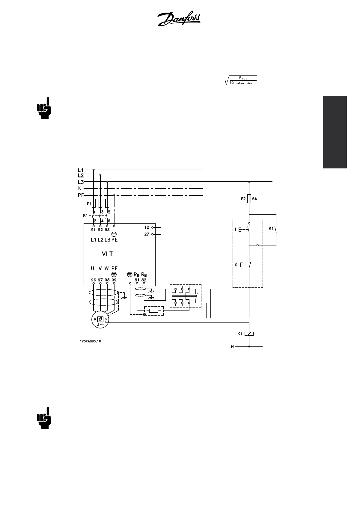
■Calculation of brake resistance
The following example and formula only apply
to VLT 2800 Series.
To ensure that the frequency converter does not cut
out for safety reasons when the motor brakes, the
resistance value is selected on the basis of the peak
braking effec t and the intermediate circuit voltage:
AC braking is an integrated function that is used
for applications in which there is a need for limited
dynamic braking. The AC braking function makes
it possible to reduce the brake power in the motor
instead of in a brake resistor. The function is intended
for applicati ons where the required braking torque
is less than 50% of rated torque. AC braking is
selected in par. 400 Brake function.
NB!:
The AC brake cannot be used if the
required braking torque is more than 50%
of rated braking torque. In such instances
a brake resistor must be used.
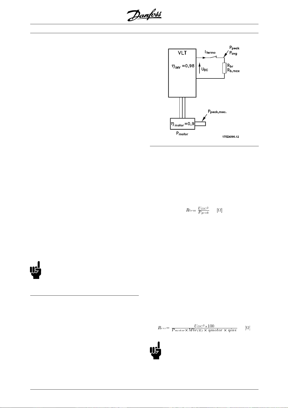
■Brake Setup
ThefigureshowsabrakeSetupwitha
frequency converter.
In the following paragraphs, expressions and
acronyms are used about brake Setups that
can be seen from the figure.
It can be seen that the brake resistance depends
on the intermediate circuit voltage (UDC).
With frequency converters that have a mains voltage
of 3 x 380 - 480 Volt, the brake will be active at
770 Volt (UDC); if the frequency converter has a
mains voltage of 3 x 200 - 240 Volt, the brake
will be active at 385 Volt (UDC).
You can also choose to use the brake resistance
recommended by Danfoss (R
guarantee that the frequency converter
brakeatthehighestbrakingtorque(M
). This is a
REC
is able to
). The
BR
recommended brake resistance can be seen from
the ordering table for brake resi
calculated as:
R
REC
stors.
NB!:
Remember to check that the brake resistance
can manage a voltage of 850 Volt or 430 Volt,
if Danfoss brake resistors are not being used.
24
MG.28.E9.02 - VLT is a registered Danfoss trademark
Page 25
VLT®2800 Series
η
is typically 0.90 and η
motor
is typically 0.98. For 400
INV
Volt and 200 Volt frequency converters, respectively,
at 160% braking torque can be written as:
R
REC
NB!:
The brake resistance selected should have
an ohmic value no more than 10% lower
than that recommended by Danfoss. I
lower brake resistance is selected there is a risk of
overcurrent, which can destroy the unit.
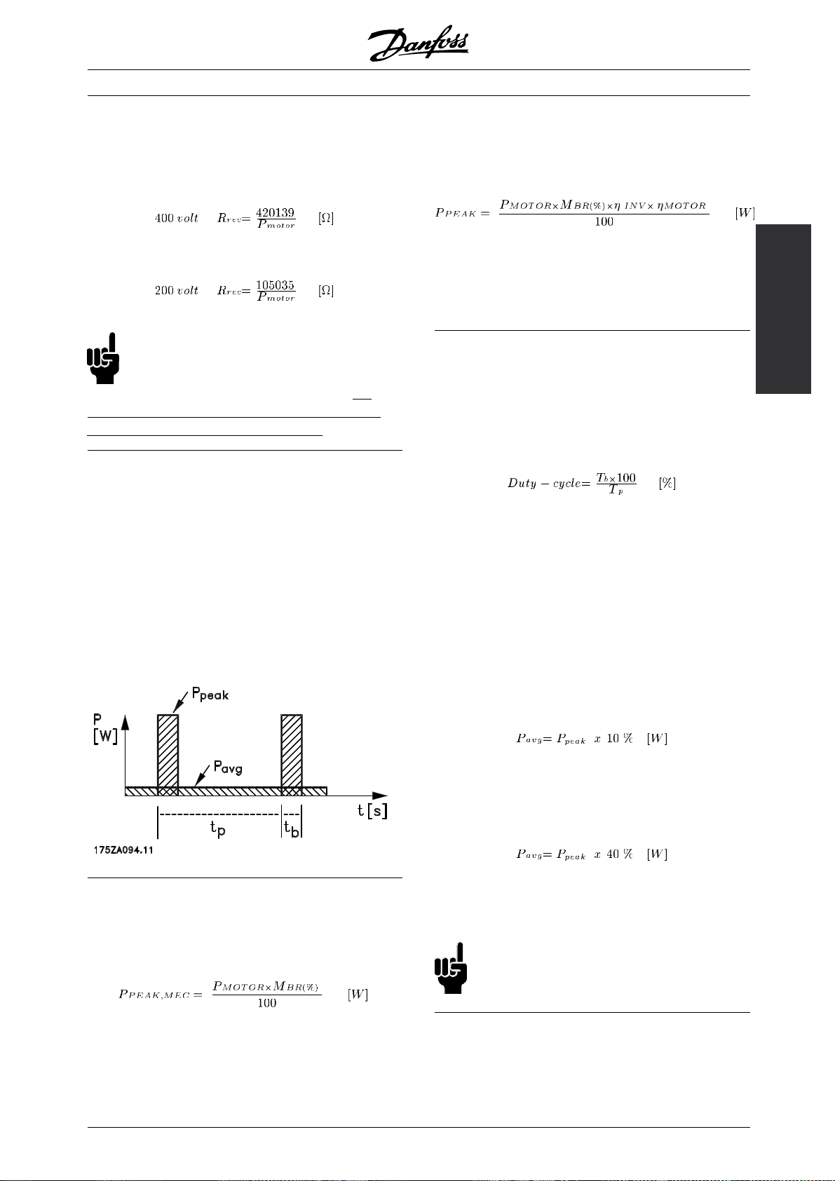
■Calculation of braking power
When calculating the braking pow er, it must be
ensured that the mean and pe ak powers can be
dissipated to the brake resistor. The mean power
is determined by the period time of the process,
i.e. for how long the brake is applied in relation to
the period time of the process. The peak power
is determined by the braking torque, which means
that during braking the brake resistor must be able
to dissipate the energy input. The figure shows the
relation between mean power and peak power.
f a
of the motor and the frequency converter. The
peak effect is calculated as follows:
If you select Danfoss’ recommended braking resistor
), you are certain that the braking resistance can
(R
REC
generate a braking torque of 160% on the m otor shaft.
■Calculation of mean power on brake resistor
The mean power is determined by the period of
the process, i.e. how long you brake in relation
to the period of the process.
Duty-cycle for braking is calculated as follows:
Tp= The process time in seconds.
= The braking time in seconds.
T
b
Danfoss sells brake resistors with variable duty-cycles
up to 40%. For example, with a 10% duty-cycle,
brake resistors can take up P
in 10% of the
peak
process period. The remaining 90% of the period
time is spent on redirecting surplus heat.
The mean power at 10% duty cycle can be
calculated as follows:
2800
Introduction to VLT
■Calculation of peak power of brake resistor
P
PEAK, MEC
is the peak power at which the motor
brakes on the motor shaft. It is calculated as follows:
P
is the term describing the braking power that
peak
is applied to the brake resistor when the motor
applies the brakes. P
, as the power is reduced by the efficiency
MEC
MG.28.E9.02 - VLT is a registered Danfoss trademark
is smaller than P
PEAK
PEAK,
The mean power at 40% duty cycle can be
calculated as follows:
These calculations apply to intermittent braking with
period times of up to 120 seconds.
NB!:
Period times longer than 120 sec. may lead
to overheating of the resistor.
■Continuous braking
For continuous braking, a brake resistor should be
selected in which the constant braking power does
not exceed the mean power P
of the brake resistor.
AVG
25
Page 26
VLT®2800 Series
Please contact your D anfoss supplier for
further information.
■D.C. injection braking
If the three-phase winding of the stator is fed with
direct current, a stationary magnetic field will be
set up in the stator bore causing a voltage to be
induced in the bars of the cage rotor as long as
the rotor is in motion. Since the electrical resistance
of the rotor cage is very low, even small induced
voltages can create a high rotor current. This current
will produce a strong braking effect on the bars
and hence on the rotor. As the speed falls, the
frequency of the induced voltage falls and with it the
inductive impedance. The ohmic resistance of the
rotor gradually becomes dominant and so increases
the braking effect as the speed comes down. The
braking torque generated falls away steeply just before
standstill and finally ceases when there is no further
movement. Direct current injection braking is therefore
not suitable for actually holding a load at rest.
■AC-braking
When the motor acts as a brake the DC-link voltage
will increase because energy is fed back to the
DC-link. The principle in AC-brake is to increase the
magnetisation during the braking and thereby increase
the thermal losses of the motor. Using par. 144 in VLT
2800 it is possible to adjust the size of the generator
torque that can be applied to the motor without the
intermediate circuit voltage exceeding the warning level.
The braking torque depends on the speed. With
the AC-brake function enabled and parameter 144
= 1,3 (factory setting) it is possible to brake with
about 50 % of rated torque below 2/3 of rated speed
and with about 25 % at rated speed. The function
is not working at low speed (below 1/3 of nominal
motor speed). It is only possible to run for about 30
seconds with pa rameter 144 greater than 1.2.
NB!:
If the value in parameter 144 is increased,
the motor current will simultaneously increase
significantly when generator loads are applied.
The parameter should therefore only be changed if
it is guaranteed during measurement that the motor
current in all operating situations will never exceed the
maximum permitted current in the motor. Please note:
The current can not be read out from the display.
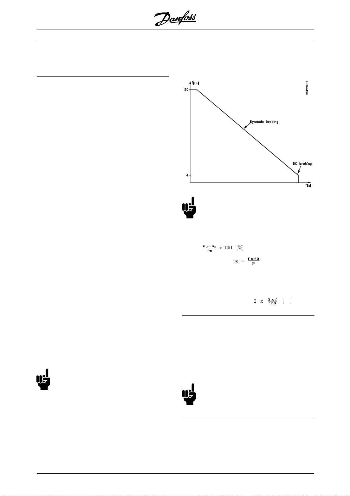
DC braking is to be applied a s required. The most
efficient way of doing this is by using a combinat ion of
dynamic and DC braking. See the illustration.
NB!:
When changing from dynamic to DC braking,
there will be a short period (2-6 milliseconds)
with very low braking torque.
How to calculate optimum DC-brake cut in frequency:
Slip S=
Synchronous speed [1/min]
f = frequency
p=no. ofpolepairs
= speed of the rotor
n
n
DC-brake cut in frequency =
Hz
■Brake cable
Max. length [m]: 20 m
The connection cable to the brake resistor must
be screened/armoured. Connect the screen
totheconductivebackplateatthefrequency
converter and to the brake resistor metal cabinet
by means of cable clamps.
NB!:
If D anfoss brake resistors are not used, it
must be ensured that the brake resistor
is induction-free.
■Optimal braking using resistor
Dynamic braking is useful from maximum speed
down to a certain frequency. Below this frequency
26
MG.28.E9.02 - VLT is a registered Danfoss trademark
Page 27
VLT®2800 Series
■Protective functions during installation
When a brake resistor is installed, the best
possible endeavors should be made to avoid
overloads, as the heat generating from a brake
resistor may involve a fire risk.
NB!:
The brake resistor should be fitted to a
nonflammable material.
For p rotection of the installation, a thermal relay
should be fitted that cuts off the frequency converter
if the brake current becomes too high. Flat
pack resistors are self-protecting.
Calculate the brake current setting of the
thermal relay as follows:
Itherm relay =
Rbris the current brake resistor value calculated in
the section on "Calc ulation of brake resistance". The
figure shows an installation with a thermal relay.
The brake current setting of thermal relay for Danfoss
40% brakeresistors can be found in the table further on.
2800
Introduction to VLT
Some of the Danfoss Brakeresistors contain a thermal
switch (see table further on). This switch is NC
(normally closed) and can be used e.g. coasting stop
reverse between terminal 12 and 27. The drive will
then coast, if the thermal switch is opened.
NB!:
The thermal switch is not a protective
device. For protection, use a thermal
switch as shown in the figure.
MG.28.E9.02 - VLT is a registered Danfoss trademark
27
Page 28
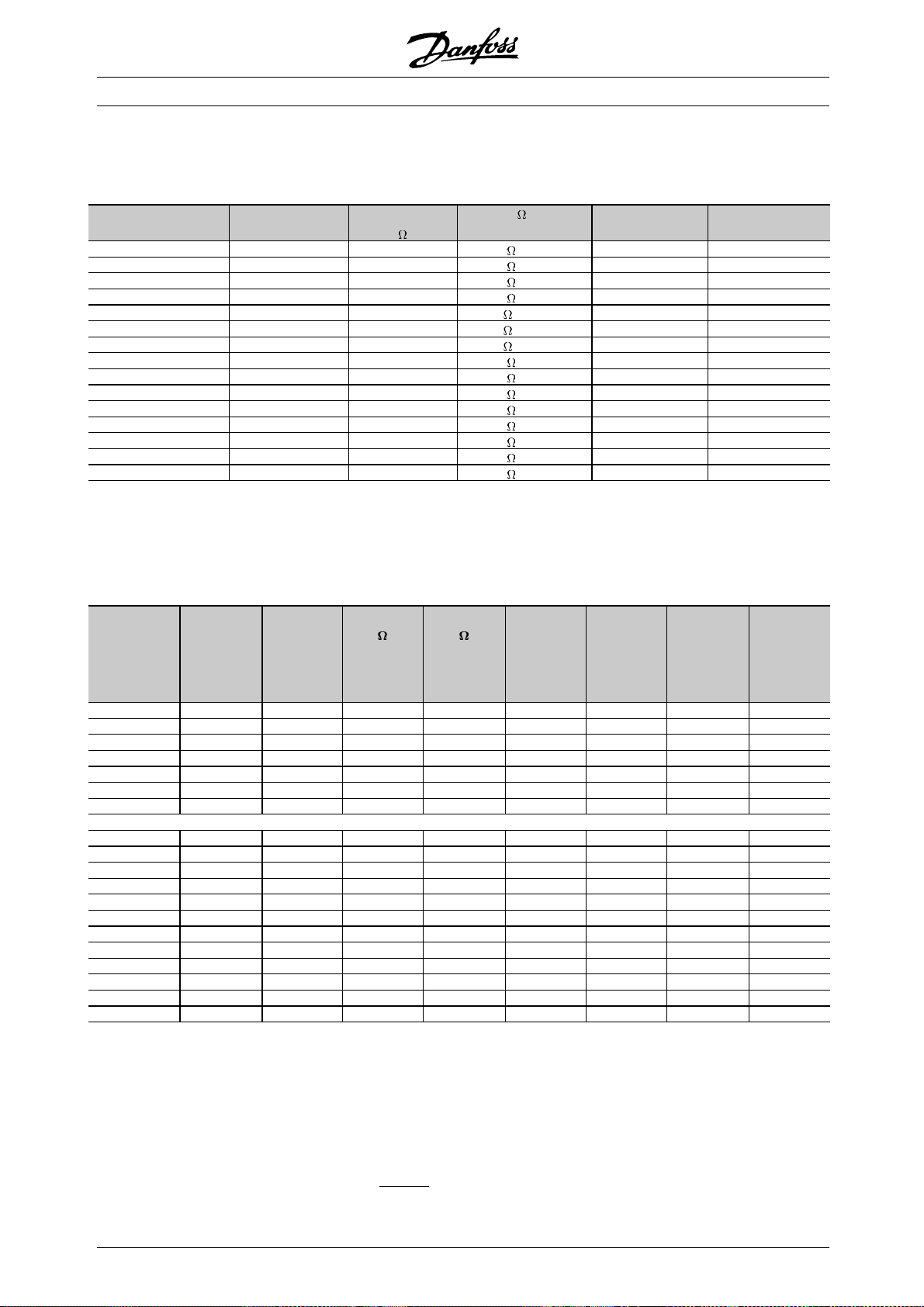
■Brake resistors
Flatpack brake resistors IP 65
VLT®2800 Series
Type P
motor
[kW]
R
MIN
[ ]
Size [ ]/[W]
per item
Duty cycle % Order no.
175Uxxxx
2803 (200 V) 0.37 297 330 /100W 30 1003
2805 (200 V) 0.55 198 220 /100W 20 1004
2807 (200 V) 0.75 135 150 /100W 14 1005
2811 (200 V) 1.10 99 100 /100W 8 1006
2815 (200 V) 1.50 69 72 / 200 W 16 0992
2822 (200 V) 2.20 43 50 / 200 W 9 0993
2840 (200 V) 3.70 21 50 / 200 W 11 2x0993
2805 (400 V) 0.55 747 830 /100W 20 1000
2807 (400 V) 0.75 558 620 /100W 14 1001
2811 (400 V) 1.10 387 430 /100W 8 1002
2815 (400 V) 1.50 297 310 /200W 16 0984
2822 (400 V) 2.20 198 210 /200W 9 0987
2830 (400 V) 3.00 135 150 /200W 5.5 0989
2830 (400 V) 3.00 135 300 /200W 11 2x0985
2840 (400 V) 4.00 99 240 /200W 11 2x0986
1
These two resistors must be connected in parallel. Order two
pieces.
See dimensions of Flatpack brake resistors on the next page.
Brake resistor for VLT 2803-2882 duty-cycle 40% data and codenumber
VLT type Intermit-
tent brak-
ing period
time
[seconds]
2803 (200 V) 120 0,37 297 330 0,16 0,7 1900* 1,5**
2805 (200 V) 120 0,55 198 220 0,25 1,1 1901* 1,5**
2807 (200 V) 120 0,75 135 150 0,32 1,5 1902* 1,5**
2811 (200 V) 120 1,1 99 110 0,45 2,0 1975* 1,5**
2815 (200 V) 120 1,5 74 82 0,85 3,2 1903* 1,5**
2822 (200 V) 120 2,2 50 56 1,00 4,2 1904* 1,5**
2840 (200 V) 120 3,7 22 25 3,00 11,0 1925 1,5**
P
motor
[kW]
R
[ ]
min
R
[ ]
rec
P
b, max
[kW]
Therm.re-
lay
[Amp]
Code
number
175Uxxxx
1
1
1
Cable
cross
section
[mm
2
]
2805 (400 V) 120 0,55 747 830 0,45 0,7 1976* 1,5**
2807 (400 V) 120 0,75 558 620 0,32 0,7 1910* 1,5**
2811 (400 V) 120 1,1 387 430 0,85 1,4 1911* 1,5**
2815 (400 V) 120 1,5 297 330 0,85 1,6 1912* 1,5**
2822 (400 V) 120 2,2 198 220 1,00 2,1 1913* 1,5**
2830 (400 V) 120 3,0 135 150 1,35 3,0 1914* 1,5**
2840 (400 V) 120 4,0 99 110 1,60 3,8 1979* 1,5**
2855 (400 V) 120 5,5 80 80 2,00 5,0 1977* 1,5**
2875 (400 V) 120 7,5 56 56 3,00 6,8 1978* 1,5**
2880 (400 V) 120 11 40 40 5,00 11,2 1997* 1,5**
2881 (400 V) 120 15 30 30 10,0 18,3 1998 2,5**
2882 (400 V) 120 18,5 25 25 13,0 22,8 1999 4**
*With KLIXON switch
**Always observe national and local regulations
P
motor
R
min
R
rec
P
b, max
Therm. relay : Brake current setting of thermal relay
:RatedmotorsizeforVLTtype
: Minimum permissible brake resistor
: Recommended brake resistor (Danfoss)
: Brake resistor rated power as stated by supp
lier
Code number : Order numbers for Danfoss brake resistors
Cable cross section : Recommended m
inimum value based upon PVC insul
ated copper cable, 30 degree C elsius
ambient temperature with normal heat dissipation
28
MG.28.E9.02 - VLT is a registered Danfoss trademark
Page 29
VLT®2800 Series
See dimensions of brake resistor for VLT 2803-2882 duty cycle 40% in instruction MI.90.FX.YY.
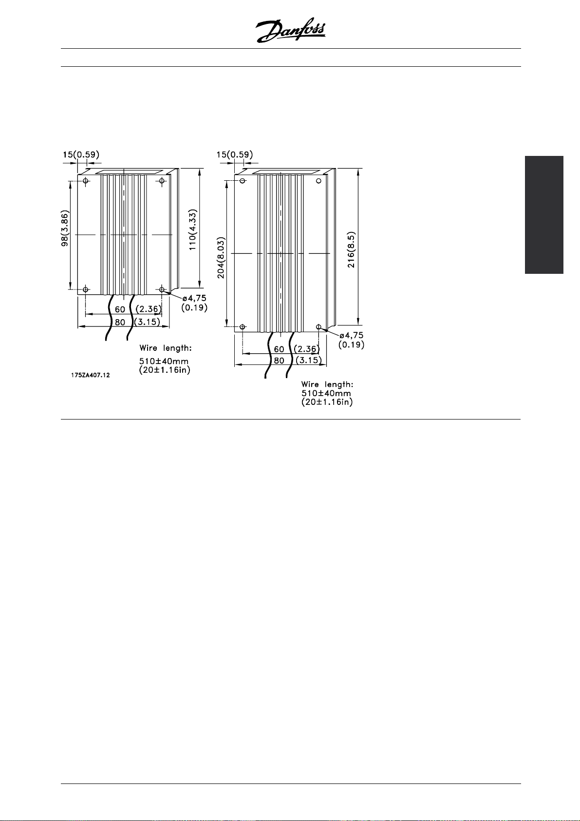
■Dimensions of Flatpack brake resistors
100 W 200 W
2800
Introduction to VLT
MG.28.E9.02 - VLT is a registered Danfoss trademark
29
Page 30
VLT®2800 Series
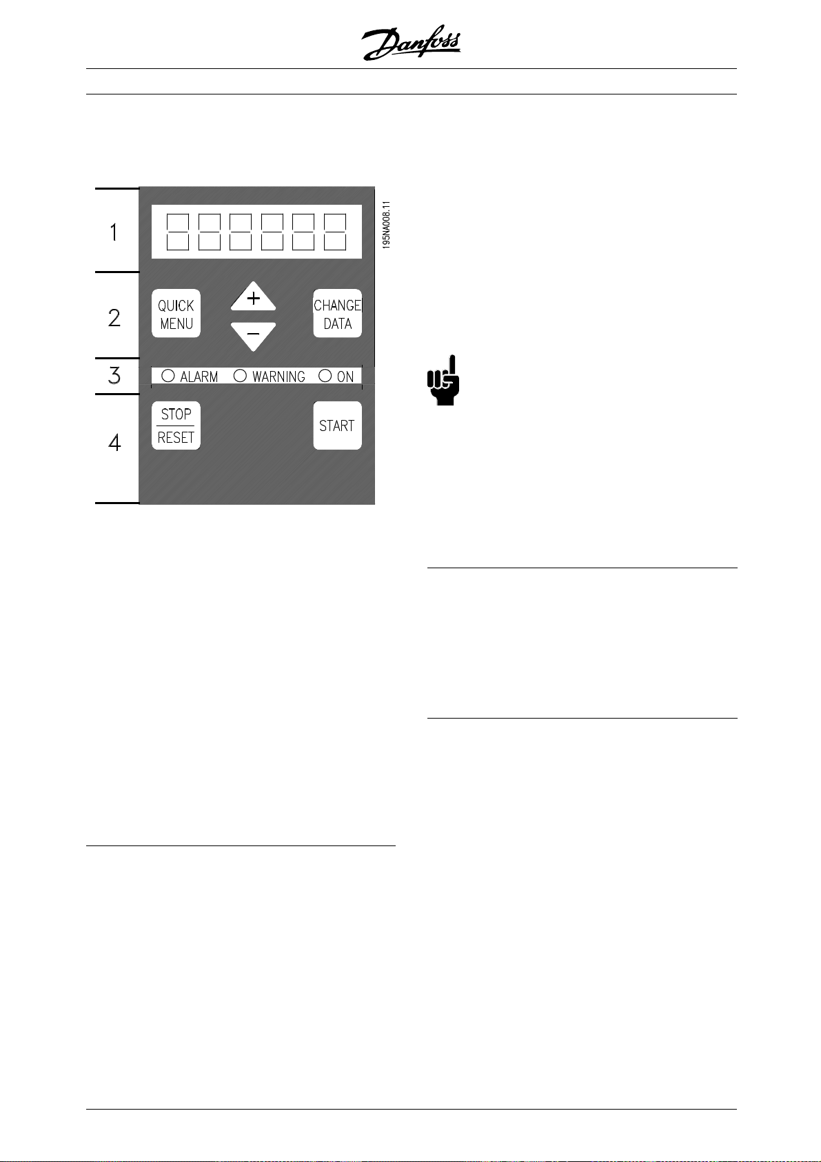
■Control unit
On the front of the frequency converter there
is a control panel.
The control panel is divided into four function groups:
1. Six-digit LED display.
2. Keys for changing parameters and shifting
display function.
3. Indicator lamps.
4. Keys for local operation.
All displays of data are in the form of a six-digit LED
display capable of showing one item of operating
data continuously during normal operation. As a
supplement to the display, there are three indicator
lamps for indicat ion of mains connection (ON),
warning (WARNING) and alarm (ALARM). Most of
the frequency converter’s parameter Setups can be
changed immediately via the control panel, unless
this function has been programmed as Locked [1]
via parameter 018 Lock for data changes.
These keys are also used in Display mode for
selecting the display of an operating value.
The [QUICK MENU] + [+] keys must be
pressed at the same time to give access to all
parameters. See Menu mode.
[STOP/RESET] is used for stopping the
connected motor or for resetting the frequency
converter after a trip.
Can be selected as Active [1] or Not active [0] via
parameter 014 Local stop/reset. In Display mode, the
display will flash if the stop function is ac tivated.
NB!:
If the [STOP/RESET] key is set at Not active
[0] in parameter 014 Loca l stop/reset,and
there is no stop command via the digital
inputs or serial communication, the motor can
only be stopped by disconnecting the mains
voltage to the frequency converter.
[START] is used for starting the frequency
converter. It is always active, but the [START] key
cannot override a stop command.
■Manual initialisation
Disconnect mains voltage. Hold the [QUICK
MENU] + [+] + [CHANGE DATA] keys down while
simultaneously reconnecting the mains voltage.
Release the keys; the frequency converter has now
been programmed for the factory setting.
■Control keys
[QUICK MENU] allows access to the parameters
used for the Quick menu.
The[QUICK MENU] key is also used if a change to
a parameter value is not to be implemented.
See also [QUICK MENU] + [+].
[CHANGE DATA] is used for changing a setting.
The [CHANGE DATA] key is also used for confirming
a change of parameter settings.
[+] / [-] are used for selecting parameters and
for changing parameter values.
30
MG.28.E9.02 - VLT is a registered Danfoss trademark
Page 31

■Display readout states
Display mode
In normal operation, one item of o perating data can
be displayed continuously at the operator’sown
choice. By means of the [+/-] keys the following
options c an be selected in Display mode:
-Outputfrequency[Hz]
- Output current [A]
-Outputvoltage[V]
- Intermediate circuit voltage [V]
-Outputpower[kW]
- Scaled output frequency f
out
x p008
Menu mode
In order to enter the Menu mode [QUICK MENU]
+ [+] must be activated at the same time.
In Menu mode, most of the frequency converter
parameters can be changed. Scroll through the
parameters using the [+/-] keys. While scrolling in the
Menu mode proceeds, the parameter number will flash.
The display shows that the setting in parameter
102 Motor power P
is 0.75. In order to change
M,N
the value of 0.75, [CHANGE D ATA] must first
be activated; the parameter value can then be
changed using the [+/-] keys.
VLT®2800 Series
The display shows that in parameter 128 Motor thermal
protection the selection made is Thermistor trip [2].
Quick menu
Using the [QUICK MENU] key, it is possible to access
the 12 most important parameters of the frequency
converter. After programming, the frequency converter
is in most cases ready for operation. When the
[QUICK MENU] key is activated in Display mode, the
Quick menu starts. Scroll through the quick menu
using the [+/-] keys and change the data values by
first pressing [CHANGE DATA] and then changing
the parameter value with the [+/-] keys.
The Quick menu parameters are:
• Par. 100 Configuration
• Par. 101 Torque characteristic
• Par. 102 Motor power P
• Par. 103 Motor voltage U
• Par. 104 Motor frequency f
• Par. 105 Motor current I
• Par. 106 Rated motor speed n
• Par. 107 Automatic motor adaptation
• Par. 202 Output frequency high limit f
• Par. 203 Reference range
• Par. 204 Minimum reference Ref
• Par. 205 Maximum reference Ref
• Par. 207 Ramp-up time
• Par. 208 Ramp-down time
• Par. 002 Local/remote operation
• Par. 003 Local reference
Parameter 102 - 106 can be read out from
the motor’s nameplate.
M,N
M,N
M,N
M,N
M,N
MAX
MIN
MAX
2800
Introduction to VLT
If for a given parameter the display shows three
dots at the right, it means that the parameter
value has more tha n three d igits. In order to see
the value, activate [CHANGE DATA].
MG.28.E9.02 - VLT is a registered Danfoss trademark
■Hand Auto
During normal operation the frequency converter is
in Auto mode, where the reference signal is given
externally, analog or digital via the control terminals.
However, in Hand mode, it is possible to give the
reference signal locally via the control panel.
31
Page 32

VLT®2800 Series
On the control terminals, the following control signals
will remain active when Hand mode is act ivated:
• Hand Start (LCP2)
• Off Stop (LCP2)
• Auto Start (LCP2)
• Reset
• Coasting Stop Inverse
• Reset and Coasting Stop Inverse
• Quick Stop Inverse
• Stop Inverse
• Reversing
• DC Braking Inverse
• Setup S elect LSB
• Setup S elect MSB
• Thermistor
• Precise Stop Inverse
• Precise Stop/Start
• Jog
• Stop Command Via Serial Comm.
Switching between Auto- and Hand mode:
By activating the [Change Data] key in [Display
Mode], the display will indicate the mode of
the frequency converter.
3. When "107" appears once more with the data
value [0], AM T is complete. Press [STOP/RESET]
to save the motor data.
4. "107" will then continue to flash with the data
value [0]. You can now proceed.
NB!:
VLT 2880-2882 do not have AMT function.
Scroll up/down in order to switch to Hand mode:
When the frequency converter is in Hand mode
thereadoutwillbelike:
and the reference can be changed by using
the following keys:
NB!:
Please note, that parameter 020 may
block the choice of mode.
Automatic motor tuning
Automatic motor tuning (AMT) is performed as follow s:
1. In parameter 107 Automatic motor tuning
select data value [2]. "107" will now flash,
and "2" will not flash.
2. AMT is activated by pressing start. "107" will
now flash and dashes will move from left to
right in the data value field.
32
MG.28.E9.02 - VLT is a registered Danfoss trademark
Page 33

VLT®2800 Series
■The LCP 2 Control unit, option
unless this function has been programmed as Locked
[1] via parameter 018 Lock for data changes.
■Control keys for parameter Setup
The control keys are divided into functions, in
such a way that the keys between the display
and the indicator lamps are used for parameter
Setup, including selection of the display’sview
mode during normal operation.
2800
Introduction to VLT
[DISPLAY/STATUS] is used to select the display’s
view mode or to change back to Display mode
from either Quick Menu or Menu mode.
The frequency converter can be combined with
an LCP control unit (Local Control Panel - LCP 2)
which makes up a complete interface for op
and programming of the frequency converter. The
LCP 2 control unit can be attached up to three
metres from the frequency converter,
front panel, using an accessory kit.
The control panel is divided into five functional groups:
1. Display.
2. Keys used to cha nge the display fun
3. Keys used to change the programme parameters.
4. Indicator lamps.
5. Local control keys.
All data is displayed via a 4-line
display, which during normal operation will be able
to continuously display 4 items of operating data
and 3 operating modes. D uring p
information needed for quick, effective parameter
setup of the frequency converter will be displayed. As
a supplement to the displ
lamps for voltage (ON), warning (WARNING) and alarm
(ALARM). All frequency converter parameter Setups
can be changed immedia
ay, there are three indicator
tely from the control panel,
alphanumeric
rogramming all
eration
e.g. on a
ction.
[QUICK MENU] provides access to the parameters
used in the Quick Menu. It is possible to switch
between Quick Menu and Menu mode.
[MENU] givesaccesstoallparameters. Itispossible
to switch between Menu mode and Quick Menu.
[CHANGE DATA] is used to change a parameter that
has been selected either in Menu mode or Quick Menu.
[CANCEL] is used if a change to the selected
parameter is not to be implemented.
[OK] is used to confirm a change to a
selected parameter.
[+ / -] are used for selecting parameters and
for changing parameter values.
These keys are also used in Display mode to switch
between the readouts of operating variables.
[< >] are used for selecting parameter group and to
move the cursor when changing a numerical va lue.
MG.28.E9.02 - VLT is a registered Danfoss trademark
33
Page 34

VLT®2800 Series
■Indicator lamps
At the bottom of the control panel are a red
alarm lamp, a yellow warning lamp and a
green voltage indicator lamp.
If certain threshold values are exceeded, the alarm
and/or warning lamp are activated, while a status
or alarm text is shown on the display.
NB!:
The voltage indicator lamp is activated when
voltage is connected to the frequency converter.
■Local control
[STOP/RESET] is used for stopping the motor
connected or for resetting the frequency converter
after a drop-out (trip). Can be set to active or
inactive via parameter 014 Local stop.
If stop is activated Display line 2 will flash.
NB!:
If an external stop function is not selected and
the [STOP/RESET] key is set to inactive, the
motor can only be stopped by disconnecting
the voltage to the motor or the frequency converter.
[JOG] changes the output frequency to a preset
frequency while the key is held down. Can be set to
active or inactive via parameter 015 Local jog.
NB!:
If the local control keys are set to inactive,
these will both become active when the
frequency converter is set to Local control
and Remote control via parameter 002 Local/remote
operation, with the exception of [FWD/REV], which
is only act ive in Local control.
■Display mode
195NA113.10
VAR 1.1 VAR 1.2 VAR 1.3
VAR 2
STATUS
SETUP
1
In normal operation, up to 4 different display data
items can optionally be shown continuously: 1,1,
1,2, 1,3 and 2. The present operation status or
alarms and warnings that have been generated are
displayed in line 2 in the form o f a number.
In the event of alarms this is displayed in lines
3and4withexplanatorytext.
A warning will appear flashing in line 2 with
explanatory text in line 1. The active Setup
will also appear on the display.
The arrow indicates the selected direction of rotation.
Here the frequency converter shows that it has
an act ive reversing signal. The body of the arrow
will disappear if a stop command is given, or if the
output frequency drops below 0.1 Hz.
The bottom line displays the frequency transformer’s
status. The scrollbar shows which operating values
can be displayed in lines 1 and 2 in Display mode.
Changes are made using the [+ / -] keys.
[FWD / REV] changes the direction of rotation of
the motor, which is indicated by means of the arrow
on the display. Can be set to active or inactive via
parameter 016 Local reversing.The[FWD/REV]key
is only active when parameter 002 Local/remote
operation is set to Local control.
[START] is used to start the frequency converter. Is
always active, but cannot override a stop command.
34
MG.28.E9.02 - VLT is a registered Danfoss trademark
Page 35

VLT®2800 Series
Operating data Unit
Resulting reference [%]
Resulting reference [unit]
Feedback [unit]
Output frequency [Hz]
Output frequency x scaling [-]
Motor current [A]
Torque [%]
Power [kW]
Power [HP]
Motor voltage [V]
DC link voltage [V]
Thermal load motor [%]
Thermal load [%]
Hours run [hours]
Digital input [binary]
Pulse reference [Hz]
External reference [%]
Status word [hex]
Heatsink temperature [°C]
Alarm word [hex]
Control word [hex]
Warning word [hex]
Extended status word [hex]
Analogue input 53 [V]
Analogue input 60 [mA]
Three operating data items can be shown in the
first display line, and one operating variable can be
shown in the second display line. Is programmed via
parameters 009, 010, 011 and 012 Display readout .
24.3% 30.2% 13.8A
50.0 Hz
MOTOR IS RUNNING
In this mode, all data values for four operating
data items with any pertaining units are shown,
see table. In the example, the following have been
selected: Frequency, Reference, Torque and Current
as readout in the first and second line.
Display mode III:
This display mode is called up as long as the [DISPLAY
/ STATUS] key is held down. When the key is released
it switches back to Display mode II, unless the key is
held down for less than approx. 1 sec., in which case
the system always reverts to Display mode I.
REF% TORQUE CURR A
50.0 Hz
MOTOR IS RUNNING
Here you can read out the parameter names and
units for operating data in the first and second lines.
Line 2 in the display remains unchanged.
SETUP
1
2800
Introduction to VLT
■Display modes
The LCP control unit has different display
modes, which depend on the mode selected
for the frequency converter.
DisplaymodeI:
This display mode is standard after startup
or initialisation.
FREQUENCY
50.0 Hz
MOTOR IS RUNNING
Line 2 shows the data value of an operating data item
with unit, and line 1 contains a text that explains line
2. In the example, Frequency has b een selected as
readout via parameter 009 Large display readout.In
normal operation, another variable can be entered
immediately using the [+ / -] keys.
Display mode II:
Switch between Display modes I and II is performed
by briefly pressing the [DISPLAY / S TATUS] key.
MG.28.E9.02 - VLT is a registered Danfoss trademark
35
Page 36

DisplaymodeIV:
This display mode can be called up d uring operation
if a change has to be made in another Setup without
stopping the frequency converter. This function is
activated in parameter 005 Programming Setup.
24.3% 30.2% 13.8A
SETUP
50.0 Hz
MOTOR IS RUNNING
12
Here the programming Setup number 2 will flash
to the right of the active Setup.
■Parameter Setup
A frequency converter’s comprehensive work area can
be accessed via a large number of parameters, making
it possible to adapt its functionality for a specific
application. To provide a better over view of the many
parameters, there is a choice of two programming
modes - Menu mode and Quick Menu mode. The
former provides access to all parameters. The latter
takes the user through the parameters, which make
it possible to start operating the frequency converter
in most c ases, in accorda nce with the Setup made.
Regardless of the mode of programming, a change
of a parameter will take effect and be visible both in
the Menu mode and in the Quick menu mode.
Structure for Quick menu m ode v Menu mode
In addition to having a name, each parameter is linked
up with a number which is the same regardless of
the programming mode. In Menu mode, paramet
will be split into groups, with the first digit ( left)
of the parameter number indicating the group
number of the parameter in question.
VLT®2800 Series
■Quick m enu with LCP 2 control unit
Start Quick Setup by pressing the [QUICK MENU] key,
which will bring out the following display values:
QUICK MENU X OF Y
50.0 Hz
001 LANGUAGE
ENGLISH
At the bottom of the display, the parameter number
and name are given together with the status/value
of the first parameter under the Quick menu. The
first time the [QUICK MENU] key is pressed after
the unit has been switched on, the readouts always
start in pos. 1 - see table below.
Pos. Parameter no. Unit
1 001 Language
2 102 Motor power [kW]
3 103 Motor voltage [V]
4 104 Motor frequency [Hz]
5 105 Motor current [A]
6 106 Rated motor speed [rpm]
7 107 AMT
8 204 Minimum reference [Hz]
9 205 Maximum reference [Hz]
10 207 Ramp-up t ime [sec]
11 208 Ramp-down time [sec]
12 002 Local/remote operat ion
13 003 Local reference [Hz]
■Parameter selection
Menu mode is started by pressing the [MENU] key,
which produces the following readout on the display:
FREQUENCY
ers
50.0 Hz
0 KEYB.&DISPLAY
SETUP
1
• Using the [QUICK MENU] key, it is possibl
eto
get acc ess to the most important parameters
of the frequency converter. After programming,
the frequency converter is in most
cases ready
for operat ion. Scroll through the Quick menu
using the [+ / -] keys and change the data values
by pressing [CHANGE DATA] + [OK
].
• The Menu mode allows choosing and changing
all parameters as required. However, some
parameters will be "shaded
off", depending on the
choice in parameter 100 Configuration .
36
Line 3 on the display shows the parameter
group number and name.
In Menu mode, the parameters are divided
into groups. Selection of parameter group is
effected using the [< >] keys.
The following parameter groups will be accessible:
Group no. Parameter group
0 Operation & Display
1Load&Motor
2 References & Limits
3 Inputs & Outputs
4 Special functions
5 Serial communication
6 Technical functions
MG.28.E9.02 - VLT is a registered Danfoss trademark
Page 37

VLT®2800 Series
When the required parameter group has been
selected, each parameter can be chosen by
means of the [+ / -] keys:
FREQUENCY
50.0 Hz
001 LANGUAGE
ENGLISH
The 3 rd line of the display shows the parameter
number and name, while the status/value of the
selected parameter is shown in line 4.
Changing data
Regardless of w h ether a parameter has been
selected under the Quick menu or the Menu mode,
theprocedureforchangingdatawillbethesame.
Pressing the [CHANGE DATA] key gives access
to changing the selected parameter, following
which the und erlini n g in line 4 will flash on the
display. The procedure for changing data depends
on whether the selected parameter represents a
numerical data value or a text value.
Changing a data value
If the selected parameter is a text value, the text
value is changed by means of the [+ / -] keys.
The chosen digit is indicated by the digit flashing. The
bottom display line shows the data value that will be
entered (saved) when signing off with [OK].
■ M anual initialisation
NB!:
Manual initialisation is n
the LCP 2 175N0131 control unit. It is,
however, possible to perform an initialisation
via par. 620 Operation mode:
The following parameters are not set to zero when
initialising via par. 620 Operation mode.
- par. 500 Address
- par. 501 Baud rate
- par. 600 Operating hours
- par. 601 Hours run
- par. 602 kWh counter
- par. 603 Number of power-ups
- par. 604 Number of overtemperatures
- par. 605 Number of overvoltages
- par. 615-617 Fault log
ot possible on
2800
Introduction to VLT
FREQUENCY
50.0 Hz
001 LANGUAGE
ENGLISH
The bottom display line will show the value that w ill be
entered (saved) when acknowledgment is given [OK].
Changeofnumericdatavalue
If the selected parameter is represented by a numerical
data value, a digit is first chosen using the [< >] keys.
FREQUENCY
50.0 Hz
130 START FREQUENCY
09.0 HZ
The selected digit can then be changed infinitely
variably using the [+ / -] keys:
FREQUENCY
50.0 Hz
130 START FREQUENCY
10.0 HZ
SETUP
1
SETUP
1
MG.28.E9.02 - VLT is a registered Danfoss trademark
37
Page 38

■Mechanical dimensions
The drawings below give the mechanical dimensions.
All dimensions are in mm.
VLT 2803-2815 200-240 Volt
VLT 2805-2815 380-480 Volt
VLT®2800 Series
VLT 2840 200-240 Volt
VLT 2855-2875 380-480 Volt
VLT 2822 200-240 Volt
VLT 2822-2840 380-480 Volt
VLT 2880-82 380-480V
38
MG.28.E9.02 - VLT is a registered Danfoss trademark
Page 39

■Motor coils (195N3110)
■RFI 1 B filter (195N3103)
VLT®2800 Series
■Terminal cover
The drawing below gives the dimensions for NEMA
1 terminal covers for VLT 2803-2875.
Dimension ’a’ depends on the unit type.
Installation
MG.28.E9.02 - VLT is a registered Danfoss trademark
39
Page 40

■IP 21 solution
VLT®2800 Series
Dimensions
Type Code number A B C
VLT 2803-2815 200-240 V, VLT 2805-2815 380-480 V 195N2118 47 80 170
VLT 2822 200-240 V, VLT 2822-2840 380-480 V 195N2119 47 95 170
VLT 2840 200-240 V, VLT 2855-2875 380-480 V 195N2120 47 145 170
VLT 2880-2882 380-480 V 195N2126 47 205 245
■EMC filter for long motor cables
192H4719
40
MG.28.E9.02 - VLT is a registered Danfoss trademark
Page 41

VLT®2800 Series
192H4720
Installation
192H4893
MG.28.E9.02 - VLT is a registered Danfoss trademark
41
Page 42

VLT®2800 Series
■Mechanical installation
Please pay attention to the requirements
that apply to installation.
The frequency converter is
cooled by means of air c irculation. For the unit to be
able to release its cooling air, the minimum free
distance above and below the unit must be m
100 mm . To protect the unit from overheating, it
must be ensured that the am bient temperature does
not rise above the max. temperature stated for the
frequency converter and that the 24-hour average
temperature is not exceeded. The max. temperature
and 24-hour average can be seen in General technical
data. If the ambient temperature is in the range of 45
°C - 55 °C, derating of the frequency converter
is to be carried out. See Derating for ambient
temperature. Pleasenotethattheservicelifeofthe
frequency converter will be reduced if no allowance is
made for the derating for ambient temperature.
■Side-by-side
All VLT 2800 units can be installed side-by-side
and in any position, as the units do not require
ventilation on the side.
inimum
■Integration
All units with enclosure IP 20 must be integrated
in cabinets and panels. IP 20 is not suitable
for remote mount ing. In some countries, e.g.
in the USA, units with enclosure NEMA 1 are
approved for remote mounting.
■Spacing for mechanical installation
All units require a minimum of 100 mm air between
other components and vents of the enclosure.
NB!:
With the IP 21 solution all units require
a minimum of 100 mm air on each
side. This means that side-by-side
mounting is n
ot allowed.
42
MG.28.E9.02 - VLT is a registered Danfoss trademark
Page 43

VLT®2800 Series
■High voltage warning
The voltage of the frequency converter
is dangerous whenever the equipment is
connected to mains. Incorrect installation
of the motor or frequency converter may cause
damage to the equipment, serious injury or death.
Comply with the instructions in this manual, as well as
national and local rules and safety regulations.
Touching the electrical parts may b e fatal - even after
the equipment has been disconnected from mains:
Wait at least 4 minutes for current dissipate.
NB!:
It is the responsibility of the user or installer
to ensure correct earthing and protection in
accordance with national and local standards.
■Earthing
Comply with the following at installation:
• Safety earthing: The drive has a high leakage
current and must be earthed properly for safety.
Follow all local safety regulations.
• High frequency earthing: Keep earthing
connections as short as possible.
When being placed in cable trays, sensitive cables
may not be placed in the same cable tray as the
motor cable. If signal cables run across power
cables, this is done at an angle of 90 degrees.
Remember that all noise-filled inlet and outlet cables
to a cabinet must be screened/armoured.
See also EMC-compliant electrical installation.
■Screened/armoured cables
The screen must have low HF impedance, which is
achieved by a braided screen of copper, aluminium or
iron. Screen reinforcement intended for mechanical
protection, for example, is not suitable for EMC-correct
installation. See also Use of EMC -correc t cables.
■Extra protection
RCD relays, multiple protective earthing or earthing
can be used as extra protection, provided that local
safety regulations are complied w ith. In the case of an
earth fault, a DC content may develop in the faulty
current. Never use an RCD (ELCB relay), type A, as
it is not suitable for DC faulty currents. If RCD relays
are used, local regulations must be complied with.
If RCD relays are used, they must be:
Installation
Connect all earthing systems to ensure the lowest
possible conductor impedance. The lowest possible
conductor impedance is achieved by keeping the
conductor as short as possible and by grounding with
the greatest possible surface area. If multiple drives
are installed in a cabinet, the cabinet backplate, which
must be made of metal, should be used as a joint
earth reference plate. The drives must be fitted to the
backplate at the lowest possible impedance.
To achieve low impedance, connect the drive to the
backplate with the drive fastening bolts. Remove
all paint from the contact points.
■Cables
The control cable and the mains cable should be
installed separately from motor cables to prevent
noisetransfer. Asaruleadistanceof20cmis
sufficient, but it is recommended that the distance
is as great as possible, particula rly when cables are
installed in parallel over large distances.
- Suitable for protecting equipment with a DC content
in the faulty current (3-phase bridge rect ifier).
- Suitable for a pulse-shaped, brief discharge
on power-up.
- Suitable for a high leakage current.
N must be connected before L1 for single phase 200
V reduced leakage current units (type code R4).
■High voltage test
A high voltage test can be performed by
short-circuitingterminalsU,V,W,L1,L2andL3,
and applying max. 2160 V DC in 1 sec. between
this short-circuit and terminal 95.
For sensitive signal cables such as telephone or data
cables the greatest possible distance is recommended.
Please note that the required distance depends on the
installation and the sensitivity of the signal cables, and
that for this reason exact values cannot be given.
MG.28.E9.02 - VLT is a registered Danfoss trademark
43
Page 44

■EMC-correct electrical installation
General points to be observed to ensure
EMC-correct electrical installation.
- Use only screened/armoured motor cables and
screened/armoured control cables.
- Connect the screen to earth at both ends.
- Avoid installation with twisted screen ends (pigtails),
since this ruins the screening effect at high
frequencies. Use cable clamps instead.
VLT®2800 Series
- It is important to ensure good electrical contact from
the installation plate through the installation screws
to the metal cabinet of the frequency c onverter.
- Use starwashers and galvanically conductive
installation plates.
- Do not use unscreened/unarmoured motor
cables in the installation cabinets.
The illustration below shows EMC -c orrect electrical
installation, in which the frequency converter has been
fitted in an installation cabinet and connected to a PLC.
44
MG.28.E9.02 - VLT is a registered Danfoss trademark
Page 45

VLT®2800 Series
■Use of EMC compliant cables
In order to comply with requirements for EMC immunity
of the control cables and EMC emissions from the
motor cables screened/armoured cables must be used.
The ability of a cable to reduce the amount of ingoing
and outgoing radiation of electric noise depends
on the transfer impedance (Z
). The screen of a
T
cable is normally designed to reduce the transfer of
electric noise, and a screen with a lower Z
effective than a screen with a higher Z
is rarely stated by cable manufacturers, but it
Z
T
is often possible to estimate Z
by looking at and
T
is mor e
T
.
T
assessing the physical design of the cable.
can be assessed on the basis of the following factors:
Z
T
- the contact resistance between the individual
screen conductors.
- Screen coverage, i.e. the physical area of the
cable covered by the screen. Is often stated as a
percentage and should be no less than 85%.
- The screen type, i.e. braided or twisted pattern. A
braided pattern or closed pipe is recommended.
Installation
MG.28.E9.02 - VLT is a registered Danfoss trademark
45
Page 46

■Earthing of screened/armoured control cables
In general control cables must be screened/armoured,
and the screen must be co nnected to the unit’s metal
cabinet with a cable clamp at each end.
The drawing below shows the correct way to perform
the earthing, and what to do whe n in doubt.
1. Correct earthing
Control cable s and cables for serial
communication must be attached with cable
clamps at both ends to ensure maximum
possible electrical contact.
2. Incorrect earthing
Do not use twisted screen ends that
are plaited together (pigtails), as these increase
screen impedance at higher frequencies.
3. Protection with respect to earth
potential between PLC and VLT
If the earth potential between the VLT
frequency converter and the PLC (etc.) is different,
electric noise may occur that will disturb the whole
system. This problem can be solved by fitting an
equalising cable, to be placed next to the co ntrol
cable. Minimum cable cross-section: 16 mm
4. In the event of a 50/60 Hz earth loop
If ver y long c ontrol cables are used, 50/60 Hz
earth l oops can arise, and these can interfere
with the whole system. This problem is resolved
by attaching one e nd of the screen to the earth
via a 100 nF capacitor (short pin length).
VLT®2800 Series
2
.
46
MG.28.E9.02 - VLT is a registered Danfoss trademark
Page 47

■Diagram
VLT®2800 Series
* Integrated 1A RFI filter and brak
** VLT 2803-2815 200-240 V is not supplied
with intermediate circuit coils.
eisanoption.
Installation
MG.28.E9.02 - VLT is a registered Danfoss trademark
47
Page 48

■Electrical installation
See also the section Brake Connect i on.
VLT®2800 Series
VLT 2803-2815 200-240 V, 2805-2815 380-480 V
48
VLT 2822 200-240 V, 2822-2840 380-480 V
MG.28.E9.02 - VLT is a registered Danfoss trademark
Page 49

VLT®2800 Series
VLT 2840 200-240 V, 2855-2875 380-480 V
Installation
VLT 2880-2882 380-480 V
Please note that the units will be supplied
with two bottom plates; one for metric glands
and one for conduits.
MG.28.E9.02 - VLT is a registered Danfoss trademark
49
Page 50

VLT®2800 Series
■Safety clamp
If the galvanic isolation (PELV) between
control terminals and high-voltage terminals
is to be maintained, the accompanying
safety c lamp must be fitted to VLT 2803-2815,
200-240 V, and VLT 2805-2815, 380-480 V.
■Pre-fuses
For all unit types, external pre-fuses must be fitted in the
mains supply to the frequency converter. For UL/cUL
applications with a mains voltage of 200-240 Volt, use
pre-fuses type Bussmann KTN-R (200-240 Volt) or
Ferraz Shawmut type ATMR (max. 30A). For UL/cUL
applications with a mains voltage of 380-480 Volt, use
pre-fuses type Bussmann KTS-R (380-480 Volt). See
Technical data for correct dimensioning of pre-fuses.
■Mains connection
Please note that at 1 x 220-240 V olt the neu tral wire
must be attached to terminal N
wire must be connected to terminal L1
and the phase
(L2)
(L1)
.
400-Volt units with RFI-filters may not b e
connected to mains supplies in which the
voltage between phase and earth is more
than 300 Volts. Please note that for the IT mains
and the del ta earth the mains voltage can exceed
300 Volts between phase and earth. Units with type
code R5 can be connected to mains supplies with
up to 400 V between phase and earth.
See Technical data for correct dimensioning of
cable cross-section. See also the section entitled
Galvanic isolation for further details.
■Motor connection
Connect the motor to terminals 96, 97, 98.
Connect earth to terminal 99.
No. 96 97 98 M otor voltage 0-100% of
mains voltage.
UVW 3wiresofmotor
U1W2V1U2W1V26 wires out of motor, Delta
connected
U1 V1 W1 6 wires out of motor, Star
connected
U2, V2, W2 to be
interconnected separely
(optional terminal block)
No. PE Earth connection
No. N
(L2)L1(L1) (L3)
NL1
No. 95 Earth connection
No. N
(L2)L1(L1) (L3)
L2 L1 L3
No. 95 Earth connection
No. 91 92 93 Mains voltage 3 x 380-480 V
L1 L2 L3
No. 95 Earth connection
Mains voltage 1 x 220-240 V
Mains voltage 3 x 220-240 V
NB!:
Please check that the mains voltage fits the
mains voltage of the frequency converter, which
can be seen from the nameplate.
50
See Technical data for correct dimensioning
of cable cross-section.
All types of three-phase asynchronous standard
motors can be connected to a frequency converter.
Normally, small motors are star-connected (230/400
/ Y). Large motors are delta-connected (400/690
V,
/ Y). The correct connection mode and voltage
V,
can be read from the motor nameplate.
NB!:
In motors without phase insulation paper,
an LC filter should be fitted on the output
of the frequency converter.
MG.28.E9.02 - VLT is a registered Danfoss trademark
Page 51

■RFI switch
ains supply isolated from earth:
M
If the frequency converter is supplied from an isolated
mains source ( IT mains) or TT/TN-S mains with
grounded leg, the RFI switch is recommended
to be turned off (OFF). For further reference, see
IEC 364-3. In case optimum EMC performance is
needed, parallel motors are c onnected or the motor
cable length is above 25 m, it is recommended
to set the switch in ON position.
In OFF position, the internal RFI capacities (filter
capacitors) between the chassis and the intermediate
circuit are cut off to avoid damage to the intermediate
circuit and to reduce the earth capacity currents
(according to IEC 61800-3).
Please also refer to the application note VLT on
IT mains, MN.90.CX.02. It is important to use
isolation monitors that are capable for use together
with power electronics (IEC 61557-8).
VLT®2800 Series
■Direction of motor rotation
The factory setting is for clockwise rotation
with the frequency converter transformer output
connected as follows:
Terminal 96 connected to U-phase.
Terminal 97 connected to V-phase.
Terminal 98 conne cted to W-phase.
The direction of rotation can be c hanged by switching
two phases on the motor terminals.
Installation
NB!:
The RFI switch is not to be operated with
mains connected to the unit. Check that
the mains supply has been disconnected
before operating the RFI switch.
NB!:
The RFI switch disconnects the capacitors
galvanically from ground.
The switch Mk9, placed next to terminal 96, should
be removed to disconnect the RFI-filter.
The RFI switch is only available on VLT 2880-2882.
■Parallel connection of motors
The frequency converter is a ble to control several
motors connected in parallel. If the m otors are
to have different rpm values, use motors with
different rated rpm values. Motor rpm is changed
simultaneously, which means that the ratio between
the rated rpm values is maintained across the range.
The total current consumption of the motors is
not to exceed the maximum rated output current
for the frequency converter.
I
INV
MG.28.E9.02 - VLT is a registered Danfoss trademark
51
Page 52

VLT®2800 Series
Problems may arise at the start and at low rpm
values if the motor sizes are widely different. This
is because the small motors’ relat ively high ohmic
resistance in the stator calls for a higher voltage
at the start and at low rpm values.
In systems with motors connected in parallel, the
electronic thermal rela y (ETR) of the frequency
converter cannot be used as motor protection
for the individual motor. For this reason further
motor protection must be used, e.g. thermistors in
each motor or an individual thermal relay. (Circuit
breakers are not suitable as protection).
NB!:
Parameter 107 Automatic motor adaption, AMT
cannot be used when motors are connected
in parallel. Parameter 101 Torque characteristic
must be set to Special motor characteristics [8]
when motors are connected in parallel.
■Motor cables
See Technical data for correct dimensioning of motor
cable cross-section and length. Always comply with
national and local regulations on cable cross-section.
NB!:
If an unscreened/unarmoured cable is used,
some EMC requirements are not complied with,
see EMC test results in the Design Guide.
If the EMC specifications regarding emission are
to be complied with, the motor cable must be
screened/armoured, unless otherwise stated for the
RFI filter in question. It is important to keep the motor
cable as short as possible so as to reduce the noise
level and leakage currents to a minimum. The motor
cable screen must be connected to the metal cabinet
of the frequency converter and to the metal cabinet of
the motor. The screen connections are to be made
with the biggest possible surface area (cable clamp).
This is enabled by different installation devices in
different frequency converters. Mounting with twisted
screen ends (pigtails) is to be avoided, since these
spoil the screening effect at high frequencies. If it
is necessary to break the screen to install a motor
isolator or motor relay, the screen must be cont inued
at the lowest possible HF impedance.
protection has been set for ETR T rip and parameter
105 Motor current, I
has been programmed to
M, N
the rated motor current (see motor nameplate).
■Brake connection
No. 81 82 Brake resistor
R- R+ terminals
The connection cable to the brake resistor must
be screened/armoured. C onnect the screen to the
metal cabinet of the frequency c
onverter and to the
metal cabinet of the brake resistor by means of
cable clamps. Dimension the cross-section of the
brake cable to match the bra
See the Design Guide fo
ke torque.
r dimensioning
of brake resistors.
NB!:
Please note that voltages up to 850 V
DC occur on the te
rminals.
■Earth connection
As leak current to the earth is higher than 3.5 mA, the
frequency conve
rter must always be earthed according
to prevailing national and local regulations. To
guarantee that the earth cable has a good mechanical
connection
must be at least 10 mm
to terminal 95, the cable cross section
2
or 2 rated earth wires
that are terminated separately. To increase safety
you can i
nstall an RCD (Residual Current Device),
which guarantees that the frequency converter trips
when leak current becomes too high. See also
pplication Note MN.90.GX.02.
RCD A
■Motor thermal protection
The electronic thermal relay in UL-approved frequency
converters has received the UL-approval for single
motor protection, when parameter 128 Motor thermal
52
MG.28.E9.02 - VLT is a registered Danfoss trademark
Page 53

VLT®2800 Series
■Load sharing
Load sharing provides the facility to connect several
frequency converters’ DC intermediate circuits.
This requires that the installation is extended using
extra fuses and AC coils (see drawing below).
For load sharing parameter 400 Brake function
must be set to Load sharing [5].
Note that voltage le vels of up to 850 V DC
may occur between terminals 88 and 89.
■Tightening Torque, Power Terminals
Power and earth terminals must be tightened
with the following torques:
VLT Terminals Torque [Nm]
Power mains brake 0.5-0.62803-
2875
Earth 2-3
Power mains brake 1.2-1.52880-
2882
Earth 2-3
Use 6.3 mm Fa ston Plugs for DC (Load Sharing).
Contact Danfoss or see instructions no. MI.50.NX.02
for further information.
No. 88 89 Loadsharing
-+
Installation
NB!:
This application is only for lift ing/low ering
without a counterbalance.
■Access to control terminals
All terminals to the control cables are located
underneath the protective plate on the front of the
frequency converter. Remove the protective plate
by pulling it downwards (see drawing).
■Control of mechanical brake
In lifting/low ering applications you need to be able
to control an electromagnetic brake. The brake
is controlled using a relay output or digital output
(terminal 46). The output must be kept closed
(voltage-free) for the period of time during which the
frequency converter is not able to ’support’ the m otor,
for example due to the load being too great. Select
Mechanical brake control in parameter 323 or 341
for applications with an electromagnetic brake.
When the output frequency exceeds the brake cut
out value set in par. 138, the brake is released
if the motor current exceeds the preset value i n
parameter 140. The brake is engaged when the
output frequency is less than the brake engaging
frequency, which is set in par. 139.
If the frequency converter is placed at alarm status
or in an overvoltage situation the mechanical
brake is cut in immediately.
MG.28.E9.02 - VLT is a registered Danfoss trademark
53
Page 54

VLT®2800 Series
■Electrical installation, control cables Control cables must be screened/armoured. The
screen must be connected to the frequency converter
chassis by m eans of a clamp. N ormally, the screen
must also be connected to the chassis of the
controlling unit (use the instructions for the unit in
question). In connection with very long control cables
and analogue signals, in rare cases depending on
the i nstallation, 50/60 Hz earth l oops may occur
because of noise transmitted from mains supply
cables. In this connection, it may be necessary
to break the screen and possibly insert a 100 nF
capacitor between the screen and the chassis.
54
MG.28.E9.02 - VLT is a registered Danfoss trademark
Page 55

VLT®2800 Series
■Tightening torques, control cables
Control wires must be connec ted with a tightening
torque of 0.22-0.25 Nm.
■Electrical installation, control terminals
See section entitled Earthing of screened/armoured
control cables in the Design Guide for the correct
termination of control cables.
No. Function
01-03 Relay outputs 01-03 can be used for
indicating status and alarms/warnings.
12 24 V DC voltage supply.
18-33 Digital inputs.
20, 55 Common frame for input
and o utput terminals.
42 Analog ou tp ut for displaying frequency,
reference, current or torque.
1
46
Digital output for displaying status,
warnings or alarms, as well as
frequency output.
50 +10 V DC supply
voltage for potentiometer or thermistor.
53 Analogue voltage input 0 - 10 V DC.
60 Analogue current input 0/4 - 20 mA.
1
67
+5VDCsupplyvoltage
to Profibus.
68,
69
70
RS 485, Serial communication.
1
1
Frame for terminals 67, 68 and 69.
Normally this terminal is not to be used.
NB!:
Please note that the cable jacket for the
relay must cover the first row of control
card terminals - otherwise the galvanic
isolation (PELV) cannot be maintained. Max. cable
diameter: 4 mm. See drawing.
■Switches 1-4
The dip sw itch is only on the control card with
Profibus DP communication.
The switch position shown is the factory setting.
Installation
Switches 1 and 2 are used as cable termination for the
RS 485 interface. If the frequency converter is located
as the first or last unit in the bus system, switches
1 and 2 must be ON. On the remaining frequency
converters, switches 1 and 2 must be OFF.
Switches 3 and 4 are not applied.
■VLT Software Dialog
Connection to terminals 68-70 or
Sub D:
-PIN3GND
- PIN 8 P-RS 485
-PIN9N-RS485
1. The terminals are not valid for DeviceNet. See the
DeviceNet manual, MG.90.BX.YY for further details.
■Relay connection
See parameter 323 Relay output for programming
of relay output.
Nr. 01 - 02 1 - 2 make (normally open)
01 - 03 1-3break(normallyclosed)
MG.28.E9.02 - VLT is a registered Danfoss trademark
■Sub D plug
An LCP 2 control unit can be connected to the Sub D
plug on the control card. Ordering number: 175N0131.
LCP control unit with ordering number 175Z0401
is not to be connected.
55
Page 56

■Connection examples
■Start/stop
Start/stop using terminal 18 and coasting
stop using terminal 27.
Par. 302 Digital input = Start [7]
Par. 304 Digital input = Coasting stop inverted [2]
For Precise start/stop the following settings are made:
Par. 302 Digital input = Precise start/stop [27]
Par. 304 Digital input = Coasting stop inverted [2]
VLT®2800 Series
■Speed up/down
Speed up/down using terminals 29/33.
Par. 302 Digital input = Start [7]
Par. 303 Digital input = Freeze reference [14]
Par. 305 Digital input = Speed up [16]
Par. 307 Digital input = Speed down [17]
■Potentiometer reference
Voltage reference via a potentiometer.
■Pulse start/stop
Pulse start using terminal 18 and pulse stop
using terminal 19. In addition, the jog frequency
is act ivated via terminal 29.
Par. 302 Digital input = Pulse start [8]
Par. 303 Digital input = Stop inverted [6]
Par. 304 Digital input = Coasting stop inverted [2]
Par. 305 Digital input = Jog [13]
Par. 308 Analog input = Reference [1]
Par. 309 Terminal 53, min. scaling =0Volt
Par. 310 Terminal 53, ma x. scaling =10Volt
■Connection of a 2-wire transmitter
Connection of a 2-wire transmitter as feedback
to terminal 60.
56
Par. 314 Analog input = Feedback [2]
Par. 315 Terminal 60, min. scaling =4mA
Par. 316 Terminal 60, max. scaling =20mA
■4-20 mA reference
4-20 mA reference on terminal 60 and speed
feedback signal on terminal 53.
MG.28.E9.02 - VLT is a registered Danfoss trademark
Page 57

Par. 100 Configuration = Speedclosedloop[1]
Par. 308 Analog input = Feedback [2]
Par. 309 Terminal 53, min. scaling =0Volt
Par. 310 Terminal 53, max. scaling =10Volt
Par. 314 Analog input = Reference [1]
Par. 309 Terminal 60, min. scaling =4mA
Par. 310 Temina l 60, max. scaling =20mA
■ 50 Hz anti-clockwise to 50 H z clockwise
VLT®2800 Series
Par. 304 Digital input = Coasting stop inverted [2]
Par. 308 Analogue input = Reference [1]
Par. 309 Terminal 53, min. scaling =0Volt
Par. 310 Terminal 53, ma x. scaling =10Volt
■Preset references
Switch betwee n 8 preset references via two digital
inputs and Setup 1 and Setup 2.
Par. 004 Active Setup = Multisetup 1 [5]
Par. 204 Min. reference =0Hz
Par. 205 Max. reference =50Hz
Par. 302 Digital input = Start [7]
Par. 303 Digital input = Choice of S etup, lsb [31]
Par. 304 Digital input = Coasting stop inverted [2]
Par. 305 Digital input = Preset ref., lsb [22]
Par. 307 Digital input = Preset ref., msb [23]
Installation
Par. 100 Configuration = Speed regulat ion
open loop [0]
Par. 200 Output frequency range = Both
directions, 0-1 32 Hz [1]
Par. 203 Reference range = Min. ref. - Max. ref. [0]
Par. 204 Min. reference =-50Hz
Par. 205 Max. reference =50Hz
Par. 302 Digital input = Start [7]
Setup 1 contains the following preset references:
Par. 215 Preset reference 1 = 5.00%
Par. 216 Preset reference 2 = 10.00%
Par. 217 Preset reference 3 = 25.00%
Par. 218 Preset reference 4 = 35.00%
Setup 2 contains the following preset references:
Par. 215 Preset reference 1 = 40.00%
Par. 216 Preset reference 2 = 50.00%
Par. 217 Preset reference 3 = 70.00%
Par. 218 Preset reference 4 = 100.00%
MG.28.E9.02 - VLT is a registered Danfoss trademark
57
Page 58

This table shows what the output frequency is:
VLT®2800 Series
Preset
ref., msb
Preset
ref., lsb
Selection
of Setup
0 0 0 2.5
0 1 0 5
1 0 0 10
1 1 0 17.5
0 0 1 20
0 1 1 25
1 0 1 35
1 1 1 50
■Connection of mechanical brake
Use of the relay for 230V AC brake
Output
frequency[Hz]
Par. 307 Digital input = Pulse input [30]
Par. 343 Precise stop function = Counter
stop with reset [1]
Par. 344 Counter value = 100000
■Use of internal PID-controller - closed
loop process control
1. Connect the frequency converter to mains
and motor cables as usual.
2. Connect transmitter (feedback signal) to + terminal
12 and - terminal 60 (applies to 2-wire transmitters
4-20 mA). (Connect transmitters with 0-10 V DC
to + terminal 53 and - terminal 55).
NB!:
Connect terminal 55 as - and terminal 60
as + for current signal (0/4-20 mA) and
terminal 53-55 for voltage signal (0-10 V DC) if
transmitters with separate voltage supply are used.
Par. 302 Digital input = Start [7]
Par. 304 Digital input = Coasting stop inverted [2]
Par. 323 Relay output = Mechanical
brake control [25]
Mechanical brake control [25] = ’0’ => Brake is closed.
Mechanical brake control [25] = ’1’ => The
brake is open.
See more detailed parameter settings under
Control of mechanical brake .
NB!:
Do not use the internal relay for DC brakes
or brake voltages > 250 V.
■Counter stop via terminal 33
The start signal (terminal 18) must be active, i.e. logical
’1’, until the output frequency is equal to the reference.
The start signal (terminal 18 = logical ’0’) must then be
removed before the counter value in parameter 344
has managed to stop the VLT frequency c onverter.
3. Connect the start signal between terminal 12
and 18, 12-27 must be connected or set to
no function (parameter 304 = 0).
4. Set all parameters in the Quick Menu and enter
the Main Menu (to enter the Main M e nu: Press
Quick Menu and + simultaneously).
5. Set the following parameters:
100 = Process controller closed loop [3]
101 = Variable torque medium [3]
If used with centrifugal pumps and fans.
308 = Feedback [2] (for 0-10 V DC transmitters) o
314 = Feedback [2] (for 4-20 mA transmitters)
414 = Minimum feedback scaling, must be set
to the minimum feedback v alue
415 = Maximum feedback scaling, must be set
to the maximum feedback value
Example: Pressure transmitter 0-10 bar:
414 = 0 and 415 = 10
416 = Process units: As shown on the local
control panel (example: bar [4])
437 = Normal [0]: The output frequency should be
reduced when the feedback signal increases
Inverse [1]: The output frequency should increase
when the feedback signal increases
440 = Proportional gain (P-gain) 0.3-1.0
(experienced value)
r
58
MG.28.E9.02 - VLT is a registered Danfoss trademark
Page 59

441 = Integration time (I-time) 3-10 sec.
(experienced value)
442 = Differentiation time (D-time) 0-10
sec. (experienced value)
205=Max. referenceistobesetequalto
parameter 415 (example: 10 bar)
215 = Preset reference 1. Set the preset reference
to the wanted min. reference value (example: 5 bar)
(Parameter 205 and 215 are shown in the process
unit chosen in parameter 416) .
The value in brackets [ ] are data values
corresponding to the wanted function. Example:
Parameter 308 Feedback signal = [2]
If the motor is supposed to always run at a
minimum speed, a such can be selected in
parameter 204 = output frequency low limit. (For
pump works it is typically 15-20 Hz).
With the above connections and settings all normal
pump and fan applications will work properly. In
certain cases it might be necessary to opt imize
the PID-controllerr (parameter 440, 441 and 442)
beyond the mentioned experienced values.
VLT®2800 Series
Installation
MG.28.E9.02 - VLT is a registered Danfoss trademark
59
Page 60

VLT®2800 Series
■Operation & Display
001 Language
(LANGUAGE)
Value:
✭English (ENGLISH)
German (DEUTSCH)
French (FRANCAIS)
Danish (DANSK)
Spanish (ESPANOL)
Italian (ITALIANO)
Function:
This parameter is used to choose the language
to be shown in the display whenever the LCP
control unit is connected.
Description of choice:
There is a choice of the languages shown.
The factory setting may vary.
002 Local/remote operation
(OPERATION SITE)
Value:
✭Remote operation (REMOTE)
Local operation (LOCAL)
Function:
There is a choice of two different modes of operation
of the frequency converter; Remote operation [0] or
Local operation [1]. See also parameter 013 Local
control if Local operation [1] is selected.
Description of choice:
If Re mote operation [0] is selected, the frequency
converter is controlled via:
1. the control terminals or via serial communication.
2. the [START] key. This cannot, however, override
stop commands transmitted via the digital
inputs or via serial communicat i on.
3. the [STOP/RESET] and [JOG] keys, on the
condition that these are active.
If Local operation [1], is selected, the frequency
converter is controlled via:
1. the [START] key. This cannot, however, override
stop commands via the digital inputs (see
parameter 013 Local control).
2. the [STOP/RESET] and [JOG] keys, on the
condition that these are active.
3. the [FWD/REV] key, on the condition that is has
been selected as active in parameter 016 Local
reversing, and that pa rame ter 013 Local control
is set at Local control and open loop [1] or Local
control as parameter 100 [3]. Parameter 200
Output frequency range is se t at Both directions.
4. parameter 003 Local reference where the reference
can be set using the [+] and [-] keys.
[0]
[1]
[2]
[3]
[4]
[5]
5. an external control command that ca n be
connected to the digital inputs (see parameter
013 Local control).
NB!:
The [JOG] and [FWD/REV] keys are located
on the LCP control unit.
003 Local reference
(LOCAL REFERENCE)
Value:
Par. 013 Local control must be set to [1] or [2]:
0-f
MAX
Par. 013 Local control must be set to [3] or [4].
Ref
MIN
[0]
[1]
Function:
In this pa rame ter, the local reference can be set
manually. The unit of the local reference depends on the
configuration selected in parameter 100 Configuration.
Description of choice:
In order to protect the local reference, parameter
002 Local/remote operation must be set to
Local operation [1]. Local reference cannot be
set via serial communicat ion.
■Setup configuration
There is a choice of four Setups (parameter Setups) ,
which can be programmed independently of one
another. The active Setup can be selected in
parameter 004 Active Setup. WhenanLCP2control
unit is connected, the active Setup number will be
appear in the display under "Setup". It is also possible
to preset the frequency converter to Multisetup,sothat
it is possible to shift Setups using the digital inputs
or serial communication. Setup shift can be used in
a plant in which, for example, one Setup is used for
daytime operation and another one at night time.
In parameter 006 Setup copying it is p ossible to
copy from one Setup to another. Using parameter
007 LCP copy all Setups can be transferred from
one frequency converter to another by moving the
(par. 202)
-Ref
MAX
(par. 204-205)
✭ 50 Hz
✭ 0,0
= factory setting. () = display text [] = value for use in communication via serial communication port
✭
60
MG.28.E9.02 - VLT is a registered Danfoss trademark
Page 61

VLT®2800 Series
LCP 2 control panel. First all parameter values are
copied to the LCP 2 control panel, which can then
be moved to a nother frequency converter. Here all
parameter values can be copied from the LCP 2
control unit to the frequency converter.
■Setup shift
- Selection of Setup via terminals 29 and 33.
Par. 305 Digital input = Selection of Se tup, lsb [31]
Par. 307 Digital input = Selection of Setup, msb [32]
Par. 004 Active setup = Multi Setup [5]
004 Active Setup
(ACTIVE SETUP)
Value:
Factory Setup (FACTORY SETUP)
✭Setup 1 (SETUP 1)
Setup 2 (SETUP 2)
Setup 3 (SETUP 3)
Setup 4 (SETUP 4)
Multi Setup (MULTI SETUP)
Function:
The active parameter Setup is selected here. All
parameters can be programmed in four individual
parameter S etups. Shifts between Setups can
be made in this parameter via a digital input
or via serial communication.
Description of choice:
Factory Setup [0] contains the factory-set param eter
values. Setup 1-4 [1]-[4] are four individual
Setups which can be selected as required. Multi
Setup [5] is used where remote-controlled shifts
between the four Setups via a digital i n p ut or via
serial co mmunication is required.
005 Programming S etup
(EDIT SETUP)
Value:
Factory Setup (FACTORY SETUP)
Setup 1 (SETUP 1)
= factory setting. () = display text [] = value for use in communication via serial communication port
✭
[0]
[1]
[2]
[3]
[4]
[5]
[0]
[1]
Setup 2 (SETUP 2)
Setup 3 (SETUP 3)
Setup 4 (SETUP 4)
✭Active Setup (ACTIVE SETUP)
Function:
You can select which Setup you want to programme
during operation (applies both via the control
panel and the serial communication port). It is,
for example, possible to programme Setup 2
[2], while the act ive Se tu p is set to Setup 1 [1]
in parameter 004 Active Setup .
Description of choice:
Factory Setup [0] contains the factory-set data
and can be used as a source o f data if the
other Setups are to be reset to a known status.
Setup 1-4 [1]-[4] are individual Setups that can
be programmed freely d uring operation. If Active
Setup [5] is selected, the programming Setup will
be e qual to parameter 004 Active Setup.
NB!:
If data is modified or copied to the active
Setup, the modifications have an immediate
effect on the unit’soperation.
006 Setup copying
(SETUP COPY)
Value:
✭No copying (NO COPY)
Copy to Setup 1 from #
(COPY TO SETUP 1)
Copy to Setup 2 from #
(COPY TO SETUP 2)
Copy to Setup 3 from #
(COPY TO SETUP 3)
Copy to Setup 4 from #
(COPY TO SETUP 4)
Copy to all Setups from # (COPY TO ALL)
Function:
You can copy from the selected active Setup in
parameter 005 Programming setup to the selected
Setup or Setups in this parameter.
NB!:
Copying is only possible in Stop ( motor stopped
in connect ion with a stop command).
Description of choice:
Copying begins when the required copying function
has been selected and the [OK]/[CHANGE DATA]
[2]
[3]
[4]
[5]
Programming
[0]
[1]
[2]
[3]
[4]
[5]
MG.28.E9.02 - VLT is a registered Danfoss trademark
61
Page 62

VLT®2800 Series
key has been pushed. The display indicates
when copying is in progress.
007 LCP copy
(LCP COPY)
Value:
✭No copying (NO COPY)
Upload all parameters (UPL. ALL PAR.)
Download all parameters (DWNL. ALL PAR.)
Download size-independent parameters
(DWNL.OUTPIND.PAR.)
Function:
Parameter 007 LCP copy is used if you want to use
the LCP 2 control pa nel’s integral copy function. The
function is used if you want to copy all parameter
setups from one frequency converter to another
by moving the LCP 2 control panel.
Description of choice:
Select Upload all parameters [1] if you want all
parameter values to be transferred to the control
panel. Select Download all parameters [2] if all
parameter values transferred are to be copied to the
frequency converter to which the control panel is
attached. Select Download size-independent par. [3]
if you only wa nt to d ownl oad e the size-independent
parameters. This is used when downloading to a
frequency converter with a different rated power size
than that from which the parameter setup originates.
NB!:
Upload/download can only be performed
in stop mode. Download can o
performed to a frequency converter with
the same software version number, see parameter
626 Database identification no.
008 Display scaling of output frequency
(FREQUENCY SCALE)
Value:
0.01 - 100.00
Function:
In this parameter, the factor is selected by wh ich the
output frequency is to be multiplied. The value is shown
in the display, provided parameters 009-012 Disp
readout have been set to Ou tput frequency x scaling [5].
nly be
✭ 1.00
lay
[0]
[1]
[2]
[3]
009 Large display readout
(DISPLAY LINE 2)
Value:
No readout (NONE)
Resulting reference [%]
(REFERENCE [%])
Resulting reference [unit]
(REFERENCE [UNIT])
Feedback [unit] (FEEDBACK [UNIT])
✭Frequency [Hz] ( FREQUENCY [HZ])
Output frequency x scaling
(FREQUENCY X SCALE)
Motor current [A] (MOTOR CURRENT [A])
Torque [%] (TO RQU E [%] )
Power [kW] (POWER [KW])
Power [HP] (POWER [HP][US])
Motor voltage [V]
(MOTOR VOLTAGE [V])
DC link voltage [V]
(DC LINK VOLTAGE [V])
Thermal load motor [%]
(MOTOR THERMAL [%])
Thermal load [%]
(FC. THERMAL[%])
Running hours [Hours]
(RUNNING HOURS])
Digital input [Bin]
(DIGITAL INPUT[BIN])
Analog input 53 [V]
(ANALOG INPUT 53 [V])
Analog input 60 [mA]
(ANALOG INPUT 60 [MA])
Pulse reference [Hz]
(PULSE REF. [HZ])
External reference [%]
(EXTERNAL REF. [%])
Status word [Hex] (STATUS WORD [HEX])
Heatsink temperature [°C]
(HEATSINK TEMP [°C])
Alarm word [Hex] (ALARM WORD [HEX])
Control word [Hex] (CONTROL WORD [HEX])
Warning word [Hex]
(WARNING WORD [HEX])
Extended status word [Hex]
(EXT. STATUS [HEX])
Communication option card warning
(COMM OPT WARN [HEX])
Pulse count
(PULSE COUNTER)
[0]
[1]
[2]
[3]
[4]
[5]
[6]
[7]
[8]
[9]
[11]
[12]
[13]
[14]
[15]
[16]
[17]
[19]
[20]
[21]
[22]
[25]
[26]
[27]
[28]
[29]
[30]
[31]
Description of choice:
Set the required scaling factor.
= factory setting. () = display text [] = value for use in communication via serial communication port
✭
62
Function:
In this parameter you can select the data value that
you wis h to display in th e L C P 2 control unit display
MG.28.E9.02 - VLT is a registered Danfoss trademark
Page 63

VLT®2800 Series
line 2 when the frequency converter is switched on.
The display will also be included in the scrollbar
in display mode. In parameters 010-012 Display
readout you can select a further three data values,
whicharedisplayedindisplayline1.
Description of choice:
No readout can only be selected in parameters
010-012 Small display readout.
Resulting reference [%] gives, as a percentage,
the resulting reference in the range from Minimum
reference, Ref
to Maximum reference, Ref
MIN
MAX
.
Reference [unit] gives the resulting reference with unit
Hz in Open loop.InClosed loop the reference unit
is selected in parameter 416 Process units.
Feedback [unit] gives the resulting signal value
using the unit/scaling selected in parameter 414
Minimum feedback, FB
FB
and 416 Process units.
HIGH
, 415 Maximum feedback,
LOW
Frequency [Hz] gives the output frequency of
the frequency converter.
Output frequency x scaling [-] equals the present
output frequency f
multiplied by the factor set in
M
parameter 008 Display scaling of output frequency .
Motor current [A] gives the phase current of the
motor measured as an effective value.
Torque [%] denotes the motor’s present load in
relation to the motor’s rated torque.
Power [kW] gives the present power that the
motor is absorbing in kW.
Power [HP] gives the present power that the
motor is absorbing in HP.
Digital input [Binary code] gives the signal status
from the 5 digital inputs (18, 19, 27, 29 and 33).
Terminal 18 corresponds to the bit on the extreme
left. ‘0’ = no signal, ‘1’ = signal connected.
Analog input 53 [V] gives the voltage value
of terminal 53.
Analog input 60 [mA] gives the present
value of terminal 60.
Pulse reference [Hz] gives the reference in Hz
connected to terminal 33.
External reference [%] gives the sum of
external references as a percentage (sum of
analogue/pulse/serial communica t ion) in the
range from Minimum reference, Ref
Maximum reference, Ref
MAX
.
MIN
to
Status word [Hex] gives one or several status
conditions in a Hex code. See Serial communic ation
in the Design Guide for further information.
Heatsink temp.[°C] gives the present heatsink
temperature of the frequency converter. The
cut-out limit is 90-100°C, while cutting back
in occurs at 70 ± 5°C.
Alarm word [Hex] gives one or several alarms
in hex code. See Serial communication in the
Design Guide for further information.
Control word [Hex] gives the control w ord for the
frequency converter. See Serial communication in
the Design Guide for further information.
Warning word [Hex] gives one or several warnings
in hex code. See Serial communication in the
Design Guide for further information.
Programming
Motor voltage[V] gives the voltage supplied to the motor.
Extended status word [H ex] gives one or several status
modes in Hex code. See Serial communication in
DC link voltage [V] gives the intermediate circuit
the Design Guide for further information.
voltage of the frequency converter.
Communication option card warning [Hex] gives a
Thermal load motor [%] gives the calculated/estimated
load on the motor. 100 % is the cut-out limit.
warning word if there is a fault in the communication
bus. Only act ive if communication options are installed.
If there a re no communication options 0
Thermal load [%] gives the calculated/estimated
Hex is displayed.
thermal load on the frequency converter. 100
% is the cut-out limit.
Pulse count gives the number of pulses that
the unit has registered.
Running hours [Hours] gives the number of hours that
the motor has tun since the last reset in parameter
619 Reset of running hours counter.
✭ = factory setting. () = display text [] = value for use in communicat ion via serial communication port
MG.28.E9.02 - VLT is a registered Danfoss trademark
63
Page 64

VLT®2800 Series
010 Small display line 1.1
(DISPLAY LINE 1.1)
Value:
See par. 009 Large display readout
✭ Analog input 53 [V] [17]
Function:
In this parameter, the first of three data values
can be selected that is to be displayed in the
LCP control unit display, line 1, position 1. This
is a useful function, e.g. when setting the PID
regulator, as it gives a view of process react ions to
reference changes. The display readout is activated
by pushing the [DISPLAY STATUS] key.
Description of choice:
See parameter 009 Large display readout.
011 Small display readout 1.2
(DISPLAY LINE 1.2)
Value:
See parameter 009 Large display readout
✭ Motor current [A][6]
Function:
See the functional desc ription given under parameter
010 Small display readout.
Description of choice:
See parameter 009 Large display readout.
012 Small display readout 1.3
(DISPLAY LINE 1.3)
Value:
See parameter 009 Large display readout
✭ Feedback [unit] [3]
(LOC CTRL/OPEN LOOP)
Remote-operated control and open loop
without slip compensation
(LOC+DIG CTRL)
Local control as parameter 100
(LOC CTRL/AS P 100)
✭Remote-operated control as parameter 100
(LOC+DIG CTRL/AS P100)
Function:
This is where the required function is selected if,
in parameter 002 Local/remote operation, Local
operation [1] has been chosen.
Description of choice:
If Local not active [0] is selected, it is not possible to
set a reference via parameter 003 Local reference.
In order to enable a shift to Local not active
[0], parameter 002 Local/remote operation must
be set to Remote operation [0].
Local control and open loop [1] is used if the motor
speed is to be set via parameter 003 Local reference.
When this choice is made , parameter 100 Configuration
automatically shifts to Speed regulation, open loop [0].
Remote-operated control and open loop [2] functions
in the same way as Local control and open loop
[1]; however, the frequency converter can also
be controlled via the digital inputs.
Local c ontrol as parameter 100 [3] is used when
the motor speed is to be set via parameter
003 Local reference,butw
Configuration automatically shifting to Speed
regulation, open loop [0].
Remote-operated control as parameter 100 [4]
works the same way as Local control as parameter
100 [3]; however, the frequency converter can also
be controlled via the digital inputs.
ithout parameter 100
[1]
[2]
[3]
[4]
Function:
See the functional desc ription given under parameter
010 Small display readout.
Description of choice:
See parameter 009 Large display readout.
013 Local control
(LOC CTRL/CONFIG.)
Value:
Local not active (DISABLE)
Local control and open loop without slip
compensation
= factory setting. () = display text [] = value for use in communication via serial communication port
✭
64
[0]
Shifting from Remote operation to Local operation
in parameter 002 Local/remote operation, while this
parameter has been set to Remote-operated control
and open loop [1]: The present motor frequency
direction of ro tation will b e maintained. If the present
direction of rotation does not respond to the reversing
signal (negative reference), the referenc
Shifting from Local operation to Remot
in parameter 002 Local/remote control, while
this parameter has been set to Remote-operated
control and open loop [1]: The config
selected in parameter 100 Configuration will be
active. The shift will be smooth.
MG.28.E9.02 - VLT is a registered Danfoss trademark
and
ewillbesetto0.
eoperation
uration
Page 65

VLT®2800 Series
Shifting from Remote control to Local control in
parameter 002 Local/remote operation,whilethis
parameter has been set to Remote-operated control
as parameter 100 [4]: the present reference will
be maintained. If the reference signal is negative,
thelocalreferencewillbesetto0.
Shifting from Local operation to Remote operation
in parameter 002 Local/remote operation, while
this parameter has been set to Remote operation:
The local reference will be replaced by the
remote-operated reference signal.
014 Local stop
(LOCAL STOP)
Value:
Not active (DISABLE)
✭Active (ENABLE)
Function:
In this parameter, the local [STOP]-key can be
engaged or disengaged on the control panel
and on the LCP control panel.
Description of choice:
If Not active [0] is selected in this parameter,
the [STOP]-key will be inactive.
NB!:
If Not active [0] is selected, the motor cannot
be stopped by means of the [STOP]-key.
[0]
[1]
016 Local reversing
(LOCAL REVERSING)
Value:
✭Not active (DISABLE)
Active (ENABLE)
Function:
In this parameter you can select/deselect the reversing
function on the LCP control panel. The key can only
be used if parameter 002 Local/remote operation
is set to Local operation [1] and parameter 013
Localcontrol to Local control, open loop [1] or
Local control as parameter 100 [3].
Description of choice:
If Disable [0] is selected in this parameter, the
[FWD/REV] key will be disabled. See also parameter
200 Output frequency range.
017 Local reset of trip
(LOCAL RESET)
Value:
Not active (DISABLE)
✭Active (ENABLE)
Function:
In this parameter, the reset function on the control
panel can be engaged/disengaged.
Description of choice:
If Not active [0] is selected in this parameter,
the reset funct ion will be inactive.
[0]
[1]
[0]
[1]
Programming
015 Local jog
(LOCAL JOGGING)
Value:
✭Not active (DISABLE)
Active (ENABLE)
Function:
In this parameter, the jog function on the LCP
control panel can be engaged/disengaged.
Description of choice:
If Not active [0] is selected in this parameter,
the [JOG]-key will be inactive.
= factory setting. () = display text [] = value for use in communication via serial communication port
✭
MG.28.E9.02 - VLT is a registered Danfoss trademark
[0]
[1]
NB!:
Select Not active [0], only if an external reset
signal has been connected via the digital inputs.
018 Lock for data changes
(DATA CHANGE LOCK)
Value:
✭Not locked (NOT LOCKED)
Locked (LOCKED)
Function:
In th is p a r a m e ter, it is possib l e t o ’lock’ the controls
to disable data changes via the control keys.
Description of choice:
If Locked [1] is selected, data changes in the
parameters cannot be made; however, it will
stillbepossibletomakedatachangesviaserial
[0]
[1]
65
Page 66

VLT®2800 Series
communication. Parameter 009-012 Display readout
can be changed via the control panel.
019 Operating mode at power-up, local
operation
(POWER UP ACTION)
Value:
Auto restart, use saved referenc e
(AUTO RESTART)
✭Forced stop, use saved reference
(LOCAL=STOP)
Forced stop, set ref. to 0
(LOCAL=STOP, REF=0)
Function:
Setting of the required operating mode when the
mains voltage is engaged. This function can only
be active if Local operation [1] has been selected
in parameter 002 Local/remote operation.
Description of choice:
Auto restart, use saved ref. [0] is selected if the
frequency converter is to start using the local reference
(set in parameter 003 Local reference)andthe
start/stop state given via the control keys immediately
prior to the mains voltage being cut out.
Forced stop, use saved ref. [1] is selected if the
frequency converter is to remain stopped when the
mains voltage is engaged, until the [START]-key
is activated. After a start command the motor
speed is ramped up to the saved refe rence in
parameter 003 Local reference.
Forced stop, set ref. to 0 [2] is selected if the
frequency converter is to remain stopped when
the mains voltage is cut back in. Parameter 003
Local reference is to be zeroed.
NB!:
In remote operation (parameter 002
Local/remote operation) the start/stop state
at the time of mains connection will depend
on the external control signals. If Pulse start [8] is
selected in parameter 302 Digital input,themotor
will remain stopped after mains connection.
020 Hand operation
(HAND OPERATION)
Value:
✭Not active (DISABLE)
Active (ENABLE)
[0]
[1]
[2]
[0]
[1]
Function:
In this parameter you can select whether it should
be possible or not to switch between Auto- and
Hand mode. In Auto mode the frequency converter is
controlled by external signals whe reas the frequency
converter in Hand mode is controlled via a local
reference directly from the control unit.
Description of choice:
If Not active [0] is selected in this parameter, the Hand
mode function will be inactive. If Act ive [1] is selected
you can switch between Auto- and Hand mode. For
further information, see the Control Unit section.
024 Userdefined Quick Menu
(USER QUICKMENU)
Value:
✭Not active (DISABLE)
Active (ENABLE)
Function:
In this parameter you can select the standard
setup of the Quick menu key on the control
panel and the LCP 2 control panel.
Using this function, in parameter 025 Quick Menu
setup the user can select up to 20 parameters
for the Quick Menu key.
Description of choice:
If not active [0] is selected, the standard setup
of the Quick Menu key is active.
If Active [1] is selected, the user-defined
Quick Menu is active.
025 Quick M enu setup
(QUICK MENU SETUP)
Value:
[Index 1 - 20] Value: 0 - 999
Function:
In this parameter you define which parameters are
required in the Quick Menu when parameter 024
User-defined Quick Menu is set to Active [1]´.
Up to 20 parameters can be selected for the
user-defined Quick Menu.
NB!:
Please note that this parameter can only be set
using an LCP 2 control panel. See Order form.
✭ 000
[0]
[1]
= factory setting. () = display text [] = value for use in communication via serial communication port
✭
66
MG.28.E9.02 - VLT is a registered Danfoss trademark
Page 67

Description of choice:
The Quick Menu is set up as follows:
1. Select parameter 025 Quick Menu setup
and press [CHANGE DATA].
2. Index 1 indicates the first parameter in Quick
Menu. You can scroll between the index numbers
using the [+ / -] keys. Select Index 1.
3. Using [< >] y ou can scroll between the
three figures. Press the [<] key once ad
the last number in the parameter number
can be selected using the [+ / -] keys.
Set Index 1 to 100 for parameter 100 Configuration.
4. Press [OK] when Index 1 has been set to 100.
5. Repeat steps 2 - 4 until all parameters required
have been set to the Quick Menu key.
6. Press [OK] to complete the Quick Menu setup.
If parameter 100 Configuration is selected at
Index 1, Quick Menu will start with this parameter
every time Quick M enu is activated.
VLT®2800 Series
Please note that parameter 024 User-defined Quick
Menu and parameter 025 Quick Menu setup are
reset to the factory setting during initialisation.
Programming
✭ = factory setting. () = display text [] = value for use in communicat ion via serial communication port
MG.28.E9.02 - VLT is a registered Danfoss trademark
67
Page 68

VLT®2800 Series
■Load and Motor
■Configuration
Selection of configuration and torque characteristics
has an effect on which parameters can be seen in the
display. If Open loop [0] is selected, all parameters
relating to PID regulation will be filtered out. This
means that the user only sees the parameters that
are relevant for a given application.
100 Configuration
(CONFIGURATION)
Value:
✭Speed control, open loop
(SPEED OPEN LOOP)
Speed control, closed loop
(SPEED CLOSED LOOP)
Process control, closed loop
(PROCESS CLOSED LOOP)
Function:
This parameter is used to select the configuration
to which the frequency converter is to be adapted.
This makes adaptation to a given application
simple, since the parameters not used in a given
configuration are hidden (not active).
[0]
[1]
[3]
101 Torque characteristic
(TORQUE CHARACT)
Value:
✭Constant torque
(CONSTANT TORQUE)
Variable torque low
(TORQUE: LOW )
Variable torque medium
(TORQUE: MED)
Variable torque high
(TORQUE: HIGH)
Variable torque low with CT start
(VT LOW CT START)
Variable torque medium with CT start
(VT MED CT START)
Variable torque high with CT start
(VTHIGHCTSTART)
Special motor mode
(SPECIAL MOTOR M ODE)
CT = C onstant torque
Function:
This parameter enables a choice of principle
for adaptation of the U/f ratio of the frequency
converter to the torque characteristic of the
load. S ee par. 135 U/f ratio.
[1]
[2]
[3]
[4]
[5]
[6]
[7]
[8]
Description of choice:
If Speed control, open loop [0] is selected, normal
speed control is obtained (without feedback
signal) with automatic load and slip compensation
to ensure a constant speed at varying loads.
Compensations are active, but may be disabled in
parameter 134 Load compensation and parame ter
136 Slip compensation as required.
If Speed control, closed loop [1] is selected, better
speed accuracy is obtained. A feedback signal must
be added, and the PID regulator must be set in
parameter group 400 Special functions.
If Process control, closed loop [3] is selected, the
internal process regulator is activated to enabl
control of a process in relation to a given process
signal. The process signal can be set to the relevant
process unit or as a percentage. A feedback sign
must be added from the process and the process
regulator must be set in parameter group 400 Special
functions. Process closed loop is not ac
DeviceNet card is mounted and Instance 20/70 or
21/71 is chosen in pa rameter 904 Instance types.
eprecise
al
tive if a
Description of choice:
If Constant torque [1] is selected, a load-dependent U /f
characteristic is obtained, in which output voltage and
output frequency are increased at increasing loads in
order to maintain constant magnetization of the motor.
Select Variable torque low [2], Variable torque
medium [3] or Variable torque high [4], if the load
is square (centrifugal pumps, fans).
Variable torque - low with CT start [5], -mediumwith
CT start [6] or high with CT start [7], are selected if
you need a greater breakaway torque than can be
achieved with the three first characteristics.
NB!:
Load and slip compensation are not
active if variable torque or special motor
mode have been selected.
= factory setting. () = display text [] = value for use in communication via serial communication port
✭
68
MG.28.E9.02 - VLT is a registered Danfoss trademark
Page 69

VLT®2800 Series
Description of choice:
Select a value that corresponds to the nameplate
data on the motor, regardless of the frequency
converter’s mains voltage.
Select Special motor mode [8], if a special U/f
setting is needed that is to be adapted to the
present motor. The break points are set in
parameters 423-428 Voltage/frequency .
NB!:
Pleasenotethatifavaluesetinthenameplate
parameters 102-106 is changed, there will
be an automatic change of parameter 108
Stator resistance and 109 Stator reactance.
102 Motor power P
M,N
(MOTOR POWER)
Value:
0.25 - 22 kW
✭ Depends on unit
Function:
Here you must set a power value [kW] P
M,N
,
corresponding to the motor’s rated power. The
factory sets a rated power value [kW] P
M,N
,
that depends on the type of unit.
Description of choice:
Set a value that matches the nameplate data on the
motor. Sett ings between one size below and one
size over the factory setting are possible.
103 Motor voltage U
M,N
(MOTOR VOLTAGE)
Value:
For 200 V units: 50 - 999 V
For 400 V units: 50 - 999 V
✭ 230 V
✭ 400 V
Function:
This is where to set the rated motor voltage
U
foreitherstarYordelta .
M,N
104 Motor frequency f
M,N
(MOTOR FREQUENCY)
Value:
24-1000 Hz
✭ 50 Hz
Function:
This is where to select the rated motor frequency f
M,N
Description of choice:
Select a value that corresponds to the nameplate
data on the motor.
105 Motor current I
M,N
(MOTOR CURRENT)
Value:
0,01 - I
MAX
✭ Depends on choice of motor
Function:
The nominal, rated current of the motor I
M,N
forms
part of the frequency converter calculat ion of features
such as torque and motor thermal protection.
Description of choice:
Setavaluethatcorrespondstothenameplate
data on the motor. Set the motor current
taking into account whether the motor is
I
M,N
star-connected Y or delta-connected
.
106 Rated motor speed
(MOTOR NOM. SPEED)
Value:
100 - f
✭ Depends on p arameter 104 Motor frequency, f
x 60 (max. 60000 rpm)
M,N
M,N
Function:
This is where to set the value that corresponds
to the rated motor speed n
that can be
M,N
seen from the nameplate data.
Description of choice:
Select a value that corresponds to the nameplate
data on the motor.
.
Programming
= factory setting. () = display text [] = value for use in communication via serial communication port
✭
MG.28.E9.02 - VLT is a registered Danfoss trademark
69
Page 70

VLT®2800 Series
NB!:
The max. value equals f
M,N
x 60. f
set in parameter 104 Motor frequency, f
M,N
to be
M,N
.
107 Automatic motor tuning, AMT
(AUTO MOTOR TUN.)
Value:
✭Optimisation off (AMT OFF)
Optimisation on (AMT START)
Function:
NB!:
AMT is not possible on VLT 2880-82.
Automatic m otor tuning is an algorithm that measures
stator resistance R
without the motor axle turning.
S
This means that the motor is not delivering any torque.
AMT can be used with benefit when initialising units
where the user wishes to optimise adjustment of
the frequency converter to the motor being used.
This is used in particular when the factory setting
does not sufficiently cover the m otor.
For the best possible tuning of the frequency converter
it is recommended that AMT is performed on a
cold motor. It should be noted that repeated AMT
runs can cause heating of the motor, resulting
in an increase in the stator resistance R
.Asa
S
rule, however, this is not critical.
AMT is performed as follows:
S
tart AMT:
1. Give a STOP signal.
2. Parameter 107 Automatic motor tuning is se t
at value [2] Optimisation on.
3. A START signal is given and parameter 107
Automatic motor tuning is r eset to [ 0 ] when
AMT has been completed.
[0]
[2]
the motor connected to the frequency converter
must be keyed into parameters 102 to 106.
- Alarms will appear in the display if faults arise
during tuning of the motor.
- As a rule the AMT function will be ab l e to measure
values for motors that are 1-2 times larger or
the R
S
smaller than the frequency converter’snominalsize.
- If you wish to interrupt automatic motor tuning,
press the [STOP/RESET] key.
NB!:
AMT may not be performed on motors
connected in parallel, nor may setup changes
be made while AMT is running.
he procedure for AMT controlled from the SLCP:
T
See section entitled Control unit.
Description of choice:
Select Optimisation on [2] if you want the frequency
converter to p erform automatic motor tuning.
108 Stator resistance R
S
(STATOR RESISTAN)
Value:
0.000 - X.XXX
✭ Depends on choice of motor
Function:
After setting of parameters 102-106 Nameplate data,
a number of adjustments of various parameters is
carried out automatically, including stator resistance
. A manually entered RSmust apply to a cold
R
S
motor. The shaft performance can be improved by
fine-tuning R
and XS, see procedure below.
S
NB!:
Parameters 108 Stator resistance R
Stator reactance X
are normally not to be
S
and 109
S
changed if nameplate data has been set.
omplete AMT:
C
AMT is completed by giving a RESET signal.
Description of choice:
can be set as follows:
R
S
Parameter 108 Stator resistance, Rs is updated
with the optimised value.
1. Use the factory settings of R
frequency converter itself chooses on the basis
nterrupting AMT:
I
AMT can be interrupted during the optimisation
procedure by giving a STOP signal.
When using the AMT function the following
points should be observed:
- For AMT to be able to define the motor parameters
as well as possible, the correct type plate data for
= factory setting. () = display text [] = value for use in communication via serial communication port
✭
70
of the motor nameplate data.
2. The value is stated by the motor supplier.
3. The v alue is obtained through manual
measurements: R
theresistanceR
terminals. Where R
can be calculated b y measuring
S
PHASE-PHASE
PHASE-PHASE
Ohms (typical for motors > 5.5 kW, 400 V), a special
MG.28.E9.02 - VLT is a registered Danfoss trademark
which the
S
between two phase
is lo w e r t h a n 1-2
Page 71

VLT®2800 Series
Ohm-meter should be used ( Thomson-bridge or
similar). R
4. R
=0.5xR
S
is set automatically when AMT has
S
PHASE-PHASE
.
been completed. See p arameter 107
Auto motor adaption.
109 Stator reactance X
S
(STATOR REACTANCE)
Value:
0.00 - X,XX
✭ Depends on choice of motor
Function:
After setting of parameters 102-106 Nameplate data,
a number of adjustments of various parameters
are made automatically, including stator reactance
. The shaft performance can be improved by
X
S
fine-tuning R
and XS, see proce dure below.
S
Description of choice:
can be set as follows:
X
S
1. The value is stated by the motor supplier.
2. The value is obtained through manual
measurements X
is obtained by connecting a
S
motor to mains and m easuring the phase-phase
voltage U
and the idle current .
M
XL: See parame ter 142.
3. Use the factory settings of X
which the
S
frequency converter itself chooses on the basis
of the motor nameplate data.
117 Resonance damping
(RESONANCE DAMPING)
Value:
OFF - 100%
✭OFF %
[OFF - 100]
[OFF]
Function:
It is possible to optimise the resonance damping
in CT mode. The grade of the influence is
adjusted in this parameter.
The value may be set between 0% (OFF) and 100%.
100% corresponds to 50% reduction of U/F ratio.
Default value is OFF.
Internal settings (fixed):
The resonance filter is active from 10% of
nominal speed and above.
In this case 5Hz and above.
Speed to go from 0 to nominal flux level: 500ms
Speed to go from nominal to 0 flux level: 500ms
Description of functionality:
The filter monitors the active motor current and
changes the motor voltage according to the
figure below. The filter reacts on levels referring
to the nominal motor current.
If the active motor current is below 10%, the motor
voltage will be decreased by the speed mentioned
above until the voltage reaches the setting for Par. 117.
If the active motor current comes over 20% the voltage
will be increased by the above mentioned speed. If the
active motor current reaches 40% the motor voltage
will be increased immediately to normal motor voltage.
The reduction in motor voltage depends on
the parameter 117 setting.
Description of choice:
Set the grade of Motor current [Imact] influ
ence
on the U/F ratio between 0% (OFF) and 100%.
100% corresponds to 50% reduction of U/F
ratio. Default value is OFF.
119 High start torque
(HIGH START TORQ.)
Value:
0.0 - 0.5 sec.
✭ 0.0 sec.
Function:
To ensure a high start torque approx. 1.8 x I
INV.
can be
permitted for max. 0.5 sec. The current is, however,
limited by the frequency converter’s(inverter’s) safety
limit. 0 sec. corresponds to no high start torque.
Programming
= factory setting. () = display text [] = value for use in communication via serial communication port
✭
MG.28.E9.02 - VLT is a registered Danfoss trademark
71
Page 72

VLT®2800 Series
Description of choice:
Set the necessary time for which a high
start torque is required.
120 Start delay
(START DELAY)
Value:
0.0 - 10.0 sec.
Function:
This parameter enables a delay of the start-up time
after the conditions for start have bee n fulfilled.
When the time has passed, the output frequency
will start by ramping up to the reference.
Description of choice:
Set the necessary time before commencing
to accelerate.
121 Start function
(START FUNCTION)
Value:
DC hold during start delay time
(DC HOLD/DELAY TIME)
DC brake during start delay time
(DC BRAKE/DELAY TIME)
✭Coasting during start delay time
(COAST/DELAY TIME)
Start frequency/voltage clockwise
(CLOCKWISE OPERATION)
Start frequency/voltage in reference direction
(VERTICAL OPERATION)
✭ 0.0 sec.
[0]
[1]
[2]
[3]
[4]
Start frequency and 131 Voltage at start during start
delay time. Regardless of the value assumed by
the reference signal, the output frequency equals
the setting in parameter 130 Start frequency and
the output voltage will correspond to the setting
in parameter 131 Voltage at start .
This functionality is typically used in hoist applications.
It is used in particular in applications in which a cone
anchor motor is applied, where the direction of rotation
is to start clockwise followed by the reference direction.
Select Start frequency/voltage in reference direction
[4] to obtain the function described in parameter
130 Start frequency and 131 Voltage at start
during the start delay time.
The direction of rotation of the motor will always
follow in the reference direction. If the reference signal
equals zero, the output frequency will equal 0 Hz,
while the output v oltage w ill correspond to the setting
in parameter 131 Voltageatstart. If the reference
signal is different from zero, the output frequency will
equal parameter 130 Start frequency and the output
voltage will equal parameter 131 Voltage at start.This
functionality is used typically for hoist applications with
counterweight. It is used in particular for applications
in which a cone anchor motor is applied. The cone
anchor motor can break away using parameter 130
Start frequency and parameter 131 Voltage at start.
122 Function at stop
(FUNCTION AT STOP)
Value:
✭Coasting ( COAST)
DC hold (DC HOLD)
[0]
[1]
Function:
This is w here to choose the required mode during the
start delay time (parameter 120 Start dela y time).
Description of choice:
Select DC hold during start delay time [0] to energize
the motor with a DC hold voltage during the start delay
time. Set voltage in parameter 137 DC hold voltage.
Choose DC brake during start delay time [1] to energize
the motor with a DC brake voltage during the start delay
time. Set voltage in parameter 132 DC brake voltage.
Choose Coasting during start delay time [2] and the
motor will not be controlled by the frequency converter
during the start delay time (inverter turned off).
Choose Start frequency/voltage clockwise [3] to
obtain the function described in parameter 130
✭ = factory setting. () = display text [] = value for use in communicat ion via serial communication port
72
Function:
This is where to choose the function of the freque
converter after the output frequency has become
lower than the value in parameter 123 The min.
frequency for activation of function at stop
a stop command and when the output frequency
has been ramped down to 0 Hz.
Description of choice:
Select Coasting [0] if the frequency converter is to
’let go’ of the motor (inverter turned off).
Select DC hold [1] if parameter 137 DC hold
voltage is to be activated.
MG.28.E9.02 - VLT is a registered Danfoss trademark
ncy
or after
Page 73

VLT®2800 Series
123 Min. frequency for activation of
function at stop
(MIN.F.FUNC.STOP)
Value:
0,1 - 10 Hz
✭ 0,1 Hz
Function:
In this parameter, the output frequency is set at
which the function selected in parameter 122
Function at stop is to be activated.
Description of choice:
Set the required output frequency.
NB!:
If parameter 123 is set higher than parameter
130, then the start delay function (parameter
120 and 121) will be skipped.
NB!:
If parameter 123 is set too high, and DC
hold has been chosen in parameter 122,
the output frequency will jump to the value
in parame ter 123 without ramping up. This may
cause an overcurrent warning / alarm.
■DC Braking
During DC braking DC voltage is supplied to the
motor, and this will cause the shaft to be brought to
a standstill. In parameter 132 DC brake voltage DC
brake voltage can be preset from 0-100%. Max. DC
brake voltage depends on the motor data selected.
In parameter 126 DC braking time DC braking time
is determined and in parameter 127 DC brake cut-in
frequency the frequency at which DC braking becomes
active is selected. If a digital input is programmed to DC
braking inverse [5] and shifts from logic ’1’ to logic ’0’,
DC braking will be activated. When a stop command
becomes active, DC braking is activated when the
output frequency is less than the brake cut-in frequency.
NB!:
DC braking may not be used if the inertia in
the motor shaft is more than 20 times greater
than the motor’s internal inertia.
126 DC brake time
(DC BRAKING TIME)
Value:
0-60sec.
✭ 10 sec
Function:
In this parameter, the DC brake time is set at which
parameter 132 DC brake voltage is to be active.
Description of choice:
Set the required time.
127 DC brake cut-in frequency
(DC BRAKE CUT-IN)
Value:
0.0 (OFF) - par. 202
Output frequency high limit, f
MAX
✭ OFF
Function:
In this parameter, the DC brake cut-in frequency
is set at which the DC brake is to be activated
in connection with a stop command.
Description of choice:
Set the required frequency.
128 Thermal motor protection
(MOT.THERM PROTEC)
Value:
✭No protection (NO PROTECTION)
Thermistor warning
(THERMISTOR WARN)
Thermistor trip (THERMISTOR TRIP)
ETR warning 1 (ETR WARNING 1)
ETR trip 1 (ETR TRIP 1)
ETR warning 2 (ETR WARNING 2)
ETR trip 2 (ETR TRIP 2)
ETR warning 3 (ETR WARNING 3)
ETR trip 3 (ETR TRIP 3)
ETR warning 4 (ETR WARNING 4)
ETR trip 4 (ETR TRIP 4)
Function:
The frequency converter can monitor the motor
temperature in two different ways:
Programming
[0]
[1]
[2]
[3]
[4]
[5]
[6]
[7]
[8]
[9]
[10]
- Via a PTC thermistor that is mounted on the motor.
The thermistor is connected between terminal 50
(+10V) and one of the digital input terminals 18, 19,
27 or 29. See parameter 300 Digital inputs.
= factory setting. () = display text [] = value for use in communication via serial communication port
✭
MG.28.E9.02 - VLT is a registered Danfoss trademark
73
Page 74

VLT®2800 Series
- Thermal load calculation (ETR - Electronic
Thermal Relay), based on present load and
time. This is compared with the rated motor
current I
and rated motor frequency f
M,N
M,N
.
The calculations take into account the ne ed for
lower loading at low speeds due to the motor’s
internal ventilation being reduced.
ETR functions 1-4 do not begin to calculate the load
until you switch to the Setup in which they have been
selected. This means that you can use the ETR function
even when changing between two or more motors.
Description of choice:
Select No protection [0] if you do not want a warning
or trip when a motor is overloaded.
Select Thermistor warning [1] if you want a warning
when the connected thermistor becomes too hot.
Select Thermistor trip [2] if you want a trip when
the
connected thermistor becomes too hot.
Select ETR warning 1-4 if you want a warning when
the motor is overloaded according to the calcul
ations.
You can also programme the frequency converter to
give a warning signal via one of the digital outputs.
Select ETR Trip 1-4 if you want a trip whe
nthemotor
is overloaded according to the calculations.
NB!:
This function cannot protect the individual
motors in the case of motors linked i
n parallel.
(boost) at start to disengage the mechanical brake.
To achieve this parameters 130 Start frequency
and 131 Initial voltage are used.
Description of choice:
Set the required start frequency. It is a precondition
that parameter 121 Start function,issetto
Start frequency/voltage clockwise [3] or Start
frequency voltage in reference direction [4] and
that in parameter 120 Start delay atimeisset
and a reference signal is present.
NB!:
If parameter 123 is set higher than parameter
130, the start delay function (parameter
120 and 121) will be skipped.
131 Initial voltage
(INITIAL VOLTAGE)
Value:
0.0 - 200.0 V
✭ 0.0 V
Function:
Initial voltage is active for the t ime set in parameter
120 Start delay , after a start command. This
parameter can be used for example for lifting/dropping
applications (conical anchor motors).
Description of choice:
Set the required voltage necessary to cut out the
mechanical brake. It is assumed that parameter
121 Start function,issettoStart frequency/voltage
clockwise [3] or Start frequency/voltage in reference
direction [4] a nd that in parameter 120 Start delay a
time is set, and that a reference signal is present.
132 DC brake voltage
(DC BRAKE VOLTAGE)
Value:
0 - 100% of max. DC brake voltage
✭ 0%
130 Start frequency
(START FREQUENCY)
Value:
0.0 - 10.0 Hz
✭ 0.0 Hz
Function:
In this parameter, the DC brake voltage is set which is
to be activated at stop when the DC brake frequency
set in parameter 127 DC brake cut-in frequency is
reached, or if DC braking inverse isactiveviaadigital
input or via serial communication. Subsequently,
Function:
Thestartfrequencyisactiveforthetimesetin
the DC brake voltage will be active for the time
set in parameter 126 DC brake time.
parameter 120 Start delay, after a start command.
The output frequency will ’jump’ tothenextpreset
frequency. Certain motors, such as conical anchor
motors, need an extra voltage/start frequency
= factory setting. () = display text [] = value for use in communication via serial communication port
✭
74
MG.28.E9.02 - VLT is a registered Danfoss trademark
Page 75

VLT®2800 Series
Description of choice:
To be set as a percentage value of the max. DC
brake voltage, which depends on the motor.
133 Start voltage
(START VOLTAGE)
Value:
0.00 - 100.00 V
✭ Depends on unit
Function:
A higher s tart torque can be obtained by increasing
the start voltage. Sma ll m otors ( < 1.0 kW)
normally require a high start voltage.
Description of choice:
If the factory setting is not adequate, load
compensation must be set to enable the motor
tostartatthegivenload.
Warning: Should be set to 0% in
connection with synchronous and
parallel-coupled motors and in the
case of quick load changes. Too h igh load
compensation may lead to instability.
135 U/f-ratio
(U/F RATIO)
Value:
0.00 - 20.00 at Hz
✭ Depends on unit
Function:
This parameter enables a shift in the ratio between
output voltage ( U) and output frequency (f) linearly,
so as to ensure correct energizing of the motor and
thus optimum dynamics, accuracy and efficiency.
The U/f-ratio only affects the voltage characteristic
if a selection has been made of Constant torque
[1] parameter 101 Torque characteristic.
Description of choice:
The factory setting will be suitable for must
applications, the value may need to be increase
gradually for high torque application.
Warning: If the use of start voltage
is exaggerated, this may lead to
over-energizing and overheating of the
motor and the frequency converter may cut out.
134 Load compensation
(LOAD COMPENSATIO)
Value:
0.0 - 300 .0%
✭ 100.0%
Function:
In this parameter, the load characteristic is set. By
increasing the load compensation, the motor is g
iven an
extra voltage and frequency supplement at increasing
loads. This is used e.g. in motors/applications in
which there is a big difference between th
e full-load
current and idle-load current of the motor.
NB!:
If this value is set too high, the frequency
converter may cut out because of overcu
rrent.
Description of choice:
The U/f-ratio is only to be changed if it is not
possible to set the correct motor data in parameter
102-109. The value programmed in the factory
settings is based on idle operation.
136 Slip compensation
(SLIP COMP.)
Value:
-500 - +500% of rated slip compensation
✭ 100%
Function:
Slip compensation is calculated automatically, on
the b asis of such data as the rated motor speed
. In this parameter, the slip compensation can be
n
M,N
fine-tuned, thereby compensating for tolerances on
the value for n
. Slip compensation is only active if
M,N
a selection has been made of Speedregulat ion, open
loop [0] in parameter 100 Configuration and Constant
torque [1] in parameter 101 Torque c haracteristic.
Description of choice:
Key in a % value.
Programming
✭ = factory setting. () = display text [] = value for use in communicat ion via serial communication port
MG.28.E9.02 - VLT is a registered Danfoss trademark
75
Page 76

VLT®2800 Series
137 DC hold voltage
(DC HOLD VOLTAGE)
Value:
0 - 100% of max. DC hold voltage
✭ 0%
Function:
This parameter is used to keep the motor
(holding torque) at start/stop.
Description of choice:
This parameter can only be used if a selection has
been made of DC hold in parameter 121 Start
function or 122 Function at stop . To be set as
a percentage value of the max. DC hold voltage,
which depends on the choice of motor.
138 Brake cut out value
(BRAKE CUT OUT)
Value:
0.5 - 132.0/1000.0 Hz
✭ 3.0 Hz
Function:
Here you can select the frequency at which the external
brake is released, via the output defined in parameter
323 Relay output 1-3 or 341 Digital output, terminal 46.
Description of choice:
Set the required frequency.
140 Current, minimum value
(CURRENT MIN VAL)
Value:
0 % - 100 % of inverter output current
✭ 0%
Function:
This is where the user selects the minimum motor
current running for the mechanical brake to be
released. Current monitoring is only active from stop
until the point when the brake is released.
Description of choice:
This is an extra safety precaution, aimed at
guaranteeing that the load is not lost during start
of a lifting/lowering operation.
142 Leakage reactance X
L
(LEAK. REACTANCE)
Value:
0.000 - XXX,XXX
✭ Depends on choice of motor
is sum of rotor and stator leakage reactance.
X
L
Function:
After setting of parameters 102-106 Nameplate data,
a number of adjustments of various parameter is
made automatically, including the leakage reactance
. The shaft performance can be improved by
X
L
fine-tuning the leakage reactance X
.
L
139 Brake cut in frequency
(BRAKE CUT IN)
Value:
0.5 - 132.0/1000.0 Hz
✭ 3.0 Hz
Function:
Here you can select the frequency at which the
external brake is activated; this takes place via
the output defined in parameter 323 Relay output
1-3 or 341 Digital output terminal 46.
Description of choice:
Set the required frequency.
NB!:
Parameter 142 The leakage reactance X
normally not to be changed if the nameplate
data have been set, parameters 102-106.
Description of choice:
can be set as follows:
X
L
1. The value is stated by the motor supplier.
2. Use the factory settings of X
which the
L
frequency converter itself chooses on the basis
of the motor nameplate data.
143 Internal fan control
(FAN CONTROL)
Value:
✭Automatic (AUTOMATIC)
Always switched on (ALWAYS ON)
Always switched off (ALWAYS OFF)
is
L
[0]
[1]
[2]
= factory setting. () = display text [] = value for use in communication via serial communication port
✭
76
MG.28.E9.02 - VLT is a registered Danfoss trademark
Page 77

VLT®2800 Series
Function:
This parameter can be set so that the internal fan is
automatically switched on and off. You can also set
the internal fa n to be permanently switched on or off.
Description of choice:
If Automatic [0] is selected, the internal fan is switched
on or off depending on the ambient temperature
and the loading of the frequency converter.
If Always switched on [1] Always switched
off [2] are selected, the internal fan will be
permanently switched on or off.
NB!:
If Always switched off [2] is selected in
combinationwithhighswitchfrequency,
long motor cables or high output power, the
frequency converter’s life span is reduced.
144 Gain AC brake
(GAIN AC BRAKE)
Value:
1.00 - 1.50
✭ 1.30
Function:
When the voltage vector is reset it is set to the same
starting point each time a n ew process commences.
Description of choice:
Select reset (1) when running unique processes each
time they arise. This will enable repetitive precision
when stopping to be improved. Select Off (0) for
example for lifting/lowering operations or synchronous
motors. It is an advantage that the motor and the
frequency converter are always synchronized.
Function:
This parameter is used to set the AC brake. Using par.
144 it is possible to adjust the size of the generator
torque that can be applied to the motor without the
intermediate circuit voltage exceeding the warning level.
Description of choice:
The value is increased if a greater possible brake
torque is required. If 1.0 is selected, this corresponds
to the AC brake being inactive.
NB!:
If the value in par. 144 is increased, the
motor current will simultaneously increase
significantly when generator loads are applied.
The parameter should therefore only be changed if
it is guaranteed during measurement that the motor
current in all operating situations w ill never exceed the
maximum permitted current in the motor. Ple
that the current c
146 Reset voltage vector
(RESET VECTOR)
Value:
*Off (OFF)
Reset (RESET)
annot be read out from the display.
ase note:
[0]
[1]
Programming
✭ = factory setting. () = display text [] = value for use in communicat ion via serial communication port
MG.28.E9.02 - VLT is a registered Danfoss trademark
77
Page 78

VLT®2800 Series
■References & Limits
200 Output frequency range
(OUT FREQ. RNG/ROT)
Value:
✭Only clockwise, 0 - 132 Hz
(132 HZ CLOCKWISE)
Both directions, 0 - 132 Hz
(132 HZ BOTH DIRECT)
Anti-clockwise only, 0 - 132 Hz
(132 HZ COUNTER CLOCK)
Clockwise only, 0 - 1000 Hz
(1000 HZ CLOCK WISE)
Both directions, 0 - 1000 Hz
(1000 HZ BOTH DIRECT)
Anti-clockwise only, 0 - 1 000 Hz
(1000 HZ COUNTER CLOCK)
Function:
This parameter guarantees protection against
unwanted reversing. Furthermore, the maximum
output frequency can be selected that is to apply
regardless of the settings of other parameters. This
parameter has no function if Process regulat ion, closed
loop has been selected in parameter 100 Configuration.
Description of choice:
Select the required direction of rotation as well as
the maximum output frequency. Please note that if
Clockwise only [0]/[3] or Anti-clockwise only [2]/[5] is
selected, the output frequency will be limited to the
range f
MIN-fMAX
.IfBoth directions [1]/[4] is selected,
the output frequency will be limited to the range ± f
(the minimum frequency is of no significance).
MAX
[0]
[1]
[2]
[3]
[4]
[5]
201 Output frequency low limit, f
MIN
(MIN OUTPUT FREQ)
Value:
0.0 - f
MAX
✭ 0.0 Hz
Function:
In this parameter, a minimum motor frequency limit can
be selected that corresponds to the minimum speed
at which the motor is allowed to run. If Both directions
has been selected in parameter 200 Output frequency
range, the minimum frequency is of no significance.
Description of choice:
The value chosen can range from 0.0 Hz to
the frequency set in parameter 202 Output
frequency high limit, f
202 Output frequency high limit, f
MAX
.
MAX
(MAX. OUTPUT FREQ)
Value:
f
- 132/1000 Hz ( par. 200 Output frequency range)
MIN
✭ 132 Hz
Function:
In this parameter, a maximum output frequency limit
can be selected that corresponds to the highest
speed at which the motor is allowed to run.
NB!:
The output frequency of the frequency
converter can never assume a value higher
than 1/10 of the switching frequency
(parameter 411 Switching frequency).
Description of choice:
A value can be selected from f
in parameter 200 Output frequency range.
■Handling of references
Handling of references is described in the block diagram
below. The block diagram shows how a change in
one parameter can affect the resulting reference.
Parameters 203 to 205 Reference and parameter
214 Reference function define how the handling
of references can be performed. The parameters
mentioned can be active in both closed and open loop.
Remote controlled references are defined as:
- External references, such as analogue inputs 53
and 60, pulse references via terminal 33 and
references from serial communicat ion.
= factory setting. () = display text [] = value for use in communication via serial communication port
✭
78
MG.28.E9.02 - VLT is a registered Danfoss trademark
to the value chosen
MIN
Page 79

VLT®2800 Series
- Preset references.
The resulting reference can be shown on the LCP
control unit’s display by selecting Reference [%] in
parameters 009-012 Display readout and can be
shown as one unit by selecting Reference [unit].
The sum of the external references can be shown on
the LCP control unit’sdisplayasa%oftheareafrom
Minimum reference, Ref
. Select External reference, % [25] in parameters
MAX
to Maximum reference, Ref
MIN
009-012 Display readout if a readout is desired.
It is possible to have both references and external
references simultaneously. In parameter 214
Reference function a selection can be made
to determine how preset references should be
added to the external references.
There is also an independent local reference in
parameter 003 Local reference,inwhichthe
resulting reference is set using the [+/-] keys.
When the local reference has been selected, the
output frequency range is limited by parameter
201 Output frequency low limit, f
202 Output frequency high limit, f
and parameter
MIN
.
MAX
The local reference unit depen ds on the selection
in parameter 100 Configuration.
Programming
✭ = factory setting. () = display text [] = value for use in communicat ion via serial communication port
MG.28.E9.02 - VLT is a registered Danfoss trademark
79
Page 80

VLT®2800 Series
203 Reference range
(REFERENCE RANGE)
Value:
✭Min. reference - Max reference (MIN - MAX)
-Max. reference - Max. reference
(-MAX - +MAX)
Function:
In this parameter you select whether the reference
signal must be positive or whether it can be both
positive and negative. The minimum limit may be a
negative value, unless in parameter 100 Configuration
a selection has been made of Speed regulation,
closed loop. You should select Min ref. - Max. ref.
[0], if Process regulation, closed loop [3] has been
selected in parameter 100 Configuration.
Description of choice:
Select the required range.
204 Minimum reference, Ref
MIN
(MIN.REFERENCE)
Value:
Par. 100 Config. = Open loop [0].
-100,000.000 - par. 205 Ref
MAX
✭ 0.000 Hz
[0]
[1]
205 Maximum reference, Ref
MAX
(MAX.REFERENCE)
Value:
Par. 100 Config. = O pen loop [0].
Par. 204 Ref
- 1000.000 Hz
MIN
✭ 50.000 Hz
Par. 100 Config. = Closed loop [1]/[3].
Par. 204 Ref
- Par. 415 Max. feedback
MIN
✭ 50.000 rpm/par 416
Function:
The maximum reference gives the highest value
that can be assumed by the sum of all references.
If Closed loop [1]/[3] is selected in parameter 100
Configuration the maximum reference cannot e xceed
the value in para me ter 415 Maximum feedback.
Maximum reference is ignored if the local
reference is active.
The reference unit can be defined from
the following table:
Par. 100 Configuration Unit
Open loop [0] Hz
Speedreg,closedloop[1] rpm
Process reg, closed loop [3] Par. 416
Par. 100 Config. = Closed loop [1]/[3].
-Par. 414 Minimum feedback - par. 205 Ref
MAX
✭ 0.000 rpm/par 416
Function:
Minimum reference is an expression of the minimum
possiblevalueofthetotalofallreferences. Ifin
parameter 100 Configuration, Speed regulation,
closed loop [1] or Process regulation, closed loop
[3] is selected, the minimum reference is limited
by parameter 414 Minimum feedback. Minimum
reference is ignored if the local reference is active.
The reference unit can be defined from
the following table:
Par. 100 Configuration Unit
Open loop [0] Hz
Speed reg, c losed loop [1] rpm
Process reg, closed loop [3] Par. 416
Description of choice:
The minimum reference is preset if the motor
has to run at a minimum speed, regardless of
whether the resulting reference is 0.
Description of choice:
Maximum reference is set, if the speed of the
motor is to be max. the set value, regardless
of the whether the resulting reference is greater
than the maximum reference.
206 Ramp type
(RAMP TYPE)
Value:
✭Linear (LINEAR)
Sin shaped (SIN SHAPED)
2
shaped (S-SHAPED 2)
Sin
Function:
You can choose between a linear, an S-shaped
and an S
2
ramp process.
Description of choice:
Select the required ramp type depending on the
required acceleration/deceleration p roce ss.
[0]
[1]
[2]
= factory setting. () = display text [] = value for use in communication via serial communication port
✭
80
MG.28.E9.02 - VLT is a registered Danfoss trademark
Page 81

207 Ramp-up time 1
(RAMP-UP TIME 1)
Value:
0.02 - 3600.00 sec
✭ 3.00 sec (VLT 2803-2875)
10.00 sec (VLT 2880-2882)
Function:
The ramp-up time is the acceleration time from 0
Hz to the rated motor frequency f
104 Motor frequency, f
). It is assumed that the
M,N
(parameter
M,N
output current will not reach the current limit (set
in parameter 221 Current limit I
LIM
).
VLT®2800 Series
Description of choice:
Set the required ramp-down time.
209 Ramp-up time 2
(RAMPUPTIME2)
Value:
0.02 - 3600.00 sec.
Function:
See description of parameter 207 Ramp-up time 1.
Description of choice:
Set the required ramp-up time. Shift from ramp 1 to
ramp 2 by activating Ramp 2 viaadigitalinput.
210 Ramp-down time 2
(RAMPDOWNTIME2)
Value:
0.02 - 3600.00 sec.
✭ 3.00 sec (VLT 2803-2875)
10.00 sec (VLT 2880-2882)
✭ 3.00 sec (VLT 2803-2875)
10.00 sec (VLT 2880-2882)
Description of choice:
Set the required ramp-up time.
208 Ramp-down time 1
(RAMPDOWNTIME1)
Value:
0.02 - 3600.00 sec
✭ 3.00 sec (VLT 2803-2875)
10.00 sec (VLT 2880-2882)
Function:
The ramp-down time is the deceleration time
from the rated motor frequency f
104 Motor frequency, f
)to0Hz,provided
M,N
(parameter
M,N
no overvoltage arises in the inverter because of
generating operation of the motor.
Function:
See description of parameter 208 Ramp-down time 1.
Description of choice:
Set the required ramp-down time. Shift from ramp 1
to ramp 2 by activating Ramp 2 via a digital input.
211 Jog ramp time
(JOG RAMP TIME)
Value:
0.02 - 3600.00 sec.
✭ 3.00 sec (VLT 2803-2875)
10.00 sec (VLT 2880-2882)
Function:
The jog ramp time is the acceleration/deceleration
time from 0 Hz to the rated motor frequency f
(parameter 104 Motor frequency, f
). It is assumed
M,N
M,N
that the output current will not reach the current
limit(setinparameter221Current limit I
LIM
).
Programming
✭
= factory setting. () = display text [] = value for use in communication via serial communication port
MG.28.E9.02 - VLT is a registered Danfoss trademark
81
Page 82

The jog ramp time starts if a jog-signal is given via
the LCP control panel, one of the digital inputs
or the serial communication port.
Description of choice:
Set the required ramp time.
VLT®2800 Series
Description of choice:
Set the required frequency.
■Reference function
The example shows how the resulting reference is
calculated when Preset references is used together
with Sum and Relative in parameter 214 Reference
function. The formula for the calculation of the
resulting reference can b e seen in the section
entitled All about the VLT 2800.Seealsothe
drawing in Handling of references.
Thefollowingparametersarepreset:
Par. 204 Minimum reference 10 Hz
Par. 205 Maximum reference 50 Hz
Par. 215 Preset reference 15 %
Par. 308 Term. 53, Analogue input Reference
Par. 309 Term. 53, min. scaling 0V
Par. 310 Term. 53, max. scaling 10 V
212 Quick-stop ramp-down time
(Q STOP RAMP TIME)
Value:
0.02 - 3600.00 sec.
Function:
The quick-stop ramp-down time is the deceleration
time from the rated motor frequency to 0 Hz, provided
no overvoltage arises in the inverter because of
generating operation of the motor, or if the generated
current exceeds the current limit in parameter 221
Current limit I
the digital inputs or the serial communication.
Description of choice:
Set the required ramp-down time.
213 Jog frequency
(JOG FREQUENCY)
Value:
0.0 - Par. 202 Output frequency high limit, f
Function:
Jog frequency f
that the frequency converter supplies to the motor
when the Jog function is activated. Jog can be
activated via the digital inputs, serial communication
or via the LCP control panel, on the condition that
this is active in parameter 015 Local jog.
. Quick-stop is activated via one of
LIM
JOG
✭ 3.00 sec (VLT 2803-2875)
10.00 sec (VLT 2880-2882)
MAX
✭ 10.0 Hz
means a fixed output frequency
When parameter 214 Reference funct ion is se t to Sum
[0] one of the preset Preset references(par. 215-218) is
added to the external references as a percentage of the
reference range. If terminal 53 is applied an analogue
input voltage of 4 Volt will be the resulting reference:
Par. 214 Reference function =Sum[0]:
Par. 204 Minimum reference 10.0 Hz
Reference contribution a t 4 Volt 16.0 Hz
Par. 215 Preset reference 6.0 Hz
Resulting reference 32.0 Hz
When parameter 214 Reference function is se t
to Relative [1] the defined Preset references (par.
215-218) are added as a percentage of the total
of the present external references. If terminal
53 is applied to an analogue input voltage of 4
Volt the resulting reference will be:
Par. 214 Reference function =Relative[1]:
Par. 204 Minimum reference 10.0 Hz
Reference effect at 4 Volt 16.0 Hz
Par. 215 Preset reference 2.4 Hz
Resulting reference 28.4 Hz
The graph shows the resulting reference in relat ion to
the external reference, which varies from 0-10 Volt.
Parameter 214 Reference function is programmed
to Sum [0] and Relative [1] respectively. Also
shown is a graph in which parameter 215 Preset
reference 1 is programmed to 0 %.
= factory setting. () = display text [] = value for use in communication via serial communication port
✭
82
MG.28.E9.02 - VLT is a registered Danfoss trademark
Page 83

214 Reference function
(REF FUNC TIO N)
Value:
✭Sum (SU M)
Relati ve (RELATIVE)
External/preset (EXTERNAL/PRESET)
Function:
It is possible to define how preset references are to
be added to the other references; for this purpose,
use Sum or Relative.Itisalsopossiblebyusingthe
External/preset to select whether a shift between
external references and preset references is required.
External reference is the sum of the analogue
references, pulse references and any references
from serial communication.
Description of choice:
If Sum [0] is selected, one of the adjusted
preset references (parameters 215-218 Preset
reference) is summarized as a percentage of
the reference range (Ref
MIN
-Ref
MAX
), added
to the other external references.
If Relative [1] is selected, one of the added
preset references (parameters 215-218 Preset
reference) is summarized as a percentage of the
sum of present external references.
If External/preset [2] is selected, it is possible via
a digital input to shift between external references
or preset references. Preset references will be a
percentage value of the reference range.
NB!:
If Sum or Relative is selected, one of the
preset references will always be active. If the
preset referenc es are to be without influence,
they must be set to 0% (factory setting).
[0]
[1]
[2]
VLT®2800 Series
215 Preset reference 1 (PRESET REF. 1)
216 Preset reference 2 (PRESET REF. 2)
217 Preset reference 3 (PRESET REF. 3)
218 Preset reference 4 (PRESET REF. 4)
Value:
-100.00% - +100.00%
of the reference range/external reference
Function:
Four different preset references can be programmed
in parameters 215-218 Preset reference.
The preset reference is stated as a percentage of the
reference range (Ref
MIN
-Ref
) or as a percentage
MAX
of the other external references, depending on the
choice made in parameter 214 Reference function.
The choice between preset references can be made
via the digital inputs or via serial communicat ion.
Preset ref., msb Preset ref. lsb
0 0 Preset ref. 1
0 1 Preset ref. 2
1 0 Preset ref. 3
1 1 Preset ref. 4
Description of choice:
Set the preset reference(s) that is/are to be the options.
219 Catch up/ Slow down reference
(CATCH UP/SLW DWN)
Value:
0.00 - 100% of the given reference
Function:
In this parameter, the percentage value can be
set which will either be added to or d educted
from the remote-controlled references.
The remote-controlled reference is the sum of preset
references, analogue references, pulse reference and
any references from serial communication.
Description of choice:
If Catch up is active via a digital input, the percentage
value in parameter 219 Catch up/Slow down reference
will be added to the remote-controlled referenc e.
If Slow down is active via a digital input, the percentage
value in parameter 219 Catch up/Slow down reference
will be deducted from the remote-controlled reference.
✭ 0.00%
✭ 0.00%
Programming
✭ = factory setting. () = display text [] = value for use in communicat ion via serial communication port
MG.28.E9.02 - VLT is a registered Danfoss trademark
83
Page 84

VLT®2800 Series
221 Current limit, I
LIM
(CURRENT LIMIT)
Value:
0 - XXX.X % of par. 105
✭ 160 %
Function:
In this parameter, the maximum output current I
LIM
is set. The factory-set value corresponds to the
maximum output current I
. If the current limit
MAX
is to be used as motor protection, set the rated
motor current. If the current limit is set above 100%
(the rated output current of the frequency converter,
), the frequency converter can only handle a load
I
INV.
intermittently, i.e. for short period s at a t im e. After the
load has been higher than I
for a period the load is lower than I
if the current limit is set at a lower value than I
, it must be ensured that
INV.
Please note that
INV.
INV.
,the
acceleration torque will be reduced to the same extent.
Description of choice:
Set the required maximum output current I
223 Warning: Low current, I
LOW
LIM
.
(WARN. CURRENT LO)
Value:
0.0 - par. 224 Warning: High current, I
HIGH
✭ 0.0 A
Function:
If the output current falls below the preset
limit I
a warning is given.
LOW
Parameters 223-228 Warning functions are out of
function during ramp-up after a start command and
after a stop command or during stop.The warning
functions are activated when the output frequency
has reached the resulting reference. The signal
outputs can be programmed to give a warning signal
via terminal 46 and via the relay output.
224 Warning: High current, I
HIGH
(WARN. CURRENT HI)
Value:
0-I
MAX
✭ I
MAX
Function:
If the output current exceeds the preset limit
I
a warning is given.
HIGH
Parameters 223-228 Warning functions do not
work during ramp-up after a start command and
after stop command or during stop. The warning
functions are activated when the output frequency
has reached the resulting reference. The signal
outputs can be programmed to give a warning signal
via terminal 46 and via the relay output.
Description of choice:
The output current’s upper signal limit I
HIGH
must
be programmed within the frequency converter’s
normal operating range. See drawing at parameter
223 Warning: Low current, I
LOW
.
Description of choice:
The lower signal limit of the output current I
LOW
must be programmed within the normal working
range of the frequency converter.
225 Warning: Low frequency, f
(WARN.FREQ. LOW)
Value:
0.0 - par. 226
Warn.: High frequency, f
Function:
If the output frequency falls below the preset
limit f
,awarningisgiven.
LOW
Parameters 223-228 Warning functions are out of
function during ramp-up after a start command and
after stop command or during stop. The warning
functions are activated when the output frequency
has reached the resulting reference. The signal
= factory setting. () = display text [] = value for use in communication via serial communication port
✭
84
MG.28.E9.02 - VLT is a registered Danfoss trademark
HIGH
LOW
✭ 0.0 Hz
Page 85

VLT®2800 Series
outputs can be programmed to give a warning signal
via terminal 46 and via the relay output.
Description of choice:
The lower signal limit of the output frequency f
LOW
must be programmed within the normal operating
range of the frequency converter. See drawing at
parameter 223 Warning: Low current, I
226 Warning: High frequency f
HIGH
LOW
.
(WARN.FREQ.HIGH)
Value:
Par. 200 Frequency range = 0-132 Hz [0]/[1].
par. 225 f
LOW
- 132 Hz
✭ 132.0 Hz
Par. 200 Frequency range = 0-1000 Hz [2]/[3].
par. 225 f
LOW
- 1000 Hz
✭ 132.0 Hz
Function:
If the output frequency exceeds the preset
limit f
a warning is given.
HIGH
Parameters 223-228 Warning functions do not
work during ramp-up after a start command and
after stop command or during stop. The warning
functions are activated when the output frequency
has reached the resulting reference. The signal
outputs can be programmed to give a warning signal
via terminal 46 and via the relay output.
Description of choice:
The output frequency’s upper signal limit f
HIGH
must
be programmed within the frequency converter’s
normal operating range. See drawing at parameter
223 Warning: Low current, I
LOW
.
and via the relay output.The unit for feedback in Closed
loop is programmed in parameter 416 Process units.
Description of choice:
Set the required value within the feedback range
(parameter 414 Minimum feedback, FB
415 Maximum feedback, FB
MAX
).
228 Warning: High feedback, FB
MIN
HIGH
and
(WARN.FEEDB HIGH)
Value:
Par. 227 Warn.: FB
- 100,00 0.000
LOW
✭ 4000.000
Function:
If the feedback signal gets above the preset
limit FB
,awarningisgiven.
HIGH
Parameters 223-228 Warning functions are out of
function during ramp-up after a start command
and after a stop command or during stop. The
warning functions are activated when the output
frequency has reached the resulting reference.
The signal outputs can be programmed to give a
warning signal via terminal 46 and via the relay
output. The unit for feedback in Closed loop is
programmed in parameter 416 Process units.
Description of choice:
Set the required value within the feedback range
(parameter 414 Minimum feedback, FB
415 Maximum feedback, FB
MAX
).
MIN
and
229 Frequence bypass, bandwidth
(FREQ BYPASS B.W.)
Value:
0 (O FF) - 100 Hz
✭ 0Hz
Programming
227 Warning: Low feedback, FB
(WARN.FEEDB. LOW)
Value:
-100,000.000 - par. 228 Warn.:FB
LOW
✭ -4000.000
HIGH
Function:
Some systems call for some output frequencies
to be avoided because of mechanical resonance
problems in the system. In parameters 230-231
Frequency bypass these output frequencies can be
Function:
If the feedback signal falls below the preset
limit FB
,awarningisgiven.
LOW
Parameters 223-228 Warning functions are out of
function during ramp-up after a start command and
after a stop command or during stop. The warning
functions are activated when the output frequency has
programmed. In this parameter a bandwidth can be
defined on either side of these frequencies.
Description of choice:
The frequency set in this parameter will be centered
around parameters 230 Frequency bypass 1
and 231 Frequency bypass 2.
reached the resulting reference.The signal outputs can
be programmed to g ive a warning signal via terminal 46
✭ = factory setting. () = display text [] = value for use in communicat ion via serial communication port
MG.28.E9.02 - VLT is a registered Danfoss trademark
85
Page 86

230 Frequency bypass 1 (FREQ. BYPASS 1)
231 Frequency bypass 2 (FREQ. BYPASS 2)
Value:
0 - 1000 Hz
Function:
Some systems call for some output frequencies
to be avoided b e cause of mechanical resonance
problems in the system.
Description of choice:
Enter the frequencies to be avoided. See also
parameter 229 Frequency bypass, bandwidth.
✭ 0.0 Hz
VLT®2800 Series
✭ = factory setting. () = display text [] = value for use in communicat ion via serial communication port
86
MG.28.E9.02 - VLT is a registered Danfoss trademark
Page 87

■Inputs and outputs
VLT®2800 Series
Digital inputs Term. no. 18
1
19
1
27 29 33
par. no. 302 303 304 305 307
Value:
No function (NO OPERATION) [0] [0] [0] [0] ✭[0]
Reset (RESET) [1] [1] [1] [1] [1]
Coasting stop inverse (MOTOR COAST INVERSE) [2] [2] [2] [2] [2]
Reset and coasting inv erse (RESET AND COAST INV.) [3] [3] ✭[3] [3] [3]
Quick-stop inverse (QUICK-STOP INVERSE) [4] [4] [4] [4] [4]
DC braking inverse (DC-BRAKE INVERSE) [5] [5] [5] [5] [5]
Stop inverse (STOP INVERSE) [6] [6] [6] [6] [6]
Start (START) ✭[7] [7] [7] [7] [7]
Pulse start (LATCHED START) [8] [8] [8] [8] [8]
Reversing (REVERSING) [9] ✭[9] [9] [9] [9]
Reversing and start ( START REVERSING) [10] [10] [10] [10] [10]
Start clockwise (ENABLE FORWARD) [11] [11] [11] [11] [11]
Start anti-clockwise (ENABLE REVERSE) [12] [12] [12] [12] [12]
Jog (JOGGING) [13] [13] [13] ✭[13] [13]
Freeze reference (FREEZE REFERENCE) [14] [14] [14] [14] [14]
Freeze output frequency (FREEZE OUTPUT) [15] [15] [15] [15] [15]
Speed up (SPEED UP) [16] [16] [16] [16] [16]
Speed down (SPEED DOWN) [17] [17] [17] [17] [17]
Catch-up (CATCH-UP) [19] [19] [19] [19] [19]
Slow-down (SLOW-DOWN) [20] [20] [20] [20] [20]
Ramp 2 (RAMP 2) [21] [21] [21] [21] [21]
Preset ref, LSB (PRESET REF, LSB) [22] [22] [22] [22] [22]
Preset ref, MSB (PRESET REF, MSB) [23] [23] [23] [23] [23]
Preset reference on (PRESET REFERENCE ON) [24] [24] [24] [24] [24]
Thermistor ( THERMISTOR) [25] [25] [25] [25]
Precise stop, inverse (PRECISE STOP INV.) [26] [26]
Precise start/stop (PRECISE START/STOP) [27] [27]
Pulse reference (PULSE REFERENCE) [28]
Pulse feedback (PULSE FEEDBACK) [29]
Pulse input (PULSE INPUT) [30]
Selection of Setup, lsb (SETUP SELECT LSB) [31] [31] [31] [31] [31]
Selection of Setup, msb (SETUP SELECT MSB) [32] [32] [32] [32] [32]
Reset and start (RESET AND START) [33] [33] [33] [33] [33]
Pulse counter start (PULSE COUNTER START) [34] [34]
1. All functions on terminal 18 and 19 are
controlled by an interrupter, which means that
the repetitive accuracy of the response tim e is
constant. Can b e used for start/stop, setup switch
and especially for changing digital preset, i.e. to
obtain a reproducable stop point when using creep
speed. For further information see VLT 2800
Precise Stop Instruction, MI.28.CX.02.
Programming
✭ = factory setting. () = display text [] = value for use in communicat ion via serial communication port
MG.28.E9.02 - VLT is a registered Danfoss trademark
87
Page 88

Function:
In these parameters 302-307 Digital inputs it is pos sible
to choose between the different enabled functions
related to the digital inputs (terminals 18-33).
Description of choice:
No operation is selected if the frequency converter is
not to react to signals transmitted to the terminal.
Reset resets the frequency converter after an
alarm; however, a few alarms cannot be reset
(trip locked) without first disconnecting the mains
supply and reconnecting it. See table under List
of warnings and alarms. Reset is activated on
the leading edge of the signal.
Coasting stop inverse is used for making the frequency
converter "let go" of the motor immediately (output
transistors are "turned off"), which means that the motor
runs freely to stop. Logic ’0’ leadstocoastingtostop.
Reset and coasting inverse are used to activate
motor coast simultaneously with reset. Logical
’0’ means motor coast stop and reset. Reset
is activated on the falling edge.
Quick stop inverse is used for activating the quick-stop
ramp down set in parameter 212 Quick stop
ramp-down time. Logic ’0’ leads to quick stop.
DC-braking inverse is used for stopping the motor by
energizing it with a DC voltage for a given t ime, see
parameters 126, 127 and 132 DC brake. Please note
that this funct ion is only active if the value i
126 DC braking time and 132 DC brake voltage is
different from 0. Logic ’0’ leads to DC braking.
Stop inverse, a logic ’0’ means that the motor speed
is ramped down to stop via the selected
None of the stop commands mentioned
above are to be used as repair switches.
Note tha t the frequency converter has more
voltage inputs than L1, L2 and L3
terminals are used. Check that all voltage inputs are
disconnected and that the presc ribed time (4 mins.)
has passed before repair w
Start is selected if a start
Logic ’1’ = start, logic ’0’ =stop.
ork is commenced.
/stop command is required.
n parameter
ramp.
when the DC bus
VLT®2800 Series
Latched start, if a pulse is applied for min. 14 ms,
the frequency converter will start the motor, provided
no stop command has been given. The motor can
be stopped by briefly activating Stop inverse.
Reversing is used for changing the direction of
rotation of the motor shaft. Logic ’0’ will not lead
to reversing. Logic ’1’ will lead to reversing. The
reverse signal only changes the direction of rotation,
it does not activate the start. Is not active at Process
regulation, closed loop . See also parameter 200
Output frequency range/direction.
Reversing and start is used for start/stop and for
reversing with the same signal. No active start
command is allowed at the same time. Acts as
latch start reversing, provided latch start has been
chosen for terminal 18. Is not active for Process
regulation, closed loop. See also parameter 200
Output frequency range/direction.
Start clockwise is used if you want the motor sha ft only
to be able to rotate clockwise when started
notbeusedforProcess regulation, closed loop.
Start anticlockwise is used if you want the motor
shaftonlytobeabletorotateanticlockwise
when started. Should not be used for
regulation, closed loop. See also parameter 200
Output frequency range/direction.
Jog is used to override the output frequency
to the jog frequency set in para
frequency. Jog is active regardless of whether a
start command has been given, yet not when Coast
stop, Quick-stop or DC bra
Freeze reference freeze
The reference can now only be changed via
Speed up and Speed down.Iffreeze reference
is active, it will be
and in the event of m a ins failure.
s the present reference.
savedafterastopcommand
meter 213 Jog
king are active.
. S hould
Process
Freeze output freezes the present output frequency
(in Hz). The output frequency can now only be
changed via Speed
= factory setting. () = display text [] = value for use in communication via serial communication port
✭
88
MG.28.E9.02 - VLT is a registered Danfoss trademark
up and Speed down .
Page 89

VLT®2800 Series
NB!:
If Freeze output is active the frequency converter
can only be stopped if you select Motor coast,
Quick stop or DC braking via a digital input.
Speed up and Speed down are selected if digital
control of the up/down speed is required. This
function is only active if Freeze reference or Freeze
output frequency has been selected.
If Speed up is active the reference or output frequency
will be increased, and if Speed down is active the
reference or output frequency will be reduced. The
output frequency is changed via the preset ramp
times in parameters 209-210 Ramp 2.
One pulse (logic ’1’ minimum high for 14 ms
and a minimum break t ime of 14 ms) will lead
to a speed change of 0.1 % (reference) or 0.1
Hz (output frequency). Example:
Term.29Term.33Freeze ref/
Function
freeze outp.
0 0 1 No speed change
0
1 1Speedup
1
0 1 Speed down
1
1 1 Speed down
Freeze reference can be changed even if the frequency
converter has stopped. The reference will also be
saved if the mains are disconnected.
Catch-up/Slow-down is selected if the reference
value is to be increased or reduced by a
programmable percentage value set in parameter
219 Catch-up/Slow-down reference .
Preset reference on is used for shifting between
remote-controlled reference and preset reference.
It is assumed that External/preset [2] has been
selected in parameter 214 Reference function. Logic
’0’ = remote-controlled references are active, logic
’1’ = one of the four preset references is active,
as can be seen from the table above .
Thermistor is to be selected if a possibly integrated
thermistor in the motor is to be able to stop
the frequency converter if the motor overheats.
The cut-out value is 3 k
If a motor features a Klixon thermal switch instead, this
can also be connected to the input. If motors operate
in parallel, the thermistors/thermal switches can be
connected in series (total resistance lower than 3 k
Parameter 128 Motor thermal protection must be
programmed for Thermistor warning [1] or Thermistor
trip [2] and the thermistor is to be connected between
a digital input and terminal 50 (+ 10 V supply).
.
).
Programming
Slow-down Catch-up Function
0 0 Unchanged speed
0
1
1
Ramp 2 is selected if a shift between ramp 1
(parameters 207-208) and ramp 2 (parameters
209-210) is required. Logic ’0’ leads to ramp
1 and logic ’1’ leads to ramp 2.
Preset reference, lsb and Preset reference, msb
makes it possible to select one of the four preset
references, see the table below:
Preset ref.
msb
0 0Presetref.1
0
1
1
= factory setting. () = display text [] = value for use in communication via serial communication port
✭
MG.28.E9.02 - VLT is a registered Danfoss trademark
1Increaseby%value
0Reduceby%value
1Reduceby%value
Preset ref.
Function
lsb
1Presetref.2
0Presetref.3
1Presetref.4
Precise stop, inverse is selected to obtain a high
degree of accuracy when a stop command is
repeated. A logic 0 means that th
ramped down to stop via the selected ramp.
Precise start/stop is selected to obtain a high degree of
accuracy when a start and stop command is repeated.
Pulse reference is selected if the reference
signal applied is a pulse
corresponds to parameter 204 Minimum reference,
. The frequency set in parameter 327 Pulse
Ref
MIN
reference/feedbac
205 Maximum reference Ref
Pulse feedback is selected if the feedback signal
used is a pulse train (frequency). In parameter
train (frequency). 0 Hz
k corresponds to parameter
e motor speed is
.
MAX
89
Page 90

VLT®2800 Series
327 Pulse reference/feedback the maximum
pulse feedback frequency is set.
Pulse input is selected if a specific number of pulses
must lead to a Precise stop, see parameter 343
Precise stop and parameter 344 Counter value.
Selection of Setup, lsb and Selection of Setup,
msb gives the possibility to select one of the
four setups. It is, however, a condition that
parameter 004 is set to Multisetup.
Reset and start can be used as a start function.
If 24 V are connected to the digital input, this will
cause the frequency converter to reset and the motor
will ramp up to the pre set reference.
Pulse counter start is used to start a counter
stop sequence with a pulse signal. The pulse
width must at least be 14 ms and not longer
than the count period. See also parameter 343
and the instruction, MI28CXYY.
If this function is chosen, see Wobble Instruction
MI28JXYY for further information.
309 Terminal 53 Min. scaling
(AI 53 SCALE LOW)
Value:
0.0 - 10.0 Volt
✭ 0.0 Volt
Function:
This parameter is used for setting the signal value
that is to correspond to the minimum reference or
the m inimum feedback, parameter 204 Minimum
reference, Ref
/ 414 Minimum feedback, FB
MIN
MIN
.
Description of choice:
Set the required voltage value. For reasons of
accuracy, compensation should be made for voltage
loss in long signal cables. If the Time out function is to
be used (parameter 317 Time out and 318 Function
after time out), the value set must be higher than 1 Volt.
308 Terminal 53, analogue input voltage
(AI [V]53FUNCT.)
Value:
No function (NO OPERATION)
✭Reference (REFERENCE)
Feedback (FEEDBACK)
Wobble (WOBB.DELTA FREQ [%])
[10]
Function:
In this para meter it is possible to select the function
required to be connected to terminal 53. Scaling of the
input signal is made in parameter 309 Terminal 53, min.
scaling and parameter 310 Terminal 53, max. scaling.
Description of choice:
No function [0]. Is selected if the frequency converter
is not to react to signals connected to the terminal.
Reference [1]. If this function is selected, the refe rence
can be changed by means of an analogue reference
signal. If reference signals are connected to more than
one input, these reference signals must be added up.
If a voltage feedback signal is c onnected, select
Feedback [2] on terminal 53.
Wobble [10]
The delta frequency can be controlled by the analog
input. If WOBB.DELTA FREQ is selected as analog
input ( par. 308 or par. 314) the value selected in
par. 702 equals 100 % analog input.
Example: Analog input = 4-20 mA, Delta freq. par.
702 = 5 Hz → 4mA=0Hzand20mA=5Hz.
[0]
[1]
[2]
310 Terminal 53 Max. scaling
(AI 53 SCALE HIGH)
Value:
0 - 10.0 Volt
✭ 10.0 Volt
Function:
This parameter is used for setting the signal value that
is to correspond to the maximum reference value
or maximum feedback, parameter 205 Maximum
reference, Ref
/ 414 Maximum feedback, FB
MAX
MAX
Description of choice:
Set the required voltage value. For reasons of
accuracy, compensation should be made for
voltage losses in long signal cables.
314 Terminal 60, analogue input current
(AI [MA] 60 FUNCT)
Value:
No function (NO OPERATION)
Reference (REFERENCE)
✭Feedback (FEEDBACK)
Wobble (WOBB.DELTA FREQ [%])
[10]
Function:
This parameter allows a choice between the different
functions available for the input, terminal 60.
Scaling of the input signal is effected in parameter
.
[0]
[1]
[2]
✭
= factory setting. () = display text [] = value for use in communication via serial communication port
90
MG.28.E9.02 - VLT is a registered Danfoss trademark
Page 91

VLT®2800 Series
315 Terminal 60, min. scaling and parameter
316 Terminal 60, max. scaling.
Description of choice:
No function [0]. Is selected if the frequency converter
is not to react to signals connected to the terminal.
Reference [1]. If this function is selected, the refe rence
can be changed by means of an analogue reference
signal. If reference signals are connected to more than
one input, these reference signals must be added up.
If one current feedback signal is connected,
select Feedback [2] on terminal 60.
Wobble [10]
The delta frequency can be controlled by the analog
input. If WOBB.DELTA FREQ is selected as analog
input ( par. 308 or par. 314) the value selected in
par. 702 equals 100 % analog input.
Example: Analog input = 4-20 mA, Delta freq. par.
702 = 5 Hz → 4mA=0Hzand20mA=5Hz.
If this functi on is chosen, see Wobble Instruction
MI28JXYY for further information.
Description of choice:
Set the required current value.
317 Time out
(LIVE ZERO TIME O)
Value:
1-99sec.
✭ 10 sec.
Function:
If the signal value of the reference or feedback signal
connected to one of the input terminals 53 or 60 falls
below 50 % of the minimum scaling for a period longer
than the time set, the function selected in parameter
318 Function after time out will be activated. This
function is only active if in parameter 309 Terminal
53, min. scaling a value higher than 1 Volt has bee n
selected, or if in parameter 315 Terminal 60, min.
scaling a value higher than 2 mA has been selected.
Description of choice:
Set the required time.
315 Terminal 60 Min. scaling
(AI 60 SCALE LOW)
Value:
0.0 - 20.0 mA
✭ 4.0 mA
Function:
In this parameter you can set the signal value that will
correspond to the minimum reference or minimum
feedback, parameter 204 Minimum reference,
/ 414 Minimum feedback, FB
Ref
MIN
MIN
.
Description of choice:
Set the required current value. If the Time out
function is to be used (parameter 317 Time
out and 318 Function after time out )thevalue
set must be higher than 2 mA.
316 Terminal 60 Max. scaling
(AI 60 SCALE HIGH)
Value:
0.0 - 20.0 mA
✭ 20.0 mA
Function:
This parameter is used for setting the signal value that
is to correspond to the maximum reference value,
parameter 205 Maximum reference value, Ref
MAX
.
318 Function after time out
(LIVE ZERO FUNCT.)
Value:
✭No operation (NO OPERATION)
Freeze output frequency
(FREEZE OUTPUT FREQ.)
Stop (STOP)
Jog (JOG)
Max. speed (MAX SPEED)
Stop and trip (STOP AND TRIP)
Function:
This parameter allows a choice of the function to be
activated after the expiry of the Time out ( parameter
317 Time out ). If a time-out function occurs at the
same time as a bus time-out function (parameter 513
Bus t ime interval function ), the time -out function
in parameter 318 will be activated.
Description of choice:
The output frequency of the frequency converter can be:
- frozen at the present frequency [1]
-overruledtostop[2]
- overruled to jog frequency [3]
- overruled to max. output frequency [4]
[0]
[1]
Programming
[2]
[3]
[4]
[5]
= factory setting. () = display text [] = value for use in communication via serial communication port
✭
MG.28.E9.02 - VLT is a registered Danfoss trademark
91
Page 92

VLT®2800 Series
- overruled to stop with subsequent trip [5]
319 Analogue output terminal 42
(AO 42 FUNCTION)
Value:
No function (NO OPERATION)
External reference min.-max. 0-20 mA
(REF MIN-MAX = 0-20 MA)
External reference min.-max. 4-20 mA
(REF MIN-MAX = 4-20 MA)
Feedback min.-max. 0-20 mA
(FB MIN-MAX = 0-20 MA)
Feedback min.-max. 4-20 mA
(FB MIN-MAX = 4-20 MA)
Output frequency 0-max 0-20 mA
(0-FMAX = 0-20 MA)
Output frequency 0-max 4-20 mA
(0-FMAX = 4-20 MA)
✭Output current 0-I
INV
0-20 mA
(0-IINV = 0-20 MA)
Output current 0-I
IINV
4-20 mA
(0-IINV = 4-20 MA)
Output power 0-P
M,N
0-20 mA
(0-PNOM = 0-20 M A)
Output power 0-P
M,N
4-20 mA
(0-PNOM = 4-20 M A)
Inverter temperature 20-100 °C 0-20 mA
(TEMP 20-100 C=0-20 MA)
Inverter temperature 20-100 °C 4-20 mA
(TEMP 20-100 C=4-20 MA)
[0]
[1]
[2]
[3]
[4]
[5]
[6]
[7]
[8]
[9]
[10]
[11]
[12]
An output signal is obtained, which is proportional to the
feedback value in the interval Minimum feedback, FB
- Maximum feedback, FB
0-f
0-20 mA/4-20 mA.
MAX
(parameter 414/415).
MAX
MIN
An output signal is obtained, which is proportional to
the output frequency in the interval 0 - f
202 Output frequency, high limit, f
0-I
0-20 mA/4-20 mA.
INV
MAX
MAX
).
(parameter
An output signal is obtained, which is proportional
to the output current in the interval 0 - I
0-P
0-20 mA/4-20 mA.
M,N
INV
An output signal is obtained, which is proportional to
the present output power. 20 mA corresponds to the
value set in parameter 102 Motor power, P
M,N
.
Function:
The analogue output can be used for stating a
process value. It is possible to choose two types
of output signals 0 - 20 mA or 4 - 20 mA.
If used as a voltage output (0 - 10 V), a pull-down
resistor of 500
must be fitted to common
(terminal 55). If the output is used as a current
output the resulting resistance from the e quipment
connected may not exceed 500
.
Description of choice:
No function. Is selected if the analogue
output is not to be used.
External Ref
MIN
-Ref
0-20 mA/4-20 mA.
MAX
An output signal is obtained, which is proportional
to the resulting reference value in the interval
Minimum reference, Ref
Ref
FB
✭
(parameters 204/205).
MAX
-FB
MIN
= factory setting. () = display text [] = value for use in communication via serial communication port
0-20 mA/ 4-20 mA.
MAX
- Maximum reference,
MIN
92
MG.28.E9.02 - VLT is a registered Danfoss trademark
Page 93

VLT®2800 Series
Control word bit 11
0-Temp.
0-20 mA/4-20 mA.
MAX
An output signal is obtained, which is proportional
to the present heatsink temperature. 0/4 mA
corresponds to a heatsink temperature of less than
20 °C, and 20 mA corresponds to 100 °C.
323 Relay output 1-3
(RELAY 1-3 FUNCT.)
Value:
No function (NO OPERATION)
✭Unit ready (UNIT READY)
Enable/no warning (ENABLE/NO WARNING)
Running (RUNNING)
[0]
[1]
[2]
[3]
Running in refe re nce, no warning
( RUN ON REF/NO WARN)
[4]
Running, no warnings
(RUNNING/NO WARNING)
[5]
Running in reference range, no warnings
(RUN IN RANGE/ NO WARN)
[6]
Ready - mains voltage within range
(RDY NO OVER/UNDERVOL)
[7]
Alarm or warning
(ALARM OR WARNING)
[8]
Current higher than current limit, pa r. 221
(CURRENT LIMIT)
Alarm (ALARM)
Output frequency higher than f
LOW
par. 225
(ABOVE FREQUENCY LOW)
Output frequency lower than f
HIGH
par. 226
(BELOW FREQUENCY HIGH)
Output current higher than I
LOW
par. 223
(ABOVE CURRENT LOW)
Output current lower than I
HIGH
par. 224
(BELOW CURRENT HIGH)
Feedback higher than FB
LOW
par. 227
(ABOVE FEEDBACK LOW)
Feedback lower than FB
HIGH
par. 228
(UNDER FEEDBACK HIGH)
Relay 123 (RELAY 123)
Reversing (REVERSE)
Thermal warning (THERMAL WARNING)
Local operation (LOCAL MODE)
[9]
[10]
[11]
[12]
[13]
[14]
[15]
[16]
[17]
[18]
[19]
[20]
Out of frequency range par. 225/226
(OUT OF FREQ RANGE)
[22]
Out of current range
(OUT OF CURRENT RANGE)
[23]
Out of feedback range
(OUT OF FDBK. RANGE)
[24]
Mechanical brake control
(MECH. BRAKE CONTROL)
✭
= factory setting. () = display text [] = value for use in communication via serial communication port
[25]
(CONTROL WORD BIT 11)
Function:
The relay output can be used for giving the present
status or warning. The output is activated (1-2
make) when a given condition is fulfilled.
Description of choice:
No function. Is selected if the frequency converter
is not to react to signals.
Unit ready, there is a supply voltage on the control
card of the frequency converter, and the frequency
converter is ready for operation.
Enable, no warning, the frequency converter
is ready for operation, but no start command
has been given. No warning.
Running is active when there is a start command
ortheoutputfrequencyisabove0.1Hz. Also
active during ramp-down.
Running in reference, no warning speed
according to refe rence.
Running, no warning, a start command has
been given. No warning.
Ready - mains voltage within range, the frequency
converter is ready for use; the control card is
receiving a supply voltage; and there are no
active control signals on the inputs. The mains
voltage lies within the voltage limits.
Alarm or warning, the output is activated by
an alarm or w arning.
Current limit, the output current is higher t
value programmed in parameter 221 Current limit I
Alarm, T he output is activated by an alarm.
Output frequency higher than f
frequency is higher than the value set in parameter
225 Warning: Low frequency, f
Output frequency lower than f
frequency is lower than the value set in parameter
226 Warning: High frequency, f
Output current higher than I
current is higher than the va lu
223 Warning: Low current, I
Output current lower than I
is lower than the value set in parameter 224
Warning: High current, I
HIGH
, the output
LOW
.
LOW
he output
, t
HIGH
.
HIGH
, the output
LOW
esetinparameter
.
LOW
, the output current
HIGH
.
han the
[26]
LIM
.
Programming
MG.28.E9.02 - VLT is a registered Danfoss trademark
93
Page 94

VLT®2800 Series
Feedback higher than FB
, the feedback value
LOW
is higher than the value set in parameter 227
Warning: Low feedback, FB
Feedback lowe r than FB
HIGH
.
LOW
, the feedback value
is lower than the value set in parameter 228
Warning: High current, I
HIGH
.
Relay 123 is only used in connection with Profidrive.
Reversing, The relay output is activated when
the direction of motor rotation is anti-clockwise.
When the direction of motor rotation is clockwise,
the value is 0 V DC.
Thermal warning, above the temperature limit in
either the motor or the frequency converter, or from
a thermistor connected to a digital input.
Local operation, theoutputisactivewhenin
parameter 002 Local/remote operation, Local
operation [1] has been selected.
Out of the frequency range, the output frequency
is out of the programmed frequency range in
parameters 225 and 226.
Out of the current range, the motor current is out of
the programmed range in pa rameters 223 and 224.
Out of the feedback ran ge, the feedback signal is out
of the programmed range in parameters 227 and 228.
Mechanical brake control, enables you to control an
external mechanical brake (see section about control
of mechanical brake in the Design Guide).
327 Pulse reference/feedback
(PULSE REF/FB MAX)
Value:
150 - 67600 Hz
✭ 5000 Hz
Function:
This parameter is used for setting the signal value
MAX
in
or
that corresponds to the maximum value set
parameter 205 Maximum reference, Ref
to the maximum feedback value set in parameter
415 Maximum feedback, FB
MAX
.
Description of choice:
Set the required pulse reference or pulse feedback
to be connected to terminal 33.
328 Maximum Pulse 29
(MAX PULSE 29)
Value:
150 - 67600 Hz
✭ 5000 Hz
Function:
This parameter is used for setting the signal value
that corresponds to the maximum value set in
parameter 205 Maximum reference, Ref
MAX
or
to the maximum feedback value set in parameter
415 Maximum feedback, FB
MAX
.
NB!:
Only relevant for DeviceNet. See MG90BXYY
for further information.
341 Digital / pulse output terminal 46
(DO 46 FUNCTION)
Value:
Unit ready (UNIT READY)
[0]
Parameter [0] - [20] see parameter 323
Pulse reference (PULSE REFERENCE)
[21]
Parameter [22] - [25] see parameter 323
Pulse feedback (PULSE FEEDBACK)
Output frequency (PULSE OUTPUTFREQ)
Pulse current (PULSE CURRENT)
Pulse power (PULSE POWER)
Pulse temperature (PULSE TEMP)
[26]
[27]
[28]
[29]
[30]
Function:
The digital output can be used for giving the present
status or warning. The digital output ( terminal 46) gives
a 24 V DC signal when a given condition is fulfilled.
Terminal can also be used for frequency output.
Parameter 342 sets the maximum pulse frequency.
Description of choice:
Pulse reference Ref
MIN
-Ref
MAX
An output signal is obtained, which is proportional
to the resulting reference value in the interval
Minimum reference, Ref
Ref
Pulse feedback FB
(parameters 204/205).
MAX
MIN
- Maximum reference,
MIN
-FB
MAX
.
An output signal is obtained, which is proportional to the
feedback value in the interval Minimum feedback, FB
- Maximum feedback, FB
Output frequency 0-f
MAX
(parameter 414/415).
MAX
.
MIN
An output signal is obtained, which is proportional to
the output frequency in the interval 0 - f
202 Output frequency, high limit, f
MAX
MAX
).
(parameter
= factory setting. () = display text [] = value for use in communication via serial communication port
✭
94
MG.28.E9.02 - VLT is a registered Danfoss trademark
Page 95

VLT®2800 Series
Pulse current 0 - I
INV.
.
An output signal is obtained, which is proportional
to the output current in the interval 0 - I
Pulse power 0 - P
M,N
.
INV
.
An output signal is obtained, which is proportional to
the present output power. Par. 342 corresponds to
the value set in parameter 102 Motor power, P
Pulse temperature 0 - Temp.
MAX
.
M,N
.
An output signal is obtained, which is proportional to
the present heatsink temperature. 0 Hz corresponds
to a heatsink temperature of less than 20° C, and
parameter 342 corresponds to 100° C.
NB!:
Output terminal 46 is not available on
DeviceNet. Minimum output frequency at
frequency output = 16 Hz
342 Terminal 46, max. pulse scaling
(DO 46 MAX. PULS)
Value:
150 - 10000 Hz
✭ 5000 Hz
Function:
This parameter is used for setting the pulse
output signal’s maximum frequency.
Description of choice:
Set the required frequency.
The selections are a combination of the
functions described below.
NB!:
Pulse start [8] m ay n
ot be used together
with the precise stop function.
Description of choice:
Precise ramp stop [0] is selected to achieve high
repetitive precision at the stopping point.
Counter stop. Once it has received a pulse start
signal the frequency converter runs until the number of
pulses programmed by the user have been received at
input terminal 33. In this way an internal stop signal will
activate the normal ramp down time (parameter 208).
The counter function is activated (starts timing) at
the flank of the start signal (when it changes
from stop to start).
Speed compensated stop. To stop at precisely
the same point, regardless of the present speed,
a stop signal received is delayed internally when
the present speed is lower than the maximum
speed (set in parameter 202).
Reset. Counter stop and Speed-compensated stop
can be combined with or without reset.
Counter stop with reset [1]. After each precise
stop the number of pulses counted during
ramp down 0 Hz is reset.
Counter stop without reset [2]. The number of pulses
counted during ramp down to 0 Hz is deducted
from the counter value in parameter 344.
Programming
343 Precise stop function
(PRECISE STOP)
Value:
✭Precise ramp stop (NORMAL)
Counter stop with reset
(COUNT STOP RESET)
Counter stop without reset
(COUNT STOP NO RESET)
Speed-compensated stop (SPD CM P STOP)
Speed-compensated counter stop with reset
(SPD CMP CSTOP W. RES)
Speed-compensated counter stop without reset
(SPD CMP CSTOP NO RES)
[0]
[1]
[2]
[3]
[4]
[5]
344 Counter value
(PULSE COUNT PRE.)
Value:
0 - 999999
Function:
In this parameter you can select the counter
value to be used in the integrated p recise stop
function (parameter 343).
Description of choice:
The factory setting is 100000 pulses. The highest
frequency (max. resolution) that can be registered
at terminal 33 is 67.6 kHz.
Function:
In this parameter you select which stop function is
performed in response to a stop command. All six
data selections contain a precise stop routine, thus
ensuring a high level of repeat accuracy.
✭ = factory setting. () = display text [] = value for use in communicat ion via serial communication port
✭ 100000 pulses
MG.28.E9.02 - VLT is a registered Danfoss trademark
95
Page 96

349 Speed comp delay
(SPEED COMP DELAY)
Value:
0 ms - 100 ms
Function:
In this parameter the user can set the system’s
delay t ime (Sensor, PLC, etc.). If you are running
speed-compensated stop, the delay time at
different frequencies has a major influence on
the way in which you stop.
Description of choice:
Thefactorysettingis10ms. Thismeansthatitis
assumed that the total delay from the Sensor, PLC
and other hardware corresponds to this setting.
NB!:
Only active for speed-compensated stop.
✭ 10 ms
VLT®2800 Series
✭ = factory setting. () = display text [] = value for use in communicat ion via serial communication port
96
MG.28.E9.02 - VLT is a registered Danfoss trademark
Page 97

VLT®2800 Series
■Special functions
attempted. The t ime between each attempt is set
in parameter 406 Automatic restart time.
400 Brake function
(BRAKE FUNCTION )
Value:
Off (OFF)
Resistor brake
(RESISTOR)
AC brake (AC BRAKE)
Load sharing (LOAD SHARING)
[0]
[1]
[4]
[5]
Description of choice:
If Manual reset [0] is selected, reset is to be carried
out via the [STOP/RESET] key, a digital input or
serial communication. If the frequency converter
is to carry out an automatic reset and restart after
a trip, select data value [1], [3] or [10].
If Reset at power-up [11] is selected, the frequency
converter will carry out a reset if there has been a
faultinconnectionwiththemainsfailure.
Factory setting depends on unit type.
The motor may start without warning.
Function:
Resistor brake [1] is selected if the frequency converter
has an integral brake transistor and brake resistor is
connected to terminals 81, 82. A higher intermediate
circuit voltage is permitted during braking (generated
operation) when a brake resistor is connected.
AC brake [4] can be selected to improve braking
withoutusingbrakeresistors. PleasenotethatAC
brake [4] is not as effective as Resistor brake [1].
Description of choice:
Select Resistor brake [1] if a brake resistor is connected.
Select AC brake [4] if short-term generated loads occur.
See parameter 144 Gain AC brake to set the brake.
Select Load sharing [5]ifthisisused.
NB!:
406 Automatic restart time
(AUTORESTART TIME)
Value:
0-10sec.
Function:
This parameter allows setting of the time from
tripping until the automatic reset function begins. It
is assumed that automatic reset has been selected
in parameter 405 Reset function.
Description of choice:
Set the required time.
A change of selection will not become
active until the mains voltage has been
disconnected and reconnected.
409 Trip delay overcurrent, I
(TRIP DELAY CUR.)
405 Reset function
(RESET MODE)
Value:
✭Manual reset ( MANUAL RESET)
Automatic reset x 1
(AUTOMATIC X 1)
Automatic reset x 3
(AUTOMATIC X 3)
Automatic reset x 10
(AUTOMATIC X 10)
Reset at power-up
(RESET AT POWER UP)
Function:
This parameter m akes it possible to select whether
reset and restart after a trip are to be manual or
whether the frequency converter is to be reset and
[0]
[1]
[3]
[10]
[11]
Value:
0 - 60 sec. (61=OFF)
Function:
When the frequency converter registers that the
output current has reached the current limit I
(parameter 221 Current limit) and remains there
for the preset time, it is disconnected. Can be
used to protect the application, like the ETR
will protect the motor if selected.
Description of choice:
Select how long the frequency converter should
maintain the output current at the current limit
before it disconnects. At OFF p arameter 409
I
LIM
Trip delay overcurrent, I
LIM
disconnection will not take place.
restarted automatically. Furthermore, it is possible
to select the number of times a restart is to be
✭ = factory setting. () = display text [] = value for use in communicat ion via serial communication port
✭ 5sec.
Programming
LIM
✭ OFF
LIM
is not working, i.e.
MG.28.E9.02 - VLT is a registered Danfoss trademark
97
Page 98

VLT®2800 Series
411 Switching frequency
(SWITCH FREQ.)
Value:
3000 - 14000 Hz (VLT 2803 - 2875)
3000 - 10000 Hz (VLT 2880 - 2882)
✭ 4500 Hz
✭ 4500 Hz
Function:
The set value determines the switching frequency of the
inverter. If the switching frequency is changed, this may
help to minimise possible acoustic noise from the motor.
NB!:
The output frequency of the frequency converter
can never assume a value higher than 1/10
of the switching frequency.
Description of choice:
When the motor is running, the switching frequency
is adjusted in parameter 411 Switching frequency
until the frequency has been obtained at which
the motor is as low-noise as possible.
NB!:
The switching frequency is reduced
automatically as a function of the load.
See Temperature-Dependent Switching
Frequency under Special Conditions .
When LC-filter connected is selected in parameter
412, the minimum switching frequency is 4.5 kHz.
413 Overmodulation function
(OVERMODULATION)
Value:
Off (OFF)
✭On (ON)
Function:
This parameter allows c onnection of the
overmodulation funct ion for the output voltage.
Description of choice:
Off [0] means that there is no overmodulation
of the output voltage, which means that torque
ripple on the motor shaft is avoided. This can
be a good feature, e.g. on grinding machines.
On [1] means that an output voltage can be obtained
which is greater than the mains voltage (up to 5 %).
414 Minimum feedback, FB
MIN
(MIN. FEEDBACK)
Value:
-100,000.000 - par. 415 FB
MAX
✭ 0.000
Function:
Parameter 414 Minimum feedback, FB
Maximum feedback, FB
are used to scale the
MAX
MIN
and 415
display text to make it show the feedba ck signal in a
process unit proportionally to the signal on the input.
[0]
[1]
412 Variable switching frequency
(VAR CARRIER FREQ.)
Value:
✭Without LC-filter (WITHOUT LC-FILTER)
LC-filter connected
(LC-FILTER CONNECTED)
Function:
The parameter must be set to LC-filter connected
if an LC-filter is connected between the frequency
converter and the m otor.
Description of choice:
The LC-filter connected [3]mustbeusedifan
LC-filter is connected between the frequency
converter and the motor, as otherwise the frequency
converter cannot protect the LC-filter.
NB!:
When the LC filter is selected the switching
frequency is changed to 4.5 kHz.
[2]
[3]
Description of choice:
Setthevaluetobeshownonthedisplayasthe
minimum feedback signal value on the selected
feedback input (parameters 308/314 Analogue inputs).
415 Maximum feedback, FB
MAX
(MAX. FEEDBACK)
Value:
FB
- 100,000.000
MIN
✭ 1500.000
Function:
See description of parameter 414 Minimum
feedback, FB
MIN
.
Description of choice:
Setthevaluetobeshownonthedisplaywhenthe
maximum feedback has been obtained on the selected
feedback input ( parameter 308/314 Analogue inputs).
✭ = factory setting. () = display text [] = value for use in communicat ion via serial communication port
98
MG.28.E9.02 - VLT is a registered Danfoss trademark
Page 99

VLT®2800 Series
416 Process units
(REF/FEEDB. UNIT)
Value:
✭No unit (NO UNIT)
%(%)
ppm (PPM )
rpm (RPM)
bar (BAR)
Cycles/min (CYCLE/MI)
Pulses/s (PULSE/S)
Units/s (UNITS/S)
Units/min. (UNITS/MI)
Units/h (UNITS/H)
°C (°C)
Pa (PA)
l/s (L/S)
3
/s (M3/S)
m
l/min. (L/M)
3
/min. (M3/MIN)
m
l/h (L/H)
3
/h (M3/H)
m
Kg/s (KG/S)
Kg/min. (KG/MIN)
Kg/hour (KG/H)
Tons/min. (T/MIN)
Tons/hour (T/H)
Metres (M)
Nm (NM)
m/s (M/S)
m/min. (M/MIN)
°F (°F)
In wg (IN WG)
gal/s (GAL/S)
3
/s (FT3/S)
Ft
Gal/min. (GAL/MIN)
3
/min. (FT3/MIN)
Ft
Gal/h (GAL/H)
3
/h (FT3/H)
Ft
Lb/s (LB/S)
Lb/min. (LB/MIN)
Lb/hour (LB/H)
Lb ft (LB FT)
Ft/s (FT/S)
Ft/min. (FT/MIN)
Function:
Select among different units to be shown on the
display. The unit is read out if an LCP control
unit can be connected, and if Reference [unit] [2]
or Feedback [unit] [3] has been selected in one
of parameters 009-012 Display read-out,andin
Display mode. The unit is used in Closed loop
also as a unit for Minimum/Maximum reference
and Minimum/Maximum feedback.
[0]
[1]
[2]
Description of choice:
Select the required unit for the reference/feed-
back signal.
[3]
[4]
■VLT 2800 Regulators
[5]
[6]
[7]
[8]
[9]
[10]
[11]
[12]
[13]
[14]
[15]
[16]
[17]
[18]
[19]
[20]
[21]
The VLT 2800 has two integrated PID regulators, one
to regulate speed and one to regulate processes.
Speed regulation and process regulation require
a fe edback signal back to an input. There are a
number of settings for both PID regulators that are
made in the same parameters, but selection of
regulator type will affect the selections that have
to be made in the shared parameters.
In parameter 100 Configuration it is possible to select
regulator type, Speed regulation, closed loop [1]
or Process regulation, closed loop [3].
peed regulation
S
This PID regulation is optimised for use in applications
in which there is a need to maintain a particular motor
speed. The parameters that are specific for the speed
regulator are parameter 417 to parameter 421.
[22]
rocess regulation
[23]
[24]
[25]
[26]
[27]
[28]
[29]
[30]
[31]
[32]
[33]
[34]
[35]
[36]
[37]
[38]
[39]
[40]
P
The PID regulator maintains a constant process
mode (pressure, temperature, flow, etc.) and
adjusts the motor speed on the basis of the
reference/setpoint and feedback signal.
A transmitter provides the PID regulator with a
feedback signal from the p rocess as an expression
of the process’s actual mode. The feedback signal
varies as the process load varies.
This means that there is a variance between the
reference/setpoint and the actual process mode.
This variance is compensated by the PID regulator
by means of the output frequency being regulated
up or down in relation to the variance between the
reference/setpoint and the feedback signal.
The integrated PID regulator in the frequency converter
has been optimised for use in process applications.
This means that the re are a number of special
functions available in the frequency converter.
Previously it was necessary to obtain a system
to handle these special functions by installing
extra I/O modules and programming the system.
With the frequency converter the need to install
extra modules can be avoided. The parameters
Programming
= factory setting. () = display text [] = value for use in communication via serial communication port
✭
MG.28.E9.02 - VLT is a registered Danfoss trademark
99
Page 100

VLT®2800 Series
that are specific to the Process Regulator are
parameter 437 to parameter 444.
■PID functions
nit of reference/feedba ck
U
When Speed regulation, closed loop is selected
in parameter 100 Configuration the unit of
reference/feedback is always rpm.
When Process regulation, closed loop is selected
in parameter 100 Configuration the unit is defined
in parameter 416 Process units.
eedback
F
A feedback range must be preset for both regulators.
Atthesametimethisfeedbackrangelimitsthe
potential reference range so that if the sum of all
references lies outside the feedback range, the
reference will be limited to lie within the feedback range.
The feedback signal must be connected to a
terminal on the frequency converter. If feedback
is selected on two terminals simultaneously, the
two signals will be added together.
Use the overview below to determine which
terminal is to be used and which parameters
are to be programmed.
Feedback type Terminal Parameters
to a range that is smaller than the feedback range.
This can be an advantage if you want to avoid
an unintentional change to an external reference
making the sum of the references move too far
away from the optimal reference. The reference
range cannot exceed the feedback range.
If preset references are desired, they are preset
in parameters 215 to 218 Preset reference.
See description Reference Function and
Handling of Refe rences.
If a current signal is used as the feedback signal,
it will only be possible to use voltage as an
analogue reference. Use the overview below to
determine which terminal is to be used and which
parametersaretobeprogrammed.
Reference type Terminal Parameters
Pulse 33 307, 327
Voltage 53 308, 309, 310
Current 60 314, 315, 316
Preset
215-218
references
Bus reference 68+69
Note that the bus reference can only be preset
via serial communication.
Pulse 33 307, 327
Voltage 53 308, 309, 310
Current 60 314, 315, 316
A correction can be made for loss of voltage
in long signal cables when a transmitter with a
voltage
group 300 Min./Max scaling.
Parameters 414/415 Minimum/Maximum feedback
must also be preset to a value in the process unit
corr
values for signals that are connected to the terminal.
R
In parameter 205 Maximum reference, Ref
po
the sum of all references, i.e. the resulting reference.
The minimum reference in parameter 204 is
a
resulting reference can assume.
All references will be added together and the sum
will be the reference against which regulation will
take place. It is possible to limit the reference range
output is used. This is done in parameter
esponding to the minimum and maximum scaling
eference
MAX
ssible to preset a maximum reference that scales
n expression o f the minimum value that the
it is
NB!:
It is best to
being used to No function [0].
ifferentiator gain limit
D
If very rapid variations occur in an application in
either the
the de viation between the reference/setpoint and
the process’s actual mode will change quickly. The
differe
is because it is reacting to the deviation between
the reference and the process’s actual mode,
and t
powerful the differentiator’s frequency contribution
becomes. The differentiator’s frequency contribution
an therefore be limited in such a way that both
c
a reasonable differentiation time for slow changes
and an appropriate frequency contribution for quick
changes can be preset. This is done using the speed
regulation in parameter 420 Speed PID Differentiator
gain limit and Process regulation in parameter 443
Process PID Differentiator gain limit.
reference signal or the feedback signal,
ntiator can then become too dominant. This
he quicker the variance changes the more
preset terminals that are not
= factory setting. () = display text [] = value for use in communication via serial communication port
✭
100
MG.28.E9.02 - VLT is a registered Danfoss trademark
 Loading...