

Page 1
Service Manual
Steering unit
VSPP
www.danfoss.com
Page 2

Service Manual
VSPP Steering unit
Revision history Table of revisions
Date Changed Rev
November 2019 First edition 0101
2 | © Danfoss | November 2019 AX319758618681en-000101
Page 3

Service Manual
VSPP Steering unit
Contents
Safety precautions
Safety precautions............................................................................................................................................................................4
VSPP version overview
VSPP versions.....................................................................................................................................................................................5
Exploded view, VSPP.......................................................................................................................................................................5
Parts list, VSPP....................................................................................................................................................................................5
Seal kit for VSPP.................................................................................................................................................................................7
Required tools....................................................................................................................................................................................7
VSPP holding tool....................................................................................................................................................................... 7
Assembly tool for dust seal......................................................................................................................................................8
Assembly tool for shaft sea, O-ring / RotoGlyd type...................................................................................................... 8
Additional tools needed...........................................................................................................................................................9
VSPP disassembly
Remove shock and relief valves from housing....................................................................................................................11
Remove priority valve parts and P-check from housing..................................................................................................12
Priority valve parts and P-check details............................................................................................................................13
Remove end cover, gear set, cardan shaft, distributor plate, O-rings and valves from gear set end of
housing...................................................................................................................................................................................... 15
Remove spool/sleeve set from housing................................................................................................................................ 17
Disassemble spool/sleeve set and remove dust seal and shaft from housing........................................................18
VSPP maintenance
Cleaning............................................................................................................................................................................................ 19
Inspection and replacement......................................................................................................................................................19
VSPP assembly
Assemble spool/sleeve set......................................................................................................................................................... 20
Assemble shaft seal and spool/sleeve set to housing...................................................................................................... 23
Assemble valve parts, O-rings, distributor plate, cardan shaft, gear set, and end cover to gear set
end of housing........................................................................................................................................................................ 26
Assemble priority valve parts and P-check to housing....................................................................................................28
Assemble shock and relief valves, and dust seal, to housing.........................................................................................29
Assembly details for shock and relief valves, and dust seal......................................................................................30
Testing of VSPP
Set-up for testing........................................................................................................................................................................... 32
Shock valves.....................................................................................................................................................................................33
Steering tests...................................................................................................................................................................................33
Start up test......................................................................................................................................................................................33
Pilot relief valve test......................................................................................................................................................................33
Neutral positioning test...............................................................................................................................................................34
Check for external leakage......................................................................................................................................................... 34
Tightening torques for connections
Tightening torques for connections....................................................................................................................................... 35
©
Danfoss | November 2019 AX319758618681en-000101 | 3
Page 4

W
W
W
W
W
Service Manual
VSPP Steering unit
Safety precautions
Safety precautions
Always consider safety precautions before beginning a service procedure. Protect yourself and others
from injury. Take the following general precautions whenever servicing a hydraulic system.
Warning
Unintended vehicle or machine movement hazard.
Unintended movement of the machine or mechanism may cause injury to the technican or bystanders.
To prevent uintended movement, secure the machine or disable/disconnect the mechanism while
servicing.
Warning
Flammable cleaning solvents
Some cleaning solvents are flammable. To eliminate the risk of fire, do not use cleaning solvents in an
area where a source of ignition may be present.
Warning
Fluid under pressure
Escaping hydraulic fluid under pressure can have sufficient force to penetrate your skin causing serious
injury and/or infection. This fluid may also be hot enough to cause burns. Use caution when dealing with
hydraulic fluid under pressure. Relieve pressure in the system before removing hoses, fittings, gauges, or
components. Never use your hand or any other body part to check for leaks in a pressurized line. Seek
medical attention immediately if you are cut by hydraulic fluid.
Warning
Personal safety
Protect yourself from injury. Use proper safety equipment, including safety glasses at all times.
Warning
Product safety
Steering units are safety components and therefore it is extremely important that the greatest care is
taken when servicing these products. There is not much wear on a steering unit and therefore they
normally outlast the application they are built into. Therefore the only recommended service work on
steering units is:
Changing shaft seals and O-rings
•
Disassemble, clean and assemble if contaminated
•
Make hydraulic testing including valve setting.
•
4 | © Danfoss | November 2019 AX319758618681en-000101
Page 5
Service Manual
VSPP Steering unit
VSPP version overview
VSPP versions
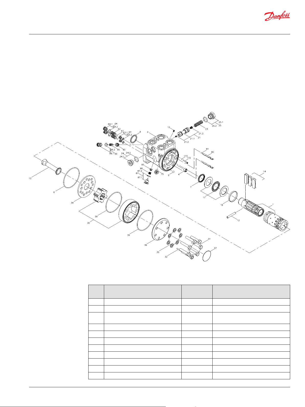
Exploded view, VSPP
VSPP exploded view
VSPP is only available as “Load Sensing dynamic, non-reaction” version.
The exploded view is universal. Some variants are without shock and suction valves.
Parts list, VSPP
Item Description
1 Spool/sleeve set 1 2 Housing 1 4 Threaded bushing (Screw below surface of
5 Ball Ø6.0 mm 1 6 O-ring Ø79.4 x Ø2.0 mm 1 7 Shaft seal 1 9 Dust seal ring 1 10 Orifice, LS 1 1 ± 0.1 N•m [8.9 ± 0.9 lbf•in]
12 Cross pin 1 13 Cardan shaft 1 14 Set of springs 1 -
©
Danfoss | November 2019 AX319758618681en-000101 | 5
housing)
Number per
unit
1 -
Tightening torque
Page 6

Service Manual
VSPP Steering unit
VSPP version overview
Item Description
16 Ring 1 17 Bearing assembly 1 21 Spool, priority valve with orifices 1 -
21.1 Spool 1 -
21.2 Orifice, PP 1 1 ± 0.1 N•m [8.9 ± 0.9 lbf•in]
21.3 Orifice, Dynamic 1 3.5 ± 0.5 N•m [31 ± 4.4 lbf•in]
23 Compression spring 1 24 Plug with O-ring 1 40 ± 10 N•m [354 ± 88 lbf•in]
24.1 Plug 1 -
24.2 O-ring Ø15.3 x Ø2.4 mm 1 25 Plug with O-ring 1 40 ± 10 N•m [354 ± 88 lbf•in]
25.1 Plug 1 -
25.2 O-ring Ø15.3 x Ø2.4 mm 1 30 Gearwheel set 1 31 Screw 6 30 ± 6 N•m [265 ± 52 lbf•in]
32 Pin bolt screw 1 30 ± 6 N•m [265 ± 52 lbf•in]
34 Distributor plate 1 35 Washer 7 36 End cover 1 37 Model/Code label 1 39 O-ring Ø79.4 x Ø2.0 mm 2 61 Ball Ø3/16” 2 62 Spring with thrust pad for shock valve 2 63 Valve seat for shock valve with O-ring 2 6 +0/-1 N•m [59 +0/- 8.9 lbf•in]
63.1 Valve seat for shock 2 -
63.2 O-ring Ø6 x Ø1,5 mm 2 64
64.1 Adjusting screw 2 -
64.2 O-ring Ø9 x Ø1,5 mm 2 75 Plug with O-ring 1 20 ± 5 N•m [177 ± 44 lbf•in]
80 Pin 2 81 Ball Ø3/16” 2 85 Valve cone, P-check 1 86 Compression spring 1 87 Screw with O-ring 1 20 ± 5 N•m [177 ± 44 lbf•in]
87.1 Screw 1 -
87.2 O-ring Ø9 x Ø1,5 mm 1 90 Valve seat for pilot relief 1 20 ± 3 N•m [177 ± 27 lbf•in]
95 Spring with cone for pilot relief valve 1 99
99.1 Adjusting screw 1 -
99.2 O-ring Ø9 x Ø2.0 mm 1 172 Pin bolt screw for LS check 1 1 ± 0.1 N•m [8.9 ± 0.9 lbf•in]
173 Ball Ø3,5 mm 1 -
Adjusting screw for shock valve
with O-ring
Adjusting screw for pilot relief valve
with O-ring
Number per
unit
2 -
1 -
Tightening torque
6 | © Danfoss | November 2019 AX319758618681en-000101
Page 7
90±1
ø46±0.5
120±2
2xø15±0.1
5±1
20±1
150±2
100±2
7x51.4°
ø64
7xø15+0.5/-0
1x45°
P301 644
Service Manual
VSPP Steering unit
VSPP version overview
Seal kit for VSPP
Required tools
Spare parts list Code number Item
Seal kit for VSPP 150N4038 6, 7, 9, 24.2, 25.2, 35, 39, 63.2, 64.2,
87.2, 99.2
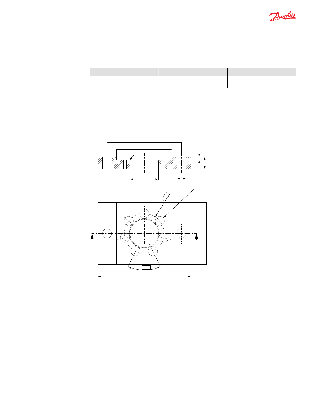
VSPP holding tool
Holding tool dimensions drawing
©
Danfoss | November 2019 AX319758618681en-000101 | 7
•
Material: Appropriate metal or hard plastic.
•
This tool is not available from Danfoss.
Page 8
0.5x45°
ø26±0.1
min ø40
min 35
100±5
P301 643
Service Manual
VSPP Steering unit
VSPP version overview
Assembly tool for dust seal
Assembly tool for dust seal
•
Material: Free cutting steel.
•
This tool is not available from Danfoss
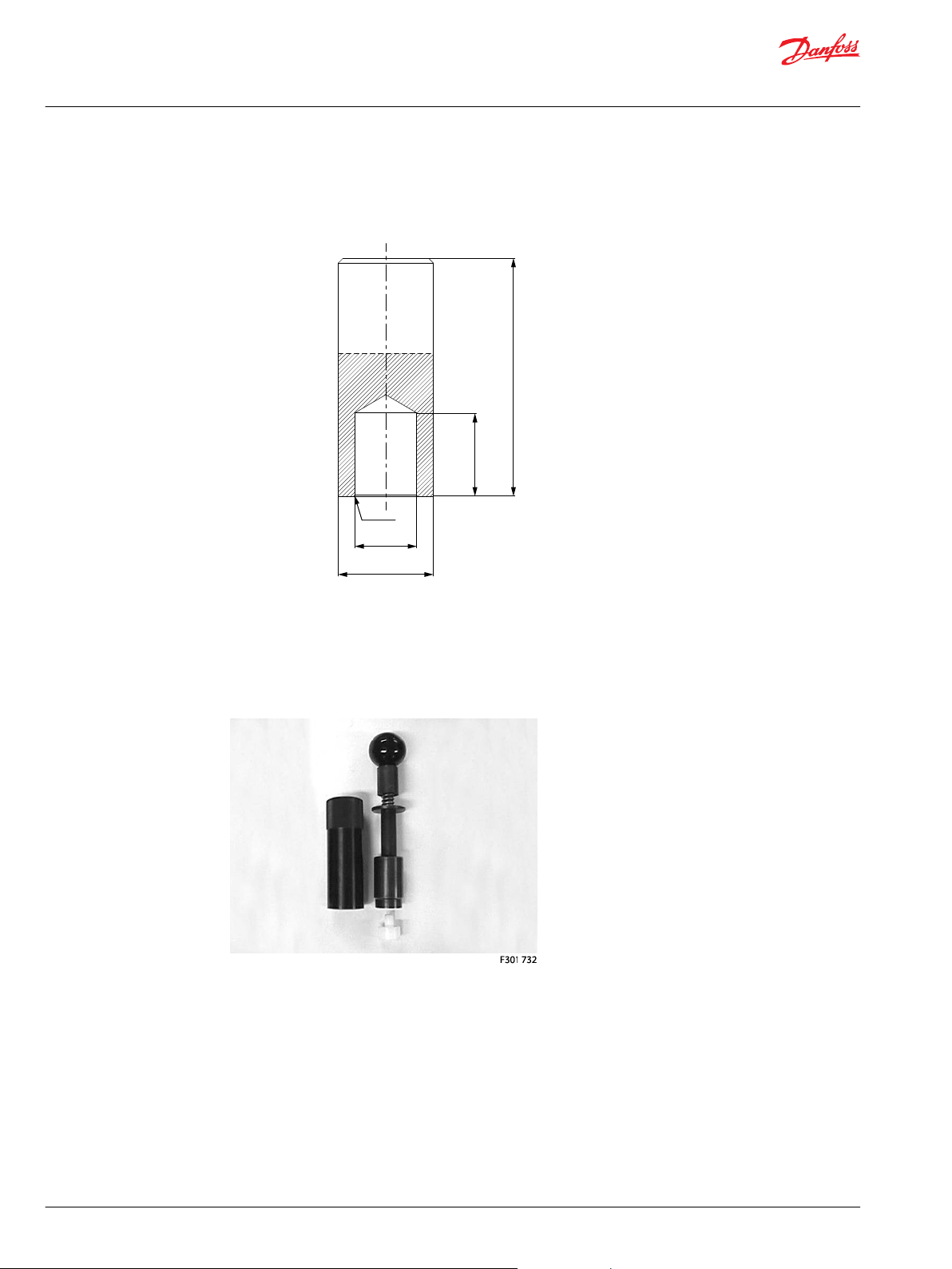
Assembly tool for shaft sea, O-ring / RotoGlyd type
Assembly tool for shaft seal, O-ring / Roto Glyd type
•
Code number: 11092408.
8 | © Danfoss | November 2019 AX319758618681en-000101
Page 9
Service Manual
VSPP Steering unit
VSPP version overview
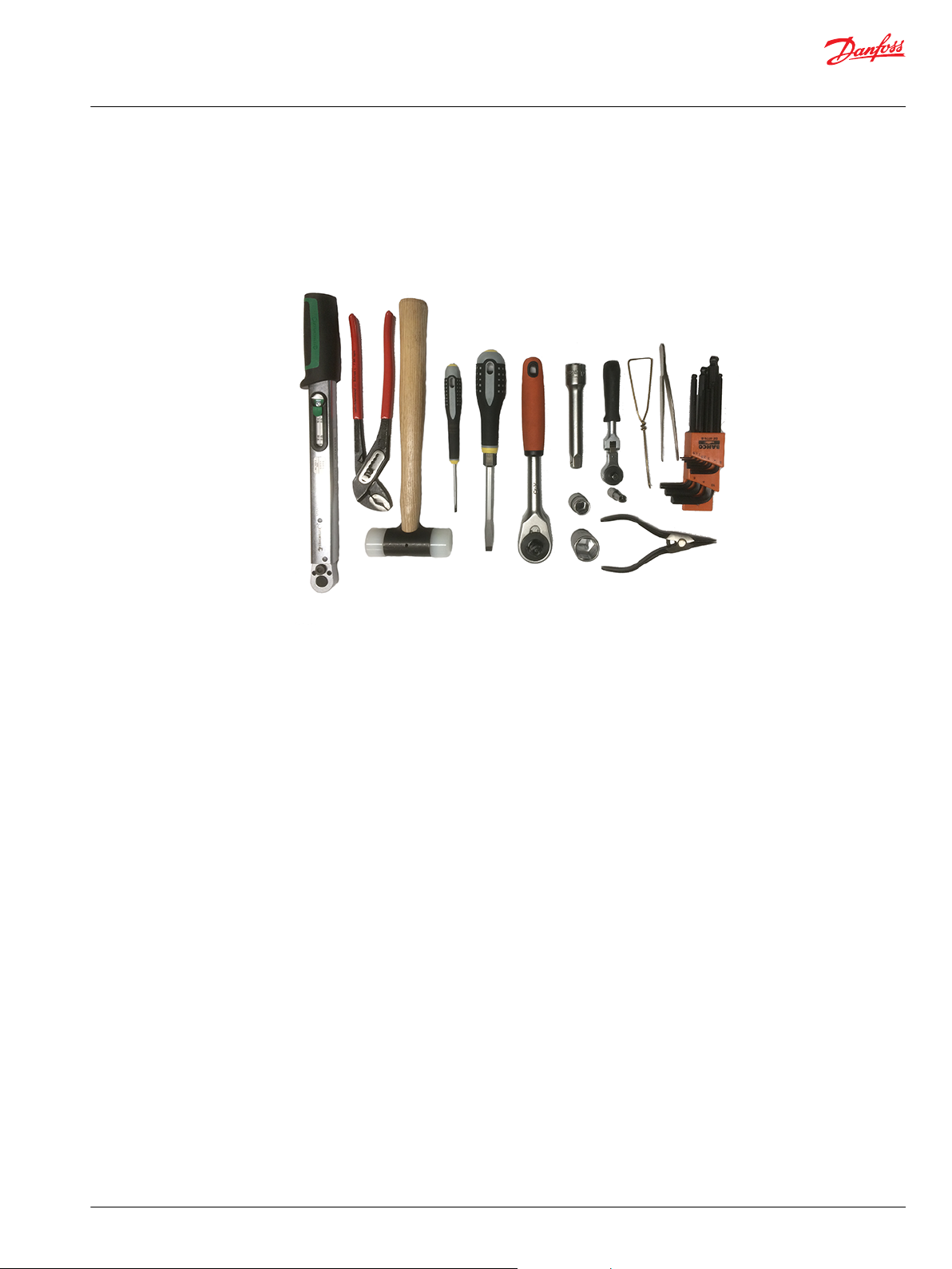
Additional tools needed
These tools are not available from Danfoss:
Additional tools needed
•
Torque wrench, 0-70 Nm
•
Socket spanner for external hexagon: 6, 13, and 22 mm
•
Hex keys for internal hexagon: 2, 2.75, 3, 5, 6, and 8 mm
•
Screwdrivers: 2 and 12 mm
•
Incide circlip pliers
•
Magnetic rod
•
Hook of max 2mm wire
•
Multigrip pliers
•
Plastic hammer
©
Danfoss | November 2019 AX319758618681en-000101 | 9
Page 10
Service Manual
VSPP Steering unit
VSPP disassembly
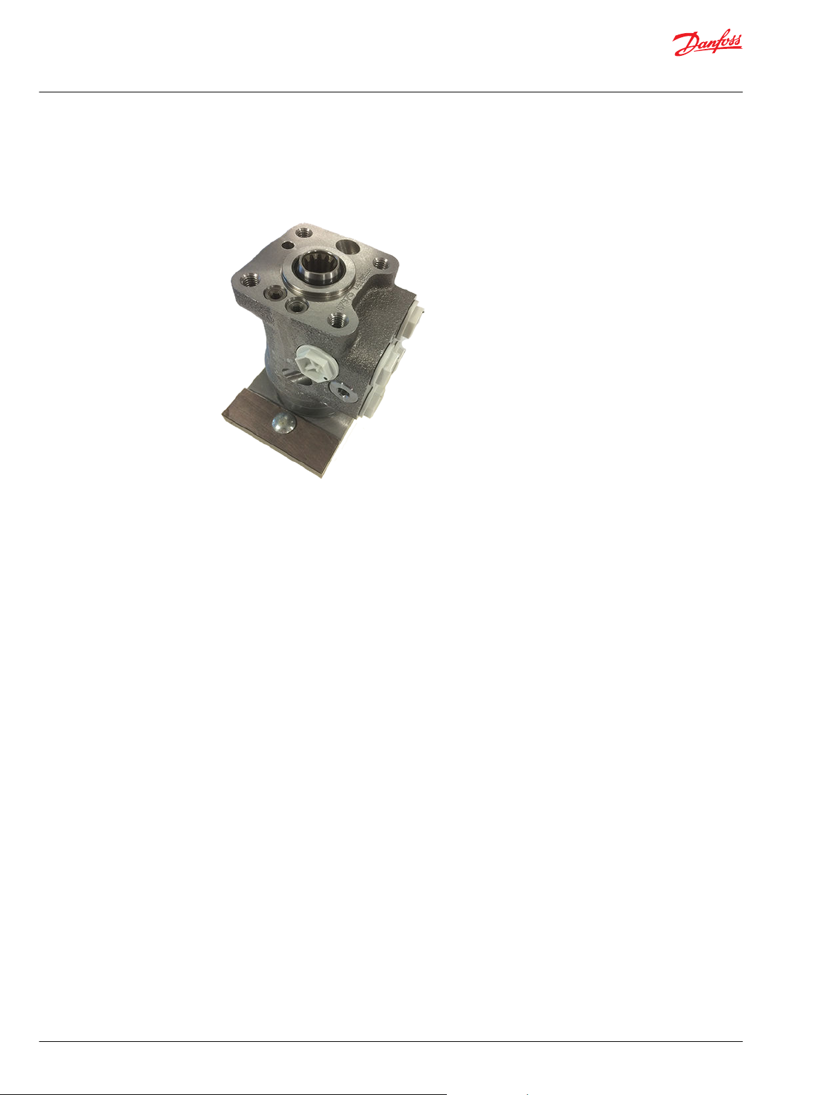
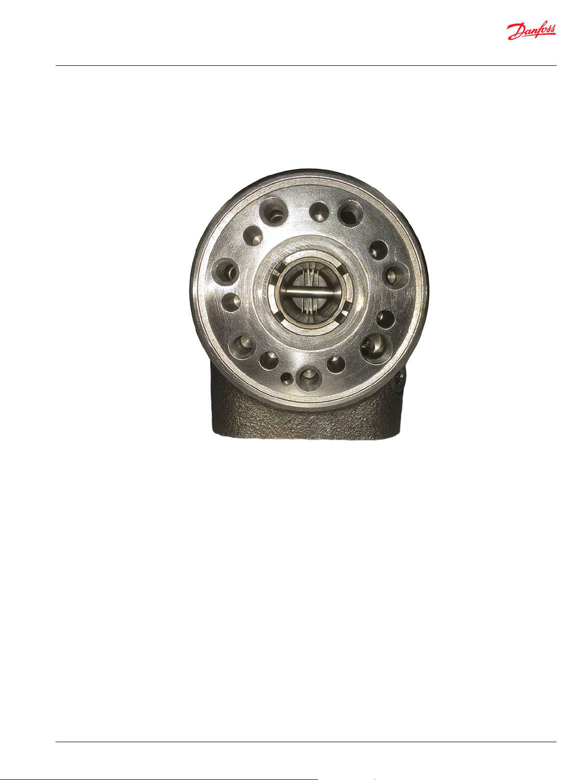
To disassemble VSPP Steering Unit, follow these steps.
Place the unit on the holding tool on the gear set end.
VSPP Steering Unit mounted on holding tool
10 | © Danfoss | November 2019 AX319758618681en-000101
Page 11
Service Manual
VSPP Steering unit
VSPP disassembly
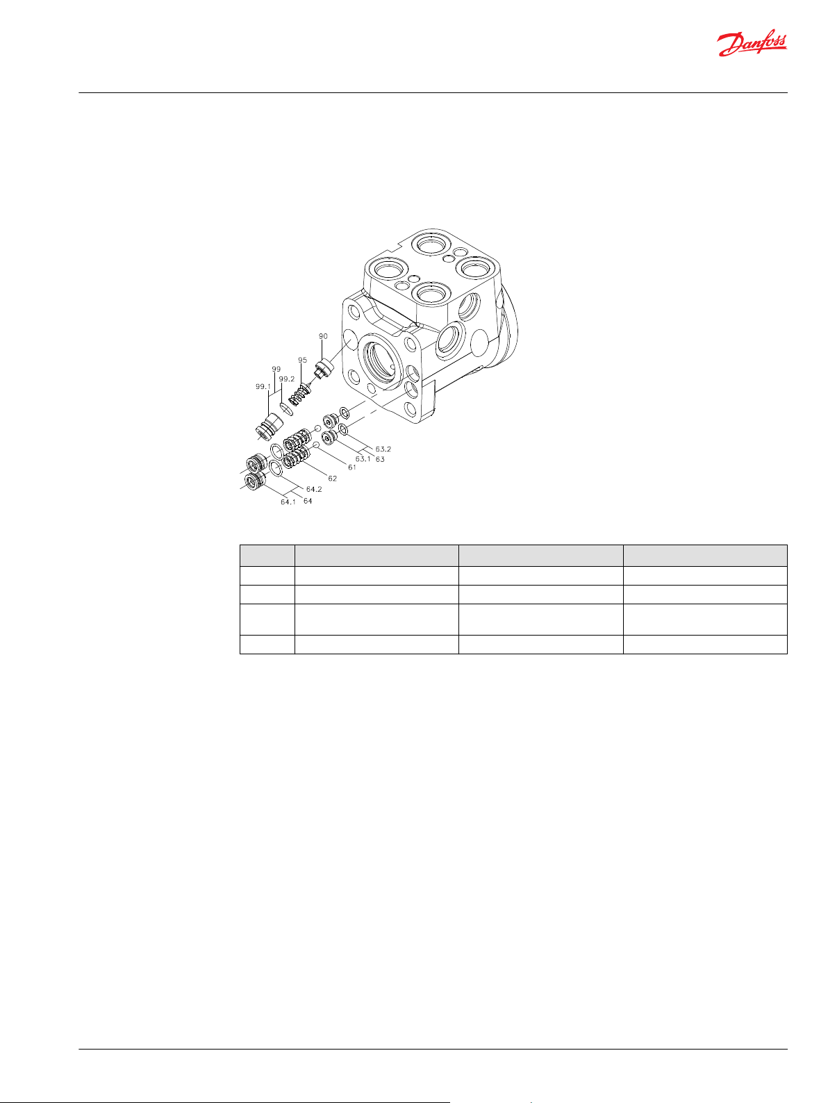
Remove shock and relief valves from housing
To remove shock and relief valve parts from housing, follow these steps.
VSPP shock and relief valve parts
Wrench size and torque
Item Description Wrench size Torque
64 Adjusting screw for shock valve 5 mm Hex key 63 Valve seat for shock valve 2.75 mm Hex key 6 +0/-1 N•m [59 +0/- 8.9 lbf•in]
99 Adjusting screw for pilot relief
valve
90 Valve seat for pilot relief valve 6 mm Socket spanner 20 ± 3 N•m [177 ± 27 lbf•in]
6 mm Hex key -
1. Screw off the adjusting screws (2x64) using a 5mm Hex key.
O-rings (2x64.2) are fitted to the adjusting screws.
2. Remove the springs with a thrust pad (2x62) using a 2mm flat head screwdriver.
3. Remove the balls (2x61) using a magnet rod.
4. Screw out the valve seat (2x63) using a 2.75mm Hex key.
O-rings (2x63.2) are fitted to the valve seats.
5. Screw out the adjusting screw (99) using a 6mm Hex key.
O-ring (99.2) is fitted to the adjusting screw.
6. Remove the spring with cone (95) using a 2mm flat head screwdriver.
If the cone is not following the spring, remove the cone by using a magnet rod.
7. Remove the valve seat (90) using a 6mm socket spanner.
©
Danfoss | November 2019 AX319758618681en-000101 | 11
Page 12

Service Manual
VSPP Steering unit
VSPP disassembly
Remove priority valve parts and P-check from housing
To remove priority valve parts and P-check valve parts from housing, follow these steps.
Replace the VSPP unit in the holding tool, so that it’s placed with the column surface on the fixture.
VSPP placed on column surface in the fixing tool
12 | © Danfoss | November 2019 AX319758618681en-000101
Page 13

Service Manual
VSPP Steering unit
VSPP disassembly
Priority valve parts and P-check details
VSPP priority valve and P-check parts
Wrench size and torque
Item Description Wrench size Torque
25 Plug with O-ring 22 mm Socket spanner 40 ± 10 N•m [354 ± 88 lbf•in]
21.2 Orifice, PP 2 mm Hex key 1 ± 0.1 N•m [8.9 ± 0.9 lbf•in]
21.3 Orifice, Dynamic 3 mm Hex key 3.5 ± 0.5 N•m [31 ± 4.4 lbf•in]
24 Plug with O-ring 8 mm Hex key 40 ± 10 N•m [354 ± 88 lbf•in]
10 Orifice, LS 2 mm Hex key 1 ± 0.1 N•m [8.9 ± 0.9 lbf•in]
87 Screw with O-ring 6 mm Hex key 20 ± 5 N•m [177 ± 44 lbf•in]
1. Screw off the plug (25) using a 22 mm socket spanner.
O-ring (25.2) is fitted to the plug
2. Remove the spring (23) using a hook.
3. Remove the spool (21) using and incide circlip pliers.
Orifices (21.2) and (21.3) are fitted to the spool
a) Before removing orifices (21.2) and (21.3), fix the spool in a vice with aluminum jaws.
b) Screw out PP orifice (21.2) using a 2mm Hex key.
c) Screw out dynamic orifice (21.3) using a 3mm Hex key.
4. Screw off the plug (24) using an 8mm Hex key.
O-ring (24.2) is fitted to the plug.
5. Screw off the LS orifice (10) from priority spool bore of housing (2) using a 2mm Hex key.
©
Danfoss | November 2019 AX319758618681en-000101 | 13
Page 14

Service Manual
VSPP Steering unit
VSPP disassembly
6. Screw off the screw (87) using a 6mm Hex key.
O-ring (87.2) is fitted to the screw.
7. Remove the spring (86).
8. Remove the valve cone (85)
Do not remove plug (75). This is a pure blinding plug.
O-ring is not available for this plug in the seal kit.
14 | © Danfoss | November 2019 AX319758618681en-000101
Page 15

Service Manual
VSPP Steering unit
VSPP disassembly
Remove end cover, gear set, cardan shaft, distributor plate, O-rings and valves from gear set end of housing
To remove end cover, gear set, cardan shaft, distributor plate, suction-, LS-check- and emergency steer
valves from housing, follow these steps.
End cover, gear set, cardan shaft, distributor plate, O-rings, and valves parts
Wrench size and torque
Item Description Wrench size Torque
31 Screw 13 mm socket spanner 30 ± 6 N•m [265 ± 52 lbf•in]
32 Pin bolt screw 13 mm socket spanner 30 ± 6 N•m [265 ± 52 lbf•in]
4 Threaded bushing 12 mm screw driver -
172 Pin bolt screw for LS check 2 mm Hex key 1 ± 0.1 N•m [8.9 ± 0.9 lbf•in]
1. Screw off the six screws (31) using a 13mm socket spanner.
2. Screw off the pin bolt screw (32) using a 13mm socket spanner.
3. Remove the washers (35).
4. Remove the end cover (36) by sliding sideward.
5. Lift the gear wheel set (30) off the unit.
Remove the two O-rings (39) from the gear rim.
6. Remove the cardan shaft (13).
7. Remove the distributor plate (34).
8. Remove the O-ring (6) from housing.
9. Screw out the Pin bolt screw (172) using a 2mm Hex key.
10. Drag out the suction pins (80) using a hook.
It may be needed to line up the suction pin in the thread bore with a 2mm screw driver before it will
be possible to insert the hook into the cross hole of the suction pins.
11. Screw out threaded bushing (4) using a 12mm screw driver.
©
Danfoss | November 2019 AX319758618681en-000101 | 15
Page 16
Service Manual
VSPP Steering unit
VSPP disassembly
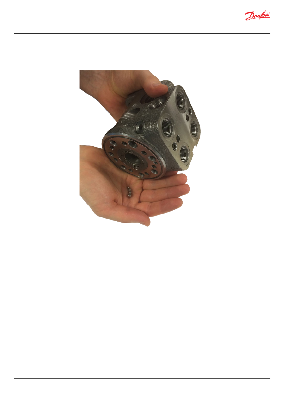
12. Lift off the VSPP housing from holding tool and let balls (5), (2x81), and (173) fall out.
Hold in hand to remove balls from gear set end
16 | © Danfoss | November 2019 AX319758618681en-000101
Page 17
Service Manual
VSPP Steering unit
VSPP disassembly
Remove spool/sleeve set from housing
1. Place the VSPP housing on the work pbench on the port face.
VSPP placed on port face on work bench
Determine if cross pin (12) in spool/sleeve set (1) is parallel to port face. If not, insert cardan shaft (13),
2.
and rotate spool/sleeve set (1) to position cross pin (12) correctly.
This is needed to make sure that cross pin (12) cannot fall into ring channels in housing (2) when
pressing out the spool/sleeve set.
3. Press out the spool/sleeve set (1) from housing (2). Cross pin (12), ring (16), set of spinrgs (14), and
bearing assembly (17) will follow the spool/sleeve set.
4. Take the bearing races and needle bearing (17) from the spool/sleeve set (1).
The outer bearing (17) race can sometimes "stick" in the housing. Therefore check that it has come
out.
©
Danfoss | November 2019 AX319758618681en-000101 | 17
Page 18
Service Manual
VSPP Steering unit
VSPP disassembly
Disassemble spool/sleeve set and remove dust seal and shaft from housing
1. Press out the cross pin (12).
2. Remove the ring (16).
3. Carefully press out the spool of the sleeve (1).
4. Press the set of neutral springs (14) out of the slot of the spool.
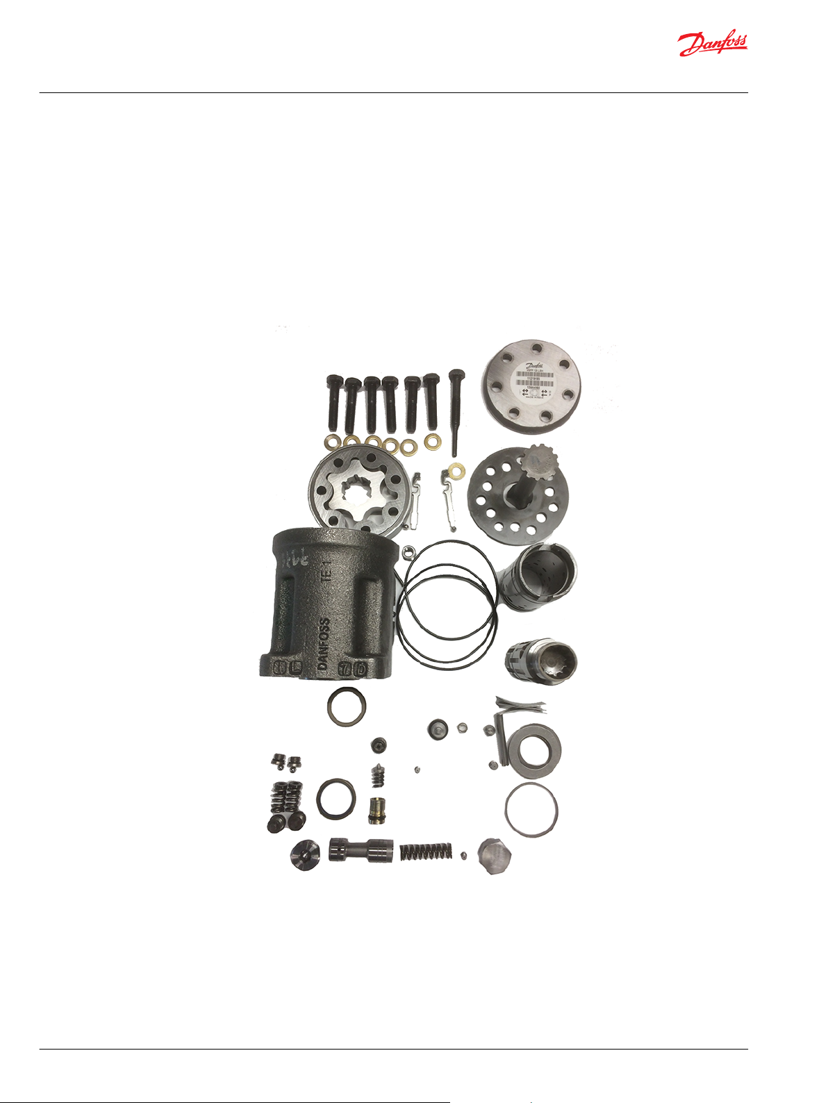
5. Remove the dust seal (9), and the shaft seal (7), carefully with a 2mm screw driver.
The VSPP steering unit is now completely dismantled.
Disassembled VSPP Steering unit
18 | © Danfoss | November 2019 AX319758618681en-000101
Page 19

Service Manual
VSPP Steering unit
VSPP maintenance
Cleaning
Inspection and replacement
Clean all parts carefully in Shellsol K or similar cleaning fluid.
Replace all seals and washers.
Place new O-rings from seal kit on plugs (24.1, 25.1, 64.1, 87.1, 99.1) and on seats (63.1).
Check all parts carefully and make any replacements as necessary.
©
Danfoss | November 2019 AX319758618681en-000101 | 19
Page 20
Service Manual
VSPP Steering unit
VSPP assembly
Assemble spool/sleeve set
To assemble spool/sleeve set with springs, cross pin, and ring, folow these steps.
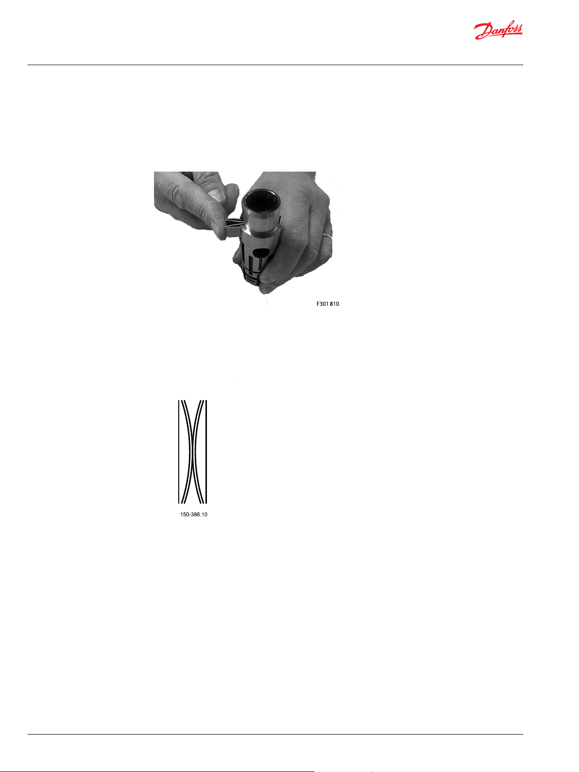
1. Place the curved springs between the flat ones and press them into place.
Press springs into place
Configuration of spring set (14):
There can be different numbers of curved springs, depending on configuration of spring set.
There can be 2, 4, or 6 curved springs.
Spring configuration
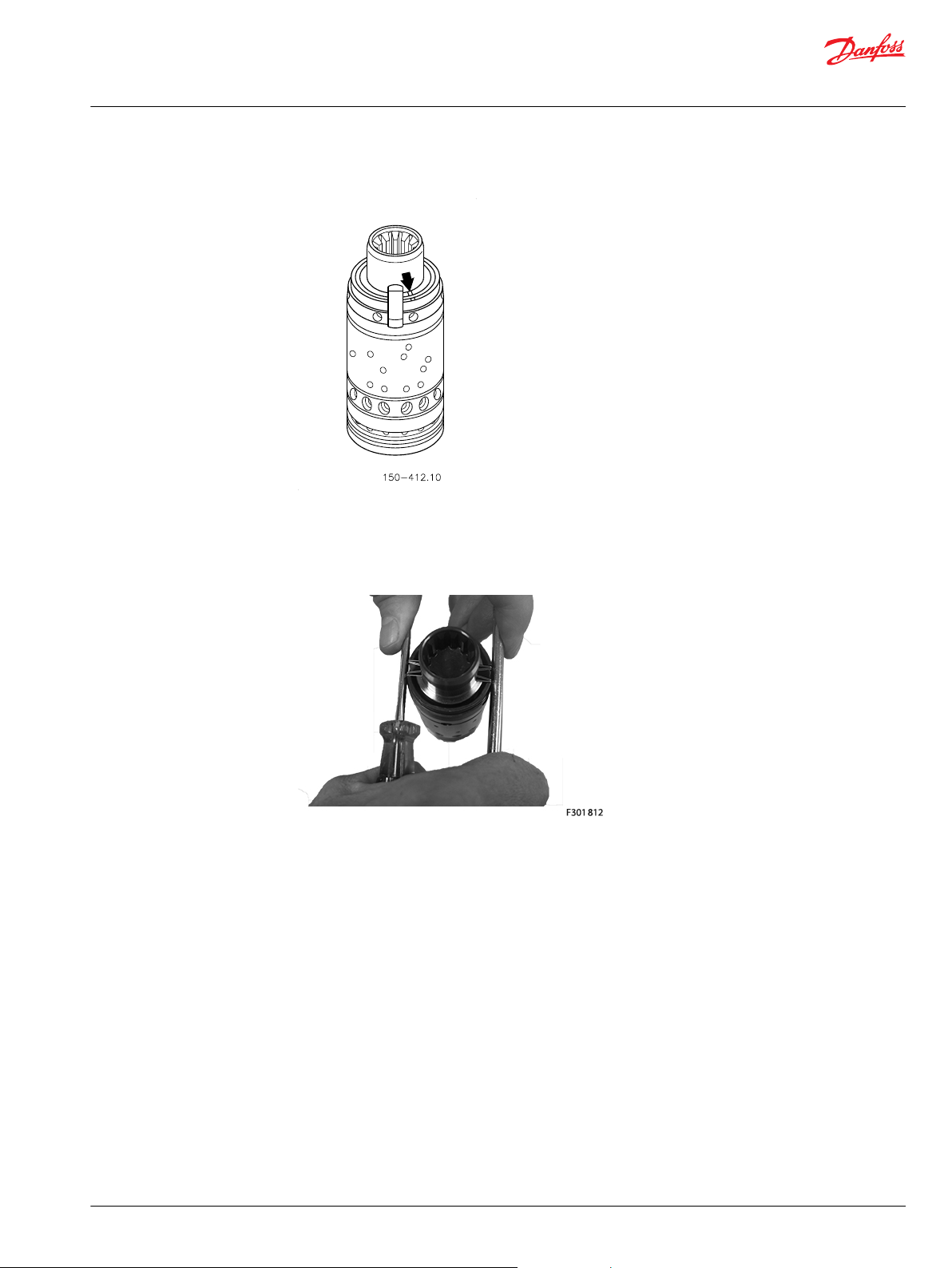
Some spool and sleeve sets for VSPP must be positioned correctly, relative to each other. Small marks
are present of both the spool and sleeve, close to one of the slots for the spring set.
Most spool and sleeve sets for VSPP have no marks, so those can be positioned relative to each other,
in either of the 2 positions possible.
20 | © Danfoss | November 2019 AX319758618681en-000101
Page 21
Service Manual
VSPP Steering unit
VSPP assembly
Marking on spool and sleeve
2. Guide the spool into the sleeve (1).
Make sure the neutral springs (14) are placed into the slot.
3. Line up the spring set (14).
Aligning the spring set
4. Guide the ring (16) down over the sleeve.
The ring sould be able to move freely of the springs.
5. Fit the cross pin (12) into the spool/sleeve set.
©
Danfoss | November 2019 AX319758618681en-000101 | 21
Page 22
Service Manual
VSPP Steering unit
VSPP assembly
6. Fit bearing races and needle bearing (17) as shown on the drawing below.
Standard bearing assembly pattern
Assembly pattern for standard bearing:
1. Outer bearing race
2. Needle bearing
3. Inner bearing race
4. Spool
5. Sleeve
The inside chamfer on the inner bearing race must face the chest of the inner spool.
22 | © Danfoss | November 2019 AX319758618681en-000101
Page 23
Service Manual
VSPP Steering unit
VSPP assembly
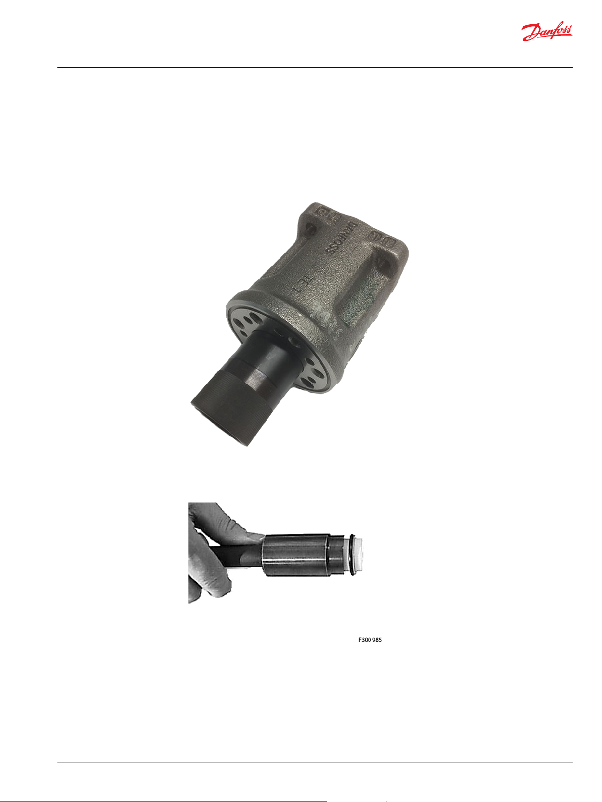
Assemble shaft seal and spool/sleeve set to housing
To assemble shaft seal and spool/sleeve set with springs, cross pin, ring and bearing assembly to the
housing, follow these steps.
1. Place the steering unit housing with the port face down on the work bench. Guide the outer part of
the assembly tool for shaft seal into the bore of housing (2) for the spool/sleeve set (1).
VSPP with guide for shaft seal.
2. Grease the new shaft seal (Roto Glyd. 7) with hydraulic oil and place them on the tool.
Ensure that the Roto Glyd seal is placed on the insertion tool as per the photograph.
Place the Roto Glyd seal on the insertion tool
©
Danfoss | November 2019 AX319758618681en-000101 | 23
Page 24
Service Manual
VSPP Steering unit
VSPP assembly
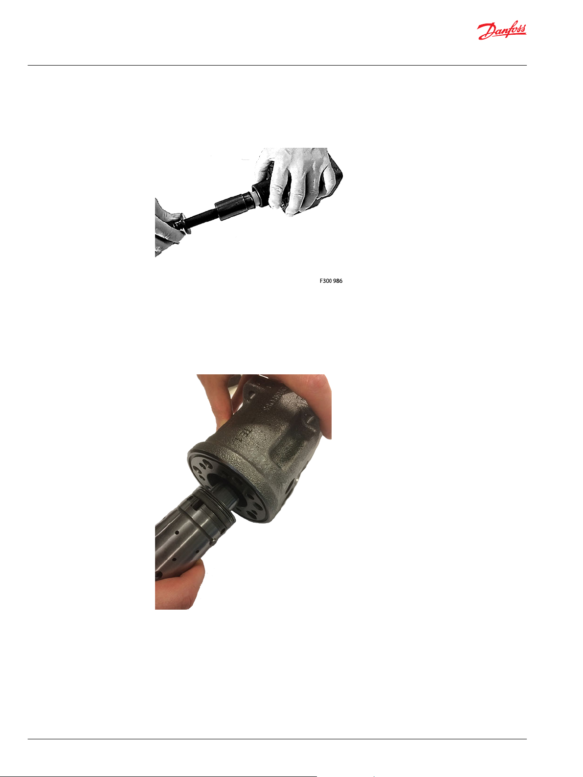
3. Hold the outer part of the assembly tool in the bottom of the steering unit housing and guide the
inner part of the tool right to the bottom.
Guid the inner part of the tool to the bottom
4. Press and turn the shaft seal (5) into position in the housing.
5. Draw the inner and outer parts of the assembly tool out of the steering unit bore, leaving the guide
from the inner part of the bore
6. Guide the spool and sleeve into the bore with a light turning movement.
Fit the spool set holding the cross pin (11) horizontally.
VSPP with spool set
24 | © Danfoss | November 2019 AX319758618681en-000101
Page 25
Service Manual
VSPP Steering unit
VSPP assembly
7. Install the shaft seal.
The spool set will push out the assembly tool guide.
©
Danfoss | November 2019 AX319758618681en-000101 | 25
Page 26

Service Manual
VSPP Steering unit
VSPP assembly
Assemble valve parts, O-rings, distributor plate, cardan shaft, gear set, and end cover to gear set end of housing
To assemble below parts to gear set end of housing, follow these steps.
Ensure that the VSPP unit is placed in the holding tool, with the column surface on the fixture.
VSPP correctly placed in holding tool for assembly
VSPP exploded view drawing - gear set end
Item Description Wrench size Torque
4 Threaded bushing 12 mm screw driver Screw below surface of housing
172 Pin bolt screw for LS check 2 mm Hex key 1 ± 0.1 N•m [8.9 ± 0.9 lbf•in]
31 Screw 13 mm socket spanner 30 ± 6 N•m [265 ± 52 lbf•in]
32 Pin bolt screw 13 mm socket spanner 30 ± 6 N•m [265 ± 52 lbf•in]
1. Place balls as illustrated in the drawing:
a) Place ball (1x 5) Ø6mm for emergency steering.
b) Place ball (2x 81) Ø5/16” /Ø4,8 mm for suction valves.
c) Place ball (1x 173) Ø3,5 mm for LS-check function.
26 | © Danfoss | November 2019 AX319758618681en-000101
Page 27

Service Manual
VSPP Steering unit
VSPP assembly
Ball placement drawing
2. Screw in threaded bushing (4) using a 12mm screw driver.
Screw below surface of housing.
3. Screw in pin bolt screw for LS check using a 2mm Hex key.
Tightening torque: 1 ± 0.1 N•m [8.9 ± 0.9 lbf•in]
4. Place pins (2x80) on top of balls (81).
For viewing below items, see Exploded view, VSPP on page 5.
5. Insert the O-ring (6) in the groove of the housing.
6. Place the distributor plate (34) so that the outer holes match the tread holes in the housing.
7. Guide the cardan shaft (13) down into the bore so that the slot is parallel with the cross pin (12).
8. Place the two O-rings (39) in the two grooves in the gear rim.
9. Fit the gearwheel and rim (30) on the cardan shaft (13).
Place the gear wheel side with all the deeper splines facing downdwards. Only this side will fit on the
cardan shaft due to all gear sets used in VSPP hasve timing securing:
splines of gear wheel and cardan shaft can only be assembled with correct timing.
Line up the gear rim holes to match the thread holes of the housing.
10. Place the end cover (36) into position.
Ensure that the bar codes and writing are parallel with the port face.
11. Fit off the pin bolt screw (32) with washer (35) and place in the position as shown in the detail
drawing.
12. Fit off the six screws (31) with washers (35), and insert through holes in end cover.
13. Cross tighten the 7 screws (31 + 32) using a 13mm socket spanner.
Tightening torque: 30 ± 6 N•m [265 ± 52 lbf•in]
©
Danfoss | November 2019 AX319758618681en-000101 | 27
Page 28

Service Manual
VSPP Steering unit
VSPP assembly
Assemble priority valve parts and P-check to housing
VSPP priority valve and P-check parts
Wrench size and torque
Item Description Wrench size Torque
25 Plug with O-ring 22 mm Socket spanner 40 ± 10 N•m [354 ± 88 lbf•in]
21.2 Orifice, PP 2 mm Hex key 1 ± 0.1 N•m [8.9 ± 0.9 lbf•in]
21.3 Orifice, Dynamic 3 mm Hex key 3.5 ± 0.5 N•m [31 ± 4.4 lbf•in]
24 Plug with O-ring 8 mm Hex key 40 ± 10 N•m [354 ± 88 lbf•in]
10 Orifice, LS 2 mm Hex key 1 ± 0.1 N•m [8.9 ± 0.9 lbf•in]
87 Screw with O-ring 6 mm Hex key 20 ± 5 N•m [177 ± 44 lbf•in]
1. Assemble the spool (21) with orifices (21.2) and (21.3) to the spool (21.1).
a) Before assembling orifices (21.2 and 21.3) to the spool: fix the spool in a vice with aluminum jaws.
b) Screw in PP orifice (21.2) using a 2mm Hex key.
Tightening torque: 1 ± 0.1 N•m [8.9 ± 0.9 lbf•in]
c) Screw in dynamic orifice (21.3) using a 3mm Hex key.
Tightening torque: 3.5 ± 0.5 N•m [31 ± 4.4 lbf•in]
2. Screw in the LS orifice (10) into the thread hole in the priority spool bore of housing (2) using a 2mm
Hex key.
Tightening torque: 1 ± 0.1 N•m [8.9 ± 0.9 lbf•in]
3. Screw in the plug (24) using an 8mm Hex key.
O-ring (24.2) is fitted to the plug.
Tightening torque: 40 ± 10 N•m [354 ± 88 lbf•in]
4. Insert the priority valve spool with orifices (21).
5. Insert the spring (23).
28 | © Danfoss | November 2019 AX319758618681en-000101
Page 29

Service Manual
VSPP Steering unit
VSPP assembly
6. Screw in the plug (25) using a 22mm socket spanner.
O-ring (25.2) is fitted to the plug.
Tightening torque: 40 ± 10 N•m [354 ± 88 lbf•in]
7. Insert the cone (85).
8. Insert the spring (86).
9. Screw in the screw (87) using an 8mm Hex key.
O-ring (87.2) is fitted to the screw.
Tightening torque: 20 ± 5 N•m [177 ± 44 lbf•in]
Assemble shock and relief valves, and dust seal, to housing
To assemble shock and relief valve parts to the column end of the housing, follow these steps.
Place the unit on the holding tool on the gear set end.
VSPP placed on mounting tool - gear set end
©
Danfoss | November 2019 AX319758618681en-000101 | 29
Page 30

Service Manual
VSPP Steering unit
VSPP assembly
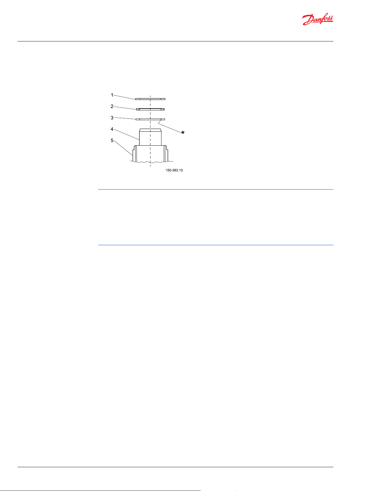
Assembly details for shock and relief valves, and dust seal
VSPP shock and relief valve parts
Wrench size and torque
Item Description Wrench size Torque
64 Adjusting screw for shock valve 5 mm Hex key 63 Valve seat for shock 2.75 mm Hex key 6 +0/-1 N•m [59 +0/- 8.9 lbf•in]
99 Adjusting screw for pilot relief
valve
90 Valve seat for pilot relief 6 mm Socket spanner 20 ± 3 N•m [177 ± 27 lbf•in]
6 mm Hex key -
1. Screw in the valve seat (90) using a 6mm socket spanner.
Tightening torque: 20 ± 3 N•m [177 ± 27 lbf•in]
2. Insert the spring with cone (95).
3. Screw in the adjusting screw (99) using a 6mm Hex key.
Screw in until head of screw is 5-8mm below level of housing surface, measured on the "less deep
side" of the slanted bore.
Relief valve shall be adjusted in hydraulic test, see Testing of VSPP on page 32.
4. Screw in the valve seat (63) using a 2.75mm Hex key.
O-rings (2x63.2) are fitted to the valve seats.
Tightening torque: 6 +0/-1 N•m [59 +0/- 8.9 lbf•in]
5. Insert the balls (2x61).
6. Insert the springs with thrust pad (2x62).
7. Screw in the adjusting screws (2x64) using a 5mm Hex key.
O-rings (64.2) are fitted to the adjusting screws.
Screw in until head of screws are just below level of housing surface.
Relief valve shall be adjusted in hydraulic test, see Testing of VSPP on page 32.
8. Place the dust seal ring (9) in the housing.
Fit the dust seal ring using special tool dust seal assembly (see Required tools on page 7), and a plastic
hammer.
9. Make test and valve settings according to description in the following pages.
30 | © Danfoss | November 2019 AX319758618681en-000101
Page 31

Service Manual
VSPP Steering unit
VSPP assembly
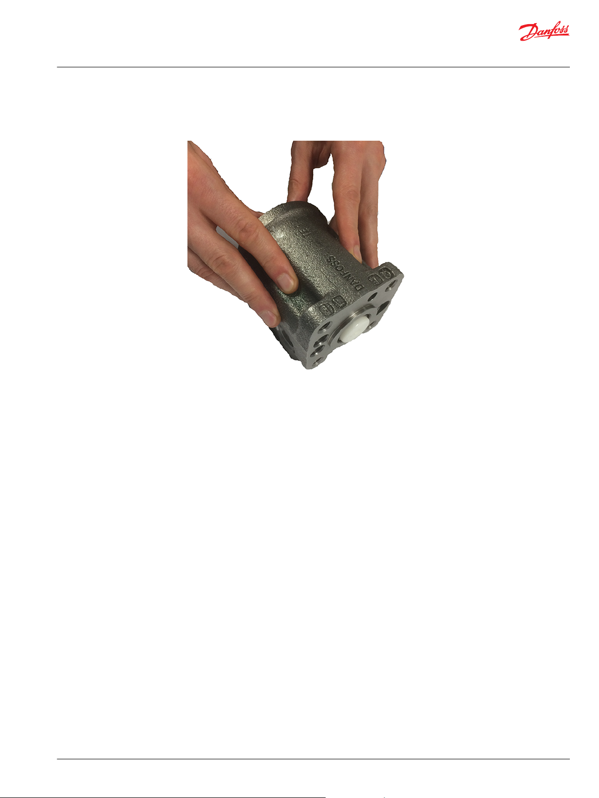
10. Screw in plastic plugs to the connections ports to keep the ports clean during storage and
transportation.
VSPP with plastic plugs in ports
©
Danfoss | November 2019 AX319758618681en-000101 | 31
Page 32
Service Manual
VSPP Steering unit
Testing of VSPP
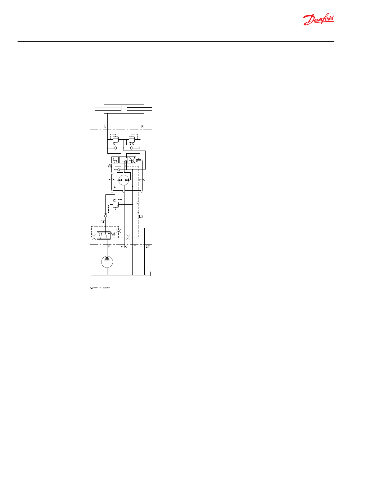
This section describes minimum tests needed, when the VSPP steering valve has been disassembled and
reassembled.
Example of system setup: VSPP steering unit with supply from gear pump.
VSPP in system
Set-up for testing
Use universal hydraulic work bench with pump capacity:
•
3 l/min and 270 bar for shock valve testing
•
25 l/min and up to 190 bar pressure for relief valve setting and steering test
The hydraulic oil must be with a viscosity of 21 cSt. at 50° and with max. degree of contamination
according to ISO 4406: 21 / 19 / 16.
32 | © Danfoss | November 2019 AX319758618681en-000101
Page 33

Service Manual
VSPP Steering unit
Testing of VSPP
Shock valves
Steering tests
Description for setting of shock valves:
1. Connect T and EF port of VSPP to tank of pump station.
2. Plug P-port of VSPP.
3. Connect P port from pump supply to one servo port at a time (L and R), plug opposite servo port.
4. Connect pressure gauge to the servo port connected to P of pump station and to T of pump station.
5. The shock valves are to be set at an oil flow of 3 l/min applied to one of the servo ports L and R at a
time.
6. The shock valve (item 64, see Exploded view, VSPP on page 5) is set according to specification:
Pressure (R-T/L-T), bar, for the code in question.
T pressure should not exceed ~5 bar. Max. allowed T pressure is 30 bar.
Pump supply circuit must be adjusted not to exceed 270 bar P-T at shock valve setting.
Description for system setup for steering tests:
1. Connect double rod cylinder to L and R ports of VSPP.
2. Connect T and EF port of VSPP to tank of pump station.
3. Connect P port of VSPP to P port from pump.
4. Connect pressure gauges to all ports of VSPP.
5. Connect steering column and steering wheel to VSPP surface for column.
Column must allow access to the adjusting screw for pilot relief valve by cut-out in the foot plate.
Start up test
Pilot relief valve test
T pressure should not exceed ~5 bar. Max allowed T pressure is 30 bar.
Pump supply circuit must be adjusted not to exceed 190 bar P-T at steering test.
During the testing, no disturbing vibrations, noise, or other irregularities must occur.
1. Start the pump.
The pump flow is adjusted to approximately 25 l/min and pump pressure control must be set to
approximately 70 bar.
2. Let the supplied oil flow through the steering unit for a few minutes.
3. Operate the steering wheel to move the steering cylinder from end stroke to end stroke for at least 5
cycles.
Make sure pressure P-T, 70 bar can be achieved, when steering against end stroke.
If this is not possible, the adjusting screw of the pilot relief valve (item 99, see Exploded view, VSPP on
page 5) must be turned clockwise until P-T, 70 bar is achievable.
1. Adjust the pump flow to approximately 25 l/min and pressure to maximum 190 bar.
2. The steering wheel is actuated until the steering cylinder reaches one of its end strokes and the
steering wheel is actuated in this cylinder position with steering torque 25 ±5 Nm.
3. The pilot relief valve (item 99, see Exploded view, VSPP on page 5) is set according to specification:
Maximum steering pressure (P-T), bar, for the code in question.
The setting pressure is the pressure on the P-port minus the T-port of VSPP.
©
Danfoss | November 2019 AX319758618681en-000101 | 33
Page 34

Service Manual
VSPP Steering unit
Testing of VSPP
Neutral positioning test
Check for external leakage
1. After adjusting the pilot relief valve, the steering wheel must be able to go to neutral position by itself
no later than ~1 second after the activation of the steering wheel has been stopped.
2. The steering unit is in neutral position when the pressure drop (P-T) is no higher than 18 bar.
1. After testing of the former items, the port connections are removed.
2. P, EF, L, and R ports are to be plugged with steel plugs.
3. Oil pressure of 20 bar is supplied to the T-front port for approximately 3 minutes:
No leakage must be found in any assemblies.
34 | © Danfoss | November 2019 AX319758618681en-000101
Page 35
Service Manual
VSPP Steering unit
Tightening torques for connections
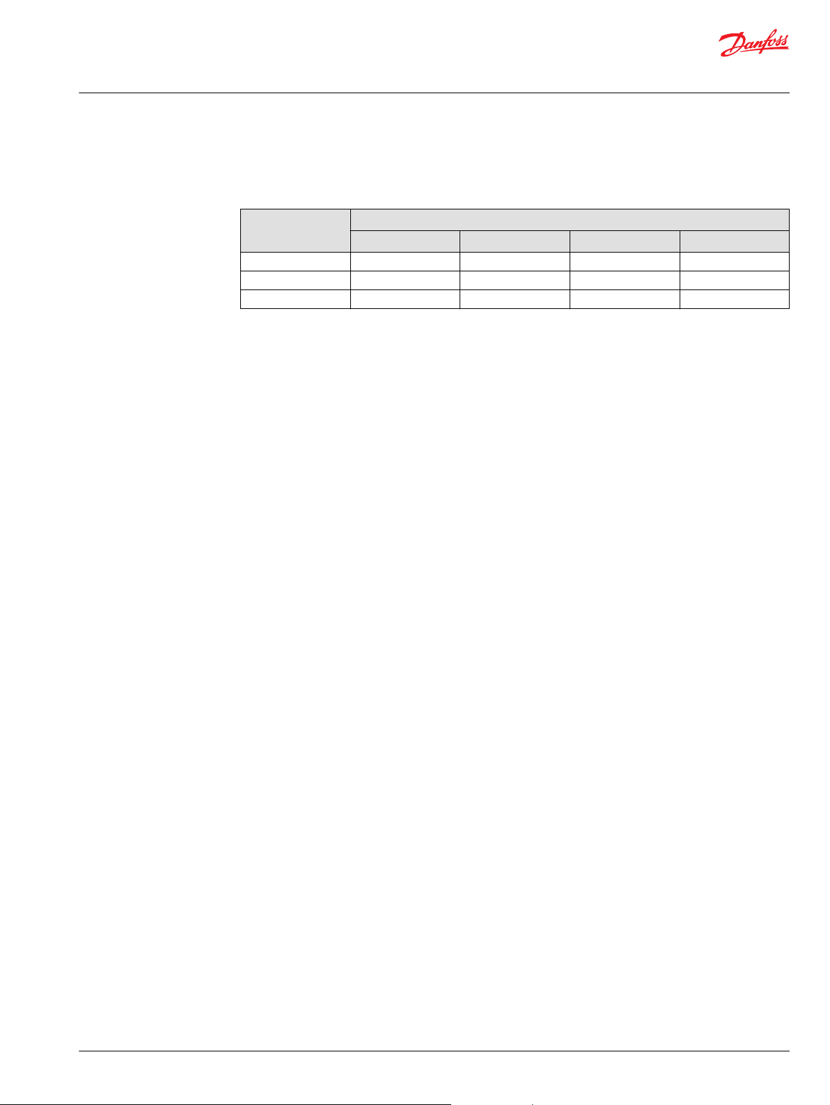
Tightening torques for connections
Tightening torques for connections on VSPP
Connections Recommended tightening torque N•m [lbf•in]
G 1⁄2 100 [885] 55 [486] 80 [708] 3⁄4-16 UNF - - - 60 [531]
M18 • 1.5 80 [708] 55 [486] 70 [619] 50 [442]
With cutting edge With copper washer With alum. washer O-ring
©
Danfoss | November 2019 AX319758618681en-000101 | 35
Page 36

Danfoss
Power Solutions GmbH & Co. OHG
Krokamp 35
D-24539 Neumünster, Germany
Phone: +49 4321 871 0
Danfoss
Power Solutions ApS
Nordborgvej 81
DK-6430 Nordborg, Denmark
Phone: +45 7488 2222
Danfoss
Power Solutions (US) Company
2800 East 13th Street
Ames, IA 50010, USA
Phone: +1 515 239 6000
Danfoss
Power Solutions Trading
(Shanghai) Co., Ltd.
Building #22, No. 1000 Jin Hai Rd
Jin Qiao, Pudong New District
Shanghai, China 201206
Phone: +86 21 2080 6201
Products we offer:
Hydro-Gear
www.hydro-gear.com
Daikin-Sauer-Danfoss
www.daikin-sauer-danfoss.com
DCV directional control
•
valves
Electric converters
•
Electric machines
•
Electric motors
•
Gear motors
•
Gear pumps
•
Hydrostatic motors
•
Hydrostatic pumps
•
Orbital motors
•
PLUS+1® controllers
•
PLUS+1® displays
•
PLUS+1® joysticks and
•
pedals
PLUS+1® operator
•
interfaces
PLUS+1® sensors
•
PLUS+1® software
•
PLUS+1® software services,
•
support and training
Position controls and
•
sensors
PVG proportional valves
•
Steering components and
•
systems
Telematics
•
Danfoss Power Solutions is a global manufacturer and supplier of high-quality hydraulic and
electric components. We specialize in providing state-of-the-art technology and solutions
that excel in the harsh operating conditions of the mobile off-highway market as well as the
marine sector. Building on our extensive applications expertise, we work closely with you to
ensure exceptional performance for a broad range of applications. We help you and other
customers around the world speed up system development, reduce costs and bring vehicles
and vessels to market faster.
Danfoss Power Solutions – your strongest partner in mobile hydraulics and mobile
electrification.
Go to www.danfoss.com for further product information.
We offer you expert worldwide support for ensuring the best possible solutions for
outstanding performance. And with an extensive network of Global Service Partners, we also
provide you with comprehensive global service for all of our components.
Local address:
Danfoss can accept no responsibility for possible errors in catalogues, brochures and other printed material. Danfoss reserves the right to alter its products without notice. This also applies to products
already on order provided that such alterations can be made without subsequent changes being necessary in specifications already agreed.
All trademarks in this material are property of the respective companies. Danfoss and the Danfoss logotype are trademarks of Danfoss A/S. All rights reserved.
©
Danfoss | November 2019 AX319758618681en-000101
 Loading...