How it Works
Log In / Sign Up
Buy Points
How it Works
FAQ
Contact Us
Questions and Suggestions
Users
Danfoss
Loading...
V
Vnútorné vykurovacie aplikácie a vytýčenie potrubia
VOCH 30 M
5
VOCH 30 MC
5
VOH 30 M
5
VOH 30PM
5
Volitelný rozšířený regulátor kaskády
Vonkajšie vykurovacie aplikácie
Voreinstellbare Ventileinsätze
Voreinstellbare Ventileinsätze für ältere Ventilgehäuse
Vorstbescherming voor wijngaarden
VPH 15E
5
VPV-202DQ50
VPV-603D
VPV-L202D
VR 06
VR 12
VRB
2
VRB 2
26
VRB 3
27
VRBZ 2
VRBZ 3
VRC 06
VRC 12
VRF 06
VRG
2
VRG 130
VRG 131
VRG140
VRG141
VRG144
VRG 2
15
VRG 3
16
VRG801
VRH 120
5
VRH 30
4
VRH 5
5
VRH 60
4
VS 06
VS 10
VS 2
19
VSB 06-CN
VSB 06-EN
VSB 12-CN
VSB 12-EN
VSH
2
VSH 008
VSH088
13
VSH117
13
VSH170
13
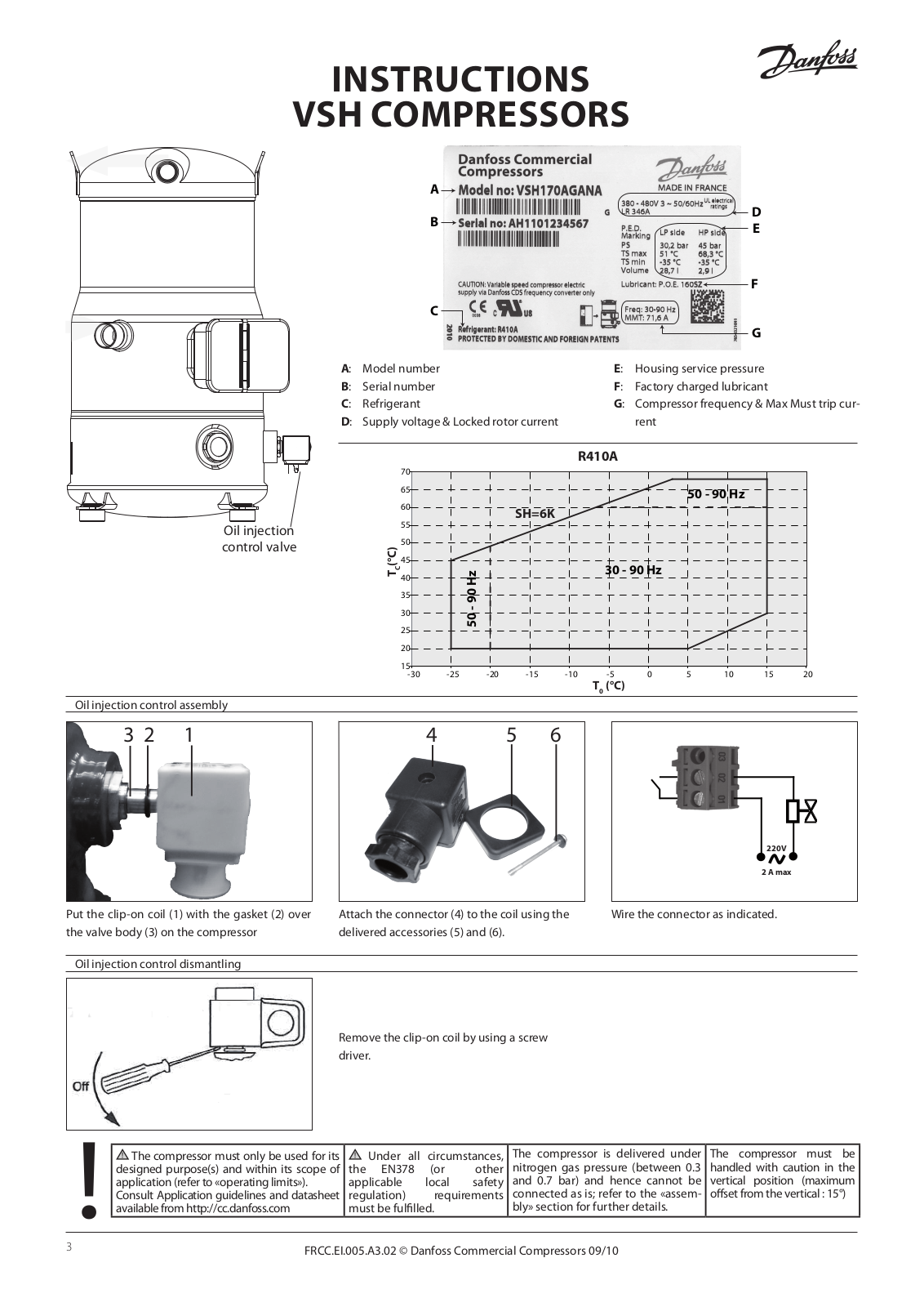
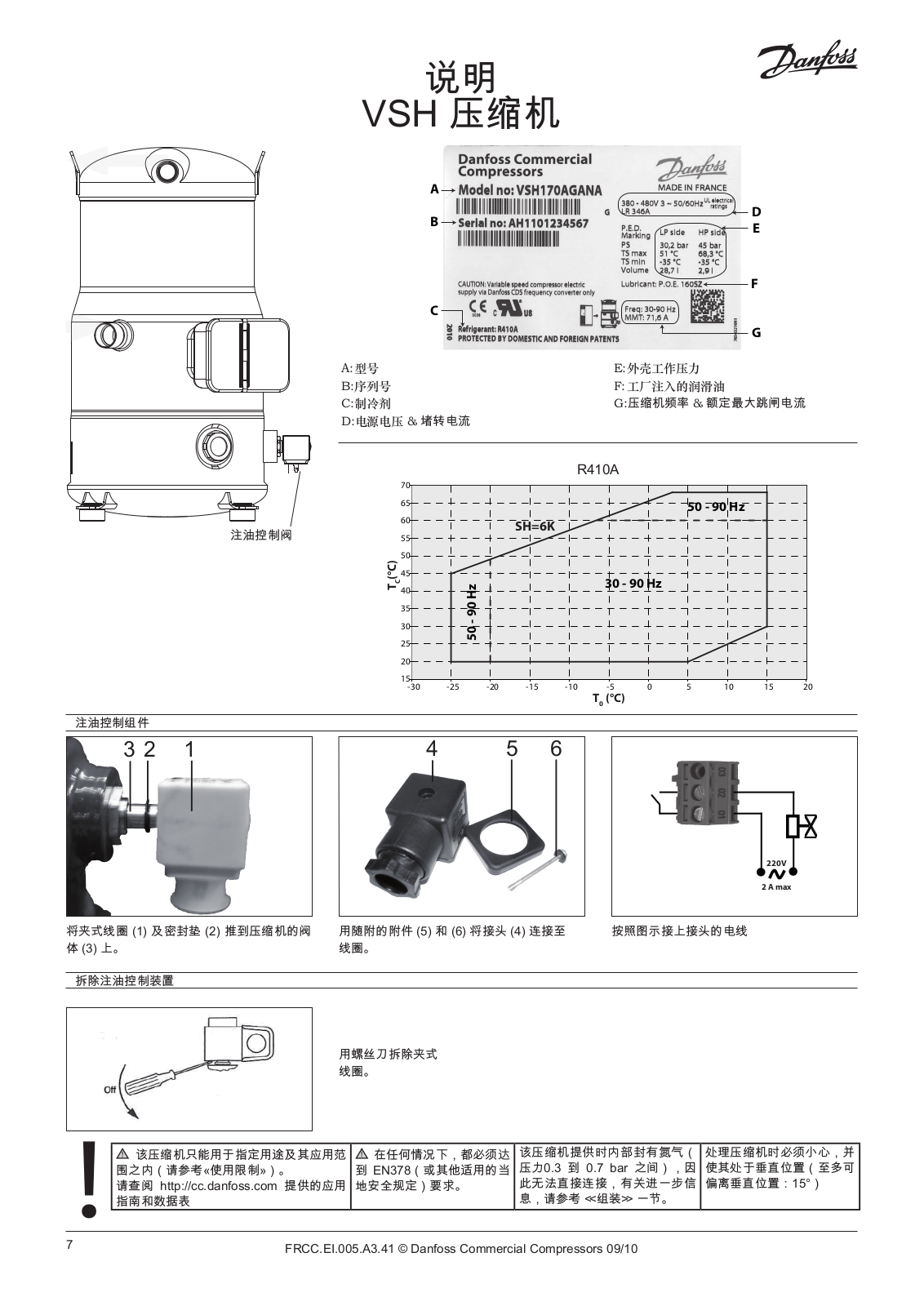
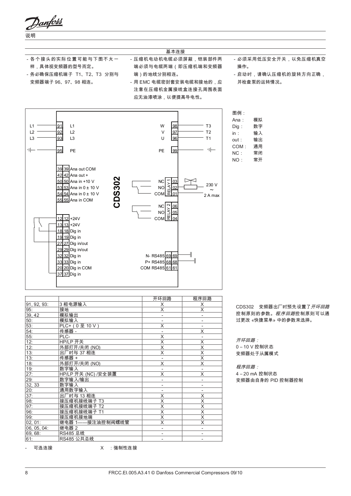
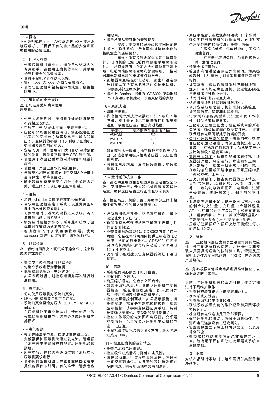
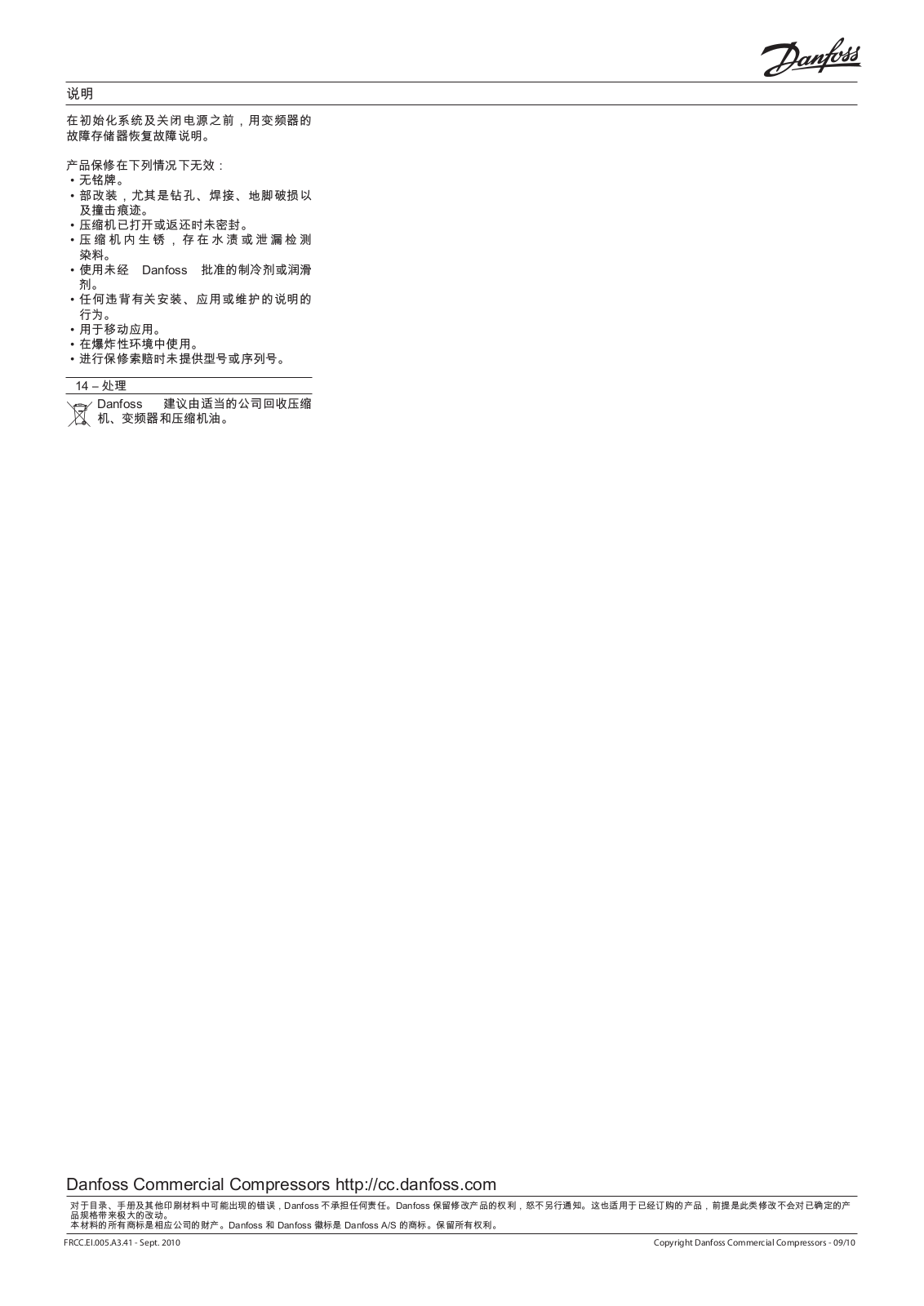
VSH170AGANA
8
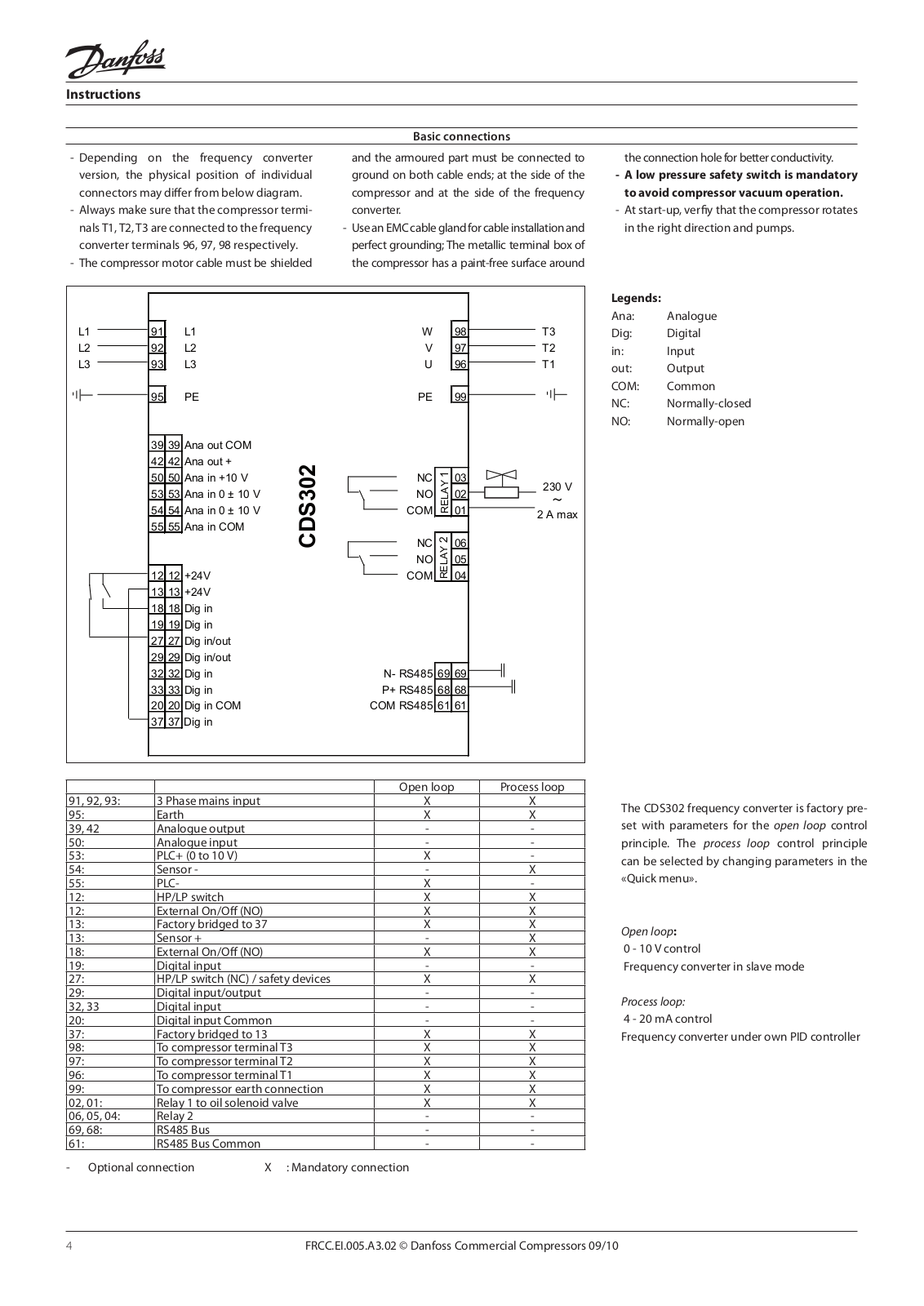
VSH scroll compressors with frequency control for air conditioning systems
VSP
VSP 100
VSP 125
VSP 160
VSP 200
VSP 250
VSP 315
VSP 400
VSP 50
VSP 70
VSP 80
VSPP
3
VT2800 Series
VTA 572
VTC 500
VTC 511
VTZ
VVS
VVX
2
VVX-B
5
VVX-B HWP
VVX Compact
VVX Compact 28
7
VVX Compact 28 - 40
VVX-I
2
VVX-ID 22-22
2
VVX-OR
VVX-Q
VX
VX 22
2
VX Akva Lux II 2H
VX Compact 28
4
VX Compact 28 - 40
2
VX Compact 28 HW OP
2
VX Compact – Floor Station
VX SLS
VX SOLO 22
6
VX Solo H OP
VX Solo HWS
2
VX Solo HWS OP
2
VX Solo II
11
VX Solo II H
3
VX Solo II H2
2
VX Solo II H2WP
2
VX Solo II H2WS
2
VX Solo II HOFOR
VX Solo II HWP
2
VX Solo II HWS
2
VX - T24
Loading...
Loading...
Nothing found
VSH170AGANA
Installation guide
4 pgs
803.31 Kb
0
Installation guide [bg]
32 pgs
2.52 Mb
0
Installation guide [cs]
4 pgs
783.32 Kb
0
Installation guide [da]
4 pgs
791.29 Kb
0
Installation guide [de]
4 pgs
793.45 Kb
0
Installation guide [el]
4 pgs
801.84 Kb
0
Installation guide [sv]
4 pgs
789.98 Kb
0
Installation guide [zh]
4 pgs
1.1 Mb
0
Table of contents
Loading...
Danfoss VSH170AGANA Installation guide [bg]
...
Danfoss Installation guide [bg]
Download
Specifications and Main Features
Frequently Asked Questions
User Manual
Download
Loading...
+
hidden pages
Unhide
You need points to download manuals.
1 point = 1 manual.
You can buy points or you can get point for every manual you upload.
Buy points
Upload your manuals