

Page 1
Data sheet
Pressure relief valve
VRH 5 / VRH 30 / VRH 60 / VRH 120
hpp.danfoss.com
Page 2

Data sheet | Pressure relief valve, type VRH 5, VRH 30, VRH 60 and VRH 120
Table of Contents
Contents
1. Introduction ............................................................................2
2. Features ................................................................................2
3. Variants.................................................................................2
4. Technical data ..........................................................................3
5. Flow ....................................................................................3
5.1 VRH 5 Max. ow 5 l/ min. ................................................................3
5.2 VRH 30 Max. ow 30 l/min. ..............................................................4
5.3 VRH 60 Max. ow 60 l/min. ..............................................................4
5.4 VRH 120 Max. ow 120 l/min. ............................................................5
5.5 VRH 120 F Max. ow 120 l/min............................................................5
6. Mounting ...............................................................................6
7. Operation...............................................................................6
8. Dimensions .............................................................................7
9. Spare parts .............................................................................8
1. Introduction
2. Features • Excellent functional characteristics.
3. Variants
The relief valve is used for protecting the components of a system against overload as a result of a
pressure peak.
Further, the valve is designed for controlling/
limiting the system pressure by draining o the
surplus water from the pressure side.
• Surface easy to clean.
• Corrosion-proof parts (stainless steel,
AISI 304, W. No. 1.4301).
The valves are available in four sizes:
• 5 l/min.
• 30 l/min.
• 60 l/min.
• 120 l/min.
The valve is designed for tap water, i.e. without
additives of any kind to the medium.
(EU-drinking water directive 98/83/EC).
Standard versions made of rustproof steel AISI
304/W. No. 1.4301. Upon request also available in
versions made of stainless steel AISI 316L/W No.
1.4401
The relief valves are available with dierent
pressure ranges.
© Danfoss | DCS (im) | 2020.03
AI24658650288en-001401 | 521B084 | 2
Page 3
0
10
20
30
40
50
60
70
80
90
100
110
120
130
140
150
0 1 2 3 4 5
P [Bar]
Q [l/min]
Data sheet | Pressure relief valve, type VRH 5, VRH 30, VRH 60 and VRH 120
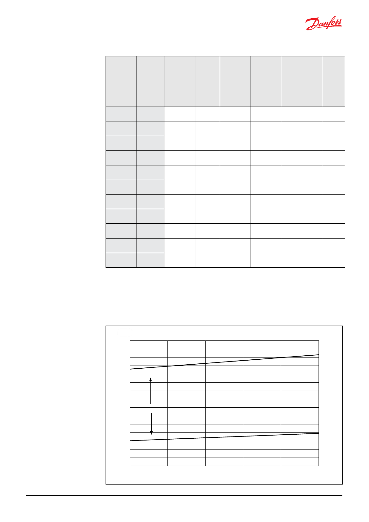
4. Technical data
Setting
screw
(min. to
max.)
mm
(inch)
Typ e Code no.
Pressure
range
barg (psig)
Flow (max.)
l/min.
(gpm)
Media and
ambient
temperature
°C (°F)
Internal leakage
20% below
max.. setting
pressure
l/min. (gpm)
Weight
kg (lbs)
VRH 5 180G 0034
VRH 5 CA1)180G0033
VRH 30 180G0030
VRH 30 180G0029
VRH 30 180G0031
VRH 30 CA1)180G0032
VRH 60 180G0002
VRH 60 180G0003
VR H 120 180G0020
VR H 120 180G0021
VRH 120 F2)180G0035
1)
Cartridge version
2)
Fire ghting version - recommended inspection after 500 hours of operation
30 -120
(435-1740 )
30 -120
(435-1740 )
25 -140
(362-2030)
10- 40
(145 -580 )
45-210
(652-3045)
25 -140
(362-2030)
25-80
(3 62-116 0)
80 -140
(1160-2030)
25-80
(3 62-116 0)
80 -140
(1160-2030)
80 -140
(1160-2030)
5.3
(0.2)
5.3
(0.2)
5.3
(0.2)
5.3
(0.2)
5.3
(0.2)
5.3
(0.2)
5
(1.3)
5
(1.3)
30
(7. 9)
30
(7. 9)
30
(7. 9)
30
(7. 9)
6.2
(0.24)60(15. 8)
6.2
(0.24)60(15. 8)
7.3
(0.28)
7.3
(0.28)
7.3
(0.28)
120
(31.7)
120
(31.7)
120
(31.7)
50
(122)
50
(122)
50
(122)
50
(122)
50
(122)
50
(122)
50
(122)
50
(122)
50
(122)
50
(122)
50
(122)
up to 0.3
(up to 0.08)
up to 0.3
(up to 0.08)
up to 0.3
(up to 0.08)
up to 0.3
(up to 0.08)
up to 0.3
(up to 0.08)
up to 0.3
(up to 008)
up to 1.0
(up to 0.3)
up to 1.0
(up to 0.3)
up to 1.0
(up to 0.3)
up to 1.0
(up to 0.3))
up to 1.0
(up to 0.3)
0.62
(1.5)
0.62
(1.5)
0.62
(1.5)
0.62
(1.5)
0.62
(1.5)
0.62
(1.5)
1.3
(2.4)
1.3
(2.4)
2.8
(6.2)
2.8
(6.2)
2.8
(6.2)
5. Flow 5.1 VRH 5 Max. ow: 5 l/min.
Pressure setting range: 30-140 barg (435-1740 psig)
© Danfoss | DCS (im) | 2020.03
30 to 120
AI24658650288en-001401 | 521B0841 | 3
Page 4

Data sheet | Pressure relief valve, type VRH 5, VRH 30, VRH 60 and VRH 120
5.2 VRH 30 Max. ow: 30 l/min.
Pressure setting range: 10-40 barg, 25-140 barg, 45-210 barg
(145-180 psig, 362-2030 psig, 652-3045 psig)
10 - 40
5.3 VRH 60 Max. ow: 60 l/min.
Pressure setting range: 25-80 barg, 80-140 barg
(362-1160 psig, 1160-2030 psig)
© Danfoss | DCS (im) | 2020.03
AI24658650288en-001401 | 521B084 | 4
Page 5

0
20
40
60
80
100
120
140
160
180
0 20 40 60 80 100 120
P [Bar]
Q [l/min]
Data sheet | Pressure relief valve, type VRH 5, VRH 30, VRH 60 and VRH 120
5.4 VRH 120 Max. ow: 120 l/min.
Pressure setting range: 25-80 barg, 80-140 barg
(362-1160 psig, 1160-2030 psig)
5.5 VRH 120F Max. ow: 120 l/min.
Pressure setting range: 80-140 barg
(1160-2030 psig)
80 to 140
© Danfoss | DCS (im) | 2020.03
AI24658650288en-001401 | 521B084 | 5
Page 6

Data sheet | Pressure relief valve, type VRH 5, VRH 30, VRH 60 and VRH 120
6. Mounting The valve is mounted in-line and xed by means
7. Operation
of the system’s piping or fastened (only VRH 120)
by means of the two 8.4 mm holes in the valve.
It is important that valve is bleed to avoid noise
and therefore must the valve be mounted in the
correct position - please see drawing
Starting up
To ensure stable working conditions for the valve
it is very important to bleed the valve during
starting up.
Noise level
Since the valve typically is mounted in-line or on
a frame, the noise level can only be determined
for the complete system, It is therefore very
important that the valve is mounted correctly on
a frame to minimize vibrations and noise.
The noise level is inuenced by:
• Mounting position of the valve is important to
ensure a good bleeding of valve.
• Sucient bleeding of the valve.
• High pressure generates more noise that low
pressure.
• Rigid mounting of the valve generates mor
noise than exible mounting.
• Pipe mounting direct to the valve increases
the noise level compared to a exible hose
connection.
Filtration
We strongly recommend that you always use
precision depth lter cartridges in the system,
rated 10 μm abs. β10 ≥ 5,000. or better.
Corrosion and frost protection
If the valve is exposed to temperature below
freezing, it must be protected against freezing.
Danfoss recommends DOWCAL N or Zitrec FC
antifreezes both being biologically degradable
Mono Propylene Glycol (MPG).
© Danfoss | DCS (im) | 2020.03
AI24658650288en-001401 | 521B084 | 6
Page 7

Data sheet | Pressure relief valve, type VRH 5, VRH 30, VRH 60 and VRH 120
8. Dimensions
Typ e A B C D E F G1G2H J K L M N O P R
VRH 5 109.6 89.2 AF4 AF13 98.2 33.5 16. 8 18 42 G3/8 - 25 10 36 - - 12
VRH 30 109.6 89.2 AF4 AF13 98.2 33.5 16.8 18 42 G3/8 - 25 10 36 - - 12
VRH 60 151 117 AF5 AF19 129 42.5 21.2 21.2 55.5 G1/2 - 33 14 45 - - 21.5
VR H 120 202 165.5 AF8 AF24 182.5 60 30 30 75 G3/4 43 46.5 15 65 Ø8.4 20 30.4
VR H 120 F 202 165.5 AF8 AF24 182.5 60 30 30 75 G3/4 43 46.5 15 65 Ø8.4 20 30.4
8.1 VRH 5, VRH 30, VRH 60 and VRH 120
8.2 VRH 5 CA and VRH 30 CA
© Danfoss | DCS (im) | 2020.03
AI24658650288en-001401 | 521B084 | 7
Page 8

9. Spare parts
Valve size Description Code no.
VRH 5 Valve seat and cone kit 25-100 barg (362-1450 psig) 180G4 018
VRH 5 Seal and spring kit 180G4019
VRH 30 Valve seat and cone kit [pressure range 10-40, 25-140 barg (145-580, 362-2030 psig)] 180G4000
VRH 5/30 Guide and guide pin kit 180G4001
VRH 30 Seal and spring kit [pressure range 10-40 barg (145-580 psig)] 180G4002
VRH 5/30 To ol kit 180G4003
VRH 30 Seal and spring kit [pressure range 25-140, 45-210 barg (362-2030, 652-3045 psig)] 180G4004
VRH 30 Valve seat and cone kit [pressure range 45-210 barg (652-3045 psig)] 180G4005
VRH 60 Valve seat and cone kit [pressure range 10-140 barg (145-2030 psig)] 180G4006
VRH 60 Guide and guide pin kit 180G4007
VRH 60 Seal and spring kit [pressure range 10-40 barg (145-580 psig)] 180G4008
VRH 60 Seal and spring kit [pressure range 25-60 barg (362-1160 psig)] 180G4009
VRH 60 Seal and spring kit [pressure range 80-140 barg (1160-2030 psig)] 180G4010
VRH 60 Tool kit 180G4011
VRH 120 Valve seat and cone kit [pressure range 25-140 barg (362-2030 psig)] 180G4012
VRH 120 Guide and guide pin kit 180G4013
VRH 120 Seal and spring kit [pressure range 25-80 barg (362-1160 psig)] 180G4014
VRH 120 Seal and spring kit [pressure range 80-140 barg (1160-2030 psig)] 180G4015
VRH 120 To ol kit 180G4016
VRH 120 F Valve seat and cone kit [pressure range 80-140 barg (1160-2030 psig)] 180G4020
9.1 Recommendation for build in a VRH 5/30 CA
Danfoss A/S
High Pressure Pumps
DK-6430 Nordborg
Denmark
Danfoss ca n accept no respons ibility for pos sible errors in ca talogues, bro chures and other pr inted material. Da nfoss reserves t he right to alter its p roducts with out notice.
This also a pplies to produc ts already on ord er provided that su ch alterations ca n be made without su bsequential cha nges being nece ssary in speci cations alread y agreed.
All trade marks in this mate rial are proper ty of the respec tive companies . Danfoss and the Dan foss logotyp e are trademark s of Danfoss A/S. Al l rights reserv ed.
© Danfoss | DCS (im) | 2020.03
AI24658650288en-001401 | 521B084 | 8
 Loading...