

Page 1
Data sheet
Seated valves (PN 16)
VRG 2 – 2-way valve, external thread
VRG 3 – 3-way valve, external thread
Description
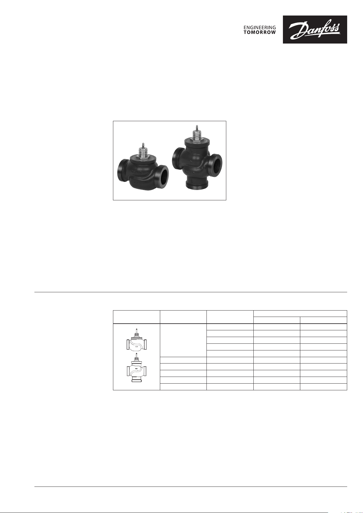
VRG 3VRG 2
VRG valves provide a quality, cost effective
solution for most water and chilled applications.
The valves are designed to be combined with
following actuators:
• With AMV(E) 335, AMV(E) 435 or AMV(E) 438
SU actuators.
• With AMV(E) 25, 25 SU/SD, 35 actuators (with
adapter 065Z0311).
Combinations of actuators is evident under
section “Dimension”.
Features:
• Bubble tight design
• Snap mechanical connection together with
AMV(E) 335, AMV(E) 435
• Dedicated 2-port valve
• Suitable for diverting applications (3-port)
Main data:
• DN 15-50
• kVS 0.63 -40 m3/h
• PN 16
• Temperature:
- Circulation water / glycolic water up to 50 %:
2 (–10*) … 130 °C
* At temperatures from 10 °C up to +2 °C use stem heater
• Connections:
- External thread
Ordering
Example:
3-way valve; DN 15; kVS 1.6 ; PN 16;
T
130 °C; ext. thread
max
- 1× VRG 3 DN 15 valve
Code No.: 0 65 Z011 3
Option:
- 3× Tailpieces
Code No.: 06 5Z0291
2 & 3-way valves VRG (external thread)
Picture DN
15
20 6.3 065Z0136 06 5Z0116
25 10 065 Z0137 06 5Z0 117
32 16 06 5Z0138 0 65Z 0118
40 25 06 5Z0139 065Z0119
50 40 06 5Z0140 0 65Z0 120
kVS
(m3/h)
0.63 06 5Z0131 06 5Z0111
1.0 06 5Z0132 06 5Z0112
1.6 06 5Z0133 06 5Z0113
2.5 065Z 0134 065Z 0114
4.0 065Z 0135 065 Z011 5
VRG 2 VRG 3
Code No.
© Danfoss | 2021.06 AI157486475069en-010503 | 1
Page 2
Data sheet Seated valves VRG 2, VRG 3
Ordering (continued)
Technical data
Accessories - Tailpieces
Typ e DN Code No.
Rp ½ 15 065Z0291
Rp ¾ 20 065Z0292
Rp 1 25 065Z0293
1)
Tailpiece
1)
1 tailpiece inter nal thread for VRG ext . thread (Ms - CuZn39Pb3)
Nominal diameter DN 15 20 25 32 40 50
kVS value m3/h 0.63 1.0 1.6 2.5 4.0 6.3 10 16 25 40
Stroke mm 10 15
Control range 30:1 50:1 100 :1
Control characteristic LOG: port A-AB; LIN: por t B-AB
Cavitation factor z ≥ 0.4
Leakage
Nominal pressure PN 16
Max. closing pressure bar
Medium Circulation water / glycolic water up to 50 %
Medium pH Min. 7, Max. 10
Medium temperature °C 2 (–10 1) ) … 130
Connections ext. thread
Materials
Valve body Grey cast iron EN-GJL-250 (GG-25)
Valve stem Stainless steel
Valve cone Brass
Stuffing box sealing EPDM
1)
At temperature s from -10 up to +2 °C use stem heate r
Rp 1¼ 32 065Z0294
Rp 1½ 40 065Z0295
Rp 2 50 065Z0296
Accessories - Adapter & stem heater
Typ e for actuators Code No.
Adapter AMV(E) 25/35 065 Z0311
Stem heater AMV(E) 335/435 0 65Z0315
Service kits
Typ e DN Code No.
15 0 65Z0321
20 065Z0322
Stuffing box
A - AB bubble tight design
B - AB ≤ 1.0 % of kVS
Mixing: 4
Diverting: 1
25 065Z0323
32 065Z0324
40/50 065Z0325
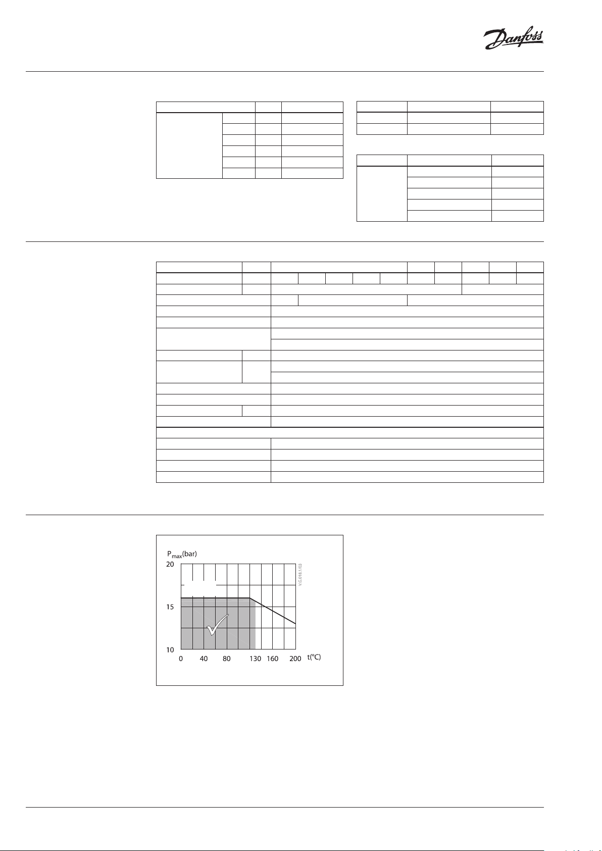
Pressure temperature
diagram
PN 16
EN -GJ L-25 0
(GG -25)
Maximum allowed operating pressure as a function of
medium temperature.
2 | AI157486475069en-010503 © Danfoss | 2021.06
Page 3
Data sheet Seated valves VRG 2, VRG 3
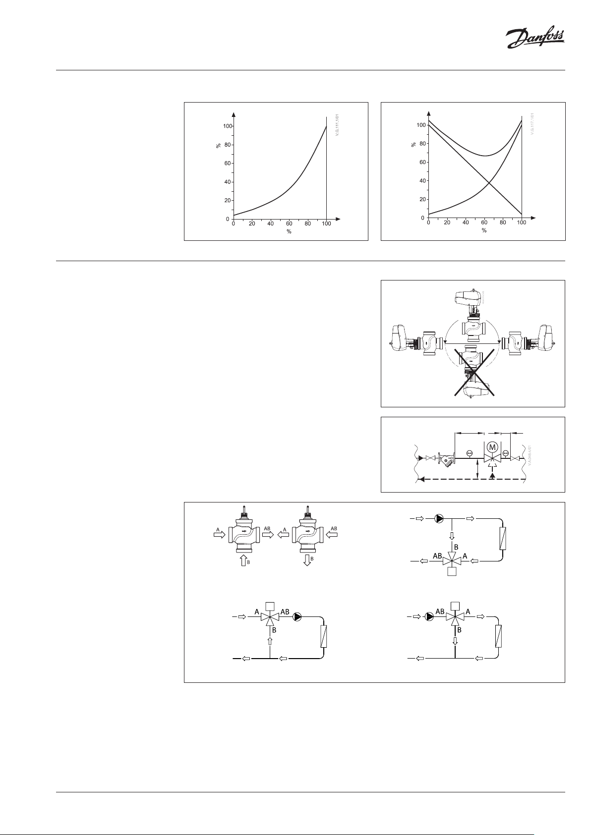
Valve characteristics
Valve characteristics log (2-way) Valve characteristics log/lin (3-way)
Capacity
Installation Valve mounting
Before valve mounting the pipes have to be
cleaned and free from abrasion. Valve must
be mounted according to flow direction as
indicated on valve body except by diverting,
where valve can be mounted oposite to the
flow direction (flow oposite to indication on
the valve body). Mechanical loads of the valve
body caused by the pipes are not allowed. Valve
should be free of vibrations as well.
Stroke
A+BAB
B
A
Stroke
AB
B
A
Capacity
B
A
A
Note:
Install a strainer upstream of the
valve (e.g. D anfoss FVR/ FVF)
Installation of the valve with the actuator is
allowed in horizontal position or upwards.
Installation downwards is not allowed.
Always install the valve with the arrow on
the body in the same direction as the flow. In
order to avoid turbulence, which will affect the
measuring accuracy, it is recommended to have a
straight length of pipe up and down stream from
the valve as shown (D - diameter of pipe).
Mixing Diverting
Fig. 1: Mixing or diverting connection
Fig. 2: Mixing valve used in mixing application
5D
FVR/FVF
2D
AMV(E)
5D
Fig. 3: Mixing valve used in diver ting application
Fig. 4: Diverting valve used in diverting application
Mixing or diverting connection
3-way valve can be used either as mixing or
diverting valve (fig.1).
If 3-way valve is installed as mixing valve
meaning that A and B ports are inlet ports, and
AB port is outlet port it can be installed in mixing
(fig.2) or diverting application (fig.3).
3-way valve can be also installed as diverting
valve in diverting application (fig.4) meaning that
AB port is inlet and A and B ports are outlets.
Note:
Maximal closing pressure for mixing and diverting
insta llation are no t the same. Plea se refer to value s stated
in Technical data section.
AI157486475069en-010503 | 3© Danfoss | 2021.06
Page 4

Data sheet Seated valves VRG 2, VRG 3
21
1
pp
p
a authority, Valve
∆+∆
∆
=
5.0
pp
p
a
21
1
=
∆−∆
∆
=
62.0
557.90
7.90
autority valve hance =
+
=
395.0
5536
36
autority value hence =
+
=
Sizing
Flow Rate
(liquid with specific a gravity of 1)
l/sec m3/h
max
p
FLOW Pressure drop kPa (100 kPa = 1bar = ~ 10 m H2O)
Example
Design data:
Flow rate: 6 m3/h
System pressure drop: 55 kPa
Locate the horizontal line representing a flow
rate of 6 m3/h (line A-A). The valve authority is
given by the equation:
Where:
p1 = pressure drop across the fully open
valve
p2 = pressure drop across the rest of the
circuit with a full open valve
The ideal valve would give a pressure drop equal
to the system pressure drop (i.e. an authority of
0.5 ):
if: p1 = p
2
In this example an authority of 0.5 would be
given by a valve having a pressure drop of
55 kPa at that flow rate (point B). The intersection
of line A–A with a vertical line drawn from B lies
between two diagonal lines; this means that no
ideally-sized valve is available.
The intersection of line A–A with the diagonal
lines gives the pressure drops stated by real,
rather than ideal, valves. In this case, a valve with
kVS 6.3 would give a pressure drop of 90.7 kPa
(point C):
The second largest valve, with kVS 10, would give
a pressure drop of 36 kPa (point D):
Generally, for a 3 port application, the smaller
valve would be selected (resulting in a valve
authority higher than 0.5 and therefore
improved control). However, this will increase
the total pressure and should be checked by the
system designer for compatibility with available
pump heads, etc. The ideal authority is 0.5 with a
preferred range of between 0.4 and 0.7 .
4 | AI157486475069en-010503 © Danfoss | 2021.06
Page 5

Data sheet Seated valves VRG 2, VRG 3
6
7
Design
(Design variati ons are possible)
VRG 2
1. Valve body
2. Valve insert
3. Valve cone
4. Valve stem
5. Moving valve seat
(pressure relieved)
6. Stuffing box
VRG 3
1. Valve body
2. Valve insert
3. Valve cone
4. Valve stem
5. Valve seat
6. Pressure relieve chamber
7. Stuffing box
AI157486475069en-010503 | 5© Danfoss | 2021.06
Page 6

Data sheet Seated valves VRG 2, VRG 3
Dimensions
Rp
(see ordering
part acc essories,
page 2)
Rp
(see ordering
part acc essories,
page 2)
Min 20.5
L
1
1
H
A
H
L
AMV(E) 335, 435 + VRG 2
Min 20.5
2
H
L
1
A
1
H
A
2)
G
Typ e DN
VRG 2
VRG 3
1)
G … extern al thread DIN ISO 228/01
If stem heater is use d dimension H1 is increased for 31 mm.
Connection L H H
1)
G
15 1 80 29 191 128
20 1⁄ 80 31 193 128 0.78
25 1⁄ 95 32 197 151 1. 07
32 2 112 35 201 178 1.48
40 2⁄ 132 45 213 201 2.60
50 2 ¾ 160 48 217 234 3.64
15 1 80 40 191 128 64 0.71
20 1⁄ 80 45 193 12 8 69 0.90
25 1⁄ 95 50 196 151 78 1.22
32 2 112 58 201 178 91 1.82
40 2⁄ 132 75 230 201 110 3.17
50 2 ¾ 160 83 243 234 120 5.01
mm
AMV(E) 335, 435 + VRG 3
L
1
H
1
H
L
Weight
2
(kg)
0.66
-
6 | AI157486475069en-010503 © Danfoss | 2021.06
Page 7

Data sheet Seated valves VRG 2, VRG 3
Dimensions (continued)
Min 100
Min 100
A
L
AMV(E) 438 SU + VRG 2
AMV(E) 25/35 + VRG 2 +
adapter 065Z0311
Typ e DN
VRG 2
VRG 3
1)
G … extern al thread DIN ISO 228/01
If stem heater is use d dimension H1 is increased for 5 m m.
A
1
H
2)
G
H
Connection
1)
G
15 1 80 29 216
20 1⁄ 80 31 218
25 1⁄ 95 32 222
32 2 112 35 226
40 2⁄ 132 45 237
50 2 ¾ 160 48 242
15 1 80 40 216
20 1⁄ 80 45 218
25 1⁄ 95 50 222
32 2 112 58 226
40 2⁄ 132 75 255
50 2 ¾ 160 83 268
L H H
mm
A
L
AMV(E) 438 SU + VRG 3
AMV(E) 25/35 + VRG 3 +
adapter 065Z0311
1
1
H
H
AI157486475069en-010503 | 7© Danfoss | 2021.06
Page 8

Data sheet Seated valves VRG 2, VRG 3
© Danfoss | DCS-S/SI | 2021.068 | AI157486475069en-010503
 Loading...