

Data sheet
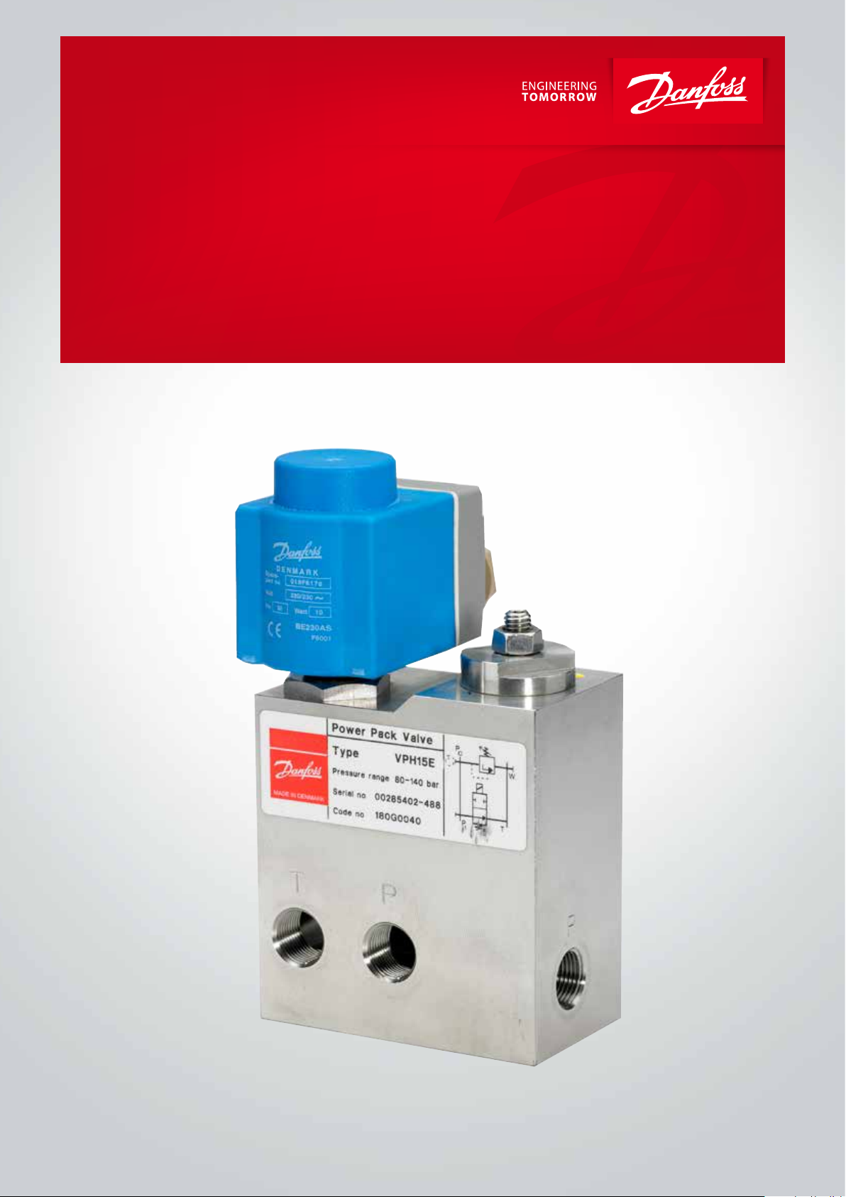
Power Pack Valve
VPH 15E
hpp.danfoss.com
Data sheet | Power Pack Valve type VPH 15 E
Table of Contents Contents
1. Introduction ……………………………………………………………………………………………2
2. Features…………………………………………………………………………………………………2
3. Technical data………………………………………………………………………………………… 2
4. Description…………………………………………………………………………………………… 4
5. Filtration……………………………………………………………………………………………… 4
6. Code numbers………………………………………………………………………………………… 4
7. Dimensions [mm]………………………………………………………………………………………5
8. Installation…………………………………………………………………………………………… 5
9. Spare parts…………………………………………………………………………………………… 6
1. Introduction
2. Features
3. Technical data
Power Pack valve VPH 15 E is multifunction unit
which reduces the costs of connections and
hoses/tubes by incorporating the functions of a
The valves are electrically-activated ON/OFF
valves (closed (NC) or open (NO) when the coil is
de-energized).
pressure relief valve and a directional control
valve to provide a bypass function.
The VPH 15 E valve is designed for use with
drinking water, i.e. water containing no additives
The pressure relief function is designed to limit
the system pressure by draining surplus water
of any kind. (See EU drinking water directive EU
98/83/EC).
ow from the pressure side, and to protect
system components against overload as a result
of pressure peaks.
• High enclosure, IP 67
• Corrosion-proof materials (stainless
• The seat valve design ensures a tight seal
• Easy-to-clean surfaces.
steel, AISI 304/W.No. 1.4301 and plastic)
Adjustable pressure range 10-210 bar
Nom. ow 15 l/min
Max. ow 20 l/min
Max. uid temperature 50°C
Opening time at nom. ow 90 ms
Closing time at nom. ow 350 ms
Pressure drop see graph page 3
Weight 3 kg
Ambient temperature 0°C to +50°C
Fluid temperature
Storage temperature -40°C to +70°C
1)
At uid temperature below +3°C, antifreeze additives must be added to uid.
1)
-30°C to +50°C
2 | © Danfoss | DCS (im) | 2020.02
AI317748505469en-001001 | 521B0811

Data sheet | Power Pack Valve type VPH 15 E
Relief valve
Max. ow: 20 l/min
Pressure setting range: 10 to 40 bar, 25 to 140 bar, 45 to 210 bar
P/Q
characteristic
2/2-way valve
Max. ow: 20 l/min
Max. pressure for NO: 140 bar
Max. pressure for NC: 210 bar
Static characteristic:
Pressure drop
(P->T, bypass function)
© Danfoss | DCS (im) | 2020.02 AI317748505469en-001001 | 521B0811 | 3

Data sheet | Power Pack Valve type VPH 15 E
4. Description
5. Filtration
VPH 15 E - NO VPH 15 E - NC
P: G ³⁄ – pressure from
T: G ³⁄ – tank return line
M: G ³⁄ (plugged)
W: G ¹⁄ (plugged) – water
No. Item Description
1 Directional valve 2/2-way valve, electrically activated
2 Pressure relief valve Manuel setting
3 Power pack valve Directional valve + relief valve
The water supplied to the valve must be ltered:
10 µm abs., β
-value > 5000 lter is recom-
10
mended.
pump or pressure line
to system
from system or return
line to lter
– pressure gauge
inlet
6. Code numbers
Power pack valve Comments Code No.
VPH 15 E - NO Pressure range 25 to 140 bar 180G0040
VPH 15 E - NC Pressure range 25 to 140 bar 180G0041
VPH 15 E - NC Pressure range 45 to 210 bar 180G0044
VPH 15 E - NO Pressure range 10 to 40 bar 180G0042
* Coils for bypass valve, please order seperately
Coil
24 V/50 Hz/12 W
220 V/50 Hz/12 W
240 V/50 Hz/11 W
24 V/60 Hz/14 W
220 V/60 Hz/13 W
240 V/60 Hz/15 W
110 V/50/60 Hz/15 W
12 V d.c./15 W
24 V d.c./16 W
For other voltages, please contact Danfoss Sales Organisation for High-Pressure Pumps.
Coils (clip-on)
(NC + NO)
018F7920
018F7921
018F7924
018F7922
018F7925
018F7926
018F7923
018F7913
018F7914
4 | © Danfoss | DCS (im) | 2020.02
AI317748505469en-001001 | 521B0811

Data sheet | Power Pack Valve type VPH 15 E
7. Dimensions [mm]
VPH 15 E
P : G 3/8 Pressure
T : G 3/8 Pressure
W : G 1/4 Filling
8. Installation
The valve must be installed as illustrated below.
Mounting direction
© Danfoss | DCS (im) | 2020.02 AI317748505469en-001001 | 521B0811 | 5

9. Spare parts
For the directional valve function
Armature kit NC
Armature kit NC (210 bar) (for 180G0044)
Armature kit NO
Orice kit for VPH 15 E
Poppet kit for VPH 15 E
For the relief valve function
Valve seat and cone kit (10-40 bar) & (25-140 bar)
Valve seat and cone kit (45-210 bar)
Seal and spring kit (10-40 bar)
Seal and spring kit (25-140 bar) & (45-210 bar)
Guide and guide pin
Tool for dismount guide
Code number
180L5002
180L5011
180L5010
180Z0099
180L5005
180G4000
180G4005
180G4002
180G4004
180G4001
180G4003
Danfoss A/S
High Pressure Pumps
Nordborgvej 81
DK-6430 Nordborg
Denmark
© Danfoss | DCS (im) | 2020.02
AI317748505469en-001001 | 521B0811 | 6
 Loading...