

Page 1

VLT® HVAC Drive Design Guide Contents
Contents
1. How to Read this Design Guide
Copyright, Limitation of Liability and Revision Rights 3
Approvals 4
Symbols 4
Abbreviations 5
Definitions 5
2. Introduction to VLT HVAC Drive
Safety 11
CE labelling 12
Air humidity 13
Aggressive Environments 14
Vibration and shock 14
VLT HVAC Drive Controls 28
PID 30
General aspects of EMC 39
Galvanic isolation (PELV) 41
PELV - Protective Extra Low Voltage 41
3
11
Control with brake function 42
Extreme running conditions 45
Safe Stop 48
3. VLT HVAC Drive Selection
Options and Accessories 51
4. How to Order
Ordering Numbers 63
5. How to Install
Mechanical Dimensions 72
Electrical Installation 79
Final Set-Up and Test 104
Additional Connections 106
DC bus connection 106
Brake Connection Option 106
Relay Connection 107
Installation of misc. connections 111
51
61
71
Safety 113
EMC-correct Installation 114
Mains supply interference/Harmonics 118
Residual Current Device
MG.11.B7.02 - VLT® is a registered Danfoss trademark
118
1
Page 2

Contents VLT® HVAC Drive Design Guide
6. Application Examples
Start/Stop 119
Pulse Start/Stop 119
Potentiometer Reference 120
Automatic Motor Adaptation (AMA) 120
Smart Logic Control Programming 120
SLC Application Example 121
BASIC Cascade Controller 122
Pump Staging with Lead Pump Alternation 123
System Status and Operation 123
Fixed Variable Speed Pump Wiring Diagram 124
Lead Pump Alternation Wiring Diagram 124
Cascade Controller Wiring Diagram 124
Start/Stop conditions 125
7. RS-485 Installation and Set-up
RS-485 Installation and Set-up 127
FC Protocol Overview 129
119
127
Network Configuration 130
FC Protocol Message Framing Structure 130
Examples
Modbus RTU Overview 135
Modbus RTU Message Framing Structure 137
How to Access Parameters 140
Examples 142
Danfoss FC Control Profile 148
8. General Specifications and Troubleshooting
General Specifications 153
Efficiency 164
Acoustic noise 165
Peak voltage on motor 165
Special Conditions 166
Alarms and warnings 167
Alarm words 171
Warning words 172
134
153
Extended status words 173
Fault messages 174
Index
2
MG.11.B7.02 - VLT® is a registered Danfoss trademark
177
Page 3

VLT® HVAC Drive Design Guide 1. How to Read this Design Guide
1. How to Read this Design Guide
1
VLT HVAC Drive
FC 100 Series
Software version: 2.8.x
This guide can be used with all VLT HVAC Drive frequency converters
with software version 2.8.x.
The actual software version number can be read from
par. 15-43 Software
1.1.1. Copyright, Limitation of Liability and Revision Rights
This publication contains information proprietary to Danfoss. By accepting and using this manual the user agrees that the information contained herein
will be used solely for operating equipment from Danfoss or equipment from other vendors provided that such equipment is intended for communication
with Danfoss equipment over a serial communication link. This publication is protected under the Copyright laws of Denmark and most other countries.
Danfoss does not warrant that a software program produced according to the guidelines provided in this manual will function properly in every physical,
hardware or software environment.
Although Danfoss has tested and reviewed the documentation within this manual, Danfoss makes no warranty or representation, neither expressed nor
implied, with respect to this documentation, including its quality, performance, or fitness for a particular purpose.
In no event shall Danfoss be liable for direct, indirect, special, incidental, or consequential damages arising out of the use, or the inability to use information
contained in this manual, even if advised of the possibility of such damages. In particular, Danfoss is not responsible for any costs, including but not
limited to those incurred as a result of lost profits or revenue, loss or damage of equipment, loss of computer programs, loss of data, the costs to substitute
these, or any claims by third parties.
Version
.
Danfoss reserves the right to revise this publication at any time and to make changes to its contents without prior notice or any obligation to notify former
or present users of such revisions or changes.
MG.11.B7.02 - VLT® is a registered Danfoss trademark
3
Page 4
1. How to Read this Design Guide VLT® HVAC Drive Design Guide
1.1.2. Available Literature
1
- Operating Instructions MG.11.Ax.yy provide the neccessary information for getting the frequency converter up and running.
- Design Guide MG.11.Bx.yy entails all technical information about the frequency converter and customer design and applications.
- Programming Guide MG.11.Cx.yy provides information on how to programme and includes complete parameter descriptions.
- Mounting Instruction, Analog I/O Option MCB109, MI.38.Bx.yy
-
PC-based Configuration Tool MCT 10, MG.10.Ax.yy enables the user to configure the frequency converter from a Windows
ment.
- Danfoss VLT Energy Box software at
- VLT 6000 HVAC Application Booklet, MN.60.Ix.yy
- Operating Instructions VLT HVAC Drive BACnet, MG.11.Dx.yy
- Operating Instructions VLT HVAC Drive Profibus, MG.33.Cx.yy.
- Operating Instructions VLT HVAC Drive Device Net, MG.33.Dx.yy
- Operating Instructions VLT HVAC Drive LonWorks, MG.11.Ex.yy
- Operating Instructions VLT HVAC Drive High Power, MG.11.Fx.yy
- Operating Instructions VLT HVAC Drive Metasys, MG.11.Gx.yy
x = Revision number
yy = Language code
Danfoss technical literature is also available online at
www.danfoss.com/BusinessAreas/DrivesSolutions/Documentations/Technical+Documentation.htm
www.danfoss.com/BusinessAreas/DrivesSolutions
then choose PC Software Download
.
™
based PC environ-
1.1.3. Approvals
1.1.4. Symbols
Symbols used in this guide.
NB!
Indicates something to be noted by the reader.
Indicates a general warning.
Indicates a high-voltage warning.
* Indicates default setting
4
MG.11.B7.02 - VLT® is a registered Danfoss trademark
Page 5
VLT® HVAC Drive Design Guide 1. How to Read this Design Guide
1.1.5. Abbreviations
1
Alternating current AC
American wire gauge AWG
Ampere/AMP A
Automatic Motor Adaptation AMA
Current limit I
Degrees Celsius °C
Direct current DC
Drive Dependent D-TYPE
Electro Magnetic Compatibility EMC
Electronic Thermal Relay ETR
drive FC
Gram g
Hertz Hz
Kilohertz kHz
Local Control Panel
Meter m
Millihenry Inductance mH
Milliampere mA
Millisecond ms
Minute min
Motion Control Tool MCT
Nanofarad nF
Newton Meters Nm
Nominal motor current I
Nominal motor frequency f
Nominal motor power P
Nominal motor voltage U
Parameter par.
Protective Extra Low Voltage PELV
Printed Circuit Board PCB
Rated Inverter Output Current I
Revolutions Per Minute RPM
Regenerative terminals Regen
Second s
Synchronous Motor Speed n
Torque limit T
Volts V
LIM
M,N
M,N
M,N
M,N
INV
s
LIM
1.1.6. Definitions
Drive:
I
VLT,MAX
The maximum output current.
I
VLT,N
The rated output current supplied by the frequency converter.
U
VLT, MAX
The maximum output voltage.
Input:
Control command
You can start and stop the connected motor by means of
LCP and the digital inputs.
Functions are divided into two groups.
Functions in group 1 have higher priority than functions in
group 2.
Motor:
Group 1
Group 2
Reset, Coasting stop, Reset and Coasting stop, Quickstop, DC braking, Stop and the "Off" key.
Start, Pulse start, Reversing, Start reversing, Jog and
Freeze output
f
JOG
The motor frequency when the jog function is activated (via digital terminals).
MG.11.B7.02 - VLT® is a registered Danfoss trademark
5
Page 6

1. How to Read this Design Guide VLT® HVAC Drive Design Guide
f
M
The motor frequency.
1
f
MAX
The maximum motor frequency.
f
MIN
The minimum motor frequency.
f
M,N
The rated motor frequency (nameplate data).
I
M
The motor current.
I
M,N
The rated motor current (nameplate data).
n
M,N
The rated motor speed (nameplate data).
P
M,N
The rated motor power (nameplate data).
T
M,N
The rated torque (motor).
U
M
The instantaneous motor voltage.
U
M,N
The rated motor voltage (nameplate data).
Break-away torque
η
VLT
The efficiency of the frequency converter is defined as the ratio between the power output and the power input.
Start-disable command
A stop command belonging to the group 1 control commands - see this group.
Stop command
See Control commands.
6
MG.11.B7.02 - VLT® is a registered Danfoss trademark
Page 7

VLT® HVAC Drive Design Guide 1. How to Read this Design Guide
References:
Analog Reference
A signal transmitted to the analog inputs 53 or 54, can be voltage or current.
Bus Reference
A signal transmitted to the serial communication port (FC port).
Preset Reference
A defined preset reference to be set from -100% to +100% of the reference range. Selection of eight preset references via the digital terminals.
Pulse Reference
A pulse frequency signal transmitted to the digital inputs (terminal 29 or 33).
Ref
MAX
Determines the relationship between the reference input at 100% full scale value (typically 10 V, 20mA) and the resulting reference. The maximum
reference value set in par. 3-03.
Ref
MIN
Determines the relationship between the reference input at 0% value (typically 0V, 0mA, 4mA) and the resulting reference. The minimum reference value
set in par. 3-02.
Miscellaneous:
Analog Inputs
The analog inputs are used for controlling various functions of the frequency converter.
There are two types of analog inputs:
Current input, 0-20 mA and 4-20 mA
Voltage input, 0-10 V DC.
1
Analog Outputs
The analog outputs can supply a signal of 0-20 mA, 4-20 mA, or a digital signal.
Automatic Motor Adaptation, AMA
AMA algorithm determines the electrical parameters for the connected motor at standstill.
Brake Resistor
The brake resistor is a module capable of absorbing the brake power generated in regenerative braking. This regenerative braking power increases the
intermediate circuit voltage and a brake chopper ensures that the power is transmitted to the brake resistor.
CT Characteristics
Constant torque characteristics used for screw and scroll refrigeration compressors.
Digital Inputs
The digital inputs can be used for controlling various functions of the frequency converter.
Digital Outputs
The frequency converter features two Solid State outputs that can supply a 24 V DC (max. 40 mA) signal.
DSP
Digital Signal Processor.
Relay Outputs:
The frequency converter features two programmable Relay Outputs.
MG.11.B7.02 - VLT® is a registered Danfoss trademark
7
Page 8

1. How to Read this Design Guide VLT® HVAC Drive Design Guide
ETR
Electronic Thermal Relay is a thermal load calculation based on present load and time. Its purpose is to estimate the motor temperature.
1
GLCP:
Graphical Local Control Panel (LCP102)
Initialising
If initialising is carried out (par. 14-22), the programmable parameters of the frequency converter return to their default settings.
Intermittent Duty Cycle
An intermittent duty rating refers to a sequence of duty cycles. Each cycle consists of an on-load and an off-load period. The operation can be either
periodic duty or none-periodic duty.
LCP
The Local Control Panel (LCP) makes up a complete interface for control and programming of the frequency converter. The control panel is detachable
and can be installed up to 3 metres from the frequency converter, i.e. in a front panel by means of the installation kit option.
The Local Control Panel is available in two versions:
- Numerical LCP101 (NLCP)
- Graphical LCP102 (GLCP)
lsb
Least significant bit.
MCM
Short for Mille Circular Mil, an American measuring unit for cable cross-section. 1 MCM 0.5067 mm
2
.
msb
Most significant bit.
NLCP
Numerical Local Control Panel LCP101
On-line/Off-line Parameters
Changes to on-line parameters are activated immediately after the data value is changed. Changes to off-line parameters are not activated until you enter
[OK] on the LCP.
PID Controller
The PID controller maintains the desired speed, pressure, temperature, etc. by adjusting the output frequency to match the varying load.
RCD
Residual Current Device.
Set-up
You can save parameter settings in four Set-ups. Change between the four parameter Set-ups and edit one Set-up, while another Set-up is active.
SFAVM
Switching pattern called
Slip Compensation
The frequency converter compensates for the motor slip by giving the frequency a supplement that follows the measured motor load keeping the motor
speed almost constant..
Stator Flux oriented Asynchronous V ector M odulation (par. 14-00).
Smart Logic Control (SLC)
The SLC is a sequence of user defined actions executed when the associated user defined events are evaluated as true by the SLC.
8
MG.11.B7.02 - VLT® is a registered Danfoss trademark
Page 9
VLT® HVAC Drive Design Guide 1. How to Read this Design Guide
Thermistor:
A temperature-dependent resistor placed where the temperature is to be monitored (frequency converter or motor).
Trip
A state entered in fault situations, e.g. if the frequency converter is subject to an over-temperature or when the frequency converter is protecting the
motor, process or mechanism. Restart is prevented until the cause of the fault has disappeared and the trip state is cancelled by activating reset or, in
some cases, by being programmed to reset automatically. Trip may not be used for personal safety.
Trip Locked
A state entered in fault situations when the frequency converter is protecting itself and requiring physical intervention, e.g. if the frequency converter is
subject to a short circuit on the output. A locked trip can only be cancelled by cutting off mains, removing the cause of the fault, and reconnecting the
frequency converter. Restart is prevented until the trip state is cancelled by activating reset or, in some cases, by being programmed to reset automatically.
Trip locked may not be used for personal safety.
VT Characteristics
Variable torque characteristics used for pumps and fans.
plus
VVC
If compared with standard voltage/frequency ratio control, Voltage Vector Control (VVC
reference is changed and in relation to the load torque.
60° AVM
Switching pattern called 60°
Asynchronous Vector Modulation (See par. 14-00).
plus
) improves the dynamics and the stability, both when the speed
1.1.7. Power Factor
1
The power factor is the relation between I1 and I
The power factor for 3-phase control:
The power factor indicates to which extent the frequency converter im-
poses a load on the mains supply.
The lower the power factor, the higher the I
formance.
In addition, a high power factor indicates that the different harmonic currents are low.
The frequency converters' built-in DC coils produce a high power factor, which minimises the imposed load on the mains supply.
.
RMS
for the same kW per-
RMS
Power factor
I
cos
×
1
=
I
RMS
I
RMS
2
=
I
1
=
ϕ1
+
=
I
3×U×
3×U×
I
1
I
RMS
2
2
I
+
5
7
I
1×
since cos
+..+
COS
I
RMS
ϕ1=1
ϕ
2
I
n
MG.11.B7.02 - VLT® is a registered Danfoss trademark
9
Page 10

2
2. Introduction to VLT HVAC Drive VLT® HVAC Drive Design Guide
10
MG.11.B7.02 - VLT® is a registered Danfoss trademark
Page 11
VLT® HVAC Drive Design Guide 2. Introduction to VLT HVAC Drive
2. Introduction to VLT HVAC Drive
2.1. Safety
2.1.1. Safety note
The voltage of the frequency converter is dangerous whenever connected to mains. Incorrect installation of the motor, frequency
converter or fieldbus may cause damage to the equipment, serious personal injury or death. Consequently, the instructions in this
manual, as well as national and local rules and safety regulations, must be complied with.
Safety Regulations
1. The frequency converter must be disconnected from mains if repair work is to be carried out. Check that the mains supply has been disconnected
and that the necessary time has passed before removing motor and mains plugs.
2. The [STOP/RESET] key on the control panel of the frequency converter does not disconnect the equipment from mains and is thus not to be
used as a safety switch.
3. Correct protective earthing of the equipment must be established, the user must be protected against supply voltage, and the motor must be
protected against overload in accordance with applicable national and local regulations.
4. The earth leakage currents are higher than 3.5 mA.
5. Protection against motor overload is set by par. 1-90
(default value) or data value [ETR warning]. Note: The function is initialised at 1.16 x rated motor current and rated motor frequency. For the
North American market: The ETR functions provide class 20 motor overload protection in accordance with NEC.
6. Do not remove the plugs for the motor and mains supply while the frequency converter is connected to mains. Check that the mains supply has
been disconnected and that the necessary time has passed before removing motor and mains plugs.
7. Please note that the frequency converter has more voltage inputs than L1, L2 and L3, when load sharing (linking of DC intermediate circuit) and
external 24 V DC have been installed. Check that all voltage inputs have been disconnected and that the necessary time has passed before
commencing repair work.
Installation at High Altitudes
Motor Thermal Protection
. If this function is desired, set par. 1-90 to data value [ETR trip]
2
By altitudes above 2 km, please contact Danfoss regarding PELV.
Warning against Unintended Start
1. The motor can be brought to a stop by means of digital commands, bus commands, references or a local stop, while the frequency converter
is connected to mains. If personal safety considerations make it necessary to ensure that no unintended start occurs, these stop functions are
not sufficient.
2. While parameters are being changed, the motor may start. Consequently, the stop key [STOP/RESET] must always be activated; following which
data can be modified.
3. A motor that has been stopped may start if faults occur in the electronics of the frequency converter, or if a temporary overload or a fault in
the supply mains or the motor connection ceases.
Warning:
Touching the electrical parts may be fatal - even after the equipment has been disconnected from mains.
Also make sure that other voltage inputs have been disconnected, such as external 24 V DC, load sharing (linkage of DC intermediate circuit), as well as
the motor connection for kinetic back up. Refer to
VLT® HVAC Drive Operating Instructions MG.11.Ax.yy
for further safety guidelines.
MG.11.B7.02 - VLT® is a registered Danfoss trademark
11
Page 12
2
2. Introduction to VLT HVAC Drive VLT® HVAC Drive Design Guide
2.1.2. Caution
Caution
The frequency converter DC link capacitors remain charged after power has been disconnected. To avoid an electrical shock hazard, disconnect the
frequency converter from the mains before carrying out maintenance. Wait at least as follows before doing service on the frequency converter:
Voltage
200 - 240 V 1.1 - 3.7 kW 5.5 - 45 kW
380 - 480 V 1.1 - 7.5 kW 11 - 90 kW 110 -200 kW 250 - 450 kW
525 - 600 V 1.1 - 7.5 kW 110 - 250 kW 315 - 560 kW
4 min. 15 min. 20 min. 30 min. 40 min.
Be aware that there may be high voltage on the DC link even when the LEDs are turned off.
Minimum Waiting Time
Equipment containing electrical components may not be disposed of together with domestic
waste.
It must be separately collected with electrical and electronic waste according to local and currently
valid legislation.
2.2. CE labelling
2.2.1. CE Conformity and Labelling
What is CE Conformity and Labelling?
The purpose of CE labelling is to avoid technical trade obstacles within EFTA and the EU. The EU has introduced the CE label as a simple way of showing
whether a product complies with the relevant EU directives. The CE label says nothing about the specifications or quality of the product. Frequency
converters are regulated by three EU directives:
The machinery directive (98/37/EEC)
All machines with critical moving parts are covered by the machinery directive of January 1, 1995. Since a frequency converter is largely electrical, it does
not fall under the machinery directive. However, if a frequency converter is supplied for use in a machine, we provide information on safety aspects
relating to the frequency converter. We do this by means of a manufacturer's declaration.
The low-voltage directive (73/23/EEC)
Frequency converters must be CE labelled in accordance with the low-voltage directive of January 1, 1997. The directive applies to all electrical equipment
and appliances used in the 50 - 1000 V AC and the 75 - 1500 V DC voltage ranges. Danfoss CE-labels in accordance with the directive and issues a
declaration of conformity upon request.
The EMC directive (89/336/EEC)
EMC is short for electromagnetic compatibility. The presence of electromagnetic compatibility means that the mutual interference between different
components/appliances does not affect the way the appliances work.
The EMC directive came into effect January 1, 1996. Danfoss CE-labels in accordance with the directive and issues a declaration of conformity upon
request. To carry out EMC-correct installation, see the instructions in this Design Guide. In addition, we specify which standards our products comply
with. We offer the filters presented in the specifications and provide other types of assistance to ensure the optimum EMC result.
The frequency converter is most often used by professionals of the trade as a complex component forming part of a larger appliance, system or installation.
It must be noted that the responsibility for the final EMC properties of the appliance, system or installation rests with the installer.
12
MG.11.B7.02 - VLT® is a registered Danfoss trademark
Page 13

VLT® HVAC Drive Design Guide 2. Introduction to VLT HVAC Drive
2.2.2. What Is Covered
The EU "
Guidelines on the Application of Council Directive 89/336/EEC
coverage and CE labelling.
" outline three typical situations of using a frequency converter. See below for EMC
1. The frequency converter is sold directly to the end-consumer. The frequency converter is for example sold to a DIY market. The end-consumer
is a layman. He installs the frequency converter himself for use with a hobby machine, a kitchen appliance, etc. For such applications, the
frequency converter must be CE labelled in accordance with the EMC directive.
2. The frequency converter is sold for installation in a plant. The plant is built up by professionals of the trade. It could be a production plant or a
heating/ventilation plant designed and installed by professionals of the trade. Neither the frequency converter nor the finished plant has to be
CE labelled under the EMC directive. However, the unit must comply with the basic EMC requirements of the directive. This is ensured by using
components, appliances, and systems that are CE labelled under the EMC directive.
3. The frequency converter is sold as part of a complete system. The system is being marketed as complete and could e.g. be an air-conditioning
system. The complete system must be CE labelled in accordance with the EMC directive. The manufacturer can ensure CE labelling under the
EMC directive either by using CE labelled components or by testing the EMC of the system. If he chooses to use only CE labelled components,
he does not have to test the entire system.
2.2.3. Danfoss Frequency Converter and CE Labelling
CE labelling is a positive feature when used for its original purpose, i.e. to facilitate trade within the EU and EFTA.
However, CE labelling may cover many different specifications. Thus, you have to check what a given CE label specifically covers.
The covered specifications can be very different and a CE label may therefore give the installer a false feeling of security when using a frequency converter
as a component in a system or an appliance.
Danfoss CE labels the frequency converters in accordance with the low-voltage directive. This means that if the frequency converter is installed correctly,
we guarantee compliance with the low-voltage directive. Danfoss issues a declaration of conformity that confirms our CE labelling in accordance with the
low-voltage directive.
2
The CE label also applies to the EMC directive provided that the instructions for EMC-correct installation and filtering are followed. On this basis, a
declaration of conformity in accordance with the EMC directive is issued.
The Design Guide offers detailed instructions for installation to ensure EMC-correct installation. Furthermore, Danfoss specifies which our different prod-
ucts comply with.
Danfoss gladly provides other types of assistance that can help you obtain the best EMC result.
2.2.4. Compliance with EMC Directive 89/336/EEC
As mentioned, the frequency converter is mostly used by professionals of the trade as a complex component forming part of a larger appliance, system,
or installation. It must be noted that the responsibility for the final EMC properties of the appliance, system or installation rests with the installer. As an
aid to the installer, Danfoss has prepared EMC installation guidelines for the Power Drive system. The standards and test levels stated for Power Drive
systems are complied with, provided that the EMC-correct instructions for installation are followed, see the section
EMC Immunity
.
2.3. Air humidity
2.3.1. Air Humidity
The frequency converter has been designed to meet the IEC/EN 60068-2-3 standard, EN 50178 pkt. 9.4.2.2 at 50°C.
MG.11.B7.02 - VLT® is a registered Danfoss trademark
13
Page 14
2. Introduction to VLT HVAC Drive VLT® HVAC Drive Design Guide
2.4. Aggressive Environments
A frequency converter contains a large number of mechanical and electronic components. All are to some extent vulnerable to environmental effects.
2
The frequency converter should not be installed in environments with airborne liquids, particles, or gases capable of affecting and
damaging the electronic components. Failure to take the necessary protective measures increases the risk of stoppages, thus reducing
the life of the frequency converter.
Liquids can be carried through the air and condense in the frequency converter and may cause corrosion of components and metal parts. Steam, oil, and
salt water may cause corrosion of components and metal parts. In such environments, use equipment with enclosure rating IP 54/55. As an extra
protection, coated printet circuit boards can be orded as an option.
Particles such as dust may cause mechanical, electrical, or thermal failure in the frequency converter. A typical indicator of excessive levels of
Airborne
airborne particles is dust particles around the frequency converter fan. In very dusty environments, use equipment with enclosure rating IP 54/55 or a
cabinet for IP 00/IP 20/TYPE 1 equipment.
In environments with high temperatures and humidity,
on the frequency converter components.
Such chemical reactions will rapidly affect and damage the electronic components. In such environments, mount the equipment in a cabinet with fresh
air ventilation, keeping aggressive gases away from the frequency converter.
An extra protection in such areas is a coating of the printed circuit boards, which can be ordered as an option.
NB!
Mounting frequency converters in aggressive environments increases the risk of stoppages and considerably reduces the life of the
converter.
corrosive gases such as sulphur, nitrogen, and chlorine compounds will cause chemical processes
Before installing the frequency converter, check the ambient air for liquids, particles, and gases. This is done by observing existing installations in this
environment. Typical indicators of harmful airborne liquids are water or oil on metal parts, or corrosion of metal parts.
Excessive dust particle levels are often found on installation cabinets and existing electrical installations. One indicator of aggressive airborne gases is
blackening of copper rails and cable ends on existing installations.
2.5. Vibration and shock
The frequency converter has been tested according to the procedure based on the shown standards:
The frequency converter complies with requirements that exist for units mounted on the walls and floors of production premises, as well as in panels
bolted to walls or floors.
IEC/EN 60068-2-6: Vibration (sinusoidal) - 1970
IEC/EN 60068-2-64: Vibration, broad-band random
14
MG.11.B7.02 - VLT® is a registered Danfoss trademark
Page 15
VLT® HVAC Drive Design Guide 2. Introduction to VLT HVAC Drive
2.6. Advantages
2.6.1. Why use a frequency converter for controlling fans and pumps?
A frequency converter takes advantage of the fact that centrifugal fans and pumps follow the laws of proportionality for such fans and pumps. For further
information see the text
The Laws of Proportionality
.
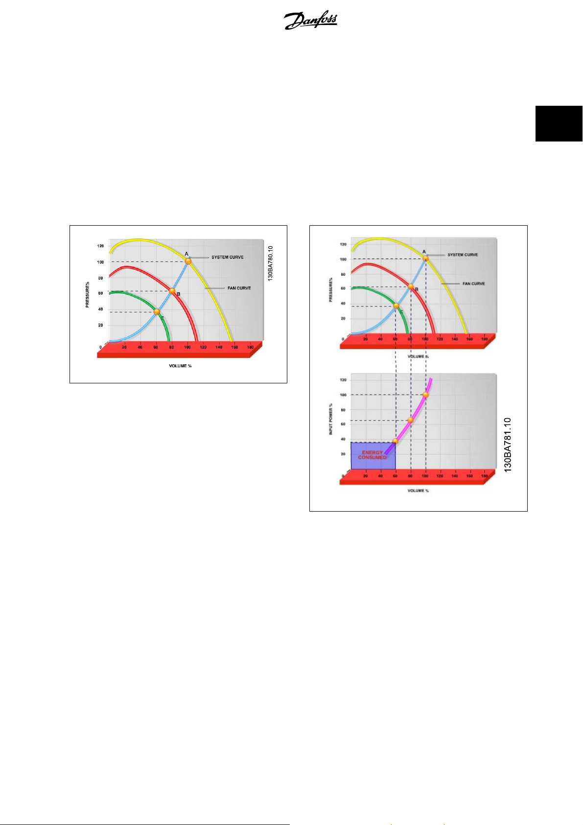
2.6.2. The clear advantage - energy savings
The very clear advantage of using a frequency converter for controlling the speed of fans or pumps lies in the electricity savings.
When comparing with alternative control systems and technologies, a frequency converter is the optimum energy control system for controlling fan and
pump systems.
Illustration 2.1: The graph is showing fan curves (A, B and C) for re-
duced fan volumes.
2
Illustration 2.2: When using a frequency converter to reduce fan ca-
pacity to 60% - more than 50% energy savings may be obtained in
typical applications.
2.6.3. Example of energy savings
As can be seen from the figure (the laws of proportionality), the flow is controlled by changing the rpm. By reducing the speed only 20% from the rated
speed, the flow is also reduced by 20%. This is because the flow is directly proportional to the rpm. The consumption of electricity, however, is reduced
by 50%.
If the system in question only needs to be able to supply a flow that corresponds to 100% a few days in a year, while the average is below 80% of the
rated flow for the remainder of the year, the amount of energy saved is even more than 50%.
MG.11.B7.02 - VLT® is a registered Danfoss trademark
15
Page 16
2
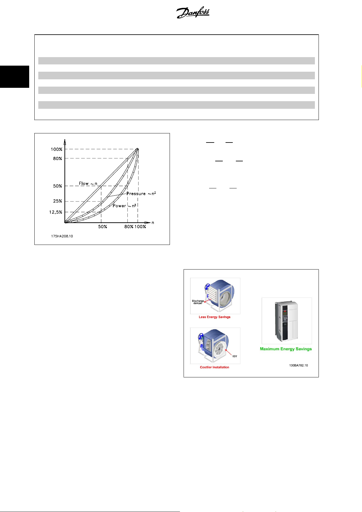
2. Introduction to VLT HVAC Drive VLT® HVAC Drive Design Guide
The laws of proportionality
The figure below describes the dependence of flow, pressure and power consumption on rpm.
Q = Flow P = Power
Q1 = Rated flow P1 = Rated power
Q
= Reduced flow P2 = Reduced power
2
H = Pressure n = Speed regulation
H1 = Rated pressure n1 = Rated speed
H
= Reduced pressure n2 = Reduced speed
2
2.6.4. Comparison of energy savings
The Danfoss frequency converter solution offers major savings compared
with traditional energy saving solutions. This is because the frequency
converter is able to control fan speed according to thermal load on the
system and the fact that the frequency converter has a build-in facility
that enables the frequency converter to function as a Building Manage-
ment System, BMS.
Flow
:
Pressure
Power
Q
Q
:
:
n
1
2
P
P
1
=
n
2
H
H
1
2
n
(
2
1
(
)
n
2
n
3
1
)
n
2
1
=
2
=
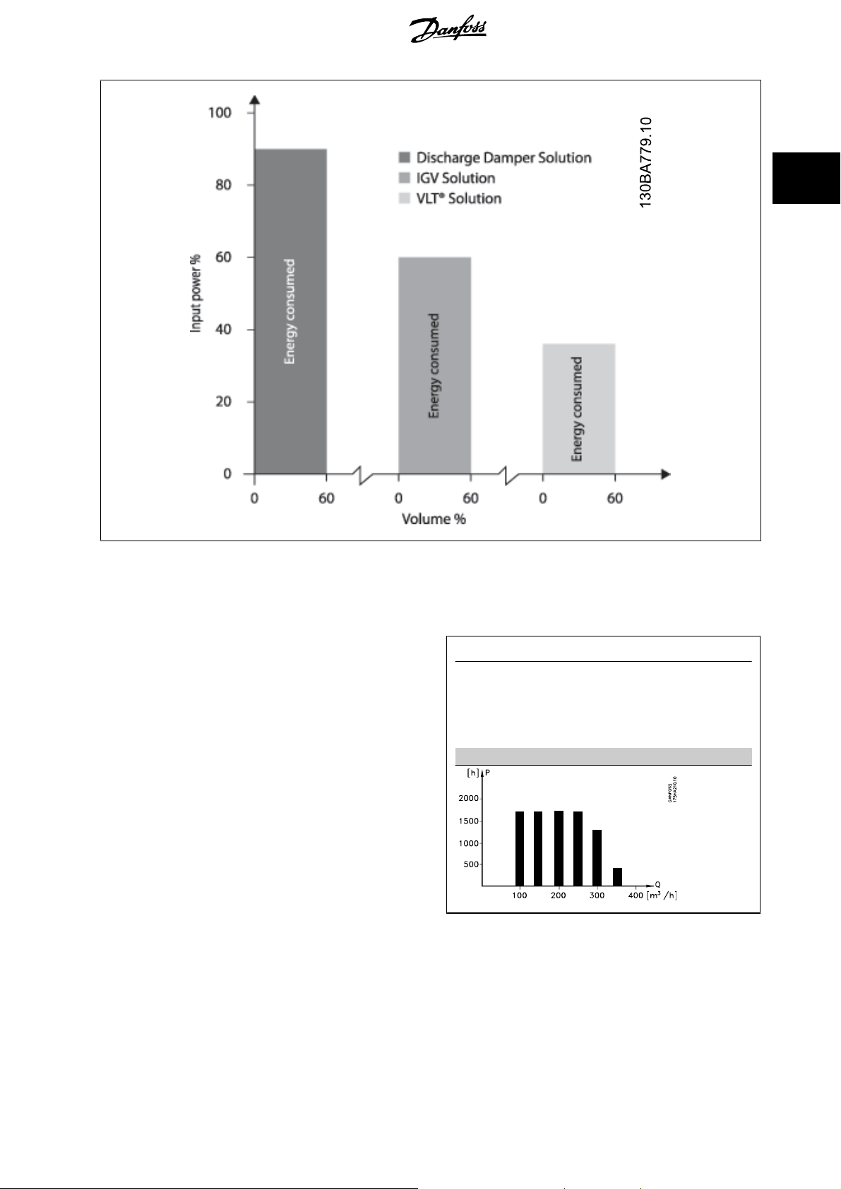
The graph below illustrates typical energy savings obtainable with 3 well-
known solutions when fan volume is reduced to i.e. 60%.
As the graph shows, more than 50% energy savings can be achieved in
typical applications.
16
MG.11.B7.02 - VLT® is a registered Danfoss trademark
Illustration 2.3: The three common energy saving systems.
Page 17
VLT® HVAC Drive Design Guide 2. Introduction to VLT HVAC Drive
2
Illustration 2.4: Discharge dampers reduce power consumption somewhat. Inlet Guide Vans offer a 40% reduction but are expensive to install. The
Danfossfrequency converter solution reduces energy consumption with more than 50% and is easy to install.
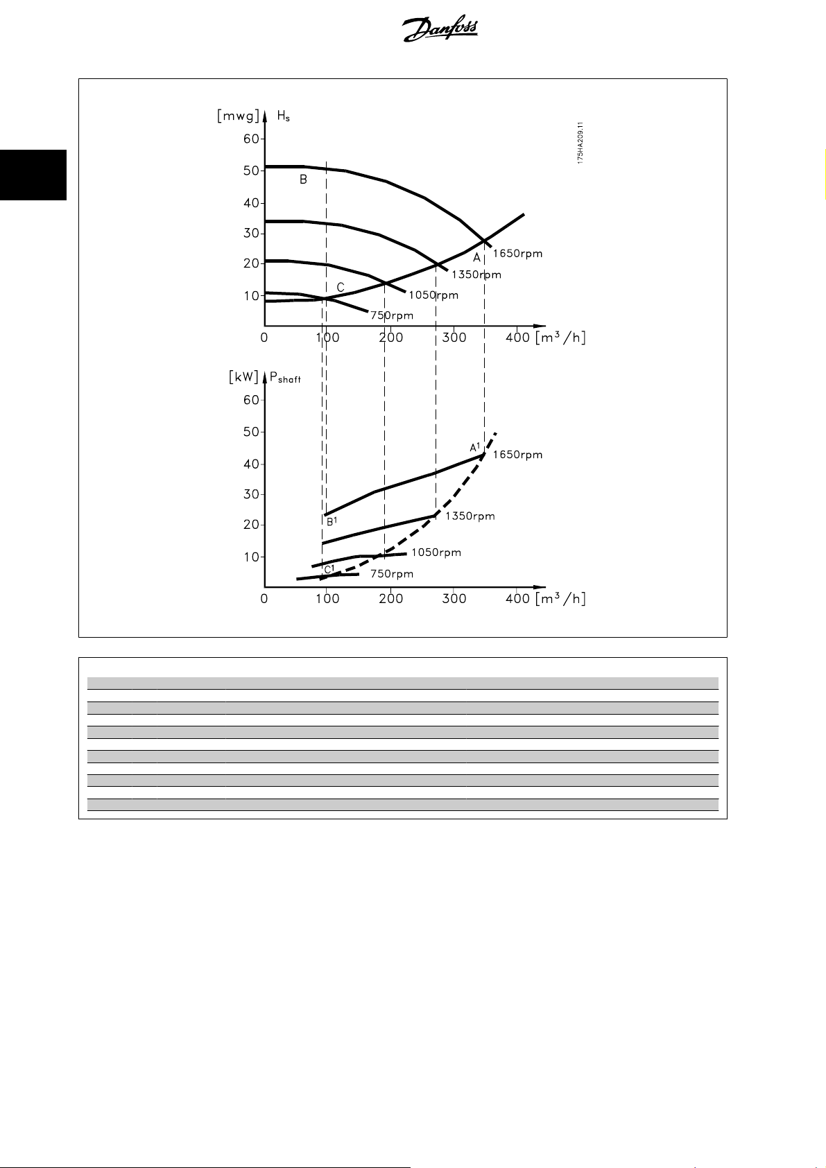
2.6.5. Example with varying flow over 1 year
The example below is calculated on the basis of pump characteristics ob-
tained from a pump datasheet.
The result obtained shows energy savings in excess of 50% at the given
flow distribution over a year. The pay back period depends on the price
per kwh and price of frequency converter. In this example it is less than
a year when compared with valves and constant speed.
Energy savings
P
shaft=Pshaft output
Flow distribution over 1 year
MG.11.B7.02 - VLT® is a registered Danfoss trademark
17
Page 18
2
2. Introduction to VLT HVAC Drive VLT® HVAC Drive Design Guide
m3/h
Distribution Valve regulation Frequency converter control
% Hours Power Consumption Power Consumption
A1 - B
350 5 438 42,5 18.615 42,5 18.615
300 15 1314 38,5 50.589 29,0 38.106
250 20 1752 35,0 61.320 18,5 32.412
200 20 1752 31,5 55.188 11,5 20.148
150 20 1752 28,0 49.056 6,5 11.388
100 20 1752 23,0 40.296 3,5 6.132
Σ 100 8760 275.064 26.801
1
kWh A1 - C
1
2.6.6. Better control
If a frequency converter is used for controlling the flow or pressure of a system, improved control is obtained.
A frequency converter can vary the speed of the fan or pump, thereby obtaining variable control of flow and pressure.
Furthermore, a frequency converter can quickly adapt the speed of the fan or pump to new flow or pressure conditions in the system.
Simple control of process (Flow, Level or Pressure) utilizing the built in PID control.
kWh
18
MG.11.B7.02 - VLT® is a registered Danfoss trademark
Page 19
VLT® HVAC Drive Design Guide 2. Introduction to VLT HVAC Drive
2.6.7. Cos φ compensation
Generally speaking, a frequency converter with a cos φ of 1 provides power factor correction for the cos φ of the motor, which means that there is no
need to make allowance for the cos φ of the motor when sizing the power factor correction unit.
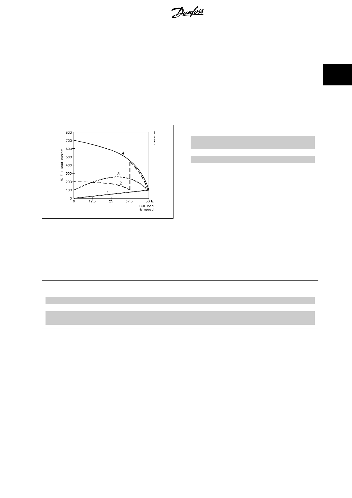
2.6.8. Star/delta starter or soft-starter not required
When larger motors are started, it is necessary in many countries to use equipment that limits the start-up current. In more traditional systems, a star/
delta starter or soft-starter is widely used. Such motor starters are not required if a frequency converter is used.
As illustrated in the figure below, a frequency converter does not consume more than rated current.
1 = VLT HVAC Drive
2 = Star/delta starter
3 = Soft-starter
4 = Start directly on mains
2.6.9. Using a frequency converter saves money
The example on the following page shows that a lot of equipment is not required when a frequency converter is used. It is possible to calculate the cost
of installing the two different systems. In the example on the following page, the two systems can be established at roughly the same price.
2
2.6.10. Without a frequency converter
The figure shows a fan system made in the traditional way.
D.D.C. = Direct Digital Control E.M.S. = Energy Management system
V.A.V. = Variable Air Volume
Sensor P = Pressure Sensor T = Temperature
MG.11.B7.02 - VLT® is a registered Danfoss trademark
19
Page 20
2
2. Introduction to VLT HVAC Drive VLT® HVAC Drive Design Guide
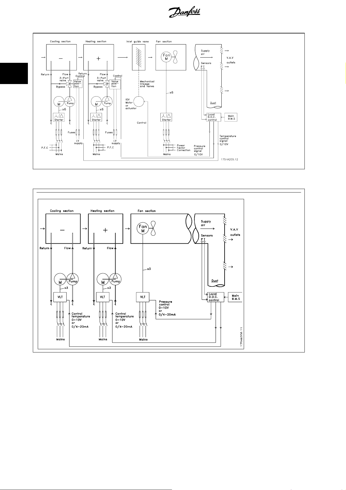
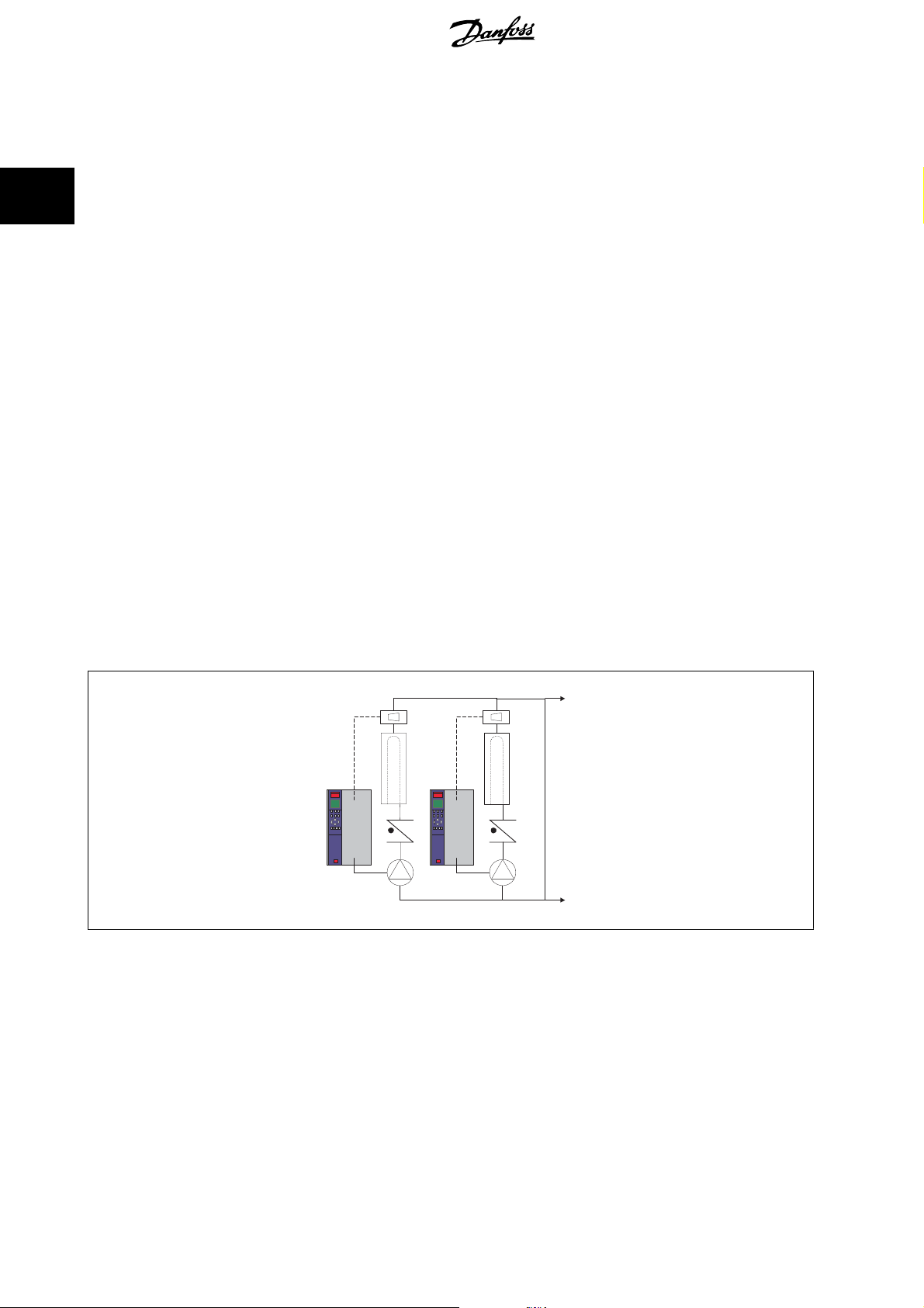
2.6.11. With a frequency converter
The figure shows a fan system controlled by frequency converters.
20
MG.11.B7.02 - VLT® is a registered Danfoss trademark
Page 21

VLT® HVAC Drive Design Guide 2. Introduction to VLT HVAC Drive
2.6.12. Application examples
The next few pages give typical examples of applications within HVAC.
If you would like to receive further information about a given application, please ask your Danfoss supplier for an information sheet that gives a full
description of the application.
Variable Air Volume
Ask for The Drive to...Improving Variable Air Volume Ventilation Systems MN.60.A1.02
Constant Air Volume
Ask for The Drive to...Improving Constant Air Volume Ventilation Systems MN.60.B1.02
Cooling Tower Fan
Ask for The Drive to...Improving fan control on cooling towers MN.60.C1.02
Condenser pumps
Ask for The Drive to...Improving condenser water pumping systems MN.60.F1.02
Primary pumps
Ask for The Drive to...Improve your primary pumping in primay/secondary pumping systems MN.60.D1.02
Secondary pumps
Ask for The Drive to...Improve your secondary pumping in primay/secondary pumping systems MN.60.E1.02
2
MG.11.B7.02 - VLT® is a registered Danfoss trademark
21
Page 22
2
2. Introduction to VLT HVAC Drive VLT® HVAC Drive Design Guide
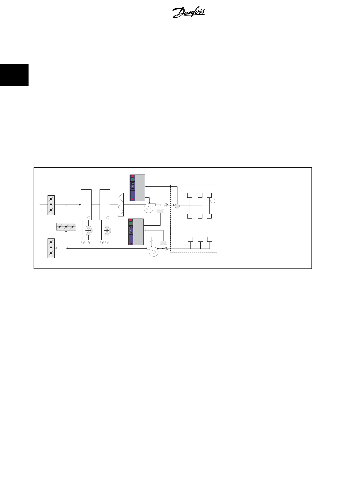
2.6.13. Variable Air Volume
VAV or Variable Air Volume systems, are used to control both the ventilation and temperature to satisfy the requirements of a building. Central VAV
systems are considered to be the most energy efficient method to air condition buildings. By designing central systems instead of distributed systems, a
greater efficiency can be obtained.
The efficiency comes from utilizing larger fans and larger chillers which have much higher efficiencies than small motors and distributed air-cooled chillers.
Savings are also seen from the decreased maintenance requirements.
2.6.14. The VLT solution
While dampers and IGVs work to maintain a constant pressure in the ductwork, a frequency converter solution saves much more energy and reduces
the complexity of the installation. Instead of creating an artificial pressure drop or causing a decrease in fan efficiency, the frequency converter decreases
the speed of the fan to provide the flow and pressure required by the system.
Centrifugal devices such as fans behave according to the centrifugal laws. This means the fans decrease the pressure and flow they produce as their
speed is reduced. Their power consumption is thereby significantly reduced.
The return fan is frequently controlled to maintain a fixed difference in airflow between the supply and return. The advanced PID controller of the HVAC
frequency converter can be used to eliminate the need for additional controllers.
Pressure
Cooling coil
D1
D2
Heating coil
Filter
signal
Supply fan
3
Flow
Pressure
transmitter
VAV boxes
T
Return fan
D3
Flow
3
22
MG.11.B7.02 - VLT® is a registered Danfoss trademark
Page 23
VLT® HVAC Drive Design Guide 2. Introduction to VLT HVAC Drive
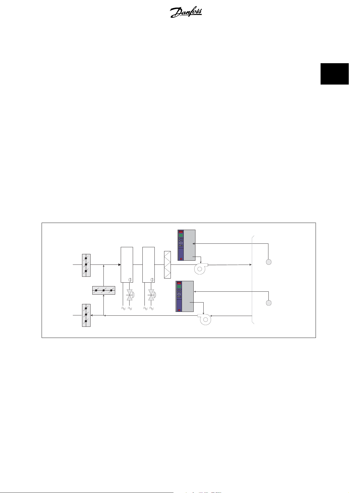
2.6.15. Constant Air Volume
CAV, or Constant Air Volume systems are central ventilation systems usually used to supply large common zones with the minimum amounts of fresh
tempered air. They preceded VAV systems and therefore are found in older multi-zoned commercial buildings as well. These systems preheat amounts
of fresh air utilizing Air Handling Units (AHUs) with a heating coil, and many are also used to air condition buildings and have a cooling coil. Fan coil units
are frequently used to assist in the heating and cooling requirements in the individual zones.
2.6.16. The VLT solution
2
With a frequency converter, significant energy savings can be obtained while maintaining decent control of the building. Temperature sensors or CO
sensors can be used as feedback signals to frequency converters. Whether controlling temperature, air quality, or both, a CAV system can be controlled
to operate based on actual building conditions. As the number of people in the controlled area decreases, the need for fresh air decreases. The CO
sensor detects lower levels and decreases the supply fans speed. The return fan modulates to maintain a static pressure setpoint or fixed difference
between the supply and return air flows.
With temperature control, especially used in air conditioning systems, as the outside temperature varies as well as the number of people in the controlled
zone changes, different cooling requirements exist. As the temperature decreases below the set-point, the supply fan can decrease its speed. The return
fan modulates to maintain a static pressure set-point. By decreasing the air flow, energy used to heat or cool the fresh air is also reduced, adding further
savings.
Several features of the Danfoss HVAC dedicated frequency converter can be utilized to improve the performance of your CAV system. One concern of
controlling a ventilation system is poor air quality. The programmable minimum frequency can be set to maintain a minimum amount of supply air
regardless of the feedback or reference signal. The frequency converter also includes a 3-zone, 3 setpoint PID controller which allows monitoring both
temperature and air quality. Even if the temperature requirement is satisfied, the frequency converter will maintain enough supply air to satisfy the air
quality sensor. The controller is capable of monitoring and comparing two feedback signals to control the return fan by maintaining a fixed differential
air flow between the supply and return ducts as well.
Temperature
Cooling coil
D1
Heating coil
Filter
signal
Supply fan
Temperature
transmitter
2
2
D2
D3
Pressure
signal
Return fan
Pressure
transmitter
MG.11.B7.02 - VLT® is a registered Danfoss trademark
23
Page 24
2
2. Introduction to VLT HVAC Drive VLT® HVAC Drive Design Guide
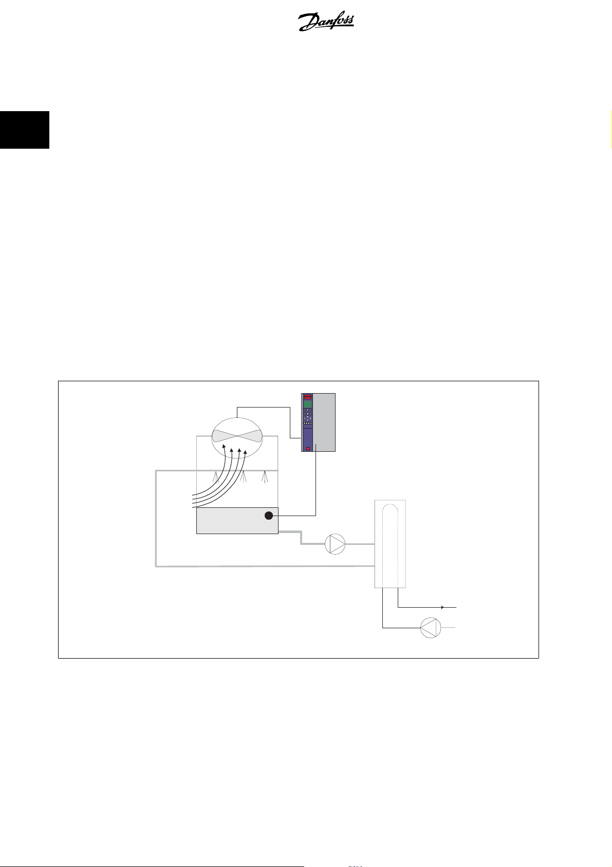
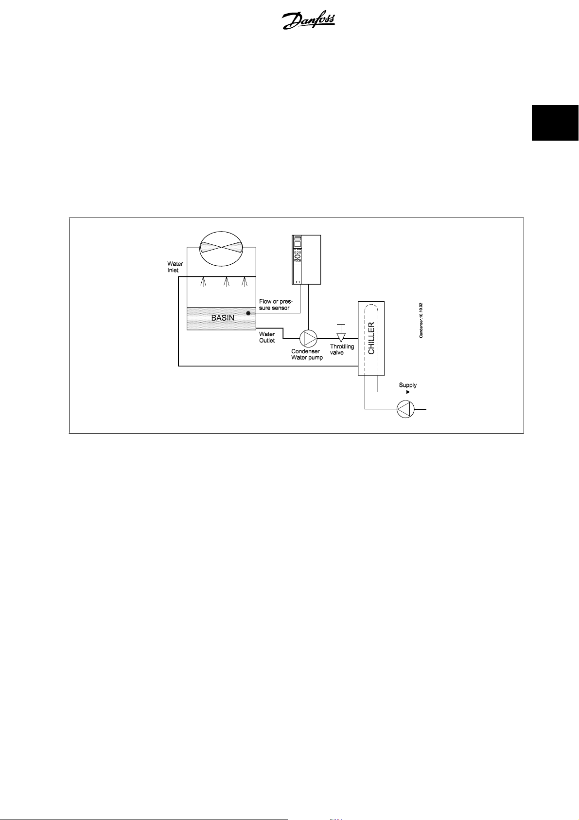
2.6.17. Cooling Tower Fan
Cooling Tower Fans are used to cool condenser water in water cooled chiller systems. Water cooled chillers provide the most efficient means of creating
chilled water. They are as much as 20% more efficient than air cooled chillers. Depending on climate, cooling towers are often the most energy efficient
method of cooling the condenser water from chillers.
They cool the condenser water by evaporation.
The condenser water is sprayed into the cooling tower onto the cooling towers “fill” to increase its surface area. The tower fan blows air through the fill
and sprayed water to aid in the evaporation. Evaporation removes energy from the water dropping its temperature. The cooled water collects in the
cooling towers basin where it is pumped back into the chillers condenser and the cycle is repeated.
2.6.18. The VLT solution
With a frequency converter, the cooling towers fans can be controlled to the required speed to maintain the condenser water temperature. The frequency
converters can also be used to turn the fan on and off as needed.
Several features of the Danfoss HVAC dedicated frequency converter, the HVAC frequency converter can be utilized to improve the performance of your
cooling tower fans application. As the cooling tower fans drop below a certain speed, the effect the fan has on cooling the water becomes small. Also,
when utilizing a gear-box to frequency control the tower fan, a minimum speed of 40-50% may be required.
The customer programmable minimum frequency setting is available to maintain this minimum frequency even as the feedback or speed reference calls
for lower speeds.
Also as a standard feature, you can program the frequency converter to enter a “sleep” mode and stop the fan until a higher speed is required. Additionally,
some cooling tower fans have undesireable frequencies that may cause vibrations. These frequencies can easily be avoided by programming the bypass
frequency ranges in the frequency converter.
Water Inlet
Temperature
Sensor
BASIN
Water Outlet
Conderser
Water pump
CHILLER
Supply
24
MG.11.B7.02 - VLT® is a registered Danfoss trademark
Page 25
VLT® HVAC Drive Design Guide 2. Introduction to VLT HVAC Drive
2.6.19. Condenser pumps
Condenser Water pumps are primarily used to circulate water through the condenser section of water cooled chillers and their associated cooling tower.
The condenser water absorbs the heat from the chiller's condenser section and releases it into the atmosphere in the cooling tower. These systems are
used to provide the most efficient means of creating chilled water, they are as much as 20% more efficient than air cooled chillers.
2.6.20. The VLT solution
Frequency converters can be added to condenser water pumps instead of balancing the pumps with a throttling valve or trimming the pump impeller.
Using a frequency converter instead of a throttling valve simply saves the energy that would have been absorbed by the valve. This can amount to savings
of 15-20% or more. Trimming the pump impeller is irreversible, thus if the conditions change and higher flow is required the impeller must be replaced.
2
MG.11.B7.02 - VLT® is a registered Danfoss trademark
25
Page 26
2
2. Introduction to VLT HVAC Drive VLT® HVAC Drive Design Guide
2.6.21. Primary pumps
Primary pumps in a primary/secondary pumping system can be used to maintain a constant flow through devices that encounter operation or control
difficulties when exposed to variable flow. The primary/ secondary pumping technique decouples the “primary” production loop from the “secondary”
distribution loop. This allows devices such as chillers to obtain constant design flow and operate properly while allowing the rest of the system to vary in
flow.
As the evaporator flow rate decreases in a chiller, the chilled water begins to become over-chilled. As this happens, the chiller attempts to decrease its
cooling capacity. If the flow rate drops far enough, or too quickly, the chiller cannot shed its load sufficiently and the chiller’s low evaporator tempera-
ture safety trips the chiller requiring a manual reset. This situation is common in large installations especially when two or more chillers in parallel are
installed if primary/ secondary pumping is not utilized.
2.6.22. The VLT solution
Depending on the size of the system and the size of the primary loop, the energy consumption of the primary loop can become substantial.
A frequency converter can be added to the primary system, to replace the throttling valve and/or trimming of the impellers, leading to reduced operating
expenses. Two control methods are common:
The first method uses a flow meter. Because the desired flow rate is known and is constant, a flow meter installed at the discharge of each chiller, can
be used to control the pump directly. Using the built-in PID controller, the frequency converter will always maintain the appropriate flow rate, even
compensating for the changing resistance in the primary piping loop as chillers and their pumps are staged on and off.
The other method is local speed determination. The operator simply decreases the output frequency until the design flow rate is achieved.
Using a frequency converter to decrease the pump speed is very similar to trimming the pump impeller, except it doesn’t require any labor and the pump
efficiency remains higher. The balancing contractor simply decreases the speed of the pump until the proper flow rate is achieved and leaves the speed
fixed. The pump will operate at this speed any time the chiller is staged on. Because the primary loop doesn’t have control valves or other devices that
can cause the system curve to change and the variance due to staging pumps and chillers on and off is usually small, this fixed speed will remain
appropriate. In the event the flow rate needs to be increased later in the systems life, the frequency converter can simply increase the pump speed
instead of requiring a new pump impeller.
Flowmeter
F
CHILLER
Flowmeter
F
CHILLER
26
MG.11.B7.02 - VLT® is a registered Danfoss trademark
Page 27
VLT® HVAC Drive Design Guide 2. Introduction to VLT HVAC Drive
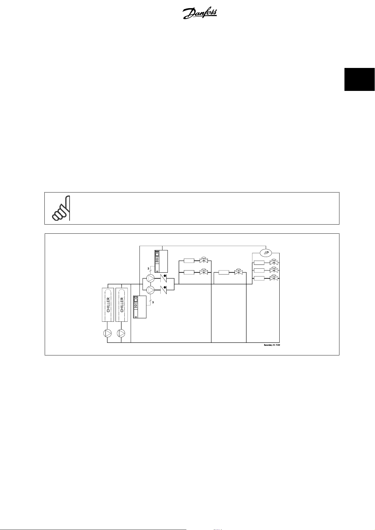
2.6.23. Secondary pumps
Secondary pumps in a primary/secondary chilled water pumping system are used to distribute the chilled water to the loads from the primary production
loop. The primary/secondary pumping system is used to hydronically de-couple one piping loop from another. In this case. The primary pump is used to
maintain a constant flow through the chillers while allowing the secondary pumps to vary in flow, increase control and save energy.
If the primary/secondary design concept is not used and a variable volume system is designed, when the flow rate drops far enough or too quickly, the
chiller cannot shed its load properly. The chiller’s low evaporator temperature safety then trips the chiller requiring a manual reset. This situation is
common in large installations especially when two or more chillers in parallel are installed.
2.6.24. The VLT solution
While the primary-secondary system with two-way valves improves energy savings and eases system control problems, the true energy savings and
control potential is realized by adding frequency converters.
With the proper sensor location, the addition of frequency converters allows the pumps to vary their speed to follow the system curve instead of the
pump curve.
This results in the elimination of wasted energy and eliminates most of the over-pressurization, two-way valves can be subjected too.
As the monitored loads are reached, the two-way valves close down. This increases the differential pressure measured across the load and two-way
va lv e. A s t his di ffe re ntia l p res su re sta rt s to r is e , the p um p is slowed to maintain the control head also called setpoint value. This set-point value is calculated
by summing the pressure drop of the load and two way valve together under design conditions.
2
NB!
Please note that when running multiple pumps in parallel, they must run at the same speed to maximize energy savings, either with
individual dedicated drives or one frequency converter running multiple pumps in parallel.
MG.11.B7.02 - VLT® is a registered Danfoss trademark
27
Page 28
2. Introduction to VLT HVAC Drive VLT® HVAC Drive Design Guide
2.7. VLT HVAC Drive Controls
2.7.1. Control Principle
2
A frequency converter rectifies AC voltage from mains into DC voltage, after which this DC voltage is converted into a AC current with a variable amplitude
and frequency.
The motor is supplied with variable voltage / current and frequency, which enables infinitely variable speed control of three-phased, standard AC motors.
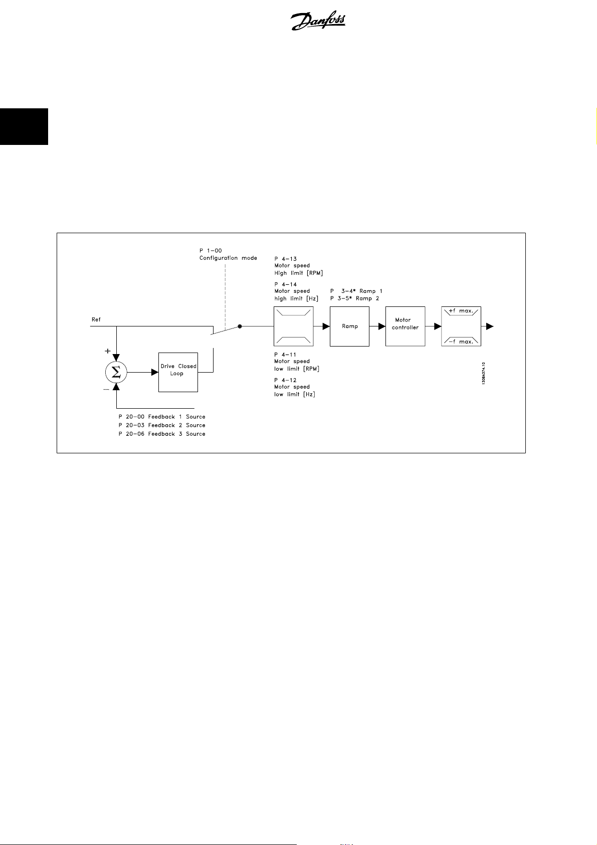
2.7.2. Control Structure
Control structure in open loop and closed loop configurations:
In the configuration shown in the illustration above, par. 1-00 is set to
received and fed through the ramp limitation and speed limitation before being sent to the motor control. The output of the motor control is then limited
by the maximum frequency limit.
Closed loop
Select
parameters are located in par. group 20-**.
[3] in par. 1-00 to use the PID controller for closed loop control of e.g. flow, level or pressure in the controlled application. The PID
Open loop
[0]. The resulting reference from the reference handling system is
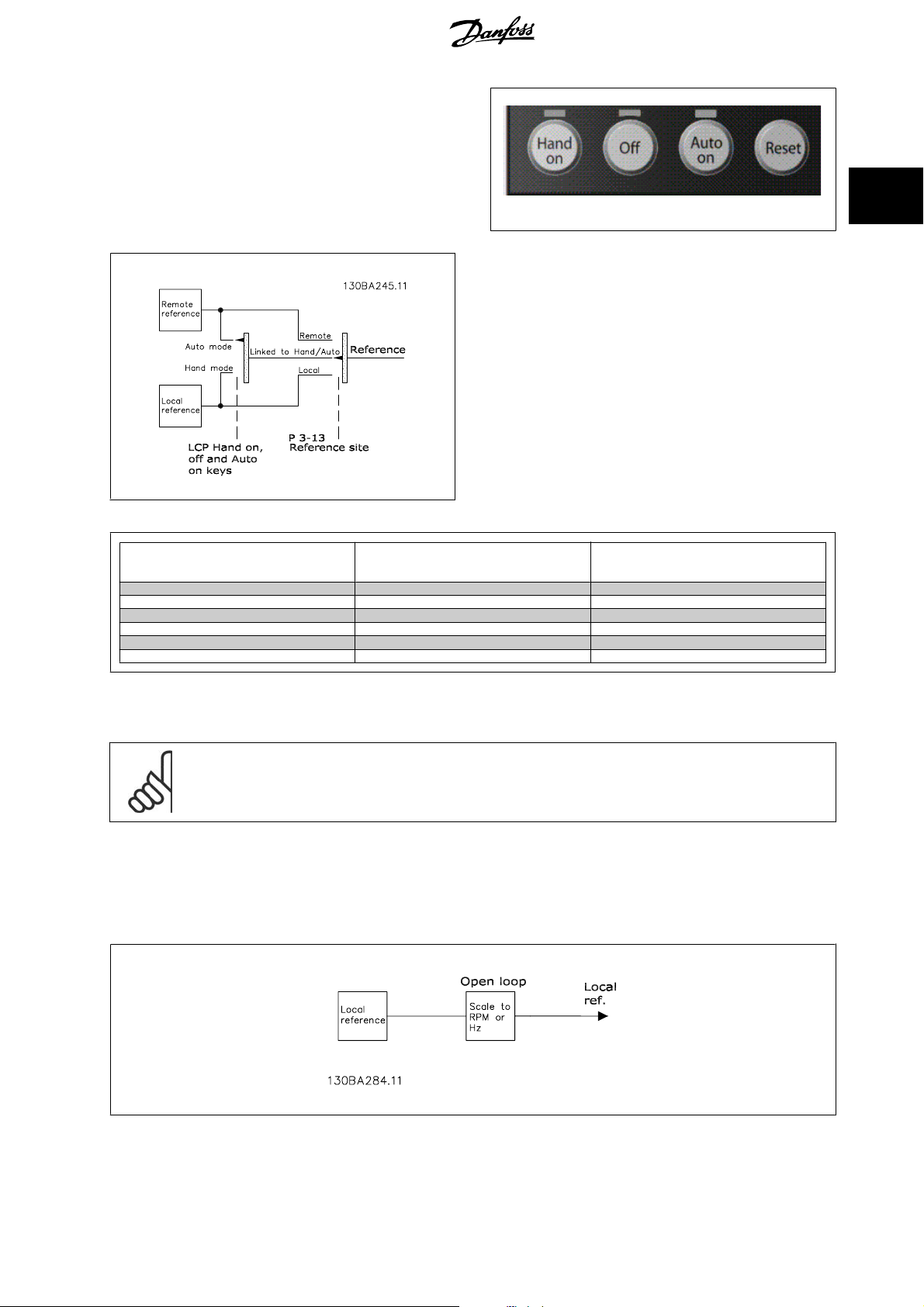
2.7.3. Local (Hand On) and Remote (Auto On) Control
The frequency converter can be operated manually via the local control panel (LCP) or remotely via analog and digital inputs and serial bus.
If allowed in par. 0-40, 0-41, 0-42, and 0-43, it is possible to start and stop the frequency converter via the LCP using the [Hand ON] and [Off] keys.
Alarms can be reset via the [RESET] key. After pressing the [Hand On] key, the frequency converter goes into Hand Mode and follows (as default) the
Local reference set by using the LCP arrow keys.
28
MG.11.B7.02 - VLT® is a registered Danfoss trademark
Page 29
0
VLT® HVAC Drive Design Guide 2. Introduction to VLT HVAC Drive
After pressing the [Auto On] key, the frequency converter goes into Auto
mode and follows (as default) the Remote reference. In this mode, it is
possible to control the frequency converter via the digital inputs and var-
ious serial interfaces (RS-485, USB, or an optional fieldbus). See more
about starting, stopping, changing ramps and parameter set-ups etc. in
par. group 5-1* (digital inputs) or par. group 8-5* (serial communica-
tion).
130BP046.1
Active Reference and Configuration Mode
The active reference can be either the local reference or the remote ref-
erence.
2
In par. 3-13
lected by selecting
To permanently select the remote reference select
lecting
on which mode is active. (Hand Mode or Auto Mode).
Hand Off
Auto
LCP Keys
Hand Linked to Hand / Auto Local
Hand -> Off Linked to Hand / Auto Local
Auto Linked to Hand / Auto Remote
Auto -> Off Linked to Hand / Auto Remote
All keys Local Local
All keys Remote Remote
The table shows under which conditions either the Local reference or the Remote reference is active. One of them is always active, but both can not be
active at the same time.
NB!
Local Ref. will be restored at power-down.
Reference Site
Par. 3-13
Reference Site
Linked to Hand/Auto
the local reference can be permanently se-
Local
[2].
Remote
[0] (default) the reference site will depend
Active Reference
[1]. By se-
Par. 1-00
is active (see table above for the conditions).
Reference Handling - Local Reference
Configuration Mode
determines what kind of application control principle (i.e. Open Loop or Closed loop) is used when the Remote reference
MG.11.B7.02 - VLT® is a registered Danfoss trademark
29
Page 30
2. Introduction to VLT HVAC Drive VLT® HVAC Drive Design Guide
2.8. PID
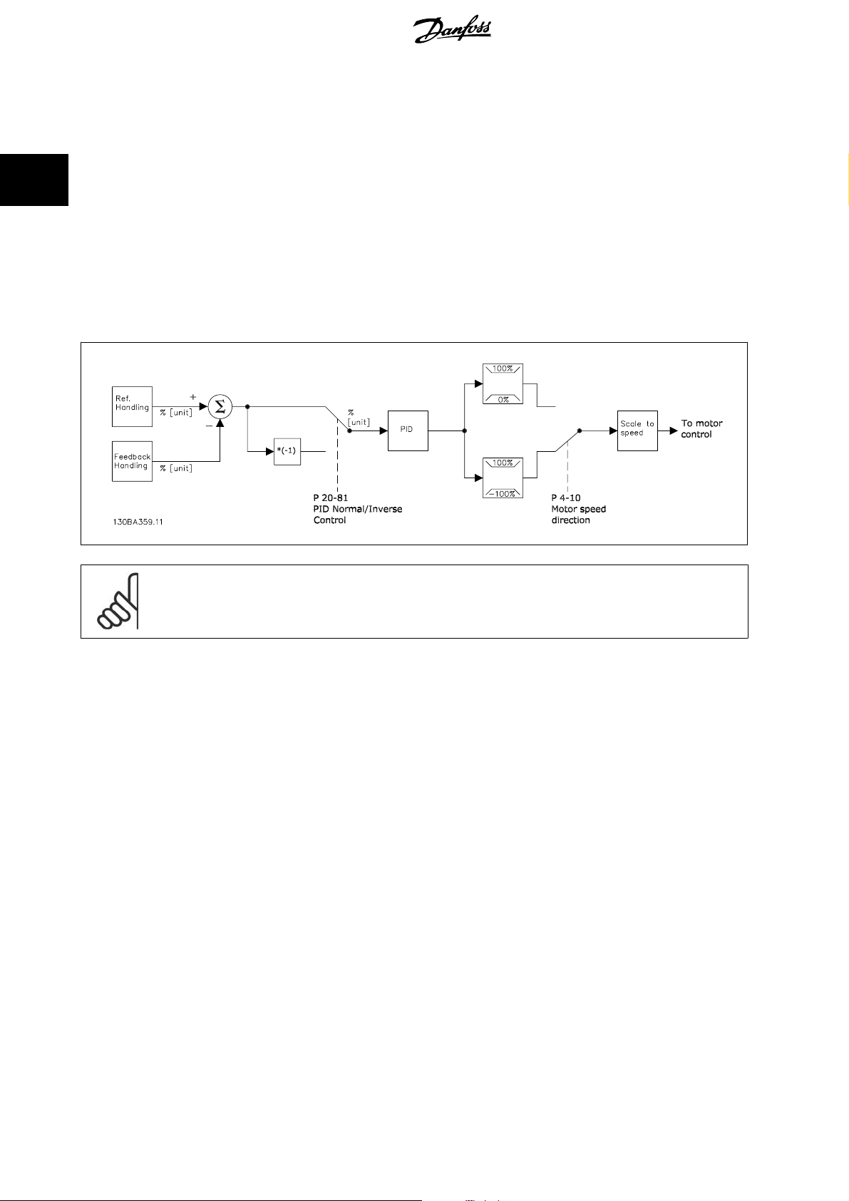
2.8.1. Closed Loop (PID) Controller
2
The frequency converter’s Closed Loop Controller allows the frequency converter to become an integral part of the controlled system. The frequency
converter receives a feedback signal from a sensor in the system. It then compares this feedback to a setpoint reference value and determines the error,
if any, between these two signals. It then adjusts the speed of the motor to correct this error.
For example, consider a ventilation system where the speed of the supply fan is to be controlled so that the static pressure in the duct is constant. The
desired static pressure value is supplied to the frequency converter as the setpoint reference. A static pressure sensor measures the actual static pressure
in the duct and supplies this to the frequency converter as a feedback signal. If the feedback signal is greater than the setpoint reference, the frequency
converter will slow down to reduce the pressure. In a similar way, if the duct pressure is lower than the setpoint reference, the frequency converter will
automatically speed up to increase the pressure provided by the fan.
NB!
While the default values for the frequency converter’s Closed Loop Controller will often provide satisfactory performance, the control
of the system can often be optimized by adjusting some of the Closed Loop Controller’s parameters.
The figure is a block diagram of the frequency converter’s Closed Loop Controller. The details of the Reference Handling block and Feedback Handling
block are described in their respective sections below.
The following parameters are relevant for a simple PID control application:
30
MG.11.B7.02 - VLT® is a registered Danfoss trademark
Page 31

VLT® HVAC Drive Design Guide 2. Introduction to VLT HVAC Drive
Parameter Description of function
Feedback 1 Source par. 20-00 Select the source for Feed back 1 . This is most commonl y an analog inpu t, but other sources are
also available. Use the scaling of this input to provide the appropriate values for this signal. By
default, Analog Input 54 is the default source for Feedback 1.
Reference/Feedback Unit par 20-12 Select the unit for the setpoint referenceand feedback for the frequency converter’s Closed Loop
Controller. Note: Because a conversion can be applied to the feedback signal before it is used
by the Closed Loop Controller, the Reference/Feedback Unit (par. 20-12) may not be the same
as the Feedback Source Unit (par. 20-02, 20-05 and 20-08).
PID Normal/Inverse Control par. 20-81 Select
PID Proportional Gain par. 20-93 This parameter adjusts the output of the frequency converter’s closed loop controlled based on
PID Integral Time par. 20-94 The integrator adds over time (integrates) the error between the feedback and the setpoint
This table summarizes the parameters that are needed to set up the frequency converter’s Closed Loop Controller when a single feedback signal with no
conversion is compared to a single setpoint. This is the most common type of Closed Loop Controller.
Normal
[0] if the motor’s speed should decrease when the feedback is greater than the
Inverse
setpoint reference. Select
is greater than the setpoint reference.
the error between the feedback and the setpoint reference. Quick controller response is obtained
when this value is large. However, if too large of a value is used, the frequency converter’s output
frequency may become unstable.
reference. This is required to ensure that the error approaches zero. Quick controller response
is obtained when this value is small. However, if too small of a value is used, the frequency
converter’s output frequency may become unstable. A setting of 10000 s disables the integrator.
[1] if the motor’s speed should increase when the feedback
2
2.8.2. Closed Loop Control Relevant Parameters
The frequency converter’s Closed Loop Controller is capable of handling more complex applications, such as situations where a conversion function is
applied to the feedback signal or situations where multiple feedback signals and/or setpoint references are used. The below table summarizes the
additional parameters than may be useful in such applications.
Parameter
Feedback 2 Source
Feedback 3 Source
Feedback 1 Conversion
Feedback 2 Conversion
Feedback 3 Conversion
Feedback 1 Source Unit
Feedback 2 Source Unit
Feedback 3 Source Unit
Feedback Function par. 20-20 When multiple feedbacks or setpoints are used, this determines how they will be pro-
Setpoint 1
Setpoint 2
Setpoint 3
Refrigerant par. 20-30 If any Feedback Conversion (par. 20-01, 20-04 or 20-07) is set to
par. 20-03
par. 20-06
par. 20-01
par. 20-04
par. 20-07
par. 20-02
par. 20-05
par. 20-08
par. 20-21
par. 20-22
par. 20-23
Description of function
Select the source, if any, for Feedback 2 or 3. This is most commonly a frequency con-
verter analog input, but other sources are also available. Par. 20-20 determines how
multiple feedback signals will be processed by the frequency converter’s Closed Loop
Controller. By default, these are set to
These are used to convert the feedback signal from one type to another, for example
from pressure to flow or from pressure to temperature (for compressor applications).
If
Pressure to temperature
Group 20-3*, Feedback Adv. Conv. By default, these are set to
Select the unit for a feedback source, prior to any conversions. This is used for display
purposes only. This parameter is only available when using
feedback conversion.
cessed by the frequency converter’s Closed Loop Controller.
These setpoints can be used to provide a setpoint reference to the frequency converter’s
Closed Loop Controller. Par. 20-20 determines how multiple setpoint references will be
processed. Any other references that are activated in par. group 3-1* will add to these
values.
[2] is selected, the refrigerant must be specified in par.
No function
[0].
Linear
Pressure to Temperature
[0].
Pressure to Temper-
ature
[2], the refrigerant type must be selected here. If the refrigerant used is not listed
here, select
20-31, 20-32 and 20-33.
User defined
[7] and specify the characteristics of the refrigerant in par.
MG.11.B7.02 - VLT® is a registered Danfoss trademark
31
Page 32

2
2. Introduction to VLT HVAC Drive VLT® HVAC Drive Design Guide
Parameter Description of function
Custom Refrigerant A1
Custom Refrigerant A2
Custom Refrigerant A3
PID Start Speed [RPM]
PID Start Speed [Hz]
On Reference Bandwidth par. 20-84 This determines how close the feedback must be to the setpoint reference for the fre-
PID Anti Windup par. 20-91
PID Differentiation Time par. 20-95 This controls the output of the frequency converter’s Closed Loop Controller based on
PID Diff. Gain Limit par. 20-96 Because the differentiator responds to the rate of change of the feedback, a rapid
Lowpass Filter Time :
Analog Input 53
Analog Input 54
Digital (pulse) input 29
Digital (pulse) input 33
par. 20-31
par. 20-32
par. 20-33
par. 20-82
par. 20-83
par. 6-16
par. 6-26
par. 5-54
par. 5-59
When par. 20-30 is set to
value of coefficients A1, A2 and A3 in the conversion equation:
Temperature
The parameter that is visible will depend on the setting of par. 0-02, Motor Speed Unit.
In some applications, after a start command it is important to quickly ramp the motor
up to some pre-determined speed before activating the frequency converter’s Closed
Loop Controller. This parameter defines that starting speed.
quency converter to indicate that the feedback is equal to the setpoint.
On
[1] effectively disables the Closed Loop Controller’s integral function when it is not
possible to adjust the output frequency of the frequency converter to correct the error.
This allows the controller to respond more quickly once it can again control the system.
Off
[0] disables this function, making the integral function stay active continuously.
the rate of change of feedback. While this can provide fast controller response, such
response is seldom needed in HVAC systems. The default value for this parameter is
Off, or 0.00 s.
change can cause a large, undesired change in the output of the controller. This is used
to limit the maximum effect of the differentiator. This is not active when par. 20-95 is
set to Off.
This is used to filter out high frequency noise from the feedback signal. The value en-
tered here is the time constant for the low pass filter. The cut-off frequency in Hz can
be calculated as follows:
F
cut
Variations in the feedback signal whose frequency is below F
frequency converter’s Closed Loop Controller, while variations at a higher frequency are
considered to be noise and will be attenuated. Large values of Lowpass Filter Time will
provide more filtering, but may cause the controller to not respond to actual variations
in the feedback signal.
=
−
off
=
(
ln(pressure
T
2π
lowpass
User defined
1
[7], these parameters are used to define the
A
2
+1)−A1
−
A
3
)
will be used by the
cut-off
2.8.3. Example of Closed Loop PID Control
The following is an example of a Closed Loop Control for a ventilation system:
32
MG.11.B7.02 - VLT® is a registered Danfoss trademark
Page 33

VLT® HVAC Drive Design Guide 2. Introduction to VLT HVAC Drive
In a ventilation system, the temperature is to be maintained at a constant
value. The desired temperature is set between -5 and +35°C using a 0-10
volt potentiometer. Because this is a cooling application, if the tempera-
ture is above the setpoint value, the speed of the fan must be increased
1. Start/Stop via switch connected between terminals 12 (+24 V) and 18.
2. Temperature reference via a potentiometer (-5 to +35°C, 0 10 V)
connected to terminals 50 (+10 V), 53 (input) and 55 (common).
3. Temperature feedback via transmitter (-10-40°C, 4-20 mA) connected
to terminal 54. Switch S202 behind the Local Control Panel set to ON
(current input).
to provide more cooling air flow. The temperature sensor has a range of
-10 to +40°C and uses a two-wire transmitter to provide a 4-20 mA signal.
The output frequency range of the frequency converter is 10 to 50 Hz.
2
MG.11.B7.02 - VLT® is a registered Danfoss trademark
33
Page 34

2
2. Introduction to VLT HVAC Drive VLT® HVAC Drive Design Guide
2.8.4. Programming Order
Function Par. no. Setting
1) Make sure the motor runs properly. Do the following:
Set the frequency converter to control the motor
based on frequency converter output frequency.
Set the motor parameters using nameplate data. 1-2* As specified by motor name plate
Run Automatic Motor Adaptation. 1-29
2) Check that the motor is running in the right direction.
Pressing [Hand On] starts the motor at 5Hz in forward
direction and the display shows: “Motor is running.
Check if motor rotation direction is correct.
3) Make sure the frequency converter limits are set to safe values
Check that the ramp settings are within capabilities
of the frequency converter and allowed application
operating specifications.
Prohibit the motor from reversing (if necessary) 4-10
Set acceptable limits for the motor speed. 4-12
Switch from open loop to closed loop. 1-00
4) Configure the feedback to the PID controller.
Set up Analog Input 54 as a feedback input. 20-00
Select the appropriate reference/feedback unit. 20-12
5) Configure the setpoint reference for the PID controller.
Set acceptable limits for the setpoint reference.
Set up Analog Input 53 as Reference 1 Source. 3-15
6) Scale the analog inputs used for setpoint reference and feedback.
Scale Analog Input 53 for the temperature range of
the potentiometer (-5 to +35°C, 0-10 V).
Scale Analog Input 54 for the temperature range of
the temperature sensor (-10 to +40°C, 4-20 mA)
7) Tune the PID controller parameters.
Select inverse control because motor’s speed should
increase when the feedback is greater than the setpoint reference.
Adjust the frequency converter’s Closed Loop Controller, if needed.
8) Finished!
Save the parameter setting to the LCP for safe keeping
0-02
If motor rotation direction is incorrect, two motor
3-41
3-42
4-14
4-19
3-02
3-03
6-10
6-11
6-14
6-15
6-22
6-23
6-24
6-25
20-81
20-93
20-94
0-50
Hz
[1]
Enable complete AMA
function.
phase cables should be interchanged.
60 sec.
60 sec.
Depends on motor/load size!
Also active in Hand mode.
Clockwise
10 Hz
50 Hz
50 Hz
Closed Loop
[0]
[3]
Analog input 54
°C
[60]
-5 °C
35 °C
Analog input 53
0 V
10 V (default)
-5 °C
35 °C
4 mA
20 mA (default)
-10 °C
40 °C
Inverse
[1]
See Optimization of the PID Controller, below.
All to LCP
[1]
[1] and then run the AMA
[2] (default)
[1] (default)
34
MG.11.B7.02 - VLT® is a registered Danfoss trademark
Page 35

VLT® HVAC Drive Design Guide 2. Introduction to VLT HVAC Drive
2.8.5. Tuning the Drive's Closed Loop Controller
Once the frequency converter’s Closed Loop Controller has been set up, the performance of the controller should be tested. In many cases, its performance
may be acceptable using the default values of PID Proportional Gain (par. 20-93) and PID Integral Time (par. 20-94). However, in some cases it may be
helpful to optimize these parameter values to provide faster system response while still controlling speed overshoot. In many situations, this can be done
by following the procedure below.
1. Start the motor
2. Set par. 20-93 (PID Proportional Gain) to 0.3 and increase it until the feedback signal begins to oscillate. If necessary, start and stop the frequency
converter or make step changes in the setpoint reference to attempt to cause oscillation. Next reduce the PID Proportional Gain until the feedback
signal stabilizes. Then reduce the proportional gain by 40-60%.
3. Set par. 20-94 (PID Integral Time) to 20 sec. and reduce it until the feedback signal begins to oscillate. If necessary, start and stop the frequency
converter or make step changes in the setpoint reference to attempt to cause oscillation. Next, increase the PID Integral Time until the feedback
signal stabilizes. Then increase of the Integral Time by 15-50%.
4. Par. 20-95 (PID Differentiation Time) should only be used for very fast-acting systems. The typical value is 25% of the PID Integral Time (par.
20-94). The differentiator should only be used when the setting of the proportional gain and the integral time has been fully optimized. Make
sure that oscillations of the feedback signal are sufficiently dampened by the lowpass filter for the feedback signal (par 6 16, 6 26, 5 54 or 5 59,
as required).
2.8.6. Ziegler Nichols Tuning Method
2
In general, the above procedure is sufficient for HVAC applications. However, other, more sophisticated procedures can also be used. The Ziegler Nichols
tuning method is a technique which was developed in the 1940s, but is still commonly used today. It generally provides acceptable control performance
using a simple experiment and parameter calculation.
NB!
This method must not be used on applications that could be damaged by oscillations created by marginally stable control settings.
2. Increase the value of the PID Proportional Gain (par 20-93) until
the point of instability is reached, as indicated by sustained os-
cillations of the feedback signal. The PID Proportional Gain that
Illustration 2.5: Marginally stable system
1. Select proportional control only. That is, PID Integral Time (par.
20-94) is set to Off (10000 s) and PID Differentiation Time (par.
20 95) is also set to Off (0 s, in this case).
causes sustained oscillations is called the critical gain, K
3. Measure the period of oscillation, P
NOTE: P
should be measured when the amplitude of oscillation
u
is relatively small. The output must not saturate (i.e., the max-
imum or minimum feedback signal must not be reached during
the test).
4. Use the table below to calculate the necessary PID control pa-
rameters.
.
u
.
u
Type of Control Proportional Gain Integral Time Differentiation Time
PI-control 0.45 *
PID tight control 0.6 *
PID some overshoot 0.33 *
Ziegler Nichols tuning for regulator, based on a stability boundary
Experience has shown that the control setting according to Ziegler Nichols rule provides a good closed loop response for many systems. If necessary,
the operator can do the final tuning of the control iteratively to modify the response of the control loop.
K
u
K
u
K
u
MG.11.B7.02 - VLT® is a registered Danfoss trademark
0.833 *
0.5 *
P
0.5 *
P
P
u
u
u
-
0.125 *
0.33 *
P
u
P
u
35
Page 36

2
2. Introduction to VLT HVAC Drive VLT® HVAC Drive Design Guide
2.8.7. Reference Handling
A block diagram of how the drive produces the Remote Reference is shown below.
36
MG.11.B7.02 - VLT® is a registered Danfoss trademark
Page 37

VLT® HVAC Drive Design Guide 2. Introduction to VLT HVAC Drive
The Remote Reference is comprised of:
• Preset references.
• External references (analog inputs, pulse frequency inputs, digital potentiometer inputs and serial communication bus references).
• The Preset relative reference.
•Feedback controlled setpoint.
Up to 8 preset references can be programmed in the drive. The active preset reference can be selected using digital inputs or the serial communications
bus. The reference can also be supplied externally, most commonly from an analog input. This external source is selected by one of the 3 Reference
Source parameters (par. 3-15, 3-16 and 3-17). Digipot is a digital potentiometer. This is also commonly called a Speed Up/Speed Down Control or a
Floating Point Control. To set it up, one digital input is programmed to increase the reference while another digital input is programmed to decrease the
reference. A third digital input can be used to reset the Digipot reference. All reference resources and the bus reference are added to produce the total
External Reference. The External Reference, the Preset Reference or the sum of the two can be selected to be the active reference. Finally, this reference
can by be scaled using the Preset Relative Reference (par. 3-14).
The scaled reference is calculated as follows:
Reference=X+X
Where X is the external reference, the preset reference or the sum of these and Y is the Preset Relative Reference (par. 3-14) in [%].
Y
×
(
)
100
2
NB!
If Y, the Preset Relative Reference (par. 3-14) is set to 0%, the reference will not be affected by the scaling
2.8.8. Feedback Handling
A block diagram of how the frequency converter processes the feedback signal is shown below.
Feedback handling can be configured to work with applications requiring advanced control, such as multiple setpoints and multiple feedbacks. Three
types of control are common.
Single Zone, Single Setpoint
Single Zone Single Setpoint is a basic configuration. Setpoint 1 is added to any other reference (if any, see Reference Handling) and the feedback signal
is selected using par. 20-20.
MG.11.B7.02 - VLT® is a registered Danfoss trademark
37
Page 38

2
2. Introduction to VLT HVAC Drive VLT® HVAC Drive Design Guide
Multi Zone, Single Setpoint
Multi Zone Single Setpoint uses two or three feedback sensors but only one setpoint. The feedbacks can be added, subtracted (only feedback 1 and 2)
or averaged. In addition, the maximum or minimum value may be used. Setpoint 1 is used exclusively in this configuration.
Multi Zone Multi Setpoint
applies an individual setpoint reference to each feedback. The frequency converter’s Closed Loop Controller chooses one pair to control the frequency
converter based on the user’s selection in par. 20-20. If
the frequency converter’s speed. (Note that a negative value is always smaller than a positive value).
Multi Setpoint Max
[14] is selected, the setpoint/feedback pair with the smallest difference controls
Multi Setpoint Min
If
Maximum
[14] attempts to keep all zones at or below their respective setpoints, while
respective setpoints.
Example:
A two zone two setpoints application Zone 1 setpoint is 18°C and the feedback is 19°C. Zone 2 setpoint is 22°C and the feedback is 20°C. If
[14] is selected, Zone 1’s setpoint and feedback are sent to the PID controller, since this has the smaller difference (feedback is higher than setpoint,
Max
resulting in a negative difference). If
larger difference (feedback is lower than setpoint, resulting in a positive difference).
[13] is selected, the setpoint/feedback pair with the largest difference controls the speed of the frequency converter.
Multi Setpoint Min
Multi Setpoint Min
[13] is selected, Zone 2’s setpoint and feedback is sent to the PID controller, since this has the
[13] attempts to keep all zones at or above their
Multi Setpoint
Multi Setpoint
2.8.9. Feedback Conversion
In some applications it may be useful to convert the feedback signal. One example of this is using a pressure signal to provide flow feedback. Since the
square root of pressure is proportional to flow, the square root of the pressure signal yields a value proportional to the flow. This is shown below.
Another application that may benefit from feedback conversion is compressor control. In such applications the output of a pressure sensor may be
converted to the refrigerant temperature using the equation:
A
Temperature
where A1, A2 and A3 are refrigerant-specific constants.
=
(
ln(pressure
2
+1)−A1
38
−
A
3
)
MG.11.B7.02 - VLT® is a registered Danfoss trademark
Page 39

VLT® HVAC Drive Design Guide 2. Introduction to VLT HVAC Drive
2.9. General aspects of EMC
2.9.1. General Aspects of EMC Emissions
Electrical interference is usually conducted at frequences in the range 150 kHz to 30 MHz. Airborne interference from the drive system in the range 30
MHz to 1 GHz is generated from the inverter, motor cable, and the motor.
As shown in the illustration below, capacitive currents in the motor cable coupled with a high dV/dt from the motor voltage generate leakage currents.
The use of a screened motor cable increases the leakage current (see illustration below) because screened cables have higher capacitance to earth than
unscreened cables. If the leakage current is not filtered, it will cause greater interference on the mains in the radio frequency range below approx. 5
MHz. Since the leakage current (I
from the screened motor cable according to the below figure.
The screen reduces the radiated interference but increases the low-frequency interference on the mains. The motor cable screen must be connected to
the frequency converter enclosure as well as on the motor enclosure. This is best done by using integrated screen clamps so as to avoid twisted screen
ends (pigtails). These increase the screen impedance at higher frequencies, which reduces the screen effect and increases the leakage current (I
If a screened cable is used for Fieldbus, relay, control cable, signal interface and brake, the screen must be mounted on the enclosure at both ends. In
some situations, however, it will be necessary to break the screen to avoid current loops.
) is carried back to the unit through the screen (I 3), there will in principle only be a small electro-magnetic field (I4)
1
).
4
2
If the screen is to be placed on a mounting plate for the frequency converter, the mounting plate must be made of metal, because the screen currents
have to be conveyed back to the unit. Moreover, ensure good electrical contact from the mounting plate through the mounting screws to the frequency
converter chassis.
NB!
When unscreened cables are used, some emission requirements are not complied with, although the immunity requirements are ob-
served.
In order to reduce the interference level from the entire system (unit + installation), make motor and brake cables as short as possible. Avoid placing
cables with a sensitive signal level alongside motor and brake cables. Radio interference higher than 50 MHz (airborne) is especially generated by the
control electronics.
2.9.2. Emission Requirements
According to the EMC product standard for adjustable speed frequency converters EN/IEC61800-3:2004 the EMC requirements depend on the intended
use of the frequency converter. Four categories are defined in the EMC product standard. The definitions of the four categories together with the
requirements for mains line conducted emissions are given in the table below:
MG.11.B7.02 - VLT® is a registered Danfoss trademark
39
Page 40

2. Introduction to VLT HVAC Drive VLT® HVAC Drive Design Guide
2
Category
C1 frequency converters installed in the first environment (home and office) with a supply
C2 frequency converters installed in the first environment (home and office) with a supply
C3 frequency converters installed in the second environment (industrial) with a supply
C4 frequency converters installed in the second environment with a supply voltage above
When the generic emission standards are used the frequency converters are required to comply with the following limits:
Environment
First environment
(home and office)
Second environment
(industrial environment)
Definition Conducted emission requirement accord-
ing to the limits given in EN55011
voltage less than 1000 V.
voltage less than 1000 V which are neither plug-in nor movable and are intended to be
installed and commissioned by a professional.
voltage lower than 1000 V.
1000 V and rated current above 400 A or intended for use in complex systems.
Generic standard Conducted emission requirement accord-
EN/IEC61000-6-3 Emission standard for residential, commercial and
light industrial environments.
EN/IEC61000-6-4 Emission standard for industrial environments. Class A Group 1
An EMC plan should be made.
ing to the limits given in EN55011
2.9.3. EMC Test Results (Emission)
Class B
Class A Group 1
Class A Group 2
No limit line.
Class B
The following test results have been obtained using a system with a frequency converter (with options if relevant),
a screened control cable, a control box with potentiometer, as well as a motor and motor screened cable.
RFI filter type Conducted emission.
Radiated emission
Maximum shielded cable length.
Industrial environment Housing,
trades and
Industrial envi-
ronment
Housing, trades and
light industries
light industries
Setup EN 55011
Class A2
EN 55011
Class A1
EN 55011
Class B
EN 55011 ClassA1EN 55011 Class B
H1
1.1-45 kW 200-240 V
150 m 150 m 50 m Yes No
1.1-90 kW 380-480 V 150 m 150 m 50 m Yes No
H2
1.1-3.7 kW 200-240 V
5 m No No No No
5.5-45 kW 200-240 V 25 m No No No No
1.1-7.5 kW 380-480 V
11-90 kW 380-480 V
110-450 kW 380-480 V
75-500 kW 525-600 V
5 m No No No No
25 m No No No No
50 m No No No No
150 m No No No No
H3
1.1-45 kW 200-240 V
75 m 50 m 10 m Yes No
1.1-90 kW 380-480 V 75 m 50 m 10 m Yes No
H4
110-450 kW 380-480 V
150 m 150 m No Yes No
75-315 kW 525-600 V 150 m 30 m No No No
Hx
1.1-90 kW 525-600 V
- - - - -
Table 2.1: EMC Test Results (Emission)
40
MG.11.B7.02 - VLT® is a registered Danfoss trademark
Page 41

VLT® HVAC Drive Design Guide 2. Introduction to VLT HVAC Drive
2.9.4. Immunity Requirements
The immunity requirements for frequency converters depend on the environment where they are installed. The requirements for the industrial environment
are higher than the requirements for the home and office environment. All Danfoss frequency converters comply with the requirements for the industrial
environment and consequently comply also with the lower requirements for home and office environment with a large safety margin.
In order to document immunity against electrical interference from electrical phenomena, the following immunity tests have been made on a system
consisting of a frequency converter (with options if relevant), a screened control cable and a control box with potentiometer, motor cable and motor.
The tests were performed in accordance with the following basic standards:
• EN 61000-4-2 (IEC 61000-4-2): Electrostatic discharges (ESD): Simulation of electrostatic discharges from human beings.
• EN 61000-4-3 (IEC 61000-4-3): Incoming electromagnetic field radiation, amplitude modulated simulation of the effects of radar and radio
communication equipment as well as mobile communications equipment.
• EN 61000-4-4 (IEC 61000-4-4): Burst transients: Simulation of interference brought about by switching a contactor, relay or similar devices.
• EN 61000-4-5 (IEC 61000-4-5): Surge transients: Simulation of transients brought about e.g. by lightning that strikes near installations.
• EN 61000-4-6 (IEC 61000-4-6): RF Common mode: Simulation of the effect from radio-transmission equipment joined by connection cables.
See following EMC immunity form.
Voltage range: 200-240 V, 380-480 V
Basic standard Burst
IEC 61000-4-4
Surge
IEC 61000-4-5
ESD
IEC
61000-4-2
Radiated electromagnetic
field
IEC 61000-4-3
RF common
mode voltage
IEC 61000-4-6
Acceptance criterion B B B A A
Line
Motor
4 kV CM
4 kV CM
Brake 4 kV CM
Load sharing 4 kV CM
Control wires
2 kV CM
Standard bus 2 kV CM
Relay wires 2 kV CM
Application and Fieldbus
2 kV CM
options
LCP cable
External 24 V DC
Enclosure
2 kV CM
2 kV CM
— —
2 kV/2 Ω DM
4 kV/12 Ω CM
4 kV/2 Ω
4 kV/2 Ω
4 kV/2 Ω
1)
1)
2 kV/2 Ω
2 kV/2 Ω
2 kV/2 Ω
2 kV/2 Ω
2 kV/2 Ω
0.5 kV/2 Ω DM
1 kV/12 Ω CM
— —
1)
— —
— —
1)
1)
1)
1)
1)
— —
— —
— —
— —
— —
— —
— —
8 kV AD
6 kV CD
10 V/m —
10 V
10 V
10 V
10 V
10 V
10 V
10 V
10 V
10 V
10 V
RMS
RMS
RMS
RMS
RMS
RMS
RMS
RMS
RMS
RMS
AD: Air Discharge
CD: Contact Discharge
CM: Common mode
DM: Differential mode
1. Injection on cable shield.
2
Table 2.2: Immunity
2.10. Galvanic isolation (PELV)
2.10.1. PELV - Protective Extra Low Voltage
PELV offers protection by way of extra low voltage. Protection against electric shock is ensured when the electrical supply is of the PELV type and the
installation is made as described in local/national regulations on PELV supplies.
All control terminals and relay terminals 01-03/04-06 comply with PELV (Protective Extra Low Voltage) (Does not apply to 525-600 V units and at grounded
Delta leg above 300 V).
Galvanic (ensured) isolation is obtained by fulfilling requirements for higher isolation and by providing the relevant creapage/clearance distances. These
requirements are described in the EN 61800-5-1 standard.
MG.11.B7.02 - VLT® is a registered Danfoss trademark
41
Page 42

2. Introduction to VLT HVAC Drive VLT® HVAC Drive Design Guide
The components that make up the electrical isolation, as described below, also comply with the requirements for higher isolation and the relevant test
as described in EN 61800-5-1.
The PELV galvanic isolation can be shown in six locations (see illustration):
In order to maintain PELV all connections made to the control terminals must be PELV, e.g. thermistor must be reinforced/double insulated.
2
1. Power supply (SMPS) incl. signal isolation of U
intermediate current voltage.
2. Gate drive that runs the IGBTs (trigger transformers/opto-cou-
plers).
3. Current transducers.
4. Opto-coupler, brake module.
5. Internal inrush, RFI, and temperature measurement circuits.
6. Custom relays.
The functional galvanic isolation (a and b on drawing) is for the 24 V back-up option and for the RS 485 standard bus interface.
Installation at high altitude
380 - 500 V: At altitudes above 3 km, please contact Danfoss regarding PELV.
525 - 690 V: At altitudes above 2 km, please contact Danfoss regarding PELV.
, indicating the
DC
Illustration 2.6: Galvanic isolation
2.11.1. Earth Leakage Current
Warning:
Touching the electrical parts may be fatal - even after the equipment has been disconnected from mains.
Also make sure that other voltage inputs have been disconnected, such as load-sharing (linkage of DC intermediate circuit), as well as
the motor connection for kinetic back-up.
Before touching any electrical parts, wait at least: Please consult the section
Shorter time than stated in the table is allowed only if indicated on the nameplate for the specific unit.
Safety>Caution
.
Leakage Current
The earth leakage current from the frequency converter exceeds 3.5 mA. To ensure that the earth cable has a good mechanical
connection to the earth connection (terminal 95), the cable cross section must be at least 10 mm
separately.
Residual Current Device
This product can cause a d.c. current in the protective conductor. Where a residual current device (RCD) is used for extra protection,
only an RCD of Type B (time delayed) shall be used on the supply side of this product. See also RCD Application Note MN.90.Gx.yy.
Protective earthing of the frequency converter and the use of RCD's must always follow national and local regulations.
2
or 2 rated earth wires terminated
2.12. Control with brake function
2.12.1. Selection of Brake Resistor
In certain applications, for instance in tunnel or underground railway station ventilation systems, it is desirable to bring the motor to a stop more rapidly
than can be achieved through controlling via ramp down or by free-wheeling. In such applications, dynamic braking with a braking resistor may be utilized.
Using a braking resistor ensures that the energy is absorbed in the resistor and not in the frequency converter.
42
MG.11.B7.02 - VLT® is a registered Danfoss trademark
Page 43

VLT® HVAC Drive Design Guide 2. Introduction to VLT HVAC Drive
If the amount of kinetic energy transferred to the resistor in each braking period is not known, the average power can be calculated on the basis of the
cycle time and braking time also called intermitted duty cycle. The resistor intermittent duty cycle is an indication of the duty cycle at which the resistor
is active. The below figure shows a typical braking cycle.
The intermittent duty cycle for the resistor is calculated as follows:
Duty Cycle = tb / T
T = cycle time in seconds
t
is the braking time in seconds (as part of the total cycle time)
b
Danfoss offers brake resistors with duty cycle of 5%, 10% and 40% suitable for use with the VLT FC102 HVAC frequency converter series. If a 10% duty
cycle resistor is applied, this is able of absorbing braking power upto 10% of the cycle time with the remaining 90% being used to dissipate heat from
the resistor.
2
For further selection advice, please contact Danfoss.
NB!
If a short circuit in the brake transistor occurs, power dissipation in the brake resistor is only prevented by using a mains switch or
contactor to disconnect the mains for the frequency converter. (The contactor can be controlled by the frequency converter).
2.12.2. Brake Resistor Calculation
The brake resistance is calculated as shown:
R
Ω =
br
where
P
= P
peak
As can be seen, the brake resistance depends on the intermediate circuit voltage (UDC).
The brake function of the frequency converter is settled in 3 areas of mains power supply:
Size Brake active Warning before cut out Cut out (trip)
3 x 200-240 V 390 V (UDC) 405 V 410 V
3 x 380-480 V 778 V 810 V 820 V
3 x 525-600 V 943 V 965 V 975 V
motor
2
U
dc
P
peak
x Mbr x η
motor
x η[W]
MG.11.B7.02 - VLT® is a registered Danfoss trademark
43
Page 44

2. Introduction to VLT HVAC Drive VLT® HVAC Drive Design Guide
NB!
Check that the brake resistor can cope with a voltage of 410 V, 820 V or 975 V - unless Danfoss brake resistors are used.
2
Danfoss recommends the brake resistance R
) of 110%. The formula can be written as:
(%)
η
is typically at 0.90 η is typically at 0.98
motor
For 200 V, 480 V and 600 V frequency converters, R
200V:
480V:
600
1) For frequency converters ≤ 7.5 kW shaft output
2) For frequency converters > 7.5 kW shaft output
V:R
R
rec
R
rec
rec
107780
=
P
motor
375300
=
P
motor
630137
=
P
motor
NB!
The resistor brake circuit resistance selected sho ul d n ot be higher t ha n t ha t recommended by Danfoss. If a brake resistor with a higher
ohmic value is selected, the braking torque may not be achieved because there is a risk that the frequency converter cuts out for safety
reasons.
Ω
Ω
Ω
, i.e. one that guarantees that the frequency converter is able to brake at the highest braking torque (M
rec
R
rec
at 160% braking torque is written as:
rec
)
1
480
V:R
Ω =
rec
P
motor
=
xM
428914
P
motor
br
2
U
x
100
dc
xηx
br
(%)
Ω
)
2
η
motor
NB!
If a short circuit in the brake transistor occurs, power dissipation in the brake resistor is only prevented by using a mains switch or
contactor to disconnect the mains for the frequency converter. (The contactor can be controlled by the frequency converter).
NB!
Do not touch the brake resistor as it can get very hot while/after braking.
2.12.3. Control with Brake Function
The brake is to limit the voltage in the intermediate circuit when the motor acts as a generator. This occurs, for example, when the load drives the motor
and the power accumulates on the DC link. The brake is built up as a chopper circuit with the connection of an external brake resistor.
Placing the brake resistor externally offers the following advantages:
- The brake resistor can be selected on the basis of the application in question.
- The brake energy can be dissipated outside the control panel, i.e. where the energy can be utilized.
- The electronics of the frequency converter will not be overheated if the brake resistor is overloaded.
The brake is protected against short-circuiting of the brake resistor, and the brake transistor is monitored to ensure that short-circuiting of the transistor
is detected. A relay/digital output can be used for protecting the brake resistor against overloading in connection with a fault in the frequency converter.
In addition, the brake makes it possible to read out the momentary power and the mean power for the latest 120 seconds. The brake can also monitor
the power energizing and make sure it does not exceed a limit selected in par. 2-12. In par. 2-13, select the function to carry out when the power
transmitted to the brake resistor exceeds the limit set in par. 2-12.
44
MG.11.B7.02 - VLT® is a registered Danfoss trademark
Page 45

VLT® HVAC Drive Design Guide 2. Introduction to VLT HVAC Drive
NB!
Monitoring the brake power is not a safety function; a thermal switch is required for that purpose. The brake resistor circuit is not earth
leakage protected.
Over voltage control (OVC)
The function ensures that a trip can be avoided if the DC link voltage increases. This is done by increasing the output frequency to limit the voltage from
the DC link. It is a very useful function, e.g. if the ramp-down time is too short since tripping of the frequency converter is avoided. In this situation the
ramp-down time is extended.
(exclusive brake resistor) can be selected as an alternative brake function in par. 2-17. This function is active for all units.
2.12.4. Brake Resistor Cabling
EMC (twisted cables/shielding)
To reduce the electrical noise from the wires between the brake resistor and the frequency converter, the wires must be twisted.
For enhanced EMC performance a metal screen can be used.
2.13. Extreme running conditions
Short Circuit (Motor Phase – Phase)
The frequency converter is protected against short circuits by means of current measurement in each of the three motor phases or in the DC link. A short
circuit between two output phases will cause an overcurrent in the inverter. The inverter will be turned off individually when the short circuit current
exceeds the permitted value (Alarm 16 Trip Lock).
To protect the frequency converter against a short circuit at the load sharing and brake outputs please see the design guidelines.
Switching on the Output
Switching on the output between the motor and the frequency converter is fully permitted. You cannot damage the frequency converter in any way by
switching on the output. However, fault messages may appear.
2
Motor-generated Over-voltage
The voltage in the intermediate circuit is increased when the motor acts as a generator. This occurs in following cases:
1. The load drives the motor (at constant output frequency from the frequency converter), ie. the load generates energy.
2. During deceleration ("ramp-down") if the moment of inertia is high, the friction is low and the ramp-down time is too short for the energy to be
dissipated as a loss in the frequency converter, the motor and the installation.
3. Incorrect slip compensation setting may cause higher DC link voltage.
The control unit may attempt to correct the ramp if possible (par. 2-17
The inverter turns off to protect the transistors and the intermediate circuit capacitors when a certain voltage level is reached.
See par. 2-10 and par. 2-17 to select the method used for controlling the intermediate circuit voltage level.
Mains Drop-out
During a mains drop-out, the frequency converter keeps running until the intermediate circuit voltage drops below the minimum stop level, which is
typically 15% below the frequency converter's lowest rated supply voltage.
The mains voltage before the drop-out and the motor load determines how long it takes for the inverter to coast.
plus
Static Overload in VVC
When the frequency converter is overloaded (the torque limit in par. 4-16/4-17 is reached), the controls reduces the output frequency to reduce the load.
If the overload is excessive, a current may occur that makes the frequency converter cut out after approx. 5-10 s.
Operation within the torque limit is limited in time (0-60 s) in par. 14-25.
mode
Over-voltage Control)
.
MG.11.B7.02 - VLT® is a registered Danfoss trademark
45
Page 46

2
2. Introduction to VLT HVAC Drive VLT® HVAC Drive Design Guide
2.13.1. Motor Thermal Protection
This is the way Danfoss is protecting the motor from being overheated. It is an electronic feature that simulates a bimetal relay based on internal
measurements. The characteristic is shown in the following figure:
Illustration 2.7: The X-axis is showing the ratio between I
and trips the drive. The curves are showing the characteristic nominal speed at twice the nominal speed and at 0,2x the nominal speed.
It is clear that at lower speed the ETR cuts of at lower heat due to less cooling of the motor. In that way the motor are protected from being over heated
even at low speed. The ETR feature is calculating the motor temperature based on actual current and speed. The calculated temperature is visible as a
read out parameter in par. 16-18 in the frequency converter.
motor
and I
nominal. The Y- axis is showing the time in seconds before the ETR cuts off
motor
The thermistor cut-out value is > 3 kΩ.
Integrate a thermistor (PTC sensor) in the motor for winding protection.
Motor protection can be implemented using a range of techniques: PTC
sensor in motor windings; mechanical thermal switch (Klixon type); or
Electronic Thermal Relay (ETR).
46
MG.11.B7.02 - VLT® is a registered Danfoss trademark
Page 47

VLT® HVAC Drive Design Guide 2. Introduction to VLT HVAC Drive
Using a digital input and 24 V as power supply:
Example: The frequency converter trips when the motor temperature is
too high.
Parameter set-up:
Set par. 1-90 Motor
Set par. 1-93 Thermistor
Thermal Protection
Source
to
Digital Input 33
to
Thermistor Trip
[2]
[6]
2
Using a digital input and 10 V as power supply:
Example: The frequency converter trips when the motor temperature is
too high.
Parameter set-up:
Set par. 1-90 Motor
Set par. 1-93 Thermistor
Thermal Protection
Source
to
to
Digital Input 33
Thermistor Trip
[6]
[2]
Using an analog input and 10 V as power supply:
Example: The frequency converter trips when the motor temperature is
too high.
Parameter set-up:
Set par. 1-90 Motor
Set par. 1-93 Thermistor
Do not select a reference source.
Input
Digital/analog
Digital 24 V < 6.6 kΩ - > 10.8 kΩ
Digital 10 V < 800Ω - > 2.7 kΩ
Analog 10 V < 3.0 kΩ - > 3.0 kΩ
Summary
With the Torque limit feature the motor is protected for being overloaded independent of the speed. With the ETR the motor is protected for being over
heated and there is no need for any further motor protection. That means when the motor is heated up the ETR timer controls for how long time the
motor can be running at the high temperature before it is stopped in order to prevent over heating. If the motor is overloaded without reaching the
temperature where the ETR shuts of the motor, the torque limit is protecting the motor and application for being overloaded.
Thermal Protection
Source
NB!
Check that the chosen supply voltage follows the specification of the used thermistor element.
to
to
Analog Input 54
Supply Voltage
Volt
Thermistor Trip
[2]
[2]
Threshold
Cut-out Values
NB!
ETR is activated in par. 1-90
in par. 14-25.
Torque Limit
and is controlled in par. 4-16. The time before the torque limit warning trips the frequency converter is set
MG.11.B7.02 - VLT® is a registered Danfoss trademark
47
Page 48

2. Introduction to VLT HVAC Drive VLT® HVAC Drive Design Guide
2.14. Safe Stop
2.14.1. Safe Stop
2
The frequency converter can perform the safety function
60204-1).
It is designed and approved suitable for the requirements of Safety Category 3 in EN 954-1. This functionality is called Safe Stop. Prior to integration and
use of Safe Stop in an installation, a thorough risk analysis on the installation must be carried out in order to determine whether the Safe Stop functionality
and safety category are appropriate and sufficient. In order to install and use the Safe Stop function in accordance with the requirements of Safety
Category 3 in EN 954-1, the related information and instructions of the relevant Design Guide must be followed! The information and instructions of the
Operating Instructions are not sufficient for a correct and safe use of the Safe Stop functionality!
Safe Torque Off
(As defined by draft CD IEC 61800-5-2) or
Stop Category 0
(as defined in EN
Illustration 2.8: Diagram showing all electrical terminals. (Terminal 37 present for units with Safe Stop Function only.)
48
MG.11.B7.02 - VLT® is a registered Danfoss trademark
Page 49

VLT® HVAC Drive Design Guide 2. Introduction to VLT HVAC Drive
2
2.14.2. Safe Stop Installation
To carry out an installation of a Category 0 Stop (EN60204) in conformity with Safety Category 3 (EN954-1), follow these instructions:
1. The bridge (jumper) between Terminal 37 and 24 V DC must be removed. Cutting or breaking the jumper is not sufficient. Remove it entirely
to avoid short-circuiting. See jumper on illustration.
2. Connect terminal 37 to 24 V DC by a short-circuit protected cable. The 24 V DC voltage supply must be interruptible by an EN954-1 Category 3
circuit interrupt device. If the interrupt device and the frequency converter are placed in the same installation panel, you can use an unscreened
cable instead of a screened one.
MG.11.B7.02 - VLT® is a registered Danfoss trademark
49
Page 50

2
2. Introduction to VLT HVAC Drive VLT® HVAC Drive Design Guide
Illustration 2.9: Bridge jumper between terminal 37 and 24 VDC
The illustration below shows a Stopping Category 0 (EN 60204-1) with safety Category 3 (EN 954-1). The circuit interrupt is caused by an opening door
contact. The illustration also shows how to connect a non-safety related hardware coast.
Illustration 2.10: Illustration of the essential aspects of an installation to achieve a Stopping Category 0 (EN 60204-1) with safety Category 3 (EN
954-1).
50
MG.11.B7.02 - VLT® is a registered Danfoss trademark
Page 51

VLT® HVAC Drive Design Guide 3. VLT HVAC Drive Selection
3. VLT HVAC Drive Selection
3.1. Options and Accessories
Danfoss offers a wide range of options and accessories for the frequency converters.
3.1.1. Mounting of Option Modules in Slot B
The power to the frequency converter must be disconnected.
For A2 and A3 enclosures:
• Remove the LCP (Local Control Panel), the terminal cover, and the LCP frame from the frequency converter.
• Fit the MCB10x option card into slot B.
• Connect the control cables and relieve the cable by the enclosed cable strips.
Remove the knock out in the extended LCP frame delivered in the option set, so that the option will fit under the extended LCP frame.
• Fit the extended LCP frame and terminal cover.
• Fit the LCP or blind cover in the extended LCP frame.
• Connect power to the frequency converter.
• Set up the input/output functions in the corresponding parameters, as mentioned in the section
For B1, B2, C1 and C2 enclosures:
• Remove the LCP and the LCP cradle
• Fit the MCB 10x option card into slot B
• Connect the control cables and relieve the cable by the enclosed
cable strips
• Fit the cradle
•Fit the LCP
General Technical Data
3
.
A2, A3 and B3 enclosures A5, B1, B2, B4, C1, C2, C3 and C4 enclosures
MG.11.B7.02 - VLT® is a registered Danfoss trademark
51
Page 52

3
3. VLT HVAC Drive Selection VLT® HVAC Drive Design Guide
3.1.2. General Purpose Input Output Module MCB 101
MCB 101 is used for extension of the number of digital and analog inputs
and outputs of the frequency converter.
Contents: MCB 101 must be fitted into slot B in the frequency converter.
• MCB 101 option module
•Extended LCP frame
• Terminal cover
Galvanic Isolation in the MCB 101
Digital/analog inputs are galvanically isolated from other inputs/outputs on the MCB 101 and in the control card of the frequency converter. Digital/analog
outputs in the MCB 101 are galvanically isolated from other inputs/outputs on the MCB 101, but not from these on the control card of the frequency
converter.
If the digital inputs 7, 8 or 9 are to be switched by use of the internal 24 V power supply (terminal 9) the connection between terminal 1 and 5 which is
illustrated in the drawing has to be established.
Illustration 3.1: Principle Diagram
52
MG.11.B7.02 - VLT® is a registered Danfoss trademark
Page 53

VLT® HVAC Drive Design Guide 3. VLT HVAC Drive Selection
3.1.3. Digital inputs - Terminal X30/1-4
Parameters for set-up: 5-16, 5-17 and 5-18
Number of digital
inputs
3 0-24 V DC PNP type:
3.1.4. Analog voltage inputs - Terminal X30/10-12
Parameters for set-up: 6-3*, 6-4* and 16-76
Number of analog voltage inputs Standardised input signal Input impedance Resolution Max. load
2 0-10 V DC Approx. 5 K ohm 10 bits ± 20 V continuously
Voltage level Voltage levels Input impedance Max. load
Approx. 5 k ohm ± 28 V continuous
Common = 0 V
Logic “0”: Input < 5 V DC
Logic “0”: Input > 10 V DC
NPN type:
Common = 24 V
Logic “0”: Input > 19 V DC
Logic “0”: Input < 14 V DC
± 37 V in minimum 10 sec.
3
3.1.5. Digital outputs - Terminal X30/5-7
Parameters for set-up: 5-32 and 5-33
Number of digital outputs Output level Tolerance Max. load
2 0 or 24 V DC ± 4 V ≥ 600 ohm
3.1.6. Analog outputs - Terminal X30/5+8
Parameters for set-up: 6-6* and 16-77
Number of analog outputs Output signal level Tolerance Max. load
1 0/4 - 20 mA ± 0.1 mA < 500 ohm
3.1.7. Relay Option MCB 105
The MCB 105 option includes 3 pieces of SPDT contacts and must be fitted into option slot B.
Electrical Data:
Max terminal load (AC-1)
Max terminal load (AC-15 )
Max terminal load (DC-1)
Max terminal load (DC-13)
Min terminal load (DC) 5 V 10 mA
Max switching rate at rated load/min load 6 min-1/20 sec
1) IEC 947 part 4 and 5
When the relay option kit is ordered separately the kit includes:
• Relay Module MCB 105
• Extended LCP frame and enlarged terminal cover
• Label for covering access to switches S201, S202 and S801
• Cable strips for fastening cables to relay module
1)
(Resistive load) 240 V AC 2A
1)
(Inductive load @ cosφ 0.4) 240 V AC 0.2 A
1)
(Resistive load) 24 V DC 1 A
1)
(Inductive load) 24 V DC 0.1 A
-1
MG.11.B7.02 - VLT® is a registered Danfoss trademark
53
Page 54

3
3. VLT HVAC Drive Selection VLT® HVAC Drive Design Guide
A2-A3-B3 A5-B1-B2-B4-C1-C2-C3-C4
1)
IMPORTANT! The label MUST be placed on the LCP frame as shown (UL approved).
54
MG.11.B7.02 - VLT® is a registered Danfoss trademark
Page 55

VLT® HVAC Drive Design Guide 3. VLT HVAC Drive Selection
Warning Dual supply
How to add the MCB 105 option:
• See mounting instructions in the beginning of section
• The power to the live part connections on relay terminals must be disconnected.
• Do not mix live parts (high voltage) with control signals (PELV).
• Select the relay functions in par. 5-40 [6-8], 5-41 [6-8] and 5-42 [6-8].
NB! (Index [6] is relay 7, index [7] is relay 8, and index [8] is relay 9)
Options and Accessories
3
Do not combine low voltage parts and PELV systems.
3.1.8. 24 V Back-Up Option MCB 107 (Option D)
External 24 V DC Supply
An external 24 V DC supply can be installed for low-voltage supply to the control card and any option card installed. This enables full operation of the
LCP (including the parameter setting) and fieldbusses without mains supplied to the power section.
External 24 V DC supply specification:
Input voltage range 24 V DC ±15 % (max. 37 V in 10 s)
Max. input current 2.2 A
Average input current for the frequency converter 0.9 A
Max cable length 75 m
Input capacitance load < 10 uF
Power-up delay < 0.6 s
The inputs are protected.
Terminal numbers:
Terminal 35: - external 24 V DC supply.
Terminal 36: + external 24 V DC supply.
MG.11.B7.02 - VLT® is a registered Danfoss trademark
55
Page 56

3
3. VLT HVAC Drive Selection VLT® HVAC Drive Design Guide
Follow these steps:
1. Remove the LCP or Blind Cover
2. Remove the Terminal Cover
3. Remove the Cable Decoupling Plate and the plastic cover un-
derneath
4. Insert the 24 V DC Back-up External Supply Option in the Option
Slot
5. Mount the Cable Decoupling Plate
6. Attach the Terminal Cover and the LCP or Blind Cover.
When MCB 107, 24 V back-up option is supplying the control circuit, the
internal 24 V supply is automatically disconnected.
Illustration 3.3: Connection to 24 V back-up supplier (A5-C2).
Illustration 3.2: Connection to 24 V back-up supplier (A2-A3).
56
MG.11.B7.02 - VLT® is a registered Danfoss trademark
Page 57

VLT® HVAC Drive Design Guide 3. VLT HVAC Drive Selection
3.1.9. Analog I/O option MCB 109
The Analog I/O card is supposed to be used in e.g. the following cases:
• Providing battery back-up of clock function on control card
• As general extension of analog I/O selection available on control card, e.g. for multi-zone control with three pressure transmitters
• Turning frequency converter into de-central I/O block supporting Building Management System with inputs for sensors and outputs for operating
dampers and valve actuators
• Support Extended PID controllers with I/Os for set point inputs, transmitter/sensor inputs and outputs for actuators.
3
Illustration 3.4: Principle diagram for Analog I/O mounted in frequency converter.
Analog I/O configuration
3 x Analog Inputs, capable of handling following:
• 0 - 10 VDC
OR
• 0-20 mA (voltage input 0-10V) by mounting a 510Ω resistor across terminals (see NB!)
• 4-20 mA (voltage input 2-10V) by mounting a 510Ω resistor across terminals (see NB!)
• Ni1000 temperature sensor of 1000 Ω at 0° C. Specifications according to DIN43760
• Pt1000 temperature sensor of 1000 Ω at 0° C. Specifications according to IEC 60751
3 x Analog Outputs supplying 0-10 VDC.
NB!
Please note the values available within the different standard groups of resistors:
E12: Closest standard value is 470Ω, creating an input of 449.9Ω and 8.997V.
E24: Closest standard value is 510Ω, creating an input of 486.4Ω and 9.728V.
E48: Closest standard value is 511Ω, creating an input of 487.3Ω and 9.746V.
E96: Closest standard value is 523Ω, creating an input of 498.2Ω and 9.964V.
MG.11.B7.02 - VLT® is a registered Danfoss trademark
57
Page 58

3
3. VLT HVAC Drive Selection VLT® HVAC Drive Design Guide
Analog inputs - terminal X42/1-6
Parameter group for read out: 18-3* See also
Parameter groups for set-up: 26-0*, 26-1*, 26-2* and 26-3* See also
VLT HVAC Drive Programming Guide.
3 x Analog inputs Operating range Resolution Accuracy Sampling Max load Impedance
Used as
temperature
sensor input
Used as
voltage input
When used for voltage, analog inputs are scalable by parameters for each input.
When used for temperature sensor, analog inputs scaling is preset to necessary signal level for specified temperature span.
When analog inputs are used for temperature sensors, it is possible to read out feedback value in both °C and °F.
-50 to +150 °C 11 bits -50 °C
0 - 10 VDC 10 bits
VLT HVAC Drive Programming Guide.
±1 Kelvin
+150 °C
±2 Kelvin
0.2% of full
scale at cal.
temperature
3 Hz - -
2.4 Hz
+/- 20 V
continuously
Approximately
5 kΩ
When operating with temperature sensors, maximum cable length to connect sensors is 80 m non-screened / non-twisted wires.
Analog outputs - terminal X42/7-12
Parameter group for read out and write: 18-3* See also
Parameter groups for set-up: 26-4*, 26-5* and 26-6* See also
3 x Analog outputs Output signal level Resolution Linearity Max load
Volt 0-10 VDC 11 bits 1% of full scale 1 mA
Analog outputs are scalable by parameters for each output.
The function assigned is selectable via a parameter and have same options as for analog outputs on control card.
For a more detailed description of parameters, please refer to the
Real-time clock (RTC) with back-up
The data format of RTC includes year, month, date, hour, minutes and weekday.
Accuracy of clock is better than ± 20 ppm at 25° C.
The built-in lithium back-up battery lasts on average for minimum 10 years, when frequency converter is operating at 40 °C ambient temperature. If
battery pack back-up fails, analog I/O option must be exchanged.
VLT HVAC Drive Programming Guide
VLT HVAC Drive Programming Guide
VLT HVAC Drive Programming Guide
.
3.1.10. Brake Resistors
In applications where the motor is used as a brake, energy is generated in the motor and send back into the frequency converter. If the energy can not
be transported back to the motor it will increase the voltage in the converter DC-line. In applications with frequent braking and/or high inertia loads this
increase may lead to an over voltage trip in the converter and finally a shut down. Brake resistors are used to dissipate the excess energy resulting from
the regenerative braking. The resistor is selected in respect to its ohmic value, its power dissipation rate and its physical size. Danfoss offers a wide variety
of different resistors that are specially designed to our frequency converters. See the section
resistors. Code numbers can be found in the section
58
How to order
.
MG.11.B7.02 - VLT® is a registered Danfoss trademark
Control with brake function
for the dimensioning of brake
Page 59

VLT® HVAC Drive Design Guide 3. VLT HVAC Drive Selection
3.1.11. Remote mounting Kit for LCP
The Local Control Panel can be moved to the front of a cabinet by using
the remote build in kit. The enclosure is the IP65. The fastening screws
must be tightened with a torque of max. 1 Nm.
Ordering no. 130B1113 Ordering no. 130B1114
Illustration 3.5: LCP Kit with graphical LCP, fasteners, 3 m cable and
gasket.
LCP Kit without LCP is also available. Ordering number: 130B1117
Technical data
Enclosure: IP 65 front
Max. cable length between and unit: 3 m
Communication std: RS 485
Illustration 3.6: LCP Kit with numerical LCP, fasternes and gasket.
3
MG.11.B7.02 - VLT® is a registered Danfoss trademark
59
Page 60

3. VLT HVAC Drive Selection VLT® HVAC Drive Design Guide
3.1.12. IP 21/IP 4X/ TYPE 1 Enclosure Kit
IP 20/IP 4X top/ TYPE 1 is an optional enclosure element available for IP 20 Compact units, enclosure size A2-A3.
If the enclosure kit is used, an IP 20 unit is upgraded to comply with enclosure IP 21/ 4X top/TYPE 1.
The IP 4X top can be applied to all standard IP 20 VLT HVAC Drive variants.
3
A – Top cover
B – Brim
C – Base part
D – Base cover
E – Screw(s)
Place the top cover as shown. If an A or B option
is used the brim must be fitted to cover the top
inlet. Place the base part C at the bottom of the
drive and use the clamps from the accessory
bag to correctly fasten the cables. Holes for cable glands:
Size A2: 2x M25 and 3xM32
Size A3: 3xM25 and 3xM32
3.1.13. Output Filters
The high speed switching of the frequency converter produces some secondary effects, which influence the motor and the enclosed environment. These
side effects are addressed by two different filter types, -the du/dt and the Sine-wave filter.
du/dt filters
Motor insulation stresses are often caused by the combination of rapid voltage and current increase. The rapid energy changes can also be reflected back
to the DC-line in the inverter and cause shut down. The du/dt filter is designed to reduce the voltage rise time/the rapid energy change in the motor and
by that intervention avoid premature aging and flashover in the motor insulation. du/dt filters have a positive influence on the radiation of magnetic noise
in the cable that connects the drive to the motor. The voltage wave form is still pulse shaped but the du/dt ratio is reduced in comparison with the
installation without filter.
Sine-wave filters
Sine-wave filters are designed to let only low frequencies pass. High frequencies are consequently shunted away which results in a sinusoidal phase to
phase voltage waveform and sinusoidal current waveforms.
With the sinusoidal waveforms the use of special frequency converter motors with reinforced insulation is no longer needed. The acoustic noise from the
motor is also damped as a consequence of the wave condition.
Besides the features of the du/dt filter, the sine-wave filter also reduces insulation stress and bearing currents in the motor thus leading to prolonged
motor lifetime and longer periods between services. Sine-wave filters enable use of longer motor cables in applications where the motor is installed far
from the drive. The length is unfortunately limited because the filter does not reduce leakage currents in the cables.
60
MG.11.B7.02 - VLT® is a registered Danfoss trademark
Page 61

VLT® HVAC Drive Design Guide 4. How to Order
4. How to Order
4.1.1. Drive Configurator
It is possible to design a frequency converter according to the application
requirements by using the ordering number system.
For the frequency converter, you can order standard drives and drives
with integral options by sending a type code string describing the product
a to the local Danfoss sales office, i.e.:
FC-102P18KT4E21H1XGCXXXSXXXXAGBKCXXXXDX
The meaning of the characters in the string can be located in the pages
containing the ordering numbers in the chapter
How to Select Your VLT
In the example above, a Profibus LON works option and a General pur-
pose I/O option is included in the frequency converter.
Ordering numbers for frequency converter standard variants can also be
located in the chapter
How to Select Your VLT
.
From the Internet based Drive Configurator, you can configure the right
frequency converter for the right application and generate the type code
string. The Drive Configurator will automatically generate an eight-digit
sales number to be delivered to your local sales office.
Furthermore, you can establish a project list with several products and
send it to a Danfoss sales representative.
The Drive Configurator can be found on the global Internet site:
www.danfoss.com/drives
.
Example of Drive Configurator interface set-up:
The numbers shown in the boxes refer to the letter/figure number of the
Type Code String - read from left to right. See next page!
Product groups
Frequency Converter ser-
ies
Power rating
Phases
.
Mains Voltage
Enclosure
Enclosure type
Enclosure class
Control supply voltage
Hardware configura-
tion
RFI filter
Brake
Display (LCP)
Coating PCB
Mains option
Adaptation A
Adaptation B
Software release
Software language
A options
B options
C0 options, MCO
C1 options
C option software
D options
1-3
4-6
8-10
11
12
13-15
16-17
18
19
20
21
22
23
24-27
28
29-30
31-32
33-34
35
36-37
38-39
4
MG.11.B7.02 - VLT® is a registered Danfoss trademark
61
Page 62

4
4. How to Order VLT® HVAC Drive Design Guide
4.1.2. Type Code String
Description Pos Possible choice
Product group & FC Series 1-6 FC 102
Power rating 8-10 1.1 - 560 kW (P1K1 - P560)
Number of phases 11 Three phases (T)
Mains voltage 11-12
Enclosure 13-15
RFI filter 16-17
Brake 18
Display 19
Coating PCB 20
Mains option 21
Adaptation 22 Reserved
Adaptation 23 Reserved
Software release 24-27 Actual software
Software language 28
A options 29-30
B options 31-32
C0 options MCO 33-34 CX: No options
C1 options 35 X: No options
C option software 36-37 XX: Standard software
D options 38-39
T 2: 200-240 VAC
T 4: 380-480 VAC
T 6: 525-600 VAC
E20: IP20
E21: IP 21/NEMA Type 1
E55: IP 55/NEMA Type 12
E2M: IP21/NEMA Type 1 w/mains shield
E5M: IP 55/NEMA Type 12 w/mains shield
E66: IP66
P21: IP21/NEMA Type 1 w/backplate
P55: IP55/NEMA Type 12 w/backplate
H1: RFI filter class A1/B
H2: RFI filter class A2
H3: RFI filter class A1/B (reduced cable length)
H4: RFI filter class A2/A1
X: No brake chopper included
B: Brake chopper included
T: Safe Stop
U: Safe + brake
G: Graphical Local Control Panel (GLCP)
N: Numeric Local Control Panel (NLCP)
X: No Local Control Panel
X. No coated PCB
C: Coated PCB
X: No Mains disconnect switch
1: With Mains disconnect switch (IP55 only)
AX: No options
A0: MCA 101 Profibus DP V1
A4: MCA 104 DeviceNet
AG: MCA 108 Lonworks
AJ: MCA 109 BACnet gateway
BX: No option
BK: MCB 101 General purpose I/O option
BP: MCB 105 Relay option
BO:MCB 109 Analog I/O option
DX: No option
D0: DC back-up
Table 4.1: Type code description.
The various Options and Accessories are described further in the
62
MG.11.B7.02 - VLT® is a registered Danfoss trademark
VLT HVAC Drive Design Guide, MG.11.BX.YY
.
Page 63

VLT® HVAC Drive Design Guide 4. How to Order
4.2. Ordering Numbers
4.2.1. Ordering Numbers: Options and Accessories
Type Description Ordering no.
Miscellaneous hardware
DC link connector
IP 21/4X top/TYPE 1 kit Enclosure, frame size A2: IP21/IP 4X Top/TYPE 1 130B1122
IP 21/4X top/TYPE 1 kit Enclosure, frame size A3: IP21/IP 4X Top/TYPE 1 130B1123
Panel Through Mount Kit Enclosure, frame size A5 130B1028
Panel Through Mount Kit Enclosure, frame size B1 130B1046
Panel Through Mount Kit Enclosure, frame size B2 130B1047
Panel Through Mount Kit Enclosure, frame size C1 130B1048
Panel Through Mount Kit Enclosure, frame size C2 130B1049
Profibus D-Sub 9 Connector kit for IP20 130B1112
Profibus top entry kit Top entry kit for Profibus connection - only A enclosures
Terminal blocks
Backplate IP21 / NEMA 1 enclosure Top Cover A2 130B1132
Backplate IP21 / NEMA 1 enclosure Top Cover A3 130B1133
Backplate A5 IP55 / NEMA 12 130B1098
Backplate B1 IP21 / IP55 / NEMA 12 130B3383
Backplate B2 IP21 / IP55 / NEMA 12 130B3397
Backplate C1 IP21 / IP55 / NEMA 12 130B3910
Backplate C2 IP21 / IP55 / NEMA 12 130B3911
Backplate A5 IP66 / NEMA 4x 130B3242
Backplate B1 IP66 / NEMA 4x 130B3434
Backplate B2 IP66 / NEMA 4x 130B3465
Backplate C1 IP66 / NEMA 4x 130B3468
Backplate C2 IP66 / NEMA 4x 130B3491
LCP
LCP 101 Numerical Local Control Panel (NLCP) 130B1124
LCP 102 Graphical Local Control Panel (GLCP) 130B1107
LCP cable Separate LCP cable, 3 m 175Z0929
LCP kit Panel mounting kit including graphical LCP, fasteners, 3 m cable and gasket 130B1113
LCP kit Panel mounting kit including numerical LCP, fasteners and gasket 130B1114
LCP kit Panel mounting kit for all LCPs including fasteners, 3 m cable and gasket 130B1117
LCP kit Panel mounting kit for all LCPs including fasteners and gasket - without cable 130B1170
Options for Slot A Uncoated / Coated Uncoated Coated
MCA 101 Profibus option DP V0/V1 130B1100 130B1200
MCA 104 DeviceNet option 130B1102 130B1202
MCA 108 Lonworks 130B1106 130B1206
MCA 109 BACnet gateway for build-in. Not to be used with Relay Option MCB 105 card 130B1144 130B1244
Options for Slot B
MCB 101 General purpose Input Output option 130B1125
MCB 105 Relay option 130B1110
MCB 109 Analog I/O option 130B1143 130B1243
Option for Slot D
MCB 107 24 V DC back-up 130B1108 130B1208
External Options
Ethernet IP Ethernet master 175N2584
Spare Parts
Control board FC With Safe Stop Function 130B1150
Control board FC Without Safe Stop Function 130B1151
Fan A2 Fan, frame size A2 130B1009
Fan A3 Fan, frame size A3 130B1010
Fan A5 Fan, frame size A5 130B1017
Fan B1 Fan external, frame size B1 130B1013
Fan B2 Fan external, frame size B2 130B1015
Fan B3 Fan external, frame size B3 130B3563
Fan B4 Fan external, 18.5/22 - 22/30 kW 130B3699
Fan B4 B5 Fan external 130B3701
Fan C1 Fan external, frame size C1 130B3865
Fan C2 Fan external, frame size C2 130B3867
Fan C3 Fan external, frame size C3 130B4292
Fan C4 Fan external, frame size C4 130B4294
Accessory bag A2 Accessory bag, frame size A2 130B1022
Accessory bag A3 Accessory bag, frame size A3 130B1022
Accessory bag A5 Accessory bag, frame size A5 130B1023
Accessory bag B1 Accessory bag, frame size B1 130B2060
Terminal block for DC link connnection on frame size A2/A3 130B1064
1)
Screw terminal blocks for replacing spring loaded terminals
1 pc 10 pin 1 pc 6 pin and 1 pc 3 pin connectors
130B0524
130B1116
4
Accessory bag B2 Accessory bag, frame size B2 130B2061
Table 4.2: 1) Only IP21 / > 11 kW
Options can be ordered as factory built-in options, see ordering information.
MG.11.B7.02 - VLT® is a registered Danfoss trademark
63
Page 64

4. How to Order VLT® HVAC Drive Design Guide
Type Description Ordering no.
Miscellaneous hardware
Accessory bag B3 Accessory bag, frame size B3 130B0980
Accessory bag B4 Accessory bag, frame size B4 130B1300 Small
Accessory bag B4 Accessory bag, frame size B4 130B1301 Big
Accessory bag C1 Accessory bag, frame size C1 130B0046
Accessory bag C2 Accessory bag, frame size C2 130B0047
Accessory bag C3 Accessory bag, frame size C3 130B0981
Accessory bag C4 Accessory bag, frame size C4 130B0982 Small
Accessory bag C4 Accessory bag, frame size C4 130B0983 Big
4
For information on fieldbus and application option compatibility with older software versions, please contact your Danfoss supplier.
4.2.2. Ordering Numbers: Harmonic Filters
Harmonic filters are used to reduce mains harmonics.
• AHF 010: 10% current distortion
• AHF 005: 5% current distortion
380-415V, 50Hz
I
AHF,N
10 A 1.1 - 4 175G6600 175G6622 P1K1, P4K0
19 A 5.5 - 7.5 175G6601 175G6623 P5K5 - P7K5
26 A 11 175G6602 175G6624 P11K
35 A 15 - 18.5 175G6603 175G6625 P15K - P18K
43 A 22 175G6604 175G6626 P22K
72 A 30 - 37 175G6605 175G6627 P30K - P37K
101A 45 - 55 175G6606 175G6628 P45K - P55K
144 A 75 175G6607 175G6629 P75K
180 A 90 175G6608 175G6630 P90K
217 A 110 175G6609 175G6631 P110
289 A 132 - 160 175G6610 175G6632 P132 - P160
324 A 175G6611 175G6633
370 A 200 175G6688 175G6691 P200
434 A 250 2x 175G6609 2x 175G6631 P250
578 A 315 2x 175G6610 2x 175G6632 P315
613 A 350
Typical Motor Used [kW] Danfoss ordering number
AHF 005 AHF 010
175G6610
+ 175G6611
+ 175G6633
Frequency converter size
175G6632
P350
440-480V, 60Hz
I
AHF,N
19 A 7.5 - 15 175G6612 175G6634 P7K5 - P11K
26 A 20 175G6613 175G6635 P15K
35 A 25 - 30 175G6614 175G6636 P18K, P22K
43 A 40 175G6615 175G6637 P30K
72 A 50 - 60 175G6616 175G6638 P30K - P37K
101A 75 175G6617 175G6639 P45K - P55K
144 A 100 - 125 175G6618 175G6640 P75K - P90K
180 A 150 175G6619 175G6641 P110
217 A 200 175G6620 175G6642 P132
289 A 250 175G6621 175G6643 P160
324 A 300 175G6689 175G6692 P200
370 A 350 175G6690 175G6693 P250
506 A 450 175G6620
578 A 500 2x 175G6621 2x 175G6643 P355
Matching the frequency converter and filter is pre-calculated based on 400V/480V and on a typical motor load (4 pole) and 110 % torque.
500-525V, 50Hz
I
AHF,N
10 A 1.1 - 5.5 175G6644 175G6656 P4K0 - P5K5
19 A 7.5 - 11 175G6645 175G6657 P7K5
Typical Motor Used [HP] Danfoss ordering number
Typical Motor Used [kW] Danfoss ordering number
AHF 005 AHF 010
+ 175G6621
AHF 005 AHF 010
+ 175G6643
175G6642
Frequency converter size
P315
Frequency converter size
64
MG.11.B7.02 - VLT® is a registered Danfoss trademark
Page 65

VLT® HVAC Drive Design Guide 4. How to Order
690V, 50Hz
I
AHF,N
144 A 110, 132 130B2333 130B2298 P110
180 A 160 130B2334 130B2299 P132
217 A 200 130B2335 130B2300 P160
289 A 250 130B2331+2333 130B2301 P200
324 A 315 130B2333+2334 130B2302 P250
370 A 400 130B2334+2335 130B2304 P315
4.2.3. Ordering Numbers: Sine Wave Filter Modules, 200-500 VAC
Typical Motor Used [kW] Danfoss ordering number
AHF 005 AHF 010
Frequency converter size
Mains supply 3 x 200 to 500 V
Frequency converter size
200-240V 380-440V 440-500V
PK25 PK37 PK37 5 kHz 120 Hz 130B2439 130B2404 2.5 A
PK37 PK55 PK55 5 kHz 120 Hz 130B2439 130B2404 2.5 A
PK75 PK75 5 kHz 120 Hz 130B2439 130B2404 2.5 A
PK55 P1K1 P1K1 5 kHz 120 Hz 130B2441 130B2406 4.5 A
P1K5 P1K5 5 kHz 120 Hz 130B2441 130B2406 4.5 A
PK75 P2K2 P2K2 5 kHz 120 Hz 130B2443 130B2408 8 A
P1K1 P3K0 P3K0 5 kHz 120 Hz 130B2443 130B2408 8 A
P1K5 5 kHz 120 Hz 130B2443 130B2408 8 A
P4K0 P4K0 5 kHz 120 Hz 130B2444 130B2409 10 A
P2K2 P5K5 P5K5 5 kHz 120 Hz 130B2446 130B2411 17 A
P3K0 P7K5 P7K5 5 kHz 120 Hz 130B2446 130B2411 17 A
P4K0 5 kHz 120 Hz 130B2446 130B2411 17 A
P5K5 P11K P11K 4 kHz 60 Hz 130B2447 130B2412 24 A
P7K5 P15K P15K 4 kHz 60 Hz 130B2448 130B2413 38 A
P18K P18K 4 kHz 60 Hz 130B2448 130B2413 38 A
P11K P22K P22K 4 kHz 60 Hz 130B2307 130B2281 48 A
P15K P30K P30K 3 kHz 60 Hz 130B2308 130B2282 62 A
P18K P37K P37K 3 kHz 60 Hz 130B2309 130B2283 75 A
P22K P45K P55K 3 kHz 60 Hz 130B2310 130B2284 115 A
P30K P55K P75K 3 kHz 60 Hz 130B2310 130B2284 115 A
P37K P75K P90K 3 kHz 60 Hz 130B2311 130B2285 180 A
P45K P90K P110 3 kHz 60 Hz 130B2311 130B2285 180 A
P110 P132 3 kHz 60 Hz 130B2312 130B2286 260 A
P132 P160 3 kHz 60 Hz 130B2312 130B2286 260 A
P160 P200 3 kHz 60 Hz 130B2313 130B2287 410 A
P200 P250 3 kHz 60 Hz 130B2313 130B2287 410 A
P250 P315 3 kHz 60 Hz 130B2314 130B2288 480 A
P315 P355 2 kHz 60 Hz 130B2315 130B2289 660 A
P355 P400 2 kHz 60 Hz 130B2315 130B2289 660 A
P400 P450 2 kHz 60 Hz 130B2316 130B2290 750 A
P450 P500 2 kHz 60 Hz 130B2317 130B2291 880 A
P500 P560 2 kHz 60 Hz 130B2317 130B2291 880 A
P560 P630 2 kHz 60 Hz 130B2318 130B2292 1200 A
P630 P710 2 kHz 60 Hz 130B2318 130B2292 1200 A
Minimum switching
frequency
Maximum output
frequency
Part No. IP20 Part No. IP00
Rated filter current at
4
50Hz
NB!
When using Sine-wave filters, the switching frequency should comply with filter specifications in
MG.11.B7.02 - VLT® is a registered Danfoss trademark
par. 14-01 Switching Frequency
.
65
Page 66

4
4. How to Order VLT® HVAC Drive Design Guide
4.2.4. Ordering Numbers: Sine-Wave Filter Modules, 525-600 VAC
Mains supply 3 x 525 to 690 V
Frequency converter size
525-600V 600V
PK75 2 kHz 60 Hz 130B2341 130B2321 13 A
P1K1 2 kHz 60 Hz 130B2341 130B2321 13 A
P1K5 2 kHz 60 Hz 130B2341 130B2321 13 A
P2k2 2 kHz 60 Hz 130B2341 130B2321 13 A
P3K0 2 kHz 60 Hz 130B2341 130B2321 13 A
P4K0 2 kHz 60 Hz 130B2341 130B2321 13 A
P5K5 2 kHz 60 Hz 130B2341 130B2321 13 A
P7K5 2 kHz 60 Hz 130B2341 130B2321 13 A
P11K 2 kHz 60 Hz 130B2342 130B2322 28 A
P11K P15K 2 kHz 60 Hz 130B2342 130B2322 28 A
P15K P18K 2 kHz 60 Hz 130B2342 130B2322 28 A
P18K P22K 2 kHz 60 Hz 130B2342 130B2322 28 A
P22K P30K 2 kHz 60 Hz 130B2343 130B2323 45 A
P30K P37K 2 kHz 60 Hz 130B2343 130B2323 45 A
P37K P45K 2 kHz 60 Hz 130B2344 130B2324 76 A
P45K P55K 2 kHz 60 Hz 130B2344 130B2324 76 A
P55K P75K 2 kHz 60 Hz 130B2345 130B2325 115 A
P75K P90K 2 kHz 60 Hz 130B2345 130B2325 115 A
P90K P110 2 kHz 60 Hz 130B2346 130B2326 165 A
P110 P132 2 kHz 60 Hz 130B2346 130B2326 165 A
P150 P160 2 kHz 60 Hz 130B2347 130B2327 260 A
P180 P200 2 kHz 60 Hz 130B2347 130B2327 260 A
P220 P250 2 kHz 60 Hz 130B2348 130B2329 303 A
P260 P315 1.5 kHz 60 Hz 130B2270 130B2241 430 A
P300 P400 1.5 kHz 60 Hz 130B2270 130B2241 430 A
P375 P500 1.5 kHz 60 Hz 130B2271 130B2242 530 A
P450 P560 1.5 kHz 60 Hz 130B2381 130B2337 660 A
P480 P630 1.5 kHz 60 Hz 130B2381 130B2337 660 A
P560 P710 1.5 kHz 60 Hz 130B2382 130B2338 765 A
P670 P800 1.5 kHz 60 Hz 130B2383 130B2339 940 A
P900 1.5 kHz 60 Hz 130B2383 130B2339 940 A
P820 P1M0 1.5 kHz 60 Hz 130B2384 130B2340 1320 A
P970 P1M2 1.5 kHz 60 Hz 130B2384 130B2340 1320 A
Minimum switching fre-
quency
Maximum output
frequency
Part No. IP20 Part No. IP00
Rated filter cur-
rent at 50Hz
NB!
When using Sine-wave filters, the switching frequency should comply with filter specifications in
par. 14-01 Switching Frequency
.
66
MG.11.B7.02 - VLT® is a registered Danfoss trademark
Page 67

VLT® HVAC Drive Design Guide 4. How to Order
4.2.5. Ordering Numbers: du/dt Filters, 380-480 VAC
Mains supply 3x380 to 3x480 V
Frequency converter size
380-440V 441-480V
11 kW 11 kW 4 kHz 60 Hz 130B2396 130B2385 24 A
15 kW 15 kW 4 kHz 60 Hz 130B2397 130B2386 45 A
18.5 kW 18.5 kW 4 kHz 60 Hz 130B2397 130B2386 45 A
22 kW 22 kW 4 kHz 60 Hz 130B2397 130B2386 45 A
30 kW 30 kW 3 kHz 60 Hz 130B2398 130B2387 75 A
37 kW 37 kW 3 kHz 60 Hz 130B2398 130B2387 75 A
45 kW 55 kW 3 kHz 60 Hz 130B2399 130B2388 110 A
55 kW 75 kW 3 kHz 60 Hz 130B2399 130B2388 110 A
75 kW 90 kW 3 kHz 60 Hz 130B2400 130B2389 182 A
90 kW 110 kW 3 kHz 60 Hz 130B2400 130B2389 182 A
110 kW 132 kW 3 kHz 60 Hz 130B2401 130B2390 280 A
132 kW 160 kW 3 kHz 60 Hz 130B2401 130B2390 280 A
160 kW 200 kW 3 kHz 60 Hz 130B2402 130B2391 400 A
200 kW 250 kW 3 kHz 60 Hz 130B2402 130B2391 400 A
250 kW 315 kW 3 kHz 60 Hz 130B2277 130B2275 500 A
315 kW 355 kW 2 kHz 60 Hz 130B2278 130B2276 750 A
355 kW 400 kW 2 kHz 60 Hz 130B2278 130B2276 750 A
400 kW 450 kW 2 kHz 60 Hz 130B2278 130B2276 750 A
450 kW 500 kW 2 kHz 60 Hz 130B2405 130B2393 910 A
500 kW 560 kW 2 kHz 60 Hz 130B2405 130B2393 910 A
560 kW 630 kW 2 kHz 60 Hz 130B2407 130B2394 1500 A
630 kW 710 kW 2 kHz 60 Hz 130B2407 130B2394 1500 A
710 kW 800 kW 2 kHz 60 Hz 130B2407 130B2394 1500 A
800 kW 1000 kW 2 kHz 60 Hz 130B2407 130B2394 1500 A
1000 kW 1100 kW 2 kHz 60 Hz 130B2410 130B2395 2300 A
Minimum switching frequency Maximum output frequency Part No. IP20 Part No. IP00 Rated filter current at 50 Hz
4
MG.11.B7.02 - VLT® is a registered Danfoss trademark
67
Page 68

4. How to Order VLT® HVAC Drive Design Guide
4.2.6. Ordering Numbers: du/dt Filters, 525-600 VAC
Mains supply 3x525 to 3x600 V
4
Frequency converter size
525-600V 600V
11 kW 4 kHz 60 Hz 130B2423 130B2414 28 A
11 kW 15 kW 4 kHz 60 Hz 130B2423 130B2414 28 A
15 kW 18.5 kW 4 kHz 60 Hz 130B2423 130B2414 28 A
18.5 kW 22 kW 4 kHz 60 Hz 130B2423 130B2414 28 A
22 kW 30 kW 4 kHz 60 Hz 130B2424 130B2415 45 A
30 kW 37 kW 4 kHz 60 Hz 130B2424 130B2415 45 A
37 kW 45 kW 3 kHz 60 Hz 130B2425 130B2416 75 A
45 kW 55 kW 3 kHz 60 Hz 130B2425 130B2416 75 A
55 kW 75 kW 3 kHz 60 Hz 130B2426 130B2417 115 A
75 kW 90 kW 3 kHz 60 Hz 130B2426 130B2417 115 A
90 kW 110 kW 3 kHz 60 Hz 130B2427 130B2418 165 A
110 kW 132 kW 3 kHz 60 Hz 130B2427 130B2418 165 A
150 kW 160 kW 3 kHz 60 Hz 130B2428 130B2419 260 A
180 kW 200 kW 3 kHz 60 Hz 130B2428 130B2419 260 A
220 kW 250 kW 3 kHz 60 Hz 130B2429 130B2420 310 A
260 kW 315 kW 3 kHz 60 Hz 130B2278 130B2235 430 A
300 kW 400 kW 3 kHz 60 Hz 130B2278 130B2235 430 A
375 kW 500 kW 2 kHz 60 Hz 130B2239 130B2236 530 A
450 kW 560 kW 2 kHz 60 Hz 130B2274 130B2280 630 A
480 kW 630 kW 2 kHz 60 Hz 130B2274 130B2280 630 A
560 kW 710 kW 2 kHz 60 Hz 130B2430 130B2421 765 A
670 kW 800 kW 2 kHz 60 Hz 130B2431 130B2422 1350 A
900 kW 2 kHz 60 Hz 130B2431 130B2422 1350 A
820 kW 1000 kW 2 kHz 60 Hz 130B2431 130B2422 1350 A
970 kW 1200 kW 2 kHz 60 Hz 130B2431 130B2422 1350 A
Minimum switching frequency Maximum output frequency Part No. IP20 Part No. IP00 Rated filter current at 50 Hz
68
MG.11.B7.02 - VLT® is a registered Danfoss trademark
Page 69

VLT® HVAC Drive Design Guide 4. How to Order
4.2.7. Ordering Numbers: du/dt Filters, 525-600 VAC
Mains supply 3x525 to 3x600 V
Frequency converter size
525-600V 600V
11 kW 15 kW 4 kHz 60 Hz 130B2423 130B2414 28 A
15 kW 18.5 kW 4 kHz 60 Hz 130B2423 130B2414 28 A
18.5 kW 22 kW 4 kHz 60 Hz 130B2423 130B2414 28 A
22 kW 30 kW 4 kHz 60 Hz 130B2424 130B2415 45 A
30 kW 37 kW 4 kHz 60 Hz 130B2424 130B2415 45 A
37 kW 45 kW 3 kHz 60 Hz 130B2425 130B2416 75 A
45 kW 55 kW 3 kHz 60 Hz 130B2425 130B2416 75 A
55 kW 75 kW 3 kHz 60 Hz 130B2426 130B2417 115 A
75 kW 90 kW 3 kHz 60 Hz 130B2426 130B2417 115 A
90 kW 110 kW 3 kHz 60 Hz 130B2427 130B2418 165 A
110 kW 132 kW 3 kHz 60 Hz 130B2427 130B2418 165 A
150 kW 160 kW 3 kHz 60 Hz 130B2428 130B2419 260 A
180 kW 200 kW 3 kHz 60 Hz 130B2428 130B2419 260 A
220 kW 250 kW 3 kHz 60 Hz 130B2429 130B2420 310 A
260 kW 315 kW 3 kHz 60 Hz 130B2278 130B2235 430 A
300 kW 400 kW 3 kHz 60 Hz 130B2278 130B2235 430 A
375 kW 500 kW 2 kHz 60 Hz 130B2239 130B2236 530 A
450 kW 560 kW 2 kHz 60 Hz 130B2274 130B2280 630 A
480 kW 630 kW 2 kHz 60 Hz 130B2274 130B2280 630 A
560 kW 710 kW 2 kHz 60 Hz 130B2430 130B2421 765 A
670 kW 800 kW 2 kHz 60 Hz 130B2431 130B2422 1350 A
900 kW 2 kHz 60 Hz 130B2431 130B2422 1350 A
820 kW 1000 kW 2 kHz 60 Hz 130B2431 130B2422 1350 A
970 kW 1200 kW 2 kHz 60 Hz 130B2431 130B2422 1350 A
Minimum switching frequency Maximum output frequency Part No. IP20 Part No. IP00 Rated filter current at 50 Hz
11 kW 4 kHz 60 Hz 130B2423 130B2414 28 A
4
MG.11.B7.02 - VLT® is a registered Danfoss trademark
69
Page 70

5
5. How to Install VLT® HVAC Drive Design Guide
70
MG.11.B7.02 - VLT® is a registered Danfoss trademark
Page 71

VLT® HVAC Drive Design Guide 5. How to Install
5. How to Install
5
Page intentionally left blank!
MG.11.B7.02 - VLT® is a registered Danfoss trademark
71
Page 72

5
5. How to Install VLT® HVAC Drive Design Guide
* A5 in IP55/66 only!
All measurements in mm.
Top and bottom mounting holes. (C3+C4 only)
A2 A3 A5 B1 B2 B3 B4 C1 C2 C3 C4
5.1.1. Mechanical Dimensions
72
IP20/21 IP20/21 IP55/66 IP21/55/66 IP21/55/66 IP20 IP20 IP21/55/66 IP21/55/66 IP20 IP20
MG.11.B7.02 - VLT® is a registered Danfoss trademark
Page 73

VLT® HVAC Drive Design Guide 5. How to Install
20
37-45
75-90
75-90
Chassis
20
22-30
45-55
45-55
Chassis
37-45
75-90
75-90
21/55/66
Type 1/12
37-55
37-55
18.5-30
21/55/66
Type 1/12
15-18.5
5.5-11
15
5.5-11
1.1-3.7
Mechanical dimensions
3.7
1.1-3.0
22-37
11-18.5
22-30
11-18.5
1.1-7.5
5.5-7.5
1.1-4.0
22-37
11-18.5
22-30
11-18.5
1.1-7.5
1.1-7.5
-
20
Chassis
20
Chassis
21/55/66
Type 1/12
21/ 55/66
Type 1/12
55/66
Type 12
21
Type 1
20
Chassis
21
Type 1
20
Chassis
5
4.9 5.3 6.6 7.0 14 23 27 12 23.5 45 65 35 50
Frame size (kW): A2 A3 A5 B1 B2 B3 B4 C1 C2 C3 C4
200-240 V
380-480 V
525-600 V
IP
NEMA
Height (mm)
Enclosure A** 246 372 246 372 420 480 650 350 460 680 770 490 600
f 9 9 9 9 9 9 9 7.9 15 9.8 9.8 17 17
c 8.0 8.0 8.0 8.0 8.2 12 12 8 - 12 12 - -
..with de-coupling plate A2 374 - 374 - - - - 419 595 - - 630 800
Back plate A1 268 375 268 375 420 480 650 399 520 680 770 550 660
Distance between mount. holes a 257 350 257 350 402 454 624 380 495 648 739 521 631
Width (mm)
Enclosure B 90 90 130 130 242 242 242 165 231 308 370 308 370
With one C option B 130 130 170 170 242 242 242 205 231 308 370 308 370
Back plate B 90 90 130 130 242 242 242 165 231 308 370 308 370
Distance between mount. holes b 70 70 110 110 215 210 210 140 200 272 334 270 330
Depth (mm)
Without option A/B C 205 205 205 205 200 260 260 248 242 310 335 333 333
With option A/B C* 220 220 220 220 200 260 260 262 242 310 335 333 333
Screw holes (mm)
Diameter ø d 11 11 11 11 12 19 19 12 - 19 19 - -
Diameter ø e 5.5 5.5 5.5 5.5 6.5 9 9 6.8 8.5 9.0 9.0 8.5 8.5
Max weight
(kg)
* Depth of enclosure will vary with different options installed.
** The free space requirements are above and below the bare enclosure height measurement A. See section 3.2.3 for further information.
MG.11.B7.02 - VLT® is a registered Danfoss trademark
73
Page 74

5
5. How to Install VLT® HVAC Drive Design Guide
(Please contact Danfoss!)
hole:
Bottom mounting
Lifting eye:
Base plate mount:
All measurements in mm
Lifting eye and mounting holes:
D1 D2 D3 D4 E1 E2 F1 F2 F3 F4
74
IP20/21 IP21/55/66 IP20 IP20 IP21/54 IP00 IP21/54 IP00 IP21/54 IP00
MG.11.B7.02 - VLT® is a registered Danfoss trademark
Page 75

VLT® HVAC Drive Design Guide 5. How to Install
21/54
Type 1/12
800-1000
850-1000
21/54
500-710
560-750
Type 1/12
21/54
Type 1/12
800-1000
850-1000
5
21/54
500-710
560-750
Type 1/12
00
Type 1
315-450
355-560
21/54
315-450
355-560
Type 1/12
00
Mechanical dimensions
Type 1
160-250
160-315
00
Type 1
110-132
110-132
21/54
160-250
160-315
Type 1/12
21/54
110-132
110-132
Type 1/12
f 22/0.9 22/0.9 22/0.9 22/0.9
e 11/0.4 11/0.4 11/0.4 11/0.4 13/0.5
d 20/0.8 20/0.8 20/0.8 20/0.8 27/1.1
g 10/0.4 10/0.4 10/0.4 10/0.4
C 373 373 373 373 494 494 606 606 606 606
h 51/2.0 51/2.0 51/2.0 51/2.0
104 151 91 138 313 277 1004 1299 1246 1541
i 25/1.0 25/1.0 25/1.0 25/1.0
j 49/1.9 49/1.9 49/1.9 49/1.9
Enclosure size (kW) D1 D2 D3 D4 E1 E2 F1 F2 F3 F4
200-240 V
380-480 V
525-600 V
IP
NEMA
Height (mm)
Back plate A 1159 1540 997 1277 2000 1499 2204 2204 2204 2204
Width (mm)
Back plate B 420 420 408 408 600 585 1400 2000 1800 2400
Depth (mm)
Dimensions brackets (mm/inch)
Centre hole to edge a 22/0.9 22/0.9 22/0.9 22/0.9 56/2.2 23/0.9
Centre hole to edge b 25/1.0 25/1.0 25/1.0 25/1.0 25/1.0 25/1.0
Hole diameter c 25/1.0 25/1.0 25/1.0 25/1.0 25/1.0 25/1.0
MG.11.B7.02 - VLT® is a registered Danfoss trademark
Hole diameter k 11/0.4 11/0.4 11/0.4 11/0.4
Max weight
(kg)
* The front of the frequency converter is slightly convex. C is the shortest distance from back to front (i.e. measured from corner to corner) of the frequency converter. D is the longest distance from back to front
(i.e. measured in the middle) of the frequency converter.
75
Page 76

5
5. How to Install VLT® HVAC Drive Design Guide
Accessory Bags: Find the following parts included in the frequency converter accessory bags
5.1.2. Accessory Bags
76
Frame sizes A1, A2 and A3, Frame size A5, Frame sizes B1 and B2, Frame sizes C1 and C2,
MG.11.B7.02 - VLT® is a registered Danfoss trademark
Frame size B3, Frame size B4, Frame size C3, Frame size C4,
1 + 2 only available in units with brake chopper. For DC link connection (Load sharing) the connector 1 can be ordered separately (Code no. 130B1064)
An eight pole connector is included in accessory bag for FC 102 without Safe Stop.
Page 77

VLT® HVAC Drive Design Guide 5. How to Install
5.1.3. Mechanical mounting
All IP20 enclosure sizes as well as IP21/ IP55 enclosures sizes except A2 and A3 allow side-by-side installation.
If the IP 21 Enclosure Kit is used on enclosure A2 or A3, there must be a clearance between the drives of min. 50 mm.
For optimal cooling conditions allow a free air passage above and below the frequency converter. See table below.
Air passage for different enclosures
Enclo-
sure:
a (mm): 100 100 100 200 200 200 200 200 225 200 225
b (mm): 100 100 100 200 200 200 200 200 225 200 225
1. Drill holes in accordance with the measurements given.
2. You must provide screws suitable for the surface on which you want to mount the frequency converter. Retighten all four screws.
A2 A3 A5 B1 B2 B3 B4 C1 C2 C3 C4
5
Table 5.1: When mounting enclosure sizes A5, B1, B2, B3, B4, C1, C2, C3 and C4 on a non-solid back wall, the drive must be provided with a back plate
A due to insufficient cooling air over the heat sink.
MG.11.B7.02 - VLT® is a registered Danfoss trademark
77
Page 78

5
5. How to Install VLT® HVAC Drive Design Guide
Illustration 5.1: With heavier drives, use a lift. First wall-mount the 2 lower bolts - then lift the drive onto the lower bolts - finally fasten the drive against
the wall with the 2 top bolts.
5.1.4. Safety Requirements of Mechanical Installation
Pay attention to the requirements that apply to integration and field mounting kit. Observe the information in the list to avoid serious
damage or injury, especially when installing large units.
The frequency converter is cooled by means of air circulation.
To protect the unit from overheating, it must be ensured that the ambient temperature
frequency converter
Derating for Ambient Temperature
If the ambient temperature is in the range of 45 °C - 55 ° C, derating of the frequency converter will become relevant, see
Temperature
The service life of the frequency converter is reduced if derating for ambient temperature is not taken into account.
and that the 24-hour average temperature
.
.
is not exceeded
. Locate the maximum temperature and 24-hour average in the paragraph
does not exceed the maximum temperature stated for the
5.1.5. Field Mounting
For field mounting the IP 21/IP 4X top/TYPE 1 kits or IP 54/55 units are recommended.
Derating for Ambient
78
MG.11.B7.02 - VLT® is a registered Danfoss trademark
Page 79

VLT® HVAC Drive Design Guide 5. How to Install
5.2. Electrical Installation
5.2.1. Cables General
NB!
For the VLT HVAC Drive High Power series mains and motor connections, please see VLT HVAC Drive
tions,MG.11.FX.YY
NB!
Cables General
Always comply with national and local regulations on cable cross-sections.
.
High Power Operating Instruc-
5
Details of terminal tightening torques.
Power (kW) Torque (Nm)
Enclo-
sure
A2 1.1 - 3.0 1.1 - 4.0 1.1 - 4.0 1.8 1.8 1.8 1.8 3 0.6
A3 3.7 5.5 - 7.5 5.5 - 7.5 1.8 1.8 1.8 1.8 3 0.6
A5 1.1 - 3.7 1.1 - 7.5 1.1 - 7.5 1.8 1.8 1.8 1.8 3 0.6
B1 5.5 - 11 11 - 18.5 - 1.8 1.8 1.5 1.5 3 0.6
B2
B3 5.5 - 11 11 - 18.5 11 - 18.5 1.8 1.8 1.8 1.8 3 0.6
B4 11 - 18.5 18.5 - 37 18.5 - 37 4.5 4.5 4.5 4.5 3 0.6
C1 18.5 - 30 37 - 55 - 10 10 10 10 3 0.6
C2 37 - 45 75 - 90
C3 18.5 - 30 37 - 55 37 - 55 10 10 10 10 3 0.6
C4 30 - 45 55 - 90 55 - 90
D1/D3 - 110 - 132 110 - 132 19 19 9.6 9.6 19 0.6
D2/D4 - 160-250 160-315 19 19 9.6 9.6 19 0.6
E1/E2 - 315-450 355-560 19 19 19 9.6 19 0.6
Table 5.2: Tightening of terminals
1) For different cable dimensions x/y, where x ≤ 95 mm² and y ≥ 95 mm²
2) Cable dimensions above 18.5 kW ≥ 35 mm
200-240
V
-
15
380-480
V
22
30
525-600
V
-
-
-
-
2
and below 22 kW ≤ 10 mm
Line Motor
4.5
2)
4.5
1)
14/24
1)
14/24
2
4.5
4.5
14/24
14/24
2)
1)
1)
DC connec-
tion
3.7
3.7
14 14 3 0.6
14 14 3 0.6
Brake Earth Relay
3.7
3.7
3
3
0.6
0.6
5.2.2. Motor Cables
See section
General Specifications
• Use a screened/armoured motor cable to comply with EMC emission specifications.
• Keep the motor cable as short as possible to reduce the noise level and leakage currents.
• Connect the motor cable screen to both the decoupling plate of the frequency converter and to the metal cabinet of the motor.
• Make the screen connections with the largest possible surface area (cable clamp). This is done by using the supplied installation devices in the
frequency converter.
• Avoid mounting with twisted screen ends (pigtails), which will spoil high frequency screening effects.
• If it is necessary to split the screen to install a motor isolator or motor relay, the screen must be continued with the lowest possible HF impedance.
for correct dimensioning of motor cable cross-section and length.
MG.11.B7.02 - VLT® is a registered Danfoss trademark
79
Page 80

5
5. How to Install VLT® HVAC Drive Design Guide
5.2.3. Electrical Installation of Motor Cables
Screening of cables
Avoid installation with twisted screen ends (pigtails). They spoil the screening effect at higher frequencies.
If it is necessary to break the screen to install a motor isolator or motor contactor, the screen must be continued at the lowest possible HF impedance.
Cable length and cross-section
The frequency converter has been tested with a given length of cable and a given cross-section of that cable. If the cross-section is increased, the cable
capacitance - and thus the leakage current - may increase, and the cable length must be reduced correspondingly.
Switching frequency
When frequency converters are used together with Sine-wave filters to reduce the acoustic noise from a motor, the switching frequency must be set
according to the Sine-wave filter instruction in
Aluminium conductors
Aluminium conductors are not recommended. Terminals can accept aluminium conductors but the conductor surface has to be clean and the oxidation
must be removed and sealed by neutral acid free Vaseline grease before the conductor is connected.
Furthermore, the terminal screw must be retightened after two days due to the softness of the aluminium. It is crucial to keep the connection a gas tight
joint, otherwise the aluminium surface will oxidize again.
5.2.4. Removal of Knockouts for Extra Cables
1. Remove cable entry from the frequency converter (Avoiding foreign parts falling into the frequency converter when removing knockouts)
2. Cable entry has to be supported around the knockout you intend to remove.
3. The knockout can now be removed with a strong mandrel and a hammer.
4. Remove burrs from the hole.
5. Mount Cable entry on frequency converter.
Par. 14-01.
5.2.5. Enclosure Knock-outs
Illustration 5.2: Cable entry holes for enclosure B1. The suggested use
of the holes are purely recommendations and other solutions are pos-
sible.
Illustration 5.4: Cable entry holes for enclosure C1. The suggested use
of the holes are purely recommendations and other solutions are pos-
sible.
Illustration 5.3: Cable entry holes for enclosure B2. The suggested use
of the holes are purely recommendations and other solutions are pos-
sible.
80
MG.11.B7.02 - VLT® is a registered Danfoss trademark
Illustration 5.5: Cable entry holes for enclosure C2. The suggested use
of the holes are purely recommendations and other solutions are pos-
sible.
Page 81

VLT® HVAC Drive Design Guide 5. How to Install
5.2.6. Gland/Conduit Entry - IP21 (NEMA 1) and IP54 (NEMA12)
Cables are connected through the gland plate from the bottom. Remove the plate and plan where to place the entry for the glands or conduits. Prepare
holes in the marked area on the drawing.
The gland plate must be fitted to the frequency converter to ensure the specified protection degree, as well as ensuring proper cooling of the unit. If the
gland plate is not mounted, it may trip the unit.
Enclosure D1 + D2
5
Enclosure E1
Cable entries viewed from the bottom of the frequency converter - 1) Mains side 2) Motor side
MG.11.B7.02 - VLT® is a registered Danfoss trademark
81
Page 82

5. How to Install VLT® HVAC Drive Design Guide
Enclosure F1
5
Enclosure F2
Enclosure F3
Enclosure F4
F1-F4: Cable entries viewed from the bottom of the frequency converter - 1) Place conduits in marked areas
82
MG.11.B7.02 - VLT® is a registered Danfoss trademark
Page 83

VLT® HVAC Drive Design Guide 5. How to Install
5
Illustration 5.6: Mounting of bottom plate, E1 enclosure.
The bottom plate of the E1 enclosure can be mounted from either in- or outside of the enclosure, allowing flexibility in the installation process, i.e. if
mounted from the bottom the glands and cables can be mounted before the frequency converter is placed on the pedestal.
5.2.7. Connection to Mains and Earthing
NB!
The plug connector for power can be removed.
1. Make sure the frequency converter is properly earthed. Connect to earth connection (terminal 95). Use screw from the accessory bag.
2. Place plug connector 91, 92, 93 from the accessory bag onto the terminals labelled MAINS at the bottom of the frequency converter.
3. Connect mains wires to the mains plug connector.
The earth connection cable cross section must be at least 10 mm2 or 2 rated mains wires terminated separately according to EN 50178.
The mains connection is fitted to the main switch if this is included.
NB!
Check that mains voltage corresponds to the mains voltage of the frequency converter name plate.
IT Mains
Do not connect 400 V frequency converters with RFI-filters to mains supplies with a voltage between phase and earth of more than
440 V.
For IT mains and delta earth (grounded leg), mains voltage may exceed 440 V between phase and earth.
MG.11.B7.02 - VLT® is a registered Danfoss trademark
83
Page 84

5
5. How to Install VLT® HVAC Drive Design Guide
Illustration 5.7: Terminals for mains and earthing.
Illustration 5.8: How to connect to mains and earthing with disconnector (A5 enclosure).
84
MG.11.B7.02 - VLT® is a registered Danfoss trademark
Page 85

VLT® HVAC Drive Design Guide 5. How to Install
5.2.8. Mains connection for A2 and A3
5
Illustration 5.9: First mount the two screws on the mounting plate, slide it into place and tighten fully.
Illustration 5.10: When mounting cables, first mount and tighten earth cable.
The earth connection cable cross section must be at least 10 mm2 or 2 rated mains wires terminated separately according to
IEC 61800-5-1
.
EN 50178/
MG.11.B7.02 - VLT® is a registered Danfoss trademark
85
Page 86

5
5. How to Install VLT® HVAC Drive Design Guide
Illustration 5.11: Then mount mains plug and tighten wires.
Illustration 5.12: Finally tighten support bracket on mains wires.
86
MG.11.B7.02 - VLT® is a registered Danfoss trademark
Page 87

VLT® HVAC Drive Design Guide 5. How to Install
5.2.9. Mains connection for A5
5
Illustration 5.13: How to connect to mains and earthing without mains disconnect switch. Note that a cable clamp is used.
Illustration 5.14: How to connect to mains and earthing with mains disconnect switch.
MG.11.B7.02 - VLT® is a registered Danfoss trademark
87
Page 88

5
5. How to Install VLT® HVAC Drive Design Guide
5.2.10. Mains connection for B1, B2 and B3
130BA720.10
Illustration 5.15: How to connect to mains and earthing for B1 and
B2.
NB!
For correct cable dimensions please see the section General Specifications at the back of this manual.
Illustration 5.16: How to connect to mains and earthing for B3 with RFI.
130BA725.10
Illustration 5.17: How to connect to mains and earthing for B3 without
RFI.
88
MG.11.B7.02 - VLT® is a registered Danfoss trademark
Page 89

VLT® HVAC Drive Design Guide 5. How to Install
5.2.11. Mains connection for B4, C1 and C2
130BA714.10
5
Illustration 5.18: How to connect to mains and earthing for B4.
Illustration 5.19: How to connect to mains and earthing for C1 and C2.
5.2.12. Mains connection for C3 and C4
Illustration 5.20: How to connect C3 to mains and earthing.
5.2.13. Motor Connection
NB!
Motor cable must be screened/armoured. If an unscreened / unarmoured cable is used, some EMC requirements are not complied
with. For more information, see
EMC specifications
130BA718.10
.
130BA719.10
Illustration 5.21: How to connect C4 to mains and earthing.
MG.11.B7.02 - VLT® is a registered Danfoss trademark
89
Page 90

5
5. How to Install VLT® HVAC Drive Design Guide
Illustration 5.22: Mounting of decoupling plate.
1. Fasten decoupling plate to the bottom of the frequency converter with screws and washers from the accessory bag.
2. Attach motor cable to terminals 96 (U), 97 (V), 98 (W).
3. Connect to earth connection (terminal 99) on decoupling plate with screws from the accessory bag.
4. Insert terminals 96 (U), 97 (V), 98 (W) and motor cable to terminals labelled MOTOR.
5. Fasten screened cable to decoupling plate with screws and washers from the accessory bag.
All types of three-phase asynchronous standard motors can be connected
to the frequency converter. Normally, small motors are star-connected
(230/400 V, D/Y). Large motors are delta-connected (400/600 V, D/Y).
Refer to the motor name plate for correct connection mode and voltage.
NB!
In motors without phase insulation paper or other insulation reinforcement suitable for operation with voltage supply (such as a fre-
quency converter), fit a Sine-wave filter on the output of the frequency converter.
90
MG.11.B7.02 - VLT® is a registered Danfoss trademark
Page 91

VLT® HVAC Drive Design Guide 5. How to Install
6-wire motor terminal block
High Power Terminal Block Connections
5
Delta configuration Star configuration
High power frequency converters can accept two wires per phase.
No. 96 97 98 Motor voltage 0-100%
U1 V1 W1
U1 V1 W1 6 wires out of motor, Star-connected
U2, V2, W2 to be interconnected separately
(optional terminal block)
No. 99 Earth connection
PE
U V W
W2 U2 V2
of mains voltage.
3 wires out of motor
6 wires out of motor, Delta-connected
5.2.14. Motor connection for A2 and A3
Follow these drawings step by step for connecting the motor to the frequency converter.
MG.11.B7.02 - VLT® is a registered Danfoss trademark
91
Page 92

5
5. How to Install VLT® HVAC Drive Design Guide
Illustration 5.23: First terminate the motor earth, then place motor U, V and W wires in plug and tighten.
Illustration 5.24: Mount cable clamp to ensure 360 degree connection between chassis and screen, note the outer insulation of the motor cable is
removed under the clamp.
92
MG.11.B7.02 - VLT® is a registered Danfoss trademark
Page 93

VLT® HVAC Drive Design Guide 5. How to Install
5.2.15. Motor connection for A5
5
Illustration 5.25: First terminate the motor earth, then place motor U, V and W wires in terminal and tighten. Please ensure that the outer insulation
of the motor cable is removed under the EMC clamp.
5.2.16. Motor connection for B1 and B2
Illustration 5.26: First terminate the motor earth, then Place motor U, V and W wires in terminal and tighten. Please ensure that the outer insulation
of the motor cable is removed under the EMC clamp.
MG.11.B7.02 - VLT® is a registered Danfoss trademark
93
Page 94

5. How to Install VLT® HVAC Drive Design Guide
5.2.17. Motor connection for B3 and B4
5
130BA726.10
Illustration 5.27: First terminate the motor earth, then Place motor U,
V and W wires in terminal and tighten. Please ensure that the outer
insulation of the motor cable is removed under the EMC clamp.
5.2.18. Motor connection for C1 and C2
130BA721.10
Illustration 5.28: First terminate the motor earth, then Place motor U,
V and W wires in terminal and tighten. Please ensure that the outer
insulation of the motor cable is removed under the EMC clamp.
Illustration 5.29: First terminate the motor earth, then Place motor U, V and W wires in terminal and tighten. Please ensure that the outer insulation
of the motor cable is removed under the EMC clamp.
94
MG.11.B7.02 - VLT® is a registered Danfoss trademark
Page 95

VLT® HVAC Drive Design Guide 5. How to Install
5.2.19. Motor connection for C3 and C4
130BA740.10
Illustration 5.30: First terminate the motor earth, then Place motor U, V and W wires in terminal and tighten. Please ensure that the outer insulation
of the motor cable is removed under the EMC clamp.
5.2.20. Fuses
Branch circuit protection
In order to protect the installation against electrical and fire hazard, all branch circuits in an installation, switch gear, machines etc., must be shortcircuit
and overcurrent protected according to the national/international regulations.
Short circuit protection
The frequency converter must be protected against short-circuit to avoid electrical or fire hazard. Danfoss recommends using the fuses mentioned in
tables 5.3 and 5.4 to protect service personnel or other equipment in case of an internal failure in the unit. The frequency converter provides full short
circuit protection in case of a short-circuit on the motor output.
Over-current protection
Provide overload protection to avoid fire hazard due to overheating of the cables in the installation. Over current protection must always be carried out
according to national regulations. The frequency converter is equipped with an internal over current protection that can be used for upstream overload
protection (UL-applications excluded). See par. 4-18 Current
a circuit capable of supplying a maximum of 100,000 A
Non UL compliance
If UL/cUL is not to be complied with, Danfoss recommends using the fuses mentioned in table 5.2, which will ensure compliance with EN50178:
In case of malfunction, not following the recommendation may result in unnecessary damage to the frequency converter.
Limit
in the
VLT HVAC Drive Programming Guide
(symmetrical), 500 V/600 V maximum.
rms
. Fuses must be designed for protection in
5
MG.11.B7.02 - VLT® is a registered Danfoss trademark
95
Page 96

5. How to Install VLT® HVAC Drive Design Guide
5
Frequency
converter
200-240 V
1K1-1K5
2K2
3K0
3K7
5K5
7K5
11K
15K
18K5
22K
30K
37K
45K
380-480 V
1K1
2K2-3K0
4K0-5K5
7K5
11K-15K
18K
22K
30K
37K
45K
55K
75K
90K
Table 5.3: Non UL fuses 200 V to 480 V
Max. fuse size
1
16A
1
25A
1
25A
1
35A
1
50A
1
63A
1
63A
1
80A
1
125A
1
125A
1
160A
1
200A
1
250A
1
10A
1
16A
1
25A
1
35A
1
63A
1
63A
1
63A
1
80A
1
100A
1
125A
1
160A
1
250A
1
250A
Voltage Type
200-240 V type gG
200-240 V type gG
200-240 V type gG
200-240 V type gG
200-240 V type gG
200-240 V type gG
200-240 V type gG
200-240 V type gG
200-240 V type gG
200-240 V type gG
200-240 V type gG
200-240 V type aR
200-240 V type aR
380-500 V type gG
380-500 V type gG
380-500 V type gG
380-500 V type gG
380-500 V type gG
380-500 V type gG
380-500 V type gG
380-500 V type gG
380-500 V type gG
380-500 V type gG
380-500 V type gG
380-500 V type aR
380-500 V type aR
1) Max. fuses - see national/international regulations for selecting an applicable fuse size.
Size/Type
Bussmann PN* Rating Ferraz Siba
P250 170M4017 700 A, 700 V 6.9URD31D08A0700 20 610 32.700
P315 170M6013 900 A, 700 V 6.9URD33D08A0900 20 630 32.900
P355 170M6013 900 A, 700 V 6.9URD33D08A0900 20 630 32.900
P400 170M6013 900 A, 700 V 6.9URD33D08A0900 20 630 32.900
Table 5.4: E enclosures, 380-480 V
Danfoss PN
Bussmann Ferraz Siba
20220 170M4017 6.9URD31D08A0700 20 610 32.700
20221 170M6013 6.9URD33D08A0900 20 630 32.900
Table 5.5: Additional Fuses for Non-UL Applications, E enclosures, 380-480 V
Size/Type
P355 170M4017
Bussmann PN* Danfoss PN Rating Losses (W)
20220 700 A, 700 V 85
170M5013
P400 170M4017
20220 700 A, 700 V 85
170M5013
P500 170M6013 20221 900 A, 700 V 120
P560 170M6013 20221 900 A, 700 V 120
Table 5.6: E enclosures, 525-600 V
*170M fuses from Bussmann shown use the -/80 visual indicator, -TN/80 Type T, -/110 or TN/110 Type T indicator fuses of the same size and amperage
may be substituted for external use.
*170M fuses from Bussmann shown use the -/80 visual indicator, -TN/80 Type T, -/110 or TN/110 Type T indicator fuses of the same size and amperage
may be substituted for external use.
96
MG.11.B7.02 - VLT® is a registered Danfoss trademark
Page 97

VLT® HVAC Drive Design Guide 5. How to Install
Danfoss PN Bussmann Ferraz Siba
20220 170M4017 6.9URD31D08A0700 20 610 32.700
20221 170M6013 6.9URD33D08A0900 20 630 32.900
Table 5.8: Additional Fuses for Non-UL ApplicationsE enclosures, 525-600 V
Suitable for use on a circuit capable of delivering not more than 100 000 rms symmetrical amperes, 500/600/690 Volts maximum when protected by the
above fuses.
Circuit Breaker Tables
Circuit Breakers manufactured by General Electric, Cat. No. SKHA36AT0800, 600 Vac maximum, with the rating plugs listed below can be used to meet
UL requirements.
Circuit Breaker Tables
Size/Type
P110 SRPK800A300 300
P132 SRPK800A350 350
P160 SRPK800A400 400
P200 SRPK800A500 500
P250 SRPK800A600 600
Table 5.10: D enclosures, 380-480 V
Rating plug catalog # Amps
5
Non UL compliance
If UL/cUL is not to be complied with, we recommend using the following fuses, which will ensure compliance with EN50178:
In case of malfunction, not following the recommendation may result in unnecessary damage to the frequency converter.
P110 - P200 380 - 500 V type gG
P250 - P450 380 - 500 V type gR
Frequency
converter
UL Compliance - 200-240 V
kW
K25-K37 KTN-R05 JKS-05 JJN-05 5017906-005 KLN-R005 ATM-R05 A2K-05R
K55-1K1 KTN-R10 JKS-10 JJN-10 5017906-010 KLN-R10 ATM-R10 A2K-10R
1K5 KTN-R15 JKS-15 JJN-15 5017906-015 KLN-R15 ATM-R15 A2K-15R
2K2 KTN-R20 JKS-20 JJN-20 5012406-020 KLN-R20 ATM-R20 A2K-20R
3K0 KTN-R25 JKS-25 JJN-25 5012406-025 KLN-R25 ATM-R25 A2K-25R
3K7 KTN-R30 JKS-30 JJN-30 5012406-030 KLN-R30 ATM-R30 A2K-30R
5K5 KTN-R50 JKS-50 JJN-50 5012406-050 KLN-R50 - A2K-50R
7K5 KTN-R50 JKS-60 JJN-60 5012406-050 KLN-R60 - A2K-50R
11K KTN-R60 JKS-60 JJN-60 5014006-063 KLN-R60 A2K-60R A2K-60R
15K KTN-R80 JKS-80 JJN-80 5014006-080 KLN-R80 A2K-80R A2K-80R
18K5 KTN-R125 JKS-150 JJN-125 2028220-125 KLN-R125 A2K-125R A2K-125R
22K KTN-R125 JKS-150 JJN-125 2028220-125 KLN-R125 A2K-125R A2K-125R
30K FWX-150 - - 2028220-150 L25S-150 A25X-150 A25X-150
37K FWX-200 - - 2028220-200 L25S-200 A25X-200 A25X-200
45K FWX-250 - - 2028220-250 L25S-250 A25X-250 A25X-250
Table 5.11: UL fuses 200 - 240 V
Bussmann Bussmann Bussmann SIBA Littel fuse
Type RK1 Type J Type T Type RK1 Type RK1 Type CC Type RK1
FerrazShawmut
FerrazShawmut
MG.11.B7.02 - VLT® is a registered Danfoss trademark
97
Page 98

5. How to Install VLT® HVAC Drive Design Guide
5
Frequency
converter
UL Compliance - 380-480 V, 525-600 V
K37-1K1 KTS-R6 JKS-6 JJS-6 5017906-006 KLS-R6 ATM-R6 A6K-6R
1K5-2K2 KTS-R10 JKS-10 JJS-10 5017906-010 KLS-R10 ATM-R10 A6K-10R
Table 5.12: UL fuses 380 - 600 V
Bussmann Bussmann Bussmann SIBA Littel fuse
Type RK1 Type J Type T Type RK1 Type RK1 Type CC Type RK1
kW
3K0 KTS-R15 JKS-15 JJS-15 5017906-016 KLS-R16 ATM-R16 A6K-16R
4K0 KTS-R20 JKS-20 JJS-20 5017906-020 KLS-R20 ATM-R20 A6K-20R
5K5 KTS-R25 JKS-25 JJS-25 5017906-025 KLS-R25 ATM-R25 A6K-25R
7K5 KTS-R30 JKS-30 JJS-30 5012406-032 KLS-R30 ATM-R30 A6K-30R
11K KTS-R40 JKS-40 JJS-40 5014006-040 KLS-R40 - A6K-40R
15K KTS-R40 JKS-40 JJS-40 5014006-040 KLS-R40 - A6K-40R
18K KTS-R50 JKS-50 JJS-50 5014006-050 KLS-R50 - A6K-50R
22K KTS-R60 JKS-60 JJS-60 5014006-063 KLS-R60 - A6K-60R
30K KTS-R80 JKS-80 JJS-80 2028220-100 KLS-R80 - A6K-80R
37K KTS-R100 JKS-100 JJS-100 2028220-125 KLS-R100 A6K-100R
45K KTS-R125 JKS-150 JJS-150 2028220-125 KLS-R125 A6K-125R
55K KTS-R150 JKS-150 JJS-150 2028220-160 KLS-R150 A6K-150R
75K FWH-220 - - 2028220-200 L50S-225 A50-P225
90K FWH-250 - - 2028220-250 L50S-250 A50-P250
KTS-fuses from Bussmann may substitute KTN for 240 V frequency converters.
FWH-fuses from Bussmann may substitute FWX for 240 V frequency converters.
KLSR fuses from LITTEL FUSE may substitute KLNR fuses for 240 V frequency converters.
L50S fuses from LITTEL FUSE may substitute L50S fuses for 240 V frequency converters.
A6KR fuses from FERRAZ SHAWMUT may substitute A2KR for 240 V frequency converters.
A50X fuses from FERRAZ SHAWMUT may substitute A25X for 240 V frequency converters.
FerrazShawmut
FerrazShawmut
High Power Fuse Tables
Size/
Type
P110 FWH-
P132 FWH-
P160 FWH-
P200 FWH-
P250 FWH-
Table 5.14: D enclosures, 380-480 V
*170M fuses from Bussmann shown use the -/80 visual indicator, -TN/80 Type T, -/110 or TN/110 Type T indicator fuses of the same size and amperage
may be substituted for external use
**Any minimum 480 V UL listed fuse with associated current rating may be used to meet UL requirements.
Size/Type
P110 170M3017 315 2061032.315 6.6URD30D08A0315
P132 170M3018 350 2061032.350 6.6URD30D08A0350
P160 170M4011 350 2061032.350 6.6URD30D08A0350
P200 170M4012 400 2061032.400 6.6URD30D08A0400
P250 170M4014 500 2061032.500 6.6URD30D08A0500
P315 170M5011 550 2062032.550 6.6URD32D08A0550
Bussmann
E1958
JFHR2**
300
350
400
500
600
Bussmann
E4273
T/JDDZ**
JJS-
300
JJS-
350
JJS-
400
JJS-
500
JJS-
600
Bussmann
E125085
JFHR2
SIBA
E180276
RKI/JDDZ
2028220-
315
2028220-
315
206xx32-
400
206xx32-
500
206xx32-
600
LittelFuse
E71611
JFHR2**
L50S-300 A50-P300 NOS-
L50S-350 A50-P350 NOS-
L50S-400 A50-P400 NOS-
L50S-500 A50-P500 NOS-
L50S-600 A50-P600 NOS-
Amps
Ferraz-
Shawmut
E60314
JFHR2**
SIBA
E180276
JFHR2
Bussmann
E4274
H/JDDZ**
300
350
400
500
600
Bussmann
E125085
JFHR2*
170M3017 170M3018
170M3018 170M4016
170M4012 170M4016
170M4014 170M4016
170M4016 170M4016
Ferraz-Shawmut
E76491
JFHR2
Internal
Option
Bussmann
Table 5.15: D enclosures, 525-600 V
Size/Type
P315 170M5013 20221 900 A, 700 V 120
P355 170M6013 20221 900 A, 700 V 120
P400 170M6013 20221 900 A, 700 V 120
P450 170M6013 20221 900A, 700 V 120
Table 5.17: E enclosures, 380-480 V
98
Bussmann PN* Danfoss PN Rating Losses (W)
MG.11.B7.02 - VLT® is a registered Danfoss trademark
Page 99

VLT® HVAC Drive Design Guide 5. How to Install
Size/Type Bussmann JFHR2* SIBA Type RK1 FERRAZ-SHAWMUT Type RK1
P355 170M5013/170M4017 2061032.700 900 A, 700 V
P400 170M5013/170M4017 2061032.700 900 A, 700 V
P450 170M6013 2063032.900 900 A, 700 V
P500 170M6013 2063032.900 900A, 700 V
P560 170M6013 2063032.900
Table 5.18: E enclosures, 525-600 V
*170M fuses from Bussmann shown, use the -/80 visual indicator, -TN/80 Type T, -/110 or TN/110 Type T indicator fuses of the same size and amperage
may be substituted for external use.
*170M fuses from Bussmann shown, use the -/80 visual indicator, -TN/80 Type T, -/110 or TN/110 Type T indicator fuses of the same size and amperage
may be substituted for external use.
5.2.21. Access to Control Terminals
All terminals to the control cables are located underneath the terminal cover on the front of the frequency converter. Remove the terminal cover by means
of a screwdriver (see illustration).
5
Illustration 5.31: A1, A2, A3,B3, B4, C3 and C4 enclosures
5.2.22. Control Terminals
Drawing reference numbers:
1. 10 pole plug digital I/O.
2. 3 pole plug RS485 Bus.
3. 6 pole analog I/O.
4. USB Connection.
MG.11.B7.02 - VLT® is a registered Danfoss trademark
Illustration 5.32: A5, B1, B2, C1 and C2 enclosures
99
Page 100

5
5. How to Install VLT® HVAC Drive Design Guide
Illustration 5.33: Control terminals (all enclosures)
5.2.23. Electrical Installation, Control Cable Terminals
To mount the cable to the terminal:
1. Strip isolation of 9-10 mm
2.
Insert a screw driver
3. Insert the cable in the adjacent circular hole.
4. Remove the screw driver. The cable is now mounted to the ter-
minal.
To remove the cable from the terminal:
1.
Insert a screw driver
2. Pull out the cable.
1)
Max. 0.4 x 2.5 mm
1)
in the square hole.
1)
in the square hole.
1.
2.
3.
100
MG.11.B7.02 - VLT® is a registered Danfoss trademark
 Loading...