

Page 1

Description
The bus bar kit is designed for the specic VLT® HVAC Drive FC
102, VLT
®
AQUA Drive FC 202, and VLT® AutomationDrive FC
302 D4h-size VLT
®
Common AC Drive Modules mounted in a
Rittal TS8 enclosure. The bus bars in this kit link 2 drive
modules in parallel.
Kit Part Number
Part number Kit description
176F6487
Bus bar kit for the VLT
®
Common AC Drive
Modules (6-pulse, 2-drive system)
Table 1.1 Part Number for the VLT® Common AC Drive Modules
Bus Bar Kit
Items Supplied
The kit contains the following parts:
•
Nut with integrated washer, M5 (10)
•
Nut with integrated washer, M8 (10)
•
Nut with integrated washer, M10 (12)
•
Screw, M5 x 12 mm (40)
•
Screw with integrated washer, M10 x 30 (12)
•
Stand-o, M5 x 25 (24)
•
Ground bus bar, 800 mm (1)
•
Ground plate (1)
•
Ground jumper plate (2)
•
Ground jumper bus bar (2)
•
Ground clamp (1)
•
EMI/EMC bracket, left (2)
•
EMI/EMC bracket, right (2)
•
EMI/EMC bracket, front (2)
•
EMI/EMC shield, lower (1)
DC bus assembly
•
L-brackets (2)
•
DC-link jumper bus bar (-) (2)
•
Jumper bus bar (+) (2)
•
DC bus support plate (1)
•
DC-link bus bar (2)
AC bus bar assembly
•
Brake terminal, left (2)
•
Brake terminal, right (2)
•
Brake terminal bracket (2)
•
Solid AC bus bar, (6)
•
Mains bus bar support bracket (1)
•
AC bus bar assembly bracket (1)
•
Mains bus bar S-bracket (1)
•
Flexible AC bus bars (12)
•
Support for brake terminals (1)
•
Side support (2)
Safety
WARNING
DISCHARGE TIME
The frequency converter contains DC-link capacitors, which
can remain charged even when the unit is o. High voltage
can be present even when the warning indicator lights are
o. Failure to wait 20 minutes after power has been
removed before performing service or repair work, could
result in death or serious injury.
•
Stop the motor.
•
Disconnect the AC mains, permanent magnet type
motors, and remote DC-link supplies, including
battery back-ups, UPS, and DC-link connections to
other frequency converters.
•
Wait 20 minutes for the capacitors to discharge fully,
before performing any service or repair work.
•
Measure the voltage level to verify full discharge.
Installation Instructions
Bus Bar Kit for 6-pulse, 2-drive System
VLT® Series FC 102, FC 202, and FC 302
Danfoss A/S © 02/2016 All rights reserved. MI92I102
Page 2
Installation
NOTICE
If both a bus bar kit and a back-channel cooling kit are
being installed in the cabinet, install the back-channel
cooling kit rst.
NOTICE
APPROVALS AND CERTIFICATIONS
This VLT® Common AC Drive Modules bus bar kit is UL 508 C
compliant. These installation instructions describe how to
install Danfoss-supplied bus bars which, if followed, meet
specic agency approvals and certications. Seek agency
approvals or
certications
apart from Danfoss if designing
and building other congurations.
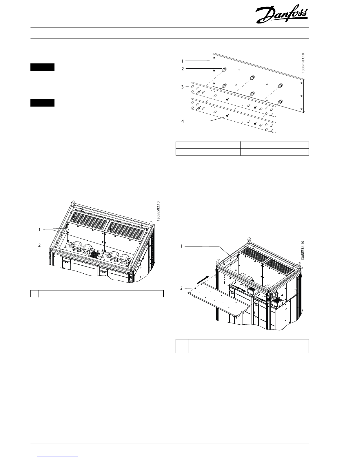
Installing DC-link Bus Bars
1. Install 1 L-bracket inside the top of the enclosure on
each side. Secure each bracket with 3 M5 nuts and
torque to 2.3 Nm (20 in-lb). See Illustration 1.1.
1 L-brackets 2 DC fuse with microswitch
Illustration 1.1 Installation of DC Bus Bar L-brackets above the
DC Fuses
2. Install the 6
stand-os
onto the support plate. Torque
to 2.3 Nm (20 in-lb). Refer to Illustration 1.2.
3. Install the 2 DC-link bus bars onto the support plate
using 3 M5 nuts per bus bar. Torque to 2.3 Nm
(20 in-lb).
1 Support plate 3 DC-link bus bars
2 Stand-os 4 M5 nut
Illustration 1.2 Installing DC-link Bus Bars onto Support Plate
4. With the DC-link bus bars facing downward, slide the
support plate onto the L-brackets. Secure the support
plate with 6 M5 screws and torque to 2.3 Nm (20 inlb). Refer to Illustration 1.3.
5. Install the DC+ and DC- jumper bus bars between
the DC fuses and the DC bus bars. Refer to
Illustration 1.4.
1L-brackets
2 DC-link bus bar assembly (support plate and bus bars)
Illustration 1.3 Installation of DC Bus Bars onto L-brackets
Installation Instructions
Bus Bar Kit for 6-pulse, 2-drive System
VLT® Series FC 102, FC 202, and FC 302
2
Danfoss A/S © 02/2016 All rights reserved. MI92I102
Page 3
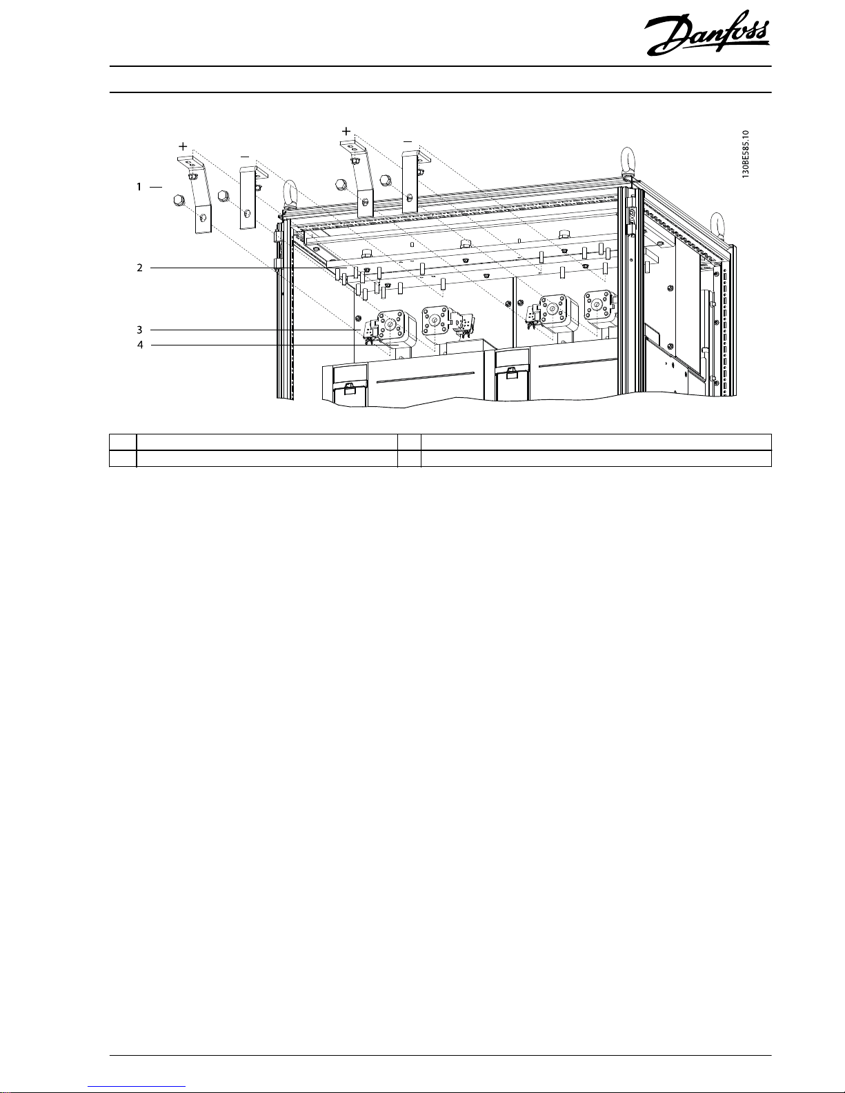
1 DC-link jumper bus bars (+/- indicated in drawing) 3 Microswitch
2 DC-link bus bar 4 DC fuse
Illustration 1.4 Installation of DC Jumper Bus Bars
Installation Instructions
Bus Bar Kit for 6-pulse, 2-drive System
VLT® Series FC 102, FC 202, and FC 302
MI92I102 Danfoss A/S © 02/2016 All rights reserved.
3
Page 4
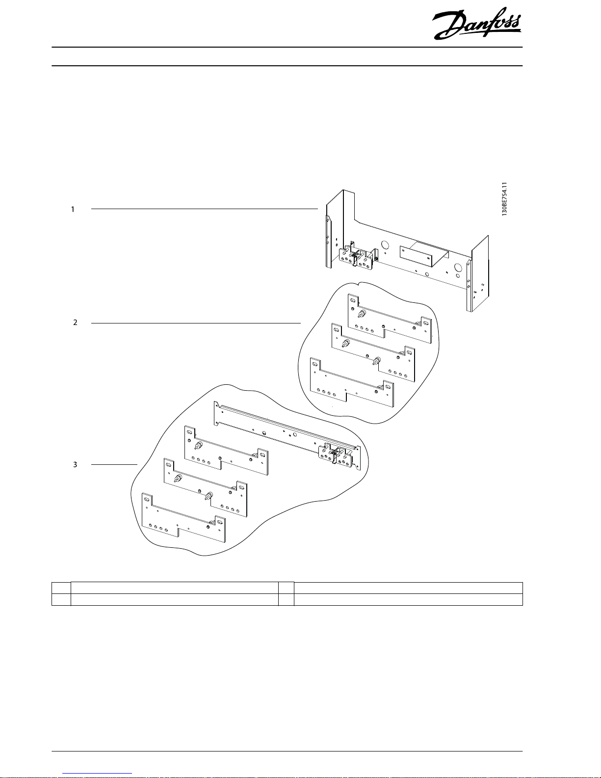
Assembling the AC Bus Bar Subassemblies
The AC bus bar assembly consists of the following 3 subassemblies, as shown in Illustration 1.5:
•
Support subassembly consisting of 3 components
•
Motor bus bar subassembly consisting of 3 components
•
Mains bus bar subassembly consisting of 5 components
1 AC bus bar subassembly bracket 3 Mains bus bar subassembly
2 Motor bus bar subassembly – –
Illustration 1.5 Exploded View of the AC Bus Bar Assembly
Installation Instructions
Bus Bar Kit for 6-pulse, 2-drive System
VLT® Series FC 102, FC 202, and FC 302
4
Danfoss A/S © 02/2016 All rights reserved. MI92I102
Page 5

1. Install the left and right brake terminals onto the brake terminal bracket using 4 M5 nuts. Torque to 2.3 Nm (20 in-lb).
2. Secure the brake terminal assembly to the AC bus bar assembly support with 2 M8 nuts. Torque to 9.6 Nm (85 in-lb). Refer
to Illustration 1.6.
3. Install the mains bus bar S-bracket to the AC bus bar assembly support bracket using 2 M5 nuts. Torque to 2.3 Nm
(20 in-lb).
1 AC bus bar assembly support bracket 4 M5 nut
2 Mounting point for lower EMI/EMC shield 5 Mains bus bar S-bracket
3 Brake terminal assembly (terminals and bracket) 6 Studs that insert into the side support bracket
Illustration 1.6 Assembling the AC Bus Bar Subassembly Bracket
4. Assemble the motor bus bar subassembly using 9 stand-os and 9 M5 nuts. Torque to 2.3 Nm (20 in-lb).
Refer to Illustration 1.7.
1 Slotted opening for M10 screw 3 M5 nut
2 Stand-os (front and back side of bus bar), indicated by an S in
the drawing
4 Solid motor bus bars
Illustration 1.7 Assembling the Motor Bus Bar Subassembly
Installation Instructions
Bus Bar Kit for 6-pulse, 2-drive System
VLT® Series FC 102, FC 202, and FC 302
MI92I102 Danfoss A/S © 02/2016 All rights reserved.
5
Page 6

5. Install the left and right brake terminals onto the brake terminal bracket using 4 M5 nuts. Torque to 2.3 Nm (20 in-lb).
6. Secure the brake terminal assembly to the mains bus bar support with 2 M8 nuts. Torque to 9.6 Nm (85 in-lb). Refer to
Illustration 1.6.
7. Assemble the mains bus bar subassembly using 9
stand-os
and 9 M5 nuts. Torque to 2.3 Nm (20 in-lb).
Refer to Illustration 1.8.
1 Mains bus bar support bracket 4 M5 nut
2 Stand-os (front and back side of bus bar), indicated by an S in
the drawing
5 Brake terminal assembly (terminals and bracket)
3 Slotted opening for M10 screw 6 Solid mains bus bars
Illustration 1.8 Assembling the Mains Bus Bar Subassembly
Installation Instructions
Bus Bar Kit for 6-pulse, 2-drive System
VLT® Series FC 102, FC 202, and FC 302
6
Danfoss A/S © 02/2016 All rights reserved. MI92I102
Page 7

Installing the AC Bus Bar Assembly
1. Install 1 side support bracket inside the enclosure on
each side. Secure each side support bracket with 4
M5 screws and torque to 2.3 Nm (20 in-lb). See
Illustration 1.9.
2. Install ground plate assembly. See Illustration 1.9.
2a Attach the ground support bracket to the
inside of the enclosure. Secure with 4 M5
screws and torque to 2.3 Nm (20 in-lb).
2b Install the ground plate onto the 5 studs on
the ground support bar.
2c Secure the bottom of the ground plate to
the enclosure using 8 M5 screws. Torque to
2.3 Nm (20 in-lb).
2d Install the ground bus bar onto the ground
plate. Secure with 5 M8 nuts and torque to
to 9.6 Nm (85 in-lb).
2e Install the 1 ground jumper plate per drive
module. Secure the bottom of the ground
jumper plate to the top of the ground plate
using 1 M5 nut. Torque to 2.3 Nm (20 in-lb).
2f Secure the top of the ground jumper plate
to the bottom of the drive module reusing
the 2 existing M10 nuts. Torque to 19 Nm
(169 in-lb).
3. Install the ground jumper bus bars. Perform this step
for each drive module.
3a Secure the bottom of the ground jumper
bus bar to the ground bus bar using 1 M5
nut. Torque to 2.3 Nm (20 in-lb). See
Illustration 1.9 for the mounting attachment
points on the ground bus bar.
3b Secure the other end of the ground jumper
bus bar to the drive module ground
terminal using 1 M5 nut. Torque to 2.3 Nm
(20 in-lb).
4. Secure the motor bus bar subassembly (see
Illustration 1.7) to the AC bus bar assembly bracket
(Illustration 1.6) using 3 M5 nuts. Torque to 2.3 Nm
(20 in-lb).
5. Install the AC bus bar bracket/motor bus bar
subassembly to the side support brackets. Secure
each side with 2 M5 nuts and torque to 2.3 Nm
(20 in-lb).
6. Fasten the mains bus bar subassembly (see
Illustration 1.8) to the motor bus bar subassembly
using 4 M5 nuts. Torque to 2.3 Nm (20 in-lb).
7. Shape the
exible
bus bars to
t.
8. Install the motor
exible
bus bars for each drive
module. Refer to Illustration 1.10.
8a Insert 1 M10 screw into each of the slotted
holes in the motor bus bar subassembly,
with the screw shaft facing the front.
8b Install 3
exible
motor bus bars per drive
module, securing 1 end to the screw and
the other end to the drive module terminal.
Secure with 2 M10 nuts per bus bar. Torque
to 19 Nm (169 in-lb).
8c Verify that the proper R, S, T connections
are made. Refer to the Terminal Dimensions
section in the VLT
®
Common AC Drive
Modules Installation Guide.
9. Assemble the front EMI/EMC bracket assembly.
9a Attach the left EMI/EMC bracket to the front
EMI/EMC bracket using 3 M5 screws. Torque
to 2.3 Nm (20 in-lb).
9b Attach the right EMI/EMC bracket to the
front EMI/EMC bracket using 3 M5 screws.
Torque to 2.3 Nm (20 in-lb).
10. Install the front EMI/EMC bracket assembly over each
set of
exible
motor bus bars. Secure with 4 M5 nuts
and torque to 2.3 Nm (20 in-lb). Refer to
Illustration 1.11.
11. Install the exible mains bus bars for each drive
module. Refer to Illustration 1.12.
11a Insert 1 M10 screw into each of the slotted
holes in the mains bus bar subassembly,
with the screw shaft facing the front.
11b Install 3 exible mains bus bars per drive
module, securing 1 end to the screw and
the other end to the drive module mains
terminal. Secure with 2 M10 nuts per bus
bar. Torque to 19 Nm (169 in-lb).
11c Verify the proper U, V, W connections are
made. Refer to the Terminal Dimensions
section in the VLT
®
Common AC Drive
Modules Installation Guide.
12. Install the lower EMI/EMC shield to the AC bus bar
subassembly bracket. Secure with 2 M5 nuts. Torque
to 2.3 Nm (20 in-lb). See Illustration 1.13.
Installation Instructions
Bus Bar Kit for 6-pulse, 2-drive System
VLT® Series FC 102, FC 202, and FC 302
MI92I102 Danfoss A/S © 02/2016 All rights reserved.
7
Page 8

1 Screw at the bottom of the drive module that connects
to the top of the ground jumper plate
6 Ground bus bar
2 M10 nut 7 Ground jumper bus bar
3 Ground jumper plate 8 Side support bracket
4 M5 nut 9 Ground support bracket
5Ground plate ––
Illustration 1.9 Installation of Side Support Brackets and Ground Bus Bar Assembly
Installation Instructions
Bus Bar Kit for 6-pulse, 2-drive System
VLT® Series FC 102, FC 202, and FC 302
8
Danfoss A/S © 02/2016 All rights reserved. MI92I102
Page 9

1 Motor bus bar screws for drive module 1 4 M10 nuts
2 Motor bus bar subassembly 5 Flexible motor bus bars
3 Motor bus bar screws for drive module 2 – –
Illustration 1.10 Installation of Flexible Motor Bus Bars
Installation Instructions
Bus Bar Kit for 6-pulse, 2-drive System
VLT® Series FC 102, FC 202, and FC 302
MI92I102 Danfoss A/S © 02/2016 All rights reserved.
9
Page 10

1 Left EMI/EMC bracket (shown on drive module 1) 4 Ground plate
2 Front EMI/EMC bracket (shown on drive module 1) 5 Right EMI/EMC bracket (shown on drive module 1)
3 Flexible motor bus bars – –
Illustration 1.11 Installation of Front EMI/EMC Bracket Assembly
Installation Instructions
Bus Bar Kit for 6-pulse, 2-drive System
VLT® Series FC 102, FC 202, and FC 302
10
Danfoss A/S © 02/2016 All rights reserved. MI92I102
Page 11

1 Mains bus bar screws for drive module 1 4 Front EMI/EMC bracket assembly
2 Flexible mains bus bars 5 Mains bus bar screws for drive module 2
3 M10 Nuts 6 Mains bus bar subassembly
Illustration 1.12 Installation of Flexible Mains Bus Bars and Lower EMI/EMC Shield
Installation Instructions
Bus Bar Kit for 6-pulse, 2-drive System
VLT® Series FC 102, FC 202, and FC 302
MI92I102 Danfoss A/S © 02/2016 All rights reserved.
11
Page 12

1 DC-link bus bars (under mesh screen) 7 Flexible motor bus bars for drive module 2
2 Solid mains bus bars 8 Front EMI/EMC bracket assembly for drive module 2
3 Ground bar support bracket 9 Flexible mains bus bars for drive module 2
4 Ground bus bar 10 Solid motor bus bars for drive module 2
5 Ground plate 11 Lower EMI/EMC shield
6 Drive module 2 – –
Illustration 1.13 Installing Lower EMI/EMC Shield on an Assembled 2-Drive System canceled
Danfoss can accept no responsibility for possible errors in catalogues, brochures and other printed material. Danfoss reserves the right to alter its products without notice. This also applies to products already on
order provided that such alterations can be made without subsequential changes being necessary in specifications already agreed. All trademarks in this material are property of the respective companies. Danfoss
and the Danfoss logotype are trademarks of Danfoss A/S. All rights reserved.
Danfoss A/S
Ulsnaes 1
DK-6300 Graasten
vlt-drives.danfoss.com
*MI92I102*
MI92I102130R0689 02/2016
 Loading...