

Page 1
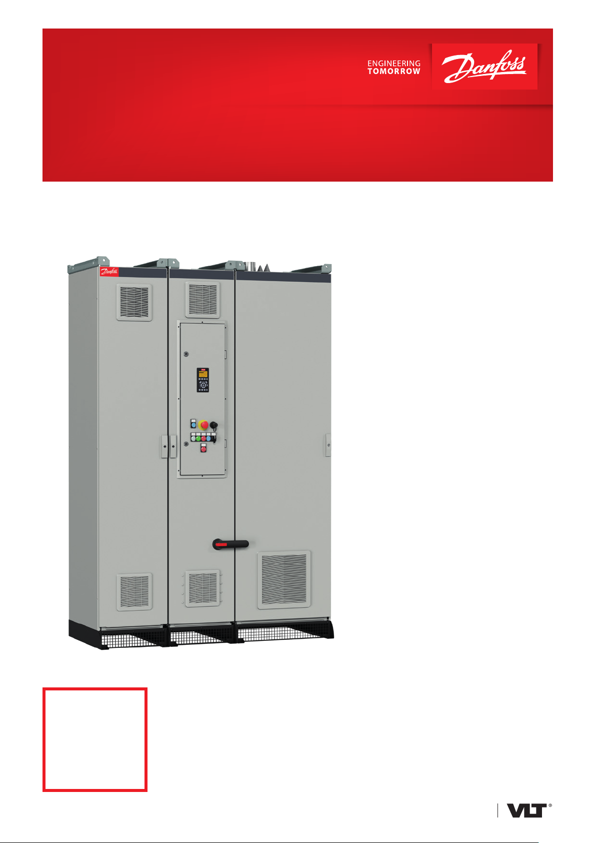
Fact Sheet: VLT® Enclosed Drives
Extended functionality and real LHD for
high-performance operation
VLT® Enclosed Drives have been designed to meet the most demanding requirements for flexibility, robustness,
compactness and service-friendliness, making them a smart choice for diverse applications. They are ideal for low
harmonic drive (LHD) usage, with outstanding harmonic mitigation performance.
VLT® Enclosed Drives are
configurable with input/output filters,
control and enclosure options to meet
practically all requirements of the
application, eliminating the need for an
extra enclosure.
Selectable input/output filters ensure
highest quality of the voltage on
motor terminals, as well as the lowest
harmonics content of mains currents –
TDD <3% and it is a best choice, when
harmonics frequencies above 2 kHz in
the power supply network is a concern
to fulfil the IEC 61000-2-4 requirements
for harmonics up to 9 kHz.
<3%
Total harmonic
distortion, even
up to 9 kHz
Real LHD
Available for enclosure sizes
D and E
n VLT® AutomationDrive FC 302
n VLT® AQUA Drive FC 202
n VLT® HVAC Drive FC 102
n VLT® Refrigeration Drive FC 103
Protection ratings
n IP21 (Type 1)
n IP54 (Type 12)
Back-channel cooling
A unique ducted back-channel passes
cooling air over heat sinks with minimal
air passing through the electronics area.
There is an IP54/Type 12 seal between
the back-channel cooling duct and
the electronics area of the VLT® drive.
This allows 90% of the heat losses to
be exhausted directly outside of the
enclosure, improving reliability and
prolonging life by dramatically reducing
temperature rise and contamination
of the electronic components. Input/
output filters also use the IP54/ Type 12
-rated back-channel for cooling.
Supply voltage
and power ranges
n 380-480/500 V……90 kW-500 kW
n 525-690 V…….90 kW-710 kW
with 150% overload
drives.danfoss.com
Page 2
Feature Benefit
Built-in options
Back-channel cooling
Variable speed cooling fans Improve efficiency of the drive and reduce audible noise.
VLT® drives family with
common graphical LCP
Integrated selectable input/output filters
Door-mounted control compartment Safe accessibility to control terminals, also during operation of the drive.
10
9
8
3
4
7
5
6
Eliminate the need for an extra cabinet when options are required. Save cost on equipment and
reduce space requirements.
Reduce the scale of air conditioning required for the room, and even reduce the room size, for savings
in up-front cost and operating expenses.
Know one drive, know them all. Save time and cost for training, service, ordering and spare parts
logistics.
Ensure highest quality of the voltage on motor terminals, as well as the lowest harmonics content of
the mains currents.
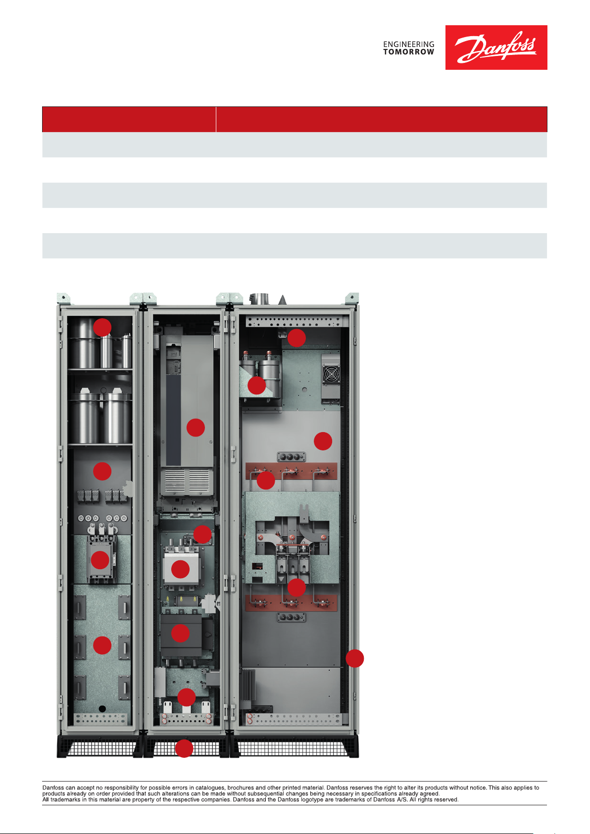
1 VLT® drive: Drives with enclosure size
D and E with selectable control options
cards.
11
12
1
13
14
2
15
16
2 Back-channel cooling assembly
ensures utilization of the drive’s backchannel cooling concept in the cabinet.
3 Mains contactor is a selectable mains
power option.
4 Mains switch disconnect is a
selectable mains power option
5 Bottom entry establishment ensures
IP54/NEMA12 connections to the power
supply.
6 Plinth is available as an option in
100 mm, 200 mm, and 400 mm sizes.
7 Magnetics of the input filter
assembly
ensures the low harmonics content of
mains currents - TDD<3%.
8 Contactor to control the harmonics
filter of the drive.
9 Back-channel cooling assembly for
input harmonic filter ensures efficient
cooling of magnetics.
10 Capacitors assembly of the input
harmonics filter.
11 Top-exit establishment ensures
IP54/NEMA12 connections of motor cables
from the top.
12 Capacitors assembly of the output
sine-wave filter.
13 Back-channel cooling assembly for
magnetics of the output sine-wave filter.
14 Sine-wave filter magnetics of the
output filter, as a selectable power option.
15 Motor connection terminals are
placed in the sine-wave filter cabinet of the
enclosed drive.
16 Enclosed drive cabinet utilizes Rittal
TS8 baying system.
DKDD.PFP.416.A1.02 © Copyright Danfoss Drives | 2019.09
 Loading...