

Page 1

INSTRUCTIONS 177R0076
INSTALLATION OF TOP AND BOTTOM COVERS FOR IP00 FRAMES D3, D4 & E2
INTO RITTAL ENCLOSURES
This instruction sheet is for the installation of the top and bottom covers onto IP00 VLTs® to direct the
heat sink cooling air in and out the back of the frequency converter. The kits are applicable to IP00 drive
frames D3, D4 and E2. These kits are designed and tested to be used with IP00/Chassis drives in Rittal TS8 enclosures.
Notes:
1. If external duct work is added to the exhaust path of the drive, additional back pressure will be created that will reduce the cooling of the drive. The drive must be derated to accommodate the reduced cooling. First, the pressure drop must be calculated, then refer to the derating tables located
in the VLT High Power Operating Instructions.
2. A doorfan(s) is required on the enclosure to remove the heat losses not contained in the backchannel of the drive and any additional losses generated from other components installed inside the enclosure. The total required air flow must be calculated so that the appropriate fans can be selected.
Some enclosure manufacturers offer software for performing the calculations (i.e. Rittal Therm software).
If the VLT is the only heat generating component in the enclosure, the minimum airflow required at
3
an ambient temperature of 45°C for the D3 and D4 frame drives is 391 m
mum airflow required at an ambient temperature of 45°C for the E2 frame drive is 782 m
/h (230 cfm). The mini-
3
/h (460
cfm).
Used with:
VLT4000, VLT5000, VLT6000, VLT8000,
VLT-HVAC, VLT-AQUA, VLT-Automation
Frame D3 Kit Part No. 176F1781
Required Tools
• Metric Socket Set, 7-19mm
• Socket Extensions
• Torx Driver Set T10-T40
• Torque Wrench 6-50 in-lbs (.7-6 N-M)
Frame D4 Kit Part No. 176F1782
Frame E2 Kit Part No. 176F1783
Torque Requirements
1. M5 screws/nuts torque to 20 in-lbs (2.3 N-M)
The kit consist of the following parts:
• Drive mounting plate
• Top vent cover
2. M6 screws/nuts torque to 35 in-lbs ( 3.9 N-M)
3. M10 nuts torque to 170 in-lbs (20 N-M)
4. T25 Torx screws torque to 20 in-lbs (2.3 N-M)
• Bottom air inlet cover
• Gasket materi a l
MI.38.J1.02 - VLT® is a Danfoss Registered Trademark 1
Page 2
Note: The photos in this Instruction Sheet represent a D-Frame drive. E-Frame drives use parts similar
to those in the photos however they are sized appropriately for the E-Frame drives.
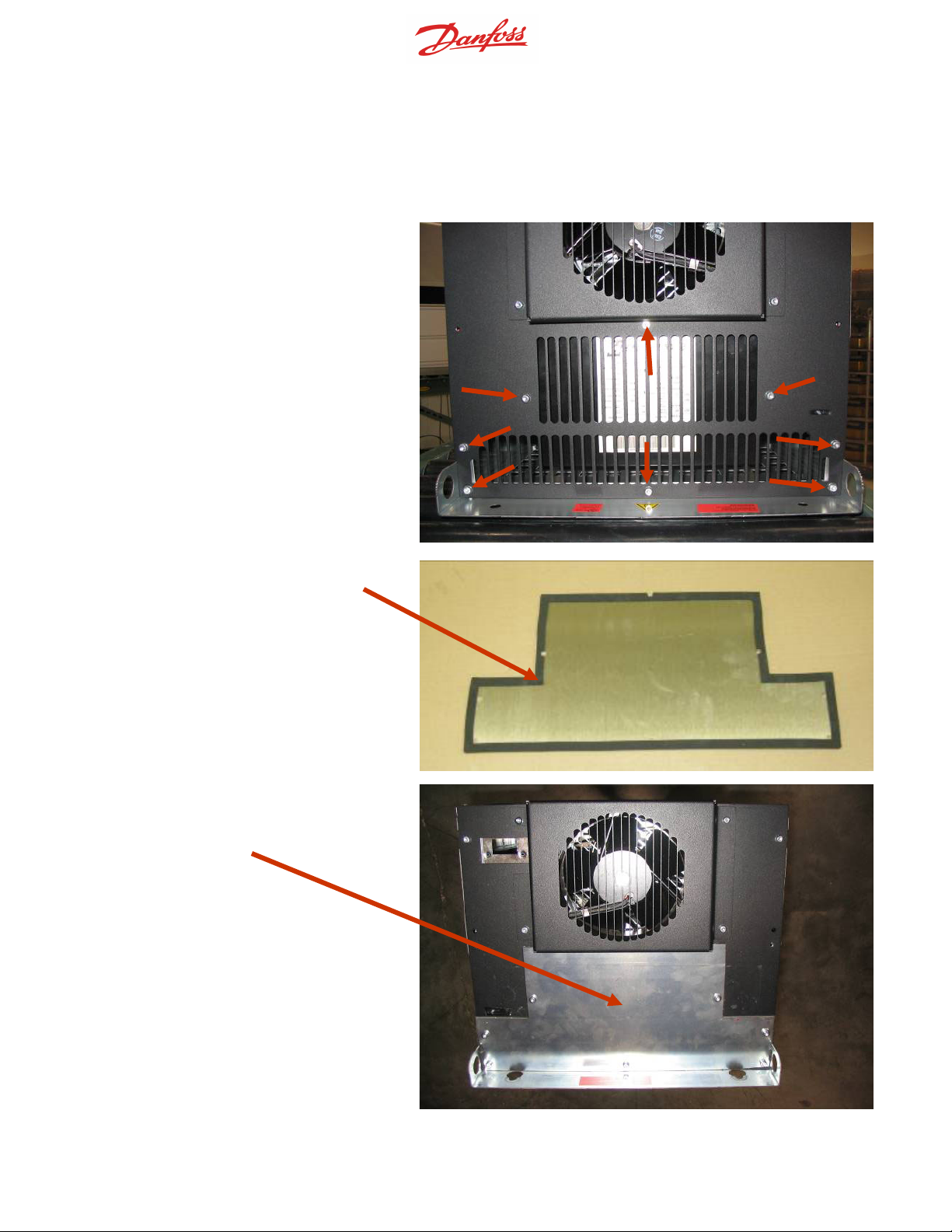
Remove the screws from the top of drive.
Note: remove only the screws locate toward the back half of the drive. Do not
remove the screws that are securing the
fan in place.
Install the gasket on the top cover plate.
Install the top duct cover plate as shown
using the new 16mm, M5 screws provided with the kit
Instruction No: 177R0076 V0 Aug 13, 2008 Page 2
MI.38.J1.02 - VLT® is a Danfoss Registered Trademark 2
Page 3

Install the two mounting clips on the bottom of the frame as shown. Note that the
E2 frame VLT utilizes six mounting clips
for the bottom cover plate.
Install the gasket on the bottom cover
plate.
Instruction No: 177R0076 V0 Aug 13, 2008 Page 3
MI.38.J1.02 - VLT® is a Danfoss Registered Trademark 3
Page 4

Install the bottom cover plate as shown.
Note: if the VLT is being installed inside a
panel, install the bottom cover plate after
the VLT has been installed in the panel to
allow access to the drive mounting holes
located on the bottom of the drive.
Mount the drive mounting plate in the enclosure using the “in frame” mounting position.
Instruction No: 177R0076 V0 Aug 13, 2008 Page 4
MI.38.J1.02 - VLT® is a Danfoss Registered Trademark 4
Page 5

Use the drive mounting plate as a template to mark the
openings for the air intake and exhaust along with
mounting screw holes on the rear panel of the enclosure.
Remove the rear panel of the enclosure and cut openings and drill mounting holes.
Install gasket material on both sides of the drive
mounting plate.
Install gasket material on both sides of the drive
mounting plate.
Instruction No: 177R0076 V0 Aug 13, 2008 Page 5
MI.38.J1.02 - VLT® is a Danfoss Registered Trademark 5
Page 6

Install the drive on the drive mounting plate using the
four studs on the top and bottom of the mounting
plate. M10 nuts are provided for drive mounting.
Install the bottom air inlet cover on the drive.
Re-install the rear panel of the enclosure.
Instruction No: 177R0076 V0 Aug 13, 2008 Page 6
MI.38.J1.02 - VLT® is a Danfoss Registered Trademark 6
 Loading...