

Page 1
MAKING MODERN LIVING POSSIBLE
Operating Instructions
VLT® DriveMotor FCP 106/FCM 106
vlt-drives.danfoss.com
Page 2

Page 3

Contents Operating Instructions
Contents
1 Introduction
1.1 Purpose of the Manual
1.2 Additional Resources
1.3 Product Overview
1.3.1 Intended Use 5
1.3.2 Electrical Overview 6
1.4 Approvals
1.5 Disposal Instruction
2 Safety
2.1 Qualied Personnel
2.2 Safety Precautions
3 Mechanical Installation
3.1 Unpacking
3.1.1 Items Supplied, FCP 106 11
3.1.2 Further Items Required, FCP 106 11
3.1.3 Items Supplied, FCM 106 11
4
4
5
5
7
7
8
8
8
11
11
3.1.4 Identication of Unit 11
3.1.5 Nameplates 11
3.1.6 Lifting 12
3.2 Installation Environment
3.3 Mounting
3.3.1 Introduction 13
3.3.2 Prepare Gasket 13
3.3.3 Prepare Adapter Plate 14
3.3.4 Mount the DriveMotor 15
3.3.5 Shaft Alignment 15
3.3.6 Bearing Life and Lubrication 16
4 Electrical Installation
4.1 Safety Instructions
4.2 IT Mains
4.3 EMC-compliant Installation
4.4 Cable Requirements
4.5 Grounding
12
13
18
18
19
20
22
22
4.6 Motor Connection
4.6.1 Connect FCP 106 to Motor 22
4.6.2 Thermistor Input from Motor 24
4.7 AC Mains Connection
MG03L302 Danfoss A/S © 11/2015 All rights reserved. 1
22
24
Page 4

Contents VLT® DriveMotor FCP 106/FCM 106
4.8 Control Wiring
4.8.1 Control Terminals and Relays 2 25
4.8.2 Control Terminals and Relays 3 25
4.8.3 Load Sharing 26
4.8.4 Brake 26
4.9 Installation Checklist
4.9.1 Recommendations for UL-listed PRGY Systems 28
5 Commissioning
5.1 Applying Power
5.2 Local Control Panel Operation
5.3 Memory Module MCM 101
5.3.1 Conguring with the VLT® Memory Module MCM 101 31
5.4 Basic Programming
5.4.1 Conguration for Open-loop Applications 32
5.4.2 Set-up Wizard for Closed-loop Applications 34
5.4.3 Quick Menu Motor Set-up 35
5.4.4 Changing Parameter Settings 36
25
27
29
29
29
31
31
5.4.5 Thermistor Set-up 36
6 Maintenance, Diagnostics and Troubleshooting
6.1 Maintenance
6.2 List of Warnings and Alarms
7 Specications
7.1 Clearances, Dimensions and Weights
7.1.1 Clearances 40
7.1.2 FCP 106 Dimensions 41
7.1.3 FCM 106 Dimensions 42
7.1.4 Weight 45
7.2 Electrical Data
7.2.1 Mains Supply 3x380–480 V AC Normal and High Overload 46
7.3 Mains Supply
7.4 Protection and Features
7.5 Ambient Conditions
7.6 Cable Specications
37
37
37
40
40
46
48
48
48
49
7.7 Control Input/Output and Control Data
7.8 Connection Tightening Torques
7.9 FCM 106 Motor Specications
7.10 Fuse and Circuit Breaker Specications
8 Appendix
2 Danfoss A/S © 11/2015 All rights reserved. MG03L302
49
51
51
52
54
Page 5

Contents Operating Instructions
8.1 Abbreviations and Conventions
8.2 Parameter Menu Structure
Index
54
54
57
MG03L302 Danfoss A/S © 11/2015 All rights reserved. 3
Page 6
195NA447.10
195NA419.10
Introduction VLT® DriveMotor FCP 106/FCM 106
11
1 Introduction
1.1 Purpose of the Manual
This manual provides information required to install and
commission the frequency converter.
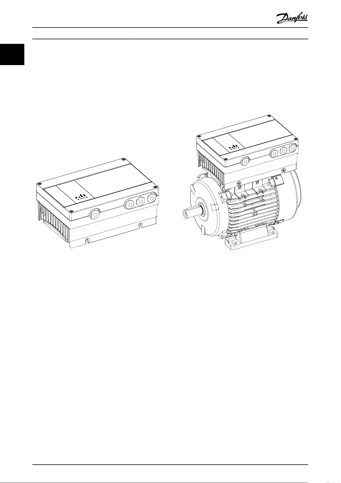
VLT® DriveMotor FCP 106
The delivery comprises the frequency converter only. A
wall mount adapter plate, or motor adapter plate and
power crimp terminals are also required for installation.
Order the wall mount kit or adapter plate and power crimp
terminals separately.
VLT® DriveMotor FCM 106
The frequency converter is mounted onto the motor at
delivery. The combined FCP 106 and motor is known as
the VLT® DriveMotor FCM 106.
Illustration 1.1 FCP 106
Illustration 1.2 FCM 106
4 Danfoss A/S © 11/2015 All rights reserved. MG03L302
Page 7

Introduction Operating Instructions
1.2 Additional Resources
Available literature:
VLT® DriveMotor FCP 106/FCM 106 Operating
•
Instructions, for information required to install and
commission the frequency converter.
®
DriveMotor FCP 106/FCM 106 Design Guide
VLT
•
provides information required for integration of
the frequency converter into a diversity of
applications.
VLT® DriveMotor FCP 106/FCM 106 Programming
•
Guide, for how to program the unit, including
complete parameter descriptions.
®
LCP Instruction, for operation of the local
VLT
•
control panel (LCP).
VLT® LOP Instruction, for operation of the local
•
operation pad (LOP).
Modbus RTU Operating Instructions and VLT
•
DriveMotor FCP 106/FCM 106 BACnet Operating
Instructions for information required for
controlling, monitoring, and programming of the
frequency converter.
The VLT® PROFIBUS DP MCA 101 Installation Guide
•
provides information about installing the
PROFIBUS and troubleshooting.
The VLT® PROFIBUS DP MCA 101 Programming
•
Guide provides information about conguring the
system, controlling the frequency converter,
accessing the frequency converter, programming,
and troubleshooting. It also contains some typical
application examples.
Technical literature and approvals are available online at
vlt-drives.danfoss.com/Support/Service/.
Danfoss VLT® Energy Box software is available at
www.danfoss.com/BusinessAreas/DrivesSolutions, PC software
download area.
1 1
1.3 Product Overview
1.3.1 Intended Use
The frequency converter is an electronic motor controller
intended for:
Regulation of motor speed in response to system
•
feedback or to remote commands from external
controllers. A power drive system consists of:
- The frequency converter.
- The motor.
- Equipment driven by the motor.
®
The frequency converter can also be used for motor
overload protection. The frequency converter is allowed for
use in residential, industrial, and commercial environments
in accordance with local laws and standards.
Depending on conguration, the frequency converter can
be used in standalone applications or form part of a larger
application or installation.
When using a motor with thermal protection, the
frequency converter is allowed for use in residential,
industrial, and commercial environments in accordance
with local laws and standards.
System and motor status surveillance.
•
VLT® Motion Control Tool MCT 10 enables congu-
•
ration of the frequency converter from a
Windows™-based PC environment.
Danfoss VLT® Energy Box software, for energy
•
calculation in HVAC applications.
MG03L302 Danfoss A/S © 11/2015 All rights reserved. 5
Foreseeable misuse
Do not use the frequency converter in applications which
are non-compliant with
environments. Ensure compliance with the conditions
specied in chapter 7 Specications.
specied operating conditions and
Page 8
195NA507.11
L1
L2
L3
PE
3-phase
power
input
+10 V DC
0–10 V DC 0/4–20 mA
0/4–20 mA
0–10 V DC -
50 (+10 V OUT)
53 (A IN)
54 (A IN)
55 (COM A IN/OUT)
42 0/4–20 mA A OUT/DIG OUT
45 0/4–20 mA A OUT/DIG OUT
12 (+24 V OUT)
18 (DIGI IN)
19 (DIGI IN)
20 (COM D IN)
27 (DIGI IN)
29 (DIGI IN)
PROFIBUS
MCM
24 V (NPN)
0 V (PNP)
24 V (NPN)
0 V (PNP)
24 V (NPN)
0 V (PNP)
24 V (NPN)
0 V (PNP)
Bus ter.
RS485
Interface
(N RS485) 69
(P RS485) 68
(Com RS485) 61
RS485
(PNP)-Source
(NPN)-Sink
Bus ter.
1 2
ON
ON=Terminated
OFF=Unterminated
03
02
01
relay 1
240 V AC 3A
06
05
04
relay 2
240 V AC 3A
UDC+
UDC-
PE
Motor
U
V
W
T1
T2
Thermistor
located in
motor
Group 5-*
Located in
motor block
Introduction VLT® DriveMotor FCP 106/FCM 106
11
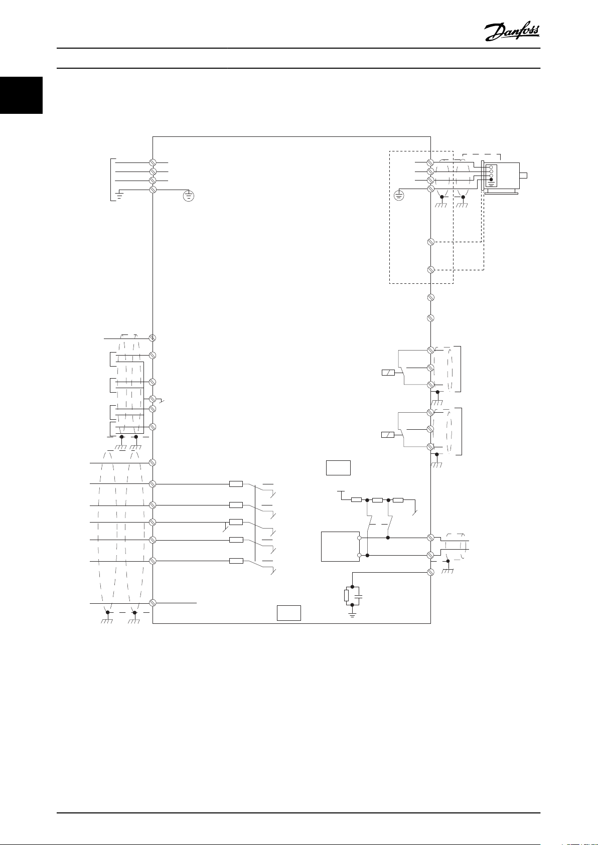
1.3.2 Electrical Overview
Illustration 1.3 Electrical Overview
6 Danfoss A/S © 11/2015 All rights reserved. MG03L302
Page 9
Introduction Operating Instructions
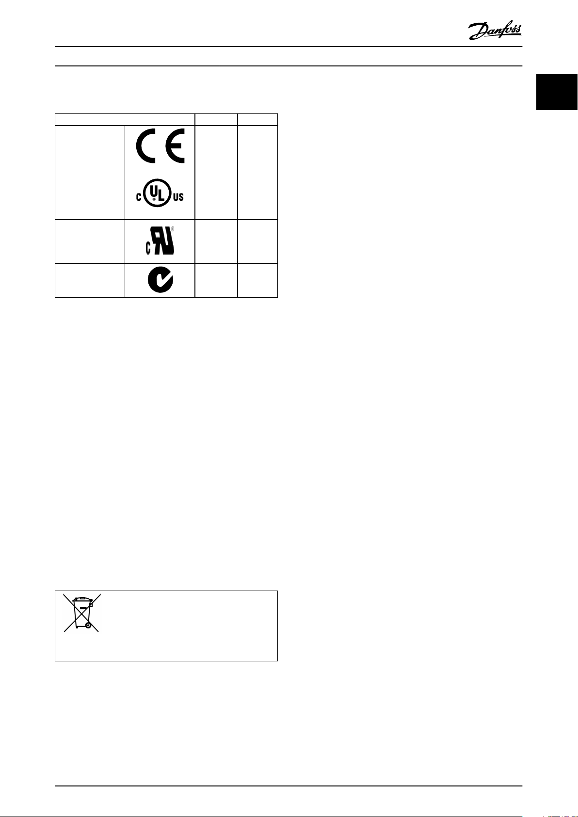
1.4 Approvals
Certication FCP 106 FCM 106
EC Declaration of
Conformity
UL listed –
UL recognized
C-tick
The EC declaration of conformity is based on the following
directives:
Low Voltage Directive 2006/95/EC, based on EN
•
61800-5-1 (2007).
EMC Directive 2004/108/EC, based on EN 61800-3
•
(2004).
UL listed
Product evaluation is complete and the product can be
installed in a system. The system must also be UL listed by
the appropriate party.
UL recognized
More evaluation is required before the combined
frequency converter and motor can be operated. The
system in which the product is installed must also be UL
listed by the appropriate party.
The frequency converter complies with UL 508C thermal
memory retention requirements. For more information,
refer to the section Motor Thermal Protection in the
product-specic design guide.
✓ ✓
✓
✓ ✓
✓
–
1 1
Disposal Instruction
1.5
Equipment containing electrical components
must not be disposed of together with domestic
waste.
It must be separately collected with electrical
and electronic waste according to local and
currently valid legislation.
MG03L302 Danfoss A/S © 11/2015 All rights reserved. 7
Page 10
Safety VLT® DriveMotor FCP 106/FCM 106
2 Safety
22
The following symbols are used in this manual:
WARNING
Indicates a potentially hazardous situation that could
result in death or serious injury.
CAUTION
Indicates a potentially hazardous situation that could
result in minor or moderate injury. It can also be used to
alert against unsafe practices.
NOTICE
Indicates important information, including situations that
can result in damage to equipment or property.
2.1 Qualied Personnel
Correct and reliable transport, storage, installation,
operation, and maintenance are required for the troublefree and safe operation of the frequency converter. Only
qualied personnel are allowed to install and operate this
equipment.
Qualied personnel are dened as trained sta, who are
authorized to install, commission, and maintain equipment,
systems, and circuits in accordance with pertinent laws and
regulations. Additionally, the qualied personnel must be
familiar with the instructions and safety measures
described in these operating instructions.
Safety Precautions
2.2
WARNING
HIGH VOLTAGE
Frequency converters contain high voltage when
connected to AC mains input power. Failure to perform
installation, start-up, and maintenance by qualied
personnel could result in death or serious injury.
Only qualied personnel are permitted to
•
perform installation, start-up, and maintenance.
WARNING
UNINTENDED START
When the frequency converter is connected to AC mains,
DC supply, or load sharing, the motor can start at any
time. Unintended start during programming, service, or
repair work can result in death, serious injury, or
property damage. The motor can start with an external
switch, a eldbus command, an input reference signal
from the LCP or LOP, via remote operation using a
software tool, or after a cleared fault condition.
To prevent unintended motor start:
Disconnect the frequency converter from mains.
•
Press [O/Reset] on the LCP before
•
programming parameters.
Ensure that the frequency converter, motor, and
•
any driven equipment are fully wired and
assembled when the frequency converter is
connected to AC mains, DC supply, or load
sharing.
WARNING
DISCHARGE TIME
The frequency converter contains DC-link capacitors,
which can remain charged even when the frequency
converter is not powered. High voltage can be present
even when the warning LED indicator lights are o.
Failure to wait the specied time after power has been
removed before performing service or repair work can
result in death or serious injury.
Stop the motor.
•
Disconnect AC mains and remote DC-link power
•
supplies, including battery back-ups, UPS, and
DC-link connections to other frequency
converters.
Disconnect or lock PM motor.
•
Wait for the capacitors to discharge fully. The
•
minimum duration of waiting time is specied
in Table 2.1.
Before performing any service or repair work,
•
use an appropriate voltage measuring device to
make sure that the capacitors are fully
discharged.
8 Danfoss A/S © 11/2015 All rights reserved. MG03L302
Page 11
Safety Operating Instructions
Voltage
[V]
3x400 0.55–7.5 (0.75–10) 4
Table 2.1 Discharge Time
1) Power ratings relate to normal overload (NO).
Power range
[kW (hp)]
1)
Minimum waiting
time
(minutes)
WARNING
RISK OF DEATH OR SERIOUS INJURY
According to UL 508C, the VLT® DriveMotor FCP 106 and
VLT® DriveMotor FCM 106 do not support the use of
delta grounded grid.
Using the VLT® DriveMotor FCP 106 or VLT® DriveMotor
FCM 106 on a delta grounded grid may cause death or
serious injury.
To avoid the risk:
Do not install VLT® DriveMotor FCP 106 and
•
VLT® DriveMotor FCM 106 on a delta grounded
grid.
WARNING
EQUIPMENT HAZARD
Contact with rotating shafts and electrical equipment
can result in death or serious injury.
Ensure that only trained and qualied personnel
•
perform installation, start-up, and maintenance.
Ensure that electrical work conforms to national
•
and local electrical codes.
Follow the procedures in this guide.
•
WARNING
LEAKAGE CURRENT HAZARD
Follow national and local codes regarding protective
earthing (PE) of equipment with a leakage current
exceeding 3.5 mA. Frequency converter technology
implies high frequency switching at high power. This
switching generates a leakage current in the ground
connection. A fault current in the frequency converter at
the output power terminals can contain a DC
component. The DC component can charge the lter
capacitors and cause a transient ground current. The
ground leakage current depends on various system
congurations including RFI ltering, screened motor
cables, and frequency converter power. EN/IEC 61800-5-1
(Power Drive System Product Standard) requires special
care because the leakage current exceeds 3.5 mA. See EN
60364-5-54 section 543.7 for further information.
Ensure correct grounding of the equipment by a
•
certied electrical installer.
Grounding must be reinforced in one of the
•
following ways:
- Ensure that the ground wire has a
cross-section of at least 10 mm2 (7
AWG).
- Ensure that 2 separate ground wires
are used, both complying with the
dimensioning rules.
NOTICE
HIGH ALTITUDES
For installation at altitudes above 2000 m (6562 ft),
contact Danfoss regarding PELV.
2 2
WARNING
UNINTENDED MOTOR ROTATION
WINDMILLING
Unintended rotation of permanent magnet motors
creates voltage and can charge the unit, resulting in
death, serious injury, or equipment damage.
Ensure that permanent magnet motors are
•
blocked to prevent unintended rotation.
MG03L302 Danfoss A/S © 11/2015 All rights reserved. 9
WARNING
DC CURRENT RISK
This product can cause a DC current in the protective
conductor. Failure to follow the precautions can lead to
personal injury or property damage.
Take the following precautions:
When using a residual current device (RCD) for
•
extra protection, use only an RCD of Type B
(time delayed) on the supply side of this
product.
Protective earthing (PE) of the frequency
•
converter and the use of RCDs must always
follow national and local regulations.
Page 12

Safety VLT® DriveMotor FCP 106/FCM 106
WARNING
GROUNDING HAZARD
22
For operator safety, it is important to ground the
frequency converter properly in accordance with national
and local electrical codes, as well as the instructions in
this manual. Ground currents are higher than 3.5 mA.
Failure to ground the frequency converter properly could
result in death or serious injury.
It is the responsibility of the user, or certied electrical
installer, to ensure correct grounding of the equipment
according to national, and local electrical codes and
standards.
Follow all local and national electrical codes to
•
ground electrical equipment properly.
Establish proper protective grounding for
•
equipment with current higher than 3.5 mA.
A dedicated ground wire is required for input
•
power, motor power, and control wiring.
Use the clamps provided on the equipment for
•
proper ground connections.
Do not ground one frequency converter to
•
another in a daisy chain fashion.
Keep the ground wire connections as short as
•
possible.
Use high-strand wire to reduce electrical noise.
•
Follow the motor manufacturer’s wiring
•
requirements.
10 Danfoss A/S © 11/2015 All rights reserved. MG03L302
Page 13
1
2 3
456
Enclosure: IP66 , Tamb. 40
C / 104 F
V LT
MADE IN
DENMARK
R
P/N: 134G2844 S/N: 010400G253
4.0kW(400V) / 5.0HP(460V)
IN: 3x380-480V 50/60Hz , 8.3/6.8A
OUT: 3x0-Vin 0-400Hz , 9.0/8.2A
o
*1 3 1U3 9 3 0 0 1 0 1 0 2 G 2 9 0 *
Drive Motor
www.danfoss.com
T/C: FCP106P4K0T4C66H1FSXXAXX
Enclosure rating: See manual
E134261 Ind. Contr. Eq.
o
7
8
9
10
11
195NA484.11
Mechanical Installation Operating Instructions
3 Mechanical Installation
3.1 Unpacking
NOTICE
INSTALLATION - EQUIPMENT DAMAGE RISK
Incorrect installation can result in equipment damage.
Before installation, check for fan cover damage,
•
shaft damage, foot or mounting damage, and
loose fasteners.
Check nameplate details.
•
Ensure level mounting surface, balanced
•
mounting. Avoid misalignment.
Ensure that gaskets, sealants, and guards are
•
correctly tted.
Ensure correct belt tension.
•
3.1.1 Items Supplied, FCP 106
Check that all items are included:
1 FCP 106 frequency converter.
•
1 accessory bag.
•
1 VLT® Memory Module MCM 101.
•
Operating instructions.
•
3.1.3 Items Supplied, FCM 106
Check that all items are included:
1 FCM 106 frequency converter with motor.
•
1 accessory bag.
•
Operating Instructions.
•
3.1.4 Identication of Unit
Items supplied may vary according to product congu-
ration.
Make sure the items supplied and the information
•
on the nameplate correspond to the order conrmation.
Check the packaging and the frequency converter
•
visually for damage caused by inappropriate
handling during shipment. File any claim for
damage with the carrier. Retain damaged parts
for clarication.
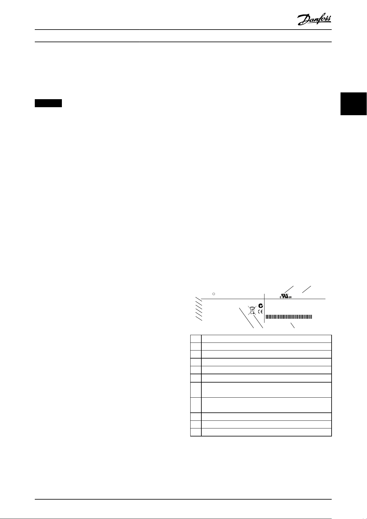
3.1.5 Nameplates
3 3
3.1.2 Further Items Required, FCP 106
1 adapter plate (wall mount adapter plate or
•
motor adapter plate).
1 gasket, used between motor adapter plate and
•
frequency converter.
1 motor connector.
•
4 screws for fastening frequency converter to
•
adapter plate.
4 screws for fastening motor adapter plate to
•
motor.
Crimp terminals:
•
- AMP standard power timer contacts
female, see chapter 4.6.1 Connect FCP
106 to Motor for ordering numbers.
- 3 pieces for motor terminals, U, V, and
W.
- 2 pieces for thermistor (optional).
- 1 piece for grounding terminal.
2 guiding pins (optional).
•
MG03L302 Danfoss A/S © 11/2015 All rights reserved. 11
1 Type code
2 Certications
3 Enclosure rating
4 Bar code for manufacturer use
5 Certications
6
Serial number
Enclosure type and IP rating, maximum ambient
7
temperature without derating
Output voltage, frequency, and current (at low/high
8
voltages)
9 Input voltage, frequency, and current (at low/high voltages)
10 Power rating
11 Ordering number
Illustration 3.1 FCP 106 Nameplate (Example)
1) Example of format: Serial number ‘xxxxx253’ indicates
manufacture in week 25, year 2013.
1)
Page 14
195NA483.10
V LT
MOTOR REF: HPS112 1500 159
Drive Motor
www.danfoss.com
T/C: FCM106P7K5T4C55H1FSXXAXXE4N7K5150B03000
Listed E347257
EP Motors for Ind. Use
Enclosure rating Type 12
Tamb. 40
C/104 F
o
o
1
MADE IN DENMARK
P/N: 134L4306 S/N: 000000G000
IN: 3X380-480V, 50-60Hz, 15/13A
Out: 7.5kW(400V) / 10HP(460V)
Cos /PF: 0.98 / 0.96
ϕ
MSV: &OEM4&
DUTY Class S1IP55
0-1500 min /50Hz
-1
Wt 14.5 kg
5
2
3
4
6
789
10
11
12
13
14
15
DBV: &OEM3&
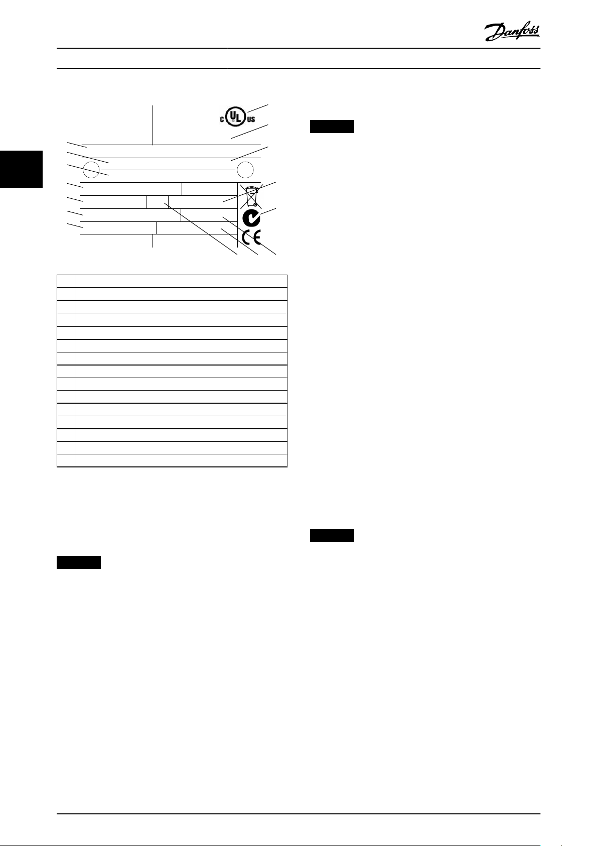
Mechanical Installation VLT® DriveMotor FCP 106/FCM 106
3.1.6 Lifting
NOTICE
LIFTING - EQUIPMENT DAMAGE RISK
Incorrect lifting can result in equipment damage.
Use both lifting lugs when provided.
33
1 Type code
2 Certications
3 Enclosure rating
4
Serial number
5 Motor duty class
6 Certications
7 Weight
8 Motor power factor
9 Enclosure rating - ingress protection (IP) class
10 Frequency range
11 Motor reference
12 Maximum ambient temperature without derating
13 Power rating
14 Input voltage, current, and frequency (at low/high voltages)
15 Ordering number
1)
•
For vertical lift, prevent uncontrolled rotation.
•
For lift machine, do not lift other equipment
•
with motor lifting points only.
Only qualied personnel must undertake handling and
lifting of the unit. Ensure:
Availability of full product documentation,
•
together with tools and equipment necessary for
safe working practice.
Cranes, jacks, slings, and lifting beams are rated
•
to bear the weight of the equipment to be lifted.
For weight of unit, see chapter 7.1.4 Weight.
When using an eyebolt, that the shoulder of the
•
eyebolt is tightened
stator frame, before lifting.
Eyebolts or lifting trunnions supplied with the unit are
rated to bear the weight of the unit only, not the
additional weight of ancillary equipment attached.
3.1.7 Storage
rmly against the face of the
Illustration 3.2 FCM 106 Nameplate (Example)
1) Example of format: Serial number ‘xxxxx253’ indicates
manufacture in week 25, year 2013.
NOTICE
LOSS OF WARRANTY
Do not remove the nameplate from the frequency
converter.
12 Danfoss A/S © 11/2015 All rights reserved. MG03L302
Ensure that the requirements for storage are fullled. Refer
to chapter 7.5 Ambient Conditions for further details.
Installation Environment
3.2
NOTICE
In environments with airborne liquids, particles, or
corrosive gases, ensure that the IP/type rating of the
equipment matches the installation environment. Failure
to meet requirements for ambient conditions can reduce
the lifetime of the frequency converter. Ensure that
requirements for air humidity, temperature, and altitude
are met.
Vibration and shock
The frequency converter complies with requirements for
units mounted on the walls and oors of production
premises, as well as in panels bolted to walls or oors.
For detailed ambient conditions specications, refer to
chapter 7.5 Ambient Conditions.
Page 15

Mechanical Installation Operating Instructions
3.3 Mounting
3.3.1 Introduction
There are several mounting alternatives.
FCM 106
The frequency converter is mounted onto the motor at
delivery. The combined unit is known as the
DriveMotor.Installation procedure:
1. Mount the DriveMotor, see chapter 3.3.4 Mount
the DriveMotor.
2. Perform the electrical installation, starting with
chapter 4.7.1 Connecting to Mains.
Go directly to chapter 3.3.4 Mount the DriveMotor.
FCP 106
Mount the frequency converter onto the adapter plate,
which is:
Fastened to a at surface beside the motor, or
•
Mounted directly onto the motor. When
•
assembled, the combined frequency converter
and motor is known as the DriveMotor.
Installation procedure:
1. Prepare the gasket and adapter plate, see
chapter 3.3.2 Prepare Gasket and
chapter 3.3.3 Prepare Adapter Plate.
2. Connect the frequency converter to the motor.
See chapter 4.6.1 Connect FCP 106 to Motor. The
combined unit is then known as the DriveMotor.
3. Mount the DriveMotor, see chapter 3.3.4 Mount
the DriveMotor.
4. Perform the remaining electrical installation, see
chapter 4.7.1 Connecting to Mains.
3.3.2 Prepare Gasket
Preparation of a gasket applies only when mounting an
FCP 106 onto a motor.
Mounting of FCP 106 onto a motor requires tting a
customised gasket. The gasket ts between the motor
adapter plate and the motor.
No gasket is supplied with the FCP 106.
Therefore, before installation, design and test a gasket to
full the ingress protection requirement (for example IP55,
IP54, or Type 3R).
Requirements for gasket:
Maintain the ground connection between
•
frequency converter and motor. The frequency
converter is grounded to the motor adapter plate.
Use a wire connection between motor and
frequency converter and ensure metallic contact
between the motor adapter plate and motor.
Use a UL recognised material for the gasket,
•
when UL listing or recognition is required for the
assembled product.
3 3
MG03L302 Danfoss A/S © 11/2015 All rights reserved. 13
Page 16
195NA414.10
Mechanical Installation VLT® DriveMotor FCP 106/FCM 106
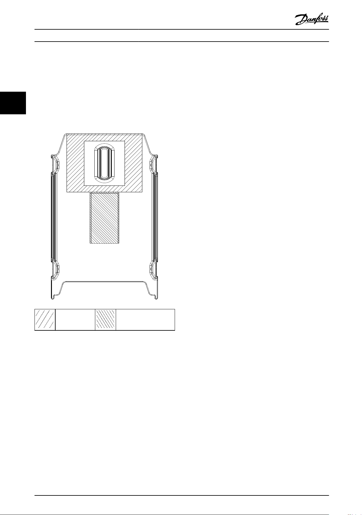
3.3.3 Prepare Adapter Plate
The adapter plate is available with or without pre-drilled
holes.
33
For adapter plate with no pre-drilled holes, refer to
Illustration 3.3.
When the adapter plate has no holes, drill them as follows:
4 holes within area 1, for fastening adapter plate
•
to motor (required).
1 hole within area 2, for a lifting lug (optional).
•
Make allowance for countersunk screws.
•
For adapter plate with pre-drilled holes, no extra holes are
required. Pre-drilled holes are specic for FCM 106 motors
only.
Area 1 Area 2
Illustration 3.3 Adapter Plate, Guide for Drilling Holes
14 Danfoss A/S © 11/2015 All rights reserved. MG03L302
Page 17
195NA411.12
Mechanical Installation Operating Instructions
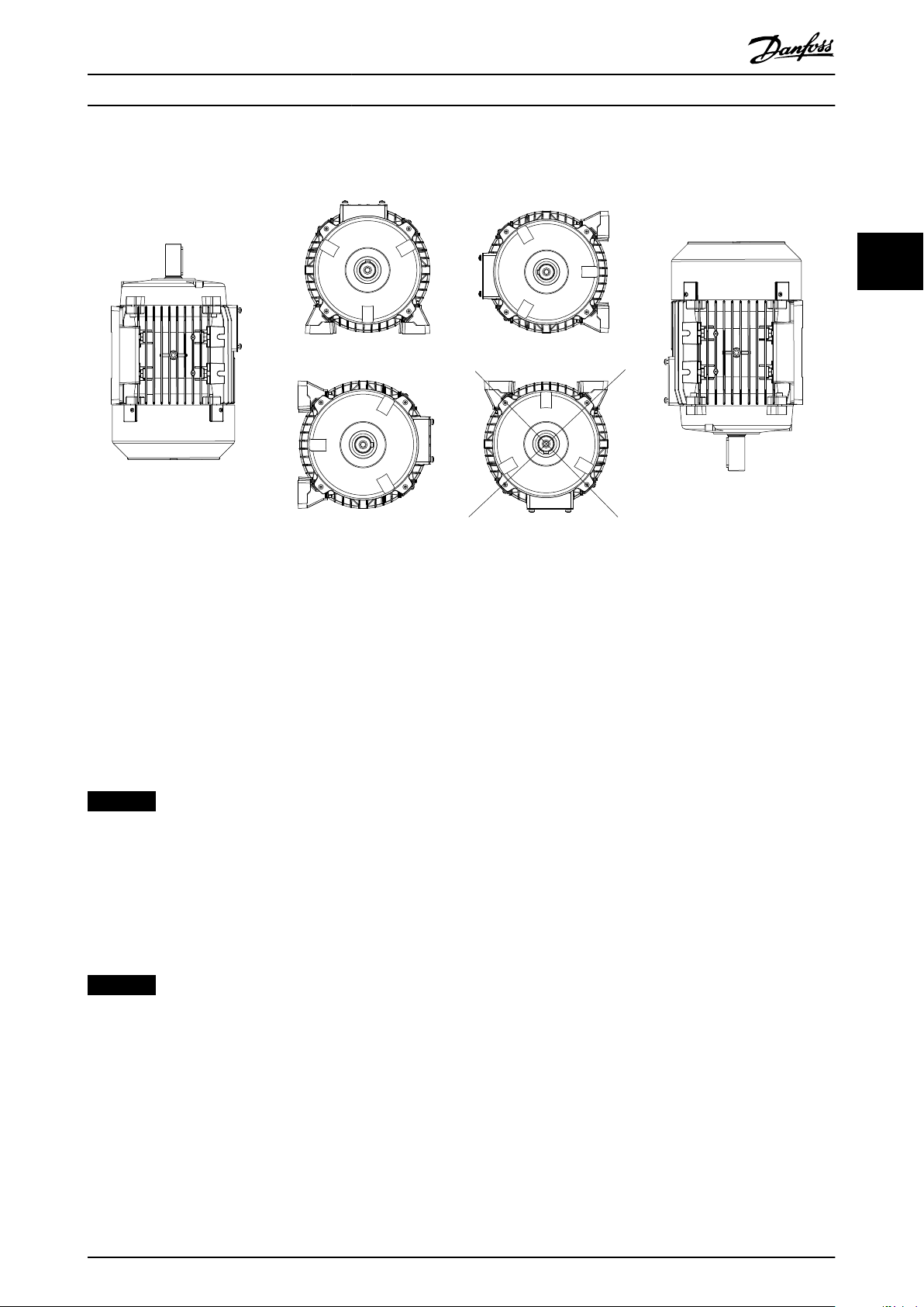
3.3.4 Mount the DriveMotor
3 3
Illustration 3.4 Installation Orientation, IP54/UL Type 3R
Mount the DriveMotor with adequate access for routine
maintenance. Observe the recommended clearances, see
chapter 7 Specications. A minimum of 0.75 m clearance
around the motor is recommended, both for working
access and adequate airow at the motor fan inlet. See
also chapter 7.1 Clearances, Dimensions and Weights.
Where more than 1 DriveMotor are mounted close by,
ensure that there is no recirculation of exhausted warm air.
Foundations must be solid, rigid, and level.
NOTICE
Electrical installation
Do not remove the top foil on the frequency converter,
as this foil is a part of the protective arrangements.
Fitting pinions, pulleys, and couplings
Drill pinions, pulleys, and couplings to standard limits and
t on the shaft with a screwing motion. Ensure correct
guarding of all moving parts.
NOTICE
Tapping of ttings onto the motor shaft, with a hammer
or mallet, causes bearing damage. This damage results in
an increase in bearing noise and a signicant reduction
in bearing life.
3.3.5 Shaft Alignment
When the application requires direct coupling, the shafts
must be correctly aligned in all 3 planes. Incorrect
alignment can be a major source of noise, vibration, and
reduced bearing life.
Make allowance for shaft end
in both axial and vertical planes. Flexible drive couplings
are preferred.
oat and thermal expansion
MG03L302 Danfoss A/S © 11/2015 All rights reserved. 15
Page 18
Mechanical Installation VLT® DriveMotor FCP 106/FCM 106
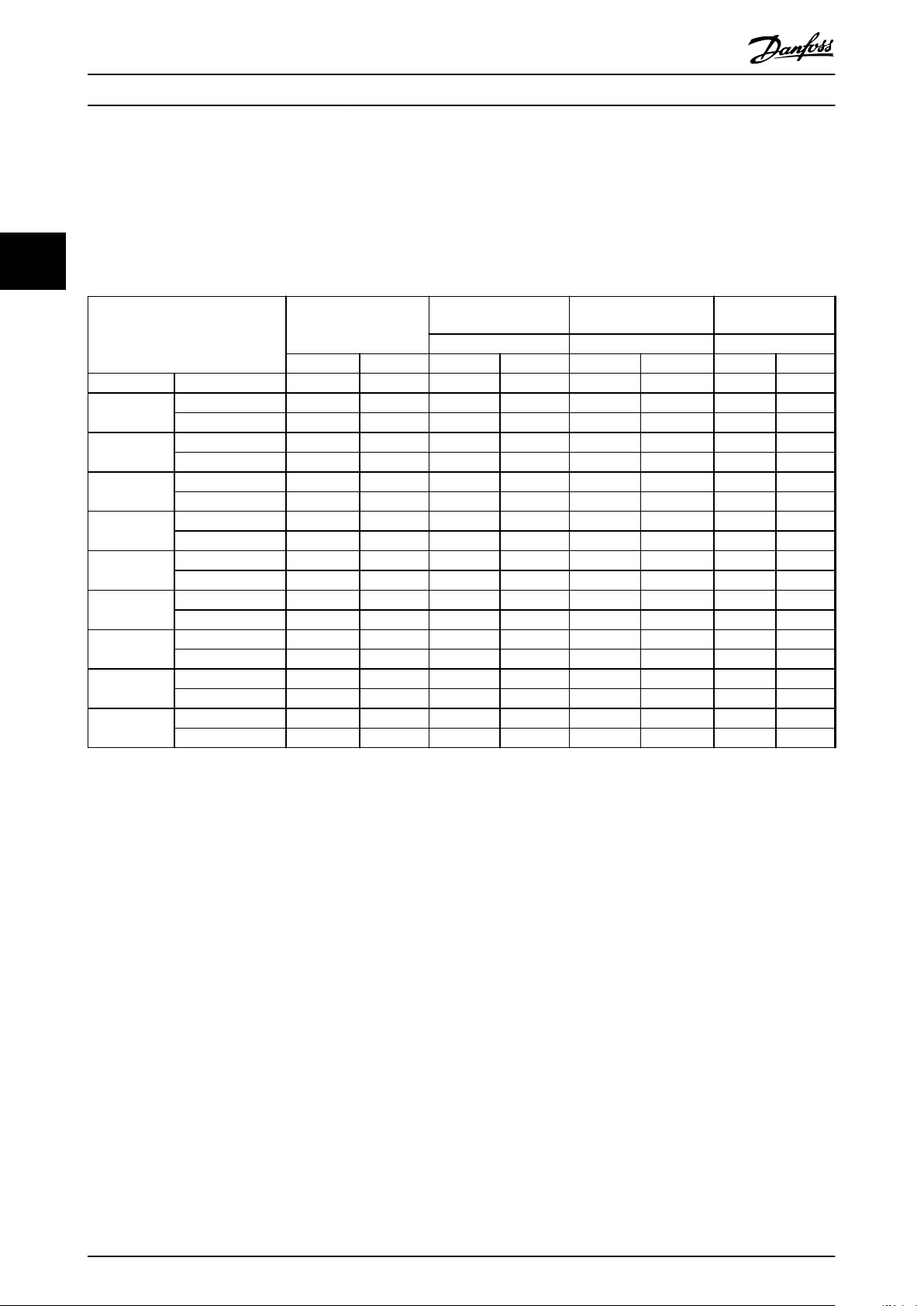
3.3.6 Bearing Life and Lubrication
The life expectancy of the ball bearings is according to Table 3.1 and Table 3.2, when the following conditions are fullled:
Temperature of 80 °C (176 °F).
•
Radial forces in load point corresponding to half-shaft extension do not exceed the values specied in Table 3.1
•
33
and Table 3.2.
Permissible radial forces Permissible axial forces
IE2 50 Hz 3-phase motors
20000 h 40000 h 20000 h 40000 h 20000 h 40000 h 20000 h 40000 h
Motor size Number of poles F rad [N] F rad [N] F ax [N] F ax [N] F ax [N] F ax [N] F ax [N] F ax [N]
71
80
90
100
112
132 S
132 M
160 M
160 L
2 460 370 230 175 260 205 210 170
4 580 465 330 250 350 275 300 240
2 590 475 320 255 340 280 290 220
4 830 665 440 350 470 380 410 310
2 670 535 340 260 380 315 310 235
4 940 750 480 365 470 385 440 330
2 920 735 480 360 540 460 430 325
4 1290 1030 680 530 740 620 620 465
2 930 745 480 380 560 475 400 300
4 1300 1040 680 540 750 630 600 450
2 1350 1080 800 625 1000 845 610 460
4 1900 1520 1130 880 1320 1095 930 700
2 1400 1120 780 610 990 835 580 435
4 1970 1575 1090 850 1300 1080 890 670
2 1550 1240 840 685 1180 975 500 395
4 2170 1735 1180 950 1520 1245 830 640
2 1580 1265 820 675 1180 980 460 365
4 2220 1775 1150 925 1510 1245 790 610
(IMB3)
Both directions Force upwards Force downwards
Permissible axial forces
(IMV1)
Permissible axial
forces (IMV1)
Table 3.1 Permissible Forces, IE2 50 Hz 3-phase Motors
Permissible radial forces: Load point corresponding to half-shaft extension, 0 axial force assumed.
Permissible axial forces: 0 radial force assumed.
Permissible loads of simultaneous radial and axial forces can be supplied on request.
16 Danfoss A/S © 11/2015 All rights reserved. MG03L302
Page 19
Mechanical Installation Operating Instructions
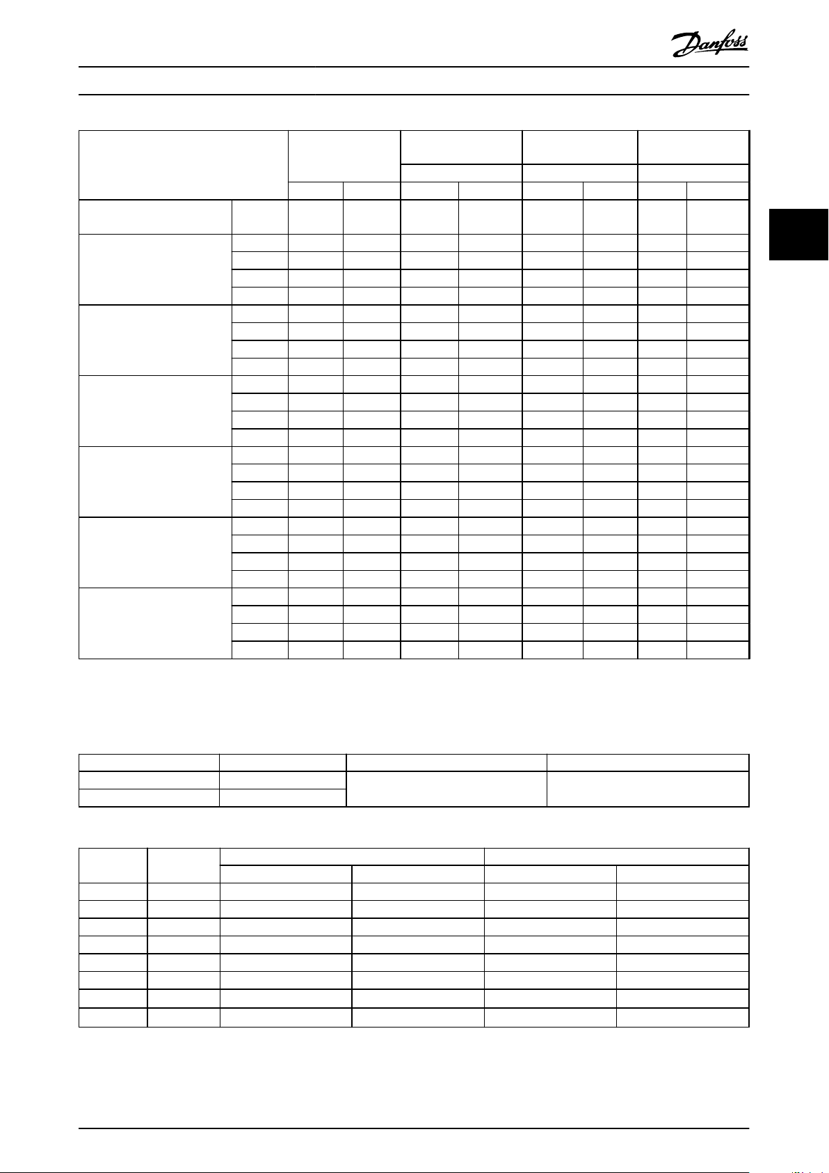
HPS motors
Motor size
71
90
112
132 M
132 XL
132 XXL
Permissible radial
forces
20000 h 40000 h 20000 h 40000 h 20000 h 40000 h 20000 h 40000 h
Speed
[RPM]
1500 580 465 330 250 350 275 300 240
1800 520 420 295 225 315 250 270 215
3000 460 370 230 175 260 205 210 170
3600 415 335 205 155 235 185 190 150
1500 940 750 480 365 470 385 440 330
1800 845 675 430 330 420 345 395 300
3000 670 535 340 260 380 315 310 235
3600 600 480 305 235 340 285 280 210
1500 1300 1040 680 540 750 630 600 450
1800 1170 935 610 485 675 565 540 405
3000 930 745 480 380 560 475 400 300
3600 835 670 430 340 505 430 360 270
1500 – – – – – – – –
1800 1710 1370 1015 790 1190 985 835 630
3000 1350 1080 800 625 1000 845 610 460
3600 1215 970 720 565 900 760 550 415
1500 1970 1575 1090 850 1300 1080 890 670
1800 – – – – – – – –
3000 1400 1120 780 610 990 835 580 435
3600 1260 1010 700 550 890 750 520 390
1500 1970 1575 1090 850 1300 1080 890 670
1800 1770 1415 980 765 1170 970 800 600
3000 1400 1120 780 610 990 835 580 435
3600 1260 1010 700 550 890 750 520 390
F rad [N] F rad [N] F ax [N] F ax [N] F ax [N] F ax [N] F ax [N] F ax [N]
Permissible axial forces
(IMB3)
Both directions Force upwards Force downwards
Permissible axial
forces (IMV1)
Permissible axial
forces (IMV1)
3 3
Table 3.2 Permissible Forces, HPS Motors
Permissible radial forces: Load point corresponding to half-shaft extension, 0 axial force assumed.
Permissible axial forces: 0 radial force assumed.
Permissible loads of simultaneous radial and axial forces can be supplied on request.
Motor type Motor frame size Lubrication type Temperature range
Asynchronous 80–180
PM 71–160
Table 3.3 Lubrication
Motor frame
size
71 1500/3000 – – 6205 2ZC3 6303 2ZC3
80 1500/3000 6204 2ZC3 6204 2ZC3 – –
90 1500/3000 6205 2ZC3 6205 2ZC3 6206 2ZC3 6205 2ZC3
100 1500/3000 6206 2ZC3 6206 2ZC3 – –
112 1500/3000 6306 2ZC3 6306 2ZC3 6208 2ZC3 6306 2ZC3
132 1500/3000 6208 2ZC3 6208 2ZC3 6309 2ZC3 6208 2ZC3
160 1500/3000
180 1500/3000
Table 3.4 Standard Bearing References and Oil Seals for Motors
1) Data available at future release.
Speed
[RPM]
Bearing type, asynchronous motors Bearing type, PM motors
Drive end Non-drive end Drive end Non-drive end
1) 1)
1) 1)
Lithium basis
-40 to +140 °C (-40 to +280 °F)
– –
– –
MG03L302 Danfoss A/S © 11/2015 All rights reserved. 17
Page 20

195NA516.10
1
Electrical Installation VLT® DriveMotor FCP 106/FCM 106
4 Electrical Installation
4.1 Safety Instructions
See chapter 2 Safety for general safety instructions.
44
WARNING
INDUCED VOLTAGE
Induced voltage from output motor cables that run
together can charge equipment capacitors, even with the
equipment turned o and locked out. Failure to run
output motor cables separately or use screened cables
could result in death or serious injury.
Run output motor cables separately, or
•
Use screened cables.
•
CAUTION
1 PCB area
SHOCK HAZARD
The frequency converter can cause a DC current in the
PE conductor. Failure to follow the recommendation
means that the RCD may not provide the intended
protection.
When a residual current-operated protective
•
device (RCD) is used for protection against
electrical shock, only an RCD of Type B is
permitted on the supply side.
CAUTION
EQUIPMENT HAZARD
The PCB area is sensitive to electrostatic discharge.
Touching the PCB area can cause equipment damage.
Do not touch the PCB area.
•
Illustration 4.1 Avoid Touching the PCB Area
Overcurrent protection
Extra protective equipment, such as short-circuit
•
protection or motor thermal protection between
frequency converter and motor, is required for
applications with multiple motors.
Input fusing is required to provide short-circuit
•
and overcurrent protection. If not factorysupplied, the installer must provide fuses. See
maximum fuse ratings in Table 7.15, Table 7.16,
and Table 7.17.
Wire type and ratings
NOTICE
Insulation requirements, MH1
For control card and relay card wires, the minimum
required insulation is 300 V and 75 °C (167 °F).
All wiring must comply with local and national
•
regulations regarding cross-section and ambient
temperature requirements.
Power connection wire recommendation:
•
Minimum 75 °C (167 °F) rated copper wire.
See chapter 7 Specications and chapter 7.6 Cable Speci-
cations for recommended wire sizes and types.
18 Danfoss A/S © 11/2015 All rights reserved. MG03L302
Page 21

195NA403.11
1
Electrical Installation Operating Instructions
4.2 IT Mains
CAUTION
IT MAINS
Installation on isolated mains source, that is, IT mains.
Maximum supply voltage allowed when connected to
mains: 440 V (3x380–480 V units).
For IT mains operation only:
Disconnect power and wait until discharged. See
•
discharge time in Table 2.1.
Remove cover, see Illustration 4.7.
•
Disable the RFI lter by removing the RFI switch/
•
screw. For location, see Illustration 4.2.
In this mode, the internal RFI lter capacitors between
housing and the mains RFI lter circuit are disabled, to
reduce the ground capacity currents.
4 4
1 RFI switch/screw
Illustration 4.2 Location of RFI Switch/Screw
CAUTION
To reinsert, use an M3.5x20 screw only.
MG03L302 Danfoss A/S © 11/2015 All rights reserved. 19
Page 22

195NA420.10
L1
L2
L3
PE
7
1
2
3
4
56
Electrical Installation VLT® DriveMotor FCP 106/FCM 106
4.3 EMC-compliant Installation
4.3.1 EMC-compliant Electrical Installation
44
1 PLC 5 Control cables
2 Motor 6 Mains, 3-phase, and reinforced PE
3 Frequency converter 7 Cable insulation (stripped)
4 Minimum 200 mm (7.87 in) clearance between control cable, mains cable, and mains motor cable.
Illustration 4.3 EMC-compliant Electrical Installation, FCP 106
20 Danfoss A/S © 11/2015 All rights reserved. MG03L302
Page 23

195NA407.10
L1
L2
L3
PE
1
6
2
5 4
3
Electrical Installation Operating Instructions
4 4
1 PLC 4 Control cables
2 DriveMotor 5 Mains, 3-phase, and reinforced PE
3 Minimum 200 mm (7.87 in) clearance between control
cable and mains cable.
6 Cable insulation (stripped)
Illustration 4.4 EMC-compliant Electrical Installation, FCM 106
MG03L302 Danfoss A/S © 11/2015 All rights reserved. 21
Page 24

Electrical Installation VLT® DriveMotor FCP 106/FCM 106
To ensure EMC-compliant electrical installation, observe
these general points:
Use only screened motor cables and screened
•
control cables.
Connect the screen to ground at both ends.
•
Avoid installation with twisted screen ends
•
(pigtails), since this type of installation ruins the
44
screen eect at high frequencies. Use the cable
clamps provided instead.
Ensure the same potential between frequency
•
converter and ground potential of the PLC.
Use star washers and galvanically conductive
•
installation plates.
4.4 Cable Requirements
All cabling must comply with national and local regulations
on cable cross-sections and ambient temperature. Copper
or aluminium conductors are required (75 °C (167 °F)
(recommended). For cable specications, refer to
chapter 7.6 Cable Specications.
Grounding
4.5
When connecting the FCP 106 to a third-party motor,
ensure protective bonding:
Ensure metal contact between the frequency
•
converter and the motor, see Illustration 4.5.
Mount an extra ground wire on the adapter plate.
•
Mount an extra ground wire on the motor.
•
Motor Connection
4.6
Step Description
1 Mount motor phases and thermistor wires in crimp
terminals.
Crimp ordering numbers (AMP standard power timer
contacts)1):
134B0495 (0.2–0.5 mm2) [AWG 24–20].
•
134B0496 (0.5–1 mm2) [AWG 20–17].
•
134B0497 (1–2.5 mm2) [AWG 17–13.5].
•
134B0498 (2.5–4 mm2) [AWG 13–11].
•
134B0499 (4–6 mm2) [AWG 12-10].
•
2 Mount PE clamp to motor connector and connect crimp
PE terminal to wire.
3 Mount the gasket between the motor and adapter plate.
See chapter 3.3.2 Prepare Gasket.
4 Pull motor phases and thermistor wires through the neck
of the adapter plate.
5 Mount the adapter plate onto the motor using 4 screws.
Insert guide pins into 2 of the screw holes, before
•
lowering the adapter plate into position. Remove the
guide pins when mounting screws.
Ensure that metallic contact is established between
•
the adapter plate and the motor, via the screws.
6 Mount motor connector gaskets onto the neck of the
adapter plate.
7 Click the terminals into the motor connector.
Mount the 3 motor phases.
•
Mount the 2 thermistor wires.
•
Mount PE connector.
•
For correct installation, refer to terminal numbers
•
printed on the motor connector.
NOTICE
4.6.1 Connect FCP 106 to Motor
NOTICE
To avoid damage to equipment, before mounting the
FCP 106 on the motor:
Observe cooling clearances specied in
•
Table 7.1.
Observe screw clearances listed in Table 7.2.
•
NOTICE
RISK OF DAMAGE
Screws extending too far into the enclosure or too far
above the adapter plate pose a risk of damage to motor
or frequency converter.
The thermistor is not galvanically isolated.
Interchanging the thermistor wires with the motor
wires may permanently damage the frequency
converter.
8 Click motor connector into the neck of the adapter plate.
9 Position the FCP 106 on adapter plate.
10 Fasten the FCP 106 to adapter plate using 4 screws.
Table 4.1 Installation Steps as Shown in Illustration 4.5
1) Contacts from other manufacturers, and contacts made with equal
or better electrical conductivity and plating, are also suitable if they
full the mechanical and electrical requirements.
The FCP 106 is now mounted onto the motor. The
combined unit is known as the DriveMotor.
To connect the FCP 106 to the motor, follow the installation steps shown in Table 4.1 and Illustration 4.5.
22 Danfoss A/S © 11/2015 All rights reserved. MG03L302
Page 25

195NA415.11
6
9
1
10
8
5
4
3
T1
M
M
T2
U
V
W
PE
2
7
Electrical Installation Operating Instructions
4 4
1 U, V, W (motor phases) 6 Adapter plate
2 MT1, MT2 (motor thermistor wires) 7 Motor connector gasket
3 PE 8 Motor connector
4 Gasket between motor and motor bracket 9 Frequency converter
5 Motor cables 10 Fastening screw
Illustration 4.5 Connecting FCP 106 to Motor
MG03L302 Danfoss A/S © 11/2015 All rights reserved. 23
Page 26

1
2
3
4
195NA413.10
195NA408.11
Electrical Installation VLT® DriveMotor FCP 106/FCM 106
4.6.2 Thermistor Input from Motor
Connect the motor thermistor to the terminals located in
the motor connector, as shown in chapter 4.6.1 Connect FCP
106 to Motor.
Set parameter 1-90 Motor Thermal Protection according to
guidelines in chapter 5.4.5 Thermistor Set-up. For more
®
44
detailed information, refer to the VLT
and FCM 106 Programming Guide.
DriveMotor FCP 106
NOTICE
The thermistor is not galvanically isolated. Interchanging
the thermistor wires with the motor wires may
permanently damage the frequency converter.
4.7 AC Mains Connection
4.7.1 Connecting to Mains
The frequency converter is designed to operate all
standard 3-phased asynchronous motors and PM motors.
For maximum cross-section on wires, see
chapter 7.2.1 Mains Supply 3x380–480 V AC Normal and High
Overload.
FCP 106 wall mount
To comply with EMC emissions requirements:
•
- Use screened motor cable, maximum
length 0.5 m (1.64 ft).
- Connect this cable to the metal housing
of both the frequency converter and the
motor.
See also chapter 4.3 EMC-compliant Installation.
•
Procedure for connection of mains power
1. Observe safety precautions, see chapter 2.2 Safety
Precautions.
2. Loosen front cover screws.
3. Remove the front cover, see Illustration 4.7.
4. Mount cable glands fullling the requirements for
the needed enclosure integrity.
5. Connect the ground wires to the ground
terminals via the cable glands, see Illustration 4.8.
6. Connect the mains cable to terminals L1, L2, and
L3, and tighten the screws. See Illustration 4.8.
7. Reassemble cover and tighten screws.
8. For tightening torques, see chapter 7.8 Connection
Tightening Torques.
1 LCP extension cable entry
2, 3 Entries for other cables: Control, RS485, and relay
cables
4 Mains cable entry
Illustration 4.6 Location of Cable Entries, MH1–MH3
Illustration 4.7 Remove Front Cover
24 Danfoss A/S © 11/2015 All rights reserved. MG03L302
Page 27

195NA405.12
5 6
1
2
3
4
195NA458.12
5
7
1
2
4
3
6
Electrical Installation Operating Instructions
1 Control terminals
2 Relays
3 Mains (L3, L2, L1)
4 PE
5 RS485
6 Spring clamp for PROFIBUS cable
Control Wiring
4.8
4.8.1 Control Terminals and Relays 2
Procedure:
1. Connect the terminal and cables at the locations
shown in Illustration 4.9 and Illustration 4.10.
2. For more terminal details, refer to
chapter 4.8.2 Control Terminals and Relays 3.
3. Mount the front cover and tighten the screws.
4. The frequency converter is now ready. For startup, go to chapter 5.1.2 Start-up.
4.8.2 Control Terminals and Relays 3
4 4
Illustration 4.8 Cabling, MH1–MH3
1 Control terminals
2 Relay terminals
3 UDC+, UDC-, Line (L3, L2, L1)
4 PE
5 LCP connector
6
7
Illustration 4.9 Location of Terminals and Relays, MH1
VLT® PROFIBUS DP MCA 101
VLT® Memory Module MCM 101
MG03L302 Danfoss A/S © 11/2015 All rights reserved. 25
Page 28

195NA409.12
1
2
3
4
8
5
6
7
130BB625.11
12 20 55
202729 42 45 55
50 53 54
GND
GND
DIGI IN/OUT
DIGI IN/OUT
61 68 69
N
P
COMM. GND
+24 V
DIGI IN
DIGI IN
10 V/20 mA IN
10 V/20 mA IN
0/4-20m A A OUT/DIG OUT
0/4-20 mA A OUT/DIG OUT
10 V OUT
BUS TER.
OFF ON
Electrical Installation VLT® DriveMotor FCP 106/FCM 106
Terminal
number
12 +24 V output – –
18 Digital input *PNP/NPN Start
19 Digital input *PNP/NPN No operation
20 Com – –
27 Digital input/
29 Digital input/
44
50 +10 V output – –
53 Analog input *0–10 V/0–20 mA/
54 Analog input *0–10 V/0–20 mA/
1 Control terminals
2 Relay terminals
3 UDC+, UDC-, Line (L3, L2, L1)
4 PE
5 LCP connector
6
7
8 Spring clamp for PROFIBUS cable
VLT® PROFIBUS DP MCA 101
VLT® Memory Module MCM 101
55 Com – –
42 10 bit *0–20 mA/4–20 mA/DO Analog
45 10 bit *0–20 mA/4–20 mA/DO Analog
1, 2, 3 Relay 1 1, 2 NO 1, 3 NC [9] Alarm
4, 5, 6 Relay 2 4, 5 NO 4, 6 NC [5] Drive
Table 4.2 Control Terminal Functions
* Indicates default setting.
Function Conguration Factory
setting
*PNP/NPN Coast inverse
output
*PNP/NPN Jog
output/pulse
input
Ref1
4–20 mA
Ref2
4–20 mA
running
Illustration 4.10 Location of Terminals and Relays, MH2–MH3
Control terminals
Illustration 4.11 Control Terminals
NOTICE
PNP/NPN is common for terminals 18, 19, 27, and 29.
4.8.3 Load Sharing
Load sharing is not allowed.
4.8.4 Brake
The frequency converter has no internal brake. An external
brake can be connected between the UDC+ and UDCterminals. Limit the voltage between these terminals to
maximum 768 V.
NOTICE
Increasing voltage beyond the limit decreases life, and
may permanently damage the frequency converter.
26 Danfoss A/S © 11/2015 All rights reserved. MG03L302
Page 29

Electrical Installation Operating Instructions
4.9 Installation Checklist
Before completing installation of the unit, inspect the entire installation as detailed in Table 4.3. Check and mark the items
when completed.
Inspect for Description
Auxiliary equipment•Look for auxiliary equipment, switches, disconnects, or input fuses/circuit breakers, residing on the input
power side of the frequency converter, or output side to the motor. Ensure that they are ready for full-
speed operation.
Check the function and installation of any sensors used for feedback to the frequency converter.
•
Remove any power factor correction caps on the motor.
•
Adjust any power factor correction caps on the mains side and ensure that they are dampened.
•
Cable routing
Control wiring
Cooling clearance
Ambient conditions•Check that requirements for ambient conditions are met.
Fusing and circuit
breakers
Grounding
Input and output
power wiring
Panel interior
Switches
Vibration
Ensure that the motor wiring and control wiring are separated, screened, or in 3 separate metallic conduits
•
for high frequency interference isolation.
Check for broken or damaged wires and loose connections.
•
Check that the control wiring is isolated from power and motor wiring for noise immunity.
•
Check the voltage source of the signals, if necessary.
•
The use of screened cable or twisted pair is recommended. Ensure that the screen is terminated correctly.
Ensure that the top and bottom clearance is adequate to ensure proper air ow for cooling, see
•
chapter 7.1 Clearances, Dimensions and Weights.
Check for proper fusing or circuit breakers.
•
Check that all fuses are inserted rmly and are in operational condition, and that all circuit breakers are in
•
the open position.
Check for sucient ground connections and ensure that those connections are tight and free of oxidation.
•
Grounding to conduit, or mounting the back panel to a metal surface, is not a suitable grounding.
•
Check for loose connections.
•
Check that the motor and mains cables are in separate conduit or separated screened cables.
•
Inspect that the unit interior is free of dirt, metal chips, moisture, and corrosion.
•
Check that the unit is mounted on an unpainted, metal surface.
•
Ensure that all switch and disconnect settings are in the proper positions.
•
Check that the unit is mounted solidly, or that shock mounts are used, as necessary.
•
Check for an unusual amount of vibration.
•
☑
4 4
Table 4.3 Installation Check List
CAUTION
POTENTIAL HAZARD IN THE EVENT OF INTERNAL FAILURE
Risk of personal injury if the frequency converter is not properly closed.
Before applying power, ensure that all safety covers are in place and securely fastened.
•
MG03L302 Danfoss A/S © 11/2015 All rights reserved. 27
Page 30

Electrical Installation VLT® DriveMotor FCP 106/FCM 106
4.9.1 Recommendations for UL-listed PRGY
Systems
WARNING
FIRE HAZARD
For VLT® DriveMotor FCM 106 with either asynchronous
or permanent magnet motors listed under UL PRGY
systems, conduct a locked rotor temperature test and a
44
running overload test to avoid motor overtemperature.
The need for conducting the tests is determined by the
end product standard where the VLT® DriveMotor FCM
106 is used. Failure to complete/pass the locked rotor
temperature test and the running overload test could
prevent the frequency converter from functioning.
Check and set the following parameters before
•
test:
- Parameter 1-90 Motor Thermal
Protection.
- Parameter 4-18 Current Limit.
- Parameter 14-20 Reset Mode.
- Parameter 14-21 Automatic Restart
Time.
- Parameter 14-90 Fault Level.
- Parameter 30-22 Locked Rotor Detection.
Do not exceed the temperature limits stated in
•
the motor data provided by the motor
manufacturer.
28 Danfoss A/S © 11/2015 All rights reserved. MG03L302
Page 31

130BB628.10
Select Language
[ 0 ] English
Setup 1
130BD512.10
Auto
on
Reset
Hand
on
O
Status
Quick
Menu
Main
Menu
Alarm
Log
Back
Cancel
Info
OK
Status
1(1)
0.00 kW
O Remote Stop
0.0Hz
On
Alarm
Warn.
A
0.00 A
0.0 %
B
C
D
2605 kWh
1
2
3
4
5
6
7
8
9
10
11
12
13
14
15
16
17
18 19 20 21
Commissioning Operating Instructions
5 Commissioning
5.1 Applying Power
5.1.1 Turn on Mains Power
Turn on mains power to power up the frequency converter.
5.1.2 Start-up
Start the frequency converter.
5 5
At the rst power-up with LCP connected, select the
preferred language. Once selected, this screen does not
appear again in the following power-ups. To change
language at a later stage, go to parameter 0-01 Language.
Illustration 5.1 Select Language
5.2 Local Control Panel Operation
NOTICE
The frequency converter can also be programmed from a
PC via the RS485 COM port by installing the MCT 10 Setup Software.
The LCP is divided into 4 functional sections.
A. Alphanumeric display.
B. Menu selection.
D. Operation keys and indicator lights (LEDs).
C. Navigation keys and indicator lights (LEDs).
Illustration 5.2 Local Control Panel (LCP)
A. Display area
The display area is activated when the frequency converter
receives power from mains voltage, a DC bus terminal, or a
24 V DC external supply.
The information shown on the LCP can be customized for
user application. Select options in the Quick Menu Q3-13
Display settings.
Call-
Display Parameter
out
1 1.1 0-20 Reference %
2 1.2 0-21 Motor current
3 1.3 0-22 Power [kW ]
4 2 0-23 Frequency
5 3 0-24 kWh counter
number
Default setting
Table 5.1 Legend to Illustration 5.2
MG03L302 Danfoss A/S © 11/2015 All rights reserved. 29
Page 32

195NA422.11
1
2
42 mm
Commissioning VLT® DriveMotor FCP 106/FCM 106
B. Display menu key
Menu keys are used for menu access for parameter set-up,
D. Operation keys and indicator lights (LEDs)
Operation keys are at the bottom of the LCP.
toggling through status display modes during normal
operation, and viewing fault log data.
Callout Key Function
6 Status Shows operational information.
7 Quick Menu Allows access to programming
parameters for initial set-up
instructions and many detailed
application instructions.
8 Main Menu Allows access to all programming
55
9 Alarm Log Shows a list of current warnings,
Table 5.2 Legend to Illustration 5.2
parameters.
the last 10 alarms, and the
maintenance log.
Callout Key Function
18 Hand On Starts the frequency converter in local
control.
An external stop signal by control
•
input or serial communication
overrides the local hand on.
19 O Stops the motor but does not remove
power to the frequency converter.
20 Auto On Puts the system in remote operational
mode.
Responds to an external start
•
command by control terminals or
serial communication.
21 Reset Resets the frequency converter manually
after a fault has been cleared.
C. Navigation keys and indicator lights (LEDs)
Navigation keys are used for programming functions and
Table 5.5 Legend to Illustration 5.2
moving the display cursor. The navigation keys also
provide speed control in local operation. There are also 3
frequency converter status indicator lights in this area.
NOTICE
To adjust the display contrast, press [Status] and [▲]/[▼].
Callout Key Function
10 Back Reverts to the previous step or list in
the menu structure.
11 Cancel Cancels the last change or command
as long as the display mode has not
changed.
12 Info Press for a denition of the function
shown.
13 Navigation keys Press to move between items in the
menu.
14 OK Press to access parameter groups or
to enable a selection.
Table 5.3 Legend to Illustration 5.2
Call-
out
15 ON Green The ON light activates when the
16 WARN Yellow When warning conditions are
17 ALARM Red A fault condition causes the red
Indicator Light Function
frequency converter receives
power from mains voltage, a DC
bus terminal, or a 24 V external
supply.
met, the yellow WARN light
turns on, and text appears in
the display area identifying the
problem.
alarm light to ash, and an
alarm text is shown.
Table 5.4 Legend to Illustration 5.2
5.2.1 Connect LCP Cable
1 Control panel
2 Panel door
Illustration 5.3 LCP Remote Mounting
To view or change the frequency converter settings, attach
the LCP using the LCP cable. See Illustration 5.3.
After use, remove the LCP cable from the frequency
converter to maintain the ingress protection class of the
enclosure.
30 Danfoss A/S © 11/2015 All rights reserved. MG03L302
Page 33

195NA501.10
1
Commissioning Operating Instructions
5.3 Memory Module MCM 101
The VLT® Memory Module MCM 101 is a small memory
plug containing data such as:
Firmware.
•
SIVP le.
•
Pump table.
•
Motor database.
•
Parameter lists.
•
The frequency converter comes with the module installed
from the factory.
5.3.1
Conguring with the VLT® Memory
Module MCM 101
When replacing or adding a frequency converter to a
system, it is easy to transfer existing data to the new
frequency converter. However, the frequency converters
must be of the same power size and with compatible
hardware.
WARNING
DISCONNECT POWER BEFORE SERVICING!
Before performing repair work, disconnect the frequency
converter from AC mains. After mains has been discon-
nected, wait 4 minutes for the capacitors to discharge.
Failure to follow these steps can result in death or
serious injury.
1. Remove the lid from a frequency converter
containing a memory module.
2. Unplug the memory module.
3. Place and tighten the lid.
4. Remove the lid from the new frequency
converter.
5. Insert the memory module in the new/other
frequency converter and leave it in.
6. Place and tighten the lid on the new frequency
converter.
7. Power up the frequency converter.
5 5
1
VLT® Memory Module MCM 101
Illustration 5.4 Location of Memory Module
If the memory module becomes defect, it does not prevent
the frequency converter from working. The warning LED
on the lid ashes, and a warning shows in the LCP (if
installed).
Warning 206, Memory module indicates that either a
frequency converter runs without a memory module, or
that the memory module is defect. To see the exact reason
for the warning, refer to parameter 18-51 Memory Module
Warning Reason.
A new memory module can be ordered as a spare part.
Ordering number: 134B0791.
NOTICE
The rst power-up takes approximately 3 minutes.
During this time, all data is transferred to the new
frequency converter.
5.4 Basic Programming
This manual explains initial set-up only. For full parameter
lists, refer to the VLT® DriveMotor FCP 106 and FCM 106
Programming Guide.
At initial start-up, the frequency converter enters the startup wizard for open-loop applications, see
chapter 5.4.1
Once the start-up wizard has completed, the following
extra set-up wizards and instructions are available:
•
•
•
For general instructions on how to change parameter
settings, refer to chapter 5.4.4 Changing Parameter Settings.
Conguration for Open-loop Applications.
Chapter 5.4.2 Set-up Wizard for Closed-loop
Applications.
Chapter 5.4.3 Quick Menu Motor Set-up.
Chapter 5.4.5 Thermistor Set-up.
MG03L302 Danfoss A/S © 11/2015 All rights reserved. 31
Page 34

FC
+24 V (OUT)
DIG IN
DIG IN
DIG IN
DIG IN
COM DIG IN
A OUT / D OUT
A OUT / D OUT
18
19
27
29
42
55
50
53
54
20
12
01
02
03
04
05
06
R2
R1
+
0–10 V
Start
+10 V (OUT)
A IN
A IN
COM IN/OUT
130BB674.11
45
Reference
Commissioning VLT® DriveMotor FCP 106/FCM 106
5.4.1 Conguration for Open-loop Applications
This section guides the installer through the set-up of the frequency converter in a clear and structured manner to set up
an open-loop application. An open-loop application does not utilize a feedback signal from the process.
55
Illustration 5.5 Principle Wiring for Open-loop Applications
32 Danfoss A/S © 11/2015 All rights reserved. MG03L302
Page 35

195NA416.11
International
4-12
Motor Speed low Limit
Hz
4-14
Motor Speed high Limit
Hz
3-41
Ramp 1 ramp-up time
s
3-42
Ramp 1 ramp-down Time
s
1-73 Active
Flying start?
Disable
1-20
Motor Power
1-22
Motor Voltage
1-23
Motor frequency
1-24
Motor current
1-25
Motor nominal speed
0-03
Regional Settings
380-440V/50Hz
Grid Type
Asynchronous motor
Asynchronous
1-10
Motor Type
1-24
Motor current
1-25
Motor nominal speed
1-26
Motor Cont. Rated Torque
1-30
Stator resistance
1-39
Motor poles
1-40
Back EMF at 1000 rpm
1-37
d-axis inductance
6 - 10 T53 low Voltage
V
6 - 11 T53 high Voltage
V
6 - 12 T53 Low Current
A
6 - 13 T53 High Current
A
Current
Voltage
AMA Failed
0.0 Hz
0.0 kW
Wizard completed
Press OK to accept
1-29
Automatic Motor Adaption
O
Auto Motor Adapt OK
Press OK
5 - 40 Function of Relay 2
No function
5 - 40 Function of Relay 1
[0] No function
3-03
Max Reference
Hz
3-02
Min Reference
Hz
AMA running
-----
AMA failed
Perform AMA
(Do not perform AMA)
AMA OK
6 - 19 T53 Mode
Current
3.8
A
3000
RPM
5.4
Nm
0.65
Ohms
8
57
V
5
mH
1.50
kW
0050
V
0050
Hz
04.66
A
1420
RPM
[0]
Motor type = Asynchronous
Motor type = PM motor
0000
0050
0003
0003
04.66
13.30
0050
0220
0000
0050
[12]
[0]
[0]
[0]
[0]
[1]
[0]
0-06
PM motor
1-38 q-axis Inductance (Lq)
5
mH
1-44 Current at Min Inductance for d-axis
100
%
Current at Min Inductance for q-axis
100
%
1-70 PM Start Mode
Rotor Detection
[0]
1-46 Position Detection Gain
%
O
100
30-22 Locked Rotor Detection
[0]
s
30-23 Locked Rotor Detection Time[s]
0.10
4-19 Max Output Frequency
65
Hz
Motor Type = IPM
IPM Type = Sat.
IPM Type = non-Sat.
Commissioning Operating Instructions
5 5
Illustration 5.6 Conguration for Open-loop Applications
MG03L302 Danfoss A/S © 11/2015 All rights reserved. 33
Page 36

6-29 Terminal 54 Mode
[1]
Voltage
6-25 T54 high Feedback
0050
Hz
20-94 PI integral time
0020.00
s
Current
Voltage
This dialog is set to
[1] Analog input 54
20-00 Feedback 1 source
[1]
Analog input 54
3-10 Preset reference [0]
0.00
3-03 Max Reference
50.00
3-02 Min Reference
0.00
Asynchronous Motor
1-73 Flying Start
[0]
No
1-22 Motor Voltage
400
V
1-24 Motor Current
04.66
A
1-25 Motor nominal speed
1420
RPM
3-41 Ramp 1 ramp-up time
0003
s
3-42 Ramp1 ramp-down time
0003
s
0-06 Grid Type
4-12 Motor speed low limit
0016
Hz
4-13 Motor speed high limit
0050
Hz
195NA417.11
1-20 Motor Power
1.10
kW
1-23 Motor Frequency
50
Hz
6-22 T54 Low Current
A
6-24 T54 low Feedback
0016
Hz
6-23 T54 high Current
13.30
A
6-25 T54 high Feedback
0050
0.01
s
20-81 PI Normal/Inverse Control
[0]
Normal
20-83 PI Normal/Inverse Control
0050
Hz
20-93 PI Proportional Gain
00.50
1-29 Automatic Motor Adaption
[0]
O
6-20 T54 low Voltage
0050
V
6-24 T54 low Feedback
0016
Hz
6-21 T54 high Voltage
0220
V
6-26
T54 Filter time const.
1-00 Conguration Mode
[3]
Closed Loop
0-03 Regional Settings
[0]
Power kW/50 Hz
3-16 Reference Source 2
[0]
No Operation
1-10 Motor Type
[0]
Asynchronous
[12]]
1-30 Stator Resistance
0.65
Ohms
1-25 Motor Nominal Speed
3000
RPM
1-24 Motor Current
3.8
A
1-26 Motor Cont. Rated Torque
5.4
Nm
1-38 q-axis inductance(Lq)
5
mH
4-19 Max Ouput Frequency
0065
Hz
1-40 Back EMF at 1000 RPM
57
V
PM Motor
1-39 Motor Poles
8
%
04.66
Hz
MotorType = Asynchronous
MotorType = PM Motor
Motor Type = IPM
IPM Type = Sat.
IPM Type = non-Sat.
1-44 d-axis Inductance Sat. (LdSat)
(1-70) PM Start Mode
Rotor Detection
[0]
1-46 Position Detection Gain
%
O
100
30-22 Locked Rotor Detection
[0]
s
30-23 Locked Rotor Detection Time[s]
0.10
5
mH
(1-45) q-axis Inductance Sat. (LqSat)
5
mH
(1-48) Current at Min Inductance for d-axis
100
%
1-49 Current at Min Inductance for q-axis
100
%
380-440V/50Hz
This dialog is set to
[0] No Operation
Commissioning VLT® DriveMotor FCP 106/FCM 106
5.4.2 Set-up Wizard for Closed-loop Applications
55
Illustration 5.7 Closed-loop Set-up Wizard
34 Danfoss A/S © 11/2015 All rights reserved. MG03L302
Page 37

Asynchronous Motor
1-73 Flying Start
[0]
No
1-22 Motor Voltage
400
V
1-24 Motor Current
04.66
A
1-25 Motor nominal speed
1420
RPM
3-41 Ramp 1 ramp-up time
0003
s
3-42 Ramp1 ramp-down time
0003
s
0-06 Grid Type
4-12 Motor speed low limit
0016
Hz
4-13 Motor speed high limit
0050
Hz
195NA462.11
1-20 Motor Power
1.10
kW
1-23 Motor Frequency
50
Hz
1-00
[3]
Closed Loop
0-03 Regional Settings
[0]
International
1-10 Motor Type
[0]
Asynchronous
[12]]
1-30 Stator Resistance
0.65
Ohms
1-25 Motor Nominal Speed
3000
RPM
1-24 Motor Current
3.8
A
1-26 Motor Cont. Rated Torque
5.4
Nm
1-38 q-axis inductance(Lq)
5
mH
4-19 Max Ouput Frequency
0065
Hz
1-40 Back EMF at 1000 RPM
57
V
PM Motor
1-39 Motor Poles
8
MotorType = Asynchronous
MotorType = PM Motor
Motor Type = IPM
IPM Type = Sat.
IPM Type = non-Sat.
1-44 d-axis Inductance Sat. (LdSat)
(1-70) PM Start Mode
Rotor Detection
[0]
1-46 Position Detection Gain
%
100
30-22 Locked Rotor Det ection
[0]
s
30-23 Locked Rotor Det ection Time[s]
0.10
5
mH
(1-45) q-axis Inductan ce Sat. (LqSat)
5
mH
(1-48) Current at Min Inductance for d-axis
100
%
1-49 Current at Min In ductance for q-axis
100
%
380-440V/50Hz
Commissioning Operating Instructions
5.4.3 Quick Menu Motor Set-up
The Quick Menu Motor Set-up guides the installer through setting of the required motor parameters.
NOTICE
MOTOR OVERLOAD PROTECTION
Thermal protection of the motor is recommended. Especially when running at low speed, the cooling from the
integrated motor fan is often not sucient.
Use PTC or Klixon, see chapter 4.6.2 Thermistor Input from Motor, or
•
Enable motor thermal protection by setting parameter 1-90 Motor Thermal Protection to [4] ETR trip 1.
•
5 5
Illustration 5.8 Quick Menu Motor Set-up
MG03L302 Danfoss A/S © 11/2015 All rights reserved. 35
Page 38

Commissioning VLT® DriveMotor FCP 106/FCM 106
5.4.4 Changing Parameter Settings
Quick access to change parameter settings:
1. To enter the Quick Menu, press [Menu] until the
indicator in the display reaches Quick Menu.
2.
Press [▲] [▼] to select wizard, closed-loop set-up,
motor set-up, or changes made, then press [OK].
3.
Press [▲] [▼] to browse through the parameters in
the Quick Menu.
4. To select a parameter, press [OK].
55
5.
Press [▲] [▼] to change the value of a parameter
setting.
6.
Press [►] to shift digit when a decimal parameter
is in the editing state.
7. To accept the change, press [OK].
8. Press either [Back] twice to enter Status, or press
[Menu] once to enter Main Menu.
The Main Menu accesses all parameters:
1. Press [Menu] until the indicator in the display
reaches Main Menu.
2.
Press [▲] [▼] to browse through the parameter
groups.
3. To select a parameter group, press [OK].
4.
Press [▲] [▼] to browse through the parameters in
the
specic group.
5. To select the parameter, press [OK].
6.
Press [▲] [▼] to set/change the parameter value.
Changes made:
1. Press [Menu] until the indicator in the display
reaches Quick Menu.
2.
Press [▲] [▼] to browse through the quick menus.
3. To select 05 Changes Made, press [OK].
Changes Made lists all parameters changed from
•
default settings.
The list shows only parameters which have been
•
changed in the current edit set-up.
Parameters which have been reset to default
•
values are not listed.
The message Empty indicates that no parameters
•
have been changed.
5.4.5 Thermistor Set-up
Set parameter 1-90 Motor Thermal Protection to [1]
Thermistor warning or [2] Thermistor trip. For details, refer to
VLT® DriveMotor FCP 106 and FCM 106 Programming Guide.
36 Danfoss A/S © 11/2015 All rights reserved. MG03L302
Page 39

Maintenance, Diagnostics an... Operating Instructions
6 Maintenance, Diagnostics and Troubleshooting
6.1 Maintenance
3. Disconnect the frequency converter from external
DC supply, if present.
Under normal operating conditions and load proles, the
frequency converter is maintenance-free throughout its
designed lifetime. To prevent breakdown, danger, and
damage, examine the frequency converter at regular
intervals depending on the operating conditions. Replace
worn or damaged parts with original spare parts or
standard parts. For service and support, contact the local
Danfoss supplier.
4. Disconnect the frequency converter from the
motor as it can generate voltage when turned, for
example by windmilling.
5. Wait for discharge of the DC link. For discharge
time, see Table 2.1.
6. Remove the frequency converter from the motor
adapter plate or wall mount plate.
1. Read the safety warnings in chapter 2 Safety.
2. Disconnect the frequency converter from mains.
6.2 List of Warnings and Alarms
Alarm/
warning
number
2 Live zero error X X
3 No motor X A motor has not been connected to the frequency converter.
4 Mains ph. loss X X X
7 DC over volt X X DC-link voltage exceeds limit.
8 DC under volt X X DC-link voltage is lower than voltage warning low-limit.
9
10 Motor ETR over X X
11 Motor th over X X
13 Over Current X X X Inverter peak current limit is exceeded.
14 Earth Fault X X X Discharge from output phases to ground.
16 Short Circuit X X Short circuit in motor or on motor terminals.
17
24 Fan fault X X External fans have failed either due to defect hardware, or due to
25 Brake resistor
27 Short circuited X X Brake chopper fault: The brake transistor is short-circuited, or the brake
28 Brake check X X Brake checked and failure detected.
Fault text Warning Alarm Trip lock Cause of problem
Signal on terminal 53 or 54 is less than 50% of value set in:
Parameter 6-10 Terminal 53 Low Voltage.
•
Parameter 6-12 Terminal 53 Low Current.
•
Parameter 6-20 Terminal 54 Low Voltage.
•
Parameter 6-22 Terminal 54 Low Current.
•
See also parameter group 6-0* Analog In/Out.
Missing phase on supply side or excess voltage imbalance. Check
supply voltage. See parameter 14-12 Function at Mains Imbalance.
Inverter
overload
Control word
timeout
short
X X More than 100% load for too long.
Motor is overheated due to more than 100% load for too long. See
parameter 1-90 Motor Thermal Protection.
Thermistor or thermistor connection is disconnected. See
parameter 1-90 Motor Thermal Protection.
X X
X X Brake resistor short-circuited: The brake resistor is monitored during
No communication to frequency converter. See parameter group 8-0*
Comm. and Options.
missing fans.
operation. If it short-circuits, the brake function is disconnected, and
the warning appears. Turn o the frequency converter and replace the
brake resistor.
function is disconnected. If short-circuited, substantial energy is
dissipated in the brake resistor. Turn o the frequency converter as a
re precaution.
6
6
MG03L302 Danfoss A/S © 11/2015 All rights reserved. 37
Page 40

6
Maintenance, Diagnostics an... VLT® DriveMotor FCP 106/FCM 106
Alarm/
warning
number
30 U phase loss X X
31 V phase loss X X
32 W phase loss X X
34 Fieldbus fault X
35 Option fault X
36 Mains failure X
38 Internal fault X X Contact the local Danfoss supplier.
40 Overload T27 X
41 Overload T29 X
44
46
47
51 AMA U
52 AMA low I
53
54
55
56
Fault text Warning Alarm Trip lock Cause of problem
Motor phase U is missing. Check the phase. See parameter 4-58 Missing
Motor Phase Function.
Motor phase V is missing. Check the phase. See parameter 4-58 Missing
Motor Phase Function.
Motor phase W is missing. Check the phase. See parameter 4-58 Missing
Motor Phase Function.
Earth fault
DESAT
Gate drive
voltage fault
Control voltage
fault
, I
nom
nom
nom
AMA motor too
big
AMA motor too
small
AMA parameter
out of range
AMA
interrupted by
user
X X
X X
X X X 24 V DC is possibly overloaded.
X
X The motor current is too low. Check the settings.
X The motor is too large to perform AMA.
X The motor is too small to perform AMA.
X
X The user has interrupted the AMA.
The setting of motor voltage, motor current, and motor power is
presumably wrong. Check the settings.
The parameter values found from the motor are outside acceptable
range.
Try to restart the AMA a number of times, until the AMA is complete.
NOTICE
57 AMA time-out X
Repeated runs can heat the motor to a level where the
resistance Rs and Rr are increased. In most cases, however,
this increased resistance is not critical.
58 AMA internal X X Contact the local Danfoss supplier.
59 Current limit X X The current is higher than the value in parameter 4-18 Current Limit.
External interlock has been activated. To resume normal operation,
60
63 Mech. brake
65 Ctr. card temp X X X
66
67 Option change X
69 Pwr. Card Temp X X X
38 Danfoss A/S © 11/2015 All rights reserved. MG03L302
External
Interlock
low
Heat sink
temperature
low
X
X
X
apply 24 V DC to the terminal programmed for external interlock and
reset the frequency converter. Reset via serial communication, digital
I/O, or [Reset] on the LCP).
The minimum required current for opening the mechanical brake has
not been reached.
The heat sink temperature is measured as 0 °C. This result could
indicate that the temperature sensor is defect. The defect causes the
fan speed to increase to its maximum to cool down the power part or
control card.
The temperature sensor on the power card is either too hot or too
cold.
Page 41

Maintenance, Diagnostics an... Operating Instructions
Alarm/
warning
number
70 Illegal FC cong X X Power size conguration fault on the power card.
80 Drive initialised X All parameter settings are initialised to default settings.
87
88
93 Dry pump X X
94 End of curve X X
95 Broken belt X X
99 Locked rotor X
101
126 Motor Rotating X High back EMF voltage. Stop the rotor of the PM motor.
127 Back EMF too
200 Fire Mode X Fire mode has been activated.
202
206
207
Fault text Warning Alarm Trip lock Cause of problem
Auto DC
Braking
Option
detection
Flow/pressure
info missing
high
Fire Mode
Limits Exceeded
Memory
module
Memory
module alarm
X The frequency converter is auto DC braking.
X X
Torque is below the torque level set for no load, indicating a broken
belt. See parameter group 22-6* Broken Belt Detection.
The frequency converter detected a locked rotor situation. See
parameter 30–22 Locked Rotor Protection and parameter 30–23 Locked
Rotor Detection Time [s].
X Flow/pressure information is missing.
X
X Fire mode has suppressed 1 or more warranty voiding alarms.
X
X X
6
6
Table 6.1 Warnings and Alarms
MG03L302 Danfoss A/S © 11/2015 All rights reserved. 39
Page 42

A
B
1 2
195NA494.10
Specications VLT® DriveMotor FCP 106/FCM 106
7 Specications
7.1 Clearances, Dimensions and Weights
7.1.1 Clearances
To ensure sucient air ow for the frequency converter, observe the minimum clearances listed in Table 7.1.
When air ow is obstructed close to the frequency converter, ensure adequate inlet of cool air and exhaust of hot air from
the unit.
Enclosure
Enclosure
size
MH1
MH2
77
MH3
Table 7.1 Minimum Clearance for Cooling
1) Power ratings relate to NO, see chapter 7.2 Electrical Data.
2) The stated IP and Type rating only apply when the FCP 106 is mounted on a wall mount plate or a motor with the adapter plate. Ensure that
the gasket between the adapter plate and the motor has a protection rating corresponding to the required rating for the combined motor and
frequency converter. As standalone frequency converter, the enclosure rating is IP00 and Open type.
Enclosure size Maximum depth of hole into adapter plate (A) [mm
Table 7.2 Details for Motor Adapter Plate Screws
IP66/Type 4X
IP66/Type 4X
IP66/Type 4X
MH1 3 (0.12) 0.5 (0.02)
MH2 4 (0.16) 0.5 (0.02)
MH3 3.5 (0.14) 0.5 (0.02)
Protection rating
FCP 106 FCM 106
2)
IP55/Type 12 0.55–1.5 (0.75–2.0) 30 (1.2) 100 (4.0)
2)
IP55/Type 12 2.2–4.0 (3.0–5.0) 40 (1.6) 100 (4.0)
2)
IP55/Type 12 5.5–7.5 (7.5–10) 50 (2.0) 100 (4.0)
(in)]
3x380–480 V Motor ange end Cooling fan end
Power
[kW (hp)]
1)
Maximum height of screw above adapter plate (B)
[mm (in)]
Clearance at ends
[mm (in)]
1 Adapter plate
2 Screw
A Maximum depth of hole into adapter plate
B Maximum height of screw above adapter plate
Illustration 7.1 Screws to Fasten Motor Adapter Plate
40 Danfoss A/S © 11/2015 All rights reserved. MG03L302
Page 43

195NA418.10
CC
B
A
a
X
Y
Specications Operating Instructions
7.1.2 FCP 106 Dimensions
Illustration 7.2 FCP 106 Dimensions
1)
Power
[kW (hp)]
Enclosure
type
3x380–480 V A a B C C X Y
MH1 0.55–1.5 (0.75–2.0) 231.4 (9.1) 130 (5.1) 162.1 (6.4) 106.8 (4.2) 121.4 (4.8) M20 M20 M6
MH2 2.2–4.0 (3.0–5.0) 276.8 (10.9) 166 (6.5) 187.1 (7.4) 113.2 (4.5) 127.8 (5.0) M20 M20 M6
MH3 5.5–7.5 (7.5–10) 321.7 (12.7) 211 (8.3) 221.1 (8.7) 123.4 (4.9) 138.1 (5.4) M20 M25 M6
Table 7.3 FCP 106 Dimensions
1) Power ratings relate to NO, see chapter 7.2 Electrical Data.
Length
[mm (in)]
Width
[mm (in)]
Height
[mm (in)]
Normal lid High lid for
VLT® PROFIBUS DP
MCA 101
option
Cable gland
diameter
7 7
Mounting
hole
MG03L302 Danfoss A/S © 11/2015 All rights reserved. 41
Page 44

195NA454.11
AB
A
AA
H
E
C
L
BB
B
BC
BA
K
AC
HD
ED1
ED
EB
Specications VLT® DriveMotor FCP 106/FCM 106
7.1.3 FCM 106 Dimensions
77
Motor frame size 71 80 90S 90L 100S 100L 112M 132S 132M
A [mm (in)] 112 (4.4) 125 (4.9) 140 (5.5) 140 (5.5) 160 (6.3) 160 (6.3) 190 (7.5) 216 (8.5) 216 (8.5)
B [mm (in)] 90 (3.5) 100 (4.0) 100 (4.0) 125 (4.9) 140 (5.5) 140 (5.5) 140 (5.5) 140 (5.5) 178 (7.0)
C [mm (in)] 45 (1.8) 50 (2.0) 56 (2.2) 56 (2.2) 63 (2.5) 63 (2.5) 70 (2.6) 89 (3.5) 89 (3.5)
H [mm (in)] 71 (2.8) 80 (3.1) 90 (3.5) 90 (3.5) 100 (4.0) 100 (4.0) 112 (4.4) 132 (5.2) 132 (5.2)
K [mm (in)] 8 (0.3) 10 (0.4) 10 (0.4) 10 (0.4) 11 (0.43) 11 (0.43) 12.5 (0.5) 12 (0.47) 12 (0.47)
AA [mm (in)] 31 (1.2) 34.5 (1.4) 37 (1.5) 37 (1.5) 44 (1.7) 44 (1.7) 48 (1.9) 59 (2.3) 59 (2.3)
AB [mm (in)] 135 (5.3) 153 (6.0) 170 (6.7) 170 (6.7) 192 (7.6) 192 (7.6) 220 (8.7) 256 (10.1) 256 (10.1)
BB [mm (in)] 108 (4.3) 125 (4.9) 150 (5.9) 150 (5.9) 166 (6.5) 166 (6.5) 176 (6.9) 180 (7.1) 218 (8.6)
BC [mm (in)] 83 (3.3) 89 (3.5) 116 (4.6) 91 (3.6) 110 (4.3) 144 (5.7) 126 (5.0) 134 (5.3) 136 (5.4)
L [mm (in)] 246 (9.7) 272 (10.7) 317 (12.5) 317 (12.5) 366 (14.4) 400 (15.7) 388 (15.3) 445 (17.5) 485 (19.1)
AC [mm (in)] 139 (5.5) 160 (6.3) 180 (7.1) 180 (7.1) 196 (7.7) 194 (7.6) 225 (8.9) 248 (9.8) 248 (9.8)
E [mm (in)] 30 (1.2) 40 (1.6) 50 (2.0) 50 (2.0) 60 (2.4) 60 (2.4) 60 (2.4) 80 (3.1) 80 (3.1)
ED [mm (in)] 20 (0.8) 30 (1.2) 30 (1.2) 40 (1.6) 40 (1.6) 50 (2.0) 50 (2.0) 70 (2.6) 70 (2.6)
EB [mm (in)] 4 (0.16) 4 (0.16) 4 (0.16) 4 (0.16) 4 (0.16) 4 (0.16) 4 (0.16) 4 (0.16) 4 (0.16)
HD [mm (in)] without VLT® PROFIBUS DP MCA 101
MH1 247 (9.7) 267 (10.5) 286 (11.3) 286 (11.3) – – – – –
MH2 248 (9.8) 268 (10.6) 287 (11.4) 287 (11.4) 304 (12) 304 (12) 332 (13.1) – –
MH3 – – 299 (11.8) 299 (11.8) 316 (12.4) 316 (12.4) 344 (13.5) 379 (14.9) 379 (14.9)
HD [mm (in)] with VLT® PROFIBUS DP MCA 101
MH1/ 262 (10.3) 282 (11.1) 301 (11.9) 301 (11.9) – – – – –
MH2 263 (10.4) 283 (11.1) 302 (11.9) 302 (11.9) 319 (12.6) 319 (12.6) 347 (13.7) – –
MH3 – – 314 (12.4) 314 (12.4) 331 (13.0) 331 (13.0) 359 (14.1) 394 (15.5) 394 (15.5)
Table 7.4 FCM 106 Dimensions: Foot Mounting - B3 Asynchronous or PM Motor
42 Danfoss A/S © 11/2015 All rights reserved. MG03L302
Page 45

195NA455.11
P
N
T
LA
C
H
°
15
°
30
°
45
M
S
D
E
HA
HD
AC1
Specications Operating Instructions
7 7
Motor frame size 71 80 90S 90L 100L 112M 132S
M [mm (in)] 130 (5.1) 165 (6.5) 165 (6.5) 165 (6.5) 215 (8.5) 215 (8.5) 265 (10.4)
N [mm (in)] 110 (4.3) 130 (5.1) 130 (5.1) 130 (5.1) 180 (7.8) 180 (7.8) 230 (9.1)
P [mm (in)] 160 (6.3) 200 (7.9) 200 (7.9) 200 (7.9) 250 (9.8) 250 (9.8) 300 (11.8)
S [mm (in)] M8 M10 M10 M10 M12 M12 M12
T [mm (in)] 3.5 (0.14) 3.5 (0.14) 3.5 (0.14) 3.5 (0.14) 4 (0.16) 4 (0.16) 4 (0.16)
LA [mm (in)] 10 (0.4) 10 (0.4) 12 (0.5) 12 (0.5) 14 (0.6) 14 (0.6) 14 (0.6)
HA [mm (in)] HA = AC1 + height of the frequency converter.
For frequency converter dimensions, see Table 7.3.
HD [mm (in)] without VLT® PROFIBUS DP MCA 101
MH1 247 (9.7) 267 (10.5) 286 (11.3) 286 (11.3) – – –
MH2 248 (9.8) 268 (10.6) 287 (11.4) 287 (11.4) 304 (12) 332 (13.1) –
MH3 – – 299 (11.8) 299 (11.8) 316 (12.4) 244 (9.6) 379 (14.9)
HD [mm (in)] with VLT® PROFIBUS DP MCA 101
MH1 262 (10.3) 282 (11.1) 301 (11.9) 301 (11.9) – – –
MH2 263 (10.4) 283 (11.2) 302 (11.9) 302 (11.9) 319 (12.6) 347 (13.7) –
MH3 – – 314 (12.4) 314 (12.4) 331 (13.1) 359 (14.1) 394 (15.5)
Table 7.5 FCM 106 Dimensions: Flange Mounting - B5, B35 for Asynchronous or PM Motor
MG03L302 Danfoss A/S © 11/2015 All rights reserved. 43
Page 46

195NA456.11
°
45
S
M
LA
BA
P
N
T
C
D
E
HA
HD
AC1
Specications VLT® DriveMotor FCP 106/FCM 106
77
Small ange B14
Motor frame size 71 80 90S 100L 112M 132S
M [mm (in)] 85 (3.3) 100 (4.0) 115 (4.5) 130 (5.1) 130 (5.1) 165 (6.5)
N [mm (in)] 70 (2.8) 80 (3.1) 95 (3.7) 110 (4.3) 110 (4.3) 130 (5.1)
P [mm (in)] 105 (4.1) 120 (4.7) 140 (5.5) 160 (6.3) 160 (6.3) 200 (7.9)
S [mm (in)] M6 M6 M8 M8 M8 M10
T [mm (in)] 2.5 (0.1) 3 (0.12) 3 (0.12) 3.5 (0.14) 3.5 (0.14) 3.5 (0.14)
LA [mm (in)] 11 (0.4) 9 (0.35) 9 (0.35) 10 (0.4) 10 (0.4) 30 (0.4)
Large ange B14
Motor frame size 71 80 90S 100L 112M 132S
M [mm (in)] 115 (4.5) 130 (5.1) 130 (5.1) 165 (6.5) 165 (6.5) 215 (8.5)
N [mm (in)] 95 (3.7) 110 (4.3) 110 (4.3) 130 (5.1) 130 (5.1) 180 (7.1)
P [mm (in)] 140 (5.5) 160 (6.3) 160 (6.3) 200 (7.9) 200 (7.9) 250 (9.8)
S [mm (in)] M8 M8 M8 M10 M10 M12
T [mm (in)] 2.5 (0.1) 3.5 (0.14) 3.5 (0.14) 3.5 (0.14) 3.5 (0.14) 4 (0.16)
LA [mm (in)] 8 (0.31) 8.5 (0.33) 9 (0.35) 12 (0.5) 12 (0.5) 12 (0.5)
HA [mm (in)] HA = AC1 + height of the frequency converter.
For frequency converter dimensions, see Table 7.3.
HD [mm (in)] without VLT® PROFIBUS DP MCA 101
MH1 247 (9.7) 267 (10.5) 286 (11.3) – – –
MH2 248 (9.8) 268 (10.6) 287 (11.4) 304 (12) 332 (13.1) –
MH3 – – 299 (11.8) 316 (12.4) 244 (9.6) 379 (14.9)
HD [mm (in)] with VLT® PROFIBUS DP MCA 101
MH1 262 (10.3) 282 (11.1) 301 (11.9) – – –
MH2 263 (10.4) 283 (11.2) 302 (11.9) 319 (12.6) 347 (13.7) –
MH3 – – 314 (12.4) 331 (13) 359 (14.1) 394 (15.5)
Table 7.6 FCM 106 Dimensions: Face Mounting - B14, B34 for Asynchronous or PM motor
44 Danfoss A/S © 11/2015 All rights reserved. MG03L302
Page 47

195NA457.10
M6 DIN 332-DH
G
F
D
Specications Operating Instructions
FCM 106 with Asynchronous or PM motor
Motor frame size 71 80 90S 100L 112M 132S
D [mm (in)] 14 (0.6) 19 (0.7) 24 (1.0) 28 (1.1) 28 (1.1) 38 (1.5)
F [mm (in)] 5 (0.2) 6 (0.25) 8 (0.3) 8 (0.3) 8 (0.3) 10 (0.4)
G [mm (in)] 11 (0.4) 15.5 (0.6) 20 (0.8) 24 (1.0) 24 (1.0) 33 (1.3)
DH M5 M6 M8 M10 M10 M12
Table 7.7 FCM 106 Dimensions: Shaft Drive End - Asynchronous or PM Motor
7.1.4 Weight
To calculate the total weight of the unit, add:
The weight of the combined frequency converter and adapter plate, see Table 7.8.
•
The weight of the motor, see Table 7.9.
•
7 7
Weight
Enclosure
type
MH1 3.9 (8.6) 0.7 (1.5) 4.6 (10.1)
MH2 5.8 (12.8) 1.12 (2.5) 6.92 (15.3)
MH3 8.1 (17.9) 1.48 (3.3) 9.58 (21.2)
Table 7.8 Weight of FCP 106
Shaft power
[kW (hp)
0.55 (0.75) 71 4.8 (10.6) – – –
0.75 (1.0) 71 5.4 (11.9) 71 4.8 (10.6) 80S 11 (24.3) 71 9.5 (20.9)
1.1 (1.5) 71 7.0 (15.4) 71 4.8 (10.6) 90S 16.4 (36.2) 80 11 (24.3)
1.5 (2.0) 71 10 (22) 71 6.0 (13.2) 90L 16.4 (36.2) 80 14 (30.9)
2.2 (3.0) 90 12 (26.5) 71 6.6 (14.6) 100L 22.4(49.4) 90L 16 (35.3)
3 (4.0) 90 14 (30.9) 90S 12 (26.5) 100L 26.5 (58.4) 100L 23 (50.7)
4 (5.0) 90 17 (37.5) 90S 14 (30.9) 112M 30.4 (67) 100L 28 (61.7)
5.5 (7.5) 112 30 (66) 90S 16 (35.3) 132S 55 (121.3) 112M 53 (116.8)
7.5 (10) 112 33 (72.8) 112M 26 (57.3) 132M 65 (143.3) 112M 53 (116.8)
FCP 106
[kg (lb)]
Motor adapter
plate [kg (lb)]
1500 RPM 3000 RPM 1500 RPM 3000 RPM
Motor
frame
size
Combined FCP 106
and motor adapter
plate [kg (lb)]
PM motor Asynchronous motor
Weight
[kg (lb)]
Motor
frame
size
Weight
[kg (lb)]
Motor
frame
size
Weight
[kg (lb)]
Motor
frame
size
[kg (lb)]
Weight
Table 7.9 Approximate Weight of Motor
MG03L302 Danfoss A/S © 11/2015 All rights reserved. 45
Page 48

Specications VLT® DriveMotor FCP 106/FCM 106
7.2 Electrical Data
7.2.1 Mains Supply 3x380–480 V AC Normal and High Overload
Enclosure
Overload
Typical shaft
output [kW]
Typical shaft
output [hp]
Maximum cable
cross-section in
terminals
(mains, motor)
[mm2/AWG]
Output current
77
40 °C ambient temperature
Continuous
(3x380–440 V) [A]
Intermittent
(3x380–440 V) [A]
Continuous
(3x440–480 V) [A]
Intermittent
(3x440–480 V) [A]
Maximum input current
Continuous
(3x380–440 V) [A]
Intermittent
(3x380–440 V) [A]
Continuous
(3x440–480 V) [A]
Intermittent
(3x440–480 V) [A]
Maximum mains
fuses
Estimated power
loss [W], best
case/typical
Eciency [%], best
case/typical
1)
2)
3)
4)5)
PK55 PK75 P1K1 P1K5 P2K2 P3K0 P4K0 P5K5
NO HO NO HO NO HO NO HO NO HO NO HO NO HO
0.55 0.75 1.1 1.5 2.2 3.0 4.0
0.75 1.0 1.5 2.0 3.0 4.0 5.0
4/12 4/12 4/12 4/12 4/12 4/12 4/12
1.7 2.2 3.0 3.7 5.3 7.2 9.0
1.9 2.7 2.4 3.5 3.3 4.8 4.1 5.9 5.8 8.5 7.9 11.5 9.9 14.4
1.6 2.1 2.8 3.4 4.8 6.3 8.2
1.8 2.6 2.3 3.4 3.1 4.5 3.7 5.4 5.3 7.7 6.9 10.1 9.0 13.2
1.3 2.1 2.4 3.5 4.7 6.3 8.3
1.4 2.0 2.3 2.6 2.6 3.7 3.9 4.6 5.2 7.0 6.9 9.6 9.1 12.0
1.2 1.8 2.2 2.9 3.9 5.3 6.8
1.3 1.9 2.0 2.5 2.4 3.5 3.2 4.2 4.3 6.3 5.8 8.4 7.5 11.0
38 44 57 73 91 129 143
0.96 0.97 0.97 0.97 0.97 0.97 0.97
MH1 MH2 MH3
See chapter 7.10 Fuse and Circuit Breaker Specications.
Table 7.10 Mains Supply 3x380–480 V AC Normal and High Overload: MH1, MH2, and MH3 Enclosure
1) NO: Normal overload, 110% for 1 minute. HO: High overload, 160% for 1 minute.
A frequency converter intended for HO requires a corresponding motor rating. For example, Table 7.10 shows that a 1.5 kW motor for HO requires
a P2K2 frequency converter.
2) Maximum cable cross-section is the largest cable cross-section that can be attached to the terminals. Always observe national and local
regulations.
3) Applies to dimensioning of frequency converter cooling. If the switching frequency is higher than the default setting, the power losses may
increase. LCP and typical control card power consumptions are included. For power loss data according to EN 50-598-2, refer to
www.danfoss.com/vltenergyeciency.
4) Eciency measured at nominal current. For energy eciency class, see chapter 7.5 Ambient Conditions. For part load losses, see
www.danfoss.com/vltenergyeciency.
5) Measured using 4 m screened motor cables at rated load and rated frequency.
46 Danfoss A/S © 11/2015 All rights reserved. MG03L302
Page 49

Specications Operating Instructions
Enclosure
Overload
Typical shaft output [kW] 5.5 7.5
Typical shaft output [hp] 7.5 10
Maximum cable cross-section in terminals
(mains, motor)
[mm2/AWG]
Output current
40 °C ambient temperature
Continuous
(3x380–440 V) [A]
Intermittent
(3x380–440 V) [A]
Continuous
(3x440–480 V) [A]
Intermittent
(3x440–480 V) [A]
Maximum input current
Continuous
(3x380–440 V) [A]
Intermittent
(3x380–440 V) [A]
Continuous
(3x440–480 V) [A]
Intermittent
(3x440–480 V) [A]
Maximum mains fuses See chapter 7.10 Fuse and Circuit Breaker Specications.
1)
2)
P5K5 P7K5
NO HO NO
4/12 4/12
12 15.5
13.2 19.2 17.1
11 14
12.1 13.2 15.4
11 15
12 17 17
9.4 13
10 15 14
MH3
7 7
Estimated power loss [W], best case/typical
Eciency [%], best case/typical
Table 7.11 Mains Supply 3x380–480 V AC Normal and High Overload: MH3 Enclosure
1) NO: Normal overload, 110% for 1 minute. HO: High overload, 160% for 1 minute.
A frequency converter intended for HO requires a corresponding motor rating. For example, Table 7.10 shows that a 1.5 kW motor for HO requires
a P2K2 frequency converter.
2) Maximum cable cross-section is the largest cable cross-section that can be attached to the terminals. Always observe national and local
regulations.
3) Applies to dimensioning of frequency converter cooling. If the switching frequency is higher than the default setting, the power losses may
increase. LCP and typical control card power consumptions are included. For power loss data according to EN 50-598-2, refer to
www.danfoss.com/vltenergyeciency.
4) Eciency measured at nominal current. For energy eciency class, see chapter 7.5 Ambient Conditions. For part load losses, see
www.danfoss.com/vltenergyeciency.
5) Measured using 4 m screened motor cables at rated load and rated frequency.
4)5)
3)
143 236
0.97 0.97
MG03L302 Danfoss A/S © 11/2015 All rights reserved. 47
Page 50

Specications VLT® DriveMotor FCP 106/FCM 106
7.3 Mains Supply
Mains supply (L1, L2, L3)
Supply voltage 380–480 V ±10%
Mains voltage low/mains dropout:
During low mains voltage or a mains dropout, the frequency converter continues until the DC-link voltage drops below
•
the minimum stop level. This level typically corresponds to 15% below the lowest rated supply voltage of the frequency
converter. Power-up and full torque cannot be expected at mains voltage lower than 10% below the lowest rated
supply voltage of the frequency converter.
Supply frequency 50/60 Hz
Maximum imbalance temporary between mains phases 3.0% of rated supply voltage
True power factor (λ) ≥0.9 nominal at rated load
Displacement power factor (COSφ) Near unity (>0.98)
Switching on the input supply L1, L2, L3 (power-ups) Maximum 2 times/min.
Environment according to EN 60664-1 and IEC 61800-5-1 Overvoltage category III/pollution degree 2
The unit is suitable for use on a circuit capable of delivering not more than:
100000 RMS symmetrical Amperes, 480 V maximum, with fuses used as branch circuit protection.
77
•
See Table 7.15 and Table 7.16 when using circuit breakers as branch circuit protection.
•
7.4 Protection and Features
Protection and features
Electronic motor thermal protection against overload.
•
Temperature monitoring of the heat sink ensures that the frequency converter trips when the temperature reaches
•
90 °C (194 °F) ±5 °C (41 °F). An overload temperature cannot be reset until the temperature of the heat sink is
below 70 °C (158 °F) ±5 °C (41 °F). However, these temperatures may vary for dierent power sizes, enclosures,
and so on. The frequency converter autoderating function ensures that the heat sink temperature does not reach
90 °C (194 °F).
The frequency converter motor terminals U, V, and W are protected against ground faults at power-up and start of
•
the motor.
When a motor phase is missing, the frequency converter trips and issues an alarm.
•
When a mains phase is missing, the frequency converter trips or issues a warning (depending on the load).
•
Monitoring of the DC-link voltage ensures that the frequency converter trips when the DC-link voltage is too low
•
or too high.
The frequency converter is protected against ground faults on motor terminals U, V, and W.
•
All control terminals and relay terminals 01–03/04–06 comply with PELV (protective extra low voltage). However,
•
this compliance does not apply to grounded delta leg above 300 V.
7.5 Ambient Conditions
Environment
Enclosure protection rating IP66/Type 4X
Enclosure protection rating FCP 106 between lid and heat sink IP66/Type 4X
Enclosure protection rating FCP 106 between heat sink and adapter plate IP66/Type 4X
FCP 106 wall mount kit IP66
Stationary vibration IEC61800-5-1 Ed.2 Cl. 5.2.6.4
Non-stationary vibration (IEC 60721-3-3 Class 3M6) 25.0 g
Relative humidity (IEC 60721-3-3; Class 3K4 (non-condensing)) 5–95% during operation
Aggressive environment (IEC 60721-3-3) Class 3C3
Test method according to IEC 60068-2-43 H2S (10 days)
Ambient temperature 40 °C (104 °F) (24-hour average)
1)
48 Danfoss A/S © 11/2015 All rights reserved. MG03L302
Page 51

Specications Operating Instructions
Minimum ambient temperature during full-scale operation -10 °C (14 °F)
Minimum ambient temperature at reduced performance -20 °C (-4 °F)
Maximum ambient temperature at reduced performance 50 °C (122 °F)
Temperature during storage -25 to +65 °C (-13 to +149 °F)
Temperature during transport -25 to +70 °C (-13 to +158 °F)
Maximum altitude above sea level without derating 1000 m (3280 ft)
Maximum altitude above sea level with derating 3000 m (9842 ft)
Safety standards EN/IEC 60204-1, EN/IEC 61800-5-1, UL 508C
EMC standards, emission EN 61000-3-2, EN 61000-3-12, EN 55011, EN 61000-6-4
EMC standards, immunity EN 61800-3, EN 61000-6-1/2
Energy eciency class, VLT® DriveMotor FCP 106
Energy eciency class, VLT® DriveMotor FCM 106 IES
1) The stated IP and Type rating only apply when the FCP 106 is mounted on a wall mount plate or a motor with the adapter
plate. Ensure that the gasket between the adapter plate and the motor has a protection rating corresponding to the required
rating for the combined motor and frequency converter. As standalone frequency converter, the enclosure rating is IP00 and
Open type.
2) Determined according to EN50598-2 at:
Rated load.
•
90% rated frequency.
•
Switching frequency factory setting.
•
Switching pattern factory setting.
•
2)
IE2
7 7
Cable Specications
7.6
Cable lengths and cross-sections
Maximum motor cable length for wall mount kit, screened/armored 0.5 m (1.64 ft)
Maximum cross-section to motor, mains for MH1–MH3 4 mm2/11 AWG
Maximum cross-section DC terminals on enclosure type MH1–MH3 4 mm2/11 AWG
Maximum cross-section to control terminals, rigid wire 2.5 mm2/13 AWG
Maximum cross-section to control terminals, exible cable 2.5 mm2/13 AWG
Minimum cross-section to control terminals 0.05 mm2/30 AWG
Maximum cross-section to thermistor input (at motor connector) 4 mm2/11 AWG
7.7 Control Input/Output and Control Data
Digital inputs
Programmable digital inputs 4
Terminal number 18, 19, 27, 29
Logic PNP or NPN
Voltage level 0–24 V DC
Voltage level, logic 0 PNP <5 V DC
Voltage level, logic 1 PNP >10 V DC
Voltage level, logic 0 NPN >19 V DC
Voltage level, logic 1 NPN <14 V DC
Maximum voltage on input 28 V DC
Input resistance, R
Digital input 29 as pulse input Maximum frequency 32 kHz push-pull-driven & 5 kHz (O.C.)
i
Approximately 4 kΩ
Analog inputs
Number of analog inputs 2
Terminal number 53, 54
Terminal 53 mode Parameter 6-19 Terminal 53 mode: 1=voltage, 0=current
Terminal 54 mode Parameter 6-29 Terminal 54 mode: 1=voltage, 0=current
Voltage level 0–10 V
Input resistance, R
MG03L302 Danfoss A/S © 11/2015 All rights reserved. 49
i
Approximately 10 kΩ
Page 52

Specications VLT® DriveMotor FCP 106/FCM 106
Maximum voltage 20 V
Current level 0/4 to 20 mA (scalable)
Input resistance, R
i
<500 Ω
Maximum current 29 mA
Analog output
Number of programmable analog outputs 2
Terminal number 42, 45
1)
Current range at analog output 0/4–20 mA
Maximum load to common at analog output 500 Ω
Maximum voltage at analog output 17 V
Accuracy on analog output Maximum error: 0.4% of full scale
Resolution on analog output 10 bit
1) Terminals 42 and 45 can also be programmed as digital outputs.
Digital output
Number of digital outputs 4
Terminals 27 and 29
77
Terminal number 27, 29
1)
Voltage level at digital output 0–24 V
Maximum output current (sink and source) 40 mA
Terminals 42 and 45
Terminal number 42, 45
2)
Voltage level at digital output 17 V
Maximum output current at digital output 20 mA
Maximum load at digital output 1 kΩ
1) Terminals 27 and 29 can also be programmed as input.
2) Terminals 42 and 45 can also be programmed as analog output.
The digital outputs are galvanically isolated from the supply voltage (PELV) and other high-voltage terminals.
Control card, RS485 serial communication
Terminal number 68 (P, TX+, RX+), 69 (N, TX-, RX-)
Terminal number 61 Common for terminals 68 and 69
Control card, 24 V DC output
Terminal number 12
Maximum load 80 mA
Relay output
Programmable relay output 2
Relay 01 and 02 01-03 (NC), 01-02 (NO), 04-06 (NC), 04-05 (NO)
Maximum terminal load (AC-1)1) on 01-02/04-05 (NO) (Resistive load) 250 V AC, 3 A
Maximum terminal load (AC-15)1) on 01-02/04-05 (NO) (Inductive load @ COSφ 0.4) 250 V AC, 0.2 A
Maximum terminal load (DC-1)1) on 01-02/04-05 (NO) (Resistive load) 30 V DC, 2 A
Maximum terminal load (DC-13)1) on 01-02/04-05 (NO) (Inductive load) 24 V DC, 0.1 A
Maximum terminal load (AC-1)1) on 01-03/04-06 (NC) (Resistive load) 250 V AC, 3 A
Maximum terminal load (AC-15)1) on 01-03/04-06 (NC) (Inductive load @ COSφ 0.4) 250 V AC, 0.2 A
30 V DC, 2 A
Maximum terminal load (DC-1)1) on
01-03/04-06 (NC) (Resistive load)
Minimum terminal load on 01-03 (NC), 01-02 (NO) 24 V DC 10 mA, 24 V AC 20
mA
Environment according to EN 60664-1 Overvoltage category III/pollution degree 2
1) IEC 60947 sections 4 and 5.
50 Danfoss A/S © 11/2015 All rights reserved. MG03L302
Page 53

Specications Operating Instructions
Control card, 10 V DC output
Terminal number 50
Output voltage 10.5 V ±0.5 V
Maximum load 25 mA
7.8 Connection Tightening Torques
Location Type Torque
[Nm (in-lb)]
Front cover screws T20 or slot 3–3.5 (26.6–31)
Plastic cable blind plugs 24 mm or 28 mm socket 2.2 (19.5)
Control card T10 1.3 (11.5)
Relay card T10 1.3 (11.5)
Control plate T20 or slot 1.5 (13.3)
Connection to adapter plate T20 or slot 7.0 (62)
Table 7.12 Tightening Torques for Frequency Converter External Screws
1)
Power
Enclosure size
MH1 0.55–1.5 (0.75–
MH2 2.2–4 (3.0–5.0)
MH3 5.5–7.5 (7.5–10)
Table 7.13 Tightening Torques for Frequency Converter Internal Screws
1) Power ratings relate to NO, see chapter 7.2 Electrical Data.
Enclosure size
MH1 0.55–1.5 (0.75–
MH3 5.5–7.5 (7.5–10)
Table 7.14 Screw Types for Frequency Converter Internal Screws
1) Power ratings relate to NO, see chapter 7.2 Electrical Data.
[kW (hp)]
3x380–480 V Mains Motor DC
connection
2.0)
1)
Power
[kW (hp)]
3x380–480 V Mains Motor DC
2.0)
1.4 (12.4)
Slot or
Phillips
Crimp,
no applied
torque
connection
Crimp
Torque
[Nm (in-lb)]
Control
terminals
1.4 (12.4) 0.5 (4.4) 3.0 (26.6) 0.5 (4.4) 0.9 (8.0)
Type
Control
terminals
Slot or
Phillips
Slot or
Phillips
Ground Relay RFI switch
Ground Relay RFI switch
T20,
slot, or
10 mm socket
Slot
T20 or
slotMH2 2.2–4 (3.0–5.0)
7 7
FCM 106 Motor Specications
7.9
Motor output (U, V, W)
Output voltage 0–100% of supply voltage
Output frequency, asynchronous motor 0–200 Hz (VVC+), 0–400 Hz (u/f )
Output frequency, PM motor 0–390 Hz (VVC+ PM)
Switching on output Unlimited
Ramp times 0.05–3600 s
Thermistor input (at motor connector)
Input conditions Fault: >2.9 kΩ, no fault: <800 Ω
MG03L302 Danfoss A/S © 11/2015 All rights reserved. 51
Page 54

Specications VLT® DriveMotor FCP 106/FCM 106
7.10 Fuse and Circuit Breaker Specications
Overcurrent protection
Provide overload protection to avoid overheating of the cables in the installation. Always carry out overcurrent protection
according to local and national regulations. Design fuses for protection in a circuit capable of supplying a maximum of
100000 A
(symmetrical), 480 V maximum. See Table 7.15 and Table 7.16 for breaking capacity for Danfoss CTI25M circuit
rms
breaker at 480 V maximum.
UL/non-UL compliance
To ensure compliance with UL 508C or IEC 61800-5-1, use the circuit breakers or fuses listed in Table 7.15, Table 7.16, and
Table 7.17.
NOTICE
EQUIPMENT DAMAGE
If there is a malfunction, failure to follow the protection recommendation can result in damage to the frequency
converter.
Enclosure
77
size
MH1
MH2
MH3
Table 7.15 Circuit Breakers, UL
Enclosure
size
MH1
MH2
MH3
Power1) [kW (hp)]
3x380–480 V
0.55 (0.75) CTI25M - 47B3146 100000 CTI25M - 047B3149 50000
0.75 (1.0) CTI25M - 47B3147 100000 CTI25M - 047B3149 50000
1.1 (1.5) CTI25M - 47B3147 100000 CTI25M - 047B3150 6000
1.5 (2.0) CTI25M - 47B3148 100000 CTI25M - 047B3150 6000
2.2 (3.0) CTI25M - 47B3149 50000 CTI25M - 047B3151 6000
3.0 (4.0) CTI25M - 47B3149 50000 CTI25M - 047B3151 6000
4.0 (5.0) CTI25M - 47B3150 6000 CTI25M - 047B3151 6000
5.5 (7.5) CTI25M - 47B3150 6000 CTI25M - 047B3151 6000
7.5 (10) CTI25M - 47B3151 6000 CTI25M - 047B3151 6000
Power1) [kW (hp)]
3x380–480 V
0.55 (0.75) CTI25M - 47B3146 100000 CTI25M - 47B3149 100000
0.75 (1.0) CTI25M - 47B3147 100000 CTI25M - 47B3149 100000
1.1 (1.5) CTI25M - 47B3147 100000 CTI25M - 47B3150 50000
1.5 (2.0) CTI25M - 47B3148 100000 CTI25M - 47B3150 50000
2.2 (3.0) CTI25M - 47B3149 100000 CTI25M - 047B3151 15000
3.0 (4.0) CTI25M - 47B3149 100000 CTI25M - 047B3151 15000
4.0 (5.0) CTI25M - 47B3150 50000
5.5 (7.5) CTI25M - 47B3150 50000
7.5 (10) CTI25M - 47B3151 15000
Recommended UL
Recommended
non-UL
Breaking
capacity
Breaking
capacity
Circuit breaker
Circuit breaker
Maximum non-UL
CTI25M - 047B3102
CTI25M - 047B3102
CTI25M - 047B3102
Maximum UL
Breaking
capacity
Breaking
capacity
1)
1)
1)
15000
15000
15000
Table 7.16 Circuit Breakers, Non-UL
1) Trip level maximum set to 32 A.
52 Danfoss A/S © 11/2015 All rights reserved. MG03L302
Page 55

Specications Operating Instructions
Enclosure
size
MH1
MH2
MH3
Table 7.17 Fuses
1) Power ratings relate to NO, see chapter 7.2 Electrical Data.
Power1) [kW]
3x380–480 V
0.55 (0.75) 6 6 6 6 6 6 10 10
0.75 (1.0) 6 6 6 6 6 6 10 10
1.1 (1.5) 6 10 10 10 10 10 10 10
1.5 (2.0) 6 10 10 10 10 10 10 10
2.2 (3.0) 6 20 20 20 20 20 16 20
3.0 (4.0) 15 25 25 25 25 25 16 25
4.0 (5.0) 15 30 30 30 30 30 16 32
5.5 (7.5) 20 30 30 30 30 30 25 32
7.5 (10) 25 30 30 30 30 30 25 32
Recommended UL Maximum UL
RK5, RK1, J, T, CC RK5 RK1 J T CC gG gG
Fuse
Type
Recommend-
ed
non-UL
Maximum
non-UL
7 7
MG03L302 Danfoss A/S © 11/2015 All rights reserved. 53
Page 56

Appendix VLT® DriveMotor FCP 106/FCM 106
8 Appendix
8.1 Abbreviations and Conventions
Degree of
protection
DIx DI1: Digital input 1.
EMC Electromagnetic compatibility.
Error Discrepancy between a computed, observed, or
Factory
setting
Fault An error can cause a fault state.
Fault reset A function used to restore the frequency
88
MM Memory module.
MMP Memory module programmer.
Parameter Device data and values that can be read and set
PELV Protective extra low voltage, low voltage with
PLC Programmable logic controller.
RS485 Fieldbus interface as per EIA-422/485 bus
Warning If the term is used outside the context of safety
The degree of protection is a standardised
specication for electrical equipment that
describes the protection against the ingress of
foreign objects and water (for example: IP20).
DI2: Digital input 2.
measured value or condition, and the specied
or theoretically correct value or condition.
Factory settings when the product is shipped.
converter to an operational state after a detected
error is cleared by removing the cause of the
error. The error is then no longer active.
(to a certain extent).
isolation. For more information, see IEC
60364-4-41 or IEC 60204-1.
description, which enables serial data
transmission with multiple devices.
instructions, a warning alerts to a potential
problem that a monitoring function detected. A
warning is not an error and does not cause a
transition of the operating state.
Parameter Menu Structure
8.2
Table 8.1 Abbreviations
Conventions
Numbered lists indicate procedures.
•
Bullet lists indicate other information and
•
description of illustrations.
Italicised text indicates:
•
- Cross-reference.
- Link.
- Footnote.
- Parameter name.
- Parameter group name.
- Parameter option.
All dimensions are in mm (inch).
•
54 Danfoss A/S © 11/2015 All rights reserved. MG03L302
Page 57

Appendix Operating Instructions
8-88 Reset FC port Diagnostics
8-40 Telegram Selection
8-42 PCD Write Conguration
8-43 PCD Read Conguration
8-5* Digital/Bus
8-57 Prodrive OFF2 Select
8-56 Preset Reference Select
8-53 Start Select
8-54 Reversing Select
8-50 Coasting Select
8-51 Quick Stop Select
8-55 Set-up Select
8-52 DC Brake Select
8-58 Prodrive OFF3 Select
8-7* BACnet
8-74 "I am" Service
8-75 Intialisation Password
8-79 Protocol Firmware version
8-73 MS/TP Max Info Frames
8-70 BACnet Device Instance
8-72 MS/TP Max Masters
8-8* FC Port Diagnostics
8-80 Bus Message Count
8-81 Bus Error Count
8-85 Slave Timeout Errors
8-84 Slave Messages Sent
8-83 Slave Error Count
8-82 Slave Messages Rcvd
8-9* Bus Jog / Feedback
8-90 Bus Jog 1 Speed
8-91 Bus Jog 2 Speed
9-27 Parameter Edit
9-28 Process Control
9-45 Fault Code
9-52 Fault Situation Counter
9-23 Parameters for Signals
9-44 Fault Message Counter
8-94 Bus Feedback 1
9-** PROFIdrive
9-00 Setpoint
9-07 Actual Value
9-15 PCD Write Conguration
9-22 Telegram Selection
9-16 PCD Read Conguration
9-18 Node Address
9-19 Drive Unit System Number
9-47 Fault Number
9-53 Probus Warning Word
9-63 Actual Baud Rate
9-68 Status Word 1
9-64 Device Identication
9-65 Prole Number
9-67 Control Word 1
9-70 Edit Set-up
9-71 Probus Save Data Values
9-72 ProbusDriveReset
9-75 DO Identication
9-80 Dened Parameters (1)
9-81 Dened Parameters (2)
5-53 Term. 29 High Ref./Feedb. Value
3-15 Reference 1 Source
1-35 Main Reactance (Xh)
5-9* Bus Controlled
3-16 Reference 2 Source
1-37 d-axis Inductance (Ld)
6-13 Terminal 53 High Current
6-14 Terminal 53 Low Ref./Feedb. Value
6-15 Terminal 53 High Ref./Feedb. Value
6-16 Terminal 53 Filter Time Constant
3-85 Check Valve Ramp Time
3-87 Check Valve Ramp End Speed [HZ]
1-52 Min Speed Normal Magnetising [Hz]
1-50 Motor Magnetisation at Zero Speed
6-19 Terminal 53 mode
4-** Limits / Warnings
4-1* Motor Limits
1-56 U/f Characteristic - F
1-55 U/f Characteristic - U
6-2* Analog Input 54
4-10 Motor Speed Direction
1-6* Load Depen. Setting
6-01 Live Zero Timeout Function
3-5* Ramp 2
1-44 d-axis Inductance Sat. (LdSat)
6-1* Analog Input 53
3-51 Ramp 2 Ramp Up Time
1-45 q-axis Inductance Sat. (LqSat)
6-11 Terminal 53 High Voltage
6-10 Terminal 53 Low Voltage
3-52 Ramp 2 Ramp Down Time
3-8* Other Ramps
1-48 Current at Min Inductance for d-axis
1-46 Position Detection Gain
3-80 Jog Ramp Time
3-81 Quick Stop Ramp Time
1-49 Current at Min Inductance for q-axis
1-5* Load Indep. Setting
6-00 Live Zero Timeout Time
5-90 Digital & Relay Bus Control
6-** Analog In/Out
6-0* Analog I/O Mode
3-17 Reference 3 Source
3-4* Ramp 1
3-41 Ramp 1 Ramp Up Time
3-42 Ramp 1 Ramp Down Time
1-39 Motor Poles
1-38 q-axis Inductance (Lq)
1-40 Back EMF at 1000 RPM
1-4* Adv. Motor Data II
6-12 Terminal 53 Low Current
6-23 Terminal 54 High Current
6-22 Terminal 54 Low Current
6-21 Terminal 54 High Voltage
6-20 Terminal 54 Low Voltage
4-18 Current Limit
4-19 Max Output Frequency
4-14 Motor Speed High Limit [Hz]
4-12 Motor Speed Low Limit [Hz]
1-62 Slip Compensation
1-63 Slip Compensation Time Constant
1-61 High Speed Load Compensation
1-60 Low Speed Load Compensation
6-24 Terminal 54 Low Ref./Feedb. Value
6-25 Terminal 54 High Ref./Feedb. Value
6-26 Terminal 54 Filter Time Constant
6-29 Terminal 54 mode
4-41 Warning Freq. High
4-4* Adj. Warnings 2
4-40 Warning Freq. Low
4-5* Adj. Warnings
1-65 Resonance Dampening Time Constant
1-66 Min. Current at Low Speed
1-64 Resonance Dampening
1-7* Start Adjustments
6-7* Analog/Digital Output 45
4-50 Warning Current Low
1-70 PM Start Mode
6-70 Terminal 45 Mode
4-51 Warning Current High
1-71 Start Delay
6-72 Terminal 45 Digital Output
6-71 Terminal 45 Analog Output
4-54 Warning Reference Low
4-55 Warning Reference High
1-72 Start Function
1-73 Flying Start
6-73 Terminal 45 Output Min Scale
4-56 Warning Feedback Low
1-8* Stop Adjustments
6-74 Terminal 45 Output Max Scale
4-57 Warning Feedback High
1-80 Function at Stop
6-76 Terminal 45 Output Bus Control
4-58 Missing Motor Phase Function
1-82 Min Speed for Function at Stop [Hz]
6-9* Analog/Digital Output 42
6-90 Terminal 42 Mode
4-6* Speed Bypass
4-61 Bypass Speed From [Hz]
1-88 AC Brake Gain
1-9* Motor Temperature
6-92 Terminal 42 Digital Output
6-91 Terminal 42 Analog Output
4-64 Semi-Auto Bypass Set-up
4-63 Bypass Speed To [Hz]
1-90 Motor Thermal Protection
2-** Brakes
6-93 Terminal 42 Output Min Scale
5-** Digital In/Out
2-0* DC-Brake
6-96 Terminal 42 Output Bus Control
6-94 Terminal 42 Output Max Scale
5-0* Digital I/O mode
5-00 Digital Input Mode
2-00 DC Hold/Motor Preheat Current
2-01 DC Brake Current
8-** Comm. and Options
8-0* General Settings
5-02 Terminal 29 Mode
5-01 Terminal 27 Mode
2-04 DC Brake Cut In Speed
2-02 DC Braking Time
8-01 Control Site
8-02 Control Source
5-1* Digital Inputs
5-10 Terminal 18 Digital Input
2-06 Parking Current
2-07 Parking Time
8-03 Control Timeout Time
5-11 Terminal 19 Digital Input
2-1* Brake Energy Funct.
8-04 Control Timeout Function
5-12 Terminal 27 Digital Input
2-10 Brake Function
8-07 Diagnosis Trigger
5-13 Terminal 29 Digital Input
2-16 AC Brake, Max current
8-1* Ctrl. Word Settings
8-10 Control Word Prole
5-3* Digital Outputs
5-30 Terminal 27 Digital Output
2-17 Over-voltage Control
2-2* Mechanical Brake
8-14 Congurable Control Word C TW
8-19 Product Code
5-34 On Delay, Digital Output
5-31 Terminal 29 Digital Output
2-22 Activate Brake Speed [Hz]
2-20 Release Brake Current
8-3* FC Port Settings
8-30 Protocol
5-35 O Delay, Digital Output
5-4* Relays
3-** Reference / Ramps
3-0* Reference Limits
8-31 Address
5-40 Function Relay
3-02 Minimum Reference
8-32 Baud Rate
5-41 On Delay, Relay
3-03 Maximum Reference
8-33 Parity / Stop Bits
5-42 O Delay, Relay
3-1* References
8-35 Minimum Response Delay
5-5* Pulse Input
3-10 Preset Reference
8-36 Maximum Response Delay
5-50 Term. 29 Low Frequency
3-11 Jog Speed [Hz]
8-37 Maximum Inter-char delay
5-51 Term. 29 High Frequency
3-12 Catch up/slow Down Value
8-4* FC MC protocol set
5-52 Term. 29 Low Ref./Feedb. Value
3-14 Preset Relative Reference
8 8
0-** Operation / Display
0-0* Basic Settings
0-01 Language
0-03 Regional Settings
0-04 Operating State at Power-up
0-06 GridType
0-07 Auto DC Braking
0-1* Set-up Operations
0-10 Active Set-up
0-11 Programming Set-up
0-12 Link Setups
0-2* LCP Display
0-21 Display Line 1.2 Small
0-20 Display Line 1.1 Small
0-23 Display Line 2 Large
0-22 Display Line 1.3 Small
0-30 Custom Readout Unit
0-3* LCP Custom Readout
0-31 Custom Readout Min Value
0-32 Custom Readout Max Value
0-39 Display Text 3
0-37 Display Text 1
0-38 Display Text 2
0-4* LCP Keypad
0-40 [Hand on] Key on LCP
0-42 [Auto on] Key on LCP
0-44 [O/Reset] Key on LCP
0-5* Copy/Save
0-50 LCP Copy
0-51 Set-up Copy
0-6* Password
0-60 Main Menu Password
1-** Load and Motor
1-0* General Settings
1-00 Conguration Mode
1-01 Motor Control Principle
1-03 Torque Characteristics
1-08 Motor Control Bandwidth
1-06 Clockwise Direction
1-1* Motor Selection
1-10 Motor Construction
1-11 Motor Selection
1-29 Automatic Motor Adaption (AMA)
1-12 Motor ID
1-14 Damping Gain
1-15 Low Speed Filter Time Const.
1-16 High Speed Filter Time Const.
1-17 Voltage lter time const.
1-2* Motor Data
1-20 Motor Power
1-22 Motor Voltage
1-23 Motor Frequency
1-24 Motor Current
1-25 Motor Nominal Speed
1-26 Motor Cont. Rated Torque
1-3* Adv. Motor Data
1-30 Stator Resistance (Rs)
1-33 Stator Leakage Reactance (X1)
0-24 Display Line 3 Large
MG03L302 Danfoss A/S © 11/2015 All rights reserved. 55
Page 58

Appendix VLT® DriveMotor FCP 106/FCM 106
30-23 Locked Rotor Detection Time [s]
30-22 Locked Rotor Detection
24-09 FM Alarm Handling
24-1* Drive Bypass
24-10 Drive Bypass Function
24-11 Drive Bypass Delay Time
30-21 High Starting Torque Current [%]
30-20 High Starting Torque Time [s]
30-** Special Features
30-2* Adv. Start Adjust
88
20-** Drive Closed Loop
16-09 Custom Readout
14-55 Output Filter
20-01 Feedback 1 Conversion
20-0* Feedback
20-00 Feedback 1 Source
16-1* Motor Status
16-10 Power [kW ]
16-11 Power [hp]
14-6* Auto Derate
14-61 Function at Inverter Overload
14-63 Min Switch Frequency
20-12 Reference/Feedback Unit
20-2* Feedback/Setpoint
16-12 Motor Voltage
16-13 Frequency
Level
14-64 Dead Time Compensation Zero Current
20-21 Setpoint 1
20-6* Sensorless
16-14 Motor current
16-15 Frequency [%]
sation
14-65 Speed Derate Dead Time Compen-
20-69 Sensorless Information
20-60 Sensorless Unit
16-16 Torque [Nm]
16-18 Motor Thermal
14-8* Options
14-89 Option Detection
20-8* PI Basic Settings
20-81 PI Normal/ Inverse Control
16-26 Power Filtered [kW]
16-22 Torque [%]
14-9* Fault Settings
14-90 Fault Level
20-84 On Reference Bandwidth
20-83 PI Start Speed [Hz]
20-9* PI Controller
16-27 Power Filtered [hp]
16-3* Drive Status
16-30 DC Link Voltage
15-** Drive Information
15-0* Operating Data
15-00 Operating hours
20-91 PI Anti Windup
20-93 PI Proportional Gain
16-34 Heatsink Temp.
16-35 Inverter Thermal
15-01 Running Hours
15-02 kWh Counter
20-94 PI Integral Time
16-36 Inv. Nom. Current
15-03 Power Up's
20-97 PI Feed Forward Factor
16-37 Inv. Max. Current
15-04 Over Temp's
22-** Appl. Functions
22-0* Miscellaneous
16-38 SL Controller State
16-39 Control Card Temp.
15-05 Over Volt's
15-06 Reset kWh Counter
22-02 Sleepmode CL Control Mode
22-01 Power Filter Time
22-2* No-Flow Detection
16-52 Feedback[Unit]
16-5* Ref. & Feedb.
16-50 External Reference
15-07 Reset Running Hours Counter
15-3* Alarm Log
15-30 Alarm Log: Error Code
22-27 Dry Pump Delay
22-26 Dry Pump Function
22-3* No-Flow Power Tuning
22-38 High Speed Power [kW]
16-62 Analog Input AI53
16-6* Inputs & Outputs
16-60 Digital Input
16-61 Terminal 53 Setting
15-31 InternalFaultReason
15-4* Drive Identication
15-40 FC Type
15-41 Power Section
22-4* Sleep Mode
16-63 Terminal 54 Setting
15-42 Voltage
22-41 Minimum Sleep Time
22-40 Minimum Run Time
16-65 Analog Output AO42 [mA]
16-64 Analog Input AI54
15-44 Ordered TypeCode
15-43 Software Version
22-44 Wake-Up Ref./FB Di
22-43 Wake-Up Speed [Hz]
16-66 Digital Output
16-67 Pulse Input #29 [Hz]
15-46 Drive Ordering No
15-45 Actual Typecode String
22-45 Setpoint Boost
16-71 Relay Output [bin]
15-48 LCP Id No
22-46 Maximum Boost Time
16-72 Counter A
15-49 SW ID Control Card
22-48 Sleep Delay Time
22-47 Sleep Speed [Hz]
16-73 Counter B
16-79 Analog Output AO45
15-51 Drive Serial Number
15-50 SW ID Power Card
22-49 Wake-Up Delay Time
22-5* End of Curve
16-80 Fieldbus CTW 1
16-8* Fieldbus & FC Port
15-52 OEM Information
15-53 Power Card Serial Number
22-50 End of Curve Function
22-51 End of Curve Delay
16-82 Fieldbus REF 1
16-84 Comm. Option STW
15-57 File version
15-59 File name
22-6* Broken Belt Detection
16-85 FC Port CTW 1
15-6* Option Ident
22-60 Broken Belt Function
16-86 FC Port REF 1
15-60 Option Mounted
22-62 Broken Belt Delay
22-61 Broken Belt Torque
22-8* Flow Compensation
16-9* Diagnosis Readouts
16-90 Alarm Word
16-91 Alarm Word 2
15-63 Option Serial No
15-62 Option Ordering No
15-61 Option SW Version
22-82 Work Point Calculation
22-84 Speed at No-Flow [Hz]
22-80 Flow Compensation
22-81 Square-linear Curve Approximation
16-94 Ext. Status Word
16-95 Ext. Status Word 2
16-93 Warning Word 2
16-92 Warning Word
15-70 Option in Slot A
15-71 Slot A Option SW Version
15-9* Parameter Info
15-92 Dened Parameters
22-86 Speed at Design Point [Hz]
16-97 Alarm Word 3
15-97 Application Type
22-90 Flow at Rated Speed
22-89 Flow at Design Point
22-88 Pressure at Rated Speed
22-87 Pressure at No-Flow Speed
18-** Info & Readouts
18-1* Fire Mode Log
18-10 FireMode Log:Event
18-5* Ref. & Feedb.
15-98 Drive Identication
16-** Data Readouts
16-0* General Status
16-00 Control Word
24-** Appl. Functions 2
18-50 Sensorless Readout [unit]
16-01 Reference [Unit]
24-0* Fire Mode
24-00 FM Function
18-52 Memory Module ID
18-51 Memory Module Warning Reason
16-02 Reference [%]
16-03 Status Word
24-05 FM Preset Reference
18-53 Memory Moduel Function
16-05 Main Actual Value [%]
9-99 Probus Revision Counter
9-93 Changed Parameters (4)
9-94 Changed Parameters (5)
9-92 Changed Parameters (3)
9-82 Dened Parameters (3)
9-83 Dened Parameters (4)
9-91 Changed Parameters (2)
9-84 Dened Parameters (5)
9-85 Dened Parameters (6)
9-90 Changed Parameters (1)
13-** Smart Logic
13-0* SLC Settings
13-00 SL Controller Mode
13-03 Reset SLC
13-01 Start Event
13-02 Stop Event
13-1* Comparators
13-10 Comparator Operand
13-12 Comparator Value
13-11 Comparator Operator
13-2* Timers
13-20 SL Controller Timer
13-4* Logic Rules
13-40 Logic Rule Boolean 1
13-44 Logic Rule Boolean 3
13-43 Logic Rule Operator 2
13-42 Logic Rule Boolean 2
13-41 Logic Rule Operator 1
13-5* States
13-51 SL Controller Event
13-52 SL Controller Action
14-** Special Functions
14-0* Inverter Switching
14-01 Switching Frequency
14-09 Dead Time Bias Current Level
14-08 Damping Gain Factor
14-07 Dead Time Compensation Level
14-03 Overmodulation
14-1* Mains On/O
14-10 Mains Failure
14-11 Mains Voltage at Mains Fault
14-21 Automatic Restart Time
14-22 Operation Mode
14-28 Production Settings
14-12 Function at Mains Imbalance
14-2* Reset Functions
14-20 Reset Mode
14-29 Service Code
14-27 Action At Inverter Fault
14-32 Current Lim Ctrl, Filter Time
14-31 Current Lim Ctrl, Integration Time
14-30 Current Lim Ctrl, Proportional Gain
14-3* Current Limit Ctrl.
14-41 AEO Minimum Magnetisation
14-4* Energy Optimising
14-40 VT Level
14-44 d-axis current optimization for IPM
14-5* Environment
14-51 DC-Link Voltage Compensation
56 Danfoss A/S © 11/2015 All rights reserved. MG03L302
Page 59

Index Operating Instructions
Index
A
Abbreviations......................................................................................... 54
Accessories
LCP remote mounting.................................................................... 30
Adapter plate........................................................................... 14, 22, 23
Aggressive environments.................................................................. 48
Alarms, list of.......................................................................................... 37
AMA........................................................................................................... 38
Approvals................................................................................................... 7
Automatic motor adaptation........................................................... 38
Auxiliary equipment............................................................................ 27
B
Bearing..................................................................................................... 16
Broken belt.............................................................................................. 39
C
Cable
cross-section........................................................................ 22, 46, 47
lengths and cross-sections........................................................... 49
requirements..................................................................................... 22
routing................................................................................................. 27
Motor cable........................................................................................ 18
Certication............................................................................................... 7
Changes made....................................................................................... 36
Circuit breaker......................................................................... 27, 48, 52
Clearance.......................................................................................... 20, 40
Closed-loop set-up wizard................................................................ 34
Conduct................................................................................................... 27
Connecting to mains........................................................................... 24
see also Mains, connecting to
Control
wiring................................................................................................... 27
Control card, 10 V DC output........................................................... 51
Control card, 24 V DC output........................................................... 50
Control card, RS485 serial communication................................. 50
Convention............................................................................................. 54
Cooling..................................................................................................... 40
Cooling clearance................................................................................. 27
Current
DC current........................................................................................... 18
D
DC overvolt............................................................................................. 37
DC undervolt.......................................................................................... 37
Derating
Autoderating functions................................................................. 48
DeviceNet.................................................................................................. 5
Dimensions........................................................................ 42, 43, 44, 45
Dimensions with asynchronous and PM motor........................ 42
Dimensions, FCM 106.......................................................................... 42
Dimensions, FCP 106........................................................................... 41
Discharge time......................................................................................... 8
Discrepancy............................................................................................ 54
Display
Display................................................................................................. 29
Document.................................................................................................. 4
see also Manual
DriveMotor....................................................................................... 13, 15
E
Earth fault................................................................................................ 37
Electrical installation............................................................. 13, 18, 22
see also Installation, electrical
Electrical overview.................................................................................. 6
Electronic waste....................................................................................... 7
EMC
EMC-compliant electrical installation....................................... 20
EMC-compliant installation.......................................................... 20
Environment........................................................................................... 48
ETR............................................................................................................. 37
External controllers................................................................................ 5
External interlock.................................................................................. 38
F
Feedback................................................................................................. 27
Fire mode................................................................................................. 39
Foreseeable misuse................................................................................ 5
Further items required........................................................................ 11
Fuses............................................................................................ 18, 27, 53
G
Gasket....................................................................................................... 13
Ground connection.............................................................................. 27
Ground fault........................................................................................... 37
Grounding............................................................................................... 27
H
High altitude............................................................................................. 9
High voltage...................................................................................... 8, 31
I
Identication.......................................................................................... 11
Indicator light........................................................................................ 30
Input power............................................................................................ 27
MG03L302 Danfoss A/S © 11/2015 All rights reserved. 57
Page 60

Index VLT® DriveMotor FCP 106/FCM 106
Input power wiring.............................................................................. 27
Inputs
Analog input...................................................................................... 50
Digital input................................................................................ 49, 54
Installation
Check list............................................................................................. 27
EMC-compliant electrical installation....................................... 20
EMC-compliant installation.......................................................... 20
environment...................................................................................... 12
of the DriveMotor............................................................................ 15
procedure........................................................................................... 13
steps...................................................................................................... 22
Installation, electrical........................................................ 13, 18, 22
Installation, mechanical................................................................. 22
Intended use............................................................................................. 5
Interference isolation.......................................................................... 27
Intermediate circuit............................................................................. 48
Internal brake......................................................................................... 26
Inverter overload.................................................................................. 37
IT mains.................................................................................................... 19
Items supplied....................................................................................... 11
L
LCP............................................................................................................. 29
LCP cable................................................................................................. 30
LCP connector................................................................................. 25, 26
Leakage current....................................................................................... 9
Lifting........................................................................................................ 12
List of warnings and alarms.............................................................. 37
see also Warnings, list of
Load sharing........................................................................................... 26
Local control panel............................................................................... 29
Lubrication.............................................................................................. 17
M
Main menu.............................................................................................. 36
Mains
dropout................................................................................................ 48
imbalance........................................................................................... 37
phase loss........................................................................................... 37
power................................................................................................... 29
supply (L1, L2, L3)............................................................................. 48
supply 3x380–480 V AC normal and high overload............ 46
Mains, connecting to...................................................................... 24
Maintenance.......................................................................................... 37
Maintenance
Safety.................................................................................................... 37
Manual........................................................................................................ 4
see also Document
Mechanical installation...................................................................... 22
see also Installation, mechanical
Memory module................................................................................... 54
Memory module programmer......................................................... 54
Menu key................................................................................................. 30
Modbus....................................................................................................... 5
Motor
output (U, V, W)................................................................................. 51
overload protection.................................................................... 5, 35
protection........................................................................................... 48
set-up................................................................................................... 35
status....................................................................................................... 5
terminals...................................................................................... 11, 48
thermal protection................................................................... 18, 35
wiring................................................................................................... 27
Mounting................................................................................................. 27
Multiple frequency converters........................................................ 18
N
Nameplate........................................................................................ 11, 12
Navigation key....................................................................................... 30
O
Open-loop application....................................................................... 32
Open-loop conguration................................................................... 32
Operation key........................................................................................ 30
Output power wiring.......................................................................... 27
Outputs
Analog output................................................................................... 50
Digital output.................................................................................... 50
Relay output...................................................................................... 50
Overcurrent............................................................................................. 37
Overcurrent protection............................................................... 18, 52
P
Parameter menu structure................................................................ 55
Parameter setting................................................................................. 36
PCB area................................................................................................... 18
PELV................................................................................................ 9, 48, 54
Potential................................................................................................... 22
Power card temperature.................................................................... 38
Power connection................................................................................ 18
Power factor........................................................................................... 27
Power-up................................................................................................. 29
PROFIBUS................................................................................................... 5
Protection......................................................................................... 52, 54
Protection and features...................................................................... 48
Protection rating................................................................................... 54
Protective extra low voltage...................................................... 48, 54
Q
Qualied personnel................................................................................ 8
58 Danfoss A/S © 11/2015 All rights reserved. MG03L302
Page 61

Index Operating Instructions
Quick menu..................................................................................... 35, 36
T
R
Relays
Relay..................................................................................................... 25
Relay output...................................................................................... 50
Relay terminal................................................................................... 48
Remote commands................................................................................ 5
Reset.......................................................................................................... 54
Residual current device........................................................................ 9
RFI lter.................................................................................................... 19
RFI switch................................................................................................. 19
Terminals
S
Screened cable........................................................................ 22, 24, 27
Screw type............................................................................................... 51
Serial number......................................................................................... 11
Service...................................................................................................... 37
Shaft alignment..................................................................................... 15
Shock......................................................................................................... 12
Short circuit............................................................................................ 37
Standards and directives
Cl. 5.2.6.4............................................................................................. 48
EIA-422/485........................................................................................ 54
EN 55011............................................................................................. 49
EN 60364-5-54..................................................................................... 9
EN 60664-1.................................................................................. 48, 50
EN 61000-3-12................................................................................... 49
EN 61000-3-2..................................................................................... 49
EN 61000-6-1/2................................................................................. 49
EN 61000-6-4..................................................................................... 49
EN 61800-3......................................................................................... 49
EN 61800-3 (2004).............................................................................. 7
EN 61800-5-1 (2007).......................................................................... 7
EN/IEC 60204-1................................................................................. 49
EN/IEC 61800-5-1......................................................................... 9, 49
IEC 60068-2-43.................................................................................. 48
IEC 60204-1........................................................................................ 54
IEC 60364-4-41.................................................................................. 54
IEC 60721-3-3..................................................................................... 48
IEC 60721-3-3; Class 3K4................................................................ 48
IEC 60947............................................................................................ 50
IEC 61800-5-1.............................................................................. 48, 52
IEC61800-5-1 Ed.2............................................................................ 48
The EMC Directive 2004/108/EC................................................... 7
The Low Voltage Directive (2006/95/EC)................................... 7
UL 508C................................................................................................ 49
Start-up.................................................................................................... 29
Storage..................................................................................................... 12
Switching on the input supply........................................................ 48
System feedback..................................................................................... 5
Thermal overload................................................................................. 37
Thermal protection................................................................................ 7
Thermistor........................................................................................ 24, 37
Thermistor input (at motor connector)........................................ 51
Torque
U
UL compliance....................................................................................... 52
Unintended motor rotation................................................................ 9
Unintended start..................................................................................... 8
Unpacking............................................................................................... 11
V
Vibration.................................................................................................. 12
W
Warnings, list of..................................................................................... 37
Week and year code............................................................................ 11
Windmilling............................................................................................... 9
Wire size................................................................................................... 18
Control terminal................................................................. 25, 48, 49
Control terminal functions........................................................... 26
Crimp terminal.................................................................................. 11
DC terminal........................................................................................ 49
Motor terminals......................................................................... 11, 48
Relay terminal................................................................................... 48
Terminal 12......................................................................................... 50
Terminal 18.................................................................................. 26, 49
Terminal 19.................................................................................. 26, 49
Terminal 27.................................................................................. 26, 49
Terminal 29......................................................................................... 49
Terminal 42......................................................................................... 50
Terminal 45......................................................................................... 50
Terminal 50......................................................................................... 51
Terminal 53......................................................................................... 49
Terminal 54......................................................................................... 49
Terminal 68 (P, TX+, RX+)............................................................... 50
Terminal 69 (N, TX-, RX-)................................................................ 50
UDC- terminal.................................................................................... 26
UDC+ terminal.................................................................................. 26
Tightening torque, external connections, adapter plate........
51
Tightening torque, internal connections................................ 51
MG03L302 Danfoss A/S © 11/2015 All rights reserved. 59
Page 62

Danfoss can accept no responsibility for possible errors in catalogues, brochures and other printed material. Danfoss reserves the right to alter its products without notice. This also applies to
products already on order provided that such alterations can be made without subsequential changes being necessary in specications already agreed. All trademarks in this material are property
of the respective companies. Danfoss and the Danfoss logotype are trademarks of Danfoss A/S. All rights reserved.
Danfoss A/S
Ulsnaes 1
DK-6300 Graasten
vlt-drives.danfoss.com
130R0663 MG03L302 11/2015
*MG03L302*
 Loading...