

Page 1

ENGINEERING TOMORROW
Operating Guide
VLT® Decentral Drive FCD 302
vlt-drives.danfoss.com
Page 2

Page 3

Contents Operating Guide
Contents
1 Introduction
1.1 Purpose of the Manual
1.2 Additional Resources
1.3 Document and Software Version
1.4 Product Overview
1.5 Approvals and Certications
1.6 Symbols and Conventions
2 Safety
2.1 Safety Symbols
2.2 Qualied Personnel
2.3 Safety Precautions
3 Mechanical Installation
3.1 Unpacking
3.1.1 Items Supplied 10
3.1.2 Product Identication 10
3.2 Mounting
3
3
3
3
3
6
7
8
8
8
8
10
10
10
4 Electrical Installation
4.1 Safety Instructions
4.2 EMC-compliant Installation
4.3 Grounding
4.4 Wiring Schematic
4.5 Location of Terminals
4.6 Terminal Types
4.7 Motor Connection
4.7.1 Connecting Several Motors 20
4.8 AC Mains Connection
4.9 Motor and Mains Connection with Service Switch
4.10 Control Wiring
4.11 Brake Resistor
4.12 Mechanical Brake
4.13 Connection of Sensors/Actuators on M12 Sockets
4.14 DIP Switches
4.15 RS485 Serial Communication
13
13
13
13
16
18
19
20
21
21
21
22
22
23
23
23
4.16 Safe Torque O (STO)
4.17 Installation Check List
5 Commissioning
MG04F502 Danfoss A/S © 11/2016 All rights reserved. 1
24
24
26
Page 4

Contents
VLT® Decentral Drive FCD 302
5.1 Applying Power
5.2 Local Control Panel Operation
5.2.1 Graphic Local Control Panel Layout 27
5.3 Basic Programming
5.4 System Start-up
5.4.1 Local Control Test 29
5.4.2 System Start-up 29
5.5 Operation
5.5.1 Uploading/Downloading Data to/from the LCP 30
5.5.2 Changing Parameter Settings 30
5.5.3 Restoring Default Settings 30
6 Maintenance, Diagnostics, and Troubleshooting
6.1 Introduction
6.2 Maintenance and Service
6.2.1 Cleaning 31
6.3 Frontal LEDs
6.4 Status Messages
26
26
28
29
30
31
31
31
31
32
6.5 Warning and Alarm Types
6.6 List of Warnings and Alarms
7 Specications
7.1 Electrical Data
7.2 Mains Supply
7.3 Motor Output and Motor Data
7.4 Ambient Conditions
7.5 Cable Specications
7.6 Control Input/Output and Control Data
7.7 Fuses and Circuit Breakers
8 Appendix
8.1 Quick Menu Parameters
8.2 Parameter Menu Structure
Index
34
34
43
43
44
44
45
45
45
49
50
50
53
59
2 Danfoss A/S © 11/2016 All rights reserved. MG04F502
Page 5

Introduction Operating Guide
1 Introduction
1.1 Purpose of the Manual
This operating guide provides information for safe installation and commissioning of the frequency converter.
The operating guide is intended for use by
personnel.
Read and follow the instructions to use the frequency
converter safely and professionally, and pay particular
attention to the safety instructions and general warnings.
Always keep this operating guide available with the
frequency converter.
VLT® is a registered trademark.
1.2 Additional Resources
Supplementary publications and manuals are available.
The VLT® AutomationDrive FC 301/302
•
Programming Guide provides greater detail on
working with parameters and many application
examples.
The VLT® Decentral Drive FCD 302 Design Guide
•
provides detailed information about capabilities
and functionality to design motor control
systems.
Instructions for operation with optional
•
equipment.
See www.danfoss.com/BusinessAreas/DrivesSolutions/
Documentations/VLT+Technical+Documentation.htm.
Document and Software Version
1.3
qualied
Regulation of motor speed in response to system
•
feedback or to remote commands from external
controllers. A power drive system consists of the
frequency converter, the motor, and equipment
driven by the motor.
System and motor status surveillance.
•
The frequency converter can also be used for motor
overload protection.
Depending on the conguration, the frequency converter
can be used in standalone applications or form part of a
larger appliance or installation.
The VLT® Decentral Drive FCD 302 is designed for decentral
mounting, for example, in the food and beverage industry,
or for other material handling applications. With the FCD
302, it is possible to reduce costs by placing the power
electronics decentrally. Central panels are then rendered
obsolete, saving cost, space, and eort for installation and
wiring. The basic design is service-friendly, with a
pluggable electronic part, and a
wiring box. It is easy to change electronics without the
need for rewiring.
The FCD 302 is designed according to the EHEDG
guidelines, suitable for installation in environments with
high focus on ease of cleaning.
exible and “spacious”
NOTICE
Only frequency converters congured as hygienic
enclosure designation, FCD 302 P XXX T4 W69, have the
EHEDG certication.
1 1
This manual is regularly reviewed and updated. All
suggestions for improvement are welcome. Table 1.1 shows
the document version and the corresponding software
version.
Edition Remarks Software version
MG04F5xx STO functionality has been
updated.
Table 1.1 Document and Software Version
Product Overview
1.4
7.5X
1.4.1 Intended Use
The frequency converter is an electronic motor controller
intended for:
MG04F502 Danfoss A/S © 11/2016 All rights reserved. 3
Installation environment
The frequency converter is allowed for use in residential,
industrial, and commercial environments in accordance
with local laws and standards.
NOTICE
In a residential environment, this product can cause
radio interference, in which case supplementary
mitigation measures can be required.
Foreseeable misuse
Do not use the frequency converter in applications which
are non-compliant with specied operating conditions and
environments. Ensure compliance with the conditions
specied in chapter 7 Specications.
Page 6
130BC379.10
3
1
4
6
5
9
10
7
2
8
Introduction
VLT® Decentral Drive FCD 302
11
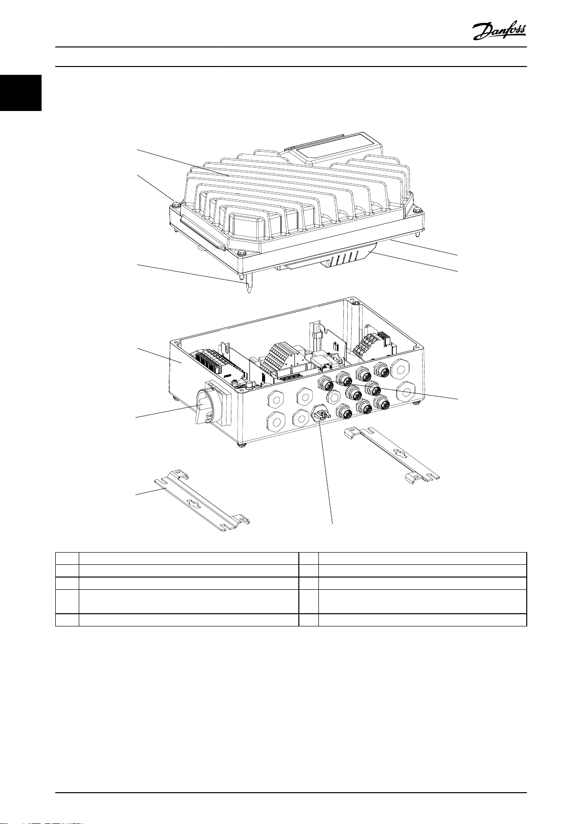
1.4.2 Exploded Views
1 Inverter part 6 Installation box
2 Fastening screws (4 x, 1 in each corner) 7 Display connection
3 Sealing gasket 8 Access to USB port
4 Inverter part plastic cover 9 Service switch-motor side (alternatively, switch located on
mains side, or not mounted)
5 Ground connection pin 10 Flat mounting brackets
Illustration 1.1 Exploded View Small Unit
4 Danfoss A/S © 11/2016 All rights reserved. MG04F502
Page 7
130BC380.10
1
6
5
9
10
2
3
4
7
8
11
Introduction Operating Guide
1 1
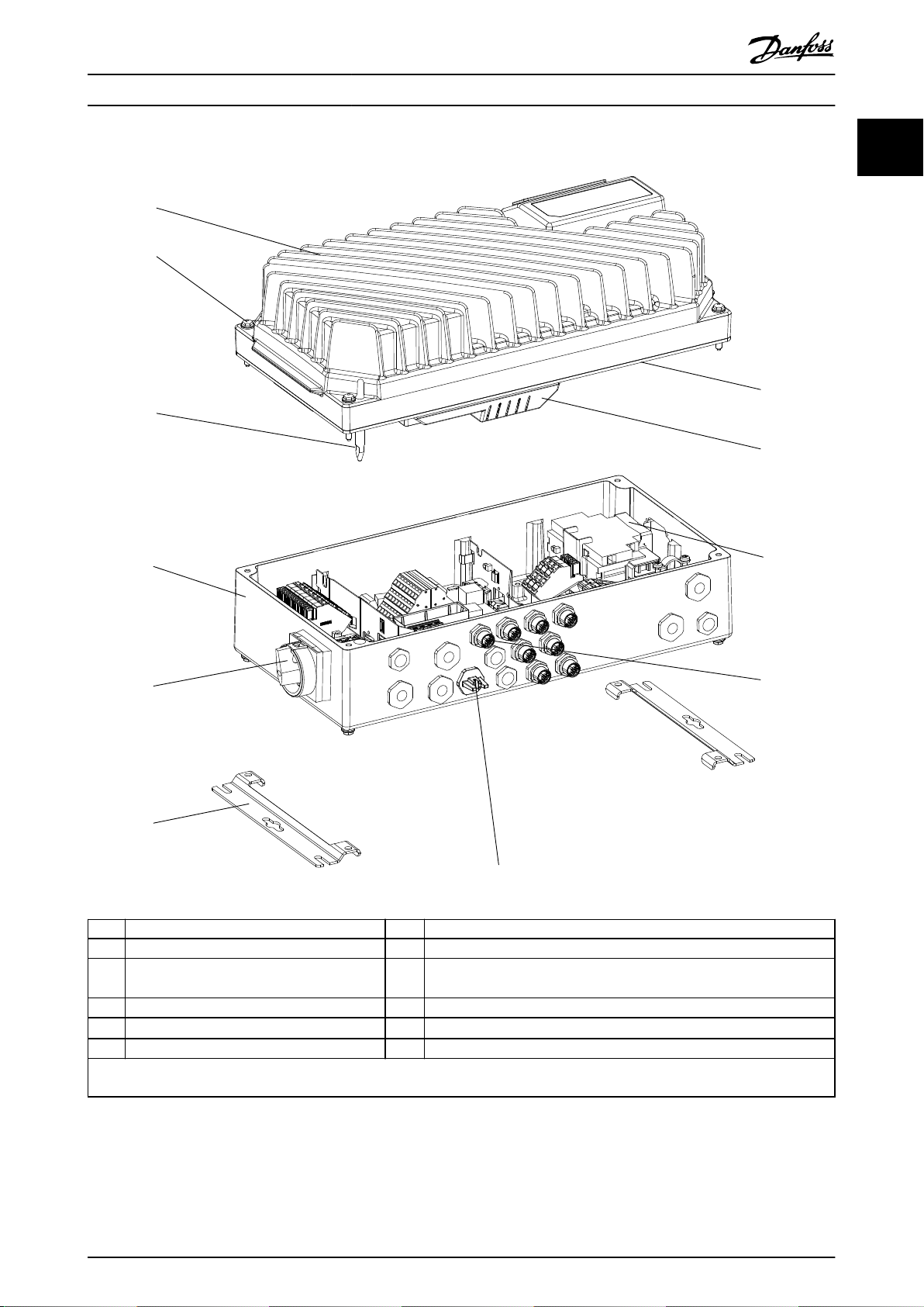
1 Inverter part 7 Display connection
2 Fastening screws (4 x, 1 in each corner) 8 Access to USB port
3 Sealing gasket 9
Service switch1) - motor side (alternatively, switch located on mains side, or
not mounted)
4 Inverter part plastic cover 10 Flat mounting brackets
5 Ground connection pin 11
Circuit breaker1) (optional)
6 Installation box – –
1) The unit can be congured with either service switch or circuit breaker, not both. The illustration shown is not congurable in practice, but is
shown to illustrate the respective positions of components only.
Illustration 1.2 Exploded View Large Unit
MG04F502 Danfoss A/S © 11/2016 All rights reserved. 5
Page 8
Introduction
VLT® Decentral Drive FCD 302
11
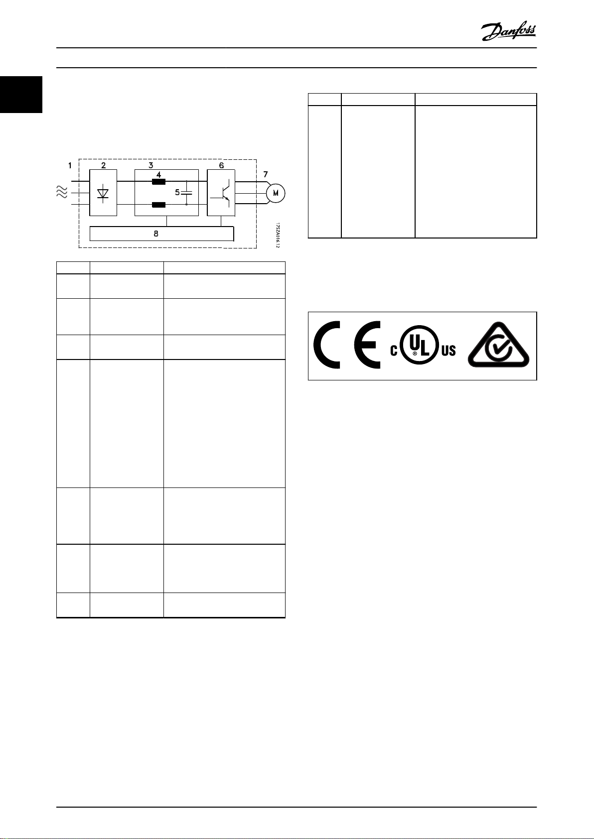
1.4.3 Block Diagram
Illustration 1.3 is a block diagram of the internal
components of the frequency converter.
Area Title Functions
1 Mains input
2 Rectier
3 DC bus
4 DC reactors
5 Capacitor bank
6 Inverter
7 Output to motor
3-phase AC mains supply to the
frequency converter.
The rectier bridge converts the
AC input to DC current to supply
inverter power.
Intermediate DC-bus circuit
handles the DC current.
Filter the intermediate DC
•
circuit voltage.
Provide mains transient
•
protection.
Reduce RMS current.
•
Raise the power factor
•
reected back to the line.
Reduce harmonics on the AC
•
input.
Stores the DC power.
•
Provides ride-through
•
protection for short power
losses.
The inverter converts the DC into
a controlled PWM AC waveform
for a controlled variable output to
the motor.
Regulated 3-phase output power
to the motor.
Area Title Functions
Input power, internal
•
processing, output, and motor
current are monitored to
provide ecient operation
and control.
8 Control circuitry
Illustration 1.3 Frequency Converter Block Diagram
User interface and external
•
commands are monitored and
performed.
Status output and control can
•
be provided.
1.5 Approvals and Certications
Table 1.2 Approvals and Certications
More approvals and certications are available. Contact the
local Danfoss partner. Frequency converters of enclosure
size T7 (525–690 V) are UL certied for only 525–600 V.
The frequency converter complies with UL 508C thermal
memory retention requirements. For more information,
refer to the section Motor Thermal Protection in the
product-specic design guide.
For compliance with the European Agreement concerning
International Carriage of Dangerous Goods by Inland
Waterways (ADN), refer to ADN-compliant Installation in the
product-specic design guide.
6 Danfoss A/S © 11/2016 All rights reserved. MG04F502
Page 9

Introduction Operating Guide
1.6 Symbols and Conventions
The following symbols are used in this manual:
WARNING
Indicates a potentially hazardous situation that could
result in death or serious injury.
CAUTION
Indicates a potentially hazardous situation that could
result in minor or moderate injury. It may also be used
to alert against unsafe practices.
NOTICE
Indicates important information, including situations that
may result in damage to equipment or property.
The following conventions are used in this manual:
Numbered lists indicate procedures.
•
Bullet lists indicate other information and
•
description of illustrations.
Italicized text indicates:
•
- Cross-reference.
- Link.
- Footnote.
- Parameter name.
- Parameter group name.
- Parameter option.
All dimensions in drawings are in mm (inch).
•
1 1
MG04F502 Danfoss A/S © 11/2016 All rights reserved. 7
Page 10
Safety
VLT® Decentral Drive FCD 302
2 Safety
22
2.1 Safety Symbols
The following symbols are used in this guide:
WARNING
Indicates a potentially hazardous situation that could
result in death or serious injury.
CAUTION
Indicates a potentially hazardous situation that could
result in minor or moderate injury. It can also be used to
alert against unsafe practices.
NOTICE
Indicates important information, including situations that
can result in damage to equipment or property.
2.2 Qualied Personnel
WARNING
UNINTENDED START
When the frequency converter is connected to AC mains,
DC supply, or load sharing, the motor may start at any
time. Unintended start during programming, service, or
repair work can result in death, serious injury, or
property damage. The motor can start via an external
switch, a eldbus command, an input reference signal
from the LCP, or after a cleared fault condition.
To prevent unintended motor start:
Disconnect the frequency converter from the
•
mains.
Press [O/Reset] on the LCP before
•
programming parameters.
Completely wire and assemble the frequency
•
converter, motor, and any driven equipment
before connecting the frequency converter to
AC mains, DC supply, or load sharing.
Correct and reliable transport, storage, installation,
operation, and maintenance are required for the troublefree and safe operation of the frequency converter. Only
qualied personnel are allowed to install and operate this
equipment.
Qualied personnel are dened as trained sta, who are
authorized to install, commission, and maintain equipment,
systems, and circuits in accordance with pertinent laws and
regulations. Also, the qualied personnel must be familiar
with the instructions and safety measures described in this
manual.
Safety Precautions
2.3
WARNING
HIGH VOLTAGE
Frequency converters contain high voltage when
connected to AC mains input, DC supply, or load sharing.
Failure to perform installation, start-up, and maintenance
by qualied personnel can result in death or serious
injury.
Only qualied personnel must perform instal-
•
lation, start-up, and maintenance.
WARNING
DISCHARGE TIME
The frequency converter contains DC-link capacitors,
which can remain charged even when the frequency
converter is not powered. High voltage can be present
even when the warning indicator lights are o. Failure to
wait the specied time after power has been removed
before performing service or repair work could result in
death or serious injury.
1. Stop the motor.
2. Disconnect AC mains, permanent magnet type
motors, and remote DC-link supplies, including
battery back-ups, UPS, and DC-link connections
to other frequency converters.
3. Wait for the capacitors to discharge fully before
performing any service or repair work. The
discharge time is specied in Table 2.1.
8 Danfoss A/S © 11/2016 All rights reserved. MG04F502
Page 11
Safety Operating Guide
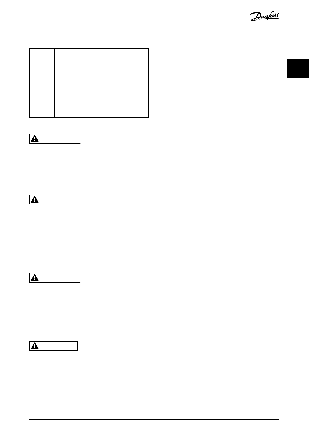
Voltage [V] Minimum waiting time (minutes)
4 7 15
200–240 0.25–3.7 kW
(0.34–5 hp)
380–500 0.25–7.5 kW
(0.34–10 hp)
525–600 0.75–7.5 kW
(1–10 hp)
525–690 – 1.5–7.5 kW
Table 2.1 Discharge Time
– 5.5–37 kW
(7.5–50 hp)
– 11–75 kW
(15–100 hp)
– 11–75 kW
(15–100 hp)
(2–10 hp)
(15–100 hp)
11–75 kW
WARNING
LEAKAGE CURRENT HAZARD
Leakage currents exceed 3.5 mA. Failure to ground the
frequency converter properly can result in death or
serious injury.
Ensure the correct grounding of the equipment
•
by a certied electrical installer.
WARNING
EQUIPMENT HAZARD
Contact with rotating shafts and electrical equipment
can result in death or serious injury.
Ensure that only trained and qualied personnel
•
perform installation, start-up, and maintenance.
Ensure that electrical work conforms to national
•
and local electrical codes.
Follow the procedures in this guide.
•
2 2
WARNING
UNINTENDED MOTOR ROTATION
WINDMILLING
Unintended rotation of permanent magnet motors
creates voltage and can charge the unit, resulting in
death, serious injury, or equipment damage.
Ensure that permanent magnet motors are
•
blocked to prevent unintended rotation.
CAUTION
INTERNAL FAILURE HAZARD
An internal failure in the frequency converter can result
in serious injury when the frequency converter is not
properly closed.
Ensure that all safety covers are in place and
•
securely fastened before applying power.
MG04F502 Danfoss A/S © 11/2016 All rights reserved. 9
Page 12
130BF338.10
VLT®
MADE IN DENMARK
P/N: 131Z5118 S/N: 000000G000
1.5kW(400V) / 2.0HP(460V)
IN: 3x380-480V 50/60Hz, 3.7/3.1A
OUT: 3x0-Vin 0-590Hz, 4.1/3.4A
* 1 3 1
Z
5 1 1 8 0 0 0 0 0 0 G 0 0 0 *
Decentral Drive
www.danfoss.com
T/C: FCD302P1K5T4W66H1X1XMFCFXXXXA0BXXXXXXDX
1
2
4
5
6
7
3
IP66 Enclosure Tamb.
40
˚C/104 ˚F
Enclosure rating:
LISTED E134261 76X1 IND. CONT. EQ.
Type 4X Indoor Use Only
Danfoss A/S
6430 Nordborg
Denmark
8
9
10
Mechanical Installation
3 Mechanical Installation
VLT® Decentral Drive FCD 302
3.1 Unpacking
33
3.1.1 Items Supplied
3.1.2 Product Identication
The packaging contains:
Accessories bag, supplied only with order of
•
installation box. Contents:
- 2 cable clamps
- Bracket for motor cables and loads
cables
- Elevation bracket for cable clamp
- Screw 4 mm x 20 mm
- Thread forming 3.5 mm x 8 mm
Operating Guide
•
Frequency converter
•
Depending on options tted, the box contains 1 or 2 bags
and 1 or more booklets.
Procedure
1. Make sure the items supplied and the information
on the nameplate correspond to the order
conr-
mation.
2. Check the packaging and the frequency converter
visually for damage caused by inappropriate
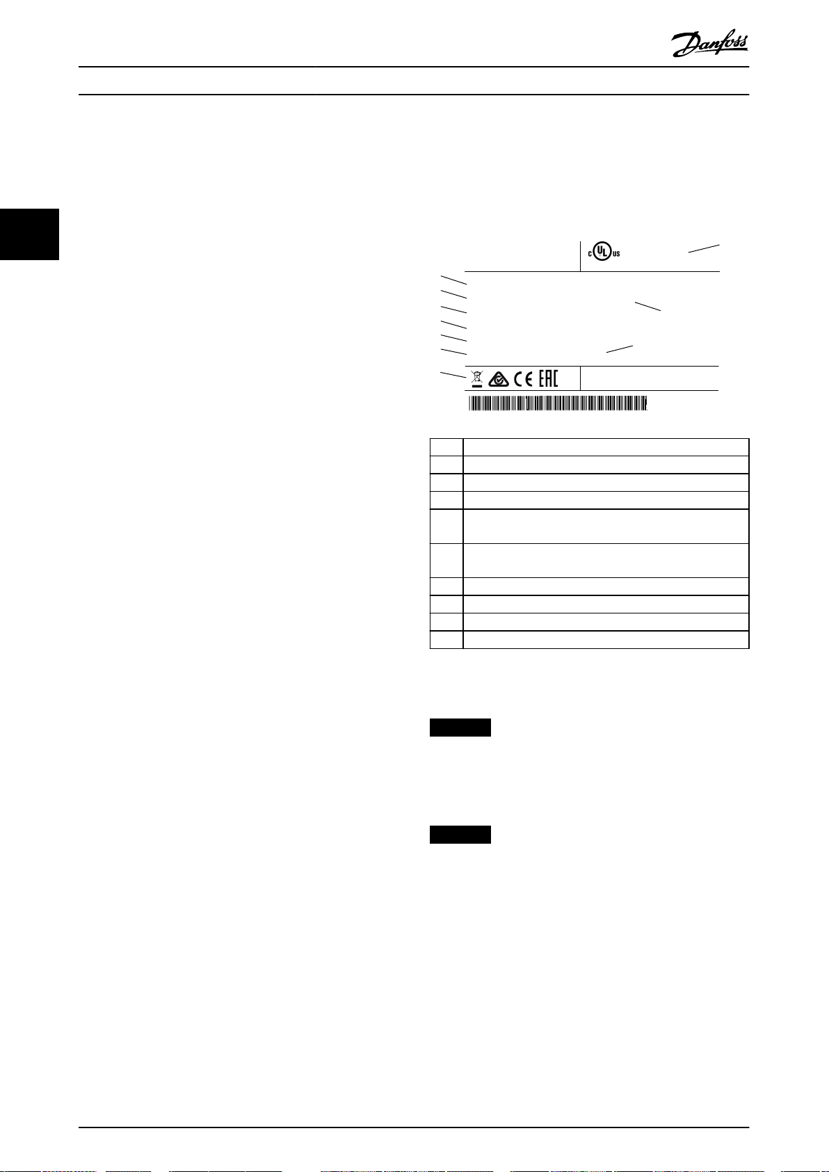
1 Type code
2 Ordering number
3 Serial number
4 Power rating
Input voltage, frequency, and current (at low/high
5
voltages)
Output voltage, frequency, and current (at low/high
6
voltages)
7 IP rating
8 Maximum ambient temperature
9 Certications
10 NEMA enclosure type
handling during shipment. File any claim for
damage with the carrier. Retain damaged parts
Illustration 3.1 Product Nameplate (Example)
for clarication.
10 Danfoss A/S © 11/2016 All rights reserved. MG04F502
NOTICE
Do not remove the nameplate from the frequency
converter (loss of warranty).
3.2 Mounting
NOTICE
In environments with airborne liquids, particles, or
corrosive gases, ensure that the IP/type rating of the
equipment matches the installation environment. Failure
to meet requirements for ambient conditions can reduce
the lifetime of the frequency converter. Ensure that
requirements for air humidity, temperature, and altitude
are met.
Vibration and shock
The frequency converter complies with requirements for
units mounted on the walls and oors of production
premises, and in panels bolted to walls or oors.
For detailed ambient conditions specications, refer to
chapter 7.4 Ambient Conditions.
Page 13
41 mm
(1.61 in)
175 mm (6.88 in)
349.5 mm (13.75 in)
315 mm (12.4 in)
ON
WARNING
ALARM
Bus MS NS2NS1
331.5 mm (13.05 in)
280 mm (11.02 in)
178 mm (7 in)
6.5 mm
(0.25 in)
80 mm
(3.14 in)
190 mm (7.48 in)
25 mm
(0.98 in)
Ø13 mm
(0,51 in)
130BB712.10
200 mm (7.87 in)
1
2
3
4
80 mm
(3.14 in)
130BC381.10
431.5 mm (16.98 in)
380 mm (14.96 in)
178 mm (7 in)
201 mm (7.91 in)
32 mm
(1.25 in)
415 mm (16.33 in)
186 mm (7.32 in)
449.5 mm (17.69 in)
6.5 mm
(0.25 in)
190 mm (7.48 in)
80 mm
(3.14 in)
80 mm
(3.14 in)
Ø13 mm
(0,51 in)
25 mm
(0.98 in)
Mechanical Installation Operating Guide
3.2.1 Recommended Tools and Equipment
Equipment Size Description
Screwdrivers – –
Socket (hex) 8 For fastening inverter
screws/mounting of
brackets
Slotted 0.4x2.5 For spring loaded power
and control terminals
Slotted/torx 1.0x5.5/TX20 For cable clamps inside
the installation box
Spanner 19, 24, 28 For blind-plugs
LCP, ordering
– Local control panel
number 130B1078
LCP cable,
ordering number
– Connection cable for
local control panel
130B5776
Table 3.1 Recommended Tools and Equipment
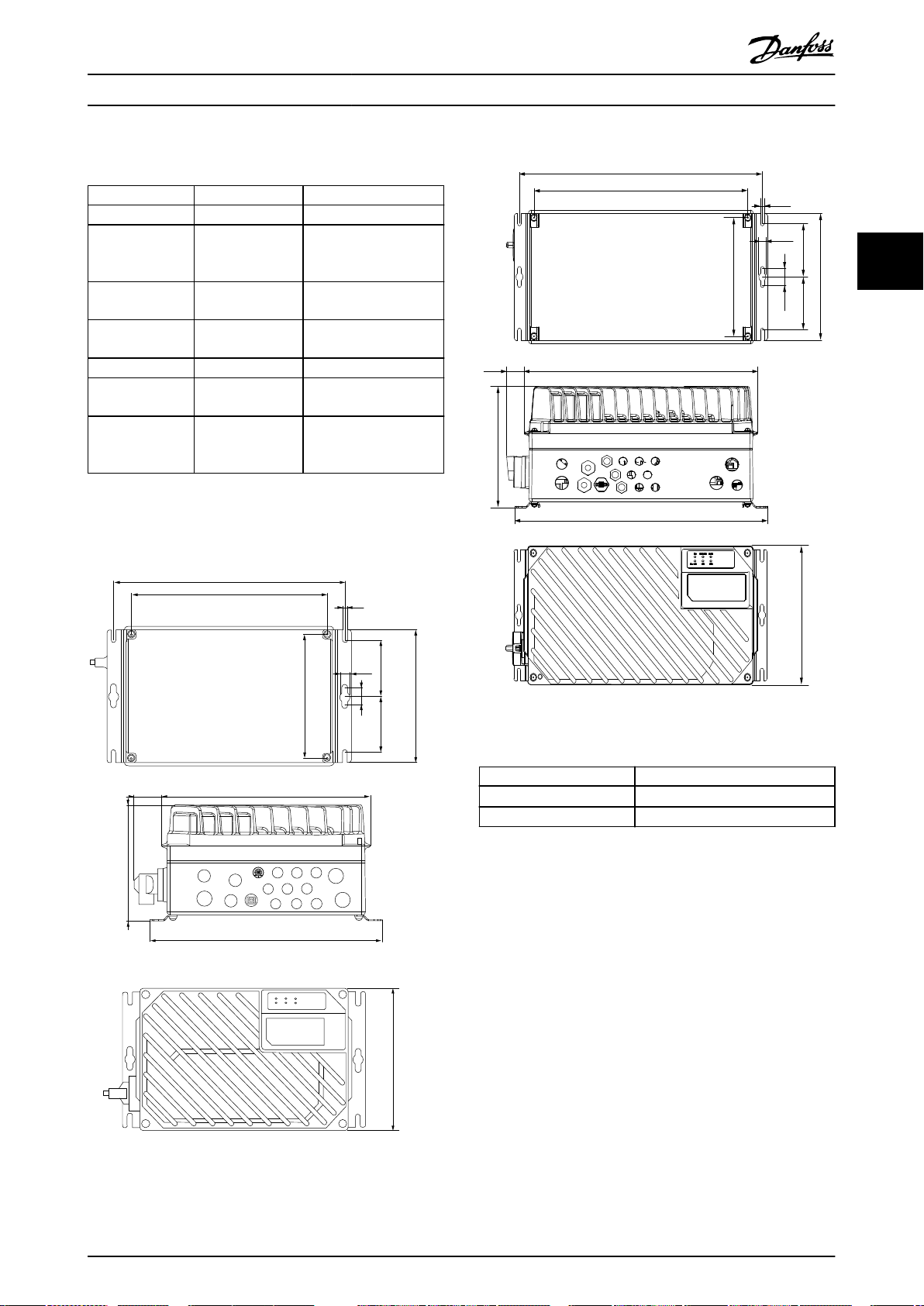
3.2.2 Mechanical Dimensions
3 3
Illustration 3.2 Cable Entries and Hole Sizes (Small Unit)
Illustration 3.3 Cable Entries and Hole Sizes (Large Unit)
Motor side 1xM20, 1xM25
Control side
2xM20, 9xM16
1)
Mains side 2xM25
Table 3.2 Mechanical Dimensions
1) Also used for 4xM12/6xM12 sensor/acuator sockets.
3.2.3 Mounting
The VLT® Decentral Drive FCD 302 consists of 2 parts:
The installation box
•
The inverter part
•
See chapter 1.4.2 Exploded Views.
MG04F502 Danfoss A/S © 11/2016 All rights reserved. 11
Page 14
130BC382.10
130BC383.10
130BB701.10
Mechanical Installation
VLT® Decentral Drive FCD 302
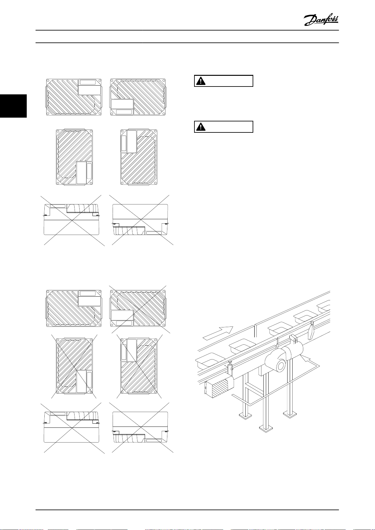
3.2.3.1 Allowed Mounting Positions
3.2.3.2 Mounting the Installation Box
CAUTION
ELECTRICAL HAZARD
Do not apply power to the unit at this stage, as this
33
could result in death or serious injury.
CAUTION
DAMAGE OR PERSONAL INJURY
Failure to tighten the 4 mounting screws can result in
personal injury or material damage.
Ensure that the strength of the mounting
•
location can support the unit weight.
Prerequisites:
Use the holes on the rear of the installation box
•
to x the mounting brackets.
Use proper mounting screws or bolts.
•
For hygienic versions, use cable glands designed
•
to meet hygienic application requirements, for
example Rittal HD 2410.110/120/130.
1.
Illustration 3.4 Allowed Mounting Positions - Standard
Applications
Mount the VLT® Decentral Drive FCD 302
vertically on a wall or machine frame. For
hygienic versions, ensure that liquids drain
enclosure and orient the unit so the cable glands
are located at the base.
o the
Illustration 3.6 FCD 302 Standalone Mounted with Mounting
Brackets
Illustration 3.5 Allowed Mounting Positions - Hygienic
Applications
12 Danfoss A/S © 11/2016 All rights reserved. MG04F502
Page 15
Electrical Installation Operating Guide
4 Electrical Installation
4.1 Safety Instructions
See chapter 2 Safety for general safety instructions.
WARNING
INDUCED VOLTAGE
Induced voltage from output motor cables that run
together can charge equipment capacitors, even with the
equipment turned o and locked out. Failure to run
output motor cables separately or use shielded cables
could result in death or serious injury.
Run output motor cables separately, or
•
Use shielded cables.
•
CAUTION
SHOCK HAZARD
The frequency converter can cause a DC current in the
PE conductor. Failure to follow the recommendation
below means that the RCD may not provide the
intended protection.
When a residual current-operated protective
•
device (RCD) is used for protection against
electrical shock, only an RCD of Type B is
allowed on the supply side.
Overcurrent protection
Additional protective equipment, such as short-
•
circuit protection or motor thermal protection
between frequency converter and motor, is
required for applications with multiple motors.
Input fusing is required to provide short circuit
•
and overcurrent protection. If not factorysupplied, the installer must provide the fuses. See
UL/cUL approved pre-fuses in chapter 7.7 Fuses
and Circuit Breakers.
Wire type and ratings
All wiring must comply with local and national
•
regulations regarding cross-section and ambient
temperature requirements.
Power connection wire recommendation:
•
Minimum 75 °C (167 °F) rated copper wire.
See chapter 7.1 Electrical Data and chapter 7.5 Cable Speci-
cations for recommended wire sizes and types.
EMC-compliant Installation
4.2
To obtain an EMC-compliant installation, follow the
instructions provided in chapter 4.3 Grounding,
chapter 4.4 Wiring Schematic, chapter 4.7 Motor Connection,
and chapter 4.10 Control Wiring.
4.3 Grounding
WARNING
LEAKAGE CURRENT HAZARD
Leakage currents exceed 3.5 mA. Failure to ground the
frequency converter properly could result in death or
serious injury.
Ensure the correct grounding of the equipment
•
by a certied electrical installer.
For electrical safety
Ground the frequency converter in accordance
•
with applicable standards and directives.
Use a dedicated ground wire for input power,
•
motor power, and control wiring.
Do not ground one frequency converter to
•
another in a daisy chain fashion.
Keep the ground wire connections as short as
•
possible.
Follow motor manufacturer wiring requirements.
•
Minimum cable cross-section: 10 mm2 (7 AWG)
•
(or 2 rated ground wires terminated separately).
For EMC-compliant installation
Establish electrical contact between the cable
•
shield and the frequency converter enclosure by
using metal cable glands or by using the clamps
provided on the equipment.
To reduce burst transient, use high-strand wire.
•
Do not use pigtails.
•
4 4
MG04F502 Danfoss A/S © 11/2016 All rights reserved. 13
Page 16

130BC391.10
130BC403.10
Electrical Installation
VLT® Decentral Drive FCD 302
NOTICE
POTENTIAL EQUALISATION
Risk of burst transient, when the ground potential
between the frequency converter and the control system
is dierent. Install equalizing cables between the system
components. Recommended cable cross-section: 16 mm
(5 AWG).
2
44
CAUTION
PE CONNECTION
The metal pins in the corners of the electronic part and
the holes on the corner of the installation box are
essential for the protective earth connection. Make sure
that they are not loosened, removed, or violated in any
way. Tightening torque requirement is 3 Nm. (26 in-lb).
See Illustration 4.1.
Grounding shielded cable
Grounding clamps are provided for motor and control wiring (see Illustration 4.2).
Illustration 4.1 PE Connection between the Installation Box
and the Electronic Part
NOTICE
The external grounding terminal is available as an
accessory (part no: 130B5833).
Illustration 4.2 Grounding for Motor and Control Wiring (Small Unit)
14 Danfoss A/S © 11/2016 All rights reserved. MG04F502
Page 17

130BC390.10
Electrical Installation Operating Guide
4 4
Illustration 4.3 Grounding Clamp for Motor and Control Wiring (Large Unit)
1. To remove the insulation for proper grounding, use a wire stripper.
2. Secure the grounding clamp to the stripped portion of the wire with the screws provided.
3. Secure the grounding wire to the grounding clamp provided.
MG04F502 Danfoss A/S © 11/2016 All rights reserved. 15
Page 18

130BC384.10
3-phase
power
input
Mechanical
brake
+10 V DC
-10 V DC+10 V DC
0/4-20 mA
-10 V DC+10 V DC
0/4-20 mA
91 (L1)
92 (L2)
93 (L3)
95 (PE)
122(MBR+)
123(MBR-)
50 (+10 V OUT)
53 (A IN)
54 (A IN)
55 (COM A IN)
12 (+24 V OUT)
13 (+24 V OUT)
18 (D IN)
19 (D IN)
20 (COM D IN)
27 (D IN/OUT)
29 (D IN/OUT)
24V
OV
32 (D IN)
33 (D IN)
37 (D IN)
S201
S202
ON/I=0-20mA
OFF/U=0-10V
P 5-00
24 V (NPN)
0 V (PNP)
24 V (NPN)
0 V (PNP)
24 V (NPN)
0 V (PNP)
24 V (NPN)
0 V (PNP)
24 V (NPN)
0 V (PNP)
24 V (NPN)
0 V (PNP)
Switch mode
power supply
10 V DC
15 mA
24 V DC
600 mA
(U) 96
(U) 97
(W) 98
(PE) 99
Motor
Brake
resistor
(R+) 82
(R-) 81
Relay1
Relay2
03
02
01
06
05
04
240 V AC, 2A
240 V AC, 2A
400 V AC, 2A
Analog output
0/4–20 mA
(COM A OUT) 39
(A OT) 42
ON=Terminated
OFF=Open
S801
S801
GX
(N RS485) 69
(P RS485) 68
5V
RS485
Interface
(COM RS485) 61
(PNP) = Source
(NPN) = Sink
RS485
ON
1 2
ON
1 2
ON
1 2
0 V
VCXA
PROFIBUS
interface
GND1
GND1
RS485
66
63
62
67
GX
Electrical Installation
VLT® Decentral Drive FCD 302
4.4 Wiring Schematic
44
Illustration 4.4 Basic Wiring Schematic
16 Danfoss A/S © 11/2016 All rights reserved. MG04F502
Page 19

130BC286.10
U
96
V
97
W
98
L1
L2
L3
L1
91
L2
92
L3
93
12
27
T1
T2
T3
NO
NC
NO
NC
L2
L3
PE
L1
41
33
5
3
1 2
4
6
34
42
1
2
L1
L2
L3
PE
U
96
V
97
W
98
L1
91
L2
92
L3
93
12
27
U
V
W
1 2
3 4
5
6
7 8
1
130BC287.10
Electrical Installation Operating Guide
1 Looping terminals
2 Circuit breaker
Illustration 4.5 Large Unit only: Circuit Breaker and Mains
Disconnect
4 4
1 Looping terminals
Illustration 4.6 Large Unit only: Service Switch at Mains with
Looping Terminals
NOTICE
EMC INTERFERENCE
Use shielded cables for motor and control wiring and
separate cables for input power, motor wiring, and
control wiring. Failure to isolate power, motor, and
control cables can result in unintended behavior or
reduced performance. Minimum clearance requirement
between power, motor, and control cables is 200 mm
(7.9 in).
MG04F502 Danfoss A/S © 11/2016 All rights reserved. 17
Page 20

130BC385.10
123
4
5
6
7 8
9
10
11
13
13
13
12
L3/93
L1/91
L2/92
8182123
122
U/96
V/97W/98
R
G
V
N
P
B04
B03
B02 B01
B08
B01 B06
B05
B12
B11 B10 B09
12
18 19 27
29 32 33
12
12
12 12
12
12
13
20
20
20
20 20
20
20
20
20
39
50 54
5355
42
37
37
Electrical Installation
VLT® Decentral Drive FCD 302
4.5 Location of Terminals
44
1 Digital and analog inputs/outputs 8 USB port
2 Safe Torque O (STO), LCP connection, B-option 9 Standard bus/RS485
3 Relay 1 10 PROFIBUS
4 Relay 2 11 Ethernet port
5 Motor, mechanical brake, brake resistor 12 Ethernet port
6 Mains 13 Protective earth (PE)
7 24 V DC back-up input – –
Illustration 4.7 Location of Terminals (Small Unit)
18 Danfoss A/S © 11/2016 All rights reserved. MG04F502
Page 21

130BC386.10
1
2
3
4
5
13
7
8
9
10
13
6
13
11
12
L3/93 L1/91L2/92
8182123122U/96V/97W/98
R
G
V
N
P
B04
B03
B02 B01
B08
B01 B06
B05
B12
B11 B10 B09
12
18 19 27
29 32 33
12
12
12 12
12
12
13
20
20
20
20 20
20
20
20
20
39
50 54
5355
42
37
37
Electrical Installation Operating Guide
4 4
1 Digital and analog inputs/outputs 8 USB port
2 Safe Torque O (STO), LCP connection, B-option 9 Standard bus/RS485
3 Relay 1 10 PROFIBUS
4 Relay 2 11 Ethernet port
5 Motor, mechanical brake, brake resistor 12 Ethernet port
6 Mains 13 Protective Earth (PE)
7 24 V DC back-up input – –
Illustration 4.8 Location of Terminals (Large Unit)
For both small and large units, the service switch is
optional. The switch is shown mounted on the motor side.
Alternatively, the switch can be on the mains side, or
4. Ensure that the contact is rmly established and
not loose. Loose wiring can result in equipment
faults or injury.
omitted.
For the large unit, the circuit breaker is optional. The large
unit can be congured with either service switch or circuit
breaker, not both. The setup shown in Illustration 4.8, is not
congurable in practice, but is shown to illustrate the
respective positions of components only.
4.6 Terminal Types
Motor, control, and mains terminals are spring loaded
(Cage-clamp) type.
1. Open the contact by inserting a small screwdriver
into the slot above the contact, as shown in
Illustration 4.9.
2. Insert the stripped wire into the contact.
3. Remove the screwdriver to fasten the wire into
the contact.
Illustration 4.9 Opening the Terminals
MG04F502 Danfoss A/S © 11/2016 All rights reserved. 19
Page 22

130BB706.10
Electrical Installation
VLT® Decentral Drive FCD 302
4.7 Motor Connection
WARNING
INDUCED VOLTAGE
Induced voltage from output motor cables that run
together can charge equipment capacitors even with the
equipment turned o and locked out. Failure to run
output motor cables separately or to use shielded cables,
44
could result in death or serious injury.
NOTICE
MOTOR OVERLOAD PROTECTION
Protection against motor overload is not included in the
factory setting. If this function is needed, set
parameter 1-90 Motor Thermal Protection to either 1 of
the trip options or 1 of the warning options. Refer to the
VLT® AutomationDrive FC 301/302 Programming Guide for
further information.
1. Connect the motor to terminals 96, 97, 98.
2. Connect ground to the PE-terminal.
3. Make sure that the shield of the motor cable is
properly grounded at both ends (motor and
frequency converter).
4. For correct dimensioning of cable cross-section,
see chapter 7.1 Electrical Data.
4.7.1 Connecting Several Motors
Parallel connection of motors
The frequency converter can control several parallelconnected motors. The total current consumption of the
motors must not exceed the rated output current I
the frequency converter.
M,N
for
NOTICE
Installations with cables connected in a
•
common joint as in Illustration 4.10, is only
recommended for short cable lengths
(maximum 10 m (32.8 ft)).
When motors are connected in parallel,
•
parameter 1-29 Automatic Motor Adaptation
(AMA) cannot be used.
NOTICE
The electronic thermal relay (ETR) of the frequency
converter cannot be used as motor overload protection
for the individual motor in systems with parallelconnected motors. Provide further motor overload
protection by thermistors in each motor or individual
thermal relays. Circuit breakers are not suitable as
protection.
Number
96 97 98 Motor voltage 0–100% of mains voltage.
U V W 3 wires out of motor.
U1 V1 W1
W2 U2 V2
U1 V1 W1 6 wires out of motor, star connected.
PE – – Ground connection.
Table 4.1 Terminals 96, 97, 98
6 wires out of motor.
Connect U2, V2, W2 separately (optional terminal
block).
NOTICE
Do not install power factor correction capacitors
between the frequency converter and the motor.
Do not wire a starting or pole-changing device between
the frequency converter and the motor.
Illustration 4.10 Parallel Connection of Motors
Problems can occur at start-up and at low RPM values,
when motor sizes dier widely. Motors of low rated motor
power have a relatively high ohmic resistance in the stator.
This high-resistance calls for a higher voltage at start and
at low RPM values.
To resolve such a problem:
Reduce the load during start-up on the motor of
•
lowest rated motor power.
Congure parallel connections only between
•
motors of comparable rated motor power.
20 Danfoss A/S © 11/2016 All rights reserved. MG04F502
Page 23

Electrical Installation Operating Guide
4.8 AC Mains Connection
Size wiring based on the input current of the frequency
converter. See the maximum wire size in Table 7.1 in
chapter 7 Specications.
Comply with local and national electrical codes for cable
sizes.
Procedure
1. Connect 3-phase AC input power wiring to
terminals L1, L2, and L3.
2. Depending on the conguration of the
equipment, connect the input power to the
mains terminals or the input disconnect.
3. Ground the cable in accordance with grounding
instructions provided in chapter 4.3 Grounding.
4. When supplied from an isolated mains source (IT
mains or oating delta) or TT/TN-S mains with a
grounded leg (grounded delta), set
parameter 14-50 RFI Filter to OFF. When set to OFF,
the internal RFI lter capacitors between the
chassis and the DC link are isolated to avoid
damage to the DC link and to reduce ground
capacity currents in accordance with IEC 61800-3.
Number
91 92 93 Mains voltage 3x380–480 V
L1 L2 L3 –
PE – – Ground connection
Motor and Mains Connection with
4.9
Service Switch
Illustration 4.11 Motor and Mains Connection with Service
Switch
Control Wiring
4.10
4 4
Table 4.2 Terminal 91, 92, and 93
WARNING
UNINTENDED START
When the frequency converter is connected to AC mains,
DC supply, or load sharing, the motor may start at any
time. Unintended start during programming, service, or
repair work can result in death, serious injury, or
property damage. The motor can start via an external
switch, a eldbus command, an input reference signal
from the LCP, or after a cleared fault condition.
To prevent unintended motor start:
Disconnect the frequency converter from the
•
mains.
Press [O/Reset] on the LCP before
•
programming parameters.
Completely wire and assemble the frequency
•
converter, motor, and any driven equipment
before connecting the frequency converter to
AC mains, DC supply, or load sharing.
MG04F502 Danfoss A/S © 11/2016 All rights reserved. 21
Page 24

Electrical Installation
VLT® Decentral Drive FCD 302
It is recommended that control wiring is rated for
•
600 V.
Isolate control wiring from high-power
•
Terminal
number
62 RxD/TxD –P (red cable) for PROFIBUS. See the
components in the frequency converter.
If the frequency converter is connected to a
•
thermistor, for PELV isolation, ensure that control
wiring is reinforced/double insulated.
44
Terminal
number
01, 02, 03 Relay 1 output. Usable for AC or DC voltage and
04, 05, 06 Relay 2 output. Usable for AC or DC voltage and
12, 13 24 V DC digital supply voltage. Useable for digital
18, 19, 32, 33 Digital inputs. Selectable for NPN or PNP function
27, 29 Digital inputs or outputs. Programmable for either
35 Common (-) for external 24 V control back-up
36 External + 24 V control back-up supply. Optional.
37 Safe Torque O. See chapter 4.16 Safe Torque O
20 Common for digital inputs. To use for digital input
39 Common for analog output.
42 Analog output. Programmable for various
50 10 V DC analog supply voltage. 15 mA maximum
53, 54
55 Common for analog inputs.
61 Common for serial communication (RS485
68 (+), 69 (-) RS485 interface. When the frequency converter is
Function
resistive or inductive loads.
resistive or inductive loads.
inputs and external transducers. To use the 24 V
DC for digital input common, program
parameter 5-00 Digital I/O Mode for PNP operation.
in parameter 5-00 Digital I/O Mode. Default is PNP.
parameter 5-01 Terminal 27 Mode for terminal 27
and parameter 5-02 Terminal 29 Mode for terminal
29 selects input/output function. Default setting is
input.
supply. Optional.
(STO) for details.
common, program parameter 5-00 Digital I/O
Mode for NPN operation.
functions in parameter group 6-5* Analog Output
1. The analog signal is 0–20 mA or 4–20 mA at a
maximum of 500 Ω.
commonly used for a potentiometer or thermistor.
Analog input. Selectable for voltage (0 to ±10 V)
or current (0 or 4 to ±20 mA). Closed is for
current and open is for voltage. Switches are
located on the frequency converter control card.
See chapter 4.14 DIP Switches
interface). See chapter 4.3 Grounding
connected to an RS485 serial communication bus,
a switch on the control card is provided for
termination resistance. Set the switch to ON for
termination and OFF for no termination.
63 RxD/TxD –N (green cable) for PROFIBUS.
66 0 V for PROFIBUS.
67 +5 V for PROFIBUS.
B01–B12 B-option. See dedicated literature for details.
G, R, V, N, P Connection of LCP.
Table 4.3 Terminal Description
4.11 Brake Resistor
Number Function
81 (optional function) R- Brake resistor terminals
82 (optional function) R+
Table 4.4 Brake Resistor Terminals
The connection cable to the brake resistor must be
shielded/armored. Connect the shield to the metal cabinet
of the frequency converter and to the metal cabinet of the
brake resistor with cable clamps.
Dimension the cross-section of the brake cable to match
the brake torque.
4.12
Number Function
122 (optional
function)
123 (optional
function)
Table 4.5 Mechanical Brake Terminals
In hoisting/lowering applications, control of electromechanical brake is required:
•
•
•
•
Function
VLT® PROFIBUS DP MCA 101 Installation Guide for
details.
Mechanical Brake
MBR+ Mechanical brake
UDC = 0.45 x RMS mains voltage
MBR-
The brake is controlled using the special
mechanical brake control/supply terminals 122
and 123.
Select [32] Mechanical brake control in parameter
group 5-4* Relays, [1] Array, Relay 2 for
applications with an electro-mechanical brake.
The brake is released when the motor current
exceeds the preset value in
parameter 2-20 Release Brake Current.
The brake is engaged when the output frequency
is less than the frequency set in
parameter 2-21 Activate Brake Speed [RPM] or
parameter 2-22 Activate Brake Speed [Hz]. The
brake engages only when the frequency
converter performs a stop command.
Maximum current = 0.8 A
When the frequency converter enters alarm mode or is
exposed to an overvoltage situation, the mechanical brake
22 Danfoss A/S © 11/2016 All rights reserved. MG04F502
Page 25

130BC389.10
1
2
3
4
1
2
3
4
1
2
3
4
1
2
3
4
1
2
3
4
1
2
3
4
1
2
3
4
LCP
RL2
RL1
33
USB
3219
FB2 FB1
18
1
2
3
4
1
2
3
4
130BB708.10
1
2
4
3
5
61
68
69
+
130BB489.10
RS485
Electrical Installation Operating Guide
immediately cuts in. For more detailed information, refer to
the VLT® AutomationDrive FC 301/302 Programming Guide.
NOTICE
When the mechanical brake control/supply terminals 122
and 123 are set through parameter group 5-4* Relays, [1]
Array, relay 2, only 1 relay output (relay 1) is available
for free programming.
4.13 Connection of Sensors/Actuators on
M12 Sockets
Pin Wire color Terminal Function
1 Brown 12 +24 V
3 Blue 20 0 V
4 Black 18, 19, 32,33 Digital input
Table 4.6 4xM12 Connection Input
4 4
1 S201 - terminal 53
2 S202 - terminal 54
3 S801 - standard bus termination
4 PROFIBUS termination
5 Fieldbus address
Pin Wire color Terminal Function
1 Brown
Reserved
1)
Reserved
3 Blue 20 0 V
4 Black 02, 05 NO (24 V)
Table 4.7 2xM12 Connection Output
1) When reserved wires for option are used. If not utilized, they can
be cut o.
Illustration 4.12 Connection of Sensors/Actuators on M12
Sockets
Illustration 4.13 Location of DIP Switches
NOTICE
Switches 4 and 5 are only valid for units tted with
eldbus options.
Refer to VLT® PROFIBUS DP MCA 101 Programming Guide for
further information.
RS485 Serial Communication
4.15
Connect RS485 serial communication wiring to terminals
(+)68 and (-)69.
Use shielded serial communication cable
•
(recommended).
See chapter 4.3 Grounding for proper grounding.
•
4.14 DIP Switches
Select analog input terminals 53 and 54 for either
•
voltage (0–10 V) or current (0–20 mA) input
signals.
Set switches S201 (terminal 53) and S202
•
(terminal 54) to select the signal type. ON is for
current, OFF for voltage.
Terminal 53 default is for a speed reference in
•
open loop.
Terminal 54 default is for a feedback signal in
•
closed loop.
MG04F502 Danfoss A/S © 11/2016 All rights reserved. 23
Illustration 4.14 Serial Communication Wiring Diagram
For basic serial communication set-up, select the following:
Page 26

Electrical Installation
VLT® Decentral Drive FCD 302
1. Protocol type in parameter 8-30 Protocol.
2. Frequency converter address in
specications and makes additional protocol-specic
parameters available.
parameter 8-31 Address.
3. Baud rate in parameter 8-32 Baud Rate.
Two communication protocols are internal to the
frequency converter.
Danfoss FC
•
Modbus RTU
44
•
Functions can be programmed remotely using the protocol
software and RS485 connection or in parameter group 8-**
Communications and Options.
Option cards for the frequency converter are available to
provide additional communication protocols. See the
option card documentation for installation and operation
instructions.
4.16 Safe Torque O (STO)
To run STO, additional wiring for the frequency converter is
required. Refer to VLT
Operating Instructions for further information.
®
Frequency Converters Safe Torque O
Selecting a specic communication protocol changes
various default parameter settings to match that protocol’s
4.17 Installation Check List
Before completing installation of the unit, inspect the entire installation as detailed in Table 4.8. Check and mark the items
when completed.
Inspect for Description
Auxiliary
equipment
Cable routing Ensure that input power, motor wiring,
Control wiring•Check for broken or damaged wires
EMC
considerations
Look for auxiliary equipment,
•
switches, disconnects, or input
fuses/circuit breakers located on
input power side of the frequency
converter, or output side to motor.
Examine their operational readiness
and ensure that they are ready in
all respects for operation at full
speed.
Check function and installation of
•
any sensors used for feedback to
the frequency converter.
Remove power factor correction
•
caps on motor(s), if present.
and control wiring are separated or in 3
separate metallic conduits for high
frequency noise isolation.
and connections.
Check the voltage source of the
•
signals, if necessary.
The use of shielded cable or twisted
•
pair is recommended. Ensure that
the shield is terminated correctly at
both ends.
Check for proper installation regarding
electromagnetic compatibility.
☑
Inspect for Description
Environmental
considerations
Cooling
clearance
Fusing and
circuit
breakers
Input and
output power
wiring
Switches Ensure that all switch and disconnect
Grounding The equipment requires a dedicated
Installation
box and
electronics
part
See equipment label for the maximum
ambient operating temperature limits.
Temperature is not to exceed 40 °C
(104 °F). Humidity levels must be 5–
95% non-condensing.
Units require top and bottom clearance
adequate to ensure proper airow for
cooling.
Check that all fuses are inserted rmly
and in operational condition and that
all circuit breakers are in the open
position. Check for proper fusing or
circuit breakers.
Check for loose connections.
•
Check for proper fusing or circuit
•
breakers.
settings are in the proper position.
ground wire from its chassis to the
plant ground. Check for good ground
connections that are tight and free of
oxidation.
Ensure the installation box and the
electronics part is properly closed.
Check that all 4 fastening screws are
tightened with the right torque.
☑
24 Danfoss A/S © 11/2016 All rights reserved. MG04F502
Page 27

Electrical Installation Operating Guide
Inspect for Description
Cable glands
and blind
plugs
Vibration Ensure that the equipment is not
Table 4.8 Start-Up Check List
Ensure that the cable glands and blind
plugs are properly tightened, to
guarantee the right enclosure
protection degree is achieved. Liquids
and/or excessive dust ingress in the
frequency converter can cause
suboptimal performance or damage.
exposed to a high level of vibration.
Mount the panel solidly or use shock
mounts as necessary.
☑
CAUTION
POTENTIAL HAZARD IN THE EVENT OF INTERNAL FAILURE
Risk of personal injury if the frequency converter is not
properly closed.
Before applying power, ensure that all safety
•
covers are in place and securely fastened.
4.18.1 Installing the Inverter Part
4 4
To compress the gasket between the 2 parts:
1. Tighten the 4 connection screws to torque 2.8–
3.0 Nm. (24–26 in-lb).
2. Tighten the 4 screws in diagonally opposite order.
3. Tighten the 2 grounding spears to torque 3.0 Nm.
(26 in-lb).
MG04F502 Danfoss A/S © 11/2016 All rights reserved. 25
Page 28

Commissioning
VLT® Decentral Drive FCD 302
5 Commissioning
6.
5.1 Applying Power
WARNING
UNINTENDED START
When the frequency converter is connected to AC mains,
DC supply, or load sharing, the motor may start at any
time. Unintended start during programming, service, or
55
repair work can result in death, serious injury, or
property damage. The motor can start via an external
switch, a eldbus command, an input reference signal
from the LCP, or after a cleared fault condition.
To prevent unintended motor start:
Disconnect the frequency converter from the
•
mains.
Press [O/Reset] on the LCP before
•
programming parameters.
Completely wire and assemble the frequency
•
converter, motor, and any driven equipment
before connecting the frequency converter to
AC mains, DC supply, or load sharing.
See chapter 2 Safety for general safety instructions.
Apply power to the frequency converter using the
following steps:
WARNING
HIGH VOLTAGE
Frequency converters contain high voltage when
connected to AC mains input power. Failure to perform
installation, start-up, and maintenance by qualied
personnel could result in death or serious injury.
Installation, start-up, and maintenance must be
•
performed by qualied personnel only.
Before applying power:
1. Close the cover properly.
2. Check that all cable glands are rmly tightened.
3. Ensure that input power to the unit is o and
locked out. Do not rely on the frequency
converter disconnect switches for input power
isolation.
4. Verify that there is no voltage on input terminals
L1 (91), L2 (92), and L3 (93), phase-to-phase, and
phase-to-ground.
5. Verify that there is no voltage on output
terminals 96 (U), 97 (V), and 98 (W), phase-tophase, and phase-to-ground.
5.2
The local control panel (LCP) is the combined display and
keypad on the front of the unit.
The LCP has several user functions:
NOTICE
For commissioning via PC, install the MCT 10 Set-up
Software. The software is available for download (basic
version) or for ordering (advanced version, code number
130B1000). For more information and downloads, see
www.danfoss.com/BusinessAreas/DrivesSolutions/Software
+MCT10/MCT10+Downloads.htm.
Conrm continuity of the motor by measuring Ω
values on U–V (96–97), V–W (97–98), and W–U
(98–96).
7. Check for proper grounding of the frequency
converter and the motor.
8. Inspect the frequency converter for loose
connections on the terminals.
9. Conrm that the supply voltage matches the
voltage of the frequency converter and the
motor.
1. Conrm that the input voltage is balanced within
3%. If not, correct the input voltage imbalance
before proceeding. Repeat this procedure after
the voltage correction.
2. Ensure that any optional equipment wiring
matches the installation application.
3. Ensure that all operator devices are in the OFF
position. Panel doors must be closed and covers
securely fastened.
4. Apply power to the unit. Do not start the
frequency converter now. For units with a
disconnect switch, turn it to the ON position to
apply power to the frequency converter.
Local Control Panel Operation
Start, stop, and control speed when in local
•
control.
Show operational data, status, warnings, and
•
cautions.
Program frequency converter functions.
•
Manually reset the frequency converter after a
•
fault when auto reset is inactive.
26 Danfoss A/S © 11/2016 All rights reserved. MG04F502
Page 29

130BD598.10
Auto
on
Reset
Hand
on
Off
Status
Quick
Menu
Main
Menu
Alarm
Log
Back
Cancel
Info
OK
Status
1(1)
36.4 kW
Auto Remote Ramping
0.000
On
Alarm
Warn.
A
7.83 A
799 RPM
B
C
D
53.2 %
1
2
3
4
5
6
7
8
9
10
11
12
13
14
15
16
17
18 19 20 21
Commissioning Operating Guide
NOTICE
During start-up, the LCP shows the message INITIALISING.
When this message is no longer shown, the frequency
converter is ready for operation. Adding or removing
options can extend the duration of start-up.
5.2.1 Graphic Local Control Panel Layout
The graphic local control panel (GLCP) is divided into 4
functional groups (see Illustration 5.1).
A. Display area.
B. Display menu keys.
C. Navigation keys and indicator lights.
D. Operation keys and reset.
Display Parameter Default setting
1 Parameter 0-20 Display
[1617] Speed [RPM]
Line 1.1 Small
2 Parameter 0-21 Display
[1614] Motor Current
Line 1.2 Small
3 Parameter 0-22 Display
[1610] Power [kW]
Line 1.3 Small
4 Parameter 0-23 Display
[1613] Frequency
Line 2 Large
5 Parameter 0-24 Display
[1602] Reference %
Line 3 Large
Table 5.1 Legend to Illustration 5.1, Display Area
B. Display menu keys
Menu keys are used for menu access for parameter set-up,
toggling through status display modes during normal
operation, and viewing fault log data.
Key Function
6 Status Shows operational information.
7 Quick Menu Allows access to programming parameters
for initial set-up instructions and many
detailed application instructions.
8 Main Menu Allows access to all programming
parameters.
9 Alarm Log Shows a list of current warnings, the last
10 alarms, and the maintenance log.
5 5
Table 5.2 Legend to Illustration 5.1, Display Menu Keys
C. Navigation keys and indicator lights (LEDs)
Navigation keys are used for programming functions and
moving the display cursor. The navigation keys also
provide speed control in local operation. There are also 3
frequency converter status indicator lights in this area.
Key Function
Illustration 5.1 GLCP
A. Display area
The display area is activated when the frequency converter
receives power from the mains voltage, a DC bus terminal,
or a 24 V DC external supply.
The information shown on the LCP can be customized for
user applications. Select options in the Quick Menu Q3-13
Display Settings.
MG04F502 Danfoss A/S © 11/2016 All rights reserved. 27
10 Back Reverts to the previous step or list in the
menu structure.
11 Cancel Cancels the last change or command as long
as the display mode is not changed.
12 Info Press for a denition of the function being
showed.
13 Navigation
Keys
Press the navigation keys to move between
items in the menu.
14 OK Press to access parameter groups or to
enable a selection.
Table 5.3 Legend to Illustration 5.1, Navigation Keys
Page 30

130BC394.10
Q1 My Personal Menu
Q2 Quick Setup
Q3 Function Setups
Q5 Changes Made
13.7% 0.75A 1 (1)
Quick Menus
130BC395.10
Q2
0.0 Hz 0.00kW 1(1)
Motor Setup
1 - 21 Motor Power [kW]
2.2 kW
Commissioning
Indicator Color Function
15 On Green The ON indicator light activates
when the frequency converter
receives power from the mains
voltage, a DC bus terminal, or a
24 V external supply.
16 Warn Yellow When warning conditions are met,
the yellow WARN indicator light
comes on and text appears in the
display area identifying the
problem.
17 Alarm Red A fault condition causes the red
55
alarm LED to ash and an alarm
text is shown.
VLT® Decentral Drive FCD 302
Illustration 5.2 Parameter Group Q2 Quick Setup
Table 5.4 Legend to Illustration 5.1, Indicator Lights (LEDs)
D. Operation keys and reset
Operation keys are at the bottom of the LCP.
Key Function
18 [Hand On] Starts the frequency converter in local
control.
An external stop signal by control input
•
or serial communication overrides the
local hand on.
19 O Stops the motor but does not remove power
to the frequency converter.
20 [Auto On] Puts the system in remote operational mode.
Responds to an external start command
•
by control terminals or serial communi-
cation.
21 Reset Resets the frequency converter manually
after a fault has been cleared.
Table 5.5 Legend to Illustration 5.1, Operation Keys and Reset
NOTICE
To adjust the display contrast, press [Status] and the
[▲]/[▼] keys.
3. Select language and press [OK].
4. Then enter the motor data in
parameter 1-20 Motor Power [kW]/
parameter 1-21 Motor Power [HP] through
parameter 1-25 Motor Nominal Speed. The
information can be found on the motor
nameplate. The entire quick menu is shown in
International/North American Default Parameter
Settings
4a Parameter 1-20 Motor Power [kW]
4b Parameter 1-21 Motor Power [HP]
4c Parameter 1-22 Motor Voltage
4d Parameter 1-23 Motor Frequency
4e Parameter 1-24 Motor Current
4f Parameter 1-25 Motor Nominal Speed
5.3 Basic Programming
Frequency converters require basic operational
programming before running for best performance. Basic
operational programming requires entering motor
nameplate data for the motor being operated and the
minimum and maximum motor speeds. Enter the data in
accordance with the following procedure. See
chapter 5.2 Local Control Panel Operation, for detailed
instructions on entering data through the LCP. Enter the
data with power ON, but before operating the frequency
converter.
1. Press [Quick Menu] on the LCP.
2. Use the navigation keys to scroll to parameter
group Q2 Quick Setup and press [OK].
28 Danfoss A/S © 11/2016 All rights reserved. MG04F502
Illustration 5.3 Motor Set-up
5. Continue the set-up of Quick Menu parameters:
5a Parameter 5-12 Terminal 27 Digital Input.
If terminal default is Coast inverse, it is
possible to change this setting to No
function.
5b Parameter 1-29 Automatic Motor
Adaptation (AMA). Set the desired AMA
Page 31

Commissioning Operating Guide
function. Enable complete AMA is
recommended. See details in
chapter 5.4 System Start-up.
5c Parameter 3-02 Minimum Reference. Set
the minimum speed of the motor shaft.
5d Parameter 3-03 Maximum Reference. Set
the maximum speed of the motor shaft.
5e Parameter 3-41 Ramp 1 Ramp Up Time.
Set the ramping up time regarding
synchronous motor speed, ns.
5f Parameter 3-42 Ramp 1 Ramp Down
Time. Set the ramping down time
regarding synchronous motor speed, ns.
5g Parameter 3-13 Reference Site. Set the
site from where the reference must
work.
See chapter 8.1 Quick Menu Parameters for further details.
5.4 System Start-up
Automatic motor adaptation (AMA) is a test procedure
which measures the electrical characteristics of the motor.
The AMA procedure optimizes compatibility between the
frequency converter and the motor. The frequency
converter builds a mathematical model of the motor for
regulating output motor current. The procedure also tests
the input phase balance of electrical power and compares
the motor characteristics with the data entered in
parameters 1–20 to 1–25. Run this procedure at start-up. It
does not cause the motor to run and it does not harm the
motor. For best result, run the procedure on a cold motor.
To run AMA
1. Enter the motor nameplate data in the frequency
converter, as described in chapter 5.3 Basic
Programming.
2. Connect terminal 37 to terminal 13.
3. Connect terminal 27 to terminal 12 or set
parameter 5-12 Terminal 27 Digital Input to [0] No
function.
4. Activate parameter 1-29 Automatic Motor
Adaptation (AMA).
5. Select either complete or reduced AMA.
6. Press [OK]. The display shows Press [Hand On] to
start.
7. Press [Hand On]. A progress bar indicates that the
AMA is in progress.
Stop the AMA during operation
Press [O] - the frequency converter enters alarm mode,
and the display shows that the AMA procedure is
terminated.
Successful AMA
1. The display shows Press [OK] to nish AMA.
2. Press [OK] to exit the AMA state.
Unsuccessful AMA
1. The frequency converter enters alarm mode. A
description of the alarm can be found in
chapter 6.6 List of Warnings and Alarms.
2. Report Value in the [Alarm Log] shows the last
measuring sequence carried out by the AMA,
before the frequency converter entered alarm
mode. This number along with the description of
the alarm helps with troubleshooting. If
contacting Danfoss for service, make sure to
mention number and alarm description.
NOTICE
Frequent causes of unsuccessful AMA:
Incorrectly registered motor nameplate data.
•
Too great a dierence between the motor
•
power size and the frequency converter power
size.
5.4.1 Local Control Test
1. Press [Hand On] to provide a local start command
to the frequency converter.
2. Accelerate the frequency converter by pressing
[▲] to full speed. Moving the cursor left of the
decimal point provides quicker input changes.
3. Note any acceleration problems.
4. Press [O]. Note any deceleration problems.
If acceleration or deceleration problems occur see
chapter 6 Maintenance, Diagnostics, and Troubleshooting.
See chapter 6.6 List of Warnings and Alarms for resetting the
frequency converter after a trip.
5.4.2 System Start-up
The procedure in this section requires wiring and
application programming to be completed. The following
procedure is recommended after application set-up is
completed.
1. Press [Auto On].
2. Apply an external run command.
3. Adjust the speed reference throughout the speed
range.
4. Remove the external run command.
5. Check the sound and vibration levels of the
motor to ensure that the system is working as
intended.
5 5
MG04F502 Danfoss A/S © 11/2016 All rights reserved. 29
Page 32

Commissioning
VLT® Decentral Drive FCD 302
If warnings or alarms occur, see chapter 6.5 Warning and
Alarm Types or chapter 6.6 List of Warnings and Alarms.
5.5 Operation
5.5.1 Uploading/Downloading Data to/from
the LCP
1. Press [O] to stop the motor before uploading or
downloading data.
2. Press [Main Menu], select parameter 0-50 LCP Copy
and press [OK].
55
3. Select [1] All to LCP to upload data to the LCP or
select [2] All from LCP to download data from the
LCP.
4. Press [OK]. A progress bar shows the uploading or
downloading progress.
5. Press [Hand On] or [Auto On] to return to normal
operation.
5.5.2 Changing Parameter Settings
Access and change parameter settings from the Quick
Menu or from the Main Menu. The Quick Menu only gives
access to a limited number of parameters.
1. Press [Quick Menu] or [Main Menu] on the LCP.
2.
Press [▲] [▼] to browse through the parameter
groups, press [OK] to select a parameter group.
3.
Press [▲] [▼] to browse through the parameters,
press [OK] to select a parameter.
4.
Press [▲] [▼] to change the value of a parameter
setting.
5.
Press [◄] [►] to shift digit when a decimal
parameter is in the editing state.
6. Press [OK] to accept the change.
7. Press either [Back] twice to enter Status, or press
[Main Menu] once to enter the Main Menu.
View changes
Quick Menu Q5 - Changes Made lists all parameters
changed from default settings.
The list only shows parameters, which are
•
changed in the current edit set-up.
Parameters, which were reset to default values,
•
are not listed.
The message Empty indicates that no parameters
•
are changed.
5.5.3 Restoring Default Settings
NOTICE
Risk of losing programming, motor data, localization, and
monitoring records by restoration of default settings. To
provide a back-up, upload data to the LCP before initialization.
Restoring the default parameter settings is done by initialization of the frequency converter. Initialization is carried
out through parameter 14-22 Operation Mode
(recommended) or manually.
Initialization using parameter 14-22 Operation
•
Mode does not reset the frequency converter
settings such as hours run, serial communication
selections, personal menu settings, fault log,
alarm log, and other monitoring functions.
Manual initialization erases all motor,
•
programming, localization, and monitoring data
and restores factory default settings.
Recommended initialization procedure via
parameter 14-22 Operation Mode
1. Press [Main Menu] twice to access parameters.
2. Scroll to parameter 14-22 Operation Mode and
press [OK].
3. Scroll to [2] initialization and press [OK].
4. Remove power to the unit and wait for the
display to turn o.
5. Apply power to the unit.
Default parameter settings are restored during start-up.
The start-up may take slightly longer than normal.
6. Alarm 80, Drive initialized to default value is shown.
7. Press [Reset] to return to operating mode.
Manual initialization procedure
1. Remove power to the unit and wait for the
display to turn o.
2. Press and hold [Status], [Main Menu], and [OK] at
the same time while applying power to the unit
(approximately 5 s or until audible click and fan
starts).
Factory default parameter settings are restored during
start-up. The start-up may take slightly longer than usual.
Manual initialization does not reset the following
frequency converter information:
Parameter 15-00 Operating hours.
•
Parameter 15-03 Power Up's.
•
Parameter 15-04 Over Temp's.
•
Parameter 15-05 Over Volt's.
•
30 Danfoss A/S © 11/2016 All rights reserved. MG04F502
Page 33

130BB710.10
AlarmON
Bus MS NS1 NS2
Warning
Maintenance, Diagnostics, a... Operating Guide
6 Maintenance, Diagnostics, and Troubleshooting
6.1 Introduction
This chapter includes:
Maintenance and service guidelines.
•
Status messages.
•
Warnings and alarms.
•
Basic troubleshooting.
•
Do not dispose of equipment containing
electrical components together with
domestic waste.
Collect it separately in accordance with
local and currently valid legislation.
6.2 Maintenance and Service
Under normal operating conditions and load proles, the
frequency converter is maintenance-free throughout its
designed lifetime. To prevent breakdown, danger, and
damage, examine the frequency converter at regular
intervals depending on the operating conditions. Replace
worn or damaged parts with original spare parts or
standard parts. For service and support, contact the local
Danfoss supplier.
WARNING
UNINTENDED START
When the frequency converter is connected to AC mains,
DC supply, or load sharing, the motor can start at any
time. Unintended start during programming, service, or
repair work can result in death, serious injury, or
property damage. The motor can start with an external
switch, a eldbus command, an input reference signal
from the LCP or LOP, via remote operation using MCT 10
Set-up Software, or after a cleared fault condition.
To prevent unintended motor start:
Press [O/Reset] on the LCP before
•
programming parameters.
Disconnect the frequency converter from the
•
mains.
Completely wire and assemble the frequency
•
converter, motor, and any driven equipment
before connecting the frequency converter to
AC mains, DC supply, or load sharing.
6.2.1 Cleaning
The enclosure (IP66/NEMA type 4x indoor) provides
protection against dirt and water ingress. The enclosure is
suitable for cleaning methods and solvents used in food
and beverage plants. Use the solvent concentration
recommended by the manufacturer. Avoid high-pressure
hot water cleaning at close proximity or of long duration,
because this method of cleaning can damage gaskets and
labels.
6.3 Frontal LEDs
The actual status can be read via 6 LEDs, which signal the
actual status of the unit. The meaning of each LED is
described in Table 6.1.
Illustration 6.1 Frontal LEDs
Name Color Status Indication
ON Green On The frequency converter
receives power from mains
voltage, or 24 V external
supply.
O No power from mains
voltage, or 24 V external
supply.
Warning Yellow On Warning situation is present.
O No warning is present.
Alarm Red Flashing Alarm is present.
O No alarm is present
Bus MS Only relevant if
Bus NS1 Bus network status 1
Bus NS2 Bus network status 2
Table 6.1 LED Status
optional eldbus is
present. See the VLT
AutomationDrive FC
302 PROFIBUS
Converter Operating
Instructions, VLT
Ethernet/IP MCA 121
Installation Guide, and
VLT® PROFINET MCA
120 Installation Guide
for specic
information.
Bus module status
®
®
6
6
MG04F502 Danfoss A/S © 11/2016 All rights reserved. 31
Page 34

Status
799RPM 7.83A 36.4kW
0.000
53.2%
1(1)
Auto
Hand
O
Remote
Local
Ramping
Stop
Running
Jogging
.
.
.
Stand by
130BB037.11
1 2 3
Maintenance, Diagnostics, a...
VLT® Decentral Drive FCD 302
6
6.4 Status Messages
When the frequency converter is in Status mode, status
messages are generated automatically and appear in the
bottom line of the display (see Illustration 6.2).
1 Operating mode (see Table 6.2)
2 Reference site (see Table 6.3)
3 Operation status (see Table 6.4)
Illustration 6.2 Status Display
Table 6.2 to Table 6.4 describe the status messages shown.
O The frequency converter does not react to any
control signal until [Auto On] or [Hand On] is
pressed.
Auto On The frequency converter is controlled from the
control terminals and/or the serial communi-
cation.
Hand On Control the frequency converter via the
navigation keys on the LCP. Stop commands,
reset, reversing, DC brake, and other signals
applied to the control terminals override local
control.
Table 6.2 Operating Mode
Remote The speed reference is given from external
signals, serial communication, or internal
preset references.
Local The frequency converter uses [Hand On]
control or reference values from the LCP.
Table 6.3 Reference Site
32 Danfoss A/S © 11/2016 All rights reserved. MG04F502
AC Brake [2] AC brake is selected in parameter 2-10 Brake
Function. The AC brake overmagnetizes the
motor to achieve a controlled slow down.
AMA nish OK AMA was carried out successfully.
AMA ready AMA is ready to start. Press [Hand On] to start.
AMA running AMA process is in progress.
Braking The brake chopper is in operation. Generative
energy is absorbed by the brake resistor.
Braking max. The brake chopper is in operation. The power
limit for the brake resistor dened in
parameter 2-12 Brake Power Limit (kW) has
been reached.
Coast
Ctrl. ramp-down [1] Control Ramp-down was selected in
Current High The frequency converter output current is
Current Low The frequency converter output current is
DC Hold [1] DC hold is selected in
DC Stop The motor is held with a DC current
Feedback high The sum of all active feedbacks is above the
Feedback low The sum of all active feedbacks is below the
[2] Coast inverse was selected as a function
•
for a digital input (parameter group 5-1*
Digital Inputs). The corresponding terminal
is not connected.
Coast activated by serial communication.
•
parameter 14-10 Mains Failure.
The mains voltage is below the value set
•
in parameter 14-11 Mains Voltage at Mains
Fault at mains fault.
The frequency converter ramps down the
•
motor using a controlled ramp down.
above the limit set in parameter 4-51 Warning
Current High.
below the limit set in parameter 4-52 Warning
Speed Low.
parameter 1-80 Function at Stop, and a stop
command is active. The motor is held by a DC
current set in parameter 2-00 DC Hold/Preheat
Current.
(parameter 2-01 DC Brake Current) for a
specied time (parameter 2-02 DC Braking
Time).
The DC brake cut-in speed is reached in
•
parameter 2-03 DC Brake Cut In Speed
[RPM], and a stop command is active.
[5] DC-brake inverse is selected as a
•
function for a digital input (parameter
group 5-1* Digital Inputs). The
corresponding terminal is not active.
The DC brake is activated via serial
•
communication.
feedback limit set in parameter 4-57 Warning
Feedback High.
feedback limit set in parameter 4-56 Warning
Feedback Low.
Page 35

Maintenance, Diagnostics, a... Operating Guide
Freeze output The remote reference is active, which holds
the present speed.
[20] Freeze output is selected as a function
•
for a digital input (parameter group 5-1*
Digital Inputs). The corresponding terminal
is active. Speed control is only possible via
the terminal options [21] Speed up and [22]
Speed down.
Hold ramp is activated via serial communi-
•
cation.
Freeze output
request
Freeze ref. [19] Freeze reference is selected as a function
Jog request A jog command was given, but the motor
Jogging The motor is running as programmed in
Motor check In parameter 1-80 Function at Stop, [2] Motor
OVC control Overvoltage control is activated via
PowerUnit O (Only frequency converters with a 24 V
A freeze output command was given, but the
motor remains stopped until a run permissive
signal is received.
for a digital input (parameter group 5-1* Digital
Inputs). The corresponding terminal is active.
The frequency converter saves the actual
reference. Changing the reference is now only
possible via terminal options [21] Speed up
and [22] Speed down.
remains stopped until a run permissive signal
is received via a digital input.
parameter 3-19 Jog Speed [RPM].
[14] Jog was selected as a function for a
•
digital input (parameter group 5-1* Digital
Inputs). The corresponding terminal (for
example, terminal 29) is active.
The jog function is activated via the serial
•
communication.
The jog function is selected as a reaction
•
for a monitoring function (for example, for
the no signal function). The monitoring
function is active.
Check is selected. A stop command is active.
To ensure that a motor is connected to the
frequency converter, a permanent test current
is applied to the motor.
parameter 2-17 Over-voltage Control, [2]
Enabled. The connected motor supplies the
frequency converter with generative energy.
The overvoltage control adjusts the V/Hz ratio
to run the motor in controlled mode and to
prevent the frequency converter from tripping.
external supply installed).
Mains supply to the frequency converter was
removed, and the control card is supplied by
the external 24 V.
Protection md Protection mode is active. The unit detected a
critical status (overcurrent or overvoltage).
To avoid tripping, the switching frequency
•
is reduced to 4 kHz.
If possible, protection mode ends after
•
approximately 10 s.
Protection mode can be restricted in
•
parameter 14-26 Trip Delay at Inverter Fault.
Qstop The motor is decelerating using
parameter 3-81 Quick Stop Ramp Time.
[4] Quick stop inverse is selected as a
•
function for a digital input (parameter
group 5-1* Digital Inputs). The
corresponding terminal is not active.
The quick stop function is activated via
•
serial communication.
Ramping The motor accelerates/decelerates using the
active ramp up/down. The reference, a limit
value, or a standstill is not yet reached.
Ref. high The sum of all active references is above the
reference limit set in parameter 4-55 Warning
Reference High.
Ref. low The sum of all active references is below the
reference limit set in parameter 4-54 Warning
Reference Low.
Run on ref. The frequency converter runs in the reference
range. The feedback value matches the
setpoint value.
Run request A start command was given, but the motor
remains stopped until a run permissive signal
is received via digital input.
Running The frequency converter drives the motor.
Sleep Mode The energy-saving function is enabled. The
motor has stopped, but restarts automatically
when required.
Speed high Motor speed is above the value set in
parameter 4-53 Warning Speed High.
Speed low Motor speed is below the value set in
parameter 4-52 Warning Speed Low.
Standby In auto-on mode, the frequency converter
starts the motor with a start signal from a
digital input or serial communication.
Start delay In parameter 1-71 Star t Delay, a delay starting
time was set. A start command is activated,
and the motor starts after the start delay time
expires.
Start fwd/rev [12] Enable start forward and [13] Enable start
reverse are selected as options for 2 dierent
digital inputs (parameter group 5-1* Digital
Inputs). The motor starts in forward or reverse
direction depending on which terminal is
activated.
6
6
MG04F502 Danfoss A/S © 11/2016 All rights reserved. 33
Page 36

130BP086.11
Status
0.0Hz 0.000kW 0.00A
0.0Hz
0
Earth Fault [A14]
Auto Remote Trip
1(1)
Back
Cancel
Info
OK
On
Alarm
Warn.
130BB467.11
Maintenance, Diagnostics, a...
VLT® Decentral Drive FCD 302
6
Stop The frequency converter received a stop
command from the LCP, digital input, or serial
communication.
Trip An alarm occurred and the motor is stopped.
Once the cause of the alarm is cleared, the
frequency converter can be reset manually by
pressing [Reset] or remotely by control
terminals or serial communication.
Trip lock An alarm occurred, and the motor is stopped.
When the cause of the alarm is cleared, cycle
power to the frequency converter. The
frequency converter can then be reset
manually by pressing [Reset], or remotely by
control terminals or serial communication.
Table 6.4 Operation Status
NOTICE
In auto/remote mode, the frequency converter requires
external commands to execute functions.
6.5 Warning and Alarm Types
Warnings
A warning is issued when an alarm condition is impending,
or when an abnormal operating condition is present and
may result in the frequency converter issuing an alarm. A
warning clears by itself when the abnormal condition
ceases.
Alarms
An alarm indicates a fault that requires immediate
attention. The fault always triggers a trip or a trip lock.
Reset the system after an alarm.
Trip
An alarm is issued when the frequency converter is
tripped, meaning that the frequency converter suspends
operation to prevent frequency converter or system
damage. The motor coasts to a stop. The frequency
converter logic continues to operate and monitor the
frequency converter status. After the fault condition is
remedied, the frequency converter can be reset. It is then
ready to start operation again.
Resetting the frequency converter after trip/trip lock
A trip can be reset in any of 4 ways:
Press [Reset] on the LCP.
•
Digital reset input command.
•
Serial communication reset input command.
•
Auto reset.
•
Trip lock
Input power is cycled. The motor coasts to a stop. The
frequency converter continues to monitor the frequency
converter status. Remove input power to the frequency
converter, correct the cause of the fault, and reset the
frequency converter.
Warning and alarm displays
A warning is shown in the LCP along with the
•
warning number.
An alarm ashes along with the alarm number.
•
Illustration 6.3 Alarm Example
In addition to the text and alarm code in the LCP, there are
3 status indicator lights.
Warning indicator light Alarm indicator light
Warning On O
Alarm O On (ashing)
Trip lock On On (ashing)
Illustration 6.4 Status Indicator Lights
6.6 List of Warnings and Alarms
The following warning and alarm information denes each
warning or alarm condition, provides the probable cause
for the condition, and details a remedy or troubleshooting
procedure.
WARNING 1, 10 Volts low
The control card voltage is less than 10 V from terminal 50.
Remove some of the load from terminal 50, as the 10 V
supply is overloaded. Maximum 15 mA or minimum 590 Ω.
A short circuit in a connected potentiometer or incorrect
wiring of the potentiometer can cause this condition.
Troubleshooting
Remove the wiring from terminal 50. If the
•
warning clears, the problem is with the wiring. If
the warning does not clear, replace the control
card.
34 Danfoss A/S © 11/2016 All rights reserved. MG04F502
Page 37

Maintenance, Diagnostics, a... Operating Guide
WARNING/ALARM 2, Live zero error
This warning or alarm only appears if programmed in
parameter 6-01 Live Zero Timeout Function. The signal on 1
of the analog inputs is less than 50% of the minimum
value programmed for that input. Broken wiring or a faulty
device sending the signal can cause this condition.
Troubleshooting
Check connections on all analog mains terminals.
•
- Control card terminals 53 and 54 for
signals, terminal 55 common.
-
VLT® General Purpose I/O MCB 101
terminals 11 and 12 for signals, terminal
10 common.
-
VLT® Analog I/O Option MCB 109
terminals 1, 3, and 5 for signals,
terminals 2, 4, and 6 common.
Check that the frequency converter programming
•
and switch settings match the analog signal type.
Perform an input terminal signal test.
•
WARNING/ALARM 3, No motor
No motor is connected to the output of the frequency
converter.
WARNING/ALARM 4, Mains phase loss
A phase is missing on the supply side, or the mains
voltage imbalance is too high. This message also appears
for a fault in the input
parameter 14-12 Function at Mains Imbalance.
Troubleshooting
Check the supply voltage and supply currents to
•
the frequency converter.
WARNING 5, DC link voltage high
The DC-link voltage (DC) is higher than the high-voltage
warning limit. The limit depends on the frequency
converter voltage rating. The unit is still active.
WARNING 6, DC link voltage low
The DC-link voltage (DC) is lower than the low voltage
warning limit. The limit depends on the frequency
converter voltage rating. The unit is still active.
WARNING/ALARM 7, DC overvoltage
If the DC-link voltage exceeds the limit, the frequency
converter trips after a certain time.
Troubleshooting
Connect a brake resistor.
•
Extend the ramp time.
•
Change the ramp type.
•
Activate the functions in parameter 2-10 Brake
•
Function.
Increase parameter 14-26 Trip Delay at Inverter
•
Fault.
rectier. Options are programmed in
If the alarm/warning occurs during a power sag,
•
use kinetic back-up (parameter 14-10 Mains
Failure).
WARNING/ALARM 8, DC under voltage
If the DC-link voltage drops below the undervoltage limit,
the frequency converter checks for 24 V DC back-up
supply. If no 24 V DC back-up supply is connected, the
frequency converter trips after a xed time delay. The time
delay varies with unit size.
Troubleshooting
Check that the supply voltage matches the
•
frequency converter voltage.
Perform an input voltage test.
•
Perform a soft-charge circuit test.
•
WARNING/ALARM 9, Inverter overload
The frequency converter has run with more than 100%
overload for too long and is about to cut out. The counter
for electronic thermal inverter protection issues a warning
at 98% and trips at 100% with an alarm. The frequency
converter cannot be reset until the counter is below 90%.
Troubleshooting
Compare the output current shown on the LCP
•
with the frequency converter rated current.
Compare the output current shown on the LCP
•
with the measured motor current.
Show the thermal frequency converter load on
•
the LCP and monitor the value. When running
above the frequency converter continuous
current rating, the counter increases. When
running below the frequency converter
continuous current rating, the counter decreases.
WARNING/ALARM 10, Motor overload temperature
According to the electronic thermal protection (ETR), the
motor is too hot.
Select 1 of these options:
The frequency converter issues a warning or an
•
alarm when the counter is >90% if
parameter 1-90 Motor Thermal Protection is set to
warning options.
The frequency converter trips when the counter
•
reaches 100% if parameter 1-90 Motor Thermal
Protection is set to trip options.
The fault occurs when the motor runs with more than
100% overload for too long.
Troubleshooting
Check for motor overheating.
•
Check if the motor is mechanically overloaded.
•
Check that the motor current set in
•
parameter 1-24 Motor Current is correct.
Ensure that the motor data in parameters 1-20 to
•
1-25 are set correctly.
6
6
MG04F502 Danfoss A/S © 11/2016 All rights reserved. 35
Page 38

Maintenance, Diagnostics, a...
VLT® Decentral Drive FCD 302
6
If an external fan is in use, check that it is
•
selected in parameter 1-91 Motor External Fan.
Running AMA in parameter 1-29 Automatic Motor
•
Adaptation (AMA) tunes the frequency converter
to the motor more accurately and reduces
thermal loading.
WARNING/ALARM 11, Motor thermistor overtemp
Check whether the thermistor is disconnected. Select
whether the frequency converter issues a warning or an
alarm in parameter 1-90 Motor Thermal Protection.
Troubleshooting
Check for motor overheating.
•
Check if the motor is mechanically overloaded.
•
When using terminal 53 or 54, check that the
•
thermistor is connected correctly between either
terminal 53 or 54 (analog voltage input) and
terminal 50 (+10 V supply). Also check that the
terminal switch for 53 or 54 is set for voltage.
Check that parameter 1-93 Thermistor Resource
selects terminal 53 or 54.
When using terminal 18, 19, 31, 32, or 33 (digital
•
inputs), check that the thermistor is connected
correctly between the digital input terminal used
(digital input PNP only) and terminal 50. Select
the terminal to use in parameter 1-93 Thermistor
Resource.
WARNING/ALARM 12, Torque limit
The torque has exceeded the value in
parameter 4-16 Torque Limit Motor Mode or the value in
parameter 4-17 Torque Limit Generator Mode.
Parameter 14-25 Trip Delay at Torque Limit can change this
warning from a warning-only condition to a warning
followed by an alarm.
Troubleshooting
If the motor torque limit is exceeded during
•
ramp-up, extend the ramp-up time.
If the generator torque limit is exceeded during
•
ramp-down, extend the ramp-down time.
If torque limit occurs while running, increase the
•
torque limit. Make sure that the system can
operate safely at a higher torque.
Check the application for excessive current draw
•
on the motor.
WARNING/ALARM 13, Over current
The inverter peak current limit (approximately 200% of the
rated current) is exceeded. The warning lasts approximately
1.5 s, then the frequency converter trips and issues an
alarm. Shock loading or quick acceleration with high-inertia
loads can cause this fault. If the acceleration during rampup is quick, the fault can also appear after kinetic back-up.
If extended mechanical brake control is selected, a trip can
be reset externally.
Troubleshooting
Remove the power and check if the motor shaft
•
can be turned.
Check that the motor size matches the frequency
•
converter.
Check that the motor data is correct in
•
parameters 1-20 to 1-25.
ALARM 14, Earth (ground) fault
There is current from the output phase to ground, either in
the cable between the frequency converter and the motor,
or in the motor itself. The current transducers detect the
ground fault by measuring current going out from the
frequency converter and current going into the frequency
converter from the motor. Ground fault is issued if the
deviation of the 2 currents is too large. The current going
out of the frequency converter must be the same as the
current going into the frequency converter.
Troubleshooting
Remove power to the frequency converter and
•
repair the ground fault.
Check for ground faults in the motor by
•
measuring the resistance to ground of the motor
cables and the motor with a megohmmeter.
Reset any potential individual oset in the 3
•
current transducers in the frequency converter.
Perform the manual initialization or perform a
complete AMA. This method is most relevant
after changing the power card.
ALARM 15, Hardware mismatch
A tted option is not operational with the present control
card hardware or software.
Record the value of the following parameters and contact
Danfoss.
Parameter 15-40 FC Type.
•
Parameter 15-41 Power Section.
•
Parameter 15-42 Voltage.
•
Parameter 15-43 Software Version.
•
Parameter 15-45 Actual Typecode String.
•
Parameter 15-49 SW ID Control Card.
•
Parameter 15-50 SW ID Power Card.
•
Parameter 15-60 Option Mounted.
•
Parameter 15-61 Option SW Version (for each
•
option slot).
ALARM 16, Short circuit
There is short-circuiting in the motor or motor wiring.
Troubleshooting
Remove the power to the frequency converter
•
and repair the short circuit.
36 Danfoss A/S © 11/2016 All rights reserved. MG04F502
Page 39

Maintenance, Diagnostics, a... Operating Guide
WARNING
HIGH VOLTAGE
Frequency converters contain high voltage when
connected to AC mains input, DC supply, or load sharing.
Failure to use qualied personnel to install, start up, and
maintain the frequency converter can result in death or
serious injury.
Disconnect power before proceeding.
•
WARNING/ALARM 17, Control word timeout
There is no communication to the frequency converter.
The warning is only active when parameter 8-04 Control
Word Timeout Function is NOT set to [0] O.
If parameter 8-04 Control Word Timeout Function is set to [5]
Stop and trip, a warning appears, and the frequency
converter ramps down to a stop and shows an alarm.
Troubleshooting
Check the connections on the serial communi-
•
cation cable.
Increase parameter 8-03 Control Word Timeout
•
Time.
Check the operation of the communication
•
equipment.
Verify that proper EMC installation was
•
performed.
WARNING/ALARM 20, Temp. input error
The temperature sensor is not connected.
WARNING/ALARM 21, Parameter error
The parameter is out of range. The parameter number is
reported in the display.
Troubleshooting
Set the
•
WARNING/ALARM 22, Hoist mechanical brake
The value of this warning/alarm shows the type of
warning/alarm.
0 = The torque reference was not reached before timeout
(parameter 2-27 Torque Ramp Up Time).
1 = Expected brake feedback was not received before
timeout (parameter 2-23 Activate Brake Delay,
parameter 2-25 Brake Release Time).
WARNING 23, Internal fan fault
The fan warning function is a protective function that
checks if the fan is running/mounted. The fan warning can
be disabled in parameter 14-53 Fan Monitor ([0] Disabled).
For frequency converters with DC fans, there is a feedback
sensor mounted in the fan. If the fan is commanded to run
and there is no feedback from the sensor, this alarm
appears. For frequency converters with AC fans, the
voltage to the fan is monitored.
aected parameter to a valid value.
Troubleshooting
Check for proper fan operation.
•
Cycle power to the frequency converter and
•
check that the fan operates briey at start-up.
Check the sensors on the control card.
•
WARNING 24, External fan fault
The fan warning function is a protective function that
checks if the fan is running/mounted. The fan warning can
be disabled in parameter 14-53 Fan Monitor ([0] Disabled).
For frequency converters with DC fans, there is a feedback
sensor mounted in the fan. If the fan is commanded to run
and there is no feedback from the sensor, this alarm
appears. For frequency converters with AC fans, the
voltage to the fan is monitored.
Troubleshooting
Check for proper fan operation.
•
Cycle power to the frequency converter and
•
check that the fan operates briey at start-up.
Check the sensors on the heat sink.
•
WARNING 25, Brake resistor short circuit
The brake resistor is monitored during operation. If a short
circuit occurs, the brake function is disabled and the
warning appears. The frequency converter is still
operational, but without the brake function.
Troubleshooting
Remove the power to the frequency converter
•
and replace the brake resistor (refer to
parameter 2-15 Brake Check).
WARNING/ALARM 26, Brake resistor power limit
The power transmitted to the brake resistor is calculated as
a mean value over the last 120 s of run time. The
calculation is based on the DC-link voltage and the brake
resistor value set in parameter 2-16 AC brake Max. Current.
The warning is active when the dissipated braking power
is higher than 90% of the brake resistor power. If option [2]
Trip is selected in parameter 2-13 Brake Power Monitoring,
the frequency converter trips when the dissipated braking
power reaches 100%.
WARNING/ALARM 27, Brake chopper fault
The brake transistor is monitored during operation, and if a
short circuit occurs, the brake function is disabled, and a
warning is issued. The frequency converter is still
operational, but since the brake transistor has shortcircuited, substantial power is transmitted to the brake
resistor, even if it is inactive.
Troubleshooting
Remove power to the frequency converter and
•
remove the brake resistor.
WARNING/ALARM 28, Brake check failed
The brake resistor is not connected or not working.
Troubleshooting
Check parameter 2-15 Brake Check.
•
6
6
MG04F502 Danfoss A/S © 11/2016 All rights reserved. 37
Page 40

Maintenance, Diagnostics, a...
VLT® Decentral Drive FCD 302
6
ALARM 29, Heat Sink temp
The maximum temperature of the heat sink is exceeded.
The temperature fault is not reset until the temperature
drops below a dened heat sink temperature. The trip and
reset points are dierent based on the frequency converter
power size.
Troubleshooting
Check for the following conditions:
The ambient temperature is too high.
•
The motor cables are too long.
•
Incorrect airow clearance above and below the
•
frequency converter.
Blocked airow around the frequency converter.
•
Damaged heat sink fan.
•
Dirty heat sink.
•
ALARM 30, Motor phase U missing
Motor phase U between the frequency converter and the
motor is missing.
WARNING
HIGH VOLTAGE
Frequency converters contain high voltage when
connected to AC mains input, DC supply, or load sharing.
Failure to use qualied personnel to install, start up, and
maintain the frequency converter can result in death or
serious injury.
Disconnect power before proceeding.
•
Troubleshooting
Remove the power from the frequency converter
•
and check motor phase U.
ALARM 31, Motor phase V missing
Motor phase V between the frequency converter and the
motor is missing.
WARNING
HIGH VOLTAGE
Frequency converters contain high voltage when
connected to AC mains input, DC supply, or load sharing.
Failure to use qualied personnel to install, start up, and
maintain the frequency converter can result in death or
serious injury.
Disconnect power before proceeding.
•
Troubleshooting
Remove the power from the frequency converter
•
and check motor phase V.
ALARM 32, Motor phase W missing
Motor phase W between the frequency converter and the
motor is missing.
WARNING
HIGH VOLTAGE
Frequency converters contain high voltage when
connected to AC mains input, DC supply, or load sharing.
Failure to use qualied personnel to install, start up, and
maintain the frequency converter can result in death or
serious injury.
Disconnect power before proceeding.
•
Troubleshooting
Remove the power from the frequency converter
•
and check motor phase W.
ALARM 33, Inrush fault
Too many power-ups have occurred within a short time
period.
Troubleshooting
Let the unit cool to operating temperature.
•
WARNING/ALARM 34, Fieldbus communication fault
eldbus on the communication option card is not
The
working.
WARNING/ALARM 35, Option fault
An option alarm is received. The alarm is option-specic.
The most likely cause is a power-up or a communication
fault.
WARNING/ALARM 36, Mains failure
This warning/alarm is only active if the supply voltage to
the frequency converter is lost and parameter 14-10 Mains
Failure is not set to [0] No function.
Troubleshooting
Check the fuses to the frequency converter and
•
mains supply to the unit.
ALARM 37, Phase imbalance
There is a current imbalance between the power units.
ALARM 38, Internal fault
When an internal fault occurs, a code number dened in
Table 6.5 is shown.
Troubleshooting
Cycle power.
•
Check that the option is properly installed.
•
Check for loose or missing wiring.
•
It may be necessary to contact the Danfoss supplier or
service department. Note the code number for further
troubleshooting directions.
Number Text
0 The serial port cannot be initialized. Contact the
Danfoss supplier or Danfoss service department.
256–258 The power EEPROM data is defective or too old.
Replace the power card.
512–519 Internal fault. Contact the Danfoss supplier or
Danfoss service department.
38 Danfoss A/S © 11/2016 All rights reserved. MG04F502
Page 41

Maintenance, Diagnostics, a... Operating Guide
Number Text
783 Parameter value outside of minimum/maximum
limits.
1024–1284 Internal fault. Contact the Danfoss supplier or the
Danfoss service department.
1299 The option software in slot A is too old.
1300 The option software in slot B is too old.
1302 The option software in slot C1 is too old.
1315 The option software in slot A is not supported/
allowed.
1316 The option software in slot B is not supported/
allowed.
1318 The option software in slot C1 is not supported/
allowed.
1379–2819 Internal fault. Contact the Danfoss supplier or
Danfoss service department.
1792 Hardware reset of digital signal processor.
1793 Motor-derived parameters not transferred correctly
to the digital signal processor.
1794 Power data not transferred correctly at power-up
to the digital signal processor.
1795 The digital signal processor has received too many
unknown SPI telegrams. The frequency converter
also uses this fault code if the MCO does not
power up correctly. This situation can occur due to
poor EMC protection or improper grounding.
1796 RAM copy error.
2561 Replace the control card.
2820 LCP stack overow.
2821 Serial port overow.
2822 USB port overow.
3072–5122 Parameter value is outside its limits.
5123 Option in slot A: Hardware incompatible with the
control board hardware.
5124 Option in slot B: Hardware incompatible with the
control board hardware.
5125 Option in slot C0: Hardware incompatible with the
control board hardware.
5126 Option in slot C1: Hardware incompatible with the
control board hardware.
5376–6231 Internal fault. Contact the Danfoss supplier or
Danfoss service department.
Table 6.5 Internal Fault Codes
ALARM 39, Heat sink sensor
No feedback from the heat sink temperature sensor.
The signal from the IGBT thermal sensor is not available on
the power card. The problem could be on the power card,
on the gatedrive card, or the ribbon cable between the
power card and gatedrive card.
WARNING 40, Overload of digital output terminal 27
Check the load connected to terminal 27 or remove the
short circuit connection. Check parameter 5-00 Digital I/O
Mode and parameter 5-01 Terminal 27 Mode.
WARNING 41, Overload of digital output terminal 29
Check the load connected to terminal 29 or remove the
short-circuit connection. Also check parameter 5-00 Digital
I/O Mode and parameter 5-02 Terminal 29 Mode.
WARNING 42, Overload of digital output on X30/6 or
overload of digital output on X30/7
For terminal X30/6, check the load connected to terminal
X30/6 or remove the short-circuit connection. Also check
parameter 5-32 Term X30/6 Digi Out (MCB 101) (VLT
General Purpose I/O MCB 101).
For terminal X30/7, check the load connected to terminal
X30/7 or remove the short-circuit connection. Check
parameter 5-33 Term X30/7 Digi Out (MCB 101) (VLT
General Purpose I/O MCB 101).
ALARM 43, Ext. supply
VLT® Extended Relay Option MCB 113 is mounted without
external 24 V DC. Either connect a 24 V DC external supply
or specify that no external supply is used via
parameter 14-80 Option Supplied by External 24VDC, [0] No.
A change in parameter 14-80 Option Supplied by External
24VDC requires a power cycle.
ALARM 45, Earth fault 2
Ground fault.
Troubleshooting
Check for proper grounding and loose
•
connections.
Check for proper wire size.
•
Check the motor cables for short circuits or
•
leakage currents.
ALARM 46, Power card supply
The supply on the power card is out of range.
There are 3 supplies generated by the switch mode supply
(SMPS) on the power card:
24 V.
•
5 V.
•
±18 V.
•
When powered with VLT® 24 V DC Supply MCB 107, only
the 24 V and 5 V supplies are monitored. When powered
with 3-phase mains voltage, all 3 supplies are monitored.
Troubleshooting
Check for a defective power card.
•
Check for a defective control card.
•
Check for a defective option card.
•
If a 24 V DC supply is used, verify proper supply
•
power.
WARNING 47, 24 V supply low
The supply on the power card is out of range.
There are 3 supplies generated by the switch mode supply
(SMPS) on the power card:
®
®
6
6
MG04F502 Danfoss A/S © 11/2016 All rights reserved. 39
Page 42

Maintenance, Diagnostics, a...
VLT® Decentral Drive FCD 302
6
24 V.
•
5 V.
•
±18 V.
•
Troubleshooting
Check for a defective power card.
•
WARNING 48, 1.8 V supply low
The 1.8 V DC supply used on the control card is outside of
the allowable limits. The supply is measured on the control
card.
Troubleshooting
Check for a defective control card.
•
If an option card is present, check for
•
overvoltage.
WARNING 49, Speed limit
The warning is shown when the speed is outside of the
specied range in parameter 4-11 Motor Speed Low Limit
[RPM] and parameter 4-13 Motor Speed High Limit [RPM].
When the speed is below the specied limit in
parameter 1-86 Trip Speed Low [RPM] (except when starting
or stopping), the frequency converter trips.
ALARM 50, AMA calibration failed
Contact the Danfoss supplier or Danfoss service
department.
ALARM 51, AMA check U
The settings for motor voltage, motor current, and motor
power are wrong.
Troubleshooting
Check the settings in parameters 1-20 to 1-25.
•
ALARM 52, AMA low I
The motor current is too low.
Troubleshooting
Check the settings in parameter 1-24 Motor
•
Current.
ALARM 53, AMA motor too big
The motor is too large for the AMA to operate.
ALARM 54, AMA motor too small
The motor is too small for the AMA to operate.
ALARM 55, AMA parameter out of range
The AMA cannot run because the parameter values of the
motor are outside of the acceptable range.
ALARM 56, AMA interrupted by user
The AMA is manually interrupted.
ALARM 57, AMA internal fault
Try to restart the AMA. Repeated restarts can overheat the
motor.
ALARM 58, AMA Internal fault
Contact the Danfoss supplier.
WARNING 59, Current limit
The current is higher than the value in
parameter 4-18 Current Limit. Ensure that motor data in
parameters 1-20 to 1-25 is set correctly. Increase the current
nom
nom
and I
nom
limit if necessary. Ensure that the system can operate safely
at a higher limit.
WARNING 60, External interlock
A digital input signal indicates a fault condition external to
the frequency converter. An external interlock has
commanded the frequency converter to trip. Clear the
external fault condition. To resume normal operation, apply
24 V DC to the terminal programmed for external interlock,
and reset the frequency converter.
WARNING/ALARM 61, Feedback error
An error between calculated speed and speed
measurement from feedback device.
Troubleshooting
Check the settings for warning/alarm/disabling in
•
parameter 4-30 Motor Feedback Loss Function.
Set the tolerable error in parameter 4-31 Motor
•
Feedback Speed Error.
Set the tolerable feedback loss time in
•
parameter 4-32 Motor Feedback Loss Timeout.
WARNING 62, Output frequency at maximum limit
The output frequency has reached the value set in
parameter 4-19 Max Output Frequency. Check the
application for possible causes. Possibly increase the
output frequency limit. Be sure that the system can
operate safely at a higher output frequency. The warning
clears when the output drops below the maximum limit.
ALARM 63, Mechanical brake low
The actual motor current has not exceeded the release
brake current within the start delay time window.
WARNING 64, Voltage Limit
The load and speed combination demands a motor
voltage higher than the actual DC-link voltage.
WARNING/ALARM 65, Control card over temperature
The cutout temperature of the control card is 85 °C
(185 °F).
Troubleshooting
Check that the ambient operating temperature is
•
within the limits.
Check for clogged lters.
•
Check the fan operation.
•
Check the control card.
•
WARNING 66, Heat sink temperature low
The frequency converter is too cold to operate. This
warning is based on the temperature sensor in the IGBT
module. Increase the ambient temperature of the unit.
Also, a trickle amount of current can be supplied to the
frequency converter whenever the motor is stopped by
setting parameter 2-00 DC Hold/Preheat Current to 5% and
parameter 1-80 Function at Stop.
40 Danfoss A/S © 11/2016 All rights reserved. MG04F502
Page 43

Maintenance, Diagnostics, a... Operating Guide
ALARM 67, Option module conguration has changed
One or more options have either been added or removed
since the last power-down. Check that the conguration
change is intentional and reset the unit.
ALARM 68, Safe Stop activated
Safe Torque O (STO) has been activated. To resume
normal operation, apply 24 V DC to terminal 37, then send
a reset signal (via bus, digital I/O, or by pressing [Reset]).
ALARM 69, Power card temperature
The temperature sensor on the power card is either too
hot or too cold.
Troubleshooting
Check that the ambient operating temperature is
•
within limits.
Check for clogged lters.
•
Check fan operation.
•
Check the power card.
•
ALARM 70, Illegal FC conguration
The control card and power card are incompatible. To
check compatibility, contact the Danfoss supplier with the
type code from the unit nameplate and the part numbers
of the cards.
ALARM 71, PTC 1 safe stop
STO has been activated from the VLT® PTC Thermistor Card
MCB 112 (motor too warm). Normal operation can be
resumed when the MCB 112 applies 24 V DC to terminal
37 again (when the motor temperature reaches an
acceptable level), and when the digital input from the MCB
112 is deactivated. When that happens, send a reset signal
(via bus or digital I/O, or press [Reset]).
ALARM 72, Dangerous failure
STO with trip lock. An unexpected combination of STO
commands has occurred:
VLT® PTC Thermistor Card MCB 112 enables
•
X44/10, but STO is not enabled.
MCB 112 is the only device using STO (specied
•
through selection [4] PTC 1 alarm or [5] PTC 1
warning in parameter 5-19 Terminal 37 Safe Stop),
STO is activated, and X44/10 is not activated.
WARNING 73, Safe Stop auto restart
STO activated. With automatic restart enabled, the motor
can start when the fault is cleared.
ALARM 74, PTC Thermistor
Alarm related to VLT® PTC Thermistor Card MCB 112. The
PTC is not working.
ALARM 75, Illegal prole sel.
Do not write the parameter value while the motor is
running. Stop the motor before writing the MCO prole to
parameter 8-10 Control Word Prole.
WARNING 77, Reduced power mode
The frequency converter is operating in reduced power
mode (less than the allowed number of inverter sections).
This warning is generated on power cycle when the
frequency converter is set to run with fewer inverters and
remains on.
ALARM 78, Tracking error
The dierence between setpoint value and actual value
exceeds the value in parameter 4-35 Tracking Error.
Troubleshooting
Disable the function or select an alarm/warning
•
in parameter 4-34 Tracking Error Function.
Investigate the mechanics around the load and
•
motor. Check feedback connections from motor
encoder to frequency converter.
Select motor feedback function in
•
parameter 4-30 Motor Feedback Loss Function.
Adjust the tracking error band in
•
parameter 4-35 Tracking Error and
parameter 4-37 Tracking Error Ramping.
ALARM 79, Illegal power section conguration
The scaling card has an incorrect part number or is not
installed. The MK102 connector on the power card could
not be installed.
ALARM 80, Drive initialised to default value
Parameter settings are initialized to default settings after a
manual reset. To clear the alarm, reset the unit.
ALARM 81, CSIV corrupt
CSIV le has syntax errors.
ALARM 82, CSIV parameter error
CSIV failed to initialize a parameter.
ALARM 83, Illegal option combination
The mounted options are incompatible.
ALARM 84, No safety option
The safety option was removed without applying a general
reset. Reconnect the safety option.
ALARM 88, Option detection
A change in the option layout is detected.
Parameter 14-89 Option Detection is set to [0] Frozen conguration and the option layout has been changed.
To apply the change, enable option layout
•
changes in parameter 14-89 Option Detection.
Alternatively, restore the correct option congu-
•
ration.
WARNING 89, Mechanical brake sliding
The hoist brake monitor detects a motor speed exceeding
10 RPM.
ALARM 90, Feedback monitor
Check the connection to encoder/resolver option and, if
necessary, replace VLT® Encoder Input MCB 102 or VLT
Resolver Input MCB 103.
®
6
6
MG04F502 Danfoss A/S © 11/2016 All rights reserved. 41
Page 44

6
Maintenance, Diagnostics, a...
ALARM 91, Analog input 54 wrong settings
Set switch S202 in position OFF (voltage input) when a
KTY sensor is connected to analog input terminal 54.
ALARM 99, Locked rotor
Rotor is blocked.
WARNING/ALARM 104, Mixing fan fault
The fan is not operating. The fan monitor checks that the
fan is spinning at power-up or whenever the mixing fan is
turned on. The mixing-fan fault can be congured as a
warning or an alarm trip in parameter 14-53 Fan Monitor.
Troubleshooting
Cycle power to the frequency converter to
•
determine if the warning/alarm returns.
WARNING/ALARM 122, Mot. rotat. unexp.
The frequency converter performs a function that requires
the motor to be at standstill, for example DC hold for PM
motors.
WARNING 163, ATEX ETR cur.lim.warning
The frequency converter has run above the characteristic
curve for more than 50 s. The warning is activated at 83%
and deactivated at 65% of the allowed thermal overload.
ALARM 164, ATEX ETR cur.lim.alarm
Operating above the characteristic curve for more than
60 s within a period of 600 s activates the alarm, and the
frequency converter trips.
WARNING 165, ATEX ETR freq.lim.warning
The frequency converter is running for more than 50 s
below the allowed minimum frequency
(parameter 1-98 ATEX ETR interpol. points freq.).
ALARM 166, ATEX ETR freq.lim.alarm
The frequency converter has operated for more than 60 s
(in a period of 600 s) below the allowed minimum
frequency (parameter 1-98 ATEX ETR interpol. points freq.).
WARNING 250, New spare part
The power or switch mode supply has been exchanged.
Restore the frequency converter type code in the EEPROM.
Select the correct type code in parameter 14-23 Typecode
Setting according to the label on the frequency converter.
Remember to select Save to EEPROM at the end.
WARNING 251, New typecode
The power card or other components are replaced, and the
type code has changed.
VLT® Decentral Drive FCD 302
42 Danfoss A/S © 11/2016 All rights reserved. MG04F502
Page 45

ON
WARNING
ALARM
Bus MS NS2NS1
130BB800.10
ON
WARNING
ALARM
Bus MS NS2NS1
130BB799.10
Specications Operating Guide
7 Specications
7.1 Electrical Data
7.1.1 Overview
Mains supply 3x380–480 V AC
Frequency converter PK37 PK55 PK75 P1K1 P1K5 P2K2 P3K0
Rated shaft output [kW ] 0.37 0.55 0.75 1.1 1.5 2.2 3.0
Rated shaft output [hp] 0.5 0.75 1.0 1.5 2.0 3.0 4.0
Maximum input current
Continuous (3x380–440 V) [A] 1.2 1.6 2.2 2.7 3.7 5.0 6.5
Intermittent (3x380–440 V) [A] 1.9 2.6 3.5 4.3 5.9 8.0 10.4
Continuous (3x441–480 V) [A] 1.0 1.4 1.9 2.7 3.1 4.3 5.7
Intermittent (3x441–480 V) [A] 1.6 2.2 3.0 4.3 5.0 6.9 9.1
Recommended maximum fuse size
(non-UL) gG-25
Built-in circuit breaker (large unit) CTI-25M Danfoss part number: 047B3151
Recommended circuit breaker
Danfoss CTI-25M (small and large
unit) part number:
0.37, 0.55 kW Danfoss part number: 047B3148
0.75, 1.1 kW Danfoss part number: 047B3149
1.5 kW, 2.2 kW, and 3 kW Danfoss part number: 047B3151
Recommended circuit breaker
Danfoss CTI-45MB1) (small unit) part
number:
0.55, 0.75 kW Danfoss part number: 047B3160
1.1 kW Danfoss part number: 047B3161
1.5 kW Danfoss part number: 047B3162
2.2 kW Danfoss part number: 047B3163
2)
35 42 46 58 62 88 116
0.93 0.95 0.96 0.96 0.97 0.97 0.97
Solid cable 6/10
Flexible cable 4/12
Output current
Power loss at maximum load [W]
Eciency
3)
Weight, small unit [kg] 9.8 (21.6 lb) –
Weight, large unit [kg] 13.9 (30.6 lb)
Continuous (3x380–440 V) [A] 1.3 1.8 2.4 3.0 4.1 5.2 7.2
Intermittent (3x380–440 V) [A] 2.1 2.9 3.8 4.8 6.6 8.3 11.5
Continuous (3x441–480 V) [A] 1.2 1.6 2.1 3.0 3.4 4.8 6.3
Intermittent (3x441–480 V) [A] 1.9 2.6 3.4 4.8 5.4 7.7 10.1
Continuous kVA (400 V AC) [kVA] 0.9 1.3 1.7 2.1 2.8 3.9 5.0
Continuous kVA (460 V AC) [kVA] 0.9 1.3 1.7 2.4 2.7 3.8 5.0
Maximum cable size:
(Mains, motor, brake) [mm2/AWG]
7 7
Table 7.1 VLT® Decentral Drive FCD 302 Shaft Output, Output Current, and Input Current
1) Type CTI-45MB circuit breakers are not available for 3 kW (4 hp) units.
2) Applies for dimensioning of frequency converter cooling. If the switching frequency is higher than the default setting, the power losses may
increase. LCP and typical control card power consumptions are included. For power loss data according to EN 50598-2, refer to www.danfoss.com/
vltenergyeciency.
Eciency measured at nominal current. For energy eciency class, see chapter 7.4 Ambient Conditions. For part load losses, see
3)
www.danfoss.com/vltenergyeciency.
MG04F502 Danfoss A/S © 11/2016 All rights reserved. 43
Page 46

Specications
7.2 Mains Supply
VLT® Decentral Drive FCD 302
Mains supply (L1, L2, L3)
Supply voltage 380–480 V ±10%
1)
2)
Supply frequency 50/60 Hz ± 5%
Maximum imbalance temporary between mains phases 3.0% of rated supply voltage
True power factor (λ) ≥ 0.9 nominal at rated load
Displacement power factor (cos ϕ) Near unity (> 0.98)
Switching on input supply L1, L2, L3 (power-ups) Maximum 2 times/minute
1) The unit is suitable for use on a circuit capable of delivering not more than 100000 RMS symmetrical Amperes, 480 V
maximum.
2) Mains voltage low/mains drop-out:
During low mains voltage or a mains drop-out, the frequency converter continues until the DC-link voltage drops below the
minimum stop level, which corresponds typically to 15% below the frequency converter's lowest rated supply voltage. Power-up
and full torque cannot be expected at mains voltage lower than 10% below the frequency converter's lowest rated supply
voltage.
77
7.3 Motor Output and Motor Data
Motor output (U, V, W)
Output voltage 0–100% of supply voltage
Output frequency 0–590 Hz
Output frequency in ux mode 0–300 Hz
Switching on output Unlimited
Ramp times 0.01–3600 s
Torque characteristics
Starting torque (constant torque) Maximum 160% for 60 s
Starting torque Maximum 180% up to 0.5 s
Overload torque (constant torque) Maximum 160% for 60 s
Starting torque (variable torque) Maximum 110% for 60 s
Overload torque (variable torque) Maximum 110% for 60 s
1) Percentage relates to the nominal torque.
1)
1)
1)
1)
1)
44 Danfoss A/S © 11/2016 All rights reserved. MG04F502
Page 47

Specications Operating Guide
7.4 Ambient Conditions
Surroundings
Enclosure rating IP66/Type 4X (indoor)
Vibration test for units with no circuit breaker 1.7 g RMS
Mounts unit with integrated circuit breaker on a level, vibration-proof, and torsionally rigid support structure
Maximum relative humidity 5–95% (IEC 60 721-3-3; Class 3K3 (non-condensing) during operation
Ambient temperature Maximum 40 °C (75 °F) (24-hour average maximum 35 °C (95 °F))
Temperature during storage/transport -25 to +65/70 °C (-13 to +149/158 °F)
Derating for high ambient temperature
Minimum ambient temperature during full-scale operation 0 °C (32 °F)
Minimum ambient temperature at reduced performance -10 °C (14 °F)
Maximum altitude above sea level 1000 m (3280.8 ft)
Energy eciency class
Derating for high altitude
1) Determined according to EN 50598-2 at:
Rated load
•
90% rated frequency
•
Switching frequency factory setting
•
Switching pattern factory setting
•
1)
IE2
7 7
7.5 Cable Specications
Cable lengths and cross-sections for control cables
Maximum motor cable length, shielded 10 m (32.8 ft)
Maximum motor cable length, unshielded, without fullling emission specication. 10 m (32.8 ft)
Maximum cross-section to control terminals, exible/rigid wire without cable end sleeves 1.5 mm2/16 AWG
Maximum cross-section to control terminals, exible wire with cable end sleeves 1.5 mm2/16 AWG
Maximum cross-section to control terminals, exible wire with cable end sleeves with collar 1.5 mm2/16 AWG
Minimum cross-section to control terminals 0.25 mm2/24 AWG
1) Power cables, see tables in chapter Electrical Data and Wire Sizes in the VLT® Decentral Drive FCD 302 Design Guide.
1)
7.6 Control Input/Output and Control Data
Digital inputs
Programmable digital inputs 4 (6)
Terminal number 18, 19, 271), 291), 32, 33
Logic PNP or NPN
Voltage level 0–24 V DC
Voltage level, logic 0 PNP <5 V DC
Voltage level, logic 1 PNP >10 V DC
Voltage level, logic 0 NPN
Voltage level, logic 1 NPN
Maximum voltage on input 28 V DC
Pulse frequency range 0–110 kHz
(Duty cycle) Minimum pulse width 4.5 ms
Input resistance, R
All digital inputs are galvanically isolated from the supply voltage (PELV) and other high-voltage terminals.
1) Terminals 27 and 29 can also be programmed as output.
2)
2)
i
Approximately 4 kΩ
>19 V DC
<14 V DC
1)
MG04F502 Danfoss A/S © 11/2016 All rights reserved. 45
Page 48

+24V
RS485
18
37
130BD007.10
1
3
4
6
2
5
Specications
VLT® Decentral Drive FCD 302
Safe Torque O terminal 37 (terminal 37 is xed PNP logic)
Voltage level 0–24 V DC
Voltage level, logic 0 PNP <4 V DC
Voltage level, logic 1 PNP 20 V DC
Nominal input current at 24 V 50 mA rms
Nominal input current at 20 V 60 mA rms
Input capacitance 400 nF
Analog inputs
Number of analog inputs 2
Terminal number 53, 54
Modes Voltage or current
Mode select Switch S201 and switch S202
Voltage mode Switch S201/switch S202=OFF (U)
Voltage level -10 V to +10 V (scaleable)
Input resistance, R
i
Approximately 10 kΩ
Maximum voltage ±20 V
Current mode Switch S201/switch S202=ON (I)
77
Current level 0/4–20 mA (scaleable)
Input resistance, R
i
Approximately 200Ω
Maximum current 30 mA
Resolution for analog inputs 10 bit (+ sign)
Accuracy of analog inputs Maximum error 0.5% of full scale
Bandwidth 100 Hz
The analog inputs are galvanically isolated from the supply voltage (PELV) and other high-voltage terminals.
Item Description
1 Functional isolation
2 Control
3 PELV isolation
4 Mains
5 High voltage
6 Motor
Illustration 7.1 Analog Inputs
46 Danfoss A/S © 11/2016 All rights reserved. MG04F502
Page 49

Specications Operating Guide
Pulse/encoder inputs
Programmable pulse/encoder inputs 2/1
Terminal number pulse/encoder 29, 331)/322), 33
Maximum frequency at terminal 29, 32, 33 110 kHz (Push-pull driven)
Maximum frequency at terminal 29, 32, 33 5 kHz (open collector)
Minimum frequency at terminal 29, 32, 33 4 Hz
Voltage level See Digital Inputs in this section
Maximum voltage on input 28 V DC
Input resistance, R
Pulse input accuracy (0.1–1 kHz) Maximum error: 0.1% of full scale
Encoder input accuracy (1–110 kHz) Maximum error: 0.05% of full scale
The pulse and encoder inputs (terminals 29, 32, 33) are galvanically isolated from the supply voltage (PELV) and other highvoltage terminals.
1) Pulse inputs are 29 and 33
2) Encoder inputs: 32=A, and 33=B
Analog output
Number of programmable analog outputs 1
Terminal number 42
Current range at analog output 0/4 to 20 mA
Maximum load GND - analog output less than 500 Ω
Accuracy on analog output Maximum error: 0.5% of full scale
Resolution on analog output 12 bit
The analog output is galvanically isolated from the supply voltage (PELV) and other high-voltage terminals.
i
Approximately 4 kΩ
2)
7 7
Control card, RS485 serial communication
Terminal number 68 (P, TX+, RX+), 69 (N, TX-, RX-)
Terminal number 61 Common for terminals 68 and 69
The RS485 serial communication circuit is functionally separated from other central circuits and galvanically isolated from the
supply voltage (PELV).
Digital output
Programmable digital/pulse outputs 2
Terminal number 27, 29
Voltage level at digital/frequency output 0–24 V
Maximum output current (sink or source) 40 mA
Maximum load at frequency output 1 kΩ
Maximum capacitive load at frequency output 10 nF
Minimum output frequency at frequency output 0 Hz
Maximum output frequency at frequency output 32 kHz
Accuracy of frequency output Maximum error: 0.1% of full scale
Resolution of frequency outputs 12 bit
1) Terminal 27 and 29 can also be programmed as input.
The digital output is galvanically isolated from the supply voltage (PELV) and other high-voltage terminals.
Control card, 24 V DC output
Terminal number 12, 13
Output voltage 24 V +1, -3 V
Maximum load 600 mA
The 24 V DC supply is galvanically isolated from the supply voltage (PELV), but has the same ground potential as the analog and
digital inputs and outputs.
1)
MG04F502 Danfoss A/S © 11/2016 All rights reserved. 47
Page 50

Specications
Relay outputs
Programmable relay outputs 2
Relay 01 terminal number 1-3 (break), 1-2 (make)
Maximum terminal load (AC-1)1) on 1-3 (NC), 1-2 (NO) (Resistive load) 240 V AC, 2A
Maximum terminal load (AC-15)1) (Inductive load @ cosφ 0.4) 240 V AC, 0.2 A
Maximum terminal load (DC-1)1) on 1-2 (NO), 1-3 (NC) (Resistive load) 48 V DC, 1 A
Maximum terminal load (DC-13)1) (Inductive load) 24 V DC, 0.1 A
Relay 02 terminal number 4-6 (break), 4-5 (make)
Maximum terminal load (AC-1)1) on 4-5 (NO) (Resistive load)
Maximum terminal load (AC-15)1) on 4-5 (NO) (Inductive load @ cosφ 0.4) 240 V AC, 0.2 A
Maximum terminal load (DC-1)1) on 4-5 (NO) (Resistive load) 80 V DC, 2 A
Maximum terminal load (DC-13)1) on 4-5 (NO) (Inductive load) 24 V DC, 0.1 A
Maximum terminal load (AC-1)1) on 4-6 (NC) (Resistive load) 240 V AC, 2 A
Maximum terminal load (AC-15)1) (Inductive load @ cosφ 0.4) 240 V AC, 0.2 A
Maximum terminal load (DC-1)1) on 4-6 (NO), 4-5 (NC) (Resistive load) 48 V DC, 1 A
Maximum terminal load (DC-13)1) (Inductive load) 24 V DC, 0.1 A
Minimum terminal load on 1-3 (NC), 1-2 (NO), 4-6 (NC), 4-5 (NO) 24 V DC 10 mA, 24 V AC 20 mA
77
1) IEC 60947 part 4 and 5
The relay contacts are galvanically isolated from the rest of the circuit by reinforced isolation (PELV).
2) Overvoltage Category II
3) UL applications 300 V AC 2A
VLT® Decentral Drive FCD 302
2)3)
Overvoltage cat. II 240 V AC, 2 A
Control card, 10 V DC output
Terminal number ±50
Output voltage 10.5 V ±0.5 V
Maximum load 15 mA
The 10 V DC supply is galvanically isolated from the supply voltage (PELV) and other high-voltage terminals.
Control characteristics
Resolution of output frequency at 0–590 Hz ±0.003 Hz
Repeat accuracy of precise start/stop (terminals 18, 19) ≤±0.1 ms
System response time (terminals 18, 19, 27, 29, 32, 33) ≤2 ms
Speed control range (open loop) 1:100 of synchronous speed
Speed control range (closed loop) 1:1000 of synchronous speed
Speed accuracy (open loop) 30–4000 RPM: error ±8 RPM
Speed accuracy (closed loop), depending on resolution of feedback device 0–6000 RPM: error ±0.15 RPM
Torque control accuracy (speed feedback) Maximum error ±5% of rated torque
All control characteristics are based on a 4-pole asynchronous motor.
Control card performance
Scan interval 1 ms
Control card, USB serial communication
USB standard 1.1 (Full speed)
USB plug USB type B plug
Connection to PC is carried out via a standard host/device USB cable.
The USB connection is galvanically isolated from the supply voltage (PELV) and other high-voltage terminals.
The USB ground connection is not galvanically isolated from protection ground. Use only an isolated laptop as PC connection to
the USB connector on the frequency converter.
48 Danfoss A/S © 11/2016 All rights reserved. MG04F502
Page 51

Specications Operating Guide
7.7 Fuses and Circuit Breakers
American Wire Gauge. Maximum cable cross-
•
section is the largest cable cross-section that can
be attached to the terminals. Always observe
national and local regulations.
Type gG pre-fuses must be used. To maintain UL/
•
cUL, use pre-fuses of these types (see Table 7.2).
Measured using a 10 m (32.8 ft) shielded/
•
armoured motor cable with a rated load and
rated frequency.
Recommended maximum pre-fuse size 25 A
Brand Fuse type UL le
number
Bussmann
Bussmann
Bussmann
Bussmann
Bussmann
Bussmann
Bussmann
SIBA
Littelfuse
Ferraz Shawmut
Ferraz Shawmut
Ferraz Shawmut
1)
FWH-
1)
KTS-R
1)
JKS-
1)
JJS-
FNQ-R-
1)
KTK-R-
1)
LP-CC-
5017906-
1)
KLS-R
1)
ATM-R
1)
A6K-R
1)
HSJ
E91958 JFHR2
E4273 RK1/JDDZ
E4273 J/JDDZ
E4273 T/JDDZ
1)
E4273 CC/JDDZ
E4273 CC/JDDZ
E4273 CC/JDDZ
1)
E180276 RK1/JDDZ
E81895 RK1/JDDZ
E2137 CC/JDDZ
E2137 RK1/JDDZ
E2137 J/HSJ
UL Category (CCN
code)
Fuses
The unit is suitable for use on a circuit capable of
delivering not more than 100000 RMS symmetrical
Amperes, 500 V maximum.
Circuit breaker
The unit is suitable for use on a circuit capable of
delivering not more than 10000 RMS symmetrical Amperes,
500 V maximum.
7 7
Table 7.2 FCD 302 Pre-fuses Meeting UL/cUL Requirements
1) 5 A (0.37 kW/0.5 hp), 7A (0.55 kW/0.73 hp), 9 A (0.75 kW/1 hp), 12
A (1.1 kW/1.5 hp), 15 A (1.5 kW/2 hp), 20 A (2.2 kW/3 hp), 25 A (3
kW/4 hp)
DC voltage level 380–480 V units (V DC)
Inverter undervoltage disable 373
Undervoltage warning 410
Inverter undervoltage re-enable
(warning reset)
Overvoltage warning (without
brake)
Dynamic brake turn on 778
Inverter overvoltage re-enable
(warning reset)
Overvoltage warning (with brake) 810
Overvoltage trip 820
Table 7.3 FCD 302 DC Voltage Level
398
778
795
MG04F502 Danfoss A/S © 11/2016 All rights reserved. 49
Page 52

Appendix
8 Appendix
VLT® Decentral Drive FCD 302
8.1 Quick Menu Parameters
1-20 Motor Power [kW]
Range: Function:
0-01 Language
Option: Function:
Denes display language. The frequency
converter is delivered with 4 dierent
language packages. English and German
are included in all packages. English
cannot be erased or manipulated.
[0] * English Part of language packages 1–4
[1] Deutsch Part of language packages 1–4
[2] Francais Part of language package 1
[3] Dansk Part of language package 1
[4] Spanish Part of language package 1
88
[5] Italiano Part of language package 1
[6] Svenska Part of language package 1
[7] Nederlands Part of language package 1
[10] Chinese Part of language package 2
[20] Suomi Part of language package 1
[22] English US Part of language package 4
[27] Greek Part of language package 4
[28] Bras.port Part of language package 4
Size
related*
[ 0.09 -
3000.00
kW]
NOTICE
This parameter cannot be adjusted
while the motor is running.
Enter the nominal motor power in kW
according to the motor nameplate data.
The default value corresponds to the
nominal rated output of the frequency
converter.
This parameter is visible in the LCP if
parameter 0-03 Regional Settings is set to
[0] International.
1-22 Motor Voltage
Range: Function:
Size
related*
[ 10 -
1000 V]
Enter the nominal motor voltage
according to the motor nameplate
data. The default value corresponds to
the nominal rated output of the
frequency converter.
1-23 Motor Frequency
Range: Function:
Size
related*
[20 -
1000
Hz]
NOTICE
From software version 6.72 onwards,
the output frequency of the frequency
converter is limited to 590 Hz.
[36] Slovenian Part of language package 3
[39] Korean Part of language package 2
[40] Japanese Part of language package 2
[41] Turkish Part of language package 4
[42] Trad.Chinese Part of language package 2
[43] Bulgarian Part of language package 3
[44] Srpski Part of language package 3
[45] Romanian Part of language package 3
[46] Magyar Part of language package 3
Select the motor frequency value from the
motor nameplate data. If a value other than
50 Hz or 60 Hz is selected, adapt the load-
independent settings in parameter 1-50 Motor
Magnetisation at Zero Speed to
parameter 1-53 Model Shift Frequency. For 87
Hz operation with 230/400 V motors, set the
nameplate data for 230 V/50 Hz. To run at 87
Hz, adapt parameter 4-13 Motor Speed High
Limit [RPM] and parameter 3-03 Maximum
Reference.
[47] Czech Part of language package 3
[48] Polski Part of language package 4
[49] Russian Part of language package 3
[50] Thai Part of language package 2
[51] Bahasa
Indonesia
[52] Hrvatski Part of language package 3
50 Danfoss A/S © 11/2016 All rights reserved. MG04F502
Part of language package 2
Page 53

Appendix Operating Guide
1-24 Motor Current
Range: Function:
Size
related*
[ 0.10 -
10000.00 A]
NOTICE
This parameter cannot be
adjusted while the motor is
running.
Enter the nominal motor current
value from the motor nameplate data.
The data is used for calculating motor
torque, motor thermal protection, and
so on.
1-25 Motor Nominal Speed
Range: Function:
Size
related*
[100 -
60000 RPM]
NOTICE
This parameter cannot be
adjusted while the motor is
running.
Enter the nominal motor speed value
from the motor nameplate data. The
data is used for calculating automatic
motor compensations.
5-12 Terminal 27 Digital Input
Option: Function:
Select the function from the available digital input
range.
No operation [0]
Reset [1]
Coast inverse [2]
Coast and reset inverse [3]
Quick stop inverse [4]
DC-brake inverse [5]
Stop inverse [6]
Start [8]
Latched start [9]
Reversing [10]
Start reversing [11]
Enable start forward [12]
Enable start reverse [13]
Jog [14]
Preset ref bit 0 [16]
Preset ref bit 1 [17]
Preset ref bit 2 [18]
Freeze reference [19]
Freeze output [20]
Speed up [21]
Speed down [22]
Set-up select bit 0 [23]
Set-up select bit 1 [24]
5-12 Terminal 27 Digital Input
Option: Function:
Catch up [28]
Slow down [29]
Pulse input [32]
Ramp bit 0 [34]
Ramp bit 1 [35]
Mains failure inverse [36]
DigiPot increase [55]
DigiPot decrease [56]
DigiPot clear [57]
Reset counter A [62]
Reset counter B [65]
1-29 Automatic Motor Adaptation (AMA)
Option: Function:
The AMA function optimizes dynamic motor
performance by automatically optimizing the
advanced motor parameters
(parameter 1-30 Stator Resistance (Rs) to
parameter 1-35 Main Reactance (Xh)) at motor
standstill.
Activate the AMA function by pressing [Hand
on] after selecting [1] or [2]. See also
chapter 5.4 System Start-up. After a normal
sequence, the display reads: "Press [OK] to
nish AMA". After pressing [OK] the frequency
converter is ready for operation.
NOTICE
This parameter cannot be adjusted while
the motor is running.
[0]*OFF
[1] Enable
complete
AMA
[2] Enable
reduced
AMA
Note:
For the best adaptation of the frequency
•
converter, run AMA on a cold motor.
AMA cannot be performed while the motor is
•
running.
AMA cannot be performed on permanent magnet
•
motors.
Performs AMA of the stator resistance RS, the
rotor resistance Rr, the stator leakage reactance
X1, the rotor leakage reactance X2 and the
main reactance Xh.
Performs a reduced AMA of the stator
resistance Rs in the system only. Select this
option if an LC lter is used between the
frequency converter and the motor.
8 8
MG04F502 Danfoss A/S © 11/2016 All rights reserved. 51
Page 54

Appendix
VLT® Decentral Drive FCD 302
NOTICE
It is important to set motor parameter group 1-2* Motor
Data correctly, since these parameters form part of the
AMA algorithm. An AMA must be performed to achieve
optimum dynamic motor performance. Depending on
the power rating of the motor, it takes up to 10 minutes
NOTICE
Avoid generating external torque during AMA, by disconnecting the motor shaft from the application.
NOTICE
3-03 Maximum Reference
Range: Function:
•
If [9] Positioning is selected in
parameter 1-00 Conguration Mode,
this parameter denes the default
speed for positioning.
ration Mode: For [1] Speed
closed loop, RPM; for [2]
Torque, Nm.
The unit selected in
parameter 3-00 Reference
Range.
If 1 of the settings in parameter group 1-2* Motor Data is
changed, parameter 1-30 Stator Resistance (Rs) to
parameter 1-39 Motor Poles, the advanced motor
parameters return to default setting.
3-02 Minimum Reference
Range: Function:
88
Size
related*
[ -999999.999 -
par. 3-03
ReferenceFeed-
backUnit]
Enter the minimum reference. The
minimum reference is the lowest
value obtainable by summing all
references.
Minimum reference is active only
when parameter 3-00 Reference Range
is set to [0] Min.- Max.
The minimum reference unit matches:
The conguration of
•
parameter 1-00 Conguration
Mode: for [1] Speed closed
loop, RPM; for [2] Torque,
Nm.
The unit selected in
•
parameter 3-01 Reference/
Feedback Unit.
If option [10] Synchronization is
selected in parameter 1-00 Congu-
ration Mode, this parameter denes
the maximum speed deviation when
performing the position oset
dened in parameter 3-26 Master
Oset.
3-41 Ramp 1 Ramp Up Time
Range: Function:
Size
related*
[ 0.01 -
3600 s]
Enter the ramp-up time, that is the
acceleration time from 0 RPM to the
synchronous motor speed nS. Select a ramp-
up time which prevents the output current
from exceeding the current limit in
parameter 4-18 Current Limit during ramping.
The value 0.00 corresponds to 0.01 s in
speed mode. See ramp-down time in
parameter 3-42 Ramp 1 Ramp Down Time.
Par . 3 − 41 =
t
3-42 Ramp 1 Ramp Down Time
Range: Function:
Size
related*
[ 0.01 -
3600 s]
Enter the ramp-down time, that is the
deceleration time from the synchronous
motor speed ns to 0 RPM. Select a ramp-
down time such that no overvoltage occurs
in the inverter due to regenerative operation
of the motor, and such that the generated
current does not exceed the current limit set
in parameter 4-18 Current Limit. The value
0.00 corresponds to 0.01 s in speed mode.
See ramp-up time in parameter 3-41 Ramp 1
Ramp Up Time.
Par . 3 − 42 =
t
s xns RPM
acc
ref RPM
s xns RPM
dec
ref RPM
3-03 Maximum Reference
Range: Function:
Size
related*
52 Danfoss A/S © 11/2016 All rights reserved. MG04F502
[ par. 3-02 -
999999.999
ReferenceFeed-
backUnit]
Enter the maximum reference. The
maximum reference is the highest
value obtainable by summing all
references.
The maximum reference unit
matches:
The conguration selected
•
in parameter 1-00 Congu-
Page 55

Appendix Operating Guide
8.2 Parameter Menu Structure
Changes during operation
True means that the parameter can be changed while the
frequency converter is in operation and false means that it
must be stopped before a change can be made.
4-Set-up
All set-ups: The parameters can be set individually in each
of the 4 set-ups, that is, 1 single parameter can have 4
dierent data values.
In all set-ups 1 set-up: Data value is the same.
Conversion index
This number refers to a conversion gure used when
writing or reading to and from the frequency converter.
Conversion index Conversion factor
100 1
67 1/60
6 1000000
5 100000
4 10000
3 1000
2 100
1 10
0 1
-1 0.1
-2 0.01
-3 0.001
-4 0.0001
-5 0.00001
-6 0.000001
8 8
Data
type
2 Integer 8 Int8
3 Integer 16 Int16
4 Integer 32 Int32
5 Unsigned 8 Uint8
6 Unsigned 16 Uint16
7 Unsigned 32 Uint32
9 Visible String VisStr
33 Normalized value 2 bytes N2
35 Bit sequence of 16 boolean variables V2
54 Time dierence w/o date TimD
Description Type
See the VLT® Decentral Drive FCD 302 Design Guide for
further information about data types 33, 35, and 54.
MG04F502 Danfoss A/S © 11/2016 All rights reserved. 53
Page 56

Appendix
3-90 Step Size
3-91 Ramp Time
3-92 Power Restore
3-93 Maximum Limit
3-94 Minimum Limit
3-95 Ramp Delay
4-** Limits / Warnings
4-1* Motor Limits
4-10 Motor Speed Direction
VLT® Decentral Drive FCD 302
4-16 Torque Limit Motor Mode
4-17 Torque Limit Generator Mode
4-18 Current Limit
4-13 Motor Speed High Limit [RPM]
4-14 Motor Speed High Limit [Hz]
4-12 Motor Speed Low Limit [Hz]
4-11 Motor Speed Low Limit [RPM]
4-19 Max Output Frequency
4-2* Limit Factors
4-24 Brake Check Limit Factor
4-23 Brake Check Limit Factor Source
4-21 Speed Limit Factor Source
4-20 Torque Limit Factor Source
4-3* Motor Speed Mon.
4-30 Motor Feedback Loss Function
4-31 Motor Feedback Speed Error
4-32 Motor Feedback Loss Timeout
4-34 Tracking Error Function
4-35 Tracking Error
4-37 Tracking Error Ramping
4-36 Tracking Error Timeout
4-38 Tracking Error Ramping Timeout
4-39 Tracking Error After Ramping Timeout
4-56 Warning Feedback Low
4-57 Warning Feedback High
4-58 Missing Motor Phase Function
4-4* Speed Monitor
4-43 Motor Speed Monitor Function
4-44 Motor Speed Monitor Max
4-45 Motor Speed Monitor Timeout
4-5* Adj. Warnings
4-50 Warning Current Low
4-51 Warning Current High
4-54 Warning Reference Low
4-52 Warning Speed Low
4-53 Warning Speed High
4-55 Warning Reference High
4-59 Motor Check At Start
4-6* Speed Bypass
4-60 Bypass Speed From [RPM]
4-62 Bypass Speed To [RPM]
4-63 Bypass Speed To [Hz]
4-61 Bypass Speed From [Hz]
5-** Digital In/Out
5-0* Digital I/O mode
5-00 Digital I/O Mode
5-01 Terminal 27 Mode
5-02 Terminal 29 Mode
5-1* Digital Inputs
5-10 Terminal 18 Digital Input
88
2-33 Speed PID Start Lowpass Filter Time
1-71 Start Delay
1-06 Clockwise Direction
3-** Reference / Ramps
3-0* Reference Limits
1-72 Start Function
1-73 Flying Start
1-07 Motor Angle Oset Adjust
1-1* Special Settings
3-00 Reference Range
1-74 Start Speed [RPM]
1-10 Motor Construction
3-01 Reference/Feedback Unit
1-75 Start Speed [Hz]
1-11 Motor Model
3-02 Minimum Reference
1-76 Start Current
1-14 Damping Gain
3-47 Ramp 1 S-ramp Ratio at Decel. Start
3-04 Reference Function
3-03 Maximum Reference
1-8* Stop Adjustments
1-80 Function at Stop
1-15 Low Speed Filter Time Const.
1-16 High Speed Filter Time Const.
3-12 Catch up/slow Down Value
3-1* References
3-10 Preset Reference
3-11 Jog Speed [Hz]
1-83 Precise Stop Function
1-84 Precise Stop Counter Value
1-82 Min Speed for Function at Stop [Hz]
1-81 Min Speed for Function at Stop [RPM]
1-17 Voltage lter time const.
1-18 Min. Current at No Load
1-2* Motor Data
1-20 Motor Power [kW]
3-16 Reference Resource 2
3-13 Reference Site
3-14 Preset Relative Reference
3-15 Reference Resource 1
Delay
1-85 Precise Stop Speed Compensation
1-9* Motor Temperature
1-90 Motor Thermal Protection
1-22 Motor Voltage
1-23 Motor Frequency
1-24 Motor Current
1-21 Motor Power [HP]
3-17 Reference Resource 3
3-18 Relative Scaling Reference Resource
1-93 Thermistor Resource
1-91 Motor External Fan
1-25 Motor Nominal Speed
1-26 Motor Cont. Rated Torque
3-19 Jog Speed [RPM]
1-94 ATEX ETR cur.lim. speed reduction
1-29 Automatic Motor Adaptation (AMA)
3-4* Ramp 1
1-95 KTY Sensor Type
1-3* Adv. Motor Data
3-40 Ramp 1 Type
1-96 KTY Thermistor Resource
1-30 Stator Resistance (Rs)
3-41 Ramp 1 Ramp Up Time
1-97 KTY Threshold level
1-31 Rotor Resistance (Rr)
3-42 Ramp 1 Ramp Down Time
1-98 ATEX ETR interpol. points freq.
1-33 Stator Leakage Reactance (X1)
1-99 ATEX ETR interpol points current
1-34 Rotor Leakage Reactance (X2)
3-46 Ramp 1 S-ramp Ratio at Accel. End
2-** Brakes
1-35 Main Reactance (Xh)
3-5* Ramp 2
3-50 Ramp 2 Type
3-51 Ramp 2 Ramp Up Time
2-0* DC-Brake
1-36 Iron Loss Resistance (Rfe)
2-03 DC Brake Cut In Speed [RPM]
2-00 DC Hold Current
2-01 DC Brake Current
2-02 DC Braking Time
1-39 Motor Poles
1-38 q-axis Inductance (Lq)
1-40 Back EMF at 1000 RPM
1-37 d-axis Inductance (Ld)
3-48 Ramp 1 S-ramp Ratio at Decel. End
3-45 Ramp 1 S-ramp Ratio at Accel. Start
3-55 Ramp 2 S-ramp Ratio at Accel. Start
3-52 Ramp 2 Ramp Down Time
2-05 Maximum Reference
2-04 DC Brake Cut In Speed [Hz]
1-41 Motor Angle Oset
1-44 d-axis Inductance Sat. (LdSat)
3-56 Ramp 2 S-ramp Ratio at Accel. End
2-06 Parking Current
1-45 q-axis Inductance Sat. (LqSat)
3-57 Ramp 2 S-ramp Ratio at Decel. Start
2-07 Parking Time
1-46 Position Detection Gain
3-58 Ramp 2 S-ramp Ratio at Decel. End
2-1* Brake Energy Funct.
1-47 Torque Calibration
3-6* Ramp 3
2-10 Brake Function
1-48 Inductance Sat. Point
3-60 Ramp 3 Type
3-61 Ramp 3 Ramp up Time
2-12 Brake Power Limit (kW)
2-11 Brake Resistor (ohm)
1-5* Load Indep. Setting
1-50 Motor Magnetisation at Zero Speed
3-62 Ramp 3 Ramp down Time
2-13 Brake Power Monitoring
1-51 Min Speed Normal Magnetising [RPM]
3-65 Ramp 3 S-ramp Ratio at Accel. Start
2-15 Brake Check
1-52 Min Speed Normal Magnetising [Hz]
3-67 Ramp 3 S-ramp Ratio at Decel. Start
3-68 Ramp 3 S-ramp Ratio at Decel. End
3-66 Ramp 3 S-ramp Ratio at Accel. End
3-7* Ramp 4
2-19 Over-voltage Gain
2-18 Brake Check Condition
2-17 Over-voltage Control
2-16 AC brake Max. Current
1-54 Voltage reduction in eldweakening
1-53 Model Shift Frequency
1-55 U/f Characteristic - U
1-56 U/f Characteristic - F
3-70 Ramp 4 Type
2-2* Mechanical Brake
1-58 Flying Start Test Pulses Current
3-71 Ramp 4 Ramp up Time
2-20 Release Brake Current
1-59 Flying Start Test Pulses Frequency
3-72 Ramp 4 Ramp Down Time
2-21 Activate Brake Speed [RPM]
1-6* Load Depen. Setting
3-77 Ramp 4 S-ramp Ratio at Decel. Start
3-78 Ramp 4 S-ramp Ratio at Decel. End
3-75 Ramp 4 S-ramp Ratio at Accel. Start
3-76 Ramp 4 S-ramp Ratio at Accel. End
2-25 Brake Release Time
2-23 Activate Brake Delay
2-24 Stop Delay
2-22 Activate Brake Speed [Hz]
1-62 Slip Compensation
1-63 Slip Compensation Time Constant
1-61 High Speed Load Compensation
1-60 Low Speed Load Compensation
3-8* Other Ramps
3-80 Jog Ramp Time
3-81 Quick Stop Ramp Time
2-28 Gain Boost Factor
2-26 Torque Ref
2-27 Torque Ramp Up Time
1-65 Resonance Damping Time Constant
1-66 Min. Current at Low Speed
1-64 Resonance Damping
3-82 Quick Stop Ramp Type
2-29 Torque Ramp Down Time
1-67 Load Type
3-89 Ramp Lowpass Filter Time
3-84 Quick Stop S-ramp Ratio at Decel. End
3-83 Quick Stop S-ramp Ratio at Decel. Start
3-9* Digital Pot.Meter
2-32 Speed PID Start Integral Time
2-31 Speed PID Start Proportional Gain
2-3* Adv. Mech Brake
2-30 Position P Start Proportional Gain
1-68 Motor Inertia
1-69 System Inertia
1-7* Start Adjustments
1-70 PM Start Mode
Parameters
0-21 Display Line 1.2 Small
0-22 Display Line 1.3 Small
0-24 Display Line 3 Large
0-23 Display Line 2 Large
0-30 Unit for User-dened Readout
0-3* LCP Custom Readout
0-32 Max Value of User-dened Readout
0-31 Min Value of User-dened Readout
0-** Operation / Display
0-0* Basic Settings
0-01 Language
0-02 Motor Speed Unit
0-03 Regional Settings
0-04 Operating State at Power-up (Hand)
0-09 Performance Monitor
8.2.1 Software 7.XX
0-1* Set-up Operations
0-10 Active Set-up
0-11 Edit Set-up
0-13 Readout: Linked Set-ups
0-12 This Set-up Linked to
0-2* LCP Display
0-20 Display Line 1.1 Small
0-15 Readout: actual setup
0-14 Readout: Edit Set-ups / Channel
0-25 My Personal Menu
0-33 Source for User-dened Readout
0-37 Display Text 1
0-39 Display Text 3
0-38 Display Text 2
0-4* LCP Keypad
0-40 [Hand on] Key on LCP
0-44 [O/Reset] Key on LCP
0-41 [O] Key on LCP
0-45 [Drive Bypass] Key on LCP
0-42 [Auto on] Key on LCP
0-43 [Reset] Key on LCP
0-5* Copy/Save
0-50 LCP Copy
0-51 Set-up Copy
0-6* Password
0-60 Main Menu Password
0-61 Access to Main Menu w/o Password
0-65 Quick Menu Password
0-69 Password Protection of Safety
0-68 Safety Parameters Password
0-66 Access to Quick Menu w/o Password
0-67 Bus Password Access
1-** Load and Motor
1-0* General Settings
1-00 Conguration Mode
1-01 Motor Control Principle
1-02 Flux Motor Feedback Source
1-04 Overload Mode
1-05 Local Mode Conguration
1-03 Torque Characteristics
54 Danfoss A/S © 11/2016 All rights reserved. MG04F502
Page 57

Appendix Operating Guide
9-68 Status Word 1
9-70 Edit Set-up
9-71 Probus Save Data Values
9-72 ProbusDriveReset
8-17 Congurable Alarm and Warningword
8-19 Product Code
8-3* FC Port Settings
8-30 Protocol
7-06 Speed PID Lowpass Filter Time
7-03 Speed PID Integral Time
7-04 Speed PID Dierentiation Time
7-05 Speed PID Di. Gain Limit
9-75 DO Identication
9-80 Dened Parameters (1)
9-81 Dened Parameters (2)
9-82 Dened Parameters (3)
8-34 Estimated cycle time
8-31 Address
8-32 FC Port Baud Rate
8-33 Parity / Stop Bits
7-09 Speed PID Error Correction w/ Ramp
7-08 Speed PID Feed Forward Factor
7-07 Speed PID Feedback Gear Ratio
7-1* Torque PI Ctrl.
9-83 Dened Parameters (4)
8-35 Minimum Response Delay
7-10 Torque PI Feedback Source
9-84 Dened Parameters (5)
8-36 Max Response Delay
7-12 Torque PI Proportional Gain
9-85 Dened Parameters (6)
8-37 Max Inter-Char Delay
7-13 Torque PI Integration Time
9-90 Changed Parameters (1)
8-4* FC MC protocol set
7-16 Torque PI Lowpass Filter Time
9-91 Changed Parameters (2)
8-40 Telegram Selection
7-18 Torque PI Feed Forward Factor
9-99 Probus Revision Counter
9-93 Changed Parameters (4)
9-94 Changed Parameters (5)
9-92 Changed Parameters (3)
8-42 PCD Write Conguration
8-41 Parameters for Signals
8-43 PCD Read Conguration
8-45 BTM Transaction Command
7-19 Current Controller Rise Time
7-22 Process CL Feedback 2 Resource
7-2* Process Ctrl. Feedb
7-20 Process CL Feedback 1 Resource
10-** CAN Fieldbus
10-0* Common Settings
8-46 BTM Transaction Status
8-47 BTM Timeout
7-3* Process PID Ctrl.
7-30 Process PID Normal/ Inverse Control
10-00 CAN Protocol
10-01 Baud Rate Select
8-49 BTM Error Log
8-48 BTM Maximum Errors
7-31 Process PID Anti Windup
7-32 Process PID Start Speed
10-02 MAC ID
10-05 Readout Transmit Error Counter
8-5* Digital/Bus
8-50 Coasting Select
7-34 Process PID Integral Time
7-33 Process PID Proportional Gain
10-06 Readout Receive Error Counter
8-51 Quick Stop Select
7-35 Process PID Dierentiation Time
10-07 Readout Bus O Counter
8-52 DC Brake Select
7-36 Process PID Di. Gain Limit
10-1* DeviceNet
10-10 Process Data Type Selection
8-53 Start Select
8-54 Reversing Select
7-39 On Reference Bandwidth
7-38 Process PID Feed Forward Factor
10-13 Warning Parameter
10-14 Net Reference
10-15 Net Control
10-12 Process Data Cong Read
10-11 Process Data Cong Write
8-57 Prodrive OFF2 Select
8-56 Preset Reference Select
8-55 Set-up Select
8-58 Prodrive OFF3 Select
8-8* FC Port Diagnostics
7-42 Process PID Output Pos. Clamp
7-43 Process PID Gain Scale at Min. Ref.
7-41 Process PID Output Neg. Clamp
7-40 Process PID I-part Reset
7-4* Adv. Process PID I
10-2* COS Filters
8-80 Bus Message Count
7-44 Process PID Gain Scale at Max. Ref.
10-22 COS Filter 3
10-23 COS Filter 4
10-20 COS Filter 1
10-21 COS Filter 2
8-82 Slave Messages Rcvd
8-81 Bus Error Count
7-46 Process PID Feed Fwd Normal/ Inv.
7-45 Process PID Feed Fwd Resource
10-30 Array Index
10-3* Parameter Access
10-31 Store Data Values
8-83 Slave Error Count
8-9* Bus Jog
8-90 Bus Jog 1 Speed
8-91 Bus Jog 2 Speed
9-** PROFIdrive
Ctrl.
7-48 PCD Feed Forward
7-49 Process PID Output Normal/ Inv. Ctrl.
7-5* Adv. Process PID II
7-50 Process PID Extended PID
10-32 Devicenet Revision
10-34 DeviceNet Product Code
10-33 Store Always
9-00 Setpoint
9-07 Actual Value
9-15 PCD Write Conguration
7-53 Process PID Feed Fwd Ramp down
7-52 Process PID Feed Fwd Ramp up
7-51 Process PID Feed Fwd Gain
10-39 Devicenet F Parameters
10-51 Process Data Cong Read.
10-5* CANopen
10-50 Process Data Cong Write.
12-** Ethernet
9-22 Telegram Selection
9-18 Node Address
9-19 Drive Unit System Number
7-57 Process PID Fb. Filter Time
8-** Comm. and Options
9-23 Parameters for Signals
8-0* General Settings
8-01 Control Site
9-16 PCD Read Conguration
7-56 Process PID Ref. Filter Time
12-0* IP Settings
12-00 IP Address Assignment
9-27 Parameter Edit
9-28 Process Control
8-03 Control Word Timeout Time
8-02 Control Word Source
12-01 IP Address
9-44 Fault Message Counter
8-04 Control Word Timeout Function
12-02 Subnet Mask
12-03 Default Gateway
9-45 Fault Code
9-47 Fault Number
8-06 Reset Control Word Timeout
8-05 End-of-Timeout Function
12-04 DHCP Server
12-05 Lease Expires
9-52 Fault Situation Counter
9-53 Probus Warning Word
8-07 Diagnosis Trigger
8-08 Readout Filtering
12-06 Name Servers
12-07 Domain Name
12-08 Host Name
9-63 Actual Baud Rate
9-64 Device Identication
9-65 Prole Number
8-1* Ctrl. Word Settings
8-10 Control Word Prole
8-13 Congurable Status Word STW
12-09 Physical Address
9-67 Control Word 1
8-14 Congurable Control Word CTW
8 8
6-01 Live Zero Timeout Function
5-11 Terminal 19 Digital Input
6-1* Analog Input 1
5-12 Terminal 27 Digital Input
6-11 Terminal 53 High Voltage
6-10 Terminal 53 Low Voltage
5-14 Terminal 32 Digital Input
5-13 Terminal 29 Digital Input
6-12 Terminal 53 Low Current
5-15 Terminal 33 Digital Input
5-16 Terminal X30/2 Digital Input
5-17 Terminal X30/3 Digital Input
5-18 Terminal X30/4 Digital Input
6-16 Terminal 53 Filter Time Constant
6-2* Analog Input 2
5-20 Terminal X46/1 Digital Input
5-19 Terminal 37 Safe Stop
6-21 Terminal 54 High Voltage
6-20 Terminal 54 Low Voltage
5-21 Terminal X46/3 Digital Input
5-22 Terminal X46/5 Digital Input
6-22 Terminal 54 Low Current
5-23 Terminal X46/7 Digital Input
6-23 Terminal 54 High Current
5-24 Terminal X46/9 Digital Input
6-24 Terminal 54 Low Ref./Feedb. Value
5-25 Terminal X46/11 Digital Input
6-25 Terminal 54 High Ref./Feedb. Value
5-26 Terminal X46/13 Digital Input
6-26 Terminal 54 Filter Time Constant
6-3* Analog Input 3
5-3* Digital Outputs
5-30 Terminal 27 Digital Output
6-30 Terminal X30/11 Low Voltage
6-31 Terminal X30/11 High Voltage
5-32 Term X30/6 Digi Out (MCB 101)
5-31 Terminal 29 Digital Output
6-34 Term. X30/11 Low Ref./Feedb. Value
5-33 Term X30/7 Digi Out (MCB 101)
6-35 Term. X30/11 High Ref./Feedb. Value
5-4* Relays
6-36 Term. X30/11 Filter Time Constant
5-40 Function Relay
6-4* Analog Input 4
5-41 On Delay, Relay
6-40 Terminal X30/12 Low Voltage
6-41 Terminal X30/12 High Voltage
5-42 O Delay, Relay
5-5* Pulse Input
6-44 Term. X30/12 Low Ref./Feedb. Value
5-50 Term. 29 Low Frequency
6-45 Term. X30/12 High Ref./Feedb. Value
5-51 Term. 29 High Frequency
6-46 Term. X30/12 Filter Time Constant
5-52 Term. 29 Low Ref./Feedb. Value
6-5* Analog Output 1
5-53 Term. 29 High Ref./Feedb. Value
6-51 Terminal 42 Output Min Scale
6-50 Terminal 42 Output
5-55 Term. 33 Low Frequency
5-54 Pulse Filter Time Constant #29
6-52 Terminal 42 Output Max Scale
5-56 Term. 33 High Frequency
6-53 Term 42 Output Bus Ctrl
5-57 Term. 33 Low Ref./Feedb. Value
6-54 Terminal 42 Output Timeout Preset
5-58 Term. 33 High Ref./Feedb. Value
6-55 Analog Output Filter
5-59 Pulse Filter Time Constant #33
6-6* Analog Output 2
6-60 Terminal X30/8 Output
5-6* Pulse Output
5-60 Terminal 27 Pulse Output Variable
6-61 Terminal X30/8 Min. Scale
5-62 Pulse Output Max Freq #27
6-62 Terminal X30/8 Max. Scale
5-63 Terminal 29 Pulse Output Variable
6-63 Terminal X30/8 Bus Control
5-65 Pulse Output Max Freq #29
6-64 Terminal X30/8 Output Timeout Preset
5-66 Terminal X30/6 Pulse Output Variable
6-7* Analog Output 3
6-70 Terminal X45/1 Output
5-68 Pulse Output Max Freq #X30/6
5-7* 24V Encoder Input
6-72 Terminal X45/1 Max. Scale
6-71 Terminal X45/1 Min. Scale
5-71 Term 32/33 Encoder Direction
5-70 Term 32/33 Pulses Per Revolution
6-74 Terminal X45/1 Output Timeout Preset
6-73 Terminal X45/1 Bus Control
5-8* I/O Options
5-80 AHF Cap Reconnect Delay
6-8* Analog Output 4
5-9* Bus Controlled
6-81 Terminal X45/3 Min. Scale
6-80 Terminal X45/3 Output
5-93 Pulse Out #27 Bus Control
5-90 Digital & Relay Bus Control
6-82 Terminal X45/3 Max. Scale
5-94 Pulse Out #27 Timeout Preset
6-84 Terminal X45/3 Output Timeout Preset
6-83 Terminal X45/3 Bus Control
5-96 Pulse Out #29 Timeout Preset
5-95 Pulse Out #29 Bus Control
7-** Controllers
5-97 Pulse Out #X30/6 Bus Control
7-0* Speed PID Ctrl.
5-98 Pulse Out #X30/6 Timeout Preset
7-01 Speed PID Droop
7-02 Speed PID Proportional Gain
7-00 Speed PID Feedback Source
6-00 Live Zero Timeout Time
6-** Analog In/Out
6-0* Analog I/O Mode
6-13 Terminal 53 High Current
6-14 Terminal 53 Low Ref./Feedb. Value
6-15 Terminal 53 High Ref./Feedb. Value
MG04F502 Danfoss A/S © 11/2016 All rights reserved. 55
Page 58

Appendix
16-40 Logging Buer Full
16-41 LCP Bottom Statusline
16-39 Control Card Temp.
16-38 SL Controller State
VLT® Decentral Drive FCD 302
16-72 Counter A
16-73 Counter B
16-74 Prec. Stop Counter
16-75 Analog In X30/11
16-76 Analog In X30/12
16-77 Analog Out X30/8 [mA]
16-78 Analog Out X45/1 [mA]
16-49 Current Fault Source
16-48 Speed Ref. After Ramp [RPM]
16-46 Motor Phase V Current
16-47 Motor Phase W Current
16-45 Motor Phase U Current
16-5* Ref. & Feedb.
16-51 Pulse Reference
16-52 Feedback[Unit]
16-50 External Reference
16-53 Digi Pot Reference
16-57 Feedback [RPM]
16-6* Inputs & Outputs
16-60 Digital Input
16-61 Terminal 53 Switch Setting
16-62 Analog Input 53
16-64 Analog Input 54
16-63 Terminal 54 Switch Setting
16-65 Analog Output 42 [mA]
16-66 Digital Output [bin]
16-67 Freq. Input #29 [Hz]
16-71 Relay Output [bin]
16-70 Pulse Output #29 [Hz]
16-68 Freq. Input #33 [Hz]
16-69 Pulse Output #27 [Hz]
16-79 Analog Out X45/3 [mA]
16-82 Fieldbus REF 1
16-84 Comm. Option STW
16-80 Fieldbus CTW 1
16-8* Fieldbus & FC Port
16-89 Congurable Alarm/Warning Word
16-87 Bus Readout Alarm/Warning
16-85 FC Port CTW 1
16-86 FC Port REF 1
16-9* Diagnosis Readouts
16-90 Alarm Word
16-94 Ext. Status Word
16-93 Warning Word 2
16-92 Warning Word
16-91 Alarm Word 2
17-** Position Feedback
17-1* Inc. Enc. Interface
17-10 Signal Type
17-11 Resolution (PPR)
17-22 Multiturn Revolutions
17-20 Protocol Selection
17-21 Resolution (Positions/Rev)
17-24 SSI Data Length
17-2* Abs. Enc. Interface
88
15-54 Cong File Name
15-59 Filename
14-42 Minimum AEO Frequency
14-43 Motor Cosphi
12-99 Media Counters
12-98 Interface Counters
15-6* Option Ident
14-5* Environment
13-** Smart Logic
15-60 Option Mounted
14-50 RFI Filter
13-0* SLC Settings
15-70 Option in Slot A
15-63 Option Serial No
15-62 Option Ordering No
15-61 Option SW Version
14-51 DC-Link Compensation
14-52 Fan Control
14-53 Fan Monitor
14-55 Output Filter
13-03 Reset SLC
13-01 Start Event
13-02 Stop Event
13-00 SL Controller Mode
15-71 Slot A Option SW Version
15-72 Option in Slot B
14-57 Inductance Output Filter
14-56 Capacitance Output Filter
13-1* Comparators
13-10 Comparator Operand
15-74 Option in Slot C0/E0
15-73 Slot B Option SW Version
14-59 Actual Number of Inverter Units
14-7* Compatibility
13-12 Comparator Value
13-11 Comparator Operator
15-76 Option in Slot C1/E1
15-75 Slot C0/E0 Option SW Version
14-73 Legacy Warning Word
14-72 Legacy Alarm Word
13-1* RS Flip Flops
13-15 RS-FF Operand S
15-77 Slot C1/E1 Option SW Version
15-8* Operating Data II
14-74 Leg. Ext. Status Word
14-8* Options
13-16 RS-FF Operand R
13-2* Timers
15-81 Preset Fan Running Hours
15-80 Fan Running Hours
14-88 Option Data Storage
14-80 Option Supplied by External 24VDC
13-20 SL Controller Timer
13-4* Logic Rules
15-89 Conguration Change Counter
14-89 Option Detection
13-40 Logic Rule Boolean 1
15-9* Parameter Info
15-92 Dened Parameters
14-9* Fault Settings
14-90 Fault Level
13-42 Logic Rule Boolean 2
13-41 Logic Rule Operator 1
15-93 Modied Parameters
15-98 Drive Identication
15-99 Parameter Metadata
15-** Drive Information
15-0* Operating Data
15-00 Operating hours
13-44 Logic Rule Boolean 3
13-43 Logic Rule Operator 2
13-5* States
16-** Data Readouts
16-0* General Status
15-01 Running Hours
15-02 kWh Counter
13-51 SL Controller Event
13-52 SL Controller Action
16-00 Control Word
15-03 Power Up's
14-** Special Functions
16-02 Reference %
16-01 Reference [Unit]
15-04 Over Temp's
15-05 Over Volt's
14-0* Inverter Switching
14-00 Switching Pattern
16-03 Status Word
16-06 Actual Position
16-05 Main Actual Value [%]
15-07 Reset Running Hours Counter
15-06 Reset kWh Counter
15-1* Data Log Settings
14-04 Acoustic Noise Reduction
14-01 Switching Frequency
14-03 Overmodulation
16-09 Custom Readout
16-1* Motor Status
16-10 Power [kW]
16-11 Power [hp]
15-12 Trigger Event
15-13 Logging Mode
15-11 Logging Interval
15-10 Logging Source
14-06 Dead Time Compensation
14-1* Mains Failure
14-10 Mains Failure
14-11 Mains Fault Voltage Level
16-12 Motor Voltage
16-13 Frequency
15-14 Samples Before Trigger
15-2* Historic Log
14-14 Kin. Back-up Time-out
14-12 Response to Mains Imbalance
16-18 Motor Thermal
15-30 Fault Log: Error Code
14-21 Automatic Restart Time
16-19 KTY sensor temperature
15-31 Fault Log: Value
14-22 Operation Mode
16-21 Torque [%] High Res.
15-32 Fault Log: Time
15-4* Drive Identication
15-40 FC Type
15-41 Power Section
14-26 Trip Delay at Inverter Fault
14-28 Production Settings
14-25 Trip Delay at Torque Limit
14-24 Trip Delay at Current Limit
15-42 Voltage
15-43 Software Version
14-29 Service Code
14-3* Current Limit Ctrl.
16-3* Drive Status
15-44 Ordered Typecode String
14-30 Current Lim Ctrl, Proportional Gain
16-30 DC Link Voltage
16-31 System Temp.
15-46 Frequency Converter Ordering No
15-45 Actual Typecode String
14-32 Current Lim Ctrl, Filter Time
14-31 Current Lim Ctrl, Integration Time
16-32 Brake Energy /s
15-47 Power Card Ordering No
14-35 Stall Protection
16-33 Brake Energy Average
15-48 LCP Id No
14-36 Field-weakening Function
16-34 Heatsink Temp.
16-35 Inverter Thermal
15-50 SW ID Power Card
15-49 SW ID Control Card
14-37 Fieldweakening Speed
14-4* Energy Optimising
16-37 Inv. Max. Current
16-36 Inv. Nom. Current
15-53 Power Card Serial Number
15-51 Frequency Converter Serial Number
14-41 AEO Minimum Magnetisation
14-40 VT Level
16-16 Torque [Nm]
16-17 Speed [RPM]
16-14 Motor current
16-15 Frequency [%]
15-22 Historic Log: Time
15-21 Historic Log: Value
15-20 Historic Log: Event
15-3* Fault Log
14-15 Kin. Back-up Trip Recovery Level
14-16 Kin. Back-up Gain
14-2* Trip Reset
14-20 Reset Mode
16-24 Calibrated Stator Resistance
16-25 Torque [Nm] High
16-22 Torque [%]
16-23 Motor Shaft Power [kW]
16-20 Motor Angle
12-1* Ethernet Link Parameters
12-10 Link Status
12-11 Link Duration
12-18 Supervisor MAC
12-13 Link Speed
12-14 Link Duplex
12-12 Auto Negotiation
12-24 Process Data Cong Read Size
12-19 Supervisor IP Addr.
12-2* Process Data
12-23 Process Data Cong Write Size
12-22 Process Data Cong Read
12-20 Control Instance
12-21 Process Data Cong Write
12-3* EtherNet/IP
12-33 CIP Revision
12-30 Warning Parameter
12-31 Net Reference
12-32 Net Control
12-34 CIP Product Code
12-38 COS Filter
12-37 COS Inhibit Timer
12-35 EDS Parameter
12-4* Modbus TCP
12-42 Slave Exception Message Count
12-40 Status Parameter
12-41 Slave Message Count
12-59 EtherCAT Status
12-5* EtherCAT
12-50 Congured Station Alias
12-51 Congured Station Address
12-6* Ethernet PowerLink
12-60 Node ID
12-63 Basic Ethernet Timeout
12-62 SDO Timeout
12-66 Threshold
12-67 Threshold Counters
12-68 Cumulative Counters
12-69 Ethernet PowerLink Status
12-8* Other Ethernet Services
12-80 FTP Server
12-81 HTTP Server
12-85 ACD Last Conict
12-82 SMTP Service
12-83 SNMP Agent
12-84 Address Conict Detection
12-89 Transparent Socket Channel Port
12-9* Advanced Ethernet Services
12-90 Cable Diagnostic
12-91 Auto Cross Over
12-92 IGMP Snooping
12-94 Broadcast Storm Protection
12-93 Cable Error Length
12-96 Port Cong
12-95 Inactivity timeout
12-97 QoS Priority
12-27 Master Address
12-28 Store Data Values
12-29 Store Always
56 Danfoss A/S © 11/2016 All rights reserved. MG04F502
Page 59

Appendix Operating Guide
34-10 PCD 10 Write to MCO
34-09 PCD 9 Write to MCO
34-08 PCD 8 Write to MCO
34-07 PCD 7 Write to MCO
34-06 PCD 6 Write to MCO
34-05 PCD 5 Write to MCO
34-03 PCD 3 Write to MCO
34-04 PCD 4 Write to MCO
34-02 PCD 2 Write to MCO
34-22 PCD 2 Read from MCO
34-23 PCD 3 Read from MCO
34-24 PCD 4 Read from MCO
34-25 PCD 5 Read from MCO
34-26 PCD 6 Read from MCO
34-27 PCD 7 Read from MCO
34-28 PCD 8 Read from MCO
34-29 PCD 9 Read from MCO
34-2* PCD Read Par.
34-21 PCD 1 Read from MCO
34-30 PCD 10 Read from MCO
34-4* Inputs & Outputs
34-40 Digital Inputs
34-41 Digital Outputs
34-5* Process Data
34-50 Actual Position
34-51 Commanded Position
34-53 Slave Index Position
34-52 Actual Master Position
34-55 Curve Position
34-54 Master Index Position
34-62 Program Status
34-65 MCO 302 Control
34-58 Actual Velocity
34-60 Synchronizing Status
34-61 Axis Status
34-59 Actual Master Velocity
34-56 Track Error
34-57 Synchronizing Error
34-64 MCO 302 Status
34-66 SPI Error Counter
34-71 MCO Alarm Word 2
34-7* Diagnosis readouts
34-70 MCO Alarm Word 1
35-** Sensor Input Option
35-0* Temp. Input Mode
35-00 Term. X48/4 Temperature Unit
35-01 Term. X48/4 Input Type
35-02 Term. X48/7 Temperature Unit
35-03 Term. X48/7 Input Type
35-04 Term. X48/10 Temperature Unit
35-05 Term. X48/10 Input Type
35-06 Temperature Sensor Alarm Function
35-1* Temp. Input X48/4
35-14 Term. X48/4 Filter Time Constant
35-17 Term. X48/4 High Temp. Limit
35-16 Term. X48/4 Low Temp. Limit
35-15 Term. X48/4 Temp. Monitor
35-2* Temp. Input X48/7
35-24 Term. X48/7 Filter Time Constant
33-25 Marker Number for Ready
32-44 Enc.1 node ID
30-10 Wobble Ratio
33-26 Velocity Filter
32-45 Enc.1 CAN guard
30-11 Wobble Random Ratio Max.
33-27 Oset Filter Time
33-30 Maximum Marker Correction
33-28 Marker Filter Conguration
33-29 Filter Time for Marker Filter
32-52 Source Master
32-5* Feedback Source
32-50 Source Slave
32-51 MCO 302 Last Will
30-19 Wobble Delta Freq. Scaled
30-12 Wobble Random Ratio Min.
30-20 High Starting Torque Time [s]
30-2* Adv. Start Adjust
33-32 Feed Forward Velocity Adaptation
33-31 Synchronisation Type
32-6* PID Controller
32-60 Proportional factor
30-22 Locked Rotor Protection
30-21 High Starting Torque Current [%]
33-33 Velocity Filter Window
32-61 Derivative factor
30-23 Locked Rotor Detection Time [s]
33-34 Slave Marker lter time
33-4* Limit Handling
32-62 Integral factor
32-63 Limit Value for Integral Sum
[%]
30-24 Locked Rotor Detection Speed Error
33-43 Negative Software End Limit Active
33-42 Positive Software End Limit
33-41 Negative Software End Limit
33-40 Behaviour atEnd Limit Switch
32-67 Max. Tolerated Position Error
32-65 Velocity Feed-Forward
32-66 Acceleration Feed-Forward
32-64 PID Bandwidth
30-27 Light Load Speed [%]
30-25 Light Load Delay [s]
30-26 Light Load Current [%]
30-5* Unit Conguration
33-44 Positive Software End Limit Active
32-68 Reverse Behavior for Slave
30-50 Heat Sink Fan Mode
33-45 Time in Target Window
33-46 Target Window LimitValue
32-70 Scan Time for Prole Generator
32-69 Sampling Time for PID Control
30-80 d-axis Inductance (Ld)
30-8* Compatibility (I)
33-47 Size of Target Window
33-5* I/O Conguration
33-50 Terminal X57/1 Digital Input
33-51 Terminal X57/2 Digital Input
(Activation)
32-73 Integral limit lter time
32-72 Size of the Control Window (Deactiv.)
32-71 Size of the Control Window
30-84 Process PID Proportional Gain
30-83 Speed PID Proportional Gain
30-81 Brake Resistor (ohm)
31-** Bypass Option
33-52 Terminal X57/3 Digital Input
32-74 Position error lter time
31-00 Bypass Mode
33-53 Terminal X57/4 Digital Input
32-8* Velocity & Accel.
31-01 Bypass Start Time Delay
33-54 Terminal X57/5 Digital Input
32-80 Maximum Velocity (Encoder)
31-02 Bypass Trip Time Delay
33-55 Terminal X57/6 Digital Input
32-81 Shortest Ramp
31-03 Test Mode Activation
33-56 Terminal X57/7 Digital Input
33-57 Terminal X57/8 Digital Input
32-82 Ramp Type
32-83 Velocity Resolution
31-10 Bypass Status Word
31-11 Bypass Running Hours
33-58 Terminal X57/9 Digital Input
32-84 Default Velocity
31-19 Remote Bypass Activation
33-60 Terminal X59/1 and X59/2 Mode
33-59 Terminal X57/10 Digital Input
32-85 Default Acceleration
32-86 Acc. up for limited jerk
32-** MCO Basic Settings
32-0* Encoder 2
33-61 Terminal X59/1 Digital Input
33-62 Terminal X59/2 Digital Input
32-87 Acc. down for limited jerk
32-88 Dec. up for limited jerk
32-00 Incremental Signal Type
32-01 Incremental Resolution
33-64 Terminal X59/2 Digital Output
33-63 Terminal X59/1 Digital Output
32-89 Dec. down for limited jerk
32-9* Development
32-03 Absolute Resolution
32-02 Absolute Protocol
33-66 Terminal X59/4 Digital Output
33-65 Terminal X59/3 Digital Output
32-90 Debug Source
33-** MCO Adv. Settings
32-04 Absolute Encoder Baudrate X55
32-05 Absolute Encoder Data Length
33-67 Terminal X59/5 Digital Output
33-0* Home Motion
32-06 Absolute Encoder Clock Frequency
33-69 Terminal X59/7 Digital Output
33-68 Terminal X59/6 Digital Output
33-00 Force HOME
33-01 Zero Point Oset from Home Pos.
32-07 Absolute Encoder Clock Generation
32-08 Absolute Encoder Cable Length
33-70 Terminal X59/8 Digital Output
33-8* Global Parameters
33-03 Velocity of Home Motion
33-02 Ramp for Home Motion
32-09 Encoder Monitoring
32-10 Rotational Direction
33-81 Power-up State
33-82 Drive Status Monitoring
33-80 Activated Program Number
33-04 Behaviour during HomeMotion
33-1* Synchronization
33-10 Sync Factor Master
32-13 Enc.2 Control
32-11 User Unit Denominator
32-12 User Unit Numerator
33-83 Behaviour afterError
33-84 Behaviour afterEsc.
33-12 Position Oset for Synchronization
33-11 Sync Factor Slave
32-14 Enc.2 node ID
32-15 Enc.2 CAN guard
33-86 Terminal at alarm
33-85 MCO Supplied by External 24VDC
33-13 Accuracy Window for Position Sync.
33-14 Relative Slave Velocity Limit
32-3* Encoder 1
32-30 Incremental Signal Type
33-88 Status word at alarm
33-87 Terminal state at alarm
33-9* MCO Port Settings
33-17 Master Marker Distance
33-15 Marker Number for Master
33-16 Marker Number for Slave
32-33 Absolute Resolution
32-32 Absolute Protocol
32-31 Incremental Resolution
33-91 X62 MCO CAN baud rate
33-90 X62 MCO CAN node ID
33-19 Master Marker Type
33-18 Slave Marker Distance
32-36 Absolute Encoder Clock Frequency
32-35 Absolute Encoder Data Length
33-95 X60 MCO RS485 serial baud rate
33-94 X60 MCO RS485 serial termination
34-** MCO Data Readouts
33-22 Slave Marker Tolerance Window
33-21 Master Marker Tolerance Window
33-20 Slave Marker Type
32-39 Encoder Monitoring
32-37 Absolute Encoder Clock Generation
32-38 Absolute Encoder Cable Length
34-0* PCD Write Par.
34-01 PCD 1 Write to MCO
33-24 Marker Number for Fault
33-23 Start Behaviour for Marker Sync
32-40 Encoder Termination
32-43 Enc.1 Control
8 8
17-25 Clock Rate
17-26 SSI Data Format
17-34 HIPERFACE Baudrate
17-5* Resolver Interface
17-50 Poles
17-51 Input Voltage
17-52 Input Frequency
17-56 Encoder Sim. Resolution
17-53 Transformation Ratio
17-61 Feedback Signal Monitoring
17-6* Monitoring and App.
17-60 Feedback Direction
17-7* Position Scaling
17-70 Position Unit
17-59 Resolver Interface
17-71 Position Unit Scale
17-74 Position Oset
17-72 Position Unit Numerator
17-73 Position Unit Denominator
18-** Data Readouts 2
18-3* Analog Readouts
18-36 Analog Input X48/2 [mA]
18-38 Temp. Input X48/7
18-37 Temp. Input X48/4
18-39 Temp. Input X48/10
18-4* PGIO Data Readouts
18-44 Analog Out X49/9
18-43 Analog Out X49/7
18-45 Analog Out X49/11
18-5* Active Alarms/Warnings
18-55 Active Alarm Numbers
18-56 Active Warning Numbers
18-6* Inputs & Outputs 2
18-60 Digital Input 2
18-7* Rectier Status
18-70 Mains Voltage
18-71 Mains Frequency
18-72 Mains Imbalance
18-75 Rectier DC Volt.
18-91 Process PID Output
18-9* PID Readouts
18-90 Process PID Error
18-92 Process PID Clamped Output
18-93 Process PID Gain Scaled Output
22-** Appl. Functions
22-0* Miscellaneous
22-00 External Interlock Delay
30-** Special Features
30-0* Wobbler
30-00 Wobble Mode
30-04 Wobble Jump Frequency [Hz]
30-03 Wobble Delta Freq. Scaling Resource
30-02 Wobble Delta Frequency [%]
30-01 Wobble Delta Frequency [Hz]
30-09 Wobble Random Function
30-08 Wobble Up/ Down Time
30-05 Wobble Jump Frequency [%]
30-06 Wobble Jump Time
30-07 Wobble Sequence Time
MG04F502 Danfoss A/S © 11/2016 All rights reserved. 57
Page 60

Appendix
VLT® Decentral Drive FCD 302
88
42-88 Supported Customization File Version
42-87 Time Until Manual Test
42-89 Customization File Version
42-86 Safe Option Info
42-85 Active Safe Func.
42-36 Level 1 Password
42-4* SS1
42-40 Type
42-41 Ramp Prole
42-42 Delay Time
42-43 Delta T
42-47 Ramp Time
42-48 S-ramp Ratio at Decel. Start
42-46 Zero Speed
42-49 S-ramp Ratio at Decel. End
42-5* SLS
42-50 Cut O Speed
42-45 Delta V
42-44 Deceleration Rate
42-51 Speed Limit
42-52 Fail Safe Reaction
42-53 Start Ramp
42-54 Ramp Down Time
42-6* Safe Fieldbus
42-60 Telegram Selection
42-61 Destination Address
42-8* Status
42-80 Safe Option Status
42-83 Safe Status Word
42-82 Safe Control Word
42-81 Safe Option Status 2
42-9* Special
42-90 Restart Safe Option
43-00 Component Temp.
43-** Unit Readouts
43-0* Component Status
43-01 Auxiliary Temp.
43-1* Power Card Status
43-10 HS Temp. ph.U
43-11 HS Temp. ph.V
43-12 HS Temp. ph.W
43-13 PC Fan A Speed
43-14 PC Fan B Speed
43-15 PC Fan C Speed
43-2* Fan Pow.Card Status
43-21 FPC Fan B Speed
43-20 FPC Fan A Speed
43-22 FPC Fan C Speed
43-23 FPC Fan D Speed
43-24 FPC Fan E Speed
43-25 FPC Fan F Speed
600-52 Fault Situation Counter
600-44 Fault Message Counter
600-47 Fault Number
600-** PROFIsafe
600-22 PROFIdrive/safe Tel. Selected
601-** PROFIdrive 2
601-22 PROFIdrive Safety Channel Tel. No.
35-27 Term. X48/7 High Temp. Limit
35-26 Term. X48/7 Low Temp. Limit
35-25 Term. X48/7 Temp. Monitor
35-3* Temp. Input X48/10
35-37 Term. X48/10 High Temp. Limit
35-36 Term. X48/10 Low Temp. Limit
35-35 Term. X48/10 Temp. Monitor
35-34 Term. X48/10 Filter Time Constant
35-4* Analog Input X48/2
35-42 Term. X48/2 Low Current
35-46 Term. X48/2 Filter Time Constant
35-45 Term. X48/2 High Ref./Feedb. Value
35-44 Term. X48/2 Low Ref./Feedb. Value
35-43 Term. X48/2 High Current
36-** Programmable I/O Option
36-0* I/O Mode
36-03 Terminal X49/7 Mode
36-04 Terminal X49/9 Mode
36-05 Terminal X49/11 Mode
36-4* Output X49/7
36-40 Terminal X49/7 Analogue Output
36-42 Terminal X49/7 Min. Scale
36-43 Terminal X49/7 Max. Scale
36-45 Terminal X49/7 Timeout Preset
36-44 Terminal X49/7 Bus Control
36-5* Output X49/9
36-50 Terminal X49/9 Analogue Output
36-52 Terminal X49/9 Min. Scale
36-53 Terminal X49/9 Max. Scale
36-55 Terminal X49/9 Timeout Preset
36-54 Terminal X49/9 Bus Control
36-6* Output X49/11
36-60 Terminal X49/11 Analogue Output
36-62 Terminal X49/11 Min. Scale
36-63 Terminal X49/11 Max. Scale
36-65 Terminal X49/11 Timeout Preset
36-64 Terminal X49/11 Bus Control
42-** Safety Functions
42-1* Speed Monitoring
42-11 Encoder Resolution
42-10 Measured Speed Source
42-12 Encoder Direction
42-13 Gear Ratio
42-14 Feedback Type
42-19 Zero Speed Limit
42-18 Zero Speed Timer
42-15 Feedback Filter
42-17 Tolerance Error
42-2* Safe Input
42-20 Safe Function
42-21 Type
42-22 Discrepancy Time
42-24 Restart Behaviour
42-23 Stable Signal Time
42-35 S-CRC Value
42-33 Parameter Set Name
42-3* General
42-30 External Failure Reaction
42-31 Reset Source
58 Danfoss A/S © 11/2016 All rights reserved. MG04F502
Page 61

Index Operating Guide
Index
A
AC mains connection.......................................................................... 21
Alarm log................................................................................................. 27
Alarms....................................................................................................... 34
AMA
AMA............................................................................................... 29, 32
Automatic Motor Adaptation............................................... 29, 51
Warning............................................................................................... 40
Analog
input..................................................................................................... 46
output.................................................................................................. 47
Signal.................................................................................................... 35
Approval..................................................................................................... 6
Auto on................................................................................ 28, 29, 32, 33
Auto-reset................................................................................................ 26
B
Brake
control.................................................................................................. 36
limit....................................................................................................... 37
resistor........................................................................................... 22, 35
Braking................................................................................................. 32
Mechanical brake............................................................................. 22
Burst transient....................................................................................... 13
C
Cable lengths......................................................................................... 45
Certication............................................................................................... 6
Circuit breaker....................................................................................... 49
Cleaning................................................................................................... 31
Communication option...................................................................... 38
Conduit..................................................................................................... 24
Control
characteristics................................................................................... 48
signal.................................................................................................... 32
terminal................................................................................. 28, 32, 34
wiring.............................................................................. 13, 17, 21, 24
word timeout..................................................................................... 37
Local control........................................................................ 26, 28, 32
Control card
Control card performance............................................................ 48
Control card, 24 V DC output....................................................... 47
DC Output, 10 V................................................................................ 48
Live zero error.................................................................................... 35
RS485.................................................................................................... 47
Serial communication.................................................................... 47
USB serial communication............................................................ 48
Cooling clearance................................................................................. 24
Cross-sections........................................................................................ 45
Current
rating.................................................................................................... 35
DC current.................................................................................... 13, 32
Leakage current................................................................................ 13
Output current........................................................................... 32, 35
Overcurrent protection.................................................................. 13
D
DC link....................................................................................................... 35
DC output, 10 V..................................................................................... 48
Default settings.............................................................................. 30, 53
Digital input............................................................................................ 45
Digital output......................................................................................... 47
DIP Switches........................................................................................... 23
Discharge time......................................................................................... 8
Disconnect switch................................................................................ 26
E
Eciency.................................................................................................. 43
Electrical data......................................................................................... 43
EMC..................................................................................................... 13, 24
EMC interference.................................................................................. 17
Energy eciency class........................................................................ 45
Equipment.............................................................................................. 11
External command............................................................................... 34
External controller.................................................................................. 3
F
Fault log................................................................................................... 27
FC................................................................................................................ 24
Feedback.................................................................................... 24, 32, 39
Fuse....................................................................................... 13, 24, 38, 49
Fusing....................................................................................................... 24
G
Ground wire............................................................................................ 13
Grounding........................................................................................ 24, 26
H
Hand on............................................................................................. 28, 32
Heat sink.................................................................................................. 39
High voltage...................................................................................... 8, 26
Hygienic installation............................................................................ 12
I
Initialization............................................................................................ 30
MG04F502 Danfoss A/S © 11/2016 All rights reserved. 59
Page 62

Index
VLT® Decentral Drive FCD 302
Input
Analog.................................................................................................. 35
Analog input...................................................................................... 46
Digital................................................................................................... 36
Digital input................................................................................ 33, 45
power.............................................................................. 13, 17, 24, 34
terminal............................................................................................... 26
voltage................................................................................................. 26
Pulse/encoder input....................................................................... 47
Installation
Installation.......................................................................................... 24
environment...................................................................................... 10
Installation.............................................................................................. 24
Intended use............................................................................................. 3
Intermediate circuit............................................................................. 35
see also DC link
Items supplied....................................................................................... 10
L
Language package............................................................................... 50
LCP............................................................................................................. 26
Leakage current....................................................................................... 9
LED............................................................................................................. 31
Load sharing............................................................................... 8, 21, 26
Local control panel............................................................................... 26
M
Main menu.............................................................................................. 27
Main reactance...................................................................................... 51
Mains
supply (L1, L2, L3)............................................................................. 44
voltage.......................................................................................... 27, 32
Maintenance.......................................................................................... 31
Manual initialization............................................................................ 30
MCT 10...................................................................................................... 26
Mechanical brake................................................................................. 22
Mechanical dimensions...................................................................... 11
Menu key................................................................................................. 27
Menu structure...................................................................................... 27
Modbus RTU........................................................................................... 24
Motor
cable.............................................................................................. 13, 20
connection......................................................................................... 20
current........................................................................................... 27, 40
data................................................................................................ 35, 40
output.................................................................................................. 44
power..................................................................................... 13, 27, 40
protection............................................................................................. 3
status....................................................................................................... 3
wiring............................................................................................ 17, 24
Unintended motor rotation............................................................ 9
Mounting................................................................................................. 11
Multiple frequency converters........................................................ 20
N
Nameplate............................................................................................... 10
Navigation key................................................................................ 27, 32
Noise isolation....................................................................................... 24
O
Operation key........................................................................................ 27
Optional equipment............................................................................ 26
Output
Analog output................................................................................... 47
Digital output.................................................................................... 47
Output performance (U, V, W)......................................................... 44
Overheating............................................................................................ 36
Overtemperature.................................................................................. 36
Overvoltage............................................................................................ 33
P
Phase loss................................................................................................ 35
Potential equalization......................................................................... 14
Power
Input power....................................................................................... 26
connection......................................................................................... 13
factor.................................................................................................... 24
Programming.................................................................................. 26, 27
Q
Qualied personnel................................................................................ 8
Quick menu............................................................................................ 27
R
Reference
Reference.............................................................................. 27, 32, 33
Remote reference............................................................................. 33
Speed reference................................................................................ 32
Relay output........................................................................................... 48
Remote command.................................................................................. 3
Reset......................................................... 26, 27, 28, 30, 34, 35, 36, 41
RS485
RS485.................................................................................................... 47
serial communication..................................................................... 23
Run command....................................................................................... 29
Run permissive...................................................................................... 33
S
Safe Torque O...................................................................................... 24
Safety........................................................................................................... 9
60 Danfoss A/S © 11/2016 All rights reserved. MG04F502
Page 63

Index Operating Guide
Serial communication
RS485.................................................................................................... 47
Serial communication................................. 28, 32, 33, 34, 47, 48
Service...................................................................................................... 31
Setpoint.................................................................................................... 33
Set-up....................................................................................................... 29
Shielded cable................................................................................ 17, 24
Shock......................................................................................................... 10
Short circuit............................................................................................ 36
Sleep mode............................................................................................. 33
Specications......................................................................................... 24
Speed reference.................................................................................... 29
Start-up.................................................................................................... 30
Stator leakage reactance................................................................... 51
Status display......................................................................................... 32
Status mode........................................................................................... 32
STO............................................................................................................. 24
Supplementary information............................................................... 3
Supply voltage................................................................................ 26, 38
Surroundings......................................................................................... 45
Switching frequency........................................................................... 33
System feedback..................................................................................... 3
Windmilling............................................................................................... 9
Wire size................................................................................................... 13
Wiring schematic.................................................................................. 16
T
Terminal
Location of terminals...................................................................... 18
Output terminal................................................................................ 26
types..................................................................................................... 19
Thermal protection
Thermal protection............................................................................ 6
Tightening torques.............................................................................. 25
Tools.......................................................................................................... 11
Torque
Limit...................................................................................................... 36
characteristics................................................................................... 44
Trip
Trip......................................................................................................... 34
lock........................................................................................................ 34
U
Unintended start................................................................ 8, 21, 26, 31
V
Vibration.................................................................................................. 10
Voltage imbalance............................................................................... 35
Voltage level........................................................................................... 45
W
Warnings.................................................................................................. 34
MG04F502 Danfoss A/S © 11/2016 All rights reserved. 61
Page 64

Danfoss can accept no responsibility for possible errors in catalogues, brochures and other printed material. Danfoss reserves the right to alter its products without notice. This also applies to
products already on order provided that such alterations can be made without subsequential changes being necessary in specications already agreed. All trademarks in this material are property
of the respective companies. Danfoss and the Danfoss logotype are trademarks of Danfoss A/S. All rights reserved.
Danfoss A/S
Ulsnaes 1
DK-6300 Graasten
vlt-drives.danfoss.com
130R0208 MG04F502 11/2016
*MG04F502*
 Loading...