

Page 1
Installation guide
Remote VLT® Control Panel LCP 601 and Mounting
Kit
VLT® Soft Starter MCD 600
1 Overview
1.1 Description
The remote VLT® Control Panel LCP 601 can be mounted up to 3 m (9.8 ft) away from the soft starter. The LCP is rated IP65 when
mounted correctly in accordance with these instructions.
The LCP connects to the soft starter via the DB9 connector on a hardware expansion card. A hardware expansion card must be installed
to use the remote LCP with the soft starter. Separate kits are available with a dedicated LCP connector expansion card, or with no
expansion card for applications already using another smart card.
1.2 Parts List
Item Quantity
Remote VLT® Control Panel LCP 601 1
LCP connector expansion card (selected kits) 1
Cable, DB9 1
Gasket, foam 1
Installation guide 1
M3 x 16 screw 4
M3 flat washer 4
M3 spring washer 4
M3 nut 4
Jack screw 4
Table 1: Ordering Numbers
Kit Ordering number
Remote VLT® Cotrol Panel LCP 601 and Mounting Kit 175G0134
Danfoss A/S © 2018.06
AN265232431650en-000101 / 175R1177 | 1
Page 2
1 2
e77ha739.10
Installation guide | Remote VLT® Control Panel LCP 601 and
Mounting Kit
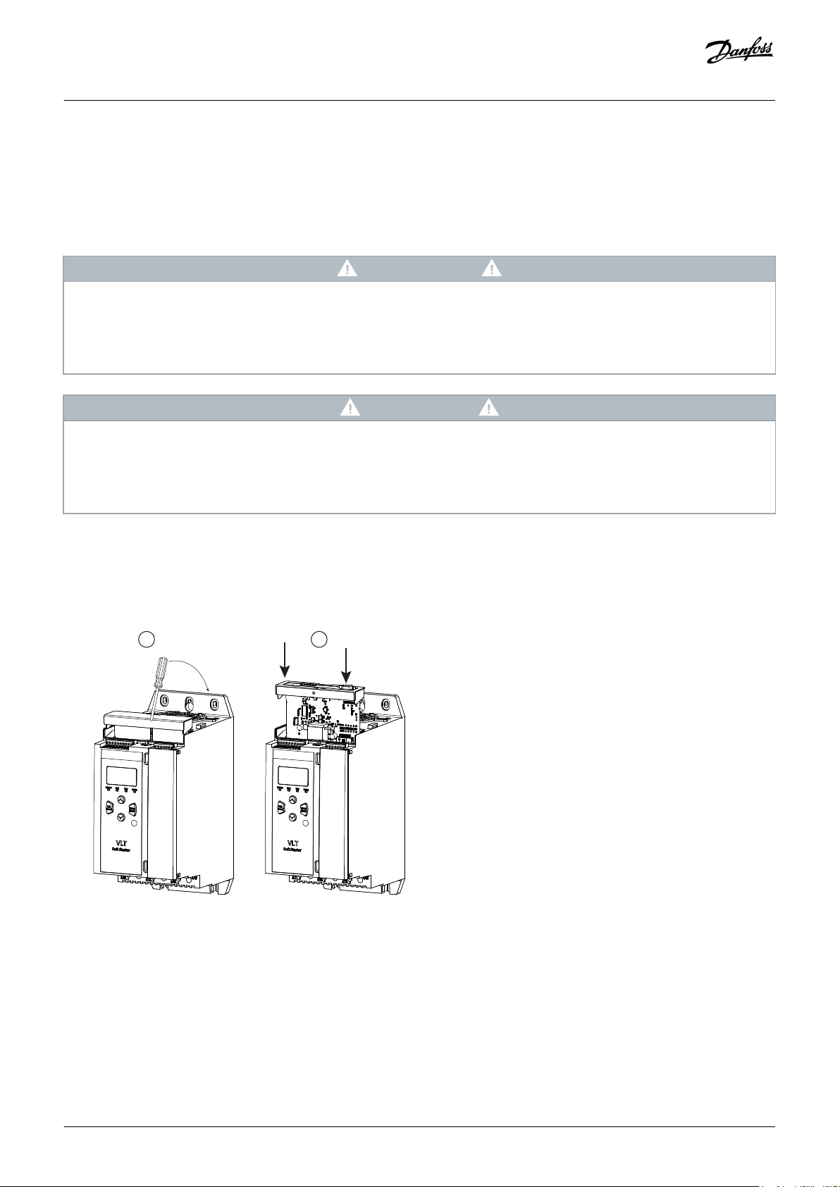
2 Installation
2.1 Installing the Expansion Card
Context:
WARNING
SHOCK HAZARD
The soft starter contains dangerous voltages when connected to mains voltage. Attaching or removing accessories when the
soft starter is connected to mains may cause death or serious injury.
Isolate the soft starter from mains voltage before attaching or removing accessories.
-
CAUTION
RISK OF INJURY AND EQUIPMENT DAMAGE
Inserting foreign objects or touching the inside the soft starter while the expansion port cover is open may endanger
personnel, and can damage the soft starter.
Be careful when installing the expansion cards and make sure not to touch the inside the soft starter.
-
Installation
Procedure
1. Push a small flat-bladed screwdriver into the slot in the center of the expansion port cover and ease the cover away from the soft
starter.
2. Line up the card with the expansion port. Gently push the card along the guide rails until it clicks into the soft starter.
2 | Danfoss A/S © 2018.06
AN265232431650en-000101 / 175R1177
Page 3
e77ha740.10
Installation guide | Remote VLT® Control Panel LCP 601 and
Mounting Kit
Installation
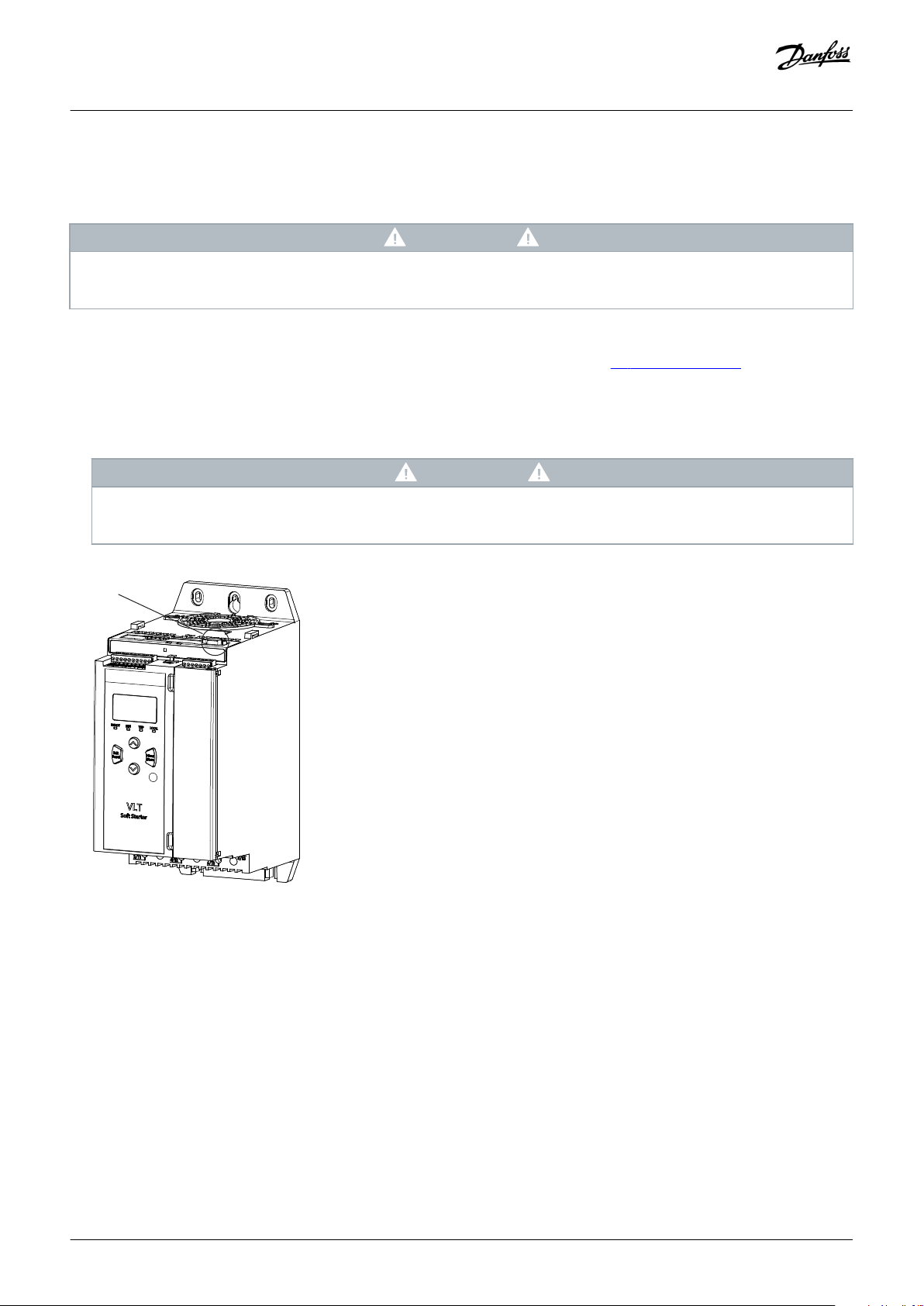
2.2 Installing the Remote VLT® Control Panel LCP 601
Context:
NOTICE
The remote VLT® Control Panel LCP 601 can be safely connected or removed while the soft starter is running. It is not necessary
to remove mains or control voltage.
Procedure
1. Measure and drill 4 holes for the mounting screws and 2 holes for the DB9 connector, see 2.4 Mounting Diagram.
2. Apply the foam gasket to the back of the LCP.
3. Align the LCP over the holes and screw in place. Tighten the screws so that the foam gasket is compressed to half its original
thickness (torque approximately 1 Nm (8.8 in-lb)).
NOTICE
If the screws are too long, the gasket does not provide IP65 protection. Overtightening the screws can damage the LCP,
gasket, or panel.
4. Plug the cable into the LCP and the soft starter.
5. Press the faceplate onto the front of the LCP.
2.3 Control via the Remote VLT® Control Panel LCP 601
The soft starter only accepts start and reset commands from the remote VLT® Control Panel LCP 601 if parameter 1A Command Source is
set to Remote Keypad.
Danfoss A/S © 2018.06
AN265232431650en-000101 / 175R1177 | 3
Page 4

READY RUN TRIP
LOCAL
RESET
LOGS
Alt
GRAPH
TOOLS
CMD
MENU
MENU
STORE
BACK
e77ha716.10
1
2
3
4
5
6
Installation guide | Remote VLT® Control Panel LCP 601 and
Mounting Kit
Installation
1 Four-line display for status and programming details.
3 Menu
navigation
keys:
Back: Exit the
menu or
parameter,
or cancel a
parameter
change.
Menu/Store:
Enter a menu
or parameter,
or save a
parameter
change.
5 Local control keys.
Illustration 1: Remote LCP
If the commissioning menu is open on the built-in LCP, the soft starter ignores all commands from the remote LCP except stop
commands.
Arrow keys:
Scroll to the
next or previous
menu or
parameter,
change the
setting of the
current
parameter, or
scroll through
the status
screens.
2 Status LEDs.
4 Shortcut to the command source menu in Set-up Tools.
6 Shortcut keys
for quick
access to
common tasks:
NOTICE
Logs:
Open the
Logs
Menu.
Graph: Select
which graph to
view, or pause/
restart the graph
(hold longer than
0.5 s).
Tools:
Open the
Set-up
Tools.
4 | Danfoss A/S © 2018.06
AN265232431650en-000101 / 175R1177
Page 5

Installation guide | Remote VLT® Control Panel LCP 601 and
Mounting Kit
NOTICE
The remote LCP can be safely connected or removed while the soft starter is running. It is not necessary to remove mains or
control voltage.
NOTICE
If parameter 1A Command Source is set to Remote LCP, removing the remote LCP causes a trip.
2.4 Mounting Diagram
Drill 4 mounting holes for screws (1 in each corner) and 2 holes for the DB9 connector.
NOTICE
The image is not to scale. Dimensions are given with the faceplate removed.
Installation
Danfoss A/S © 2018.06
AN265232431650en-000101 / 175R1177 | 5
Page 6

e77ha613.11
68 mm (2.7 in)
62 mm (2.45 in)
13 mm (0.5 in)
13 mm (0.5 in)
136 mm (5.35 in)
142 mm (5.6 in)
Installation guide | Remote VLT® Control Panel LCP 601 and
Mounting Kit
Installation
Illustration 2: Drilling Template
6 | Danfoss A/S © 2018.06
AN265232431650en-000101 / 175R1177
Page 7

e77ha614.11
Installation guide | Remote VLT® Control Panel LCP 601 and
Mounting Kit
Installation
1 Faceplate
3 Jack screw
5 Spring washer
7 VLT® Control Panel LCP 601
9 Panel
Illustration 3: Exploded View
2 Screw
4 Flat washer
6 Nut
8 Gasket
10 Cable
Page 8

Danfoss can accept no responsibility for possible errors in catalogues, brochures and other printed material. Danfoss reserves the right to alter its products without notice. This also applies to products
already on order provided that such alterations can be made without subsequential changes being necessary in specifications already agreed. All trademarks in this material are property of the respective
companies. Danfoss and the Danfoss logotype are trademarks of Danfoss A/S. All rights reserved.
Danfoss A/S
Ulsnaes 1
DK-6300 Graasten
vlt-drives.danfoss.com
Danfoss A/S © 2018.06 MI15E102
*MI15E102
AN265232431650en-000101/ 175R1177
*
 Loading...