

Voltage [V]
Power range [kW (hp)]
Minimum waiting time (minutes)
3x200
0.25–3.7 (0.33–5)
4
3x200
5.5–11 (7–15)
15
3x400
0.37–7.5 (0.5–10)
4
3x400
11–90 (15–125)
15
3x600
2.2–7.5 (3–10)
4
3x600
11–90 (15–125)
15
Voltage [V]
Power range [kW (hp)]
Minimum waiting time (minutes)
3x400
0.37–7.5 (0.5–10)
4
3x400
11–90 (15–125)
15
3x400
110–315 (150–450)
20
Installation Guide
VLT® Control Panel LCP
1 Introduction
1.1 Description
This Installation Guide explains how to install the LCP for VLT® HVAC Basic Drive FC 101 and VLT® Flow Drive FC 111.
1.2 Item Supplied
•
VLT® Control Panel LCP 32 (ordering number: 132B9221).
•
VLT® Control Panel LCP 31 (ordering number: 132B0200).
1.3 Safety Precautions
Only qualified personnel are allowed to install the LCP described in this Installation Guide.
For important information about safety precautions for installation, refer to the drive's Operating Guide.
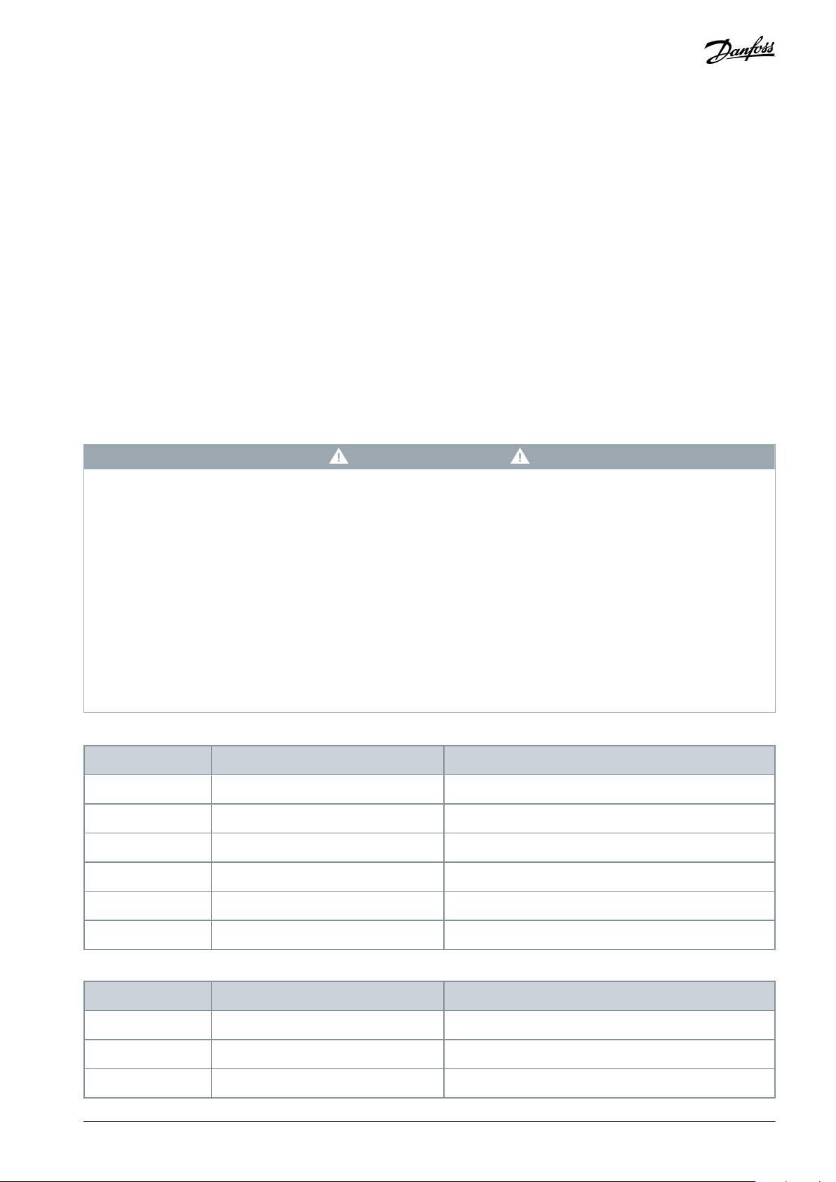
W A R N I N G
DISCHARGE TIME
The drive contains DC-link capacitors, which can remain charged even when the drive is not powered. High voltage can be
present even when the warning indicator lights are off.
Failure to wait the specified time after power has been removed before performing service or repair work could result in death or
serious injury.
Stop the motor.
-
Disconnect AC mains, permanent magnet type motors, and remote DC-link supplies, including battery back-ups, UPS, and
-
DC-link connections to other drives.
Wait for the capacitors to discharge fully. The minimum waiting time is specified in the table Discharge time and is also visible
-
on the nameplate on top of the drive.
Before performing any service or repair work, use an appropriate voltage measuring device to make sure that the capacitors
-
are fully discharged.
Table 1: Discharge Time for FC 101
Table 2: Discharge Time for FC 111
AN359636476228en-000201 / 130R0961 | 1Danfoss A/S © 2021.03
e30bu778.10
e30bu779.10
VLT® Control Panel LCP
Installation Guide
2 Installation
2.1 Mounting the LCP
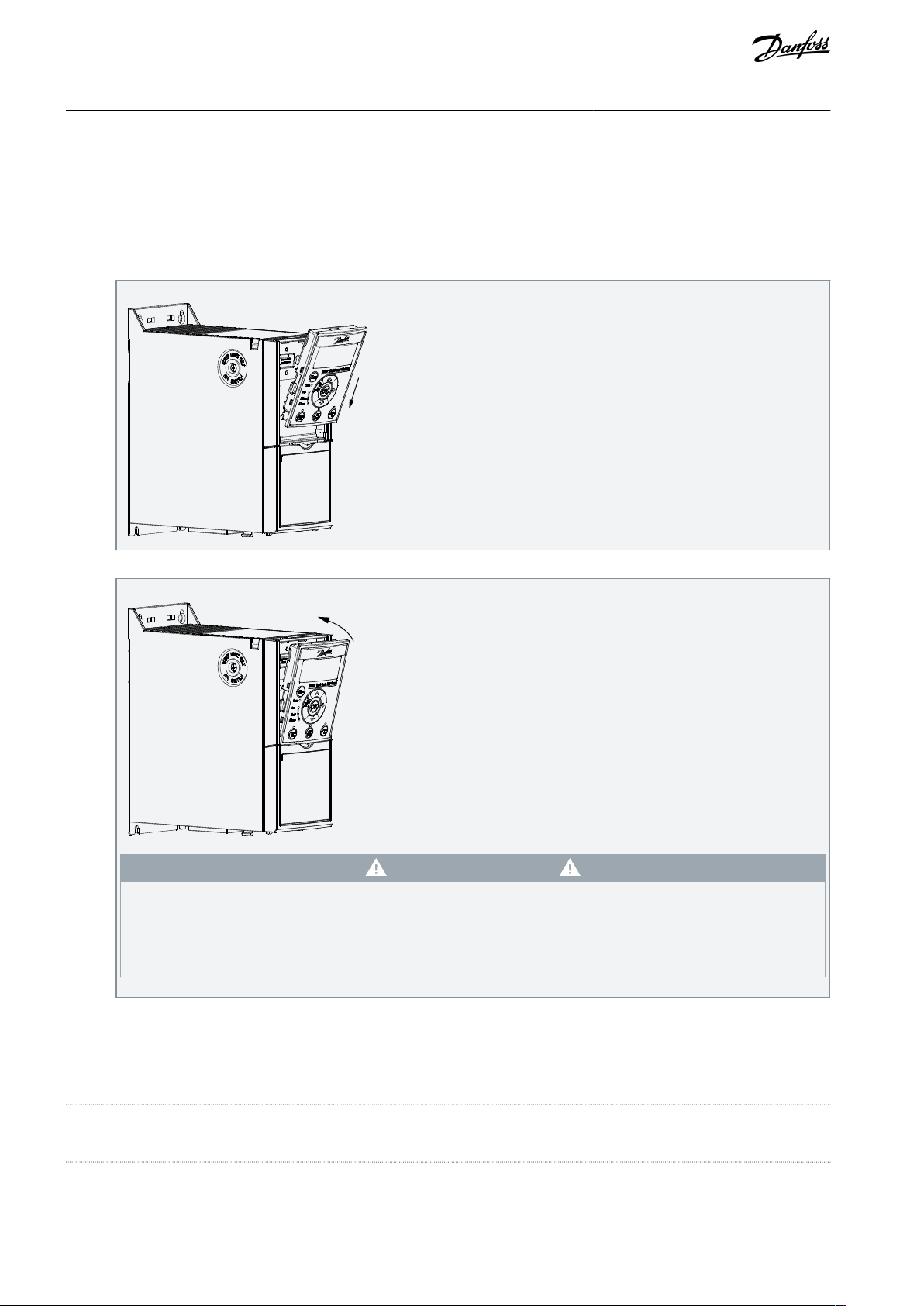
Taking LCP 32 as an example, the following steps describe how to install the LCP in a drive.
Procedure
1.
Position the bottom of the LCP in the drive.
Installation
2.
Push the top of the LCP into place.
When mounting the LCP, do not push or press too hard!
If it is not possible to mount the LCP in one easy operation directly on the drive, try to insert LCP before mounting
-
the terminal cover. When the terminal cover is removed and the drive is powered, do not touch the power terminals.
Danfoss A/S
Ulsnaes 1
DK-6300 Graasten
vlt-drives.danfoss.com
C A U T I O N
Danfoss can accept no responsibility for possible errors in catalogs, brochures, and other printed material. Danfoss reserves the right to alter its products without notice.
This also applies to products already on order provided that such alterations can be made without subsequential changes being necessary in specifications already
agreed. All trademarks in this material are property of the respective companies. Danfoss and the Danfoss logotype are trademarks of Danfoss A/S. All rights reserved.
*130R0961*
AN359636476228en-000201 / 130R09612 | Danfoss A/S © 2021.03
*M0027201*
 Loading...