

Page 1
Programming Guide
VLT® Condition-based Monitoring
VLT® FC Series
vlt-drives.danfoss.com
Page 2

Page 3

VLT® Condition-based Monitoring
Programming Guide
Contents
1
Before you begin 5
1.1
Introduction to the Programming Guide 5
Reading the parameter table 5
1.2
2
Introduction to Condition-based monitoring 7
2.1
System Requirements and Compatibility 7
2.2
Ordering Condition-based Monitoring in drives 9
2.2.1
Ordering Condition-based monitoring License From Factory 9
2.2.2
Ordering Condition-based Monitoring in Existing VLT Drive Using MCT-10 9
2.2.3
Enabling Condition-based Monitoring Features 11
2.3
Overview on Condition-based Monitoring 11
2.4
Condition-based Monitoring Workow 12
2.4.1
Step 1: Baseline Conguration 12
Contents
2.4.2
Step 2: Sensor Conguration (Optional) 13
2.4.3
Step 3: Threshold Calculation 13
2.4.4
Step 4: Alarms and Warnings 13
3
Examples of Condition-based Monitoring Functions 15
3.1
Example 1: Motor Stator Winding Monitoring 15
3.2
Example 2: Load Envelope 15
3.3
Example 3: Vibration Monitoring 16
4
Commissioning of Condition-based Monitoring 17
4.1
Commissioning Overview 17
4.2
Commissioning using MCT-10 Condition-based Monitoring Plug-in 17
4.3
Recommended Parameter Set-up using LCP or MCT-10 22
4.4
Threshold Conguration Guidelines 24
5
Fieldbus Integration for Condition-based Monitoring 25
5.1
Fieldbus Integration - Options and Parameters 25
6
Parameter Descriptions 29
6.1
Parameter Group 45 -** Condition-based Monitoring 29
6.2
Parameter Group 46-** CBM Monitoring Conguration 39
6.3
Parameter Group 47 -** CBM Baseline Data 45
7
Appendix 49
7.1
Motor Stator Windings 49
7.1.1
Alarm 510, Motor Stator Winding Alarm 49
AU310741645108en-000201/130R0901 | 3Danfoss A/S © 2020.10
Page 4

VLT® Condition-based Monitoring
Programming Guide
7.1.2
Warning 510, Motor Stator Winding Warning 1 49
7.1.3
Warning 500, Motor Stator Winding Warning 2 49
7.2
Vibration Monitoring 49
7.2.1
Alarm 512, Vibration Monitoring Alarm 49
7.2.2
Warning 512, Vibration Monitoring Warning 1 49
7.2.3
Warning 502, Vibration Monitoring Warning 2 49
7.3
Load Envelope 49
7.3.1
Alarm 511, Load Envelope Alarm 49
7.3.2
Warning 511, Load Envelope Warning 1 50
7.3.3
Warning 501, Load Envelope Warning 2 50
Contents
AU310741645108en-000201/130R09014 | Danfoss A/S © 2020.10
Page 5
2
5
6
1
3
4
e30bu346.10
VLT® Condition-based Monitoring
Programming Guide
Before you begin
1 Before you begin
1.1 Introduction to the Programming Guide
Introduction
This chapter describes the purpose of the programming guide, intended audience, disclaimer, safety conventions and additional
resources.
Purpose of this Programming Guide
This programming guide provides information on working with Condition-based monitoring parameters on the VLT® FC series.
It provides an overview of parameters and value ranges for operating the drive. Installation and operating instructions are not in
scope of this programming guide.
Intended Audience
The intended audience of the programming guide is trained personnel, automation engineers and programmers with experience in
operating with parameters and basic knowledge of Danfoss AC drives.
Safety Symbols
The following symbols are used in this manual:
D A N G E R
Indicates a hazardous situation which, if not avoided, will result in death or serious injury.
W A R N I N G
Indicates a hazardous situation which, if not avoided, could result in death or serious injury.
C A U T I O N
Indicates a hazardous situation which, if not avoided, could result in minor or moderate injury.
N O T I C E
Indicates information considered important, but not hazard-related (for example, messages relating to property damage).
Additional Resources
Additional resources are available to help you understand related information.
Technical documentation for various product options is available via the Danfoss home page in the Service and Support/Documen-
tation section.
1.2 Reading the parameter table
This programming guide includes parameter and options tables. These descriptions explain how to read the parameter and options
tables.
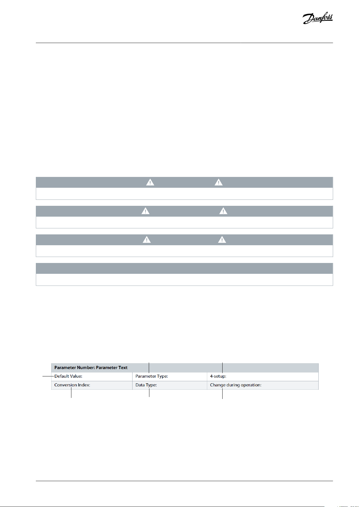
Illustration 1: Parameter Table
1 indicates the value set in factory.
2 indicates whether the parameter type is option or range.
3 indicates the manner of parameter set-ups. All setups means that the parameter can be set individually in each of the 4 setups. For
example, 1 single parameter can have 4 dierent data values. 1 setup indicates that the data value is the same in all setups.
4 refers to the conversion index. Parameter values are transferred as whole numbers only. Conversion factors are therefore used to
transfer decimals. If a value is transferred as 100 and a conversion index of -1, the real value is 10.0.
5 indicates the dierent data types for the parameters.
AU310741645108en-000201 / 130R0901 | 5Danfoss A/S © 2020.10
Page 6

Conversion index
Conversion factor
100175
3600000
74
36007060671/6061000000
5
100000
4
10000
3
1000210011001-10.1-20.01-30.001
-4
0.0001
-5
0.00001
-6
0.000001
Data type
Description
Type2Integer 8
Int83Integer 16
Int164Integer 32
Int325Unsigned 8
Uint8
6
Unsigned 16
Uint16
7
Unsigned 32
Uint32
9
Visible string
VisStr
33
Normalized value 2 bytes
N235Bit sequence of 16 boolean variables
V254Time dierence w/o date
TimD
VLT® Condition-based Monitoring
Programming Guide
6 indicates whether the parameter value can be changed while the frequency converter is in operation. False indicates that the
frequency converter must be stopped before a change can be made.
Table 1: Conversion Table
Before you begin
Table 2: Data type
AU310741645108en-000201 / 130R09016 | Danfoss A/S © 2020.10
Page 7
VLT® Product
Minimum Software Compatibility Version
VLT® HVAC Drive FC 102
5.70
VLT® Refrigeration Drive FC 103
2.70
VLT® AQUA Drive FC 202
3.80
VLT® Automation Drive FC 302
8.60
VLT® Motion Control Tool MCT 10
5.11
Control card version
Compatibility
Identication of control card version
MKII
Yes
White USB
MKINoBlack USB
Control mode
Compatibility
VVC+
Yes
U/fNoFluxNoMotor type
Compatibility
Asynchronous
Yes
PM, non salient SPM
(1)
No
PM, salient IPM
(1)
No
SynRM
No
PMaSynRM
No
Filter name
Compatibility
Description
VLT® dU/dt Filter MCC 102
Yes
Baseline needs to be run with the lter.
When the lter is installed later, make sure a new baseline is generated.
VLT® Sine-Wave Filter MCC 101
Yes
VLT® All-Mode Filter MCC 201
Yes
VLT® Condition-based Monitoring
Introduction to Condition-based
Programming Guide
monitoring
2 Introduction to Condition-based monitoring
2.1 System Requirements and Compatibility
In order to enable Condition-based monitoring and eectively function, verify the following software compatibilty and system-requirements.
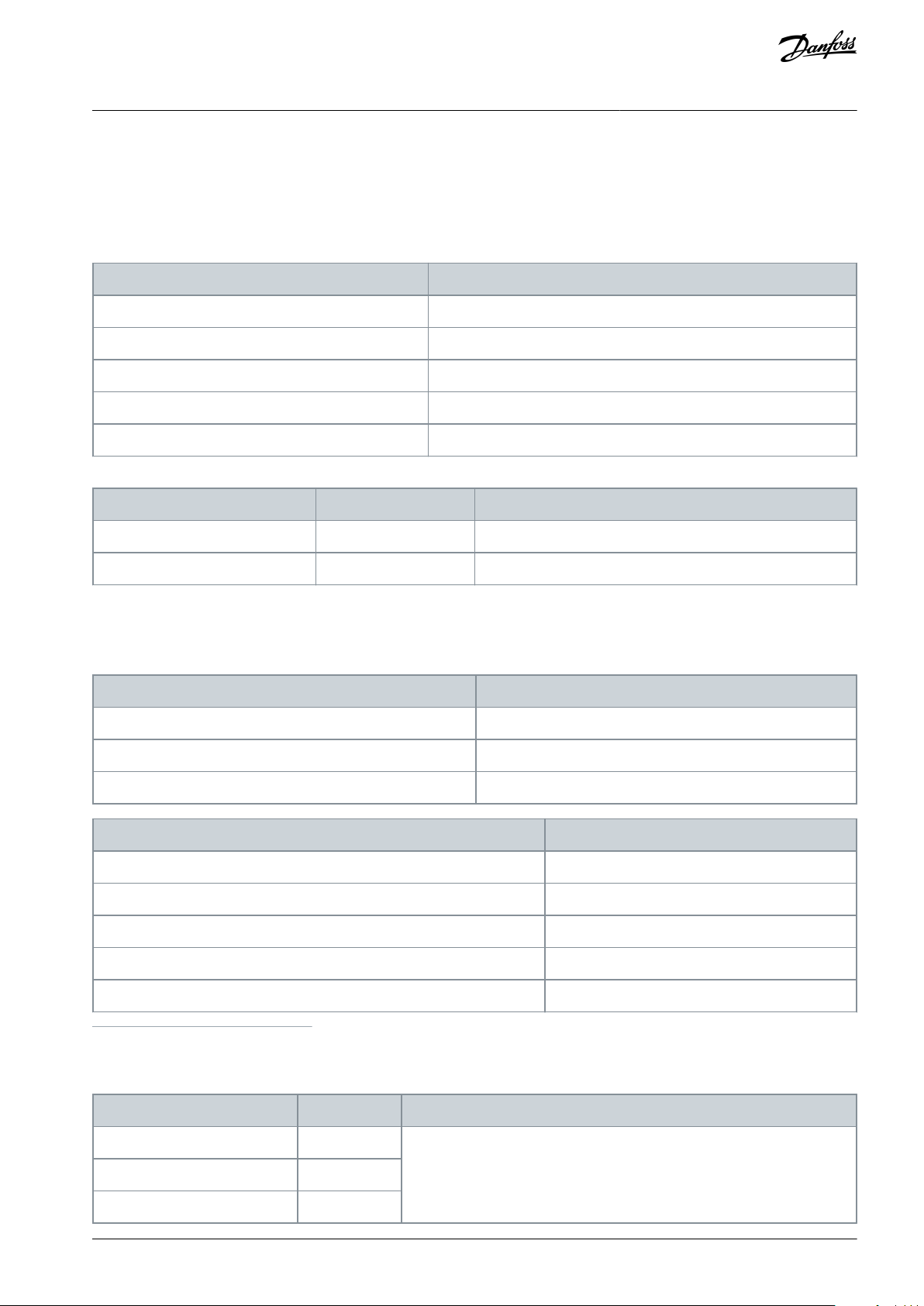
VLT® Products and Software compatibility for Condition-based monitoring
Control card compatibility for Condition-based monitoring
MKII control card is required to enable license code functions.
Contact local Danfoss Sales partner to determine the possibility of upgrading VLT® product with new control card, inorder to acti-
vate license code.
Stator Winding Monitoring Compatibilities
1
Ongoing implementation
Filters for stator winding monitoring function
Table 3: Compatible Filters for stator winding function
AU310741645108en-000201 / 130R0901 | 7Danfoss A/S © 2020.10
Page 8
Option type
Number of AI
Name of AI on the board
VLT® General Purpose I/O MCB 101
2
30/11, 30/12
VLT® Analog I/O MCB109
3
42/1, 42/3, 42/5
VLT® Sensor Input MCB 114
1
48/2
VLT(R) Programmable I/O MCB 115
3
X49/7+8, X49/9+10, X49/11+12
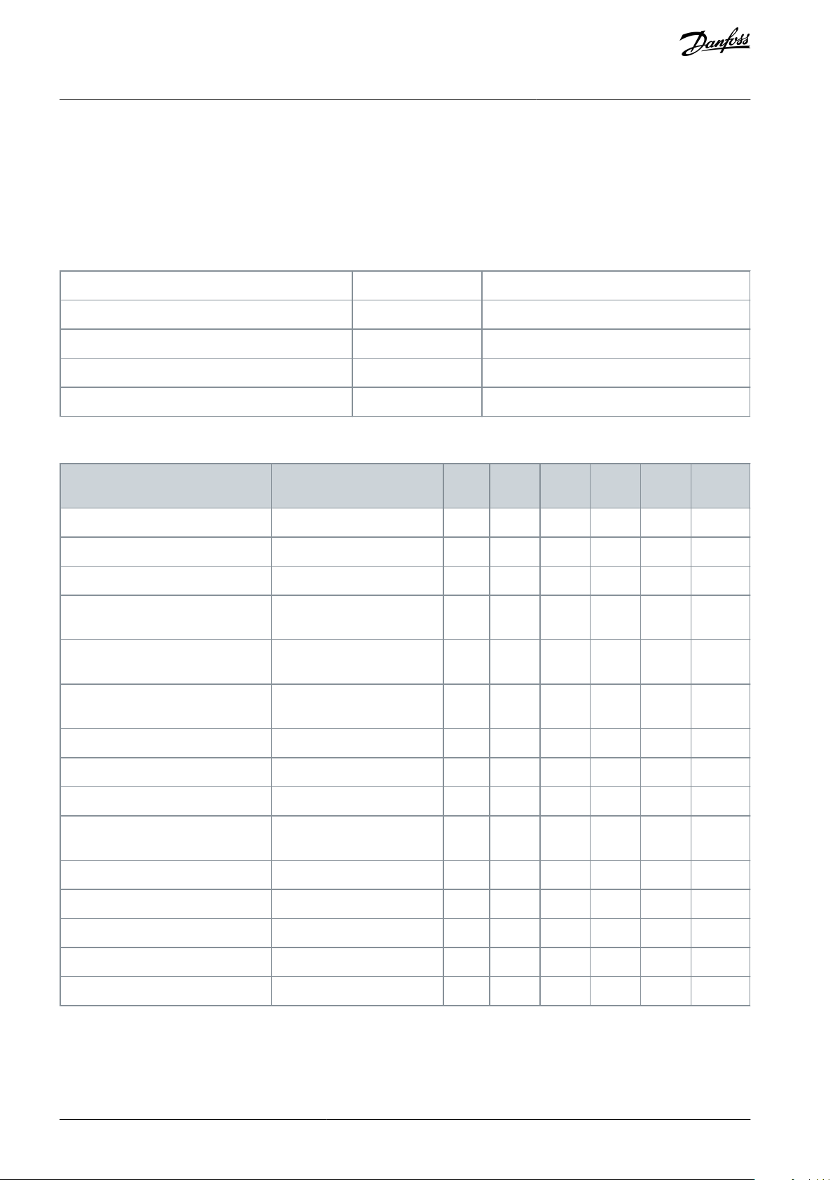
Option name
Status of Condition-based
monitoring support
Slot
FC 102
FC 103
FC 202
FC 302
FCD 302
Modbus RTU
Yes
RS485
xxxxx
BACNet MS/TP
No
RS485
x----
Metasys N2
Yes
RS485
x----
VLT® Probus DP MCA 101
Yes, with basic PDC value exchange.
AxxxxxVLT® Devicenet MCA 104
Yes, with basic PDC value exchange.
Ax-xx-VLT® CANOpen MCA 105
Yes, with basic PDC value exchange.
A---x
AK-LonWorks MCA 107 for ADAP-Kool
NoA-x---
LonWorks MCA 108
NoAxx---
VLT® BACNet MCA 109
NoAx----
VLT® Pronet MCA 120
Yes, with basic PDC value exchange.
Axxxx
x
VLT® Ethernet/IP MCA 121
YesAx-xxx
VLT® Modbus TCP MCA 122
YesAx-xxx
VLT® POWERLINK MCA 123
NoA---xx
VLT® EtherCAT MCA 124
YesA---xx
VLT® BACNet/IP MCA 125
YesAx----
VLT® Condition-based Monitoring
Introduction to Condition-based
Programming Guide
Sensor Congurations and Additional Analog Inputs
Condition-based programming use external sensors to obtain data. These external sensors are connected to AC Drive via Analog
Inputs (AI).
By default, the software enables the use of 2 sensors which is used for vibration monitoring in 2 directions. The software also allows
the addition of more sensors. Contact your local sales oce for more information.
To facilitate the addition of more sensors or when embedded analog inputs are used, congure the following options to extend the
analog inputs.
Table 4: Options and Analog Input Congurations
Fieldbus support in Condition-based Monitoring
Table 5: Fieldbus and Product Compatibility for Condition-based Monitoring
monitoring
In the above table:
•
x indicates the VLT® product supports the eldbus protocol.
•
- indicates the VLT® product does not support the eldbus protocol.
AU310741645108en-000201 / 130R09018 | Danfoss A/S © 2020.10
Page 9
Parameter number and name
License enabled from factory
License activated by customer (retrot)
Parameter 15-44 Ordered Typecode String
LX1X
SXXX
Parameter 15-45 Actual Typecode String
LX1X
LX1X
Parameter 50-00 License Installed
CBM
CBM
e30bi288.10
VLT® Condition-based Monitoring
Introduction to Condition-based
Programming Guide
For more information on eldbus integration with condition-based monitoring, see 5 Fieldbus Integration for Condition-based
Monitoring
For more information on the slots, see the VLT® product design guide
monitoring
2.2 Ordering Condition-based Monitoring in drives
Condition-based monitoring can be activated from the factory when ordering a new drive. The user can also activate conditionbased monitoring on existing VLT product using a license code.
When a license code is activated, parameters in parameter groups 45-**, 46-**, and 47-** reect the acceptance of license code.
These parameters are visible in LCP, MCT-10 or eld bus when license code is activated. For further information on specic license
codes for each VLT product, refer to Selection Guide.
Identifying License code information
Using the parameter group 15, the user can identify license code information.
2.2.1 Ordering Condition-based monitoring License From Factory
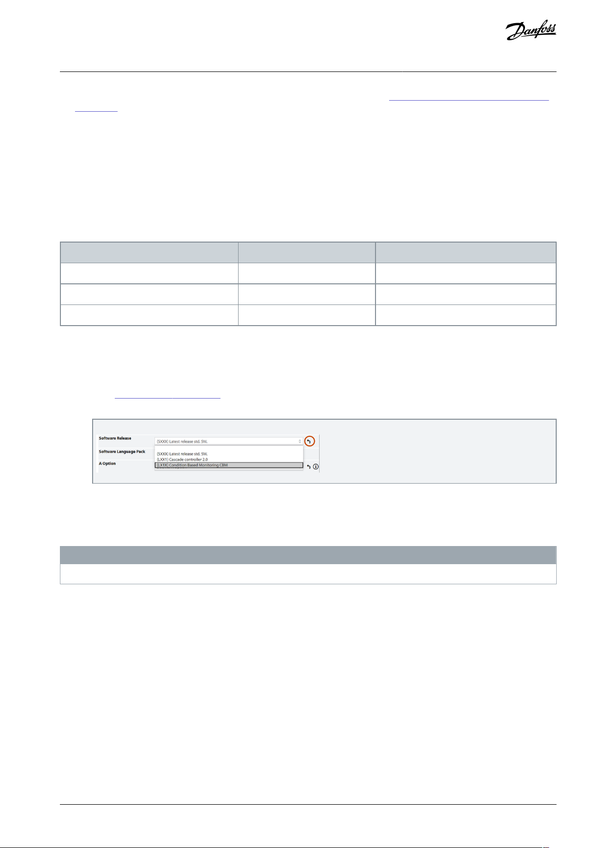
For the license code to be activated from the factory,the information has to be entered during product selection in the congurator.
Procedure
1.
Go to Danfoss Drives Congurator.
2.
Click the symbol corresponding to Software Release to open software release selections.
3.
Select LX1X Condition Based Monitoring CBM.
2.2.2 Ordering Condition-based Monitoring in Existing VLT Drive Using MCT-10
For retrot, licenses can be ordered from the regional sales oce. See Product Compatibility.
N O T I C E
License codes are unique to a single drive. The license code cannot be used on multiple drives.
The license code comprises of 16 alphanumeric characters in the format (XXXX-XXXX-XXXX-XXXX).
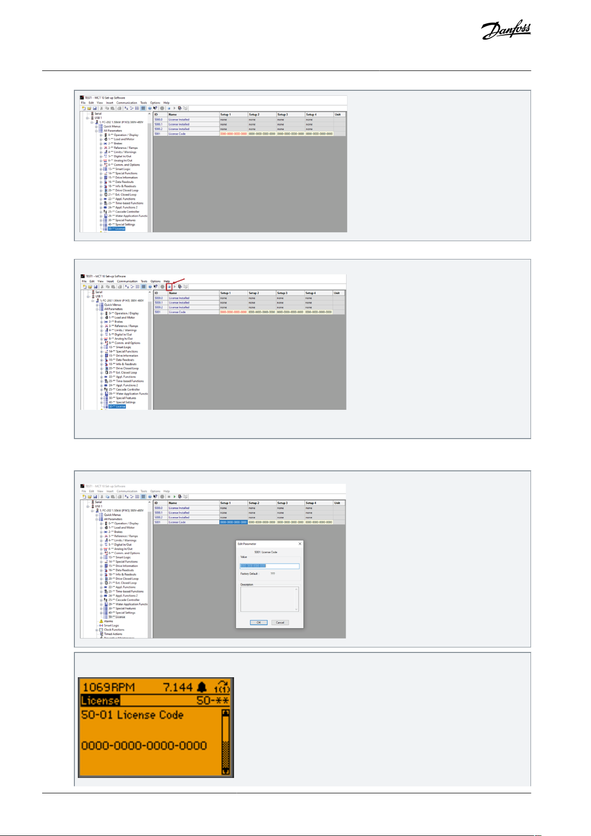
Procedure After receiving the license code, perform the following steps:
1.
Go to parameter group 50-** License group.
AU310741645108en-000201 / 130R0901 | 9Danfoss A/S © 2020.10
Page 10
e30bi438.10
e30bi439.10
e30bi440.10
e30bi287.10
VLT® Condition-based Monitoring
Programming Guide
2.
Stop polling. Press the button as shown in the gure.
Introduction to Condition-based
monitoring
Illustration 2: Stop Polling
3.
Go to parameter 50-01 License Code using the LCP or MCT-10.
4.
Enter the license code in parameter 50-01 License Code, instead of 0000-0000-0000-0000.
After entering the license code using the LCP, parameter 50-01 License Code shows the following information.
AU310741645108en-000201 / 130R090110 | Danfoss A/S © 2020.10
Page 11
e30bi286.10
ID
Name
Value
Description
45-00.0
Function
[1] Warning
Set the value for enabling stator monitoring.
45-00.1
Function
[1] Warning
Set the value for enabling load envelope.
45-00.2
Function
[1] Warning
Set the option for enabling vibration monitoring sensor 1.
45-00.3
Function
[0] O
Set the option for enabling vibration monitoring sensor 2.
VLT® Condition-based Monitoring
Introduction to Condition-based
Programming Guide
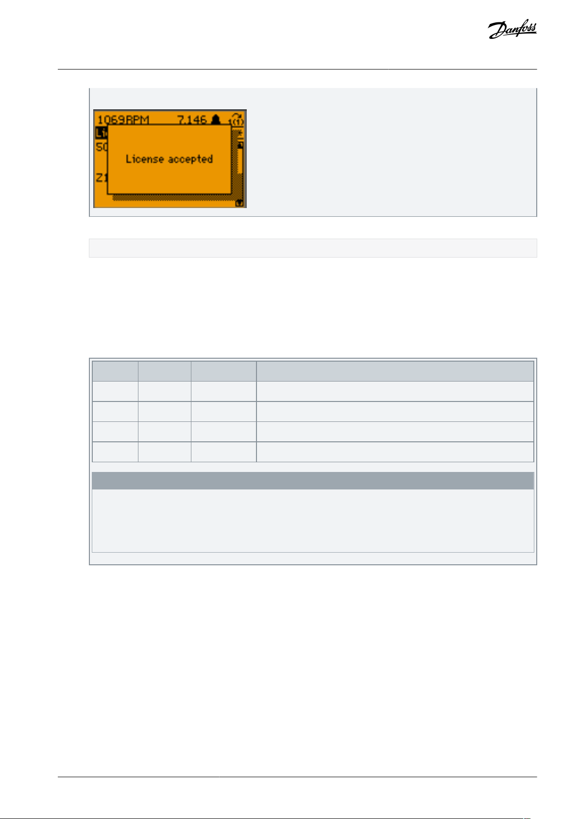
When the license is accepted by the drive, the LCP displays as shown below.
5.
Restart the drive and MCT-10 to activate the features.
The parameter groups 45, 46, and 47 are now available in LCP and in MCT-10.
monitoring
2.2.3 Enabling Condition-based Monitoring Features
In this recommendation, the scenario considered is to enable condition-based monitoring, when one sensor is installed on the
drive.
Procedure
1.
Go to Parameter Group 45 -** Condition-based Monitoring.
2.
Set the values to raise warnings for condition-based monitoring features, as described in the table.
N O T I C E
Make sure to congure parameter 45-00 Function inorder to generate [1] Warnings or [2] Warnings & Alarms, for proper
functioning of condition-based monitoring features.
The recommendation is to set [1] Warnings in parameter 45-00 Function. Setting [2] Warnings & Alarms in the param-
-
eter can cause the AC drive to trip, as alarms stops the drive.
2.3 Overview on Condition-based Monitoring
Condition-based monitoring in Danfoss VLT® drives enables to regularly check the condition and performance of the machine when
the drive is in service, and detects potential mechanical, motor, or application failures before the occurrence of an actual failure.
Benets of installing the condition-based monitoring rmware are as follows:
•
Reduces unexpected downtime
•
Eliminates unexpected halts in production
•
Optimizes maintenance
•
Reduction of spare part stock inventory
•
Optimizes production processes
Condition-based monitoring functions
Following are the 3 functions introduced in Condition-based monitoring. All the functions can be enabled at the same time for
monitoring the drive.
•
Motor stator winding monitoring: For this type of monitoring capability, an additional equipment is not required. The motor
current signature (inter-turn short circuit or unbalance in motor winding) is detected in drive. Damages caused by motor stator
AU310741645108en-000201 / 130R0901 | 11Danfoss A/S © 2020.10
Page 12
AC drive is installed
and commissioned
Baseline
Configuration
Threshold
Calculation
Threshold
Calculation
Monitoring
Monitoring
Initiate Baseline
(Measurement)
Sensor
Configuration
(optional)
Sensor
Configuration
(optional)
Baseline
Configuration
Initiate Baseline
(Measurement)
A
B
e30bu344.20
duration from few minutes upto 6 months
VLT® Condition-based Monitoring
Introduction to Condition-based
Programming Guide
winding isolation occurs over a period of time. When more winding turns are impacted, the overcurrent protection is activated
due to extensive heating and stops the motor
•
Load envelope: For this type of monitoring capability, an additional equipment is not required. Mechanical load of an application is monitored by comparing current load curve with expected load curve based on data gathered during commissioning.
During monitoring, overload and under-load deviations, which occur in applications, are detected.
•
Vibration monitoring: For this type of monitoring capability, the installation of vibration sensor(s) is required. Speed related
vibration (RMS) monitoring via external vibration sensor, detecting early signs of motor misalignments.
monitoring
N O T I C E
ISO10816 standard provides guidance for evaluating vibration severity for machines operating within 10–200 Hz of frequency
range. The standard shall be complied with before commissioning of vibration monitoring function.
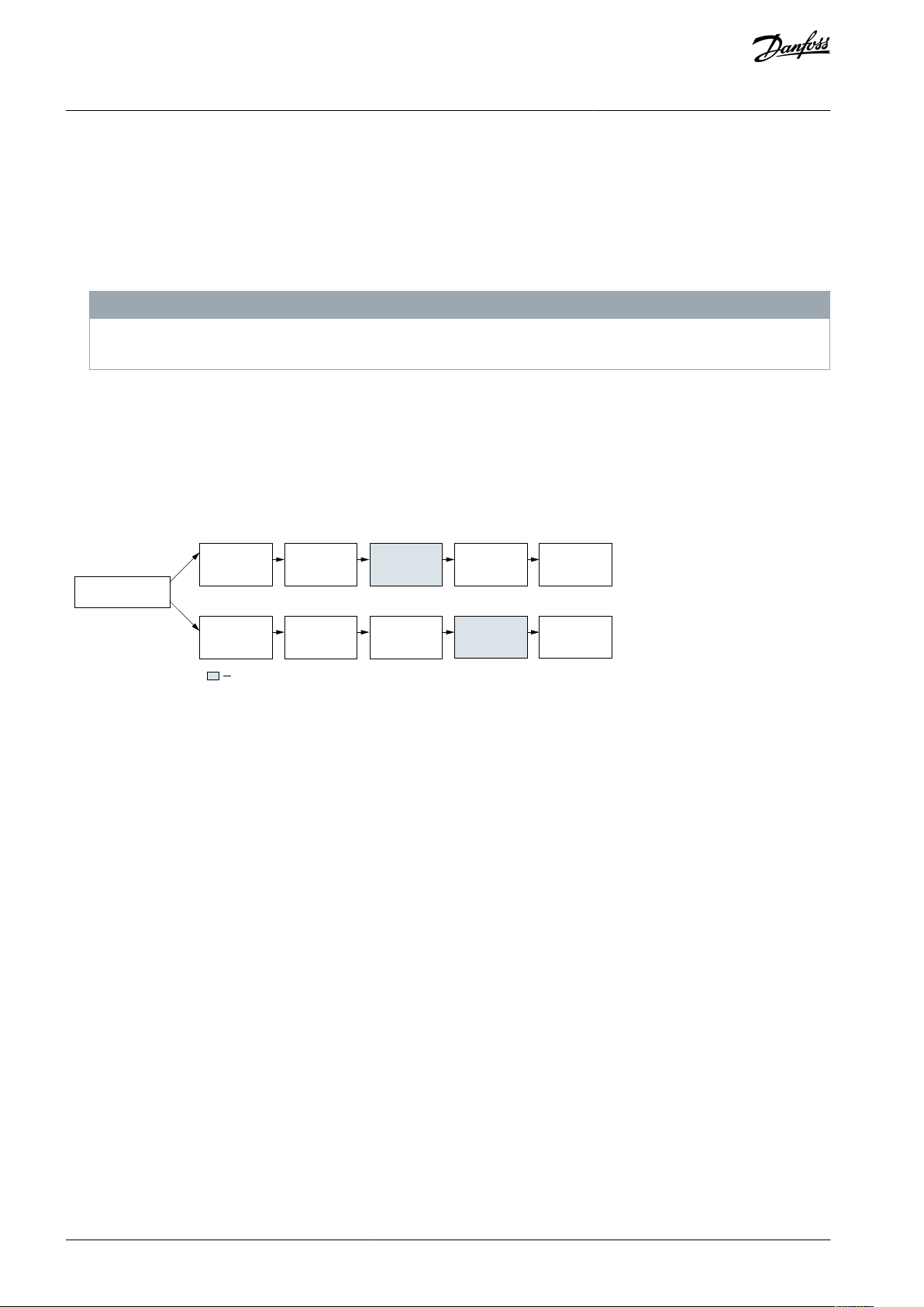
2.4 Condition-based Monitoring Workow
Before starting the commissioning of condition-based monitoring, make sure that the system is congured (installed and commissioned) for normal operation of the drive.
Depending on the user's requirement, commissioning condition-based monitoring allows the possibility to congure thresholds before or after initiating the baseline measurement. The process of obtaining baseline measurements after initiation takes upto 6
months.
The following illustration depicts the two ways to commission condition-based monitoring in a drive.
Illustration 3: Condition-based Monitoring Workow Overview
2.4.1 Step 1: Baseline Conguration
Baseline conguration is the 1st step and essential when commissioning a drive for condition-based monitoring. A baseline signature is required to determine any deterioration in the stator winding, load operating point, or vibration level of the application. The
baseline is recorded for each of the activated condition-based monitoring functions.
Following are the dierent ways to congure baseline:
•
Baseline Run: The drive takes control of the motor speed and creates a certain congurable speed prole and measures the
relevant signals. Depending on the load conditions, it is not always possible to execute the baseline run when the load does not
allow.
•
Online Baseline: In this method, the baseline is created by the drive without interrupting the operation of the drive and application. For the user-specied period of time, the relevant signals are gathered by the drive. This method provides a better representation of normal variation in the application.
•
Manual Baseline: In this method, the baseline values are manually congured into the drive.This method is relevant when the
baseline values are dened using prior experience and the values are congured in the drive.
As illustrated in the graph below, a baseline consists of 20 speed points which are captured based on the user-dened minimum
and maximum observation interval.
AU310741645108en-000201 / 130R090112 | Danfoss A/S © 2020.10
Page 13
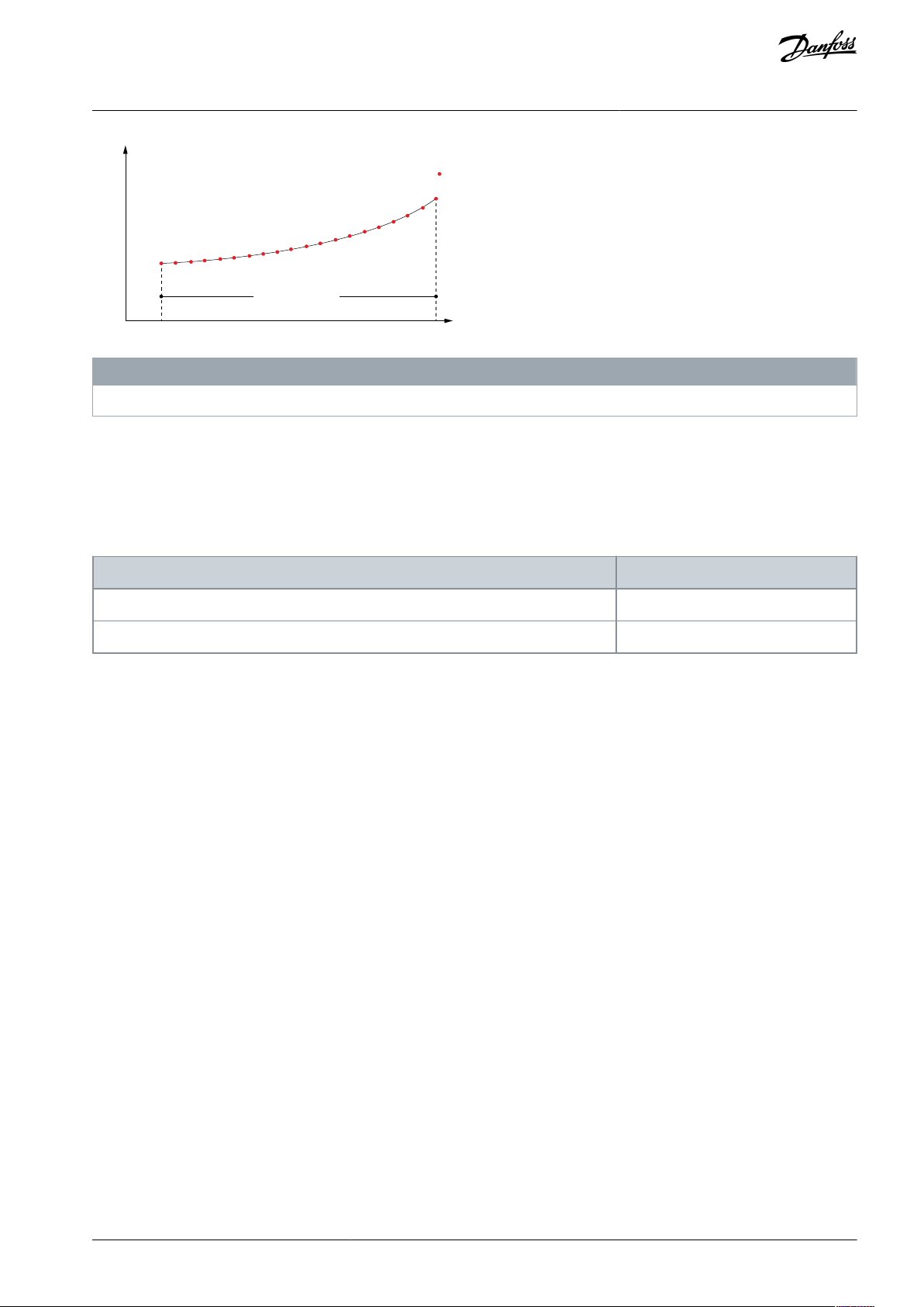
Speed point x 20
Value depending on feature
(vibration, load envelope, stator winding)
Observation area
Minimum
Frequency Maximum
e30bi292.10
Parameter ID and name
Example Values
Parameter 6-12 Terminal 53 Low Current
4 mA
Parameter 6-13 High Current
20 mA
VLT® Condition-based Monitoring
Introduction to Condition-based
Programming Guide
monitoring
N O T I C E
For new installations, ISO 20816 recommends a wear-in period before taking a baseline measurement.
2.4.2 Step 2: Sensor Conguration (Optional)
Vibration monitoring requires installation of an external vibration transmitter. The sensor is connected via analog input using for
example terminal 53 or terminal 54. When using these terminals make sure to scale correctly. For AI53 S201 to ON = mA and for AI54
switch S202 to ON = mA.
Make sure to congure the correct scaling using parameters in Parameter Group 6-1* Analog Input 1.
For example when terminal AI53 is used, congure the following:
If these terminals are in use for other equipment, it is possible to extend the analog input with extension options. For information on
extension options, see the Selection Guide.
2.4.3 Step 3: Threshold Calculation
Dening or setting the threshold values
In this step, the thresholds are dened. There are 3 methods of threshold calculation.
•
Absolute: This is the common method when the equipment values are already known. The threshold has a xed value irrespec-
tive of the measured baseline value. For example, when the operator knows the absolute limit for the equipment, an absolute
value is set for the alarm threshold. In case of vibration monitoring, the limit values described in standards such as ISO
10816/20816 can be used for the alarm threshold as an absolute value.
•
Oset: This method of setting threshold values requires understanding of the application and baseline values. The threshold
depends on the baseline value to which a user-dened oset is considered in the threshold conguration. Setting a very low or
high value leading to false positives is a risk when using this method. False settings can cause irresponsive monitoring, even in
the case of faults.
•
Factor: This method is easier to use when compared to oset, because it does not require in-depth application knowledge. The
threshold depends on the baseline value which is multiplied by a factor. For example, the threshold value may be 150% of the
baseline. Setting a very high threshold is a risk when using this method of threshold calculation.
2.4.4 Step 4: Alarms and Warnings
In condition-based monitoring, for each feature, the user can dene activation stages for warnings and alarms. The interpretation of
alarm and warning color codes are as follows:
Green: No alarms are indicated. Condition-based monitoring operations continue.
Yellow: First indication of warning-stage 1 alarm is visible. Stage 1 warning fault are also shown as Stage 1 Warning (S1). Notication
to users to plan for maintenance operations. In this stage, condition-based monitoring operations continue.
Orange: Clear indication of warning-stage 2 alarm is visible. Stage 2 warning fault are also shown as Stage 2 Warning (S2). Notica-
tion to users to act as soon as possible before the fault becomes critical.
Red: A critical alarm has occurred and condition-based monitoring operations has stopped.
AU310741645108en-000201 / 130R0901 | 13Danfoss A/S © 2020.10
Page 14

Threshold
Time
No Faults
Warning
Stage 1
Fault
Warning
Stage 2
Fault
Critical
Fault
e30bu345.10
VLT® Condition-based Monitoring
Introduction to Condition-based
Programming Guide
Illustration 4: Alarm and Warning Stages
For more information, see 7.1 Motor Stator Windings, 7.2 Vibration Monitoring, and 7.3 Load Envelope.
monitoring
AU310741645108en-000201 / 130R090114 | Danfoss A/S © 2020.10
Page 15
Current spectrum
Voltage spectrum
Machine
status
e30bi294.10
Current (A)
Frequency (Hz)
Upper threshold
Lower threshold
Baseline
-0.5
1
0.5
1.5
2
0
0 10 20 30 40 50
e30bi293.10
VLT® Condition-based Monitoring
Examples of Condition-based
Programming Guide
Monitoring Functions
3 Examples of Condition-based Monitoring Functions
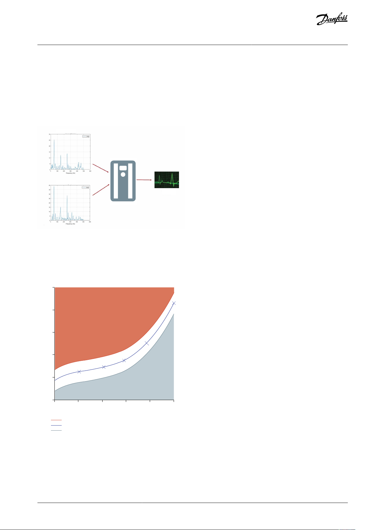
3.1 Example 1: Motor Stator Winding Monitoring
The AC drive provides variable magnitude of voltage and frequency to the stator terminal of connected 3-phase induction motors.
During healthy conditions of the motor with good stator winding insulation between inter-turn, the electrical signature shows consistency on the measurement. The electrical signature repeats the baseline value for repeated measurement.
However, in case of weakened insulation or inter-turn short circuit condition, the electrical signatures deviate from its original baseline values. The function withstands false positive in case of AC mains unbalance.
Illustration 5: Example of Motor Stator Winding Monitoring
3.2 Example 2: Load Envelope
The function monitors torque and speed prole of the application which is measured during the baseline measurement. The threshold conguration works similar to the other functions. Condition-based monitoring can detect underload and overload situations.
Hence, there are 2 warning stages for high side (overload scenario) and 2 warning stages for underload scenario.
Illustration 6: Load Envelope Example
AU310741645108en-000201 / 130R0901 | 15Danfoss A/S © 2020.10
Page 16
e30bi328.10
VLT® Condition-based Monitoring
Examples of Condition-based
Programming Guide
Monitoring Functions
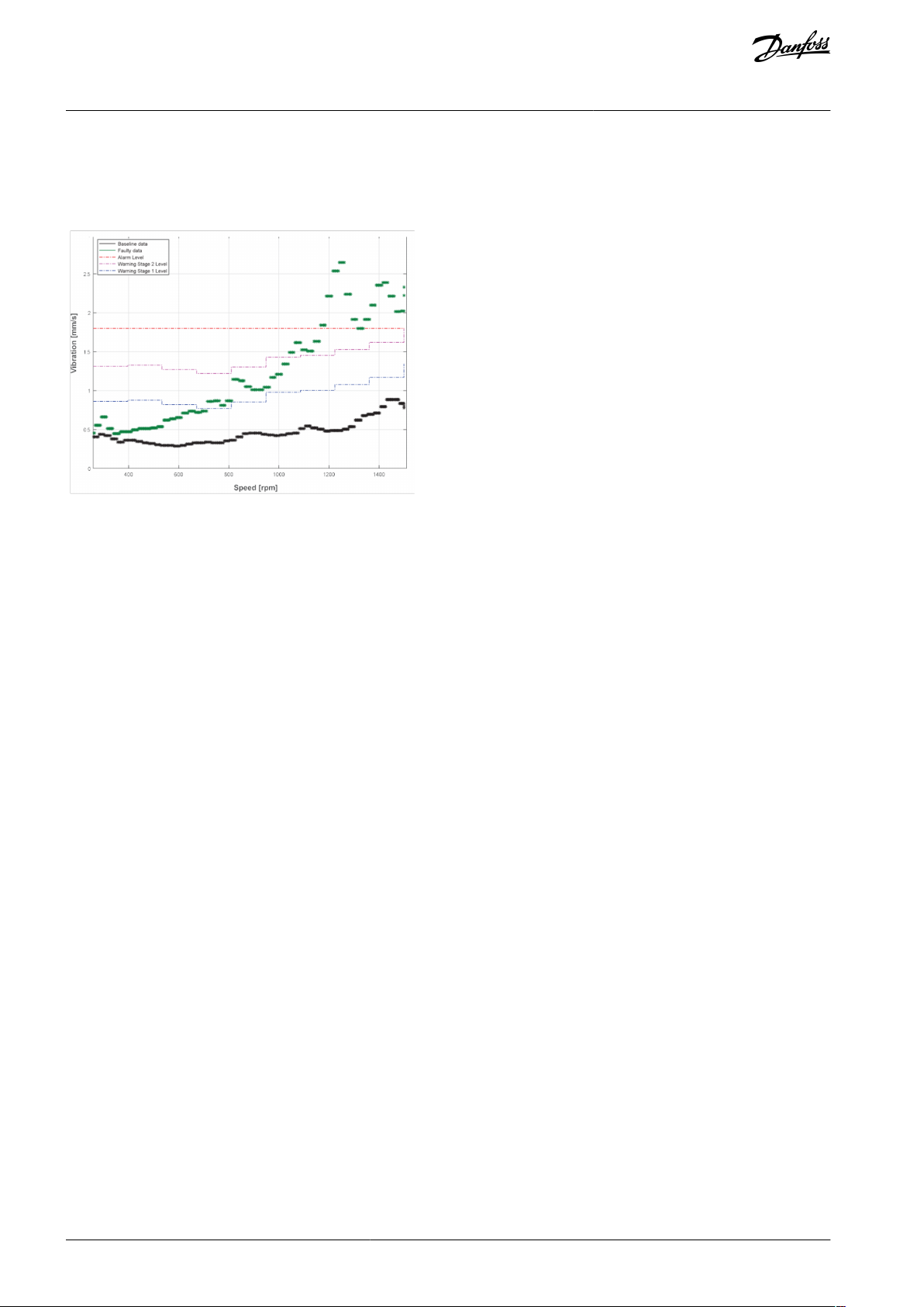
3.3 Example 3: Vibration Monitoring
The standard ISO 10816/20816 is the recommendation for vibration monitoring. The advantage, VLT® condition-based monitoring
provides, is the speed reference to the vibration level instead of an absolute level. The absolute level can mislead in lower levels of
the speed reference.
Illustration 7: Vibration Monitoring Example
AU310741645108en-000201 / 130R090116 | Danfoss A/S © 2020.10
Page 17

e30bi314.10
e30bi315.10
VLT® Condition-based Monitoring
Commissioning of Condition-based
Programming Guide
Monitoring
4 Commissioning of Condition-based Monitoring
4.1 Commissioning Overview
This chapter describes the commissioning of condition-based monitoring from baseline creation to monitoring the system. Before
performing commissioning steps, the assumption is the drive is installed and the license code for condition-based monitoring is
activated in the drive.
Danfoss Drives recommends to use MCT-10 Condition-based monitoring plug-in for commissioning of condition-based monitoring.
It is also possible to perform the commissioning using LCP. The following sections in this chapter, contain the following:
•
Commissioning using MCT-10 condition-based monitoring plug-in
•
Commissioning using LCP
•
Threshold Conguration Guidelines
Based on your MCT-10 version and activated license code, the plug-in is shown below.
Illustration 8: Condition-based Monitoring Plugin
4.2 Commissioning using MCT-10 Condition-based Monitoring Plug-in
Perform the following steps to set up conditiion-based monitoring in the drive.
•
Ensure MCT-10 version 5.11 or later is installed.
•
Ensure the desktop or laptop is connected to a powered-on AC drive with activated license code.
Note: The red highlight in the gure correspond to Danfoss recommended selections, and the blue highlight in the gure corre-
spond to application values. These values can vary based on application.
Procedure: The following are recommended steps to set-up condition-based monitoring:
1.
Select Online Baseline.
AU310741645108en-000201 / 130R0901 | 17Danfoss A/S © 2020.10
Page 18

e30bi316.10
e30bi317.10
Online baseline
Baseline run
2 Hours
1 Minute
4 Hours
2 Minutes
8 Hours
4 Minutes
1 Day
10 Minutes
2 Days
30 Minutes
5 Days
1 Hour
1 Week
2 Hours
2 Weeks
1 Month
2 Months
4 Months
6 Months
VLT® Condition-based Monitoring
Programming Guide
2.
Select minimum and maximum speed range using the slider or specify values in the textboxes.
The recommendation is to congure a speed window which relates to motor limitations. The motor speed is congured in
Parameter 4-11 Motor Speed Low Limit [RPM] and Parameter 4-13 Motor Speed High Limit [RPM].
Commissioning of Condition-based
Monitoring
Note: For advanced baseline settings, the minimum speed can be set as 30% of nominal speed as failures in low speed
measurement ranges are dicult to detect.
3.
Specify duration to capture baseline in Duration eld.
It is recommended to specify atleast 1 Week or more in the Duration eld.
Some of the duration options and corresponding baseline run values are specied below:
4.
Specify the speed band in the Speed step band, % eld.
AU310741645108en-000201 / 130R090118 | Danfoss A/S © 2020.10
Page 19

e30bi318.10
e30bi319.10
e30bi320.10
VLT® Condition-based Monitoring
Programming Guide
Note: Do not set speed band to 0%. 0% is for niche applications.
5.
Congure vibration sensor information in Sensor source and Sensor unit elds.
By default, no value is selected in the elds. If vibration sensors are not congured, press Next.
6.
Congure the minimum and maximum reference values in AI53 minimum input, AI53 maximum input, AI54 minimum input,
and AI54 maximum input. Press Next.
The recommended minimum and maximum values are 0 and 100 respectively, providing a reference from 0% to 100%.
Commissioning of Condition-based
Monitoring
Make sure to provide the correct scaling either 0-20 mA or 4-20 mA. See Sensor Conguration (Optional).
7.
Select an option to set method of baseline conguration. Press Next.
Note:
•
Duration to nish online baseline execution can occur within a period of 2 hours, 6 months, or one week.
•
Creating a baseline before conguring monitoring settings, requires an additional on-site visit to congure the threshold settings.
8.
To congure stator thresholds, congure settings in Stator tab.
9.
Select the Danfoss recommended options (highlight in red).
10.
Specify application values in Alarm and Warnings elds (highlight in blue).
Note: The values in the gure do not imply specic application values. Ensure to enter values which suit the application.
Following are the recommended application specic values for monitoring motor stator winding. See
4.4 Threshold Con-
guration Guidelines.
AU310741645108en-000201 / 130R0901 | 19Danfoss A/S © 2020.10
Page 20

e30bi321.10
e30bi322.10
e30bi323.10
VLT® Condition-based Monitoring
Programming Guide
11.
To congure load envelope threshold settings, press Load tab.
12.
Select the Danfoss recommended options (highlight in red).
13.
Specify the application-specic values in Alarms and Warnings elds (highlight in blue).
Note: The values in the gure does not imply specic application values. Ensure to enter values which suit the application.
Commissioning of Condition-based
Monitoring
14.
To congure vibration monitoring threshold congurations, pressVibration 1 tab.
15.
Select Danfoss recommended options (highlight in red).
16.
Specify application specic values in Alarm and Warnings eld (highlight in blue).
17.
Click Create Baseline.
AU310741645108en-000201 / 130R090120 | Danfoss A/S © 2020.10
Page 21

e30bi324.10
e30bi325.10
e30bi326.10
e30bi327.10
VLT® Condition-based Monitoring
Programming Guide
Commissioning of Condition-based
Monitoring
The progress bar indicates the remaining time for completion.
18.
To modify the duration during baseline creation, select required timeline from the Duration eld.
19.
To stop the baseline creation, click Stop Baseline Creation.
A timestamp is displayed in Started and Stopped eld, when parameter 0-70 Date and Time is congured.
AU310741645108en-000201 / 130R0901 | 21Danfoss A/S © 2020.10
Page 22

•••
•
ID
Name
Value
Parameter 45-00.0
Function (Stator Winding Monitoring)
Select [1] Warning to congure warning for stator winding monitoring.
Parameter 45-00.1
Function (Load Envelope)
Select [1] Warning to congure warning for load envelope.
Parameter 45-00.2
Function (Vibration Sensor 1)
Select [1] Warning to congure warning for vibration monitoring.
Parameter 45-00.3
Function (Vibration Sensor 2)
Select [0] Oto disable warnings or alarms for vibration sensor 2.
Parameter 45-24
Duration
Select [36] 1 week. This selection must be based on application.
Parameter 45-25
Online Speed Band
Select 5. This selection is application specic.
Parameter 45-26
Minimum Speed
Congure the same value as specied in Parameter 4-11
Parameter 45-27
Maximum Speed
Congure the same value as specied in Parameter 4-13
Parameter 45-20
Type
Select [2] Online Baseline.
Parameter number
Parameter name
Description and setting
Parameter 45-30.0
Baseline Statistics
Set [3] Mean +/-3 Standard Deviation
Parameter 45-31.0
Warning mode
[1] Oset
Parameter 45-34.0
Warning S2
For motor sizes 0 - <22 kW, specify 4.00.
For motor sizes >22kW, specify 2.00
Parameter 45-35.0
Warning S1
For motor sizes 0 - <22 kW, specify 2.00.
For motor sizes >22kW, specify 1.00
Parameter 46-11.0
Warning S2 time
Specify 10.00
Parameter 46-12.0
Warning S1 time
Specify 10.00
Parameter 45-60
Active Threshold
Specify 0.05
Parameter 45-61
Load Mode
For constant torque, specify [0] Absolute. For variable torque, specify [1] Oset.
Parameter 46-62
Load Threshold
For constant torque, specify 160. For variable torque, specify 2.
Parameter number
Parameter name
Description and setting
Parameter 45-32.0
Alarm Mode
Set [1] Oset.
VLT® Condition-based Monitoring
Programming Guide
4.3 Recommended Parameter Set-up using LCP or MCT-10
Step 1: Baseline Conguration
Commissioning of Condition-based
Monitoring
Result:
•
Parameter 45-21 shows the baseline status.
•
Parameter 45-22 shows the baseline progress.
Step 2: Threshold Conguration for Stator Winding Monitoring
To congure warnings, set parameter 45-00.0 to [1] Warning.
To congure alarms, set parameter 45-0.0 to [2] Alarm & Warning.
AU310741645108en-000201 / 130R090122 | Danfoss A/S © 2020.10
Page 23

•
•
•
Parameter number
Parameter name
Description and setting
Parameter 45-33.0
Alarm High
For motor sizes 0 - <22 kW, specify 6.00.
For motor sizes 22kW - <90kW, specify 4.00.
For motor sizes 90KW and above, specify 3.00.
Parameter 46-10.0
Alarm time
Specify 10.00
Parameter number
Parameter name
Description and setting
Parameter 45-30.1
Baseline Statistics
Set [3] Mean +/-3 Standard Deviation
Parameter 45-31.1
Warning mode
[1] Oset
Parameter 45-34.1
Warning S2 High
Specify 30. The value in this parameter is based on the application.
Parameter 45-35.1
Warning S1 High
Specify 20. The value in this parameter is based on the application.
Parameter 45-36.1
Warning S1 Low
Specify 20. The value in this parameter is based on the application.
Parameter 45-37.1
Warning S2 Low
Specify 30. The value in this parameter is based on the application.
Parameter 46-11.1
Warning S2 Time
Specify 10.00.
Parameter 46-12.1
Warning S1 Time
Specify 10.00.
Parameter 46-13.1
Interpolation Type
Specify [0] Linear.
Parameter number
Parameter name
Description and setting
Parameter 45-00.1
Function (Load Envelope)
Set [2] Alarm & Warning
Parameter 45-32.1
Alarm mode
[1] Oset
Parameter 45-33.1
Alarm high
Specify 60.
Parameter 45-38.1
Alarm low
Specify 60.
Parameter 46-10.1
Alarm time
Specify 10.00.
Parameter number
Parameter name
Description and setting
Parameter 45-30.2
Baseline Statistics
Set [3] Mean+/- Standard Deviation
Parameter 45-31.2
Warning mode
[1] Oset
Parameter 45-34.2
Warning S2 High
Specify 1.52.
Parameter 45-35.2
Warning S1 High
Specify 1.12.
Parameter 46-11.2
Warning S2 time
Specify 10.00.
Parameter 46-12.2
Warning S1 time
Specify 10.00.
Parameter 46-13.2
Interpolation Type
Set [1] Linear.
VLT® Condition-based Monitoring
Commissioning of Condition-based
Programming Guide
Step 3: Threshold Conguration for Load Envelope
To congure warnings, set parameter 45-00.1 to [1] Warning. Following are the recommended settings.
Monitoring
To congure alarm, set parameter 45-00.1 to [2] Alarm & Warnings. Following are the recommended settings. When alarms are raised,
the system operation is stopped.
Step 4: Vibration Threshold Conguration
AU310741645108en-000201 / 130R0901 | 23Danfoss A/S © 2020.10
Page 24

Parameter number
Parameter name
Description and setting
Parameter 45-00.1
Function (Load Envelope)
Set [2] Alarm & Warning
Parameter 45-32.1
Alarm mode
[1] Oset
Parameter 45-33.1
Alarm high
Specify 60.
Parameter 45-38.1
Alarm low
Specify 0.
Parameter 46-10.1
Alarm time
Specify 10.00.
Parameter
Alarm or Warning
Motor Size <
22kW
Motor Size 22kW to
<90 kW
Motor Size 90kW to
<355 kW
Motor Size 355kW
and higher
Parameter 45-33[0]
Alarm
(*)
6.00
4.00
3.00
3.00
Parameter 45-34[0]
Warning 2
4.00
2.00
2.00
2.00
Parameter 45-35[0]
Warning 1
2.00
1.00
1.00
1.00
Zone
Part 3 (Industrial Machines >15kW)
Part 7 (Pumps)
Part 1 (Rest)
Rigid
Flexible
Category 1 (critical)
Category 2 (less critical)
Small /
Rigid
Large /
Flexible
<300kW
>300kW
<300kW
>300kW
<200kW
>200kW
<200kW
>200kW
Zone C limit
(mm/s)
4.5
7.1
7.1116.6
7.6
8.5
9.5
4.5
14.7
Zone B limit
(mm/s)
2.8
4.5
4.5
7.145
5.1
6.1
1.8
9.3
Zone A limit
(mm/s)
1.4
2.3
2.3
3.5
2.5
3.5
3.2
4.2
0.71
4.5
Vibration
Warning
Oset
(mm/2)
0.7
1.125
1.125
1.775
1
1.25
1.275
1.525
0.45
2.325
O-set %
for level 1
Example
(1))
2.8
4.5
4.5
7.145
5.1
6.1
1.8
9.3
VLT® Condition-based Monitoring
Commissioning of Condition-based
Programming Guide
When parameter 45-00.1 is set to [2] Alarm & Warnings, following are the recommended settings. When alarms are raised, the system
operation is stopped.
Monitoring
4.4 Threshold Conguration Guidelines
Application specic input for monitoring Motor Stator Winding
Following are the recommendation congurations for dierent motor sizes to monitor motor stator winding.
*
By default, the setting should be disabled, as it stops system operation, when the event occurs.
Application specic input for Vibration Monitoring
Following are the recommendation congurations for dierent motor sizes to monitor motor stator winding.
Table 6: Recommendation for Vibration Monitoring
1)
sensor range 25mm/s
AU310741645108en-000201 / 130R090124 | Danfoss A/S © 2020.10
Page 25

Alarm or Warning overview
Alarm
number
(Parameter 18-55)
Warning
number
(Parameter 18-56)
Alarm
Word 3
(Parameter 16-97)
Warning
Word 3
(Parameter 16-98)
Description
Stator
Alarm
51031Warning S2
50030Warning S1
510
31
Max/min thresholds exceed
520
Congure the bit to show the alarm when maximum or
minimum threshold value is exceeded during automatic generation or manual change.
Load Envelope
Alarm high
51130Congure the bit to show load envelope high alarm.
Warning S2 high
50128Congure the bit to show load envelope high stage 2
warning.
Warning S1 high
51129Congure the bit to show load envelope high stage 1
warning.
Warning S1 low
51129Congure the bit to show load envelope low stage 1
warning.
Warning S2 low
50128Congure the bit to show load envelope low stage 2
warning.
Alarm Low
51130Congure the bit to show low alarm.
Max/min thresholds exceed
521
Congure the bit to show an alarm when the minimum
or maximum threshold value is exceeded during automatic generation or manual change.
Sensor 1
Alarm
51229Congure the bit to show an alarm for sensor 1.
Warning S2
50226Congure the bit to show a warning stage 2 for sensor
1.
VLT® Condition-based Monitoring
Fieldbus Integration for Condition-
Programming Guide
based Monitoring
5 Fieldbus Integration for Condition-based Monitoring
5.1 Fieldbus Integration - Options and Parameters
The parameter 16-03 Status Word indicates the overall alarm or warning which is triggered due to condition-based monitoring. Specic alarms and warnings are congured using parameter 16-97 Alarm Word 3 and parameter 16-98 Warning Word 3. To make sure
that the eldbus is integrated for viewing the alarms and warnings in condition-based monitoring, congure the following:
Alarm and Warning number with associated bits
The bit for each alarm and warning number is congured in parameter 18-55 Active Alarm Number, parameter 18-56 Active Warning
Numbers, parameter 16-97 Alarm Word 3, and parameter 16-98 Warning Word 3, as shown in the table. The alarm and warning number
is reected in the LCP.
N O T I C E
Parameter 18-55 Active Alarm Numbers and Parameter 18-56 Active Warning Numbers is only available in VLT® Automation Drive FC
302.
Table 7: Bits for conguring alarm and warning number
AU310741645108en-000201 / 130R0901 | 25Danfoss A/S © 2020.10
Page 26

Alarm or Warning overview
Alarm
number
(Parameter 18-55)
Warning
number
(Parameter 18-56)
Alarm
Word 3
(Parameter 16-97)
Warning
Word 3
(Parameter 16-98)
Description
Warning S1
51227Congure the bit to show a warning stage 1 for sensor
1.
Max/min thresholds exceed
522
Congure the bit to show an alarm when maximum or
minimum threshold values is exceeded during automatic generation or manual change
Sensor 2
Alarm
51328Congure the bit to show an alarm for sensor 2.
Warning S2
50324Congure the bit to show a warning stage 2 for sensor
2.
Warning S1
51325Congure the bit to show a warning stage 1 for sensor
2.
Max/min thresholds exceed
523
Congure the bit to show a warning when maximum
or minimum threshold values exceed during automatic
generation or manual change.
Sensor 3
Alarm
51427Congure the bit to show an alarm for sensor 3.
Warning S2
50422Congure the bit to show a warning stage 2 for sensor
3.
Warning S1
51423Congure the bit to show a warning stage 1 for sensor
3.
Max/min thresholds exceed
524
Congure the bit to show an alarm when maximum or
minimum threshold values is exceeded during automatic generation or manual change.
Sensor 4
Alarm
51526Congure the bit to show an alarm for sensor 4.
Warning S2
50520Congure the bit to show a warning stage 2 for sensor
4.
Warning S1
51521Congure the bit to show a warning stage 1 for sensor
4.
Max/min thresholds exceed
525
Congure the bit to show an alarm when maximum or
minimum threshold value is exceeded during automatic generation or manual change.
Bit
Hex
Dec
Alarm Word 3 in parameter 16-97
Warning Word 3 in parameter 16-98
011
Temperature input error
Temperature input error
122
Memory Modele Fault
VLT® Condition-based Monitoring
Programming Guide
Fieldbus Integration for Condition-
based Monitoring
Alarm and Warning Conversion
In the following table, the conversion for bit, hexadecimal, and decimal are listed for parameter 16-97 Alarm Word 3 and parameter
16-98 Warning Word 3.
Table 8: Alarm and Warning Conversion Table
AU310741645108en-000201 / 130R090126 | Danfoss A/S © 2020.10
Page 27

Bit
Hex
Dec
Alarm Word 3 in parameter 16-97
Warning Word 3 in parameter 16-98
244
Internal Fan Error
Internal Fan Warning
388
Sync. Fault
41016
ORM Fault
52032
Test MOC Function
64064
Probus Converter Invalid
Probus Converter time warning
7801288100
2569200
51210400
102411800
2048121000
4096132000
8192144000
16384
15
8000
32768
16
10000
65536
17
20000
131072
18
40000
262144
19
80000
524288
20
100000
1048576
Sensor 4 S2
21
200000
2097152
Sensor 4 S1
22
400000
4194304
Sensor 3 S2
23
800000
8388608
Sensor 3 S1
24
1000000
16777216
Sensor 2 S2
25
2000000
33554432
Sensor 2 S1
26
4000000
67108864
CBM Sensor 4 Alarm
Sensor 1 S2
27
8000000
134217728
CBM Sensor 3 Alarm
Sensor 1 S1
28
10000000
268435456
CBM Sensor 2 Alarm
CBM Load Envelope High/Low S2
29
20000000
536870912
CBM Sensor 1 Alarm
CBM Load Envelope High/Low S1
30
40000000
1073741824
CBM Load High/Low Alarm
CBM Motor Stator Winding S2
31
80000000
2147483648
CBM Motor Stator Winding Alarm
CBM Motor Stator Winding S1
VLT® Condition-based Monitoring
Programming Guide
Fieldbus Integration for Condition-
based Monitoring
PCD Parameters
In the section, the parameters relevant for conguring the dierent eldbus options are described. Within the array index of the
parameter, make sure to congure the option in order to setup condition-based monitoring via eldbus.
AU310741645108en-000201 / 130R0901 | 27Danfoss A/S © 2020.10
Page 28

Parameter 8-43
Parameter 8-43.0
Parameter 8-43.2
Parameter 8-43.3
FC
[1603] Status word
[1697] Alarm Word 3
[1698] Warning Word 3
Modbus RTU
Metasys N2
Parameter 9-16
Parameter 9-16.0
Parameter 9-16.2
Parameter 9-16.3
VLT Probus DP MCA 101
[1603] Status word
[1697] Alarm Word 3
[1698] Warning Word 3
VLT Pronet MCA 120
Parameter 10-12
Paramter 10-12.0
Paramter 10-12.2
Parameter 10-12.3
VLT Devicenet MCA 104
[1603] Status word
[1697] Alarm Word 3
[1698] Warning Word 3
Parameter 10-51
Parameter 10-51.0
Parameter 10-51.2
Parameter 10-51.3
VLT CANOpen MCA 105
[1603] Status word
[1697] Alarm Word 3
[1698] Warning Word 3
Parameter 12-22
Parameter 12-22.0
Parameter 12-22.2
Parameter 12-22.3
VLT Ethernet/IP MCA 121
[1603] Status word
[1697] Alarm Word 3
[1698] Warning Word 3
VLT Modbus TCP MCA 122
VLT POWERLINK MCA 123
VLT® Condition-based Monitoring
Programming Guide
Table 9: Fieldbus option using parameter 8-43 PCD Read Conguration
Table 10: Fieldbus option using parameter 9-16 PCD Read Conguration
Table 11: Fieldbus
Fieldbus Integration for Condition-
based Monitoring
Table 12: Fieldbus option using Parameter 10-51 Process Data Cong Read
Table 13: Fieldbus option using Parameter 12-22 Process Data Cong Read
AU310741645108en-000201 / 130R090128 | Danfoss A/S © 2020.10
Page 29

45-00: Function
Default Value:O
Parameter Type: Option
4-setup: 2 setup
Conversion Index: -
Data Type: Uint8
Change during operation: False
Options
Option
Name
Description
[0]ONotication is disabled.
[1]
Warning
Warning notications are triggered.
[2]
Alarm & Warning
Both alarm and warning notications are triggered.
Parameter ID
Description
45-00.0
Select the required option to enable stator winding monitoring.
45-00.1
Select the required option to enable load envelope
45-00.2
Select the required option to enable sensor 1 vibration.
45-00.3
Select the requred option to enable sensor 2 vibration.
Default Value: O
Parameter Type: Option
4-setup: 2setup
Conversion Index: -
Data Type: Uint8
Change during operation: False
Option
Name
Description
[0]*OStatus is disabled.
[1]OnShows current monitoring status.
[2]
Waiting For Baseline
Baseline computation is in progress.
45-10: Alarm High Threshold
Default Value:0%
Parameter Type: Range
4-setup: All set-up
VLT® Condition-based Monitoring
Programming Guide
Parameter Descriptions
6 Parameter Descriptions
6.1 Parameter Group 45 -** Condition-based Monitoring
In this parameter group, you can enable condition-based monitoring, dene units, baseline computation, input sources, view baseline status, and progress.
Parameter 45-00: Function
Table 14: Parameter 45-00
Set type of notication level and to enable monitoring of the drive.
Table 15: Options
Table 16: Parameter Index
Parameter 45-01: Status
Set the parameter to view current monitoring status.
Parameter 45-10: Alarm High Threshold
Table 17: Parameter 45-10
AU310741645108en-000201 / 130R0901 | 29Danfoss A/S © 2020.10
Page 30

45-10: Alarm High Threshold
Conversion Index: -
Data Type: Uint8
Change during operation: True
Parameter ID
Description
45-10.0
Stator Winding
45-10.1
Stator Winding Active
45-10.2
Stator Winding Load
45-10.3
Load Envelope
45-10.4
Sensor 1 Vibration
45-10.5
Sensor 2 Vibration
45-11: Warning S2 High Threshold
Default Value: 0
Parameter Type: Range [0 - 655.35 %]
4-setup: All setups
Conversion Index:
Data Type: Uint8
Change during operation: True
Parameter ID
Description
45-11.0
Stator Winding
45-11.1
Stator Winding Active
45-11.2
Stator Winding Load
45-11.3
Load Envelope
45-11.4
Sensor 1 Vibration
45-11.5
Sensor 2 Vibration
45-12: Warning S1 High Threshold
Default Value: 0
Parameter Type: Range [0 - 655.35 %]
4-setup: All setups
Conversion Index: -2
Data Type: Uint8
Change during operation: True
VLT® Condition-based Monitoring
Programming Guide
Set the maximum threshold limit. The drive triggers a notication when threshold limit is exceeded.
Table 18: Options
Parameter 45-11: Warning S2 High Threshold
Parameter Descriptions
Table 19: Parameter 45-11
Set the maximum threshold limit for warning stage 2 for the index. The drive triggers a warning notication when threshold limit is
exceeded.
Table 20: Parameter Index
Parameter 45-12: Warning S1 High Threshold
Table 21: Parameter 45-12
Set the maximum threshold limit for warning stage 1, in the parameter index. The drive triggers a warning notication when threshold limit is exceeded. Entering a value in the parameter indicates a user specied threshold limit.
AU310741645108en-000201 / 130R090130 | Danfoss A/S © 2020.10
Page 31

Parameter ID
Description
45-12.0
Stator Winding
45-12.1
Stator Winding Active
45-12.2
Stator Winding Load
45-12.3
Load Envelope
45-12.4
Sensor 1 Vibration
45-12.5
Sensor 2 Vibration
45-13: Actual Monitor Value
Default Value:0%
Parameter Type: N/A
4-setup: All setups
Conversion Index: -2
Data Type: Uint16
Change during operation: True
Parameter ID
Description
45-13.0
Stator Winding
45-13.1
Stator Winding Active
45-13.2
Stator Winding Load
45-13.3
Load Envelope
45-13.4
Sensor 1 Vibration
45-13.5
Sensor 2 Vibration
45-14: Warning S1 Low Threshold
Default Value:0%
Parameter Type: Range [0 - 655.35 %]
4-setup: All set up
Conversion Index: -2
Data Type: Uint8
Change during operation: True
Parameter ID
Description
45-14.0
Stator Winding
45-14.1
Stator Winding Active
45-14.2
Stator Winding Load
VLT® Condition-based Monitoring
Programming Guide
Table 22: Parameter Index
Parameter 45-13: Actual Monitor Value
Table 23: Parameter 45-13
Parameter Descriptions
Shows the current value of selected signal.
Table 24: Parameter Index
Parameter 45-14: Warning S1 Low Threshold
Table 25: Parameter 45-14
Set the minimum threshold limit for warning stage 1 notication in the parameter index. The drive triggers a notication when the
actual monitoring value falls below the minimum threshold limit.
Table 26: Parameter Index
AU310741645108en-000201 / 130R0901 | 31Danfoss A/S © 2020.10
Page 32

45-14.3
Load Envelope
45-14.4
Sensor 1 Vibration
45-14.5
Sensor 2 Vibration
45-15: Warning S2 Low Threshold
Default Value:0%
Parameter Type: Range [0 - 655.35 %]
4-setup: All setups
Conversion Index: -
Data Type: Uint8
Change during operation: True
Parameter ID
Description
45-15.0
Stator Winding
45-15.1
Stator Winding Active
45-15.2
Stator Winding Load
45-15.3
Load Envelope
45-15.4
Sensor 1 Vibration
45-15.5
Sensor 2 Vibration
45-16: Alarm Low Threshold
Default Value:0
Parameter Type: Range ()
4-setup: All setups
Conversion Index: -
Data Type: Uint16
Change during operation: True
Parameter ID
Description
45-16.0
Stator Winding
45-16.1
Stator Winding Active
45-16.2
Stator Winding Load
45-16.3
Load Envelope
45-16.4
Sensor 1 Vibration
45-16.5
Sensor 2 Vibration
VLT® Condition-based Monitoring
Programming Guide
Parameter Descriptions
Parameter 45-15: Warning S2 Low Threshold
Table 27: Parameter 45-15
Set the minimum threshold limit for warning stage 2 notication, in the parameter index. The drive triggers a warning stage 2 notication when the actual monitoring value falls below the threshold limit specied in the parameter.
Table 28: Parameter Index
Parameter 45-16: Alarm Low Threshold
Table 29: Parameter 45-16
Set the minimum threshold limit, in the parameter index. The drive triggers an alarm notication when the actual falls below the
minimum threshold limit.
Table 30: Parameter Index
Parameter 45–20: Type
AU310741645108en-000201 / 130R090132 | Danfoss A/S © 2020.10
Page 33

Default Value: O
Parameter Type: Option
4-setup: All setups
Conversion Index: -
Data Type: Uint8
Change during operation: True
Option
Name
Description
[0]*OBaseline computation type is not set.
[1]
Baseline
Run
Select the option when the application can operate from minimum to maximum speed in one sweep. On
enabling this option, the condition-based monitoring function sets speed points. On completion of baseline computation, the motor is ramped down to 0. The option can only operate when Hand On mode is set
via control panel.
[2]
Online
Baseline
Select the option in applications where baseline run cannot be utilized. In this type of baseline computation, the drive is controlled by the application baseline and speed points are recorded and saved during
the duration specied in Parameter 45-24 Duration. The option can only operate when Auto On mode is set
via control panel.
Default Value: Not Started
Parameter Type: Option
4-setup: All setups
Conversion Index: -
Data Type: Uint16
Change during operation: True
Option
Name
Description
[0]*
Not Started
-
[1]
Baseline Run running
-
[2]
Online Baseline running
-
[3]
Baseline Completed
-
[4]
Baseline Failed
-
Default Value: 0%
Parameter Type: [0-100%]
4-setup: All setups
Conversion Index: -
Data Type: Uint8
Change during operation: True
Default Value: Size related
Parameter Type: Option
4-setup: 2 setup
Conversion Index: -
Data Type: Uint8
Change during operation: False
Option
Name
Description
[0]
1 Min
-
[1]
2 Mins
-
VLT® Condition-based Monitoring
Programming Guide
Use the parameter to select type of baseline computation.
Parameter 45–21: Status
Parameter Descriptions
Shows the current status of baseline computation.
Parameter 45–22: Progress
Shows the progress of baseline computation. 0% indicates that the baseline computation is not started and 100% indicates that
baseline computation is completed.
Parameter 45–24: Duration
Select a suitable duration for baseline computation. If a value is not selected, by default, the system considers 2 minutes for baseline
run and 1 hour for online baseline.
AU310741645108en-000201 / 130R0901 | 33Danfoss A/S © 2020.10
Page 34

Option
Name
Description
[2]
4 Mins
-
[6]
10 Mins
-
[9]
30 Mins
-
[13]
1 Hour
-
[16]
2 Hours
-
[19]
4 Hours
-
[23]
8 Hours
-
[27]
1 Day
-
[30]
2 Days
-
[33]
5 Days
-
[36]
1 Week
-
[40]
2 Weeks
-
[43]
1 Month
-
[46]
2 Months
-
[49]
4 Months
-
[52]
6 Months
-
Default Value: 2%
Parameter Type: [0–5%]
4-setup: 2 setup
Conversion Index: 0
Data Type: Uint8
Change during operation: True
Default Value: Size Related
Parameter Type: Range [parameter 4-11 – 3600 RPM]
4-setup: 2 setup
Conversion Index: 67
Data Type: Uint16
Change during operation: False
Default Value: Size Related
Parameter Type: [0 – parameter 4-13]
4-setup: 2 setup
Conversion Index: 67
Data Type: Uint16
Change during operation: False
Default Value: Size related
Parameter Type: Range [parameter 45-26 – parameter 45-27RPM]
4-setup: 2 setup
VLT® Condition-based Monitoring
Programming Guide
Parameter Descriptions
Parameter 45–25: Online Speed Band
Use this parameter to dene a window to capture the baseline data for dierent speed points when the speed of drive is within the
specied band percentage. Setting the parameter increases a chance to capture all speed points in online baseline mode.
Parameter 45–26 Min. Speed
Use this parameter to set the minimum speed of the drive to begin condition-based monitoring functions. Ensure to set a value
which exceeds the minimum speed limit of motor. The minimum limit of motor speed corresponds to the setting in parameter 4-11
Motor Speed Low Limit [RPM]. For more information, refer to VLT® AutomationDrive FC 301/302 Programming Guide.
Parameter 45–27: Max.Speed
Use this parameter to set the maximum speed of the drive for condition-based monitoring functions. Setting the minimum and
maximum speed denes the speed range for condition-based monitoring functions to perform eectively. Ensure to set a value
which does not exceed the maximum limit of motor speed. The maximum limit of motor speed corresponds to the setting in param-
eter 4-13 Motor Speed High Limit [RPM]. For more information, refer to the corresponding VLT® Product Programming Guide.
Parameter 45–28: Speed Points
AU310741645108en-000201 / 130R090134 | Danfoss A/S © 2020.10
Page 35

Conversion Index: 67
Data Type: Uint16
Change during operation: False
Default Value: Mean
Parameter Type: Option
4-setup: 2 setup
Conversion Index: -
Data Type: Uint8
Change during operation: True
Option
Name
Description
[1]*
Mean
Average of the baseline data is shown.
[2]
Maximum/Minimum
Maximum and minimum of the baseline data is shown.
[3]
Mean +/- 3 Standard Deviation
Mean and +/-3 standard deviations of the baseline data is shown.
Parameter ID
Description
45-30.0
Stator Winding
45-30.1
Load Envelope
45-30.2
Sensor 1 Vibration
45-30.3
Sensor 2 Vibration
Default Value: Absolute
Parameter Type: Option
4-setup: 2 setup
Conversion Index: -
Data Type: Uint8
Change during operation: True
Option
Name
Description
[0]*
Absolute
Absolute value is considered as threshold limit.
[1]
Oset
Calculates threshold as a sum of the computed baseline data and the oset values.
[2]
Factor
Calculates threshold as baseline data * factor.
Parameter ID
Description
45-31.0
Stator Winding
45-31.1
Load Envelope
45-31.2
Sensor 1 Vibration
45-31.3
Sensor 2 Vibration
VLT® Condition-based Monitoring
Programming Guide
Shows the baseline speed points calculated within the range dened in parameter 45-26 Min.Speed and parameter 45-27 Max.speed.
Parameter 45–30: Baseline Statistics
Select type of baseline statistical data for visualizing calculated threshold limits for each parameter index. The calculated threshold
is used for monitoring purposes.
Table 31: Parameter Index
Parameter Descriptions
Parameter 45–31: Warning Mode
Select a mode to dene threshold limit for warnings.
The values can be specied in Parameter 45-34 Warning S2 High , Parameter 45-35 Warning S1 High, Parameter 45-36 Warning S1 Low,
and Parameter 45-37 Warning S2 Low. For example, if you select Absolute as the option and an warning S2 low and warning S1 high
value as 200 and 300 respectively. The threshold limit for warning stage 2 ranges from 200 to 300.
Table 32: Parameter Index
Parameter 45–32: Alarm Mode
AU310741645108en-000201 / 130R0901 | 35Danfoss A/S © 2020.10
Page 36

Default Value: Absolute
Parameter Type: Option
4-setup: 2 setup
Conversion Index: -
Data Type: Uint8
Change during operation: True
Option
Name
Description
[0]*
Absolute
Absolute value is considered as threshold.
[1]
Oset
Calculates threshold as a sum of the computed baseline data and the oset values.
[2]
Factor
Calculates threshold as baseline data * factor.
Parameter ID
Description
45-32.0
Stator Winding
45-32.1
Load Envelope
45-32.2
Sensor 1 Vibration
45-32.3
Sensor 2 Vibration
Default Value: Size Related
Parameter Type: Range [0–100%]
4-setup: 2 setup
Conversion Index: -2
Data Type: Uint8
Change during operation: True
Parameter ID
Description
45-33.0
Stator Winding
45-33.1
Load Envelope
45-33.2
Sensor 1 Vibration
45-33.3
Sensor 2 Vibration
Default Value: Size Related
Parameter Type: Range [0–100%]
4-setup: 2 setup
Conversion Index: -2
Data Type: Uint8
Change during operation: True
Parameter ID
Description
45-34.0
Stator Winding
VLT® Condition-based Monitoring
Programming Guide
Parameter Descriptions
Select a mode to dene the threshold limits for alarms.
The values can be specied in Parameter 45-33 Alarm High and Parameter 45-38 Alarm Low. For example, if you select Absolute and
set an alarm low and alarm high value as 200 and 300 respectively. The threshold limit for alarms ranges from 200 to 300.
Table 33: Parameter Index
Parameter 45–33: Alarm High
Type the threshold value for high alarm notication. Based on the type of alarm mode selected by the user, a high alarm threshold is
calculated.
Table 34: Options
Parameter 45–34: Warning S2 High
Type the threshold value for computing a warning S2 high notication. Based on the type of warning mode selected by the user, a
warning S2 high threshold is calculated.
Table 35: Options
AU310741645108en-000201 / 130R090136 | Danfoss A/S © 2020.10
Page 37

45-34.1
Load Envelope
45-34.2
Sensor 1 Vibration
45-34.3
Sensor 2 Vibration
Default Value: Size Related
Parameter Type: Range [0–100%]
4-setup: 2 setup
Conversion Index: -2
Data Type: Uint8
Change during operation: True
Parameter ID
Description
45-35.0
Stator Winding
45-35.1
Load Envelope
45-35.2
Sensor 1 Vibration
45-35.3
Sensor 2 Vibration
Default Value: Size Related*
Parameter Type: Range [0–100%]
4-setup: 2 setup
Conversion Index: -2
Data Type: Uint8
Change during operation: True
Parameter ID
Description
45-36.0
Stator Winding
45-36.1
Load Envelope
45-36.2
Sensor 1 Vibration
45-36.3
Sensor 2 Vibration
Default Value: Size Related
Parameter Type: Range [0–100%]
4-setup: 2 setup
Conversion Index: -2
Data Type: Uint8
Change during operation: True
Parameter ID
Description
45-37.0
Stator Winding
45-37.1
Load Envelope
VLT® Condition-based Monitoring
Programming Guide
Parameter Descriptions
Parameter 45–35: Warning S1 High
Type the threshold value for computing a warning S1 high notication. Based on the type of warning mode selected by the user, a
warning S1 high threshold is calculated.
Table 36: Options
Parameter 45–36: Warning S1 Low
Type the threshold value for computing a warning S1 low notication. Based on the type of warning mode selected by the user, a
warning S1 low threshold is calculated.
Table 37: Options
Parameter 45–37: Warning S2 Low
Type the threshold value for computing a warning S2 low notication. Based on the type of warning mode selected by the user, a
warning S2 low threshold is calculated.
Table 38: Options
AU310741645108en-000201 / 130R0901 | 37Danfoss A/S © 2020.10
Page 38

45-37.2
Sensor 1 Vibration
45-37.3
Sensor 2 Vibration
Default Value: Size Related
Parameter Type: Range [0–100%]
4-setup: 2 setup
Conversion Index: -2
Data Type: Uint8
Change during operation: True
Parameter ID
Description
45-38.0
Stator Winding
45-38.1
Load Envelope
45-38.2
Sensor 1 Vibration
45-38.3
Sensor 2 Vibration
Default Value: 2
Parameter Type: Range [0–65535]
4-setup: 2 setup
Conversion Index: 0
Data Type: Uint8
Change during operation: True
Parameter ID
Description
45-39.0
Stator Winding
45-39.1
Load Envelope
45-39.2
Sensor 1 Vibration
45-39.3
Sensor 2 Vibration
Default Value: None
Parameter Type: Option
4-setup: 2 setup
Conversion Index: -
Data Type: Uint8
Change during operation: False
Option
Name
Description
[0]*
None
-
[1]
Analog Input 53
-
[2]
Analog Input 54
-
[3]
Analog Input X30/11
-
VLT® Condition-based Monitoring
Programming Guide
Parameter 45–38: Alarm Low
Type the threshold value for computing a low alarm notication. Based on the type of alarm mode selected by the user, a low alarm
threshold is calculated.
Table 39: Options
Parameter Descriptions
Parameter 45–39: Online Baseline Counter
Type the minutes during which monitoring values are captured for a speed point during baseline generation. Speed points are captured for dierent types of condition-based monitoring during the minutes specied in this parameter.
Table 40: Option
Parameter 45–50: Sensor 1 Source
Select an analog input source for receiving sensor signals. Scaling of analog inputs is performed as dened in parameter group 6. For
more information on parameter group 6, refer to VLT® Automation Drive FC 301/302 Programming Guide.
AU310741645108en-000201 / 130R090138 | Danfoss A/S © 2020.10
Page 39

Option
Name
Description
[4]
Analog Input X30/12
-
[5]
Analog Input X42/1
-
[6]
Analog Input X42/3
-
[7]
Analog Input X42/5
-
[8]
Analog Input X48/2
-
Parameter ID
Description
45-50.0
Sensor 1 Vibration
45-50.1
Sensor 2 Vibration
Default Value: mm/s
Parameter Type: Option
4-setup: 2 setup
Conversion Index: -
Data Type: Uint8
Change during operation: True
Option
Name
Description
[0]*
mm/s
-
[1]
inch/s
-
[2]
m/s2-[3]g-
45-60: Active Threshold
Default Value: 2*
Parameter Type: Range [0-100%]
4-setup: 2 set-ups
Conversion Index:-2
Data Type: Uint8
Change during operation: True
46-09: Monitoring Speeds
Default Value: Size Related*
Parameter Type: Range [par 45-46 - par 45-47 RPM]
4-setup: All set up
Conversion Index: 67
Data Type: Uint16
Change during operation: True
VLT® Condition-based Monitoring
Programming Guide
Table 41: Option
Parameter 45–51: Sensor 1 Unit
Parameter Descriptions
Use the parameter to set unit of monitoring signals from the sensor. The unit is specied on the vibration sensor.
Parameter 45-60: Active Threshold
Table 42: Parameter 45-60 Active Threshold
6.2 Parameter Group 46-** CBM Monitoring Conguration
Parameter 46-09: Monitoring Speeds
Table 43: Parameter 46-09
This parameter shows the 20 speed points in RPM. By default, the baseline minimum speed is considered.
Parameter 46-10: Alarm Time
AU310741645108en-000201 / 130R0901 | 39Danfoss A/S © 2020.10
Page 40

46-10: Alarm Time
Default Value: 10s*
Parameter Type: Range [0 - 60000s]
4-setup: All set up
Conversion Index: -2
Data Type: Uint32
Change during operation: True
Parameter ID
Description
46-10.0
Stator Winding
46-10.1
Load Envelope
46-10.2
Sensor 1 Vibration
46-10.3
Sensor 2 Vibration
46-11: Warning S2 Time
Default Value: 10s*
Parameter Type: Range [0 - 60000s]
4-setup: All set up
Conversion Index: -2
Data Type: Uint32
Change during operation: True
Parameter ID
Description
46-11.0
Stator Winding
46-11.1
Load Envelope
46-11.2
Sensor 1 Vibration
46-11.3
Sensor 2 Vibration
46-12: Warning S1 Time
Default Value: 10s*
Parameter Type: Range [0 - 60000s]
4-setup: All set up
Conversion Index: -2
Data Type: Uint32
Change during operation: True
Parameter ID
Description
VLT® Condition-based Monitoring
Programming Guide
Table 44: Parameter 46-10
Parameter Descriptions
Set the time in seconds to dene duration during which the alarm is not triggered. When the value which is monitored exceeds or
falls below the alarm threshold for more than the time specied in the parameter, an alarm is triggered. Alarm time is the amount of
time in seconds a monitoring state should be over alarm threshold before triggering an alarm.
Table 45: Parameter Index
Parameter 46-11: Warning S2 Time
Table 46: Parameter 46-11
Set the time in seconds to dene duration during which the warning S2 is not triggered. When the value which is monitored exceeds or falls below the warning S2 threshold for more than the time specied in the parameter, a warning S2 is triggered.
Table 47: Parameter Index
Parameter 46-12: Warning S1 Time
Table 48: Parameter 46-12
Set the time in seconds to dene duration during which the warning S1 is not triggered. When the value which is monitored exceeds or falls below the warning S1 threshold for more than the time specied in the parameter, a warning S1 is triggered.
Table 49: Parameter Index
AU310741645108en-000201 / 130R090140 | Danfoss A/S © 2020.10
Page 41

46-12.0
Stator Winding
46-12.1
Load Envelope
46-12.2
Sensor 1 Vibration
46-12.3
Sensor 2 Vibration
46-13: Interpolation Type
Default Value:Linear *
Parameter Type: Option
4-setup: 2 set-up
Conversion Index: -
Data Type: Uint8
Change during operation: True
Parameter ID
Description
46-13.0
Stator Winding
46-13.1
Load Envelope
46-13.2
Sensor 1 Vibration
46-13.3
Sensor 2 Vibration
Options
Option
Name
Description
[0]*
Linear
Select this option for stator and load monitoring.
[1]
Staircase
Select this option for vibration monitoring.
46-20: Alarm High
Default Value: 0%*
Parameter Type: Range [0 - 200%]
4-setup: All setups
Conversion Index: -2
Data Type: Uint16
Change during operation: True
46-21: Warning S2 High
Default Value: 0%*
Parameter Type: Range [0 - 200%]
4-setup: All set up
Conversion Index: -2
Data Type: Uint16
Change during operation: True
VLT® Condition-based Monitoring
Programming Guide
Paramter 46-13: Interpolation Type
Table 50: Parameter 46-13 Interpolation Type
Set the type of interpolation parameter to construct accurate speed points.
Table 51: Index Array
Parameter Descriptions
Table 52: Options
Parameter 46-20: Alarm High
Table 53: Parameter 46-20
Set the threshold value which denes a high alarm for stator monitoring. When the value of the monitored value exceeds the
threshold specied in the parameter for the duration of time specied in alarm time, a high alarm is triggered. The parameter contains 20 index values to manually congure Stator Winding Monitoring Alarm High Threshold for each individual speed point.
Parameter 46-21: Warning S2 High
Table 54: Parameter 46-21
AU310741645108en-000201 / 130R0901 | 41Danfoss A/S © 2020.10
Page 42

46-22: Stator Warning S1 High
Default Value: 0%*
Parameter Type: Range [0 - 200%]
4-setup: All set-ups
Conversion Index: -2
Data Type: Uint16
Change during operation: True
46-23: Resonance Active
Default Value: 0%*
Parameter Type: Range [0 - 100%]
4-setup: All set-ups
Conversion Index: -2
Data Type: Uint16
Change during operation: True
46-24: Resonance Load
Default Value: 0%*
Parameter Type: Range [0 - 100%]
4-setup: All set-ups
Conversion Index: -2
Data Type: Uint16
Change during operation: True
46-30: Alarm High
Default Value: 0%*
Parameter Type: Range [0 - 200%]
4-setup: All set up
Conversion Index: -2
Data Type: Uint16
Change during operation: True
46-31: Warning S2 High
Default Value: 0%*
Parameter Type: Range [0 - 200%]
4-setup: All set up
Conversion Index: -2
Data Type: Uint16
Change during operation: True
VLT® Condition-based Monitoring
Programming Guide
Parameter Descriptions
Set the threshold value which denes a warning S2 alarm for stator monitoring. When the value of the monitored value exceeds the
threshold specied in the parameter for the duration of time specied in warning S2 time, a high warning S2 is triggered. The parameter contains 20 index values to manually congure Stator Winding Monitoring Warning S2 High Threshold for each individual
speed point.
Parameter 46-22: Stator Warning S1 High
Table 55: Parameter 46-22
Set the threshold value which denes a high warning S1 for stator monitoring. When the value of the monitored value exceeds the
threshold specied in the parameter for the duration of time specied in warning S1 time, a high warning S1 is triggered. The parameter contains 20 index values which can be used to manually congure Stator Winding Monitoring Warning S1 High Threshold
for each individual speed point.
Parameter 46-23: Resonance Active
Table 56: Parameter 46-23
Parameter 46-24: Resonance Load
Table 57: Parameter 46-24
Parameter 46-30: Alarm High
Table 58: Parameter 46-30
Set the threshold value which denes a high alarm for load envelope monitoring. When the value of the monitored value exceeds
the threshold specied in the parameter for the duration of time specied in alarm time, a high alarm is triggered. The parameter
contains 20 index values which can be used to manually congure Load Alarm High Threshold for each individual speed point.
Parameter 46-31: Warning S2 High
Table 59: Parameter 46-31
Set the threshold value which denes a high warning S2 for load envelope monitoring. When the value of the monitored value
exceeds the threshold specied in the parameter for the duration of time specied in warning S2 time, a warning S2 high is triggered. The parameter contains 20 index values which can be used to manually congure Load Warning S2 High Threshold for each
individual speed point.
Parameter 46-32: Warning S1 High
AU310741645108en-000201 / 130R090142 | Danfoss A/S © 2020.10
Page 43

46-32: Warning S1 High
Default Value: 0%*
Parameter Type: Range [0 - 200%]
4-setup: All set up
Conversion Index: -2
Data Type: Uint16
Change during operation: True
46-33: Warning S1 Low
Default Value: 0%*
Parameter Type: Range [0 - 200%]
4-setup: All set up
Conversion Index: -2
Data Type: Uint16
Change during operation: True
46-34: Warning S2 Low
Default Value: 0%*
Parameter Type: Range [0 - 200%]
4-setup: All set up
Conversion Index: -2
Data Type: Uint16
Change during operation: True
46-35: Alarm Low
Default Value: 0%*
Parameter Type: Range [0 - 200%]
4-setup: All set up
Conversion Index: -2
Data Type: Uint16
Change during operation: True
46-40: Vibration 1 Alarm High
Default Value: 0%*
Parameter Type: Range [0 - 200%]
4-setup: All set up
Conversion Index: -2
Data Type: Uint16
Change during operation: True
VLT® Condition-based Monitoring
Programming Guide
Table 60: Parameter 46-32
Parameter Descriptions
Set the threshold value which denes a high warning S1 for load envelope monitoring. When the value of the monitored value
exceeds the threshold specied in the parameter for the duration of time specied in warning S1 time, a high warning S1 is triggered. The parameter contains 20 index values which can be used to manually congure Load Warning S1 High Threshold for each
individual speed point.
Parameter 46-33: Warning S1 Low
Table 61: Parameter 46-33
Set the threshold value which denes a low S1 warning for load envelope monitoring. When the value of the monitored value exceeds the threshold specied in the parameter for the duration of time specied in warning S1 time, a low S1 warning is triggered.
The parameter contains 20 index values which can be used to manually congure Load Warning S1 Low Threshold for each individual speed point.
Parameter 46-34: Warning S2 Low
Table 62: Parameter 46-34
Set the threshold value which denes a low S2 warning for load envelope monitoring. When the value of the monitored value exceeds the threshold specied in the parameter for the duration of time specied in warning S2 time, a low S2 warning is triggered.
The parameter contains 20 index values which can be used to manually congure Load Warning S2 Low Threshold for each individual speed point.
Parameter 46-35: Alarm Low
Table 63: Parameter 46-35
Set the threshold value which denes a low alarm for load envelope monitoring. When the value of the monitored value exceeds
the threshold specied in the parameter for the duration of time specied in alarm time, a low alarm is triggered. The parameter
contains 20 index values which can be used to manually congure Load Alarm Low Threshold for each individual speed point.
Parameter 46-40: Vibration 1 Alarm High
Table 64: Parameter 46-40
Set the threshold value which denes a low alarm for load envelope monitoring. When the value of the monitored value exceeds
the threshold specied in the parameter for the duration of time specied in alarm time, a low alarm is triggered. The parameter
AU310741645108en-000201 / 130R0901 | 43Danfoss A/S © 2020.10
Page 44

46-41: Vibration 1 Warning S2High
Default Value: 0%*
Parameter Type: Range [0 - 200%]
4-setup: All set up
Conversion Index: -2
Data Type: Uint16
Change during operation: True
46-42: Vibration 1 Warning S1 High
Default Value: 0%*
Parameter Type: Range [0 - 200%]
4-setup: All set up
Conversion Index: -2
Data Type: Uint16
Change during operation: True
46-50: Vibration 2 Alarm High
Default Value: 0%*
Parameter Type: Range [0 - 200%]
4-setup: All set up
Conversion Index: -2
Data Type: Uint16
Change during operation: True
46-51: Vibration 2 Warning S2 High
Default Value: 0%*
Parameter Type: Range [0 - 200%]
4-setup: All set up
Conversion Index: -2
Data Type: Uint16
Change during operation: True
46-52: Vibration 2 Warning S1 High
Default Value: 0%*
Parameter Type: Range [0 - 200%]
4-setup: All set up
VLT® Condition-based Monitoring
Programming Guide
Parameter Descriptions
contains 20 index values which can be used to manually congure Vibration 1 Alarm High Threshold for each individual speed
point.
Parameter 46-41: Vibration 1 Warning S2 High
Table 65: Parameter 46-41
Set the threshold value which denes a low alarm for load envelope monitoring. When the value of the monitored value exceeds
the threshold specied in the parameter for the duration of time specied in alarm time, a low alarm is triggered. The parameter
contains 20 index values which can be used to manually congure Vibration 1 Warning S2 High Threshold for each individual speed
point.
Parameter 46-42: Vibration 1 Warning S1 High
Table 66: Parameter 46-42
Set the threshold value which denes a low alarm for load envelope monitoring. When the value of the monitored value exceeds
the threshold specied in the parameter for the duration of time specied in alarm time, a low alarm is triggered. The parameter
contains 20 index values which can be used to manually congure Vibration 1 Warning S2 High Threshold for each individual speed
point.
Parameter 46-50: Vibration 2 Alarm High
Table 67: Parameter 46-50
Set the threshold value which denes a low alarm for load envelope monitoring. When the value of the monitored value exceeds
the threshold specied in the parameter for the duration of time specied in alarm time, a low alarm is triggered. The parameter
contains 20 index values which can be used to manually congure Vibration 2 Alarm High Threshold for each individual speed
point.
Parameter 46-51: Vibration 2 Warning S2 High
Table 68: Parameter 46-51
Set the threshold value which denes a low alarm for load envelope monitoring. When the value of the monitored value exceeds
the threshold specied in the parameter for the duration of time specied in alarm time, a low alarm is triggered. The parameter
contains 20 index values which can be used to manually congure Vibration 2 Warning S2 High Threshold for each individual speed
point.
Parameter 46-52: Vibration 2 Warning S1 High
Table 69: Parameter 46-52
AU310741645108en-000201 / 130R090144 | Danfoss A/S © 2020.10
Page 45

46-52: Vibration 2 Warning S1 High
Conversion Index: -2
Data Type: Uint16
Change during operation: True
Default Value:-
Parameter Type: Range [parameter 45–26– parameter 45–27RPM]
4-setup: All setups
Conversion Index: 67
Data Type: Uint16
Change during operation: True
Default Value:-
Parameter Type: Range [ parameter 45-26 – parameter 45-27 RPM]
4-setup: All setups
Conversion Index: -2
Data Type: Uint16
Change during operation: True
Default Value:
Parameter Type: Range [0–100%]
4-setup:
Conversion Index: -2
Data Type: Uint16
Change during operation: True
Default Value:
Parameter Type: Range [0–100%]
4-setup: All setups
Conversion Index: -2
Data Type: Uint16
Change during operation: True
Default Value:
Parameter Type: Range [0–100%]
4-setup: All setups
Conversion Index: -2
Data Type: Uint16
Change during operation: True
Default Value:
Parameter Type: Range [0–65535]
4-setup: All setups
Conversion Index: -2
Data Type: Uint16
Change during operation: False
Default Value:
Parameter Type: Range [0–100%]
4-setup: All setups
Conversion Index: -2
Data Type: Uint16
Change during operation: False
VLT® Condition-based Monitoring
Programming Guide
Set the threshold value which denes a low alarm for load envelope monitoring. When the value of the monitored value exceeds
the threshold specied in the parameter for the duration of time specied in alarm time, a low alarm is triggered. The parameter
contains 20 index values which can be used to manually congure Vibration 2 Alarm High Threshold for each individual speed
point.
Parameter Descriptions
6.3 Parameter Group 47 -** CBM Baseline Data
In this parameter group, you can view active and previous condition-based monitoring values.
Parameter 47–04: Active Speed
Shows the current baseline speed and is shown when baseline computation is completed. An index parameter with 20 pointers
which shows all minimum to maximum baselines.
Parameter 47-06: Active Max
Shows the maximum stator winding readings for active baseline.
Parameter 47-07: Active Mean + 3 Std.Dev
Shows the mean and three standard deviations of stator winding readings for active baseline.
Parameter 47-08: Active Mean
Shows the average of stator winding readings for active baseline.
Parameter 47-09: Active Min
The parameter shows the minimum value of motor stator windings for active baseline.
Parameter 47–10: Active Counter
The parameter shows the active minutes to capture monitoring alues for speed points.
Parameter 47–16: Active Max
Shows the active stator resistance.
AU310741645108en-000201 / 130R0901 | 45Danfoss A/S © 2020.10
Page 46

Default Value: Size Related
Parameter Type: Range [0–100%]
4-setup: 2 setup
Conversion Index: -2
Data Type: Uint8
Change during operation: True
Parameter ID
Description
45-33.0
Stator Winding
45-33.1
Load Envelope
45-33.2
Sensor 1 Vibration
45-33.3
Sensor 2 Vibration
Default Value:
Parameter Type: Range [0–100%]
4-setup: All setups
Conversion Index: -2
Data Type: Uint16
Change during operation: False
Default Value:
Parameter Type: Range [0–100%]
4-setup: All setups
Conversion Index: -2
Data Type: Uint16
Change during operation: False
Default Value:
Parameter Type: Range [0–655%]
4-setup: All setups
Conversion Index: -2
Data Type: Uint16
Change during operation: False
Default Value:
Parameter Type: Range [0–100%]
4-setup: All setups
Conversion Index: -2
Data Type: Uint16
Change during operation: False
Default Value:
Parameter Type: Range [0–655%]
4-setup: All setups
Conversion Index: -2
Data Type: Uint16
Change during operation: False
Default Value:
Parameter Type: Range [0–655%]
4-setup: All setups
Conversion Index: -2
Data Type: Uint16
Change during operation: False
VLT® Condition-based Monitoring
Programming Guide
Parameter 47–17: Active Mean + 3 Std. Dev
Type the threshold value for high alarm notication. Based on the type of alarm mode selected by the user, a high alarm threshold is
calculated.
Table 70: Options
Parameter 47–18: Active Mean
Parameter Descriptions
Shows the mean of stator resistance recordings for active load in active baseline.
Parameter 47–19: Active Min
Shows the minimum of all stator resistance recordings for active load in active baseline.
Parameter 47–24: Active Max
Shows the maximum load dependent stator resistance. An indexed parameter with 20 pointers showing stator resistors load recordings from minimum to maximum.
Parameter 47–25: Active Mean + 3 Std. Dev
Shows the average and standard deviation of stator resistor load recordings for active baseline.
Parameter 47–26: Active Mean
Shows the average of stator resistor load recordings for active baseline.
Parameter: 47–27 Active Min
Shows the minimum value of stator resistor load recordings for active baseline.
AU310741645108en-000201 / 130R090146 | Danfoss A/S © 2020.10
Page 47

Default Value:
Parameter Type: Range [0–655%]
4-setup: All setups
Conversion Index: -2
Data Type: Uint16
Change during operation: False
Default Value:
Parameter Type: Range [0-655%]
4-setup: All setups
Conversion Index: -2
Data Type: Uint16
Change during operation: False
Default Value:
Parameter Type: Range [0–655%]
4-setup: All setups
Conversion Index: -2
Data Type: Uint16
Change during operation: False
Default Value:
Parameter Type: Range [0–655%]
4-setup: All setups
Conversion Index: -2
Data Type: Uint16
Change during operation: False
Default Value:
Parameter Type: Range [0–655%]
4-setup: All setups
Conversion Index: -2
Data Type: Uint16
Change during operation: False
Default Value:
Parameter Type: Range [0–65535]
4-setup: All setups
Conversion Index: -2
Data Type: Uint16
Change during operation: False
Default Value:
Parameter Type: Range [0–100%]
4-setup: All setups
Conversion Index: -2
Data Type: Uint16
Change during operation: False
Default Value:
Parameter Type: Range [0–100%]
4-setup: All setups
Conversion Index: -2
Data Type: Uint16
Change during operation: False
Default Value:
Parameter Type: Range [0-100%]
4-setup: All setups
Conversion Index: -2
Data Type: Uint16
Change during operation: False
VLT® Condition-based Monitoring
Programming Guide
Parameter: 47–32 Active Max
Shows the maximum positive load envelope recordings for active baseline. An indexed parameter with 20 pointers of positive load
envelope recordings with minimum to maximum.
Parameter: 47–33 Active Mean + 3 Std. Dev.
Shows the active mean and 3 standard deviation of load envelope recordings for active baseline.
Parameter: 47–34 Active Mean
Shows the active mean of load envelope recordings for active baseline.
Parameter: 47–35 Act. Mean - 3 Std. Dev
Parameter Descriptions
Shows the active mean and 3 standard deviation of load envelope recordings for active baseline.
Parameter: 47–36 Active Min
Shows the minimum value of load envelope recordings for active baseline.
Parameter: 47–37 Active Counter
Parameter: 47–44 Active Max
Shows the maximum recordings from vibration sensors for active baseline.
Parameter 47-45: Active Mean + 3 Std. Dev
Shows the average and 3 standard deviations for upper threshold of recordings from vibration sensors for active baseline.
Parameter 47–46: Active Mean
Shows the average value of recordings from vibration sensors for active baseline.
AU310741645108en-000201 / 130R0901 | 47Danfoss A/S © 2020.10
Page 48

Default Value:
Parameter Type: Range [0–100%]
4-setup: All setups
Conversion Index: -2
Data Type: Uint16
Change during operation: False
VLT® Condition-based Monitoring
Programming Guide
Parameter 47–47: Active Min
Shows the minimum value of recordings from vibration sensors for active baseline.
Parameter Descriptions
AU310741645108en-000201 / 130R090148 | Danfoss A/S © 2020.10
Page 49

VLT® Condition-based Monitoring
Programming Guide
7 Appendix
7.1 Motor Stator Windings
Following are the list of alarms and warnings for motor stator windings.
7.1.1 Alarm 510, Motor Stator Winding Alarm
Cause
Stator winding has reached condition red. Severe fault is detected in motor.
Troubleshooting
•
Check motor stator windings.
7.1.2 Warning 510, Motor Stator Winding Warning 1
Cause
Stator winding reached condition yellow. Early fault detected in motor.
Troubleshooting
•
Check motor stator windings.
7.1.3 Warning 500, Motor Stator Winding Warning 2
Cause
Stator winding reached condition orange. Severe fault might occur soon in the motor.
Troubleshooting
•
Check motor stator windings.
Appendix
7.2 Vibration Monitoring
Following are the list of alarms and warnings for vibration monitoring.
7.2.1 Alarm 512, Vibration Monitoring Alarm
Cause
Excessive vibration of motor and has reached condition red.
Troubleshooting
•
Check root cause for excessive vibration. ISO10816 standard for machinery must be complied with before commissioning of
condition-based monitoring.
7.2.2 Warning 512, Vibration Monitoring Warning 1
Cause
Increased vibration of motor is detected. Vibration levels has reached condition yellow.
Troubleshooting
•
Check root cause for increased vibration.
7.2.3 Warning 502, Vibration Monitoring Warning 2
Cause
Much increase in vibration of motor is detected. Vibration levels has reached condition orange.
Troubleshooting
•
Check root cause for severe vibration.
7.3 Load Envelope
Following are the alarms and warnings for the application's load envelope.
7.3.1 Alarm 511, Load Envelope Alarm
Cause
Application load has reached condition red.
Troubleshooting
•
Check root cause for excessive overload or underload.
AU310741645108en-000201 / 130R0901 | 49Danfoss A/S © 2020.10
Page 50

VLT® Condition-based Monitoring
Programming Guide
7.3.2 Warning 511, Load Envelope Warning 1
Cause
Application load has reached condition yellow.
Troubleshooting
•
Check root cause for high motor load.
7.3.3 Warning 501, Load Envelope Warning 2
Cause
Application load has reached condition orange.
Troubleshooting
•
Check root cause for increased motor load.
Appendix
AU310741645108en-000201 / 130R090150 | Danfoss A/S © 2020.10
Page 51

VLT® Condition-based Monitoring
Programming Guide
Index
A
Absolute...........................................................................................................13
B
Baseline Run...................................................................................................12
C
Commissioning Overview.........................................................................17
Condition-based monitoring................................................................... 11
E
Example of Load Envelope........................................................................15
Example of Motor Stator Winding Monitoring..................................15
Example of Vibration Monitoring...........................................................16
F
Factor................................................................................................................13
Fieldbus Integration....................................................................................25
Index
M
Motor Stator Winding Application Recommendation....................24
Motor stator winding monitoring..........................................................12
O
Oset................................................................................................................ 13
Online Baseline..............................................................................................12
R
Recommended Parameter Set-up for Condition-based monitor-
ing...................................................................................................................... 22
S
System Requirements................................................................................... 7
V
Vibration monitoring.................................................................................. 12
Vibration Monitoring Application Recommendation.....................24
L
Load Envelope...............................................................................................12
AU310741645108en-000201/130R0901 | 51Danfoss A/S © 2020.10
Page 52

Danfoss A/S
Nordborgvej 81
DK-6430 Nordborg
www.danfoss.com
Danfoss can accept no responsibility for possible errors in catalogues, brochures and other printed material. Danfoss reserves the right to alter its products without notice.
This also applies to products already on order provided that such alterations can be made without subsequential changes being necessary in specications already agreed. All
trademarks in this material are property of the respective companies. Danfoss and the Danfoss logotype are trademarks of Danfoss A/S. All rights reserved.
*130R0901*
Danfoss A/S © 2020.10
AU310741645108en-000201 / 130R0901
*M0019501*
 Loading...