

Danfoss VLT Compact Starter MCD 201, VLT Compact Starter MCD 202, VLT Compact Starter MCD 500 Installation Manual
Page 1
ENGINEERING TOMORROW
Installation Guide
EtherNet/IP Module
VLT® Compact Starter MCD 201/MCD 202
VLT® Soft Starter MCD 500
vlt-drives.danfoss.com
Page 2

Page 3

Contents
1 Introduction
3
1.1 Purpose of the Manual
3
1.2 Additional Resources
3
1.3 Product Overview
3
1.4 Approvals and Certications
3
1.5 Disposal
3
1.6 Symbols, Abbreviations, and Conventions
4
2 Safety
5
2.1 Qualied Personnel
5
2.2 General Warnings
5
3 Installation
7
3.1 Installation Procedure
7
4 Connection
8
4.1 Soft Starter Connection
8
4.2 Network Connection
9
4.2.1 Ethernet Ports 9
4.2.2 Cables 9
4.2.3 EMC Precautions 9
4.2.4 Network Establishment 9
4.3 Addressing
9
5 Device Conguration
10
5.1 Conguration Overview
10
5.2 On-board Web Server
10
5.3 Ethernet Device Conguration Tool
10
6 Operation
12
6.1 Device Conguration
12
6.2 Scanner Conguration
12
6.2.1 EDS File 12
6.3 LEDs
12
7 Packet Structures
13
7.1 Ensuring Safe and Successful Control
13
7.2 Cyclic Operation
13
7.2.1 Assembly Objects 13
7.2.2 Control Commands 13
7.2.2.1 Receiving Control Data from the Controller 13
Contents Installation Guide
MG17Q102 Danfoss A/S © 05/2017 All rights reserved. 1
Page 4

7.2.2.2 Control Word (Write-only) 13
7.2.2.3 Command Examples 14
7.2.3 Status Information 14
7.2.3.1 Reading Status Information from the Soft Starter 14
7.2.3.2 Status Word (Read-only) 15
7.2.3.3 Trip Codes 16
7.3 Acyclic Operation
17
7.3.1 Class 0X01 Identity Object 17
7.3.2 Vendor-specic Objects 17
7.3.2.1 Class 100 Objects (Read/Write) 17
7.3.2.2 Class 101 Objects (Read/Write) 18
7.3.2.3 Class 103 Objects (Read-only) 18
7.3.2.4 Class 104 Objects (Read-only) 19
7.3.3 Supported Services for Vendor-specic Objects 19
7.3.3.1 Set Attribute Single 19
7.3.3.2 Get Attribute Single 20
7.3.3.3 Status Codes for Acyclic Services 21
8 Network Design
22
8.1 Star Topology
22
8.2 Line Topology
22
8.3 Ring Topology
22
8.4 Combined Topologies
23
9 Specications
24
Index
25
Contents EtherNet/IP Module
2 Danfoss A/S © 05/2017 All rights reserved. MG17Q102
Page 5
1 Introduction
1.1 Purpose of the Manual
This installation guide provides information for the instal-
lation of the EtherNet/IP option module for VLT® Compact
Starter MCD 201/MCD 202 and VLT® Soft Starter MCD 500.
The installation guide is intended for use by qualied
personnel.
Users are assumed to be familiar with:
•
VLT® soft starters.
•
EtherNet/IP technology.
•
PC or PLC that is used as a master in the system.
Read the instructions before installation and ensure that
the instructions for safe installation are observed.
VLT® is a registered trademark.
EtherNet/IP™ is a trademark of ODVA, Inc.
1.2 Additional Resources
Resources available for the soft starter and optional
equipment:
•
The VLT® Compact Starter MCD 200 Operating
Instructions provide the necessary information for
getting the soft starter up and running.
•
The VLT® Soft Starter MCD 500 Operating Guide
provides the necessary information for getting
the soft starter up and running.
Supplementary publications and manuals are available
from Danfoss. See drives.danfoss.com/knowledge-center/
technical-documentation/ for listings.
1.3
Product Overview
1.3.1 Intended Use
This installation guide relates to EtherNet/IP Module for
VLT® soft starters.
The EtherNet/IP interface is designed to communicate with
any system complying with the CIP EtherNet/IP standard.
EtherNet/IP provides users with the network tools to
deploy standard Ethernet technology for manufacturing
applications while enabling internet and enterprise connectivity.
EtherNet/IP Module is intended for use with:
•
VLT® Compact Starter MCD 201/MCD 202,
24 V AC/V DC and 110/240 V AC control voltage.
•
VLT® Soft Starter MCD 500, all models.
NOTICE
The EtherNet/IP Module is NOT suitable for use with the
MCD 201/MCD 202 compact starters using 380/440 V AC
control voltage.
NOTICE
LOSS OF WARRANTY
The EtherNet/IP Module supports a eld update function
for its internal software. This function is for authorized
service personnel only. Misuse may cause permanent
failure of the module. Unauthorized use voids the
product warranty.
The EtherNet/IP Module allows a Danfoss soft starter to
connect to an Ethernet network and be controlled or
monitored using an Ethernet communication model.
The EtherNet/IP Module operates at the application layer.
Familiarity with Ethernet protocols and networks is
required to operate the EtherNet/IP Module successfully. If
there are diculties when using this device with thirdparty products, including PLCs, scanners, and
commissioning tools, contact the relevant supplier.
1.4
Approvals and Certications
More approvals and certications are available. For more
information, contact a local Danfoss partner.
1.5
Disposal
Do not dispose of equipment containing
electrical components together with
domestic waste.
Collect it separately in accordance with
local and currently valid legislation.
Introduction Installation Guide
MG17Q102 Danfoss A/S © 05/2017 All rights reserved. 3
1 1
Page 6

1.6 Symbols, Abbreviations, and
Conventions
Abbreviation Denition
CIP™
Common industrial protocol
DHCP Dynamic host conguration protocol
EMC Electromagnetic compatibility
IP Internet protocol
LCP Local control panel
LED Light-emitting diode
PC Personal computer
PLC Programmable logic controller
Table 1.1 Symbols and Abbreviations
Conventions
Numbered lists indicate procedures.
Bullet lists indicate other information and description of
illustrations.
Italicized text indicates:
•
Cross-reference.
•
Link.
•
Parameter name.
•
Parameter group name.
•
Parameter option.
Introduction EtherNet/IP Module
4 Danfoss A/S © 05/2017 All rights reserved. MG17Q102
11
Page 7
2 Safety
The following symbols are used in this manual:
WARNING
Indicates a potentially hazardous situation that could
result in death or serious injury.
CAUTION
Indicates a potentially hazardous situation that could
result in minor or moderate injury. It can also be used to
alert against unsafe practices.
NOTICE
Indicates important information, including situations that
can result in damage to equipment or property.
2.1 Qualied Personnel
Correct and reliable transport, storage, installation,
operation, and maintenance are required for the troublefree and safe operation of the soft starter. Only qualied
personnel are allowed to install or operate this equipment.
Qualied personnel are dened as trained sta, who are
authorized to install, commission, and maintain equipment,
systems, and circuits in accordance with pertinent laws and
regulations. Also, the qualied personnel must be familiar
with the instructions and safety measures described in this
installation guide.
2.2
General Warnings
WARNING
ELECTRICAL SHOCK HAZARD
VLT® Soft Starter MCD 500 contains dangerous voltages
when connected to mains voltage. Only a qualied
electrician should carry out the electrical installation.
Improper installation of the motor or the soft starter can
cause death, serious injury, or equipment failure. Follow
the guidelines in this manual and local electrical safety
codes.
Models MCD5-0360C ~ MCD5-1600C:
Treat the busbar and heat sink as live parts whenever
the unit has mains voltage connected (including when
the soft starter is tripped or waiting for a command).
WARNING
PROPER GROUNDING
Disconnect the soft starter from mains voltage before
carrying out repair work.
It is the responsibility of the person installing the soft
starter to provide proper grounding and branch circuit
protection according to local electrical safety codes.
Do not connect power factor correction capacitors to the
output of the VLT® Soft Starter MCD 500. If static power
factor correction is employed, it must be connected to
the supply side of the soft starter.
WARNING
IMMEDIATE START
In auto-on mode, the motor can be controlled remotely
(via remote inputs) while the soft starter is connected to
mains.
MCD5-0021B ~ MCD5-961B:
Transportation, mechanical shock, or rough handling
may cause the bypass contactor to latch into the On
state.
To prevent the motor from starting immediately on rst
commissioning or operation after transportation:
•
Always ensure that the control supply is applied
before the power.
•
Applying control supply before power ensures
that the contactor state is initialized.
WARNING
UNINTENDED START
When the soft starter is connected to AC mains, DC
supply, or load sharing, the motor can start at any time.
Unintended start during programming, service, or repair
work can result in death, serious injury, or property
damage. The motor can start with an external switch, a
eldbus command, an input reference signal from the
LCP or LOP, via remote operation using MCT 10 Set-up
Software, or after a cleared fault condition.
To prevent unintended motor start:
•
Press [O/Reset] on the LCP before
programming parameters.
•
Disconnect the soft starter from the mains.
•
Completely wire and assemble the soft starter,
motor, and any driven equipment before
connecting the soft starter to AC mains, DC
supply, or load sharing.
Safety Installation Guide
MG17Q102 Danfoss A/S © 05/2017 All rights reserved. 5
2 2
Page 8

WARNING
SAFETY OF PERSONNEL
The soft starter is not a safety device and does not
provide electrical isolation or disconnection from the
supply.
•
If isolation is required, the soft starter must be
installed with a main contactor.
•
Do not rely on the start and stop functions for
safety of personnel. Faults occurring in the
mains supply, the motor connection, or the
electronics of the soft starter can cause
unintended motor starts or stops.
•
If faults occur in the electronics of the soft
starter, a stopped motor may start. A temporary
fault in the supply mains or loss of motor
connection can also cause a stopped motor to
start.
To provide safety of personnel and equipment, control
the isolation device through an external safety system.
NOTICE
Before changing any parameter settings, save the current
parameter to a le using MCD PC Software or the Save
User Set function.
NOTICE
Use the autostart feature with caution. Read all the notes
related to autostart before operation.
The examples and diagrams in this manual are included
solely for illustrative purposes. The information contained
in this manual is subject to change at any time and
without prior notice. Responsibility or liability is never
accepted for direct, indirect, or consequential damage
resulting from the use or application of this equipment.
Safety EtherNet/IP Module
6 Danfoss A/S © 05/2017 All rights reserved. MG17Q102
22
Page 9
3 Installation
3.1 Installation Procedure
CAUTION
EQUIPMENT DAMAGE
If mains and control voltage are applied when installing
or removing options/accessories, it may damage the
equipment.
To avoid damage:
•
Remove mains and control voltage from the
soft starter before attaching or removing
options/accessories.
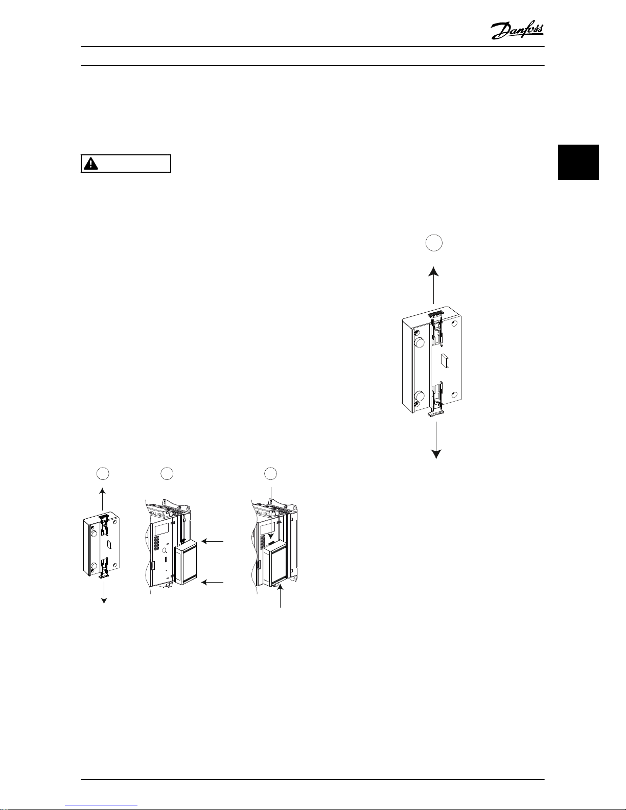
Installing the EtherNet/IP option:
1. Remove control power and mains supply from
the soft starter.
2. Fully pull out the top and bottom retaining clips
on the module (A).
3. Line up the module with the communication port
slot (B).
4. Push in the top and bottom retaining clips to
secure the module to the soft starter (C).
5. Connect Ethernet port 1 or port 2 on the module
to the network.
6. Apply control power to the soft starter.
177HA528.13
A
B
C
Illustration 3.1 Installing the EtherNet/IP Option
Remove the module from the soft starter:
1. Remove control power and mains supply from
the soft starter.
2. Disconnect all external wiring from the module.
3. Fully pull out the top and bottom retaining clips
on the module (A).
4. Pull the module away from the soft starter.
177HA378.12
A
Illustration 3.2 Removing the EtherNet/IP Option
Installation Installation Guide
MG17Q102 Danfoss A/S © 05/2017 All rights reserved. 7
3 3
Page 10

4 Connection
4.1 Soft Starter Connection
The EtherNet/IP Module is powered from the soft starter.
VLT® Compact Starter MCD 201/MCD 202
For the EtherNet/IP Module to accept eldbus commands, t a link across terminals A1–N2 on the soft starter.
VLT® Soft Starter MCD 500
If the MCD 500 has to be operated in remote mode, input links are required across terminals 17 and 25 to terminal 18. In
hand-on mode, links are not required.
NOTICE
FOR MCD 500 ONLY
Control via the eldbus communication network is always enabled in local control mode and can be enabled or
disabled in remote control mode (parameter 3-2 Comms in Remote). See the VLT® Soft Starter MCD 500 Operating Guide
for parameter details.
EtherNet/IP Module Connections
MCD 201/202 MCD 500
N2
177HA620.12
1
2
3
A1
17
18
25
177HA621.11
1
2
3
1 A1, N2: Stop input 1 (Auto-on mode)
17, 18: Stop input
25, 18: Reset input
2 EtherNet/IP Module 2 EtherNet/IP Module
3 RJ45 Ethernet ports 3 RJ45 Ethernet ports
Table 4.1 Connection Diagrams
Connection EtherNet/IP Module
8 Danfoss A/S © 05/2017 All rights reserved. MG17Q102
44
Page 11

4.2 Network Connection
4.2.1 Ethernet Ports
The EtherNet/IP Module has 2 Ethernet ports. If only 1
connection is required, either port can be used.
4.2.2 Cables
Suitable cables for EtherNet/IP Module connection:
•
Category 5
•
Category 5e
•
Category 6
•
Category 6e
4.2.3 EMC Precautions
To minimize electromagnetic interference, Ethernet cables
should be separated from motor and mains cables by
200 mm (7.9 in).
The Ethernet cable must cross the motor and mains cables
at an angle of 90°.
1
2
≥ 200 mm
90°
177HA653.10
1 3-phase supply
2 Ethernet cable
Illustration 4.1 Correct Running of Ethernet Cables
4.2.4 Network Establishment
The controller must establish communication directly with
each device before the device can participate in the
network.
4.3 Addressing
Each device in a network is addressed using a MAC
address and an IP address and can be assigned a symbolic
name associated with the MAC address.
•
The factory default is a static IP address
(192.168.1.2). The module also supports BootP
and DHCP addressing.
•
The symbolic name is optional and must be
congured within the device.
•
The MAC address is xed within the device and is
printed on a label on the front of the module.
ProfiNet
MAC: 00-02-A2-25-DC-B3
1 2
TX/RX 2
TX/RX 1
Link 2
Link 1
Error
Status
Power
177HA622.10
Illustration 4.2 MAC ID Location
Connection Installation Guide
MG17Q102 Danfoss A/S © 05/2017 All rights reserved. 9
4 4
Page 12

5 Device Conguration
5.1 Conguration Overview
The EtherNet/IP Module is congured with a static IP
address as default. To avoid IP address conict and to
ensure successful employment, connect the module
directly to a PC or laptop to congure the IP address
before connecting to the network. To congure the IP
address, or to enable BootP or DHCP addressing, use the
on-board web server.
NOTICE
The error LED ashes whenever the device is receiving
power but is not connected to a network. The error LED
ashes throughout the conguration process.
5.2 On-board Web Server
Ethernet attributes can be congured directly in the
EtherNet/IP Module using the on-board web server.
NOTICE
The web server only accepts connections from within the
same subnet domain.
To congure the device using the on-board web server:
1. Attach the module to a soft starter.
2. Connect Ethernet port 1 or port 2 on the module
to the network.
3. Apply control power to the soft starter.
4. Start a browser on the PC and enter the device
address, followed by /ipcong. The default
address for a new EtherNet/IP Module is
192.168.1.2.
177HA640.11
Illustration 5.1 Entering Network Settings
5. Edit the settings as required.
6. Click Submit to save the new settings.
7. If prompted, enter username and password.
7a Username: danfoss
7b Password: danfoss
NOTICE
If an IP address is changed and its record is lost, use the
Ethernet Device Conguration Tool to scan the network
and identify the module.
NOTICE
If changing the subnet mask, the server is unable to
communicate with the module after the new settings are
saved.
5.3 Ethernet Device Conguration Tool
If the IP address is unknown, or if the subnet mask of the
web server does not match, use the Ethernet Device
Conguration Tool to connect to the EtherNet/IP Module.
Changes made via the Ethernet Device Conguration Tool
cannot be stored permanently in the module and are lost
when control power is cycled. Use the Ethernet Device
Conguration Tool to change the IP address settings
temporarily. After that, use the new address to connect to
the module using the on-board web server to save the
settings permanently.
Download the Ethernet Device
Conguration Tool. To
install the software, administrator privileges are required
on the PC.
Downloading the tool:
1. Go to drives.danfoss.com/downloads/pc-tools/ to
nd the tool.
2. Make sure to have administrator privileges on the
PC before starting the installation.
3. Accept the End-User License Agreement.
4. Click Yes on the User account control dialog box.
NOTICE
If the PC has a rewall enabled, add the tool to the list
of authorized programs.
Device Conguration EtherNet/IP Module
10 Danfoss A/S © 05/2017 All rights reserved. MG17Q102
55
Page 13

Conguring the device using the Ethernet Device
Conguration Tool:
1. Attach the module to a soft starter.
2. Connect Ethernet port 1 or port 2 on the module
to the network.
3. Apply control power to the soft starter.
4. Start the Ethernet Device Conguration Tool.
177HA623.10
Illustration 5.2 Starting the Tool
5. Click Search Devices.
5a The software searches for connected
devices.
177HA641.10
Illustration 5.3 The Tool Shows the Connected Devices
6. To set a static IP address, click Congure and
select Set IP address.
177HA642.10
Illustration 5.4 Setting a Static IP Address
Device Conguration Installation Guide
MG17Q102 Danfoss A/S © 05/2017 All rights reserved. 11
5 5
Page 14

6 Operation
The EtherNet/IP Module is conformance tested to ODVA. For successful operation, the scanner must also support all
functions and interfaces described in this manual.
6.1 Device Conguration
The EtherNet/IP Module is an Adapter class device and must be managed by a Scanner class device over Ethernet.
6.2 Scanner Conguration
6.2.1 EDS File
Download the EDS le from drives.danfoss.com/services/pc-tools. The EDS le contains all required attributes of the
EtherNet/IP Module.
Once the EDS le is loaded, the individual EtherNet/IP Module must be dened.
6.3 LEDs
LED name LED status Description
1 2
TX/RX 2
TX/RX 1
Link 2
Link 1
Error
Status
Power
177HA627.10
Power
O The module is not powered up.
On The module receives power.
Error
O The module is not powered up or does not have an IP address.
Flashing Connection timeout.
On Duplicate IP address.
Status
O The module is not powered up or does not have an IP address.
Flashing The module has obtained an IP address but has not established any network
connections.
On Communication has been established.
Link x
O No network connection.
On Connected to a network.
TX/RX x Flashing Transmitting or receiving data.
Table 6.1 Feedback LEDs
Operation EtherNet/IP Module
12 Danfoss A/S © 05/2017 All rights reserved. MG17Q102
6
Page 15

7 Packet Structures
7.1 Ensuring Safe and Successful Control
Data written to the EtherNet/IP Module remains in its
register until the data is overwritten or the module is
reinitialized. The EtherNet/IP Module does not transfer
successive duplicate commands to the soft starter.
•
If the soft starter is started via
eldbus communication but stopped via the LCP or a remote input,
an identical start command cannot be used to
restart the soft starter.
•
If the soft starter is controlled via the LCP or the
remote inputs (and via eldbus communications),
a control command should be immediately
followed by a status query to conrm that the
command has been actioned.
NOTICE
Functions available only in VLT® Soft Starter MCD 500:
•
Parameter management
•
Dual motor control
•
Digital inputs
•
Jog
•
Current measurement in amperes
•
Power information
•
Warnings
NOTICE
VLT® Compact Starter MCD 201 open-loop soft starters
do not support motor current and motor temperature
information.
7.2 Cyclic Operation
This section lists requirements related to cyclic services for
the EtherNet/IP Module. The EtherNet/IP Module uses both
implicit (I/O) and explicit messaging, with a cyclic trigger
(minimum cyclic interval = 1 ms).
7.2.1 Assembly Objects
The EtherNet/IP Module supports the assembly objects
listed in Table 7.1.
Assembly instances Description Maximum size Type
104
Originator⇒target
2 (4) bytes Integer
154
Target⇒originator
6 (12) bytes Integer
Table 7.1 Assembly Objects
7.2.2 Control Commands
7.2.2.1 Receiving Control Data from the
Controller
The EtherNet/IP Module uses output assembly instance
104d in assembly class 0x04 to receive control data from
the controller. This instance is the only valid assembly
instance.
Byte
Function
1)
Details
0 Control word See chapter 7.2.2.2 Control Word (Write-only)
for details.
1
2 Reserved Must be 0.
3
Table 7.2 Valid Assembly Instance
1) All elds are in little- endian format.
7.2.2.2 Control Word (Write-only)
Use the structure in Table 7.3 to send a control command
to the soft starter.
Byte Bit Function
0
0–5 Reser ved Must be 0.
6 Run 0 = Stop command
1 = Start command
7 Reset Changing this bit from 0 to 1 resets a
trip.
1
0–4 Reser ved Must be 0.
5 Motor set
select
0 = Use primary motor set when
starting
1)
1 = Use secondary motor set when
starting
1)
6–7 Reser ved Must be 0.
Table 7.3 Control Word Structure
1) Ensure that the programmable input is not set to motor set select
before using this function.
Packet Structures Installation Guide
MG17Q102 Danfoss A/S © 05/2017 All rights reserved. 13
7 7
Page 16

7.2.2.3 Command Examples
Byte Value Description
Command: Start a soft starter
0
•
0b11000000 (0XC0)
or
•
0b01000000 (0X40)
0bX1000000, where X is 0 or 1 in the reset eld.
Command: Select primary or secondary motor settings
1
•
0b00000000 (0X0)
or
•
0b00100000 (0X20)
Select primary motor settings.
Select secondary motor settings.
Command: Reset a soft starter
0
•
0b11000000 (0XC0)
or
•
0b10000000 (0X80)
The reset only occurs when the previous reset bit is 0, otherwise the value of 1 is ignored.
Command: Stop a soft starter
0 0bX0000000
Table 7.4 Control Commands
7.2.3 Status Information
7.2.3.1 Reading Status Information from the Soft Starter
The EtherNet/IP Module uses input assembly instance 154d in assembly class 0X04 to send status information to the
controller. This instance is the only valid assembly instance.
Byte Function Details
0
Status word
See chapter 7.2.3.2 Status Word (Read-only) for details.
1
2
Reserved
Must be 0.
3
4
Motor current
Measured current is represented as a 32-bit value to 2 decimal places:
0000001 hex = 0.01 A
0000064 hex = 1.00 A
0010D47 hex = 689.35 A
5
6
7
8
Trip code
See chapter 7.2.3.3 Trip Codes.
9
10
Reserved
Must be 0.
11
Table 7.5 Status Information
Packet Structures EtherNet/IP Module
14 Danfoss A/S © 05/2017 All rights reserved. MG17Q102
77
Page 17

7.2.3.2 Status Word (Read-only)
Use the structure in Table 7.6 to query the status of the soft starter.
Bit Function Details MCD 201 MCD 202 MCD 500
0 Ready 0 = Start or stop command not acceptable
1 = Start or stop command acceptable
✓ ✓ ✓
1 Control from net 0 = Program mode
1 = Control from net
✓
2 Coasting 0 = Coasting
1 = Enabled
✓ ✓ ✓
3 Trip 0 = Not tripped
1 = Tripped
✓ ✓ ✓
4 Reserved Must be 0
5 Reserved Must be 0
6 Reserved Must be 0
7 Warning 0 = No warning
1 = Warning
✓
8 Ramping 0 = Not at full voltage (non-bypassed)
1 = Running (full voltage at the motor)
✓ ✓ ✓
9 Local/remote 0 = Local control
1 = Remote control
✓
10 Reserved Must be 0
11 On 0 = Unknown, not ready, ready to start, or tripped
1 = Starting, running, stopping, or jogging
✓ ✓ ✓
12 Reserved Must be 0
13 Reserved Must be 0
14 Reserved Must be 0
15 Temperature limit 0 = Motor operating below normal operating temperature
1 = Motor operating above normal operating temperature
✓ ✓ ✓
Table 7.6 Status Commands
Packet Structures Installation Guide
MG17Q102 Danfoss A/S © 05/2017 All rights reserved. 15
7 7
Page 18

7.2.3.3 Trip Codes
The trip code is reported in bytes 2–3 and 17 of the status word.
Trip code Description MCD 201 MCD 202 MCD 500
0 No trip
✓ ✓ ✓
11 Input A trip
✓
20 Motor overload
✓ ✓
21 Heat sink overtemperature
✓
23 L1 phase loss
✓
24 L2 phase loss
✓
25 L3 phase loss
✓
26 Current imbalance
✓ ✓
28 Instantaneous overcurrent
✓
29 Undercurrent
✓
50 Power loss
✓ ✓ ✓
54 Phase sequence
✓ ✓
55 Frequency
✓ ✓ ✓
60 Unsupported option (function not available in inside delta)
✓
61 FLC too high
✓
62 Parameter out of range
✓
70 Miscellaneous, including:
Current read err Lx
ATTENTION! Remove mains volts
Motor connection Tx
Firing fail Px
VZC fail Px
Low control volts
✓
75 Motor thermistor
✓ ✓
101 Excess start time
✓ ✓
102 Motor connection
✓
103 Shorted SCR
✓
113 Starter communication (between module and soft starter)
✓ ✓ ✓
114 Network communication (between module and network)
✓ ✓ ✓
115 L1-T1 shorted
✓
116 L2-T2 shorted
✓
117 L3-T3 shorted
✓
118 Motor 2 overload
✓
119
1)
Time-overcurrent (bypass overload)
✓ ✓
121 Battery/clock
✓
122 Thermistor circuit
✓
Table 7.7 Trip Codes
1) For VLT® Soft Starter MCD 500, time-overcurrent protection is only available on internally bypassed models.
Packet Structures EtherNet/IP Module
16 Danfoss A/S © 05/2017 All rights reserved. MG17Q102
77
Page 19

7.3 Acyclic Operation
This section provides information on objects, instances,
and attributes for acyclic operation. It also lists the
requirements related to acyclic services for the EtherNet/IP
Module.
7.3.1 Class 0X01 Identity Object
The EtherNet/IP Module supports the attributes for identity
objects listed in Table 7.8.
Attribute Function Description
1 Vendor Supported
2 Device type The attribute value is 12d
3 Product code Supported
4 Revision: Major,
minor
Revision value set in the EDS le
5 Status Status of the netIC module
6 Serial number Serial number of the netIC
module
7 Product name Supported
Table 7.8 Identity Object Attributes
7.3.2 Vendor-specic Objects
The EtherNet/IP Module supports vendor-specic class
objects 100, 101, 103, and 104.
7.3.2.1 Class 100 Objects (Read/Write)
Object name Class Instance Attribute
Motor full load current 100 101 100
Locked rotor time 100 102 100
Start mode 100 103 100
Current limit 100 104 100
Initial current 100 105 100
Start ramp time 100 106 100
Kickstart level 100 107 100
Kickstart time 100 108 100
Excess start time 100 109 100
Stop mode 100 110 100
Stop time 100 111 100
Adaptive control gain 100 112 100
Adaptive start prole 100 113 100
Adaptive stop prole 100 114 100
Brake torque 100 115 100
Brake time 100 116 100
Phase sequence 100 117 100
Current imbalance 100 118 100
Current imbalance delay 100 119 100
Undercurrent 100 120 100
Undercurrent delay 100 121 100
Object name Class Instance Attribute
Instantaneous overcurrent 100 122 100
Instantaneous overcurrent delay 100 123 100
Frequency check 100 124 100
Frequency variation 100 125 100
Frequency delay 100 126 100
Restart delay 100 127 100
Motor temperature check 100 128 100
Local/remote 100 129 100
Comms in remote 100 130 100
Input A function 100 131 100
Input A name 100 132 100
Input A trip 100 133 100
Input A trip delay 100 134 100
Input A initial delay 100 135 100
Remote reset logic 100 136 100
Relay A function 100 137 100
Relay A on delay 100 138 100
Relay A o delay 100 139 100
Relay B function 100 140 100
Relay B on delay 100 141 100
Relay B o delay 100 142 100
Relay C function 100 143 100
Relay C on delay 100 144 100
Relay C o delay 100 145 100
Low current ag 100 146 100
High current ag 100 147 100
Motor temperature ag 100 148 100
Analog output A 100 149 100
Analog A scale 100 150 100
Analog A maximum adjustment 100 151 100
Analog A minimum adjustment 100 152 100
Auto-start type 100 153 100
Auto-start time 100 154 100
Auto-stop type 100 155 100
Auto-stop time 100 156 100
Auto-reset action 100 157 100
Maximum resets 100 158 100
Reset delay groups A&B 100 159 100
Reset delay group C 100 160 100
Motor FLC-2 100 161 100
Locked rotor time-2 100 162 100
Start mode-2 100 163 100
Current limit-2 100 164 100
Initial current-2 100 165 100
Start ramp-2 100 166 100
Kickstart level-2 100 167 100
Kickstart time-2 100 168 100
Excess start time-2 100 169 100
Stop mode-2 100 170 100
Stop time-2 100 171 100
Adaptive control gain-2 100 172 100
Adaptive start prole-2 100 173 100
Adaptive stop prole-2 100 174 100
Packet Structures Installation Guide
MG17Q102 Danfoss A/S © 05/2017 All rights reserved. 17
7 7
Page 20

Object name Class Instance Attribute
Brake torque-2 100 175 100
Brake time-2 100 176 100
Language 100 177 100
User screen - top left 100 178 100
User screen - top right 100 179 100
User screen - bottom left 100 180 100
User screen - bottom right 100 181 100
Graph timebase 100 182 100
Graph maximum adjustment 100 183 100
Graph minimum adjustment 100 184 100
Mains reference voltage 100 185 100
Access code 100 186 100
Adjustment lock 100 187 100
Emergency run 100 188 100
Current calibration 100 189 100
Main contactor time 100 190 100
Bypass contactor time 100 191 100
Motor connection 100 192 100
Jog torque 100 193 100
Motor overload 100 194 100
Current imbalance 100 195 100
Undercurrent 100 196 100
Instantaneous overcurrent 100 197 100
Frequency 100 198 100
Heat sink overtemperature 100 199 100
Table 7.9 Class 100 Objects
7.3.2.2 Class 101 Objects (Read/Write)
Object name Class Instance Attribute
Excess start time 101 100 100
Input A trip 101 101 100
Motor thermistor 101 102 100
Starter communication 101 103 100
Network communication 101 104 100
Battery/clock 101 105 100
Low control volts 101 106 100
Comms timeout 101 107 100
Tracking gain 101 108 100
Tracking gain-2 101 109 100
Frequency detect 101 110 100
Bypass protection 101 111 100
Pedestal detect 101 112 100
Table 7.10 Class 101 Objects
7.3.2.3 Class 103 Objects (Read-only)
Object name Class Instance Attribute
Binary protocol version 103 100 100
Product type code 103 101 100
Minor software version 103 102 100
Major software version 103 103 100
Soft starter model 103 104 100
Parameter changed 103 105 100
Num parameter 103 106 100
Parameter value 103 107 100
Access type 103 108 100
Starter state 103 109 100
Warning 103 110 100
Initialized 103 111 100
Reserved 103 112 100
Parameters have changed 103 113 100
Phase sequence 103 114 100
Trip/warning code 103 115 100
Current 103 116 100
Current % of FLC 103 117 100
Motor 1 temperature 103 118 100
Motor 2 temperature 103 119 100
Power ( W) 103 120 100
Power scale 103 121 100
% power factor 103 122 100
Voltage (refers to mains reference
voltage)
103 123 100
Phase 1 current 103 124 100
Phase 2 current 103 125 100
Phase 3 current 103 126 100
Phase 1 voltage (refers to mains
reference voltage)
103 127 100
Phase 2 voltage (refers to mains
reference voltage)
103 128 100
Phase 3 voltage (refers to mains
reference voltage)
103 129 100
Minor revision 103 130 100
Major revision 103 131 100
Table 7.11 Class 103 Objects
Packet Structures EtherNet/IP Module
18 Danfoss A/S © 05/2017 All rights reserved. MG17Q102
77
Page 21

7.3.2.4 Class 104 Objects (Read-only)
Object name Class Instance Attribute
Major software version 104 101 100
Minor software version 104 102 100
Major software version 104 103 100
Minor software version 104 104 100
Major software version 104 105 100
Minor software version 104 106 100
Major software version 104 107 100
Minor software version 104 108 100
Model 104 109 100
Control variant 104 110 100
Backplane variant 104 111 100
Actual motor current 104 112 100
Variant high byte 104 113 100
Customer 104 114 100
Table 7.12 Class 104 Objects
7.3.3 Supported Services for Vendorspecic Objects
This section describes the operational instructions to carry
out acyclic services on class objects 100, 101, 103, and 104.
The EtherNet/IP Module supports the services for vendor-
specic objects in Table 7.13.
Service code Function Description
0x01 Get attribute all Only supported for class 0x01
identity object
0x10 Set attribute single Supported
0x0E Get attribute single Supported
Table 7.13 Supported Services
7.3.3.1 Set Attribute Single
To set an attribute, use the service code 0x10 (set attribute
single). For details on returned status codes, see
chapter 7.3.3.3 Status Codes for Acyclic Services.
Illustration 7.1 shows the successful writing of parameter
1-01 Motor Full Load Current (Class 100, Instance 101).
NOTICE
Class and service codes are written in hexadecimal
values, while instance is in decimal values.
177HA681.11
Illustration 7.1 Example: Setting the Value of Class 0x64
Instance 101 - Successful
Writing to a parameter that does not exist (or is read-only)
results in an error.
Illustration 7.2 shows the example of an attempt to write to
a non-existing parameter (Class 101, Instance 113).
177HA682.11
Illustration 7.2 Example: Setting the Value of Class 0x65
Instance 113 - Error
Packet Structures Installation Guide
MG17Q102 Danfoss A/S © 05/2017 All rights reserved. 19
7 7
Page 22

7.3.3.2 Get Attribute Single
To get an attribute, use the service code 0x0E (get
attribute single). For details on returned status codes, see
chapter 7.3.3.3 Status Codes for Acyclic Services.
Illustration 7.3 shows the successful reading of parameter
1-09 Excess Start Time (Class 100, Instance 109).
NOTICE
Class and service codes are written in hexadecimal
values, while instance is in decimal values.
177HA679.11
Illustration 7.3 Example: Retrieving the Value of Class 0x64,
Instance 109 - Successful
Reading a parameter that does not exist results in an error.
Illustration 7.4 shows the example of an attempt to read a
non-existing parameter (Class 101, Instance 113).
177HA680.11
Illustration 7.4 Example: Retrieving the Value of Class 0x65,
Instance 113 - Error
Packet Structures EtherNet/IP Module
20 Danfoss A/S © 05/2017 All rights reserved. MG17Q102
77
Page 23

7.3.3.3 Status Codes for Acyclic Services
Status
code
Status name Comments
0x00 Success This code is returned after successful execution of the service, that is
•
When the register mapped for service Get attribute single is successfully read.
•
When the register mapped for service Set attribute single is successfully set.
0x03 Invalid parameter value –
0x05 Path destination unknown The mapped register does not exist.
0x08 Service not supported The requested service is not available for this Object class/instance.
0x09 Invalid attribute value This code only applies to the service Set attribute single. It is returned if the value is out of range
for the mapped register.
0x0E Attribute not settable This code only applies to the service Set attribute single. It is returned if the mapped register is
read-only.
0x14 Attribute not supported The attribute specied in the request is not supported.
0x16 Object does not exist The object specied does not exist in the device.
Table 7.14 Status Codes, Get/Set Attribute Single
Packet Structures Installation Guide
MG17Q102 Danfoss A/S © 05/2017 All rights reserved. 21
7 7
Page 24

8 Network Design
The EtherNet/IP Module supports star, line, and ring
topologies.
8.1 Star Topology
In a star network, all controllers and devices connect to a
central network switch.
177HA628.10
Illustration 8.1 Star Network Topology
8.2 Line Topology
In a line network, the controller connects directly to 1 port
of the
rst EtherNet/IP Module. The 2nd Ethernet port of
the EtherNet/IP Module connects to another module,
which in turn connects to another module until all devices
are connected.
177HA629.10
Illustration 8.2 Line Network Topology
NOTICE
The EtherNet/IP Module has an integrated switch to
allow data to pass through in line topology. The
EtherNet/IP Module must be receiving control power
from the soft starter for the switch to operate.
NOTICE
If the connection between 2 devices is interrupted, the
controller cannot communicate with devices after the
interruption point.
NOTICE
Each connection adds a delay to communication with the
next module. The maximum number of devices in a line
network is 32. Exceeding this number may reduce the
reliability of the network.
8.3 Ring Topology
In a ring topology network, the controller connects to the
1st EtherNet/IP Module via a network switch. The 2
nd
Ethernet port of the EtherNet/IP Module connects to
another module, which in turn connects to another
module until all devices are connected. The nal module
connects back to the switch.
The EtherNet/IP Module supports beacon-based ring node
conguration.
177HA630.10
Illustration 8.3 Ring Network Topology
NOTICE
The network switch must support loss of line detection.
Network Design EtherNet/IP Module
22 Danfoss A/S © 05/2017 All rights reserved. MG17Q102
88
Page 25

8.4 Combined Topologies
A single network can include both star and line
components.
177HA631.10
Illustration 8.4 Combined Star/Line Network Topology
Network Design Installation Guide
MG17Q102 Danfoss A/S © 05/2017 All rights reserved. 23
8 8
Page 26

9 Specications
Enclosure
Dimensions, W x H x D [mm (in)] 40 x 166 x 90 (1.6 x 6.5 x 3.5)
Weight 250 g (8.8 Oz)
Protection IP20
Mounting
Spring-action plastic mounting clips 2
Connections
Soft starter 6-way pin assembly
Contacts Gold ash
Networks RJ45
Settings
IP address BootP, automatically assigned, congurable
Device name Congurable
Network
Link speed 10 Mbps, 100 Mbps (auto-detect)
Full duplex
Auto crossover
Power
Consumption (steady state, maximum) 35 mA at 24 V DC
Reverse polarity protected
Galvanically isolated
Certication
RCM IEC 60947-4-2
CE IEC 60947-4-2
ODVA EtherNet/IP conformance tested
Environmental
Operating temperature -10 to +60 °C (14–140 °F), above 40 °C (104 °F) with derating
Storage temperature -25 to +60 °C (-13 to +140 °F)
Humidity 5–95% relative humidity
Pollution degree Pollution degree 3
Vibration IEC 60068-2-6
Specications EtherNet/IP Module
24 Danfoss A/S © 05/2017 All rights reserved. MG17Q102
99
Page 27

Index
A
Abbreviations........................................................................................... 4
Acyclic service........................................................................................ 17
Additional resources.............................................................................. 3
Approvals................................................................................................... 3
Assembly class................................................................................ 13, 14
Assembly instance............................................................................... 14
Assembly object.................................................................................... 13
Auto-on mode.......................................................................................... 5
B
Busbar......................................................................................................... 5
C
Cable
category................................................................................................. 9
Ethernet cable..................................................................................... 9
Capacitors
Power factor correction capacitor................................................ 5
Certications............................................................................................. 3
Class object............................................................................................. 17
Commands
Control.......................................................................................... 13, 14
Start................................................................................................ 13, 15
Status.................................................................................................... 15
Stop................................................................................................ 13, 15
Connections........................................................................................... 24
Contactors
Bypass contactor................................................................................ 5
Main contactor.................................................................................... 6
Control command......................................................................... 13, 14
Control word.......................................................................................... 13
Control word structure....................................................................... 13
Conventions.............................................................................................. 4
Cyclic service.......................................................................................... 13
D
Dimensions............................................................................................. 24
E
Electromagnetic interference............................................................. 9
Ethernet attribute................................................................................. 10
H
Heat sink..................................................................................................... 5
I
Identity object....................................................................................... 17
Inputs
Remote................................................................................................... 5
Installing EtherNet/IP option.............................................................. 7
Intended use............................................................................................. 3
IP address.............................................................................. 9, 10, 12, 24
IP address conict................................................................................. 10
L
LED
Description......................................................................................... 12
LED........................................................................................................... 4
Name.................................................................................................... 12
Status.................................................................................................... 12
M
MAC address............................................................................................. 9
Motor
connection............................................................................................ 6
N
Network
Auto crossover.................................................................................. 24
Full duplex.......................................................................................... 24
Line........................................................................................................ 22
Link speed........................................................................................... 24
Ring....................................................................................................... 22
Star........................................................................................................ 22
Q
Qualied personnel........................................................................... 3, 5
R
Removing EtherNet/IP Option........................................................... 7
Reset mode............................................................................................... 8
S
Start command............................................................................... 13, 15
Status command................................................................................... 15
Status word............................................................................................. 14
Stop command............................................................................... 13, 15
Subnet mask........................................................................................... 10
Supply..................................................................................................... 5, 6
Symbols...................................................................................................... 4
T
Terminals
A1............................................................................................................. 8
N2............................................................................................................. 8
Index Installation Guide
MG17Q102 Danfoss A/S © 05/2017 All rights reserved. 25
Page 28

U
Unintended start..................................................................................... 5
W
Weight...................................................................................................... 24
Index EtherNet/IP Module
26 Danfoss A/S © 05/2017 All rights reserved. MG17Q102
Page 29

Index Installation Guide
MG17Q102 Danfoss A/S © 05/2017 All rights reserved. 27
Page 30

Danfoss can accept no responsibility for possible errors in catalogues, brochures and other printed material. Danfoss reserves the right to alter its products without notice. This also applies to
products already on order provided that such alterations can be made without subsequential changes being necessary in specications already agreed. All trademarks in this material are property
of the respective companies. Danfoss and the Danfoss logotype are trademarks of Danfoss A/S. All rights reserved.
Danfoss A/S
Ulsnaes 1
DK-6300 Graasten
vlt-drives.danfoss.com
*MG17Q102*
175R1168 MG17Q102 05/2017
 Loading...