

Danfoss VLT Compact Starter MCD 201, VLT Compact Starter MCD 202, VLT Soft Starter MCD 500 Installation Manual
Page 1
ENGINEERING TOMORROW
Installation Guide
EtherNet/IP Module
VLT® Compact Starter MCD 201/MCD 202
VLT® Soft Starter MCD 500
vlt-drives.danfoss.com
Page 2

Page 3

Contents
1 Introduction
3
1.1 Purpose of the Manual
3
1.2 Additional Resources
3
1.3 Product Overview
3
1.4 Approvals and Certications
3
1.5 Disposal
3
1.6 Symbols, Abbreviations, and Conventions
4
2 Safety
5
2.1 Qualied Personnel
5
2.2 General Warnings
5
3 Installation
7
3.1 Installation Procedure
7
4 Connection
8
4.1 Soft Starter Connection
8
4.2 Network Connection
9
4.2.1 Ethernet Ports 9
4.2.2 Cables 9
4.2.3 EMC Precautions 9
4.2.4 Network Establishment 9
4.3 Addressing
9
5 Device Conguration
10
5.1 On-board Web Server
10
5.2 Ethernet Device Conguration Tool
10
6 Operation
12
6.1 Device Classication
12
6.2 Scanner Conguration
12
6.2.1 EDS File 12
6.3 LEDs
12
7 Packet Structures
13
7.1 Ensuring Safe and Successful Control
13
7.2 Control Commands (Write Only)
13
7.3 Status Commands (Read Only)
14
7.4 Soft Starter Internal Register Address
16
7.5 Parameter Management (Read/Write)
18
7.6 Trip Codes
18
Contents Installation Guide
MG17M202 Danfoss A/S © 05/2017 All rights reserved. 1
Page 4

7.6.1 Internal Fault X 19
8 Network Design
20
8.1 Star Topology
20
8.2 Line Topology
20
8.3 Ring Topology
20
8.4 Combined Topologies
21
9 Specications
22
Index
23
Contents EtherNet/IP Module
2 Danfoss A/S © 05/2017 All rights reserved. MG17M202
Page 5
1 Introduction
1.1 Purpose of the Manual
This installation guide provides information for the instal-
lation of the EtherNet/IP option module for VLT® Compact
Starter MCD 201/MCD 202 and VLT® Soft Starter MCD 500.
The installation guide is intended for use by qualied
personnel.
Users are assumed to be familiar with:
•
VLT® soft starters.
•
EtherNet/IP technology.
•
PC or PLC that is used as a master in the system.
Read the instructions before installation and ensure that
the instructions for safe installation are observed.
VLT® is a registered trademark.
EtherNet/IP™ is a trademark of ODVA, Inc.
1.2 Additional Resources
Resources available for the soft starter and optional
equipment:
•
The VLT® Compact Starter MCD 200 Operating
Instructions provide the necessary information for
getting the soft starter up and running.
•
The VLT® Soft Starter MCD 500 Operating Guide
provides the necessary information for getting
the soft starter up and running.
Supplementary publications and manuals are available
from Danfoss. See drives.danfoss.com/knowledge-center/
technical-documentation/ for listings.
1.3
Product Overview
1.3.1 Intended Use
This installation guide relates to EtherNet/IP Module for
VLT® soft starters.
The EtherNet/IP interface is designed to communicate with
any system complying with the CIP EtherNet/IP standard.
EtherNet/IP provides users with the network tools to
deploy standard Ethernet technology for manufacturing
applications while enabling internet and enterprise connectivity.
EtherNet/IP Module is intended for use with:
•
VLT® Compact Starter MCD 201/MCD 202,
24 V AC/V DC and 110/240 V AC control voltage.
•
VLT® Soft Starter MCD 500, all models.
NOTICE
The EtherNet/IP Module is NOT suitable for use with the
MCD 201/MCD 202 compact starters using 380/440 V AC
control voltage.
The EtherNet/IP Module allows a Danfoss soft starter to
connect to an Ethernet network and be controlled or
monitored using an Ethernet communication model.
Separate modules are available for PROFINET, Modbus TCP,
and EtherNet/IP networks.
The EtherNet/IP Module operates at the application layer.
Lower levels are transparent to the user.
Familiarity with Ethernet protocols and networks is
required to operate the EtherNet/IP Module successfully. If
there are
diculties when using this device with thirdparty products, including PLCs, scanners, and
commissioning tools, contact the relevant supplier.
1.4 Approvals and Certications
More approvals and certications are available. For more
information, contact a local Danfoss partner.
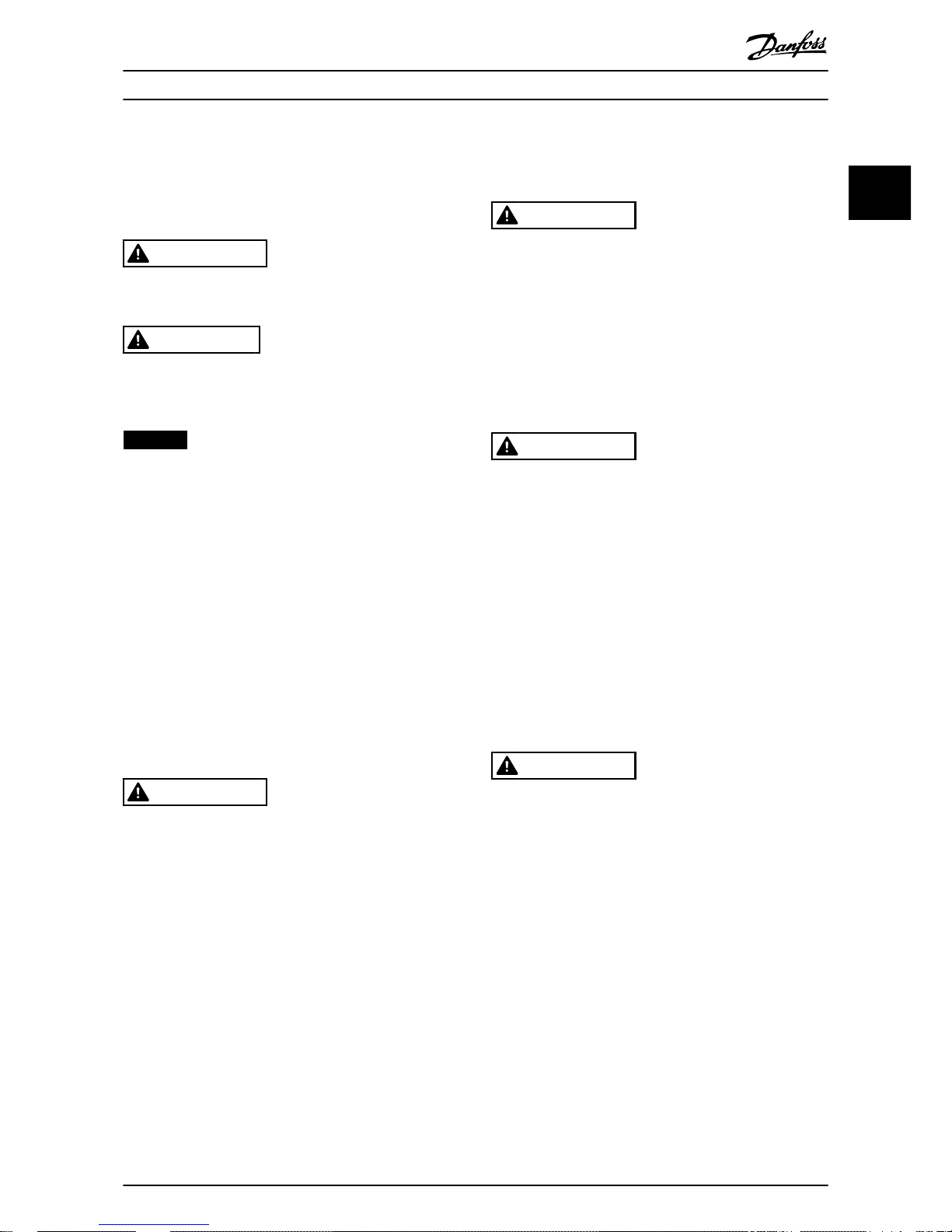
1.5
Disposal
Do not dispose of equipment containing
electrical components together with
domestic waste.
Collect it separately in accordance with
local and currently valid legislation.
Introduction Installation Guide
MG17M202 Danfoss A/S © 05/2017 All rights reserved. 3
1 1
Page 6

1.6 Symbols, Abbreviations, and
Conventions
Abbreviation Denition
CIP™
Common industrial protocol
DHCP Dynamic host conguration protocol
EMC Electromagnetic compatibility
IP Internet protocol
LCP Local control panel
LED Light-emitting diode
PC Personal computer
PLC Programmable logic controller
Table 1.1 Symbols and Abbreviations
Conventions
Numbered lists indicate procedures.
Bullet lists indicate other information and description of
illustrations.
Italicized text indicates:
•
Cross-reference.
•
Link.
•
Parameter name.
•
Parameter group name.
•
Parameter option.
Introduction EtherNet/IP Module
4 Danfoss A/S © 05/2017 All rights reserved. MG17M202
11
Page 7
2 Safety
The following symbols are used in this manual:
WARNING
Indicates a potentially hazardous situation that could
result in death or serious injury.
CAUTION
Indicates a potentially hazardous situation that could
result in minor or moderate injury. It can also be used to
alert against unsafe practices.
NOTICE
Indicates important information, including situations that
can result in damage to equipment or property.
2.1 Qualied Personnel
Correct and reliable transport, storage, installation,
operation, and maintenance are required for the troublefree and safe operation of the soft starter. Only qualied
personnel are allowed to install or operate this equipment.
Qualied personnel are dened as trained sta, who are
authorized to install, commission, and maintain equipment,
systems, and circuits in accordance with pertinent laws and
regulations. Also, the qualied personnel must be familiar
with the instructions and safety measures described in this
installation guide.
2.2
General Warnings
WARNING
ELECTRICAL SHOCK HAZARD
VLT® Soft Starter MCD 500 contains dangerous voltages
when connected to mains voltage. Only a qualied
electrician should carry out the electrical installation.
Improper installation of the motor or the soft starter can
cause death, serious injury, or equipment failure. Follow
the guidelines in this manual and local electrical safety
codes.
Models MCD5-0360C ~ MCD5-1600C:
Treat the busbar and heat sink as live parts whenever
the unit has mains voltage connected (including when
the soft starter is tripped or waiting for a command).
WARNING
PROPER GROUNDING
Disconnect the soft starter from mains voltage before
carrying out repair work.
It is the responsibility of the person installing the soft
starter to provide proper grounding and branch circuit
protection according to local electrical safety codes.
Do not connect power factor correction capacitors to the
output of the VLT® Soft Starter MCD 500. If static power
factor correction is employed, it must be connected to
the supply side of the soft starter.
WARNING
IMMEDIATE START
In auto-on mode, the motor can be controlled remotely
(via remote inputs) while the soft starter is connected to
mains.
MCD5-0021B ~ MCD5-961B:
Transportation, mechanical shock, or rough handling
may cause the bypass contactor to latch into the On
state.
To prevent the motor from starting immediately on rst
commissioning or operation after transportation:
•
Always ensure that the control supply is applied
before the power.
•
Applying control supply before power ensures
that the contactor state is initialized.
WARNING
UNINTENDED START
When the soft starter is connected to AC mains, DC
supply, or load sharing, the motor can start at any time.
Unintended start during programming, service, or repair
work can result in death, serious injury, or property
damage. The motor can start with an external switch, a
eldbus command, an input reference signal from the
LCP or LOP, via remote operation using MCT 10 Set-up
Software, or after a cleared fault condition.
To prevent unintended motor start:
•
Press [O/Reset] on the LCP before
programming parameters.
•
Disconnect the soft starter from the mains.
•
Completely wire and assemble the soft starter,
motor, and any driven equipment before
connecting the soft starter to AC mains, DC
supply, or load sharing.
Safety Installation Guide
MG17M202 Danfoss A/S © 05/2017 All rights reserved. 5
2 2
Page 8

WARNING
SAFETY OF PERSONNEL
The soft starter is not a safety device and does not
provide electrical isolation or disconnection from the
supply.
•
If isolation is required, the soft starter must be
installed with a main contactor.
•
Do not rely on the start and stop functions for
safety of personnel. Faults occurring in the
mains supply, the motor connection, or the
electronics of the soft starter can cause
unintended motor starts or stops.
•
If faults occur in the electronics of the soft
starter, a stopped motor may start. A temporary
fault in the supply mains or loss of motor
connection can also cause a stopped motor to
start.
To provide safety of personnel and equipment, control
the isolation device through an external safety system.
NOTICE
Before changing any parameter settings, save the current
parameter to a le using MCD PC Software or the Save
User Set function.
NOTICE
Use the autostart feature with caution. Read all the notes
related to autostart before operation.
The examples and diagrams in this manual are included
solely for illustrative purposes. The information contained
in this manual is subject to change at any time and
without prior notice. Responsibility or liability is never
accepted for direct, indirect, or consequential damage
resulting from the use or application of this equipment.
Safety EtherNet/IP Module
6 Danfoss A/S © 05/2017 All rights reserved. MG17M202
22
Page 9

3 Installation
3.1 Installation Procedure
CAUTION
EQUIPMENT DAMAGE
If mains and control voltage are applied when installing
or removing options/accessories, it may damage the
equipment.
To avoid damage:
•
Remove mains and control voltage from the
soft starter before attaching or removing
options/accessories.
Installing the EtherNet/IP option:
1. Remove control power and mains supply from
the soft starter.
2. Fully pull out the top and bottom retaining clips
on the module (A).
3. Line up the module with the communication port
slot (B).
4. Push in the top and bottom retaining clips to
secure the module to the soft starter (C).
5. Connect Ethernet port 1 or port 2 on the module
to the network.
6. Apply control power to the soft starter.
177HA528.13
A
B
C
Illustration 3.1 Installing the EtherNet/IP Option
Remove the module from the soft starter:
1. Remove control power and mains supply from
the soft starter.
2. Disconnect all external wiring from the module.
3. Fully pull out the top and bottom retaining clips
on the module (A).
4. Pull the module away from the soft starter.
177HA378.12
A
Illustration 3.2 Removing the EtherNet/IP Option
Installation Installation Guide
MG17M202 Danfoss A/S © 05/2017 All rights reserved. 7
3 3
Page 10

4 Connection
4.1 Soft Starter Connection
The EtherNet/IP Module is powered from the soft starter.
VLT® Compact Starter MCD 201/MCD 202
For the EtherNet/IP Module to accept eldbus commands,
t a link across terminals A1–N2 on the soft starter.
VLT® Soft Starter MCD 500
If the MCD 500 has to be operated in remote mode, input
links are required across terminals 17 and 25 to terminal
18. In hand-on mode, links are not required.
NOTICE
FOR MCD 500 ONLY
Control via the eldbus communication network is
always enabled in local control mode and can be
enabled or disabled in remote control mode (parameter
3-2 Comms in Remote). See the VLT® Soft Starter MCD 500
Operating Guide for parameter details.
EtherNet/IP Module Connections
MCD 201/202 MCD 500
N2
177HA620.12
1
2
3
A1
17
18
25
177HA621.11
1
2
3
1 A1, N2: Stop input 1 (Auto-on mode)
17, 18: Stop input
25, 18: Reset input
2 EtherNet/IP Module 2 EtherNet/IP Module
3 RJ45 Ethernet ports 3 RJ45 Ethernet ports
Table 4.1 Connection Diagrams
Connection EtherNet/IP Module
8 Danfoss A/S © 05/2017 All rights reserved. MG17M202
44
Page 11

4.2 Network Connection
4.2.1 Ethernet Ports
The EtherNet/IP Module has 2 Ethernet ports. If only 1
connection is required, either port can be used.
4.2.2 Cables
Suitable cables for EtherNet/IP Module connection:
•
Category 5
•
Category 5e
•
Category 6
•
Category 6e
4.2.3 EMC Precautions
To minimize electromagnetic interference, Ethernet cables
should be separated from motor and mains cables by
200 mm (7.9 in).
The Ethernet cable must cross the motor and mains cables
at an angle of 90°.
1
2
≥ 200 mm
90°
177HA653.10
1 3-phase supply
2 Ethernet cable
Illustration 4.1 Correct Running of Ethernet Cables
4.2.4 Network Establishment
The controller must establish communication directly with
each device before the device can participate in the
network.
4.3 Addressing
Each device in a network is addressed using a MAC
address and an IP address and can be assigned a symbolic
name associated with the MAC address.
•
The module receives a dynamic IP address when
it is connected to the network or can be assigned
a static IP address during conguration.
•
The symbolic name is optional and must be
congured within the device.
•
The MAC address is xed within the device and is
printed on a label on the front of the module.
ProfiNet
MAC: 00-02-A2-25-DC-B3
1 2
TX/RX 2
TX/RX 1
Link 2
Link 1
Error
Status
Power
177HA622.10
Illustration 4.2 MAC ID Location
Connection Installation Guide
MG17M202 Danfoss A/S © 05/2017 All rights reserved. 9
4 4
Page 12

5 Device Conguration
5.1 On-board Web Server
Ethernet attributes can be congured directly in the
EtherNet/IP Module using the on-board web server.
NOTICE
The Error LED ashes whenever the module receives
power but is not connected to a network. The Error LED
ashes throughout the conguration process.
NOTICE
The default address for a new EtherNet/IP Module is
192.168.0.2. The default subnet mask is 255.255.255.0.
The web server only accepts connections from within the
same subnet domain. Use the Ethernet Device Congu-
ration Tool to temporarily change the network address of
the module to match the network address of the PC
running the tool, if required.
To congure the device using the on-board web server:
1. Attach the module to a soft starter.
2. Connect Ethernet port 1 or port 2 on the module
to the network.
3. Apply control power to the soft starter.
4. Start a browser on the PC and enter the device
address, followed by /ipcong. The default
address for a new EtherNet/IP Module is
192.168.0.2.
177ha690.10
Illustration 5.1 Entering Network Settings
5. Edit the settings as required.
6. Click Submit to save the new settings.
6a To store the settings permanently in the
module, tick Set permanently.
7. If prompted, enter username and password.
7a Username: danfoss
7b Password: danfoss
NOTICE
If an IP address is changed and its record is lost, use the
Ethernet Device Conguration Tool to scan the network
and identify the module.
NOTICE
If changing the subnet mask, the server is unable to
communicate with the module after the new settings are
saved.
5.2 Ethernet Device Conguration Tool
Download the Ethernet Device Conguration Tool from
www.danfoss.com/drives.
Changes made via the Ethernet Device Conguration Tool
cannot be stored permanently in the EtherNet/IP Module.
To congure attributes permanently in the EtherNet/IP
Module, use the on-board web server.
Conguring the device using the Ethernet Device
Conguration Tool:
1. Attach the module to a soft starter.
2. Connect Ethernet port 1 or port 2 on the module
to the Ethernet port of the PC.
3. Apply control power to the soft starter.
4. Start the Ethernet Device Conguration Tool.
Device Conguration EtherNet/IP Module
10 Danfoss A/S © 05/2017 All rights reserved. MG17M202
55
Page 13

177HA623.10
Illustration 5.2 Starting the Tool
5. Click Search Devices.
5a The software searches for connected
devices.
177HA641.10
Illustration 5.3 The Tool Shows the Connected Devices
6. To set a static IP address, click
Congure and
select Set IP address.
177HA642.10
Illustration 5.4 Setting a Static IP Address
Device Conguration Installation Guide
MG17M202 Danfoss A/S © 05/2017 All rights reserved. 11
5 5
Page 14

6 Operation
The EtherNet/IP Module is designed for use in a system
complying with the ODVA Common Industrial Protocol. For
successful operation, the scanner must also support all
functions and interfaces described in this manual.
6.1 Device Classication
The EtherNet/IP Module is an Adapter class device and
must be managed by a Scanner class device over Ethernet.
6.2 Scanner Conguration
6.2.1 EDS File
Download the EDS le from drives.danfoss.com/services/pc-
tools. The EDS le contains all required attributes of the
EtherNet/IP Module.
Once the EDS le is loaded, dene the individual
EtherNet/IP Module. Input/output registers must be 240
bytes in size and type INT.
177HA660.10
Illustration 6.1 Module Denition of the EtherNet/IP Module,
Using RSLogix 5000
6.3 LEDs
LED name LED status Description
1 2
TX/RX 2
TX/RX 1
Link 2
Link 1
Error
Status
Power
177HA627.10
Power
O The module is not powered up.
On The module receives power.
Error
O The module is not powered up or does not have an IP address.
Flashing Connection timeout.
On Duplicate IP address.
Status
O The module is not powered up or does not have an IP address.
Flashing The module has obtained an IP address but has not established any network
connections.
On Communication has been established.
Link x
O No network connection.
On Connected to a network.
TX/RX x Flashing Transmitting or receiving data.
Table 6.1 Feedback LEDs
Operation EtherNet/IP Module
12 Danfoss A/S © 05/2017 All rights reserved. MG17M202
6
Page 15

7 Packet Structures
NOTICE
All references to registers refer to the registers within the
module unless otherwise stated.
NOTICE
Some soft starters do not support all functions.
7.1 Ensuring Safe and Successful Control
Data written to the Ethernet Module remains in its
registers until the data is overwritten or the module is
reinitialized. The Ethernet Module does not transfer
successive duplicate commands to the soft starter.
NOTICE
If the soft starter is started via eldbus communications
but stopped via the LCP or a remote input, an identical
start command cannot be used to restart the soft starter.
To operate safely and successfully in an environment
where the soft starter may also be controlled via the LCP
or the remote inputs (and eldbus communications), a
control command should be immediately followed by a
status query to conrm that the command has been
actioned.
7.2 Control Commands (Write Only)
NOTICE
To operate reliably, only 1 bit in byte 0 may be set at a time. Set all other bits to 0.
Byte Bit Function
0
0
0 = Stop command.
1 = Start command.
1
0 = Enable start or stop command.
1 = Quick stop (coast to stop) and disable start command.
2
0 = Enable start or stop command.
1 = Reset command and disable start command.
3–7 Reserved.
1
0–1
0 = Use soft starter remote input to select motor set.
1 = Use primary motor when starting.
1)
2 = Use secondary motor when starting.
1)
3 = Reserved.
2–7 Reserved.
Table 7.1 Structures Used for Sending Control Commands to the Soft Starter
1) Ensure that the programmable input is not set to Motor set select before using this function.
Packet Structures Installation Guide
MG17M202 Danfoss A/S © 05/2017 All rights reserved. 13
7 7
Page 16

7.3 Status Commands (Read Only)
NOTICE
Some soft starters do not support all functions.
Byte Bit Function Details
0
0 Trip 1 = Tripped.
1 Warning 1 = Warning.
2 Running
0 = Unknown, not ready, ready to start, or tripped.
1 = Starting, running, stopping, or jogging.
3 Reserved –
4 Ready
0 = Start or stop command not acceptable.
1 = Start or stop command acceptable.
5 Control from net 1 = Always, except in program mode.
6 Local/Remote
0 = Local control.
1 = Remote control.
7 At reference 1 = Running (full voltage at the motor).
1 0–7 Status
0 = Unknown (menu open).
2 = Soft starter not ready (restart delay or thermal delay).
3 = Ready to start (including warning state).
4 = Starting or running.
5 = Soft stopping.
7 = Trip.
8 = Jog forward.
9 = Jog reverse.
2–3 0–15 Trip/warning code See trip codes in Table 7.4.
4
1)
0–7 Motor current (low byte)
Current (A).
5
1)
0–7 Motor current (high byte)
6 0–7 Motor 1 temperature Motor 1 thermal model (%).
7 0–7 Motor 2 temperature Motor 2 thermal model (%).
8–9
0–5 Reserved –
6–8 Product parameter list version –
9–15
Product type code
2)
–
10 0–7 Reserved –
11 0–7 Reserved –
12
3)
0–7 Changed parameter number
0 = No parameters have changed.
1~255 = Index number of the last parameter changed.
13 0–7 Parameters Total numbers of parameters available in the soft starter.
14–15
0–13
Changed parameter value
3)
Value of the last parameter that was changed, as indicated in byte 12.
14–15 Reserved –
Packet Structures EtherNet/IP Module
14 Danfoss A/S © 05/2017 All rights reserved. MG17M202
77
Page 17

Byte Bit Function Details
16
0–4 Soft starter state
0 = Reserved.
1 = Ready.
2 = Starting.
3 = Running.
4 = Stopping.
5 = Not ready (restart delay, restart temperature check).
6 = Tripped.
7 = Programming mode.
8 = Jog forward.
9 = Jog reverse.
5 Warning 1 = Warning.
6 Initialized
0 = Uninitialized.
1 = Initialized.
7 Local control
0 = Local control.
1 = Remote control.
17
0 Parameters
0 = Parameters have changed since last parameter read.
1 = No parameters have changed.
1 Phase sequence
0 = Negative phase sequence.
1 = Positive phase sequence.
2–7
Trip code
4)
See trip codes in Table 7.4.
18–19
0–13 Current Average rms current across all 3 phases.
14–15 Reserved –
20–21
0–13 Current (% motor FLC) –
14–15 Reserved –
22 0–7 Motor 1 thermal model (%) –
23 0–7 Motor 2 thermal model (%) –
24–25
5)
0–11 Power –
12–13 Power scale –
14–15 Reserved –
26 0–7 % power factor 100% = power factor of 1.
27 0–7 Reserved –
28 0–7 Reserved –
29 0–7 Reserved –
30–31
0–13 Phase 1 current (rms) –
14–15 Reserved –
32–33
0–13 Phase 2 current (rms) –
14–15 Reserved –
34–35
0–13 Phase 3 current (rms) –
14–15 Reserved –
36 0–7 Reserved –
37 0–7 Reserved –
38 0–7 Reserved –
39 0–7 Reserved –
40 0–7 Reserved –
41 0–7 Reserved –
42 0–7 Parameter list minor revision –
43 0–7 Parameter list major revision –
44
0–3 Digital input state For all inputs, 0 = open, 1 = closed.
0 = Start.
1 = Stop.
2 = Reset.
3 = Input A
4–7 Reserved –
Packet Structures Installation Guide
MG17M202 Danfoss A/S © 05/2017 All rights reserved. 15
7 7
Page 18

Byte Bit Function Details
45 0–7 Reserved –
Table 7.2 Structures Used for Querying the Status of the Soft Starter
1) For models MCD5-0053B and smaller, this value is 10 times greater than the value shown on the LCP.
2) Product type code: 4=MCD 200, 5=MCD 500.
3) Reading bytes 14–15 (changed parameter value) reset byte 12 (changed parameter number) and bit 0 of byte 17 (parameters have changed).
Always read bytes 12 and 17 before reading bytes 14–15.
4) Bits 2–7 of byte 17 report the soft starter ’s trip or warning code. If the value of bits 0–4 of byte 16 is 6, the soft starter has tripped. If bit 5=1, a
warning has activated and the soft starter continues operation.
5) Powerscale functions as follows:
0 = Multiply power by 10 to get W.
1 = Multiply power by 100 to get W.
2 = Power is shown in kW.
3 = Multiply power by 10 to get kW.
7.4 Soft Starter Internal Register Address
Internal registers within the soft starter have the functions listed in Table 7.3. These registers are not directly accessible via
eldbus.
Register Description Bits Details
0 Version
0–5 Binary protocol version number.
6–8 Product parameter list version.
9–15
Product type code.
1)
1 Device details – –
2
2)
Changed parameter number
0–7
0 = No parameters have changed.
1~255 = Index number of the last parameter changed.
8–15 Total number of parameters available in the soft starter.
3
2)
Changed parameter value
0–13 Value of the last parameter that was changed, as indicated in register 2.
14–15 Reserved.
4 Soft starter state
0–4
0 = Reserved.
1 = Ready.
2 = Starting.
3 = Running.
4 = Stopping.
5 = Not ready (restart delay, restart temperature check).
6 = Tripped.
7 = Programming mode.
8 = Jog forward.
9 = Jog reverse.
5 1 = Warning.
6
0 = Warning.
1 = Initialized.
7
0 = Local control.
1 = Remote control.
8
0 = Parameters have changed.
1 = No parameters have changed.
2)
9
0 = Negative phase sequence.
1 = Positive phase sequence.
10–15
See trip codes in Table 7.4.
3)
5 Current
0–13
Average rms current across all 3 phases.
4)
14–15 Reserved.
6 Current
0–9 Current (% motor FLC).
10–15 Reserved.
Packet Structures EtherNet/IP Module
16 Danfoss A/S © 05/2017 All rights reserved. MG17M202
77
Page 19

Register Description Bits Details
7 Motor temperature
0–7 Motor 1 thermal model (%).
8–15 Motor 2 thermal model (%).
8
5)
Power
0–11 Power.
12–13 Power scale.
14–15 Reserved.
9 % Power factor
0–7 100% = power factor of 1.
8–15 Reserved.
10 Reserved 0–15 –
11
4)
Current
0–13 Phase 1 current (rms).
14–15 Reserved.
12
4)
Current
0–13 Phase 2 current (rms).
14–15 Reserved.
13
4)
Current
0–13 Phase 3 current (rms).
14–15 Reserved.
14 Reserved – –
15 Reserved – –
16 Reserved – –
17 Parameter list version number
0–7 Parameter list minor revision.
8–15 Parameter list major revision.
18 Digital input state
0–15
For all inputs, 0 = open, 1 = closed (shorted).
0 = Start.
1 = Stop.
2 = Reset.
3 = Input A.
4–15 Reserved.
19–31 Reserved – –
Table 7.3 Functions of Internal Registers
1) Product type code: 4=MCD 200, 5=MCD 500.
2) Reading register 3 (changed parameter value) resets registers 2 (changed parameter number) and 4 (parameters have changed). Always read
registers 2 and 4 before reading register 3.
3) Bits 10–15 of register 4 report the soft starter ’s trip or warning code. If the value of bits 0–4 is 6, the soft starter has tripped. If bit 5=1, a
warning has activated and the soft starter continues operation.
4) For models MCD5-0053B and smaller, this value is 10 times greater than the value shown on the LCP.
5) Powerscale functions as follows:
0 = Multiply power by 10 to get W.
1 = Multiply power by 100 to get W.
2 = Power is shown in kW.
3 = Multiply power by 10 to get kW.
Packet Structures Installation Guide
MG17M202 Danfoss A/S © 05/2017 All rights reserved. 17
7 7
Page 20

7.5 Parameter Management (Read/Write)
Parameter values can be read from or written to the soft
starter.
If output register 57 of the scanner is greater than 0, the
EtherNet/IP interface writes all parameter registers to the
soft starter.
Enter the required parameter values in the output registers
of the scanner. The value of each parameter is stored in a
separate register. Each register corresponds to 2 bytes.
•
Register 57 (bytes 114–115) corresponds to
parameter 1-1 Motor Full Load Current.
•
The VLT® Soft Starter MCD 500 has 109
parameters. Register 162 (bytes 324–325)
corresponds to parameter 16-13 Low Control Volts.
NOTICE
When writing parameter values, the EtherNet/IP Interface
updates all parameter values in the soft starter. Always
enter a valid value for every parameter.
NOTICE
The numbering of parameter options via eldbus
communications diers slightly from the numbering
shown on the LCP. Numbering via the Ethernet Module
starts at 0, so for parameter 2-1 Phase Sequence, the
options are 1–3 on the LCP but 0–2 via the module.
7.6 Trip Codes
Code Trip type MCD 201 MCD 202 MCD 500
0 No trip
✓ ✓ ✓
11 Input A trip
✓
20 Motor overload
✓ ✓
21 Heat sink overtemperature
✓
23 L1 phase loss
✓
24 L2 phase loss
✓
25 L3 phase loss
✓
26 Current imbalance
✓ ✓
28 Instantaneous overcurrent
✓
29 Undercurrent
✓
50 Power loss
✓ ✓ ✓
54 Phase sequence
✓ ✓
55 Frequency
✓ ✓ ✓
60 Unsupported option (function not available in inside delta)
✓
61 FLC too high
✓
62 Parameter out of range
✓
70 Miscellaneous
✓
75 Motor thermistor
✓ ✓
101 Excess start time
✓ ✓
102 Motor connection
✓
104 Internal fault x (where x is the fault code detailed in Table 7.5)
✓
113 Starter communication (between module and soft starter)
✓ ✓ ✓
114 Network communication (between module and network)
✓ ✓ ✓
115 L1-T1 short-circuited
✓
116 L2-T2 short-circuited
✓
117 L3-T3 short-circuited
✓
119
1)
Time-overcurrent (bypass overload)
✓ ✓
121 Battery/clock
✓
122 Thermistor circuit
✓
Table 7.4 Trip Code Reported in Bytes 2–3 and 17 of the Status Commands
1) For VLT
®
Soft Starter MCD 500, time-overcurrent protection is only available on internally bypassed models.
Packet Structures EtherNet/IP Module
18 Danfoss A/S © 05/2017 All rights reserved. MG17M202
77
Page 21

7.6.1 Internal Fault X
Internal fault Message on LCP
70–72 Current Read Err. Lx
73 ATTENTION! Remove Mains Volts
74–76 Motor connection Tx
77–79 Firing Fail Px
80–82 VZC Fail Px
83 Low Control Volts
84–98 Internal fault X. Contact the local supplier with the fault code (X).
Table 7.5 Internal Fault Code Associated with Trip Code 104
NOTICE
Only available on VLT® Soft Starters MCD 500. For parameter details, see the VLT® Soft Starter MCD 500 Operating Guide.
Packet Structures Installation Guide
MG17M202 Danfoss A/S © 05/2017 All rights reserved. 19
7 7
Page 22

8 Network Design
The Ethernet Module supports star, line, and ring
topologies.
8.1 Star Topology
In a star network, all controllers and devices connect to a
central network switch.
177HA628.10
Illustration 8.1 Star Network Topology
8.2 Line Topology
In a line network, the controller connects directly to 1 port
of the
rst EtherNet/IP Module. The 2nd Ethernet port of
the EtherNet/IP Module connects to another module,
which in turn connects to another module until all devices
are connected.
177HA629.10
Illustration 8.2 Line Network Topology
NOTICE
The EtherNet/IP Module has an integrated switch to
allow data to pass through in line topology. The
EtherNet/IP Module must be receiving control power
from the soft starter for the switch to operate.
NOTICE
If the connection between 2 devices is interrupted, the
controller cannot communicate with devices after the
interruption point.
NOTICE
Each connection adds a delay to communication with the
next module. The maximum number of devices in a line
network is 32. Exceeding this number may reduce the
reliability of the network.
8.3 Ring Topology
In a ring topology network, the controller connects to the
1st EtherNet/IP Module via a network switch. The 2
nd
Ethernet port of the EtherNet/IP Module connects to
another module, which in turn connects to another
module until all devices are connected. The nal module
connects back to the switch.
177HA630.10
Illustration 8.3 Ring Network Topology
NOTICE
The network switch must support loss of line detection.
Network Design EtherNet/IP Module
20 Danfoss A/S © 05/2017 All rights reserved. MG17M202
88
Page 23

8.4 Combined Topologies
A single network can include both star and line
components.
177HA631.10
Illustration 8.4 Combined Star/Line Network Topology
Network Design Installation Guide
MG17M202 Danfoss A/S © 05/2017 All rights reserved. 21
8 8
Page 24

9 Specications
Enclosure
Dimensions, W x H x D [mm (in)] 40 x 166 x 90 (1.6 x 6.5 x 3.5)
Weight 250 g (8.8 Oz)
Protection IP20
Mounting
Spring-action plastic mounting clips 2
Connections
Soft starter 6-way pin assembly
Contacts Gold ash
Networks RJ45
Settings
IP address Automatically assigned, congurable
Device name Automatically assigned, congurable
Network
Link speed 10 Mbps, 100 Mbps (auto-detect)
Full duplex
Auto crossover
Power
Consumption (steady state, maximum) 35 mA at 24 V DC
Reverse polarity protected
Galvanically isolated
Certication
RCM IEC 60947-4-2
CE IEC 60947-4-2
ODVA EtherNet/IP conformance tested
Specications EtherNet/IP Module
22 Danfoss A/S © 05/2017 All rights reserved. MG17M202
99
Page 25

Index
A
Abbreviations........................................................................................... 4
Additional resources.............................................................................. 3
Approvals................................................................................................... 3
Auto-on mode.......................................................................................... 5
B
Busbar......................................................................................................... 5
C
Cable
category................................................................................................. 9
Ethernet cable..................................................................................... 9
Capacitors
Power factor correction capacitor................................................ 5
Certications............................................................................................. 3
Connections........................................................................................... 22
Contactors
Bypass contactor................................................................................ 5
Main contactor.................................................................................... 6
Conventions.............................................................................................. 4
D
Dimensions............................................................................................. 22
E
Electromagnetic interference............................................................. 9
Ethernet attribute................................................................................. 10
H
Heat sink..................................................................................................... 5
I
Inputs
Remote................................................................................................... 5
Installing EtherNet/IP option.............................................................. 7
Intended use............................................................................................. 3
IP address..................................................................................... 9, 12, 22
L
LED
Description......................................................................................... 12
LED........................................................................................................... 4
Name.................................................................................................... 12
Status.................................................................................................... 12
M
MAC address............................................................................................. 9
Motor
connection............................................................................................ 6
N
Network
Auto crossover.................................................................................. 22
Full duplex.......................................................................................... 22
Line........................................................................................................ 20
Link speed........................................................................................... 22
Ring....................................................................................................... 20
Star........................................................................................................ 20
Q
Qualied personnel........................................................................... 3, 5
R
Removing EtherNet/IP Option........................................................... 7
Reset mode............................................................................................... 8
S
Subnet mask........................................................................................... 10
Supply..................................................................................................... 5, 6
Symbols...................................................................................................... 4
T
Terminals
A1............................................................................................................. 8
N2............................................................................................................. 8
U
Unintended start..................................................................................... 5
W
Weight...................................................................................................... 22
Index Installation Guide
MG17M202 Danfoss A/S © 05/2017 All rights reserved. 23
Page 26

Danfoss can accept no responsibility for possible errors in catalogues, brochures and other printed material. Danfoss reserves the right to alter its products without notice. This also applies to
products already on order provided that such alterations can be made without subsequential changes being necessary in specications already agreed. All trademarks in this material are property
of the respective companies. Danfoss and the Danfoss logotype are trademarks of Danfoss A/S. All rights reserved.
Danfoss A/S
Ulsnaes 1
DK-6300 Graasten
vlt-drives.danfoss.com
*MG17M202*
175R1138 MG17M202 05/2017
 Loading...