

Page 1
MAKING MODERN LIVING POSSIBLE
Quick Guide
VLT® Compressor Drive CDS 803
www.danfoss.com/drives
Page 2

Page 3

Contents
1 Quick Guide
2
1.1 Safety
2
1.1.1 Warnings 2
1.1.2 Safety Instructions 2
1.2 Introduction
2
1.2.1 Available Literature 2
1.2.2 Approvals 3
1.2.3 IT Mains 3
1.2.4 Avoid Unintended Start 3
1.2.5 Disposal Instruction 3
1.3 Installation
3
1.3.1 Before Starting Repair Work 3
1.3.2 Enclosure Types 3
1.3.3 Side-by-Side Installation 4
1.3.4 Dimensions 4
1.3.6 Connecting to Mains and Compressor 5
1.3.7 Fuses 7
1.3.8 EMC-Correct Electrical Installation 8
1.3.9 Control Terminals 9
1.4 Programming
11
1.4.2 The Start-up Wizard 12
1.4.3 Main Menu Structure 21
1.5 Acoustic Noise or Vibration
23
1.6 Warnings and Alarms
23
1.7 General Specifications
24
1.7.1 Mains Supply 3x200-240 V AC 24
1.7.2 Mains Supply 3x380-480 V AC 25
1.8 Special Conditions
29
1.8.1 Derating for Ambient Temperature and Switching Frequency 29
1.8.2 Derating for Low Air Pressure 29
1.9 Options for VLT® Compressor Drive CDS 803
29
Contents Quick Guide
MG18M102 Danfoss A/S © Rev. 09/2014 All rights reserved. 1
Page 4
1 Quick Guide
1.1 Safety
1.1.1 Warnings
WARNING
High Voltage Warning
The voltage of the frequency converter is dangerous
whenever it is connected to mains. Incorrect installation
of the compressor or frequency converter may cause
damage to the equipment, serious injury or death.
Consequently, it is essential to comply with the
instructions in this manual as well as local and national
rules and safety regulations.
WARNING
DISCHARGE TIME!
Frequency converters contain DC-link capacitors that can
remain charged even when the frequency converter is
not powered. To avoid electrical hazards, disconnect AC
mains, any permanent magnet type compressors, and
any remote DC-link power supplies, including battery
back-ups, UPS, and DC-link connections to other
frequency converters. Wait for the capacitors to fully
discharge before performing any service or repair work.
The waiting time is listed in the Discharge Time table.
Failure to wait the specified time after power has been
removed before doing service or repair could result in
death or serious injury.
Voltage [V] Cooling capacity [TR] Minimum waiting time
(min)
3x200 4-6.5 15
3x400 4-5 4
3x400 6.5 15
Table 1.1 Discharge Time
CAUTION
Leakage Current
The ground leakage current from the frequency
converter exceeds 3.5 mA. According to IEC 61800-5-1 a
reinforced Protective Earth connection must be ensured
with a min. 10 mm2 Cu or an additional PE wire - with
the same cable cross-section as the mains wiring - must
be terminated separately.
Residual Current Device
This product can cause a DC current in the protective
conductor. Where a residual current device (RCD) is used
for extra protection, only an RCD of Type B (time
delayed) shall be used on the supply side of this
product. See also Danfoss Application Note on RCD,
MN90G.
Protective earthing of the frequency converter and the
use of RCDs must always follow national and local
regulations.
WARNING
Installation at High Altitudes
For altitudes above 2000 m, contact Danfoss regarding
PELV.
1.1.2 Safety Instructions
•
Make sure the frequency converter is properly
connected to ground.
•
Do not remove mains connections, compressor
connections or other power connections while
the frequency converter is connected to power.
•
Protect users against supply voltage.
•
Protect the compressor against overloading
according to national and local regulations.
•
The ground leakage current exceeds 3.5 mA.
•
The [Off/Reset] key is not a safety switch. It does
not disconnect the frequency converter from
mains.
1.2
Introduction
1.2.1 Available Literature
This Quick Guide contains basic information necessary for
installing and running the frequency converter. Supplementary publications and manuals are available from
Danfoss. See www.danfoss.com/BusinessAreas/DrivesSo-
lutions/ Documentations/VLT+Technical+Documentation.htm
for listings.
Quick Guide
Quick Guide
2 Danfoss A/S © Rev. 09/2014 All rights reserved. MG18M102
1
Page 5

1.2.2 Approvals
Certification IP20
EC Declaration of
Conformity
✓
UL Listed
✓
C-tick
✓
Table 1.2 Approvals
The frequency converter complies with UL508C thermal
memory retention requirements. For more information,
refer to the section Motor Thermal Protection in the
product specific design guide.
1.2.3
IT Mains
CAUTION
IT Mains
Installation on isolated mains source, that is, IT mains.
Max. supply voltage allowed when connected to mains:
440 V (3x380-480 V units).
Open the RFI switch by removing the screw on the side of
the frequency converter when at IT grid.
130BB612.10
1
1
RFI switch
Illustration 1.1 IP20
CAUTION
If reinserted, only use M3x12 screw.
1.2.4 Avoid Unintended Start
While the frequency converter is connected to mains, the
compressor can be started/stopped using digital
commands, bus commands, references or via the LCP.
•
Disconnect the frequency converter from mains
whenever personal safety considerations make it
necessary to avoid unintended start of any
compressors.
•
To avoid unintended start, always press [Off/
Reset] before changing parameters.
1.2.5
Disposal Instruction
Equipment containing electrical components
must not be disposed of together with domestic
waste.
It must be separately collected with electrical
and electronic waste according to local and
currently valid legislation.
1.3 Installation
1.3.1 Before Starting Repair Work
1. Disconnect from mains (and external DC supply, if
present).
2.
Wait as stated in Table 1.1 for discharge of the
DC-link.
3. Remove compressor cable.
1.3.2
Enclosure Types
Cooling capacity 400 V IP20
Enclosure
4 TR/VZH028 H3
5 TR/VZH035 H3
6.5 TR/VZH044 H4
Table 1.3 H3-H4, 400 V
Cooling capacity 200 V IP20
Enclosure
4 TR/VZH028 H4
5 TR/VZH035 H4
6.5 TR/VZH044 H5
Table 1.4 H4-H5, 200 V
Quick Guide
Quick Guide
MG18M102 Danfoss A/S © Rev. 09/2014 All rights reserved. 3
1
1
Page 6
1.3.3 Side-by-Side Installation
The frequency converter can be mounted side-by-side and requires the clearance above and below for cooling.
Frame IP class Clearance above/below [mm/inch]
H3 IP20 100/4
H4 IP20 100/4
H5 IP20 100/4
Table 1.5 Clearance
NOTICE
With IP21/Nema Type1 option kit mounted, a distance of 50 mm between the units is required.
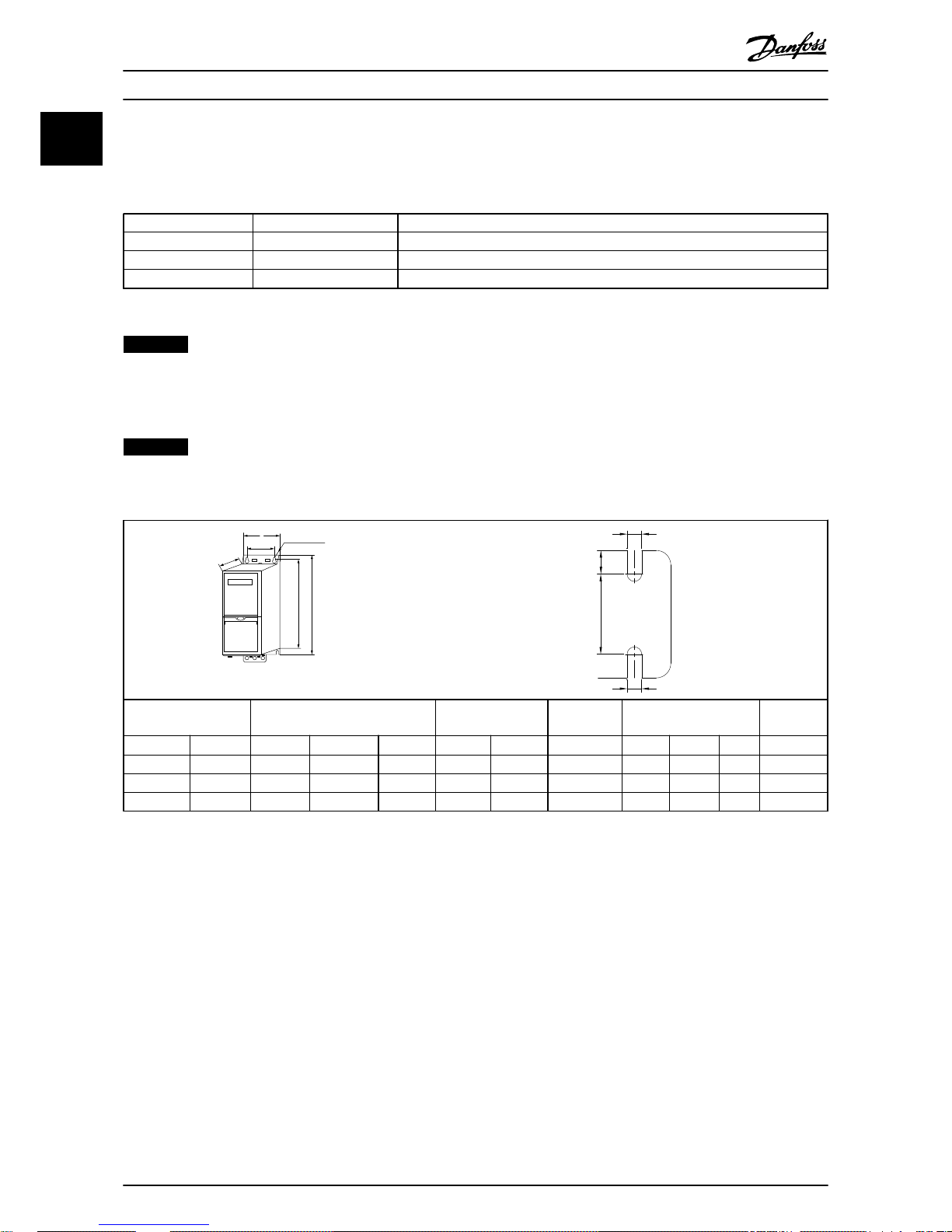
1.3.4 Dimensions
NOTICE
The illustration in Table 1.6 is with LCP, but all
dimensions are the same without LCP.
A
a
b
B
C
D
130BB614.10
e
f
a
e
130BC246.10
Enclosure Height [mm] Width [mm] Depth [mm] Mounting hole [mm] Max.
Weight
Frame IP Class A
A
1)
a B b C d e f kg
H3 IP20 255 329 240 100 74 206 11 5.5 8.1 4.5
H4 IP20 296 359 275 135 105 241 12.6 7 8.4 7.9
H5 IP20 334 402 314 150 120 255 12.6 7 8.5 9.5
Table 1.6 Dimensions
1) Including decoupling plate
The dimensions are only for the physical units, but when installing in an application it is necessary to add space for free air
passage both above and below the units. The amount of space for free air passage is listed in Table 1.5.
Quick Guide Quick Guide
4 Danfoss A/S © Rev. 09/2014 All rights reserved. MG18M102
1
Page 7
1.3.5 Electrical Installation in General
All cabling must comply with national and local regulations on cable cross-sections and ambient temperature. Copper
conductors required, (75 °C) recommended.
Enclosure Torque [Nm]
Frame IP class Line Compressor
connection
DC connection Control
terminals
Ground Relay
H3 IP20 1.4 0.8 0.8 0.5 0.8 0.5
H4 IP20 1.2 1.2 1.2 0.5 0.8 0.5
H5 IP20 1.2 1.2 1.2 0.5 0.8 0.5
Table 1.7 Enclosure H3-H5
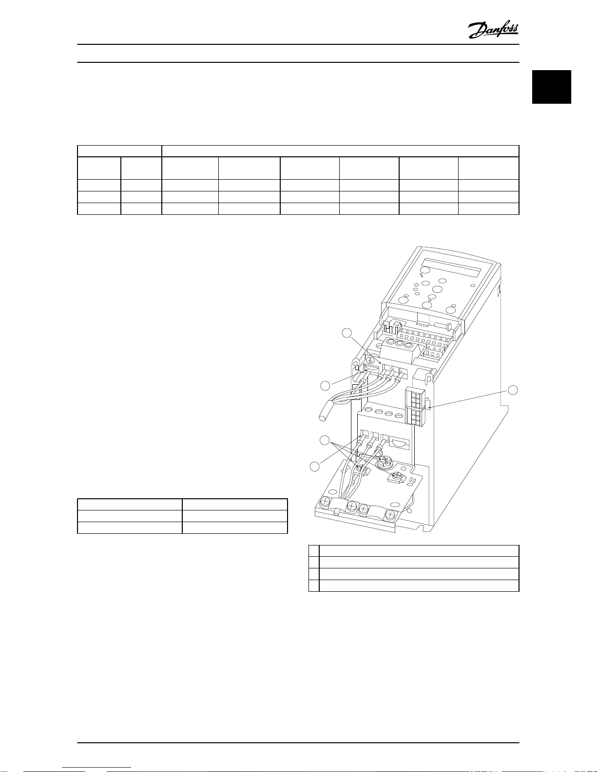
1.3.6
Connecting to Mains and Compressor
The frequency converter is designed to operate Danfoss
VZH Compressors. For maximum cross-section on wires see
chapter 1.7 General Specifications.
•
Use a shielded/armored compressor cable to
comply with EMC emission specifications, and
connect this cable to both the decoupling plate
and the compressor metal.
•
Keep compressor cable as short as possible to
reduce the noise level and leakage currents.
•
For further details on mounting of the
decoupling plate, see VLT® Compressor Drive CDS
803 Decoupling Plate Installation Instructions.
•
Also see EMC-Correct Installation in the VLT
®
Compressor Drive CDS 803 Design Guide.
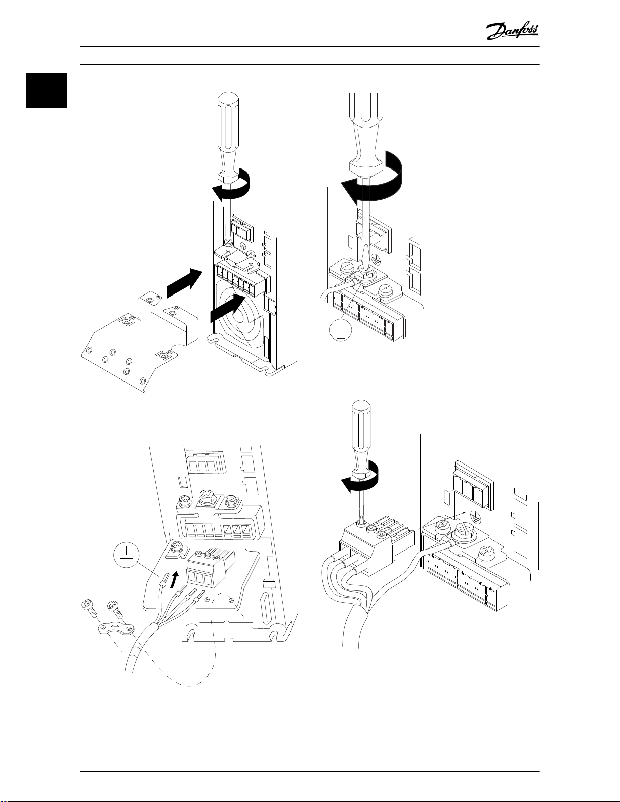
1. Mount the ground wires to ground terminal.
2. Connect compressor to terminals U, V and W, see
Table 1.8.
U
T1
V T2
W T3
Table 1.8 Connection of Compressor to Terminals
3. Mount mains supply to terminals L1, L2 and L3
and tighten.
130BB634.10
1
2
2
3
4
Motor
U
V
W
-DC
+DC
MAINS
1
Line
2 Ground
3 Compressor
4 Relays
Illustration 1.2 H3-H5 Frame
IP20 200-240 V 4-6.5 tons
IP20 380-480 V 4-6.5 tons
Quick Guide Quick Guide
MG18M102 Danfoss A/S © Rev. 09/2014 All rights reserved. 5
1
1
Page 8
-DC+DC
BR- BR+ U V W
99
M A I N S
95
RELAY 1 RELAY 2
- LC +
130BA261.10
Illustration 1.3 Mount the 2 screws in the mounting plate,
slide it into place and tighten fully.
MOTOR
MOTOR
U V W
99
130BT302.12
Illustration 1.4 H3-H5 Frame
130BA262.10
M
I N S
+DC
BR-
BR+
U
V
W
RELAY 1 RELAY 2
95
Illustration 1.5 When mounting cables, first mount and tighten
ground cable.
130BA263.10
95
M
A
INS
+DC
BR-
BR+
U
V
W
91
92
93
L1
L2
L3
RELAY 1 RELAY 2
Illustration 1.6 Mount mains plug and tighten wires.
Quick Guide Quick Guide
6 Danfoss A/S © Rev. 09/2014 All rights reserved. MG18M102
1
Page 9
+DC
BR-
BR+
U
V
W
MAINS
L1 L2 L3
91 92 93
RELAY 1 RELAY 2
99
- LC -
130BA264.10
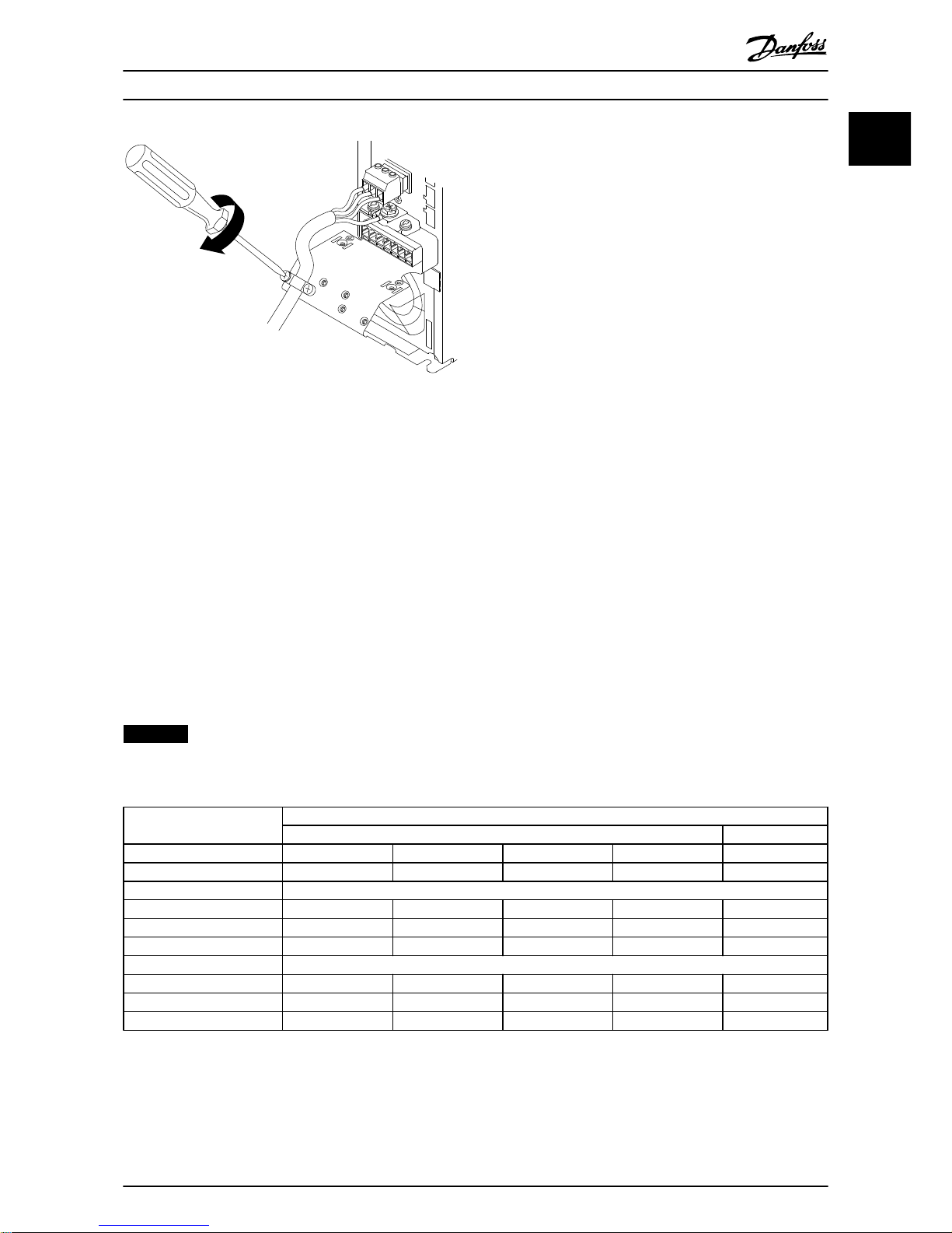
Illustration 1.7 Tighten support bracket on mains wires.
1.3.7
Fuses
Branch circuit protection
To protect the installation against electrical and fire hazard, all branch circuits in an installation, switch gear, machines etc.,
must be short-circuit and overcurrent protected according to national and local regulations.
Short circuit protection
Danfoss recommends using the fuses listed in Table 1.9 to protect service personnel or equipment in case of an internal
failure in the unit or short-circuit on DC-link. The frequency converter provides full short circuit protection in case of a shortcircuit on the compressor.
Overcurrent protection
Provide overload protection to avoid overheating of the cables in the installation. Overcurrent protection must always be
carried out according to local and national regulations. Circuit breakers and fuses must be designed for protection in a
circuit capable of supplying a maximum of 100,000 A
rms
(symmetrical), 480 V maximum.
UL/Non UL compliance
Use the fuses listed in Table 1.9 to ensure compliance with UL or IEC 61800-5-1.
NOTICE
In the event of malfunction, failure to follow the protection recommendation may result in damage to the frequency
converter.
Fuse
UL Non UL
Bussmann Bussmann Bussmann Bussmann Max fuse
CDS 803 Type RK5 Type RK1 Type J Type T Type G
3x200-240 V IP20
4 TR/VZH028 FRS-R-50 KTN-R50 JKS-50 JJN-50 50
5 TR/VZH035 FRS-R-50 KTN-R50 JKS-50 JJN-50 50
6.5 TR/VZH044 FRS-R-80 KTN-R80 JKS-80 JJN-80 65
3x380-480 V IP20
4 TR/VZH028 FRS-R-25 KTS-R25 JKS-25 JJS-25 25
5 TR/VZH035 FRS-R-25 KTS-R25 JKS-25 JJS-25 25
6.5 TR/VZH044 FRS-R-50 KTS-R50 JKS-50 JJS-50 50
Table 1.9 Fuses
Quick Guide Quick Guide
MG18M102 Danfoss A/S © Rev. 09/2014 All rights reserved. 7
1
1
Page 10
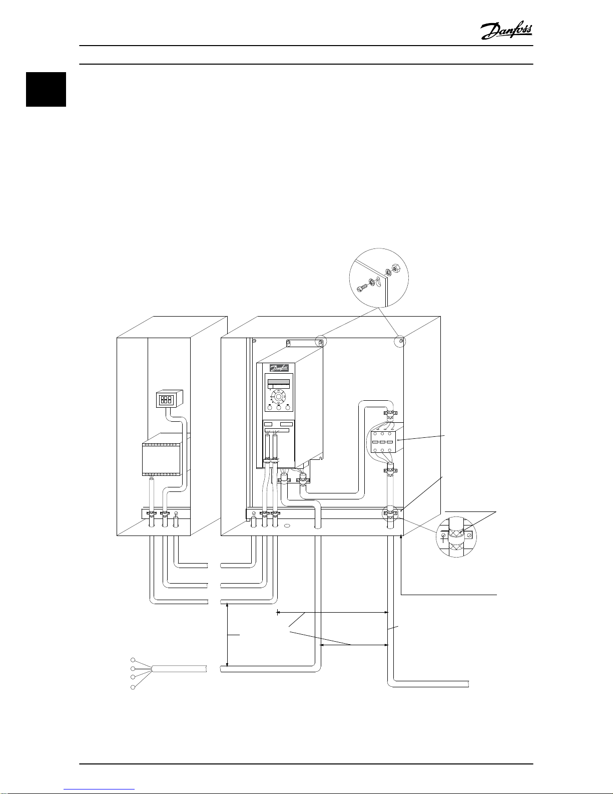
1.3.8 EMC-Correct Electrical Installation
General points to be observed to ensure EMC-correct electrical installation.
•
Use only screened/armoured motor cables and screened/armoured control cables.
•
Connect the screen to ground at both ends.
•
Avoid installation with twisted screen ends (pigtails), since this ruins the screening effect at high frequencies. Use
the cable clamps provided instead.
•
Ensure the same potential between frequency converter and ground potential of PLC.
•
Use starwashers and galvanically conductive installation plates.
B
a
c
k
OK
Com.
On
Warn.
Alarm
Hand
On
O
Reset
Auto
On
Menu
Status Quick
Menu
Main
Menu
L1
L2
L3
PE
Min. 16 mm
2
Equalizing cable
Control cables
All cable entries in
one side of panel
Earthing rail
Cable insulation stripped
Output contactor etc.
Motor cable
Motor, 3 phases and
PLC etc.
Panel
Mains-supply
Min. 200mm
between control
cable, mains cable
and between mains
motor cable
PLC
Protective earth
Reinforced protective earth
130BB761.11
Illustration 1.8 EMC-correct Electrical Installation
Quick Guide Quick Guide
8 Danfoss A/S © Rev. 09/2014 All rights reserved. MG18M102
1
Page 11

1.3.9 Control Terminals
130BB622.10
Illustration 1.9 Location of Control Terminals
1. Place a screwdriver behind the terminal cover to
activate the snap.
2. Tilt the screwdriver outwards to open the cover.
Control terminals
To make the compressor run:
1. Apply start signal on terminal 18
2. Connect terminals 12, 27 and terminal 53, 54 or
55
18
19
12 20 55
27 29 42 45 50 53 54
DIGI IN
DIGI IN
DIGI IN
DIGI IN
61 68 69
N
P
COMM. GND
+24V
0/4-20mA A OUT / DIG OUT 0/4-20mA A OUT / DIG OUT
GND
GND
10V/20mA IN
10V/20mA IN
10V OUT
130BB625.10
BUS TER.
OFF ON
Illustration 1.10 Control Terminals
Set the functions of digital input 18, 19 and 27 in
5-00 Digital Input Mode (PNP is default value). Set the
function of digital input 29 in 5-03 Digital Input 29 Mode
(PNP is default value).
Quick Guide Quick Guide
MG18M102 Danfoss A/S © Rev. 09/2014 All rights reserved. 9
1
1
Page 12

1.3.10 Electrical Overview
L1
L2
L3
3 Phase
power
input
PE
PE
+10 V DC
0-10 V DC-
0-10 V DC-
50 (+10 V OUT)
54 (A IN)
53 (A IN)
55 (COM A IN/OUT)
0/4-20 mA
0/4-20 mA
42 0/4-20 mA A OUT / DIG OUT
45 0/4-20 mA A OUT / DIG OUT
18 (DIGI IN)
19 (DIGI IN)
27 (DIGI IN)
29 (DIGI IN)
12 (+24 V OUT)
24 V (NPN)
20 (COM D IN)
O V (PNP)
24 V (NPN)
O V (PNP)
24 V (NPN)
O V (PNP)
24 V (NPN)
O V (PNP)
Bus ter.
Bus ter.
RS-485
Interface
RS-485
(N PS-485) 69
(P RS-485) 68
(Com RS-485 ) 61
(PNP)-Source
(NPN)-Sink
ON=Terminated
OFF=Unterminated
ON
1 2
240 V AC 3 A
Not present on all power sizes
Do not connect shield to 61
01
02
03
relay1
relay2
UDC+
UDC-
Motor
U
V
W
130BD467.10
06
05
04
240 V AC 3 A
Illustration 1.11 Basic Wiring Schematic Drawing
Quick Guide Quick Guide
10 Danfoss A/S © Rev. 09/2014 All rights reserved. MG18M102
1
Page 13

1.4 Programming
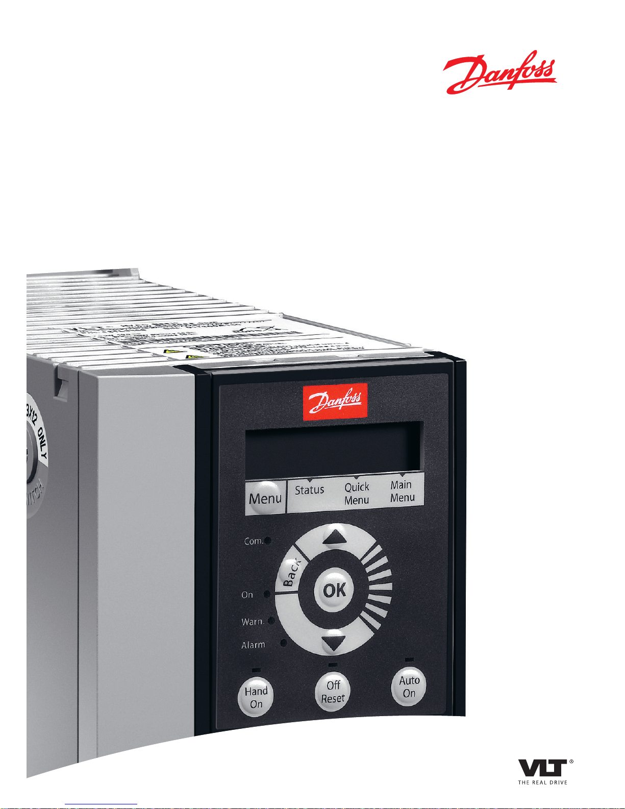
1.4.1 Local Control Panel (LCP)
NOTICE
LCP is NOT supported in SW 1.0X!
The LCP is divided into 4 functional sections.
A. Display
B. Menu key
C. Navigation keys and indicator lights (LEDs)
D. Operation keys and indicator lights (LEDs)
130BB765.11
Com.
1-20 Motor Power
[5] 0.37kW - 0.5HP
Setup 1
A
B
1
12
13 14 15
11
11
10
9
8
7
6
5
4
3
2
C
D
Status
Main
Menu
Quick
Menu
Hand
On
OK
Menu
Reset
Auto
On
Alarm
Warn.
On
11
Back
O
Illustration 1.12 Local Control Panel (LCP)
A. Display
The LCD-display is back-lit with 2 alphanumeric lines. All
data is displayed on the LCP.
Information can be read from the display.
1
Parameter number and name.
2 Parameter value.
3 Set-up number shows the active set-up and the edit set-
up. If the same set-up acts as both active and edit set-up,
only that set-up number is shown (factory setting). When
active and edit set-ups differ, both numbers are shown in
the display (set-up 12). The number flashing, indicates the
edit set-up.
4 Compressor direction is shown to the bottom left of the
display – indicated by a small arrow pointing either
clockwise or counterclockwise.
5 The triangle indicates if the LCP is in Status, Quick Menu
or Main Menu.
Table 1.10 Legend to Illustration 1.12
B. Menu key
Press [Menu] to select between Status, Quick Menu or
Main Menu.
C. Navigation keys and indicator lights (LEDs)
6 Com LED: Flashes when bus communication is communi-
cating.
7 Green LED/On: Control section is working.
8 Yellow LED/Warn.: Indicates a warning.
9 Flashing Red LED/Alarm: Indicates an alarm.
10 [Back]: For moving to the previous step or layer in the
navigation structure
11
[▲] [▼] [►]: For maneuvering between parameter groups,
parameters and within parameters. Can also be used for
setting local reference.
12 [OK]: For selecting a parameter and for accepting changes to
parameter settings
Table 1.11 Legend to Illustration 1.12
D. Operation keys and indicator lights (LEDs)
13
[Hand On]: Starts the compressor and enables control of
the frequency converter via the LCP.
NOTICE
Terminal 27 Digital Input (5-12 Terminal 27 Digital
Input) has stop inverse as default setting. This
means that [Hand On] does not start the
compressor if there is no 24 V to terminal 27.
Connect terminal 12 to terminal 27.
14 [Off/Reset]: Stops the compressor (Off). If in alarm mode,
the alarm is reset.
15 [Auto On]: Frequency converter is controlled either via
control terminals or serial communication.
Table 1.12 Legend to Illustration 1.12
Quick Guide
Quick Guide
MG18M102 Danfoss A/S © Rev. 09/2014 All rights reserved. 11
1
1
Page 14

1.4.2 The Start-up Wizard
The built-in wizard menu guides the installer through the
set-up of the frequency converter in a clear and structured
manner to set-up an open loop application. An open loop
application is here an application with a start signal,
analog reference (voltage or current) and optionally also
relay signals (but no feed back signal from the process
applied).
FC
+24 V
DIG IN
DIG IN
DIG IN
DIG IN
COM DIG IN
A OUT/D OUT
A OUT/D OUT
18
19
27
29
42
55
50
53
54
20
12
01
02
03
04
05
06
R2
R1
+
0-10 V
Start
+10 V
A IN
A IN
COM
130BD872.10
45
Reference
15
PRESSURE SWITCH
Illustration 1.13 Open Loop Application
The wizard is initially be shown after power-up until any
parameter has been changed. The wizard can always be
accessed again through the Quick Menu. Press [OK] to start
the wizard. Press [Back] to return to the status screen.
130BB629.10
Press OK to start Wizard
Push Back to skip it
Setup 1
Illustration 1.14 Start-up/Quit Wizard
Quick Guide Quick Guide
12 Danfoss A/S © Rev. 09/2014 All rights reserved. MG18M102
1
Page 15

English
OK
5
if
Select Language
... the CDS 803 Wizard starts
Size related
Select Grid Type
4
Select Main Menu Password
6
[0]
[0]
OK
B
a
c
k
Status
Main
Menu
Quick
Menu
Hand
On
OK
Menu
Reset
Auto
On
Alarm
Warn.
On
Status Screen
The Wizard can always be
reentered via the Quick Menu!
Power Up Screen
At power up the user is
asked to choose the
prefered laguage.
Select language
[1] English
0.0 Hz
0.0 kW
Setup 1
Setup 1
Status
Main
Menu
Quick
Menu
Hand
On
OK
Menu
Reset
Auto
On
Alarm
Warn.
On
Press OK to start Wizard
Press Back to skip it
Setup 1
Status
Main
Menu
Quick
Menu
Hand
On
OK
Menu
Reset
Auto
On
Alarm
Warn.
On
The next screen will be
the Wizard screen.
Wizard Screen
1
2
if
3
B
a
c
k
B
a
c
k
B
a
c
k
Com.
Com.
Com.
130BD873.11
Size related
Select Compressor Selection
7
200 Hz
Select Max. reference
8
Analog in 53
Select Reference 1 Source
9
[1]
30 s
Select Ramp 1 Ramp Up Time
10
30 s
Select Ramp 1 Ramp Down Time
11
Stop inverse
Select Terminal 27 Digital In
12
Alarm
Select Relay 1
13
Drive Running
Select Relay 2
14
0.07 V
Select Terminal 53 Low Voltage
15
10 V
Select Terminal 53 High Voltage
16
Digital and ctrl.word
Select Control Site
17
[0]
FC
Select Protocol
18
[0]
Setup 1
9600
Select Baud Rate
19
Setup 1
Setup 1
Setup 1
Setup 1
Setup 1
Setup 1
Setup 1
Setup 1
Setup 1
Setup 1
Setup 1
Setup 1
Setup 1
Setup 1
Setup 1
Quick Guide
Quick Guide
MG18M102 Danfoss A/S © Rev. 09/2014 All rights reserved. 13
1
1
Page 16

The Start-up Wizard for open loop applications
Parameter Option Default Function
0-01 Language
[0] English
[1] Deutsch
[2] Francais
[3] Dansk
[4] Spanish
[5] Italiano
[28] Bras.port
[0] English Select the language for the display.
0-06 GridType
[0] 200-240 V/50 Hz/IT-grid
[1] 200-240 V/50 Hz/Delta
[2] 200-240 V/50 Hz
[10] 380-440 V/50 Hz/IT-grid
[11] 380-440 V/50 Hz/Delta
[12] 380-440 V/50 Hz
[20] 440-480 V/50 Hz/IT-grid
[21] 440-480 V/50 Hz/Delta
[22] 440-480 V/50 Hz
[30] 525-600 V/50 Hz/IT-grid
[31] 525-600 V/50 Hz/Delta
[32] 525-600 V/50 Hz
[100] 200-240 V/60 Hz/IT-grid
[101] 200-240 V/60 Hz/Delta
[102] 200-240 V/60 Hz
[110] 380-440 V/60 Hz/IT-grid
[111] 380-440 V/60 Hz/Delta
[112] 380-440 V/60 Hz
[120] 440-480 V/60 Hz/IT-grid
[121] 440-480 V/60 Hz/Delta
[122] 440-480 V/60 Hz
[130] 525-600 V/60 Hz/IT-grid
[131] 525-600 V/60 Hz/Delta
[132] 525-600 V/60 Hz
Size related
Select operating mode for restart upon
reconnection of the frequency converter to
mains voltage after power down.
0-60 Main Menu Password
0-999 0 Define the password for access to the LCP.
1-13 Compressor Selection
[24] VZH028-R410A
[25] VZH035-R410A
[26] VZH044-R410A
Size related Select the used compressor.
3-03 Maximum Reference
0-200 Hz 200 Hz The maximum reference is the lowest
obtainable by summing all references.
3-15 Reference 1 Source
[0] No function
[1] Analog in 53
[2] Analog in 54
[7] Pulse input 29
[11] Local bus reference
[1] Analog in 53 Select the input to be used for the reference
signal.
3-41 Ramp 1 Ramp Up Time
0.05-3600.0 s 30.00 s
Ramp-up time from 0 to 1-25 Motor Nominal
Speed.
3-42 Ramp 1 Ramp Down Time
0.05-3600.0 s 30.00 s Ramp down time from rated motor speed to
0.
Quick Guide Quick Guide
14 Danfoss A/S © Rev. 09/2014 All rights reserved. MG18M102
1
Page 17

Parameter Option Default Function
5-12 Terminal 27 Digital Input
[0] No operation
[1] Reset
[2] Coast inverse
[3] Coast and reset inverse
[4] Quick stop inverse
[5] DC-brake inverse
[6] Stop inverse
[7] External Interlock
[8] Start
[9] Latched start
[10] Reversing
[11] Start reversing
[14] Jog
[16] Preset ref bit 0
[17] Preset ref bit 1
[18] Preset ref bit 2
[19] Freeze reference
[20] Speed up
[22] Speed down
[23] Set-up select bit 0
[34] Ramp bit 0
[52] Run permissive
[53] Hand start
[54] Auto start
[60] Counter A (up)
[61] Counter A (down)
[62] Reset Counter A
[63] Counter B (up)
[64] Counter B (down)
[65] Reset Counter B
[6] Stop inverse
Select the input function for terminal 27.
5-40 Function Relay [0] Function relay
See 5-40 Function Relay Alarm Select the function to control output relay 1.
5-40 Function Relay [1] Function relay
See 5-40 Function Relay Drive running Select the function to control output relay 2.
6-10 Terminal 53 Low Voltage
0-10 V 0.07 V Enter the voltage that corresponds to the low
reference value.
6-11 Terminal 53 High Voltage
0-10 V 10 V Enter the voltage that corresponds to the
high reference value.
8-01 Control Site
[0] Digital and ctrl.word
[1] Digital only
[2] Controlword only
[0] Digital and
ctrl. word
Select if digital, bus, or a combination of both
should control the frequency converter.
8-30 Protocol
[0] FC
[2] Modbus RTU
[0] FC Select the protocol for the integrated RS-485
port.
8-32 Baud Rate
[0] 2400 Baud [1]
4800 Baud
*[2] 9600 Baud
[3] 19200 Baud
4] 38400 Baud
5] 57600 Baud
[6] 76800 Baud
[7] 115200 Baud
9600 Select the baud rate for the RS-485 port.
Table 1.13 Open Loop Applications Set-up
Quick Guide
Quick Guide
MG18M102 Danfoss A/S © Rev. 09/2014 All rights reserved. 15
1
1
Page 18

The Start-up Wizard for compressor functions
28-13 Boost Duration
60 s
5
6
28-01 Interval between Starts
130BD874.11
28-11 Low Speed Running Time
20 min
28-02 Minimum Run Time
3
28-00 Short Cycle Protection
[1]
Enabled
1
28-10 Oil Return Management
[1]
On
4
2
300 s
60 s
Illustration 1.16 Compressor Function Wizard
Compressor function wizard
Parameter Option Default Function
28-00 Short Cycle Protection
[0] Disabled
[1] Enabled
[1] Enabled Select if short cycle protection is to be used.
28-01 Interval between Starts
0-3600 s 300 s Enter the minimum allowed time between
starts.
28-02 Minimum Run Time
10-3600 s 60 s Enter the minimum allowed time to run
before stop.
28-10 Oil Return Management
[0] Off
[1] On
[1] On Select if Oil Return Management is to be used.
28-11 Low Speed Running Time
1-1400 min 20 min Enter the low speed running time.
28-13 Boost Duration
10-3600 s 60 s Enter the boost duration for the oil return.
Table 1.14 Compressor Function
Quick Guide Quick Guide
16 Danfoss A/S © Rev. 09/2014 All rights reserved. MG18M102
1
Page 19

The Start-up Wizard for compressor closed loop applications
6-24 Terminal 54 Low Ref./Feedb.
0
6-23 Terminal 54 High Voltage
6-22 Terminal 54 Low Voltage
0.07
6-15 Terminal 53 High Ref./Feedb.
200
6-10/12 Terminal 53 Low Voltage
0003
s
6-11 Terminal 53 High Voltage
13
14
15
16
18
19
21
22
5-40 Function Relay 1
5-40 Function Relay 2
Drive running
130BD875.11
6-25 Terminal 54 High Ref./Feedb.
0-60 Main Menu Password
[0]
3
0-01 Language
[0]
English
1
4
2
0-06 Grid Type
Size related
3-10 Preset Reference
0%
3-02 Minimum Reference
0
Hz
1-00 Conguration Mode
Open loop
3-03 Maximum Reference
200
3-42 Ramp 1 Ramp Down Time
5
5-12 Terminal 27 Digital Input
3-41 Ramp 1 Ramp Up Time
5
6
7
8
9
10
11
12
3-15 Reference 1 Source
6-14 Terminal 53 Low Ref./Feedb.
30
17
20
8-30 Protocol
[0]
FC
8-01 Control Site
20-81 Normal/Inverse Control
20-00 Feedback 1 Source
0.00
23
24
26
27
8-32 Baud Rate
Digital and ctrl.word
25
[0]
Hz
Analog in 53
[1]
10
V
[0]
30.00
s
30.00
s
Stop inverse
[6]
V
10.00
V
50.000
No function
[0]
Normal
[0]
9600
1-13 Compressor Selection
Size related
Alarm
Illustration 1.17 Closed Loop Wizard
Quick Guide
Quick Guide
MG18M102 Danfoss A/S © Rev. 09/2014 All rights reserved. 17
1
1
Page 20

Closed loop wizard
Parameter Option Default Function
0-01 Language
[0] English
[1] Deutsch
[2] Francais
[3] Dansk
[4] Spanish
[5] Italiano
[28] Bras.port
0 Select the language for the display.
0-06 GridType
[0] 200-240 V/50 Hz/IT-grid
[1] 200-240 V/50 Hz/Delta
[2] 200-240 V/50 Hz
[10] 380-440 V/50 Hz/IT-grid
[11] 380-440 V/50 Hz/Delta
[12] 380-440 V/50 Hz
[20] 440-480 V/50 Hz/IT-grid
[21] 440-480 V/50 Hz/Delta
[22] 440-480 V/50 Hz
[30] 525-600 V/50 Hz/IT-grid
[31] 525-600 V/50 Hz/Delta
[32] 525-600 V/50 Hz
[100] 200-240 V/60 Hz/IT-grid
[101] 200-240 V/60 Hz/Delta
[102] 200-240 V/60 Hz
[110] 380-440 V/60 Hz/IT-grid
[111] 380-440 V/60 Hz/Delta
[112] 380-440 V/60 Hz
[120] 440-480 V/60 Hz/IT-grid
[121] 440-480 V/60 Hz/Delta
[122] 440-480 V/60 Hz
[130] 525-600 V/60 Hz/IT-grid
[131] 525-600 V/60 Hz/Delta
[132] 525-600 V/60 Hz
Size related
Select the operating mode for restart upon
reconnection of the frequency converter to
mains voltage after power down.
0-60 Main Menu Password
0-999 0 Define the password for access to the LCP.
1-00 Configuration Mode
[0] Open loop
[3] Closed loop
[0] Open loop Select closed loop.
1-13 Compressor Selection
[24] VZH028
[25] VZH035
[26] VZH044
Size related Select the used compressor.
3-02 Minimum Reference
-4999.0 - 200 Hz 0 Hz The minimum reference is the lowest value
obtainable by summing all references.
3-03 Maximum Reference
0 - 200 Hz 200 Hz The maximum reference is the highest
obtainable by summing all references
3-10 Preset Reference
-100 - 100 % 0 % Setup a fix set point n preset reference [0].
3-15 Reference 1 Source
[0] No function
[1] Analog in 53
[2] Analog in 54
[7] Pulse input 29
[11] Local bus reference
[1] Analog in 53 Select the input to be used for the reference
signal.
3-41 Ramp 1 Ramp Up Time
0.05-3600.0 s 30.00 s
Ramp up time from 0 to 1-25 Motor Nominal
Speed.
3-42 Ramp 1 Ramp Down Time
0.05-3600.0 s 30.00 s Ramp-down time from rated motor speed to
0.
Quick Guide Quick Guide
18 Danfoss A/S © Rev. 09/2014 All rights reserved. MG18M102
1
Page 21

Parameter Option Default Function
5-12 Terminal 27 Digital Input
[0] No operation
[1] Reset
[2] Coast inverse
[3] Coast and reset inverse
[4] Quick stop inverse
[5] DC-brake inverse
[6] Stop inverse
[7] External Interlock
[8] Start
[9] Latched start
[10] Reversing
[11] Start reversing
[14] Jog
[16] Preset ref bit 0
[17] Preset ref bit 1
[18] Preset ref bit 2
[19] Freeze reference
[20] Speed up
[22] Speed down
[23] Set-up select bit 0
[34] Ramp bit 0
[52] Run permissive
[53] Hand start
[54] Auto start
[60] Counter A (up)
[61] Counter A (down)
[62] Reset Counter A
[63] Counter B (up)
[64] Counter B (down)
[65] Reset Counter B
[6] Stop inverse
Select the input function for terminal 27.
5-40 Function Relay [0] Function relay
See 5-40 Function Relay Alarm Select the function to control output relay 1.
5-40 Function Relay [1] Function relay
See 5-40 Function Relay Drive running Select the function to control output relay 2.
6-10 Terminal 53 Low Voltage
0-10 V 0.07 V Enter the voltage that corresponds to the low
reference value.
6-11 Terminal 53 High Voltage
0-10 V 10 V Enter the voltage that corresponds to the
high reference value.
6-14 Terminal 53 Low Ref./Feedb.
Value
-4999 - 4999 30 Enter the reference value that corresponds to
the voltage set in 6-10 Terminal 53 Low
Voltage.
6-15 Terminal 53 High Ref./Feedb.
Value
-4999 - 4999 200 Enter the reference value that corresponds to
the voltage set in 6-11 Terminal 53 High
Voltage.
6-22 Terminal 54 Low Current
0.00-20.00 mA 4.00 mA Enter the current that corresponds to the low
reference value.
6-23 Terminal 54 High Current
0-10 V 10 V Enter the current that corresponds to the high
reference value.
6-24 Terminal 54 Low Ref./Feedb.
Value
-0.00-20.00 mA 20.00 mA Enter the reference value that corresponds to
the current set in 6-20 Terminal 54 Low
Voltage.
6-25 Terminal 54 High Ref./Feedb.
Value
-4999 - 4999 Size related Enter the reference value that corresponds to
the current set in 6-21 Terminal 54 High
Voltage.
8-01 Control Site
[0] Digital and ctrl.word
[1] Digital only
[2] Controlword only
0 Select if digital, bus, or a combination of both
should control the frequency converter.
Quick Guide Quick Guide
MG18M102 Danfoss A/S © Rev. 09/2014 All rights reserved. 19
1
1
Page 22

Parameter Option Default Function
8-30 Protocol
[0] FC
[2] Modbus RTU
0 Select the protocol for the integrated RS-485
port.
8-32 Baud Rate
[0] 2400 Baud
[1] 4800 Baud
[2] 9600 Baud
[3] 19200 Baud
[4] 38400 Baud
[5] 57600 Baud
[6] 76800 Baud
[7] 115200 Baud
[2] 9600 Baud Select the baud rate for the RS-485 port.
20-00 Feedback 1 Source
[0] No function
[1] Analog Input 53
[2] Analog Input 54
[3] Pulse input 29
[100] Bus Feedback 1
[101] Bus Feedback 2
[0] No function Select which input will be used as the source
of the feedback signal.
20-81 PI Normal/ Inverse Control
[0] Normal
[1] Inverse
[0] Normal Select how the feedback should be calculated
Table 1.15 Closed Loop Applications Set-up
Changes made
Changes Made lists all parameters changed from default
settings.
•
The list shows only parameters which have been
changed in the current edit-setup.
•
Parameters which have been reset to default
values are not listed.
•
The message Empty indicates that no parameters
have been changed.
To change parameter settings
1. Press [Menu] key to enter the Quick Menu until
indicator in display is placed above Quick Menu.
2.
Press [▲] [▼] to select wizard, closed loop set-up,
compressor set-up or changes made, then press
[OK].
3.
Press [▲] [▼] to browse through the parameters
in the Quick Menu.
4. Press [OK] to select a parameter.
5.
Press [▲] [▼] to change the value of a parameter
setting.
6. Press [OK] to accept the change.
7. Press either [Back] twice to enter Status, or press
[Menu] once to enter Main Menu.
The Main Menu accesses all parameters
1. Press [Menu] until indicator in display is placed
above Main Menu.
2.
Press [▲] [▼] to browse through the parameter
groups.
3. Press [Ok] to select a parameter group.
4.
Press [▲] [▼] to browse through the parameters
in the specific group.
5. Press [Ok] to select the parameter.
6.
Press [▲] [▼] to set/change the parameter value.
Quick Guide Quick Guide
20 Danfoss A/S © Rev. 09/2014 All rights reserved. MG18M102
1
Page 23

1.4.3 Main Menu
Structure
0-** Operation / Display
0-0* Basic Settings
0-01 Language
0-03 Regional Settings
0-04 Operating State at Power-up
0-06 GridType
0-07 Auto DC Braking
0-1* Set-up Operations
0-10 Active Set-up
0-11 Programming Set-up
0-12 Link Setups
0-3* LCP Custom Readout
0-30 Custom Readout Unit
0-31 Custom Readout Min Value
0-32 Custom Readout Max Value
0-4* LCP Keypad
0-40 [Hand on] Key on LCP
0-42 [Auto on] Key on LCP
0-44 [Off/Reset] Key on LCP
0-5* Copy/Save
0-50 LCP Copy
0-51 Set-up Copy
0-6* Password
0-60 Main Menu Password
1-** Load and Motor
1-1* Motor Selection
1-10 Motor Construction
1-13 Compressor Selection
1-9* Motor Temperature
1-90 Motor Thermal Protection
1-93 Thermistor Source
3-** Reference / Ramps
3-0* Reference Limits
3-02 Minimum Reference
3-03 Maximum Reference
3-1* References
3-10 Preset Reference
3-11 Jog Speed [Hz]
3-14 Preset Relative Reference
3-15 Reference 1 Source
3-16 Reference 2 Source
3-17 Reference 3 Source
3-4* Ramp 1
3-41 Ramp 1 Ramp Up Time
3-42 Ramp 1 Ramp Down Time
3-5* Ramp 2
3-51 Ramp 2 Ramp Up Time
3-52 Ramp 2 Ramp Down Time
3-8* Other Ramps
3-80 Jog Ramp Time
3-81 Quick Stop Ramp Time
4-** Limits / Warnings
4-1* Motor Limits
4-14 Motor Speed High Limit [Hz]
4-18 Current Limit
4-19 Max Output Frequency
4-4* Adj. Warnings 2
4-40 Warning Freq. Low
4-41 Warning Freq. High
4-5* Adj. Warnings
4-50 Warning Current Low
4-51 Warning Current High
4-54 Warning Reference Low
4-55 Warning Reference High
4-56 Warning Feedback Low
4-57 Warning Feedback High
4-58 Missing Motor Phase Function
4-6* Speed Bypass
4-61 Bypass Speed From [Hz]
4-63 Bypass Speed To [Hz]
4-64 Semi-Auto Bypass Set-up
5-** Digital In/Out
5-0* Digital I/O mode
5-00 Digital Input Mode
5-1* Digital Inputs
5-10 Terminal 18 Digital Input
5-11 Terminal 19 Digital Input
5-12 Terminal 27 Digital Input
5-13 Terminal 29 Digital Input
5-3* Digital Outputs
5-34 On Delay, Digital Output
5-35 Off Delay, Digital Output
5-4* Relays
5-40 Function Relay
5-41 On Delay, Relay
5-42 Off Delay, Relay
5-5* Pulse Input
5-50 Term. 29 Low Frequency
5-51 Term. 29 High Frequency
5-52 Term. 29 Low Ref./Feedb. Value
5-53 Term. 29 High Ref./Feedb. Value
5-9* Bus Controlled
5-90 Digital & Relay Bus Control
6-** Analog In/Out
6-0* Analog I/O Mode
6-00 Live Zero Timeout Time
6-01 Live Zero Timeout Function
6-1* Analog Input 53
6-10 Terminal 53 Low Voltage
6-11 Terminal 53 High Voltage
6-12 Terminal 53 Low Current
6-13 Terminal 53 High Current
6-14 Terminal 53 Low Ref./Feedb. Value
6-15 Terminal 53 High Ref./Feedb. Value
6-16 Terminal 53 Filter Time Constant
6-19 Terminal 53 mode
6-2* Analog Input 54
6-20 Terminal 54 Low Voltage
6-21 Terminal 54 High Voltage
6-22 Terminal 54 Low Current
6-23 Terminal 54 High Current
6-24 Terminal 54 Low Ref./Feedb. Value
6-25 Terminal 54 High Ref./Feedb. Value
6-26 Terminal 54 Filter Time Constant
6-29 Terminal 54 mode
6-7* Analog/Digital Output 45
6-70 Terminal 45 Mode
6-71 Terminal 45 Analog Output
6-72 Terminal 45 Digital Output
6-73 Terminal 45 Output Min Scale
6-74 Terminal 45 Output Max Scale
6-76 Terminal 45 Output Bus Control
6-9* Analog/Digital Output 42
6-90 Terminal 42 Mode
6-91 Terminal 42 Analog Output
6-92 Terminal 42 Digital Output
6-93 Terminal 42 Output Min Scale
6-94 Terminal 42 Output Max Scale
6-96 Terminal 42 Output Bus Control
8-** Comm. and Options
8-0* General Settings
8-01 Control Site
8-02 Control Source
8-03 Control Timeout Time
8-04 Control Timeout Function
8-3* FC Port Settings
8-30 Protocol
8-31 Address
8-32 Baud Rate
8-33 Parity / Stop Bits
8-35 Minimum Response Delay
8-36 Maximum Response Delay
8-37 Maximum Inter-char delay
8-4* FC MC protocol set
8-42 PCD Write Configuration
8-43 PCD Read Configuration
8-5* Digital/Bus
8-50 Coasting Select
8-51 Quick Stop Select
8-52 DC Brake Select
8-53 Start Select
8-54 Reversing Select
8-55 Set-up Select
8-56 Preset Reference Select
8-8* FC Port Diagnostics
8-80 Bus Message Count
8-81 Bus Error Count
8-82 Slave Messages Rcvd
8-83 Slave Error Count
8-84 Slave Messages Sent
8-85 Slave Timeout Errors
8-88 Reset FC port Diagnostics
8-9* Bus Jog / Feedback
8-94 Bus Feedback 1
8-95 Bus Feedback 2
13-** Smart Logic
13-0* SLC Settings
13-00 SL Controller Mode
13-01 Start Event
13-02 Stop Event
13-03 Reset SLC
13-1* Comparators
13-10 Comparator Operand
13-11 Comparator Operator
13-12 Comparator Value
13-2* Timers
13-20 SL Controller Timer
13-4* Logic Rules
13-40 Logic Rule Boolean 1
13-41 Logic Rule Operator 1
13-42 Logic Rule Boolean 2
13-43 Logic Rule Operator 2
13-44 Logic Rule Boolean 3
13-5* States
13-51 SL Controller Event
13-52 SL Controller Action
14-** Special Functions
14-0* Inverter Switching
14-01 Switching Frequency
14-03 Overmodulation
14-1* Mains On/Off
14-12 Function at Mains Imbalance
14-2* Reset Functions
14-20 Reset Mode
14-21 Automatic Restart Time
14-22 Operation Mode
14-23 Typecode Setting
14-29 Service Code
14-5* Environment
14-50 RFI Filter
14-6* Auto Derate
14-65 Speed Derate Dead Time Compen-
sation
14-9* Fault Settings
14-90 Fault Level
15-** Drive Information
15-0* Operating Data
15-00 Operating hours
15-01 Running Hours
15-03 Power Up's
15-04 Over Temp's
15-05 Over Volt's
15-06 Reset kWh Counter
15-07 Reset Running Hours Counter
15-08 Number of Starts
15-09 Number of Auto Resets
15-3* Alarm Log
15-30 Alarm Log: Error Code
15-31 InternalFaultReason
15-4* Drive Identification
15-40 FC Type
15-41 Power Section
15-42 Voltage
15-43 Software Version
15-44 Ordered TypeCode
15-45 Actual Typecode String
15-46 Drive Ordering No
15-48 LCP Id No
15-49 SW ID Control Card
15-50 SW ID Power Card
15-51 Drive Serial Number
15-53 Power Card Serial Number
15-59 File name
15-9* Parameter Info
15-92 Defined Parameters
15-97 Application Type
15-98 Drive Identification
16-** Data Readouts
16-0* General Status
16-00 Control Word
16-01 Reference [Unit]
16-02 Reference [%]
16-03 Status Word
16-05 Main Actual Value [%]
16-09 Custom Readout
16-1* Motor Status
16-10 Power [kW]
16-11 Power [hp]
16-12 Motor Voltage
16-13 Frequency
16-14 Motor current
16-15 Frequency [%]
16-16 Torque [Nm]
16-18 Motor Thermal
16-22 Torque [%]
16-3* Drive Status
16-30 DC Link Voltage
16-34 Heatsink Temp.
16-35 Inverter Thermal
16-36 Inv. Nom. Current
16-37 Inv. Max. Current
16-38 SL Controller State
16-5* Ref. & Feedb.
16-50 External Reference
16-52 Feedback[Unit]
16-54 Feedback 1 [Unit]
16-55 Feedback 2 [Unit]
16-6* Inputs & Outputs
16-60 Digital Input
16-61 Terminal 53 Setting
16-62 Analog Input AI53
16-63 Terminal 54 Setting
16-64 Analog Input AI54
16-65 Analog Output AO42 [mA]
16-66 Digital Output
16-67 Pulse Input #29 [Hz]
16-71 Relay Output [bin]
16-72 Counter A
16-73 Counter B
16-79 Analog Output AO45
16-8* Fieldbus & FC Port
16-86 FC Port REF 1
16-9* Diagnosis Readouts
16-90 Alarm Word
16-91 Alarm Word 2
16-92 Warning Word
16-93 Warning Word 2
16-94 Ext. Status Word
16-95 Ext. Status Word 2
Quick Guide Quick Guide
MG18M102 Danfoss A/S © Rev. 09/2014 All rights reserved. 21
1
1
Page 24

20-** Drive Closed Loop
20-0* Feedback
20-00 Feedback 1 Source
20-01 Feedback 1 Conversion
20-03 Feedback 2 Source
20-04 Feedback 2 Conversion
20-2* Feedback/Setpoint
20-20 Feedback Function
20-8* PI Basic Settings
20-81 PI Normal/ Inverse Control
20-83 PI Start Speed [Hz]
20-84 On Reference Bandwidth
20-9* PI Controller
20-91 PI Anti Windup
20-93 PI Proportional Gain
20-94 PI Integral Time
20-97 PI Feed Forward Factor
28-** Compressor Functions
28-0* Short Cycle Protection
28-00 Short Cycle Protection
28-01 Interval between Starts
28-02 Minimum Run Time
28-1* Oil Return Management
28-10 Oil Return Management
28-11 Low Speed Running Time
28-13 Boost Duration
28-15 ORM Min Speed Limit [Hz]
28-17 ORM Boost Speed [Hz]
28-4* Anti-reverse Protection at Stop
28-40 Reverse Protection Control
28-6* Compressor Readouts
28-60 RPS
Quick Guide Quick Guide
22 Danfoss A/S © Rev. 09/2014 All rights reserved. MG18M102
1
Page 25

1.5 Acoustic Noise or Vibration
If the compressor is making noise or vibrations at certain frequencies, try the following:
•
Speed Bypass, parameter group 4-6* Speed Bypass
1.6 Warnings and Alarms
Fault
number
Alarm/
Warning Bit
Number
Fault text Warning Alarm Trip
locked
Cause of problem
2 16 Live zero error X X
Signal on terminal 53 or 54 is less than 50% of the value set
in 6-10 Terminal 53 Low Voltage, 6-12 Terminal 53 Low Current,
6-20 Terminal 54 Low Voltageor 6-22 Terminal 54 Low Current.
See also parameter group 6-0* Analog I/O Mode.
4 14 Mains ph. loss X X X
Missing phase on the supply side or too high voltage
imbalance. Check the supply voltage. See 14-12 Function at
Mains Imbalance.
7 11 DC over volt X X Intermediate circuit voltage exceeds limit.
8 10 DC under volt X X
Intermediate circuit voltage drops below “voltage warning
low” limit.
9 9 Inverter overload X X More than 100% load for too long.
10 8 Motor ETR over X X
The motor is too hot due to more than 100% load for too
long. See 1-90 Motor Thermal Protection
11 7 Motor th over X X
The thermistor or the thermistor connection is disconnected.
See 1-90 Motor Thermal Protection.
13 5 Over Current X X X Inverter peak current limit is exceeded.
14 2 Earth Fault X X Discharge from output phases to ground.
16 12 Short Circuit X X
Short-circuit in the compressor or on the compressor
terminals.
17 4 Ctrl. word TO X X
No communication to the frequency converter. See
parameter group 8-0* General Settings.
18 Start failed X
The speed has not been able to exceed 1-78 Compressor Start
Min Speed [Hz] during start within the allowed time.
30 19 U phase loss X X
Motor phase U is missing. Check the phase. See 4-58 Missing
Motor Phase Function.
31 20 V phase loss X X
Motor phase V is missing. Check the phase. See 4-58 Missing
Motor Phase Function.
32 21 W phase loss X X
Motor phase W is missing. Check the phase. See 4-58 Missing
Motor Phase Function.
38 17 Internal fault X X Contact the local Danfoss supplier.
44 28 Earth Fault X X
Discharge from output phases to ground, using the value of
15-31 Alarm Log Value if possible.
47 23
Control Voltage
Fault
X X X
24 V DC may be overloaded.
48 25 VDD1 supply low X X Control voltage low. Contact the local Danfoss supplier
49 X
The speed is below the specified limit in 1-87 Compressor
Min. Speed for Trip [Hz].
58 AMA internal X X Contact the local Danfoss supplier.
59 25 Current limit X
The current is higher than the value in 4-18 Current Limit.
60 44 External Interlock X
External interlock has been activated. To resume normal
operation, apply 24 V DC to the terminal programmed for
external interlock and reset the frequency converter (via
serial communication, digital I/O, or by pressing [Off/Reset]).
Quick Guide Quick Guide
MG18M102 Danfoss A/S © Rev. 09/2014 All rights reserved. 23
1
1
Page 26

Fault
number
Alarm/
Warning Bit
Number
Fault text Warning Alarm Trip
locked
Cause of problem
69 1 Pwr. Card Temp X X X
The temperature sensor on the power card is either too hot
or too cold.
79
Illegal power
section configuration
X X
Internal fault. Contact the local Danfoss supplier.
80 29 Drive initialised X All parameter settings are initialised to default settings.
87 47 Auto DC Braking X The frequency converter is auto DC braking
126 Motor Rotating X High back-emf voltage. Stop the rotor of the PM motor.
250 New sparepart X X
The power or switch mode power supply has been
exchanged. (Only on 400 V 30-90 kW units). Contact the local
Danfoss supplier
251 New Typecode X X
The frequency converter has a new type code (Only on 400 V
30-90 kW units). Contact the local Danfoss supplier.
Table 1.16 Warnings and Alarms
1.7 General Specifications
1.7.1 Mains Supply 3x200-240 V AC
Frequency converter 4 TR/VZH028 5 TR/VZH035 6.5 TR/VZH044
Typical shaft output [kW] 6.0 7.5 10
IP20 enclosure protection H4 H4 H5
Maximum cable size in terminals (mains, compressor) [mm2/AWG]
16/6 16/6 16/6
Output current
Continuous
(3x200-240 V) [A]
20.7 25.9 33.7
Intermittent
(3x200-240 V) [A]
- - 37.1
Maximum input current
Continuous
3x200-240 V) [A]
23.0 28.3 37.0
Intermittent
(3x200-240 V) [A]
- - 41.5
Maximum mains fuses, see Table 1.9
Estimated power loss [W], Best case/typical
1)
182/
204
229/
268
369/
386
Weight enclosure protection P20 [kg] 7.9 7.9 9.5
Efficiency [%], best case/
typical
1)
97.3/
97.0
98.5/
97.1
97.2/
97.1
Table 1.17 3x200-240 V AC
1) At rated load conditions
Quick Guide Quick Guide
24 Danfoss A/S © Rev. 09/2014 All rights reserved. MG18M102
1
Page 27

1.7.2 Mains Supply 3x380-480 V AC
Frequency converter 4 TR/VZH028 5 TR/VZH035 6.5 TR/VZH044
Typical shaft output [kW] 6.0 7.5 10
IP20 enclosure protection H3 H3 H4
Maximum cable size in terminals (mains, compressor) [mm2/AWG]
4/10 4/10 16/6
Output current
Continuous (3x380-440 V) [A] 11.6 14.3 16.4
Intermittent (3x380-440 V) [A] 18.0
Continuous (3x440-480 V) [A] 9.8 12.3 15.5
Intermittent (3x440-480 V) [A] 17.0
Maximum input current
Continuous (3x380-440 V) [A] 12.7 15.5 18.0
Intermittent (3x380-440 V) [A] 19.8
Continuous (3x440-480 V) [A] 10.8 13.5 17.0
Intermittent (3x440-480 V) [A] 18.7
Maximum mains fuses
Estimated power loss [W],
best case/typical
1)
104/131 159/198 248/274
Weight enclosure protection IP20 [kg] 4.3 4.5 7.9
Efficiency [%],
best case/typical
1)
98.4/98.0 98.2/97.8 98.1/97.9
Table 1.18 3x380-480 V AC
1) At rated load conditions
Quick Guide Quick Guide
MG18M102 Danfoss A/S © Rev. 09/2014 All rights reserved. 25
1
1
Page 28

1.7.3 EMC Test Results
The following test results have been obtained using a system with a frequency converter, a screened control cable, a control
box with potentiometer, as well as a compressor screened cable.
RFI
Filter
Type
Conduct emission. Maximum shielded cable length [m] Radiated emission
Industrial environment
Housing, trades and light
industries
Industrial
environment
Housing, trades and
light industries
EN 55011 Class A2 EN 55011 Class A1 EN 55011 Class B EN 55011 Class A1 EN 55011 Class B
Without
external
filter
With
external
filter
Without
external
filter
With
external
filter
Without
external
filter
With
external
filter
Without
external
filter
With
external
filter
Without
external
filter
With
external
filter
H4 RFI filter (Class A1)
CDS
803
IP20
25 50 20 Yes Yes No
Table 1.19 Test Results
1.7.4
General Specifications
Protection and features
•
Electronic thermal compressor protection against overload.
•
Temperature monitoring of the heat sink ensures that the frequency converter trips in case of overtemperature.
•
The frequency converter is protected against short-circuits between compressor terminals U, V, W.
•
When a compressor phase is missing, the frequency converter trips and issues an alarm.
•
When a mains phase is missing, the frequency converter trips or issues a warning (depending on the load).
•
Monitoring of the intermediate circuit voltage ensures that the frequency converter trips, when the intermediate
circuit voltage is too low or too high.
•
The frequency converter is protected against ground faults on compressor terminals U, V, W.
Mains supply (L1, L2, L3)
Supply voltage 200-240 V ±10%
Supply voltage 380-480 V ±10%
Supply frequency 50/60 Hz
Maximum imbalance temporary between mains phases 3.0% of rated supply voltage
True power factor (λ) ≥0.9 nominal at rated load
Displacement power factor (cosφ) near unity (>0.98)
Switching on the input supply L1, L2, L3 (power-ups) Maximum 2 times/min.
Environment according to EN 60664-1 Overvoltage category III/pollution degree 2
The unit is suitable for use on a circuit capable of delivering not more than 100000 RMS symmetrical Amperes, 240/480 V
maximum.
Compressor output (U, V, W)
Output voltage 0-100% of supply voltage
Output frequency 0-200 Hz (VVC+), 0-400 Hz (u/f)
Switching on output Unlimited
Ramp times 0.05-3600 s
Quick Guide Quick Guide
26 Danfoss A/S © Rev. 09/2014 All rights reserved. MG18M102
1
Page 29

Cable lengths and cross-sections
Maximum compressor cable length, screened/armoured (EMC correct installation) See chapter 1.7.3 EMC Test Results
Maximum compressor cable length, unscreened/unarmoured 50 m
Maximum cross-section to compressor, mains
1)
Cross-section DC terminals for filter feedback on enclosure size H1-H3, I2, I3, I4 4 mm2/11 AWG
Cross-section DC terminals for filter feedback on enclosure size H4-H5 16 mm2/6 AWG
Maximum cross-section to control terminals, rigid wire 2.5 mm2/14 AWG)
Maximum cross-section to control terminals, flexible cable 2.5 mm2/14 AWG)
Minimum cross-section to control terminals 0.05 mm2/30 AWG
1) See chapter 1.7.2 Mains Supply 3x380-480 V AC for more information
Digital inputs
Programmable digital inputs 4
Terminal number 18, 19, 27, 29
Logic PNP or NPN
Voltage level 0-24 V DC
Voltage level, logic 0 PNP <5 V DC
Voltage level, logic 1 PNP >10 V DC
Voltage level, logic 0 NPN >19 V DC
Voltage level, logic 1 NPN <14 V DC
Maximum voltage on input 28 V DC
Input resistance, R
i
Approx. 4 kΩ
Digital input 29 as thermistor input Fault: >2.9 kΩ and no fault: <800 Ω
Digital input 29 as Pulse input Maximum frequency 32 kHz push-pull-driven & 5 kHz (O.C.)
Analog inputs
Number of analog inputs 2
Terminal number 53, 54
Terminal 53 mode Parameter 6-19: 1=voltage, 0=current
Terminal 54 mode Parameter 6-29: 1=voltage, 0=current
Voltage level 0-10 V
Input resistance, R
i
approx. 10 kΩ
Maximum voltage 20 V
Current level 0/4 to 20 mA (scalable)
Input resistance, R
i
<500 Ω
Maximum current 29 mA
Analog output
Number of programmable analog outputs 2
Terminal number 42, 45
1)
Current range at analog output 0/4-20 mA
Maximum load to common at analog output 500 Ω
Maximum voltage at analog output 17 V
Accuracy on analog output Maximum error: 0.4% of full scale
Resolution on analog output 10 bit
1) Terminal 42 and 45 can also be programmed as digital outputs.
Digital output
Number of digital outputs 2
Terminal number 42, 45
1)
Voltage level at digital output 17 V
Maximum output current at digital output 20 mA
Maximum load at digital output 1 kΩ
1) Terminals 42 and 45 can also be programmed as analog output.
Quick Guide
Quick Guide
MG18M102 Danfoss A/S © Rev. 09/2014 All rights reserved. 27
1
1
Page 30

Control card, RS-485 serial communication
Terminal number 68 (P, TX+, RX+), 69 (N, TX-, RX-)
Terminal number 61 common for terminals 68 and 69
Control card, 24 V DC output
Terminal number 12
Maximum load 80 mA
Relay output
Programmable relay output 2
Relay 01 and 02 01-03 (NC), 01-02 (NO), 04-06 (NC), 04-05 (NO)
Maximum terminal load (AC-1)1) on 01-02/04-05 (NO) (Resistive load) 250 V AC, 3 A
Maximum terminal load (AC-15)1) on 01-02/04-05 (NO) (Inductive load @ cosφ 0.4) 250 V AC, 0.2 A
Maximum terminal load (DC-1)1) on 01-02/04-05 (NO) (Resistive load) 30 V DC, 2 A
Maximum terminal load (DC-13)1) on 01-02/04-05 (NO) (Inductive load) 24 V DC, 0.1 A
Maximum terminal load (AC-1)1) on 01-03/04-06 (NC) (Resistive load) 250 V AC, 3 A
Maximum terminal load (AC-15)1) on 01-03/04-06 (NC) (Inductive load @ cosφ 0.4) 250 V AC, 0.2 A
Maximum terminal load (DC-1)1) on
01-03/04-06 (NC) (Resistive load)
30 V DC, 2 A
Minimum terminal load on 01-03 (NC), 01-02 (NO) 24 V DC 10 mA, 24 V AC 20
mA
Environment according to EN 60664-1 Overvoltage category III/pollution degree 2
1) IEC 60947 parts 4 and 5.
Control card, 10 V DC output
1)
Terminal number 50
Output voltage 10.5 V ±0.5 V
Maximum load 25 mA
1) All inputs, outputs, circuits, DC supplies and relay contacts are galvanically isolated from the supply voltage (PELV) and other
high-voltage terminals.
Surroundings
Enclosure IP20
Enclosure kit available IP21, TYPE 1
Vibration test 1.0 g
Maximum relative humidity 5%-95% (IEC 60721-3-3; Class 3K3 (non-condensing) during operation
Aggressive environment (IEC 60721-3-3), coated (standard) Class 3C3
Test method according to IEC 60068-2-43 H2S (10 days)
Ambient temperature 50 °C
Derating for high ambient temperature, see chapter 1.8 Special Conditions.
Minimum ambient temperature during full-scale operation 0 °C
Minimum ambient temperature at reduced performance -20 °C
Temperature during storage/transport -30 to +65/70 °C
Maximum altitude above sea level without derating 1000 m
Maximum altitude above sea level with derating 3000 m
Derating for high altitude, see chapter 1.8 Special Conditions
Safety standards EN/IEC 61800-5-1, UL 508C
EMC standards, Emission EN 61800-3, EN 61000-6-3/4, EN 55011, IEC 61800-3
EMC standards,
Immunity
EN 61800-3, EN 61000-3-12, EN 61000-6-1/2, EN 61000-4-2, EN 61000-4-3, EN 61000-4-4, EN
61000-4-5, EN 61000-4-6
Quick Guide Quick Guide
28 Danfoss A/S © Rev. 09/2014 All rights reserved. MG18M102
1
Page 31

1.8 Special Conditions
1.8.1 Derating for Ambient Temperature
and Switching Frequency
The ambient temperature measured over 24 hours should
be at least 5 °C lower than the maximum ambient
temperature. If the frequency converter is operated at high
ambient temperature, the continuous output current
should be decreased. For derating curves, see VLT
®
Compressor Drive CDS 803 Design Guide.
1.8.2 Derating for Low Air Pressure
The cooling capability of air is decreased at low air
pressure. For altitudes above 2000 m, contact Danfoss
regarding PELV. Below 1000 m altitude no derating is
necessary, but above 1000 m the ambient temperature or
the maximum output current should be decreased.
Decrease the output by 1% per 100 m altitude above 1000
m or reduce the maximum ambient temperature by 1°C
per 200 m.
1.9
Options for VLT® Compressor Drive CDS
803
For options, see the VLT® Compressor Drive CDS 803 Design
Guide.
Quick Guide Quick Guide
MG18M102 Danfoss A/S © Rev. 09/2014 All rights reserved. 29
1
1
Page 32

www.danfoss.com/drives
Danfoss can accept no responsibility for possible errors in catalogues, brochures and other printed material. Danfoss reserves the right to alter its products without notice. This also applies to
products already on order provided that such alterations can be made without subsequential changes being necessary in specifications already agreed. All trademarks in this material are property
of the respective companies. Danfoss and the Danfoss logotype are trademarks of Danfoss A/S. All rights reserved.
Danfoss A/S
Ulsnaes 1
DK-6300 Graasten
www.danfoss.com/drives
*MG18M102*
130R0570 MG18M102 Rev. 09/2014
 Loading...