

Page 1
MAKING MODERN LIVING POSSIBLE
Operating Instructions
VLT® Compressor Drives CDS 302/CDS 303
www.DanfossDrives.com
Page 2

Page 3

Contents Operating Instructions
Contents
1 Introduction
1.1 Introduction
1.1.1 Sequence of Operation 5
2 Safety Instructions and General Warnings
2.1 Safety and Warnings
2.1.1 High Voltage Warning 6
2.1.2 Caution 6
2.1.3 Disposal 6
2.1.4 Software Version 6
2.1.5 Safety Instructions 6
2.1.6 General Warning 7
2.1.7 Leakage Current 7
2.1.8 Residual Current Device 7
2.1.9 IT Mains 7
2.1.10 Avoid Unintended Start 7
2.2 Safe Torque O
2.2.1 Terminal 37 Safe Torque O Function 8
4
4
6
6
7
2.2.2 Safe Torque O Commissioning Test 13
3 How to Install
3.1 Environment
3.1.1 Ambient Temperature and Altitude 14
3.1.2 Environmental Requirements for Mechanical Installation 14
3.2 Mechanical Installation
3.2.1 Accessory Bags 14
3.2.2 Mechanical Mounting 15
3.2.3 Mechanical Dimensions 16
3.3 Electrical Installation
3.3.1 Cables General 17
3.3.2 Removal of Knockouts for Extra Cables 17
3.3.3 Mains Connection for B1, B2 and B3 18
3.3.4 Mains connection for B4, C1 and C3 18
3.3.5 Motor Compressor Connection 20
3.3.6 Motor Compressors Cables 20
3.3.7 Electrical Installation of Motor Compressor Cables 21
14
14
14
17
3.3.8 Compressor Motor Protection 21
3.3.9 Access to Control Terminals 21
MG34M422 Danfoss A/S © Rev. 2013-07-03 All rights reserved.
Page 4

Contents
VLT® Compressor Drives CDS 302/CDS 303
3.3.10 Basic Wiring Example 22
3.3.11 Electrical Installation, Control Cables 24
3.3.12 Electrical Installation - EMC Protection 26
3.3.13 Safety Ground Connection 28
3.3.14 Basic Examples of Control Connections 28
3.3.15 High-voltage Test 29
3.4 Fuses and Circuit Breakers
3.4.1 Fuses 29
3.4.2 Recommendations 29
3.4.3 CE Compliance 30
3.4.4 Fuse Specications 30
3.5 Application Example
3.5.1 BASIC Cascade/Pack Controller 34
3.5.2 System Status and Operation 35
3.5.3 Pack Compressor Wiring Diagram 35
4 Quick Set-up
4.1 Quick Set-up
4.1.1 Basic Programming Procedures 37
4.1.2 Open Loop with External Reference 37
4.1.3 PID Closed Loop with 4-20 mA Pressure Transmitter 37
4.1.4 Other Compressor Features 39
5 How to Program
29
34
37
37
40
5.1 How to Program on the Graphical LCP
5.1.1 Control Panel 40
5.1.2 Display Lines 40
5.1.3 Display Contrast Adjustment 40
5.1.4 Indicator Lights 41
5.2 LCP Keys
5.2.1 Function Keys 41
5.2.2 Navigation Keys 41
5.2.3 Local Control Keys 41
5.2.4 Quick Transfer of Parameter Settings 42
5.2.5 Data Storage in LCP 42
5.2.6 Initialization to Default Settings 42
5.2.7 Data Transfer from LCP to Frequency Converter 43
5.2.8 Parameter Selection 44
5.2.9 Changing Data 45
Danfoss A/S © Rev. 2013-07-03 All rights reserved. MG34M422
40
41
Page 5

Contents Operating Instructions
5.2.10 Changing a Text Value 45
5.2.11 Changing a Group of Numeric Data Values 45
6 Parameter Descriptions
6.1 LCP Display
6.1.1 LCP Programming 46
6.2 Par. Group 0 - Operation and Display
6.3 Par. Group 1 - Load and Motor
6.4 Par. Group 3 - Reference/Ramps
6.5 Parameters: 4-** Limits/Warnings
6.6 Par. Group 5 - Digital In/Out
6.7 Par. Group 6 - Analog In/Out
6.8 Par. Group 7 - Controllers
6.9 Parameters: 8-** Communications and Options
6.10 Par. Group 13 - Smart Logic Control
6.11 Par. Group 14 - Special Functions
6.12 Par. Group 15 - Drive Information
6.13 Parameters: 16-** Data Readouts
6.14 Par. Group 25 - Cascade Controller
6.15 Par. Group 28 - Compressor Functions
46
46
47
53
54
59
62
72
76
81
85
102
105
106
112
122
6.16 Parameter Lists
6.16.1 Conversion 127
7 Troubleshooting
7.1 Status Messages
7.1.1 Warnings/Alarm Messages 147
8 General Specications
8.1.1 Mains Supply 3x200-240 V AC 161
8.1.2 Mains Supply 3x380-480 V AC 162
8.1.3 Mains Supply 3x525-600 V AC 163
Index
127
147
147
161
168
MG34M422 Danfoss A/S © Rev. 2013-07-03 All rights reserved.
Page 6

130BC396.13
Unit controller
Start/stop
High pressure cutout
Reference
Pressure sensor 4-20 mA
Oil solenoid
Drive
Low Pressure Cutout
VFD
Introduction
VLT® Compressor Drives CDS 302/CDS 303
11
1 Introduction
1.1 Introduction
Figure 1.1 Compressor Drive System
®
The VLT
Compressor Drives utilize and combine Danfoss
design and manufacturing expertise. Our extensive
application knowledge of refrigeration, air conditioning,
and motion controls ensures an optimized product design
and package solution:
A “plug & play” solution
•
Operational eciency
•
Flexibility & best control accuracy
•
Innovative and reliable solution
•
The frequency converter is 100% preset for speed open
loop conguration with 0-10 V reference corresponding to
1800-5400 RPM for CDS 302 and 1500-6000 RPM for CDS
303.
4 Danfoss A/S © Rev. 2013-07-03 All rights reserved. MG34M422
Page 7

Introduction Operating Instructions
1 1
The dedicated frequency converter functionality includes:
Start Up
•
Once the frequency converter has a start
command, the compressor runs up to 3000 RPM
and remains at that speed for 10 s. Once this
initial time is complete, the frequency converter
slowly ramps to the reference speed.
Shut Down
•
The stop command bypasses the normal ramp
time and the frequency converter ramps the
compressor to stop fast.
Short Cycle Prevention
•
The frequency converter has a minimum running
time of 12 s, with an interval between starts of 5
minutes (300 s). The short cycle delay values are
adjustable in parameter group 28-0* Short Cycle
Protection.
Oil Injection
•
The frequency converter cycles a solenoid valve
via its relay 1. This cycling ensures that the oil is
distributed to the scroll set, improves tightness,
and reduces internal gas leakage during the
compression process.
Oil Management
•
If compressor speed is below 3000 RPM for a
determined amount of time (within 60 minutes),
the boost cycle runs the compressor back to 4200
RPM for a determined amount of time (within 90
s). The maximum time between xed boosts is
limited to a determined amount of time (within
24 hours).
Discharge Temperature Limit
•
If the discharge temperature exceeds the warning
level of 266 °F, the compressor drops in speed by
10 Hz for the next 3 minutes. The compressor
continues to drop 10 Hz for each 3 minutes for as
long as the temperature is over the warning level.
If the discharge temperature exceeds the
emergency level of 293 °C, the compressor is
stops.
Crankcase Heater
•
On VSH088 and VSH117, when the compressor is
stopped, the frequency converter provides a DC
current to the compressor motor. The DC current
keeps the oil warm and an external crankcase
heater is not needed.
VSH170 needs an external crankcase heater
(surface sump heater or belt type).
Low Pressure Switch
•
An LP switch is mandatory with the frequency
converter compressor in any type of application.
High Pressure Switch
•
The high-pressure switch must be connected to
input terminal 37 of the frequency converter in
series with the other safety devices.
1.1.1 Sequence of Operation
All compressor types have strong demands of speed limits
to ensure the oil lubrication of the bearings. Therefore, fast
acceleration from standstill to minimum speed with a
special start ramp is important, when a start command is
given. This is also the reason why the Compressor Drive
trips with an alarm [A49] Speed Limit, if the speed falls
below minimum speed e.g. when the current limit
controller reduces the speed due to a high load. This alarm
is reset automatically after 30 s and the compressor
restarts.
If a rotor is blocked, the Compressor Drive trips with an
alarm [A18] Start failed, if the speed fails to get above the
minimum speed limit for the compressor within 2 s. This
alarm is reset automatically after 30 s and the compressor
restarts.
The manufacturer sets up the necessary start settings,
motor data and all the other preferred settings for each
compressor type/size. Automatically set up the values by
selecting the actual compressor in 1-13 Compressor
Selection.
MG34M422 Danfoss A/S © Rev. 2013-07-03 All rights reserved. 5
Page 8

Safety Instructions and Gen...
VLT® Compressor Drives CDS 302/CDS 303
22
2 Safety Instructions and General Warnings
2.1 Safety and Warnings
2.1.1 High Voltage Warning
WARNING
The voltage of the frequency converter is dangerous
whenever the converter is connected to mains. Incorrect
tting of the motor or frequency converter may damage
the equipment, or cause serious injury, or death. It is
essential to comply with the instructions in this manual
as well as local and national rules and safety regulations.
WARNING
Installation in high altitudes:
By altitudes above 2 km (6561 ft), contact Danfoss
regarding PELV.
2.1.2 Caution
Drive
Do not dispose of equipment containing electrical
components together with domestic waste. It must be
collected separately with Electrical and Electronic Waste
according to local and national legislation.
Compressors
Do not to throw away a used compressor, but dispose of it
and its oil at a specialized recycling company site.
NOTICE!
Imposed limitations on the output frequency
(due to export control regulations):
From software versions 2.4x (CDS 302) and 1.0x (CDS
303), the output frequency of the frequency converter is
limited to 590 Hz.
2.1.4 Software Version
CDS 302 Operating Instructions Software version: 2.4x
CAUTION
The VLT® Compressor Drives DC link capacitors remain
charged after power has been disconnected. To avoid an
electrical shock hazard, disconnect the frequency
converter from the mains before carrying out
maintenance. Wait at least as follows before doing
service on the frequency converter:
CDS 302 and CDS 303: 11-22 kW 15 minutes
High voltage can be present on the DC link even when
the LEDs are turned o.
2.1.3 Disposal
Figure 2.1
These Operating Instructions can be used for all CDS 302
Compressor Drives® with software version 2.4x. The software
version number can be read in parameter 15-43 Software Version.
CDS 303 Operating Instructions Software version: 1.0x
These Operating Instructions can be used for all CDS 303
Compressor Drives® with software version 1.0x. The software
version number can be read in parameter 15-43 Software Version.
2.1.5 Safety Instructions
Make sure that the frequency converter is
•
properly connected to ground
Do not remove mains plugs or motor plugs while
•
the frequency converter is connected to mains
Protect personnel against supply voltage
•
Protect the motor against overloading according
•
to local and national regulations
Motor overload protection is included in the
•
default settings
6 Danfoss A/S © Rev. 2013-07-03 All rights reserved. MG34M422
Page 9
Safety Instructions and Gen... Operating Instructions
The ground leakage current exceeds 3.5 mA
•
The [O] key is not a safety switch. It does not
•
disconnect the frequency converter from mains
2.1.6 General Warning
WARNING
Touching the electrical parts may be fatal - even after
the equipment has been disconnected from mains. Also
make sure that other voltage inputs have been disconnected, such as load-sharing (linkage of DC intermediate
circuit).
Using VLT® Compressor Drives: Wait at least 15 minutes.
Shorter time is allowed only if indicated on the
nameplate for the specic unit.
2.1.7 Leakage Current
CAUTION
The ground leakage current from the frequency
converter exceeds 3.5 mA. Ensure good mechanical
ground connection (terminal 95) to the ground cable.
Use at least 10 mm2 cable cross section or 2 times rated
ground wires terminated separately.
2.1.8 Residual Current Device
CAUTION
This product can cause a DC current in the protective
conductor. Where a ground fault interrupter (GFI) is used
for extra protection, only use an GFI of Type B (time
delayed) on the supply side of this product. See also RCD
Application Note, MN90G. Protective grounding of the
frequency converter and the use of RCDs must always
follow local and national regulations.
2.1.9 IT Mains
CAUTION
Do not connect 400 V frequency converters with RFI-
lters to mains supplies with a voltage between phase
and ground of more than 440 V. For IT mains and delta
ground (grounded leg), mains voltage may exceed 440 V
between phase and ground. To disconnect the internal
RFI capacitors from the RFI lter to ground, use 14-50 RFI
1 on the frequency converter. This procedure reduces the
RFI performance to A2 level.
2.1.10 Avoid Unintended Start
While the frequency converter is connected to mains, the
motor can be started/stopped using:
digital commands
•
bus commands
•
references
•
via the Local Control Panel (LCP)
•
Disconnect the frequency converter from mains whenever
personal safety considerations make it necessary to avoid
unintended start. To avoid unintended start, always press
[OFF] before changing parameters. An electronic fault,
temporary overload, a fault in the mains supply, or lost
motor connection may cause a stopped motor to start. A
frequency converter with Safe Torque O provides a
certain degree of protection against such unintended start,
if the Safe Torque O Terminal 37 is on low voltage level
or disconnected.
2.2 Safe Torque O
The frequency converter can perform the safety function
Safe Torque
Stop Category 0 (as dened in EN 60204-12).
Before integration and use of Safe Torque O in an installation, perform a thorough risk analysis to determine
whether the Safe Torque O functionality and safety levels
are appropriate and sucient. Safe Torque O is designed
and approved suitable for the requirements of:
•
•
•
•
1)
Refer to EN IEC 61800-5-2 for details of Safe torque o
(STO) function.
2)
Refer to EN IEC 60204-1 for details of stop category 0
and 1.
Activation and Termination of Safe Torque
The Safe Torque O (STO) function is activated by
removing the voltage at terminal 37 of the safe inverter. By
connecting the safe inverter to external safety devices
providing a safe delay, an installation for a Safe Torque O
Category 1 can be obtained. The Safe Torque O function
can be used for asynchronous, synchronous, and
permanent magnet motors.
O (STO, as dened by EN IEC 61800-5-21) and
Safety Category 3 in EN 954-1 (and EN ISO
13849-1)
Performance Level "d" in EN ISO 13849-1:2008
SIL 2 Capability in IEC 61508 and EN 61800-5-2
SILCL 2 in EN 62061
O
2 2
MG34M422 Danfoss A/S © Rev. 2013-07-03 All rights reserved. 7
Page 10
Safety Instructions and Gen...
VLT® Compressor Drives CDS 302/CDS 303
22
WARNING
After installation of Safe Torque O (STO), a commissioning test as specied in section Safe Torque O
Commissioning Test in the Design Guide must be
performed. A passed commissioning test is mandatory
after rst installation and after each change to the safety
installation.
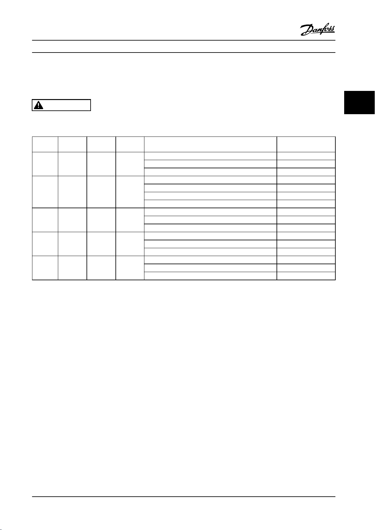
Safe Torque O Technical Data
The following values are associated to the dierent types
of safety levels:
Reaction time for T37
Maximum reaction time: 10 ms
•
Reaction time = delay between de-energizing the STO
input and switching o the frequency converter output
bridge.
Data for EN ISO 13849-1
Performance Level "d"
•
MTTFd (Mean Time To Dangerous Failure): 24816
•
years
DC (Diagnostic Coverage): 99%
•
Category 3
•
Lifetime 20 years
•
Data for EN IEC 62061, EN IEC 61508, EN IEC 61800-5-2
SIL 2 Capability, SILCL 2
•
PFH (Probability of Dangerous failure per
•
Hour)=7e-10FIT=7e-19/h
SFF (Safe Failure Fraction) >99%
•
HFT (Hardware Fault Tolerance)=0 (1001
•
architecture)
Lifetime 20 years
•
Data for EN IEC 61508 low demand
PFDavg for one-year proof test: 3, 07E-14
•
PFDavg for three year proof tests: 9, 20E-14
•
PFDavg for
•
No maintenance of the STO functionality is needed.
Take the necessary security measures, e.g. installation in a
closed cabinet that is only accessible for skilled personnel.
SISTEMA Data
Functional safety data is available via a data library for use
with the SISTEMA calculation tool from the IFA (Institute
for Occupational Safety and Health of the German Social
Accident Insurance), and data for manual calculation. The
library is permanently completed and extended.
ve year proof tests: 1, 53E-13
Abbrev. Ref. Description
Cat. EN 954-1 Category, level “B, 1-4”
FIT Failure In Time: 1E-9 hours
HFT IEC 61508 Hardware Fault Tolerance: HFT = n
means, that n+1 faults could cause a
loss of the safety function
MTTFd EN ISO
13849-1
PFH IEC 61508 Probability of Dangerous Failures per
PL EN ISO
13849-1
SFF IEC 61508 Safe Failure Fraction [%]; Percentage part
SIL IEC 61508 Safety Integrity Level
STO EN
61800-5-2
SS1 EN 61800
-5-2
Table 2.1 Abbreviations Related to Functional Safety
The PFD
Failure probability in the event of a request of the safety
function.
value (Probability of Failure on Demand)
avg
Mean Time To Failure - dangerous. Unit:
years
Hour. Consider the PFH value when the
safety device is operated in high
demand (more often than once per
year); or operated in continuous mode,
where the frequency of demands for
operation made on a safety-related
system is greater than one per year.
Discrete level used to specify the ability
of safety-related parts of control systems
to perform a safety function under
foreseeable conditions. Levels a-e.
of safe failures and dangerous detected
failures of a safety function or a
subsystem related to all failures.
Safe Torque O
Safe Torque O 1
2.2.1 Terminal 37 Safe Torque O Function
The frequency converter is available with Safe Torque O
functionality via control terminal 37. Safe Torque O
disables the control voltage of the power semiconductors
of the frequency converter output stage. This in turn
prevents generating the voltage required to rotate the
motor. When the Safe Torque O (T37) is activated, the
frequency converter issues an alarm, trips the unit, and
coasts the motor to a stop. Manual restart is required. The
Safe Torque O function can be used as an emergency
stop for the frequency converter. In normal operating
mode when Safe Torque O is not required, use the
regular stop function instead. When automatic restart is
used, ensure the requirements of ISO 12100-2 paragraph
5.3.2.5 are fullled.
8 Danfoss A/S © Rev. 2013-07-03 All rights reserved. MG34M422
Page 11

Safety Instructions and Gen... Operating Instructions
Liability Conditions
Ensure that qualied personnel installs and operates the
Safe Torque O function:
Read and understand the safety regulations
•
concerning health and safety/accident prevention
Understand the generic and safety guidelines
•
given in this description and the extended
description in the relevant Design Guide
Have a good knowledge of the generic and safety
•
standards applicable to the specic application
User is dened as:
integrator
•
operator
•
service technician
•
maintenance technician
•
Standards
Use of Safe Torque
all provisions for safety, including relevant laws, regulations
and guidelines. The optional Safe Torque O function
complies with the following standards.
IEC 60204-1: 2005 category 0 – uncontrolled stop
•
IEC 61508: 1998 SIL2
•
IEC 61800-5-2: 2007 – safe torque
•
function
IEC 62061: 2005 SIL CL2
•
ISO 13849-1: 2006 Category 3 PL d
•
ISO 14118: 2000 (EN 1037) – prevention of
•
unexpected startup
The information and instructions of the instruction manual
are not sucient for a proper and safe use of the Safe
Torque O functionality. The related information and
instructions of the relevant Design Guide must be followed.
Protective Measures
Qualied and skilled personnel are required for
•
installation and commissioning of safety
engineering systems
The unit must be installed in an IP54 cabinet or
•
in an equivalent environment. In special
applications, a higher IP degree is required
The cable between terminal 37 and the external
•
safety device must be short circuit protected
according to ISO 13849-2 table D.4
When external forces inuence the motor axis (for
•
example, suspended loads), more measures are
O on terminal 37 requires fullling of
o (STO)
required (for example, a safety holding brake) to
eliminate potential hazards
Safe Torque O Installation and Set-Up
WARNING
SAFE TORQUE OFF FUNCTION!
The Safe Torque O function does NOT isolate mains
voltage to the frequency converter or auxiliary circuits.
Perform work on electrical parts of the frequency
converter or the motor only after isolating the mains
voltage supply and waiting the length of time specied
in chapter 2.1 Safety and Warnings. Failure to isolate the
mains voltage supply from the unit and waiting the time
specied could result in death or serious injury.
It is not recommended to stop the frequency
•
converter by using the Safe Torque O function.
If a running frequency converter is stopped by
using the function, the unit trips and stops by
coasting. If unacceptable or dangerous, use
another stop mode to stop the frequency
converter and machinery, before using this
function. Depending on the application, a
mechanical brake can be required.
For synchronous and permanent magnet motor
•
frequency converters, in a multiple IGBT power
semiconductor failure: In spite of the activation of
the Safe Torque
produce an alignment torque which maximally
rotates the motor shaft by 180/p degrees. p
denotes the pole pair number.
This function is suitable for performing
•
mechanical work on the system or aected area
of a machine only. It does not provide electrical
safety. Do not use this function as a control for
starting and/or stopping the frequency converter.
To perform a safe installation of the frequency converter,
follow these steps:
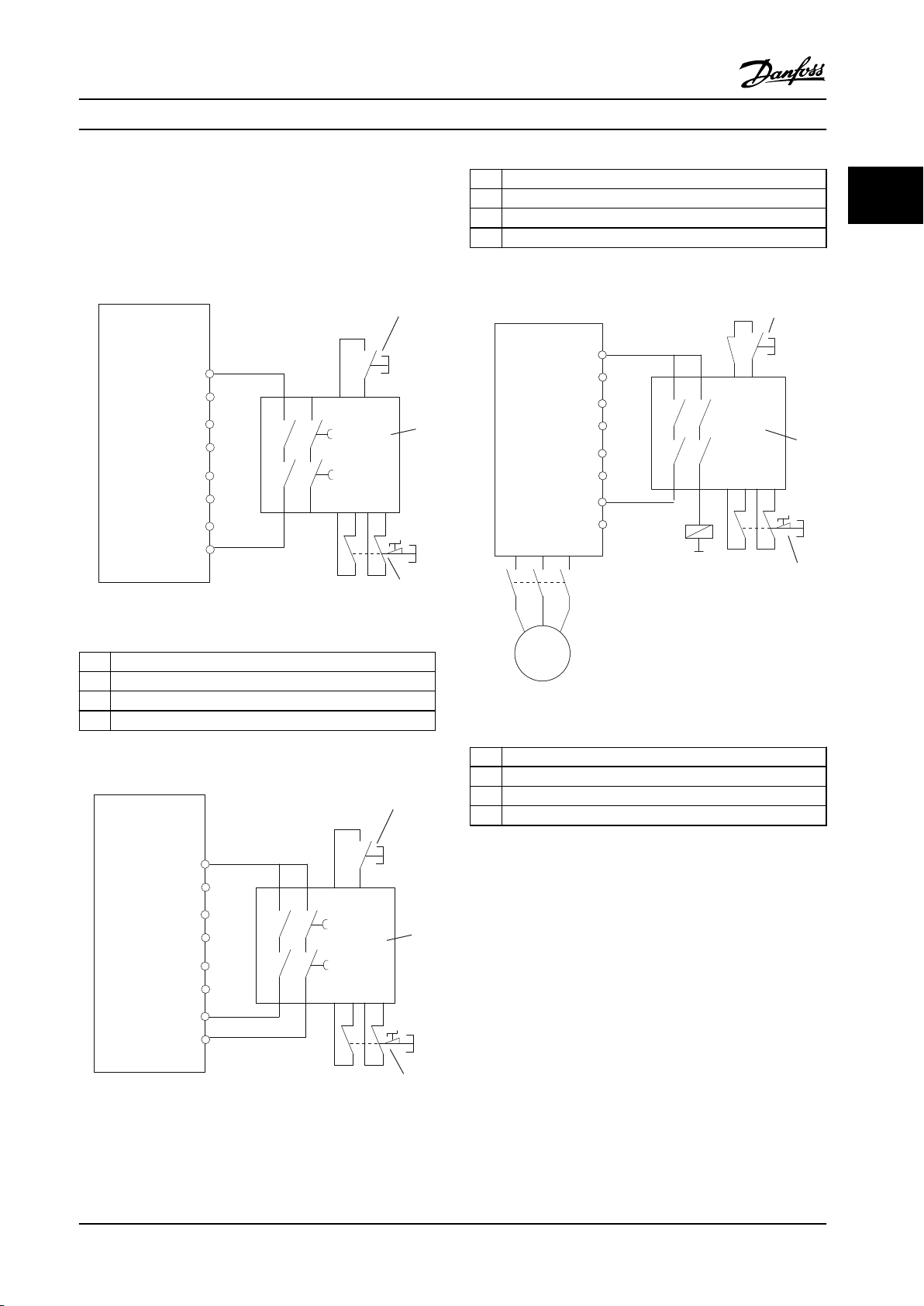
1. Remove the jumper wire between control
terminals 37 and 12 or 13. Cutting or breaking
the jumper is not sucient to avoid shortcircuiting. (See jumper on Figure 2.2.)
2. Connect an external Safety monitoring relay via a
NO safety function to terminal 37 (Safe Torque
O) and either terminal 12 or 13 (24 V DC).
Follow the instruction for the safety device. The
Safety monitoring relay must comply with
Category 3 /PL “d” (ISO 13849-1) or SIL 2 (EN
62061).
O function, the system can
2 2
MG34M422 Danfoss A/S © Rev. 2013-07-03 All rights reserved. 9
Page 12
12/13
37
130BA874.10
130BC971.10
12
2
4
1
5
3
37
Safety Instructions and Gen...
22
VLT® Compressor Drives CDS 302/CDS 303
O. Moreover, perform the test after each modication of
the installation.
Example with STO
A safety relay evaluates the E-Stop button signals and
triggers an STO function on the frequency converter in the
event of an activation of the E-Stop button (See Figure 2.4).
This safety function corresponds to a category 0 stop
(uncontrolled stop) in accordance with IEC 60204-1. If the
function is triggered during operation, the motor runs
down in an uncontrolled manner. The power to the motor
is safely removed, so that no further movement is possible.
It is not necessary to monitor plant at a standstill. If an
external force eect can occur, provide additional measures
to prevent any potential movement (for example
mechanical brakes).
NOTICE!
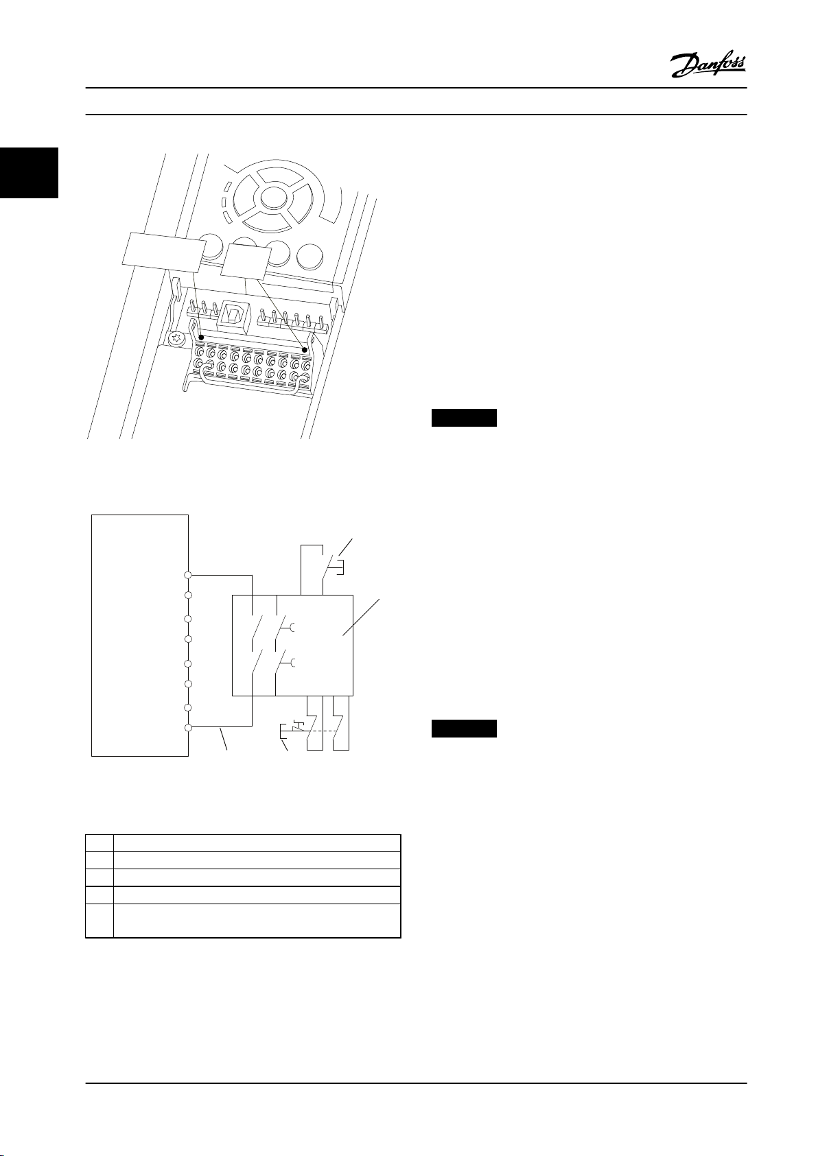
Figure 2.2 Jumper between Terminal 12/13 (24 V) and 37
For all applications with Safe Torque O it is important
that short circuit in the wiring to T37 can be excluded.
Exclude the short circuit as described in EN ISO 13849-2
D4 by the use of protected wiring (shielded or
segregated).
Figure 2.3 Installation to Achieve a Stopping Category 0 (EN
60204-1) with Cat. 3 /PL “d” (ISO 13849-1) or SIL 2 (EN 62061).
1 Frequency converter
2 [Reset] key
3 Safety relay (cat. 3, PL d or SIL2
4 Emergency stop button
5 Short-circuit protected cable (if not inside installation IP54
cabinet)
Table 2.2 Legend to Figure 2.3
Safe Torque O Commissioning Test
After installation and before rst operation, perform a
commissioning test of the installation using Safe Torque
Example with SS1
SS1 corresponds to a controlled stop, stop category 1
according to IEC 60204-1 (see Figure 2.5). When activating
the safety function, the frequency converter performs a
normal controlled stop. This can be activated through
terminal 27. After the safe delay time has expired on the
external safety module, the STO will be triggered and
terminal 37 will be set low. Ramping down as congured
in the frequency converter. If the frequency converter is
not stopped after the safe delay time, the activation of STO
will coast the frequency converter.
NOTICE!
When using the SS1 function, the brake ramp of the
frequency converter is not monitored with respect to
safety.
Example with Category 4/PL e application
Where the safety control system design requires two
channels for the STO function to achieve Category 4/PL e,
implement one channel via Safe Torque O T37 (STO) and
the other by a contactor. Connect the contactor in either
the frequency converter input or output power circuits and
controlled by the Safety relay (see Figure 2.6). The
contactor must be monitored through an auxiliary guided
contact, and connected to the reset input of the Safety
Relay.
Paralleling of Safe Torque O input the one Safety Relay
Safe Torque O inputs T37 (STO) may be connected
directly if it is required to control multiple frequency
converters from the same control line via one Safety Relay
10 Danfoss A/S © Rev. 2013-07-03 All rights reserved. MG34M422
Page 13
130BC972.10
12
37
1
3
4
2
130BC973.10
18
37
4
1
2
12
3
130BC974.10
12
37
K 1
K 1
K 1
4
1
3
2
Safety Instructions and Gen... Operating Instructions
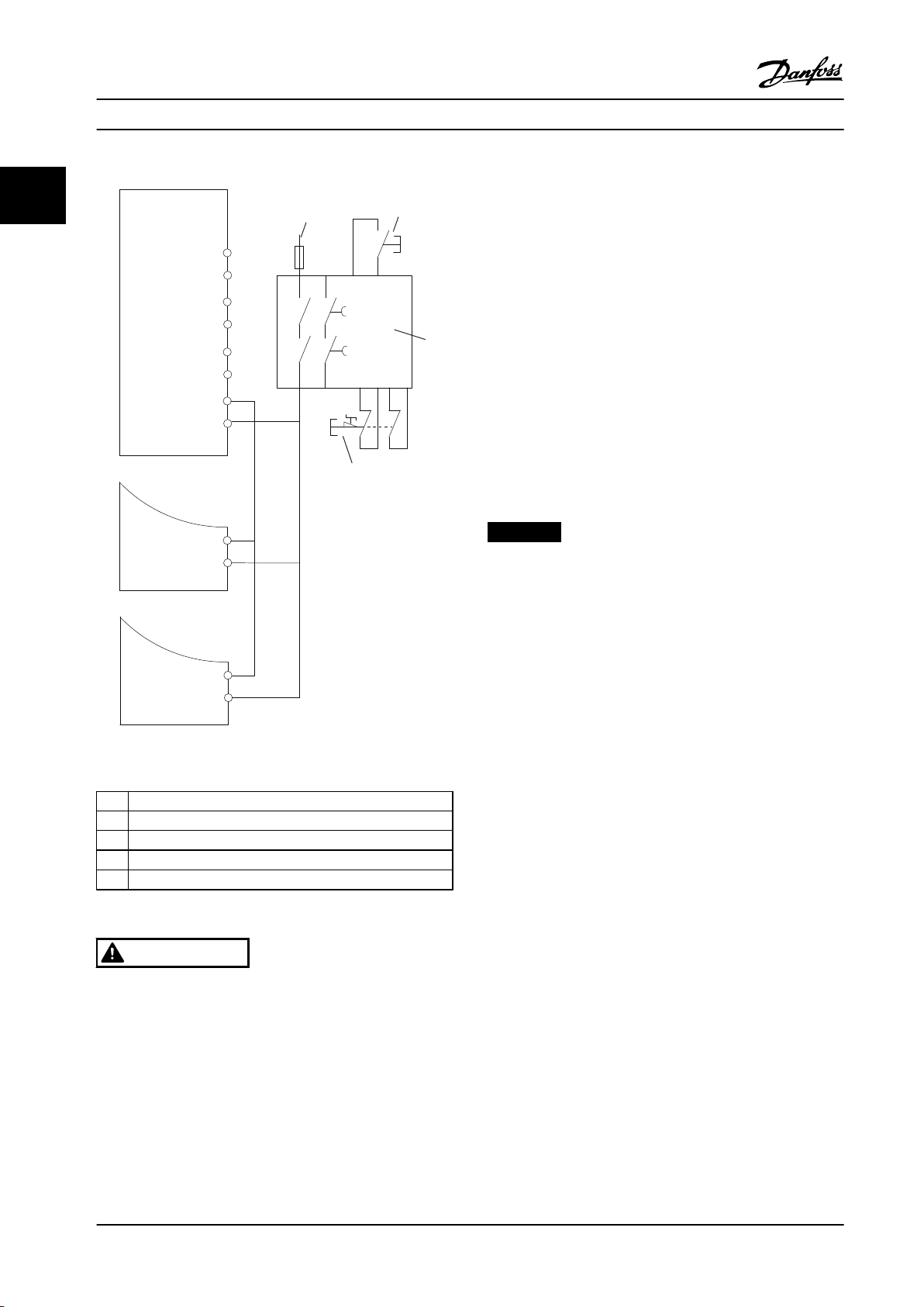
(see Figure 2.7). Connecting inputs increases the probability
of a fault in the unsafe direction. A fault in one frequency
converter can result in all frequency converters becoming
enabled. The probability of a fault for T37 is so low, that
the resulting probability still meets the requirements for
SIL2.
Figure 2.4 STO Example
1 Frequency converter
2 [Reset] key
3 Safety relay
4 Emergency stop
Table 2.4 Legend to Figure 2.5
2 2
1 Frequency converter
2 [Reset] key
3 Safety relay
Figure 2.6 STO Category 4 Example
4 Emergency stop
Table 2.3 Legend to Figure 2.4
1 Frequency converter
2 [Reset] key
3 Safety relay
4 Emergency stop
Table 2.5 Legend to Figure 2.6
Figure 2.5 SS1 Example
MG34M422 Danfoss A/S © Rev. 2013-07-03 All rights reserved. 11
Page 14
130BC975.10
12
37
1
20
1
1
3
4
5
2
37
20
37
20
Safety Instructions and Gen...
VLT® Compressor Drives CDS 302/CDS 303
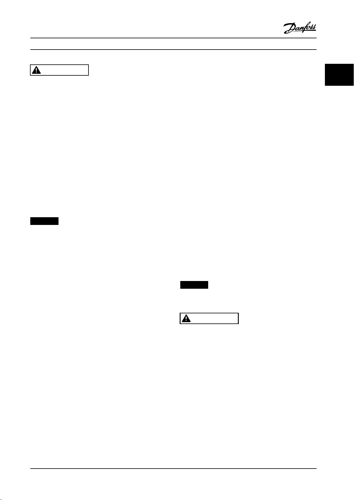
1. Activate the Safe Torque O function by
22
removing the 24 V DC voltage supply to the
terminal 37.
2. After activation of Safe Torque O (that is, after
the response time), the frequency converter
coasts (stops creating a rotational eld in the
motor). The response time is typically less than 10
ms.
The frequency converter is guaranteed not to restart
creation of a rotational eld by an internal fault (in
accordance with Cat. 3 of EN 954-1, PL d acc. EN ISO
13849-1 and SIL 2 acc. EN 62061). After activation of Safe
Torque O, the display shows the text ”Safe Stop
activated”. The associated help text says, "Safe Stop has
been activated. This means that the Safe Torque O has
been activated, or that normal operation has not been
resumed yet after Safe Torque O activation”.
NOTICE!
The requirements of Cat. 3 (EN 954-1)/PL “d” (ISO
13849-1) are only fullled while 24 V DC supply to
terminal 37 is kept removed or low by a safety device
which itself fullls Cat. 3 (EN 954-1) PL “d” (ISO 13849-1).
If external forces act on the motor, it must not operate
without additional measures for fall protection. External
forces can arise for example, in the event of vertical axis
(suspended loads) where an unwanted movement, for
example caused by gravity, could cause a hazard. Fall
protection measures can be additional mechanical
Figure 2.7 Paralleling of Multiple Drives Example
1 Frequency converter
2 24 V DC
3 [Reset] key
4 Safety relay
5 Emergency stop
Table 2.6 Legend to Figure 2.7
brakes.
By default the Safe Torque O function is set to an
Unintended Restart Prevention behaviour. Therefore, to
resume operation after activation of Safe Torque O,
1. reapply 24 V DC voltage to terminal 37 (text Safe
Torque O activated is still displayed)
2. create a reset signal (via bus, Digital I/O, or
[Reset] key.
WARNING
Safe Torque O activation (that is removal of 24 V DC
voltage supply to terminal 37) does not provide electrical
safety. The Safe Torque O function itself is therefore not
sucient to implement the Emergency-O function as
dened by EN 60204-1. Emergency-O requires measures
The Safe Torque O function can be set to an Automatic
Restart behaviour. Set the value of parameter 5-19 Terminal
37 Safe Stop from default value [1] to value [3].
Automatic Restart means that Safe Torque O is
terminated, and normal operation is resumed, as soon as
the 24 V DC are applied to Terminal 37. No Reset signal is
required.
of electrical isolation, for example, by switching o
mains via an additional contactor.
12 Danfoss A/S © Rev. 2013-07-03 All rights reserved. MG34M422
Page 15
Safety Instructions and Gen... Operating Instructions
WARNING
Automatic Restart Behaviour is permitted in one of the
two situations:
1. The Unintended Restart Prevention is
implemented by other parts of the Safe Torque
O installation.
2. A presence in the dangerous zone can be
physically excluded when Safe Torque O is not
activated. In particular, paragraph 5.3.2.5 of ISO
12100-2 2003 must be observed
2.2.2 Safe Torque O Commissioning Test
After installation and before rst operation, perform a
commissioning test of an installation or application, using
Safe Torque O.
Perform the test again after each modication of the
installation or application involving the Safe Torque O.
NOTICE!
A passed commissioning test is mandatory after rst
installation and after each change to the safety installation.
The commissioning test (select one of cases 1 or 2 as
applicable):
Case 1: Restart prevention for Safe Torque O is
required (that is Safe Torque O only where
parameter 5-19 Terminal 37 Safe Stop is set to default
value [1], or combined Safe Torque O and MCB 112
where parameter 5-19 Terminal 37 Safe Stop is set to [6]
PTC 1 & Relay A or [9] PTC 1 & Relay W/A):
1.1 Remove the 24 V DC voltage supply to
terminal 37 using the interrupt device while the
frequency converter drives the motor (that is
mains supply is not interrupted). The test step is
passed when
the motor reacts with a coast, and
•
the mechanical brake is activated (if
•
connected)
the alarm “Safe Torque O [A68]” is
•
displayed in the LCP, if mounted
1.2 Send Reset signal (via Bus, Digital I/O, or
[Reset] key). The test step is passed if the motor
remains in the Safe Torque O state, and the
mechanical brake (if connected) remains
activated.
1.3 Reapply 24 V DC to terminal 37. The test step
is passed if the motor remains in the coasted
state, and the mechanical brake (if connected)
remains activated.
1.4 Send Reset signal (via Bus, Digital I/O, or
[Reset] key). The test step is passed when the
motor becomes operational again.
The commissioning test is passed if all four test steps 1.1,
1.2, 1.3 and 1.4 are passed.
Case 2: Automatic Restart of Safe Torque O is wanted
and allowed (that is, Safe Torque O only where
parameter 5-19 Terminal 37 Safe Stop is set to [3], or
combined Safe Stop and MCB 112 where
parameter 5-19 Terminal 37 Safe Stop is set to [7] PTC 1 &
Relay W or [8] PTC 1 & Relay A/W):
2.1 Remove the 24 V DC voltage supply to
terminal 37 by the interrupt device while the
frequency converter drives the motor (that is
mains supply is not interrupted). The test step is
passed when
the motor reacts with a coast, and
•
the mechanical brake is activated (if
•
connected)
the alarm “Safe Stop [A68]” is displayed
•
in the LCP, if mounted
2.2 Reapply 24 V DC to terminal 37.
If the motor becomes operational again, The test step is
passed. If both test steps 2.1 and 2.2 are passed, the
commissioning test is passed.
NOTICE!
See warning on the restart behaviour in
chapter 2.2.1 Terminal 37 Safe Torque O Function
WARNING
The Safe Torque O function can be used for
asynchronous, synchronous and permanent magnet
motors. Two faults can occur in the power semiconductor
of the frequency converter. When using synchronous or
permanent magnet motors a residual rotation can result
from the faults. The rotation can be calculated to Angle
= 360/(Number of Poles). The application using
synchronous or permanent magnet motors must take
this residual rotation into consideration and ensure that
it does not pose a safety risk. This situation is not
relevant for asynchronous motors.
2 2
MG34M422 Danfoss A/S © Rev. 2013-07-03 All rights reserved. 13
Page 16

130BT330.10
61
68
39
42
50
53
54
RELAY 1
RELAY 2
03
02
01
06
05
04
130BT346.10
WARNING:
Risk of Electric Shock - Dual supply
Discunnect mains and loadsharing before service
61
68
39
50
53
54
5
42
03
02
01
06
05
04
99
95
130BT347.10
WARNING:
Risk of Electric Shock - Dual supply
Disconnect mains and loadsharing before service
How to Install
3 How to Install
VLT® Compressor Drives CDS 302/CDS 303
33
3.1 Environment
3.1.1 Ambient Temperature and Altitude
The normal ambient temperature supported by the CDS is
Mechanical Installation
3.2
3.2.1 Accessory Bags
Find the following parts included in the accessory bag:
-14000000 °F to +122 °F without derating. The CDS
operates normally down to -4 °F with only the LCP display
function impaired but without performance reduction.
For ambient temperatures above +122 °F, it is mandatory
to integrate the derating output factor for the maximum
compressor electrical motor power/current.
For altitudes above 3280 ft (1000 m), apply derating as
shown in Table 3.1.
For more details on derating due to environmental factors,
Figure 3.1 Enclosures B1 and B2, IP21/IP55/Type 1/Type 12
contact Danfoss technical support.
Altitude [ft/m] Derating factor
3280/1000 1
4921/1500 0.95
6561/2000 0.90
8202/2500 0.86
9842/3000 0.82
11482/3500 0.78
Table 3.1 Altitude Derating Factor
Figure 3.2 Enclosure B3, IP20/Chassis
3.1.2 Environmental Requirements for
Mechanical Installation
The unit is air-cooled. To protect the unit from overheating,
ensure that the ambient temperature does not exceed the
maximum temperature stated for the 24-hour average
temperature. If the ambient temperature is in the range of
113 °F to 131 °F, derating becomes relevant. If derating for
ambient temperature is not taken into account, the service
life of the unit is reduced.
14 Danfoss A/S © Rev. 2013-07-03 All rights reserved. MG34M422
Figure 3.3 Enclosure B4, IP20/Chassis
Page 17

130BA406.10
61 68 6
39 42 50 53 54 5
03 02 01
06 05 04
A
B
C D
E
F
G
H
I
J K
WARNING:
Risk of Electric Shock - Dual supply
Disconnect mains and loadsharing before service
ISOA0021
99
95
61
68
39
50
53
54
5
42
03
02
01
06
05
04
130BT348.10
Risk of Electric Shock - Dual supply
Disconnect mains and loadsharing before service
WARNING:
RELAY 1
RELAY 2
a
b
130BA419.10
How to Install Operating Instructions
Figure 3.4 Enclosures C1 and C2, IP55/66/Type 1/Type 12
Figure 3.5 Enclosure C3, IP20/Chassis
3 3
3.2.2 Mechanical Mounting
1. Drill holes in accordance with the measurements
given.
2. Provide screws suitable for the surface on which
the compressor drive should be mounted.
3. Retighten all four screws.
The frequency converter IP20 allows side-by-side installation. Because of the need for cooling, there must be a
minimum of 7.9 in (200 mm) free air passage above and
below the frequency converter.
The back wall must always be solid. All frequency
converters are equipped with a back metal plate to
guarantee proper heat exchanger ventilation. Never
remove this metal sheet.
Figure 3.6 Clearance
Frame size
A1*/A2/A3/A4/A5
/B1
B2/B3/B4/C
1/C3
C2/C4
a [Inch/mm] 3.3/100 7.9/200 8.9/225
b [inch/mm] 3.3/100 7.9/200 8.9/225
Table 3.2 Air Passage for Dierent Frame Sizes
MG34M422 Danfoss A/S © Rev. 2013-07-03 All rights reserved. 15
Page 18
130BA219.11
1
130BA228.11
1
How to Install
VLT® Compressor Drives CDS 302/CDS 303
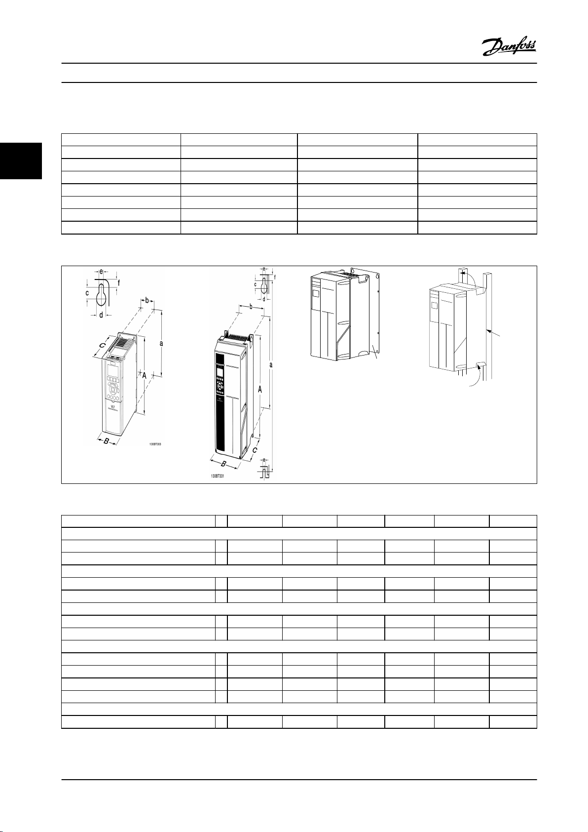
3.2.3 Mechanical Dimensions
IP 20 Chassis T2 [240 V] T4 [480 V] T6 [575 V]
VSH088 [15 kW] B4 B3 B3
33
VSH117 [18 kW] C3 B4 B4
VSH170 [22 kW] C3 B4 B4
IP 55 NEMA 12
VSH088 [15 kW] C1 B1 B1
VSH117 [18 kW] C1 B2 B2
VSH170 [22 kW] C1 B2 B2
Table 3.3 Related VSH Numbers
Table 3.4 Dimensional Drawings
B1 B2 B3 B4 C1 C3
Height [inch/mm]
Backplate A 18.90/480 25.59/650 15.71/399 20.47/520 26.77/680 21.65/550
Distance between mounting holes a 17.87//454 24.57/624 14.96/380 19.49/495 25.51/648 20.51/521
Width [inch/mm]
Back plate B 9.53/242 9.53/242 6.50/165 9.06/230 12.13/308 12.13/308
Distance between mounting holes b 8.28/210 8.28/210 5.51/140 7.87/200 10.71/272 10.63/270
Depth [inch/mm]
Without option C 10.24/260 10.24/260 9.80/249 9.53/242 12.21/310 13.11/333
With option C 10.24/260 10.24/260 10.24/260 9.53/242 12.21/310 13.11/333
Screw holes [inch/mm]
c 0.47/12.0 0.47/12.0 0.32 0.49/12.0
d Ø 0.75/19.0 Ø 0.75/19.0 0.47/12.0 Ø 0.75/19.0
e Ø 0.35/9 Ø 0.35/9 0.34/8.8 0.33/8.5 Ø 0.35/9 0.33/8.5
f 0.35/9 0.35/9 0.31/7.9 0.59/15 0.38/9.8 0.67/17
Other Specications
Max. weight [lbs/kg] 50.4/23 59.53/27 26.46/12 51.81/23.5 99.21/45 77.16/35
Table 3.5 Mechanical Dimensions
16 Danfoss A/S © Rev. 2013-07-03 All rights reserved. MG34M422
Page 19
How to Install Operating Instructions
3.3 Electrical Installation
3.3.1 Cables General
CAUTION
Cables general:
Always comply with national and local regulations on cable cross-sections.
Frame
size
B1 5.5-7.5 11-15 15
B2 11 18.5-22 18.5-22
B3 5.5-7.5 11-15 15
B4 11-15 18.5-30 18.5-22
C3 18.5-22 - -
200-240 V
[kW]
380-500 V
[kW]
525-690 V
[kW]
Cable for Tightening torque
Mains, motor cables 1.8
Relay 0.5-0.6
Ground 2-3
Mains 4.5
Motor cables 4.5
Relay 0.5-0.6
Ground 2-3
Mains, motor cables 1.8
Relay 0.5-0.6
Ground 2-3
Mains, motor cables 4.5
Relay 0.5-0.6
Ground 2-3
Mains, motor cables 10
Relay 0.5-0.6
Ground 2-3
3 3
[Nm]
Table 3.6 Tightening Torque
3.3.2 Removal of Knockouts for Extra Cables
Remove cable entry from the frequency converter (avoiding foreign parts in the frequency converter when
•
removing knockouts)
Support cable entry around the knockout that should be removed
•
The knockout can now be removed with a strong mandrel and a hammer
•
Remove burrs from the hole
•
Mount cable entry on frequency converter
•
MG34M422 Danfoss A/S © Rev. 2013-07-03 All rights reserved. 17
Page 20
130BT332.10
130BA720.10
How to Install
VLT® Compressor Drives CDS 302/CDS 303
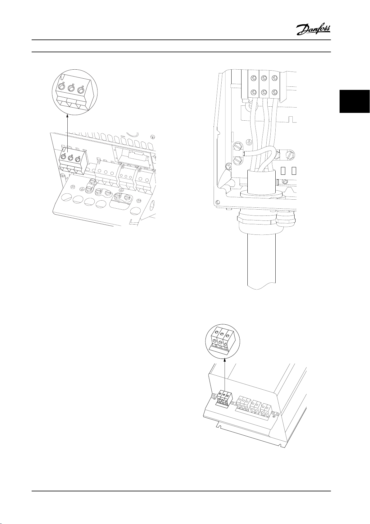
3.3.3 Mains Connection for B1, B2 and B3
NOTICE!
33
Frequency converter sizes dier, but terminal numbers
are always the same. Incoming power is always 91, 92,
93 labeled L1, L2, L3.
NOTICE!
For correct cable dimensions see chapter 8 General
Specications.
Figure 3.9 How to Connect to Mains and Grounding for B3
with RFI
Figure 3.7 How to Connect to Mains and Grounding for B1
and B2
Figure 3.8 How to Connect to Mains and Grounding for B3
without RFI
3.3.4 Mains connection for B4, C1 and C3
NOTICE!
Frequency converter sizes dier but terminal numbers
are always the same. Incoming power is always 91, 92,
93 labeled L1, L2, L3.
18 Danfoss A/S © Rev. 2013-07-03 All rights reserved. MG34M422
Page 21
L1 91
L2 92
L3 93
L1 91
L2 92
L3 93
U 96
V 97
W 98
DC-88
DC+89
R-81
R+82
130BA714.10
95
99
130BA389.10
95
91
L1
92
L2
93
L3
91 92 93
91 92 93
96 97 98
88 89
81 82
99
95
130BA718.10
How to Install Operating Instructions
3 3
Figure 3.10 How to Connect to Mains and Grounding for B4
Figure 3.11 How to Connect to Mains and Grounding for C1
and C2
Figure 3.12 How to Connect C3 to Mains and Grounding
MG34M422 Danfoss A/S © Rev. 2013-07-03 All rights reserved. 19
Page 22
130BC399.10
130BT333.10
L 1
L 2
L 3
91
92
93
130BT336.10
How to Install
VLT® Compressor Drives CDS 302/CDS 303
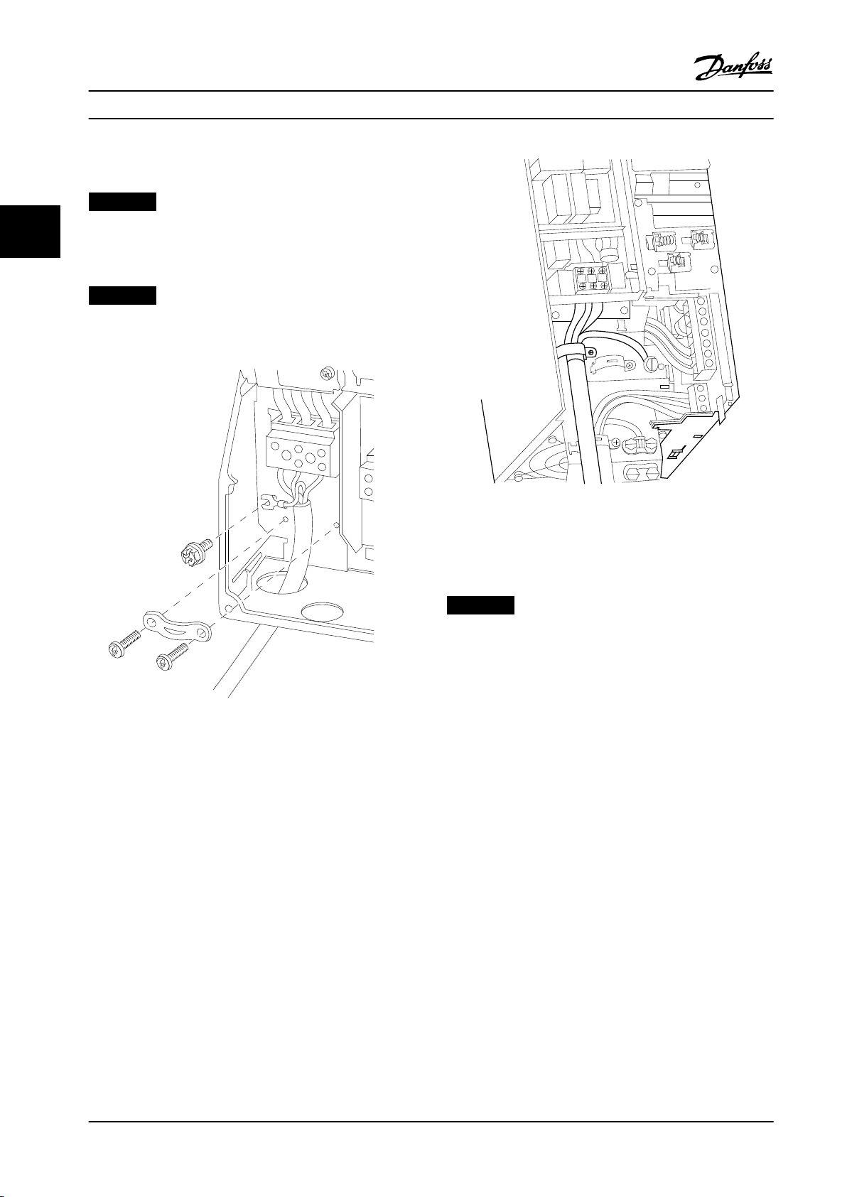
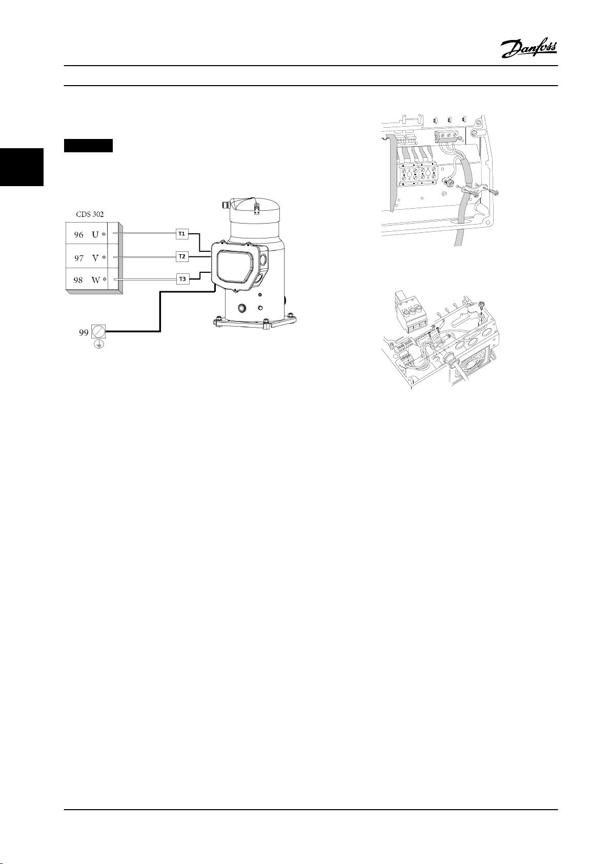
3.3.5 Motor Compressor Connection
NOTICE!
33
Always wire terminal 96 (U) to T1, 97 (V) to T2, and 98
(W) to T3.
Figure 3.14 How to Connect to Motor Terminals B1/B2
Figure 3.13 Motor/Compressor Wiring
Motor compressor cable must be screened/armored. If an
unscreened/unarmored cable is used, some EMC
requirements are out of compliance. For more information,
see EMC specications.
1. Fasten decoupling plate to the bottom of the
frequency converter with screws and washers
from the accessory bag.
2. Attach motor compressor cable to terminals 96
(U), 97 (V), 98 (W).
3. Connect to ground connection (terminal 99) on
decoupling plate with screws from the accessory
bag.
4. Insert terminals 96 (U), 97 (V), 98 (W) and motor
compressor cable to terminals labeled MOTOR.
5. Fasten screened cable to decoupling plate with
screws and washers from the accessory bag.
6. Connect U, V, W for motor compressor clockwise.
Figure 3.15 How to Connect to Mains and Ground without
Mains Disconnect
3.3.6 Motor Compressors Cables
Correct dimensioning of motor compressor cable crosssection and length is described in the application manual.
Use a screened/armored motor compressor cable
•
to comply with EMC emission specications
Keep the motor compressor cable as short as
•
possible to reduce the noise level and leakage
currents
Connect the motor compressor cable screen to
•
both the decoupling plate of the frequency
converters and to the metal cabinet of the motor
compressor
Make the screen connections with the largest
•
possible surface area (cable clamp). Use the
supplied installation devices in the frequency
converter for making the screen connections.
20 Danfoss A/S © Rev. 2013-07-03 All rights reserved. MG34M422
Page 23

130BT248.10
130BT334.10
How to Install Operating Instructions
3.3.7 Electrical Installation of Motor
Compressor Cables
Screening of cables
Avoid installation with twisted screen ends (pigtails). They
reduce the screening eect at higher frequencies.
Cable length and cross section
The frequency converter has been tested with a given
length of cable and a given cross section of that cable. If
the cross section is increased, the cable capacitance - and
thus the leakage current - may increase, and the cable
length must be reduced correspondingly.
Aluminum conductors
Aluminium conductors are not recommended. Terminals
accept aluminium conductors, but clean the conductor
surface and remove and seal the oxidation by neutral acidfree Vaseline grease before the conductor is connected.
Furthermore, the terminal screw must be retightened after
two days due to the softness of the aluminium. It is crucial
to keep the connection a gas tight joint, otherwise the
aluminium surface oxidizes again.
3.3.9 Access to Control Terminals
3 3
Figure 3.16 B3, B4 and C3 Enclosures
3.3.8 Compressor Motor Protection
The frequency converter fully provides electrical
compressor motor protection.
The frequency converter makes through an
•
electronic current measurement anti-overload and
lock-rotor compressor motor protection (see
description in the application manual).
The frequency converter is protected against
•
short circuits on compressor terminals T1, T2, T3
If a mains phase is missing, the frequency
•
converter trips or issues a warning (depending on
the load)
If a compressor motor phase is missing, the
•
frequency converter trips
The frequency converter is protected against
•
ground faults on compressor motor terminals T1,
T2, T3
Figure 3.17 C1, B1 and B2 Enclosures
Control terminals are located beneath the LCP. The inside
of the removable cover shows the terminals.
MG34M422 Danfoss A/S © Rev. 2013-07-03 All rights reserved. 21
Page 24
1
4
2
3
130BA012.12
61
68
69
39
42
50
53
54
55
12
13
18
19
27
29
32
33
20
130BT312.10
130BT311.10
130BA150.10
9 - 10 mm
(0.37 in)
130BT306.10
How to Install
VLT® Compressor Drives CDS 302/CDS 303
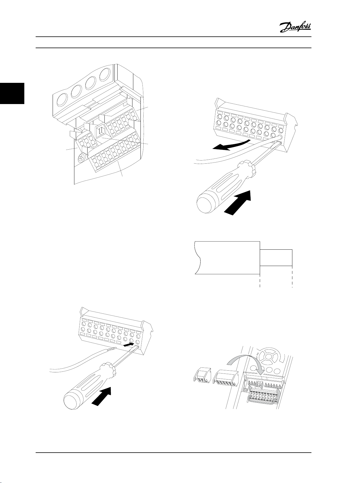
To remove the cable from the terminal:
1. Insert a screwdriver in the square hole.
33
Figure 3.18 Control Terminals
2. Pull out the cable.
1. 10 pole plug digital I/O
2. 3 pole plug RS-485 Bus
3. 6 pole analog I/O
4. USB Connection
To mount the cable to the terminal:
1. Strip isolation of 9-10 mm.
2. Insert a screwdriver in the square hole.
3. Insert the cable in the adjacent circular hole.
4. Remove the screwdriver. The cable is now
mounted to the terminal.
Figure 3.20 Removing the Cable
Figure 3.21 Stripping the Cable
3.3.10 Basic Wiring Example
1. Mount terminals from the accessory bag to the
front of the frequency converter.
Figure 3.19 Mounting the Cable
22 Danfoss A/S © Rev. 2013-07-03 All rights reserved. MG34M422
Figure 3.22 Mounting the Terminals
Page 25
How to Install Operating Instructions
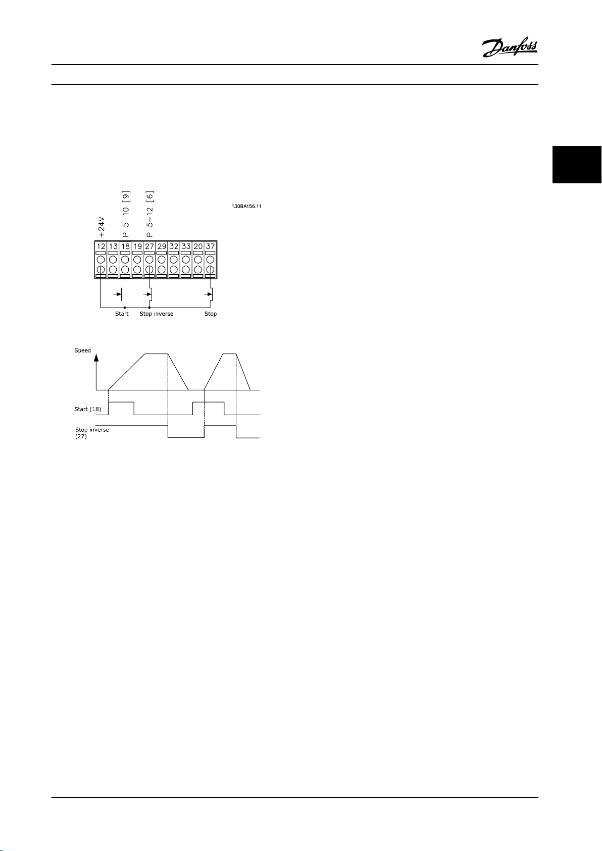
2. Connect terminals 18, 27 and 37 to +24 V
(terminal 12/13)
Default settings:
18 = start
27 = coast inverse
3 3
Figure 3.23 Example of Basic Wiring
MG34M422 Danfoss A/S © Rev. 2013-07-03 All rights reserved. 23
Page 26
How to Install
VLT® Compressor Drives CDS 302/CDS 303
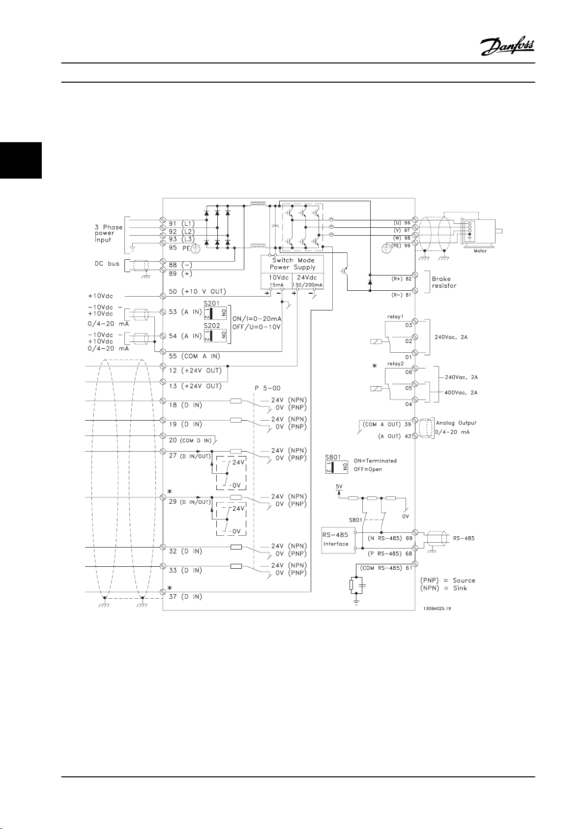
3.3.11 Electrical Installation, Control Cables
Use terminal 37 as input for safe stop. In rare cases, control cables more than 100 m (330 ft) and analog signals result in
50/60 Hz ground loops due to noise from mains supply cables. If this situation occurs, break the screen or insert a 100 nF
33
capacitor between screen and chassis. Connect the digital and analog inputs and outputs separately to the frequency
converter common inputs (terminal 20, 55, 39) to avoid ground currents aecting the system.
Figure 3.24 Electrical Diagram - Control Cables
Control cables must be shielded/armored. To connect the screen to the frequency converter decoupling plate for control
cables, use a clamp from the accessory bag.
24 Danfoss A/S © Rev. 2013-07-03 All rights reserved. MG34M422
Page 27
130BT340.11
1
2
How to Install Operating Instructions
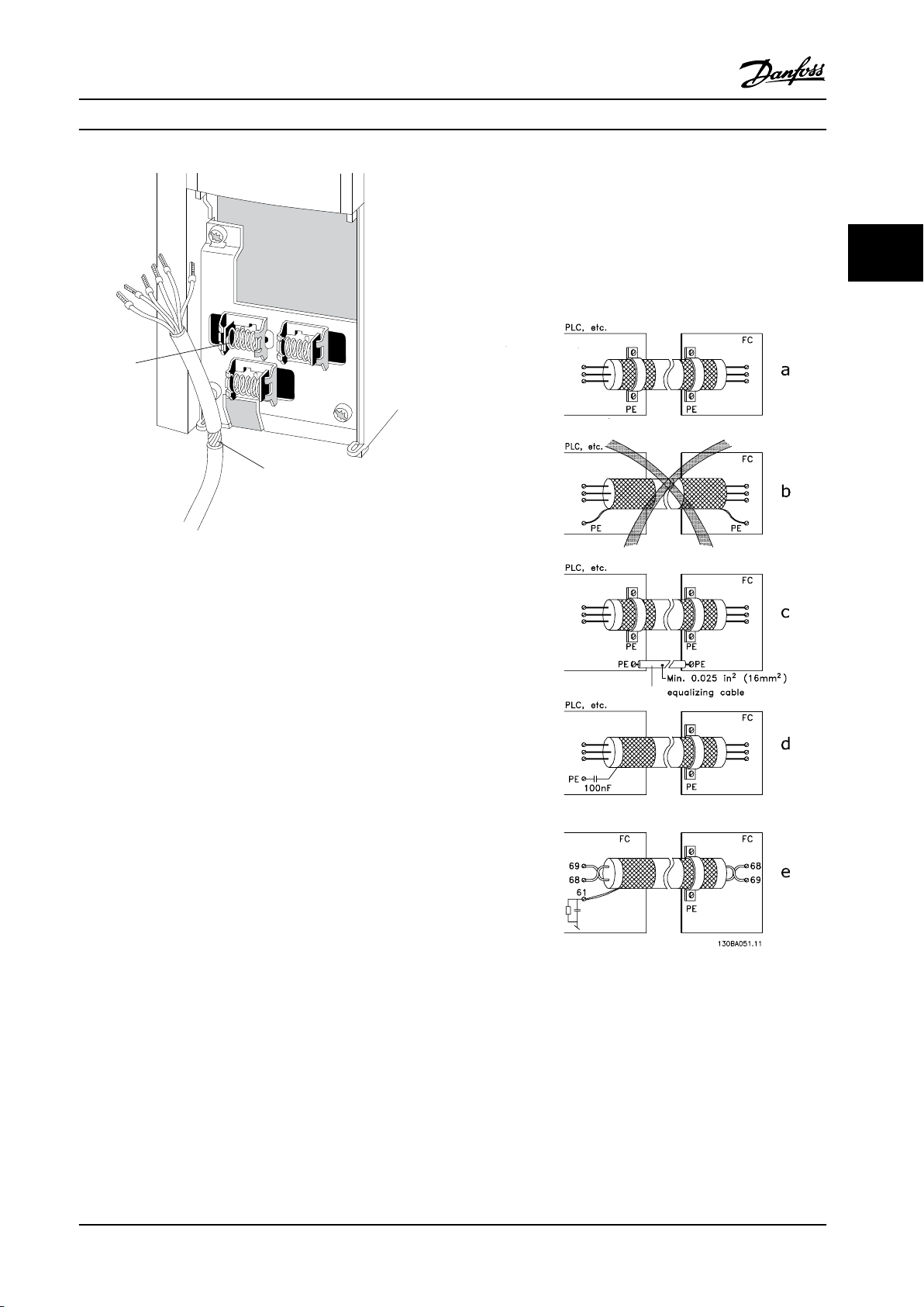
Figure 3.25 Control Cable Connection
e. Cables for serial communication
Eliminate low-frequency noise currents between two
frequency converters by connecting one end of the screen
to terminal 61. This terminal is connected to ground via an
internal RC link. To reduce the dierential mode
interference between the conductors, use twisted-pair
cables.
3 3
Figure 3.26 indicates how correct grounding is carried out
and what to do if in doubt.
a. Correct grounding
Control cables and cables for serial communication must
tted with cable clamps at both ends to ensure the
be
best possible electrical contact.
b. Wrong grounding
Do not use twisted cable ends (pigtails). They increase the
screen impedance at high frequencies.
c. Protection concerning ground potential between PLC
(Program Logic Controller) and frequency converter
If the ground potential between the frequency converter
and the PLC (etc.) is dierent, electric noise may occur that
disturbs the entire system. Solve this problem by tting an
equalizing cable, next to the control cable. Minimum cable
cross-section: 16 mm2.
d. For 50/60 Hz ground loops
If long control cables are used, 50/60 Hz ground loops may
occur. Solve this problem by connecting one end of the
screen to ground via a 100 nF capacitor (keeping leads
short).
Figure 3.26 Examples of ground Wiring
MG34M422 Danfoss A/S © Rev. 2013-07-03 All rights reserved. 25
Page 28

How to Install
VLT® Compressor Drives CDS 302/CDS 303
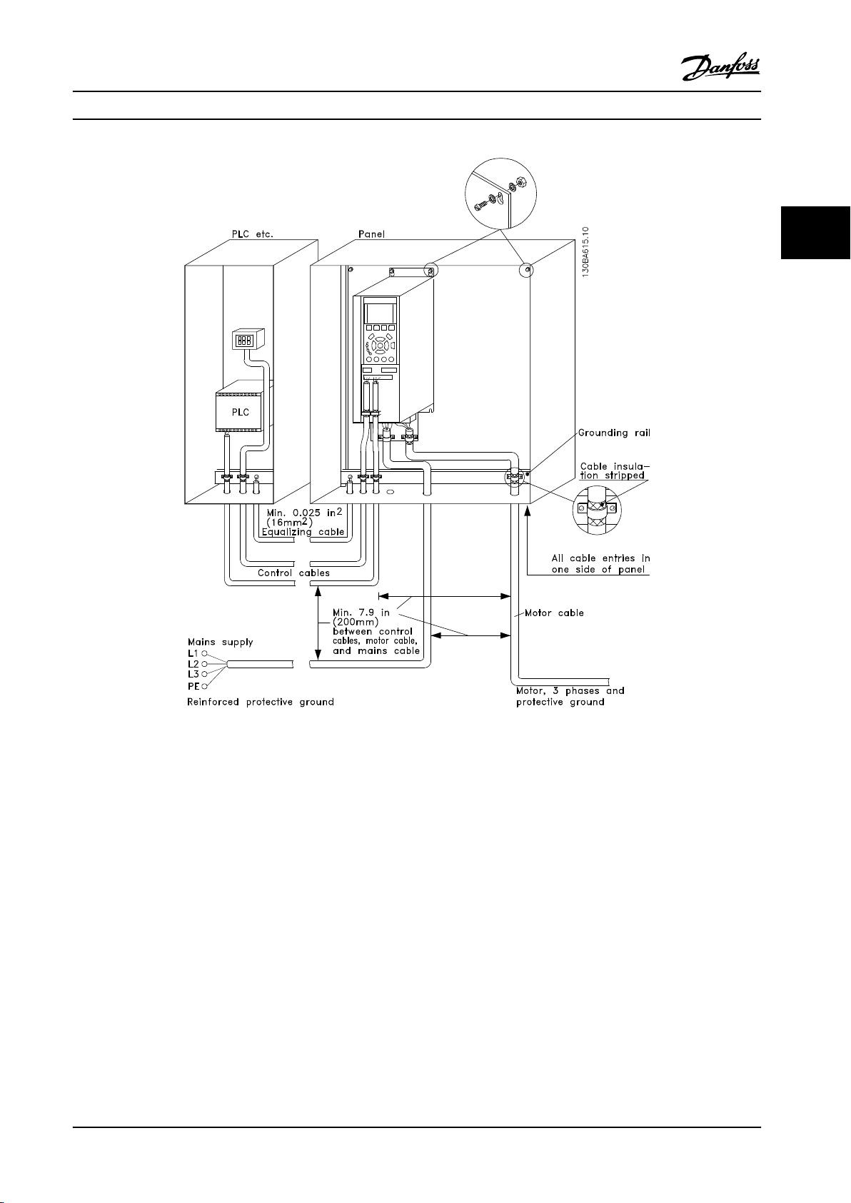
3.3.12 Electrical Installation - EMC
Protection
The following is a guideline to good engineering practice
33
when installing frequency converters. To comply with EN
61800-3 First environment, follow these guidelines. If the
installation is in EN 61800-3 Second environment, i.e.
industrial networks, or in an installation with its own
transformer, deviation from these guidelines is allowed, but
not recommended.
Good engineering practice to ensure EMC-correct
electrical installation
Use only braided screened/armored motor
•
compressor cables and braided screened/armored
control cables. The screen should provide a
minimum coverage of 80%. The screen material
must be metal, not limited to but typically
copper, aluminum, steel, or lead. There are no
special requirements for the mains cable.
Installations using rigid metal conduits are not
•
required to use screened cable, but the motor
compressor cable must be installed in conduit
separate from the control and mains cables. Full
connection of the conduit from the frequency
converter to the motor compressor is required.
The EMC performance of exible conduits varies a
lot and information from the manufacturer must
be obtained.
Leave the screen as close to the connectors as possible.
Figure 3.27 shows an example of an EMC-correct electrical
installation of an IP20 frequency converter.
The frequency converter is tted in an installation cabinet
with an output contactor and connected to a PLC, which is
installed in a separate cabinet. Other ways of doing the
installation may have just as good an EMC performance,
provided the above guide lines to engineering practice are
followed. Installing without following the guideline, and
using unscreened cables and control wires do not comply
with all emission requirements, although the immunity
requirements are
Connect the screen/armor/conduit to ground at
•
both ends for motor compressor cables as well as
for control cables. In some cases, it is not possible
to connect the screen in both ends. If so, connect
the screen at the frequency converter. See also
chapter 3.3.11 Electrical Installation, Control Cables.
Avoid terminating the screen/armor with twisted
•
ends (pigtails). It increases the high frequency
impedance of the screen, which reduces its
eectiveness at high frequencies. Use low
impedance cable clamps or EMC cable glands
instead.
Avoid using unscreened/unarmored motor
•
compressor or control cables inside cabinets
housing the frequency converter(s).
fullled.
26 Danfoss A/S © Rev. 2013-07-03 All rights reserved. MG34M422
Page 29
How to Install Operating Instructions
3 3
Figure 3.27 EMC Correct Installation of an IP20 Frequency Converter
MG34M422 Danfoss A/S © Rev. 2013-07-03 All rights reserved. 27
Page 30
130BC398.10
How to Install
VLT® Compressor Drives CDS 302/CDS 303
3.3.13 Safety Ground Connection
The frequency converter has a high leakage current and must be grounded appropriately for safety reasons according to EN
50178. The ground leakage current from the frequency converter exceeds 3.5 mA. To ensure a good mechanical connection
33
from the ground cable to the ground connection (terminal 95), the cable cross-section must be at least 10 mm2 or 2 rated
ground wires terminated separately.
3.3.14 Basic Examples of Control Connections
Controls using an external controller with 0-10 V signal. It is not necessary to change any parameters, as this is the default
value.
Figure 3.28 Example of External Controller with 0-10 V Signal
Controls using an external controller with 4-20 mA signal. Change switch 53 from U to I. It is not necessary to change any
parameters, as this is the default value.
Figure 3.29 Example of External Controller with 4-20 mA Signal
28 Danfoss A/S © Rev. 2013-07-03 All rights reserved. MG34M422
Page 31

How to Install Operating Instructions
3.3.15 High-voltage Test
Carry out a high-voltage test by short-circuiting terminals
U, V, W, L1, L2 and L3. Energize by max. 2.15 kV DC for 1 s
between this short circuit and the chassis.
NOTICE!
When running high-voltage tests of the entire installation, frequency converter and compressor electrical
motor compressor test can be conducted together.
WARNING
When conducting a high-voltage test, make sure that the
system is not under vacuum: a vacuum may cause
electrical motor compressor failure.
WARNING
Never apply the high-voltage test to the control circuit.
3.4 Fuses and Circuit Breakers
3.4.1 Fuses
3.4.2 Recommendations
WARNING
In case of malfunction, ignoring recommended fuse
types may result in personnel risk and damage to the
frequency converter and other equipment.
The following tables list the recommended rated current.
Recommended fuses are of the type gG for small to
medium power sizes. For larger powers, aR fuses are
recommended. For circuit breakers, Moeller types have
been tested to have a recommendation. Other circuit
breakers may be used if they limit the energy into the
frequency converter to a level equal to or lower than the
Moeller types.
For further information, see Application Note Fuses and
Circuit Breakers, MN90T
3 3
NOTICE!
To ensure compliance with IEC 60364 for CE or NEC 2009
for UL, use fuses and/or circuit breakers on the supply
side of the unit for protection of electrical components
within the frequency converter.
WARNING
Personnel and property must be protected against the
consequence of component break-down internally in the
frequency converter.
Branch Circuit Protection
To protect the installation against electrical and re hazard,
all branch circuits in an installation, switch gear, machines
etc., must be protected against short circuit and overcurrent according to national/international regulations.
NOTICE!
The recommendations given do not provide UL branch
circuit protection.
Danfoss recommends using the fuses/circuit breakers listed
in the following tables to protect service personnel and
property in case of component break-down in the
frequency converter.
MG34M422 Danfoss A/S © Rev. 2013-07-03 All rights reserved. 29
Page 32

How to Install
VLT® Compressor Drives CDS 302/CDS 303
3.4.3 CE Compliance
Fuses or circuit breakers are mandatory to comply with IEC 60364. Danfoss recommends using a selection of the following.
33
The fuses below are suitable for use on a circuit capable of delivering 100,000 Arms (symmetrical), 240 V, 480 V, 500 V, or
600 V depending on the unit's voltage rating. With the proper fusing, the frequency converter short circuit current rating
(SCCR) is 100,000 Arms.
3.4.4 Fuse Specications
Enclosure
Size
Moeller
B1 5.5-7.5 gG-25 (5.5)
B2 11 gG-50 gG-100 NZMB1-A100 100
B3 5.5 gG-25 gG-63 PKZM4-50 50
B4 7.5-15 gG-32 (7.5)
C1 15-22 gG-63 (15)
C2 30-37 aR-160 (30)
C3 18.5-22 gG-80 (18.5)
C4 30-37 aR-160 (30)
Table 3.7 200-240 V, Frame Sizes B and C
Enclosure
Size
Moeller
B1 11-15 gG-40 gG-80 PKZM4-63 63
B2 18.5-22 gG-50 (18.5)
B3 11-15 gG-40 gG-63 PKZM4-50 50
B4 18.5-30 gG-50 (18.5)
C1 30-45 gG-80 (30)
C2 55-75 aR-200 (55)
C3 37-45 gG-100 (37)
C4 55-75 aR-200 (55)
Power [kW ] Recommended
fuse size
gG-32 (7.5)
gG-50 (11)
gG-63 (15)
gG-80 (18.5)
gG-100 (22)
aR-200 (37)
aR-125 (22)
aR-200 (37)
Power [kW ] Recommended
fuse size
gG-63 (22)
gG-63 (22)
gG-80 (30)
gG-100 (37)
gG-160 (45)
aR-250 (75)
gG-160 (45)
aR-250 (75)
Recommended
Max. fuse
gG-80 PKZM4-63 63
gG-125 NZMB1-A100 100
gG-160 (15-18.5)
aR-160 (22)
aR-200 (30)
aR-250 (37)
gG-150 (18.5)
aR-160 (22)
aR-200 (30)
aR-250 (37)
Recommended
Max. fuse
gG-100 NZMB1-A100 100
gG-125 NZMB1-A100 100
gG-160 NZMB2-A200 160
aR-250 NZMB2-A250 250
gG-150 (37)
gG-160 (45)
aR-250 NZMB2-A250 250
Recommended circuit
breaker
NZMB2-A200 160
NZMB2-A250 250
NZMB2-A200 150
NZMB2-A250 250
Recommended circuit
breaker
NZMB2-A200 150
Max trip level [A]
Max trip level [A]
Table 3.8 380-500 V, Frame Sizes B and C
30 Danfoss A/S © Rev. 2013-07-03 All rights reserved. MG34M422
Page 33

How to Install Operating Instructions
Enclosure
Size
Moeller
B1 11-18 gG-25 (11)
B2 22-30 gG-50 (22)
B3 11-15 gG-25 (11)
B4 18.5-30 gG-40 (18.5)
C1 37-55 gG-63 (37)
C2 75 aR-200 (75) aR-250 NZMB2-A250 250
C3 37-45 gG-63 (37)
C4 55-75 aR-160 (55)
Table 3.9 525-600 V, Frame Sizes B and C
Power [kW ] Recommended
fuse size
gG-32 (15)
gG-40 (18.5)
gG-63 (30)
gG-32 (15)
gG-50 (22)
gG-63 (30)
gG-100 (45)
aR-160 (55)
gG-100 (45)
aR-200 (75)
Recommended
Max. fuse
gG-80 PKZM4-63 63
gG-100 NZMB1-A100 100
gG-63 PKZM4-50 50
gG-125 NZMB1-A100 100
gG-160 (37-45)
aR-250 (55)
gG-150 NZMB2-A200 150
aR-250 NZMB2-A250 250
Recommended circuit
breaker
NZMB2-A200 160
Max trip level [A]
UL Compliance
Fuses or circuit breakers are mandatory to comply with NEC 2009. Danfoss recommends using a selection of the following.
The fuses below are suitable for use on a circuit capable of delivering 100,000 Arms (symmetrical), 240 V, 480 V, 500 V, or
600 V depending on the unit's voltage rating. With the proper fusing, the frequency converter’s Short Circuit Current Rating
(SCCR) is 100,000 Arms.
3 3
Recommended max. fuse
Power
[kW]
11 KTN-R-80 JKS-80 JJN-80 - - -
15-18.5 KTN-R-125 JKS-125 JJN-125 - - -
22 KTN-R-150 JKS-150 JJN-150 - - 30 KTN-R-200 JKS-200 JJN-200 - - 37 KTN-R-250 JKS-250 JJN-250 - - -
Table 3.10 200-240 V, Frame Sizes B and C
Power[kW]
11 5014006-080 KLN-R-80 - A2K-80-R
15-18.5 2028220-125 KLN-R-125 - A2K-125-R
22 2028220-150 KLN-R-150 - A2K-150-R
30 2028220-200 KLN-R-200 - A2K-200-R
37 2028220-250 KLN-R-250 - A2K-250-R
Table 3.11 200-240 V, Frame Sizes B and C
Bussmann Bussmann Bussmann Bussmann Bussmann Bussmann
Recommended max. fuse
SIBA Littel fuse
Type RK1 Type RK1 Type CC Type RK1
Ferraz-
Shawmut
Ferraz-
Shawmut
MG34M422 Danfoss A/S © Rev. 2013-07-03 All rights reserved. 31
Page 34

How to Install
Power[kW]
11 FWX-80 - - HSJ-80
33
15-18.5 FWX-125 - - HSJ-125
22 FWX-150 L25S-150 A25X-150 HSJ-150
30 FWX-200 L25S-200 A25X-200 HSJ-200
37 FWX-250 L25S-250 A25X-250 HSJ-250
Table 3.12 200-240 V, Frame Sizes B and C
1)
FWH-fuses from Bussmann may substitute FWX for 240 V frequency converters.
2)
A50X fuses from FERRAZ SHAWMUT may substitute A25X for 240 V frequency converters.
Power
[kW]
11 KTS-R-40 JKS-40 JJS-40 - - 15 KTS-R-50 JKS-50 JJS-50 - - 18 KTS-R-60 JKS-60 JJS-60 - - 22 KTS-R-80 JKS-80 JJS-80 - - 30 KTS-R-100 JKS-100 JJS-100 - - 37 KTS-R-125 JKS-125 JJS-125 - - 45 KTS-R-150 JKS-150 JJS-150 - - 55 KTS-R-200 JKS-200 JJS-200 - - 75 KTS-R-250 JKS-250 JJS-250 - - -
Bussmann Littel fuse
Type JFHR2
Bussmann Bussmann Bussmann Bussmann Bussmann Bussmann
Type RK1 Type J Type T Type CC Type CC Type CC
1)
VLT® Compressor Drives CDS 302/CDS 303
Recommended max. fuse
Ferraz-
Shawmut
JFHR2
Recommended max. fuse
JFHR2
Ferraz-
2)
Shawmut
J
Table 3.13 380-500 V, Frame Sizes B and C
Recommended max. fuse
Power
[kW]
11 5014006-040 KLS-R-40 - A6K-40-R
15 5014006-050 KLS-R-50 - A6K-50-R
18 5014006-063 KLS-R-60 - A6K-60-R
22 2028220-100 KLS-R-80 - A6K-80-R
30 2028220-125 KLS-R-100 - A6K-100-R
37 2028220-125 KLS-R-125 - A6K-125-R
45 2028220-160 KLS-R-150 - A6K-150-R
55 2028220-200 KLS-R-200 - A6K-200-R
75 2028220-250 KLS-R-250 - A6K-250-R
Table 3.14 380-500 V, Frame Sizes B and C
SIBA Littel fuse
Type RK1 Type RK1 Type CC Type RK1
Ferraz-
Shawmut
Ferraz-
Shawmut
32 Danfoss A/S © Rev. 2013-07-03 All rights reserved. MG34M422
Page 35

How to Install Operating Instructions
Recommended max. fuse
Power
[kW]
11 FWH-40 HSJ-40 - 15 FWH-50 HSJ-50 - 18 FWH-60 HSJ-60 - 22 FWH-80 HSJ-80 - 30 FWH-100 HSJ-100 - 37 FWH-125 HSJ-125 - 45 FWH-150 HSJ-150 - 55 FWH-200 HSJ-200 A50-P-225 L50-S-225
75 FWH-250 HSJ-250 A50-P-250 L50-S-250
Table 3.15 380-500 V, Frame Sizes B and C
1)
Ferraz-Shawmut A50QS fuses may substitute for A50P fuses.
Power
[kW]
11 KTS-R-35 JKS-35 JJS-35 - - 15 KTS-R-45 JKS-45 JJS-45 - - 18 KTS-R-50 JKS-50 JJS-50 - - 22 KTS-R-60 JKS-60 JJS-60 - - 30 KTS-R-80 JKS-80 JJS-80 - - 37 KTS-R-100 JKS-100 JJS-100 - - 45 KTS-R-125 JKS-125 JJS-125 - - 55 KTS-R-150 JKS-150 JJS-150 - - 75 KTS-R-175 JKS-175 JJS-175 - - -
Bussmann Ferraz-Shawmut Ferraz-Shawmut Littel fuse
JFHR2 J
Recommended max. fuse
Bussmann Bussmann Bussmann Bussmann Bussmann Bussmann
Type RK1 Type J Type T Type CC Type CC Type CC
JFHR2
1)
JFHR2
3 3
Table 3.16 525-600 V, Frame Sizes B and C
Recommended max. fuse
Power [kW ] SIBA Littel fuse
Type RK1 Type RK1 Type RK1 J
11 5014006-040 KLS-R-035 A6K-35-R HSJ-35
15 5014006-050 KLS-R-045 A6K-45-R HSJ-45
18 5014006-050 KLS-R-050 A6K-50-R HSJ-50
22 5014006-063 KLS-R-060 A6K-60-R HSJ-60
30 5014006-080 KLS-R-075 A6K-80-R HSJ-80
37 5014006-100 KLS-R-100 A6K-100-R HSJ-100
45 2028220-125 KLS-R-125 A6K-125-R HSJ-125
55 2028220-150 KLS-R-150 A6K-150-R HSJ-150
75 2028220-200 KLS-R-175 A6K-175-R HSJ-175
Table 3.17 525-600 V, Frame Sizes B and C
1)
170M fuses shown from Bussmann use the -/80 visual indicator. –TN/80 Type T, -/110 or TN/110 Type T indicator
Ferraz-
Shawmut
Ferraz-
Shawmut
fuses of the same size and amperage may be substituted.
MG34M422 Danfoss A/S © Rev. 2013-07-03 All rights reserved. 33
Page 36

130BC400.10
How to Install
VLT® Compressor Drives CDS 302/CDS 303
3.5 Application Example
3.5.1 BASIC Cascade/Pack Controller
33
Figure 3.30 Example of BASIC Cascade/Pack Controller
34 Danfoss A/S © Rev. 2013-07-03 All rights reserved. MG34M422
Page 37

L1/L2/L3 L1/L2/L3 L1/L2/L3
Power Section
RELAY 2
RELAY from MCB 105
130BD448.10
How to Install Operating Instructions
The BASIC Cascade/Pack Controller is used for up to 3
compressors to control up to two on/o compressors
together with one variable speed compressor. The capacity
control is typically based on suction pressure feedback, but
it could also be e.g. a cold room temperature.
Fixed Lead Compressor
The BASIC Pack Controller allows the frequency converter
to control up to 3 compressors using the frequency
converter's two built-in relays. The variable compressor
(lead) is connected directly to the frequency converter,
while 2 bilt-in relays control the other 2 compressors.
NOTICE!
Only one xed speed compressor can be controlled with
the built-in relays. To control two xed compressors, an
extra relay is needed via the MCB 105 Relay Option.
Bandwidth Management
In pack control systems, to avoid frequent switching of
xed speed compressors, the desired system load is kept
within a bandwidth rather than at a constant level. The
Staging Bandwidth provides the required bandwidth for
operation. When a large and quick change in system load
occurs, the Override Bandwidth overrides the Staging
Bandwidth to prevent immediate response to a short
duration load change. An Override Bandwidth Timer can
be programmed to prevent staging until the system load
has stabilised and normal control established.
When the Pack Controller is enabled and running normally,
and the frequency converter issues a trip alarm, staging
and destaging xed speed compressors maintain the
system head pressure. To prevent frequent staging and
destaging and minimise load uctuations, a wider Fixed
Speed Bandwidth is used instead of the Staging
bandwidth.
running on the frequency converter or running
on the mains
Pack Status, is a readout of the status for the Pack
•
Controller. The display shows that the Pack
Controller is disabled, all compressors are o, and
emergency has stopped all compressors, all
compressors are running, xed speed
compressors are being staged/destaged.
If a no load need occurs, then destaging ensures
•
that all xed speed compressors are stopped
individually followed by the variable speed
compressor.
3.5.3 Pack Compressor Wiring Diagram
The wiring diagram shows an example with the built-in
BASIC Cascade Controller with one variable speed
compressor (lead) and two xed speed compressors, a 4-20
mA transmitter and System Safety Interlock.
3 3
3.5.2 System Status and Operation
When the pack controller is enabled, the operation status
for each compressor and the pack controller is displayed in
the LCP. Information displayed includes:
Compressor Status, is a readout of the status for
•
the relays assigned to each compressor. The
display shows compressors that are disabled, o,
MG34M422 Danfoss A/S © Rev. 2013-07-03 All rights reserved. 35
Figure 3.31 Example with Built-in BASIC Cascade Controller
Page 38

37
SAFE STOP
130BX505.11
Power
card
Relay from
MCB 105
How to Install
VLT® Compressor Drives CDS 302/CDS 303
33
Figure 3.32 Example with Built-in BASIC Cascade Controller
36 Danfoss A/S © Rev. 2013-07-03 All rights reserved. MG34M422
Page 39

Quick Set-up Operating Instructions
4 Quick Set-up
4.1 Quick Set-up
4.1.1 Basic Programming Procedures
The following describes the basic procedure for running
the frequency converter.
CAUTION
When the connections are made, the compressor starts
automatically.
1. Connect the power supply to the terminals (L1,
L2 and L3) of the frequency converter as shown
in chapter 3.3.4 Mains connection for B4, C1 and
C3.
2. Connect motor cable between the frequency
converter (U, V & W) and Compressor (clockwise
on terminal), see chapter 3.3.5 Motor Compressor
Connection. (The connectors utilized in these rst
2 steps are provided in the accessory bag which
accompanies the frequency converter).
3. Press [Quick Menu] and go to quick setup. Ensure
that the correct compressor model is selected in
parameter 1-13 Compressor Selection.
4. Connect terminal 12 with terminal 18 (start
signal), terminal 12 with terminal 27 (inverse
coast signal) and terminal 12 with terminal 37*
(safe stop inverse signal).
*See chapter 3.3.10 Basic Wiring Example and
chapter 2.2.1 Terminal 37 Safe Torque
O Function.
frequency converter and is visible when the LCP
is removed.
3. Ready to Run: If the frequency converter is
supplied with display: Press [Hand On] to set a
local speed reference in the display (good for
testing purposes). Press [Auto On] for running in
operation and with an external reference.
Figure 4.1 shows the screen after conguring the frequency
converter for Speed Open loop application, Hand On mode.
Figure 4.1 Speed Open Loop, Hand On Mode
This is what the screen will look like after conguring the
frequency converter for Speed Open loop application, Auto
On mode:
Figure 4.2 Speed Open Loop, Auto On Mode
4 4
CAUTION
If an error trips the frequency converter, it automatically
tries to restart the compressor after 30 s (unless the
error is severe and causes a trip lock). See also
parameter 14-20 Reset Mode and
parameter 14-21 Automatic Restart Time.
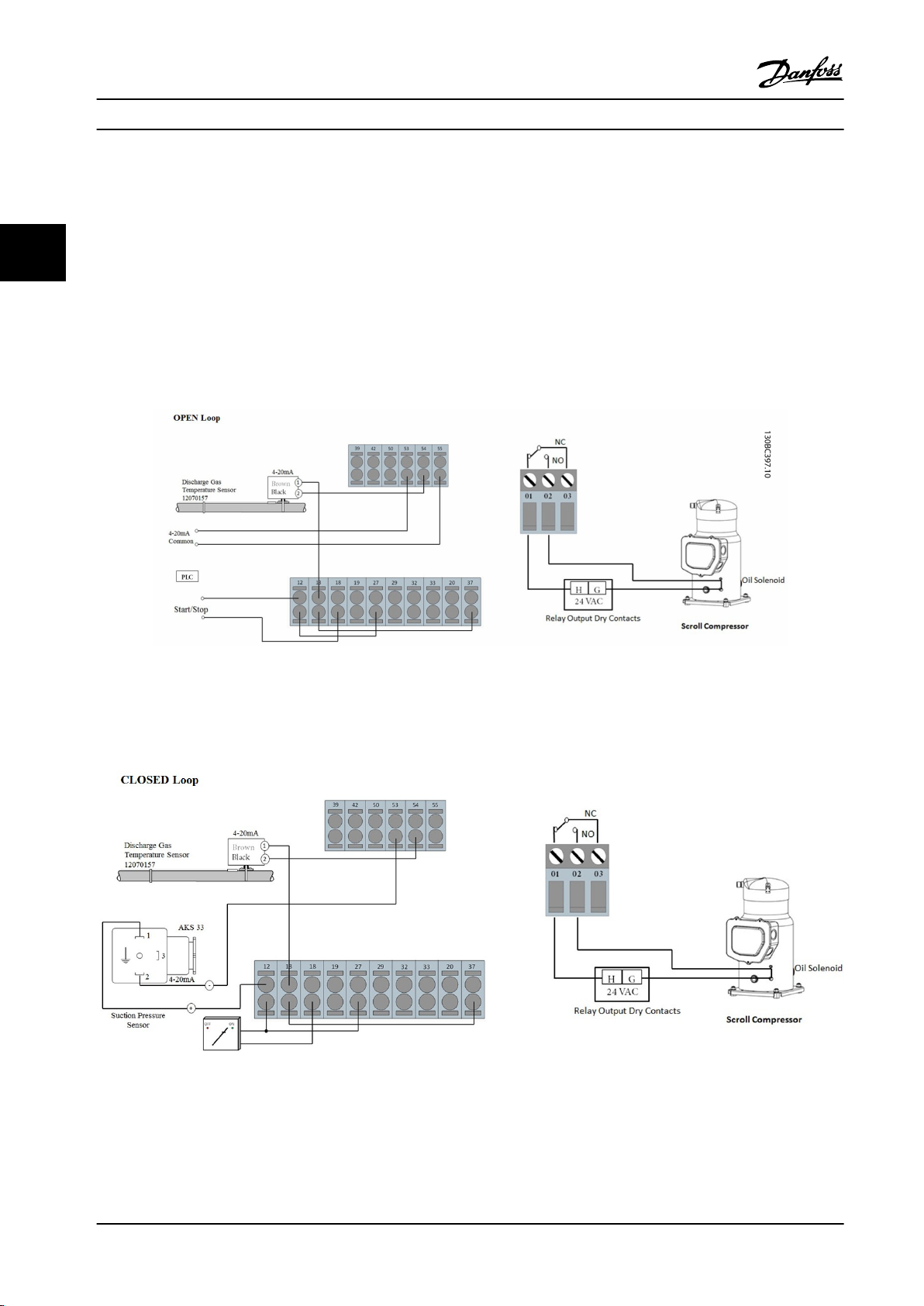
4.1.2 Open Loop with External Reference
1. Apply analog speed reference signal (0-10 V) on
terminal 53 using the terminal 55 as common.
See chapter 3.3.14 Basic Examples of Control
Connections.
2. Check if switch A53 is positioned to U (voltage)
instead of I (current). The switch A53 is on the
MG34M422 Danfoss A/S © Rev. 2013-07-03 All rights reserved. 37
4. Done.
4.1.3 PID Closed Loop with 4-20 mA
Pressure Transmitter
1. Connect pressure transmitter to analog input on
terminal 54 according to chapter 3.3.14 Basic
Examples of Control Connections.
2. Make sure that the switch for analogue input 54
is set to “I” for current input.
3. Press [Quick Menu], go to “PID Closed Loop” and
then to “Basic PID Settings) menu.
Now change parameters to
Page 40

Quick Set-up
VLT® Compressor Drives CDS 302/CDS 303
parameter 1-00 Conguration Mode: Select [3]
Process
parameter 3-01 Reference/Feedback Unit: Select [71]
Psi
parameter 3-02 Minimum Reference and
parameter 3-03 Maximum Reference: Enter the
lower and upper limits of the setpoint range [psi].
44
parameter 3-15 Reference Resource 1: Select [0] No
function for xed setpoint.
parameter 6-22 Terminal 54 Low Current +
parameter 6-23 Terminal 54 High Current: The
values of these parameters should match the
output of the pressure transmitter (4-20 mA for
example is the factory setting).
parameter 6-24 Terminal 54 Low Ref./Feedb. Value +
parameter 6-25 Terminal 54 High Ref./Feedb. Value:
Set range of pressure transmitter (factory setting
-14/+174 psi)
Return to parameter 3-13 Reference Site: Select [2]
Local to run with a xed setpoint adjustable via
LCP. Select [1] Remote if the setpoint is given by
This is what the screen will look like, after conguring the
frequency converter for Closed loop application.
Figure 4.3 Closed Loop
For more details on PID Closed Loop, see Figure 4.4.
the analog input (as dened in
parameter 3-15 Reference Resource 1).
4. Press [Quick Menu], go to My Personal Menu, go
to parameter 0-22 Display Line 1.3 Small and select
[1652] Feedback [unit]. The pressure [psi] is going
to be shown in the upper right corner of the
display
5. Ready to Run: Press [Hand On] and set reference
in psi using the arrows on the display. Before
leaving the site, never forget the next step.
6. Ready to Run: Press [Auto On].
Figure 4.4 Example of Closed Loop Application
38 Danfoss A/S © Rev. 2013-07-03 All rights reserved. MG34M422
Page 41

Quick Set-up Operating Instructions
4.1.4 Other Compressor Features
To set up other dedicated compressor features press [Quick Menu] and go to Q4 or follow Figure 4.5.
4 4
Figure 4.5 Flowchart
MG34M422 Danfoss A/S © Rev. 2013-07-03 All rights reserved. 39
Page 42

Auto
on
Reset
Hand
on
O
Status
Quick
Menu
Main
Menu
Alarm
Log
Back
Cancel
Info
OK
Status
1(0)
1234rpm 10,4A 43,5Hz
Run OK
43,5Hz
On
Alarm
Warn.
130BA018.13
1
2
3
4
b
a
c
How to Program
VLT® Compressor Drives CDS 302/CDS 303
5 How to Program
5.1 How to Program on the Graphical LCP
5.1.1 Control Panel
The following instructions are valid for the graphical LCP
(LCP 102):
55
The control panel is divided into four functional groups:
1. Graphical display with Status lines. All data is
displayed in a graphical LCP display, which can
show up to ve items of operating data while
displaying [Status].
2. Menu keys and indicator lights - changing
parameters and switching between display
functions.
3. Navigation keys and indicator lights (LEDs).
4. Operation keys and indicator lights (LEDs).
Figure 5.1 Overview of LCP
5.1.2 Display Lines
a. Status line:
Status messages displaying icons and graphic.
b. Line 1-2:
Operator data lines displaying data dened or chosen by
the user. By pressing the [Status] key, up to one extra line
can be added.
c. Status line:
Status messages displaying text.
5.1.3 Display Contrast Adjustment
Press [Status] and [ ▼ ] for darker display
Press [Status] and [ ▲ ] for brighter display
40 Danfoss A/S © Rev. 2013-07-03 All rights reserved. MG34M422
Page 43

On
Warn.
Alarm
130BP044.10
130BP045.10
Status
Quick
Menu
Main
Menu
Alarm
Log
How to Program Operating Instructions
5.1.4 Indicator Lights
If certain threshold values are exceeded, the alarm and/or
warning LED lights up. A status and alarm text appear on
the control panel. The on LED is activated when the
frequency converter receives mains voltage.
Green LED/On: Control section is working.
•
Yellow LED/Warn.: Indicates a warning.
•
Flashing Red LED/Alarm: Indicates an alarm
•
Figure 5.2 Indicator Lights
[Quick Menu] allows quick access to dierent Quick Menus
such as:
Q1 - My Personal Menu
Q2 - Quick Set-up
Q3 – PID Process Loop
Q4 - Compressor Functions
Q5 - Changes Made
Q6 - Loggings
Q7 - Load Prole
Use [Quick Menu] for programming the parameters
belonging to the Quick Menu. It is possible to switch
directly between Quick Menu mode and Main Menu mode.
5.2.2 Navigation Keys
The 4 navigation keys are used to navigate between the
dierent choices available in [Quick Menu], [Main Menu]
and [Alarm Log]. Press the keys to move the cursor.
[OK] is used for choosing a parameter marked by the
cursor and for enabling the change of a parameter and
loggings from Quick Menu.
5 5
5.2 LCP Keys
5.2.1 Function Keys
The control keys are divided into functions. The keys below
the display and indicator lamps are used for parameter setup, including choice of display indication during normal
operation.
Figure 5.3 Function Keys
[Status] indicates the status of the frequency converter
and/or the compressor motor. Choose between 3 dierent
readouts by pressing the [Status] key: 5 line readouts, 4
line readouts or Smart Logic Control by pushing [Status]
twice.
Press [Status] to select the display mode or to change back
to Display mode from either Quick Menu mode, Main
Menu mode or Alarm mode. Also press [Status] to toggle
single or double read-out mode.
5.2.3 Local Control Keys
Local control keys for local control are found at the bottom
of the control panel.
Figure 5.4 Local Control Keys
MG34M422 Danfoss A/S © Rev. 2013-07-03 All rights reserved. 41
Page 44

How to Program
VLT® Compressor Drives CDS 302/CDS 303
[Hand On] enables control of the frequency converter via
the LCP. [Hand on] also starts the motor compressor, and it
is now possible to enter the motor compressor speed data
by means of the arrow keys. The key can be selected as [1]
Enable or [0] Disable via parameter 0-40 [Hand on] Key on
LCP.
External stop signals activated by means of control signals
or a serial bus will override a “start“ command via the LCP.
The following control signals will still be active when
[Hand on] is activated:
55
[Hand On] - [O] - [Auto On]
•
Reset
•
Coasting stop inverse
•
Reversing
•
Set-up select lsb (least signicant bit) - Set-up
•
select msb (most signicant bit)
Stop command from serial communication
•
Quick stop
•
DC brake
•
[O] stops the connected motor compressor. The key can
be selected as [1] Enable or [0] Disable via
parameter 0-41 [O] Key on LCP.
If no external stop function is selected and the [O] key is
inactive the motor compressor can be stopped by disconnecting the voltage.
[Auto On] enables the frequency converter is to be
controlled via the control terminals and/or serial communication. When a start signal is applied on the control
terminals and/or the bus, the frequency converter will
start. The key can be selected as [1] Enable or [0] Disable
via parameter 0-42 [Auto on] Key on LCP.
NOTICE!
An active HAND-OFF-AUTO signal via the digital inputs
has higher priority than the control keys [Hand on] and
[Auto on].
[Reset] is used for resetting the frequency converter after
an alarm (trip). It can be selected as [1] Enable or [0]
Disable via parameter 0-43 [Reset] Key on LCP.
The parameter shortcut can be carried out by holding
down the [Main Menu] key for 3 seconds. The parameter
shortcut allows direct access to any parameter.
5.2.4 Quick Transfer of Parameter Settings
Once the set-up of a frequency converter is complete,
store the data in the LCP or on a PC via MCT 10 Set-up
Software.
5.2.5 Data Storage in LCP
1. Go to parameter 0-50 LCP Copy in the Main Menu.
2. Press [OK].
3. Select [1] All to LCP.
4. Press [OK].
All parameter settings are now stored in the LCP indicated
by the progress bar. When 100% is reached, press [OK].
NOTICE!
Stop the motor compressor before performing this
operation. The LCP can now be connected to another
frequency converter and the parameter settings copied
to this frequency converter as well.
5.2.6 Initialization to Default Settings
Initialize the frequency converter to default settings in two
ways:
Recommended initialization (via
parameter 14-22 Operation Mode)
1. Select parameter 14-22 Operation Mode.
2. Press [OK].
3. Select [2] Initialization.
4. Press [OK].
5. Disconnect mains supply and wait until the
display turns o.
6. Reconnect the mains supply.
7. Drive initialized [A80] (Alarm 80) appears - the
frequency converter is now reset.
parameter 14-22 Operation Mode initializes all except:
parameter 8-30 Protocol
•
parameter 8-31 Address
•
parameter 8-32 FC Port Baud Rate
•
parameter 8-33 Parity / Stop Bits
•
parameter 8-34 Estimated cycle time
•
parameter 8-35 Minimum Response Delay
•
parameter 8-36 Max Response Delay
•
42 Danfoss A/S © Rev. 2013-07-03 All rights reserved. MG34M422
Page 45

How to Program Operating Instructions
parameter 8-37 Max Inter-Char Delay
•
parameter 14-50 RFI 1
•
parameter 15-00 Operating hours
•
parameter 15-01 Running Hours
•
parameter 15-02 kWh Counter
•
parameter 15-03 Power-ups
•
parameter 15-04 Over Temps
•
parameter 15-05 Over Volts
•
parameter 15-20 Historic Log: Event
•
parameter 15-21 Historic Log: Value
•
parameter 15-22 Historic Log: Time
•
parameter 15-30 Fault Log: Error Code
•
parameter 15-31 Fault Log: Value
•
parameter 15-32 Fault Log: Time
•
Manual initialization
1. Disconnect from mains and wait until the display
turns o.
2. Press [Status] - [Main Menu] - [OK] at the same
time while power up for LCP 102, Graphical
Display.
3. Release the keys after 5 s.
4. The frequency converter is now programmed
according to default settings.
This procedure initializes all except:
The parameter settings stored in the LCP are now
transferred to the frequency converter indicated by the
progress bar. When 100% is reached, press [OK].
5 5
parameter 15-00 Operating hours
•
parameter 15-03 Power-ups
•
parameter 15-04 Over Temps
•
parameter 15-05 Over Volts
•
5.2.7 Data Transfer from LCP to Frequency
Converter
NOTICE!
Stop the motor compressor before performing this
operation.
1. Go to parameter 0-50 LCP Copy.
2. Press [OK].
3. Select [2] All from LCP.
4. Press [OK] again.
MG34M422 Danfoss A/S © Rev. 2013-07-03 All rights reserved. 43
Page 46

How to Program
VLT® Compressor Drives CDS 302/CDS 303
5.2.8 Parameter Selection
In the Main menu mode, the parameters are divided into
groups. Use the navigation keys for selecting a parameter
group.
The following parameter groups are accessible:
0-** Operation/Display
•
1-** Load/Motor
•
3-** Reference/Ramps
55
•
4-** Limits/Warnings
•
5-** Digital In/Out
•
6-** Analog In/Out
•
7-** Controls
•
8-** Comm. and Options
•
13-** Smart Logic
•
14-** Special Functions
•
15-** Drive Information
•
16-** Data Readouts
•
25-** Cascade Controller
•
28-** Compressor Functions
•
After selecting a parameter group, select a parameter with
the navigation keys. The middle section on the display
shows the parameter number and name as well as the
selected parameter value.
Figure 5.5 Display Example - Parameter Selection
44 Danfoss A/S © Rev. 2013-07-03 All rights reserved. MG34M422
Page 47

How to Program Operating Instructions
5.2.9 Changing Data
The procedure for changing data is the same in both the
Quick menu and the Main menu mode.
Press [OK] to change the selected parameter. The
procedure for changing data depends on whether the
selected parameter represents a numerical data value or a
text value.
5.2.10 Changing a Text Value
If the selected parameter is a text value, change the text
value by pressing the [▲]/[▼] navigation keys. [▲] increases
the value and [▼] decreases the value. Place the cursor on
the value and press [OK] to save.
5.2.11 Changing a Group of Numeric Data
Values
If the chosen parameter represents a numeric data value,
change it by pressing the navigation keys. Press [◀]/[▶] to
move the cursor horizontally. Press [▲]/[▼] to change the
data value. [▲] increases the data value, and [▼] decreases
the data value. Place the cursor on the value and press
[OK] to save.
5 5
Figure 5.6 Display Example
MG34M422 Danfoss A/S © Rev. 2013-07-03 All rights reserved. 45
Page 48

6
Parameter Descriptions
VLT® Compressor Drives CDS 302/CDS 303
6 Parameter Descriptions
6.1 LCP Display
6.1.1 LCP Programming
Table 6.1 lists the parameters that cannot be changed from the LCP. These parameters are dened by the compressor choice
made in 1-13 Compressor Selection.
Parameter Parameter Parameter
parameter 1-01 Motor Control Principle 1-45 q-axis Inductance (Lq) 200% I
parameter 1-03 Torque Characteristics parameter 1-40 Back EMF at 1000 RPM parameter 5-42 O Delay, Relay
parameter 1-04 Overload Mode parameter 1-47 Low Speed Torque Calibration parameter 7-00 Speed PID Feedback Source
parameter 1-05 Local Mode Conguration 1-49 Current at min. inductance parameter 7-02 Speed PID Proportional Gain
parameter 1-10 Motor Construction parameter 1-62 Slip Compensation parameter 7-03 Speed PID Integral Time
parameter 1-20 Motor Power [kW] parameter 1-66 Min. Current at Low Speed parameter 7-04 Speed PID Dierentiation Time
parameter 1-22 Motor Voltage parameter 1-68 Minimum Inertia parameter 7-05 Speed PID Di. Gain Limit
parameter 1-23 Motor Frequency parameter 1-69 Maximum Inertia parameter 13-10 Comparator Operand
parameter 1-24 Motor Current parameter 1-71 Start Delay parameter 13-11 Comparator Operator
parameter 1-25 Motor Nominal Speed parameter 1-72 Start Function parameter 13-12 Comparator Value
parameter 1-26 Motor Cont. Rated Torque parameter 1-73 Flying Start parameter 14-00 Switching Pattern
parameter 1-29 Automatic Motor
Adaptation (AMA)
parameter 1-30 Stator Resistance (Rs) parameter 1-76 Start Current parameter 14-10 Line Failure
parameter 1-31 Rotor Resistance (Rr)
parameter 1-33 Stator Leakage Reactance
(X1)
parameter 1-34 Rotor Leakage Reactance
(X2)
parameter 1-35 Main Reactance (Xh) parameter 3-82 Starting Ramp Up Time parameter 14-26 Trip Delay at Inverter Fault
parameter 1-36 Iron Loss Resistance (Rfe) parameter 4-10 Motor Speed Direction parameter 28-30 Crankcase Heating Control
parameter 1-37 d-axis Inductance (Ld) parameter 4-11 Motor Speed Low Limit [RPM] parameter 28-31 Heating DC Current
parameter 1-38 q-axis Inductance (Lq) parameter 4-13 Motor Speed High Limit [RPM] parameter 28-40 Reverse Protection Control
parameter 1-39 Motor Poles parameter 4-16 Torque Limit Motor Mode parameter 28-41 DC Brake Current
parameter 1-40 Back EMF at 1000 RPM parameter 4-18 Current Limit parameter 28-42 DC Braking Time
1-44 d-axis Inductance (Ld) 200% I
NOM
parameter 1-74 Start Speed [RPM] parameter 14-01 Switching Frequency
parameter 1-77 Compressor Start Min Speed
[RPM]
parameter 1-79 Compressor Start Max Time to
Trip
parameter 1-86 Compressor Min. Speed for
Trip [RPM]
parameter 4-19 Max Output Frequency parameter 28-43 DC Brake Cut In Speed [RPM]
NOM
parameter 5-41 On Delay, Relay
parameter 14-11 Line Voltage at Line Fault
parameter 14-21 Automatic Restart Time
parameter 14-25 Trip Delay at Torque Limit
Table 6.1 Compressor Related Parameters
46 Danfoss A/S © Rev. 2013-07-03 All rights reserved. MG34M422
Page 49

Parameter Descriptions Operating Instructions
6.2 Par. Group 0 - Operation and Display
6.2.1 0-0* Basic Settings
0-01 Language
Option: Function:
[0] English
[1] Deutsch
[2] Francais
[3] Dansk
[4] Spanish
[5] Italiano
[10] Chinese
[28] Bras.port
[39] Korean
[42] Trad.Chinese
[49] Russian
0-02 Motor Speed Unit
Option: Function:
Select display of motor speed parameters (i.e.
references, feedbacks and limits) in terms of shaft
speed (RPM) or output frequency to the motor (Hz).
[0] RPM
[1] Hz
NOTICE!
This parameter cannot be adjusted while the motor is
running.
0-04 Operating State at Power-up (Hand)
Option: Function:
Selects the operating mode upon reconnection
of the frequency converter to mains voltage
after power down in Hand (local) operation
mode.
[0] Resume Restarts the frequency converter, maintaining
the same and the same start/stop settings
(applied by [Hand On/O]) as before the
frequency converter was powered down.
[1] Forced stop,
ref=old
[2] Forced stop,
ref=0
Restarts the frequency converter with a saved
local reference, after mains voltage reappears
and after pressing [Hand On].
Resets the local reference to 0 upon restarting
the frequency converter.
0-10 Active Set-up
Option: Function:
[0] Factory
setup
[1] Set-up 1 [1] Set-up 1 to [4] Set-up 4 are the four separate
[2] Set-up 2
[3] Set-up 3
[4] Set-up 4
[9] Multi Set-upRemote selection of set-ups using digital inputs
Cannot be changed. It contains the Danfoss
data set, and can be used as a data source
when returning the other set-ups to a known
state.
parameter set-ups within which all parameters
can be programmed.
and the serial communication port. This set-up
uses the settings from parameter 0-12 This Set-
up Linked to. Stop the frequency converter
before making changes to open- and closed
loop functions
Use parameter 0-51 Set-up Copy to copy a set-up to one or
all other set-ups. Stop the frequency converter before
switching between set-ups where parameters marked ‘not
changeable during operation’ have dierent values. To
avoid conicting settings of the same parameter within
two dierent set-ups, link the set-ups together using
parameter 0-12 This Set-up Linked to. Parameters which are
‘not changeable during operation’ are marked FALSE in the
parameter lists in chapter 6.16 Parameter Lists.
0-11 Edit Set-up
Option: Function:
Select the set-up to be edited (i.e.
programmed) during operation; either the
active set-up or one of the inactive set-ups.
[0] Factory
setup
[1] Set-up 1 [1] Set-up 1 to [4] Set-up 4 can be edited freely
[2] Set-up 2
[3] Set-up 3
[4] Set-up 4
[9] Active Set-upCan also be edited during operation. Edit the
Cannot be edited but it is useful as a data
source to return the other set-ups to a known
state.
during operation, independently of the active
set-up.
chosen set-up from a range of sources: LCP, FC
RS-485, FC USB or up to ve eldbus sites.
6
6
0-10 Active Set-up
Option: Function:
Select the set-up to control the frequency
converter functions.
MG34M422 Danfoss A/S © Rev. 2013-07-03 All rights reserved. 47
Page 50

130BP075.10
130BP076.10
6
Parameter Descriptions
VLT® Compressor Drives CDS 302/CDS 303
0-12 This Set-up Linked to
Option: Function:
parameter 0-12 This Set-up Linked to to [1] Set-up
1. This will start the linking (synchronizing)
process.
Figure 6.2 Set-up 1
OR
2. While still in Set-up 1, copy Set-up 1 to Set-up
2. Then set parameter 0-12 This Set-up Linked to to
[2] Set-up 2. This will start the linking process.
Figure 6.1 Edit Set-up
0-12 This Set-up Linked to
Option: Function:
To enable conict-free changes from one set-up
to another during operation, link set-ups
containing parameters which are not changeable
during operation. The link will ensure synchronizing of the ‘not changeable during operation’
parameter values when moving from one set-up
to another during operation. ‘Not changeable
during operation’ parameters can be identied by
the label FALSE in the parameter lists in
chapter 6.16 Parameter Lists.
Parameter 0-12 This Set-up Linked to is used by
Multi set-up in parameter 0-10 Active Set-up. Multi
set-up is used to move from one set-up to
another during operation (i.e. while the motor is
running).
Example:
Use Multi set-up to shift from Set-up 1 to Set-up
2 whilst the motor is running. Program in Set-up
1 rst, then ensure that Set-up 1 and Set-up 2
are synchronized (or ‘linked’). synchronization can
be performed in two ways:
1. Change the edit set-up to [2] Set-up 2 in
parameter 0-11 Edit Set-up and set
Figure 6.3 Set-up 2
After the link is complete,
parameter 0-13 Readout: Linked Set-ups will read
{1,2} to indicate that all ‘not changeable during
operation’ parameters are now the same in Setup 1 and Set-up 2. If there are changes to a ‘not
changeable during operation’ parameter, e.g.
parameter 1-30 Stator Resistance (Rs), in Set-up 2,
they will also be changed automatically in Set-up
1. A switch between Set-up 1 and Set-up 2
during operation is now possible.
[0] Not linked
[1] Set-up 1
[2] Set-up 2
[3] Set-up 3
[4] Set-up 4
48 Danfoss A/S © Rev. 2013-07-03 All rights reserved. MG34M422
Page 51

Parameter Descriptions Operating Instructions
0-13 Readout: Linked Set-ups
Array [5]
Range: Function:
0 * [0 -
255 ]
View a list of all the set-ups linked by means of
parameter 0-12 This Set-up Linked to. The
parameter has one index for each parameter setup. The parameter value displayed for each index
represents which set-ups are linked to that
parameter set-up.
Index LCP value
0 {0}
1 {1,2}
2 {1,2}
3 {3}
4 {4}
Table 6.3 Example: Set-up 1 and Set-up 2 are
linked
0-14 Readout: Edit Set-ups / Channel
Range: Function:
0 * [-2147483648 -
2147483647 ]
View the setting of parameter 0-11 Edit
Set-up for each of the four dierent
communication channels. When the
number is displayed in hex, as it is in the
LCP, each number represents one channel.
Numbers 1-4 represent a set-up number;
‘F’ means factory setting; and ‘A’ means
active set-up. The channels are, from right
to left: LCP, FC-bus, USB, HPFB1-5.
Example: The number AAAAAA21h means
that the FC bus selected Set-up 2 in
parameter 0-11 Edit Set-up, the LCP
selected Set-up 1 and all others used the
active set-up.
6.2.2 0-2* LCP Display
Dene the display in the Graphical Logic Control Panel.
0-20 Display Line 1.1 Small
Option: Function:
Select a variable for
display in line 1, left
position.
[0] None
[953] Probus Warning Word
[1005] Readout Transmit Error Counter
[1006] Readout Receive Error Counter
[1007] Readout Bus O Counter
[1013] Warning Parameter
0-20 Display Line 1.1 Small
Option: Function:
[1501] Running Hours
[1502] kWh Counter
[1508] Number of Starts
[1509] Number of Auto Resets
[1600] Control Word
[1601] Reference [Unit]
[1602] Reference %
[1603] Status Word
[1605] Main Actual Value [%]
[1609] Custom Readout
[1610] Power [kW]
[1611] Power [hp]
[1612] Motor Voltage
[1613] Frequency
[1614] Motor current
[1615] Frequency [%]
[1616] Torque [Nm]
[1617] Speed [RPM]
[1618] Motor Thermal
[1619] KTY sensor temperature
[1620] Motor Angle
[1622] Torque [%]
[1630] DC Link Voltage
[1632] Brake Energy /s
[1633] Brake Energy /2 min
[1634] Heatsink Temp.
[1635] Inverter Thermal
[1636] Inv. Nom. Current
[1637] Inv. Max. Current
[1638] SL Controller State
[1639] Control Card Temp.
[1650] External Reference
[1651] Pulse Reference
[1652] Feedback[Unit]
[1653] Digi Pot Reference
[1654] Feedback 1 [Unit]
[1655] Feedback 2 [Unit]
[1660] Digital Input
[1661] Terminal 53 Switch Setting
[1662] Analog Input 53
[1663] Terminal 54 Switch Setting
[1664] Analog Input 54
[1665] Analog Output 42 [mA]
[1666] Digital Output [bin]
[1667] Freq. Input #29 [Hz]
[1668] Freq. Input #33 [Hz]
[1669] Pulse Output #27 [Hz]
[1670] Pulse Output #29 [Hz]
[1671] Relay Output [bin]
[1672] Counter A
6
6
MG34M422 Danfoss A/S © Rev. 2013-07-03 All rights reserved. 49
Page 52

Parameter Descriptions
VLT® Compressor Drives CDS 302/CDS 303
6
0-20 Display Line 1.1 Small
Option: Function:
[1673] Counter B
[1680] Fieldbus CTW 1
[1682] Fieldbus REF 1
[1684] Comm. Option STW
[1685] FC Port CTW 1
[1686] FC Port REF 1
[1690] Alarm Word
[1691] Alarm Word 2
[1692] Warning Word
[1693] Warning Word 2
[1694] Ext. Status Word
[2580] Cascade Status
[2581] Compressor Status
[2587] Inverse Interlock
[2827] Discharge Temperature
[9913] Idle time
[9914] Paramdb requests in queue
[9917] tCon1 time
[9918] tCon2 time
[9919] Time Optimize Measure
0-25 My Personal Menu
Range: Function:
Size
related*
[0 9999 ]
Dene up to 20 parameters to include in
the Q1 Personal Menu, accessible via the
[Quick Menu] key on the LCP. The
parameters will be displayed in the Q1
Personal Menu in the order they are
programmed into this array parameter.
Delete parameters by setting the value to
« 0000 ».
0-21 Display Line 1.2 Small
Option: Function:
Options are the same as in
parameter 0-20 Display Line 1.1 Small
[1614] * Motor Current
[A]
0-22 Display Line 1.3 Small
Option: Function:
Options are the same as in
parameter 0-20 Display Line 1.1 Small.
[1610] * Power [kW]
0-23 Display Line 2 Large
Option: Function:
Options are the same as in
parameter 0-20 Display Line 1.1 Small.
[1613] * Frequency [Hz]
0-24 Display Line 3 Large
Option: Function:
Options are the same as in
parameter 0-20 Display Line 1.1 Small.
[1662] * Analog Input
53
0-30 Unit for User-dened Readout
Option: Function:
It is possible to program a value to be
shown in the display of the LCP. The value
will have a linear, squared or cubed relation
to speed. This relation will depend on the
unit selected (see ). The actual calculated
value can be read in parameter 16-09 Custom
Readout, and/or shown in the display be
selecting [16-09] Custom Readout in
parameter 0-20 Display Line 1.1 Small to
parameter 0-24 Display Line 3 Large.
[0] None
[1] %
[5] PPM
[10] min
[11] RPM
[12] PULSE/s
[20] liter / sec.
[21] liter / min
[22] liter / hr.
[23] m³ / sec.
[24] m³/min
[25] m³ / hr.
[30] kg / sec.
[31] kg/min
[32] kg / hr.
[33] ton / min
[34] ton / hr.
[40] m / sec.
[41] m/min
[45] m
[60] °C
[70] mbar
[71] bar
[72] Pa
[73] kPa
[74] m WG
[80] kW
[120] GPM
[121] gal / sec.
[122] gal/min
[123] gal / hr.
[124] CFM
[125] ft³/s
50 Danfoss A/S © Rev. 2013-07-03 All rights reserved. MG34M422
Page 53

Parameter Descriptions Operating Instructions
0-30 Unit for User-dened Readout
Option: Function:
[126] ft³/min
[127] ft³/h
[130] lbs / sec.
[131] lbs / min.
[132] lbs / hr.
[140] ft/s
[141] ft/min
[145] ft
[160] °F
[170] psi
[171] lb/in²
[172] in. wtr. gage
[173] ft WG
[180] HP
0-31 Min Value of User-dened Readout
Range: Function:
0 CustomReadoutUnit*
[ -999999.99 par. 0-32
CustomReadoutUnit]
This parameter sets the min.
value of the custom dened
readout (occurs at zero speed).
Only possible to set dierent
from 0 is when selecting a
linear unit in
parameter 0-30 Unit for Userdened Readout. For Quadratic
and Cubic units the minimum
value will be 0.
0-32 Custom Readout Max Value
Range: Function:
100 CustomReadoutUnit*
[ par. 0-31 -
999999.99
CustomReadoutUnit]
This parameter sets the max
value to be shown when the
speed of the motor has reached
the set value for
parameter 4-13 Motor Speed High
Limit [RPM] or
parameter 4-14 Motor Speed High
Limit [Hz] (depends on setting in
parameter 0-02 Motor Speed
Unit).
6.2.3 0-4* LCP Keypad
Enable and disable individual keys on the LCP keypad.
0-40 [Hand on] Key on LCP
Option: Function:
If parameter 0-40 [Hand on] Key on LCP is included
in the Quick Menu, then dene the password in
parameter 0-65 Quick Menu Password.
0-40 [Hand on] Key on LCP
Option: Function:
[0] Disabled Prevents accidental start of the frequency
converter in Hand mode.
[1] Enabled Prevents unauthorised start in Hand mode.
[2] Password
0-41 [O] Key on LCP
Option: Function:
Options are the same as in parameter 0-40 [Hand on]
Key on LCP.
0-42 [Auto on] Key on LCP
Option: Function:
Options are the same as in parameter 0-40 [Hand on]
Key on LCP.
0-43 [Reset] Key on LCP
Option: Function:
Options are the same as in parameter 0-40 [Hand on]
Key on LCP.
6.2.4 0-5* Copy/Save
Copy parameter settings between set-ups and to/from the
LCP.
0-50 LCP Copy
Option: Function:
[0] * No copy
[1] All to LCP Copies all parameters in all set-ups from
the frequency converter memory to the
LCP memory.
[2] All from LCP Copies all parameters in all set-ups from
the LCP memory to the frequency
converter memory.
[3] Size indep.
from LCP
0-51 Set-up Copy
Option: Function:
[0] No copy
[1] Copy to set-up 1 Copies all parameters in the present edit
[2] Copy to set-up 2
[3] Copy to set-up 3
[4] Copy to set-up 4
[9] Copy to all Copies the parameters in the present set-
Copies only the parameters that are
independent of the motor size.
set-up (dened in par. 0-11 Edit Set-up) to
Set-up 1. Likewise, select the option
corresponding to the other set-up(s).
up over to each of the set-ups 1 to 4.
6
6
MG34M422 Danfoss A/S © Rev. 2013-07-03 All rights reserved. 51
Page 54

6
Parameter Descriptions
6.2.5 0-6* Password
Dene password access to menus.
0-60 Main Menu Password
Option: Function:
[Size
related] *
0-60 Main Menu Password
Range: Function:
100 * [0 - 999 ]
0-65 Quick Menu Password
Option: Function:
Dene the password for access to the Main Menu
via the [Main Menu] key. If parameter 0-61 Access
to Main Menu w/o Password is set to [0] Full access,
this parameter will be ignored.
Dene the password for access to the Quick Menu via
the [Quick Menu] key. If parameter 0-66 Access to Quick
Menu w/o Password is set to [0] Full access, this
parameter will be ignored.
VLT® Compressor Drives CDS 302/CDS 303
0-66 Access to Quick Menu w/o Password
Option: Function:
NOTICE!
If parameter 0-61 Access to Main Menu
w/o Password is set to [0] Full access, this
parameter will be ignored.
[ 0] * Full access Disables the password dened in
parameter 0-65 Quick Menu Password.
[1] Read only Prevents unauthorized editing of Quick Menu
parameters.
[2] No access Prevents unauthorized viewing and editing of
Quick Menu parameters.
52 Danfoss A/S © Rev. 2013-07-03 All rights reserved. MG34M422
Page 55

Parameter Descriptions Operating Instructions
6.3 Par. Group 1 - Load and Motor
6.3.1 1-0* General Settings
Dene whether the frequency converter operates in speed
mode or torque mode; and whether the internal PID
control should be active or not. All parameters from
parameter 1-01 Motor Control Principle (included) to
parameter 1-81 Min Speed for Function at Stop [RPM]
(included) are read only. Only parameter 1-13 Compressor
Selection remains accessible for compressor selection.
1-00 Conguration Mode
Option: Function:
NOTICE!
This parameter cannot be adjusted while
the motor is running.
Select the application control principle to be
used when a Remote Reference (via analog
input) is active. A Remote Reference can only be
active when 3-13 Reference Site is set to [0] or
[1].
[0] * Speed
open
loop
[3] Process Enables the use of process control in the
Enables speed control (without feedback signal
from motor) to the input signal over the
compressor speed range.
frequency converter. The process control
parameters are set in parameter groups 7-2*
Process PID Feedback and 7-3* Process PID
Control.
6
6
1-13 Compressor Selection
Range: Function:
The default setting of most of the parameters
in the frequency converter (e.g. motor data,
limits, ramps etc.) depends upon the
compressor and system refrigerant selected for
the frequency converter.
The frequency converter selects the default
compressor based upon the power size and
voltage range for the frequency converter.
Under normal circumstances this should not
be changed. During test/repair situations a
dierent compressor can be selected – or if
the system is not using the default refrigerant.
NOTICE!
If the compressor selection is changed,
then all dependent parameters reset to
default and any user settings will be
lost.
Size
dependent.
[] Select the compressor/refrigerant combination
for the system.
MG34M422 Danfoss A/S © Rev. 2013-07-03 All rights reserved. 53
Page 56

Parameter Descriptions
VLT® Compressor Drives CDS 302/CDS 303
6
6.4 Par. Group 3 - Reference/Ramps
6.4.1 3-0* Reference Limits
Parameters for reference handling, denition of limitations,
conguration of the reaction of the frequency
and
converter to changes.
3-00 Reference Range
Option: Function:
Select the range of the reference signal and
the feedback signal. Signal values can be
positive only, or positive and negative. The
minimum limit may have a negative value,
unless [1] Speed closed loop control is selected
in 1-00 Conguration Mode.
[0] * Min. - Max For positive values only
[1] -Max -
+Max
3-01 Reference/Feedback Unit
Option: Function:
[0] None
[71] * bar
[60] °C
[160] °F
[170] psi
3-02 Minimum Reference
Option: Function:
3-03 Maximum Reference
Option: Function:
For both positive and negative values
Select the unit to be used in Process PID Control
references and feedbacks.
Enter the minimum reference. The minimum reference
is the lowest value obtainable by summing all
references. Minimum reference is active only when
parameter 3-00 Reference Range is set to [0] Min.- Max..
The minimum reference unit matches:
The choice of conguration in
•
parameter 1-00 Conguration Mode: for [1]
Speed closed loop.
The unit selected in parameter 3-01 Reference/
•
Feedback Unit.
Enter the maximum reference.
3-10 Preset Reference
Array [8]
0.00%* [-100.00
-
100.00 %
]
Must remain 0 for Open Loop Control.
The preset reference is stated as a percentage
of the value Ref
Reference) or as a percentage of the other
external references. If a Ref
(parameter 3-02 Minimum Reference) is
programmed, the preset reference is
calculated as a percentage of the full
reference range, i.e. on the basis of the
dierence between Ref
Afterwards, the value is added to Ref
When using preset references, select [16]
Preset ref. bit 0, [17] Preset ref. bit 1 or [18]
Preset ref. bit 2 for the corresponding digital
inputs in parameter group 5-1* Digital Inputs.
(parameter 3-03 Maximum
MAX
0
MIN
and Ref
MAX
MIN
.
MIN
.
3-12 Catch up/slow-down value
Range: Function:
0 %* [0 -
100 %]
Enter a percentage (relative) value to be either
added to or deducted from the actual reference
for Catch up or Slow down respectively. If Catch up
is selected via one of the digital inputs
(parameter 5-10 Terminal 18 Digital Input to
parameter 5-15 Terminal 33 Digital Input), the
percentage (relative) value is added to the total
reference. If Slow down is selected via one of the
digital inputs (parameter 5-10 Terminal 18 Digital
Input to parameter 5-15 Terminal 33 Digital Input),
the percentage (relative) value is deducted from
the total reference. Obtain extended functionality
with the DigiPot function. See parameter group
3-9* Digital Potentiometer.
3-13 Reference Site
Option: Function:
Select which reference site to activate.
[0] Linked to
Hand / Auto
[1] Remote Use the remote reference in both Hand mode
[2] Local Use the local reference in both Hand mode
Use the local reference when in Hand mode;
or the remote reference when in Auto mode
and Auto mode
and Auto mode
3-14 Preset Relative Reference
Range: Function:
0.00%* [-100.00 -
100.00 %]
Dene a xed value (in %) to be added to
the variable value (dened in 3-18 Relative
Scaling Reference Source). The sum of the
xed and variable values is multiplied with
the actual reference. This product is then
54 Danfoss A/S © Rev. 2013-07-03 All rights reserved. MG34M422
Page 57

Parameter Descriptions Operating Instructions
3-14 Preset Relative Reference
Range: Function:
added to the actual reference (X+X*Y/100)
to give the resultant actual reference.
3-15 Reference Resource 1
Option: Function:
NOTICE!
This parameter cannot be adjusted
while the motor is running.
Select the reference input to be used for
the rst reference
signal.parameter 3-15 Reference Resource 1,
parameter 3-16 Reference Resource 2 and
parameter 3-17 Reference Resource 3 dene
up to three dierent reference signals. The
sum of these reference signals denes the
actual reference.
[0] No function
[1] * Analog input
53
[2] Analog input
54
[7] Frequency
input 29
[8] Frequency
input 33
[11] Local bus
reference
[20] Digital
pot.meter
3-16 Reference Resource 2
Option: Function:
NOTICE!
This parameter cannot be adjusted while
the motor is running.
Select the reference input to be used for the
second reference signal. Parameters
parameter 3-15 Reference Resource 1,
parameter 3-16 Reference Resource 2 and
parameter 3-17 Reference Resource 3 dene up to
three dierent reference signals. The sum of
these reference signals denes the actual
reference.
Same options as parameter 3-15 Reference
Resource 1.
[0] * No
function
3-17 Reference Resource 3
Option: Function:
NOTICE!
This parameter cannot be adjusted while
the motor is running.
Select the reference input to be used for the
third reference signal. parameter 3-15 Reference
Resource 1, parameter 3-16 Reference Resource 2
and parameter 3-17 Reference Resource 3 dene
up to three dierent reference signals. The sum
of these reference signals denes the actual
reference.
Same options as parameter 3-15 Reference
Resource 1.
[0] * No
function
3-18 Relative Scaling Reference Resource
Option: Function:
Select a variable value to be added to the xed
value (dened in 3-14 Preset Relative Reference).
The sum of the xed and variable values is
multiplied with the actual reference. This
product is then added to the actual reference
(X+X*Y/100) to give the resultant actual
reference
Same options as parameter 3-15 Reference
Resource 1.
[0] * No
function
3-19 Jog Speed [RPM]
Range: Function:
Size
related*
3-40 Ramp 1 Type
Option: Function:
[0] * Linear
3-41 Ramp Up Time Running (sec)
Range: Function:
5 s min.* [Comp
[ 0 par. 4-13
RPM]
Select the ramp type, depending on requirements
for acceleration/deceleration. A linear ramp will give
constant acceleration during ramping.
dependent]
Enter a value for the jog speed n
is a xed output speed. The frequency
converter runs at this speed when the jog
function is activated. The maximum limit is
dened in parameter 4-13 Motor Speed High
Limit [RPM].
See also parameter 3-80 Jog Ramp Time.
Enter the ramp-up time, i.e. the
acceleration time to reach the
system required motor speed.
JOG
, which
6
6
MG34M422 Danfoss A/S © Rev. 2013-07-03 All rights reserved. 55
Page 58

Parameter Descriptions
VLT® Compressor Drives CDS 302/CDS 303
6
3-42 Ramp-down Time Running (sec)
Range: Function:
0.30 s* [0.01 - 3,600.00 s] Enter the ramp-down time, i.e., the
deceleration time needed to reach
minimum compressor motor speed.
3-50 Ramp 2 Type
Option: Function:
Select the ramp type, depending on
requirements for acceleration/deceleration. A
linear ramp will give constant acceleration during
ramping. An S-ramp will give non-linear
acceleration, compensating for jerk in the
application.
[0] Linear
[1] S-ramp
Const Jerk
[2] S-ramp
Const
Time
Acceleration with lowest possible jerk
S-ramp based on the values set in
parameter 3-51 Ramp 2 Ramp-up Time and
parameter 3-52 Ramp 2 Ramp-down Time
NOTICE!
If [1] S-ramp Const Jerk is selected and the reference
during ramping is changed the ramp time may be
prolonged in order to realize a jerk free movement
which may result in a longer start or stop time.
Additional adjustment of the S-ramp ratios or switching
initiators may be necessary.
3-51 Ramp 2 Ramp-up Time
Range: Function:
Size
related*
[ 0.01 3600 s]
Enter the ramp-up time, i.e. the acceleration
time from 0 RPM to the rated motor speed
ns. Choose a ramp-up time such that the
output current does not exceed the current
limit in parameter 4-18 Current Limit during
ramping. The value 0.00 corresponds to 0.01
s in speed mode. See ramp-down time in
parameter 3-52 Ramp 2 Ramp-down Time.
t
s xns RPM
Par . 3 − 51 =
acc
ref RPM
3-52 Ramp 2 Ramp-down Time
Range: Function:
corresponds to 0.01 s in speed mode. See
ramp-up time in parameter 3-51 Ramp 2
Ramp-up Time.
t
s xns RPM
Par . 3 − 52 =
dec
ref RPM
3-60 Ramp 3 Type
Option: Function:
Select the ramp type, depending on
requirements for acceleration and deceleration. A
linear ramp will give constant acceleration during
ramping. An S-ramp will give non-linear
acceleration, compensating for jerk in the
application.
[0] Linear
[1] S-ramp
Const Jerk
[2] S-ramp
Const
Time
Accelerates with lowest possible jerk.
S-ramp based on the values set in
parameter 3-61 Ramp 3 Ramp-up Time and
parameter 3-62 Ramp 3 Ramp-down Time
NOTICE!
If [1] S-ramp Const Jerk is selected and the reference
during ramping is changed the ramp time may be
prolonged in order to realize a jerk free movement
which may result in a longer start or stop time.
Additional adjustment of the S-ramp ratios or switching
initiators may be necessary.
3-61 Ramp 3 Ramp-up Time
Range: Function:
Size
related*
[ 0.01 3600 s]
Enter the ramp-up time, i.e. the acceleration
time from 0 RPM to the rated motor speed
ns. Choose a ramp-up time such that the
output current does not exceed the current
limit in parameter 4-18 Current Limit during
ramping. The value 0.00 corresponds to 0.01
s in speed mode. See ramp-down time in
parameter 3-62 Ramp 3 Ramp-down Time.
3-52 Ramp 2 Ramp-down Time
Range: Function:
Size
related*
56 Danfoss A/S © Rev. 2013-07-03 All rights reserved. MG34M422
[ 0.01
- 3600
s]
Enter the ramp-down time, i.e. the
deceleration time from the rated motor
speed ns to 0 RPM. Choose a ramp-down
time such that no over-voltage arises in the
inverter due to regenerative operation of the
motor, and such that the generated current
does not exceed the current limit set in
parameter 4-18 Current Limit. The value 0.00
3-62 Ramp 3 Ramp-down Time
Range: Function:
Size
related*
[ 0.01
- 3600
s]
Enter the ramp-down time, i.e. the
deceleration time from the rated motor
speed ns to 0 RPM. Choose a ramp-down
time such that no over-voltage arises in the
inverter due to regenerative operation of the
motor, and such that the generated current
does not exceed the current limit set in
parameter 4-18 Current Limit. The value 0.00
Page 59

130BA070.10
Time
P 3-80
RPM
P 4-13 RPM
high limit
P 1-25
Motor speed
Jog speed
P 3-19
P 3-80
Ramp up
(acc)
Ramp down
(dec)
t jog t jog
P 4-11 RPM
low limit
Parameter Descriptions Operating Instructions
3-62 Ramp 3 Ramp-down Time
Range: Function:
corresponds to 0.01 s in speed mode. See
ramp-up time in parameter 3-61 Ramp 3
Ramp-up Time.
t
s xns RPM
Par . 3 − 62 =
dec
ref RPM
3-70 Ramp 4 Type
Option: Function:
Select the ramp type, depending on
requirements for acceleration and deceleration. A
linear ramp will give constant acceleration during
ramping. An S-ramp will give non-linear
acceleration, compensating for jerk in the
application
[0] Linear
[1] S-ramp
Accelerates with lowest possible jerk.
Const Jerk
[2] S-ramp
Const
Time
S-ramp based on the values set in
parameter 3-71 Ramp 4 Ramp-up Time and
parameter 3-72 Ramp 4 Ramp-down Time.
NOTICE!
If [1] S-ramp Const Jerk is selected and the reference
during ramping is changed the ramp time may be
prolonged in order to realize a jerk free movement
which may result in a longer start or stop time.
Additional adjustment of the S-ramp ratios or switching
initiators may be necessary.
3-72 Ramp 4 Ramp-down Time
Range: Function:
parameter 4-18 Current Limit. The value 0.00
corresponds to 0.01 s in speed mode. See
ramp-up time in parameter 3-71 Ramp 4
Ramp-up Time.
t
Par . 3 − 72 =
dec
3-80 Jog Ramp Time
Range: Function:
Size
related*
[0.01
- 3600
s]
Enter the jog ramp time, i.e. the acceleration/
deceleration time between 0 RPM and the
rated motor frequency ns. Ensure that the
resultant output current required for the given
jog ramp time does not exceed the current
limit in parameter 4-18 Current Limit. The jog
ramp time starts upon activation of a jog
signal via the LCP, a selected digital input, or
the serial communication port. When jog state
is disabled then the normal ramping times are
valid.
s xns RPM
ref RPM
6
6
3-71 Ramp 4 Ramp-up Time
Range: Function:
Size
related*
3-72 Ramp 4 Ramp-down Time
Range: Function:
Size
related*
MG34M422 Danfoss A/S © Rev. 2013-07-03 All rights reserved. 57
[ 0.01 3600 s]
Enter the ramp-up time, i.e. the acceleration
time from 0 RPM to the rated motor speed
ns. Choose a ramp-up time such that the
output current does not exceed the current
limit in parameter 4-18 Current Limit during
ramping. The value 0.00 corresponds to 0.01
s in speed mode. See ramp-down time in
parameter 3-72 Ramp 4 Ramp-down Time.
Par . 3 − 71 =
[ 0.01
- 3600
s]
Enter the ramp-down time, i.e. the
deceleration time from the rated motor
speed ns to 0 RPM. Choose a ramp-down
time such that no over-voltage arises in the
inverter due to regenerative operation of the
motor, and such that the generated current
does not exceed the current limit set in
t
s xns RPM
acc
ref RPM
Figure 6.4 Jog Ramp Time
t
s xns RPM
Par . 3 − 80 =
jog
Δ jogspeed par . 3 − 19 RPM
3-81 Quick Stop Ramp Time
Range: Function:
Size
related*
[0.01 3600 s]
Enter the quick–stop ramp-down time, i.e.
the deceleration time from the
synchronous motor speed to 0 RPM. Ensure
that no resultant over-voltage will arise in
the inverter due to regenerative operation
of the motor required to achieve the given
ramp-down time. Ensure also that the
generated current required to achieve the
given ramp-down time does not exceed
the current limit (set in
parameter 4-18 Current Limit). Quick-stop is
activated by means of a signal on a
Page 60

130BA069.10
Time
RPM
P 4-13 RPM
high limit
Reference
P 1-25
Motor speed
low limit
P 4-11 RPM
P 3-81
Qramp
Qstop
6
Parameter Descriptions
3-81 Quick Stop Ramp Time
Range: Function:
selected digital input, or via the serial
communication port.
Figure 6.5 Quick Stop Ramp Time
VLT® Compressor Drives CDS 302/CDS 303
58 Danfoss A/S © Rev. 2013-07-03 All rights reserved. MG34M422
Page 61

130BA064.10
(P 4-18)
(P 4-51)
(P 4-50)
(P 4-11) (P 4-53)(P 4-52) (P 4-13)
I
HIGH
I
LOW
n
LOW
n
HIGH
n
motor
I
motor
REF
ON REF
IN RANGE
I
LIM
n
MAX
n
MIN
[RPM]
Parameter Descriptions Operating Instructions
6.5 Parameters: 4-** Limits/Warnings
6.5.1 4-1* Motor Limits
Dene torque, current and speed limits for the motor, and
the reaction of the frequency converter when the limits are
exceeded.
A limit may generate a message on the display. A warning
will always generate a message on the display or on the
eldbus. A monitoring function may initiate a warning or a
trip, upon which the frequency converter will stop and
generate an alarm message.
4-20 Torque Limit Factor Source
Option: Function:
Select an analog input for scaling the
settings in parameter 4-16 Torque Limit
Motor Mode and parameter 4-17 Torque
Limit Generator Mode from 0% to 100%
(or inverse). The signal levels
corresponding to 0% and 100% are
dened in the analog input scaling, e.g.
parameter group 6-1* Analog Input 1.
This parameter is only active when
parameter 1-00 Conguration Mode is in
Speed Open Loop or Speed Closed Loop.
[0] No function
[2] Analog in 53
[4] Analog in 53 inv
[6] Analog in 54
[8] Analog in 54 inv
[10] Analog in X30-11
[12] Analog in X30-11
inv
[14] Analog in X30-12
[16] Analog in X30-12
inv
4-21 Speed Limit Factor SourceOption
Option: Function:
[6] Analog input 54
[8] Analog input 54
inv
[10] Analog input
X30-11
[12] Analog input
X30-11 inv
[14] Analog input
X30-12
[16] Analog input
X30-12 inv
6.5.2 4-5* Adjustable Warnings
Use these parameters to adjust warning limits for current,
speed, reference and feedback.
Warnings are shown on the LCP, and can be programmed
to be outputs or to be read out via serial bus in the
Extended Status Word.
6
6
4-21 Speed Limit Factor SourceOption
Option: Function:
[0] * No function
[2] Analog input 53
[4] Analog input 53
inv
MG34M422 Danfoss A/S © Rev. 2013-07-03 All rights reserved. 59
Select an analog input for scaling the
settings in parameter 4-19 Max Output
Frequency from 0% to 100% (or vice
versa). The signal levels corresponding
to 0% and 100% are dened in the
analog input scaling, e.g. parameter
group 6-1* Analog Input 1. This
parameter is only active when
parameter 1-00 Conguration Mode is in
Torque Mode.
Figure 6.6 Adjustable Warnings
4-50 Warning Current Low
Range: Function:
0 A* [ 0 - par.
4-51 A]
Enter the I
falls below this limit, the display reads Current
Low. The signal outputs can be programmed to
produce a status signal on terminal 27 or 29
and on relay output 01 or 02. Refer to
Figure 6.6.
value. When the motor current
LOW
Page 62

Parameter Descriptions
VLT® Compressor Drives CDS 302/CDS 303
6
4-51 Warning Current High
Range: Function:
Size
related*
[ par. 4-50
- par. 16-37
A]
Enter the I
current exceeds this limit, the display
reads Current High. The signal outputs
can be programmed to produce a
status signal on terminal 27 or 29 and
on relay output 01 or 02.
value. When the motor
HIGH
4-52 Warning Speed Low
Range: Function:
Size
related*
[ 0 - par.
4-53 RPM]
Enter the n
speed exceeds this limit, the display
reads Speed Low. The signal outputs can
be programmed to produce a status
signal on terminal 27 or 29 and on relay
output 01 or 02.
value. When the motor
LOW
4-53 Warning Speed High
Range: Function:
Size
related*
[ par.
4-52 60000
RPM]
Enter the n
speed exceeds this limit, the display reads
Speed High. The signal outputs can be
programmed to produce a status signal
on terminal 27 or 29 and on relay output
01 or 02. Program the upper signal limit
of the motor speed, n
normal working range of the frequency
converter.
value. When the motor
HIGH
4-54 Warning Reference Low
Range: Function:
-999999.999 * [ -999999.999 par. 4-55 ]
Enter the lower reference limit.
When the actual reference falls
below this limit, the display
indicates Ref
outputs can be programmed to
produce a status signal on
terminal 27 or 29 and on relay
output 01 or 02.
4-55 Warning Reference High
Range: Function:
999999.999 * [ par. 4-54 -
999999.999 ]
Enter the upper reference limit.
When the actual reference
exceeds this limit, the display
reads Ref High. The signal outputs
can be programmed to produce a
status signal on terminal 27 or 29
and on relay output 01 or 02.
, within the
HIGH
. The signal
LOW
4-56 Warning Feedback Low
Range: Function:
-999999.999
ReferenceFeedbackUnit*
[ -999999.999 par. 4-57
ReferenceFeedbackUnit]
Enter the lower feedback
limit. When the feedback
falls below this limit, the
display reads Feedb Low.
The signal outputs can be
programmed to produce
a status signal on
terminal 27 or 29 and on
relay output 01 or 02.
4-57 Warning Feedback High
Range: Function:
999999.999
ReferenceFeedbackUnit*
[ par. 4-56 -
999999.999
ReferenceFeedbackUnit]
Enter the upper feedback
limit. When the feedback
exceeds this limit, the
display reads Feedb High.
The signal outputs can be
programmed to produce
a status signal on
terminal 27 or 29 and on
relay output 01 or 02.
4-58 Missing Motor Phase Function
Displays alarm 30, 31 or 32 in the event of a missing motor
phase. It is strongly recommended to enable to avoid motor
damage.
Option: Function:
NOTICE!
This parameter cannot be adjusted while the
motor is running.
[0] O No alarm is displayed if a missing motor phase occurs.
[1] On
6.5.3 4-6* Speed Bypass
Some systems call for avoiding certain output frequencies
or speeds, due to resonance problems in the system. A
maximum of four frequency or speed ranges can be
avoided.
4-60 Bypass Speed From [RPM]
Array [4]
Range: Function:
Size related* [ 0 - par.
4-13 RPM]
Some systems call for avoiding
certain output speeds due to
resonance problems in the system.
Enter the lower limits of the speeds
to be avoided.
60 Danfoss A/S © Rev. 2013-07-03 All rights reserved. MG34M422
Page 63

Parameter Descriptions Operating Instructions
4-61 Bypass Speed From [Hz]
Array [4]
Range: Function:
Size related* [ 0 - par.
4-14 Hz]
Some systems call for avoiding
certain output speeds due to
resonance problems in the system.
Enter the lower limits of the speeds
to be avoided.
4-62 Bypass Speed to [RPM]
Array [4]
Range: Function:
Size related* [ 0 - par.
4-13 RPM]
Some systems call for avoiding
certain output speeds due to
resonance problems in the system.
Enter the upper limits of the speeds
to be avoided.
4-63 Bypass Speed To [Hz]
Array [4]
Range: Function:
Size related* [ 0 - par.
4-14 Hz]
Some systems call for avoiding
certain output speeds due to
resonance problems in the system.
Enter the upper limits of the speeds
to be avoided.
6
6
MG34M422 Danfoss A/S © Rev. 2013-07-03 All rights reserved. 61
Page 64

Parameter Descriptions
VLT® Compressor Drives CDS 302/CDS 303
6
6.6 Par. Group 5 - Digital In/Out
6.6.1 5-** Digital In/Out
Parameter group for conguring the digital input and
output.
6.6.2 5-0* Digital In/Out Mode
5-00 Digital In/Out Mode
Option: Function:
Digital inputs and programmed digital outputs are
pre-programmable for operation either in PNP or NPN
systems.
[0] * PNP Action on positive directional pulses.
5-00 Digital In/Out Mode
Option: Function:
[1] NPN
5-01 Terminal 27 Mode
Option: Function:
[0] * Input Denes terminal 27 as a digital input.
[1] Output Denes terminal 27 as a digital output.
NOTICE!
This parameter cannot be adjusted while the motor is
running.
5-02 Terminal 29 Mode
Option: Function:
Similar to Terminal 27
6.6.3 5-1* Digital Inputs
Parameters for conguring the input functions for the input terminals.
The digital inputs are used for selecting various functions in the frequency converter. All digital inputs can be set to the
following functions:
Digital input function Select Terminal
No operation [0] All *term 19, 29, 33
Reset [1] All *term 32
Coast inverse [2] All
Coast and reset inverse [3] All
Quick stop inverse [4] All
DC-brake inverse [5] All
Stop inverse [6] All *term 27
Start [8] All *term 18
Latched start [9] All
Reversing [10] All
Start reversing [11] All
Enable start forward [12] All
Enable start reverse [13] All
Jog [14] All
Preset reference on [15] All
Preset ref bit 0 [16] All
Preset ref bit 1 [17] All
Preset ref bit 2 [18] All
Freeze reference [19] All
Freeze output [20] All
Speed up [21] All
Speed down [22] All
Set-up select bit 0 [23] All
Set-up select bit 1 [24] All
Catch up [28] All
Slow down [29] All
Pulse input [32] 29, 33
62 Danfoss A/S © Rev. 2013-07-03 All rights reserved. MG34M422
Page 65

Parameter Descriptions Operating Instructions
Digital input function Select Terminal
Ramp bit 0 [34] All
Ramp bit 1 [35] All
Mains failure inverse [36] All
Day/night control [39] All
DigiPot Increase [55] All
DigiPot Decrease [56] All
DigiPot Clear [57] All
Counter A (up) [60] 29, 33
Counter A (down) [61] 29, 33
Reset Counter A [62] All
Counter B (up) [63] 29, 33
Counter B (down) [64] 29, 33
Reset Counter B [65] All
Lead pump start [120] All
Lead pump alternation [121] All
Comp. 1 Interlock [130] All
Comp. 2 Interlock [131] All
Comp. 3 Interlock [132] All
Comp. 1 Inv. interlock [139] All
Comp. 2 Inv. interlock [140] All
Comp. 3 Inv. interlock [141] All
6
6
Table 6.4 Overview of Digital Inputs
Functions dedicated to only one digital input are stated in the associated parameter.
All digital inputs can be programmed to these functions:
[0] No
operation
[1] Reset Resets frequency converter after a TRIP/ALARM.
[2] Coast
inverse
[3] Coast and
reset
inverse
[4] Quick stop
inverse
[5] DC-brake
inverse
No reaction to signals transmitted to the
terminal.
Not all alarms can be reset.
(Default Digital input 27): Coasting stop,
inverted input (NC). The frequency converter
leaves the motor in free mode. Logic ‘0’ ⇒
coasting stop.
Reset and coasting stop Inverted input (NC).
Leaves motor in free mode and resets
frequency converter. Logic ‘0’ ⇒ coasting stop
and reset.
Inverted input (NC). Generates a stop in
accordance with quick-stop ramp time set in
parameter 3-81 Quick Stop Ramp Time. When
motor stops, the shaft is in free mode. Logic ‘0’
⇒ Quick-stop.
Inverted input for DC braking (NC). Stops
motor by energizing it with a DC current for a
certain time period. See parameter 2-01 DC
Brake Current to parameter 2-03 DC Brake Cut In
Speed [RPM]. The function is only active when
the value in parameter 2-02 DC Braking Time is
dierent from 0. Logic ’0’ ⇒ DC braking.
[6] Stop
inverse
[8] Start (Default Digital input 18): Select start for a
[9] Latched
start
[10] Reversing (Default Digital input 19). Change the direction
Stop Inverted function. Generates a stop
function when the selected terminal goes from
logical level ‘1’ to ‘0’. The stop is performed
according to the selected ramp time
(parameter 3-42 Ramp 1 Ramp Down Time,
parameter 3-52 Ramp 2 Ramp Down Time,
parameter 3-62 Ramp 3 Ramp down Time,
parameter 3-72 Ramp 4 Ramp Down Time).
NOTICE!
When the frequency converter is at the
torque limit and has received a stop
command, it may not stop by itself. To
ensure that the frequency converter
stops, congure a digital output to [27]
Torque limit & stop and connect this
digital output to a digital input that is
congured as coast.
start/stop command. Logic ‘1’ = start, logic ‘0’
= stop.
The motor starts, if a pulse is applied for min.
2 ms. The motor stops when Stop inverse is
activated.
of motor shaft rotation. Select Logic ‘1’ to
MG34M422 Danfoss A/S © Rev. 2013-07-03 All rights reserved. 63
Page 66

Parameter Descriptions
VLT® Compressor Drives CDS 302/CDS 303
6
reverse. The reversing signal only changes the
direction of rotation. It does not activate the
start function. Select both directions in
parameter 4-10 Motor Speed Direction. The
function is not active in process closed loop.
[11] Start
reversing
[12] Enable
start
forward
[13] Enable
start
reverse
[14] Jog (Default Digital input 29): Use to activate jog
[15] Preset
reference
on
[16] Preset ref
bit 0
[17] Preset ref
bit 1
[18] Preset ref
bit 2
Preset ref. bit 2 1 0
Preset ref. 0 0 0 0
Preset ref. 1 0 0 1
Preset ref. 2 0 1 0
Preset ref. 3 0 1 1
Preset ref. 4 1 0 0
Preset ref. 5 1 0 1
Preset ref. 6 1 1 0
Preset ref. 7 1 1 1
Table 6.5 Reference Bits
[19] Freeze
ref
[20] Freeze
output
Used for start/stop and for reversing on the
same wire. Signals on start are not allowed at
the same time.
Rotates motor shaft clockwise at start.
Rotates motor shaft counterclockwise at start.
speed. See parameter 3-11 Jog Speed [Hz].
Shifts between external reference and preset
reference. It is assumed that [1] External/preset
has been selected in parameter 3-04 Reference
Function. Logic '0' = external reference active;
logic '1' = one of the eight preset references is
active.
Preset ref. bit 0,1, and 2 enables a choice
between one of the eight preset references
according to Table 6.5.
Same as Preset ref bit 0 [16].
Same as Preset ref bit 0 [16].
Freezes the actual reference, which is now the
point of enable/condition for Speed up and Speed
down to be used. If Speed up/down is used, the
speed change always follows ramp 2
(parameter 3-51 Ramp 2 Ramp Up Time and
parameter 3-52 Ramp 2 Ramp Down Time) in the
range 0 - parameter 3-03 Maximum Reference.
Freezes the actual motor frequency (Hz), which is
now the point of enable/condition for Speed up
and Speed down to be used. If Speed up/down is
used, the speed change always follows ramp 2
(parameter 3-51 Ramp 2 Ramp Up Time and
parameter 3-52 Ramp 2 Ramp Down Time) in the
range 0 to parameter 1-23 Motor Frequency.
NOTICE!
When Freeze output is active, the frequency
converter cannot be stopped via a low [8]
start signal. Stop the frequency converter
via a terminal programmed for [2] Coasting
inverse or [3] Coast and reset, inverse.
[21] SpeedupSelect Speed up and Speed down if digital control
of the up/down speed is desired (motor potentiometer). Activate this function by selecting either
Freeze reference or Freeze output. When Speed up/
down is activated for less than 400 ms the
resulting reference will be increased/ decreased by
0.1 %. If Speed up/ down is activated for more
than 400 ms the resulting reference will follow the
setting in ramping up/ down parameter 3-x1/ 3-x2.
Shut down Catch up
Unchanged speed 0 0
Reduced by %-value 1 0
Increased by %-value 0 1
Reduced by %-value 1 1
Table 6.6 Digital Speed Control
[22] Speed
down
[23] Set-up
select bit 0
[24] Set-up
select bit 1
[28] Catch up Increases or reduces reference value set in
[29] Slow down [28] Same as Catch up.
[30] Counter
input
[32] Pulse input Use pulse sequence as either reference or
[34] Ramp bit 0 Enables a choice between one of the 4 ramps
[35] Ramp bit 1 Same as [34] Ramp bit 0.
Same as Speed up [21].
Select Set-up select bit 0 or Select Set-up
select bit 1 to select one of the 4 set-ups. Set
parameter 0-10 Active Set-up to Multi Set-up.
(Default Digital input 32): Same as [23] Set-up
select bit 0.
parameter 3-12 Catch up/slow Down Value.
Precise stop function in parameter 1-83 Precise
Stop Function acts as Counter stop or speed
compensated counter stop with or without
reset. The counter value must be set in
parameter 1-84 Precise Stop Counter Value.
feedback. Scaling is done in parameter group
5-5* Pulse Input.
available, according to Table 6.7.
64 Danfoss A/S © Rev. 2013-07-03 All rights reserved. MG34M422
Page 67

Parameter Descriptions Operating Instructions
Preset ramp bit 1 0
Ramp 1 0 0
Ramp 2 0 1
Ramp 3 1 0
Ramp 4 1 1
Table 6.7 Ramp Bits
[36] Mains failure
inverse
[39] Day/Night
Control
[41] Latched
Precise Stop
inverse
[55] DigiPot
Increase
[56] DigiPot
Decrease
[57] DigiPot Clear Clears the Digital Potentiometer reference
[60] Counter A (Terminal 29 or 33 only) Input for
[61] Counter A (Terminal 29 or 33 only) Input for
[62] Reset CounterAInput for reset of counter A.
[63] Counter B (Terminal 29 or 33 only) Input for
[64] Counter B (Terminal 29 or 33 only) Input for
[65] Reset CounterBInput for reset of counter B.
[70] Mech. Brake
Feedback
[71] Mech. Brake
Feedback inv.
[80] PTC Card 1 All Digital Inputs can be set to [80] PTC
[121] Lead Pump
Alternation
[130] Compressor
Interlock
Activates parameter 14-10 Mains Failure.
Mains failure inverse is active in the
Logic .0. situation.
Reduce the max. frequency with the
setting in parameter 28-74 Night Speed
Drop [RPM].
Sends a latched stop signal when the
precise stop function is activated in
parameter 1-83 Precise Stop Function. The
Latched Precise stop inverse function is
available for terminals 18 or 19.
INCREASE signal to the Digital Potentiometer function described in parameter
group 3-9* Digital Potmeter.
DECREASE signal to the Digital Potentiometer function described in parameter
group 3-9* Digital Potmeter
described in parameter group 3-9* Digital
Potmeter
increment counting in the SLC counter.
decrement counting in the SLC counter.
increment counting in the SLC counter.
decrement counting in the SLC counter.
Brake feedback for hoisting applications
Inverted brake feedback for hoisting
applications
Card 1. However, only one Digital Input
must be set to this choice.
Use with cascade controller. Logic 1 will
stop the xed speed compressor and give
a warning
[131] Compressor
Interlock
[132] Compressor
Interlock
Use with cascade controller. Logic 1 will
stop the xed speed compressor and give
a warning
Use with cascade controller. Logic 1 will
stop the xed speed compressor and give
a warning
5-10 Terminal 18 Digital Input
Option: Function:
[8] * Start Functions are described under parameter group 5-1*
Digital Inputs
5-11 Terminal 19 Digital Input
Option: Function:
[10] * Reversing Functions are described under parameter group
5-1* Digital Inputs
5-12 Terminal 27 Digital Input
Option: Function:
[2] * Coast inverse Functions are described under parameter
group 5-1* Digital Inputs
5-13 Terminal 29 Digital Input
Option: Function:
Select the function from the available
digital input range and the additional
options [60], [61], [63] and [64].
Counters are used in Smart Logic
Control functions.
[14] * Jog
[60] Counter A (up)
[61] Counter A (down)
[63] Counter B (up)
[64] Counter B (down)
5-14 Terminal 32 Digital Input
Option: Function:
Select the function from the available digital
input range.
No operation Functions are described under 5-1* Digital Inputs
5-15 Terminal 33 Digital Input
Option: Function:
Select the function from the available digital
input range and the additional options [60],
[61], [63] and [64]. Counters are used in
Smart Logic Control functions.
[0] * No operation Functions are described under 5-1* Digital
Inputs
5-19 Terminal 37 Safe Stop
Option: Function:
[1] Safe Stop Alarm
[3] Safe Stop Warning
6
6
MG34M422 Danfoss A/S © Rev. 2013-07-03 All rights reserved. 65
Page 68

Parameter Descriptions
VLT® Compressor Drives CDS 302/CDS 303
6
5-19 Terminal 37 Safe Stop
Option: Function:
[4] PTC 1 Alarm
[5] PTC 1 Warning
[6] PTC 1 & Relay A
[7] PTC 1 & Relay W
[8] PTC 1 & Relay A/W
[9] PTC 1 & Relay W/A
6.6.4 5-3* Digital Outputs
Parameters for conguring the output functions for the
output terminals. The 2 solid-state digital outputs are
common for terminals 27 and 29. Set the I/O function for
terminal 27 in parameter 5-01 Terminal 27 Mode, and set
the I/O function for terminal 29 in parameter 5-02 Terminal
29 Mode. Digital outputs appear if parameter 5-01 Terminal
27 Mode or parameter 5-02 Terminal 29 Mode are set to
output.
NOTICE!
These parameters cannot be adjusted while the motor is
running.
NOTICE!
Only for activating 24 V DC devices − restricted use for
relays.
The digital outputs can be programmed
with these functions:
[0] No operation Default for all digital outputs and relay
outputs
[1] Control ready The control board receives supply voltage.
[2] Drive ready The frequency converter is ready for
operation and applies a supply signal on
the control board.
[3] Drive ready /
remote
control
[4] Stand-by / no
warning
[5] Running The motor is running.
[6] Running / no
warning
[7] Run on
reference / no
warning
The frequency converter is ready for
operation and is in Auto On mode.
The frequency converter is ready for
operation. No start or stop command is
been given (start/disable). There are no
warnings.
The output speed is higher than the speed
set in parameter 1-81 Min Speed for
Function at Stop [RPM]. The motor is
running and there are no warnings.
The motor runs at reference speed.
[8] Run in
range / no
warning
[9] Alarm An alarm activates the output. There are
[10] Alarm or
warning
[11] At torque
limit
[12] Out of current
range
[13] Below
current, low
[14] Above
current, high
[15] Out of speed
range
[16] Below speed,
low
[17] Above speed,
high
[18] Out of
feedback
range
[19] Below
feedback low
[20] Above
feedback high
[21] Thermal
warning
[25] Reverse Reversing. Logic ‘1’ = relay activated, 24 V
[26] Bus OK Active communication (no time-out) via
[27] Torque limit
and stop
[28] Brake, no
warning
[29] Brake ready,
no fault
[30] Brake fault
(IGBT)
The motor runs in speed range.
no warnings.
An alarm or a warning activates the
output.
The torque limit set in
parameter 4-16 Torque Limit Motor Mode or
parameter 1-17 Voltage lter time const. has
been exceeded.
The motor current is outside the range set
in parameter 4-18 Current Limit.
The motor current is lower than set in
parameter 4-50 Warning Current Low.
The motor current is higher than set in
parameter 4-51 Warning Current High.
The output speed is outside the range set
in parameter 4-52 Warning Speed Low and
parameter 4-53 Warning Speed High.
The output speed is lower than the setting
in parameter 4-52 Warning Speed Low.
The output speed is higher than the
setting in parameter 4-53 Warning Speed
High.
The feedback is outside the range set in
parameter 4-56 Warning Feedback Low and
parameter 4-57 Warning Feedback High.
The feedback is below the limit set in
parameter 4-56 Warning Feedback Low.
The feedback is above the limit set in
parameter 4-57 Warning Feedback High .
The thermal warning turns on when the
temperature exceeds the limit in the motor,
the frequency converter, the brake resistor,
or the thermistor.
DC when CW rotation of the motor. Logic
‘0’ = relay not activated, no signal, when
CCW rotation of the motor.
the serial communication port.
Use in performing a coasting stop and in
torque limit condition. If the frequency
converter has received a stop signal and is
at the torque limit, the signal is Logic ‘0’.
The brake is active and there are no
warnings.
The brake is ready for operation and there
are no faults.
The output is Logic ‘1’ when the brake
IGBT is short-circuited. Use this function to
66 Danfoss A/S © Rev. 2013-07-03 All rights reserved. MG34M422
Page 69

Parameter Descriptions Operating Instructions
protect the frequency converter if there is
a fault on the brake modules. Use the
output/relay to cut out the main voltage
from the frequency converter.
[33] Safe Stop
Active
[35] External
Interlock
[40] Out of ref
range
[41] Below
reference low
[42] Above
reference
high
[45] Bus Ctrl Control output via bus. The state of the
[46] Bus Ctrl 1 if
timeout
[47] Bus Ctrl 0 if
timeout
[55] Pulse output
[60] Comparator 0 See parameter group 13-1* Comparators. If
[61] Comparator 1 See parameter group 13-1* Comparators. If
[62] Comparator 2 See parameter group 13-1* Comparators. If
[63] Comparator 3 See parameter group 13-1* Comparators. If
[64] Comparator 4 See parameter group 13-1* Comparators. If
[65] Comparator 5 See parameter group 13-1* Comparators. If
Indicates that the safe stop on terminal 37
is active.
External Interlock function has been
activated via one of the digital inputs.
Active when the actual speed is outside
the settings in parameter 4-52 Warning
Speed Low to parameter 4-55 Warning
Reference High.
Active when the actual speed is below the
speed reference setting.
Active when the actual speed is above the
speed reference setting.
output is set in parameter 5-90 Digital &
Relay Bus Control. The output state is
retained in the event of bus time-out.
Controls output via bus. The state of the
output is set in parameter 5-90 Digital &
Relay Bus Control. In the event of bus timeout the output state is set low (On).
Controls output via bus. The state of the
output is set in parameter 5-90 Digital &
Relay Bus Control. In the event of bus timeout the output state is set low (O).
Comparator 0 is evaluated as TRUE, the
output will go high. Otherwise, it will be
low.
Comparator 2 is evaluated as TRUE, the
output will go high. Otherwise, it will be
low.
Comparator 2 is evaluated as TRUE, the
output will go high. Otherwise, it will be
low.
Comparator 3 is evaluated as TRUE, the
output will go high. Otherwise, it will be
low.
Comparator 4 is evaluated as TRUE, the
output will go high. Otherwise, it will be
low.
Comparator 4 is evaluated as TRUE, the
output will go high. Otherwise, it will be
low.
[70] Logic Rule 0 See parameter group 13-4* Logic Rules. If
Logic Rule 0 is evaluated as TRUE, the
output will go high. Otherwise, it will be
low.
[71] Logic Rule 1 See parameter group 13-4* Logic Rules If
Logic Rule 1 is evaluated as TRUE, the
output will go high. Otherwise, it will be
low.
[72] Logic Rule 2 See parameter group 13-4* Logic Rules. If
Logic Rule 2 is evaluated as TRUE, the
output will go high. Otherwise, it will be
low.
[73] Logic Rule 3 See parameter group 13-4* Logic Rules. If
Logic Rule 3 is evaluated as TRUE, the
output will go high. Otherwise, it will be
low.
[74] Logic Rule 4 See parameter group 13-4* Logic Rules. If
Logic Rule 4 is evaluated as TRUE, the
output will go high. Otherwise, it will be
low.
[75] Logic Rule 5 See parameter group 13-4* Logic Rules. If
Logic Rule 5 is evaluated as TRUE, the
output will go high. Otherwise, it will be
low.
[80] SL Digital
Output A
[81] SL Digital
Output B
[82] SL Digital
Output C
[83] SL Digital
Output D
[84] SL Digital
Output E
See parameter 13-52 SL Controller Action.
The input will go high whenever the Smart
Logic Action [38] Set dig. out. A high is
executed. The input will go low whenever
the Smart Logic Action [32] Set dig. out. A
low is executed.
See parameter 13-52 SL Controller Action.
The input will go high whenever the Smart
Logic Action [39] Set dig. out. A high is
executed. The input will go low whenever
the Smart Logic Action [33] Set dig. out. A
low is executed.
See parameter 13-52 SL Controller Action.
The input will go high whenever the Smart
Logic Action [40] Set dig. out. A high is
executed. The input will go low whenever
the Smart Logic Action [34] Set dig. out. A
low is executed.
See parameter 13-52 SL Controller Action.
The input will go high whenever the Smart
Logic Action [41] Set dig. out. A high is
executed. The input will go low whenever
the Smart Logic Action [35] Set dig. out. A
low is executed.
See parameter 13-52 SL Controller Action.
The input will go high whenever the Smart
Logic Action [42] Set dig. out. A high is
executed. The input will go low whenever
the Smart Logic Action [36] Set dig. out. A
low is executed.
6
6
MG34M422 Danfoss A/S © Rev. 2013-07-03 All rights reserved. 67
Page 70

Time
REF
Min
Speed
ON
Time
Time
OFF
ON
OFF
Start
Stop
130BA251.10
Speed
Parameter Descriptions
VLT® Compressor Drives CDS 302/CDS 303
6
[85] SL Digital
Output F
[122] No alarm The output is high when no alarm is
[123] Start
command
active
[124] Running
reverse
[125] Drive in hand
mode
[126] Drive in auto
mode
[139] Compressor
Inv. Interlock
[140] Compressor
Inv. Interlock
[141] Compressor
Inv. Interlock
[195] Bypass Valve
Control
68 Danfoss A/S © Rev. 2013-07-03 All rights reserved. MG34M422
See parameter 13-52 SL Controller Action.
The input will go high whenever the Smart
Logic Action [43] Set dig. out. A high is
executed. The input will go low whenever
the Smart Logic Action [37] Set dig. out. A
low is executed.
present.
The output is high when there is an active
Start command (i.e. via digital input bus
connection or [Hand on] or [Auto on], and
no Stop or Start command is active.
The output is high when the frequency
converter is running counter clockwise (the
logical product of the status bits ‘running’
AND ‘reverse’).
The output is high when the frequency
converter is in Hand on mode (as indicated
by the LED light above [Hand on].
The output is high when the frequency
converter is in Hand on mode (as indicated
by the LED light above [Auto on].
Use with cascade controller. Logic will stop
the xed speed compressor and give a
warning.
Use with cascade controller. Logic will stop
the xed speed compressor and give a
warning.
Use with cascade controller. Logic will stop
the xed speed compressor and give a
warning.
The bypass valve control (Digital/Relay
output in the frequency converter) is used
for compressor systems to unload the
compressor during start-up by using a
bypass valve. After the start command is
given the bypass valve will be open until
the frequency converter reaches
parameter 4-11 Motor Speed Low Limit
[RPM]). After the limit has been reached
the bypass valve will be closed, allowing
the compressor to operate normally. This
procedure will not be activated again
before a new start is initiated and the
frequency converter speed is zero during
the receiving of start signal.
Parameter 1-71 Start Delay can be used in
order to delay the motor start. The bypass
valve control principle:
Figure 6.7 Bypass Valve Control
The below setting options are all related to the Cascade
Controller.
Wiring diagrams and settings for parameter, see parameter
group 25-** Cascade Pack Controller or more details.
6.6.5 5-4* Relays (Dry Contacts)
NOTICE!
Relays 7, 8, and 9 are only available if MCB 105 relay
card is installed.
NOTICE!
Relay 1 is dedicated to controlling the solenoid valve.
Parameters for conguring the timing and the output
functions for the relays.
5-40 Function Relay
Array [8] (Relay 1 [0], Relay 2 [1], Relay 7 [6], Relay 8 [7],
Relay 9 [8])
[0] No Operation
[1] Control Ready
[2] Drive Ready
[3] Drive Ready/Remote
[4] Stand-by/No Warning
[5] * Running
[6] Running/No Warning
[8] Run on Ref./No Warning
[9] Alarm
[10] Alarm or Warning
[11] At Torque Limit
[12] Out of Current Range
[13] Below Current, low
[14] Above Current, high
[15] Out of Speed Range
[16] Below Speed, low
[17] Above Speed, high
[18] Out of Feedb. Range
Page 71

Parameter Descriptions Operating Instructions
[19] Below Feedback, low
[20] Above Feedback, high
[21] Thermal Warning
[22] Ready, no thermal w
[25] Reverse
[26] Bus OK
[27] Torque Limit & Stop
[28] Brake, No Warning
[29] Brake Ready, No Fault
[30] Brake Fault (IGBT)
[31] Relay 123
[32] Mech brake ctrl
[33] Safe stop active
[35] External Interlock
[36] Control Word Bit 11
[37] Control Word Bit 12
[40] Out of Ref. Range
[41] Below Reference, low
[42] Above Ref. high
[45] Bus ctrl
[46] Bus ctrl, 1 if timeout
[47] Bus ctrl, 0 if timeout
[60] Comparator 0
[61] Comparator 1
[62] Comparator 2
[63] Comparator 3
[64] Comparator 4
[65] Comparator 5
[70] Logic Rule 0
[71] Logic Rule 1
[72] Logic Rule 2
[73] Logic Rule 3
[74] Logic Rule 4
[75] Logic Rule 5
[80] SL Digital Output A
[81] SL Digital Output B
[82] SL Digital Output C
[83] SL Digital Output D
[84] SL Digital Output E
[85] SL Digital Output F
[120] Local Ref. Active
[121] Remote Ref. Active
[122] No Alarm
[123] Start Cmd. Active
[124] Running Reverse
[125] Drive in Hand Mode
[126] Drive in Auto Mode
[195] Bypass Valve Control
[211] Cascade Compressor 1
[212] Cascade Compressor 2
[213] Cascade Compressor 3
5-50 Term. 29 Low Frequency
Range: Function:
100
Hz*
[0 - 110000
Hz]
Enter the low frequency limit
corresponding to the low motor shaft
speed (i.e. low reference value) in
parameter 5-52 Term. 29 Low Ref./Feedb.
Value. Refer to the diagram in this section.
5-51 Term. 29 High Frequency
Range: Function:
100 Hz* [0 - 110000
Hz]
Enter the high frequency limit
corresponding to the high motor shaft
speed (i.e. high reference value) in
parameter 5-53 Term. 29 High Ref./Feedb.
Value.
5-52 Term. 29 Low Ref./Feedb. Value
Range: Function:
0 ReferenceFeedbackUnit*
[-999999.999 -
999999.999
ReferenceFeedbackUnit]
Enter the low reference
value limit for the motor
shaft speed [RPM]. This is
also the lowest feedback
value, see also
parameter 5-57 Term. 33 Low
Ref./Feedb. Value. Set
terminal 29 to digital input
(parameter 5-02 Terminal 29
Mode = [0] input (default)
and parameter 5-13 Terminal
29 Digital Input = applicable
value).
5-53 Term. 29 High Ref./Feedb. Value
Range: Function:
Size
related*
[-999999.999 -
999999.999
ReferenceFeedbackUnit]
Enter the high reference value
[RPM] for the motor shaft speed
and the high feedback value, see
also parameter 5-58 Term. 33 High
Ref./Feedb. Value. Select terminal
29 as a digital input
(parameter 5-02 Terminal 29 Mode
= [0] input (default) and
parameter 5-13 Terminal 29 Digital
Input = applicable value).
5-54 Pulse Filter Time Constant #29
Range: Function:
100
ms*
[1 - 1000
ms]
Enter the pulse lter time constant. The
pulse lter dampens oscillations of the
feedback signal, which is an advantage if
there is a lot of noise in the system. A high
time constant value results in better
6
6
MG34M422 Danfoss A/S © Rev. 2013-07-03 All rights reserved. 69
Page 72

Parameter Descriptions
VLT® Compressor Drives CDS 302/CDS 303
6
5-54 Pulse Filter Time Constant #29
Range: Function:
dampening but also increases the time
delay through the lter.
5-55 Term. 33 Low Frequency
Range: Function:
100 Hz* [0 - 110000
Hz]
Enter the low frequency corresponding
to the low motor shaft speed (i.e. low
reference value) in parameter 5-57 Term.
33 Low Ref./Feedb. Value.
5-56 Term. 33 High Frequency
Range: Function:
100 Hz* [0 - 110000
Hz]
Enter the high frequency corresponding
to the high motor shaft speed (i.e. high
reference value) in parameter 5-58 Term.
33 High Ref./Feedb. Value.
5-57 Term. 33 Low Ref./Feedb. Value
Range: Function:
0 * [-999999.999 -
999999.999 ]
Enter the low reference value [RPM] for
the motor shaft speed. This is also the
low feedback value, see also
parameter 5-52 Term. 29 Low Ref./Feedb.
Value.
5-58 Term. 33 High Ref./Feedb. Value
Range: Function:
Size
related*
[-999999.999 -
999999.999
ReferenceFeedbackUnit]
Enter the high reference value
[RPM] for the motor shaft
speed. See also
parameter 5-53 Term. 29 High
Ref./Feedb. Value.
5-59 Pulse Filter Time Constant #33
Range: Function:
100 ms* [1 - 1000
ms]
Enter the pulse lter time constant. The
low-pass lter reduces the inuence on
and dampens oscillations on the feedback
signal from the control.
This is an advantage, e.g. if there is a great
amount on noise in the system.
5-60 Terminal 27 Pulse Output Variable
Option: Function:
[0] No operation Select the desired display output for
terminal 27.
[45] Bus ctrl.
[48] Bus ctrl., timeout
[51] MCO controlled
5-60 Terminal 27 Pulse Output Variable
Option: Function:
[100] Output frequency
[101] Reference
[102] Feedback
[103] Motor current
[104] Torque rel to limit
[105] Torq relate to rated
[106] Power
[107] Speed
[108] Torque
[109] Max Out Freq
[119] Torque % lim
5-62 Pulse Output Max Freq #27
Range: Function:
Size
related*
[0 - 32000
Hz]
Set the maximum frequency for
terminal 27, corresponding to the
output variable selected in
parameter 5-60 Terminal 27 Pulse
Output Variable.
5-63 Terminal 29 Pulse Output Variable
Option: Function:
[0] No operation Select the desired display output for
terminal 29.
[45] Bus ctrl.
[48] Bus ctrl., timeout
[51] MCO controlled
[100] Output frequency
[101] Reference
[102] Feedback
[103] Motor Current
[104] Torque rel to limit
[105] Torq relate to rated
[106] Power
[107] Speed
[108] Torque
[109] Max Out Freq
5-65 Pulse Output Max Freq #29
Set the maximum frequency for terminal 29 corresponding to the
output variable set in parameter 5-63 Terminal 29 Pulse Output
Variable.
Range: Function:
5000 Hz* [0 - 32000 Hz]
70 Danfoss A/S © Rev. 2013-07-03 All rights reserved. MG34M422
Page 73

Parameter Descriptions Operating Instructions
5-90 Digital & Relay Bus Control
Range: Function:
0 * [0 -
2147483647 ]
Bit 0 Digital Output Terminal 27
Bit 1 Digital Output Terminal 29
Bit 2 Digital Output Terminal X 30/6
Bit 3 Digital Output Terminal X 30/7
Bit 4 Relay 1 output terminal
Bit 5 Relay 2 output terminal
Bit 6 Option B Relay 1 output terminal
Bit 7 Option B Relay 2 output terminal
Bit 8 Option B Relay 3 output terminal
Bit 9-15 Reserved for future terminals
Bit 16 Option C Relay 1 output terminal
Bit 17 Option C Relay 2 output terminal
Bit 18 Option C Relay 3 output terminal
Bit 19 Option C Relay 4 output terminal
Bit 20 Option C Relay 5 output terminal
Bit 21 Option C Relay 6 output terminal
Bit 22 Option C Relay 7 output terminal
Bit 23 Option C Relay 8 output terminal
Bit 24-31 Reserved for future terminals
This parameter holds the state of the
digital outputs and relays that is
controlled by bus.
A logical '1' indicates that the output is
high or active.
A logical '0' indicates that the output is
low or inactive.
6
6
Table 6.8 Bus-controlled Digital Outputs and Relays
5-93 Pulse Out #27 Bus Control
Range: Function:
0 %* [0 -
100 %]
Set the output frequency transferred to the
output terminal 27 when the terminal is
congured as [45] Bus Controlled in
parameter 5-60 Terminal 27 Pulse Output
Variable.
5-95 Pulse Out #29 Bus Control
Range: Function:
0 %* [0 -
100 %]
Set the output frequency transferred to the
output terminal 29 when the terminal is
congured as [45] Bus Controlled in
parameter 5-63 Terminal 29 Pulse Output
Variable.
MG34M422 Danfoss A/S © Rev. 2013-07-03 All rights reserved. 71
Page 74

Parameter Descriptions
VLT® Compressor Drives CDS 302/CDS 303
6
6.7 Par. Group 6 - Analog In/Out
Parameter group for conguration of the analog input and
output.
6.7.1 6-0* Analog In/Out Mode
Parameter group for setting up the analog In/Out congu-
ration.
The frequency converter is equipped with 2 analog inputs:
Terminal 53 and 54. The analog inputs on the frequency
converter can freely be allocated to either voltage (-10 V to
+10 V) or current input (0/4 to 20 mA).
6-00 Live Zero Timeout Time
Range: Function:
10 s* [1 -
99 s]
6-01 Live Zero Timeout Function
Option: Function:
[1] Freeze
Output
[0] * O
Enter the Live Zero Time-out time period. Live
Zero Time-out Time is active for analog inputs, i.e.
terminal 53 or terminal 54, used as reference or
feedback sources. If the reference signal value
associated with the selected current input falls
below 50% of the value set in
parameter 6-10 Terminal 53 Low Voltage,
parameter 6-12 Terminal 53 Low Current,
parameter 6-20 Terminal 54 Low Voltage or
parameter 6-22 Terminal 54 Low Current for a time
period longer than the time set in
parameter 6-00 Live Zero Timeout Time, the
function selected in parameter 6-01 Live Zero
Timeout Function will be activated.
Select the time-out function. The function set
in parameter 6-01 Live Zero Timeout Function
will be activated if the input signal on terminal
53 or 54 is below 50% of the value in
parameter 6-10 Terminal 53 Low Voltage,
parameter 6-12 Terminal 53 Low Current,
parameter 6-20 Terminal 54 Low Voltage or
parameter 6-22 Terminal 54 Low Current for a
time period dened in parameter 6-00 Live Zero
Timeout Time. If several time-outs occur
simultaneously, the frequency converter
prioritizes the time-out functions as follows:
1. Parameter 6-01 Live Zero Timeout
Function
2. Parameter 8-04 Control Word Timeout
Function
Frozen at the present value
6-01 Live Zero Timeout Function
Option: Function:
[1] Freeze
output
[2] Stop Overruled to stop
[3] Jogging Overruled to jog speed
[4] Max. speed Overruled to max. speed
[5] Stop and
trip
Frozen at the present value
Overruled to stop with subsequent trip
6.7.2 6-1* Analog Input 1
Parameters for conguring the scaling and limits for analog
input 1 (terminal 53).
NOTICE!
Analog input 53 is preset for usage with “Open Loop”
control on 0-10 V. Terminal 54 is preset for “Process
Loop” control using a pressure sensor AKS with a
pressure range of -14 : 174 psi.
6-10 Terminal 53 Low Voltage
Range: Function:
0.00V* [-10.0 - par.
6-11]
6-11 Terminal 53 High Voltage
Range: Function:
10.00 V* [6-10 to 10 V] This analog input scaling value should
6-12 Terminal 53 Low Current
Range: Function:
4.0mA* [0.0 to par.
6-13 mA]
6-13 Terminal 53 High Current
Range: Function:
20.0mA* [6-12 to 20
mA]
6-14 Terminal 53 Low Ref./Feedb. Value
Range: Function:
Size
related*
[Enter the analog input scaling value
that corresponds to the low voltage/low
current set in parameter 6-10 Terminal 53
This analog input scaling value should
correspond to the minimum reference
value, set in parameter 3-02 Minimum
Reference.
correspond to the maximum reference
value, set in par. 3-03.
This reference signal should correspond
to the minimum reference value, set in
parameter 3-02 Minimum Reference.
This reference signal should correspond
to the maximum reference value, set in
parameter 3-02 Minimum Reference.
72 Danfoss A/S © Rev. 2013-07-03 All rights reserved. MG34M422
Page 75

Parameter Descriptions Operating Instructions
6-14 Terminal 53 Low Ref./Feedb. Value
Range: Function:
Low Voltage and parameter 6-12 Terminal
53 Low Current.]
6-15 Terminal 53 High Ref./Feedb. Value
Range: Function:
Size related* []
Enter the analog input scaling value that
corresponds to the maximum reference
feedback value set in parameter 6-11 Terminal
53 High Voltage and parameter 6-13 Terminal 53
High Current.
3-72 Ramp 4 Ramp-down Time
Range: Function:
Size
related*
[ 0.01
- 3600
s]
Enter the ramp-down time, i.e. the
deceleration time from the rated motor
speed ns to 0 RPM. Choose a ramp-down
time such that no over-voltage arises in the
inverter due to regenerative operation of the
motor, and such that the generated current
does not exceed the current limit set in
parameter 4-18 Current Limit. The value 0.00
corresponds to 0.01 s in speed mode. See
ramp-up time in parameter 3-71 Ramp 4
Ramp-up Time.
t
s xns RPM
Par . 3 − 72 =
dec
ref RPM
6.7.3 6-2* Analog Input 2
6-22 Terminal 54 Low Current
Range: Function:
4.0mA * [0.0 to par. 6-13
mA]
This reference signal should
correspond to the minimum output
value of the pressure sensor.
6-23 Terminal 54 High Current
Range: Function:
20.0mA * [6-12 to 20 mA] This reference signal should
correspond to the maximum output
value of the pressure sensor.
6-24 Terminal 54 Low Ref./Feedb.
Range: Function:
-1 (bar) [Value] Enter the analog input scaling value that
corresponds to the minimum reference
feedback value set in parameter 3-02 Minimum
Reference.
6-25 Terminal 54 High Ref./Feedb.
Range: Function:
12 (bar) [Value ] Enter the analog input scaling value that
corresponds to the maximum reference
feedback value set in
parameter 3-03 Maximum Reference.
6-26 Terminal 54 Filter Time Constant
Range: Function:
0.001 s* [0.001 10 s]
NOTICE!
This parameter cannot be adjusted
while the motor is running.
6
6
Parameters for conguring the scaling and limits for analog
input 2 (terminal 54).
NOTICE!
Analog input 53 is preset for usage with “open loop”
control on 0-10 V. Terminal 54 is preset for “Process
Enter the time constant. This is a rst-
digital low pass lter time constant
order
for suppressing electrical noise in terminal
54. A high time constant value improves
dampening but also increases the time
delay through the lter.
Loop” control using a pressure sensor AKS with a
pressure range of -1 : 12 bar.
6-50 Terminal 42 Output
Option: Function:
6-20 Terminal 54 Low Voltage
Range: Function:
1.00V* [-10.0 - par.
6-11]
6-21 Terminal 54 High Voltage
Range: Function:
5.00V* [6-10 to 10 V] This analog input scaling value should
MG34M422 Danfoss A/S © Rev. 2013-07-03 All rights reserved. 73
This analog input scaling value should
correspond to the minimum output
value of the pressure sensor
correspond to the maximum output
value of the pressure sensor.
[0] No operation There is no signal on the analog output.
[100] Output
frequency
0-20 mA
[101] Reference
0-20 mA
Select the function of Terminal 42 as an
analog current output. Depending on the
selection the output is either a 0-20 mA or
4-20 mA output. The current value can be
read out in LCP in parameter 16-65 Analog
Output 42 [mA].
0 Hz = 0 mA; 100 Hz = 20 mA.
parameter 3-00 Reference Range [Min - Max]
0% = 0 mA; 100% = 20 mA
Page 76

0mA 12 mA 20 mA 4mA
Par 4-17
(200%)
Par 4-16
(200%)
0% Torque
130BB372.10
Parameter Descriptions
VLT® Compressor Drives CDS 302/CDS 303
6
6-50 Terminal 42 Output
Option: Function:
parameter 3-00 Reference Range [-Max - Max]
-100% = 0 mA; 0% = 10 mA; +100% = 20
mA
[103] Motor
current 0-20
mA
[104] Torque rel to
lim 0-20 mA
[105] Torque rel to
rated motor
torque 0-20
mA
[106] Power 0-20mATaken from parameter 1-20 Motor Power
[107] Speed 0-20mATaken from parameter 3-03 Maximum
[108] Torque ref.
0-20 mA
[109] Max Out
Freq 0-20
mA
[134] Torque% lim.
4-20 mA
[135] Torque%
nom 4-20
mA
[141] Bus ctrl. 0-20
mA, timeout
[142] Bus ctrl. 4-20
mA, timeout
[150] Max Out
Freq 4-20
mA
[119] Torque %
lim
[149] Torque %
lim 4-20mA
Value is taken from parameter 16-37 Inv.
Max. Current. Inverter max. current (160%
current) is equal to 20 mA.
Example: Inverter norm current (11 kW) =
24 A. 160% = 38.4 A. Motor norm current =
22 A Read-out 11.46 mA.
20mAx22A
38 . 4 A
= 11 . 46mA
In case the norm motor current is equal to
20 mA, the output setting of
parameter 6-52 Terminal 42 Output Max Scale
is:
I
x100
VLT
I
Motor
38 . 4x 100
Max
=
Norm
= 175 %
22
The torque setting is related to setting in
parameter 4-16 Torque Limit Motor Mode
The torque is related to the motor torque
setting.
[kW].
Reference. 20 mA = value in
parameter 3-03 Maximum Reference
Torque reference related to 160% torque.
In relation to parameter 4-19 Max Output
Frequency.
The torque setting is related to setting in
parameter 4-16 Torque Limit Motor Mode.
The torque setting is related to the motor
torque setting.
parameter 4-54 Warning Reference Low
denes the behavior of the analog output in
case of bus time-out.
parameter 4-54 Warning Reference Low
denes the behavior of the analog output in
case of bus time-out.
In relation to parameter 4-19 Max Output
Frequency.
Analog output at zero torque = 12 mA.
Motoric torque will increase the output
6-50 Terminal 42 Output
Option: Function:
current to max torque limit 20 mA (set in
parameter 4-16 Torque Limit Motor Mode).
Generative torque will decrease the output
to torque limit Generator Mode (set in
parameter 4-17 Torque Limit Generator Mode)
Ex: parameter 4-16 Torque Limit Motor Mode:
200% and parameter 4-17 Torque Limit
Generator Mode: 200%. 20 mA = 200%
Motoric and 4 mA = 200% Generatoric.
Figure 6.8
[0] * No operation When no signal on the analog output.
[52] MCO
0-20mA
[53] MCO
4-20mA
[100] Output
frequency
[101] Reference Parameter 3-00 Reference Range [Min - Max]
[102] Feedback
[103] Motor
current
[104] Torque rel to
limit
[105] Torq relate
to rated
[106] Power Taken from parameter 1-20 Motor Power
[107] Speed Taken from parameter 3-03 Maximum
0 Hz = 0 mA; 100 Hz = 20 mA.
0% = 0 mA; 100% = 20 mA
Parameter 3-00 Reference Range [-Max - Max]
-100% = 0 mA; 0% = 10 mA; +100% = 20
mA
Value is taken from parameter 16-37 Inv.
Max. Current. Inverter max. current (160%
current) is equal to 20 mA.
Example: Inverter norm current (11 kW) =
24 A. 160% = 38.4 A. Motor norm current =
22A Read-out 11.46 mA.
I
x100
VLT
I
Motor
38 . 4x 100
Max
=
Norm
= 175 %
22
In case the norm motor current is equal to
20 mA, the output setting of
parameter 6-52 Terminal 42 Output Max Scale
is:
I
x100
VLT
I
Motor
38 . 4x 100
Max
=
Norm
= 175 %
22
The torque setting is related to setting in
parameter 4-16 Torque Limit Motor Mode
The torque is related to the motor torque
setting.
[kW].
Reference. 20 mA = value in
parameter 3-03 Maximum Reference
74 Danfoss A/S © Rev. 2013-07-03 All rights reserved. MG34M422
Page 77

130BA075.11
(mA)
0%
20
0/4
100%
Current
Analog
output Min
Scale
par. 6-51
Variable for
output
example: Speed
(RPM)
Analog
Output Max
Scale
par. 6-52
Parameter Descriptions Operating Instructions
6-50 Terminal 42 Output
Option: Function:
[108] Torque Torque reference related to 160% torque.
[109] Max Out
Freq
[130] Output freq.
4-20mA
[131] Reference
4-20mA
[132] Feedback
4-20mA
[133] Motor cur.
4-20mA
[134] Torq.% lim
4-20 mA
[135] Torq.% nom
4-20 mA
[136] Power
4-20mA
[137] Speed
4-20mA
0 Hz = 0 mA,parameter 4-19 Max Output
Frequency = 20 mA.
0 Hz = 4 mA, 100 Hz = 20 mA
Parameter 3-00 Reference Range [Min-Max]
0% = 4 mA; 100% = 20 mA
Parameter 3-00 Reference Range [-Max-Max]
-100% = 4 mA; 0% = 12 mA; +100% = 20
mA
Value is taken from parameter 16-37 Inv.
Max. Current. Inverter max. current (160%
current) is equal to 20 mA.
Example: Inverter norm current (11 kW) =
24 A. 160% = 38.4 A. Motor norm current =
22 A Read-out 11.46 mA.
16mAx22A
38 . 4 A
+ 4mA = 13 . 17mA
In case the norm motor current is equal to
20 mA, the output setting of
parameter 6-62 Terminal X30/8 Max. Scale is:
I
x100
VLT
I
Motor
38 . 4x 100
Max
=
Norm
= 175 %
22
The torque setting is related to setting in
parameter 4-16 Torque Limit Motor Mode.
The torque setting is related to the motor
torque setting.
Taken from parameter 1-20 Motor Power [kW ]
Taken from parameter 3-03 Maximum
Reference. 20 mA = Value in
6-51 Terminal 42 Output Min Scale
Range: Function:
0 %* [0 -
200 %]
Scale for the minimum output (0 or 4 mA) of
the analog signal at terminal 42.
Set the value to be the percentage of the full
range of the variable selected in
parameter 6-50 Terminal 42 Output.
6-52 Terminal 42 Output Max Scale
Range: Function:
100%* [0 -
200 %]
20mA/desired maximumcurrentx100 %
i . e . 10mA :
Figure 6.9 Output Max Scale
Scale the maximum output of the selected
analog signal at terminal 42. Set the value to the
maximum value of the current signal output.
Scale the output to give a current lower than 20
mA at full scale; or 20 mA at an output below
100% of the maximum signal value. If 20 mA is
the desired output current at a value between 0 100% of the full-scale output, programme the
percentage value in the parameter, i.e. 50% = 20
mA. If a current between 4 and 20 mA is desired
at maximum output (100%), calculate the
percentage value as follows:
20
x100 = 200 %
10
6
6
parameter 3-03 Maximum Reference.
[138] Torque
Torque reference related to 160% torque.
4-20mA
[139] Bus ctrl. 0-20mAAn output value set from eldbus process
data. The output will work independently of
6-53 Terminal 42 Output Bus Control
Range: Function:
0 %* [0 - 100 %] Holds the level of Output 42 if controlled by
bus.
internal functions in the frequency
converter.
[140] Bus ctrl. 4-20mAAn output value set from eldbus process
data. The output will work independently of
internal functions in the frequency
converter.
[141] Bus ctrl
0-20mA t.o.
Parameter 4-54 Warning Reference Low
denes the behavior of the analog output in
case of bus time-out.
[142] Bus ctrl
4-20mA t.o.
Parameter 4-54 Warning Reference Low
denes the behavior of the analog output in
case of bus time-out.
[150] Max Out Fr
4-20mA
0 Hz = 0 mA,parameter 4-19 Max Output
Frequency = 20 mA.
MG34M422 Danfoss A/S © Rev. 2013-07-03 All rights reserved. 75
Page 78

0.6
0.6
f
g
= 10 Hz
175ZA293.11
Feedback
Disturbed feedback signal
t (Sec.)
t (Sec.)
Filtered feedback signal
Lowpass lter
Feedback
6
Parameter Descriptions
6.8 Par. Group 7 - Controllers
7-06 Speed PID Lowpass Filter Time
Range: Function:
Size
related*
[0.1
Set a time constant for the speed control low-
- 100
pass lter. The low-pass lter improves steady-
ms]
state performance and dampens oscillations
on the feedback signal. This is an advantage if
there is a great amount on noise in the
system, see Figure 6.10. For example, if a time
constant (τ) of 100 ms is programmed, the
cut-o frequency for the low-pass lter will be
1/0.1= 10 RAD/s., corresponding to (10/2 x π)
= 1.6 Hz. The PID regulator only regulates a
feedback signal that varies by a frequency of
less than 1.6 Hz. If the feedback signal varies
by a higher frequency than 1.6 Hz, the PID
regulator does not react.
Practical settings of parameter 7-06 Speed PID
Lowpass Filter Time taken from the number of
pulses per revolutions from encoder:
VLT® Compressor Drives CDS 302/CDS 303
Encoder PPR Parameter 7-06 Spee
512 10 ms
1024 5 ms
2048 2 ms
4096 1 ms
d PID Lowpass Filter
Time
NOTICE!
Severe ltering can be detrimental to dynamic
performance.
This parameter is used with parameter 1-00 Conguration
Mode [1] Speed closed loop and [2] Torque control.
The lter time in ux sensorless must be adjusted to
3-5 ms.
Figure 6.10 Feedback Signal
6.8.1 7-2* Process PID Feedback
76 Danfoss A/S © Rev. 2013-07-03 All rights reserved. MG34M422
Select the feedback sources for the Process PID Control,
and how this feedback should be handled.
Page 79

Parameter Descriptions Operating Instructions
7-20 Process CL Feedback 1 Resource
Option: Function:
For process loop with current
input, 54 switch has to be
positionned on I (current).
[0] No function
[1] Analog input 53
[2] * Analog input 54
[3] Frequency input 29 (FC 302
only)
[4] Frequency input 33
7-22 Process CL Feedback 2 Resource
Option: Function:
The eective feedback signal is made
up of the sum of up to two dierent
input signals. Select which frequency
converter input should be treated as
the source of the second of these
signals. The rst input signal is dened
in parameter 7-20 Process CL Feedback 1
Resource.
[0] No function
[1] Analog Input 53
[2] Analog Input 54
[3] Frequency input
29
[4] Frequency input
33
[7] Analog input
X30/11
[8] Analog input
X30/12
[15] Analog Input
X48/2
7-30 Process PID Normal/Inverse Control
Option: Function:
Inverse action has to be selected for a process
loop using a suction pressure sensor to control the
system.
[0] Normal
[1] * Inverse
7-31 Process PID Anti Windup
Option: Function:
[0] O Continue regulation of an error when the output
frequency can no longer be adjusted.
[1] * On Continue regulation of an error even when the output
frequency cannot be increased or decreased.
7-32 Process PID Start Speed
Range: Function:
3000
[RPM]
[Set
point ]
Enter the motor speed to be attained as a
start signal for commencement of PID
control. When the power is switched on, the
frequency converter will commence ramping
and then operate under speed open loop
control. Thereafter, when the Process PID
start speed is reached, the frequency
converter will change over to Process PID
control.
7-33 Process PID Proportional Gain
Range: Function:
2.00N/A [0.00 - 10.00
N/A]
Enter the PID proportional gain. The
proportional gain multiplies the error
between the set point and the
feedback signal.
7-34 Process PID Integral Time
Range: Function:
9.00 s* [0.01 -
10000.00 ]
Enter the PID integral time. The
integrator provides an increasing gain at
a constant error between the set point
and the feedback signal. The integral
time is the time needed by the
integrator to reach the same gain as the
proportional gain.
7-35 Process PID Dierentiation Time
Range: Function:
0.00 s* [0.00 -
10.00 s ]
Enter the PID dierentiation time. The
dierentiator does not react to a constant
error, but provides a gain only when the
error changes. The shorter the PID dier-
entiation time, the stronger the gain from
the dierentiator.
NOTICE!
This PID parameters are confortable to start any system,
but depending on its design they have to be adjusted to
follow the inertia and all responses of the real refrigeration machine.
7-36 Process PID Dierentiation Gain Limit
Range: Function:
5 * [1 - 50 ] Enter a limit for the dierentiator gain (DG). If
there is no limit, the DG will increase when there
are fast changes. Limit the DG to obtain a pure
dierentiator gain at slow changes and a constant
dierentiator gain where fast changes occur.
6
6
MG34M422 Danfoss A/S © Rev. 2013-07-03 All rights reserved. 77
Page 80

Parameter Descriptions
VLT® Compressor Drives CDS 302/CDS 303
6
7-38 Process PID Feed Forward Factor
Range: Function:
0 %* [0 -
200 %]
Enter the PID feed forward (FF) factor. The FF
factor sends a constant fraction of the reference
signal to bypass the PID control, so the PID
control only aects the remaining fraction of the
control signal. Any change to this parameter will
thus aect the motor speed. When the FF factor
is activated it provides less overshoot, and high
dynamics when changing the set point.
parameter 7-38 Process PID Feed Forward Factor is
active when parameter 1-00 Conguration Mode
is set to [3] Process.
7-39 On Reference Bandwidth
Range: Function:
5 %* [0 -
200 %]
Enter the On Reference bandwidth. When the
PID Control Error (the dierence between the
reference and the feedback) is less than the set
value of this parameter the On Reference
status bit is high, i.e. =1.
6.8.2 7-6* Feedback Conversion
Select how the signals from the feedback sources must be
converted.
7-60 Feedback 1 Conversion
Option: Function:
Selects the conversion to apply to the
feedback signal measured on the analog
input selected as feedback 1 source in 7-20
Process CL Feedback 1 Resource.
[0]*Linear No conversion is applied. The feedback
signal is assumed to be in the unit selected
in 3-01 Reference/Feedback Unit and enters
the process controller unchanged.
[1] Square root The square root of the feedback signal is
calculated before passing it to the process
controller.
[2] Pressure to
temperature
The feedback signal is a pressure with units
as specied in 7-61 Feedback 1 Source Unit.
It is converted to a temperature before
passing it to the process controller. The
pressure to temperature conversion is based
on the refrigerant selected in 7-70
Refrigerant.
7-61 Feedback 1 Source Unit
Option: Function:
[70] mbar
[71] bar
[72] Pa
[73] kPa
[74] m WG
[170]
psi
[171]
lb/in2
[172] in WG
[173] ft WG
7-62 Feedback 2 Conversion
Option: Function:
Selects the conversion to apply to the
feedback signal measured on the analog
input selected as feedback 2 source in 7-22
Process CL Feedback 2 Resource.
[0]*Linear No conversion is applied. The feedback
signal is assumed to be in the unit selected
in 3-01 Reference/Feedback Unit and enters
the process controller unchanged.
[1] Square root The square root of the feedback signal is
calculated before passing it to the process
controller.
[2] Pressure to
temperature
The feedback signal is a pressure with units
as specied in 7-62 Feedback 2 Source Unit.
It is converted to a temperature before
passing it to the process controller. The
pressure to temperature conversion is based
on the refrigerant selected in 7-70
Refrigerant.
7-63 Feedback 2 Source Unit
Option: Function:
Select the pressure unit applicable to feedback
source 1 dened in 7-22 Process CL Feedback 2
Resource.
[70] mbar
[71] bar
[72] Pa
[73] kPa
[74] m WG
[170]
psi
[171]
lb/in2
[172] in WG
[173] ft WG
7-61 Feedback 1 Source Unit
Option: Function:
Select the pressure unit applicable to feedback
source 1 dened in 7-20 Process CL Feedback 1
Resource.
78 Danfoss A/S © Rev. 2013-07-03 All rights reserved. MG34M422
Page 81

Parameter Descriptions Operating Instructions
6.8.3 7-7* Pressure to Temperature Conversion
The conversion of a feedback signal P in units of a pressure to a temperature T is accomplished via the formula:
T = A2/(log(P+1)-A1) – A3
where A1, A2 and A3 are refrigerant dependent constants.
6
6
Figure 6.11 Converting Pressure to Temperature
The parameters in this group allow selection of a refrigerant, which implicitly determines the constants A1, A2 and A3.
Alternatively, user dened constants can be programmed explicitly.
7-70 Refrigerant
Option: Function:
[0] R22
[1] R134a
[2] * R404A
[3] R407C
[4] R410A
[5] R502
[6] R744
[7] User dened
7-71 User Dened Refrigerant A1
Range: Function:
[8.0000 –
12.0000]
7-72 User Dened Refrigerant A2
Range: Function:
[-3000.00 –
-1500.00]
Selects the value used for the constant A1 in
the pressure to temperature conversion
formula (see parameter group 7-7* Pressure
to Temperature Conversion).
Selects the value used for the constant A2
in the pressure to temperature conversion
formula (see parameter group 7-7* Pressure
to Temperature Conversion).
7-73 User Dened Refrigerant A3
Range: Function:
[200.000 –
300.000]
Selects the value used for the constant A3 in
the pressure to temperature conversion
formula (see parameter group 7-7* Pressure
to Temperature Conversion).
6.8.4 7-8* Thermostat/Pressostat Function
The Thermostat-Pressostat Function (TPF) can be used to
stop and start the compressor when running in closed
loop. The TPF monitors and compares the resulting
feedback with the Cut-out value in parameter 7-81 Cut-out
Value. When the resulting feedback gets below
parameter 7-81 Cut-out Value a stop signal is generated and
the compressor stops. When the resulting feedback gets
above the Cut-in value in parameter 7-82 Cut-in Value the
stop signal is removed and the compressor starts again.
The Set-point should be set to a value in between Cut-in
and Cut-out.
MG34M422 Danfoss A/S © Rev. 2013-07-03 All rights reserved. 79
Page 82

6
Parameter Descriptions
Figure 6.12 Thermostat/Pressostat Function
Point A: At start-up the temperature will be higher than
wanted in the evaporator and therefore a higher pressure
than the Cut-in level and the compressor must run.
Another situation could be that the start situation is where
the feedback is between Cut-out and Cut-in. In that case,
no STOP is initiated.
VLT® Compressor Drives CDS 302/CDS 303
7-82 Cut-in Value
Range: Function:
3 bar* [Par.7-81 –
3000]
Select the Cut-in Level where the stop
signal is de-activated and the
compressor starts.
Point B: After some time the cut-out level may be reached
and the compressor must be shut o.
Point C: Cut-in is reached and the compressor is restarted.
NOTICE!
When using the TPF together with the Cascade
Controller further consideration must be taken. The CutOut value should be below the Override Bandwidth
setting (see parameter 25-21 Override Bandwidth). Cut-In
should be set above the set-point and below the value
for Staging Bandwidth (see parameter 25-20 Staging
Bandwidth).
7-80 Thermostat/Pressostat Function
Option: Function:
[0] * O Function is inactive
[1] On Function is active
7-81 Cut-out Value
Range: Function:
1 bar* [-3000 - par.
7-82]
Select the Cut-out Level where the
stop signal is activated and the
compressor stops.
80 Danfoss A/S © Rev. 2013-07-03 All rights reserved. MG34M422
Page 83

Parameter Descriptions Operating Instructions
6.9 Parameters: 8-** Communications and
Options
6.9.1 8-0* General Settings
8-01 Control Site
Option: Function:
The setting in this parameter overrides the
settings in parameter 8-50 Coasting Select to
parameter 8-56 Preset Reference Select.
[0] Digital and
ctrl.word
[1] Digital only Control by using digital inputs only.
[2] Controlword
only
Control by using both digital input and
control word.
Control by using control word only.
8-02 Control Word Source
Option: Function:
NOTICE!
This parameter cannot be adjusted
while the motor is running.
Select the source of the control word: one of
two serial interfaces or four installed options.
During initial power-up, the frequency
converter automatically sets this parameter to
[3] Option A if it detects a valid
option installed in slot A. If the option is
removed, the frequency converter detects a
change in the conguration, sets
parameter 8-02 Control Word Source back to
default setting RS-485, and the frequency
converter trips. If an option is installed after
initial power-up, the setting of
parameter 8-02 Control Word Source does not
change, but the frequency converter trips and
displays: Alarm 67 Option Changed.
When retrotting a bus option into a
frequency converter that did not have a bus
option installed to begin with, take an ACTIVE
decision to move the control to Bus based.
This is done for safety reasons to avoid an
accidental change.
[0] None
[1] FC RS-485
[2] FC USB
[3] Option A
[4] Option B
[5] Option C0
[6] Option C1
[30] External Can
eldbus
8-03 Control Word Timeout Time
Range: Function:
[1.0s]0.1-18000.0 s Enter the maximum time expected to pass
between the reception of two consecutive
telegrams. If this time is exceeded, it
indicates that the serial communication has
stopped. The function selected in
parameter 8-04 Control Word Timeout
Function is then carried out. A valid control
word triggers the time-out counter.
20 s* [ 0.1 -
18000.0 s]
Enter the maximum time expected to pass
between the reception of two consecutive
telegrams. If this time is exceeded, it
indicates that the serial communication has
stopped. The function selected in
parameter 8-04 Control Word Timeout
Functionis then carried out. A valid control
word triggers the time-out counter.
8-04 Control Word Timeout Function
Select the time-out function. The time-out function activates
when the control word fails to be updated within the time
period specied in parameter 8-03 Control Word Timeout Time.
Option: Function:
[0] O Resumes control via serial bus (eldbus or
standard) using the most recent control
word.
[1] Freeze output Freezes output frequency until communi-
cation resumes.
[2] Stop Stops with auto restart when communi-
cation resumes.
[3] Jogging Runs the motor at JOG frequency until
communication resumes.
[4] Max. speed Runs the motor at maximum frequency until
communication resumes.
[5] Stop and trip Stops the motor, then resets the frequency
converter to restart: via the eldbus, via
[Reset], or via a digital input.
[7] Select setup 1 Changes the set-up upon reestablishment of
communication following a control word
time-out. If communication resumes after a
time-out, parameter 8-05 End-of-Timeout
Function denes whether to resume the set-
up used before the time-out, or to retain
the set-up endorsed by the time-out
function.
[8] Select setup 2 See [7] Select setup 1
[9] Select setup 3 See [7] Select setup 1
[10] Select setup 4 See [7] Select setup 1
[26] Trip
6
6
MG34M422 Danfoss A/S © Rev. 2013-07-03 All rights reserved. 81
Page 84

Parameter Descriptions
VLT® Compressor Drives CDS 302/CDS 303
6
NOTICE!
To change the set-up after a time-out, the following
conguration is required:
Set parameter 0-10 Active Set-up to [9] Multi set-up and
select the relevant link in parameter 0-12 This Set-up
Linked to.
8-05 End-of-Timeout Function
Option: Function:
Select the action after receiving a valid control
word following a time-out. This parameter is
active only when parameter 8-04 Control Timeout
Function is set to [7] Set-up 1, [8] Set-up 2, [9]Setup 3 or [10] Set-up 4.
[0] Hold set-upRetains the set-up selected in
parameter 8-04 Control Timeout Function and
displays a warning, until parameter 8-06 Reset
Control Timeout toggles. Then the frequency
converter resumes its original set-up.
[1] Resume
set-up
8-06 Reset Control Word Timeout
This parameter is active only when [0] Hold set-up has been
selected in parameter 8-05 End-of-Timeout Function.
Option: Function:
[0] Do not reset Retains the set-up specied in
[1] Do reset Returns the frequency converter to the original
6.9.2 8-1* Ctrl. Word Settings
8-10 Control Word Prole
Select the interpretation of the control and status words
corresponding to the installed eldbus. Only the selections valid
for the eldbus installed in slot A will be visible in the LCP
display.
For guidelines in selection of [0] FC prole and [1] PROFIdrive
prole, refer to the Serial communication via RS-485 Interface
section in the Design Guide.
For additional guidelines in the selection of [1] PROFIdrive prole,
refer to the Operating Instructions for the installed eldbus.
Option: Function:
[0] * FC prole
[1] PROFIdrive prole
Resumes the set-up active before the time-out.
parameter 8-04 Control Word Timeout Function,
following a control word time-out.
set-up following a control word time-out. The
frequency converter performs the reset and
then immediately reverts to the [0] Do not reset
setting
8-13 Congurable Status Word STW
Option: Function:
[0] No function The input is always low.
[1] * Prole Default Depended on the prole set in
parameter 8-10 Control Prole.
[2] Alarm 68 Only The input goes high whenever Alarm 68 is
active and goes low whenever no alarm 68
is active.
[3] Trip excl Alarm
68
[16] T37 DI status The input goes high whenever T37 has 0 V
and goes low whenever T37 has
24 V.
6.9.3 8-3* FC Port Settings
8-30 Protocol
Option: Function:
Select the protocol to be used. Changing
protocol will not be eective until after
powering o the frequency converter.
[0] * FC
[1] FC MC
[2] Modbus RTU
8-31 Address
Range: Function:
Size related* [ 1 - 255 ] Enter the address for the FC (standard)
port.
Valid range: 1-126.
8-32 FC Port Baud Rate
Option: Function:
[0] 2400 Baud Baud rate selection for the FC (standard) port.
[1] 4800 Baud
[2] 9600 Baud
[3] 19200 Baud
[4] 38400 Baud
[5] 57600 Baud
[6] 76800 Baud
[7] 115200 Baud
8-33 Parity / Stop Bits
Option: Function:
[0] Even Parity, 1 Stop Bit
[1] Odd Parity, 1 Stop Bit
[2] No Parity, 1 Stop Bit
[3] No Parity, 2 Stop Bits
82 Danfoss A/S © Rev. 2013-07-03 All rights reserved. MG34M422
Page 85

Parameter Descriptions Operating Instructions
8-35 Minimum Response Delay
Range: Function:
10 ms* [ 1 - 10000
ms]
Specify the minimum delay time
between receiving a request and
transmitting a response. This is used for
overcoming modem turnaround delays.
8-36 Max Response Delay
Range: Function:
Size
related*
[ 11 10001 ms]
Specify the maximum permissible
delay time between transmitting a
request and receiving a response. If a
response from the frequency converter
is exceeding the time setting then it
will be discarded.
8-37 Max Inter-Char Delay
Range: Function:
Size
related*
[ 0.00 -
35.00 ms]
Specify the maximum permissible time
interval between receipt of two bytes. This
parameter activates time-out if
transmission is interrupted.
This parameter is active only when
parameter 8-30 Protocol is set to [1] FC MC
protocol.
6.9.4 8-5* Digital/Bus
Parameters for conguring the control word Digital/Bus
merging.
NOTICE!
These parameters are active only when
parameter 8-01 Control Site is set to [0] Digital and control
word.
8-50 Coasting Select
Option: Function:
Select control of the coasting function via the
terminals (digital input) and/or via the bus.
[0] Digital
input
[1] Bus Activates Start command via the serial communi-
[2] Logic
AND
[3] Logic OR Activates Start command via the eldbus/serial
Activates Start command via a digital input.
cation port or eldbus option.
Activates Start command via the eldbus/serial
communication port, AND additionally via one of
the digital inputs.
communication port OR via one of the digital
inputs.
8-51 Quick Stop Select
Select control of the Quick Stop function via the terminals
(digital input) and/or via the bus.
Option: Function:
[0] Digital input
[1] Bus
[2] Logic AND
[3] Logic OR
8-52 DC Brake Select
Option: Function:
Select control of the DC brake via the terminals
(digital input) and/or via the eldbus.
NOTICE!
Only selection [0] Digital input is available
when parameter 1-10 Motor Construction is
set to [1] PM non-salient SPM.
[0] Digital
input
8-53 Start Select
Option: Function:
[0] Digital
input
[1] Bus Activates Start command via the serial communi-
[2] Logic
AND
[3] Logic OR Activates Start command via the eldbus/serial
8-54 Reverse Select
Option: Function:
[0] Digital
input
[1] Bus Activates the Reverse command via the serial
[2] Logic AND Activates the Reverse command via the eldbus/
[3] Logic OR Activates the Reverse command via the eldbus/
Activates Start command via a digital input.
Select control of the frequency converter start
function via the terminals (digital input) and/or
via the eldbus.
Activates Start command via a digital input.
cation port or eldbus option.
Activates Start command via the eldbus/serial
communication port, AND additionally via one of
the digital inputs.
communication port OR via one of the digital
inputs.
Select control of the frequency converter reverse
function via the terminals (digital input) and/or
via the eldbus.
communication port or eldbus option.
serial communication port, AND additionally via
one of the digital inputs.
serial communication port OR via one of the
digital inputs.
6
6
MG34M422 Danfoss A/S © Rev. 2013-07-03 All rights reserved. 83
Page 86

Parameter Descriptions
VLT® Compressor Drives CDS 302/CDS 303
6
8-55 Set-up Select
Option: Function:
Select control of the frequency converter set-up
selection via the terminals (digital input) and/or
via the eldbus.
[0] Digital
input
[1] Bus Activates the set-up selection via the serial
[2] Logic
AND
[3] Logic OR Activate the set-up selection via the eldbus/
Activates the set-up selection via a digital input.
communication port or eldbus option.
Activates the set-up selection via the eldbus/
serial communication port, AND additionally via
one of the digital inputs.
serial communication port OR via one of the
digital inputs.
8-56 Preset Reference Select
Option: Function:
Select control of the frequency converter Preset
Reference selection via the terminals (digital
input) and/or via the eldbus.
[0] Digital
input
[1] Bus Activates Preset Reference selection via the serial
[2] Logic
AND
[3] Logic OR Activates the Preset Reference selection via the
Activates Preset Reference selection via a digital
input.
communication port or eldbus option.
Activates Preset Reference selection via the
eldbus/serial communication port, AND
additionally via one of the digital inputs.
eldbus/serial communication port OR via one of
the digital inputs.
8-82 Slave Messages Rcvd
Range: Function:
0 * [0 - 0 ] This parameter shows the number of valid
telegrams addressed to the slave, sent by the
frequency converter.
8-83 Slave Error Count
Range: Function:
0 * [0 - 0 ] This parameter shows the number of error
telegrams, which could not be executed by the
frequency converter.
6.9.6 8-9* Bus Jog
8-90 Bus Jog 1 Speed
Range: Function:
100 RPM* [ 0 - par. 4-13
RPM]
8-91 Bus Jog 2 Speed
Range: Function:
200 RPM* [ 0 - par. 4-13
RPM]
Enter the jog speed. Activate this
xed jog speed via the serial port
or eldbus option.
Enter the jog speed. Activate this
xed jog speed via the serial port
or eldbus option.
6.9.5 8-8* FC Port Diagnostics
These parameters are used for monitoring the Bus
communication via the FC Port.
8-80 Bus Message Count
Range: Function:
0 * [0 - 0 ] This parameter shows the number of valid
telegrams detected on the bus.
8-81 Bus Error Count
Range: Function:
0 * [0 - 0 ] This parameter shows the number of telegrams
with faults (e.g. CRC fault), detected on the bus.
84 Danfoss A/S © Rev. 2013-07-03 All rights reserved. MG34M422
Page 87

. . .
. . .
Par. 13-11
Comparator Operator
Par. 13-43
Logic Rule Operator 2
Par. 13-51
SL Controller Event
Par. 13-52
SL Controller Action
130BB671.13
Coast
Start timer
Set Do X low
Select set-up 2
. . .
Running
Warning
Torque limit
Digital input X 30/2
. . .
=
TRUE longer than..
. . .
. . .
Parameter Descriptions Operating Instructions
6.10 Par. Group 13 - Smart Logic Control
6.10.1 Prog. Features
Smart Logic Control (SLC) is essentially a sequence of user
dened actions (see parameter 13-52 SL Controller Action
[x]) executed by the SLC when the associated user dened
event (see parameter 13-51 SL Controller Event [x]) is
evaluated as TRUE by the SLC.
The condition for an event can be a particular status or
that the output from a Logic Rule or a Comparator
Operand becomes TRUE. That will lead to an associated
Action as illustrated:
When the last event/action has been executed, the
sequence starts over again from event [0]/action [0]. The
illustration shows an example with three event/actions:
Figure 6.14 Events and Actions
Starting and stopping the SLC:
Starting and stopping the SLC can be done by
selecting .On [1]. or .O [0]. in parameter 13-00 SL Controller
Mode. The SLC always starts in state 0 (where it evaluates
event [0]). The SLC starts when the Start Event (dened in
parameter 13-01 Start Event) is evaluated as TRUE (provided
that On [1] is selected in parameter 13-00 SL Controller
Mode). The SLC stops when the Stop Event
(parameter 13-02 Stop Event) is TRUE. parameter 13-03 Reset
SLC resets all SLC parameters and start programming from
scratch.
6
6
NOTICE!
SLC is only active in AUTO mode, not Hand On mode
Figure 6.13 Smart Logic Control (SLC)
6.10.2 13-0* SLC Settings
Events and actions are each numbered and linked together
in pairs (states). This means that when event [0] is fullled
(attains the value TRUE), action [0] is executed. After this,
the conditions of event [1] will be evaluated and if
evaluated TRUE, action [1] will be executed and so on.
Only one event will be evaluated at any time. If an event is
evaluated as FALSE, nothing happens (in the SLC) during
the current scan interval and no other events will be
evaluated. This means that when the SLC starts, it
evaluates event [0] (and only event [0]) each scan interval.
Only when event [0] is evaluated TRUE, will the SLC
execute action [0] and start evaluating event [1]. It is
possible to programme from 1 to 20 events and actions.
MG34M422 Danfoss A/S © Rev. 2013-07-03 All rights reserved. 85
Use the SLC settings to activate, deactivate and reset the
Smart Logic Control sequence. The logic functions and
comparators are always running in the background, which
opens for separate control of digital inputs and outputs.
13-00 SLC Controller Mode
Option: Function:
[ 0] * O Disables the Smart Logic Control.
[1] On Enables the Smart Logic Control to start when a start
command is present, e.g. via a digital input.
Page 88

Parameter Descriptions
VLT® Compressor Drives CDS 302/CDS 303
6
13-01 Start Event
Select the boolean (TRUE or FALSE) input to activate Smart Logic
Control.
Option: Function:
[0] FALSE Select the boolean (TRUE or FALSE)
input to activate Smart Logic Control.
Enters the xed value - FALSE
[1] TRUE Enters the xed value - TRUE.
[2] Running The motor is running.
[3] In range The motor is running within the
programmed current and speed ranges
set in parameter 4-50 Warning Current
Low to parameter 4-53 Warning Speed
High.
[4] On reference The motor is running on reference.
[5] Torque limit The torque limit, set in
parameter 4-16 Torque Limit Motor Mode
or parameter 4-17 Torque Limit Generator
Mode, has been exceeded.
[6] Current Limit The motor current limit, set in
parameter 4-18 Current Limit, has been
exceeded.
[7] Out of current
range
[8] Below I low The motor current is lower than set in
[9] Above I high The motor current is higher than set in
[10] Out of speed
range
[11] Below speed
low
[12] Above speed
high
[13] Out of feedb.
range
[14] Below feedb.
low
[15] Above feedb.
high
[16] Thermal
warning
The motor current is outside the range
set in parameter 4-18 Current Limit.
parameter 4-50 Warning Current Low.
parameter 4-51 Warning Current High.
The speed is outside the range set in
parameter 4-52 Warning Speed Low and
parameter 4-53 Warning Speed High.
The output speed is lower than the
setting in parameter 4-52 Warning Speed
Low.
The output speed is higher than the
setting in parameter 4-53 Warning Speed
High.
The feedback is outside the range set in
parameter 4-56 Warning Feedback Low
and parameter 4-57 Warning Feedback
High.
The feedback is below the limit set in
parameter 4-56 Warning Feedback Low.
The feedback is above the limit set in
parameter 4-57 Warning Feedback High.
The thermal warning turns on when the
temperature exceeds the limit in the
13-01 Start Event
Select the boolean (TRUE or FALSE) input to activate Smart Logic
Control.
Option: Function:
motor, the frequency converter, the
brake resistor or the thermistor.
[17] Mains out of
range
[18] Reverse The output is high when the frequency
[19] Warning A warning is active.
[20] Alarm (trip) A (trip) alarm is active.
[21] Alarm (trip lock) A (Trip lock) alarm is active.
[22] Comparator 0 Use the result of comparator 0.
[23] Comparator 1 Use the result of comparator 1.
[24] Comparator 2 Use the result of comparator 2.
[25] Comparator 3 Use the result of comparator 3.
[26] Logic rule 0 Use the result of logic rule 0.
[27] Logic rule 1 Use the result of logic rule 1.
[28] Logic rule 2 Use the result of logic rule 2.
[29] Logic rule 3 Use the result of logic rule 3.
[33] Digital input
DI18
[34] Digital input
DI19
[35] Digital input
DI27
[36] Digital input
DI29
[37] Digital input
DI32
[38] Digital input
DI33
[39] Start command A start command is issued.
[40] Drive stopped A stop command (Jog, Stop, Qstop,
[41] Reset Trip A reset is issued
[42] Auto-reset Trip An Auto reset is performed.
[43] OK key [OK] is pressed.
[44] Reset key [Reset] is pressed.
[45] Left key
[46] Right key
The mains voltage is outside the
specied voltage range.
converter is running counter clockwise
(the logical product of the status bits
“running” AND “reverse”).
Use the result of digital input 18.
Use the result of digital input 19.
Use the result of digital input 27.
Use the result of digital input 29.
Use the result of digital input 32.
Use the result of digital input 33.
Coast) is issued – and not from the SLC
itself.
[◄] is pressed.
[►] is pressed.
86 Danfoss A/S © Rev. 2013-07-03 All rights reserved. MG34M422
Page 89

Parameter Descriptions Operating Instructions
13-01 Start Event
Select the boolean (TRUE or FALSE) input to activate Smart Logic
Control.
Option: Function:
[47] Up key
[48] Down key
[50] Comparator 4 Use the result of comparator 4.
[51] Comparator 5 Use the result of comparator 5.
[60] Logic rule 4 Use the result of logic rule 4.
[61] Logic rule 5 Use the result of logic rule 5.
[94] RS Flipop 0 See parameter group 13-1* Comparators
[95] RS Flipop 1 See parameter group 13-1* Comparators
[96] RS Flipop 2 See parameter group 13-1* Comparators
[97] RS Flipop 3 See parameter group 13-1* Comparators
[98] RS Flipop 4 See parameter group 13-1* Comparators
[99] RS Flipop 5 See parameter group 13-1* Comparators
[100] RS Flipop 6 See parameter group 13-1* Comparators
[101] RS Flipop 7 See parameter group 13-1* Comparators
[▲] is pressed.
[▼] is pressed.
13-02 Stop Event
Select the boolean (TRUE or FALSE) input to deactivate Smart
Logic Control.
Option: Function:
[0] FALSE For descriptions [0]-[61], see
parameter 13-01 Start Event Start
Event
[1] TRUE
[2] Running
[3] In range
[4] On reference
[5] Torque limit
[6] Current Limit
[7] Out of current range
[8] Below I low
[9] Above I high
[10] Out of speed range
[11] Below speed low
[12] Above speed high
[13] Out of feedb. range
[14] Below feedb. low
[15] Above feedb. high
[16] Thermal warning
[17] Mains out of range
[18] Reverse
[19] Warning
[20] Alarm (trip)
[21] Alarm (trip lock)
13-02 Stop Event
Select the boolean (TRUE or FALSE) input to deactivate Smart
Logic Control.
Option: Function:
[22] Comparator 0
[23] Comparator 1
[24] Comparator 2
[25] Comparator 3
[26] Logic rule 0
[27] Logic rule 1
[28] Logic rule 2
[29] Logic rule 3
[30] SL Timeout 0
[31] SL Timeout 1
[32] SL Timeout 2
[33] Digital input DI18
[34] Digital input DI19
[35] Digital input DI27
[36] Digital input DI29
[37] Digital input DI32
[38] Digital input DI33
[39] Start command
[40] Drive stopped
[41] Reset Trip
[42] Auto-reset Trip
[43] OK key
[44] Reset key
[45] Left key
[46] Right key
[47] Up key
[48] Down key
[50] Comparator 4
[51] Comparator 5
[60] Logic rule 4
[61] Logic rule 5
[70] SL Timeout 3 Smart Logic Controller timer 3 is
timed out.
[71] SL Timeout 4 Smart Logic Controller timer 4 is
timed out.
[72] SL Timeout 5 Smart Logic Controller timer 5 is
timed out.
[73] SL Timeout 6 Smart Logic Controller timer 6 is
timed out.
[74] SL Timeout 7 Smart Logic Controller timer 7 is
timed out.
[75] Start command given
[76] Digital input x30/2
[77] Digital input x30/3
[78] Digital input x30/4
[79] Digital input x46/1
6
6
MG34M422 Danfoss A/S © Rev. 2013-07-03 All rights reserved. 87
Page 90

Par. 13-11
Comparator Operator
=
TRUE longer than.
. . .
. . .
Par. 13-10
Comparator Operand
Par. 13-12
Comparator Value
130BB672.10
Parameter Descriptions
VLT® Compressor Drives CDS 302/CDS 303
6
13-02 Stop Event
Select the boolean (TRUE or FALSE) input to deactivate Smart
Logic Control.
Option: Function:
[80] Digital input x46/3
[81] Digital input x46/5
[82] Digital input x46/7
[83] Digital input x46/9
[84] Digital input x46/11
[85] Digital input x46/13
[90] ATEX ETR cur. warning Selectable if parameter 1-90 Motor
Thermal Protection is set to [20]
ATEX ETR or [21] Advanced ETR. If
the alarm 164 ATEX ETR
cur.lim.alarm is active, the output
will be 1.
[91] ATEX ETR cur. alarm Selectable if parameter 1-90 Motor
Thermal Protection is set to [20]
ATEX ETR or [21] Advanced ETR. If
the alarm 166 ATEX ETR
freq.lim.alarm is active, the output
will be 1.
[92] ATEX ETR freq. warning Selectable if parameter 1-90 Motor
Thermal Protection is set to [20]
ATEX ETR or [21] Advanced ETR. If
the alarm 163 ATEX ETR
cur.lim.warning is active, the
output will be 1.
[93] ATEX ETR freq. alarm Selectable if parameter 1-90 Motor
Thermal Protection is set to [20]
ATEX ETR or [21] Advanced ETR. If
the warning 165 ATEX ETR
freq.lim.warning is active, the
output will be 1.
[94] RS Flipop 0 See parameter group 13-1*
Comparators
[95] RS Flipop 1 See parameter group 13-1*
Comparators
[96] RS Flipop 2 See parameter group 13-1*
Comparators
[97] RS Flipop 3 See parameter group 13-1*
Comparators
[98] RS Flipop 4 See parameter group 13-1*
Comparators
[99] RS Flipop 5 See parameter group 13-1*
Comparators
[100] RS Flipop 6 See parameter group 13-1*
Comparators
13-02 Stop Event
Select the boolean (TRUE or FALSE) input to deactivate Smart
Logic Control.
Option: Function:
[101] RS Flipop 7 See parameter group 13-1*
Comparators
13-03 Reset SLC
Option: Function:
[0] Do not reset
SLC
[1] Reset SLC Resets all parameters in parameter group 13-
Retains programmed settings in all parameter
group 13-** Smart Logic Control.
** Smart Logic Control to default settings.
6.10.3 13-1* Comparators
Comparators are used for comparing continuous variables
(i.e. output frequency, output current, analog input etc.) to
xed preset values.
Figure 6.15 Comparators
In addition, there are digital values that will be compared
to xed time values. See explanation in
parameter 13-10 Comparator Operand. Comparators are
evaluated once in each scan interval. Use the result (TRUE
or FALSE) directly. All parameters in this parameter group
are array parameters with index 0 to 5. Select index 0 to
programme Comparator 0, select index 1 to programme
Comparator 1, and so on.
13-10 Comparator Operand
Array [6]
Option: Function:
Choices [1] to [31] are variables which will
be compared based on their values.
Choices [50] to [186] are digital values
(TRUE/FALSE) where the comparison is
based on the amount of time during
which they are set to TRUE or FALSE,
respectively. See
parameter 13-11 Comparator Operator.
88 Danfoss A/S © Rev. 2013-07-03 All rights reserved. MG34M422
Page 91

Parameter Descriptions Operating Instructions
13-10 Comparator Operand
Array [6]
Option: Function:
Select the variable to be monitored by
the comparator.
[0] DISABLED The comparator is disabled.
[1] Reference The resulting remote reference (not local)
as a percentage.
[2] Feedback In the unit [RPM] or [Hz]
[3] Motor speed [RPM] or [Hz]
[4] Motor Current [A]
[5] Motor torque [Nm]
[6] Motor power [kW] or [hp]
[7] Motor voltage [V ]
[8] DC-link voltage [V]
[9] Motor Thermal Expressed as a percentage.
[10] VLT temp. Expressed as a percentage.
[11] Heat sink temp. Expressed as a percentage.
[12] Analog input
AI53
[13] Analog input
AI54
[14] Analog input
AIFB10
[15] Analog input
AIS24V
[17] Analog input
AICCT
[18] Pulse input
FI29
[19] Pulse input
FI33
[20] Alarm number The error number.
[21] Warning
number
[22] Analog input
x30 11
[23] Analog input
x30 12
[30] Counter A Number of counts
[31] Counter B Number of counts
[50] FALSE Enters the xed value of false in the
[51] TRUE Enters the xed value of true in the
[52] Control ready The control board receives supply voltage
Expressed as a percentage.
Expressed as a percentage.
[V]. AIFB10 is internal 10 V supply.
[V] Analog input AICCT [17] [°]. AIS24V is
switch mode power supply: SMPS 24V.
[°]. AICCT is control card temperature.
Expressed as a percentage.
Expressed as a percentage.
comparator.
comparator.
13-10 Comparator Operand
Array [6]
Option: Function:
[53] Drive ready The frequency converter is ready for
operation and applies a supply signal on
the control board.
[54] Running The motor is running.
[55] Reversing The output is high when the frequency
converter is running counter clockwise
(the logical product of the status bits
“running” AND “reverse”).
[56] In range The motor is running within the
programmed current and speed ranges
set in parameter 4-50 Warning Current Low
to parameter 4-53 Warning Speed High.
[60] On reference The motor is running on reference.
[61] Below
Reference Low
[62] Above ref, high The motor is running above the value
[65] Torque limit The torque limit, set in
[66] Current Limit The motor current limit, set in
[67] Out of current
range
[68] Below I low The motor current is lower than set in
[69] Above I high The motor current is higher than set in
[70] Out of speed
range
[71] Below speed
low
[72] Above speed
high
[75] Out of feedb.
range
The motor is running below the value
given in parameter 4-54 Warning Reference
Low.
given in parameter 4-55 Warning Reference
High
parameter 4-16 Torque Limit Motor Mode
or parameter 4-17 Torque Limit Generator
Mode, has been exceeded.
parameter 4-18 Current Limit, has been
exceeded.
The motor current is outside the range
set in parameter 4-18 Current Limit.
parameter 4-50 Warning Current Low.
parameter 4-51 Warning Current High.
The speed is outside the range set in
parameter 4-52 Warning Speed Low and
parameter 4-53 Warning Speed High.
The output speed is lower than the
setting in parameter 4-52 Warning Speed
Low.
The output speed is higher than the
setting in parameter 4-53 Warning Speed
High.
The feedback is outside the range set in
parameter 4-56 Warning Feedback Low and
parameter 4-57 Warning Feedback High.
6
6
MG34M422 Danfoss A/S © Rev. 2013-07-03 All rights reserved. 89
Page 92

Parameter Descriptions
VLT® Compressor Drives CDS 302/CDS 303
6
13-10 Comparator Operand
Array [6]
Option: Function:
[76] Below feedback
low
[77] Above
feedback high
[80] Thermal
warning
[82] Line pwr out of
range
[85] Warning A warning is active.
[86] ALARM (Trip) A (trip) alarm is active.
[87] ALARM (Trip
Lock)
[90] Bus OK Active communication (no time-out) via
[91] Torque limit &
stop
[92] Brake fault
(IGBT)
[93] Mech. brake
control
[94] Safe stop
active
[100] Comparator 0 The result of comparator 0.
[101] Comparator 1 The result of comparator 1.
[102] Comparator 2 The result of comparator 2.
[103] Comparator 3 The result of comparator 3.
[104] Comparator 4 The result of comparator 4.
[105] Comparator 5 The result of comparator 5.
[110] Logic rule 0 The result of Logic rule 0.
[111] Logic rule 1 The result of Logic rule 1.
[112] Logic rule 2 The result of Logic rule 2.
[113] Logic rule 3 The result of Logic rule 3.
[114] Logic rule 4 The result of Logic rule 4.
[115] Logic rule 5 The result of Logic rule 5.
[120] SL Timeout 0 The result of SLC timer 0.
[121] SL Timeout 1 The result of SLC timer 1.
[122] SL Timeout 2 The result of SLC timer 2.
[123] SL Timeout 3 The result of SLC timer 3.
The feedback is below the limit set in
parameter 4-56 Warning Feedback Low.
The feedback is above the limit set in
parameter 4-57 Warning Feedback High.
The thermal warning turns on when the
temperature exceeds the limit in the
motor, the frequency converter, the brake
resistor or thermistor.
The mains voltage is outside the specied
voltage range.
A (Trip lock) alarm is active.
the serial communication port.
If the frequency converter has received a
stop signal and is at the torque limit, the
signal is logic “0”.
The brake IGBT is short circuited.
The mechanical brake is active.
13-10 Comparator Operand
Array [6]
Option: Function:
[124] SL Timeout 4 The result of SLC timer 4.
[125] SL Timeout 5 The result of SLC timer 5.
[126] SL Timeout 6 The result of SLC timer 6.
[127] SL Timeout 7 The result of SLC timer 7.
[130] Digital input
DI18
[131] Digital input
DI19
[132] Digital input
DI27
[133] Digital input
DI29
[134] Digital input
DI32
[135] Digital input
DI33
[150] SL digital
output A
[151] SL digital
output B
[152] SL digital
output C
[153] SL digital
output D
[154] SL digital
output E
[155] SL digital
output F
[160] Relay 1 Relay 1 is active
[161] Relay 2 Relay 2 is active
[180] Local reference
active
[181] Remote ref.
active
[182] Start command High when there is an active start
[183] Drive stopped A stop command (Jog, Stop, Qstop, Coast)
[185] Drive in hand
mode
Digital input 18. High = True.
Digital input 19. High = True.
Digital input 27. High = True.
Digital input 29. High = True.
Digital input 32. High = True.
Digital input 33. High = True.
Use the result of the SLC output A.
Use the result of the SLC output B.
Use the result of the SLC output C.
Use the result of the SLC output D.
Use the result of the SLC output E.
Use the result of the SLC output F.
High when parameter 3-13 Reference Site
= [2] Local or when
parameter 3-13 Reference Site is [0] Linked
to hand Auto, at the same time as the LCP
is in Hand On mode.
High when parameter 3-13 Reference Site=
[1] Remote or [0] Linked to hand/auto,
while the LCP is in Auto On mode.
command, and no stop command.
is issued – and not from the SLC itself.
High when the frequency converter is in
hand mode.
90 Danfoss A/S © Rev. 2013-07-03 All rights reserved. MG34M422
Page 93

Par. 13-15
RS-FF Operand S
Par. 13-16
RS-FF Operand R
130BB959.10
R
S
Flip Flop Output
130BB960.10
Parameter Descriptions Operating Instructions
13-10 Comparator Operand
Array [6]
Option: Function:
[186] Drive in auto
mode
[187] Start command
given
[190] Digital input
x30 2
[191] Digital input
x30 3
[192] Digital input
x30 4
[193] Digital input
x46 1
[194] Digital input
x46 2
[195] Digital input
x46 3
[196] Digital input
x46 4
[197] Digital input
x46 5
[198] Digital input
x46 6
[199] Digital input
x46 7
High when the frequency converter is in
auto mode.
13-11 Comparator Operator
Array [6]
Option: Function:
[6] FALSE
longer
than...
[7] TRUE
shorter
than...
[8] FALSE
shorter
than...
13-12 Comparator Value
Array [6]
Range: Function:
Size
related*
[-100000 100000 ]
Enter the ‘trigger level’ for the
variable that is monitored by this
comtor. This is an array parameter
containing comtor values 0 to 5.
6.10.4 13-1* RS Flip Flops
The Reset/Set Flip Flops hold the signal until set/reset.
6
6
13-11 Comparator Operator
Array [6]
Option: Function:
Select the operator to be used in the
comparison. This is an array parameter
containing comparator operators 0 to 5.
[0] < The result of the evaluation is TRUE, when the
variable selected in parameter 13-10 Comparator
Operand is smaller than the xed value in
parameter 13-12 Comparator Value. The result is
FALSE, if the variable selected in
parameter 13-10 Comparator Operand is greater
than the xed value in
parameter 13-12 Comparator Value.
[1] = (equal) The result of the evaluation is TRUE, when the
variable selected in parameter 13-10 Comparator
Operand is approximately equal to the xed
value in parameter 13-12 Comparator Value.
[2] > Inverse logic of option < [0].
[5] TRUE
longer
than...
Figure 6.16 Reset/Set Flip Flops
Two parameters are used and the output can be used in
the logic rules and as events.
Figure 6.17 Flip Flop Outputs
The two operators can be selected from a long list. As a
special case, the same digital input can be used as both
Set and Reset, making it possible to use the same digital
input as start/stop. The following settings can be used to
set up the same digital input as start/stop (example given
with DI32 but is not a requirement).
MG34M422 Danfoss A/S © Rev. 2013-07-03 All rights reserved. 91
Page 94

Parameter Descriptions
VLT® Compressor Drives CDS 302/CDS 303
6
Parameter Setting Notes
Parameter 13-00 SL Controller
Mode
Parameter 13-01 Start Event TRUE
Parameter 13-02 Stop Event FALSE
Parameter 13-40 Logic Rule
Boolean 1 [0]
Parameter 13-42 Logic Rule
Boolean 2 [0]
Parameter 13-41 Logic Rule
Operator 1 [0]
Parameter 13-40 Logic Rule
Boolean 1 [1]
Parameter 13-42 Logic Rule
Boolean 2 [1]
Parameter 13-41 Logic Rule
Operator 1 [1]
Parameter 13-15 RS-FF
Operand S [0]
Parameter 13-16 RS-FF
Operand R [0]
Parameter 13-51 SL Controller
Event [0]
Parameter 13-52 SL Controller
Action [0]
Parameter 13-51 SL Controller
Event [1]
Parameter 13-52 SL Controller
Action [1]
Table 6.9 Operators
On
[37] Digital
Input DI32
[2] Running
[3] AND
NOT
[37] Digital
Input DI32
[2] Running
[1] AND
[26]
Logicrule 0
[27]
Logicrule 1
[94] RS
Flipop 0
[22] Run
[27]
Logicrule 1
[24] Stop
Output from 13-41
[0]
Output from 13-41
[1]
Output from
evaluating 13-15
and 13-16
13-15 RS-FF Operand S
Option: Function:
[0] FALSE
[1] TRUE
[2] Running
[3] In range
[4] On reference
[5] Torque limit
[6] Current Limit
[7] Out of current range
[8] Below I low
[9] Above I high
[10] Out of speed range
[11] Below speed low
[12] Above speed high
[13] Out of feedb. range
13-15 RS-FF Operand S
Option: Function:
[14] Below feedb. low
[15] Above feedb. high
[16] Thermal warning
[17] Mains out of range
[18] Reverse
[19] Warning
[20] Alarm (trip)
[21] Alarm (trip lock)
[22] Comparator 0
[23] Comparator 1
[24] Comparator 2
[25] Comparator 3
[26] Logic rule 0
[27] Logic rule 1
[28] Logic rule 2
[29] Logic rule 3
[30] SL Timeout 0
[31] SL Timeout 1
[32] SL Timeout 2
[33] Digital input DI18
[34] Digital input DI19
[35] Digital input DI27
[36] Digital input DI29
[37] Digital input DI32
[38] Digital input DI33
[39] Start command
[40] Drive stopped
[41] Reset Trip
[42] Auto-reset Trip
[43] OK key
[44] Reset key
[45] Left key
[46] Right key
[47] Up key
[48] Down key
[50] Comparator 4
[51] Comparator 5
[60] Logic rule 4
[61] Logic rule 5
[70] SL Timeout 3
[71] SL Timeout 4
[72] SL Timeout 5
[73] SL Timeout 6
[74] SL Timeout 7
[75] Start command given
[76] Digital input x30/2
[77] Digital input x30/3
[78] Digital input x30/4
[79] Digital input x46/1
92 Danfoss A/S © Rev. 2013-07-03 All rights reserved. MG34M422
Page 95

Parameter Descriptions Operating Instructions
13-15 RS-FF Operand S
Option: Function:
[80] Digital input x46/3
[81] Digital input x46/5
[82] Digital input x46/7
[83] Digital input x46/9
[84] Digital input x46/11
[85] Digital input x46/13
[90] ATEX ETR cur. warning
[91] ATEX ETR cur. alarm
[92] ATEX ETR freq. warning
[93] ATEX ETR freq. alarm
[94] RS Flipop 0
[95] RS Flipop 1
[96] RS Flipop 2
[97] RS Flipop 3
[98] RS Flipop 4
[99] RS Flipop 5
[100] RS Flipop 6
[101] RS Flipop 7
13-16 RS-FF Operand R
Option: Function:
[0] FALSE
[1] TRUE
[2] Running
[3] In range
[4] On reference
[5] Torque limit
[6] Current Limit
[7] Out of current range
[8] Below I low
[9] Above I high
[10] Out of speed range
[11] Below speed low
[12] Above speed high
[13] Out of feedb. range
[14] Below feedb. low
[15] Above feedb. high
[16] Thermal warning
[17] Mains out of range
[18] Reverse
[19] Warning
[20] Alarm (trip)
[21] Alarm (trip lock)
[22] Comparator 0
[23] Comparator 1
[24] Comparator 2
[25] Comparator 3
[26] Logic rule 0
[27] Logic rule 1
[28] Logic rule 2
13-16 RS-FF Operand R
Option: Function:
[29] Logic rule 3
[30] SL Timeout 0
[31] SL Timeout 1
[32] SL Timeout 2
[33] Digital input DI18
[34] Digital input DI19
[35] Digital input DI27
[36] Digital input DI29
[37] Digital input DI32
[38] Digital input DI33
[39] Start command
[40] Drive stopped
[41] Reset Trip
[42] Auto-reset Trip
[43] OK key
[44] Reset key
[45] Left key
[46] Right key
[47] Up key
[48] Down key
[50] Comparator 4
[51] Comparator 5
[60] Logic rule 4
[61] Logic rule 5
[70] SL Timeout 3
[71] SL Timeout 4
[72] SL Timeout 5
[73] SL Timeout 6
[74] SL Timeout 7
[75] Start command given
[76] Digital input x30/2
[77] Digital input x30/3
[78] Digital input x30/4
[79] Digital input x46/1
[80] Digital input x46/3
[81] Digital input x46/5
[82] Digital input x46/7
[83] Digital input x46/9
[84] Digital input x46/11
[85] Digital input x46/13
[90] ATEX ETR cur. warning
[91] ATEX ETR cur. alarm
[92] ATEX ETR freq. warning
[93] ATEX ETR freq. alarm
[94] RS Flipop 0
[95] RS Flipop 1
[96] RS Flipop 2
[97] RS Flipop 3
[98] RS Flipop 4
[99] RS Flipop 5
6
6
MG34M422 Danfoss A/S © Rev. 2013-07-03 All rights reserved. 93
Page 96

. . .
. . .
. . .
. . .
Par. 13-43
Logic Rule Operator 2
Par. 13-41
Logic Rule Operator 1
Par. 13-40
Logic Rule Boolean 1
Par. 13-42
Logic Rule Boolean 2
Par. 13-44
Logic Rule Boolean 3
130BB673.10
Parameter Descriptions
VLT® Compressor Drives CDS 302/CDS 303
6
13-16 RS-FF Operand R
Option: Function:
[100] RS Flipop 6
[101] RS Flipop 7
The results of parameter 13-40 Logic Rule Boolean 1,
parameter 13-41 Logic Rule Operator 1 and
parameter 13-42 Logic Rule Boolean 2 are calculated rst.
The outcome (TRUE/FALSE) of this calculation is combined
with the settings of parameter 13-43 Logic Rule Operator 2
and parameter 13-44 Logic Rule Boolean 3, yielding the nal
6.10.5 13-2* Timers
Use the result (TRUE or FALSE) from timers directly to
dene an event (see parameter 13-51 SL Controller Event), or
as boolean input in a logic rule (see parameter 13-40 Logic
Rule Boolean 1, parameter 13-42 Logic Rule Boolean 2 or
parameter 13-44 Logic Rule Boolean 3). A timer is only FALSE
when started by an action (i.e. [29] Start timer 1) until the
timer value entered in this parameter is elapsed. Then it
becomes TRUE again.
All parameters in this parameter group are array
parameters with index 0 to 2. Select index 0 to program
Timer 0, select index 1 to program Timer 1, and so on.
13-20 SL Controller Timer
Range: Function:
Size
related*
[ 0.000 -
0.000 ]
Enter the value to dene the duration of
the FALSE output from the programmed
timer. A timer is only FALSE if it is
started by an action (i.e. [29] Start timer
1) and until the given timer value has
elapsed.
6.10.6 13-4* Logic Rules
Combine up to 3 boolean inputs (TRUE/FALSE inputs) from
timers, comtors, digital inputs, status bits and events using
the logical operators AND, OR, and NOT. Select boolean
inputs for the calculation in parameter 13-40 Logic Rule
Boolean 1, parameter 13-42 Logic Rule Boolean 2 and
parameter 13-44 Logic Rule Boolean 3. Dene the operators
used to logically combine the selected inputs in
parameter 13-41 Logic Rule Operator 1 and
parameter 13-43 Logic Rule Operator 2.
Figure 6.18 Logic Rules
Priority of calculation
94 Danfoss A/S © Rev. 2013-07-03 All rights reserved. MG34M422
result (TRUE/FALSE) of the logic rule.
13-40 Logic Rule Boolean 1
Array [6]
Option: Function:
[0] FALSE Select the rst boolean (TRUE or
FALSE) input for the selected logic
rule.
See parameter 13-01 Start Event
([0] - [61]) and
parameter 13-02 Stop Event ([70] [75]) for further description.
[1] TRUE
[2] Running
[3] In range
[4] On reference
[5] Torque limit
[6] Current Limit
[7] Out of current range
[8] Below I low
[9] Above I high
[10] Out of speed range
[11] Below speed low
[12] Above speed high
[13] Out of feedb. range
[14] Below feedb. low
[15] Above feedb. high
[16] Thermal warning
[17] Mains out of range
[18] Reverse
[19] Warning
[20] Alarm (trip)
[21] Alarm (trip lock)
[22] Comparator 0
[23] Comparator 1
[24] Comparator 2
[25] Comparator 3
[26] Logic rule 0
[27] Logic rule 1
[28] Logic rule 2
[29] Logic rule 3
[30] SL Timeout 0
[31] SL Timeout 1
[32] SL Timeout 2
[33] Digital input DI18
[34] Digital input DI19
Page 97

Parameter Descriptions Operating Instructions
13-40 Logic Rule Boolean 1
Array [6]
Option: Function:
[35] Digital input DI27
[36] Digital input DI29
[37] Digital input DI32
[38] Digital input DI33
[39] Start command
[40] Drive stopped
[41] Reset Trip
[42] Auto-reset Trip
[43] OK key
[44] Reset key
[45] Left key
[46] Right key
[47] Up key
[48] Down key
[50] Comparator 4
[51] Comparator 5
[60] Logic rule 4
[61] Logic rule 5
[70] SL Timeout 3
[71] SL Timeout 4
[72] SL Timeout 5
[73] SL Timeout 6
[74] SL Timeout 7
[75] Start command given
[76] Digital input x30/2
[77] Digital input x30/3
[78] Digital input x30/4
[79] Digital input x46/1
[80] Digital input x46/3
[81] Digital input x46/5
[82] Digital input x46/7
[83] Digital input x46/9
[84] Digital input x46/11
[85] Digital input x46/13
[90] ATEX ETR cur. warning Selectable if parameter 1-90 Motor
Thermal Protection is set to [20]
ATEX ETR or [21] Advanced ETR. If
the alarm 164 ATEX ETR
cur.lim.alarm is active, the output
will be 1.
[91] ATEX ETR cur. alarm Selectable ifparameter 1-90 Motor
Thermal Protection is set to [20]
ATEX ETR or [21] Advanced ETR. If
the alarm 166 ATEX ETR
freq.lim.alarm is active, the output
will be 1.
[92] ATEX ETR freq. warning Selectable if parameter 1-90 Motor
Thermal Protection is set to [20]
13-40 Logic Rule Boolean 1
Array [6]
Option: Function:
ATEX ETR or [21] Advanced ETR. If
the alarm 163 ATEX ETR
cur.lim.warning is active, the
output will be 1.
[93] ATEX ETR freq. alarm Selectable if parameter 1-90 Motor
Thermal Protection is set to [20]
ATEX ETR or [21] Advanced ETR. If
the warning 165 ATEX ETR
freq.lim.warning is active, the
output will be 1.
[94] RS Flipop 0 See 13-1* Comparators
[95] RS Flipop 1 See 13-1* Comparators
[96] RS Flipop 2 See 13-1* Comparators
[97] RS Flipop 3 See 13-1* Comparators
[98] RS Flipop 4 See 13-1* Comparators
[99] RS Flipop 5 See 13-1* Comparators
[100] RS Flipop 6 See 13-1* Comparators
[101] RS Flipop 7 See 13-1* Comparators
13-41 Logic Rule Operator 1
Array [6]
Option: Function:
Select the rst logical operator to use on the
Boolean inputs from parameter 13-40 Logic
Rule Boolean 1 and parameter 13-42 Logic Rule
Boolean 2.
[13-**] signies the boolean input of
parameter group 13-** Smart Logic Control.
[0] DISABLED Ignores parameter 13-42 Logic Rule Boolean 2,
parameter 13-43 Logic Rule Operator 2, and
parameter 13-44 Logic Rule Boolean 3.
[1] AND Evaluates the expression [13-40] AND [13-42].
[2] OR Evaluates the expression [13-40] OR [13-42].
[3] AND NOT Evaluates the expression [13-40] AND NOT
[13-42].
[4] OR NOT Evaluates the expression [13-40] OR NOT
[13-42].
[5] NOT AND Evaluates the expression NOT [13-40] AND
[13-42].
[6] NOT OR Evaluates the expression NOT [13-40] OR
[13-42].
[7] NOT AND
NOT
Evaluates the expression NOT [13-40] AND
NOT [13-42].
6
6
MG34M422 Danfoss A/S © Rev. 2013-07-03 All rights reserved. 95
Page 98

Parameter Descriptions
VLT® Compressor Drives CDS 302/CDS 303
6
13-41 Logic Rule Operator 1
Array [6]
Option: Function:
[8] NOT OR NOT Evaluates the expression NOT [13-40] OR NOT
[13-42].
13-42 Logic Rule Boolean 2
Array [6]
Option: Function:
[0] FALSE Select the second boolean ( TRUE
or FALSE) input for the selected
logic rule. See
parameter 13-01 Start Event ([0] [61]) and parameter 13-02 Stop
Event ([70] - [75]) for further
description.
[1] TRUE
[2] Running
[3] In range
[4] On reference
[5] Torque limit
[6] Current Limit
[7] Out of current range
[8] Below I low
[9] Above I high
[10] Out of speed range
[11] Below speed low
[12] Above speed high
[13] Out of feedb. range
[14] Below feedb. low
[15] Above feedb. high
[16] Thermal warning
[17] Mains out of range
[18] Reverse
[19] Warning
[20] Alarm (trip)
[21] Alarm (trip lock)
[22] Comparator 0
[23] Comparator 1
[24] Comparator 2
[25] Comparator 3
[26] Logic rule 0
[27] Logic rule 1
[28] Logic rule 2
[29] Logic rule 3
[30] SL Timeout 0
[31] SL Timeout 1
[32] SL Timeout 2
[33] Digital input DI18
[34] Digital input DI19
[35] Digital input DI27
13-42 Logic Rule Boolean 2
Array [6]
Option: Function:
[36] Digital input DI29
[37] Digital input DI32
[38] Digital input DI33
[39] Start command
[40] Drive stopped
[41] Reset Trip
[42] Auto-reset Trip
[43] OK key
[44] Reset key
[45] Left key
[46] Right key
[47] Up key
[48] Down key
[50] Comparator 4
[51] Comparator 5
[60] Logic rule 4
[61] Logic rule 5
[70] SL Timeout 3
[71] SL Timeout 4
[72] SL Timeout 5
[73] SL Timeout 6
[74] SL Timeout 7
[75] Start command given
[76] Digital input x30/2
[77] Digital input x30/3
[78] Digital input x30/4
[79] Digital input x46/1
[80] Digital input x46/3
[81] Digital input x46/5
[82] Digital input x46/7
[83] Digital input x46/9
[84] Digital input x46/11
[85] Digital input x46/13
[90] ATEX ETR cur. warning Selectable if parameter 1-90 Motor
Thermal Protection is set to [20]
ATEX ETR or [21] Advanced ETR. If
the alarm 164 ATEX ETR
cur.lim.alarm is active, the output
will be 1.
[91] ATEX ETR cur. alarm Selectable if parameter 1-90 Motor
Thermal Protection is set to [20]
ATEX ETR or [21] Advanced ETR. If
the alarm 166 ATEX ETR
freq.lim.alarm is active, the output
will be 1.
[92] ATEX ETR freq. warning Selectable if parameter 1-90 Motor
Thermal Protection is set to [20]
ATEX ETR or [21] Advanced ETR. If
96 Danfoss A/S © Rev. 2013-07-03 All rights reserved. MG34M422
Page 99

Parameter Descriptions Operating Instructions
13-42 Logic Rule Boolean 2
Array [6]
Option: Function:
the alarm 163 ATEX ETR
cur.lim.warning is active, the
output will be 1.
[93] ATEX ETR freq. alarm Selectable if parameter 1-90 Motor
Thermal Protection is set to [20]
ATEX ETR or [21] Advanced ETR. If
the warning 165 ATEX ETR
freq.lim.warning is active, the
output will be 1.
[94] RS Flipop 0 See 13-1* Comparators
[95] RS Flipop 1 See 13-1* Comparators
[96] RS Flipop 2 See 13-1* Comparators
[97] RS Flipop 3 See 13-1* Comparators
[98] RS Flipop 4 See 13-1* Comparators
[99] RS Flipop 5 See 13-1* Comparators
[100] RS Flipop 6 See 13-1* Comparators
[101] RS Flipop 7 See 13-1* Comparators
13-43 Logic Rule Operator 2
Array [6]
Option: Function:
Select the second logical operator to be used
on the boolean input calculated in
parameter 13-40 Logic Rule Boolean 1,
parameter 13-41 Logic Rule Operator 1, and
parameter 13-42 Logic Rule Boolean 2, and the
boolean input coming from
parameter 13-42 Logic Rule Boolean 2.
[13-44] signies the boolean input of
parameter 13-44 Logic Rule Boolean 3.
[13-40/13-42] signies the boolean input
calculated in parameter 13-40 Logic Rule
Boolean 1, parameter 13-41 Logic Rule
Operator 1, and parameter 13-42 Logic Rule
Boolean 2. [0] DISABLED (factory setting).
select this option to ignore
parameter 13-44 Logic Rule Boolean 3.
[0] DISABLED
[1] AND
[2] OR
[3] AND NOT
[4] OR NOT
[5] NOT AND
[6] NOT OR
[7] NOT AND NOT
[8] NOT OR NOT
13-44 Logic Rule Boolean 3
Array [6]
Option: Function:
[0] FALSE Select the third boolean (TRUE or
FALSE) input for the selected logic
rule. See parameter 13-01 Start
Event ([0] - [61]) and
parameter 13-02 Stop Event ([70] -
[75]) for further description.
[1] TRUE
[2] Running
[3] In range
[4] On reference
[5] Torque limit
[6] Current Limit
[7] Out of current range
[8] Below I low
[9] Above I high
[10] Out of speed range
[11] Below speed low
[12] Above speed high
[13] Out of feedb. range
[14] Below feedb. low
[15] Above feedb. high
[16] Thermal warning
[17] Mains out of range
[18] Reverse
[19] Warning
[20] Alarm (trip)
[21] Alarm (trip lock)
[22] Comparator 0
[23] Comparator 1
[24] Comparator 2
[25] Comparator 3
[26] Logic rule 0
[27] Logic rule 1
[28] Logic rule 2
[29] Logic rule 3
[30] SL Timeout 0
[31] SL Timeout 1
[32] SL Timeout 2
[33] Digital input DI18
[34] Digital input DI19
[35] Digital input DI27
[36] Digital input DI29
[37] Digital input DI32
[38] Digital input DI33
[39] Start command
[40] Drive stopped
[41] Reset Trip
[42] Auto-reset Trip
6
6
MG34M422 Danfoss A/S © Rev. 2013-07-03 All rights reserved. 97
Page 100

Parameter Descriptions
VLT® Compressor Drives CDS 302/CDS 303
6
13-44 Logic Rule Boolean 3
Array [6]
Option: Function:
[43] OK key
[44] Reset key
[45] Left key
[46] Right key
[47] Up key
[48] Down key
[50] Comparator 4
[51] Comparator 5
[60] Logic rule 4
[61] Logic rule 5
[70] SL Timeout 3
[71] SL Timeout 4
[72] SL Timeout 5
[73] SL Timeout 6
[74] SL Timeout 7
[75] Start command given
[76] Digital input x30/2
[77] Digital input x30/3
[78] Digital input x30/4
[79] Digital input x46/1
[80] Digital input x46/3
[81] Digital input x46/5
[82] Digital input x46/7
[83] Digital input x46/9
[84] Digital input x46/11
[85] Digital input x46/13
[90] ATEX ETR cur. warning Selectable if parameter 1-90 Motor
Thermal Protection is set to [20]
ATEX ETR or [21] Advanced ETR. If
the alarm 164 ATEX ETR
cur.lim.alarm is active, the output
will be 1.
[91] ATEX ETR cur. alarm Selectable if parameter 1-90 Motor
Thermal Protection is set to [20]
ATEX ETR or [21] Advanced ETR. If
the alarm 166 ATEX ETR
freq.lim.alarm is active, the output
will be 1.
[92] ATEX ETR freq. warning Selectable if parameter 1-90 Motor
Thermal Protection is set to [20]
ATEX ETR or [21] Advanced ETR. If
the alarm 163 ATEX ETR
cur.lim.warning is active, the
output will be 1.
[93] ATEX ETR freq. alarm Selectable if parameter 1-90 Motor
Thermal Protection is set to [20]
ATEX ETR or [21] Advanced ETR]. If
the warning 165 ATEX ETR
13-44 Logic Rule Boolean 3
Array [6]
Option: Function:
freq.lim.warning is active, the
output will be 1.
[94] RS Flipop 0 See 13-1* Comparators
[95] RS Flipop 1 See 13-1* Comparators
[96] RS Flipop 2 See 13-1* Comparators
[97] RS Flipop 3 See 13-1* Comparators
[98] RS Flipop 4 See 13-1* Comparators
[99] RS Flipop 5 See 13-1* Comparators
[100] RS Flipop 6 See 13-1* Comparators
[101] RS Flipop 7 See 13-1* Comparators
6.10.7 13-5* States
13-51 SL Controller Event
Array [20]
Option: Function:
[0] FALSE Select the boolean input (TRUE or
FALSE) to dene the Smart Logic
Controller event. See
parameter 13-01 Start Event ([0] [61]) and parameter 13-02 Stop
Event ([70] - [74]) for further
description.
[1] TRUE
[2] Running
[3] In range
[4] On reference
[5] Torque limit
[6] Current Limit
[7] Out of current range
[8] Below I low
[9] Above I high
[10] Out of speed range
[11] Below speed low
[12] Above speed high
[13] Out of feedb. range
[14] Below feedb. low
[15] Above feedb. high
[16] Thermal warning
[17] Mains out of range
[18] Reverse
[19] Warning
[20] Alarm (trip)
[21] Alarm (trip lock)
98 Danfoss A/S © Rev. 2013-07-03 All rights reserved. MG34M422
 Loading...