

Page 1

ENGINEERING TOMORROW
Operating Guide
VLT® AutomationDrive FC 361
90–315 kW, Enclosure Size J8–J9
vlt-drives.danfoss.com
Page 2

Page 3

Contents Operating Guide
Contents
1 Introduction
1.1 Purpose of the Manual
1.2 Additional Resources
1.3 Manual and Software Version
1.4 Approvals and Certications
1.5 Disposal
2 Safety
2.1 Safety Symbols
2.2 Qualied Personnel
2.3 Safety Precautions
3 Product Overview
3.1 Intended Use
3.2 Power Ratings, Weights, and Dimensions
3.3 Interior View of J8 Drive
3.4 Interior View of J9 Drive
3.5 View of Control Shelf
3
3
3
3
3
3
4
4
4
4
6
6
6
7
8
9
3.6 Local Control Panel (LCP)
3.7 LCP Menus
4 Mechanical Installation
4.1 Items Supplied
4.2 Tools Needed
4.3 Storage
4.4 Operating Environment
4.5 Installation and Cooling Requirements
4.6 Lifting the Drive
4.7 Mounting the Drive
5 Electrical Installation
5.1 Safety Instructions
5.2 EMC-compliant Installation
5.3 Wiring Schematic
5.4 Connecting to Ground
5.5 Connecting the Motor
10
12
13
13
13
13
13
14
15
16
17
17
17
20
21
23
5.6 Connecting the AC Mains
5.7 Terminal Dimensions
5.8 Control Wiring
6 Pre-start Check List
MG06I102 Danfoss A/S © 06/2018 All rights reserved. 1
25
27
31
35
Page 4

Contents VLT® AutomationDrive FC 361
7 Commissioning
7.1 Applying Power
7.2 Programming the Drive
7.3 Testing Before System Start-up
7.4 System Start-up
7.5 Parameter Setting
8 Wiring Conguration Examples
8.1 Introduction
8.2 Wiring for Open-loop Speed Control
8.3 Wiring for Start/Stop
8.4 Wiring for External Alarm Reset
8.5 Wiring for a Motor Thermistor
9 Maintenance, Diagnostics, and Troubleshooting
9.1 Maintenance and Service
9.2 Heat Sink Access Panel
9.3 Status Messages
36
36
36
38
38
39
40
40
40
41
42
42
43
43
43
44
9.4 Warning and Alarm Types
9.5 List of Warnings and Alarms
9.6 Troubleshooting
10 Specications
10.1 Electrical Data, 380-480 V
10.2 Mains Supply
10.3 Motor Output and Motor Data
10.4 Ambient Conditions
10.5 Cable Specications
10.6 Control Input/Output and Control Data
10.7 Fuses and Circuit Breakers
10.8 Fastener Tightening Torques
10.9 Enclosure Dimensions
11 Appendix
11.1 Abbreviations and Conventions
11.2 Parameter Menu Structure
46
47
54
57
57
58
59
59
60
60
63
64
65
71
71
71
Index
2 Danfoss A/S © 06/2018 All rights reserved. MG06I102
75
Page 5

Introduction Operating Guide
1 Introduction
1.1 Purpose of the Manual
This operating guide provides information for safe instal-
lation and commissioning of the VLT® drives.
The operating guide is intended for use by qualied
personnel. To use the unit safely and professionally, read
and follow this operating guide. Pay particular attention to
the safety instructions and general warnings. Always keep
the operating guide with the drive.
VLT® is a registered trademark.
1.2 Additional Resources
Other resources are available to understand advanced
drive functions and programming.
The programming guide provides greater detail on
•
working with parameters and many application
examples.
The design guide provides detailed information
•
about capabilities and functionality to design
motor control systems.
Instructions for operation with optional
•
equipment.
Supplementary publications and manuals are available
from Danfoss. See www.danfoss.com/en/search/?lter=type
%3Adocumentation%2Csegment%3Adds for listings.
Approvals and Certications
1.4
1.5 Disposal
Do not dispose of equipment containing
electrical components together with
domestic waste.
Collect it separately in accordance with
local and currently valid legislation.
1 1
Manual and Software Version
1.3
This manual is regularly reviewed and updated. All
suggestions for improvement are welcome. Table 1.1 shows
the version of the manual and the corresponding software
version.
Manual version Remarks Software version
MG06I1xx First edition. 1.0x
Table 1.1 Manual and Software Version
MG06I102 Danfoss A/S © 06/2018 All rights reserved. 3
Page 6

Safety VLT® AutomationDrive FC 361
2 Safety
22
2.1 Safety Symbols
The following symbols are used in this guide:
WARNING
Indicates a potentially hazardous situation that could
result in death or serious injury.
CAUTION
Indicates a potentially hazardous situation that could
result in minor or moderate injury. It can also be used to
alert against unsafe practices.
NOTICE
Indicates important information, including situations that
can result in damage to equipment or property.
2.2 Qualied Personnel
WARNING
UNINTENDED START
When the drive is connected to the AC mains, DC supply,
or load sharing, the motor can start at any time.
Unintended start during programming, service, or repair
work can result in death, serious injury, or property
damage. The motor can start with an external switch, a
eldbus command, an input reference signal from the
LCP or LOP, via remote operation using MCT 10 Set-up
Software, or after a cleared fault condition.
To prevent unintended motor start:
Press [O/Reset] on the LCP before
•
programming parameters.
Disconnect the drive from the mains.
•
Completely wire and assemble the drive, motor,
•
and any driven equipment before connecting
the drive to the AC mains, DC supply, or load
sharing.
Correct and reliable transport, storage, installation,
operation, and maintenance are required for the troublefree and safe operation of the drive. Only qualied
personnel are allowed to install or operate this equipment.
Qualied personnel are dened as trained sta, who are
authorized to install, commission, and maintain equipment,
systems, and circuits in accordance with pertinent laws and
regulations. Also, the personnel must be familiar with the
instructions and safety measures described in this manual.
Safety Precautions
2.3
WARNING
HIGH VOLTAGE
Drives contain high voltage when connected to AC mains
input, DC supply, load sharing, or permanent motors.
Failure to use qualied personnel to install, start up, and
maintain the drive can result in death or serious injury.
Only qualied personnel must install, start up,
•
and maintain the drive.
WARNING
DISCHARGE TIME
The drive contains DC-link capacitors, which can remain
charged even when the drive is not powered. High
voltage can be present even when the warning LED
indicator lights are o. Failure to wait the specied time
after power has been removed before performing service
or repair work can result in death or serious injury.
Stop the motor.
•
Disconnect AC mains and remote DC-link power
•
supplies, including battery back-ups, UPS, and
DC-link connections to other drives.
Disconnect or lock PM motor.
•
Wait for the capacitors to discharge fully. The
•
minimum waiting time is 20 minutes.
Before performing any service or repair work,
•
use an appropriate voltage measuring device to
make sure that the capacitors are fully
discharged.
WARNING
LEAKAGE CURRENT HAZARD
Leakage currents exceed 3.5 mA. Failure to ground the
frequency converter properly can result in death or
serious injury.
Ensure the correct grounding of the equipment
•
by a certied electrical installer.
4 Danfoss A/S © 06/2018 All rights reserved. MG06I102
Page 7

Safety Operating Guide
WARNING
EQUIPMENT HAZARD
Contact with rotating shafts and electrical equipment
can result in death or serious injury.
Ensure that only trained and qualied personnel
•
install, start up, and maintain the drive.
Ensure that electrical work conforms to national
•
and local electrical codes.
Follow the procedures in this guide.
•
WARNING
UNINTENDED MOTOR ROTATION
WINDMILLING
Unintended rotation of permanent magnet motors
creates voltage and can charge the unit, resulting in
death, serious injury, or equipment damage.
Ensure that permanent magnet motors are
•
blocked to prevent unintended rotation.
2 2
WARNING
INTERNAL FAILURE HAZARD
Under certain circumstances, an internal failure can
cause a component to explode. Failure to keep the
enclosure closed and properly secured can cause death
or serious injury.
Do not operate the drive with the door open or
•
panels o.
Ensure that the enclosure is properly closed and
•
secured during operation.
CAUTION
HOT SURFACES
The drive contains metal components that are still hot
even after the drive has been powered o. Failure to
observe the high temperature symbol (yellow triangle)
on the drive can result in serious burns.
Be aware that internal components, such as
•
busbars, can be extremely hot even after the
drive has been powered o.
Exterior areas marked by the high-temperature
•
symbol (yellow triangle) are hot while the drive
is in use and immediately after being powered
o.
MG06I102 Danfoss A/S © 06/2018 All rights reserved. 5
Page 8

Product Overview VLT® AutomationDrive FC 361
3 Product Overview
3.1 Intended Use
33
The drive is an electronic motor controller that converts AC mains input into a variable AC waveform output. The frequency
and voltage of the output are regulated to control the motor speed or torque. The drive is designed to:
Regulate motor speed in response to system feedback or to remote commands from external controllers.
•
Monitor system and motor status.
•
Provide motor overload protection.
•
The drive is designed for industrial and commercial environments in accordance with local laws and standards. Depending
on conguration, the drive can be used in standalone applications or form part of a larger system or installation.
NOTICE
In a residential environment, this product can cause radio interference, in which case supplementary mitigation
measures can be required.
Foreseeable misuse
Do not use the drive in applications which are non-compliant with specied operating conditions and environments. Ensure
compliance with the conditions specied in chapter 10 Specications.
3.2 Power Ratings, Weights, and Dimensions
For enclosure sizes and power ratings of the drives, refer to Table 3.1. For more dimensions, see chapter 10.9 Enclosure
Dimensions.
Enclosure size J8 J9
IP
NEMA
Shipping dimensions [mm (in)] Height 587 (23) 587 (23)
Width 1230 (48) 1430 (56)
Depth 460 (18) 535 (21)
Height 1026.5 (40.4) 1293.78 (50.9)
Drive dimensions [mm (in)]
Maximum weight [kg (lb)] 101.2 (223.1) 168.6 (376.1)
Width 250.0 (9.8) 350.0 (13.8)
Depth 375.0 (14.8) 375.0 (14.8)
20
Chassis
20
Chassis
Table 3.1 Power Ratings, Weight, and Dimensions, Enclosure Sizes J8–J9, 380–480 V
6 Danfoss A/S © 06/2018 All rights reserved. MG06I102
Page 9

2
3
4
9
7
6
8
10
5
e30bg478.10
1
Product Overview Operating Guide
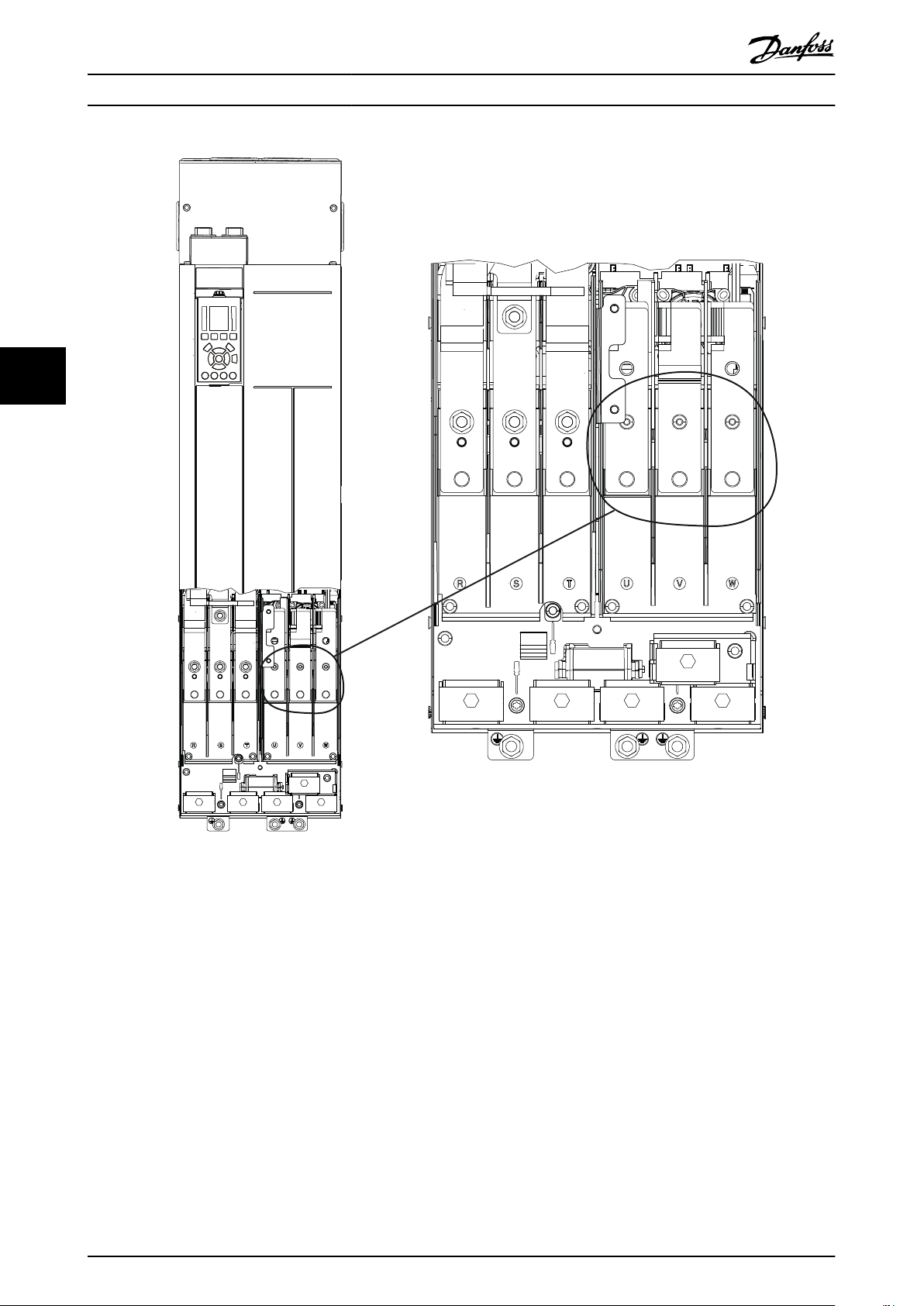
3.3 Interior View of J8 Drive
Illustration 3.1 shows the J8 components relevant to installation and commissioning.
3 3
1 Regen terminals 6 Mounting hole
2 LCP (local control panel) 7 Relays 1 and 2
3 Control terminals 8 Motor output terminals 96 (U), 97 (V), 98 (W)
4 Mains input terminals 91 (L1), 92 (L2), 93 (L3) 9 Cable clamps
5 Lifting ring 10 Ground terminals
Illustration 3.1 Interior View of J8 Drive
MG06I102 Danfoss A/S © 06/2018 All rights reserved. 7
Page 10

2
3
1
4
5
7
8
9
10
e30bg479.10
6
Product Overview VLT® AutomationDrive FC 361
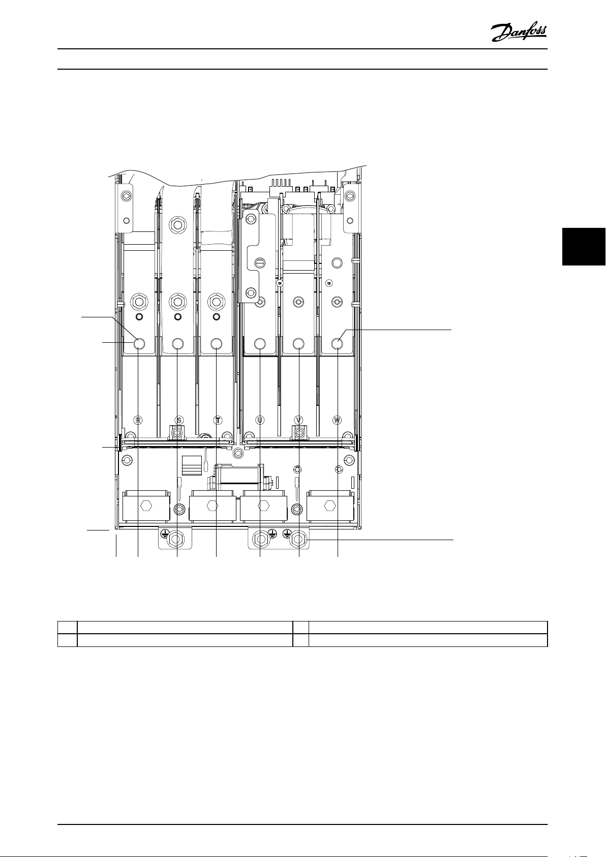
3.4 Interior View of J9 Drive
Illustration 3.2 shows the J9 components relevant to installation and commissioning.
33
1 Regen terminals 6 Cable clamps
2 Mounting hole 7 Top fan
3 LCP (local control panel) 8 Relays 1 and 2
4 Control terminals 9 Motor output terminals 96 (U), 97 (V), 98 (W)
5 Mains input terminals 91 (L1), 92 (L2), 93 (L3) 10 Ground terminals
Illustration 3.2 Interior View of J9 Drive
8 Danfoss A/S © 06/2018 All rights reserved. MG06I102
Page 11

2
4
10
3
9
11
12
6
7
e30bg270.10
5
1
8
Product Overview Operating Guide
3.5 View of Control Shelf
The control shelf holds the keypad, known as the local control panel or LCP. The control shelf also includes the control
terminals, relays, and various connectors.
3 3
1 Local control panel (LCP) 7 Mounting holes
2 RS485 termination switch 8 LCP connector
3 USB connector 9 Analog switches (A53, A54)
4 RS485 eldbus connector 10 Analog I/O connector
5 Digital I/O and 24 V supply 11 Relay 1 (01, 02, 03) on power card
6 Lifting rings 12 Relay 2 (04, 05, 06) on power card
Illustration 3.3 View of Control Shelf
MG06I102 Danfoss A/S © 06/2018 All rights reserved. 9
Page 12

130BF155.11
Auto
On
Reset
Hand
On
Off
Status
Quick
Menu
Main
Menu
Alarm
Log
Back
Cancel
Info
OK
Status
1(1)
0.00 kW
Off Remote Stop
0.0 Hz
On
Alarm
Warn.
0.00 A
0 RPM
0.0 %
A1.1
A1.2
A1.3
A2
A3
B1
B2
B4
B3
C1
C2
C3
C4
C5
D1
D2
D3
E1
E2
E3
E4
Product Overview VLT® AutomationDrive FC 361
3.6 Local Control Panel (LCP)
The local control panel (LCP) is the combined display and keypad on the front of the drive.
The LCP is used to:
Control the drive and motor.
33
•
Access drive parameters and program the drive.
•
Display operational data, drive status, and warnings.
•
A numeric local control panel (NLCP) is available as an option. The NLCP operates in a manner similar to the LCP, but there
are
dierences. For details on how to use the NLCP, see the product-specic programming guide.
Illustration 3.4 Local Control Panel (LCP)
A. Display area
Each display readout has a parameter associated with it. See Table 3.2. The information shown on the LCP can be
customized for specic applications. Refer to chapter 3.7.1.2 Q1 My Personal Menu.
Table 3.2 LCP Display Area
10 Danfoss A/S © 06/2018 All rights reserved. MG06I102
Callout Parameter Default setting
A1.1 Parameter 0-20 Display Line 1.1 Small Speed [RPM]
A1.2 Parameter 0-21 Display Line 1.2 Small Motor current [A]
A1.3 Parameter 0-22 Display Line 1.3 Small Power [kW ]
A2 Parameter 0-23 Display Line 2 Large Frequency [Hz]
A3 Parameter 0-24 Display Line 3 Large kWh counter
Page 13

Product Overview Operating Guide
B. Menu keys
Menu keys are used to access the menus for setting up
parameters, toggling through status display modes during
normal operation, and viewing fault log data.
Callout Key Function
B1 Status Shows operational information.
B2 Quick Menu Allows access to parameters for initial
set-up instructions. Also provides
detailed application steps. Refer
to chapter 3.7.1.1 Quick Menu Mode.
B3 Main Menu Allows access to all parameters. Refer to
chapter 3.7.1.6 Main Menu Mode.
B4 Alarm Log Shows a list of current warnings and the
last 10 alarms.
Table 3.3 LCP Menu Keys
C. Navigation keys
Navigation keys are used for programming functions and
moving the display cursor. The navigation keys also
provide speed control in local (hand) operation. The
display brightness can be adjusted by pressing [Status] and
[▲]/[▼] keys.
Callout Key Function
C1 Back Reverts to the previous step or list in the
menu structure.
C2 Cancel Cancels the last change or command as
long as the display mode has not changed.
C3 Info Shows a denition of the selected function.
C4 OK Accesses parameter groups or enables an
option.
C5
▲ ▼
Table 3.4 LCP Navigation Keys
Moves between items in the menu.
◄ ►
D. Indicator lights
Indicator lights are used to identify the drive status and to
provide a visual notication of warning or fault conditions.
Callout Indicator Indicator
D1 On Green Lights when the drive receives
D2 Warn. Yellow Lights when warning conditions
D3 Alarm Red Lights during a fault condition.
Table 3.5 LCP Indicator Lights
Function
light
power from the mains voltage or
a 24 V external supply.
are active. Text appears in the
display area identifying the
problem.
Text appears in the display area
identifying the problem.
E. Operation keys and reset
The operation keys are found toward the bottom of the
local control panel.
Callout Key Function
E1 Hand On Starts the drive in local control. An
external stop signal by control input or
serial communication overrides the local
[Hand On].
E2 O Stops the motor but does not remove
power to the drive.
E3 Auto On Puts the system in remote operational
mode so it can respond to an external
start command by control terminals or
serial communication.
E4 Reset Resets the drive manually after a fault has
been cleared.
3 3
Table 3.6 LCP Operation Keys and Reset
MG06I102 Danfoss A/S © 06/2018 All rights reserved. 11
Page 14

Q1 My Personal Menu
Q2 Quick Setup
Q5 Changes Made
Q6 Loggings
0 RPM 0.00 A
Quick Menus
1(1)
e30bg272.10
O-** Operation / Display
1-** Load and Motor
2-** Brakes
3-** Reference / Ramps
0 RPM 0.00 A
Main Menu
1(1)
Product Overview VLT® AutomationDrive FC 361
3.7 LCP Menus
3.7.1.1 Quick Menu Mode
The Quick Menu mode provides a list of menus used to
congure and operate the drive. Select the Quick Menu
33
mode by pressing the [Quick Menu] key. The resulting
readout appears on the LCP display.
Illustration 3.5 Quick Menu View
3.7.1.2 Q1 My Personal Menu
Use My Personal Menu to determine what is shown in the
display area. Refer to chapter 3.6 Local Control Panel (LCP).
This menu can also show up to 50 pre-programmed
parameters. These 50 parameters are manually entered
using parameter 0-25 My Personal Menu.
3.7.1.5 Q6 Loggings
Use Q6 Loggings for fault nding. To get information about
the display line readout, select Loggings. The information is
shown as graphs. Only parameters selected in
parameter 0-20 Display Line 1.1 Small through
parameter 0-24 Display Line 3 Large can be viewed. It is
possible to store up to 120 samples in the memory for
later reference.
Q6 Loggings
Parameter 0-20 Display Line 1.1 Small Speed [RPM]
Parameter 0-21 Display Line 1.2 Small Motor Current
Parameter 0-22 Display Line 1.3 Small Power [kW]
Parameter 0-23 Display Line 2 Large Frequency
Parameter 0-24 Display Line 3 Large Reference %
Table 3.7 Logging Parameter Examples
3.7.1.6 Main Menu Mode
The Main Menu mode lists all the parameter groups
available to the drive. Select the Main Menu mode by
pressing the [Main Menu] key. The resulting readout
appears on the LCP display.
3.7.1.3 Q2 Quick Setup
The parameters found in the Q2 Quick Setup contain basic
system and motor data that are always necessary for
conguring the drive. See chapter 7.2.3 Entering System
Information for the set-up procedures.
3.7.1.4 Q5 Changes Made
Select Q5 Changes Made for information about:
The 10 most recent changes.
•
Changes made from default setting.
•
Illustration 3.6 Main Menu View
All parameters can be changed in the main menu. Option
cards added to the unit enable extra parameters associated
with the option device.
12 Danfoss A/S © 06/2018 All rights reserved. MG06I102
Page 15

OUT: 3x0-Vin 0-590Hz 212/190 A
IN: 3x380-480 V 50/60Hz 204/183 A
110 kW / 150 HP, High Overload
OUT: 3x0-Vir. 0-590Hz 260/240 A
132 kW / 200 HP, Normal Overload
VLT
T/C: FC-361N132T4E20H2RXCXXXSXXXXAXBX
P/N: 136G8270 S/N:
123456H123
R
AutomationDrive
www.danfoss.com
e30bg567.10
IN: 3x380-480V 50/60Hz 251/231 A
ASSEMBLED IN USA
Max Tamb. 55
C/131
F w/Output Current Derating
CHASSIS/IP20 Tamb. 45 C/113 F
CAUTION - ATTENTION:
Stored charge, wait 20 min.
Charge residuelle, attendez 20 min.
See manual for special condition / mains fuse
Voir manuel de conditions speciales / fusibles
WARNING - AVERTISSEMENT:
`
`
1
2
3
4
5
6
Danfoss A/S
6340 Nordborg
Denmark
Mechanical Installation Operating Guide
4 Mechanical Installation
4.1 Items Supplied
Items supplied may vary according to product congu-
ration.
Make sure the items supplied and the information
•
on the nameplate correspond to the order conrmation.
Check the packaging and the drive visually for
•
damage caused by inappropriate handling during
shipment. File any claim for damage with the
carrier. Retain damaged parts for clarication.
4.2 Tools Needed
Receiving/unloading
I-beam and hooks rated to lift the weight of the
•
drive. Refer to chapter 3.2 Power Ratings, Weights,
and Dimensions.
Crane or other lifting aid to place the unit into
•
position.
Installation
Drill with 10 mm (0.39 in) or 12 mm (0.47 in) drill
•
bits.
Tape measurer.
•
Various sizes of Phillips and at bladed
•
screwdrivers.
Wrench with relevant metric sockets (7–17 mm/
•
0.28–0.67 in).
Wrench extensions.
•
Torx drives (T25 and T50).
•
Sheet metal punch for conduits or cable glands.
•
I-beam and hooks to lift the weight of the drive.
•
Refer to chapter 3.2 Power Ratings, Weights, and
Dimensions.
Crane or other lifting aid to place the drive onto
•
pedestal and into position.
4 4
Storage
4.3
Store the drive in a dry location. Keep the equipment
sealed in its packaging until installation. Refer to
1 Type code
2 Part number and serial number
3 Power rating
4 Input voltage, frequency, and current
5 Output voltage, frequency, and current
6 Discharge time
Illustration 4.1 Example Nameplate for Drive Only (J8–J9)
NOTICE
LOSS OF WARRANTY
Do not remove the nameplate from the drive. Removing
the nameplate can result in loss of warranty.
MG06I102 Danfoss A/S © 06/2018 All rights reserved. 13
chapter 10.4 Ambient Conditions for recommended ambient
temperature.
Periodic forming (capacitor charging) is not necessary
during storage unless storage exceeds 12 months.
Operating Environment
4.4
NOTICE
In environments with airborne liquids, particles, or
corrosive gases, ensure that the IP/type rating of the
equipment matches the installation environment. Failure
to meet requirements for ambient conditions can reduce
the lifetime of the drive. Ensure that requirements for air
humidity, temperature, and altitude are met.
Voltage [V] Altitude restrictions
380–480 At altitudes above 3000 m (9842 ft), contact
Danfoss regarding PELV.
Table 4.1 Installation at High Altitudes
Page 16

Mechanical Installation VLT® AutomationDrive FC 361
For detailed ambient conditions specications, refer to
chapter 10.4 Ambient Conditions.
can accumulate on fan blades causing an imbalance which
prevents the fans from properly cooling the unit.
NOTICE
CONDENSATION
Moisture can condense on the electronic components
and cause short circuits. Avoid installation in areas
subject to frost. Install an optional space heater when
the drive is colder than the ambient air. Operating in
44
standby mode reduces the risk of condensation as long
as the power dissipation keeps the circuitry free of
moisture.
NOTICE
EXTREME AMBIENT CONDITIONS
Hot or cold temperatures compromise unit performance
and longevity.
Do not operate in environments where the
•
ambient temperature exceeds 55 °C (131 °F).
The drive can operate at temperatures down to
•
-10 °C (14 °F). However, proper operation at
rated load is only guaranteed at 0 °C (32 °F) or
higher.
If temperature exceeds ambient temperature
•
limits, extra air conditioning of the cabinet or
installation site is required.
4.4.1 Gases
Aggressive gases, such as hydrogen sulde, chlorine, or
ammonia can damage the electrical and mechanical
components. The unit uses conformal-coated circuit boards
to reduce the eects of aggressive gases. For conformalcoating class specications and ratings, see
chapter 10.4 Ambient Conditions.
4.4.2 Dust
When installing the drive in dusty environments, pay
attention to the following:
Periodic maintenance
When dust accumulates on electronic components, it acts
as a layer of insulation. This layer reduces the cooling
capacity of the components, and the components become
warmer. The hotter environment decreases the life of the
electronic components.
Keep the heat sink and fans free from dust buildup. For
more service and maintenance information, refer to
chapter 9 Maintenance, Diagnostics, and Troubleshooting.
Cooling fans
Fans provide
exposed to dusty environments, the dust can damage the
fan bearings and cause premature fan failure. Also, dust
airow to cool the drive. When fans are
4.4.3 Potentially Explosive Atmospheres
WARNING
EXPLOSIVE ATMOSPHERE
Do not install the drive in a potentially explosive
atmosphere. Install the unit in a cabinet outside of this
area. Failure to follow this guideline increases risk of
death or serious injury.
4.5 Installation and Cooling Requirements
NOTICE
MOUNTING PRECAUTIONS
Improper mounting can result in overheating and
reduced performance. Observe all installation and
cooling requirements.
Installation Requirements
Ensure unit stability by mounting vertically to a
•
solid at surface.
Ensure that the strength of the mounting location
•
supports the unit weight. Refer to
chapter 3.2 Power Ratings, Weights, and
Dimensions.
Ensure the mounting location allows access to
•
open the enclosure door. See
chapter 10.9 Enclosure Dimensions.
Ensure that there is adequate space around the
•
unit for cooling airow.
Place the unit as near to the motor as possible.
•
Keep the motor cables as short as possible. See
chapter 10.5 Cable Specications.
Ensure the location allows for cable entry at the
•
bottom of the unit.
Cooling and Airow Requirements
Ensure that top and bottom clearance for air
•
cooling is provided. Clearance requirement:
225 mm (9 in).
Consider derating for temperatures starting
•
between 45 °C (113 °F) and 50 °C (122 °F) and
elevation 1000 m (3300 ft) above sea level. See
the product-specic design guide for detailed
information.
14 Danfoss A/S © 06/2018 All rights reserved. MG06I102
Page 17

65° min
e30bg512.10
Mechanical Installation Operating Guide
The drive uses back-channel cooling to circulate the heat
sink cooling air. The cooling duct can carries approximately
90% of the heat out of the back channel of the drive.
Redirect the back-channel air from the panel or room by
using:
Duct cooling. Back-channel cooling kits are
•
available to direct the air away from the panel
when an IP20/chassis drive is installed in a Rittal
enclosure. Use of a kit reduces the heat in the
panel and smaller door fans can be specied on
the enclosure.
Cooling out the back (top and base covers). The
•
back-channel cooling air can be ventilated out of
the room so that the heat from the back channel
is not dissipated into the control room.
NOTICE
One or more door fans are required on the enclosure to
remove heat not contained in the back channel of the
drive. The fans also remove any additional losses
generated by other components inside the drive.
Ensure that the fans supply adequate airow over the heat
sink. To select the appropriate number of fans, calculate
the total required airow. The ow rate is shown in
Table 4.2.
Enclosure size Door fan/top fan Heat sink fan
J8
J9
102 m3/hr (60 CFM) 420 m3/hr (250 CFM)
204 m3/hr (120 CFM) 840 m3/hr (500 CFM)
Lifting the Drive
4.6
Always lift the drive using the dedicated eye bolts at the
top of the drive. See Illustration 4.2.
WARNING
HEAVY LOAD
Unbalanced loads can fall or tip over. Failure to take
proper lifting precautions increases risk of death, serious
injury, or equipment damage.
Move the unit using a hoist, crane, forklift, or
•
other lifting device with the appropriate weight
rating. See chapter 3.2 Power Ratings, Weights,
and Dimensions for the weight of the drive.
Failure to locate the center of gravity and
•
correctly position the load can cause
unexpected shifting during lifting and
transport. For measurements and center of
gravity, see chapter 10.9 Enclosure Dimensions.
The angle from the top of the drive module to
•
the lifting cables aects the maximum load
force on the cable. This angle must be 65° or
greater. Refer to Illustration 4.2. Attach and
dimension the lifting cables properly.
Never walk under suspended loads.
•
To guard against injury, wear personal
•
protective equipment such as gloves, safety
glasses, and safety shoes.
4 4
Table 4.2 Airow
Illustration 4.2 Lifting the Drive
MG06I102 Danfoss A/S © 06/2018 All rights reserved. 15
Page 18

1
2
e30bg288.10
1
130BF662.10
2
Mechanical Installation VLT® AutomationDrive FC 361
4.7 Mounting the Drive
Wall mounting
J8 and J9 are chassis drives intended to be mounted on a
wall or on a mounting plate within an enclosure. To wall
mount a drive, use the following steps. Refer to
Illustration 4.3.
1. Fasten 2 M10 bolts in the wall to align with the
44
fastener slots at the bottom of drive.
2. Slide the lower fastener slots in the drive over the
M10 bolts.
3. Tip the drive against the wall, and secure the top
with 2 M10 bolts in the mounting holes.
Creating cable openings
After installing the drive, create cable openings in the
gland plate to accommodate the mains and motor cables.
The gland plate is required to maintain the drive
protection rating.
Punch out plastic tabs to accommodate the
•
cables. See Illustration 4.4.
1 Plastic tabs
2 Tabs removed for cable access
Illustration 4.4 Cable Openings in Plastic Gland Plate
1 Top mounting holes
2 Lower fastener slots
Illustration 4.3 Drive-to-wall Mounting Holes
16 Danfoss A/S © 06/2018 All rights reserved. MG06I102
Page 19

Electrical Installation Operating Guide
5 Electrical Installation
5.1 Safety Instructions
See chapter 2 Safety for general safety instructions.
WARNING
INDUCED VOLTAGE
Induced voltage from output motor cables from dierent
drives that are run together can charge equipment
capacitors even with the equipment turned o and
locked out. Failure to run output motor cables separately
or use shielded cables could result in death or serious
injury.
Run output motor cables separately or use
•
shielded cables.
Simultaneously lock out all the drives.
•
WARNING
SHOCK HAZARD
The drive can cause a DC current in the ground
conductor and thus result in death or serious injury.
When a residual current-operated protective
•
device (RCD) is used for protection against
electrical shock, only an RCD of Type B is
allowed on the supply side.
Failure to follow the recommendation means that the
RCD cannot provide the intended protection.
CAUTION
PROPERTY DAMAGE
Protection against motor overload is not included in the
default setting. To add this function, set
parameter 1-90 Motor Thermal Protection to [ETR trip] or
[ETR warning]. For the North American market, the ETR
function provides class 20 motor overload protection in
accordance with NEC. Failure to set parameter 1-90 Motor
Thermal Protection to [ETR trip] or [ETR warning] means
that motor overload protection is not provided and, if
the motor overheats, property damage can occur.
5.2 EMC-compliant Installation
To obtain an EMC-compliant installation, follow the
instructions provided in:
chapter 5.3 Wiring Schematic.
•
chapter 5.4 Connecting to Ground.
•
chapter 5.5 Connecting the Motor.
•
chapter 5.6 Connecting the AC Mains.
•
NOTICE
TWISTED SHIELD ENDS (PIGTAILS)
Twisted shield ends (pigtails) increase the shield
impedance at higher frequencies, reducing the shield
eect and increasing the leakage current. To avoid
twisted shield ends, use integrated shield clamps.
5 5
Overcurrent protection
Additional protective equipment such as short-
•
circuit protection or motor thermal protection
between drive and motor is required for
applications with multiple motors.
Input fusing is required to provide short circuit
•
and overcurrent protection. If fuses are not
factory-supplied, the installer must provide them.
See maximum fuse ratings in chapter 10.7 Fuses
and Circuit Breakers.
Wire type and ratings
All wiring must comply with local and national
•
regulations regarding cross-section and ambient
temperature requirements.
Power connection wire recommendation:
•
Minimum 75 °C (167 °F) rated copper wire.
See chapter 10.5 Cable Specications for recommended wire
sizes and types.
For use with relays, control cables, a signal
•
interface, eldbus, or brake, connect the shield to
the enclosure at both ends. If the ground path
has high impedance, is noisy, or is carrying
current, break the shield connection on 1 end to
avoid ground current loops.
Convey the currents back to the unit using a
•
metal mounting plate. Ensure good electrical
contact from the mounting plate through the
mounting screws to the drive chassis.
Use shielded cables for motor output cables. An
•
alternative is unshielded motor cables within
metal conduit.
NOTICE
SHIELDED CABLES
If shielded cables or metal conduits are not used, the
unit and the installation do not meet regulatory limits
on radio frequency (RF) emission levels.
MG06I102 Danfoss A/S © 06/2018 All rights reserved. 17
Page 20

Electrical Installation VLT® AutomationDrive FC 361
Ensure that motor and brake cables are as short
•
as possible to reduce the interference level from
the entire system.
Avoid placing cables with a sensitive signal level
•
alongside motor and brake cables.
For communication and command/control lines,
•
follow the particular communication protocol
standards. For example, USB must use shielded
cables, but RS485/ethernet can use shielded UTP
or unshielded UTP cables.
Ensure that all control terminal connections are
•
55
PELV.
NOTICE
EMC INTERFERENCE
Use shielded cables for motor and control wiring, and
separate cables for mains input, motor wiring, and
control wiring. Failure to isolate power, motor, and
control cables can result in unintended behavior or
reduced performance. Minimum 200 mm (7.9 in)
clearance between mains input, motor, and control
cables are required.
NOTICE
INSTALLATION AT HIGH ALTITUDE
There is a risk for overvoltage. Isolation between
components and critical parts could be insucient, and
not comply with PELV requirements. Reduce the risk for
overvoltage by using external protective devices or
galvanic isolation.
For installations above 2000 m (6500 ft) altitude, contact
Danfoss regarding PELV compliance.
NOTICE
PELV COMPLIANCE
Prevent electric shock by using protective extra low
voltage (PELV) electrical supply and complying with local
and national PELV regulations.
18 Danfoss A/S © 06/2018 All rights reserved. MG06I102
Page 21

e30bf228.11
L1
L2
L3
PE
PE
u
v
w
2
1
3
5
16
17
18
14
12
8
7
10
9
4
11
13
4
6
15
90
4
Electrical Installation Operating Guide
5 5
1 PLC 10 Mains cable (unshielded)
2
Minimum 16 mm2 (6 AWG) equalizing cable
3 Control cables 12 Cable insulation stripped
4 Required minimum separation of 200 mm (7.9 in) between
control cables, motor cables, and mains cables
5 Mains supply 14 Brake resistor
6 Bare (unpainted) surface 15 Metal box
7 Star washers 16 Connection to motor
8 Brake cable (shielded) 17 Motor
9 Motor cable (shielded) 18 EMC cable gland
Illustration 5.1 Example of Proper EMC Installation
11 Output contactor and similar options
13 Common ground busbar (Follow local and national
requirements for enclosure grounding)
MG06I102 Danfoss A/S © 06/2018 All rights reserved. 19
Page 22

e30bg500.10
Regen +
Regen -
83
Regen
91 (L1)
92 (L2)
93 (L3)
PE
50 (+10 V OUT)
53 (A IN)
54 (A IN)
55 (COM A IN)
0/4-20 mA
12 (+24 V OUT)
13 (+24 V OUT)
18 (D IN)
20
(COM D IN)
15 mA
200 mA
(U) 96
(V) 97
(W) 98
(PE) 99
(COM A OUT) 39
(A OUT) 42
0/4-20 mA
03
+10 V DC
0 to +10 V DC
0/4-20 mA
24 V DC
02
01
05
04
06
240 V AC, 2A
24 V (NPN)
0 V (PNP)
0 V (PNP)
24 V (NPN)
19 (D IN)
24 V (NPN)
0 V (PNP)
27
24V
0V
(D IN/OUT)
0 V (PNP)
24 V (NPN)
(D IN/OUT)
0V
24V
29
24 V (NPN)
0 V (PNP)
0 V (PNP)
24 V (NPN)
33 (D IN)
32 (D IN)
1
2
ON
A53 U-I (S201)
ON
2
1
A54 U-I (S202)
ON=0/4-20 mA
OFF=0 to ±10 V
95
400 V AC, 2A
P 5-00
(R+) 82
+-+
-
(P RS485) 68
(N RS485) 69
(COM RS485) 61
0V5VS801
RS485
RS485
2
1
ON
S801/Bus Term.
OFF-ON
3-phase
power
input
Switch mode
power supply
Motor
Analog output
interface
Relay1
Relay2
ON=Terminated
OFF=Open
(NPN) = Sink
(PNP) = Source
240 V AC, 2A
400 V AC, 2A
0 to +10 V DC
10 V DC
Electrical Installation VLT® AutomationDrive FC 361
5.3 Wiring Schematic
55
Illustration 5.2 Basic Wiring Schematic
20 Danfoss A/S © 06/2018 All rights reserved. MG06I102
Page 23

Electrical Installation Operating Guide
5.4 Connecting to Ground
WARNING
LEAKAGE CURRENT HAZARD
Leakage currents exceed 3.5 mA. Failure to ground the drive properly can result in death or serious injury.
Ensure the correct grounding of the equipment by a certied electrical installer.
•
For electrical safety
Ground the drive in accordance with applicable standards and directives.
•
Use a dedicated ground wire for input power, motor power, and control wiring.
•
Do not ground 1 drive to another in a daisy chain fashion.
•
Keep the ground wire connections as short as possible.
•
Follow motor manufacturer wiring requirements.
•
Minimum cable cross-section: 10 mm2 (6 AWG) (or 2 rated ground wires terminated separately).
•
Tighten the terminals in accordance with the information provided in chapter 10.8 Fastener Tightening Torques.
•
5 5
For EMC-compliant installation
Establish electrical contact between the cable shield and the drive enclosure by using metal cable glands or by
•
using the clamps provided on the equipment.
Reduce burst transient by using high-strand wire.
•
Do not use twisted shield ends (pigtails).
•
NOTICE
POTENTIAL EQUALIZATION
There is a risk of burst transient when the ground potential between the drive and the control system is dierent.
Install equalizing cables between the system components. Recommended cable cross-section: 16 mm2 (5 AWG).
MG06I102 Danfoss A/S © 06/2018 All rights reserved. 21
Page 24

e30bg480.10
Electrical Installation VLT® AutomationDrive FC 361
55
Illustration 5.3 Ground Terminals (J8 shown)
22 Danfoss A/S © 06/2018 All rights reserved. MG06I102
Page 25

Electrical Installation Operating Guide
5.5 Connecting the Motor
WARNING
INDUCED VOLTAGE
Induced voltage from output motor cables that run together can charge equipment capacitors, even with the
equipment turned o and locked out. Failure to run output motor cables separately or use shielded cables could result
in death or serious injury.
Comply with local and national electrical codes for cable sizes. For maximum wire sizes, see chapter 10.5 Cable
•
Specications.
Follow motor manufacturer wiring requirements.
•
Motor wiring knockouts or access panels are provided at the base of IP21 (NEMA1/12) and higher units.
•
Do not wire a starting or pole-changing device (for example Dahlander motor or slip ring asynchronous motor)
•
between the drive and the motor.
Procedure
1. Strip a section of the outer cable insulation.
2. Position the stripped wire under the cable clamp, establishing mechanical xation and electrical contact between
the cable shield and ground.
3. Connect the ground wire to the nearest grounding terminal in accordance with the grounding instructions
provided in chapter 5.4 Connecting to Ground, see Illustration 5.4.
4. Connect the 3-phase motor wiring to terminals 96 (U), 97 (V), and 98 (W), see Illustration 5.4.
5. Tighten the terminals in accordance with the information provided in chapter 10.8 Fastener Tightening Torques.
5 5
MG06I102 Danfoss A/S © 06/2018 All rights reserved. 23
Page 26
e30bg481.10
Electrical Installation VLT® AutomationDrive FC 361
55
Illustration 5.4 Motor Terminals (J8 shown)
24 Danfoss A/S © 06/2018 All rights reserved. MG06I102
Page 27

Electrical Installation Operating Guide
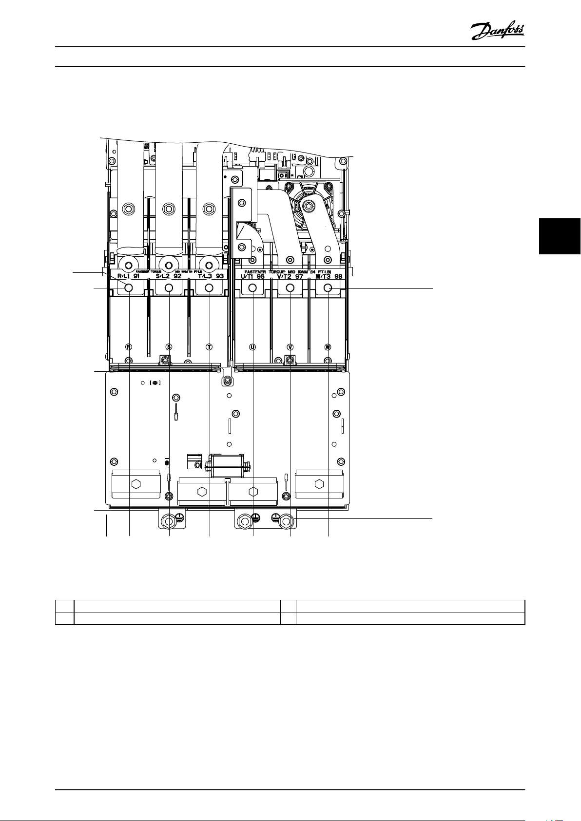
5.6 Connecting the AC Mains
Size the wiring according to the input current of the drive. For maximum wire sizes, see chapter 10.1 Electrical Data,
•
380-480 V.
Comply with local and national electrical codes for cable sizes.
•
Procedure
1. Strip a section of the outer cable insulation.
2. Position the stripped wire under the cable clamp, establishing mechanical xation and electrical contact between
the cable shield and ground.
3. Connect the ground wire to the nearest grounding terminal in accordance with the grounding instructions
provided in chapter 5.4 Connecting to Ground.
4. Connect the 3-phase AC input power wiring to terminals R, S, and T (see Illustration 5.5).
5. When supplied from an isolated mains source (IT mains or oating delta) or TT/TN-S mains with a grounded leg
(grounded delta), ensure that parameter 14-50 RFI Filter is set to [0] O to avoid damage to the DC link and to
reduce ground capacity currents.
6. Tighten the terminals in accordance with the information provided in chapter 10.8 Fastener Tightening Torques.
5 5
MG06I102 Danfoss A/S © 06/2018 All rights reserved. 25
Page 28

e30bg482.10
Electrical Installation VLT® AutomationDrive FC 361
55
Illustration 5.5 AC Mains Terminals (J8 shown). For a detailed view of terminals, see chapter 5.7 Terminal Dimensions.
26 Danfoss A/S © 06/2018 All rights reserved. MG06I102
Page 29
e30bg615.10
83 (3.3)
0.0
188 (7.4)
22 (0.9)
62 (2.4)
101 (4.0)
145 (5.7)
184 (7.2)
223 (8.8)
0.0
1
2
3
Electrical Installation Operating Guide
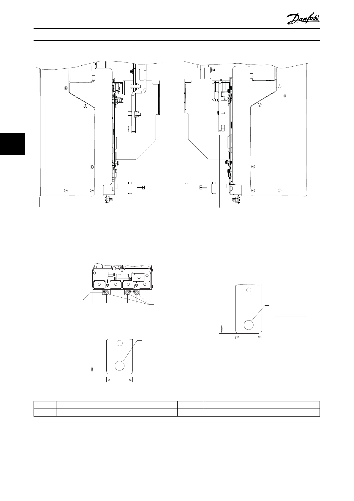
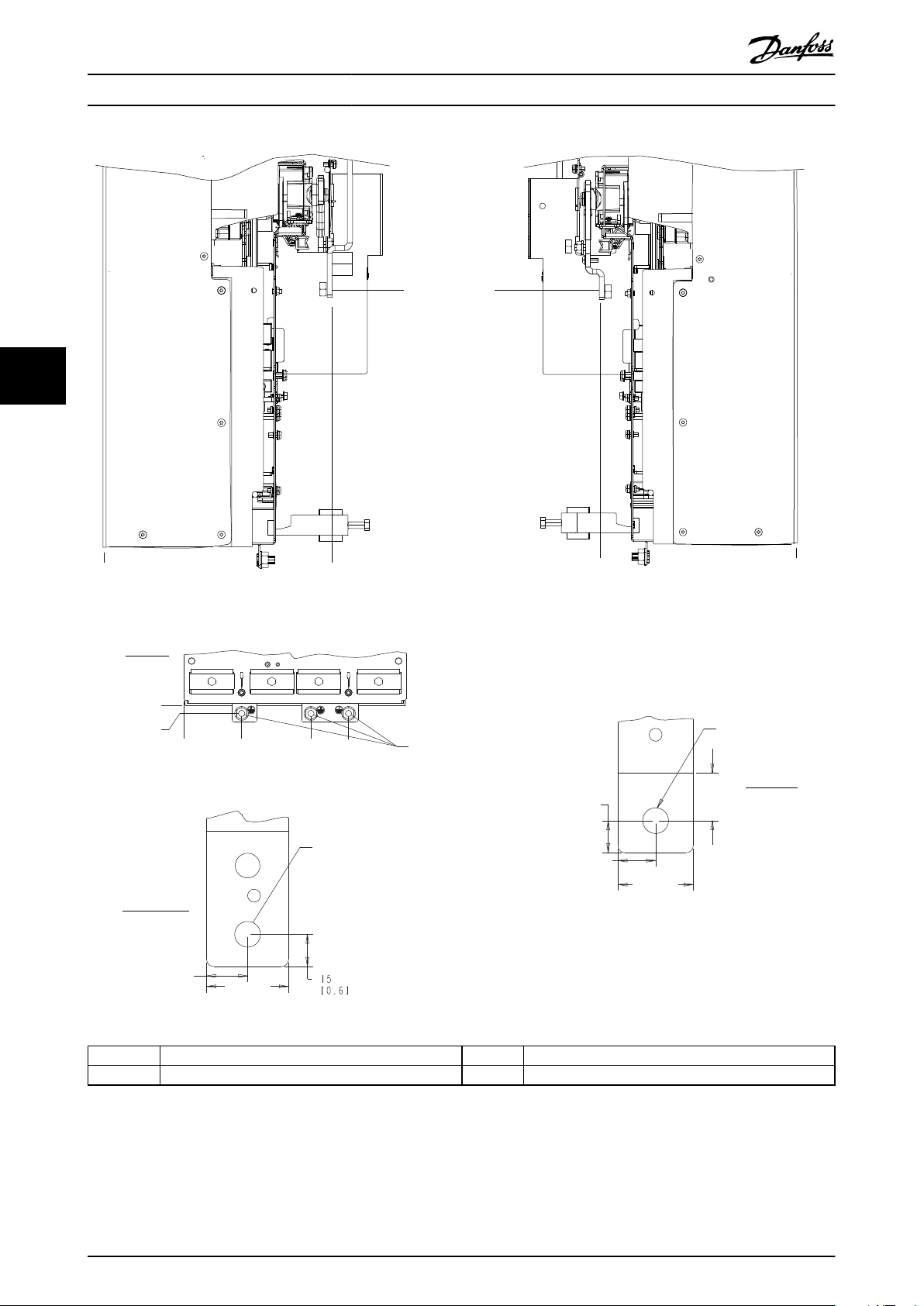
5.7 Terminal Dimensions
5.7.1 J8 Terminal Dimensions
5 5
1 Mains terminals 3 Ground terminals
2 Motor terminals
Illustration 5.6 J8 Terminal Dimensions (Front View)
MG06I102 Danfoss A/S © 06/2018 All rights reserved. 27
Page 30
M10
13 (0.5)
32 (1.3)
59 (2.3)
10 (0.4)
244 (9.6)
272 (10.7)
0.0
0.0
1
2
4
3
5
M10
13 (0.5)
32 (1.3)
145 (5.7)
182 (7.2)
3X M8x18
0
0
e30bg573.10
Electrical Installation VLT® AutomationDrive FC 361
55
1 and 4 Mains terminals 2 and 5 Motor terminals
3 Ground terminals
Illustration 5.7 J8 Terminal Dimensions (Side Views)
28 Danfoss A/S © 06/2018 All rights reserved. MG06I102
Page 31
33 (1.3)
91 (3.6)
149 (5.8)
211 (8.3)
265 (10.4)
319 (12.6)
200 (7.9)
319 (12.6)
e30bg616.10
0.0
o.o
1
2
3
Electrical Installation Operating Guide
5.7.2 J9 Terminal Dimensions
5 5
1 Mains terminals 3 Ground terminals
2 Motor terminals
Illustration 5.8 J9 Terminal Dimensions (Front View)
MG06I102 Danfoss A/S © 06/2018 All rights reserved. 29
Page 32
4
3
91 (3.6)
13 (0.5)
200 (7.9)
259 (10.2)
3X M10X20
0
0
M10
19 (0.8)
38 (1.5)
255 (10.0)
284 (11.2)
0.0
0.0
1
2
5
M10
22 (0.9)
35 (1.4)
15 (0.6)
18 (0.7)
e30bg574.10
Electrical Installation VLT® AutomationDrive FC 361
55
1 and 4 Mains terminals 2 and 5 Motor terminals
3 Ground terminals 4 Ground terminals
Illustration 5.9 J9 Terminal Dimensions (Side Views)
30 Danfoss A/S © 06/2018 All rights reserved. MG06I102
Page 33
e30bg501.10
12 13 18 19 27 29 32 33 20
39696861 42 50 53 54 55
e30bg502.10
1
2
3
Electrical Installation Operating Guide
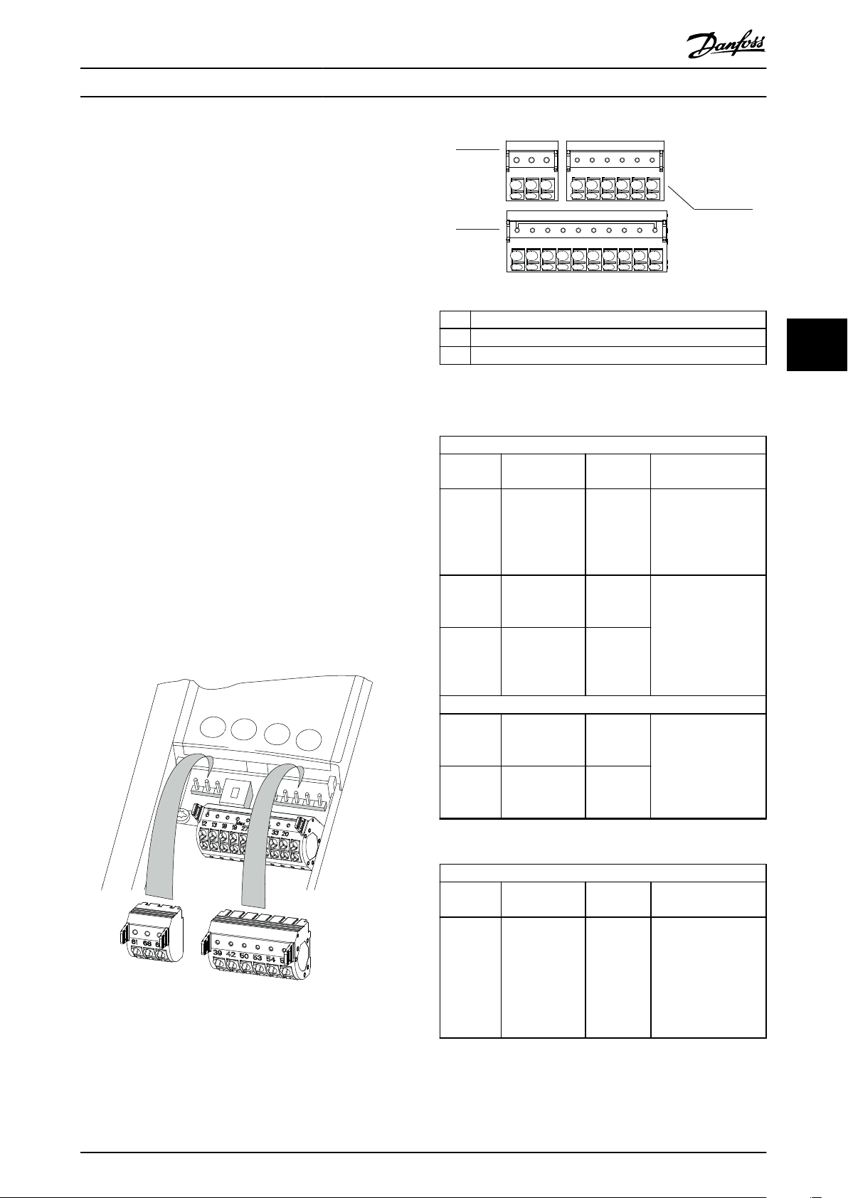
5.8 Control Wiring
All terminals to the control cables are inside the drive
below the LCP. To access the control terminals, remove the
front panel.
5.8.1 Control Cable Routing
Isolate control wiring from high-power
•
components in the drive.
Tie down all control wires after routing them.
•
Connect shields to ensure optimum electrical
•
immunity.
When the drive is connected to a thermistor,
•
ensure that the thermistor control wiring is
shielded and reinforced/double insulated. A 24 V
DC supply voltage is recommended.
Fieldbus connection
Connections are made to the relevant options on the
control card. For more detail, see the relevant eldbus
instruction. The cable must be tied down and routed along
with other control wires inside the unit.
5.8.2 Control Terminal Types
Illustration 5.10 shows the removable drive connectors.
Terminal functions and default settings are summarized in
Table 5.1 – Table 5.3.
1 Serial communication terminals
2 Digital input/output terminals
3 Analog input/output terminals
Illustration 5.11 Terminal Numbers Located on the Connectors
Serial communication terminals
Terminal Parameter Default
setting
61 – – Integrated RC-lter for
68 (+) Parameter
group 8-3* FC
Port Settings
69 (-) Parameter
group 8-3* FC
Port Settings
01, 02, 03 Parameter 5-40
Function Relay
[0]
04, 05, 06 Parameter 5-40
Function Relay
[1]
– RS485 interface. A
–
Relays
[0] No
operation
[0] No
operation
Description
cable shield. ONLY for
connecting the shield
in the event of EMC
problems.
switch (BUS TER.) is
provided on the
control card for bus
termination
resistance. See
Illustration 5.16.
Form C relay output.
For AC or DC voltage
and resistive or
inductive loads.
5 5
Table 5.1 Serial Communication Terminal Descriptions
Digital input/output terminals
Illustration 5.10 Control Terminal Locations
Terminal Parameter Default
setting
12, 13 – +24 V DC 24 V DC supply
Description
voltage for digital
inputs and external
transducers.
Maximum output
current 200 mA for all
24 V loads.
MG06I102 Danfoss A/S © 06/2018 All rights reserved. 31
Page 34
RELAY 1 RELAY 2
01 02 03 04 05 06
130BF156.10
Electrical Installation VLT® AutomationDrive FC 361
Digital input/output terminals
Terminal Parameter Default
setting
18 Parameter 5-10
Terminal 18
Digital Input
19 Parameter 5-11
Terminal 19
Digital Input
32 Parameter 5-14
Terminal 32
Digital Input
55
33 Parameter 5-15
Terminal 33
Digital Input
27 Parameter 5-12
Terminal 27
Digital Input
29 Parameter 5-13
Terminal 29
Digital Input
20 – – Common for digital
[8] Start Digital inputs.
[10]
Reversing
[0] No
operation
[0] No
operation
[2] Coast
inverse
[14] JOG
Description
For digital input or
output. Default
setting is input.
inputs and 0 V
potential for 24 V
supply.
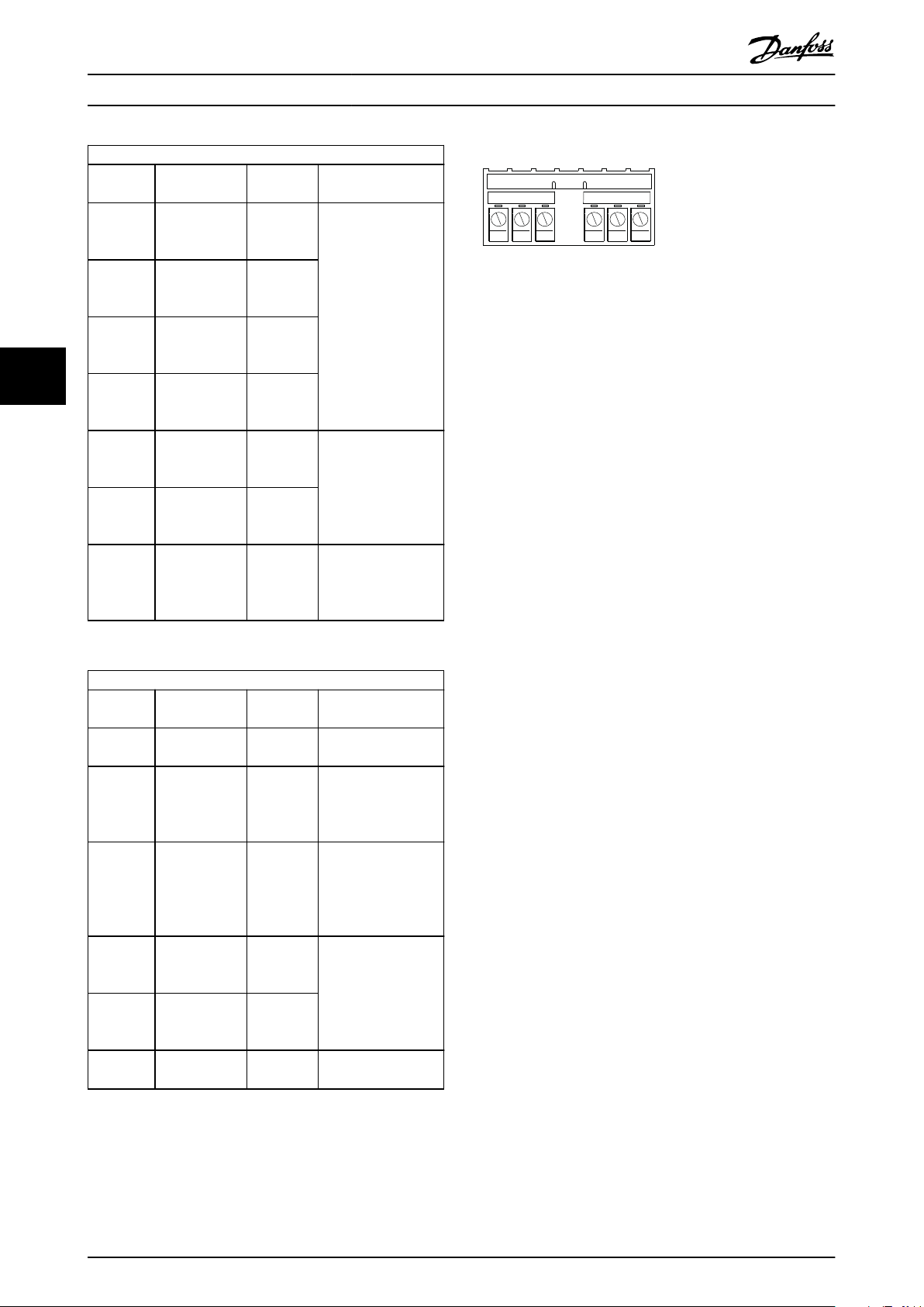
Relay terminals:
Illustration 5.12 Relay 1 and Relay 2 Terminals
Relay 1 and relay 2. The location of the outputs
•
depends on the drive conguration. See
chapter 3.5 View of Control Shelf.
Terminals on built-in optional equipment. See the
•
manual provided with the equipment option.
Table 5.2 Digital Input/Output Terminal Descriptions
Analog input/output terminals
Terminal Parameter Default
setting
39 – – Common for analog
42 Parameter 6-50
Terminal 42
Output
50 – +10 V DC 10 V DC analog
53 Parameter
group 6-1*
Analog Input 1
54 Parameter
group 6-2*
Analog Input 2
55 – – Common for analog
[0] No
operation
Reference Analog input. For
Feedback
Description
output.
Programmable analog
output. 0–20 mA or
4–20 mA at a
maximum of 500 Ω.
supply voltage for
potentiometer or
thermistor. 15 mA
maximum.
voltage or current.
Switches A53 and
A54 select mA or V.
input.
Table 5.3 Analog Input/Output Terminal Descriptions
32 Danfoss A/S © 06/2018 All rights reserved. MG06I102
Page 35
e30bg283.10
10 mm (0.4)
12 13 18 19 27 29 32 33
130BD546.11
2
1
12 13 18 19 27 29 32 33
10 mm (0.4)
Electrical Installation Operating Guide
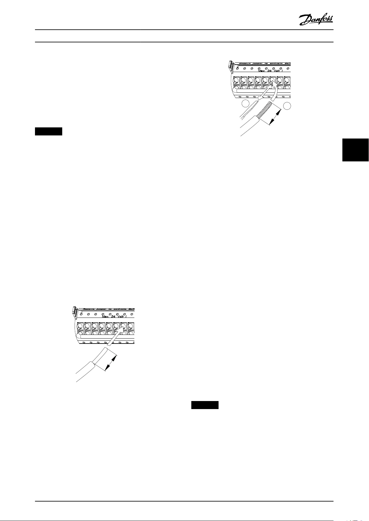
5.8.3 Wiring to Control Terminals
The control terminals are located near the LCP. The control
terminal connectors can be unplugged from the drive for
convenience when wiring, as shown in Illustration 5.10.
Either solid or exible wire can be connected to the
control terminals. Use the following procedures to connect
or disconnect the control wires.
NOTICE
Minimize interference by keeping control wires as short
as possible and separate from high-power cables.
Illustration 5.14 Connecting Flexible Control Wires
5 5
Connecting wire to control terminals
1. Strip 10 mm (0.4 in) of the outer plastic layer
from the end of the wire.
2. Insert the control wire into the terminal.
For a solid wire, push the bare wire into
•
the contact. See Illustration 5.13.
For a exible wire, open the contact by
•
inserting a small screwdriver into the
slot between the terminal holes and
push the screwdriver inward. See
Illustration 5.14. Then, insert the stripped
wire into the contact, and remove the
screwdriver.
3. Pull gently on the wire to ensure that the contact
is rmly established. Loose control wiring can be
the source of equipment faults or reduced
performance.
Illustration 5.13 Connecting Solid Control Wires
Disconnecting wires from the control terminals
1. To open the contact, insert a small screwdriver
into the slot between the terminal holes and
push the screwdriver inward.
2. Pull gently on the wire to free it from the control
terminal contact.
See chapter 10.5 Cable Specications for control terminal
wiring sizes and chapter 8 Wiring Conguration Examples for
typical control wiring connections.
5.8.4 Enabling Motor Operation
(Terminal 27)
A jumper wire is required between terminal 12 (or 13) and
terminal 27 for the drive to operate when using factory
default programming values.
Digital input terminal 27 is designed to receive
•
24 V DC external interlock command.
When no interlock device is used, wire a jumper
•
between control terminal 12 (recommended) or
13 to terminal 27. This wire provides an internal
24 V signal on terminal 27.
When the status line at the bottom of the LCP
•
reads AUTO REMOTE COAST, the unit is ready to
operate, but is missing an input signal on
terminal 27.
When factory-installed optional equipment is
•
wired to terminal 27, do not remove that wiring.
MG06I102 Danfoss A/S © 06/2018 All rights reserved. 33
NOTICE
The drive cannot operate without a signal on terminal
27, unless terminal 27 is reprogrammed using
parameter 5-12 Terminal 27 Digital Input.
Page 36

61
68
69
+
130BB489.10
RS485
130BF146.10
BUS TER.
OFF-ON
A53 A54
U- I U- I
1
2
N O
1
2
N O
1
2
N O
1
2
N O
Electrical Installation VLT® AutomationDrive FC 361
5.8.5 Conguring RS485 Serial
Communication
RS485 is a 2-wire bus interface compatible with multi-drop
network topology, and it contains the following features:
Either Danfoss FC or Modbus RTU communication
•
protocol, which are internal to the drive, can be
used.
Functions can be programmed remotely using
•
the protocol software and RS485 connection or in
parameter group 8-** Communications and
55
Options.
Selecting a specic communication protocol
•
changes various default parameter settings to
match the specications of the protocol, making
5.8.6 Selecting Voltage/Current Input
Signal
The analog input terminals 53 and 54 allow setting of
input signal to voltage (0–10 V) or current (0/4–20 mA).
Default parameter setting:
Terminal 53: Speed reference signal in open loop
•
(see parameter 16-61 Terminal 53 Switch Setting).
Terminal 54: Feedback signal in closed loop (see
•
parameter 16-63 Terminal 54 Switch Setting).
NOTICE
Disconnect power to the drive before changing switch
positions.
more protocol-specic parameters available.
1. Remove the LCP (local control panel).
Option cards for the drive are available to provide
•
See chapter 3.7 LCP Menus.
more communication protocols. See the option
card documentation for installation and operation
instructions.
A switch (BUS TER) is provided on the control
•
card for bus termination resistance. See
2. Remove any optional equipment covering the
switches.
3. Set switches A53 and A54 to select the signal
type (U = voltage, I = current).
Illustration 5.16.
For basic serial communication set-up, perform the
following steps:
1. Connect RS485 serial communication wiring to
terminals (+)68 and (-)69.
1a Use shielded serial communication cable
(recommended).
1b See chapter 5.4 Connecting to Ground for
proper grounding.
2. Select the following parameter settings:
2a Protocol type in parameter 8-30 Protocol.
2b Drive address in parameter 8-31 Address.
2c Baud rate in parameter 8-32 Baud Rate.
Illustration 5.16 Location of Terminal 53 and 54 Switches
Illustration 5.15 Serial Communication Wiring Diagram
34 Danfoss A/S © 06/2018 All rights reserved. MG06I102
Page 37

Pre-start Check List Operating Guide
6 Pre-start Check List
Before completing installation of the unit, inspect the entire installation as detailed in Table 6.1. Check and mark the items
when completed.
Inspect for Description
Motor
Switches
Auxiliary equipment•Look for auxiliary equipment, switches, disconnects, or input fuses/circuit breakers that reside on the input
Cable routing
Control wiring
Input and output
power wiring
Grounding
Fuses and circuit
breakers
Cooling clearance
Ambient conditions
Interior of Drive
Vibration
Conrm continuity of the motor by measuring ohm values on U–V (96–97), V–W (97–98), and W– U (98–
•
96).
Conrm that the supply voltage matches the voltage of the drive and the motor.
•
Ensure that all switch and disconnect settings are in the proper positions.
•
power side of the drive or output side to the motor. Ensure that they are ready for full-speed operation.
Check function and installation of any sensors used for feedback to the drive.
•
Remove any power factor correction caps on motor.
•
Adjust any power factor correction caps on the mains side and ensure that they are dampened.
•
Ensure that motor wiring, brake wiring (if equipped), and control wiring are separated or shielded, or in 3
•
separate metallic conduits for high-frequency interference isolation.
Check for broken or damaged wires and loose connections.
•
Check that control wiring is isolated from high-power wiring for noise immunity.
•
Check the voltage source of the signals, if necessary.
•
Use shielded cable or twisted pair and ensure that the shield is terminated correctly.
•
Check for loose connections.
•
Check that motor and mains are in separate conduit or separated shielded cables.
•
Check for good ground connections that are tight and free of oxidation.
•
Grounding to conduit, or mounting the back panel to a metal surface, is not a suitable grounding.
•
Check for proper fusing or circuit breakers.
•
Check that all fuses are inserted rmly and are in operational condition and that all circuit breakers (if
•
used) are in the open position.
Look for any obstructions in the airow path.
•
Measure top and bottom clearance of the drive to verify adequate airow for cooling, see
•
chapter 4.5 Installation and Cooling Requirements.
Check that requirements for ambient conditions are met. See chapter 10.4 Ambient Conditions.
•
Inspect that the unit interior is free of dirt, metal chips, moisture, and corrosion.
•
Verify that all installation tools have been removed from unit interior.
•
Ensure that the unit is mounted on an unpainted, metal surface.
•
Check that the unit is mounted solidly, or that shock mounts are used, if necessary.
•
Check for an unusual amount of vibration.
•
☑
6
6
Table 6.1 Pre-start Check List
MG06I102 Danfoss A/S © 06/2018 All rights reserved. 35
Page 38

Commissioning VLT® AutomationDrive FC 361
7 Commissioning
7.1 Applying Power
WARNING
UNINTENDED START
When the drive is connected to AC mains, DC supply, or
load sharing, the motor can start at any time, causing
risk of death, serious injury, and equipment, or property
damage. The motor can start by activation of an external
switch, a eldbus command, an input reference signal
from the LCP or LOP, via remote operation using MCT 10
Set-up software, or after a cleared fault.
To prevent unintended motor start:
Press [O] on the LCP before programming
•
77
NOTICE
MISSING SIGNAL
If the status at the bottom of the LCP reads AUTO
REMOTE COASTING, or alarm 60, External interlock is
shown, it indicates that the unit is ready to operate but
is missing an input signal on, for example, terminal 27.
See chapter 5.8.4 Enabling Motor Operation (Terminal 27).
parameters.
Disconnect the drive from mains whenever
•
personal safety considerations make it
necessary to avoid unintended motor start.
Check that the drive, motor, and any driven
•
equipment are in operational readiness.
Programming the Drive
7.2
7.2.1 Parameter Overview
Parameters contain various settings that are used to
congure and operate the drive and motor. These
parameter settings are programmed into the local control
panel (LCP) through the dierent LCP menus. For more
detail on parameters, see the product-specic programming
guide.
Parameter settings are assigned a default value at the
factory, but can be
Each parameter has a name and number that remain the
same regardless of the programming mode.
In the Main Menu mode, the parameters are divided into
groups. The rst digit of the parameter number (from the
left) indicates the parameter group number. The parameter
group is then broken down into sub groups, if necessary.
For example:
0-** Operation/Display Parameter group
0-0* Basic Settings Parameter sub
Parameter 0-01 Language Parameter
Parameter 0-02 Motor Speed Unit Parameter
Parameter 0-04 Operating State at Power-up
(Hand)
congured for their unique application.
group
Parameter
Apply power to the drive using the following steps:
1. Conrm that the input voltage is balanced within
3%. If not, correct the input voltage imbalance
before proceeding. Repeat this procedure after
the voltage correction.
2. Ensure that any optional equipment wiring
matches the installation requirements.
3. Ensure that all operator devices are in the OFF
position.
4. Close and securely fasten all covers and doors on
the drive.
5. Apply power to the unit, but do not start the
drive. For units with a disconnect switch, turn the
switch to the ON position to apply power to the
drive.
Table 7.1 Example of Parameter Group Hierarchy
7.2.2 Parameter Navigation
Use the following LCP keys to navigate through the
parameters:
Press [▲] [▼] to scroll up or down.
•
Press [◄] [►] to shift a space to the left or right of
•
a decimal point while editing a decimal
parameter value.
Press [OK] to accept the change.
•
Press [Cancel] to disregard the change and exit
•
edit mode.
Press [Back] twice to show the status view.
•
Press [Main Menu] once to go back to the main
•
menu.
36 Danfoss A/S © 06/2018 All rights reserved. MG06I102
Page 39
Commissioning Operating Guide
7.2.3 Entering System Information
NOTICE
SOFTWARE DOWNLOAD
For commissioning via PC, install MCT 10 Set-up
Software. The software is available for download (basic
version) or for ordering (advanced version, code number
130B1000). For more information and downloads, see
www.danfoss.com/en/service-and-support/downloads/dds/
vlt-motion-control-tool-mct-10/.
The following steps are used to enter basic system
information into the drive. Recommended parameter
settings are intended for start-up and checkout purposes.
Application settings vary.
NOTICE
Although these steps assume that an asynchronous
motor is used, a permanent magnet motor can be used.
For more information on specic motor types, see the
product-specic programming guide.
1. Press [Main Menu] on the LCP.
2. Select 0-** Operation/Display and press [OK].
3. Select 0-0* Basic Settings and press [OK].
4. Press [Quick Menus] on the LCP and then select
02 Quick Setup.
5. Change the following parameters settings listed
in Table 7.2 if necessary. The motor data is found
on the motor nameplate.
Parameter Default setting
Parameter 0-01 Language English
Parameter 1-20 Motor Power [kW ] 4.00 kW
Parameter 1-22 Motor Voltage 400 V
Parameter 1-23 Motor Frequency 50 Hz
Parameter 1-24 Motor Current 9.00 A
Parameter 1-25 Motor Nominal Speed 1420 RPM
Parameter 5-12 Terminal 27 Digital Input Coast inverse
Parameter 3-02 Minimum Reference 0.000 RPM
Parameter 3-03 Maximum Reference 1500.000 RPM
Parameter 3-41 Ramp 1 Ramp up Time 3.00 s
Parameter 3-42 Ramp 1 Ramp Down Time 3.00 s
Parameter 3-13 Reference Site Linked to Hand/
Auto
Parameter 1-29 Automatic Motor Adaptation
(AMA)
Table 7.2 Quick Set-up Settings
O
NOTICE
MISSING INPUT SIGNAL
When the LCP shows AUTO REMOTE COASTING or alarm
60, External Interlock, the unit is ready to operate but is
missing an input signal. See chapter 5.8.4 Enabling Motor
Operation (Terminal 27) for details.
7.2.4 Conguring Automatic Energy
Optimization
Automatic energy optimization (AEO) is a procedure that
minimizes voltage to the motor, reducing energy
consumption, heat, and noise.
1. Press [Main Menu].
2. Select 1-** Load and Motor and press [OK].
3. Select 1-0* General Settings and press [OK].
4. Select parameter 1-03 Torque Characteristics and
press [OK].
5. Select either [2] Auto Energy Optim CT or [3] Auto
Energy Optim VT and press [OK].
7.2.5 Conguring Automatic Motor
Adaptation
Automatic motor adaptation is a procedure that optimizes
compatibility between the drive and the motor.
The drive builds a mathematical model of the motor for
regulating output motor current. The procedure also tests
the input phase balance of electrical power. It compares
the motor characteristics with the data entered in
parameters 1-20 to 1-25.
NOTICE
If warnings or alarms occur, see chapter 9.5 List of
Warnings and Alarms. Some motors are unable to run the
complete version of the test. In that case, or if an output
lter is connected to the motor, select [2] Enable reduced
AMA.
Run this procedure on a cold motor for best results.
1. Press [Main Menu].
2. Select 1-** Load and Motor and press [OK].
3. Select 1-2* Motor Data and press [OK].
4. Select parameter 1-29 Automatic Motor Adaptation
(AMA) and press [OK].
5. Select [1] Enable complete AMA and press [OK].
6. Press [Hand On] and then [OK].
The test runs automatically and indicates when it
is complete.
7 7
MG06I102 Danfoss A/S © 06/2018 All rights reserved. 37
Page 40

Commissioning VLT® AutomationDrive FC 361
7.3 Testing Before System Start-up
NOTICE
NEGATIVE FEEDBACK
WARNING
MOTOR START
Failure to ensure that the motor, system, and any
attached equipment are ready for start can result in
personal injury or equipment damage. Before start,
Ensure that equipment is safe to operate under
•
any condition.
Ensure that the motor, system, and any
•
attached equipment are ready for start.
If the feedback is negative, the encoder connection is
wrong. Use either parameter 5-71 Term 32/33 Encoder
Direction or parameter 17-60 Feedback Direction to
inverse the direction, or reverse the encoder cables.
Parameter 17-60 Feedback Direction is only available with
the VLT® Encoder Input MCB 102 option.
7.4 System Start-up
WARNING
7.3.1 Motor Rotation
NOTICE
77
If the motor runs in the wrong direction, it can damage
equipment. Before running the unit, check the motor
rotation by briey running the motor. The motor runs
briey at either 5 Hz or the minimum frequency set in
parameter 4-12 Motor Speed Low Limit [Hz].
1. Press [Hand On].
2. Move the left cursor to the left of the decimal
point by using the left arrow key, and enter an
RPM that slowly rotates the motor.
3. Press [OK].
4. If the motor rotation is wrong, set
parameter 1-06 Clockwise Direction to [1] Inverse.
7.3.2 Encoder Rotation
If encoder feedback is used, perform the following steps:
1. Select [0] Open Loop in parameter 1-00 Congu-
ration Mode.
2. Select [1] 24 V encoder in parameter 7-00 Speed
PID Feedback Source.
3. Press [Hand On].
4.
Press [►] for positive speed reference
(parameter 1-06 Clockwise Direction at [0] Normal).
5. In parameter 16-57 Feedback [RPM], check that the
feedback is positive.
For more information on the encoder option, refer to the
option manual.
MOTOR START
Failure to ensure that the motor, system, and any
attached equipment are ready for start can result in
personal injury or equipment damage. Before start,
Ensure that equipment is safe to operate under
•
any condition.
Ensure that the motor, system, and any
•
attached equipment are ready for start.
The procedure in this section requires user-wiring and
application programming to be completed. The following
procedure is recommended after application set-up is
completed.
1. Press [Auto On].
2. Apply an external run command.
Examples of external run commands are a switch,
key, or programmable logic controller (PLC).
3. Adjust the speed reference throughout the speed
range.
4. Ensure that the system is working as intended by
checking sound and vibration level of the motor.
5. Remove the external run command.
If warnings or alarms occur, see chapter 9.5 List of Warnings
and Alarms.
38 Danfoss A/S © 06/2018 All rights reserved. MG06I102
Page 41

Commissioning Operating Guide
7.5 Parameter Setting
Establishing the correct programming for applications
requires setting several parameter functions. Details for
parameters are provided in the programming guide.
Parameter settings are stored internally in the drive,
allowing the following advantages:
Parameter settings can be uploaded into the LCP
•
memory and stored as a back-up.
Multiple units can be programmed quickly by
•
connecting the LCP to the unit and downloading
the stored parameter settings.
Settings that are stored in the LCP are not
•
changed when restoring factory default settings.
Changes made to default settings as well as any
•
programming entered into parameters are stored
and available for viewing in the quick menu. See
chapter 3.7 LCP Menus.
7.5.1 Uploading and Downloading
Parameter Settings
The drive operates using parameters stored on the control
card, which is located within the drive. The upload and
download functions move the parameters between the
control card and the LCP.
1. Press [O].
2. Go to parameter 0-50 LCP Copy and press [OK].
3. Select 1 of the following:
3a To upload data from the control card to
the LCP, select [1] All to LCP.
3b To download data from the LCP to the
control card, select [2] All from LCP.
4. Press [OK]. A progress bar shows the uploading or
downloading process.
5. Press [Hand On] or [Auto On].
7.5.2 Restoring Factory Default Settings
Restore the default parameter settings by initializing the
unit. Initialization is carried out through
parameter 14-22 Operation Mode or manually.
Parameter 14-22 Operation Mode does not reset settings
such as the following:
Running hours.
•
Serial communication options.
•
Personal menu settings.
•
Fault log, alarm log, and other monitoring
•
functions.
Recommended initialization
1. Press [Main Menu] twice to access parameters.
2. Go to parameter 14-22 Operation Mode and
press [OK].
3. Scroll to Initialization and press [OK].
4. Remove power to the unit and wait for the
display to turn o.
5. Apply power to the unit. Default parameter
settings are restored during start-up. Start-up
takes slightly longer than normal.
6. After alarm 80, Drive initialized to default value
appears, press [Reset].
Manual initialization
Manual initialization resets all factory settings except for
the following:
Parameter 15-00 Operating Hours.
•
Parameter 15-03 Power Up's.
•
Parameter 15-04 Over Temp's.
•
Parameter 15-05 Over Volt's.
•
To perform manual initialization:
1. Remove power to the unit and wait for the
display to turn o.
2. Press and hold [Status], [Main Menu], and [OK]
simultaneously while applying power to the unit
(approximately 5 s or until an audible click
sounds and the fan starts). Start-up takes slightly
longer than normal.
7 7
NOTICE
LOSS OF DATA
Loss of programming, motor data, localization, and
monitoring records occurs when restoring default
settings. To create a back-up, upload data to the LCP
before initialization. Refer to chapter 7.5.1 Uploading and
Downloading Parameter Settings.
MG06I102 Danfoss A/S © 06/2018 All rights reserved. 39
Page 42
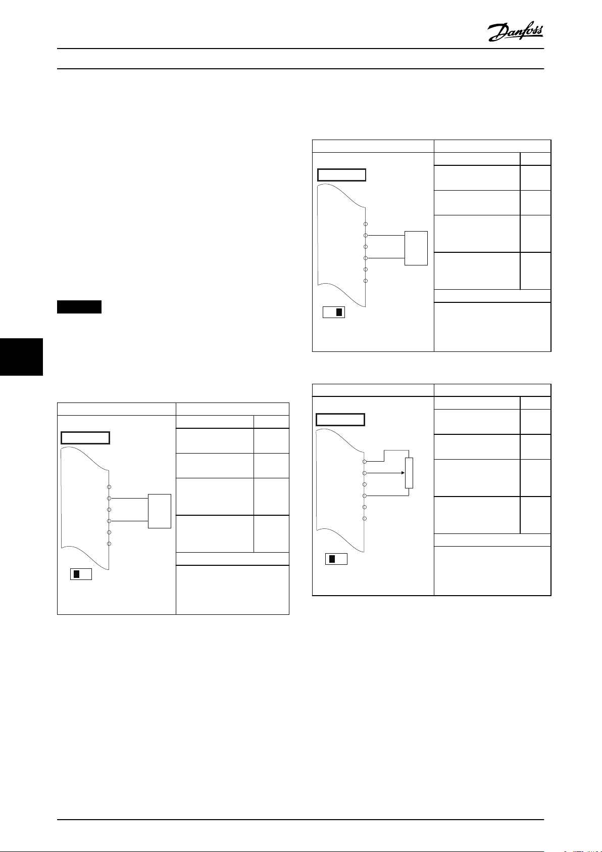
+10
V
A IN
A IN
COM
A OUT
COM
50
53
54
55
42
39
A53
U - I
0 – 10 V
+
-
e30bb926.11
FC
+10
V
A IN
A IN
COM
A OUT
COM
50
53
54
55
42
39
+
-
FC
e30bb927.11
A53
U - I
4 - 20mA
+10
V
A IN
A IN
COM
A OUT
COM
50
53
54
55
42
39
A53
U - I
≈ 5kΩ
e30bb683.11
FC
Wiring Conguration Exampl... VLT® AutomationDrive FC 361
8 Wiring Conguration Examples
8.1 Introduction
The examples in this section are intended as a quick
reference for common applications.
Parameter settings are the regional default values
•
unless otherwise indicated (selected in
parameter 0-03 Regional Settings).
Parameters associated with the terminals and
•
their settings are shown next to the drawings.
Required switch settings for analog terminals A53
•
or A54 are also shown.
NOTICE
When not using the optional STO feature, a jumper wire
is required between terminal 12 (or 13) and terminal 37
for the drive to operate with factory default
88
programming values.
8.2 Wiring for Open-loop Speed Control
Parameters
Function Setting
Parameter 6-10 Termi
nal 53 Low Voltage
Parameter 6-11 Termi
nal 53 High Voltage
Parameter 6-14 Termi
nal 53 Low Ref./
Feedb. Value
Parameter 6-15 Termi
nal 53 High Ref./
Feedb. Value
* = Default value
Notes/comments:
Assumptions are 0 V DC input
= 0 Hz speed and 10 V DC
input = 50 Hz speed.
0.07 V*
10 V*
0 Hz
50 Hz
Parameters
Function Setting
Parameter 6-12 Terminal
53 Low Current
Parameter 6-13 Terminal
53 High Current
Parameter 6-14 Terminal
53 Low Ref./Feedb.
Value
Parameter 6-15 Terminal
53 High Ref./Feedb.
Value
* = Default value
Notes/comments:
Assumptions are 4 mA input =
0 Hz speed and 20 mA input =
50 Hz speed.
Table 8.2 Analog Speed Reference (Current)
Parameters
Function Setting
Parameter 6-12 Terminal
53 Low Current
Parameter 6-13 Terminal
53 High Current
Parameter 6-14 Terminal
53 Low Ref./Feedb.
Value
Parameter 6-15 Terminal
53 High Ref./Feedb.
Value
* = Default value
Notes/comments:
Assumptions are 0 V DC input
= 0 RPM speed and 10 V DC
input = 1500 RPM speed.
Table 8.3 Speed Reference (Using a Manual Potentiometer)
4 mA*
20 mA*
0 Hz
50 Hz
4 mA*
20 mA*
0 Hz
50 Hz
Table 8.1 Analog Speed Reference (Voltage)
40 Danfoss A/S © 06/2018 All rights reserved. MG06I102
Page 43
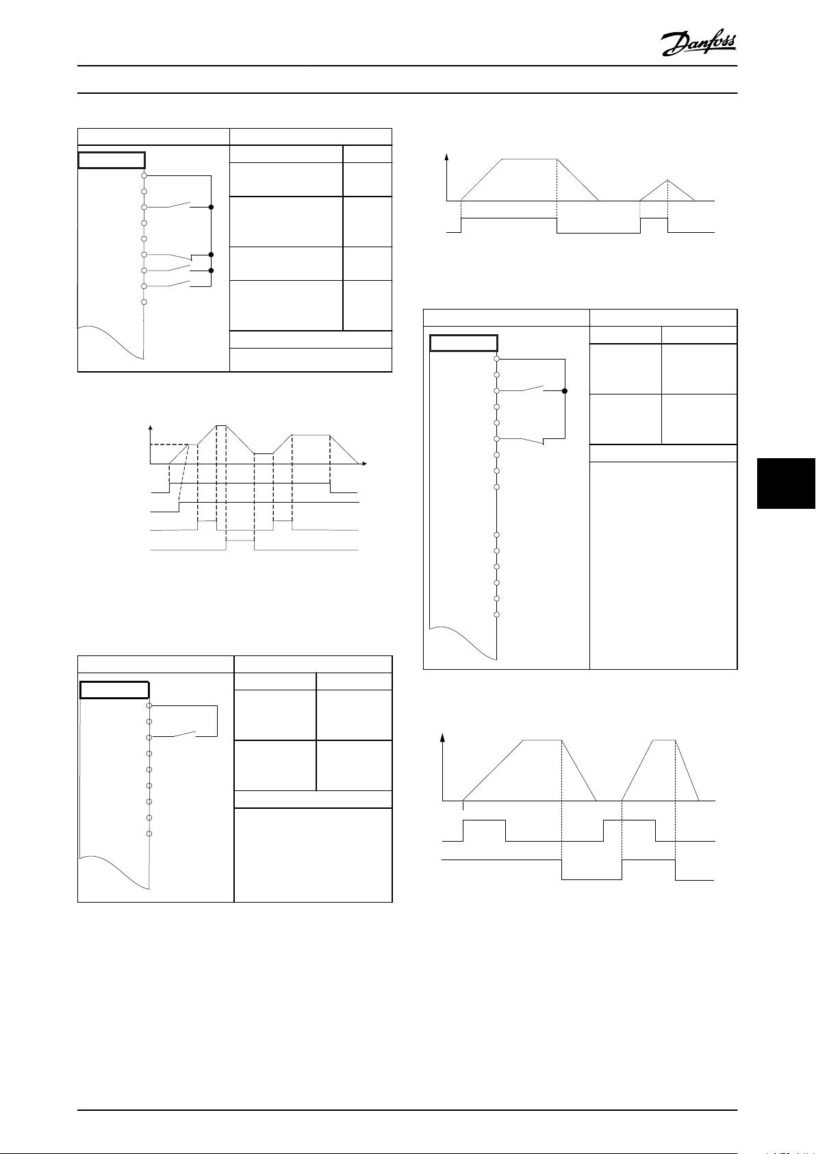
FC
+24 V
+24 V
D IN
D IN
D IN
COM
D IN
D IN
D IN
12
13
18
19
20
27
29
32
33
e30bg503.10
130BB840.12
Speed
Reference
Start (18)
Freeze ref (27)
Speed up (29)
Speed down (32)
FC
+24 V
+24 V
D IN
D IN
D IN
COM
D IN
D IN
D IN
12
13
18
19
20
27
29
32
33
e30bg504.10
130BB805.12
Speed
Start/Stop (18)
FC
+24 V
+24 V
D IN
D IN
D IN
COM
D IN
D IN
D IN
+10 V
A IN
A IN
COM
A OUT
COM
12
13
18
19
20
27
29
32
33
50
53
54
55
42
39
e30bg505.10
Speed
130BB806.10
Latched Start (18)
Stop Inverse (27)
Wiring Conguration Exampl... Operating Guide
Parameters
Function Setting
Parameter 5-10 Termin
al 18 Digital Input
Parameter 5-12 Termin
al 27 Digital Input
Parameter 5-13 Termin
al 29 Digital Input
Parameter 5-14 Termin
al 32 Digital Input
* = Default value
Notes/comments:
Table 8.4 Speed Up/Speed Down
[8] Start*
[19]
Freeze
Reference
[21]
Speed Up
[22]
Speed
Down
Illustration 8.2 Start/Stop Command
Parameters
Function Setting
Parameter 5-1
[9] Latched
0 Terminal 18
Digital Input
Parameter 5-1
2 Terminal 27
Digital Input
* = Default value
Notes/comments:
Start
[6] Stop
Inverse
8 8
Illustration 8.1 Speed Up/Speed Down
8.3 Wiring for Start/Stop
Parameters
Function Setting
Parameter 5-10
[8] Start*
Terminal 18
Digital Input
Parameter 5-12
Terminal 27
[0] No
operation
Digital Input
* = Default value
Notes/comments:
If parameter 5-12 Terminal 27
Digital Input is set to [0] No
operation, a jumper wire to
terminal 27 is not needed.
Table 8.5 Start/Stop Command
MG06I102 Danfoss A/S © 06/2018 All rights reserved. 41
Table 8.6 Pulse Start/Stop
Illustration 8.3 Latched Start/Stop Inverse
Page 44

FC
+24 V
+24 V
D IN
D IN
D IN
COM
D IN
D IN
D IN
+10 V
A IN
A IN
COM
A OUT
COM
12
13
18
19
20
27
29
32
33
50
53
54
55
42
39
130BB934.11
FC
+24 V
+24 V
D IN
D IN
D IN
COM
D IN
D IN
D IN
+10
V
A IN
A IN
COM
A OUT
COM
12
13
18
19
20
27
29
32
33
50
53
54
55
42
39
e30bg506.10
e30bg507.10
VLT
+24 V
+24 V
D IN
D IN
D IN
COM
D IN
D IN
D IN
+10 V
A IN
A IN
COM
A OUT
COM
12
13
18
19
20
27
29
32
33
50
53
54
55
42
39
A53
U - I
Wiring Conguration Exampl... VLT® AutomationDrive FC 361
Parameters
Wiring for a Motor Thermistor
8.5
Function Setting
Parameter 5-10
Terminal 18
Digital Input
Parameter 5-11
Terminal 19
Digital Input
Parameter 5-12
Terminal 27
Digital Input
Parameter 5-14
Terminal 32
Digital Input
Parameter 5-15
Terminal 33
Digital Input
Parameter 3-10
Preset
Reference
Preset ref. 0
88
Preset ref. 1
Preset ref. 2
Preset ref. 3
* = Default value
Notes/comments:
[8] Start
[10]
Reversing*
[0] No
operation
[16] Preset
ref bit 0
[17] Preset
ref bit 1
25%
50%
75%
100%
WARNING
THERMISTOR INSULATION
Risk of personal injury or equipment damage.
To meet PELV insulation requirements, use only
•
thermistors with reinforced or double
insulation.
Parameters
Function Setting
Parameter 1-90
Motor Thermal
Protection
Parameter 1-93
Thermistor
Resource
* = Default value
Notes/comments:
If only a warning is desired, set
parameter 1-90 Motor Thermal
Protection to [1] Thermistor
warning.
[2] Thermistor
trip
[1] Analog
input 53
Table 8.7 Start/Stop with Reversing and 4 Preset Speeds
Wiring for External Alarm Reset
8.4
Parameters
Function Setting
Parameter 5-11 T
erminal 19
[1] Reset
Table 8.9 Motor Thermistor
Digital Input
* = Default value
Notes/comments:
Table 8.8 External Alarm Reset
42 Danfoss A/S © 06/2018 All rights reserved. MG06I102
Page 45

130BD430.10
Maintenance, Diagnostics, a... Operating Guide
9 Maintenance, Diagnostics, and Troubleshooting
This chapter includes:
Maintenance and service guidelines.
•
Status messages.
•
Warnings and alarms.
•
Basic troubleshooting.
•
9.1 Maintenance and Service
Under normal operating conditions and load
drive is maintenance-free throughout its designed lifetime.
To prevent breakdown, danger, and damage, examine the
drive at regular intervals depending on the operating
conditions. Replace worn or damaged parts with original
spare parts or standard parts. For service and support, refer
to www.danfoss.com/en/contact-us/contacts-list/?lter=type
%3Adanfoss-sales-service-center%2Csegments%3ADDS.
proles, the
WARNING
UNINTENDED START
When the drive is connected to AC mains, DC supply, or
load sharing, the motor can start at any time.
Unintended start during programming, service, or repair
work can result in death, serious injury, or property
damage. The motor can start with an external switch, a
eldbus command, an input reference signal from the
LCP or LOP, via remote operation using MCT 10 Set-up
Software, or after a cleared fault condition.
To prevent unintended motor start:
Press [O/Reset] on the LCP before
•
programming parameters.
Disconnect the drive from the mains.
•
Completely wire and assemble the drive, motor,
•
and any driven equipment before connecting
the drive to AC mains, DC supply, or load
sharing.
9.2 Heat Sink Access Panel
9.2.1 Removing the Heat Sink Access Panel
The drive can be ordered with an optional access panel in
the back of the unit. This panel provides access to the heat
sink and allows the heat sink to be cleaned of any dust
buildup.
Illustration 9.1 Heat Sink Access Panel
NOTICE
DAMAGE TO HEAT SINK
Using fasteners that are longer than those originally
supplied with the heat sink panel can damage the heat
sink cooling ns.
1. Remove power from the drive and wait 20
minutes for the capacitors to discharge
completely. Refer to chapter 2 Safety.
2. Position the drive so that the back of the drive is
accessible.
3. Remove the screws (3 mm [0.12 in] internal hex)
connecting the access panel to the back of the
enclosure. There are 5 or 9 screws depending on
the size of the drive.
4. Inspect the heat sink for damage or dust buildup.
5. Remove dust and debris with a vacuum.
6. Replace the panel and secure it to the back of
the enclosure with the screws previously
removed. Tighten the fasteners according to
chapter 10.8 Fastener Tightening Torques.
9 9
MG06I102 Danfoss A/S © 06/2018 All rights reserved. 43
Page 46

Status
799RPM 7.83A 36.4kW
0.000
53.2%
1(1)
Auto
Hand
O
Remote
Local
Ramping
Stop
Running
Jogging
.
.
.
Stand-by
130BB037.11
1
2
3
Maintenance, Diagnostics, a... VLT® AutomationDrive FC 361
9.3 Status Messages
When the drive is in status mode, status messages
automatically appear in the lowest line of the LCP display.
Refer to Illustration 9.2. Status messages are dened in
Table 9.1 – Table 9.3.
1 Where the stop/start command originates. Refer to Table 9.1.
2 Where the speed control originates. Refer to Table 9.2.
3 Provides the drive status. Refer to Table 9.3.
99
Illustration 9.2 Status Display
NOTICE
In auto/remote mode, the drive requires external
commands to execute functions.
Table 9.1 to Table 9.3 dene the meaning of the shown
status messages.
O The drive does not react to any control signal
until [Auto On] or [Hand On] is pressed.
Auto The start/stop commands are sent via the
control terminals and/or the serial communi-
cation.
Hand The navigation keys on the LCP can be used
to control the drive. Stop commands, reset,
reversing, DC brake, and other signals applied
to the control terminals override local control.
Table 9.1 Operating Mode
Remote The speed reference is given from
External signals.
•
Local The drive uses reference values from the LCP.
Serial communication.
•
Internal preset references.
•
AC brake AC brake was selected in parameter 2-10 Brake
Function. The AC brake overmagnetizes the
motor to achieve a controlled slow down.
AMA nish OK Automatic motor adaptation (AMA) was
carried out successfully.
AMA ready AMA is ready to start. To start, press [Hand
On].
AMA running AMA process is in progress.
Coast
Ctrl. ramp-down [1] Ctrl. ramp-down was selected in
Current high The drive output current is above the limit set
Current low The drive output current is below the limit set
DC hold DC hold is selected in parameter 1-80 Function
DC stop The motor is held with a DC current
Feedback high The sum of all active feedbacks is above the
Feedback low The sum of all active feedbacks is below the
[2] Coast inverse was selected as a function
•
for a digital input (parameter group 5-1*
Digital Inputs). The corresponding terminal
is not connected.
Coast activated by serial communication.
•
parameter 14-10 Mains Failure.
The mains voltage is below the value set
•
in parameter 14-11 Mains Voltage at Mains
Fault at mains fault.
The drive ramps down the motor using a
•
controlled ramp down.
in parameter 4-51 Warning Current High.
in parameter 4-52 Warning Speed Low.
at Stop and a stop command is active. The
motor is held by a DC current set in
parameter 2-00 DC Hold Current.
(parameter 2-01 DC Brake Current) for a
specied time (parameter 2-02 DC Braking
Time).
DC brake is activated in parameter 2-03 DC
•
Brake Cut In Speed [RPM] and a stop
command is active.
DC brake (inverse) is selected as a function
•
for a digital input (parameter group 5-1*
Digital Inputs). The corresponding terminal
is not active.
The DC brake is activated via serial
•
communication.
feedback limit set in parameter 4-57 Warning
Feedback High.
feedback limit set in parameter 4-56 Warning
Feedback Low.
Table 9.2 Reference Site
44 Danfoss A/S © 06/2018 All rights reserved. MG06I102
Page 47

Maintenance, Diagnostics, a... Operating Guide
Freeze output The remote reference is active, which holds
the present speed.
[20] Freeze Output was selected as a
•
function for a digital input (parameter
group 5-1* Digital Inputs). The
corresponding terminal is active. Speed
control is only possible via the terminal
functions speed up and speed down.
Hold ramp is activated via serial communi-
•
cation.
Freeze output
request
Freeze ref. [19] Freeze Reference was selected as a
Jog request A jog command has been given, but the
Jogging The motor is running as programmed in
OVC control Overvoltage control was activated in
Power unit o (For drives with a 24 V DC external supply
A freeze output command has been given, but
the motor remains stopped until a run
permissive signal is received.
function for a digital input (parameter group
5-1* Digital Inputs). The corresponding terminal
is active. The drive saves the actual reference.
Changing the reference is now only possible
via terminal functions speed up and speed
down.
motor is stopped until a run permissive signal
is received via a digital input.
parameter 3-19 Jog Speed [RPM].
[14] Jog was selected as function for a
•
digital input (parameter group 5-1* Digital
Inputs). The corresponding terminal (for
example, terminal 29) is active.
The jog function is activated via the serial
•
communication.
The jog function was selected as a reaction
•
for a monitoring function (for example, No
signal). The monitoring function is active.
parameter 2-17 Over-voltage Control, [2]
Enabled. The connected motor is supplying
the drive with generative energy. The
overvoltage control adjusts the V/Hz ratio to
run the motor in controlled mode and to
prevent the drive from tripping.
installed only.) Mains supply to the drive is
removed, but the control card is supplied by
the 24 V DC external supply.
Protection md Protection mode is active. The unit has
detected a critical status (an overcurrent or
overvoltage).
To avoid tripping, the switching frequency
•
is reduced to 1500 kHz if
parameter 14-55 Output Filter is set to [2]
Sine-Wave Filter Fixed. Otherwise, the
switching frequency is reduced to 1000 Hz.
If possible, protection mode ends after
•
approximately 10 s.
Protection mode can be restricted in
•
parameter 14-26 Trip Delay at Inverter Fault.
QStop The motor is decelerating using
parameter 3-81 Quick Stop Ramp Time.
[4] Quick stop inverse was selected as a
•
function for a digital input (parameter
group 5-1* Digital Inputs). The
corresponding terminal is not active.
The quick stop function was activated via
•
serial communication.
Ramping The motor is accelerating/decelerating using
the active ramp up/down. The reference, a
limit value, or a standstill is not yet reached.
Ref. high The sum of all active references is above the
reference limit set in parameter 4-55 Warning
Reference High.
Ref. low The sum of all active references is below the
reference limit set in parameter 4-54 Warning
Reference Low.
Run on ref. The drive is running in the reference range.
The feedback value matches the setpoint
value.
Run request A start command has been given, but the
motor is stopped until a run permissive signal
is received via digital input.
Running The drive is driving the motor.
Sleep mode The energy saving function is enabled. This
function being enabled means that now the
motor has stopped, but that it restarts
automatically when required.
Speed high The motor speed is above the value set in
parameter 4-53 Warning Speed High.
Speed low The motor speed is below the value set in
parameter 4-52 Warning Speed Low.
Standby In auto-on mode, the drive starts the motor
with a start signal from a digital input or serial
communication.
Start delay In parameter 1-71 Start Delay, a delay starting
time was set. A start command is activated
and the motor starts after the start delay time
expires.
9 9
MG06I102 Danfoss A/S © 06/2018 All rights reserved. 45
Page 48
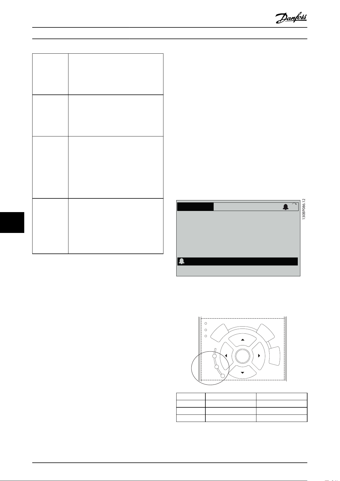
130BP086.12
Status
0.0Hz 0.000kW 0.00A
0.0Hz
0
Earth Fault [A14]
Auto Remote Trip
1(1)
Back
Cancel
Info
OK
On
Alarm
Warn.
130BB467.11
Maintenance, Diagnostics, a... VLT® AutomationDrive FC 361
Start fwd/rev [12] Enable Start Forward and [13] Enable Start
Reverse were selected as functions for 2
dierent digital inputs (parameter group 5-1*
Digital Inputs). The motor starts in forward or
reverse depending on which corresponding
terminal is activated.
Stop The drive has received a stop command from
1 of the following:
LCP.
•
Digital input.
•
Serial communication.
•
Trip An alarm occurred and the motor is stopped.
Once the cause of the alarm is cleared, reset
the drive using 1 of the following:
Pressing [Reset].
•
Remotely by control terminals.
•
Via serial communication.
•
Pressing [Reset] or remotely by control
terminals or via serial communication.
Trip lock An alarm occurred and the motor is stopped.
Once the cause of the alarm is cleared, cycle
power to the drive. Reset the drive manually
99
by 1 of the following:
Pressing [Reset].
•
Remotely by control terminals.
•
Via serial communication.
•
Trip
When tripping, the drive suspends operation to prevent
damage to the drive and other equipment. When a trip
occurs, the motor coasts to a stop. The drive logic
continues to operate and monitor the drive status. After
the fault condition is remedied, the drive is ready for a
reset.
Trip lock
When trip locking, the drive suspends operation to prevent
damage to the drive and other equipment. When a trip
lock occurs, the motor coasts to a stop. The drive logic
continues to operate and monitor the drive status. The
drive starts a trip lock only when serious faults occur that
can damage the drive or other equipment. After the faults
are xed, cycle the input power before resetting the drive.
Warning and alarm displays
A warning is shown in the LCP along with the
•
warning number.
An alarm ashes along with the alarm number.
•
Table 9.3 Operation Status
Warning and Alarm Types
9.4
The drive software issues warnings and alarms to help in
diagnosing issues. The warning or alarm number appears
in the LCP.
Warning
A warning indicates that the drive has encountered an
abnormal operating condition that leads to an alarm. A
warning stops when the abnormal condition is removed or
resolved.
Alarm
An alarm indicates a fault that requires immediate
attention. The fault always triggers a trip or trip lock. Reset
the drive after an alarm.
Reset the drive in any of 4 ways:
Press [Reset]/[O/Reset].
•
Digital reset input command.
•
Serial communication reset input command.
•
•
Auto reset.
Illustration 9.3 Alarm Example
In addition to the text and alarm code in the LCP, there are
3 status indicator lights.
Warning indicator light Alarm indicator light
Warning On O
Alarm O On (ashing)
Trip lock On On (ashing)
Illustration 9.4 Status Indicator Lights
46 Danfoss A/S © 06/2018 All rights reserved. MG06I102
Page 49

Maintenance, Diagnostics, a... Operating Guide
9.5 List of Warnings and Alarms
The following warning and alarm information denes each
warning or alarm condition, provides the probable cause
for the condition, and details a remedy or troubleshooting
procedure.
WARNING 1, 10 Volts low
The control card voltage is less than 10 V from terminal 50.
Remove some of the load from terminal 50, as the 10 V
supply is overloaded. Maximum 15 mA or minimum 590 Ω.
A short circuit in a connected potentiometer or incorrect
wiring of the potentiometer can cause this condition.
Troubleshooting
Remove the wiring from terminal 50. If the
•
warning clears, the problem is with the wiring. If
the warning does not clear, replace the control
card.
WARNING/ALARM 2, Live zero error
This warning or alarm only appears if programmed in
parameter 6-01 Live Zero Timeout Function. The signal on 1
of the analog inputs is less than 50% of the minimum
value programmed for that input. Broken wiring or a faulty
device sending the signal can cause this condition.
Troubleshooting
Check connections on all analog mains terminals.
•
- Control card terminals 53 and 54 for
signals, terminal 55 common.
-
VLT® General Purpose I/O MCB 101
terminals 11 and 12 for signals, terminal
10 common.
Check that the drive programming and switch
•
settings match the analog signal type.
Perform an input terminal signal test.
•
WARNING/ALARM 3, No motor
No motor has been connected to the output of the drive.
WARNING/ALARM 4, Mains phase loss
A phase is missing on the supply side, or the mains
voltage imbalance is too high. This message also appears
for a fault in the input rectier. Options are programmed in
parameter 14-12 Function at Mains Imbalance.
Troubleshooting
Check the supply voltage and supply currents to
•
the drive.
WARNING 5, DC link voltage high
The DC-link voltage (DC) is higher than the high-voltage
warning limit. The limit depends on the drive voltage
rating. The unit is still active.
WARNING 6, DC link voltage low
The DC-link voltage (DC) is lower than the low-voltage
warning limit. The limit depends on the drive voltage
rating. The unit is still active.
WARNING/ALARM 7, DC overvoltage
If the DC-link voltage exceeds the limit, the drive trips after
a certain time.
Troubleshooting
Connect a brake resistor.
•
Extend the ramp time.
•
Change the ramp type.
•
Activate the functions in parameter 2-10 Brake
•
Function.
Increase parameter 14-26 Trip Delay at Inverter
•
Fault.
If the alarm/warning occurs during a power sag,
•
use kinetic back-up (parameter 14-10 Mains
Failure).
WARNING/ALARM 8, DC under voltage
If the DC-link voltage drops below the undervoltage limit,
the drive checks for 24 V DC back-up supply. If no 24 V DC
back-up supply is connected, the drive trips after a xed
time delay. The time delay varies with unit size.
Troubleshooting
Check that the supply voltage matches the drive
•
voltage.
Perform an input voltage test.
•
Perform a soft-charge circuit test.
•
WARNING/ALARM 9, Inverter overload
The drive has run with more than 100% overload for too
long and is about to cut out. The counter for electronic
thermal inverter protection issues a warning at 98% and
trips at 100% with an alarm. The drive cannot be reset
until the counter is below 90%.
Troubleshooting
Compare the output current shown on the LCP
•
with the drive rated current.
Compare the output current shown on the LCP
•
with the measured motor current.
Show the thermal drive load on the LCP and
•
monitor the value. When running above the drive
continuous current rating, the counter increases.
When running below the drive continuous
current rating, the counter decreases.
WARNING/ALARM 10, Motor overload temperature
According to the electronic thermal protection (ETR), the
motor is too hot.
Select 1 of these options:
The drive issues a warning or an alarm when the
•
counter is >90% if parameter 1-90 Motor Thermal
Protection is set to warning options.
The drive trips when the counter reaches 100% if
•
parameter 1-90 Motor Thermal Protection is set to
trip options.
9 9
MG06I102 Danfoss A/S © 06/2018 All rights reserved. 47
Page 50

Maintenance, Diagnostics, a... VLT® AutomationDrive FC 361
The fault occurs when the motor runs with more than
100% overload for too long.
Troubleshooting
Check for motor overheating.
•
Check if the motor is mechanically overloaded.
•
Check that the motor current set in
•
parameter 1-24 Motor Current is correct.
Ensure that the motor data in parameters 1-20 to
•
1-25 is set correctly.
If an external fan is in use, check that it is
•
selected in parameter 1-91 Motor External Fan.
Running AMA in parameter 1-29 Automatic Motor
•
Adaptation (AMA) tunes the drive to the motor
more accurately and reduces thermal loading.
WARNING/ALARM 11, Motor thermistor overtemp
Check whether the thermistor is disconnected. Select
whether the drive issues a warning or an alarm in
parameter 1-90 Motor Thermal Protection.
Troubleshooting
Check for motor overheating.
•
Check if the motor is mechanically overloaded.
•
99
WARNING/ALARM 12, Torque limit
The torque has exceeded the value in
parameter 4-16 Torque Limit Motor Mode or the value in
parameter 4-17 Torque Limit Generator Mode.
Parameter 14-25 Trip Delay at Torque Limit can change this
warning from a warning-only condition to a warning
followed by an alarm.
Troubleshooting
When using terminal 53 or 54, check that the
•
thermistor is connected correctly between either
terminal 53 or 54 (analog voltage input) and
terminal 50 (+10 V supply). Also check that the
terminal switch for 53 or 54 is set for voltage.
Check that parameter 1-93 Thermistor Resource
selects terminal 53 or 54.
When using terminal 18, 19, 31, 32, or 33 (digital
•
inputs), check that the thermistor is connected
correctly between the digital input terminal used
(digital input PNP only) and terminal 50. Select
the terminal to use in parameter 1-93 Thermistor
Resource.
If the motor torque limit is exceeded during
•
ramp-up, extend the ramp-up time.
If the generator torque limit is exceeded during
•
ramp-down, extend the ramp-down time.
If torque limit occurs while running, increase the
•
torque limit. Make sure that the system can
operate safely at a higher torque.
Check the application for excessive current draw
•
on the motor.
WARNING/ALARM 13, Over current
The inverter peak current limit (approximately 200% of the
rated current) is exceeded. The warning lasts approximately
1.5 s, then the drive trips and issues an alarm. Shock
loading or quick acceleration with high-inertia loads can
cause this fault. If the acceleration during ramp-up is quick,
the fault can also appear after kinetic back-up.
If extended mechanical brake control is selected, a trip can
be reset externally.
Troubleshooting
Remove the power and check if the motor shaft
•
can be turned.
Check that the motor size matches the drive.
•
Check that the motor data is correct in
•
parameters 1-20 to 1-25.
ALARM 14, Earth (ground) fault
There is current from the output phase to ground, either in
the cable between the drive and the motor, or in the
motor itself. The current transducers detect the ground
fault by measuring current going out from the drive and
current going into the drive from the motor. Ground fault
is issued if the deviation of the 2 currents is too large. The
current going out of the drive must be the same as the
current going into the drive.
Troubleshooting
Remove power to the drive and repair the ground
•
fault.
Check for ground faults in the motor by
•
measuring the resistance to ground of the motor
cables and the motor with a megohmmeter.
Reset any potential individual oset in the 3
•
current transducers in the drive. Perform the
manual initialization or perform a complete AMA.
This method is most relevant after changing the
power card.
ALARM 15, Hardware mismatch
A tted option is not operational with the present control
card hardware or software.
Record the value of the following parameters and contact
Danfoss.
Parameter 15-40 FC Type.
•
Parameter 15-41 Power Section.
•
Parameter 15-42 Voltage.
•
Parameter 15-43 Software Version.
•
Parameter 15-45 Actual Typecode String.
•
Parameter 15-49 SW ID Control Card.
•
Parameter 15-50 SW ID Power Card.
•
Parameter 15-60 Option Mounted.
•
Parameter 15-61 Option SW Version (for each
•
option slot).
48 Danfoss A/S © 06/2018 All rights reserved. MG06I102
Page 51

Maintenance, Diagnostics, a... Operating Guide
ALARM 16, Short circuit
There is short-circuiting in the motor or motor wiring.
Troubleshooting
Remove the power to the drive and repair the
•
short circuit.
WARNING
HIGH VOLTAGE
Drives contain high voltage when connected to AC mains
input, DC supply, or load sharing. Failure to use qualied
personnel to install, start up, and maintain the drive can
result in death or serious injury.
Disconnect power before proceeding.
•
WARNING/ALARM 17, Control word timeout
There is no communication to the drive.
The warning is only active when parameter 8-04 Control
Word Timeout Function is NOT set to [0] O.
If parameter 8-04 Control Word Timeout Function is set to [5]
Stop and trip, a warning appears, and the drive ramps
down to a stop and shows an alarm.
Troubleshooting
Check the connections on the serial communi-
•
cation cable.
Increase parameter 8-03 Control Word Timeout
•
Time.
Check the operation of the communication
•
equipment.
Verify that proper EMC installation was
•
performed.
ALARM 18, Start failed
The speed cannot exceed the value set in
parameter 1-78 Compressor Start Max Speed [Hz] during
start within the allowed time which is set in
parameter 1-79 Compressor Start Max Time to Trip. The
alarm may be caused by a blocked motor.
WARNING/ALARM 21, Parameter error
The parameter is out of range. The parameter number is
shown in the display.
Troubleshooting
Set the
•
WARNING 23, Internal fan fault
The fan warning function is a protective function that
checks if the fan is running/mounted. The fan warning can
be disabled in parameter 14-53 Fan Monitor ([0] Disabled).
For drives with DC fans, a feedback sensor is mounted in
the fan. If the fan is commanded to run and there is no
feedback from the sensor, this alarm appears. For drives
with AC fans, the voltage to the fan is monitored.
aected parameter to a valid value.
Troubleshooting
Check for proper fan operation.
•
Cycle power to the drive and check that the fan
•
operates briey at start-up.
Check the sensors on the control card.
•
WARNING 24, External fan fault
The fan warning function is a protective function that
checks if the fan is running/mounted. The fan warning can
be disabled in parameter 14-53 Fan Monitor ([0] Disabled).
For drives with DC fans, a feedback sensor is mounted in
the fan. If the fan is commanded to run and there is no
feedback from the sensor, this alarm appears. For drives
with AC fans, the voltage to the fan is monitored.
Troubleshooting
Check for proper fan operation.
•
Cycle power to the drive and check that the fan
•
operates briey at start-up.
Check the sensors on the heat sink.
•
ALARM 29, Power module temp
The power module is over temperature. If the enclosure is
IP00 or IP20/NEMA 1, the cutout temperature of the heatsink is 90 °C (194 °F). If the enclosure is IP54, the cutout
temperature is 80 °C (176 °F).
ALARM 30, Motor phase U missing
Motor phase U between the drive and the motor is
missing.
WARNING
HIGH VOLTAGE
Drives contain high voltage when connected to AC mains
input, DC supply, or load sharing. Failure to perform
installation, start-up, and maintenance by qualied
personnel can result in death or serious injury.
Only qualied personnel must perform instal-
•
lation, start-up, and maintenance.
Before performing any service or repair work,
•
use an appropriate voltage measuring device to
make sure that there is no remaining voltage on
the drive.
Troubleshooting
Remove the power from the drive and check
•
motor phase U.
ALARM 31, Motor phase V missing
Motor phase V between the drive and the motor is
missing.
9 9
MG06I102 Danfoss A/S © 06/2018 All rights reserved. 49
Page 52
Maintenance, Diagnostics, a... VLT® AutomationDrive FC 361
WARNING
HIGH VOLTAGE
Drives contain high voltage when connected to AC mains
input, DC supply, or load sharing. Failure to perform
installation, start-up, and maintenance by qualied
personnel can result in death or serious injury.
Only qualied personnel must perform instal-
•
lation, start-up, and maintenance.
Before performing any service or repair work,
•
use an appropriate voltage measuring device to
make sure that there is no remaining voltage on
the drive.
Troubleshooting
Remove the power from the drive and check
•
motor phase V.
ALARM 32, Motor phase W missing
Motor phase W between the drive and the motor is
missing.
WARNING
99
HIGH VOLTAGE
Drives contain high voltage when connected to AC mains
input, DC supply, or load sharing. Failure to perform
installation, start-up, and maintenance by qualied
personnel can result in death or serious injury.
Only qualied personnel must perform instal-
•
lation, start-up, and maintenance.
Before performing any service or repair work,
•
use an appropriate voltage measuring device to
make sure that there is no remaining voltage on
the drive.
Troubleshooting
Remove the power from the drive and check
•
motor phase W.
ALARM 33, Inrush fault
Too many power-ups have occurred within a short time
period.
Troubleshooting
Let the unit cool to operating temperature.
•
Check potential DC-link fault to ground.
•
WARNING/ALARM 34, Fieldbus communication fault
The eldbus on the communication option card is not
working.
WARNING/ALARM 35, Option fault
An option alarm is received. The alarm is option-specic.
The most likely cause is a power-up or a communication
fault.
WARNING/ALARM 36, Mains failure
This warning/alarm is only active if the supply voltage to
the drive is lost and parameter 14-10 Mains Failure is not
set to [0] No function.
Troubleshooting
Check the fuses to the drive and mains supply to
•
the unit.
ALARM 37, Phase imbalance
There is a current imbalance between the power units.
ALARM 38, Internal fault
When an internal fault occurs, a code number dened in
Table 9.4 is shown.
Troubleshooting
Cycle power.
•
Check that the option is properly installed.
•
Check for loose or missing wiring.
•
It may be necessary to contact the Danfoss supplier or
service department. Note the code number for further
troubleshooting directions.
Number Text
0 The serial port cannot be initialized. Contact the
Danfoss supplier or Danfoss service department.
256–258 The power EEPROM data is defective or too old.
Replace the power card.
512–519 Internal fault. Contact the Danfoss supplier or
Danfoss service department.
783 Parameter value outside of minimum/maximum
limits.
1024–1284 Internal fault. Contact the Danfoss supplier or
Danfoss service department.
1299 The option software in slot A is too old.
1300 The option software in slot B is too old.
1302 The option software in slot C1 is too old.
1315 The option software in slot A is not supported/
allowed.
1316 The option software in slot B is not supported/
allowed.
1318 The option software in slot C1 is not supported/
allowed.
1379–2819 Internal fault. Contact the Danfoss supplier or
Danfoss service department.
1792 Hardware reset of digital signal processor.
1793 Motor-derived parameters not transferred correctly
to the digital signal processor.
1794 Power data not transferred correctly at power-up
to the digital signal processor.
1795 The digital signal processor has received too many
unknown SPI telegrams. The AC drive also uses
this fault code if the MCO does not power up
correctly. This situation can occur due to poor EMC
protection or improper grounding.
1796 RAM copy error.
50 Danfoss A/S © 06/2018 All rights reserved. MG06I102
Page 53

Maintenance, Diagnostics, a... Operating Guide
Number Text
2561 Replace the control card.
2820 LCP stack overow.
2821 Serial port overow.
2822 USB port overow.
3072–5122 Parameter value is outside its limits.
5123 Option in slot A: Hardware incompatible with the
control board hardware.
5124 Option in slot B: Hardware incompatible with the
control board hardware.
5125 Option in slot C0: Hardware incompatible with the
control board hardware.
5126 Option in slot C1: Hardware incompatible with the
control board hardware.
5376–6231 Internal fault. Contact the Danfoss supplier or
Danfoss service department.
Table 9.4 Internal Fault Codes
ALARM 39, Heat sink sensor
No feedback from the heat sink temperature sensor.
The signal from the IGBT thermal sensor is not available on
the power card. The problem could be on the power card,
on the gatedrive card, or the ribbon cable between the
power card and gatedrive card.
WARNING 40, Overload of digital output terminal 27
Check the load connected to terminal 27 or remove the
short-circuit connection. Check parameter 5-00 Digital I/O
Mode and parameter 5-01 Terminal 27 Mode.
WARNING 41, Overload of digital output terminal 29
Check the load connected to terminal 29 or remove the
short-circuit connection. Also check parameter 5-00 Digital
I/O Mode and parameter 5-02 Terminal 29 Mode.
WARNING 42, Overload of digital output on X30/6 or
overload of digital output on X30/7
For terminal X30/6, check the load connected to terminal
X30/6 or remove the short-circuit connection. Also check
parameter 5-32 Term X30/6 Digi Out (MCB 101) (VLT
General Purpose I/O MCB 101).
For terminal X30/7, check the load connected to terminal
X30/7 or remove the short-circuit connection. Check
parameter 5-33 Term X30/7 Digi Out (MCB 101) (VLT
General Purpose I/O MCB 101).
ALARM 45, Earth fault 2
Ground fault.
Troubleshooting
Check for proper grounding and loose
•
connections.
Check for proper wire size.
•
Check the motor cables for short circuits or
•
leakage currents.
®
®
ALARM 46, Power card supply
The supply for the gate drive on the power card is out of
range.
Troubleshooting
Check for a defective power card.
•
WARNING 47, 24 V supply low
The 24 V DC is measured on the control card.
Troubleshooting
Contact the Danfoss supplier or Danfoss Service
•
Department.
WARNING 48, 1.8 V supply low
The 1.2 V DC supply used on the control card is outside of
the allowable limits. The supply is measured on the control
card.
Troubleshooting
Check for a defective control card.
•
If an option card is present, check for
•
overvoltage.
WARNING 49, Speed limit
The warning is shown when the speed is outside of the
specied range in parameter 4-11 Motor Speed Low Limit
[RPM] and parameter 4-13 Motor Speed High Limit [RPM].
When the speed is below the specied limit in
parameter 1-86 Trip Speed Low [RPM] (except when starting
or stopping), the drive trips.
ALARM 50, AMA calibration failed
Contact the Danfoss supplier or Danfoss Service
Department.
ALARM 51, AMA check U
The settings for motor voltage, motor current, and motor
power are wrong.
Troubleshooting
Check the settings in parameters 1-20 to 1-25.
•
ALARM 52, AMA low I
The motor current is too low.
Troubleshooting
Check the settings in parameter 1-24 Motor
•
Current.
ALARM 53, AMA motor too big
The motor is too large for the AMA to operate.
ALARM 54, AMA motor too small
The motor is too small for the AMA to operate.
ALARM 55, AMA parameter out of range
The AMA cannot run because the parameter values of the
motor are outside of the acceptable range.
ALARM 56, AMA interrupted by user
The AMA is manually interrupted.
ALARM 57, AMA internal fault
Try to restart the AMA. Repeated restarts can overheat the
motor.
nom
nom
and I
nom
9 9
MG06I102 Danfoss A/S © 06/2018 All rights reserved. 51
Page 54

Maintenance, Diagnostics, a... VLT® AutomationDrive FC 361
ALARM 58, AMA Internal fault
Contact the Danfoss supplier.
WARNING 59, Current limit
The current is higher than the value in
parameter 4-18 Current Limit. Ensure that the motor data in
parameters 1-20 to 1-25 is set correctly. Increase the current
limit if necessary. Ensure that the system can operate safely
at a higher limit.
WARNING 60, External interlock
A digital input signal indicates a fault condition external to
the drive. An external interlock has commanded the drive
to trip. Clear the external fault condition. To resume
normal operation, apply 24 V DC to the terminal
programmed for external interlock, and reset the drive.
WARNING/ALARM 61, Feedback error
An error between calculated speed and speed
measurement from feedback device.
Troubleshooting
Check the settings for warning/alarm/disabling in
•
parameter 4-30 Motor Feedback Loss Function.
Set the tolerable error in parameter 4-31 Motor
•
Feedback Speed Error.
Set the tolerable feedback loss time in
99
•
parameter 4-32 Motor Feedback Loss Timeout.
WARNING 62, Output frequency at maximum limit
If the output frequency reaches the value set in
parameter 4-19 Max Output Frequency, the drive issues a
warning. The warning ceases when the output drops
below the maximum limit. If the drive is unable to limit
the frequency, it trips and issues an alarm. The latter may
happen in the ux mode if the drive loses control of the
motor.
Troubleshooting
Check the application for possible causes.
•
Increase the output frequency limit. Ensure that
•
the system can operate safely at a higher output
frequency.
ALARM 63, Mechanical brake low
The actual motor current has not exceeded the release
brake current within the start delay time window.
WARNING 64, Voltage Limit
The load and speed combination demands a motor
voltage higher than the actual DC-link voltage.
WARNING/ALARM 65, Control card over temperature
The cutout temperature of the control card is 85 °C
(185 °F).
Troubleshooting
Check that the ambient operating temperature is
•
within the limits.
Check for clogged lters.
•
Check the fan operation.
•
Check the control card.
•
WARNING 66, Heat sink temperature low
The drive is too cold to operate. This warning is based on
the temperature sensor in the IGBT module. Increase the
ambient temperature of the unit. Also, a trickle amount of
current can be supplied to the drive whenever the motor
is stopped by setting parameter 2-00 DC Hold/Preheat
Current to 5% and parameter 1-80 Function at Stop.
ALARM 67, Option module conguration has changed
One or more options have either been added or removed
since the last power-down. Check that the conguration
change is intentional and reset the unit.
ALARM 69, Power card temperature
The temperature sensor on the power card is either too
hot or too cold.
Troubleshooting
Check that the ambient operating temperature is
•
within limits.
Check for clogged lters.
•
Check fan operation.
•
Check the power card.
•
ALARM 70, Illegal FC conguration
The control card and power card are incompatible. To
check compatibility, contact the Danfoss supplier with the
type code from the unit nameplate and the part numbers
of the cards.
WARNING 76, Power unit setup
The required number of power units does not match the
detected number of active power units. When replacing an
enclosure size F module, this warning occurs if the power-
specic data in the module power card does not match
the rest of the drive. If the power card connection is lost,
the unit also triggers this warning.
Troubleshooting
Conrm that the spare part and its power card
•
are the correct part number.
Ensure that the 44-pin cables between the MDCIC
•
and power cards are mounted properly.
WARNING 77, Reduced power mode
This warning indicates that the drive is operating in
reduced power mode (that is, less than the allowed
number of inverter sections). This warning is generated on
power cycle when the drive is set to run with fewer
inverters and remains on.
ALARM 78, Tracking error
The dierence between setpoint value and actual value
exceeds the value in parameter 4-35 Tracking Error.
Troubleshooting
Disable the function or select an alarm/warning
•
in parameter 4-34 Tracking Error Function.
Investigate the mechanics around the load and
•
motor. Check feedback connections from motor
encoder to drive.
52 Danfoss A/S © 06/2018 All rights reserved. MG06I102
Page 55

Maintenance, Diagnostics, a... Operating Guide
Select motor feedback function in
•
parameter 4-30 Motor Feedback Loss Function.
Adjust the tracking error band in
•
parameter 4-35 Tracking Error and
parameter 4-37 Tracking Error Ramping.
ALARM 79, Illegal power section conguration
The scaling card has an incorrect part number or is not
installed. The MK102 connector on the power card could
not be installed.
ALARM 80, Drive initialised to default value
Parameter settings are initialized to default settings after a
manual reset. To clear the alarm, reset the unit.
ALARM 81, CSIV corrupt
CSIV le has syntax errors.
ALARM 82, CSIV parameter error
CSIV failed to initialize a parameter.
ALARM 83, Illegal option combination
The mounted options are incompatible.
ALARM 88, Option detection
A change in the option layout is detected.
Parameter 14-89 Option Detection is set to [0] Frozen conguration and the option layout has been changed.
To apply the change, enable option layout
•
changes in parameter 14-89 Option Detection.
Alternatively, restore the correct option congu-
•
ration.
ALARM 90, Feedback monitor
Check the connection to encoder/resolver option and, if
necessary, replace VLT® Encoder Input MCB 102 or VLT
Resolver Input MCB 103.
ALARM 91, Analog input 54 wrong settings
Set switch S202 in position OFF (voltage input) when a
KTY sensor is connected to analog input terminal 54.
ALARM 95, Broken belt
Torque is below the torque level set for no load, indicating
a broken belt. Parameter 22-60 Broken Belt Function is set
for alarm.
Troubleshooting
Troubleshoot the system and reset the frequency
•
converter after clearing the fault.
ALARM 99, Locked rotor
The rotor is blocked.
WARNING/ALARM 101, Speed monitor
The speed monitor is out of range.
WARNING/ALARM 104, Mixing fan fault
The fan is not operating. The fan monitor checks that the
fan is spinning at power-up or whenever the mixing fan is
turned on. The mixing-fan fault can be congured as a
warning or an alarm trip in parameter 14-53 Fan Monitor.
®
Troubleshooting
Cycle power to the drive to determine if the
•
warning/alarm returns.
WARNING/ALARM 122, Mot. rotat. unexp.
The drive performs a function that requires the motor to
be at standstill, for example DC hold for PM motors.
WARNING/ALARM 148, System temp
One or more of the system temperature measurements is
too high.
WARNING/ALARM 154, D.out overload
Digital output overloaded.
ALARM 244, Heat sink temperature
This alarm is equivalent to ALARM 29, Power module temp.
The report value in the alarm log indicates which power
module generated the alarm:
1 = Leftmost inverter module.
2 = Middle inverter module.
2 = Right inverter module.
2 = Second drive from the left inverter module.
3 = Right inverter module.
3 = Third from the left inverter module.
4 = Far right inverter module.
5 = Rectier module.
6 = Right rectier module.
ALARM 245, Heat sink sensor
There is no feedback from the heat sink sensor.
The report value in the alarm log indicates which power
module generated the alarm:
1 = Leftmost inverter module.
2 = Middle inverter module.
2 = Right inverter module.
2 = Second drive from the left inverter module.
3 = Right inverter module.
3 = Third from the left inverter module.
4 = Far right inverter module.
5 = Rectier module.
6 = Right rectier module.
ALARM 246, Power card supply
The supply on the power card is out of range.
The report value in the alarm log indicates which power
module generated the alarm:
1 = Leftmost inverter module.
2 = Middle inverter module.
2 = Right inverter module.
2 = Second drive from the left inverter module.
3 = Right inverter module.
9 9
MG06I102 Danfoss A/S © 06/2018 All rights reserved. 53
Page 56

Maintenance, Diagnostics, a... VLT® AutomationDrive FC 361
3 = Third from the left inverter module.
4 = Far right inverter module.
5 = Rectier module.
6 = Right rectier module.
ALARM 247, Power card temperature
The supply on the power card is out of range.
The report value in the alarm log indicates which power
module generated the alarm:
1 = Leftmost inverter module.
2 = Middle inverter module.
2 = Right inverter module.
2 = Second drive from the left inverter module.
3 = Right inverter module.
3 = Third from the left inverter module.
4 = Far right inverter module.
5 = Rectier module.
6 = Right rectier module.
ALARM 248, Illegal power section conguration
Power size conguration fault on the power card.
99
The report value in the alarm log indicates which power
WARNING 249, Rect. low temperature
The temperature of the rectier heat sink is too low, which
indicates that the temperature sensor may be defect.
WARNING 250, New spare part
The power or switch mode supply has been exchanged.
Restore the drive type code in the EEPROM. Select the
correct type code in parameter 14-23 Typecode Setting
according to the label on the drive. Remember to select
Save to EEPROM at the end.
WARNING 251, New typecode
The power card or other components are replaced, and the
type code has changed.
1 = Leftmost inverter module.
2 = Middle inverter module.
2 = Right inverter module.
2 = Second drive from the left inverter module.
3 = Right inverter module.
3 = Third from the left inverter module.
4 = Far right inverter module.
5 = Rectier module.
6 = Right rectier module.
module generated the alarm:
Troubleshooting
9.6
Symptom Possible cause Test Solution
Display
dark/No
function
Intermittent
display
Missing input power. See Table 6.1. Check the input power source.
Missing or open fuses. See Open power fuses in this table for possible
causes.
No power to the LCP. Check the LCP cable for proper connection or
damage.
Shortcut on control voltage
(terminal 12 or 50) or at control
terminals.
Incompatible LCP (Check if an
incompatible LCP from VLT
2800 or 5000/6000/8000/ FCD
or FCM is used in this
frequency converter).
Wrong contrast setting. –
Display (LCP) is defective. Test using a dierent LCP. Replace the faulty LCP or connection
Internal voltage supply fault or
SMPS is defective.
Overloaded supply (SMPS) due
to improper control wiring or a
fault within the AC drive.
Check the 24 V control voltage supply for
terminal 12/13 to 20–39, or 10 V supply for
terminals 50–55.
– Use only LCP 101 (P/N 130B1124) or LCP
®
– Contact supplier.
To rule out a problem in the control wiring,
disconnect all control wiring by removing the
terminal blocks.
Follow the recommendations provided.
Replace the faulty LCP or connection
cable.
Wire the terminals properly.
102 (P/N 130B1107).
Press [Status] + [▲]/[▼] to adjust the
contrast.
cable.
If the display stays lit, the problem is in
the control wiring. Check the wiring for
shorts or incorrect connections. If the
display continues to cut out, follow the
procedure for Display dark/No function.
54 Danfoss A/S © 06/2018 All rights reserved. MG06I102
Page 57

Maintenance, Diagnostics, a... Operating Guide
Symptom Possible cause Test Solution
Motor not
running
Motor
running in
wrong
direction
Motor is not
reaching
maximum
speed
Motor speed
unstable
Motor runs
rough
Motor does
not brake
Service switch open or missing
motor connection.
No mains power with 24 V DC
option card.
LCP Stop. Check if [O] has been pressed. Press [Auto On] or [Hand On] (depending
Missing start signal (Standby). Check parameter 5-10 Terminal 18 Digital Input
Motor coast signal active
(Coasting).
Wrong reference signal source. Check reference signal:
Motor rotation limit. Check that parameter 4-10 Motor Speed
Active reversing signal. Check if a reversing command is programmed
Wrong motor phase
connection.
Frequency limits set wrong. Check output limits in parameter 4-13 Motor
Reference input signal not
scaled correctly.
Possible incorrect parameter
settings.
Possible overmagnetization. Check for incorrect motor settings in all
Possible incorrect settings in
the brake parameters. Ramp-
down times may be too short.
Check if the motor is connected and the
connection is not interrupted by a service
switch or other device.
If the display is functioning, but there is no
output, check that mains power is applied to
the AC drive.
for correct setting for terminal 18. Use default
setting.
Check parameter 5-12 Terminal 27 Digital Input
for correct setting for terminal 27 (use default
setting).
Local.
•
Remote or bus reference?
•
Preset reference active?
•
Terminal connection correct?
•
Scaling of terminals correct?
•
Reference signal available?
•
Direction is programmed correctly.
for the terminal in parameter group 5-1*
Digital inputs.
– See chapter 7.3.1 Warning - Motor Start.
Speed High Limit [RPM], parameter 4-14 Motor
Speed High Limit [Hz], and parameter 4-19 Max
Output Frequency
Check reference input signal scaling in
parameter group 6-0* Analog I/O mode and
parameter group 3-1* References.
Check the settings of all motor parameters,
including all motor compensation settings.
For closed-loop operation, check PID settings.
motor parameters.
Check brake parameters. Check ramp time
settings.
Connect the motor and check the service
switch.
Apply mains power.
on operating mode).
Apply a valid start signal.
Apply 24 V on terminal 27 or program
this terminal to [0] No operation.
Program correct settings. Check
parameter 3-13 Reference Site. Set preset
reference active in parameter group 3-1*
References. Check for correct wiring. Check
scaling of terminals. Check reference
signal.
Program correct settings.
Deactivate reversing signal.
Program correct limits.
Program correct settings.
Check settings in parameter group 1-6*
Load Depen. Setting. For closed-loop
operation, check settings in parameter
group 20-0* Feedback.
Check motor settings in parameter groups
1-2* Motor data, 1-3* Adv Motor Data, and
1-5* Load Indep. Setting.
Check parameter groups 2-0* DC Brake and
3-0* Reference Limits.
9 9
MG06I102 Danfoss A/S © 06/2018 All rights reserved. 55
Page 58

Maintenance, Diagnostics, a... VLT® AutomationDrive FC 361
Symptom Possible cause Test Solution
Open power
fuses
Mains current
imbalance
greater than
3%
Motor current
imbalance
greater than
3%
AC drive
99
acceleration
problems
AC drive
deceleration
problems
Phase-to-phase short. Motor or panel has a short phase-to-phase.
Check motor and panel phases for shorts.
Motor overload. Motor is overloaded for the application. Perform start-up test and verify that
Loose connections. Perform pre-start-up check for loose
connections.
Problem with mains power (see
alarm 4, Mains phase loss
description).
Problem with the AC drive. Rotate input power leads into the AC drive 1
Problem with motor or motor
wiring.
Problem with AC drive. Rotate output motor cables 1 position: U to V,
Motor data are entered
incorrectly.
Motor data are entered
incorrectly.
Rotate input power leads into the 1 position:
A to B, B to C, C to A.
position: A to B, B to C, C to A.
Rotate output motor cables 1 position: U to V,
V to W, W to U.
V to W, W to U.
If warnings or alarms occur, see
chapter 9.5 List of Warnings and Alarms.
Check that motor data are entered correctly.
If warnings or alarms occur, see
chapter 9.5 List of Warnings and Alarms.
Check that motor data are entered correctly.
Eliminate any shorts detected.
motor current is within specications. If
motor current is exceeding the nameplate
full load current, the motor can run only
with reduced load. Review the speci-
cations for the application.
Tighten loose connections.
If imbalanced leg follows the wire, it is a
power problem. Check the mains supply.
If the imbalanced leg stays on same input
terminal, it is a problem with the AC
drive. Contact supplier.
If the imbalanced leg follows the wire, the
problem is in the motor or motor wiring.
Check motor and motor wiring.
If the imbalanced leg stays on same
output terminal, it is a problem with the
unit. Contact supplier.
Increase the ramp-up time in
parameter 3-41 Ramp 1 Ramp Up Time.
Increase current limit in
parameter 4-18 Current Limit. Increase
torque limit in parameter 4-16 Torque Limit
Motor Mode.
Increase the ramp-down time in
parameter 3-42 Ramp 1 Ramp Down Time.
Enable overvoltage control in
parameter 2-17 Over-voltage Control.
Table 9.5 Troubleshooting
56 Danfoss A/S © 06/2018 All rights reserved. MG06I102
Page 59
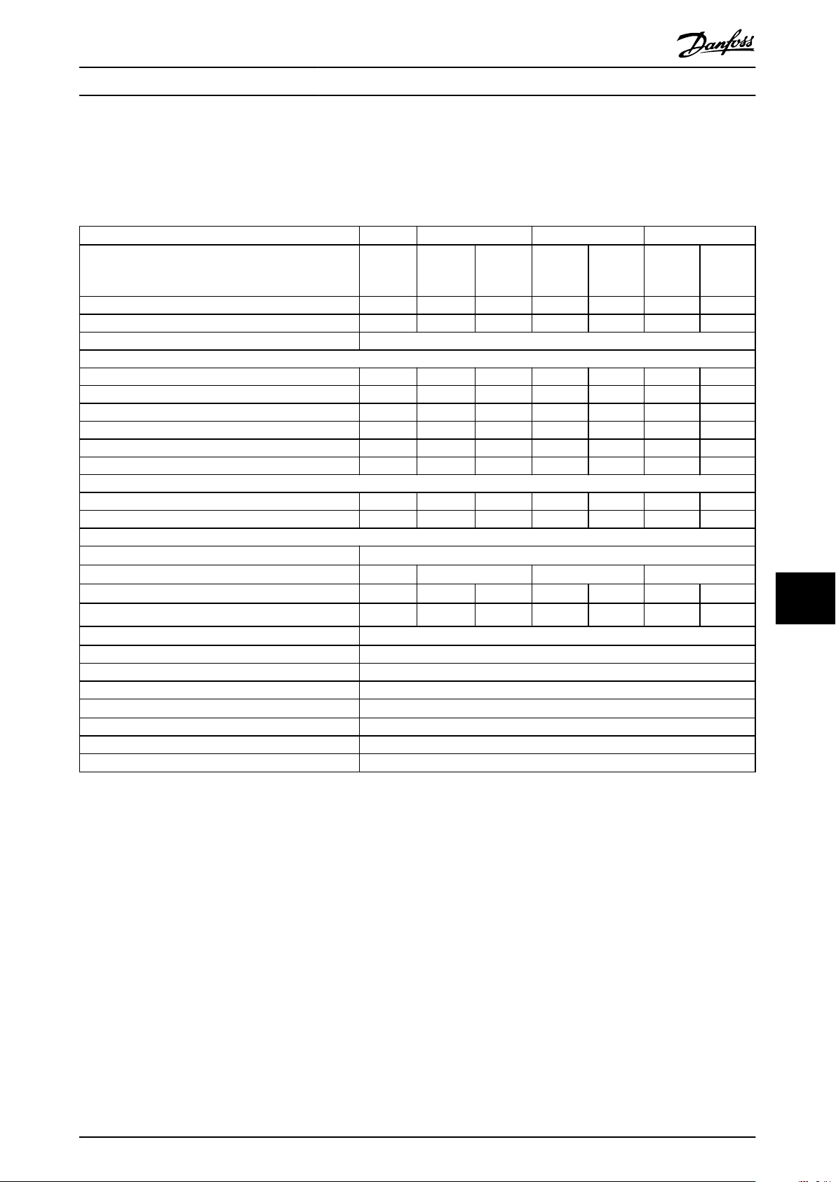
Specications Operating Guide
10 Specications
10.1 Electrical Data, 380-480 V
VLT® AutomationDrive FC 361
High/normal overload NO HO NO HO NO HO NO
(High overload=150% current during 60 s, normal
overload=110% current during 60 s)
Typical shaft output at 400 V [kW] 90 90 110 110 132 132 160
Typical shaft output at 460 V [hp] 125 125 150 150 200 200 250
Enclosure size J8
Output current (3-phase)
Continuous (at 400 V) [A] 177 177 212 212 260 260 315
Intermittent (60 s overload) (at 400 V) [A] 195 266 233 318 286 390 347
Continuous (at 460 V) [A] 160 160 190 190 240 240 302
Intermittent (60 s overload) (at 460 V) [kVA] 176 240 209 285 264 360 332
Continuous kVA (at 400 V) [kVA] 123 123 147 147 180 180 218
Continuous kVA (at 460 V) [kVA] 127 127 151 151 191 191 241
Maximum input current
Continuous (at 400 V) [A] 171 171 204 204 251 251 304
Continuous (at 460 V) [A] 154 154 183 183 231 231 291
Maximum number and size of cables per phase
Mains, motor, brake, and load share [mm2 (AWG)]
Maximum external mains fuses [A]
Estimated power loss at 400 V [W]
Estimated power loss at 460 V [W]
Eciency
Output frequency [Hz] 0–590
Heat sink overtemperature trip [°C (°F)]
Weight, enclosure protection rating IP20 kg (lbs) 101.2 (223.1)
Eciency
Output frequency [Hz] 0–590
Heat sink overtemperature trip [°C (°F)]
Control card overtemperature trip [°C (°F)]
3)
3)
1)
2), 3)
2), 3)
N90K N110 N132 N160
2x95 (2x3/0)
315 315 350 400
2031 2031 2559 2289 2954 2923 3770
1828 1828 2261 2051 2724 2089 3628
0.98
110 (230)
0.98
110 (230)
75 (167)
10 10
Table 10.1 Electrical Data for Enclosures J8, Mains Supply 3x380–480 V AC
1) For fuse ratings, see chapter 10.7 Fuses and Circuit Breakers.
2) Typical power loss is at normal conditions and expected to be within ±15% (tolerance relates to variety in voltage and cable conditions). These
values are based on a typical motor eciency (IE/IE3 border line). Lower eciency motors add to the power loss in the drive. Applies for
dimensioning of drive cooling. If the switching frequency is higher than the default setting, the power losses can increase. LCP and typical control
card power consumptions are included. For power loss data according to EN 50598-2, refer to drives.danfoss.com/knowledge-center/energy-
eciency-directive/#/. Options and customer load can add up to 30 W to the losses, though usually a fully loaded control card and options for
slots A and B each add only 4 W.
3) Measured using 5 m (16.4 ft) shielded motor cables at rated load and rated frequency. Eciency measured at nominal current. For energy
eciency class, see chapter 10.4 Ambient Conditions. For part load losses, see drives.danfoss.com/knowledge-center/energy-eciency-directive/#/.
MG06I102 Danfoss A/S © 06/2018 All rights reserved. 57
Page 60

Specications VLT® AutomationDrive FC 361
VLT® AutomationDrive FC 361
High/normal overload HO NO HO NO HO NO
(High overload=150% current during 60 s, normal
overload=110% current during 60 s)
Typical shaft output at 400 V [kW] 160 200 200 250 250 315
Typical shaft output at 460 V [hp] 250 300 300 350 350 450
Enclosure size J9
Output current (3-phase)
Continuous (at 400 V) [A] 315 395 395 480 480 588
Intermittent (60 s overload) (at 400 V)[A] 473 435 593 528 720 647
Continuous (at 460 V) [A] 302 361 361 443 443 535
Intermittent (60 s overload) (at 460 V) [kVA] 453 397 542 487 665 589
Continuous kVA (at 400 V) [kVA] 218 274 274 333 333 407
Continuous kVA (at 460 V) [kVA] 241 288 288 353 353 426
Maximum input current
Continuous (at 400 V) [A] 304 381 381 463 463 567
Continuous (at 460 V) [A] 291 348 348 427 427 516
Maximum number and size of cables per phase
Mains, motor, brake, and load share [mm2 (AWG)]
Maximum external mains fuses [A]
Estimated power loss at 400 V [W]
Estimated power loss at 460 V [W]
Eciency
Output frequency [Hz] 0–590
Heat sink overtemperature trip [°C (°F)]
1010
Weight, enclosure protection rating IP20 kg (lbs) 168.6 (371.6)
Eciency
Output frequency [Hz] 0–590
Heat sink overtemperature trip [°C (°F)]
Control card overtemperature trip [°C (°F)]
3)
3)
1)
2), 3)
2), 3)
N200 N250 N315
2x185 (2x350 mcm)
550 630 800
3093 4116 4039 5137 5004 6674
2872 3569 3575 4566 4458 5714
0.98
110 (230)
0.98
110 (230)
80 (176)
Table 10.2 Electrical Data for Enclosures J9, Mains Supply 3x380–480 V AC
1) For fuse ratings, see chapter 10.7 Fuses and Circuit Breakers.
2) Typical power loss is at normal conditions and expected to be within ±15% (tolerance relates to variety in voltage and cable conditions). These
values are based on a typical motor eciency (IE/IE3 border line). Lower eciency motors add to the power loss in the drive. Applies for
dimensioning of drive cooling. If the switching frequency is higher than the default setting, the power losses can increase. LCP and typical control
card power consumptions are included. For power loss data according to EN 50598-2, refer to drives.danfoss.com/knowledge-center/energy-
eciency-directive/#/. Options and customer load can add up to 30 W to the losses, though usually a fully loaded control card and options for
slots A and B each add only 4 W.
3) Measured using 5 m (16.4 ft) shielded motor cables at rated load and rated frequency. Eciency measured at nominal current. For energy
eciency class, see chapter 10.4 Ambient Conditions. For part load losses, see drives.danfoss.com/knowledge-center/energy-eciency-directive/#/.
Mains Supply
10.2
Mains supply (L1, L2, L3)
Supply voltage 380–480 V ±10%
Mains voltage low/mains voltage drop-out:
During low mains voltage or a mains drop-out, the drive continues until the DC-link voltage drops below the minimum stop
level, which corresponds typically to 15% below the lowest rated supply voltage of the drive. Power-up and full torque cannot be
expected at mains voltage lower than 10% below the lowest rated supply voltage of the drive.
Supply frequency 50/60 Hz ±5%
Maximum imbalance temporary between mains phases 3.0% of rated supply voltage
True power factor (λ) ≥0.9 nominal at rated load
Displacement power factor (cos Φ) near unity (>0.98)
1)
58 Danfoss A/S © 06/2018 All rights reserved. MG06I102
Page 61

Specications Operating Guide
Switching on input supply L1, L2, L3 (power ups) Maximum 1 time/2 minute
Environment according to EN60664-1 Overvoltage category III/pollution degree 2
The drive is suitable for use on a circuit capable of delivering up to 100 kA short circuit current rating (SCCR) at 480/600 V.
1) Calculations based on IEC61800-3.
10.3 Motor Output and Motor Data
Motor output (U, V, W)
Output voltage 0–100% of supply voltage
Output frequency 0–590 Hz
Output frequency in ux mode 0–300 Hz
Switching on output Unlimited
Ramp times 0.01–3600 s
1) Dependent on voltage and power.
Torque characteristics
Starting torque (constant torque) Maximum 150% for 60 s
Overload torque (constant torque) Maximum 150% for 60 s
1) Percentage relates to the nominal current of the drive.
2) Once every 10 minutes.
1), 2)
1), 2)
1)
10.4 Ambient Conditions
Environment
J8/J9 enclosure IP20/Chassis
Vibration test (standard/ruggedized) 0.7 g/1.0 g
Relative humidity 5%–95% (IEC 721-3-3; Class 3K3 (non-condensing) during operation)
Aggressive environment (IEC 60068-2-43) H2S test Class Kd
Aggressive gases (IEC 60721-3-3) Class 3C3
Test method according to IEC 60068-2-43 H2S (10 days)
Ambient temperature (at SFAVM switching mode)
- with derating Maximum 55 °C (131 °F)
- with full output power of typical EFF2 motors (up to 90% output current) Maximum 50 °C (122 °F)
- at full continuous FC output current Maximum 45 °C (113 °F)
Minimum ambient temperature during full-scale operation 0 °C (32 °F)
Minimum ambient temperature at reduced performance -10 °C (14 °F)
Temperature during storage/transport -25 to +65/70 °C (13 to 149/158 °F)
Maximum altitude above sea level without derating 1000 m (3281 ft)
Maximum altitude above sea level with derating 3000 m (9842 ft)
1) For more information on derating, see the design guide.
EMC standards, Emission EN 61800-3
EMC standards, Immunity EN 61800-3
Energy eciency class
1) Determined according to EN 50598-2 at:
Rated load.
•
90% rated frequency.
•
Switching frequency factory setting.
•
Switching pattern factory setting.
•
1)
IE2
10 10
1)
1)
1)
MG06I102 Danfoss A/S © 06/2018 All rights reserved. 59
Page 62

Specications VLT® AutomationDrive FC 361
10.5 Cable Specications
Cable lengths and cross-sections for control cables
Maximum motor cable length, shielded 150 m (492 ft)
Maximum motor cable length, unshielded 300 m (984 ft)
Maximum cross-section to motor, mains, load sharing, and brake See chapter 10.1 Electrical Data, 380-480 V
Maximum cross-section to control terminals, rigid wire 1.5 mm2/16 AWG (2x0.75 mm2)
Maximum cross-section to control terminals, exible cable 1 mm2/18 AWG
Maximum cross-section to control terminals, cable with enclosed core 0.5 mm2/20 AWG
Minimum cross-section to control terminals 0.25 mm2/23 AWG
1) For power cables, see electrical data in chapter 10.1 Electrical Data, 380-480 V.
1)
10.6 Control Input/Output and Control Data
Digital inputs
Programmable digital inputs 4 (6)
Terminal number 18, 19, 271), 291), 32, 33
Logic PNP or NPN
Voltage level 0–24 V DC
Voltage level, logic 0 PNP <5 V DC
Voltage level, logic 1 PNP >10 V DC
Voltage level, logic 0 NPN >19 V DC
Voltage level, logic 1 NPN <14 V DC
Maximum voltage on input 28 V DC
Input resistance, R
1010
All digital inputs are galvanically isolated from the supply voltage (PELV) and other high-voltage terminals.
1) Terminals 27 and 29 can also be programmed as outputs.
i
Approximately 4 kΩ
Analog inputs
Number of analog inputs 2
Terminal number 53, 54
Modes Voltage or current
Mode select Switches A53 and A54
Voltage mode Switch A53/A54=(U)
Voltage level 0 V to +10 V (scaleable)
Input resistance, R
Maximum voltage ±20 V
Current mode Switch A53/A54=(I)
Current level 0/4 to 20 mA (scaleable)
Input resistance, R
Maximum current 30 mA
Resolution for analog inputs 10 bit (+ sign)
Accuracy of analog inputs Maximum error 0.5% of full scale
Bandwidth 100 Hz
The analog inputs are galvanically isolated from the supply voltage (PELV) and other high-voltage terminals.
i
i
Approximately 10 kΩ
Approximately 200 Ω
60 Danfoss A/S © 06/2018 All rights reserved. MG06I102
Page 63
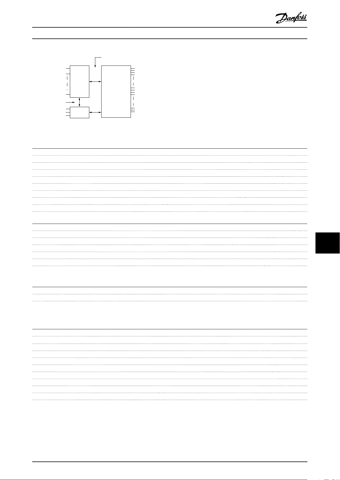
Mains
Functional
isolation
PELV isolation
Motor
DC-bus
High
voltage
Control
+24 V
RS485
18
37
130BA117.10
Specications Operating Guide
Illustration 10.1 PELV Isolation
Pulse inputs
Programmable pulse inputs 2
Terminal number pulse 29, 33
Maximum frequency at terminal 29, 33 (push-pull driven) 110 kHz
Maximum frequency at terminal 29, 33 (open collector) 5 kHz
Minimum frequency at terminal 29, 33 4 Hz
Voltage level See Digital Inputs in chapter 10.6 Control Input/Output and Control Data
Maximum voltage on input 28 V DC
Input resistance, R
i
Approximately 4 kΩ
Pulse input accuracy (0.1–1 kHz) Maximum error: 0.1% of full scale
Analog output
Number of programmable analog outputs 1
Terminal number 42
Current range at analog output 0/4–20 mA
Maximum resistor load to common at analog output 500 Ω
Accuracy on analog output Maximum error: 0.8% of full scale
Resolution on analog output 8 bit
The analog output is galvanically isolated from the supply voltage (PELV) and other high-voltage terminals.
Control card, RS485 serial communication
Terminal number 68 (P, TX+, RX+), 69 (N, TX-, RX-)
Terminal number 61 Common for terminals 68 and 69
The RS485 serial communication circuit is functionally separated from other central circuits and galvanically isolated from the
supply voltage (PELV).
Digital output
Programmable digital/pulse outputs 2
Terminal number 27, 29
Voltage level at digital/frequency output 0–24 V
Maximum output current (sink or source) 40 mA
Maximum load at frequency output 1 kΩ
Maximum capacitive load at frequency output 10 nF
Minimum output frequency at frequency output 0 Hz
Maximum output frequency at frequency output 32 kHz
Accuracy of frequency output Maximum error: 0.1% of full scale
Resolution of frequency outputs 12 bit
1) Terminals 27 and 29 can also be programmed as inputs.
The digital output is galvanically isolated from the supply voltage (PELV) and other high-voltage terminals.
10 10
1)
MG06I102 Danfoss A/S © 06/2018 All rights reserved. 61
Page 64

Specications VLT® AutomationDrive FC 361
Control card, 24 V DC output
Terminal number 12, 13
Maximum load 200 mA
The 24 V DC supply is galvanically isolated from the supply voltage (PELV), but has the same potential as the analog and digital
inputs and outputs.
Relay outputs
Programmable relay outputs 2
Maximum cross-section to relay terminals 2.5 mm2 (12 AWG)
Minimum cross-section to relay terminals 0.2 mm2 (30 AWG)
Length of stripped wire 8 mm (0.3 in)
Relay 01 terminal number 1–3 (break), 1–2 (make)
Maximum terminal load (AC-1)1) on 1–2 (NO) (Resistive load)
Maximum terminal load (AC-15)1) on 1–2 (NO) (Inductive load @ cosφ 0.4) 240 V AC, 0.2 A
Maximum terminal load (DC-1)1) on 1–2 (NO) (Resistive load) 80 V DC, 2 A
Maximum terminal load (DC-13)1) on 1–2 (NO) (Inductive load) 24 V DC, 0.1 A
Maximum terminal load (AC-1)1) on 1–3 (NC) (Resistive load) 240 V AC, 2 A
Maximum terminal load (AC-15)1) on 1–3 (NC) (Inductive load @ cosφ 0.4) 240 V AC, 0.2 A
Maximum terminal load (DC-1)1) on 1–3 (NC) (Resistive load) 50 V DC, 2 A
Maximum terminal load (DC-13)1) on 1–3 (NC) (Inductive load) 24 V DC, 0.1 A
Minimum terminal load on 1–3 (NC), 1–2 (NO) 24 V DC 10 mA, 24 V AC 2 mA
Environment according to EN 60664-1 Overvoltage category III/pollution degree 2
Relay 02 terminal number 4–6 (break), 4–5 (make)
Maximum terminal load (AC-1)1) on 4–5 (NO) (Resistive load)
Maximum terminal load (AC-15)1) on 4–5 (NO) (Inductive load @ cosφ 0.4) 240 V AC, 0.2 A
1010
Maximum terminal load (DC-1)1) on 4–5 (NO) (Resistive load) 80 V DC, 2 A
Maximum terminal load (DC-13)1) on 4–5 (NO) (Inductive load) 24 V DC, 0.1 A
Maximum terminal load (AC-1)1) on 4–6 (NC) (Resistive load) 240 V AC, 2 A
Maximum terminal load (AC-15)1) on 4–6 (NC) (Inductive load @ cosφ 0.4) 240 V AC, 0.2 A
Maximum terminal load (DC-1)1) on 4–6 (NC) (Resistive load) 50 V DC, 2 A
Maximum terminal load (DC-13)1) on 4–6 (NC) (Inductive load) 24 V DC, 0.1 A
Minimum terminal load on 4–6 (NC), 4–5 (NO) 24 V DC 10 mA, 24 V AC 2 mA
Environment according to EN 60664-1 Overvoltage category III/pollution degree 2
The relay contacts are galvanically isolated from the rest of the circuit by reinforced isolation (PELV).
1) IEC 60947 part 4 and 5.
2) Overvoltage Category II.
2), 3)
2), 3)
400 V AC, 2 A
400 V AC, 2 A
Control card, +10 V DC output
Terminal number 50
Output voltage 10.5 V ±0.5 V
Maximum load 25 mA
The 10 V DC supply is galvanically isolated from the supply voltage (PELV) and other high-voltage terminals.
Control characteristics
Resolution of output frequency at 0–1000 Hz ±0.003 Hz
System response time (terminals 18, 19, 27, 29, 32, 33) ≤2 m/s
Speed control range (open loop) 1:100 of synchronous speed
Speed accuracy (open loop) 30–4000 RPM: Maximum error of ±8 RPM
All control characteristics are based on a 4-pole asynchronous motor.
Control card performance
Scan interval 5 M/S
62 Danfoss A/S © 06/2018 All rights reserved. MG06I102
Page 65

Specications Operating Guide
Control card, USB serial communication
USB standard 1.1 (full speed)
USB plug USB type B device plug
NOTICE
Connection to PC is carried out via a standard host/device USB cable.
The USB connection is galvanically isolated from the supply voltage (PELV) and other high-voltage terminals.
The USB connection is not galvanically isolated from ground. Use only isolated laptop/PC as connection to the USB
connector on the drive or an isolated USB cable/converter.
10.7 Fuses and Circuit Breakers
Fuses ensure that possible damage to the drive is limited to damages inside the unit. To ensure compliance with EN 50178,
use the recommended fuses as replacements. Use of fuses on the supply side is mandatory for IEC 60364 (CE) and NEC 2009
(UL) compliant installations.
J8–J9 recommended fuses
Type aR fuses are recommended for enclosures J8–J9. See Table 10.3.
Model 380–480 V
N90K ar-315
N110 ar-315
N132 ar-350
N160 ar-400
N200 ar-500
N250 ar-630
N315 ar-800
Table 10.3 J8–J9 Power/semiconductor Fuse Sizes
10 10
Model Fuse Options
Bussman Littelfuse Littelfuse Bussmann Siba Ferraz-
Shawmut
N90K 170M2619 LA50QS300-4 L50S-300 FWH-300A 20 189 20.315 A50QS300-4 6,9URD31D08A0315
N110 170M2619 LA50QS300-4 L50S-300 FWH-300A 20 189 20.315 A50QS300-4 6,9URD31D08A0315
N132 170M2620 LA50QS350-4 L50S-350 FWH-350A 20 189 20.350 A50QS350-4 6,9URD31D08A0350
N160 170M2621 LA50QS400-4 L50S-400 FWH-400A 20 189 20.400 A50QS400-4 6,9URD31D08A0400
N200 170M4015 LA50QS500-4 L50S-500 FWH-500A 20 610 31.550 A50QS500-4 6,9URD31D08A0550
N250 170M4016 LA50QS600-4 L50S-600 FWH-600A 20 610 31.630 A50QS600-4 6,9URD31D08A0630
N315 170M4017 LA50QS800-4 L50S-800 FWH-800A 20 610 31.800 A50QS800-4 6,9URD32D08A0800
Table 10.4 J8–J9 Power/semiconductor Fuse Options, 380–480 V
Bussmann Rating
LPJ-21/2SP 2.5 A, 600 V
Table 10.5 J8–J9 Space Heater Fuse Recommendation
Ferraz-Shawmut
(Europe)
NOTICE
DISCONNECT SWITCH
All units ordered and supplied with a factory-installed disconnect switch require Class L branch circuit fusing to meet
the 100 kA SCCR for the drive. If a circuit breaker is used, the SCCR rating is 42 kA. The input voltage and power rating
of the drive determines the specic Class L fuse. The input voltage and power rating is found on the product
nameplate. For more information regarding the nameplate, see chapter 4 Mechanical Installation.
MG06I102 Danfoss A/S © 06/2018 All rights reserved. 63
Page 66
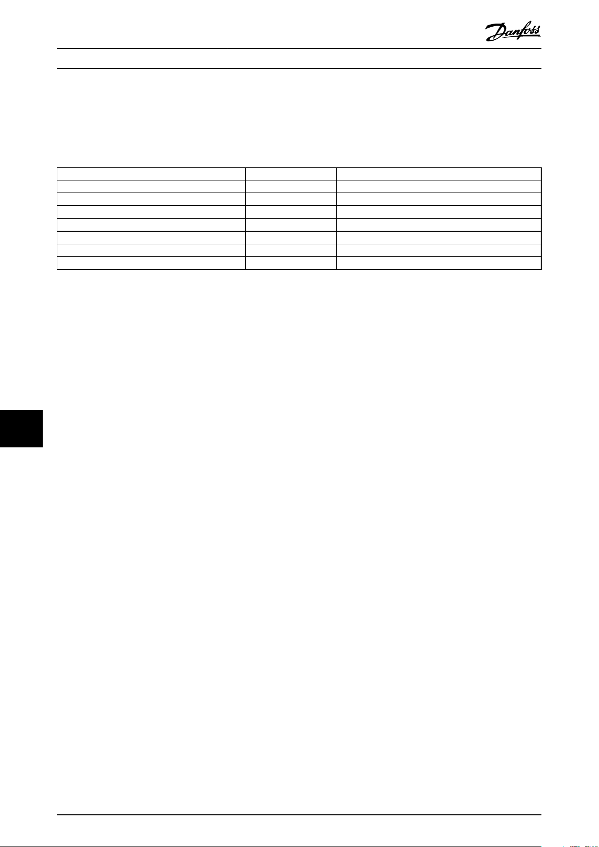
Specications VLT® AutomationDrive FC 361
10.8 Fastener Tightening Torques
Apply the correct torque when tightening fasteners in the locations that are listed in Table 10.6. Too low or too high torque
when fastening an electrical connection results in a bad electrical connection. To ensure correct torque, use a torque
wrench.
Location Bolt size Torque [Nm (in-lb)]
Mains terminals M10/M12 19 (168)/37 (335)
Motor terminals M10/M12 19 (168)/37 (335)
Ground terminals M8/M10 9.6 (84)/19.1 (169)
Load sharing terminals M10/M12 19 (168)/37 (335)
Relay terminals – 0.5 (4)
Door/panel cover M5 2.3 (20)
Gland plate M5 2.3 (20)
Table 10.6 Fastener Torque Ratings
1010
64 Danfoss A/S © 06/2018 All rights reserved. MG06I102
Page 67
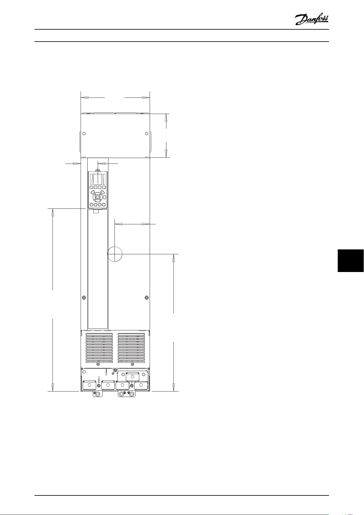
250 (9.8)
160 (6.3)
61 (2.4)
128 (5.0)
495 (19.5)
660 (26.0)
e30bg596.10
Specications Operating Guide
10.9 Enclosure Dimensions
10.9.1 J8 Exterior Dimensions
10 10
Illustration 10.2 Front View of J8
MG06I102 Danfoss A/S © 06/2018 All rights reserved. 65
Page 68

148 (5.8)
844 (33.2)
20 (0.8)
18 (0.7)
60 (2.4)
133 (5.2)
157 (6.2)
64 (2.5)
82 (3.2)
375 (14.8)
201 (7.9)
e30bg597.10
Specications VLT® AutomationDrive FC 361
1010
Illustration 10.3 Side View of J8
66 Danfoss A/S © 06/2018 All rights reserved. MG06I102
Page 69
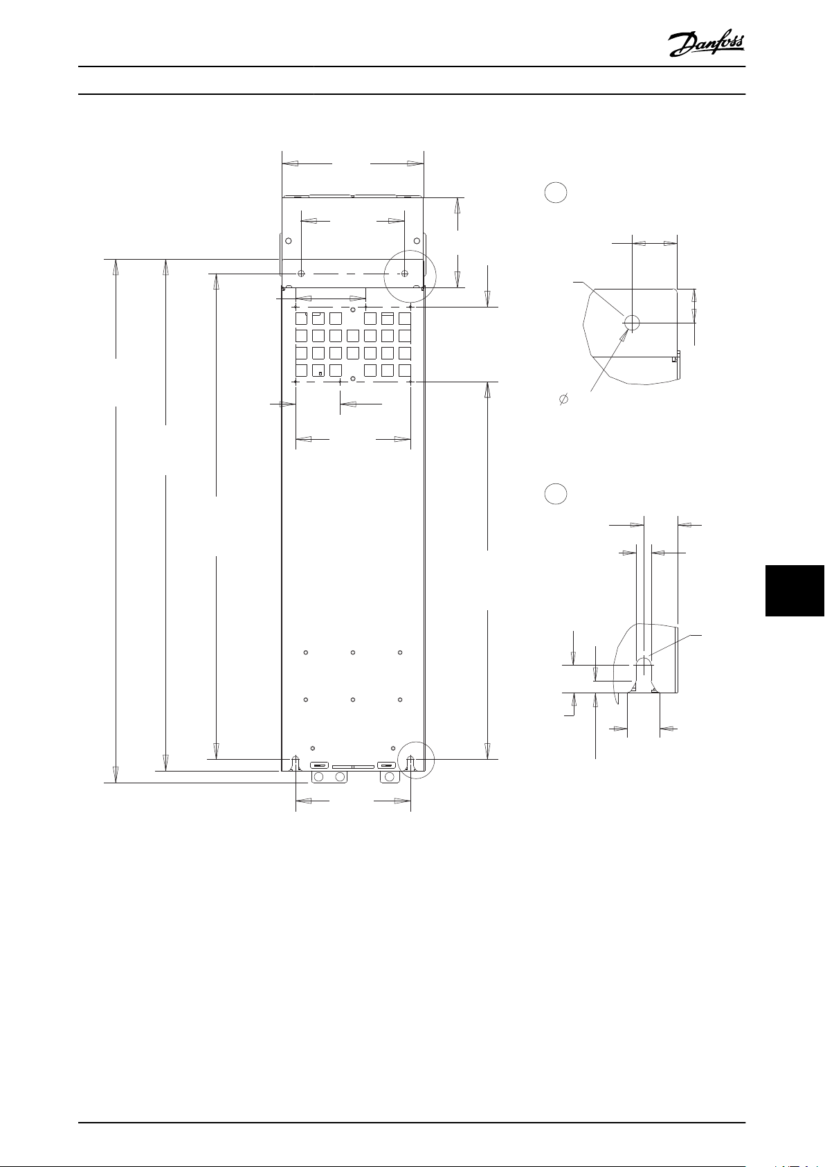
180 (7.1)
A
B
122.5 (4.8)
77.5 (3.1)
200 (7.9)
130 (5.1)
656 (25.8)
200 (7.9)
909 (35.8)
889 (35.0)
844 (33.2)
e30bg598.10
A
B
33 (1.3)
11 (0.4)
25 (1.0)
11 (0.4)
20 (0.8)
9 (0.3)
24
(0.9)
25 (1.0)
M10
M10
250 (9.8)
160 (6.3)
Specications Operating Guide
Illustration 10.4 Back View of J8
10 10
MG06I102 Danfoss A/S © 06/2018 All rights reserved. 67
Page 70
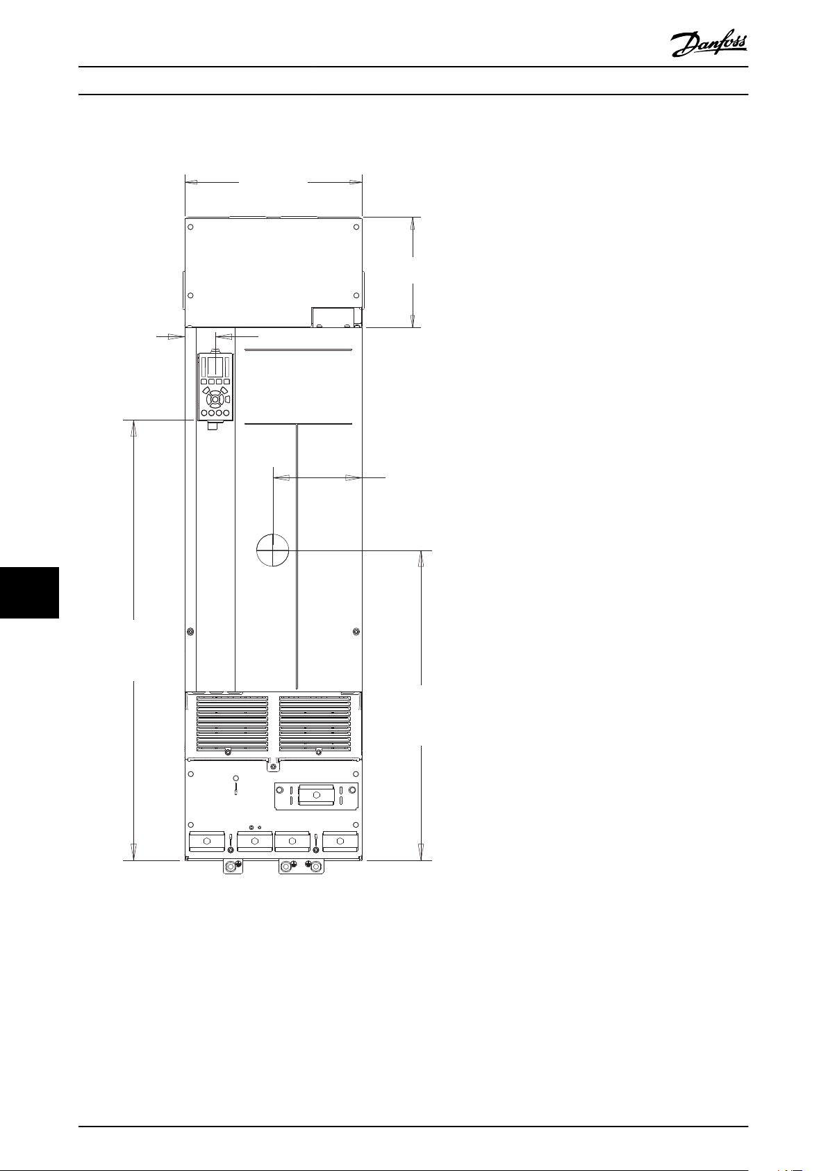
350 (13.8)
218 (8.6)
e30bg599.10
59 (2.3)
176 (6.9)
611 (24.1)
868 (34.2)
Specications VLT® AutomationDrive FC 361
10.9.2 J9 Enclosure Dimensions
1010
Illustration 10.5 Front View of J9
68 Danfoss A/S © 06/2018 All rights reserved. MG06I102
Page 71

142 (5.6)
64 (2.5)
20 (0.8)
18 (0.7)
148 (5.8)1050 (41.3)
203 (8.0)
246 (9.7)
e30bg600.10
75 (3.0)
375 (14.8)
104
(4.1)
Specications Operating Guide
Illustration 10.6 Side View for J9
10 10
MG06I102 Danfoss A/S © 06/2018 All rights reserved. 69
Page 72
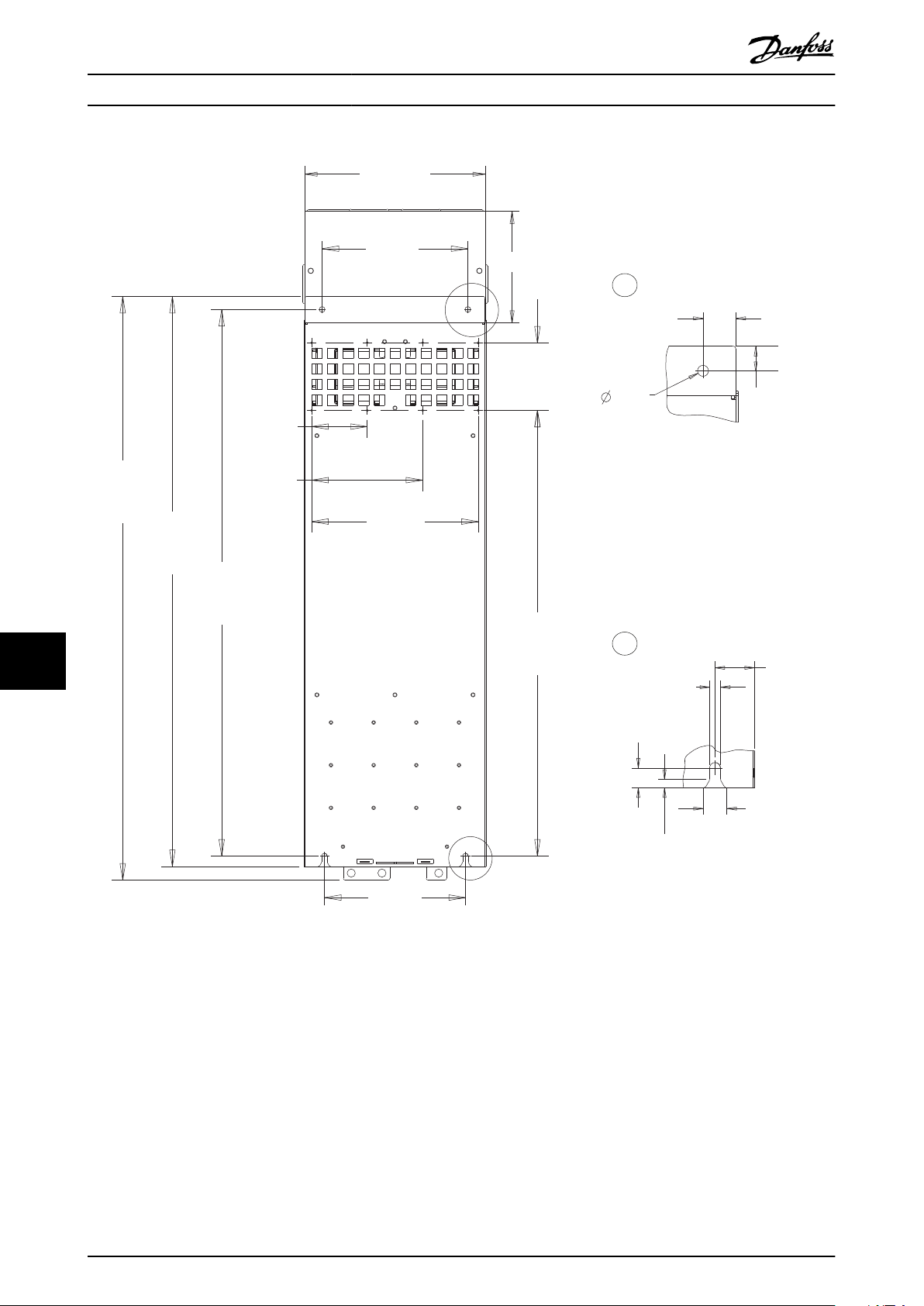
e30bg601.10
350 (13.8)
218 (8.6)
280 (11.0)
A
B
130 (5.1)
857 (33.7)
1122 (44.2)
1096 (43.1)
1051 (41.4)
271 (10.1)
107 (4.2)
213 (8.4)
320 (12.6)
B
A
25 (1.0)
33 (1.3)
11 (0.4)
40
(1.6)
11 (0.4)
9 (0.3)
20 (0.8)
24 (0.9)
Specications VLT® AutomationDrive FC 361
1010
Illustration 10.7 Back View for J9
70 Danfoss A/S © 06/2018 All rights reserved. MG06I102
Page 73

Appendix Operating Guide
11 Appendix
11.1 Abbreviations and Conventions
°C
°F
Ω
AC Alternating current
AEO Automatic energy optimization
ACP Application control processor
AMA Automatic motor adaptation
AWG American wire gauge
CPU Central processing unit
CSIV Customer-specic initialization values
CT Current transformer
DC Direct current
DVM Digital voltmeter
EEPROM
EMC Electromagnetic compatibility
EMI Electromagnetic interference
ESD Electrostatic discharge
ETR Electronic thermal relay
f
M,N
HF High frequency
HVAC Heating, ventilation, and air conditioning
Hz Hertz
I
LIM
I
INV
I
M,N
I
VLT,MAX
I
VLT,N
IEC International electrotechnical commission
IGBT Insulated-gate bipolar transistor
I/O Input/output
IP Ingress protection
kHz Kilohertz
kW Kilowatt
L
d
L
q
LC Inductor-capacitor
LCP Local control panel
LED Light-emitting diode
LOP Local operation pad
mA Milliamp
MCB Miniature circuit breakers
MCP Motor control processor
mV Millivolts
NEMA National Electrical Manufacturers Association
NTC Negative temperature coecient
P
M,N
PCB Printed circuit board
Degrees Celsius
Degrees Fahrenheit
Ohm
Electrically erasable programmable read-only
memory
Nominal motor frequency
Current limit
Rated inverter output current
Nominal motor current
Maximum output current
Rated output current supplied by the drive
Motor d-axis inductance
Motor q-axis inductance
Nominal motor power
PE Protective earth
PELV Protective extra low voltage
PID Proportional integral derivative
PLC Programmable logic controller
P/N Part number
PROM Programmable read-only memory
PS Power section
PTC Positive temperature coecient
PWM Pulse width modulation
R
s
RAM Random-access memory
RCD Residual current device
Regen Regenerative terminals
RFI Radio frequency interference
RMS
RPM Revolutions per minute
SCR Silicon controlled rectier
SMPS Switch mode power supply
S/N Serial number
T
LIM
U
M,N
V Volt
VVC Voltage vector control
X
h
Table 11.1 Abbreviations, Acronyms, and Symbols
Stator resistance
Root means square (cyclically alternating electric
current)
Torque limit
Nominal motor voltage
Motor main reactance
Conventions
Numbered lists indicate procedures.
•
Bullet lists indicate other information and
•
description of illustrations.
Italicized text indicates:
•
- Cross reference
- Link
- Footnote
- Parameter name
- Parameter group name
- Parameter option
All dimensions are in mm (inch).
•
Parameter Menu Structure
11.2
11 11
MG06I102 Danfoss A/S © 06/2018 All rights reserved. 71
Page 74
Appendix VLT® AutomationDrive FC 361
5-18 Terminal X30/4 Digital Input
3-90 Step Size
5-3* Digital Outputs
5-30 Terminal 27 Digital Output
3-91 Ramp Time
3-92 Power Restore
5-32 Term X30/6 Digi Out (MCB 101)
5-31 Terminal 29 Digital Output
3-93 Maximum Limit
3-94 Minimum Limit
5-33 Term X30/7 Digi Out (MCB 101)
3-95 Ramp Delay
5-4* Relays
5-40 Function Relay
4-** Limits / Warnings
4-1* Motor Limits
5-41 On Delay, Relay
4-10 Motor Speed Direction
5-42 O Delay, Relay
4-11 Motor Speed Low Limit [RPM]
5-5* Pulse Input
4-12 Motor Speed Low Limit [Hz]
5-52 Term. 29 Low Ref./Feedb. Value
4-16 Torque Limit Motor Mode
5-53 Term. 29 High Ref./Feedb. Value
4-17 Torque Limit Generator Mode
5-54 Pulse Filter Time Constant #29
4-18 Current Limit
5-55 Term. 33 Low Frequency
4-19 Max Output Frequency
4-21 Speed Limit Factor Source
4-2* Limit Factors
4-20 Torque Limit Factor Source
5-50 Term. 29 Low Frequency
5-51 Term. 29 High Frequency
4-13 Motor Speed High Limit [RPM]
4-14 Motor Speed High Limit [Hz]
4-3* Motor Fb Monitor
5-6* Pulse Output
5-60 Terminal 27 Pulse Output Variable
4-30 Motor Feedback Loss Function
4-31 Motor Feedback Speed Error
5-62 Pulse Output Max Freq #27
4-32 Motor Feedback Loss Timeout
5-57 Term. 33 Low Ref./Feedb. Value
5-58 Term. 33 High Ref./Feedb. Value
5-59 Pulse Filter Time Constant #33
5-56 Term. 33 High Frequency
5-63 Terminal 29 Pulse Output Variable
4-4* Speed Monitor
5-65 Pulse Output Max Freq #29
4-40 Warning Freq. Low
5-66 Terminal X30/6 Pulse Output Variable
4-41 Warning Freq. High
5-68 Pulse Output Max Freq #X30/6
5-7* 24V Encoder Input
4-43 Motor Speed Monitor Function
4-44 Motor Speed Monitor Max
5-71 Term 32/33 Encoder Direction
5-70 Term 32/33 Pulses Per Revolution
4-45 Motor Speed Monitor Timeout
4-5* Adj. Warnings
5-9* Bus Controlled
4-50 Warning Current Low
5-90 Digital & Relay Bus Control
4-51 Warning Current High
5-96 Pulse Out #29 Timeout Preset
5-97 Pulse Out #X30/6 Bus Control
5-93 Pulse Out #27 Bus Control
4-56 Warning Feedback Low
4-55 Warning Reference High
4-54 Warning Reference Low
4-52 Warning Speed Low
4-53 Warning Speed High
4-57 Warning Feedback High
6-** Analog In/Out
4-58 Missing Motor Phase Function
6-00 Live Zero Timeout Time
6-0* Analog I/O Mode
4-6* Speed Bypass
4-60 Bypass Speed From [RPM]
6-01 Live Zero Timeout Function
4-61 Bypass Speed From [Hz]
6-1* Analog Input 1
4-62 Bypass Speed To [RPM]
5-98 Pulse Out #X30/6 Timeout Preset
5-95 Pulse Out #29 Bus Control
5-94 Pulse Out #27 Timeout Preset
6-11 Terminal 53 High Voltage
6-10 Terminal 53 Low Voltage
4-63 Bypass Speed To [Hz]
5-** Digital In/Out
6-13 Terminal 53 High Current
6-12 Terminal 53 Low Current
5-0* Digital I/O mode
5-00 Digital I/O Mode
6-14 Terminal 53 Low Ref./Feedb. Value
5-01 Terminal 27 Mode
6-15 Terminal 53 High Ref./Feedb. Value
5-02 Terminal 29 Mode
6-16 Terminal 53 Filter Time Constant
6-2* Analog Input 2
5-1* Digital Inputs
5-10 Terminal 18 Digital Input
6-21 Terminal 54 High Voltage
6-20 Terminal 54 Low Voltage
5-12 Terminal 27 Digital Input
5-11 Terminal 19 Digital Input
6-22 Terminal 54 Low Current
5-13 Terminal 29 Digital Input
6-23 Terminal 54 High Current
5-14 Terminal 32 Digital Input
6-24 Terminal 54 Low Ref./Feedb. Value
5-15 Terminal 33 Digital Input
6-25 Terminal 54 High Ref./Feedb. Value
5-16 Terminal X30/2 Digital Input
6-26 Terminal 54 Filter Time Constant
5-17 Terminal X30/3 Digital Input
1111
2-10 Brake Function
2-19 Over-voltage Gain
2-17 Over-voltage Control
2-16 AC brake Max. Current
3-** Reference / Ramps
3-0* Reference Limits
3-00 Reference Range
3-01 Reference/Feedback Unit
3-04 Reference Function
3-02 Minimum Reference
3-03 Maximum Reference
3-12 Catch up/slow Down Value
3-1* References
3-10 Preset Reference
3-11 Jog Speed [Hz]
3-16 Reference Resource 2
3-17 Reference Resource 3
3-13 Reference Site
3-14 Preset Relative Reference
3-18 Relative Scaling Reference Resource
3-15 Reference Resource 1
3-19 Jog Speed [RPM]
3-4* Ramp 1
3-40 Ramp 1 Type
3-41 Ramp 1 Ramp Up Time
3-42 Ramp 1 Ramp Down Time
3-47 Ramp 1 S-ramp Ratio at Decel. Start
3-48 Ramp 1 S-ramp Ratio at Decel. End
3-45 Ramp 1 S-ramp Ratio at Accel. Start
3-46 Ramp 1 S-ramp Ratio at Accel. End
3-5* Ramp 2
3-50 Ramp 2 Type
3-51 Ramp 2 Ramp Up Time
3-52 Ramp 2 Ramp Down Time
3-57 Ramp 2 S-ramp Ratio at Decel. Start
3-58 Ramp 2 S-ramp Ratio at Decel. End
3-55 Ramp 2 S-ramp Ratio at Accel. Start
3-56 Ramp 2 S-ramp Ratio at Accel. End
3-67 Ramp 3 S-ramp Ratio at Decel. Start
3-6* Ramp 3
3-60 Ramp 3 Type
3-61 Ramp 3 Ramp up Time
3-62 Ramp 3 Ramp down Time
3-68 Ramp 3 S-ramp Ratio at Decel. End
3-65 Ramp 3 S-ramp Ratio at Accel. Start
3-66 Ramp 3 S-ramp Ratio at Accel. End
3-7* Ramp 4
3-70 Ramp 4 Type
3-71 Ramp 4 Ramp up Time
3-72 Ramp 4 Ramp Down Time
3-77 Ramp 4 S-ramp Ratio at Decel. Start
3-78 Ramp 4 S-ramp Ratio at Decel. End
3-75 Ramp 4 S-ramp Ratio at Accel. Start
3-76 Ramp 4 S-ramp Ratio at Accel. End
3-8* Other Ramps
3-80 Jog Ramp Time
3-81 Quick Stop Ramp Time
3-82 Starting Ramp Up Time
3-9* Digital Pot.Meter
1-3* Adv. Motor Data
1-30 Stator Resistance (Rs)
0-** Operation / Display
0-0* Basic Settings
1-33 Stator Leakage Reactance (X1)
1-34 Rotor Leakage Reactance (X2)
1-31 Rotor Resistance (Rr)
0-01 Language
0-02 Motor Speed Unit
0-04 Operating State at Power-up (Hand)
1-36 Iron Loss Resistance (Rfe)
1-35 Main Reactance (Xh)
0-1* Set-up Operations
0-10 Active Set-up
1-37 d-axis Inductance (Ld)
0-11 Edit Set-up
1-38 q-axis Inductance (Lq)
0-12 This Set-up Linked to
1-39 Motor Poles
1-40 Back EMF at 1000 RPM
0-14 Readout: Edit Set-ups / Channel
0-13 Readout: Linked Set-ups
1-41 Motor Angle Oset
1-46 Position Detection Gain
0-2* LCP Display
0-20 Display Line 1.1 Small
1-47 Torque Calibration
1-5* Load Indep. Setting
0-22 Display Line 1.3 Small
0-21 Display Line 1.2 Small
1-51 Min Speed Normal Magnetising [RPM]
1-50 Motor Magnetisation at Zero Speed
0-24 Display Line 3 Large
0-23 Display Line 2 Large
1-52 Min Speed Normal Magnetising [Hz]
0-25 My Personal Menu
1-56 U/f Characteristic - F
1-55 U/f Characteristic - U
0-30 Unit for User-dened Readout
0-3* LCP Custom Readout
1-58 Flying Start Test Pulses Current
0-32 Max Value of User-dened Readout
0-31 Min Value of User-dened Readout
1-61 High Speed Load Compensation
1-6* Load Depen. Setting
1-60 Low Speed Load Compensation
0-39 Display Text 3
0-37 Display Text 1
0-38 Display Text 2
1-62 Slip Compensation
1-63 Slip Compensation Time Constant
1-65 Resonance Damping Time Constant
1-64 Resonance Damping
0-4* LCP Keypad
0-40 [Hand on] Key on LCP
0-41 [O] Key on LCP
0-42 [Auto on] Key on LCP
1-66 Min. Current at Low Speed
1-7* Start Adjustments
0-43 [Reset] Key on LCP
0-5* Copy/Save
1-70 Start Mode
0-50 LCP Copy
1-71 Start Delay
0-51 Set-up Copy
1-72 Start Function
0-6* Password
1-75 Start Speed [Hz]
1-73 Flying Start
1-74 Start Speed [RPM]
0-60 Main Menu Password
0-61 Access to Main Menu w/o Password
1-** Load and Motor
1-76 Start Current
1-77 Compressor Start Max Speed [RPM]
1-0* General Settings
1-00 Conguration Mode
1-79 Compressor Start Max Time to Trip
1-78 Compressor Start Max Speed [Hz]
1-01 Motor Control Principle
1-03 Torque Characteristics
1-82 Min Speed for Function at Stop [Hz]
1-81 Min Speed for Function at Stop [RPM]
1-8* Stop Adjustments
1-80 Function at Stop
1-04 Overload Mode
1-05 Local Mode Conguration
1-06 Clockwise Direction
1-1* Special Settings
1-9* Motor Temperature
1-10 Motor Construction
1-90 Motor Thermal Protection
1-14 Damping Gain
1-93 Thermistor Resource
1-91 Motor External Fan
2-** Brakes
2-0* DC-Brake
2-00 DC Hold Current
1-15 Low Speed Filter Time Const.
1-16 High Speed Filter Time Const.
1-17 Voltage lter time const.
1-18 Min. Current at No Load
1-2* Motor Data
2-01 DC Brake Current
1-20 Motor Power [kW]
2-02 DC Braking Time
1-22 Motor Voltage
1-23 Motor Frequency
2-04 DC Brake Cut In Speed [Hz]
1-24 Motor Current
1-25 Motor Nominal Speed
1-26 Motor Cont. Rated Torque
2-1* Brake Energy Funct.
1-29 Automatic Motor Adaptation (AMA)
2-06 Parking Current
2-07 Parking Time
2-03 DC Brake Cut In Speed [RPM]
1-59 Flying Start Test Pulses Frequency
72 Danfoss A/S © 06/2018 All rights reserved. MG06I102
Page 75

Appendix Operating Guide
14-32 Current Lim Ctrl, Filter Time
14-31 Current Lim Ctrl, Integration Time
14-21 Automatic Restart Time
14-22 Operation Mode
14-24 Trip Delay at Current Limit
14-25 Trip Delay at Torque Limit
14-26 Trip Delay at Inverter Fault
14-30 Current Lim Ctrl, Proportional Gain
14-3* Current Limit Ctrl.
14-41 AEO Minimum Magnetisation
14-4* Energy Optimising
14-40 VT Level
14-42 Minimum AEO Frequency
14-43 Motor Cosphi
14-5* Environment
14-50 RFI Filter
14-51 DC-Link Compensation
14-59 Actual Number of Inverter Units
14-52 Fan Control
14-53 Fan Monitor
14-55 Output Filter
14-62 Inv. Overload Derate Current
14-61 Function at Inverter Overload
14-6* Auto Derate
14-60 Function at Over Temperature
14-8* Options
14-89 Option Detection
14-9* Fault Settings
14-90 Fault Level
15-** Drive Information
15-0* Operating Data
15-01 Running Hours
15-00 Operating hours
15-03 Power Up's
15-02 kWh Counter
15-07 Reset Running Hours Counter
15-04 Over Temp's
15-05 Over Volt's
15-06 Reset kWh Counter
15-1* Data Log Settings
15-10 Logging Source
15-12 Trigger Event
15-13 Logging Mode
15-14 Samples Before Trigger
15-11 Logging Interval
15-22 Historic Log: Time
15-21 Historic Log: Value
15-2* Historic Log
15-20 Historic Log: Event
15-31 Fault Log: Value
15-32 Fault Log: Time
15-3* Fault Log
15-30 Fault Log: Error Code
15-4* Drive Identication
15-40 FC Type
15-41 Power Section
15-42 Voltage
15-43 Software Version
15-44 Ordered Typecode String
12-14 Link Duplex
8-85 Slave Timeout Errors
7-46 Process PID Feed Fwd Normal/ Inv.
12-18 Supervisor MAC
12-19 Supervisor IP Addr.
8-88 Reset FC port Diagnostics
8-9* Bus Jog
Ctrl.
7-48 PCD Feed Forward
12-8* Other Ethernet Ser vices
12-80 FTP Server
8-90 Bus Jog 1 Speed
8-91 Bus Jog 2 Speed
7-49 Process PID Output Normal/ Inv. Ctrl.
7-5* Adv. Process PID II
12-81 HTTP Server
9-** PROFIdrive
7-50 Process PID Extended PID
12-82 SMTP Service
9-00 Setpoint
7-51 Process PID Feed Fwd Gain
12-83 SNMP Agent
9-07 Actual Value
7-52 Process PID Feed Fwd Ramp up
12-85 ACD Last Conict
12-84 Address Conict Detection
12-89 Transparent Socket Channel Port
12-9* Advanced Ethernet Services
12-90 Cable Diagnostic
9-15 PCD Write Conguration
7-53 Process PID Feed Fwd Ramp down
9-22 Telegram Selection
9-16 PCD Read Conguration
9-18 Node Address
9-19 Drive Unit System Number
7-57 Process PID Fb. Filter Time
7-56 Process PID Ref. Filter Time
7-6* Feedback Conversion
7-60 Feedback 1 Conversion
12-92 IGMP Snooping
12-91 Auto Cross Over
9-27 Parameter Edit
9-23 Parameters for Signals
7-62 Feedback 2 Conversion
8-** Comm. and Options
12-94 Broadcast Storm Protection
12-93 Cable Error Length
9-28 Process Control
9-44 Fault Message Counter
8-0* General Settings
8-01 Control Site
12-96 Port Cong
12-95 Inactivity timeout
9-45 Fault Code
9-47 Fault Number
8-03 Control Word Timeout Time
8-02 Control Word Source
12-97 QoS Priority
9-52 Fault Situation Counter
8-04 Control Word Timeout Function
12-98 Interface Counters
9-53 Probus Warning Word
8-05 End-of-Timeout Function
12-99 Media Counters
9-63 Actual Baud Rate
8-06 Reset Control Word Timeout
13-01 Start Event
13-** Smart Logic
13-0* SLC Settings
13-00 SL Controller Mode
9-68 Status Word 1
9-64 Device Identication
9-65 Prole Number
9-67 Control Word 1
8-07 Diagnosis Trigger
8-08 Readout Filtering
8-1* Ctrl. Word Settings
8-10 Control Word Prole
13-03 Reset SLC
13-02 Stop Event
13-1* Comparators
13-10 Comparator Operand
9-70 Edit Set-up
9-71 Probus Save Data Values
9-72 ProbusDriveReset
9-75 DO Identication
8-13 Congurable Status Word STW
8-14 Congurable Control Word CTW
8-19 Product Code
8-3* FC Port Settings
13-44 Logic Rule Boolean 3
13-4* Logic Rules
13-42 Logic Rule Boolean 2
13-40 Logic Rule Boolean 1
13-41 Logic Rule Operator 1
13-5* States
13-51 SL Controller Event
13-52 SL Controller Action
14-** Special Functions
14-0* Inverter Switching
14-00 Switching Pattern
13-12 Comparator Value
13-11 Comparator Operator
13-2* Timers
13-20 SL Controller Timer
14-04 Acoustic Noise Reduction
14-01 Switching Frequency
14-03 Overmodulation
14-06 Dead Time Compensation
14-1* Mains Failure
14-10 Mains Failure
13-43 Logic Rule Operator 2
14-15 Kin. Back-up Trip Recovery Level
14-16 Kin. Back-up Gain
14-14 Kin. Back-up Time-out
14-12 Response to Mains Imbalance
14-11 Mains Fault Voltage Level
14-2* Trip Reset
14-20 Reset Mode
11 11
9-99 Probus Revision Counter
9-93 Changed Parameters (4)
9-80 Dened Parameters (1)
9-81 Dened Parameters (2)
9-82 Dened Parameters (3)
9-83 Dened Parameters (4)
8-30 Protocol
8-31 Address
8-32 FC Port Baud Rate
8-33 Parity / Stop Bits
9-84 Dened Parameters (5)
8-34 Estimated cycle time
9-85 Dened Parameters (6)
8-35 Minimum Response Delay
9-90 Changed Parameters (1)
8-36 Max Response Delay
9-91 Changed Parameters (2)
8-37 Max Inter-Char Delay
8-4* FC MC protocol set
8-40 Telegram Selection
8-41 Parameters for Signals
12-** Ethernet
12-0* IP Settings
12-00 IP Address Assignment
8-42 PCD Write Conguration
8-43 PCD Read Conguration
8-5* Digital/Bus
8-50 Coasting Select
9-94 Changed Parameters (5)
9-92 Changed Parameters (3)
12-01 IP Address
8-51 Quick Stop Select
12-02 Subnet Mask
8-52 DC Brake Select
12-04 DHCP Server
12-05 Lease Expires
12-06 Name Servers
12-07 Domain Name
12-08 Host Name
12-03 Default Gateway
8-53 Start Select
8-54 Reversing Select
8-55 Set-up Select
12-09 Physical Address
12-1* Ethernet Link Parameters
8-57 Prodrive OFF2 Select
8-56 Preset Reference Select
8-58 Prodrive OFF3 Select
8-8* FC Port Diagnostics
8-80 Bus Message Count
12-10 Link Status
8-81 Bus Error Count
12-11 Link Duration
8-82 Slave Messages Rcvd
12-13 Link Speed
12-12 Auto Negotiation
8-84 Slave Messages Sent
8-83 Slave Error Count
6-3* Analog Input 3
6-30 Terminal X30/11 Low Voltage
6-31 Terminal X30/11 High Voltage
6-34 Term. X30/11 Low Ref./Feedb. Value
6-35 Term. X30/11 High Ref./Feedb. Value
6-36 Term. X30/11 Filter Time Constant
6-4* Analog Input 4
6-40 Terminal X30/12 Low Voltage
6-41 Terminal X30/12 High Voltage
6-44 Term. X30/12 Low Ref./Feedb. Value
6-45 Term. X30/12 High Ref./Feedb. Value
6-46 Term. X30/12 Filter Time Constant
6-5* Analog Output 1
6-50 Terminal 42 Output
6-51 Terminal 42 Output Min Scale
6-52 Terminal 42 Output Max Scale
6-54 Terminal 42 Output Timeout Preset
6-6* Analog Output 2
6-60 Terminal X30/8 Output
6-61 Terminal X30/8 Min. Scale
6-62 Terminal X30/8 Max. Scale
6-64 Terminal X30/8 Output Timeout Preset
6-63 Terminal X30/8 Bus Control
7-** Controllers
7-0* Speed PID Ctrl.
7-02 Speed PID Proportional Gain
7-00 Speed PID Feedback Source
6-55 Analog Output Filter
6-53 Term 42 Output Bus Ctrl
7-03 Speed PID Integral Time
7-04 Speed PID Dierentiation Time
7-05 Speed PID Di. Gain Limit
7-06 Speed PID Lowpass Filter Time
7-13 Torque PI Integration Time
7-2* Process Ctrl. Feedb
7-22 Process CL Feedback 2 Resource
7-20 Process CL Feedback 1 Resource
7-3* Process PID Ctrl.
7-1* Torque PI Ctrl.
7-12 Torque PI Proportional Gain
7-30 Process PID Normal/ Inverse Control
7-31 Process PID Anti Windup
7-32 Process PID Start Speed
7-33 Process PID Proportional Gain
7-34 Process PID Integral Time
7-08 Speed PID Feed Forward Factor
7-07 Speed PID Feedback Gear Ratio
7-35 Process PID Dierentiation Time
7-36 Process PID Di. Gain Limit
7-38 Process PID Feed Forward Factor
7-39 On Reference Bandwidth
7-40 Process PID I-part Reset
7-4* Adv. Process PID I
7-42 Process PID Output Pos. Clamp
7-41 Process PID Output Neg. Clamp
7-45 Process PID Feed Fwd Resource
7-44 Process PID Gain Scale at Max. Ref.
7-43 Process PID Gain Scale at Min. Ref.
MG06I102 Danfoss A/S © 06/2018 All rights reserved. 73
Page 76

Appendix VLT® AutomationDrive FC 361
1111
[%]
18-92 Process PID Clamped Output
18-93 Process PID Gain Scaled Output
18-91 Process PID Output
16-51 Pulse Reference
16-52 Feedback[Unit]
16-50 External Reference
21-** Ext. Closed Loop
16-53 Digi Pot Reference
21-1* Ext. CL 1 Ref./Fb.
16-57 Feedback [RPM]
21-11 Ext. 1 Minimum Reference
21-10 Ext. 1 Ref./Feedback Unit
16-6* Inputs & Outputs
16-60 Digital Input
21-12 Ext. 1 Maximum Reference
21-13 Ext. 1 Reference Source
16-62 Analog Input 53
16-61 Terminal 53 Switch Setting
21-14 Ext. 1 Feedback Source
21-15 Ext. 1 Setpoint
16-64 Analog Input 54
16-63 Terminal 54 Switch Setting
21-18 Ext. 1 Feedback [Unit]
21-17 Ext. 1 Reference [Unit]
16-65 Analog Output 42 [mA]
16-66 Digital Output [bin]
21-19 Ext. 1 Output [%]
16-67 Freq. Input #29 [Hz]
21-2* Ext. CL 1 PID
16-68 Freq. Input #33 [Hz]
21-24 Ext. 1 Dif. Gain Limit
21-23 Ext. 1 Dierentation Time
21-20 Ext. 1 Normal/Inverse Control
21-21 Ext. 1 Proportional Gain
21-22 Ext. 1 Integral Time
22-** Appl. Functions
22-0* Miscellaneous
22-00 External Interlock Delay
22-4* Sleep Mode
16-72 Counter A
16-73 Counter B
16-75 Analog In X30/11
16-76 Analog In X30/12
16-71 Relay Output [bin]
16-70 Pulse Output #29 [Hz]
16-69 Pulse Output #27 [Hz]
16-77 Analog Out X30/8 [mA]
16-8* Fieldbus & FC Port
22-40 Minimum Run Time
16-80 Fieldbus CTW 1
22-41 Minimum Sleep Time
16-82 Fieldbus REF 1
22-42 Wake-up Speed [RPM]
16-84 Comm. Option STW
22-43 Wake-up Speed [Hz]
22-44 Wake-up Ref./FB Dierence
16-85 FC Port CTW 1
16-86 FC Port REF 1
22-45 Setpoint Boost
16-87 Bus Readout Alarm/Warning
22-46 Maximum Boost Time
22-6* Broken Belt Detection
22-60 Broken Belt Function
16-9* Diagnosis Readouts
16-90 Alarm Word
16-91 Alarm Word 2
22-61 Broken Belt Torque
16-92 Warning Word
22-62 Broken Belt Delay
16-93 Warning Word 2
30-20 High Starting Torque Time [s]
30-** Special Features
30-2* Adv. Start Adjust
16-97 Alarm Word 3
16-94 Ext. Status Word
16-95 Ext. Status Word 2
30-22 Locked Rotor Protection
30-21 High Starting Torque Current [%]
16-98 Warning Word 3
17-** Position Feedback
30-24 Locked Rotor Detection Speed Error
30-23 Locked Rotor Detection Time [s]
17-1* Inc. Enc. Interface
17-10 Signal Type
17-11 Resolution (PPR)
40-** Special Settings
40-4* Extend. Fault Log
17-5* Resolver Interface
17-50 Poles
40-41 Fault Log: Frequency
40-40 Fault Log: Ext. Reference
17-51 Input Voltage
17-52 Input Frequency
40-42 Fault Log: Current
40-43 Fault Log: Voltage
17-56 Encoder Sim. Resolution
17-53 Transformation Ratio
40-45 Fault Log: Control Word
40-44 Fault Log: DC Link Voltage
17-59 Resolver Interface
17-6* Monitoring and App.
40-46 Fault Log: Status Word
17-60 Feedback Direction
17-61 Feedback Signal Monitoring
18-** Data Readouts 2
18-5* Active Alarms/Warnings
18-55 Active Alarm Numbers
18-56 Active Warning Numbers
18-9* PID Readouts
18-90 Process PID Error
16-49 Current Fault Source
15-45 Actual Typecode String
15-46 Frequency Converter Ordering No
15-47 Power Card Ordering No
15-48 LCP Id No
15-54 Cong File Name
15-53 Power Card Serial Number
15-51 Frequency Converter Serial Number
15-50 SW ID Power Card
15-49 SW ID Control Card
15-59 Filename
15-6* Option Ident
15-60 Option Mounted
15-62 Option Ordering No
15-61 Option SW Version
15-63 Option Serial No
15-8* Operating Data II
15-81 Preset Fan Running Hours
15-80 Fan Running Hours
16-22 Torque [%]
16-02 Reference %
16-03 Status Word
15-9* Parameter Info
15-92 Dened Parameters
15-93 Modied Parameters
16-** Data Readouts
16-0* General Status
16-00 Control Word
16-01 Reference [Unit]
16-05 Main Actual Value [%]
16-09 Custom Readout
16-1* Motor Status
16-10 Power [kW]
16-11 Power [hp]
16-12 Motor Voltage
16-16 Torque [Nm]
16-13 Frequency
16-17 Speed [RPM]
16-14 Motor current
16-15 Frequency [%]
16-18 Motor Thermal
16-20 Motor Angle
16-24 Calibrated Stator Resistance
16-21 Torque [%] High Res.
16-3* Drive Status
16-30 DC Link Voltage
16-31 System Temp.
16-34 Heatsink Temp.
16-35 Inverter Thermal
16-36 Inv. Nom. Current
16-40 Logging Buer Full
16-37 Inv. Max. Current
16-38 SL Controller State
16-39 Control Card Temp.
16-48 Speed Ref. After Ramp [RPM]
16-47 Motor Phase W Current
16-46 Motor Phase V Current
16-45 Motor Phase U Current
16-5* Ref. & Feedb.
74 Danfoss A/S © 06/2018 All rights reserved. MG06I102
Page 77

Index Operating Guide
Index
A
Abbreviations......................................................................................... 71
AC mains.................................................................................................. 25
see also Mains
Additional resources.............................................................................. 3
Alarms
List of............................................................................................. 11, 47
Log......................................................................................................... 11
Types of................................................................................................ 46
Ambient conditions
Specications.................................................................................... 59
Analog
Input specications......................................................................... 60
Output specications..................................................................... 61
Analog input/output
Descriptions and default settings.............................................. 32
Approval and certication................................................................... 3
Auto on.............................................................................................. 11, 44
Automatic energy optimization...................................................... 37
Automatic motor adaptation (AMA)
Conguring........................................................................................ 37
Warning............................................................................................... 51
B
Brake
resistor................................................................................................. 47
Burst transient....................................................................................... 21
Bus termination switch....................................................................... 34
C
Cables
Installation warning........................................................................ 17
Maximum number and size per phase..................................... 57
Routing......................................................................................... 31, 35
Shielded............................................................................................... 17
Specications............................................................................. 57, 60
Capacitor storage................................................................................. 13
Circuit breakers...................................................................................... 35
Clearance requirement....................................................................... 14
Condensation......................................................................................... 14
Control
Characteristics................................................................................... 62
Wiring................................................................................................... 21
Control card
Overtemperature trip point......................................................... 57
RS485 specications....................................................................... 61
Specications.................................................................................... 62
Warning............................................................................................... 52
Control input/output
Descriptions and default settings.............................................. 31
Control shelf.............................................................................................. 9
Control wiring.......................................................................... 31, 33, 35
Cooling
Check list............................................................................................. 35
Cooling................................................................................................ 14
Dust warning..................................................................................... 14
Current
Input..................................................................................................... 34
Leakage............................................................................................... 21
Limit...................................................................................................... 56
D
Denitions
Status messages............................................................................... 44
Derating
Specications.................................................................................... 59
Digital
Input specications......................................................................... 60
Output specications..................................................................... 61
Digital input/output
Descriptions and default settings.............................................. 32
Dimension, shipping.............................................................................. 6
Dimensions
J8 exterior........................................................................................... 65
J8 terminal.......................................................................................... 27
J9 exterior........................................................................................... 68
J9 terminal.......................................................................................... 29
Discharge time......................................................................................... 4
Disconnect.............................................................................................. 63
Disconnect switch................................................................................ 36
Disposal instruction............................................................................... 3
Drive
Denition............................................................................................... 6
Initialization....................................................................................... 39
Lifting................................................................................................... 15
Status.................................................................................................... 44
E
Eciency
Specications
Electrical specications 380–480 V................................................ 58
Electronic thermal relay (ETR).......................................................... 17
EMC.............................................................................................. 17, 18, 19
Encoder.................................................................................................... 38
Energy eciency class........................................................................ 59
Environment........................................................................................... 59
Exterior dimensions
J8............................................................................................................ 65
J9............................................................................................................ 68
External alarm reset............................................................................. 42
.................................................................................... 57
MG06I102 Danfoss A/S © 06/2018 All rights reserved. 75
Page 78

Index VLT® AutomationDrive FC 361
Installation
F
Factory default settings...................................................................... 39
Fans
Servicing.............................................................................................. 14
Warning............................................................................................... 53
Fastener torque rating........................................................................ 64
Fault log................................................................................................... 11
Fieldbus.................................................................................................... 31
Filter........................................................................................................... 14
Fuses
Fuse....................................................................................................... 50
Overcurrent protection.................................................................. 17
Pre-start check list........................................................................... 35
Specications.................................................................................... 63
Troubleshooting............................................................................... 56
G
Galvanic isolation................................................................................. 61
Gases......................................................................................................... 14
Ground
Check list............................................................................................. 35
Floating delta.................................................................................... 25
Grounded delta................................................................................ 25
Grounding.......................................................................................... 23
Isolated main..................................................................................... 25
Warning............................................................................................... 51
Ground wire............................................................................................ 21
H
Hand on............................................................................................. 11, 44
Heat sink
Cleaning.............................................................................................. 14
Overtemperature trip point......................................................... 57
Warning........................................................................................ 51, 52
Heater
Usage.................................................................................................... 14
High voltage.................................................................................... 49, 50
High voltage warning............................................................................ 4
Humidity.................................................................................................. 14
I
Indicator lights....................................................................................... 46
Input
Power.................................................................................................... 21
Voltage................................................................................................. 36
Input specications............................................................................. 60
Check list............................................................................................. 35
Electrical.............................................................................................. 17
EMC-compliant................................................................................. 19
Initialization....................................................................................... 39
Qualied personnel........................................................................... 4
Quick setup........................................................................................ 37
Start up................................................................................................ 38
Tools needed..................................................................................... 13
Installation....................................................................................... 14, 16
Installation environment................................................................... 13
Interference
EMC....................................................................................................... 18
Radio....................................................................................................... 6
Interlock device..................................................................................... 33
J
J8 interior view......................................................................................... 7
J9 Interior view......................................................................................... 8
L
LCP
Display................................................................................................. 10
Indicator lights.................................................................................. 11
Menu..................................................................................................... 12
Troubleshooting............................................................................... 54
Leakage current................................................................................ 4, 21
Lifting................................................................................................. 13, 15
Load share
Warning........................................................................................... 4, 50
Local control panel (LCP)................................................................... 10
M
Main menu.............................................................................................. 12
Mains
Supply specications...................................................................... 58
Maintenance.................................................................................... 14, 43
Manual
Version number................................................................................... 3
MCT 10...................................................................................................... 37
Menu
Descriptions of.................................................................................. 12
Keys....................................................................................................... 11
76 Danfoss A/S © 06/2018 All rights reserved. MG06I102
Page 79

Index Operating Guide
Motor
Cable.............................................................................................. 17, 23
Connection......................................................................................... 23
Data....................................................................................................... 56
Output
specications..................................................................... 59
Overheating....................................................................................... 48
Power.................................................................................................... 21
Rotation............................................................................................... 38
Thermistor.......................................................................................... 42
Troubleshooting............................................................................... 55
Unintended motor rotation............................................................ 5
Warning................................................................................. 47, 48, 49
Wiring schematic............................................................................. 20
Mounting.......................................................................................... 14, 16
N
Nameplate............................................................................................... 13
Navigation keys.............................................................................. 11, 36
O
Open loop
Wiring for speed control................................................................ 40
Optional equipment..................................................................... 33, 36
Output
Specications.................................................................................... 61
Overcurrent protection...................................................................... 17
Overvoltage............................................................................................ 56
P
Parameters....................................................................................... 12, 39
PELV........................................................................................................... 61
Periodic forming................................................................................... 13
Phase loss................................................................................................ 47
Pigtails...................................................................................................... 17
Potential equalization......................................................................... 21
Potentiometer........................................................................................ 32
Power
Losses................................................................................................... 57
connection......................................................................................... 17
Ratings................................................................................................. 57
Power card
Warning............................................................................................... 52
Programming......................................................................................... 11
Pulse
Input specications......................................................................... 61
Q
Qualied personnel................................................................................ 4
Quick menu..................................................................................... 11, 12
Ramp-up time........................................................................................ 56
Recycling.................................................................................................... 3
Regen
Terminals............................................................................................. 27
Regional settings.................................................................................. 39
Relay
Specications.................................................................................... 62
Relays
Location............................................................................................... 32
Reset............................................................................................ 11, 46, 52
RFI............................................................................................................... 25
Rotor
Warning............................................................................................... 53
RS485
Conguring........................................................................................ 34
RS485.................................................................................................... 31
Wiring schematic............................................................................. 20
S
Safety instructions................................................................................ 17
Serial communication
Descriptions and default settings.............................................. 31
Service...................................................................................................... 43
Set-up....................................................................................................... 11
Shielding
Clamps................................................................................................. 17
Twisted ends...................................................................................... 17
Shipping dimension............................................................................... 6
Short circuit............................................................................................ 49
Sleep mode............................................................................................. 45
Software version number.................................................................... 3
Specications electrical...................................................................... 57
Start/stop................................................................................................. 41
Status message denitions............................................................... 44
Storage..................................................................................................... 13
Supply voltage....................................................................................... 50
Switches
A53 and A54....................................................................................... 60
A53/A54............................................................................................... 34
Bus termination................................................................................ 34
Disconnect.......................................................................................... 63
T
Temperature........................................................................................... 14
Terminal dimensions
J8............................................................................................................ 27
J9............................................................................................................ 29
Terminal torque rating........................................................................ 64
R
Ramp-down time.................................................................................. 56
MG06I102 Danfoss A/S © 06/2018 All rights reserved. 77
Page 80

Index VLT® AutomationDrive FC 361
Terminals
Analog input/output...................................................................... 32
Control locations.............................................................................. 31
Digital input/output........................................................................ 32
Relays.................................................................................................... 32
Serial communication.................................................................... 31
Terminal 37......................................................................................... 33
Thermistor
Cable routing..................................................................................... 31
Terminal location............................................................................. 32
Wiring congurations..................................................................... 42
Tools.......................................................................................................... 13
Torque
Characteristic..................................................................................... 59
Limit............................................................................................... 48, 56
Transducer............................................................................................... 31
Trip
Points for 380–480 V drives.......................................................... 57
Troubleshooting
Fuses..................................................................................................... 56
LCP......................................................................................................... 54
Mains.................................................................................................... 56
Motor.................................................................................................... 55
Warnings and alarms...................................................................... 47
U
Unintended start.............................................................................. 4, 43
USB
Specications.................................................................................... 63
V
Voltage
Imbalance........................................................................................... 47
Input..................................................................................................... 34
W
Warnings
List of............................................................................................. 11, 47
Types of................................................................................................ 46
Weight......................................................................................................... 6
Windmilling............................................................................................... 5
Wire size................................................................................................... 23
Wiring congurations
External alarm reset........................................................................ 42
Open loop........................................................................................... 40
Start/stop............................................................................................ 41
Thermistor.......................................................................................... 42
Wiring control terminals.................................................................... 33
Wiring schematic
Drive...................................................................................................... 20
Wiring schematic............................................................................. 20
78 Danfoss A/S © 06/2018 All rights reserved. MG06I102
Page 81

Index Operating Guide
MG06I102 Danfoss A/S © 06/2018 All rights reserved. 79
Page 82

Danfoss can accept no responsibility for possible errors in catalogues, brochures and other printed material. Danfoss reserves the right to alter its products without notice. This also applies to
products already on order provided that such alterations can be made without subsequential changes being necessary in specications already agreed. All trademarks in this material are property
of the respective companies. Danfoss and the Danfoss logotype are trademarks of Danfoss A/S. All rights reserved.
Danfoss A/S
Ulsnaes 1
DK-6300 Graasten
vlt-drives.danfoss.com
130R0847 MG06I102 06/2018
*MG06I102*
 Loading...