

Page 1

MAKING MODERN LIVING POSSIBLE
Instruction Manual
VLT® AutomationDrive FC 302 Low Harmonic Drive
132–630 kW
www.danfoss.com/drives
Page 2

Page 3

Contents Instruction Manual
Contents
1 Safety
1.1 Safety
2 Introduction
2.1 Exploded View Drawings
2.2 Purpose of the Manual
2.3 Approvals
2.4 Additional Resources
2.5 Product Overview
2.6 Internal Equipment Functions
2.6.1 Working Principle 15
2.6.2 IEEE519 Compliance 15
3 Installation
3.1 Installation Site Checklist
3.1.1 Planning the Installation Site 16
3.2 Equipment Pre-Installation Checklist
3.3 Mechanical Installation
5
5
6
6
14
14
14
14
15
16
16
16
16
3.3.1 Cooling and Airflow 16
3.3.2 Lifting 18
3.3.3 Terminal Locations - Frame Size D13 20
3.3.4 Terminal Locations - Frame Size E9 21
3.3.5 Terminal Locations - Frame Size F18 22
3.3.6 Torque 25
3.4 Electrical Installation
3.4.1 Power Connections 25
3.4.2 Grounding 26
3.4.3 Extra Protection (RCD) 26
3.4.4 RFI Switch 27
3.4.5 Shielded Cables 27
3.4.6 Motor Cable 27
3.4.7 Brake Cable 28
3.4.8 Brake Resistor Temperature Switch 28
3.4.9 AC line input connections 28
3.4.10 External Fan Supply 28
25
3.4.11 Power and Control Wiring for Non-shielded Cables 29
3.4.12 Line Power Disconnects 30
3.4.13 F-Frame Circuit Breakers 30
MG37A222 Danfoss A/S © Rev. 2014-02-07 All rights reserved.
Page 4

Contents Instruction Manual
3.4.14 F-Frame Line Power Contactors 30
3.4.15 Motor Insulation 30
3.4.16 Motor Bearing Currents 31
3.4.17 Control Cable Routing 31
3.4.18 Access to Control Terminals 32
3.4.19 Electrical Installation, Control Terminals 33
3.4.20 Electrical Installation, Control Cables 34
3.4.21 Safe Torque Off (STO) 35
3.4.22 Switches S201, S202, and S801 36
3.4.23 Serial Communication 36
3.5 Final Set-up and Test
3.6 Additional Connections
3.6.1 Mechanical Brake Control 38
3.6.2 Parallel Connection of Motors 38
3.6.3 Motor Thermal Protection 39
4 Start-up and Functional Testing
4.1 Pre-start
4.2 Applying Power to the Equipment
4.3 Basic Operational Programming
4.4 Local Control Test
4.5 System Start-up
5 User Interface
5.1 How to Operate
5.1.1 Modes of Operation 44
5.1.2 How to Operate the Graphical LCP (GLCP) 44
5.1.3 Changing Data 48
36
38
40
40
41
41
42
43
44
44
5.1.4 Changing a Text Value 48
5.1.5 Changing a Group of Numeric Data Values 48
5.1.6 Changing Data Values, Step-by-Step 49
5.1.7 Readout and Programming of Indexed Parameters 49
5.1.8 Quick Transfer of Parameter Settings when Using GLCP 49
5.1.9 Initialization to Default Settings 49
5.1.10 RS-485 Bus Connection 50
5.1.11 How to Connect a PC to the Adjustable Frequency Drive 50
5.1.12 PC Software Tools 51
6 Programming
52
Danfoss A/S © Rev. 2014-02-07 All rights reserved. MG37A222
Page 5

Contents Instruction Manual
6.1 How to Program the Adjustable Frequency Drive
6.1.1 Quick Set-up Parameters 52
6.1.2 Basic Set-up Parameters 55
6.2 How to Program the Active Filter
6.2.1 Using the Low Harmonic Drive in NPN Mode 77
6.3 Parameter Lists - Adjustable Frequency Drive
6.3.1 Parameter Selection 78
6.4 Parameter Lists - Active Filter
7 Application Examples
7.1 Introduction
7.2 Application Examples
7.3 Connection Examples for Control of Motor with External Signal Provider
7.3.1 Start/Stop 124
7.3.2 Pulse Start/Stop 124
7.3.3 Speed Up/Down 125
7.3.4 Potentiometer Reference 125
52
77
78
110
119
119
119
124
8 Status Messages
8.1 Status Display
8.2 Status Message Definitions
9 Warnings and Alarms
9.1 System Monitoring
9.2 Warning and Alarm Types
9.2.1 Warnings 129
9.2.2 Alarm Trip 129
9.2.3 Alarm Trip Lock 129
9.3 Warning and Alarm Displays
9.4 Warnings and Alarm Definitions - Adjustable Frequency Drive
9.5 Warning and Alarm Definitions - Filter (Left LCP)
10 Basic Start-up Troubleshooting
11 Specifications
11.1 Power-Dependent Specifications
126
126
126
129
129
129
129
130
139
146
149
149
11.1.1 Line Power Supply 3x380–480 V AC 149
11.1.2 Derating for Temperature 152
11.2 Mechanical Dimensions
11.3 General Technical Data - Adjustable Frequency Drive
MG37A222 Danfoss A/S © Rev. 2014-02-07 All rights reserved.
153
156
Page 6

Contents Instruction Manual
11.4 General Technical Data - Filter
11.4.1 Power Rating 161
11.4.2 Derating for Altitude 164
11.5 Fuses
11.5.1 Non- UL compliance 164
11.5.2 Fuse Tables 165
11.5.3 Supplementary Fuses - High Power 166
11.6 General Torque Tightening Values
Index
160
164
167
168
Danfoss A/S © Rev. 2014-02-07 All rights reserved. MG37A222
Page 7

Safety Instruction Manual
1 Safety
1
1
1.1 Safety
WARNING
HIGH VOLTAGE
Adjustable frequency drives contain high voltage when
connected to AC line input power. Qualified personnel
only should perform installation, start-up, and
maintenance. Failure to have qualified personnel
perform installation, start-up, and maintenance could
result in death or serious injury.
WARNING
UNINTENDED START
When the adjustable frequency drive is connected to AC
line power, the motor may start at any time. The
adjustable frequency drive, motor, and any driven
equipment must be in operational readiness. Failure to
be in operational readiness when the adjustable
frequency drive is connected to AC line power could
result in death, serious injury, equipment, or property
damage.
WARNING
DISCHARGE TIME
Adjustable frequency drives contain DC link capacitors
that can remain charged even when the adjustable
frequency drive is not powered. To avoid electrical
hazards, disconnect AC line power, any permanent
magnet type motors, and any remote DC link power
supplies, including battery backups, UPS and DC link
connections to other adjustable frequency drives. Wait
for the capacitors to fully discharge before performing
any service or repair work. The wait time required is
listed in the Discharge Time table. Failure to wait the
specified time after power has been removed before
doing service or repair could result in death or serious
injury.
Voltage
[V]
380–500
Table 1.1 Discharge Times
*Power ranges are for normal overload operation.
Power range
(hp [kW])
175–350 [132–250 kW]* 20
425–850 [315–630 kW] 40
Minimum waiting time
(min)
Table 1.2 Approvals
MG37A222 Danfoss A/S © Rev. 2014-02-07 All rights reserved. 5
Page 8

130BX167.10
1
19
13
12
25
5
4
22
21
20
18
17
3
16
15
14
11
24
2
10
9
8
7
6
23
Introduction
Instruction Manual
22
2 Introduction
2.1 Exploded View Drawings
1 Control card 14 SCR/diode module
2 Control input terminals 15 IGBT output bus bar
3 Local control panel (LCP) 16 Output motor terminals
4 Control card C option 17 Current sensor
5 Mounting bracket 18 Fan assembly
6 Power card mounting plate 19 Fan transformer
7 Power card 20 AC input terminals
8 Capacitor bank assembly 21 AC input bus bar
9 Soft-charge fuses 22 Input terminal mounting plate assembly
10 Soft-charge card 23 Fan fuse
11 DC inductor 24 Capacitor bank cover plate
12 Soft charge module 25 IGBT gate drive card
13 IGBT module
Figure 2.1 Frame Size D13 Drive Enclosure
6 Danfoss A/S © Rev. 2014-02-07 All rights reserved. MG37A222
Page 9

130BD571.11
1
6
7
8
9
11
13
15
16
20
21
22
2
3
4
5
10
12
14
18
19
17
Introduction
Instruction Manual
2 2
1 Local control panel (LCP) 13 Electrical fuses
2 Active filter card (AFC) 14 Line power disconnect
3 Metal oxide varistor (MOV) 15 Line Power Terminals
4 Soft-charge resistors 16 Heatsink fan
5 AC capacitors discharge board 17 DC capacitor bank
6 Line power contactor 18 Current transformer
7 LC inductor 19 RFI differential mode filter
8 AC capacitors 20 RFI common mode filter
9 Line power bus bars to drive input 21 HI inductor
10 IGBT fuses 22 Power card
11 RFI
Figure 2.2 Frame Size D13 Filter Enclosure
MG37A222 Danfoss A/S © Rev. 2014-02-07 All rights reserved. 7
Page 10

1
3
2
7
5
4
10
9
8
25
24
6
130BX168.10
20
19
18
17
16
15
14
13
12
11
23
22
21
Introduction
Instruction Manual
22
1 Control card 14 SCR and diode
2 Control input terminals 15 Fan inductor (not on all units)
3 Local control panel (LCP) 16 Soft-charge resistor assembly
4 Control card C option 17 IGBT output bus bar
5 Mounting bracket 18 Fan assembly
6 Power card mounting plate 19 Output motor terminals
7 Power card 20 Current sensor
8 IGBT gate drive card 21 Main AC power input terminals
9 Upper capacitor bank assembly 22 Input terminal mounting plate
10 Soft-charge fuses 23 AC input bus bar
11 DC inductor 24 Soft-charge card
12 Fan transformer 25 Lower capacitor bank assembly
13 IGBT module
Figure 2.3 Frame Size E9 Drive Enclosure
8 Danfoss A/S © Rev. 2014-02-07 All rights reserved. MG37A222
Page 11

130BD572.11
1
5
6
7
9
10
11
12
14
16
17
18
19
20
21
2
3
4
8
13
15
Introduction
Instruction Manual
2 2
1 Local control panel (LCP) 12 AC capacitor current transducers
2 Active filter card (AFC) 13 Heatsink fan
3 Line power contactors 14 Line power terminals
4 Soft-charge resistors 15 Line power disconnect
5 RFI differential mode filter 16 Electrical fuses
6 RFI common mode filter 17 LC inductor
7 Current transformer (CT) 18 HI inductor
8 Line power bus bars to drive output 19 Power card
9 AC capacitors 20 Control card
10 RFI 21 LCP cradle
11 Lower DC capacitor bank
Figure 2.4 Frame Size E9 Filter Enclosure
MG37A222 Danfoss A/S © Rev. 2014-02-07 All rights reserved. 9
Page 12

1
2
3
4
5
130BX334.11
Introduction Instruction Manual
22
1 Contactor 4 Circuit breaker or disconnect (if purchased)
2 RFI filter 5 AC line power/line fuses (if purchased)
3 Line power AC power input terminals
Figure 2.5 Frame Size F18 Options Cabinet
*The options cabinet is not optional for the LHD. The ancillary equipment is stored in the cabinet.
10 Danfoss A/S © Rev. 2014-02-07 All rights reserved. MG37A222
Page 13

130BD573.10
1
2
5
6
7
10
11
15
17
3
4
8
9
13
14
16
18
12
Introduction
Instruction Manual
2 2
1 Local control panel (LCP) 10 Line power bus bars to drive input
2 Active filter card (AFC) 11 Heatsink fans
3 Soft-charge resistors 12 Line power terminals (R/L1, S/L2, T/L3) from options cabinet
4 Metal oxide varistor (MOV) 13 RFI differential mode filter
5 AC capacitors discharge board 14 RFI common mode filter
6 LC inductor 15 Line power contactor
7 HI inductor 16 Power card
8 Mixing fan 17 Control card
9 IGBT fuses 18 LCP cradle
Figure 2.6 Frame Size F18 Filter Cabinet
MG37A222 Danfoss A/S © Rev. 2014-02-07 All rights reserved. 11
Page 14

1
2
5
6
7
8
9
10
11
12
4
3
130BX331.11
Introduction Instruction Manual
22
1 Rectifier module 7 Module lifting eye bolts (mounted on a vertical strut)
2 DC bus bar 8 Module heatsink fan
3 SMPS fuse 9 Fan door cover
4 (Optional) back AC fuse mounting bracket 10 SMPS fuse
5 (Optional) middle AC fuse mounting bracket 11 Power card
6 (Optional) front AC fuse mounting bracket 12 Panel connectors
Figure 2.7 Frame Size F18 Rectifier Cabinet
12 Danfoss A/S © Rev. 2014-02-07 All rights reserved. MG37A222
Page 15

2
1
16
15
14
13
12
11
10
8
7
6
5
4
9
3
130BX330.10
Introduction
Instruction Manual
2 2
1 Fan transformer 9 Fan door cover
2 DC link inductor 10 Module heatsink fan
3 Top cover plate 11 Inverter module
4 MDCIC board 12 Panel connectors
5 Control card 13 DC fuse
6 SMPS fuse and fan fuse 14 Mounting bracket
7 Motor output bus bar 15 (+) DC bus bar
8 Brake output bus bar 16 (-) DC bus bar
Figure 2.8 Frame Size F18 Inverter Cabinet
MG37A222 Danfoss A/S © Rev. 2014-02-07 All rights reserved. 13
Page 16

Introduction
2.2 Purpose of the Manual
22
The purpose of this manual is to provide information for
the installation and operation of a VLT® Low Harmonic
Drive. The manual includes relevant safety information for
installation and operation. chapter 1 Safety and
chapter 2 Introduction introduce the unit function and
cover proper mechanical and electrical installation
procedures. There are chapters on start-up and commissioning, applications and basic troubleshooting.
chapter 11 Specifications provides a quick reference for
ratings and dimensions, as well as other operating specifications. This manual provides a basic knowledge of the
unit and explains set-up and basic operation.
2.3 Approvals
Table 2.1 Compliance Marks: CE, UL, and C-Tick
The adjustable frequency drive complies with UL508C
thermal memory retention requirements. For more
information, refer to chapter 3.6.3 Motor Thermal
Protection.
2.4
Additional Resources
Other resources are available to understand advanced
functions and programming.
Instruction Manual
Optional equipment may change some of the
•
procedures described. Reference the instructions
supplied with those options for specific
requirements. Contact the local Danfoss supplier
or visit the Danfoss website: www.danfoss.com/
BusinessAreas/DrivesSolutions/Documentations/
Technical+Documentation.htmfor downloads or
additional information.
The VLT® Active Filter AAF00x Instruction Manual
•
provides additional information about the filter
portion of the low harmonic drive.
2.5 Product Overview
An adjustable frequency drive (also called a drive) is an
electronic motor controller that converts DC into a variable
AC waveform output. The frequency and voltage of the
output are regulated to control the motor speed or torque.
The adjustable frequency drive can vary the speed of the
motor in response to system feedback, such as with
position sensors on a conveyor belt. The adjustable
frequency drive can also regulate the motor by responding
to remote commands from external controllers.
The adjustable frequency drive
monitors the system and motor status
•
issues warnings or alarms for fault conditions
•
starts and stops the motor
•
optimizes energy efficiency
•
Operation and monitoring functions are available as status
indications to an outside control system or serial communication network.
The VLT® AutomationDrive FC 302 Instruction
•
Manual provides details on installation and
operation of the adjustable frequency drive.
The VLT® AutomationDrive FC 302 Programming
•
Guide provides greater detail on working with
parameters and many application examples.
The VLT® AutomationDrive FC 302 Design Guide
•
provides detailed capabilities and functionality to
design motor control systems.
Supplementary publications and manuals are
•
available from Danfoss.
See www.danfoss.com/BusinessAreas/DrivesSo-
lutions/Documentations/Technical
+Documentation.htm for listings.
14 Danfoss A/S © Rev. 2014-02-07 All rights reserved. MG37A222
A Low Harmonic Drive (LHD) is a single unit that combines
the adjustable frequency drive with an advanced active
filter (AAF) for harmonic mitigation. The adjustable
frequency drive and filter are two separate pieces
packaged together in an integrated system, but each
functions independently. In this manual, there are separate
specifications for the adjustable frequency drive and the
filter. Since the adjustable frequency drive and filter are
together in the same enclosure, the unit is transported,
installed, and operated as a single entity.
Page 17

Mains
380 to
500 VAC
Optional
RFI
Optional
Fuses
Optional
Manual
Disconnect
HI Reactor
L
m
L
m
L
m
L
ac
L
ac
L
ac
AC
Contactor
Relay 12
Control & AUX
Feedback
Relay 12
Control & AUX
Feedback
Soft-Charge
Converter
Side Filter
Power Stage
AF Current
Sensors
Capacitor
Current Sensors
Frequency converter
Main’s
3
3
3
CTs
NC
Relay
L
c
L
c
L
c
C
efCef
C
ef
R
ef
R
ef
R
ef
I
r
I
s
I
t
130bb406.10
Introduction Instruction Manual
2.6 Internal Equipment Functions
2.6.1 Working Principle
The VLT Low Harmonic Drive is a high-power adjustable frequency drive with an integrated active filter. An active filter is a
device that actively monitors harmonic distortion levels and injects compensative harmonic current onto the line to cancel
the harmonics.
2 2
Figure 2.9 Basic Layout for the Low Harmonic Drive
Low Harmonic Drives are designed to draw an ideal sinusoidal current waveform from the supply grid with a power factor
of 1. Where traditional non-linear load draws pulse-shaped currents, the Low Harmonic Drive compensates this via the
parallel filter path, lowering the stress on the supply grid. The Low Harmonic Drive meets the highest harmonic standards
with a THiD less than 5% at full load for <3% pre-distortion on a 3% unbalanced 3-phase grid.
IEEE519 Compliance
2.6.2
The Low Harmonic Drive is designed to meet IEEE519 recommendation for Isc/Il >20 for even individual harmonic levels.
The filter has a progressive switching frequency that creates a wide frequency spread, giving lower individual harmonic
levels above the 50th.
MG37A222 Danfoss A/S © Rev. 2014-02-07 All rights reserved. 15
Page 18

Installation
3 Installation
Instruction Manual
33
3.1 Installation Site Checklist
3.1.1 Planning the Installation Site
Select the best possible operation site by considering
the following (see details on the following pages, and in
the Design Guide):
Ambient operating temperature
•
Installation method
•
Cooling
•
Position of the unit
•
Cable routing
•
Voltage and current supply from power source
•
Current rating within range
•
Fuse ratings if not using built-in fuses
•
3.2 Equipment Pre-Installation Checklist
Before unpacking the adjustable frequency drive,
•
examine the packaging for signs of damage. If
the unit is damaged, refuse delivery and
immediately contact the shipping company to
claim the damage.
Before unpacking the adjustable frequency drive,
•
locate it as close as possible to the final installation site
Compare the model number on the nameplate to
•
what was ordered to verify the proper equipment
Ensure each of the following are rated for the
•
same voltage:
Line power
•
Adjustable frequency drive
•
Motor
•
Ensure the output current rating is equal to or
•
greater than the motor full load current for peak
motor performance.
Motor size and adjustable frequency
•
drive power must match for proper
overload protection.
If adjustable frequency drive rating is
•
less than that of the motor, full motor
output is impossible.
3.3
Mechanical Installation
3.3.1 Cooling and Airflow
Cooling
Cooling can be obtained in different ways, by using the
cooling ducts in the bottom and the top of the unit, by
taking air in and out the back of the unit or by combining
the cooling possibilities.
Back cooling
The backchannel air can also be ventilated in and out the
back of a Rittal TS8 enclosure for frame size F18 LHD. This
offers a solution where the backchannel could take air
from outside the facility and return the heat losses outside
the facility thus reducing air-conditioning requirements.
NOTICE!
A door fan is required on the enclosure to remove the
heat losses not contained in the backchannel of the
drive and any additional losses generated from other
components installed inside the enclosure. The total
required air flow must be calculated so that the
appropriate fans can be selected. Some enclosure
manufacturers offer software for performing the
calculations (i.e., Rittal Therm software).
16 Danfoss A/S © Rev. 2014-02-07 All rights reserved. MG37A222
Page 19

90
80
70
60
50
40
30
20
10
0
0 0.5 4.9 13 27.3 45.9 66 89.3 115.7 147
(%)
(Pa)
Pressure Increase
Drive Derating
130BB007.10
90
80
70
60
50
40
30
20
10
0
(%)
Drive Derating
0 0 0.1 3.6 9.8 21.5 43.4 76 237.5 278.9
(Pa)
Pressure Change
130BB010.10
147.1
Installation Instruction Manual
Airflow
The necessary airflow over the heatsink must be ensured. The flow rate is shown in Table 3.1.
Enclosure protection Frame size
D13
(LHD120)
Door fan/top fan airflow
Total airflow of multiple fans
3 door fans, 510 m3/h (300 cfm)
(2+1, 3x170=510)
Heatsink fan
Total airflow for multiple fans
2 heatsink fans, 1530 m3/h
(900 cfm)
(1+1, 2x765=1530)
IP21/NEMA 1
IP54/NEMA 12
E9 P315-P400
(LHD210)
F18
(LHD330)
4 door fans, 680 m3/h (400 cfm)
(2+2, 4x170=680)
6 door fans, 3150 m3/h
(1854 cfm)
(6x525=3150)
2 heatsink fans, 2675 m3/h
(1574 cfm)
(1+1, 1230+1445=2675)
5 heatsink fans, 4485 m3/h
(2639 cfm)
2+1+2, ((2x765)+(3x985)=4485)
Table 3.1 Heatsink Air Flow
External ducts
If additional duct work is added externally to the Rittal cabinet, the pressure drop in the ducting must be calculated. Use
the charts below to derate the adjustable frequency drive according to the pressure drop.
3 3
Figure 3.1 D-Frame Derating vs. Pressure Change
Drive Air Flow: 450 cfm (765 m3/h)
Figure 3.2 E-Frame Derating vs. Pressure Change (Small Fan), P315
Drive Air Flow: 650 cfm (1105 m3/h)
MG37A222 Danfoss A/S © Rev. 2014-02-07 All rights reserved. 17
Page 20

90
80
70
60
50
40
30
20
10
0
(%)
Drive Derating
0 0.2 0.6 2.2 5.8 11.4 18.1 30.8 152.8 210.8
(Pa)
Pressure Change
130BB011.10
69.5
90
80
70
60
50
40
30
20
10
0
(%)
Drive Derating
0 25 50 75 100 125 150 175 225
130BB190.10
200
Pressure Change
Lifting Holes
130BC166.10
130BC170.10
Lifting Holes
Installation Instruction Manual
Lifting
3.3.2
Lift the adjustable frequency drive using the dedicated
lifting eyes. For all D-frames, use a bar to avoid bending
33
Figure 3.3 E-Frame Derating vs. Pressure Change (Large Fan)
P355-P450
Drive Air Flow: 850 cfm (1445 m3/h)
the lifting holes of the adjustable frequency drive.
Figure 3.5 Recommended Lifting Method, Frame Size D13
Figure 3.4 F-Frame Derating vs. Pressure Change
Drive Air Flow: 580 cfm (985 m3/h)
18 Danfoss A/S © Rev. 2014-02-07 All rights reserved. MG37A222
Figure 3.6 Recommended Lifting Method, Frame Size E9
WARNING
The lifting bar must be able to handle the weight of the
adjustable frequency drive. See chapter 11.2.1 Mechanical
Dimensions for the weight of the different frame sizes.
Maximum diameter for bar is 1 in [2.5 cm]. The angle
from the top of the adjustable frequency drive to the
lifting cable should be 60° or greater.
Page 21

1
2
130BD574.10
Installation Instruction Manual
1 Lifting holes for the filter
2 Lifting holes for the adjustable frequency drive
Figure 3.7 Recommended Lifting Method, Frame Size F18
3 3
NOTICE!
A spreader bar is also an acceptable way to lift the Fframe.
NOTICE!
The F18 pedestal is packaged separately and included in
the shipment. Mount the adjustable frequency drive on
the pedestal in its final location. The pedestal allows
proper airflow and cooling.
MG37A222 Danfoss A/S © Rev. 2014-02-07 All rights reserved. 19
Page 22

267.4
[10.5]
476.0
[18.7]
29.0
[1.1]
MAINS INPUT TERMINALS
268.1
[10.6]
88.0
[3.5]
204.0
[8.0]
259.7
[10.2]
796.3
[31.3]
83.5
[3.3]
167.0
[6.6]
.8
[.0]
120.2
[4.7]
MOTOR
OUTPUT TERMINALS
130BC603.10
Installation Instruction Manual
3.3.3 Terminal Locations - Frame Size D13
33
Figure 3.8 Frame Size D13 Terminal Locations
Allow for bend radius of heavy power cables.
NOTICE!
All D-frames are available with standard input terminals, fuse, or disconnect switch
20 Danfoss A/S © Rev. 2014-02-07 All rights reserved. MG37A222
Page 23

130BC604.10
383
[15.1]
518.0
[20.4]
90.0
[3.5]
153.8
[6.1]
517.5
[20.4]
225.0
[8.9]
112.5
[4]
900.0
[35.4]
368.3
[14.5]
323.3
[12.7]
180.0
[7.1]
90.0
[3.5]
168.7
[6.6]
MAINS
INPUT TERMINAL
MOTOR
OUTPUT TERMINAL
Installation Instruction Manual
3.3.4 Terminal Locations - Frame Size E9
3 3
Figure 3.9 Frame Size E9 Terminal Locations
Allow for bend radius of heavy power cables.
NOTICE!
All E-frames are available with standard input terminals, fuse, or disconnect switch
MG37A222 Danfoss A/S © Rev. 2014-02-07 All rights reserved. 21
Page 24

1 2 3
4
0.0[0.00]
76.4[3.01]
128.4[5.05]
119.0[4.69]
171.0[6.73]
294.6[11.60]
344.0[13.54]
3639[14.33]
438.9[17.28]
75.3[2.96]
150.3[5.92]
154.0[6.06]
219.6[18.65]
0.0[0.00]
244.4[9.62]
244.4[1.75]
939.0[36.97]
1031.4[40.61]
0.0[0.00]
134.6[5.30]
130BA851.12
0.0[1.75]
Installation
Instruction Manual
3.3.5 Terminal Locations - Frame Size F18
Take the position of the terminals into consideration when designing the cable access.
33
F-frame units have four interlocked cabinets:
1. Input options cabinet (not optional for LHD)
2. Filter cabinet
3. Rectifier cabinet
4. Inverter cabinet
See chapter 2.1 Exploded View Drawings for exploded views of each cabinet. Line power inputs are located in the input
option cabinet, which conducts power to the rectifier via interconnecting bus bars. Output from the unit is from the inverter
cabinet. No connection terminals are located in the rectifier cabinet. Interconnecting bus bars are not shown.
1 Right side cutaway 3 Left side cutaway
2 Front view 4 Ground bar
Figure 3.10 Frame Size F18 Input Option Cabinet - Fuses Only
The connector plate is 1.65 in [42 mm] below .0 level. Shown are the left side view, front, and right.
22 Danfoss A/S © Rev. 2014-02-07 All rights reserved. MG37A222
Page 25

0.0 [0.00]
134.6 [5.30]
104.3 [4.11]
0.0 [0.00]
179.3 [7.06]
219.6 [8.65]
294.6 [11.60]
334.8 [13.18]
409.8 [16.14]
436.9 [17.20]
0.0 [0.00]
532.9 [20.98]
0.0 [0.00]
44.4 [1.75]
244.4 [9.62]
154.0 [6.06]
344.0 [13.54]
1
234
5
130BA852.11
Installation Instruction Manual
3 3
450 kW 500–630 kW
1 Ground Bar
2 34.9 [1.4] 46.3 [1.8]
3 86.9 [3.4] 98.3 [3.9]
4 122.2 [4.8] 119 [4.7]
5 174.2 [6.9] 171 [6.7]
Figure 3.11 Frame Size F18 Input Option Cabinet with Circuit Breaker
The connector plate is 1.65 in [42 mm] below .0 level. Shown are the left side view, front, and right.
MG37A222 Danfoss A/S © Rev. 2014-02-07 All rights reserved. 23
Page 26

130BA849.13
.0 [.0]
54.4[2.1]
169.4 [6.7]
284.4 [11.2]
407.3 [16.0]
522.3 [20.6]
637.3 [25.1]
287.4 [11.3]
253.1 [10.0]
.0 [.0]
.0 [.0]
339.4 [13.4]
287.4 [11.3]
.0 [.0]
339.4 [13.4]
308.3 [12.1]
465.6 [18.3]
465.6 [18.3]
198.1[7.8]
234.1 [9.2]
282.1 [11.1]
318.1 [12.5]
551.0 [21.7]
587.0 [23.1]
635.0 [25.0]
671.0 [26.4]
44.40 [1.75]
244.40 [9.62]
204.1 [8.0]
497.1 [19.6]
572.1 [22.5]
180.3 [7.1]
129.1 [5.1]
4
6
4
1
2
3
5
Installation Instruction Manual
33
1 Front View 4 Brake Terminals
2 Left Side View 5 Ground bar
3 Right Side View
Figure 3.12 Frame Size F18 Inverter Cabinet
The connector plate is 1.65 in [42 mm] below .0 level. Shown are the left side view, front, and right.
24 Danfoss A/S © Rev. 2014-02-07 All rights reserved. MG37A222
Page 27

176FA247.12
Nm/in-lbs
-DC 88
+DC 89
R/L1 91
S/L2 92
T/L3 93
U/T1 96
V/T2 97
W/T3
Installation
Instruction Manual
3.3.6 Torque
Correct torque is imperative for all electrical connections.
Incorrect torque results in a bad electrical connection. Use
a torque wrench to ensure correct torque.
3.4
Electrical Installation
3.4.1 Power Connections
NOTICE!
Cables–General Information
All cabling must comply with national and local
regulations on cable cross-sections and ambient
temperature. UL applications require 167°F [75°C] copper
conductors. For non-UL applications, 167°F and 194°F
[75° and 90°C] copper conductors are thermally
acceptable.
The power cable connections are situated as shown in
Figure 3.14. Dimension cable cross-section in accordance
with the current ratings and local legislation. See
chapter 11.3.1 Cable lengths and cross-sections for details.
To protect the adjustable frequency drive, use the
recommended fuses if there are no built-in fuses. Fuse
recommendations are provided in chapter 11.5 Fuses.
Ensure that proper fusing is made according to local
regulation.
3 3
Figure 3.13 Use a Torque Wrench to Tighten the Bolts
Frame size Terminal Torque Bolt size
Line power
Motor
D
Load sharing
Brake
Line power
Motor
Load sharing
E
Brake
Line power
Motor
Load sharing
F
Brake
Regen
Table 3.2 Torque for terminals
19–40 Nm
(168–354 in-lbs)
8.5–20.5 Nm
(75–181 in-lbs)
19–40 Nm
(168–354 in-lbs)
8.5–20.5 Nm
(75–181 in-lbs)
19–40 Nm
(168–354 in-lbs)
19–40 Nm
(168–354 in-lbs)
8.5–20.5 Nm
(75–181 in-lbs)
8.5–20.5 Nm
(75–181 in-lbs)
M10
M8
M10
M8
M10
M10
M8
M8
The AC line input connection is fitted to the line power
switch if included.
Figure 3.14 Power Cable Connections
NOTICE!
To comply with EMC emission specifications, shielded/
armored cables are recommended. If a non-shielded/
armored cable is used, see chapter 3.4.11 Power and
Control Wiring for Non-shielded Cables.
See chapter 11 Specifications for correct dimensioning of
motor cable cross-section and length.
MG37A222 Danfoss A/S © Rev. 2014-02-07 All rights reserved. 25
Page 28

U
1
V
1
W
1
175ZA114.11
96 97 98
96 97 98
FC
FC
Motor
Motor
U
2
V
2
W
2
U
1
V
1
W
1
U
2
V
2
W
2
Installation Instruction Manual
Shielding of cables
3.4.2
Grounding
Avoid installation with twisted shield ends (pigtails). They
spoil the shielding effect at higher frequencies. If breaking
the shield is necessary to install a motor isolator or
33
contactor, continue the shield at the lowest possible HF
impedance.
Connect the motor cable shield to both the decoupling
plate of the adjustable frequency drive and to the metal
housing of the motor.
Make the shield connections with the largest possible
surface area (cable clamp). Use the installation devices
within the adjustable frequency drive.
Cable length and cross-section
The adjustable frequency drive has been EMC tested with
a given length of cable. Keep the motor cable as short as
possible to reduce the noise level and leakage currents.
Switching frequency
When adjustable frequency drives are used together with
sine-wave filters to reduce the acoustic noise from a
motor, the switching frequency must be set according to
14-01 Switching Frequency.
Term.
96 97 98 99
no.
Motor voltage 0–100% of AC line
U V W
U1 V1 W1
W2 U2 V2 6 wires out of motor
U1 V1 W1
1)
voltage.
PE
3 wires out of motor
Delta-connected
1)
PE
Star-connected U2, V2, W2
1)
U2, V2, and W2 to be interconnected
PE
separately.
Note the following basic issues for electromagnetic
compatibility (EMC) during installation:
Safety grounding: The adjustable frequency drive
•
has a high leakage current and must be
grounded appropriately for safety reasons. Always
follow local safety regulations.
High-frequency grounding: Keep the ground wire
•
connections as short as possible.
Connect the different ground systems at the lowest
possible conductor impedance. Keep the conductor as
short as possible and use the greatest possible surface area
for the lowest possible conductor impedance.
The metal cabinets of the different devices are mounted
on the cabinet rear plate using the lowest possible HF
impedance. Doing so avoids different HF voltages for
individual devices and the risk of radio interference
currents running in connection cables between the
devices. The radio interference is reduced.
To obtain a low HF impedance, use the fastening bolts of
the devices as HF connection to the rear plate. Remove
insulating paint or similar from the fastening points.
Extra Protection (RCD)
3.4.3
ELCB relays, multiple protective grounding, or standard
grounding provide extra protection, if local safety
regulations are followed.
In the case of a ground fault, a DC component develops in
the fault current.
1)
26 Danfoss A/S © Rev. 2014-02-07 All rights reserved. MG37A222
Table 3.3 Terminal Connections
Protected Ground Connection
Figure 3.15 Y and Delta Terminal Configurations
If using ELCB relays, observe local regulations. Relays must
be suitable for protection of 3-phase equipment with a
bridge rectifier and for a brief discharge on power-up.
Page 29

175HA036.11
U
1
V
1
W
1
96 97 98
FC
Motor
U
2
V
2
W
2
U
1
V
1
W
1
96 97 98
FC
Motor
U
2
V
2
W
2
Installation
Instruction Manual
3.4.4 RFI Switch
Line power supply isolated from ground
If the adjustable frequency drive is supplied from an
isolated line power source or TT/TN-S line power with
grounded leg, turn off the RFI switch via 14-50 RFI 1 on
both adjustable frequency drive and the filter. For further
reference, see IEC 364-3. When optimum EMC performance
is needed, parallel motors are connected, or the motor
cable length is above 82 ft [25 m], set 14-50 RFI 1 to [ON].
In OFF, the internal RFI capacitors (filter capacitors)
between the chassis and the intermediate circuit are cut
off to avoid damage to the intermediate circuit and reduce
ground capacity currents (IEC 61800-3).
Refer to the application note VLT on IT line power. It is
important to use isolation monitors that work together
with power electronics (IEC 61557-8).
Shielded Cables
3.4.5
It is important to connect shielded cables properly to
ensure high EMC immunity and low emissions.
Connection can be made using either cable connectors
or clamps:
EMC cable connectors: generally available cable
•
connectors can be used to ensure an optimum
EMC connection.
EMC cable clamp: Clamps allowing easy
•
connection are supplied with the unit.
The direction of rotation can be changed by switching two
phases in the motor cable or by changing the setting of
4-10 Motor Speed Direction.
Motor rotation check can be performed via 1-28 Motor
Rotation Check and following the steps shown in the
display.
Figure 3.16 Motor Rotation Check
3 3
3.4.6
Connect the motor to terminals U/T1/96, V/T2/97, W/T3/98,
on the far right of the unit. Ground to terminal 99. All
types of 3-phase asynchronous standard motors can be
used with an adjustable frequency drive. The factory
setting is for clockwise rotation with the adjustable
frequency drive output connected as follows:
Terminal No. Function
96, 97, 98, 99 Line power U/T1, V/T2, W/T3
Motor Cable
Ground
Table 3.4 Terminal Functions
Terminal U/T1/96 connected to U-phase
•
Terminal V/T2/97 connected to V-phase
•
Terminal W/T3/98 connected to W-phase
•
F-frame requirements
Use motor phase cables in quantities of 2, resulting in 2, 4,
6, or 8 to obtain an equal number of wires on both
inverter module terminals. The cables are required to be
equal length within 10% between the inverter module
terminals and the first common point of a phase. The
recommended common point is the motor terminals.
Output junction box requirements
The length, a minimum of 8 ft [2.5 m], and quantity of
cables must be equal from each inverter module to the
common terminal in the junction box.
MG37A222 Danfoss A/S © Rev. 2014-02-07 All rights reserved. 27
Page 30

175ZA877.10
106
NC
104
C
105
NO
Installation
Instruction Manual
3.4.7 Brake Cable
Adjustable frequency drives with factory installed brake
chopper option
33
(Only standard with letter B in position 18 of type code).
The connection cable to the brake resistor must be
shielded and the max. length from adjustable frequency
drive to the DC bar is limited to 82 ft [25 m].
Terminal No. Function
81, 82 Brake resistor terminals
Table 3.5 Terminal Functions
The connection cable to the brake resistor must be
shielded. Connect the shield with cable clamps to the
conductive backplate of the adjustable frequency drive and
the metal cabinet of the brake resistor.
Size the brake cable cross-section to match the brake
torque. See also Brake Instructions for further information
regarding safe installation.
CAUTION
If the temperature of the brake resistor is too high and
the thermal switch drops out, the adjustable frequency
drive stops braking. The motor coasts.
Figure 3.17 Factory-installed jumper
3.4.9 AC line input connections
Line power must be connected to terminals 91, 92 and 93
on the far left of the unit. Ground is connected to the
terminal on the right of terminal 93.
Terminal No. Function
91, 92, 93
94
Table 3.7 Terminal Functions
Line power R/L1, S/L2, T/L3
Ground
WARNING
Note that voltages up to 790 V DC, depending on the
supply voltage, are possible on the terminals.
F-frame requirements
The brake resistors must be connected to the brake
terminals in each inverter module.
Brake Resistor Temperature Switch
3.4.8
The input for the brake resistor temperature switch can be
used to monitor the temperature of an externally
connected brake resistor. If the connection between 104
and 106 is removed, the adjustable frequency drive trips
on warning/alarm 27, “Brake IGBT.”
Install a Klixon switch that is 'normally closed' in series
with the existing connection on either 106 or 104. Any
connection to this terminal must be double insulated
against high voltage to maintain PELV.
Normally closed: 104–106 (factory installed jumper).
Terminal No. Function
106, 104, 105 Brake resistor temperature switch.
Table 3.6 Terminal Functions
Ensure that the power supply can supply the necessary
current to the adjustable frequency drive.
If the unit is without built-in fuses, ensure that the
appropriate fuses have the correct current rating.
3.4.10
If the adjustable frequency drive is supplied by DC or the
fan must run independently of the power supply, use an
external power supply. Make the connection on the power
card.
Terminal No. Function
100, 101
102, 103
The connector on the power card provides the connection
of line voltage for the cooling fans. The fans are connected
from the factory to be supplied from a common AC line
(jumpers between 100–102 and 101–103). If external
power supply is needed, remove the jumpers and connect
the supply to terminals 100 and 101. Protect with a 5 A. In
UL applications, use a Littelfuse KLK-5 or equivalent.
External Fan Supply
Auxiliary supply S, T
Internal supply S, T
Table 3.8 Terminal Functions
28 Danfoss A/S © Rev. 2014-02-07 All rights reserved. MG37A222
Page 31

Stop
Start
Speed
Control
Line
Power
Separate Conduit
Motor
130BB447.10
Installation Instruction Manual
3.4.11 Power and Control Wiring for Nonshielded Cables
WARNING
Induced Voltage
Induced voltage from coupled output motor cables
charges equipment capacitors even with the equipment
turned off and locked out. Run motor cables from
multiple adjustable frequency drives separately. Failure
to run output cables separately could result in death or
serious injury.
CAUTION
Compromised Performance
The adjustable frequency drive runs less efficiently if
wiring is not isolated properly. To isolate high frequency
noise, the following in separate metallic conduits:
power wiring
•
motor wiring
•
control wiring
•
Failure to isolate these connections could result in less
than optimum controller and associated equipment
performance.
Because the power wiring carries high frequency electrical
pulses, it is important to run input power and motor
power in separate conduit. If incoming power wiring is in
the same conduit as motor wiring, these pulses can couple
electrical noise back onto the power grid. Isolate control
wiring from high-voltage power wiring.
When shielded/armored cable is not used, at least three
separate conduits are connected to the panel option (see
Figure 3.18).
3 3
Figure 3.18 Proper Electrical Installation Using Conduit
MG37A222 Danfoss A/S © Rev. 2014-02-07 All rights reserved. 29
Page 32

Installation Instruction Manual
3.4.12 Line Power Disconnects
Frame size Power & Voltage Type
D P132–P200 380–500 V OT400U12-9 or ABB OETL-NF400A
33
E P250 380–500 V ABB OETL-NF600A
E P315–P400 380–500 V ABB OETL-NF800A
F P450 380–500 V Merlin Gerin NPJF36000S12AAYP
F P500–P630 380–500 V Merlin Gerin NRK36000S20AAYP
Table 3.9 Recommended Line Power Disconnects
3.4.13 F-Frame Circuit Breakers
Frame size Power & Voltage Type
F P450 380–500 V Merlin Gerin NPJF36120U31AABSCYP
F P500–P630 380–500 V Merlin Gerin NRJF36200U31AABSCYP
Table 3.10 Recommended Circuit Breakers
3.4.14 F-Frame Line Power Contactors
Frame size Power & Voltage Type
F P450–P500 380–500 V Eaton XTCE650N22A
F P560–P630 380–500 V Eaton XTCEC14P22B
Table 3.11 Recommended Contactors
3.4.15 Motor Insulation
For motor cable lengths ≤ the maximum cable length, the motor insulation ratings listed in Table 3.12 are recommended.
The peak voltage can be twice the DC link voltage or 2.8 times AC line voltage, due to transmission line effects in the motor
cable. If a motor has lower insulation rating, use a dU/dt or sine-wave filter.
Nominal AC Line Voltage Motor Insulation
UN ≤ 420 V
420 V < UN ≤ 500 V Reinforced ULL = 1,600 V
Table 3.12 Recommended Motor Insulation Ratings
Standard ULL = 1,300 V
30 Danfoss A/S © Rev. 2014-02-07 All rights reserved. MG37A222
Page 33

Installation Instruction Manual
3.4.16 Motor Bearing Currents
Motors with a rating 110 kW or higher combined with
adjustable frequency drives are best with NDE (Non-Drive
End) insulated bearings to eliminate circulating bearing
currents caused by motor size. To minimize DE (Drive End)
bearing and shaft currents, proper grounding is required
for:
Adjustable frequency drive
•
Motor
•
Motor-driven machine
•
Motor to the driven machine
•
Although failure due to bearing currents is infrequent, use
the following strategies to reduce the likelihood:
Use an insulated bearing
•
Apply rigorous installation procedures
•
Ensure that the motor and load motor are
•
aligned
Strictly follow the EMC Installation guideline
•
Reinforce the PE so the high frequency
•
impedance is lower in the PE than the input
power leads.
Provide a good high frequency connection
•
between the motor and the adjustable frequency
drive
Ensure that the impedance from adjustable
•
frequency drive to building ground is lower than
the grounding impedance of the machine. Make
a direct ground connection between the motor
and load motor.
Apply conductive lubrication
•
Try to ensure that the line voltage is balanced to
•
ground.
Use an insulated bearing as recommended by the
•
motor manufacturer (note: motors from reputable
manufacturers typically have insulated bearings
as standard in motors of this size).
If found to be necessary and after consultation with
Danfoss:
Lower the IGBT switching frequency
•
Modify the inverter waveform, 60° AVM vs.
•
SFAVM
Install a shaft grounding system or use an
•
isolating coupling between motor and load
Use minimum speed settings, if possible.
•
Use a dU/dt or sinus filter
•
The electronic thermal relay in the adjustable frequency
drive has received UL-approval for single motor protection,
when parameter 1-90 Motor Thermal Protection is set for
ETR Trip and 1-24 Motor Current is set to the rated motor
current (see the motor nameplate).
For thermal motor protection, it is also possible to use the
MCB 112 PTC thermistor card option. This card provides an
ATEX certificate to protect motors in explosion hazard
areas, Zone 1/21 and Zone 2/22. When
parameter 1-90 Motor Thermal Protection is set to [20] ATEX
ETR is combined with the use of MCB 112, it is possible to
control an Ex-e motor in explosion hazardous areas.
Consult the Programming Guide for details on how to set
up the adjustable frequency drive for safe operation of Exe motors.
3.4.17
Tie down all control wires to the designated control cable
routing as shown in Figure 3.19, Figure 3.20, and
Figure 3.21. Remember to connect the shields in a proper
way to ensure optimum electrical immunity.
Serial communication bus connection
Connections are made to the relevant options on the
control card. For details, see the relevant serial communication bus instructions. The cable must be placed in the
provided path inside the adjustable frequency drive and
tied down together with other control wires (see
Figure 3.19 and Figure 3.20).
Control Cable Routing
3 3
MG37A222 Danfoss A/S © Rev. 2014-02-07 All rights reserved. 31
Page 34

130BB187.10
1
Installation Instruction Manual
33
Figure 3.19 Control Card Wiring Path for Frame Size D13
Routing path for the control card wiring, inside the adjustable
1
frequency drive enclosure.
Figure 3.21 Control Card Wiring Path for Frame Size F18
3.4.18
All terminals to the control cables are located beneath the
LCP (both filter and adjustable frequency drive LCP). They
are accessed by opening the door of the unit.
Access to Control Terminals
Figure 3.20 Control Card Wiring Path for Frame Size E9
32 Danfoss A/S © Rev. 2014-02-07 All rights reserved. MG37A222
Page 35

130BA150.10
9 - 10 mm
(0.37 in)
130BT312.10
130BT311.10
130BT306.10
Installation Instruction Manual
3.4.19 Electrical Installation, Control
Terminals
To connect the cable to the terminal:
1. Strip insulation by about 0.35–0.4 in [9–10 mm]
Electrical installationControl terminals
Figure 3.22 Length to Strip the Insulation
2. Insert a screwdriver (max. 0.016x0.1 in [0.4x2.5
mm]) in the square hole.
3. Insert the cable in the adjacent circular hole.
To remove the cable from the terminal:
1. Insert a screwdriver (max. 0.016x0.1 in [0.4x2.5
mm]) in the square hole.
2. Pull out the cable.
3 3
Figure 3.23 Inserting the Cable in the Terminal Block
4. Remove the screwdriver. The cable is now
mounted in the terminal.
Figure 3.24 Removing the Screwdriver after Cable Insertion
Figure 3.25 Control Terminal Locations
MG37A222 Danfoss A/S © Rev. 2014-02-07 All rights reserved. 33
Page 36

130BD429.10
DC bus
Switch Mode
Power Supply
Motor
Analog Output
Interface
relay1
relay2
(PNP) = Source
(NPN) = Sink
ON=Terminated
OFF=Open
Brake
resistor
PE
88 (-)
89 (+)
50 (+10 V OUT)
53 (A IN)
54 (A IN)
55 (COM A IN)
0/4-20 mA
12 (+24V OUT)
13 (+24V OUT)
37 (D IN)
18 (D IN)
20 (COM D IN)
10Vdc
15mA 130/200mA
+ - + -
(U) 96
(V) 97
(W) 98
(PE) 99
(COM A OUT) 39
(A OUT) 42
(P RS-485) 68
(N RS-485) 69
(COM RS-485) 61
0V
5V
S801
0/4-20 mA
RS-485
RS-485
03
+10Vdc
-10Vdc -
+10Vdc
+10Vdc
0/4-20 mA
-10Vdc -
240Vac, 2A
24Vdc
02
01
05
04
06
240Vac, 2A
24V (NPN)
0V (PNP)
0V (PNP)
24V (NPN)
19 (D IN)
24V (NPN)
0V (PNP)
27
24V
0V
(D IN/OUT)
0V (PNP)
24V (NPN)
(D IN/OUT)
0V
24V
29
24V (NPN)
0V (PNP)
0V (PNP)
24V (NPN)
33 (D IN)
32 (D IN)
1 2
ON
S201
ON
21
S202
ON/I=0-20mA
OFF/U=0-10V
95
400Vac, 2A
P 5-00
21
ON
S801
(R+) 82
(R-) 81
*
*
Optional
RFI
Optional
Fuses
Optional
Manual
Disconnect
HI Reactor
L
m
L
m
L
m
L
ac
L
ac
L
ac
AC
Contactor
Relay 12
Control & AUX
Feedback
Relay 12
Control & AUX
Feedback
Soft-Charge
Converter
Side Filter
Power Stage
AF Current
Sensors
Capacitor
Current Sensors
3
3
NC
Relay
L
c
L
c
L
c
CefCefC
ef
RefRefR
ef
I
r
I
s
I
t
91 (L1)
92 (L2)
93 (L3)
Installation
Instruction Manual
3.4.20 Electrical Installation, Control Cables
33
Figure 3.26 Terminal Diagram
34 Danfoss A/S © Rev. 2014-02-07 All rights reserved. MG37A222
Page 37

12 13 18 19 27 29 32 33 20 37
+24 V DC
0 VDC
130BT106.10
PNP (Source)
Digital input wiring
NPN (Sink)
Digital input wiring
12 13 18 19 27 29 32 33 20 37
+24 V DC
0 VDC
130BT107.11
130BT340.10
Installation
Instruction Manual
Long control cables and analog signals may result in 50/60
Hz ground loops due to noise from line power supply
cables.
If ground loops occur, break the shield or insert a 100 nF
capacitor between shield and chassis, if needed.
Connect the digital and analog inputs and outputs to the
control cards of the units separately to avoid ground
currents. These connections are on terminals 20, 55, and
39 for both the filter and adjustable frequency drive
sections.
NOTICE!
To comply with EMC emission specifications, shielded/
armored cables are recommended. If using non-shielded/
armored cable, see chapter 3.4.11 Power and Control
Wiring for Non-shielded Cables. If using non-shielded
control cables, use ferrite cores to improve EMC
performance.
3 3
Figure 3.27 Input Polarity of Control Terminals, PNP
Figure 3.28 Input Polarity of Control Terminals, NPN
Figure 3.29 Connecting Shielded Cables
Connect the shields in a proper way to ensure optimum
electrical immunity.
3.4.21
Safe Torque Off (STO)
To run Safe Torque Off, additional wiring for the adjustable
frequency drive is required, refer to Safe Torque Off
Instruction Manual for Danfoss VLT® Adjustable Frequency
Drives for further information.
MG37A222 Danfoss A/S © Rev. 2014-02-07 All rights reserved. 35
Page 38
130BT310.11
Installation
Instruction Manual
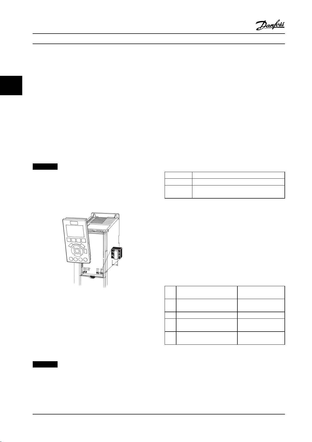
3.4.22 Switches S201, S202, and S801
Use switches S201 (A53) and S202 (A54) to select a current
(0–20 mA) or a voltage (-10 V to 10 V) configuration of the
33
analog input terminals 53 and 54 respectively.
Switch S801 (BUS TER.) can be used to enable termination
on the RS-485 port (terminals 68 and 69).
See Figure 3.26.
Default setting:
S201 (A53) = OFF (voltage input)
S202 (A54) = OFF (voltage input)
S801 (Bus termination) = OFF
Terminate each segment at both ends using either the
termination switch (S801) of the adjustable frequency
drives or a biased termination resistor network. Always use
shielded twisted pair (STP) cable for bus cabling, and
always follow good common installation practice.
Low-impedance ground connection of the shield at every
node is important, including at high frequencies. Thus,
connect a large surface of the shield to ground, for
example, with a cable clamp or a conductive cable
connector. It may be necessary to apply potentialequalizing cables to maintain the same ground potential
throughout the network - particularly in installations with
long cables.
To prevent impedance mismatch, always use the same
type of cable throughout the entire network. When
connecting a motor to the adjustable frequency drives,
always use shielded motor cable.
NOTICE!
When changing the function of S201, S202 or S801 do
not use force for the switch over. Remove the LCP cradle
when operating the switches. The switches must not be
operated while the adjustable frequency drive is
powered.
Cable Shielded twisted pair (STP)
Impedance
Cable length
Table 3.13 Cable Recommendations
120 Ω
Max. 4000 ft [1200 m] (including drop lines)
Max. 1,650 ft [500 m] station-to-station
Figure 3.30 Remove the LCP Cradle to Access Switches
3.4.23
RS-485 is a 2-wire bus interface compatible with multi-drop
network topology, i.e., nodes can be connected as a bus,
or via drop cables from a common trunk line. A total of 32
nodes can be connected to one network segment.
Repeaters divide network
Serial Communication
NOTICE!
Each repeater functions as a node within the segment in
which it is installed. Each node connected within a given
network must have a unique node address across all
segments.
3.5
Final Set-up and Test
Before operating the adjustable frequency drive, perform a
final test of the installation:
1. Locate the motor nameplate to find out whether
the motor is star (Y) or delta connected (Δ).
2. Enter the motor nameplate data in the parameter
list. Access the list by pressing the [Quick Menu]
key and selecting Q2 Quick Set-up. See Table 3.14.
Motor Power [kW]
1.
or Motor Power [HP]
2. Motor Voltage parameter 1-22 Motor
3. Motor Frequency 1-23 Motor Frequency
4. Motor Current parameter 1-24 Motor
5. Motor Nominal Speed parameter 1-25 Motor
Table 3.14 Quick Set-up Parameters
1-20 Motor Power [kW]
1-21 Motor Power [HP]
Voltage
Current
Nominal Speed
36 Danfoss A/S © Rev. 2014-02-07 All rights reserved. MG37A222
Page 39

3~ MOTOR NR. 1827421 2003
S/E005A9
1,5 KW
n 31,5 /MIN. 400 Y V
n 1400 /MIN. 50 Hz
cos 0,80 3,6 A
1,7L
B IP 65 H1/1A
130BT307.10
BAUER D-7 3734 ESLINGEN
Installation
Instruction Manual
Stop the AMA during operation
Successful AMA
Figure 3.31 Motor Nameplate
The display shows “Press [OK] to finish AMA”.
•
Press [OK] to exit the AMA state.
•
Unsuccessful AMA
The adjustable frequency drive enters into alarm
•
mode. A description of the alarm can be found in
chapter 9 Warnings and Alarms.
"Report Value” in the alarm log shows the last
•
measuring sequence carried out by the AMA,
before the adjustable frequency drive entered
alarm mode. This number, along with the
description of the alarm, will assist in troubleshooting. Mention the number and alarm
description when contacting Danfoss service
personnel.
Unsuccessful AMA is often caused by incorrectly registered
motor nameplate data or too big a difference between the
motor power size and the adjustable frequency drive
power size.
Set up the desired limits for speed and ramp time.
Minimum Reference
Maximum Reference 3-03 Maximum Reference
Table 3.15 Reference Parameters
3-02 Minimum Reference
3 3
3. Perform an Automatic Motor Adaptation (AMA) to
ensure optimum performance.
a. Connect terminal 27 to terminal 12 or set
5-12 Terminal 27 Digital Input to 'No function'
(5-12 Terminal 27 Digital Input [0]).
b.
Activate the AMA 1-29 Automatic Motor
Adaptation (AMA).
c. Select complete or reduced AMA. If an LC filter is
mounted, run only the reduced AMA, or remove
Motor Speed Low Limit
Motor Speed High Limit 4-13 Motor Speed High Limit
Table 3.16 Speed Limits
Ramp-up Time 1 [s]
Ramp-down Time 1 [s] 3-42 Ramp 1 Ramp-down Time
4-11 Motor Speed Low Limit
[RPM] or 4-12 Motor Speed
Low Limit [Hz]
[RPM] or 4-14 Motor Speed
High Limit [Hz]
3-41 Ramp 1 Ramp-up Time
the LC filter during the AMA procedure.
d. Press [OK]. The display shows “Press [Hand On] to
Table 3.17 Ramp Times
start.”
e. Press [Hand On]. A progress bar indicates if the
AMA is in progress.
f. Press [Off] - the adjustable frequency drive enters
into alarm mode and the display shows that the
AMA was terminated by the user.
MG37A222 Danfoss A/S © Rev. 2014-02-07 All rights reserved. 37
Page 40

LC lter
130BA170.10
Installation
Instruction Manual
3.6 Additional Connections
3.6.1 Mechanical Brake Control
33
In hoisting/lowering applications, it is necessary to be
able to control an electro-mechanical brake:
Control the brake using any relay output or
•
digital output (terminal 27 or 29).
Keep the output closed (voltage-free) as long as
•
the adjustable frequency drive is unable to
‘support’ the motor, e.g., due to the load being
too heavy.
Select [32] Mechanical brake control in parameter
•
group 5-4* Relays for applications with an electromechanical brake.
The brake is released when the motor current
•
exceeds the preset value in
parameter 2-20 Release Brake Current.
The brake engages when the output frequency is
•
less than the frequency set in
parameter 2-21 Activate Brake Speed [RPM] or
parameter 2-22 Activate Brake Speed [Hz], only if
the adjustable frequency drive completes a stop
command.
If the adjustable frequency drive is in alarm mode or in an
overvoltage situation, the mechanical brake immediately
cuts in.
NOTICE!
The electronic thermal relay (ETR) of the adjustable
frequency drive cannot be used as motor protection for
the individual motor of systems with motors connected
in parallel. Provide further motor protection with
thermistors in each motor or individual thermal relays.
Circuit breakers are not suitable as protection.
Parallel Connection of Motors
3.6.2
The adjustable frequency drive can control several motors
connected in parallel. The total current consumption of the
motors must not exceed the rated output current I
the adjustable frequency drive.
NOTICE!
Installations with cables connected in a common joint as
in Figure 3.32, is only recommended for short cable
lengths.
NOTICE!
When motors are connected in parallel, 1-29 Automatic
Motor Adaptation (AMA) cannot be used.
M,N
for
Figure 3.32 Installations with Cables Connected in a
Common Joint
Problems are possible at start and at low RPM values if
motor sizes vary widely. The relatively high ohmic
resistance in the stator of small motors calls for a higher
voltage at start and at low RPM values.
38 Danfoss A/S © Rev. 2014-02-07 All rights reserved. MG37A222
Page 41

Installation Instruction Manual
3.6.3 Motor Thermal Protection
The electronic thermal relay in the adjustable frequency
drive has received UL-approval for single motor protection,
when parameter 1-90 Motor Thermal Protection is set for
ETR Trip and 1-24 Motor Current is set to the rated motor
current (see motor nameplate).
For thermal motor protection, it is also possible to use the
MCB 112 PTC thermistor card option. This card provides
ATEX certification to protect motors in explosion hazardous
areas, Zone 1/21 and Zone 2/22. When
parameter 1-90 Motor Thermal Protection is set to [20] ATEX
ETR and MCB 112 are combined. It is possible to control an
Ex-e motor in explosion hazardous areas. Consult the
programming guide for details on how to set up the
adjustable frequency drive for safe operation of Ex-e
motors.
3 3
MG37A222 Danfoss A/S © Rev. 2014-02-07 All rights reserved. 39
Page 42

Start-up and Functional Tes...
Instruction Manual
4 Start-up and Functional Testing
4.1 Pre-start
CAUTION
44
Before applying power to the unit, inspect the entire installation as detailed in Table 4.1. Check mark those items when
completed.
Inspect for Description
Auxiliary equipment
Cable routing
Look for auxiliary equipment, switches, disconnects, or input fuses/circuit breakers on the input
•
power side of the adjustable frequency drive or output side to the motor. Ensure that they are ready
for full speed operation.
Check function and installation of any sensors used for feedback to the adjustable frequency drive.
•
Remove power factor correction caps on motors, if present.
•
Use separate metallic conduits for each of the following:
•
•
•
•
Control wiring
Cooling clearance
EMC considerations
Environmental considerations
Fusing and circuit
breakers
Grounding
Input and output power
wiring
Panel interior
Switches
Vibration
Check for broken or damaged wires and loose connections.
•
Check that control wiring is isolated from power and motor wiring for noise immunity.
•
Check the voltage source of the signals, if necessary.
•
The use of shielded cable or twisted pair is recommended. Ensure that the shield is terminated
•
correctly.
Make sure that the top and bottom clearance is adequate to ensure proper airflow for cooling.
•
Check for proper installation regarding electromagnetic compatibility.
•
See equipment label for the maximum ambient operating temperature limits.
•
Humidity levels must be 5–95% non-condensing.
•
Check for proper fusing or circuit breakers.
•
Check that all fuses are inserted firmly and in operational condition and that all circuit breakers are
•
in the open position.
The unit requires a ground wire from its chassis to the building ground.
•
Check for good ground connections that are tight and free of oxidation.
•
Grounding to conduit or mounting the back panel to a metal surface is not a suitable ground.
•
Check for loose connections.
•
Check that motor and line power are in separate conduits or separated shielded cables.
•
Make sure that the unit interior is free of debris and corrosion.
•
Ensure that all switch and disconnect settings are in the proper positions.
•
Check that the unit is mounted solidly or that shock mounts are used, as necessary.
•
Check for an unusual amount of vibration.
•
☑
input power
motor wiring
control wiring
Table 4.1 Start-up Checklist
40 Danfoss A/S © Rev. 2014-02-07 All rights reserved. MG37A222
Page 43

130BP066.10
1107 RPM
0 - ** Operation/Display
1 - ** Load/Motor
2 - ** Brakes
3 - ** Reference / Ramps
3.84 A 1 (1)
Main Menu
Start-up and Functional Tes... Instruction Manual
4.2 Applying Power to the Equipment
WARNING
HIGH VOLTAGE!
Adjustable frequency drives contain high voltage when
connected to AC line power. Installation, start-up and
maintenance should be performed by qualified
personnel only. Failure to comply could result in death
or serious injury.
WARNING
UNINTENDED START!
When the adjustable frequency drive is connected to AC
line power, the motor may start at any time. The
adjustable frequency drive, motor, and any driven
equipment must be in operational readiness. Failure to
comply could result in death, serious injury, equipment,
or property damage.
1. Confirm that the input voltage is balanced within
3%. If not, correct input voltage imbalance before
proceeding.
2. Ensure that optional equipment wiring (if
present) matches the installation application.
3. Ensure that all operator devices are off. Panel
doors should be closed or cover mounted.
4. Apply power to the unit. Do not start the
adjustable frequency drive at this time. For units
with a disconnect switch, turn the switch on to
apply power.
NOTICE!
If the status line at the bottom of the LCP reads AUTO
REMOTE COASTING or Alarm 60 External Interlock is
displayed, this indicates that the unit is ready to operate
but is missing an input signal on terminal 27.
4.3 Basic Operational Programming
Adjustable frequency drives require basic operational
programming before running for best performance. Basic
operational programming requires entering motor
nameplate data for the motor being operated and the
minimum and maximum motor speeds. The recommended
parameter settings are intended for start-up and checkout
purposes. Application settings may vary. See
chapter 5.1 How to Operate for detailed instructions on
entering data through the LCP.
Enter data with power ON, but before operating the
adjustable frequency drive. There are two ways of
programming the adjustable frequency drive: either by
using the Smart Application Set-up (SAS) or by using the
procedure described further down. The SAS is a quick
wizard for setting up the most commonly used
applications. At the first power-up and after a reset the
SAS appears on the LCP. Follow the instructions that
appear on the successive screens for setting up the
applications listed. SAS can also be found under the Quick
Menu. [Info] is used throughout the Smart Set-up to see
help information for various selections, settings and
messages.
NOTICE!
The start conditions are ignored while in the wizard.
NOTICE!
If no action is taken after first power-up or reset, the SAS
screen will automatically disappear after 10 minutes.
When not using the SAS, enter data in accordance with
the following procedure.
1. Press [Main Menu] twice on the LCP.
2. Press the navigation keys to scroll to parameter
group 0-** Operation/Display.
3. Press [OK].
4 4
Figure 4.1 0-** Operation/Display
MG37A222 Danfoss A/S © Rev. 2014-02-07 All rights reserved. 41
Page 44

0-
**
Operation / Display
0.0%
0-0
*
Basic Settings
0-1
*
Set-up Operations
0-2
*
LCP Display
0-3
*
LCP Custom Readout
0.00A 1(1)
130BP087.10
0-0
*
Basic Settings
0.0%
0-03 Regional Settings
[0] International
0.00A 1(1)
130BP088.10
130BB847.10
Q1 My Personal Menu
Q2 Quick Setup
Q5 Changes Made
Q6 Loggings
13.7% 13.0A 1(1)
Quick Menus
130BT772.10
Q2
0.0 Hz 0.00kW 1(1)
Motor Setup
1 - 21 Motor Power [kW]
4.0 kW
Start-up and Functional Tes... Instruction Manual
4. Press the navigation keys to scroll to parameter
10. Select language and press [OK].
group 0-0* Basic Settings and press [OK].
44
Figure 4.5 Select Language
Figure 4.2 0-0* Basic Settings
11. If a jumper wire is placed between control
5. Press the navigation keys to scroll to
0-03 Regional Settings and press [OK].
Figure 4.3 0-03 Regional Settings
terminals 12 and 27 leave 5-12 Terminal 27 Digital
Input at factory default. Otherwise select No
Operation. For adjustable frequency drives with
an optional bypass, no jumper wire is required.
12.
parameter 3-02 Minimum Reference
13.
parameter 3-03 Maximum Reference
14.
3-41 Ramp 1 Ramp-up Time
15.
3-42 Ramp 1 Ramp-down Time
16.
3-13 Reference Site. Linked to Hand/Auto* Local
Remote.
6.
Press the navigation keys to select International
or North America as appropriate and press [OK].
(This changes the default settings for a number
of basic parameters. See chapter 6 Programming
for a complete list.)
7. Press [Quick Menu] on the LCP.
8. Press the navigation keys to scroll to parameter
group Q2 Quick Set-up.
9. Press [OK].
Figure 4.4 Q2 Quick Set-up
4.4
Local Control Test
CAUTION
MOTOR START!
Ensure that the motor, system and any attached
equipment are ready for start. It is the responsibility of
the user to ensure safe operation under any condition.
Failure to ensure that the motor, system, and any
attached equipment are ready for start could result in
personal injury or equipment damage.
NOTICE!
The [Hand On] key provides a local start command to
the adjustable frequency drive. The [Off] key provides
the stop function.
When operating in local mode, [▲] and [▼] increase and
decrease the speed output of the adjustable frequency
drive. [◄] and [►] move the display cursor in the numeric
display.
42 Danfoss A/S © Rev. 2014-02-07 All rights reserved. MG37A222
Page 45

Start-up and Functional Tes... Instruction Manual
1. Press [Hand On].
2. Accelerate the adjustable frequency drive by
pressing [▲] to full speed. Moving the cursor left
of the decimal point provides quicker input
changes.
3. Note any acceleration problems.
4. Press [Off].
5. Note any deceleration problems.
If acceleration problems were encountered
If warnings or alarms occur, see
•
chapter 9 Warnings and Alarms
Check that motor data is entered correctly.
•
Increase the ramp-up time in 3-41 Ramp 1 Ramp-
•
up Time.
Increase current limit in 4-18 Current Limit.
•
Increase torque limit in 4-16 Torque Limit Motor
•
Mode.
If deceleration problems were encountered
If warnings or alarms occur, see
•
chapter 9 Warnings and Alarms.
Check that motor data is entered correctly.
•
Increase the ramp-down time in 3-42 Ramp 1
•
Ramp-down Time.
Enable overvoltage control in 2-17 Over-voltage
•
Control.
See chapter 5.1.2 How to Operate the Graphical LCP (GLCP)
for resetting the adjustable frequency drive after a trip.
4.5 System Start-up
Complete user wiring and application programming before
performing the procedure in this section. See
chapter 7 Application Examples for application set-up
information. The following procedure is recommended
after application set-up by the user is completed.
4 4
CAUTION
MOTOR START!
Ensure that the motor, system, and any attached
equipment are ready for start. It is the responsibility of
the user to ensure safe operation under any condition.
Failure to ensure that the motor, system, and any
attached equipment are ready for start could result in
personal injury or equipment damage.
1. Press [Auto On].
2. Ensure that external control functions are
properly wired to the adjustable frequency drive
and all programming is completed.
3. Apply an external run command.
4. Adjust the speed reference throughout the speed
range.
5. Remove the external run command.
6. Note any problem.
If warnings or alarms occur, see chapter 9 Warnings and
Alarms.
NOTICE!
chapter 4.1 Pre-start to chapter 4.3 Basic Operational
Programming conclude the procedures for applying
power to the adjustable frequency drive, basic
programming, set-up and functional testing.
MG37A222 Danfoss A/S © Rev. 2014-02-07 All rights reserved. 43
Page 46

Auto
on
Reset
Hand
on
O
Status
Quick
Menu
Main
Menu
Alarm
Log
Back
Cancel
Info
OK
Status
1(0)
1234rpm 10,4A 43,5Hz
Run OK
43,5Hz
On
Alarm
Warn.
130BA018.13
1
2
3
4
b
a
c
User Interface Instruction Manual
5 User Interface
5.1 How to Operate
5.1.1 Modes of Operation
The Low Harmonic Drive can be operated in two ways:
Graphical Local Control Panel (GLCP)
•
RS-485 serial communication or USB, both for PC
55
•
1. Display
1a
1b
Status line: Status messages displaying
icons and graphics.
Line 1–2: Operator data lines displaying
data and variables the user defines. By
pressing the [Status] key, up to one
extra line can be added.
connection
1c
Status line: Status messages displaying
5.1.2 How to Operate the Graphical LCP
(GLCP)
2. Menu soft keys
text.
3. Indicator lights/navigation panel
The Low Harmonic Drive has 2 LCPs, one each on the
adjustable frequency drive section (right) and active filter
4. Operational keys
section (left). Both LCPs function in the same way. Each
LCP controls only the unit it is connected to and there is
no communication between the two LCPs. How to operate
the Graphical LCP (GLCP)
NOTICE!
The active filter should be in auto mode. Press [Auto On]
on the filter LCP.
The following instructions are valid for the GLCP (LCP 102).
The GLCP is divided into four functional groups:
Graphical display with status lines.
•
Menu keys and indicator lights (LEDs) - selecting
•
mode, changing parameters and switching
between display functions.
Navigation keys and indicator lights (LEDs).
•
Operation keys and LEDs.
•
Graphical display:
The LCD display is back-lit with a total of six alpha-numeric
lines. All data is displayed on the LCP, which can show up
to five operating variables while in [Status] mode.
Figure 5.1 shows an example of the adjustable frequency
drive LCP. The filter LCP looks identical but displays
information related to the filter operation.
Figure 5.1 LCP
44 Danfoss A/S © Rev. 2014-02-07 All rights reserved. MG37A222
Page 47
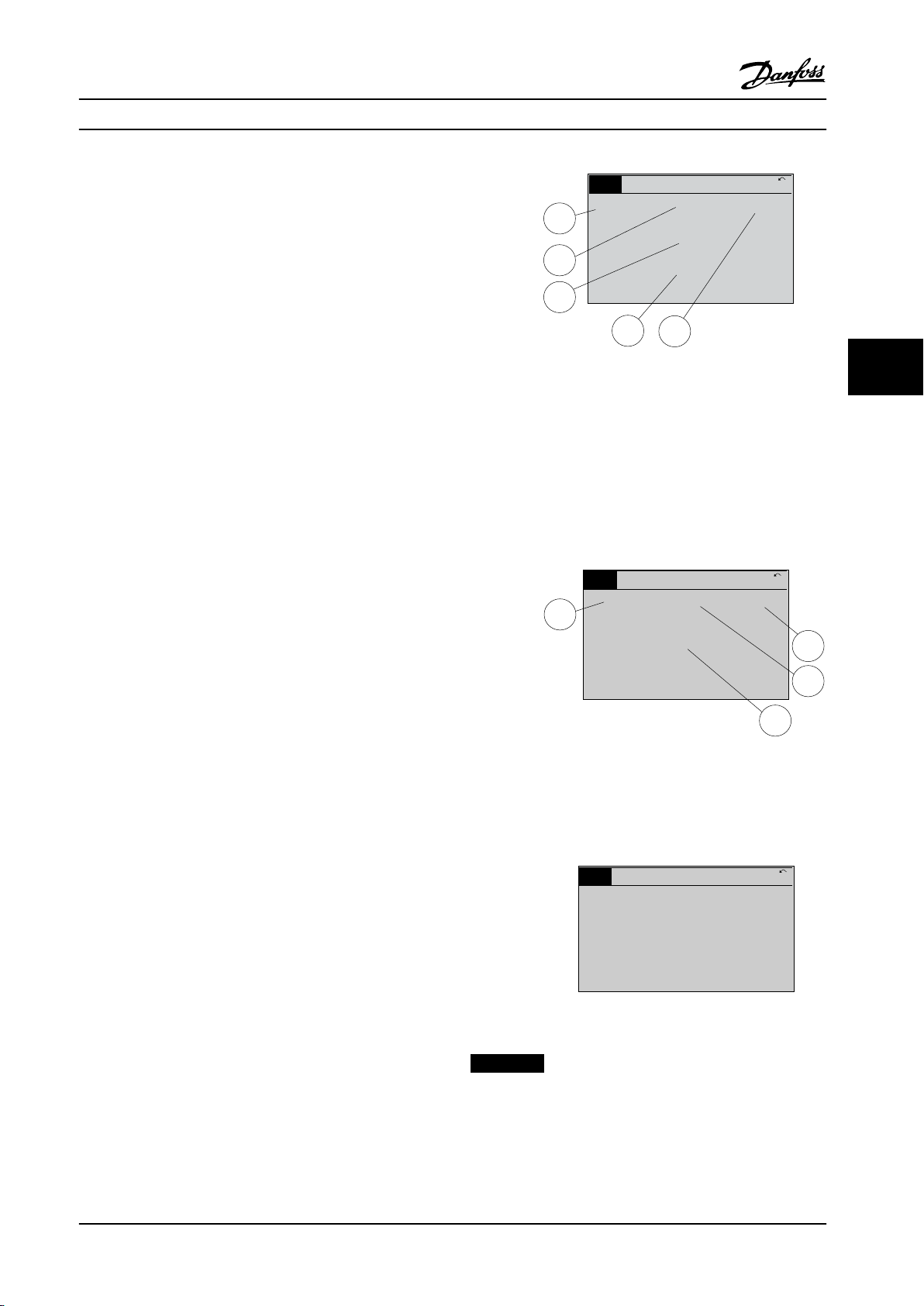
1.1
2
3
1.3
1.2
130BP041.10
799 RPM
Auto Remote Ramping
1 (1)
36.4 kW7.83 A
0.000
53.2%
Status
1.1
1.2
2
1.3
130BP062.10
207RPM
Auto Remote Running
1 (1)
24.4 kW5.25A
6.9Hz
Status
130BP063.10
778 RPM
Auto Remote Running
1 (1)
4.0 kW0.86 A
State: 0 o 0 (o)
When: Do: -
Status
User Interface Instruction Manual
The display is divided into three sections:
Top section (a)
Shows the status when in status mode or up to two
variables when not in status mode and in the case of
alarm/warning.
The number of the active set-up (selected as the active
set-up in 0-10 Active Set-up) is shown. When programming
in another set-up than the active set-up, the number of
the set-up being programmed appears to the right in
brackets.
Figure 5.2 Status Display I - Operating Variables
5 5
Middle section (b)
Shows up to five variables with related unit, regardless of
status. In the event of an alarm/warning, the warning is
shown instead of the variables.
It is possible to toggle between three status readout
displays by pressing [Status].
Operating variables with different formatting are shown in
each status screen.
Several values or measurements can be linked to each of
the displayed operating variables. The values/
measurements to be displayed can be defined via
parameters 0–20, 0–21, 0–22, 0–23, and 0–24.
Each value/measurement readout parameter selected in
parameters 0–20 to 0–24 has its own scale and number of
digits after a possible decimal point. Larger numeric values
are displayed with few digits after the decimal point.
Ex.: Current readout
5.25 A; 15.2 A 105 A.
Status display I
This readout state is standard after startup or initialization.
Press [Info] to obtain information about the value/
measurement linked to the displayed operating variables
(1.1, 1.2, 1.3, 2, and 3).
See the operating variables shown in the display in
Figure 5.2. 1.1, 1.2 and 1.3 are shown in small size. 2 and 3
are shown in medium size.
Status display II
See the operating variables (1.1, 1.2, 1.3, and 2) shown in
the display in Figure 5.3.
In the example, speed, motor current, motor power, and
frequency are selected as variables in the first and second
lines.
1.1, 1.2 and 1.3 are shown in small size. 2 is shown in large
size.
Figure 5.3 Status Display II - Operating Variables
Status display III
This state displays the event and action of the smart logic
control.
Figure 5.4 Status Display III - Operating Variables
NOTICE!
Status display III is not available on the filter LCP.
MG37A222 Danfoss A/S © Rev. 2014-02-07 All rights reserved. 45
Page 48

Top section
Middle section
Bottom section
Status
43 RPM
1.4 Hz
Auto Remote Running
! Pwr.card temp (W29)
2.9%
5.44 A 25.3 kW
1(1)
130BP074.10
!
On
Warn.
Alarm
130BP044.10
130BP045.10
Status
Quick
Menu
Main
Menu
Alarm
Log
User Interface
Instruction Manual
Bottom section
always shows the state of the adjustable frequency drive in
status mode.
[Status]
Indicates the status of the adjustable frequency drive
(and/or the motor) or the filter respectively. On the drive
LCP, three different readouts can be selected by pressing
the [Status] key:
Five line readouts, four line readouts, or Smart Logic
Control.
Smart Logic Control is not available for the filter.
Use [Status] for selecting display mode or reverting to
display mode from:
55
Figure 5.5 Bottom Section Status Mode
Display contrast adjustment
Press [status] and [▲] for darker display
Press [Status] and [▼] for brighter display
LEDs:
If certain threshold values are exceeded, the alarm and/or
warning LED lights up. A status and alarm text appear on
the control panel.
The On LED is activated when the adjustable frequency
Use the [Status] key to toggle single or double readout
mode. Status
[Quick Menu]
Allows quick set-up of the adjustable frequency drive or
the filter and programming of the most common
functions. Quick menu
The [Quick Menu] consists of:
drive receives power from:
AC line voltage
•
a DC bus terminal
•
an external 24 V supply
•
At the same time, the back light is on. LEDs
Green LED/On: Control section is working.
•
Yellow LED/Warn: Indicates a warning.
•
Flashing Red LED/Alarm: Indicates an alarm.
•
Since the active filter is an integrated part of the Low
Harmonic Drive, only a minimum of programming is
necessary. The filter LCP displays information about filter
operation such as THD of voltage or current, corrected
current, injected current or Cos ϕ and true power factor.
quick menu
•
main menu
•
alarm mode
•
Q1: My Personal Menu
•
Q2: Quick Set-up
•
Q5: Changes Made
•
Q6: Loggings
•
The Quick Menu parameters can be accessed immediately
unless a password has been created via parameters 0–60,
0–61, 0–65 or 0–66.
It is possible to switch directly between quick menu mode
and main menu mode.
Figure 5.6 LED Status Lights
[Main Menu]
Is used for programming all parameters.
GLCP keys
Menu keys
The menu keys are divided into functions. The keys below
the display and LEDs are used for parameter set-up,
including choice of display indication during normal
operation.
The main menu parameters can be accessed immediately
unless a password has been created via parameters 0–60,
0–61, 0–65 or 0–66.
It is possible to switch directly between main menu mode
and quick menu mode.
Parameter shortcut can be carried out by pressing down
the [Main Menu] key for three seconds. The parameter
shortcut allows direct access to any parameter.
Figure 5.7 Menu Keys
46 Danfoss A/S © Rev. 2014-02-07 All rights reserved. MG37A222
Page 49

B
a
c
k
C
a
n
c
e
l
I
n
f
o
130BT117.10
OK
Back
Info
Warn
Alarm
On
Cancel
130BP046.10
Hand
on
O
Auto
on
Reset
User Interface Instruction Manual
[Alarm Log]
Displays an alarm list of the five latest alarms (numbered
A1-A5). To obtain more details about an alarm, use the
arrow keys to navigate to the alarm number and press
[OK]. Information is displayed about the condition of the
adjustable frequency drive or filter before it enters alarm
mode.
[Back]
Reverts to the previous step or layer in the navigation
structure.
Figure 5.8 Back Key
[Cancel]
Last change or command is cancelled as long as the
display has not been changed.
Figure 5.9 Cancel Key
[OK]
Is used for selecting a parameter marked by the cursor and
for enabling the change of a parameter.
5 5
Figure 5.11 Navigation Keys
Operation keys
For local control. Found at the bottom of the control
panel.
[Info]
Displays information about a command, parameter, or
function in any display window. [Info] provides detailed
information when needed.
Exit Info mode by pressing either [Info], [Back], or [Cancel].
Figure 5.10 Info Key
Navigation keys
The four navigation keys are used to navigate between the
choices available in [Quick Menu], [Main Menu] and
[Alarm Log]. Move the cursor with the navigation keys.
Figure 5.12 Operation Keys
[Hand On]
Enables control of the adjustable frequency drive via the
GLCP. [Hand On] also starts the motor, and it is now
possible to give the motor speed reference with the arrow
keys. The key can be [1] Enabled or [0] Disabled via
0-40 [Hand on] Key on LCP.
The following control signals are active when [Hand On]
is activated:
[Hand On] - [Off] - [Auto On]
•
Reset
•
Coasting stop inverse (motor coasting to stop)
•
Reversing
•
Set-up select lsb - Set-up select msb
•
Stop command from serial communication
•
Quick stop
•
DC brake
•
NOTICE!
External stop signals activated with control signals or a
serial bus overrides a Start command via the LCP.
MG37A222 Danfoss A/S © Rev. 2014-02-07 All rights reserved. 47
Page 50

130BP068.10
740RPM
0 -01 Language
[0] English
10.64 A 1 [1]
0-0*
Basic Settings
130BP069.10
1- 6*
113 RPM 1.78 A 1(1)
Load depen. setting
1 - 60 Low speed load
compensation
1
0
0%
130BP070.10
1 - 60 Low speed load
compensation
1 0%
Load depen. setting 1- 6*
729RPM 6.21A 1(1)
6
User Interface Instruction Manual
[Off]
5.1.4
Changing a Text Value
Stops the connected motor (when pressed on the
adjustable frequency drive LCP) or the filter (when pressed
on the filter LCP). The key can be [1] Enabled or [0]
Disabled via 0-41 [Off] Key on LCP. If no external stop
function is selected and the [Off] key is inactive, the motor
can only be stopped by disconnecting the line power
If the selected parameter is a text value, change the text
value by using the [▲]/[▼] keys.
[▲] increases the value, and [▼] decreases the value. Place
the cursor on the value to be saved and press [OK].
supply.
[Auto On]
Enables the adjustable frequency drive to be controlled via
55
the control terminals and/or serial communication. When a
start signal is applied on the control terminals and/or the
bus, the adjustable frequency drive starts. The key can be
[1] Enabled or [0] Disabled via 0-42 [Auto on] Key on LCP.
NOTICE!
Figure 5.13 Display Example
An active HAND-OFF-AUTO signal via the digital inputs
has higher priority than the control keys [Hand On] –
[Auto On].
5.1.5 Changing a Group of Numeric Data
Values
[Reset]
Is used for resetting the adjustable frequency drive or filter
after an alarm (trip). The key can be [1] Enabled or [0]
Disabled via 0-43 [Reset] Key on LCP on the LCP. Reset
The parameter shortcut
Can be carried out by holding down the [Main Menu] key
for 3 seconds. The parameter shortcut allows direct access
to any parameter.
If the selected parameter represents a numeric data value,
change the selected data value pressing the [◄] and [►]
navigation keys as well as [▲] and [▼] keys. Press [◄] and
[►] to move the cursor horizontally.
Changing Data
5.1.3
1. Press [Quick Menu] or [Main Menu].
2.
Use [▲] and [▼] to find parameter group to edit.
Changing data
Figure 5.14 Display Example
3. Press [OK].
4.
Use [▲] and [▼] to find parameter to edit.
5. Press [OK].
6.
Use [▲] and [▼] to select correct parameter
Press [
]/[▼] to change the data value. [▲] enlarges the
▲
data value, and [▼] reduces the data value. Place the
cursor on the value to be saved and press [OK].
setting. Or, to move to digits within a number,
use [◄] and [►]. The cursor indicates the digit
selected to be changed. The [▲] key increases the
value, the [▼] key decreases the value.
7. Press [Cancel] to ignore the change, or press [OK]
to accept the change and enter a new setting.
Figure 5.15 Display Example
48 Danfoss A/S © Rev. 2014-02-07 All rights reserved. MG37A222
Page 51

User Interface Instruction Manual
5.1.6 Changing Data Values, Step-by-Step
Certain parameters can be changed step-by-step or
infinitely variably. This method applies to 1-20 Motor Power
[kW], parameter 1-22 Motor Voltage, and 1-23 Motor
Frequency.
The parameters are changed both as a group of numeric
data values, and as numeric data values using an infinite
number of variables.
5.1.7 Readout and Programming of
Indexed Parameters
Parameters are indexed when placed in a rolling stack.
15-30 Alarm Log: Error Code to 15-32 Alarm Log: Time
contain a fault log which can be read out. Select a
parameter, press [OK], and use the up/down navigation
keys to scroll through the value log.
Use 3-10 Preset Reference as another example:
Select the parameter, press [OK], and press [▲]/[▼] to scroll
through the indexed values. To change the parameter
value, select the indexed value and press [OK]. Change the
value by using [▲]/[▼]. Press [OK] to accept the new
setting. Press [Cancel] to abort. Press [Back] to leave the
parameter.
Quick Transfer of Parameter Settings
5.1.8
when Using GLCP
Once the set-up is complete, store (back up) the parameter
settings in the GLCP or on a PC via MCT 10 Set-up
software tool.
WARNING
Stop the motor before performing any of these
operations.
Data storage in LCP
1.
Go to 0-50 LCP Copy
2. Press [OK]
3.
Select [1] All to LCP
4. Press [OK]
All the parameter settings are now stored in the GLCP as
indicated by the progress bar. When 100% is reached,
press [OK].
Data transfer from LCP to adjustable frequency drive
1.
Go to 0-50 LCP Copy
2. Press [OK]
3.
Select [2] All from LCP
4. Press [OK]
The parameter settings stored in the GLCP are now
transferred to the adjustable frequency drive, as indicated
by the progress bar. When 100% is reached, press [OK].
5.1.9 Initialization to Default Settings
There are two ways to initialize the adjustable frequency
drive to default: Recommended initialization and manual
initialization.
Each method has a different impact. InitializationDefault
settings
5.1.9.1
Initialization via 14-22 Operation Mode)
14-22 Operation Mode initializes all except:
Parameter 14-50 RFI 1
8-30 Protocol
8-31 Address
8-32 Baud Rate
8-35 Minimum Response Delay
8-36 Max Response Delay
8-37 Maximum Inter-Char Delay
15-00 Operating hours to 15-05 Over Volts
15-20 Historic Log: Event to 15-22 Historic Log: Time
15-30 Alarm Log: Error Code to 15-32 Alarm Log: Time
Recommended Initialization Method
1.
Select 14-22 Operation Mode
2. Press [OK]
3.
Select Initialization (for NLCP select “2”)
4. Press [OK]
5. Remove power to the unit and wait for the
display to turn off.
6. Reconnect power to reset the adjustable
frequency drive.
7. Press [Reset]
NOTICE!
Parameters selected in 0-25 My Personal Menu, stays
present, with default factory setting.
5 5
The GLCP can now be connected to another adjustable
frequency drive, and the parameter settings can be copied
to this adjustable frequency drive.
MG37A222 Danfoss A/S © Rev. 2014-02-07 All rights reserved. 49
Page 52

130BA060.11
68 69 68 69 68 69
RS 485
RS 232
USB
+
-
130BT308.10
User Interface Instruction Manual
5.1.9.2 Manual Initialization Method
Bus termination
Terminate the RS-485 bus by a resistor network at both
NOTICE!
When carrying out manual initialization, serial communication, RFI filter settings and fault log settings are reset.
Removes parameters selected in 0-25 My Personal Menu.
1. Disconnect from the line power and wait until
the display turns off.
55
2a. Press [Status] - [Main Menu] - [OK] at the
same time while power-up for graphical LCP
(GLCP)
2b. Press [Menu] while power-up for LCP 101,
numerical display
3. Release the keys after 5 s
4. The adjustable frequency drive is now
ends. If the adjustable frequency drive is the first or the
last device in the RS-485 loop, set the switch S801 on the
control card for ON.
For more information, see chapter 3.4.22 Switches S201,
S202, and S801.
5.1.11 How to Connect a PC to the
Adjustable Frequency Drive
To control or program the Low Harmonic Drive from a PC,
install the PC-based configuration tool MCT 10 Set-up
Software.
The PC is connected via a standard (host/device) USB cable
to both adjustable frequency drive and filter, or via the
RS-485 interface. How to connect a PC to the adjustable
frequency drive
programmed according to default settings
This parameter initializes all except:
15-00 Operating hours
15-03 Power-ups
15-04 Over Temps
15-05 Over Volts
NOTICE!
The USB connection is galvanically isolated from the
supply voltage (PELV) and other high-voltage terminals.
The USB connection is connected to ground protection
on the adjustable frequency drive. Use only an isolated
laptop as PC connection to the USB connector on the
5.1.10
RS-485 Bus Connection
adjustable frequency drive.
Both filter and adjustable frequency drive can be
connected to a controller (or master) together with other
loads using the RS-485 standard interface. Terminal 68 is
connected to the P signal (TX+, RX+), while terminal 69 is
connected to the N signal (TX-, RX-).
Always use parallel connections for the Low Harmonic
Drive to ensure that both filter and drive are connected.
Figure 5.16 Connection Example
To avoid potential equalizing currents in the shield, ground
the cable shield via terminal 61, which is connected to the
frame via an RC link.
For control cable connections, see chapter 3.4.20 Electrical
Installation, Control Cables.
Figure 5.17 Control Cable Connections
50 Danfoss A/S © Rev. 2014-02-07 All rights reserved. MG37A222
Page 53

User Interface Instruction Manual
5.1.12 PC Software Tools
PC-based Configuration Tool MCT 10 Set-up Software
The Low Harmonic Drive is equipped with two serial
communication ports. Danfoss provides a PC tool for
communication between PC and adjustable frequency
drive, MCT 10 Set-up Software. Check chapter 2.4 Additional
Resources for detailed information on this tool.
MCT 10 set-up software
MCT 10 is an interactive tool for setting parameters in
Danfoss adjustable frequency drives.
The MCT 10 set-up software is useful for:
Planning a communication network offline. MCT
•
10 contains a complete adjustable frequency
drive database
Commissioning adjustable frequency drives online
•
Saving settings for all adjustable frequency drives.
•
Replacing an adjustable frequency drive in a
•
network.
Simple and accurate documentation of adjustable
•
frequency drive settings after commissioning.
Expanding an existing network
•
Future developed adjustable frequency drives are
•
supported
Load adjustable frequency drive settings
1. Connect a PC to the adjustable frequency drive
via the USB com port
2. Open MCT 10 Set-up software
3. Select “Open” to show stored files
4. Open the appropriate file
5. Select “Write to drive”
All parameter settings are now transferred to the
adjustable frequency drive.
5 5
MCT 10 set-up software supports Profibus DP-V1 via a
Master class 2 connection. It enables online read/write
parameters in an adjustable frequency drive via the
Profibus network, eliminating the need for an extra
communication network.
Save adjustable frequency drive settings
1. Connect a PC to the unit via the USB COM port.
CAUTION
Use a PC, which is isolated from the line power, with the
USB port. Failure to do so can damage equipment.
2. Open MCT 10 Set-up Software
3. Select “Read from drive”
4. Select “Save as”
All parameters are now stored on the PC.
MG37A222 Danfoss A/S © Rev. 2014-02-07 All rights reserved. 51
Page 54

Programming Instruction Manual
6 Programming
6.1 How to Program the Adjustable
Frequency Drive
0-01 Language
Option: Function:
Polski Part of Language package 4
6.1.1 Quick Set-up Parameters
Russian Part of Language package 3
0-01 Language
Option: Function:
Defines the language to be used in the
display. The adjustable frequency drive can
66
[0] English Part of Language packages 1 - 4
[1] Deutsch Part of Language packages 1 - 4
[2] Francais Part of Language package 1
[3] Dansk Part of Language package 1
[4] Spanish Part of Language package 1
[5] Italiano Part of Language package 1
Svenska Part of Language package 1
[7] Nederlands Part of Language package 1
be delivered with four different language
packages. English and German are
included in all packages. English cannot be
erased or manipulated.
Thai Part of Language package 2
Bahasa
Indonesia
[52] Hrvatski
Part of Language package 2
1-20 Motor Power [kW]
Range: Function:
Size
related*
[ 0.09 -
3000.00
kW]
Enter the nominal motor power in kW
according to the motor nameplate data.
The default value corresponds to the
nominal rated output of the unit.
This parameter cannot be adjusted while
the motor is running. This parameter is
visible in LCP if 0-03 Regional Settings is
[0] International.
NOTICE!
Four sizes down, one size up from
nominal unit rating.
[10] Chinese Part of Language package 2
Suomi Part of Language package 1
[22] English US Part of Language package 4
Greek Part of Language package 4
Bras.port Part of Language package 4
Slovenian Part of Language package 3
Korean Part of Language package 2
Japanese Part of Language package 2
Turkish Part of Language package 4
Trad.Chinese Part of Language package 2
Bulgarian Part of Language package 3
Srpski Part of Language package 3
Romanian Part of Language package 3
Magyar Part of Language package 3
Czech Part of Language package 3
1-22 Motor Voltage
Range: Function:
Size
related*
[ 10 1000 V]
Enter the nominal motor voltage
according to the motor nameplate data.
The default value corresponds to the
nominal rated output of the unit.
This parameter cannot be adjusted while
the motor is running.
1-23 Motor Frequency
Range: Function:
Size
related*
[20 1000
Hz]
Min - Max motor frequency: 20–1000 Hz.
Select the motor frequency value from the
motor nameplate data. If a value different
from 50 Hz or 60 Hz is selected, it is
necessary to adapt the load independent
settings in 1-50 Motor Magnetization at Zero
Speed to 1-53 Model Shift Frequency. For 87
Hz operation with 230/400 V motors, set the
nameplate data for 230 V/50 Hz. Adapt
4-13 Motor Speed High Limit [RPM] and
parameter 3-03 Maximum Reference to the 87
Hz application.
52 Danfoss A/S © Rev. 2014-02-07 All rights reserved. MG37A222
Page 55

Programming
Instruction Manual
1-24 Motor Current
Range: Function:
Size
related*
[ 0.10 -
10000.00 A]
Enter the nominal motor current
value from the motor nameplate
data. This data is used for
calculating motor torque, motor
thermal protection, etc.
1-25 Motor Nominal Speed
Range: Function:
Size related* [100 - 60000
RPM]
Enter the nominal motor speed
value from the motor nameplate
data. This data is used for
calculating automatic motor
compensations.
5-12 Terminal 27 Digital Input
Option: Function:
Select the function from the available digital input
range.
No operation [0]
Reset [1]
Coast inverse [2]
Coast and reset inverse [3]
Quick stop inverse [4]
DC brake inverse [5]
Stop inverse [6]
Start [8]
Latched start [9]
Reversing [10]
Start reversing [11]
Enable start forward [12]
Enable start reverse [13]
Jog [14]
Preset ref bit 0 [16]
Preset ref bit 1 [17]
Preset ref bit 2 [18]
Freeze reference [19]
Freeze output [20]
Speed up [21]
Slow [22]
Set-up select bit 0 [23]
Set-up select bit 1 [24]
Catch up [28]
Slow-down [29]
Pulse input [32]
Ramp bit 0 [34]
Ramp bit 1 [35]
Mains failure inverse [36]
DigiPot increase [55]
5-12 Terminal 27 Digital Input
Option: Function:
DigiPot decrease [56]
DigiPot Clear [57]
Reset Counter A [62]
Reset Counter B [65]
Table 6.1
1-29 Automatic Motor Adaptation (AMA)
Option: Function:
NOTICE!
This parameter cannot be adjusted while
the motor is running.
The AMA function optimizes dynamic motor
performance by automatically optimizing the
advanced motor parameters (parameters 1-30
to 1-35) at motor standstill.
Activate the AMA function by pressing [Hand
on] after selecting [1] or [2]. See also the
section Automatic Motor Adaptation. After a
normal sequence, the display reads: "Press [OK]
to finish AMA". After pressing [OK] the
adjustable frequency drive is ready for
operation.
[0]*OFF
[1] Enable
complete
AMA
[2] Enable
reduced
AMA
Note:
For the best adaptation of the adjustable
•
frequency drive, run the AMA on a cold motor.
AMA cannot be performed while the motor is
•
running.
AMA cannot be performed on permanent magnet
•
motors.
Performs AMA of the stator resistance RS, the
rotor resistance Rr, the stator leakage reactance
X1, the rotor leakage reactance X2 and the
main reactance Xh.
FC 301: The complete AMA does not include
Xh measurement for FC 301. Instead, the X
value is determined from the motor database.
1-35 Main Reactance (Xh) may be adjusted to
obtain optimal start performance.
Performs a reduced AMA of the stator
resistance Rs in the system only. Select this
option if an LC filter is used between the drive
and the motor.
6 6
h
MG37A222 Danfoss A/S © Rev. 2014-02-07 All rights reserved. 53
Page 56

Programming Instruction Manual
NOTICE!
It is important to set motor parameters in parameter
group 1-2* Motor Data correctly since these form part of
the AMA algorithm. An AMA must be performed to
achieve optimum dynamic motor performance. It may
take up to 10 min, depending on the power rating of the
motor.
NOTICE!
Avoid generating external torque during AMA.
NOTICE!
66
If one of the settings in parameter group 1-2* Motor
Data is changed, parameters 1-30 to 1-39, the advanced
motor parameters, return to default setting.
3-03 Maximum Reference
Range: Function:
Size
related*
[ par. 3-02 -
999999.999
ReferenceFeedbackUnit]
Enter the maximum reference. The
maximum reference is the highest
value obtainable by adding all
references together.
The Maximum Reference unit
matches:
•
•
The choice of configuration in
1-00 Configuration Mode:
for Speed closed-loop [1],
RPM; for Torque [2], Nm.
The unit selected in
3-00 Reference Range.
3-41 Ramp 1 Ramp-up Time
3-02 Minimum Reference
Range: Function:
Size
related*
[ -999999.999 par. 3-03
ReferenceFeedbackUnit]
Enter the Minimum Reference. The
Minimum Reference is the lowest
value obtainable by summing all
references.
Minimum Reference is active only
when 3-00 Reference Range is set to
Min.- Max. [0].
The minimum reference unit
matches:
•
•
The choice of configuration in
1-00 Configuration Mode
Configuration Mode: for
Speed closed-loop [1], RPM;
for Torque [2], Nm.
The unit selected in
3-01 Reference/Feedback
Unit.
Range: Function:
Size
related*
[ 0.01 3600 s]
Enter the ramp-up time, i.e., the
acceleration time from 0 RPM to the
synchronous motor speed nS. Choose a
ramp-up time such that the output current
does not exceed the current limit in
4-18 Current Limit during ramping. The
value 0.00 corresponds to 0.01 sec. in
speed mode. See ramp-down time in
parameter 3-42 Ramp 1 Ramp-down Time.
Par
. 3 − 41 =
3-42 Ramp 1 Ramp-down Time
Range: Function:
Size
related*
[ 0.01 3600 s]
Enter the ramp-down time, i.e., the
deceleration time from the synchronous
motor speed ns to 0 RPM. Choose a rampdown time such that no overvoltage arises
in the inverter due to regenerative
operation of the motor, and such that the
generated current does not exceed the
current limit set in 4-18 Current Limit. The
value 0.00 corresponds to 0.01 s in speed
mode. See ramp-up time in
parameter 3-41 Ramp 1 Ramp-up Time.
Par
. 3 − 42 =
t
acc
t
dec
s x
ref RPM
s x
ref RPM
n
RPM
s
n
RPM
s
54 Danfoss A/S © Rev. 2014-02-07 All rights reserved. MG37A222
Page 57

ω
nom2ωnom
ω [rad/S]
P[W]
130BB655.10
T[Nm]
P
T
P
nom
T
nom
Programming
Instruction Manual
6.1.2 Basic Set-up Parameters
0-02 Motor Speed Unit
Option: Function:
NOTICE!
This parameter cannot be adjusted while the
motor is running.
The display showing depends on settings in
parameter 0-02 Motor Speed Unit and 0-03 Regional
Settings. The default setting of parameter 0-02 Motor
Speed Unit and 0-03 Regional Settings depends on
which region of the world the adjustable frequency
drive is supplied to, but can be re-programmed as
required.
NOTICE!
Changing the Motor Speed Unit resets certain
parameters to their initial value. It is
recommended to select the motor speed unit
before modifying other parameters.
[0] RPM Selects display of motor speed variables and
parameters (i.e., references, feedback and limits) in
terms of motor speed (RPM).
[1] Hz Selects display of motor speed variables and
parameters (i.e., references, feedback and limits) in
terms of output frequency to the motor (Hz).
0-50 LCP Copy
Option: Function:
NOTICE!
This parameter cannot be adjusted
while the motor is running.
[0] No copy
[1] All to LCP Copies all parameters in all set-ups from
the adjustable frequency drive memory
to the LCP memory.
[2] All from LCP Copies all parameters in all set-ups from
the LCP memory to the adjustable
frequency drive memory.
[3] Size indep. of LCP Copy only the parameters that are
independent of the motor size. The latter
selection can be used to program several
adjustable frequency drives with the
same function without disturbing motor
data.
[4] File from MCO to
LCP
0-50 LCP Copy
Option: Function:
[5] File from LCP to
MCO
[6] Data from DYN to
LCP
[7] Data from LCP to
DYN
[9] Safety Par. from
LCP
1-03 Torque Characteristics
Option: Function:
NOTICE!
This parameter cannot be adjusted while
the motor is running.
Select the torque characteristic required.
VT and AEO are both energy saving operations.
[0] Constant
torque
[1] Variable
torque
[2] Auto
Energy
Optim.
[5] Constant
Power
Motor shaft output provides constant torque
under variable speed control.
Motor shaft output provides variable torque
under variable speed control. Set the variable
torque level in 14-40 VT Level.
Automatically optimizes energy consumption by
minimizing magnetization and frequency via
14-41 AEO Minimum Magnetization and
14-42 Minimum AEO Frequency.
The function provides a constant power in the
field weakening area.
The torque shape of motor mode is used as a
limit in the generatoric mode. This is done to
limit the power in generatoric mode that
otherwise becomes considerable larger than in
motor mode, due to the high DC link voltage
available in generatoric mode.
P
W=ω
shaft
This relationship with the constant power is
illustrated in the following graph:
Figure 6.1
rad /s×TNm
mech
6 6
MG37A222 Danfoss A/S © Rev. 2014-02-07 All rights reserved. 55
Page 58

Programming Instruction Manual
1-04 Overload Mode
Option: Function:
NOTICE!
This parameter cannot be adjusted while
the motor is running.
For oversized motor - allows up to 110% over
torque.
[0] High torque Allows up to 160% over torque.
[1] Normal
torque
66
1-90 Motor Thermal Protection
Option: Function:
No
[0]
protection
[1] Thermistor
warning
[2] Thermistor
trip
For oversized motor - allows up to 110% over
torque.
Thermal motor protection can be
implemented using a range of techniques:
Via a PTC sensor in the motor
•
windings connected to one of the
analog or digital inputs (1–93
Thermistor Source). See
chapter 6.1.3.1 PTC Thermistor
Connection.
Via a KTY sensor in the motor
•
winding connected to an analog
input (1-96 KTY Thermistor Resource).
See .
Via calculation (ETR = Electronic
•
Thermal Relay) of the thermal load,
based on the actual load and time.
The calculated thermal load is
compared with the rated motor
current I
frequency f
Via a mechanical thermal switch
•
(Klixon type). See
chapter 6.1.3.1 ATEX ETR.
For the North American market: The ETR
functions provide class 20 motor overload
protection in accordance with NEC.
Continuously overloaded motor, when no
warning or trip of the adjustable frequency
drive is required.
Activates a warning when the connected
thermistor or KTY sensor in the motor reacts
in the event of motor overtemperature.
Stops (trips) adjustable frequency drive when
connected thermistor or KTY sensor in the
motor reacts in the event of motor overtemperature.
and the rated motor
M,N
. See chapter 6.1.3.1 .
M,N
1-90 Motor Thermal Protection
Option: Function:
The thermistor cut-out value must be > 3 kΩ.
Integrate a thermistor (PTC sensor) in the
motor for winding protection.
[3] ETR warning1Calculates the load when Set-up 1 is active
and activates a warning on the display when
the motor is overloaded. Program a warning
signal via one of the digital outputs.
[4] ETR trip 1 Calculates the load when Set-up 1 is active
and stops (trips) the adjustable frequency
drive when the motor is overloaded. Program
a warning signal via one of the digital
outputs. The signal appears in the event of a
warning, or if the adjustable frequency drive
trips (thermal warning).
[5] ETR warning
2
[6] ETR trip 2
[7] ETR warning
3
[8] ETR trip 3
[9] ETR warning
4
[10] ETR trip 4
[20] ATEX ETR Activates the thermal monitoring function for
Ex-e motors for ATEX. Enables 1-94 ATEX ETR
cur.lim. speed reduction, 1-98 ATEX ETR interpol.
points freq., and 1-99 ATEX ETR interpol points
current.
[21] Advanced
ETR
NOTICE!
If [20] ATEX ETR is selected, follow the instructions
described in the dedicated chapter of the VLT
AutomationDriveFC 301/FC 302 Design Guide and the
instructions given by the motor manufacturer.
®
NOTICE!
If [20] ATEX ETR is selected, set 4-18 Current Limit to
150%.
56 Danfoss A/S © Rev. 2014-02-07 All rights reserved. MG37A222
Page 59

PTC / Thermistor
R
OFF
ON
<800 Ω
+10V
130BA152.10
>2.7 kΩ
12 13 18 37322719 29 33 20
5550
39 42 53 54
Programming Instruction Manual
PTC Thermistor Connection
Figure 6.2 PTC profile
Using a digital input and 10 V as power supply:
Example: The adjustable frequency drive trips when the
motor temperature is too high.
Parameter set-up:
Set parameter 1-90 Motor Thermal Protection to [2]
Thermistor Trip
Set parameter 1-93 Thermistor Source to [6] Digital Input
Using an analog input and 10 V as power supply:
Example: The adjustable frequency drive trips when the
motor temperature is too high.
Parameter set-up:
Set parameter 1-90 Motor Thermal Protection to [2]
Thermistor Trip
Set parameter 1-93 Thermistor Source to [2] Analog Input 54
Figure 6.4 Example with Analog Input and 10 V Power Supply
Input
Digital/analog
Digital 10
Analog 10
Table 6.2 Threshold Cut-out Values for Figure 6.3 and Figure 6.4
Supply Voltage
[V]
Threshold
Cut-out Values
< 800 Ω - > 2.7 kΩ
< 3.0 kΩ - > 3.0 kΩ
NOTICE!
Check that the selected supply voltage follows the
specification of the thermistor element.
6 6
Figure 6.3 Example with Digital Input and 10 V Power Supply
MG37A222 Danfoss A/S © Rev. 2014-02-07 All rights reserved. 57
Page 60

1.21.0 1.4
30
10
20
100
60
40
50
1.81.6 2.0
2000
500
200
400
300
1000
600
t [s]
175ZA052.11
fOUT = 0.2 x f M,N
fOUT = 2 x f M,N
fOUT = 1 x f M,N
IMN
IM
Programming
Instruction Manual
ETR
The calculations estimate the need for a lower load at
lower speed due to less cooling from the fan incorporated
in the motor.
Function Setting
parameter 1-90 Motor Thermal
Protection
1-94 ATEX ETR cur.lim. speed
reduction
1-98 ATEX ETR interpol. points
freq.
1-99 ATEX ETR interpol points
current
Parameter 1-23 Motor Frequency Enter the same value as for
4-19 Max Output Frequency Motor nameplate, possibly
66
4-18 Current Limit Forced to 150% by 1–90 [20]
Figure 6.5 ETR profile
ATEX ETR
The B-option PTC Thermistor Card MCB 112 offers ATEX
approved monitoring of motor temperature. Alternatively,
5-15 Terminal 33 Digital Input
5-19 Terminal 37 Safe Stop
14-01 Switching Frequency Check that the default value
14-26 Trip Delay at Inverter Fault 0
Parameters
[20] ATEX ETR
20%
Motor nameplate
4-19 Max Output Frequency
reduced for:
long motor cables
•
sinus filter
•
reduced supply voltage
•
[80] PTC Card 1
[4] PTC 1 Alarm
fulfills the requirement from
the motor nameplate. If not,
use a sine-wave filter.
an external ATEX approved PTC protection device can be
used.
Table 6.3 ATEX Ex-e Programming Example
NOTICE!
Use only ATEX Ex-e approved motors for this function.
See motor nameplate, approval certificate, data sheet or
contact the motor supplier.
When controlling an Ex-e motor with “Increased Safety,” it
is important to ensure certain limitations. The parameters
that must be programmed are presented in the following
application example.
CAUTION
It is mandatory to compare the minimum switching
frequency requirement stated by the motor
manufacturer to the minimum switching frequency of
the adjustable frequency drive in 14-01 Switching
Frequency. If the adjustable frequency drive does not
meet this requirement, use a sine-wave filter.
Klixon
The Klixon type thermal circuit breaker uses a ® metal dish.
At a predetermined overload, the heat caused by the
current through the disc causes a trip.
Using a digital input and 24 V as power supply:
Example: The adjustable frequency drive trips when the
motor temperature is too high.
58 Danfoss A/S © Rev. 2014-02-07 All rights reserved. MG37A222
Page 61
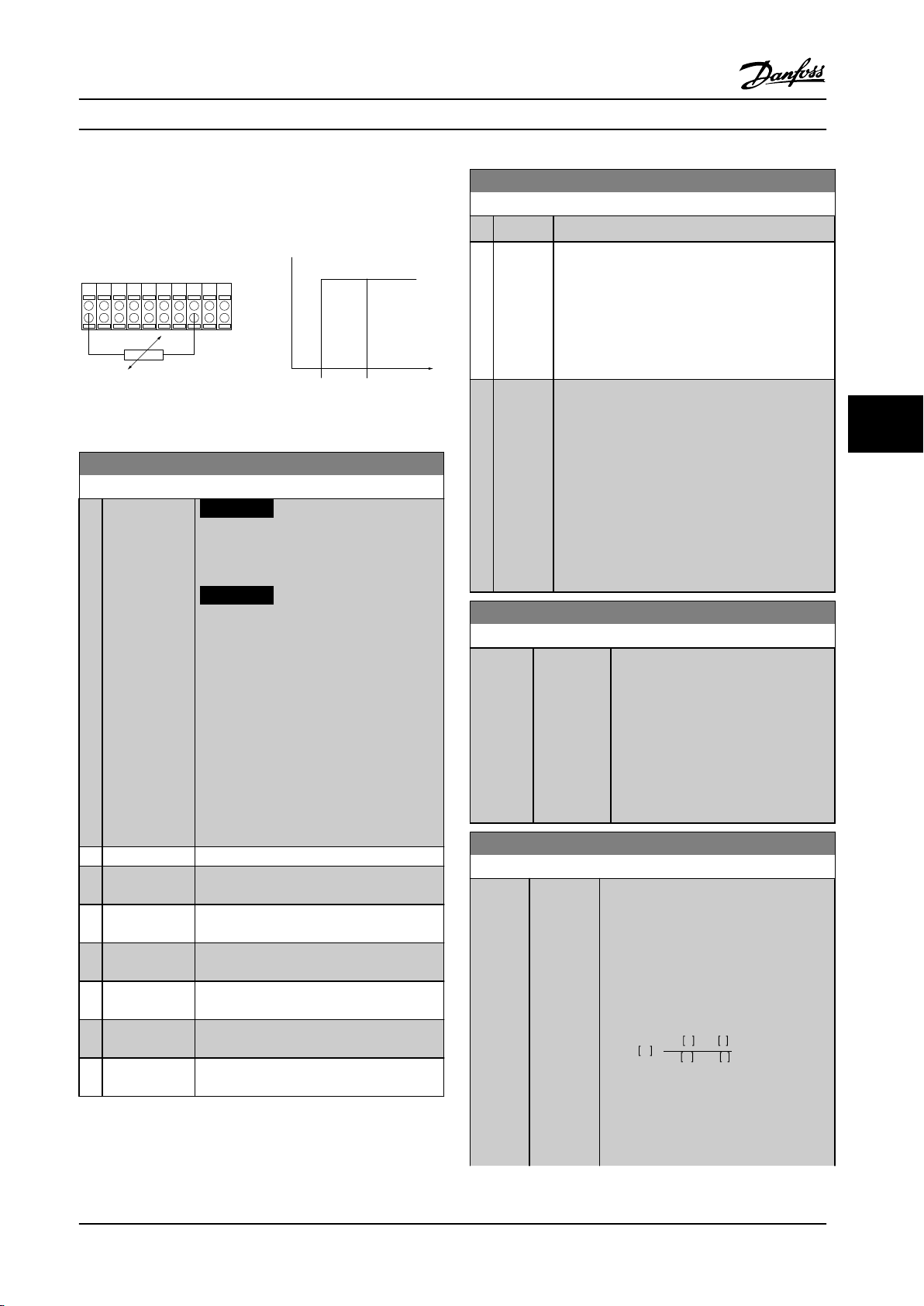
PTC / Thermistor
OFF
ON
+24V
12 13 18 3732
A
2719 29 33B20
GND
R<6.6 k Ω >10.8 k Ω
130BA151.11
Programming Instruction Manual
Parameter set-up:
Set parameter 1-90 Motor Thermal Protection to [2]
Thermistor Trip
Set parameter 1-93 Thermistor Source to [6] Digital Input
Figure 6.6 Klixon Example
1-93 Thermistor Source
Option: Function:
NOTICE!
This parameter cannot be adjusted
while the motor is running.
NOTICE!
Set digital input to [0] PNP - Active at
24 V in 5-00 Digital I/O Mode.
Select the input to which the thermistor
(PTC sensor) should be connected. An
analog input option [1] or [2] cannot be
selected if the analog input is already in use
as a reference source (selected in
3-15 Reference 1 Source, 3-16 Reference 2
Source or 3-17 Reference 3 Source).
When using MCB 112, option [0] None must
always be selected.
[0] None
[1] Analog Input
53
[2] Analog Input
54
[3] Digital input
18
[4] Digital input
19
[5] Digital input
32
[6] Digital input
33
2-10 Brake Function
Option: Function:
[0] Off No brake resistor is installed.
[1] Resistor
brake
[2] AC brake Is selected to improve braking without using a
A brake resistor is incorporated in the system, for
dissipating surplus brake energy as heat.
Connecting a brake resistor allows a higher DC
link voltage during braking (generating operation).
The resistor brake function is only active in
adjustable frequency drives with an integral
dynamic brake.
brake resistor. This parameter controls an
overmagnetization of the motor when running
with a generatoric load. This function can improve
the OVC function. Increasing the electrical losses
in the motor allows the OVC function to increase
the braking torque without exceeding the
overvoltage limit. Note that AC brake is not as
effective as dynamic braking with a resistor.
AC brake is for VVC
open-loop and closed-loop.
plus
and flux mode in both
2-11 Brake Resistor (ohm)
Range: Function:
Size
related*
[ 5.00 -
65535.00
Ohm]
Set the brake resistor value in Ω. This
value is used for monitoring the power
to the brake resistor in 2-13 Brake
Power Monitoring. This parameter is
only active in adjustable frequency
drives with an integral dynamic brake.
Use this parameter for values without
decimals. For a selection with two
decimals, use 30-81 Brake Resistor (ohm).
2-12 Brake Power Limit (kW)
Range: Function:
Size
related*
[ 0.001 -
2000.000
kW]
Parameter 2-12 Brake Power Limit (kW) The
expected average power dissipated in the
brake resistor over a period of 120 s. It is
used as the monitoring limit for
16-33 Brake Energy /2 min and specifies
when a warning/alarm is issued.
To calculate 2–12 Brake Power Limit (kW),
use the following formula:
2
U
V×tbrs
P
br,avg
P
br,avg
the brake resistor
Rbr is the resistance of the brake resistor.
tbr is the active breaking time within the
120 s period, Tbr.
br
W
=
RbrΩ×Tbrs
is the average power dissipated in
6 6
MG37A222 Danfoss A/S © Rev. 2014-02-07 All rights reserved. 59
Page 62

Programming Instruction Manual
2-12 Brake Power Limit (kW)
Range: Function:
Ubr is the DC voltage where the brake
resistor is active, depending on the unit
as follows:
T2 units: 390 V
T4 units: 778 V
T5 units: 810 V
T6 units: 943 V/1099 V for D – F frames
T7 units: 1,099 V
2-15 Brake Check
Option: Function:
Select type of test and monitoring function to check
the connection to the brake resistor, or whether a
brake resistor is present, and then display a warning or
alarm in the event of a fault.
NOTICE!
The brake resistor disconnection function is
tested during power-up. However, the brake
IGBT test is performed when there is no
NOTICE!
If Rbr is not known or if Tbr is
66
2-13 Brake Power Monitoring
Option: Function:
[0] Off No brake power monitoring required.
[1] Warning Activates a warning on the display when the
[2] Trip Trips adjustable frequency drive and displays an
[3] Warning
and trip
different from 120 s, the practical
approach is to run the brake
application, readout 16-33 Brake
Energy /2 min and then enter + 20%
in 2-12 Brake Power Limit (kW).
This parameter is only active in adjustable
frequency drives with an integral dynamic brake.
This parameter enables monitoring of the power
to the brake resistor. The power is calculated
based on the resistance (parameter 2-11 Brake
Resistor (ohm)), the DC link voltage, and the
resistor duty time.
power transmitted over 120 s exceeds 100% of
the monitoring limit (parameter 2-12 Brake Power
Limit (kW)).
The warning disappears when the transmitted
power falls below 80% of the monitoring limit.
alarm when the calculated power exceeds 100%
of the monitoring limit.
Activates both of the above, including warning,
trip and alarm.
[0]
NOTICE!
Remove a warning arising with [0] Off or [1] Warning by
cycling the line power supply. The fault must be
corrected first. For [0] Off or [1] Warning, the adjustable
frequency drive keeps running even if a fault is located.
This parameter is only active in adjustable frequency drives
with an integral dynamic brake.
braking. A warning or trip disconnects the
brake function.
The testing sequence is as follows:
1. The DC link ripple amplitude is measured for
300 ms without braking.
2. The DC link ripple amplitude is measured for
300 ms with the brake turned on.
3. If the DC link ripple amplitude while braking is
lower than the DC link ripple amplitude
before braking + 1%: Brake check has failed by
returning a warning or alarm.
4. If the DC link ripple amplitude while braking is
higher than the DC link ripple amplitude
before braking + 1%: Brake check is OK.
Off Monitors brake resistor and brake IGBT for a short-
circuit during operation. If a short-circuit occurs,
Warning 25 appears.
If power monitoring is set to [0] Off or [1] Warning, the
brake function remains active, even if the monitoring limit
is exceeded, possibly leading to thermal overload of the
resistor. It is also possible to generate a warning via a
relay/digital output. The measuring accuracy of the power
monitoring depends on the accuracy of the resistance of
the resistor (better than ± 20%).
60 Danfoss A/S © Rev. 2014-02-07 All rights reserved. MG37A222
Page 63

Start
term.18
1=on
0=o
Shaft speed
Start delay time
on
o
Brake delay time
Time
Output current
Relay 01
Pre-magnetizing
current or
DC hold current
Reaction time EMK brake
Par 2-20
Release brake current
Par 1-76 Start current/
Par 2-00 DC hold current
Par 1-74
Start speed
Par 2-21
Activate brake
speed
Mechanical brake
locked
Mechanical brake
free
Par 1-71
Par 2-23
130BA074.12
Programming Instruction Manual
6.1.3 2-2* Mechanical Brake
Controlling operation of an electro-magnetic (mechanical) brake, typically required in hoisting applications requires special
parameters.
To control a mechanical brake, a relay output (relay 01 or relay 02) or a programmed digital output (terminal 27 or 29) is
required. Normally, this output must be closed during periods when the adjustable frequency drive is unable to ‘hold’ the
motor, due to an excessive load. Select [32] Mechanical Brake Control for applications with an electro-magnetic brake in
parameter 5-40 Function Relay, 5-30 Terminal 27 Digital Output, or 5-31 Terminal 29 Digital Output. When selecting [32]
Mechanical brake control, the mechanical brake is closed from start-up until the output current is above the level selected in
parameter 2-20 Release Brake Current. During stop, the mechanical brake activates when the speed falls below the level
specified in parameter 2-21 Activate Brake Speed [RPM]. If the adjustable frequency drive enters an alarm condition or an
overcurrent or overvoltage situation, the mechanical brake immediately cuts in, as in the Safe Torque Off function.
NOTICE!
Protection mode and trip delay features (14-25 Trip Delay at Torque Limit and 14-26 Trip Delay at Inverter Fault) can
delay the activation of the mechanical brake in an alarm condition. Disable these features in hoisting applications.
6 6
Figure 6.7 Mechanical Brake Function
MG37A222 Danfoss A/S © Rev. 2014-02-07 All rights reserved. 61
Page 64

Programming Instruction Manual
2-20 Release Brake Current
Range: Function:
Size
related*
[ 0 - par.
16-37 A]
Set the motor current for release of the
mechanical brake, when a start condition
is present. The default value is the
maximum current the inverter can provide
for the particular power size. The upper
limit is specified in 16-37 Inv. Max. Current.
NOTICE!
When Mechanical brake control
output is selected but no
mechanical brake is connected, the
66
2-21 Activate Brake Speed [RPM]
Range: Function:
Size
related*
2-22 Activate Brake Speed [Hz]
Range: Function:
Size related* [ 0 - 5000.0
[0 - 30000
RPM]
Hz]
function will not work by default
setting due to too low motor
current.
Set the motor speed for activation of
the mechanical brake when a stop
condition is present. The upper
speed limit is specified in
4-53 Warning Speed High.
Set the motor frequency for
activation of the mechanical
brake when a stop condition is
present.
2-24 Stop Delay
Range: Function:
0 s* [0 - 5 s] Set the time interval from the moment when the
motor is stopped until the brake closes. This
parameter is a part of the stopping function.
2-25 Brake Release Time
Range: Function:
0.20 s* [0 - 5 s] This value defines the time it takes for the
mechanical brake to open. This parameter
must act as a timeout when brake feedback is
activated.
2-26 Torque Ref
Range: Function:
0 %* [ 0 - 0 %]
2-27 Torque Ramp Up Time
Range: Function:
0.2 s* [0 - 5 s] The value defines the duration of the torque
ramp in clockwise direction.
2-28 Gain Boost Factor
Range: Function:
1 * [0 - 4 ] Only active in flux closed-loop. The function
ensures a smooth transition from torque control
mode to speed control mode when the motor
takes over the load from the brake.
2-23 Activate Brake Delay
Range: Function:
0 s* [0 - 5 s] Enter the brake delay time of the coast after
ramp-down time. The shaft is held at zero speed
with full holding torque. Ensure that the
mechanical brake has locked the load before the
motor enters coast mode.
62 Danfoss A/S © Rev. 2014-02-07 All rights reserved. MG37A222
Page 65
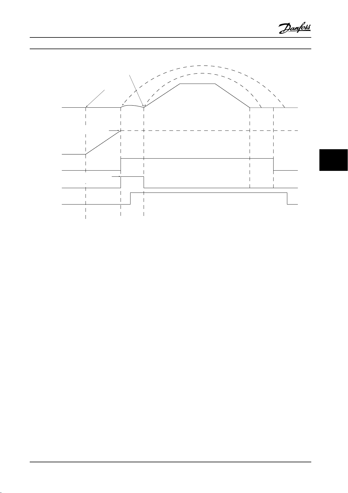
Mech.Brake
GainBoost
Relay
Torqueref.
MotorSpeed
Premag Torque Ramp
Time
p. 2-27
Torque Ref. 2-26
Gain Boost Factor
p. 2-28
Brake
Release
Time
p. 2-25
Ramp 1 upp. 3-41 Ramp 1 downp. 3-42 Stop
Delay
p. 2-24
Activate
Brake
Delay
p. 2-23
1 2 3
130BA642.12
II
I
Programming Instruction Manual
6 6
Figure 6.8 Brake Release Sequence for Hoist Mechanical Brake Control
I) Activate brake delay: The adjustable frequency drive starts again from the mechanical brake engaged position.
II) Stop delay: When the time between successive starts is shorter than the setting in parameter 2-24 Stop Delay, the
adjustable frequency drive starts without applying the mechanical brake (reversing).
MG37A222 Danfoss A/S © Rev. 2014-02-07 All rights reserved. 63
Page 66

Programming Instruction Manual
3-10 Preset Reference
Array [8]
Range: 0–7
Range: Function:
0 %* [-100 - 100 %]
66
Figure 6.9 Preset Reference
Preset ref. bit 2 1 0
Preset ref. 0 0 0 0
Preset ref. 1 0 0 1
Preset ref. 2 0 1 0
Preset ref. 3 0 1 1
Preset ref. 4 1 0 0
Preset ref. 5 1 0 1
Preset ref. 6 1 1 0
Preset ref. 7 1 1 1
Table 6.4 Bits per Preset Reference
3-11 Jog Speed [Hz]
Range: Function:
Size
related*
[ 0 - par.
4-14 Hz]
The jog speed is a fixed output speed
at which the adjustable frequency
drive is running when the jog
function is activated.
See also 3-80 Jog Ramp Time.
3-15 Reference Resource 1
Option: Function:
Select the reference input to be used
for the first reference signal.
parameter 3-15 Reference Resource 1,
parameter 3-16 Reference Resource 2 and
parameter 3-17 Reference Resource 3
define up to three different reference
signals. The sum of these reference
signals defines the actual reference.
[0] No function
[1] Analog Input 53
[2] Analog Input 54
[7] Frequency input
29
[8] Frequency input
33
[11] Local bus
reference
[20] Digital pot.meter
[21] Analog input
X30-11
[22] Analog input
X30-12
[29] Analog Input
X48/2
(General Purpose I/O Option Module)
(General Purpose I/O Option Module)
3-16 Reference Resource 2
Option: Function:
Select the reference input to be used
for the second reference signal.
parameter 3-15 Reference Resource 1,
parameter 3-16 Reference Resource 2
and parameter 3-17 Reference Resource
3 define up to three different reference
signals. The sum of these reference
signals defines the actual reference.
[0] No function
[1] Analog Input 53
[2] Analog Input 54
[7] Frequency input 29
[8] Frequency input 33
[11] Local bus reference
[20] Digital pot.meter
[21] Analog input
X30-11
[22] Analog input
X30-12
[29] Analog Input X48/2
64 Danfoss A/S © Rev. 2014-02-07 All rights reserved. MG37A222
Page 67
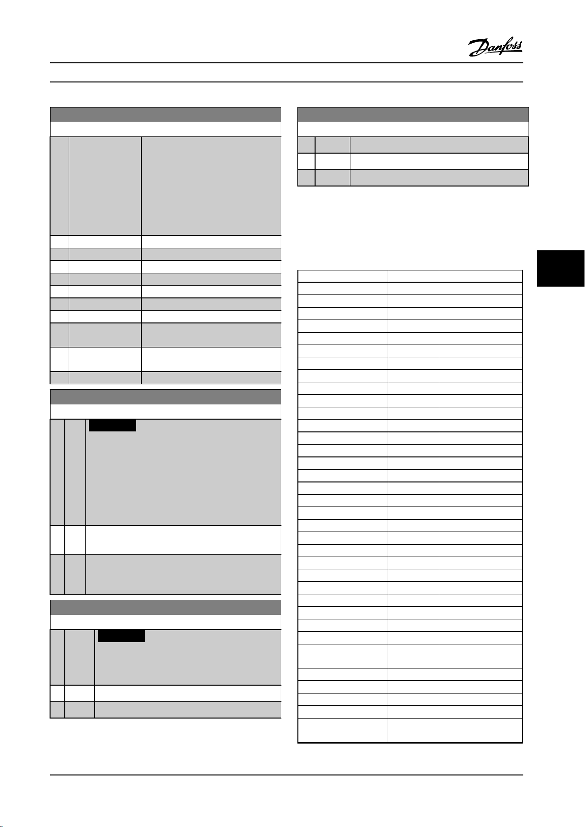
Programming Instruction Manual
3-17 Reference Resource 3
Option: Function:
Select the reference input to be used
for the third reference signal.
parameter 3-15 Reference Resource 1,
parameter 3-16 Reference Resource 2
and parameter 3-17 Reference Resource
3 define up to three different reference
signals. The sum of these reference
signals defines the actual reference.
[0] No function
[1] Analog Input 53
[2] Analog Input 54
[7] Frequency input 29
[8] Frequency input 33
[11] Local bus reference
[20] Digital pot.meter
[21] Analog input
X30-11
[22] Analog input
X30-12
[29] Analog Input X48/2
5-00 Digital I/O Mode
Option: Function:
NOTICE!
Once this parameter has been changed,
perform a power cycle to activate the
parameter.
Digital inputs and programmed digital outputs are preprogrammable for operation either in PNP or NPN
systems.
[0] PNP
[1] NPN
Action on positive directional pulses (↕). PNP systems
are pulled down to GND.
Action on negative directional pulses (↕). NPN systems
are pulled up to +24 V, internally in the adjustable
frequency drive.
5-01 Terminal 27 Mode
Option: Function:
NOTICE!
This parameter cannot be adjusted while the
motor is running.
[0] Input Defines terminal 27 as a digital input.
[1] Output Defines terminal 27 as a digital output.
5-02 Terminal 29 Mode
Option: Function:
This parameter is available for FC 302 only.
[0] Input Defines terminal 29 as a digital input.
[1] Output Defines terminal 29 as a digital output.
6.1.4 Digital Inputs
The digital inputs are used for selecting various functions
in the adjustable frequency drive. All digital inputs can be
set to the following functions:
Digital input function Select Terminal
No operation [0] All *term 32, 33
Reset [1] All
Coast inverse [2] All *term 27
Coast and reset inverse [3] All
Quick stop inverse [4] All
DC brake inverse [5] All
Stop inverse [6] All
Start [8] All *term 18
Latched start [9] All
Reversing [10] All *term 19
Start reversing [11] All
Enable start forward [12] All
Enable start reverse [13] All
Jog [14] All *term 29
Preset reference on [15] All
Preset ref bit 0 [16] All
Preset ref bit 1 [17] All
Preset ref bit 2 [18] All
Freeze reference [19] All
Freeze output [20] All
Speed up [21] All
Slow [22] All
Set-up select bit 0 [23] All
Set-up select bit 1 [24] All
Precise stop inverse [26] 18, 19
Precise start, stop [27] 18, 19
Catch up [28] All
Slow-down [29] All
Counter input [30] 29, 33
Pulse input edge
triggered
Pulse input time based [32] 29, 33
Ramp bit 0 [34] All
Ramp bit 1 [35] All
Latched precise start [40] 18, 19
Latched precise stop
inverse
[31] 29, 33
[41] 18, 19
6 6
MG37A222 Danfoss A/S © Rev. 2014-02-07 All rights reserved. 65
Page 68

Programming Instruction Manual
Digital input function Select Terminal
External interlock [51]
DigiPot increase [55] All
DigiPot decrease [56] All
DigiPot clear [57] All
Digipot hoist [58] All
Counter A (up) [60] 29, 33
Counter A (down) [61] 29, 33
Reset Counter A [62] All
Counter B (up) [63] 29, 33
Counter B (down) [64] 29, 33
Reset counter B [65] All
Mech. brake feedb. [70] All
66
Mech. brake feedb. inv. [71] All
PID error inv. [72] All
PID reset I-part [73] All
PID enable [74] All
PTC card 1 [80] All
Profidrive OFF2 [91]
Profidrive OFF3 [92]
Start edge triggered [98]
Safe option reset [100]
Table 6.5 Digital Input Functions
FC 300 standard terminals are 18, 19, 27, 29, 32 and 33.
MCB 101 terminals are X30/2, X30/3 and X30/4.
[6] Stop
inverse
[8] Start (Default digital input 18): Select start for a
[9] Latched
start
Terminal 29 functions as an output only in FC 302.
Functions dedicated to only one digital input are stated in
[10] Reversing (Default digital input 19). Change the direction
the associated parameter.
All digital inputs can be programmed to these functions:
No
[0]
operation
[1] Reset Resets adjustable frequency drive after a TRIP/
[2] Coast
inverse
[3] Coast and
reset
inverse
[4] Quick stop
inverse
[5] DC brake
inverse
No reaction to signals transmitted to the
terminal.
ALARM. Not all alarms can be reset.
(Default digital input 27): Coasting stop,
inverted input (NC). The adjustable frequency
drive leaves the motor in free mode. Logic ‘0’
⇒ coasting stop.
Reset and coasting stop Inverted input (NC).
Leaves the motor in free mode and resets the
adjustable frequency drive. Logic ‘0’ ⇒ coasting
stop and reset.
Inverted input (NC). Generates a stop in
accordance with the quick-stop ramp time set
in 3-81 Quick Stop Ramp Time. When motor
stops, the shaft is in free mode. Logic ‘0’ ⇒
Quick stop.
Inverted input for DC braking (NC). Stops
motor by energizing it with a DC current for a
[11] Start
reversing
[12] Enable start
forward
[13] Enable start
reverse
[14] Jog (Default digital input 29): Use to activate jog
[15] Preset
reference
on
[16] Preset ref
bit 0
certain time period. See 2-01 DC Brake Current
to 2-03 DC Brake Cut-in Speed [RPM]. The
function is only active when the value in
2-02 DC Braking Time is different from 0.
Logic ’0’ ⇒ DC braking.
Stop inverted function. Generates a stop
function when the selected terminal goes from
logical level ‘1’ to ‘0’. The stop is performed
according to the selected ramp time
(parameter 3-42 Ramp 1 Ramp-down Time,
3-52 Ramp 2 Ramp-down Time, 3-62 Ramp 3
Ramp-down Time, 3-72 Ramp 4 Ramp-down
Time).
NOTICE!
When the adjustable frequency drive is
at the torque limit and has received a
stop command, it does not always stop
by itself. To ensure that the adjustable
frequency drive stops, configure a
digital output to [27] Torque limit & stop
and connect this digital output to a
digital input that is configured as coast.
start/stop command. Logic ‘1’ = start, logic ‘0’
= stop.
The motor starts if a pulse is applied for min. 2
ms. The motor stops when stop inverse is
activated or a reset command (via DI) is given.
of motor shaft rotation. Select logic ‘1’ to
reverse. The reversing signal only changes the
direction of rotation. It does not activate the
start function. Select both directions in
4-10 Motor Speed Direction. The function is not
active in process closed-loop.
Used for start/stop and for reversing on the
same wire. Signals on start are not allowed at
the same time.
Disengages the counter-clockwise movement
and allows for the clockwise direction.
Disengages the clockwise movement and
allows for the counter-clockwise direction.
speed. See parameter 3-11 Jog Speed [Hz].
Shifts between external reference and preset
reference. It is assumed that [1] External/preset
has been selected in 3-04 Reference Function.
Logic '0' = external reference active; logic '1' =
one of the eight preset references is active.
Preset ref. bit 0,1, and 2 enables a choice
between one of the eight preset references
according to Table 6.6.
66 Danfoss A/S © Rev. 2014-02-07 All rights reserved. MG37A222
Page 69

Pulse
Sample time
130BB463.10
Programming Instruction Manual
[17] Preset ref
bit 1
[18] Preset ref
bit 2
Preset ref. bit 2 1 0
Preset ref. 0 0 0 0
Preset ref. 1 0 0 1
Preset ref. 2 0 1 0
Preset ref. 3 0 1 1
Preset ref. 4 1 0 0
Preset ref. 5 1 0 1
Preset ref. 6 1 1 0
Preset ref. 7 1 1 1
Table 6.6 Preset Ref. Bit
[19] Freeze
ref
[20] Freeze
output
Same as Preset ref bit 0 [16].
Same as Preset ref bit 0 [16].
Freezes the actual reference which is now the
point of enable/condition for speed up and slow. If
using speed up/down, the speed change always
follows ramp 2 (3-51 Ramp 2 Ramp-up Time and
3-52 Ramp 2 Ramp-down Time) in the range 0 -
parameter 3-03 Maximum Reference.
Freezes the actual motor frequency (Hz), which is
now the point of enable/condition for speed up
and slow to be used. If using speed up/down, the
speed change always follows ramp 2 (3-51 Ramp 2
Ramp-up Time and 3-52 Ramp 2 Ramp-down Time)
in the range 0 - parameter 1-23 Motor Frequency.
NOTICE!
When Freeze output is active, the
adjustable frequency drive cannot be
stopped via a low [8] start signal. Stop the
adjustable frequency drive via a terminal
programmed for [2] coasting inverse or [3]
coast and reset, inverse.
[21] SpeedupIf digital control of the up/down speed is desired
(motor potentiometer), select speed up and slow.
Activate this function by selecting either freeze
reference or freeze output. When speed up/down
is activated for less than 400 ms, the resulting
reference is increased/decreased by 0.1%. If Speed
up/down is activated for more than 400 ms, the
resulting reference follows the setting in ramping
up/down parameter 3-x1/3-x2.
Shut down Catch up
Unchanged speed 0 0
Reduced by %-value 1 0
Increased by %-value 0 1
Reduced by %-value 1 1
[22] Slow
[23] Set-up
select bit
0
[24] Set-up
select bit
1
[26] Precise
stop inv.
[27] Precise
start, stop
[28]Catch up Increases reference value by percentage
[29] Slow-
down
[30] Counter
input
[31] Pulse
edge
triggered
Same as [21] Speed-up.
Select set-up select bit 0 or select set-up select
bit 1 to select one of the four set-ups. Set
0-10 Active Set-up to multi set-up.
(Default digital input 32): Same as [23] Set-up
select bit 0.
Sends an inverted stop signal when the precise
stop function is activated in 1-83 Precise Stop
Function.
Precise stop inverse function is available for
terminals 18 or 19.
Use when [0] Precise ramp stop is selected in
1-83 Precise Stop Function.
Precise start, stop is available for terminals 18
and 19.
Precise start ensures that the rotor angle from
standing still to reference is the same for each
start (for same ramp time, same setpoint). This
is the equivalent to the precise stop where the
angle that the rotor turns from reference to
standstill is the same for each stop.
When using for 1-83 Precise Stop Function [1] or
[2]:
The adjustable frequency drive needs a precise
stop signal before the value of 1-84 Precise Stop
Counter Value is reached. If this value is not
supplied, the adjustable frequency drive does
not stop when the value in 1-84 Precise Stop
Counter Value is reached.
A digital input triggers precise start, stop and is
available for terminals 18 and 19.
(relative) set in 3-12 Catch up/slow-down value.
Reduces reference value by percentage
(relative) set in 3-12 Catch up/slow-down value.
Precise stop function in 1-83 Precise Stop
Function acts as counter stop or speed
compensated counter stop with or without
reset. The counter value must be set in
1-84 Precise Stop Counter Value.
Edge-triggered pulse input counts the number
of pulse flanks per sample time. This number
gives a higher resolution at high frequencies,
but is not as precise at lower frequencies. Use
this pulse principle for encoders with low
resolution (30 ppr, for example).
Figure 6.10 Pulse vs. Sample Time
6 6
MG37A222 Danfoss A/S © Rev. 2014-02-07 All rights reserved. 67
Page 70
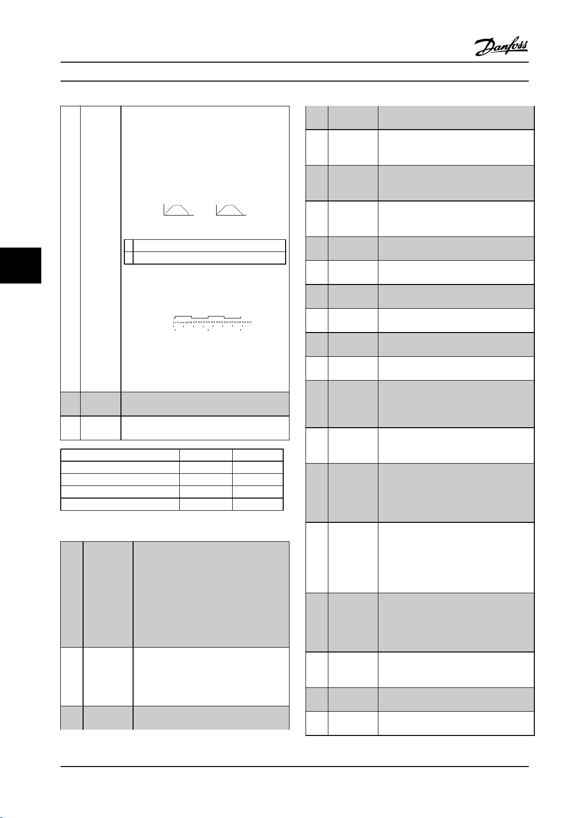
Speed [rpm] Spee d [rpm]
Time[sec] Time[sec]a b
130BB462.10
Read Timer:
20 timer tides
Read Timer:
20 timer tides
Time Start
Time counter
Sample time
Timer
Pulse
130BB464.10
Programming Instruction Manual
[32] Pulse
timebased
Time-based pulse input measures the duration
between flanks. This number gives a higher
resolution at lower frequencies, but is not as
precise at higher frequencies. This principle has
a cut-off frequency that makes it unsuited for
encoders with low resolutions (30 ppr) at low
speeds.
[55] DigiPot
increase
[56] DigiPot
decrease
treated in the same way as an internally
generated alarm.
INCREASE signal to the digital potentiometer
function described in parameter group 3-9*
Digital Pot.Meter
DECREASE signal to the digital potentiometer function described in parameter
group 3-9* Digital Pot.Meter
[57] DigiPot Clear Clears the digital potentiometer reference
described in parameter group 3-9* Digital
Pot.Meter
a Low encoder resolution
b Standard encoder resolution
66
Figure 6.11 Encoder Resolution Comparison
[60] Counter A (Terminal 29 or 33 only) Input for increment
counting in the SLC counter.
[61] Counter A (Terminal 29 or 33 only) input for
decrement counting in the SLC counter.
[62] Reset
Input for reset of counter A.
Counter A
[63] Counter B (Terminal 29 or 33 only) Input for increment
counting in the SLC counter.
[64] Counter B (Terminal 29 or 33 only) Input for
decrement counting in the SLC counter.
Figure 6.12 Time Based Pulse Input
[65] Reset
Input for reset of counter B.
Counter B
[34] Ramp bit0Enables a choice between one of the four
ramps available, according to Table 6.7.
[35] Ramp bit1Same as Ramp bit 0.
Preset ramp bit 1 0
Ramp 1 0 0
Ramp 2 0 1
Ramp 3 1 0
Ramp 4 1 1
[70] Mech. Brake
Feedback
[71] Mech. Brake
Feedback
inv.
[72] PID error
inverse
Brake feedback for hoisting applications: Set
1-01 Motor Control Principle to [3] Flux w/
motor feedback; set 1-72 Start Function to [6]
Hoist mech brake Ref.
Inverted brake feedback for hoisting
applications
When enabled, it inverts the resulting error
from the process PID controller. Available
only if configuration mode is set to "Surface
Winder", "Extended PID Speed OL" or
"Extended PID Speed CL".
Table 6.7
Latched
[40]
Precise Start
[41] Latched
Precise Stop
inverse
[51] External
interlock
A latched precise start only requires a pulse
of 3 ms on T18 or T19.
When using for 1–83 [1] or [2]:
When the reference is reached, the
adjustable frequency drive internally enables
the precise stop signal. The adjustable
frequency drive does the precise stop when
the counter value of 1-84 Precise Stop
Counter Value is reached.
Sends a latched stop signal when the
precise stop function is activated in
1-83 Precise Stop Function. The latched
precise stop inverse function is available for
terminals 18 or 19.
This function makes it possible to give an
external fault to the drive. This fault is
[73] PID reset I-
part
When enabled, resets the I-part of the
process PID controller. Equivalent to
7-40 Process PID I-part Reset. Available only if
configuration mode is set to "Surface
Winder," "Extended PID Speed OL," or
"Extended PID Speed CL".
[74] PID enable Enables the extended process PID controller.
Equivalent to 7-50 Process PID Extended PID.
Available only if configuration mode is set
to "Extended PID Speed OL" or "Extended
PID Speed CL."
[80] PTC Card 1
All digital inputs can be set to [80] PTC Card
1. However, only one digital input must be
set to this choice.
[91] Profidrive
OFF2
[92] Profidrive
OFF3
The functionality is the same as the control
word bit of the profibus/profinet option.
The functionality is the same as the control
word bit of the profibus/profinet option.
68 Danfoss A/S © Rev. 2014-02-07 All rights reserved. MG37A222
Page 71

Programming Instruction Manual
[98] Start edge
triggered
[100] Safe Option
Reset
Edge triggered start command. Keeps the
start command alive, even if the input is
going back to low. Can be used for a start
push button.
6.1.5 5–3* Digital Outputs
The two solid-state digital outputs are common for
terminals 27 and 29. Set the I/O function for terminal 27 in
5–01 Terminal 27 Mode, and set the I/O function for
terminal 29 in parameter 5-02 Terminal 29 Mode.
NOTICE!
These parameters cannot be adjusted while the motor is
running.
[0] No operation Default for all digital outputs and relay
outputs
[1] Control ready The control card is ready. For example, the
control is supplied by an external 24 V
(MCB 107) and the main power to the unit
is not detected.
[2] Drive ready The adjustable frequency drive is ready for
operation and applies a supply signal on
the control board.
[3] Drive ready/
remote
control
[4] Enable/no
warning
[5] VLT running Motor is running and shaft torque is
[6] Running/no
warning
[7] Run in
range/no
warning
[8] Run on
reference/no
warning
[9] Alarm An alarm activates the output. No
[10] Alarm or
warning
[11] At torque
limit
The adjustable frequency drive is ready for
operation and is in [Auto on] mode.
Ready for operation. No start or stop
command given (start/disable). No
warnings are active.
present.
Output speed is higher than the speed set
in 1-81 Min Speed for Function at Stop
[RPM]. The motor is running and there are
no warnings.
Motor is running within the programmed
current and speed ranges set in
4-50 Warning Current Low to 4-53 Warning
Speed High. There are no warnings.
Motor runs at reference speed. No
warnings.
warnings.
An alarm or a warning activates the
output.
The torque limit set in 4-16 Torque Limit
Motor Mode or 4-17 Torque Limit Generator
Mode has been exceeded.
[12] Out of current
range
[13] Below current,
low
[14] Above
current, high
[15] Out of speed
range
[16] Below speed,
low
[17] Above speed,
high
[18] Out of
feedback
range
[19] Below
feedback low
[20] Above
feedback high
[21] Thermal
warning
[22] Ready, no
thermal
warning
[23] Remote,
ready, no
thermal
warning
[24] Ready, no
over/under
voltage
[25] Reverse
[26] Bus OK Active communication (no timeout) via the
[27] Torque limit
and stop
[28] Brake, no
brake warning
[29] Brake ready,
no fault
The motor current is outside the range set
in 4-18 Current Limit.
Motor current is lower than that set in
4-50 Warning Current Low.
Motor current is higher than that set in
4-51 Warning Current High.
Output frequency is outside the frequency
ranges set in 4-52 Warning Speed Low and
4-53 Warning Speed High.
Output speed is lower than the setting in
4-52 Warning Speed Low.
Output speed is higher than the setting in
4-53 Warning Speed High.
Feedback is outside the range set in
4-56 Warning Feedback Low and
4-57 Warning Feedback High.
Feedback is below the limit set in
4-56 Warning Feedback Low.
Feedback is above the limit set in
4-57 Warning Feedback High.
The thermal warning turns on when the
temperature exceeds the limit in the
motor
•
adjustable frequency drive
•
brake resistor
•
thermistor
•
The adjustable frequency drive is ready for
operation and there is no overtemperature
warning.
The adjustable frequency drive is ready for
operation and is in [Auto on] mode. There
is no overtemperature warning.
The adjustable frequency drive is ready for
operation and the AC line voltage is within
the specified voltage range (see
chapter 11 Specifications).
Reversing. Logic ‘1’ when CW rotation of
the motor. Logic ‘0’ when CCW rotation of
the motor. If the motor is not rotating the
output follows the reference.
serial communication port.
Use in performing a coasting stop and in
torque limit condition. If the adjustable
frequency drive has received a stop signal
and is at the torque limit, the signal is
Logic ‘0’.
Brake is active and there are no warnings.
Brake is ready for operation and there are
no faults.
6 6
MG37A222 Danfoss A/S © Rev. 2014-02-07 All rights reserved. 69
Page 72

Programming Instruction Manual
[30] Brake fault
(IGBT)
[31] Relay 123 Relay is activated when control word [0] is
[32] Mechanical
brake control
[33] Safe stop
66
activated (FC
302 only)
[40] Out of ref
range
[41] Below
reference low
[42] Above
reference high
[43] Extended PID
Limit
[45] Bus Ctrl Controls output via bus. The state of the
[46] Bus Ctrl On at
timeout
[47] Bus Ctrl Off at
timeout
[51] MCO
controlled
[55] Pulse output
[60] Comparator 0
[61] Comparator 1
[62] Comparator 2
[63] Comparator 3
Output is logic ‘1’ when the brake IGBT is
short-circuited. Use this function to protect
the adjustable frequency drive if there is a
fault on the brake modules. Use the
output/relay to cut out the line voltage
from the adjustable frequency drive.
selected in parameter group 8-**
Communications and Options.
Enables control of an external mechanical
brake, see description in chapter 6.1.3 2-2*
Mechanical Brake.
Indicates that the safe stop on terminal 37
has been activated.
Active when the actual speed is outside
settings in 4-52 Warning Speed Low to
4-55 Warning Reference High.
Active when actual speed is below speed
reference setting.
Active when actual speed is above speed
reference setting
output is set in 5-90 Digital & Relay Bus
Control. The output state is retained in the
event of bus timeout.
Controls output via bus. The state of the
output is set in 5-90 Digital & Relay Bus
Control. If bus timeout, the output state is
set high (On).
Controls output via bus. The state of the
output is set in 5-90 Digital & Relay Bus
Control. If bus timeout, the output state is
set low (Off).
Active when an MCO 302 or MCO 305 is
connected. The output is controlled from
option.
See parameter group 13-1* Comparators. If
comparator 0 is evaluated as TRUE, the
output goes high. Otherwise, it is low.
See parameter group 13-1* Comparators. If
comparator 1 is evaluated as TRUE, the
output goes high. Otherwise, it is low.
See parameter group 13-1* Comparators. If
comparator 2 is evaluated as TRUE, the
output goes high. Otherwise, it is low.
See parameter group 13-1* Comparators. If
comparator 3 is evaluated as TRUE, the
output goes high. Otherwise, it is low.
[64] Comparator 4
[65] Comparator 5
[70] Logic Rule 0
[71] Logic Rule 1
[72] Logic Rule 2
[73] Logic Rule 3
[74] Logic Rule 4
[75] Logic Rule 5
[80] SL Digital
Output A
[81] SL Digital
Output B
[82] SL Digital
Output C
[83] SL Digital
Output D
[84] SL Digital
Output E
[85] SL Digital
Output F
See parameter group 13-1* Comparators. If
comparator 4 is evaluated as TRUE, the
output goes high. Otherwise, it is low.
See parameter group 13-1* Comparators. If
comparator 5 is evaluated as TRUE, the
output goes high. Otherwise, it is low.
See parameter group 13-4* Logic Rules. If
logic rule 0 is evaluated as TRUE, the
output goes high. Otherwise, it is low.
See parameter group 13-4* Logic Rules. If
logic rule 1 is evaluated as TRUE, the
output goes high. Otherwise, it is low.
See parameter group 13-4* Logic Rules. If
logic rule 2 is evaluated as TRUE, the
output goes high. Otherwise, it is low.
See parameter group 13-4* Logic Rules. If
logic rule 3 is evaluated as TRUE, the
output goes high. Otherwise, it is low.
See parameter group 13-4* Logic Rules. If
logic rule 4 is evaluated as TRUE, the
output goes high. Otherwise, it is low.
See parameter group 13-4* Logic Rules. If
logic rule 5 is evaluated as TRUE, the
output goes high. Otherwise, it is low.
See 13-52 SL Controller Action. The output
goes high whenever the smart logic action
[38] Set dig. out. A high is executed. The
output goes low whenever the smart logic
action [32] Set dig. out. A low is executed.
See 13-52 SL Controller Action. The input
goes high whenever the smart logic action
[39] Set dig. out. A high is executed. The
input goes low whenever the smart logic
action [33] Set dig. out. A low is executed.
See 13-52 SL Controller Action. The input
goes high whenever the smart logic action
[40] Set dig. out. A high is executed. The
input goes low whenever the Smart Logic
Action [34] Set dig. out. A low is executed.
See 13-52 SL Controller Action. The input
goes high whenever the smart logic action
[41] Set dig. out. A high is executed. The
input goes low whenever the smart logic
action [35] Set dig. out. A low is executed.
See 13-52 SL Controller Action. The input
goes high whenever the smart logic action
[42] Set dig. out. A high is executed. The
input goes low whenever the smart logic
action [36] Set dig. out. A low is executed.
See 13-52 SL Controller Action. The input
goes high whenever the smart logic action
[43] Set dig. out. A high is executed. The
input goes low whenever the smart logic
action [37] Set dig. out. A low is executed.
70 Danfoss A/S © Rev. 2014-02-07 All rights reserved. MG37A222
Page 73

Programming Instruction Manual
[120] Local
reference
active
Output is high when 3-13 Reference Site =
[2] Local or when 3-13 Reference Site = [0]
Linked to hand auto at the same time as
the LCP is in [Hand on] mode.
Reference site set
in 3-13 Reference
Site
Reference site:
Local
3-13 Reference
Site [2]
Reference site:
Remote
3-13 Reference
Site [1]
Reference site:
Linked to Hand/
Auto
Hand 1 0
Hand ⇒ off
Auto ⇒ off
Auto 0 1
Table 6.8 Local and Remote Reference
Local
refer-
ence
active
[120]
1 0
0 1
1 0
0 0
Remote
reference
active [121]
[152] ATEX ETR freq.
alarm
[153] ATEX ETR cur.
warning
[154] ATEX ETR freq.
warning
[188] AHF Capacitor
Connect
[189] External fan
control
Selectable if parameter 1-90 Motor Thermal
Protection is set to [20] Above feedback
high or [21] Thermal warning. If the alarm
166 ATEX ETR freq.lim.alarm is active, the
output is 1.
Selectable ifparameter 1-90 Motor Thermal
Protection is set to [20] Above feedback
high or [21] Thermal warning. If the alarm
163 ATEX ETR cur.lim.warning is active, the
output is 1.
Selectable if parameter 1-90 Motor Thermal
Protection is set to [20] Above feedback
high or [21] Thermal warning. If the
warning 165 ATEX ETR freq.lim.warning is
active, the output is 1.
The capacitors are turned on at 20%
(hysteresis of 50% gives an interval of
10%–30%). The capacitors are disconnected below 10%. The off delay is 10 s
and restart if the nominal power goes
above 10% during the delay. 5-80 AHF Cap
Reconnect Delay is used to guarantee a
minimum off-time for the capacitors.
The internal logic for the internal fan
control is transferred to this output to
make it possible to control an external fan
(relevant for HP duct cooling).
6 6
Remote
[121]
reference
active
[122] No alarm Output is high when no alarm is present.
[123] Start
command
active
[124] Running
reverse
[125] Drive in hand
mode
[126] Drive in auto
mode
[151] ATEX ETR cur.
alarm
Output is high when 3-13 Reference Site
=[1] Remote or [0] Linked to hand/auto
while the LCP is in [Auto on] mode. See
Table 6.8.
Output is high when there is an active
start command (via digital input bus
connection or [Hand on] or [Auto on]), and
no stop or start command is active.
Output is high when the adjustable
frequency drive is running counter
clockwise (the logical product of the status
bits ‘running’ and ‘reverse’).
Output is high when the adjustable
frequency drive is in hand on mode (as
indicated by the LED light above [Hand
on]).
Output is high when the adjustable
frequency drive is in [Hand on] mode (as
indicated by the LED light above [Auto
on]).
Selectable if parameter 1-90 Motor Thermal
Protection is set to [20] Above feedback
high or [21] Thermal warning. If the alarm
164 ATEX ETR cur.lim.alarm is active, the
output is 1.
5-40 Function Relay
Array [9]
(Relay 1 [0], Relay 2 [1], Relay 3 [2] (MCB 113), Relay 4 [3] (MCB
113), Relay 5 [4] (MCB 113), Relay 6 [5] (MCB 113), Relay 7 [6]
(MCB 105), Relay 8 [7] (MCB 105), Relay 9 [8] (MCB 105))
Option: Function:
[0] No operation All digital and relay outputs are
default set to “No Operation.”
[1] Control ready The control card is ready. Control is
supplied by an external 24 V (MCB
107) and the main power to the
adjustable frequency drive is not
detected.
[2] Drive ready Adjustable frequency drive is ready to
operate. Line power and control
supplies are OK.
[3] Drive rdy/rem ctrl The adjustable frequency drive is
ready for operation and is in auto on
mode.
[4] Enable / no
warning
[5] Running Motor is running, and shaft torque
Ready for operation. No start or stop
commands have been applied (start/
disable). No warnings are active.
present.
MG37A222 Danfoss A/S © Rev. 2014-02-07 All rights reserved. 71
Page 74

Programming Instruction Manual
5-40 Function Relay
Array [9]
(Relay 1 [0], Relay 2 [1], Relay 3 [2] (MCB 113), Relay 4 [3] (MCB
113), Relay 5 [4] (MCB 113), Relay 6 [5] (MCB 113), Relay 7 [6]
(MCB 105), Relay 8 [7] (MCB 105), Relay 9 [8] (MCB 105))
Option: Function:
[6] Running / no
warning
[7] Run in range/no
warn
66
[8] Run on ref/no
warn
[9] Alarm An alarm activates the output. No
[10] Alarm or warning An alarm or a warning activates the
[11] At torque limit
[12] Out of current
range
[13] Below current, low Motor current is lower than that set
[14] Above current,
high
[15] Out of speed
range
[16] Below speed, low Output speed is lower than the
[17] Above speed, high Output speed is higher than the
[18] Out of feedb.
range
[19] Below feedback,
low
[20] Above feedback,
high
[21] Thermal warning Thermal warning turns on when the
Output speed is higher than the
speed set in 1-81 Min Speed for
Function at Stop [RPM]. The motor is
running and no warnings are active.
Motor is running within the
programmed current and speed
ranges set in 4-50 Warning Current
Low and 4-53 Warning Speed High. No
warnings are active.
Motor runs at reference speed. No
warnings are active.
warnings are active.
output.
The torque limit set in 4-16 Torque
Limit Motor Mode or 4-17 Torque Limit
Generator Mode has been exceeded.
The motor current is outside the
range set in .
in 4-50 Warning Current Low.
Motor current is higher than that set
in 4-51 Warning Current High.
Output speed/frequency is outside
the frequency ranges set in
4-52 Warning Speed Low and
4-53 Warning Speed High.
setting in 4-52 Warning Speed Low
setting in 4-53 Warning Speed High.
Feedback is outside the range set in
4-56 Warning Feedback Low and
4-57 Warning Feedback High.
Feedback is below the limit set in
4-56 Warning Feedback Low.
Feedback is above the limit set in
4-57 Warning Feedback High.
temperature exceeds the limit either
in motor, adjustable frequency drive,
5-40 Function Relay
Array [9]
(Relay 1 [0], Relay 2 [1], Relay 3 [2] (MCB 113), Relay 4 [3] (MCB
113), Relay 5 [4] (MCB 113), Relay 6 [5] (MCB 113), Relay 7 [6]
(MCB 105), Relay 8 [7] (MCB 105), Relay 9 [8] (MCB 105))
Option: Function:
brake resistor, or connected
thermistor.
[22] Ready,no thermalWThe adjustable frequency drive is
ready for operation and there is no
overtemperature warning.
[23] Remote,ready,noTWThe adjustable frequency drive is
ready for operation and is in Auto On
mode. There is no overtemperature
warning.
[24] Ready, Voltage OK The adjustable frequency drive is
ready for operation and the AC line
voltage is within the specified voltage
range (see chapter 11 Specifications).
[25] Reverse Logic ‘1’ when CW rotation of the
motor. Logic ‘0’ when CCW rotation of
the motor. If the motor is not
rotating, the output follows the
reference.
[26] Bus OK Active communication (no timeout)
via the serial communication port.
[27] Torque limit stop Use in performing a coasted stop and
adjustable frequency drive in torque
limit condition. If the adjustable
frequency drive has received a stop
signal and is at the torque limit, the
signal is Logic ‘0’.
[28] Brake: No Brake
War
[29] Brake ready, no
fault
[30] Brake fault (IGBT) Output is Logic ‘1’ when the brake
[31] Relay 123 Digital output/relay is activated when
Brake is active and there are no
warnings.
Brake is ready for operation and there
are no faults.
IGBT is short-circuited. Use this
function to protect the adjustable
frequency drive if there is a fault on
the brake module. Use the digital
output/relay to cut out the AC line
voltage from the adjustable frequency
drive.
Control Word [0] is selected in
parameter group 8-** Communication
and Options..
72 Danfoss A/S © Rev. 2014-02-07 All rights reserved. MG37A222
Page 75

Programming Instruction Manual
5-40 Function Relay
Array [9]
(Relay 1 [0], Relay 2 [1], Relay 3 [2] (MCB 113), Relay 4 [3] (MCB
113), Relay 5 [4] (MCB 113), Relay 6 [5] (MCB 113), Relay 7 [6]
(MCB 105), Relay 8 [7] (MCB 105), Relay 9 [8] (MCB 105))
Option: Function:
[32] Mech brake ctrl Selection of mechanical brake control.
When selected parameters in
parameter group 2-2* Mechanical
Brake are active. The output must be
reinforced to carry the current for the
coil in the brake. Solved by
connecting an external relay to the
selected digital output.
[33] Safe stop active (FC 302 only) Indicates that the safe
stop on terminal 37 has been
activated.
[36] Control word bit11Activate relay 1 via control word from
serial communication bus. No other
functional impact in the adjustable
frequency drive. Typical application:
Controlling auxiliary devices from
serial communication bus. The
function is valid when [0] FC profile in
8-10 Control Word Profile is selected.
[37] Control word bit12Activate relay 2 (FC 302 only) by
control word from serial communication bus. No other functional
impact in the adjustable frequency
drive. Typical application: controlling
auxiliary device from the serial
communication bus. The function is
valid when [0] FC profile in
8-10 Control Word Profile is selected.
[38] Motor feedb. error Failure in the speed feedback loop
from motor running in closed-loop.
The output can eventually be used to
prepare switching the adjustable
frequency drive in open-loop in the
case of an emergency.
[39] Tracking error When the difference between
calculated speed and actual speed in
4-35 Tracking Error is larger than
selected the digital output/relay is
active.
[40] Out of ref range Active when the actual speed is
outside settings in 4-52 Warning Speed
Low to 4-55 Warning Reference High.
[41] Below reference,
low
Active when actual speed is below
speed reference setting.
5-40 Function Relay
Array [9]
(Relay 1 [0], Relay 2 [1], Relay 3 [2] (MCB 113), Relay 4 [3] (MCB
113), Relay 5 [4] (MCB 113), Relay 6 [5] (MCB 113), Relay 7 [6]
(MCB 105), Relay 8 [7] (MCB 105), Relay 9 [8] (MCB 105))
Option: Function:
[42] Above ref, high Active when actual speed is above
speed reference setting.
[43] Extended PID Limit
[45] Bus ctrl. Controls digital output/relay via bus.
The state of the output is set in
5-90 Digital & Relay Bus Control. The
output state is retained in the event
of bus timeout.
[46] Bus ctrl, 1 if
timeout
[47] Bus ctrl, 0 if
timeout
[51] MCO controlled Active when an MCO 302 or MCO 305
[60] Comparator 0
[61] Comparator 1
[62] Comparator 2
[63] Comparator 3
[64] Comparator 4
[65] Comparator 5
Controls output via bus. The state of
the output is set in 5-90 Digital &
Relay Bus Control. If bus timeout, the
output state is set high (On).
Controls output via bus. The state of
the output is set in 5-90 Digital &
Relay Bus Control. In the event of a
bus timeout, the output state is set to
low (Off).
is connected. The output is controlled
from an option.
See parameter group 13-1* Smart
Logic Control. If Comparator 0 in SLC
is true, the output goes high.
Otherwise, it is low.
See parameter group 13-1* Smart
Logic Control. If Comparator 1 in SLC
is true, the output goes high.
Otherwise, it is low.
See parameter group 13-1* Smart
Logic Control. If Comparator 2 in SLC
is true, the output goes high.
Otherwise, it is low.
See parameter group 13-1* Smart
Logic Control. If Comparator 3 in SLC
is true, the output goes high.
Otherwise, it is low.
See parameter group 13-1* Smart
Logic Control. If Comparator 4 in SLC
is true, the output goes high.
Otherwise, it is low.
See parameter group 13-1* Smart
Logic Control. If Comparator 5 in SLC
is true, the output goes high.
Otherwise, it is low.
6 6
MG37A222 Danfoss A/S © Rev. 2014-02-07 All rights reserved. 73
Page 76

Programming Instruction Manual
5-40 Function Relay
Array [9]
(Relay 1 [0], Relay 2 [1], Relay 3 [2] (MCB 113), Relay 4 [3] (MCB
113), Relay 5 [4] (MCB 113), Relay 6 [5] (MCB 113), Relay 7 [6]
(MCB 105), Relay 8 [7] (MCB 105), Relay 9 [8] (MCB 105))
Option: Function:
[70] Logic rule 0
[71] Logic rule 1
66
[72] Logic rule 2
[73] Logic rule 3 See parameter group 13-4*(Smart
[74] Logic rule 4
[75] Logic rule 5
[80] SL digital output A
[81] SL digital output B
[82] SL digital output C
[83] SL digital output D
See parameter group 13-4* Logic
Rules. If Logic Rule 0 in SLC is true,
the output goes high. Otherwise, it is
low.
See parameter group 13-4* Logic
Rules. If Logic Rule 1 in SLC is true,
the output goes high. Otherwise, it is
low.
See parameter group 13-4* Logic
Rules. If Logic Rule 2 in SLC is true,
the output goes high. Otherwise, it is
low.
Logic Control). If Logic Rule 3 in SLC
is true, the output goes high.
Otherwise, it is low.
See parameter group 13-4* Logic
Rules. If Logic Rule 4 in SLC is true,
the output goes high. Otherwise, it is
low.
See parameter group 13-4* Logic
Rules. If Logic Rule 5 in SLC is true,
the output goes high. Otherwise, it is
low.
See 13-52 SL Controller Action. Output
A is low on smart logic action [32] Set
digital out A low. Output A is high on
smart logic action [38] Set digital out A
high.
See 13-52 SL Controller Action. Output
B is low on smart logic action [33] Set
digital out B low. Output B is high on
smart logic action [39] Set digital out B
high.
See 13-52 SL Controller Action. Output
C is low on smart logic action [34] Set
digital out C low. Output C is high on
smart logic action [40] Set digital out C
high.
See 13-52 SL Controller Action. Output
D is low on smart logic action [35] Set
digital out D low. Output D is high on
smart logic action [41] Set digital out
D high.
5-40 Function Relay
Array [9]
(Relay 1 [0], Relay 2 [1], Relay 3 [2] (MCB 113), Relay 4 [3] (MCB
113), Relay 5 [4] (MCB 113), Relay 6 [5] (MCB 113), Relay 7 [6]
(MCB 105), Relay 8 [7] (MCB 105), Relay 9 [8] (MCB 105))
Option: Function:
[84] SL digital output E
[85] SL digital output F
[120] Local ref active
Remote ref active
[121]
[122] No alarm Output is high when no alarm is
See 13-52 SL Controller Action. Output
E is low on smart logic action [36] Set
digital out E low. Output E is high on
smart logic action [42] Set digital out E
high.
See 13-52 SL Controller Action. Output
F is low on smart logic action [37] Set
digital out F low. Output F is high on
smart logic action [43] Set digital out F
high.
Output is high when 3-13 Reference
Site = [2] Local or when 3-13 Reference
Site = [0] Linked to Hand/Auto at the
same time as the LCP is in [Hand on]
mode.
Reference site
set in
3-13 Reference
Site
Reference site:
Local
3-13 Reference
Site [2]
Reference site:
Remote
3-13 Reference
Site [1]
Reference site:
Linked to Hand/
Auto
Hand 1 0
Hand ⇒ off
Auto ⇒ off
Auto 0 1
Table 6.9 Local and Remote
Reference
Output is high when 3-13 Reference
Site = [1] Remote or [0] Linked to
Hand/Auto while the LCP is in [Auto
on] mode. See Table 6.9.
present.
Local
refer-
ence
active
[120]
1 0
0 1
1 0
0 0
Remote
reference
active
[121]
74 Danfoss A/S © Rev. 2014-02-07 All rights reserved. MG37A222
Page 77

Programming Instruction Manual
5-40 Function Relay
Array [9]
(Relay 1 [0], Relay 2 [1], Relay 3 [2] (MCB 113), Relay 4 [3] (MCB
113), Relay 5 [4] (MCB 113), Relay 6 [5] (MCB 113), Relay 7 [6]
(MCB 105), Relay 8 [7] (MCB 105), Relay 9 [8] (MCB 105))
Option: Function:
[123] Start command
activ
[124] Running reverse Output is high when the adjustable
[125] Drive in hand
mode
[126] Drive in auto
mode
[151] ATEX ETR cur.
alarm
[152] ATEX ETR freq.
alarm
[153] ATEX ETR cur.
warning
[154] ATEX ETR freq.
warning
[188] AHF Capacitor
Connect
[189] External Fan
Control
Output is high when the start
command is high (via digital input,
bus connection or [Hand on] or [Auto
on]), and a stop has been the last
command.
frequency drive is running counter
clockwise (the logical product of the
status bits ‘running’ and ‘reverse’).
Output is high when the adjustable
frequency drive is in hand on mode
(as indicated by the LED light above
[Hand on]).
Output is high when the adjustable
frequency drive is in ‘Auto’ mode (as
indicated by LED on above [Auto
On]).
Selectable if parameter 1-90 Motor
Thermal Protection is set to [20] ATEX
ETR or [21] Advanced ETR. If the alarm
164 ATEX ETR cur.lim.alarm is active,
the output is 1.
Selectable if parameter 1-90 Motor
Thermal Protection is set to [20] ATEX
ETR or [21] Advanced ETR. If the alarm
166 ATEX ETR freq.lim.alarm is active,
the output is 1.
Selectable if parameter 1-90 Motor
Thermal Protection is set to [20] ATEX
ETR or [21] Advanced ETR. If the alarm
163 ATEX ETR cur.lim.warning is
active, the output is 1.
Selectable if parameter 1-90 Motor
Thermal Protection is set to [20] ATEX
ETR or [21] Advanced ETR. If the
warning 165 ATEX ETR
freq.lim.warning is active, the output
is 1.
The internal logics for the internal fan
control is transferred to this output to
make it possible to control an
external fan (relevant for HP duct
cooling).
5-40 Function Relay
Array [9]
(Relay 1 [0], Relay 2 [1], Relay 3 [2] (MCB 113), Relay 4 [3] (MCB
113), Relay 5 [4] (MCB 113), Relay 6 [5] (MCB 113), Relay 7 [6]
(MCB 105), Relay 8 [7] (MCB 105), Relay 9 [8] (MCB 105))
Option: Function:
[190] Safe Function
active
[191] Safe Opt. Reset
req.
[192] RS Flipflop 0
[193] RS Flipflop 1
[194] RS Flipflop 2
[195] RS Flipflop 3
[196] RS Flipflop 4
[197] RS Flipflop 5
[198] RS Flipflop 6
[199] RS Flipflop 7
NOTICE!
Set switches S201 (A53) and S202 (A54) as specified in
this section when performing a control card test in
parameter 14-22 Operation Mode. Otherwise, the test
fails.
14-22 Operation Mode
Option: Function:
Use this parameter to specify normal
operation, perform tests, or initialize all
parameters except 15-03 Power-ups,
15-04 Over Temps and 15-05 Over Volts. This
function is active only when the power is
cycled to the adjustable frequency drive.
Select [0] Normal operation for normal
operation of the adjustable frequency drive
with the motor in the selected application.
Select [1] Control card test to test the analog
and digital inputs and outputs and the +10 V
control voltage. The test requires a test
connector with internal connections. To
perform the control card test:
1.
Select [1] Control card test.
2. Disconnect the line power supply
and wait for the light in the display
to go out.
3. Set switches S201 (A53) and S202
(A54) = ‘ON’/I.
4. Insert the test plug.
5. Connect to the line power supply.
6 6
MG37A222 Danfoss A/S © Rev. 2014-02-07 All rights reserved. 75
Page 78

130BA097.12
FC 302
FC 301
FC 301 &
FC 302
1312 18 37322719 29 33 20
5039 42 5453 55
191812 13 203327 32
130BB908.10
Programming Instruction Manual
14-22 Operation Mode
Option: Function:
6. Carry out various tests.
7. The results are displayed on the
LCP, and the adjustable frequency
drive moves into an infinite loop.
8.
Parameter 14-22 Operation Mode is
automatically set to normal
operation. Perform a power cycle to
start up in normal operation after a
control card test.
66
If the test is OK
LCP readout: Control card OK.
Disconnect the line power supply and
remove the test plug. The green LED on the
Control Card lights up.
If the test fails
LCP readout: Control card I/O failure.
Replace the adjustable frequency drive or
control card. The red LED on the control card
is turned on. Test plugs (connect the
following terminals to one another): 18 - 27 32; 19 - 29 - 33; 42 - 53 - 54
14-22 Operation Mode
Option: Function:
[2] Initialization
[3] Boot mode
14-50 RFI 1
Option: Function:
NOTICE!
This parameter is only available for FC 302. It is
not relevant to FC 301 due to different design
and shorter motor cables.
[0] Off
[1] On
Select [0] Off if the adjustable frequency drive is fed by
an isolated line power source (IT line power).
If a filter is used, select [0] Off during charging to
prevent a high leakage current making the RCD switch.
In this mode, the internal RFI filter capacitors between
chassis and the line power RFI filter circuit are cut-out
to reduce the ground capacity currents.
Select [1] On to ensure that the adjustable frequency
drive complies with EMC standards.
Figure 6.14 RFI Filter Diagram
15-43 Software Version
Range: Function:
Figure 6.13 Control Card Test Connections
Select [2] Initialization to reset all parameter
values to default settings, except for
15-03 Power-ups, 15-04 Over Temps, and
15-05 Over Volts. The adjustable frequency
drive resets during the next power-up.
[0]
Normal
operation
[1] Control card
test
76 Danfoss A/S © Rev. 2014-02-07 All rights reserved. MG37A222
Parameter 14-22 Operation Mode also reverts
to the default setting Normal operation [0].
0 * [0 - 0 ] View the combined SW version (or ‘package
version’) consisting of power SW and control SW.
Page 79
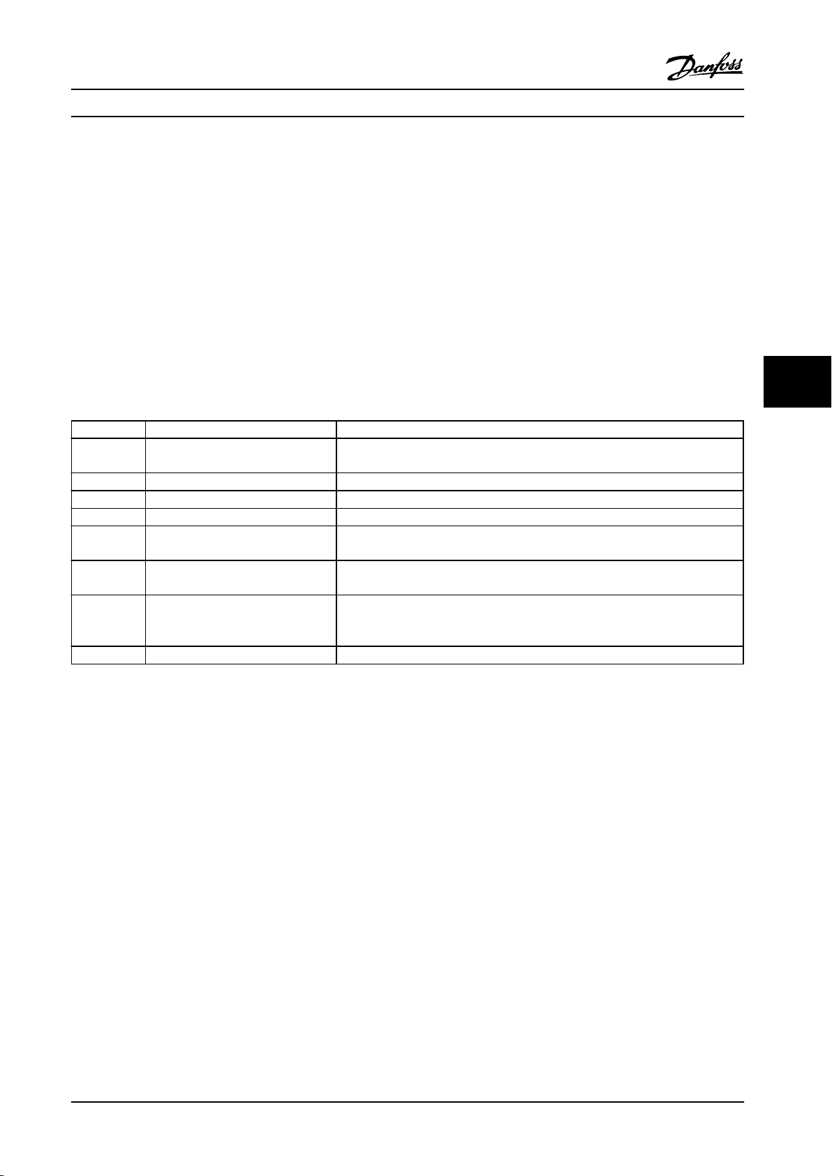
Programming Instruction Manual
6.2 How to Program the Active Filter
The factory settings for the filter part of the Low Harmonic Drive are selected for optimal operation with a minimum of
additional programming. All CT values, as well as frequency, voltage levels and other values directly linked to the adjustable
frequency drive configuration are pre-set.
Do not change any other parameters influencing the filter operation. However, selection of readouts and information
displayed on the LCP status lines can be customized.
To set up the filter, two steps are necessary:
1.
Change the nominal voltage in 300-10 Active Filter Nominal Voltage
2. Make sure the filter is in auto mode (press [Auto On])
Overview of parameter groups for the filter part
Group Title Function
0-** Operation/Display Parameters related to the fundamental functions of the filter, function of the LCP
buttons and configuration of the LCP display.
5-** Digital In/Out Parameter group for configuring the digital inputs and outputs.
8-** Communication and Options Parameter group for configuring communications and options.
14-** Special Functions Parameter group for configuring special functions.
15-** Unit Information Parameter group containing active filter information such as operating data,
hardware configuration and software versions.
16-** Data Readouts Parameter group for data readouts, such as current references, voltages, control,
alarm, warning and status words.
300-** AF Settings
301-** AF Readouts Parameter group for the filter readouts.
Table 6.10 Parameter Groups
A list of all parameters accessible from the filter LCP can be found in the section Parameter Options - Filter. A more detailed
description of the active filter parameters can be found in chapter 6.4 Parameter Lists - Active Filter.
Using the Low Harmonic Drive in NPN Mode
6.2.1
Parameter group for setting the active filter. Apart from par. 300-10, Active Filter
Nominal Voltage, it is not recommended to change the settings of this parameter
group.
6 6
The default setting for parameter 5-00 Digital I/O Mode is PNP mode. If NPN mode is desired, it is necessary to change the
wiring in the filter part of the Low Harmonic Drive. Before changing the setting in parameter 5-00 Digital I/O Mode to NPN
mode, the wire connected to 24 V (control terminal 12 or 13) must be changed to terminal 20 (ground).
MG37A222 Danfoss A/S © Rev. 2014-02-07 All rights reserved. 77
Page 80
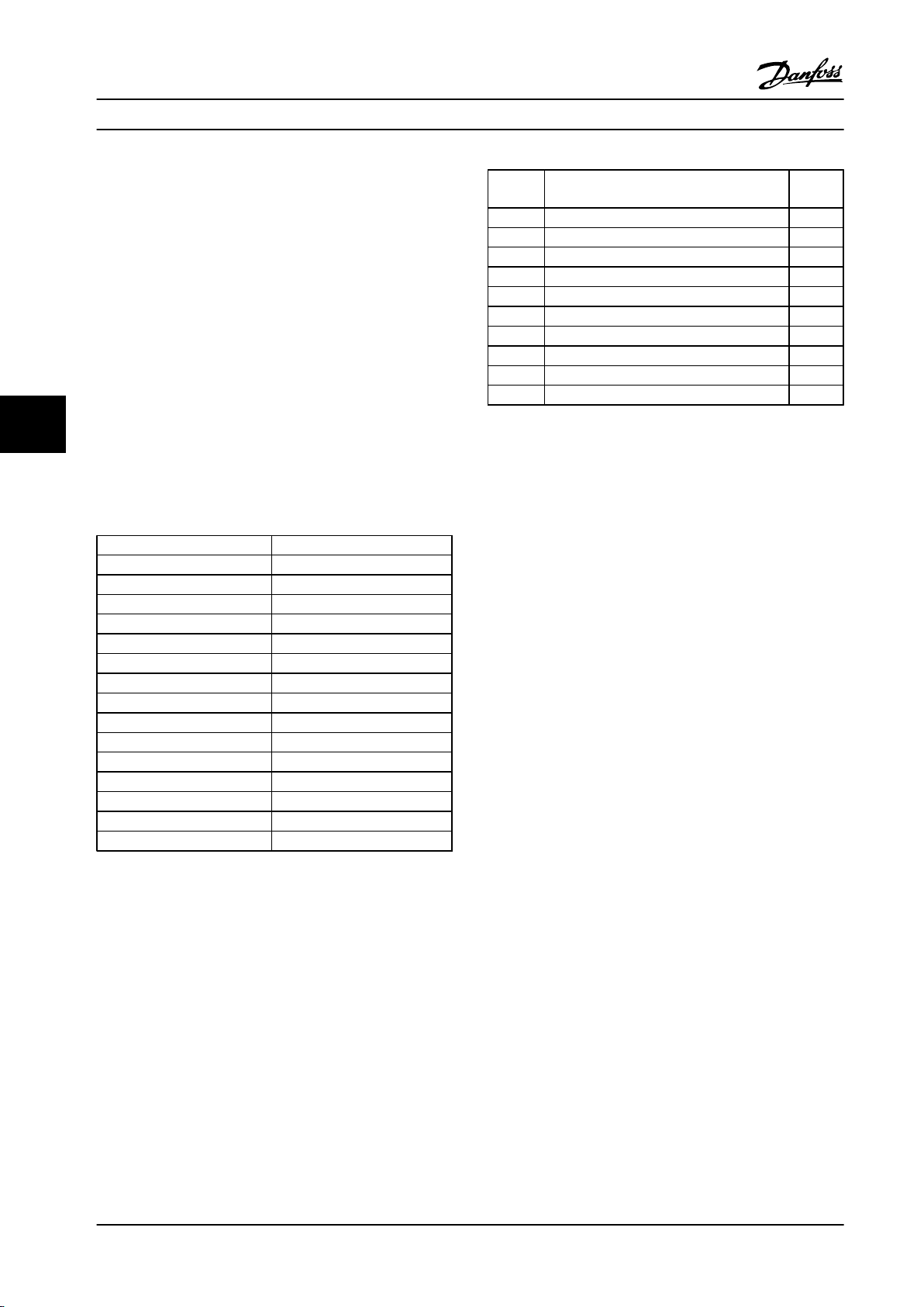
Programming
Instruction Manual
6.3 Parameter Lists - Adjustable Frequency
Drive
Changes during operation
True means that the parameter can be changed while the
adjustable frequency drive is in operation and false means
that it must be stopped before making a change.
4-Set-up
'All set-up': the parameters can be set individually in each
of the four set-ups, i.e., one single parameter can have four
different data values.
Data
type
2 Integer 8 Int8
3 Integer 16 Int16
4 Integer 32 Int32
5 Unsigned 8 Uint8
6 Unsigned 16 Uint16
7 Unsigned 32 Uint32
9 Visible String VisStr
33 Normalized value 2 bytes N2
35 Bit sequence of 16 Boolean variables V2
54 Time difference w/o date TimD
Description Type
’1 set-up’: data value is the same in all set-ups.
66
Table 6.12 Data Types
Conversion index
This number refers to a conversion figure used when
writing or reading to and from the adjustable frequency
See the adjustable frequency drive Design Guide for further
information about data types 33, 35 and 54.
drive.
Parameter Selection
6.3.1
Conv. index Conv. factor
100 1
67 1/60
6 1000000
5 100000
4 10000
3 1000
2 100
1 10
0 1
-1 0.1
-2 0.01
-3 0.001
-4 0.0001
-5 0.00001
-6 0.000001
Parameters for the adjustable frequency drive are grouped
into various parameter groups for easy selection of the
correct parameters for optimized operation of the
adjustable frequency drive.
0-** Operation and display parameters for basic adjustable
frequency drive settings
1-** Load and motor parameters, includes all load and
motor related parameters
2-** Brake parameters
3-** References and ramping parameters, includes DigiPot
function
Table 6.11 Conversion Index
4-** Limits/Warnings, setting of limits and warning
parameters
5-** Digital inputs and outputs, includes relay controls
6-** Analog inputs and outputs
7-** Controllers, setting parameters for speed and process
controls
8-** Communication and option parameters, setting of FC
RS-485 and FC USB port parameters.
9-** Profibus parameters
78 Danfoss A/S © Rev. 2014-02-07 All rights reserved. MG37A222
Page 81

Programming Instruction Manual
10-** DeviceNet and CAN Fieldbus parameters
12-** Ethernet parameters
13-** Smart Logic Control parameters
14-** Special Function parameters
15-** Drive Information parameters
16-** Data Readout parameters
17-** Encoder option parameters
18-** Data Readouts 2
30-** Special Features
32-** MCO 305 basic parameters
33-** MCO 305 advanced parameters
34-** MCO data readout parameters
35-** Sensor Input Option
6 6
MG37A222 Danfoss A/S © Rev. 2014-02-07 All rights reserved. 79
Page 82

Programming Instruction Manual
6.3.2 0-** Operation/Display
Par.
Parameter description Default value 4-set-up Change
No. #
0-0* Basic Settings
0-01 Language [0] English 1 set-up TRUE - Uint8
0-02 Motor Speed Unit [0] RPM 2 set-ups FALSE - Uint8
0-03 Regional Settings [0] International 2 set-ups FALSE - Uint8
0-04 Operating State at Power-up (Hand) [1] Forced stop, ref=old All set-ups TRUE - Uint8
0-09 Performance Monitor 0 % All set-ups TRUE -1 Uint16
0-1* Set-up Operations
0-10 Active Set-up [1] Set-up 1 1 set-up TRUE - Uint8
0-11 Edit Set-up [1] Set-up 1 All set-ups TRUE - Uint8
0-12 This Set-up Linked to [0] Not linked All set-ups FALSE - Uint8
66
0-13 Readout: Linked Set-ups 0 N/A All set-ups FALSE 0 Uint16
0-14 Readout: Edit Set-ups / Channel 0 N/A All set-ups TRUE 0 Int32
0-15 Readout: actual setup 0 N/A All set-ups FALSE 0 Uint8
0-2* LCP Display
0-20 Display Line 1.1 Small 1617 All set-ups TRUE - Uint16
0-21 Display Line 1.2 Small 1614 All set-ups TRUE - Uint16
0-22 Display Line 1.3 Small 1610 All set-ups TRUE - Uint16
0-23 Display Line 2 Large 1613 All set-ups TRUE - Uint16
0-24 Display Line 3 Large 1602 All set-ups TRUE - Uint16
0-25 My Personal Menu ExpressionLimit 1 set-up TRUE 0 Uint16
0-3* LCP Cust. Readout
0-30 Unit for User-defined Readout [0] None All set-ups TRUE - Uint8
0-31 Min Value of User-defined Readout 0 CustomReadoutUnit All set-ups TRUE -2 Int32
0-32 Max Value of User-defined Readout 100 CustomReadoutUnit All set-ups TRUE -2 Int32
0-37 Display Text 1 0 N/A 1 set-up TRUE 0 VisStr[25]
0-38 Display Text 2 0 N/A 1 set-up TRUE 0 VisStr[25]
0-39 Display Text 3 0 N/A 1 set-up TRUE 0 VisStr[25]
0-4* LCP Keypad
0-40 [Hand on] Key on LCP ExpressionLimit All set-ups TRUE - Uint8
0-41 [Off] Key on LCP ExpressionLimit All set-ups TRUE - Uint8
0-42 [Auto on] Key on LCP ExpressionLimit All set-ups TRUE - Uint8
0-43 [Reset] Key on LCP ExpressionLimit All set-ups TRUE - Uint8
0-44 [Off/Reset] Key on LCP ExpressionLimit All set-ups TRUE - Uint8
0-45 [Drive Bypass] Key on LCP ExpressionLimit All set-ups TRUE - Uint8
0-5* Copy/Save
0-50 LCP Copy [0] No copy All set-ups FALSE - Uint8
0-51 Set-up Copy [0] No copy All set-ups FALSE - Uint8
0-6* Password
0-60 Main Menu Password 100 N/A 1 set-up TRUE 0 Int16
0-61 Access to Main Menu w/o Password [0] Full access 1 set-up TRUE - Uint8
0-65 Quick Menu Password 200 N/A 1 set-up TRUE 0 Int16
0-66 Access to Quick Menu w/o Password [0] Full access 1 set-up TRUE - Uint8
0-67 Bus Password Access 0 N/A All set-ups TRUE 0 Uint16
0-68 Safety Parameters Password 300 N/A 1 set-up TRUE 0 Uint16
0-69 Password Protection of Safety Parameters [0] Disabled 1 set-up TRUE - Uint8
during
operation
Conver-
sion
index
Type
80 Danfoss A/S © Rev. 2014-02-07 All rights reserved. MG37A222
Page 83

Programming Instruction Manual
6.3.3 1-** Load/Motor
Par.
Parameter description Default value 4-set-up FC 302
No. #
1-0* General Settings
1-00 Configuration Mode ExpressionLimit All set-ups TRUE - Uint8
1-01 Motor Control Principle ExpressionLimit All set-ups FALSE - Uint8
1-02 Flux Motor Feedback Source [1] 24V encoder All set-ups x FALSE - Uint8
1-03 Torque Characteristics [0] Constant torque All set-ups TRUE - Uint8
1-04 Overload Mode [0] High torque All set-ups FALSE - Uint8
1-05 Local Mode Configuration [2] As mode par 1-00 All set-ups TRUE - Uint8
1-06 Clockwise Direction [0] Normal All set-ups FALSE - Uint8
1-07 Motor Angle Offset Adjust [0] Manual All set-ups x FALSE - Uint8
1-1* Special Settings
1-10 Motor Construction [0] Asynchron All set-ups FALSE - Uint8
1-11 Motor Model ExpressionLimit All set-ups x FALSE - Uint8
1-14 Damping Gain 140 % All set-ups TRUE 0 Int16
1-15 Low Speed Filter Time Const. ExpressionLimit All set-ups TRUE -2 Uint16
1-16 High Speed Filter Time Const. ExpressionLimit All set-ups TRUE -2 Uint16
1-17 Voltage filter time const. ExpressionLimit All set-ups TRUE -3 Uint16
1-18 Min. Current at No Load 0 % All set-ups TRUE 0 Uint16
1-2* Motor Data
1-20 Motor Power [kW] ExpressionLimit All set-ups FALSE 1 Uint32
1-21 Motor Power [HP] ExpressionLimit All set-ups FALSE -2 Uint32
1-22 Motor Voltage ExpressionLimit All set-ups FALSE 0 Uint16
1-23 Motor Frequency ExpressionLimit All set-ups FALSE 0 Uint16
1-24 Motor Current ExpressionLimit All set-ups FALSE -2 Uint32
1-25 Motor Nominal Speed ExpressionLimit All set-ups FALSE 67 Uint16
1-26 Motor Cont. Rated Torque ExpressionLimit All set-ups FALSE -1 Uint32
1-29 Automatic Motor Adaptation (AMA) [0] Off All set-ups FALSE - Uint8
1-3* Addl. Motor Data
1-30 Stator Resistance (Rs) ExpressionLimit All set-ups FALSE -4 Uint32
1-31 Rotor Resistance (Rr) ExpressionLimit All set-ups FALSE -4 Uint32
1-33 Stator Leakage Reactance (X1) ExpressionLimit All set-ups FALSE -4 Uint32
1-34 Rotor Leakage Reactance (X2) ExpressionLimit All set-ups FALSE -4 Uint32
1-35 Main Reactance (Xh) ExpressionLimit All set-ups FALSE -4 Uint32
1-36 Iron Loss Resistance (Rfe) ExpressionLimit All set-ups FALSE -3 Uint32
1-37 d-axis Inductance (Ld) ExpressionLimit All set-ups x FALSE -4 Int32
1-38 q-axis Inductance (Lq) ExpressionLimit All set-ups x FALSE -6 Int32
1-39 Motor Poles ExpressionLimit All set-ups FALSE 0 Uint8
1-40 Back EMF at 1000 RPM ExpressionLimit All set-ups x FALSE 0 Uint16
1-41 Motor Angle Offset 0 N/A All set-ups FALSE 0 Int16
1-44 d-axis Inductance Sat. (LdSat) ExpressionLimit All set-ups x FALSE -4 Int32
1-45 q-axis Inductance Sat. (LqSat) ExpressionLimit All set-ups x FALSE -4 Int32
1-46 Position Detection Gain 100 % All set-ups TRUE 0 Uint16
1-47 Torque Calibration ExpressionLimit All set-ups TRUE - Uint8
1-48 Inductance Sat. Point 35 % All set-ups x TRUE 0 Int16
1-5* Load-Indep. Setting
1-50 Motor Magnetization at Zero Speed 100 % All set-ups TRUE 0 Uint16
1-51 Min Speed Normal Magnetizing [RPM] ExpressionLimit All set-ups TRUE 67 Uint16
1-52 Min Speed Normal Magnetizing [Hz] ExpressionLimit All set-ups TRUE -1 Uint16
1-53 Model Shift Frequency ExpressionLimit All set-ups x FALSE -1 Uint16
1-54 Voltage reduction in fieldweakening 0 V All set-ups FALSE 0 Uint8
1-55 U/f Characteristic - U ExpressionLimit All set-ups TRUE -1 Uint16
1-56 U/f Characteristic - F ExpressionLimit All set-ups TRUE -1 Uint16
1-58 Flystart Test Pulses Current ExpressionLimit All set-ups FALSE 0 Uint16
1-59 Flystart Test Pulses Frequency ExpressionLimit All set-ups FALSE 0 Uint16
1-6* Load-Depend. Settg.
1-60 Low Speed Load Compensation 100 % All set-ups TRUE 0 Int16
1-61 High Speed Load Compensation 100 % All set-ups TRUE 0 Int16
1-62 Slip Compensation ExpressionLimit All set-ups TRUE 0 Int16
1-63 Slip Compensation Time Constant ExpressionLimit All set-ups TRUE -2 Uint16
only
Change
during
operation
Conver-
sion index
Type
6 6
MG37A222 Danfoss A/S © Rev. 2014-02-07 All rights reserved. 81
Page 84

Programming Instruction Manual
Par.
Parameter description Default value 4-set-up FC 302
No. #
1-64 Resonance Damping 100 % All set-ups TRUE 0 Uint16
1-65 Resonance Damping Time Constant 5 ms All set-ups TRUE -3 Uint8
1-66 Min. Current at Low Speed ExpressionLimit All set-ups x TRUE 0 Uint32
1-67 Load Type [0] Passive load All set-ups x TRUE - Uint8
1-68 Minimum Inertia ExpressionLimit All set-ups x FALSE -4 Uint32
1-69 Maximum Inertia ExpressionLimit All set-ups x FALSE -4 Uint32
1-7* Start Adjustments
1-70 PM Start Mode [0] Rotor Detection All set-ups TRUE - Uint8
1-71 Start Delay 0 s All set-ups TRUE -1 Uint8
1-72 Start Function [2] Coast/delay time All set-ups TRUE - Uint8
1-73 Flying Start ExpressionLimit All set-ups FALSE - Uint8
1-74 Start Speed [RPM] ExpressionLimit All set-ups TRUE 67 Uint16
1-75 Start Speed [Hz] ExpressionLimit All set-ups TRUE -1 Uint16
66
1-76 Start Current 0 A All set-ups TRUE -2 Uint32
1-8* Stop Adjustments
1-80 Function at Stop [0] Coast All set-ups TRUE - Uint8
1-81 Min Speed for Function at Stop [RPM] ExpressionLimit All set-ups TRUE 67 Uint16
1-82 Min Speed for Function at Stop [Hz] ExpressionLimit All set-ups TRUE -1 Uint16
1-83 Precise Stop Function [0] Precise ramp stop All set-ups FALSE - Uint8
1-84 Precise Stop Counter Value 100000 N/A All set-ups TRUE 0 Uint32
1-85 Precise Stop Speed Compensation Delay 10 ms All set-ups TRUE -3 Uint8
1-9* Motor Temperature
1-90 Motor Thermal Protection ExpressionLimit All set-ups TRUE - Uint8
1-91 Motor External Fan ExpressionLimit All set-ups TRUE - Uint16
1-93 Thermistor Resource [0] None All set-ups TRUE - Uint8
1-94 ATEX ETR cur.lim. speed reduction 0 % 2 set-ups x TRUE -1 Uint16
1-95 KTY Sensor Type [0] KTY Sensor 1 All set-ups x TRUE - Uint8
1-96 KTY Thermistor Resource [0] None All set-ups x TRUE - Uint8
1-97 KTY Threshold level 80 °C 1 set-up x TRUE 100 Int16
1-98 ATEX ETR interpol. points freq. ExpressionLimit 1 set-up x TRUE -1 Uint16
1-99 ATEX ETR interpol points current ExpressionLimit 2 set-ups x TRUE 0 Uint16
only
Change
during
operation
Conver-
sion index
Type
82 Danfoss A/S © Rev. 2014-02-07 All rights reserved. MG37A222
Page 85

Programming Instruction Manual
6.3.4 2-** Brakes
Par.
Parameter description Default value 4-set-up Change
No. #
2-0* DC Brake
2-00 DC Hold Current 50 % All set-ups TRUE 0 Uint8
2-01 DC Brake Current 50 % All set-ups TRUE 0 Uint16
2-02 DC Braking Time 10 s All set-ups TRUE -1 Uint16
2-03 DC Brake Cut-in Speed [RPM] ExpressionLimit All set-ups TRUE 67 Uint16
2-04 DC Brake Cut-in Speed [Hz] ExpressionLimit All set-ups TRUE -1 Uint16
2-05 Maximum Reference MaxReference (P303) All set-ups TRUE -3 Int32
2-06 Parking Current 50 % All set-ups TRUE 0 Uint16
2-07 Parking Time 3 s All set-ups TRUE -1 Uint16
2-1* Brake Energy Funct.
2-10 Brake Function ExpressionLimit All set-ups TRUE - Uint8
2-11 Brake Resistor (ohm) ExpressionLimit All set-ups TRUE 0 Uint16
2-12 Brake Power Limit (kW) ExpressionLimit All set-ups TRUE 0 Uint32
2-13 Brake Power Monitoring [0] Off All set-ups TRUE - Uint8
2-15 Brake Check [0] Off All set-ups TRUE - Uint8
2-16 AC Brake Max. Current 100 % All set-ups TRUE -1 Uint32
2-17 Over-voltage Control [0] Disabled All set-ups TRUE - Uint8
2-18 Brake Check Condition [0] At Power-up All set-ups TRUE - Uint8
2-19 Over-voltage Gain 100 % All set-ups TRUE 0 Uint16
2-2* Mechanical Brake
2-20 Release Brake Current ImaxVLT (P1637) All set-ups TRUE -2 Uint32
2-21 Activate Brake Speed [RPM] ExpressionLimit All set-ups TRUE 67 Uint16
2-22 Activate Brake Speed [Hz] ExpressionLimit All set-ups TRUE -1 Uint16
2-23 Activate Brake Delay 0 s All set-ups TRUE -1 Uint8
2-24 Stop Delay 0 s All set-ups TRUE -1 Uint8
2-25 Brake Release Time 0.20 s All set-ups TRUE -2 Uint16
2-26 Torque Ref 0 % All set-ups TRUE -2 Int16
2-27 Torque Ramp Up Time 0.2 s All set-ups TRUE -1 Uint8
2-28 Gain Boost Factor 1 N/A All set-ups TRUE -2 Uint16
2-29 Torque Ramp Down Time 0 s All set-ups TRUE -1 Uint8
2-3* Adv. Mech Brake
2-30 Position P Start Proportional Gain 0.0000 N/A All set-ups TRUE -4 Uint32
2-31 Speed PID Start Proportional Gain 0.0150 N/A All set-ups TRUE -4 Uint32
2-32 Speed PID Start Integral Time 200.0 ms All set-ups TRUE -4 Uint32
2-33 Speed PID Start Lowpass Filter Time 10.0 ms All set-ups TRUE -4 Uint16
during
operation
Conver-
sion index
Type
6 6
MG37A222 Danfoss A/S © Rev. 2014-02-07 All rights reserved. 83
Page 86

Programming Instruction Manual
6.3.5 3-** Reference/Ramps
Par.
Parameter description Default value 4-set-up Change
No. #
3-0* Reference Limits
3-00 Reference Range ExpressionLimit All set-ups TRUE - Uint8
3-01 Reference/Feedback Unit ExpressionLimit All set-ups TRUE - Uint8
3-02 Minimum Reference ExpressionLimit All set-ups TRUE -3 Int32
3-03 Maximum Reference ExpressionLimit All set-ups TRUE -3 Int32
3-04 Reference Function [0] Sum All set-ups TRUE - Uint8
3-1* References
3-10 Preset Reference 0 % All set-ups TRUE -2 Int16
3-11 Jog Speed [Hz] ExpressionLimit All set-ups TRUE -1 Uint16
3-12 Catch up/slow-down value 0 % All set-ups TRUE -2 Int16
66
3-13 Reference Site [0] Linked to Hand / Auto All set-ups TRUE - Uint8
3-14 Preset Relative Reference 0 % All set-ups TRUE -2 Int32
3-15 Reference Resource 1 ExpressionLimit All set-ups TRUE - Uint8
3-16 Reference Resource 2 ExpressionLimit All set-ups TRUE - Uint8
3-17 Reference Resource 3 ExpressionLimit All set-ups TRUE - Uint8
3-18 Relative Scaling Reference Resource [0] No function All set-ups TRUE - Uint8
3-19 Jog Speed [RPM] ExpressionLimit All set-ups TRUE 67 Uint16
3-4* Ramp 1
3-40 Ramp 1 Type [0] Linear All set-ups TRUE - Uint8
3-41 Ramp 1 Ramp-up Time ExpressionLimit All set-ups TRUE -2 Uint32
3-42 Ramp 1 Ramp-down Time ExpressionLimit All set-ups TRUE -2 Uint32
3-45 Ramp 1 S-ramp Ratio at Accel. Start 50 % All set-ups TRUE 0 Uint8
3-46 Ramp 1 S-ramp Ratio at Accel. End 50 % All set-ups TRUE 0 Uint8
3-47 Ramp 1 S-ramp Ratio at Decel. Start 50 % All set-ups TRUE 0 Uint8
3-48 Ramp 1 S-ramp Ratio at Decel. End 50 % All set-ups TRUE 0 Uint8
3-5* Ramp 2
3-50 Ramp 2 Type [0] Linear All set-ups TRUE - Uint8
3-51 Ramp 2 Ramp-up Time ExpressionLimit All set-ups TRUE -2 Uint32
3-52 Ramp 2 Ramp-down Time ExpressionLimit All set-ups TRUE -2 Uint32
3-55 Ramp 2 S-ramp Ratio at Accel. Start 50 % All set-ups TRUE 0 Uint8
3-56 Ramp 2 S-ramp Ratio at Accel. End 50 % All set-ups TRUE 0 Uint8
3-57 Ramp 2 S-ramp Ratio at Decel. Start 50 % All set-ups TRUE 0 Uint8
3-58 Ramp 2 S-ramp Ratio at Decel. End 50 % All set-ups TRUE 0 Uint8
3-6* Ramp 3
3-60 Ramp 3 Type [0] Linear All set-ups TRUE - Uint8
3-61 Ramp 3 Ramp-up Time ExpressionLimit All set-ups TRUE -2 Uint32
3-62 Ramp 3 Ramp-down Time ExpressionLimit All set-ups TRUE -2 Uint32
3-65 Ramp 3 S-ramp Ratio at Accel. Start 50 % All set-ups TRUE 0 Uint8
3-66 Ramp 3 S-ramp Ratio at Accel. End 50 % All set-ups TRUE 0 Uint8
3-67 Ramp 3 S-ramp Ratio at Decel. Start 50 % All set-ups TRUE 0 Uint8
3-68 Ramp 3 S-ramp Ratio at Decel. End 50 % All set-ups TRUE 0 Uint8
3-7* Ramp 4
3-70 Ramp 4 Type [0] Linear All set-ups TRUE - Uint8
3-71 Ramp 4 Ramp-up Time ExpressionLimit All set-ups TRUE -2 Uint32
3-72 Ramp 4 Ramp-down Time ExpressionLimit All set-ups TRUE -2 Uint32
3-75 Ramp 4 S-ramp Ratio at Accel. Start 50 % All set-ups TRUE 0 Uint8
3-76 Ramp 4 S-ramp Ratio at Accel. End 50 % All set-ups TRUE 0 Uint8
3-77 Ramp 4 S-ramp Ratio at Decel. Start 50 % All set-ups TRUE 0 Uint8
3-78 Ramp 4 S-ramp Ratio at Decel. End 50 % All set-ups TRUE 0 Uint8
3-8* Other Ramps
3-80 Jog Ramp Time ExpressionLimit All set-ups TRUE -2 Uint32
3-81 Quick Stop Ramp Time ExpressionLimit 2 set-ups TRUE -2 Uint32
3-82 Quick Stop Ramp Type [0] Linear All set-ups TRUE - Uint8
3-83 Quick Stop S-ramp Ratio at Decel. Start 50 % All set-ups TRUE 0 Uint8
3-84 Quick Stop S-ramp Ratio at Decel. End 50 % All set-ups TRUE 0 Uint8
3-9* Digital Pot. meter
3-90 Step Size 0.10 % All set-ups TRUE -2 Uint16
during
operation
Conver-
sion index
Type
84 Danfoss A/S © Rev. 2014-02-07 All rights reserved. MG37A222
Page 87

Programming Instruction Manual
Par.
Parameter description Default value 4-set-up Change
No. #
3-91 Ramp Time 1 s All set-ups TRUE -2 Uint32
3-92 Power Restore [0] Off All set-ups TRUE - Uint8
3-93 Maximum Limit 100 % All set-ups TRUE 0 Int16
3-94 Minimum Limit -100 % All set-ups TRUE 0 Int16
3-95 Ramp Delay ExpressionLimit All set-ups TRUE -3 TimD
during
operation
Conver-
sion index
Type
6 6
MG37A222 Danfoss A/S © Rev. 2014-02-07 All rights reserved. 85
Page 88

Programming Instruction Manual
6.3.6 4-** Limits/Warnings
Par.
Parameter description Default value 4-set-up Change
No. #
4-1* Motor Limits
4-10 Motor Speed Direction ExpressionLimit All set-ups FALSE - Uint8
4-11 Motor Speed Low Limit [RPM] ExpressionLimit All set-ups TRUE 67 Uint16
4-12 Motor Speed Low Limit [Hz] ExpressionLimit All set-ups TRUE -1 Uint16
4-13 Motor Speed High Limit [RPM] ExpressionLimit All set-ups TRUE 67 Uint16
4-14 Motor Speed High Limit [Hz] ExpressionLimit All set-ups TRUE -1 Uint16
4-16 Torque Limit Motor Mode ExpressionLimit All set-ups TRUE -1 Uint16
4-17 Torque Limit Generator Mode 100 % All set-ups TRUE -1 Uint16
4-18 Current Limit ExpressionLimit All set-ups TRUE -1 Uint32
4-19 Max Output Frequency ExpressionLimit All set-ups FALSE -1 Uint16
66
4-2* Limit Factors
4-20 Torque Limit Factor Source [0] No function All set-ups TRUE - Uint8
4-21 Speed Limit Factor Source [0] No function All set-ups TRUE - Uint8
4-3* Motor Speed Mon.
4-30 Motor Feedback Loss Function [2] Trip All set-ups TRUE - Uint8
4-31 Motor Feedback Speed Error 300 RPM All set-ups TRUE 67 Uint16
4-32 Motor Feedback Loss Timeout 0.05 s All set-ups TRUE -2 Uint16
4-34 Tracking Error Function ExpressionLimit All set-ups TRUE - Uint8
4-35 Tracking Error 10 RPM All set-ups TRUE 67 Uint16
4-36 Tracking Error Timeout 1 s All set-ups TRUE -2 Uint16
4-37 Tracking Error Ramping 100 RPM All set-ups TRUE 67 Uint16
4-38 Tracking Error Ramping Timeout 1 s All set-ups TRUE -2 Uint16
4-39 Tracking Error After Ramping Timeout 5 s All set-ups TRUE -2 Uint16
4-5* Adj. Warnings
4-50 Warning Current Low 0 A All set-ups TRUE -2 Uint32
4-51 Warning Current High ImaxVLT (P1637) All set-ups TRUE -2 Uint32
4-52 Warning Speed Low 0 RPM All set-ups TRUE 67 Uint16
4-53 Warning Speed High ExpressionLimit All set-ups TRUE 67 Uint16
4-54 Warning Reference Low -999999.999 N/A All set-ups TRUE -3 Int32
4-55 Warning Reference High 999999.999 N/A All set-ups TRUE -3 Int32
4-56 Warning Feedback Low
4-57 Warning Feedback High
4-58 Missing Motor Phase Function ExpressionLimit All set-ups TRUE - Uint8
4-6* Speed Bypass
4-60 Bypass Speed From [RPM] ExpressionLimit All set-ups TRUE 67 Uint16
4-61 Bypass Speed From [Hz] ExpressionLimit All set-ups TRUE -1 Uint16
4-62 Bypass Speed to [RPM] ExpressionLimit All set-ups TRUE 67 Uint16
4-63 Bypass Speed To [Hz] ExpressionLimit All set-ups TRUE -1 Uint16
-999999.999 ReferenceFeedbackUnit All set-ups TRUE -3 Int32
999999.999 ReferenceFeedbackUnit All set-ups TRUE -3 Int32
during
operation
Conver-
sion index
Type
86 Danfoss A/S © Rev. 2014-02-07 All rights reserved. MG37A222
Page 89

Programming Instruction Manual
6.3.7 5-** Digital In/Out
Par.
Parameter description Default value 4-set-up FC
No. #
5-0* Digital I/O mode
5-00 Digital I/O Mode [0] PNP All set-ups FALSE - Uint8
5-01 Terminal 27 Mode [0] Input All set-ups TRUE - Uint8
5-02 Terminal 29 Mode [0] Input All set-ups x TRUE - Uint8
5-1* Digital Inputs
5-10 Terminal 18 Digital Input ExpressionLimit All set-ups TRUE - Uint8
5-11 Terminal 19 Digital Input ExpressionLimit All set-ups TRUE - Uint8
5-12 Terminal 27 Digital Input ExpressionLimit All set-ups TRUE - Uint8
5-13 Terminal 29 Digital Input ExpressionLimit All set-ups x TRUE - Uint8
5-14 Terminal 32 Digital Input ExpressionLimit All set-ups TRUE - Uint8
5-15 Terminal 33 Digital Input ExpressionLimit All set-ups TRUE - Uint8
5-16 Terminal X30/2 Digital Input ExpressionLimit All set-ups TRUE - Uint8
5-17 Terminal X30/3 Digital Input ExpressionLimit All set-ups TRUE - Uint8
5-18 Terminal X30/4 Digital Input ExpressionLimit All set-ups TRUE - Uint8
5-19 Terminal 37 Safe Stop ExpressionLimit 1 set-up TRUE - Uint8
5-20 Terminal X46/1 Digital Input [0] No operation All set-ups TRUE - Uint8
5-21 Terminal X46/3 Digital Input [0] No operation All set-ups TRUE - Uint8
5-22 Terminal X46/5 Digital Input [0] No operation All set-ups TRUE - Uint8
5-23 Terminal X46/7 Digital Input [0] No operation All set-ups TRUE - Uint8
5-24 Terminal X46/9 Digital Input [0] No operation All set-ups TRUE - Uint8
5-25 Terminal X46/11 Digital Input [0] No operation All set-ups TRUE - Uint8
5-26 Terminal X46/13 Digital Input [0] No operation All set-ups TRUE - Uint8
5-3* Digital Outputs
5-30 Terminal 27 Digital Output ExpressionLimit All set-ups TRUE - Uint8
5-31 Terminal 29 Digital Output ExpressionLimit All set-ups x TRUE - Uint8
5-32 Term X30/6 Digi Out (MCB 101) ExpressionLimit All set-ups TRUE - Uint8
5-33 Term X30/7 Digi Out (MCB 101) ExpressionLimit All set-ups TRUE - Uint8
5-4* Relays
5-40 Function Relay ExpressionLimit All set-ups TRUE - Uint8
5-41 On Delay, Relay 0.01 s All set-ups TRUE -2 Uint16
5-42 Off Delay, Relay 0.01 s All set-ups TRUE -2 Uint16
5-5* Pulse Input
5-50 Term. 29 Low Frequency 100 Hz All set-ups x TRUE 0 Uint32
5-51 Term. 29 High Frequency 100 Hz All set-ups x TRUE 0 Uint32
5-52 Term. 29 Low Ref./Feedb. Value 0 ReferenceFeedbackUnit All set-ups x TRUE -3 Int32
5-53 Term. 29 High Ref./Feedb. Value ExpressionLimit All set-ups x TRUE -3 Int32
5-54 Pulse Filter Time Constant #29 100 ms All set-ups x FALSE -3 Uint16
5-55 Term. 33 Low Frequency 100 Hz All set-ups TRUE 0 Uint32
5-56 Term. 33 High Frequency 100 Hz All set-ups TRUE 0 Uint32
5-57 Term. 33 Low Ref./Feedb. Value 0 ReferenceFeedbackUnit All set-ups TRUE -3 Int32
5-58 Term. 33 High Ref./Feedb. Value ExpressionLimit All set-ups TRUE -3 Int32
5-59 Pulse Filter Time Constant #33 100 ms All set-ups FALSE -3 Uint16
5-6* Pulse Output
5-60 Terminal 27 Pulse Output Variable ExpressionLimit All set-ups TRUE - Uint8
5-62 Pulse Output Max Freq #27 ExpressionLimit All set-ups TRUE 0 Uint32
5-63 Terminal 29 Pulse Output Variable ExpressionLimit All set-ups x TRUE - Uint8
5-65 Pulse Output Max Freq #29 ExpressionLimit All set-ups x TRUE 0 Uint32
5-66 Terminal X30/6 Pulse Output Variable ExpressionLimit All set-ups TRUE - Uint8
5-68 Pulse Output Max Freq #X30/6 ExpressionLimit All set-ups TRUE 0 Uint32
5-7* 24V Encoder Input
5-70 Term 32/33 Pulses Per Revolution 1024 N/A All set-ups FALSE 0 Uint16
5-71 Term 32/33 Encoder Direction [0] Clockwise All set-ups FALSE - Uint8
5-8* I/O Options
5-80 AHF Cap Reconnect Delay 25 s 2 set-ups x TRUE 0 Uint16
5-9* Bus Controlled
5-90 Digital & Relay Bus Control 0 N/A All set-ups TRUE 0 Uint32
5-93 Pulse Out #27 Bus Control 0 % All set-ups TRUE -2 N2
5-94 Pulse Out #27 Timeout Preset 0 % 1 set-up TRUE -2 Uint16
302
only
Change during
operation
Conver-
sion
index
Type
6 6
MG37A222 Danfoss A/S © Rev. 2014-02-07 All rights reserved. 87
Page 90

Programming Instruction Manual
Par.
Parameter description Default value 4-set-up FC
No. #
5-95 Pulse Out #29 Bus Control 0 % All set-ups x TRUE -2 N2
5-96 Pulse Out #29 Timeout Preset 0 % 1 set-up x TRUE -2 Uint16
5-97 Pulse Out #X30/6 Bus Control 0 % All set-ups TRUE -2 N2
5-98 Pulse Out #X30/6 Timeout Preset 0 % 1 set-up TRUE -2 Uint16
302
only
Change during
operation
Conver-
sion
index
Type
66
88 Danfoss A/S © Rev. 2014-02-07 All rights reserved. MG37A222
Page 91

Programming Instruction Manual
6.3.8 6-** Analog In/Out
Par.
Parameter description Default value 4-set-up Change
No. #
6-0* Analog I/O Mode
6-00 Live Zero Timeout Time 10 s All set-ups TRUE 0 Uint8
6-01 Live Zero Timeout Function [0] Off All set-ups TRUE - Uint8
6-1* Analog Input 1
6-10 Terminal 53 Low Voltage 0.07 V All set-ups TRUE -2 Int16
6-11 Terminal 53 High Voltage 10 V All set-ups TRUE -2 Int16
6-12 Terminal 53 Low Current 0.14 mA All set-ups TRUE -5 Int16
6-13 Terminal 53 High Current 20 mA All set-ups TRUE -5 Int16
6-14 Terminal 53 Low Ref./Feedb. Value 0 ReferenceFeedbackUnit All set-ups TRUE -3 Int32
6-15 Terminal 53 High Ref./Feedb. Value ExpressionLimit All set-ups TRUE -3 Int32
6-16 Terminal 53 Filter Time Constant 0.001 s All set-ups TRUE -3 Uint16
6-2* Analog Input 2
6-20 Terminal 54 Low Voltage 0.07 V All set-ups TRUE -2 Int16
6-21 Terminal 54 High Voltage 10 V All set-ups TRUE -2 Int16
6-22 Terminal 54 Low Current 0.14 mA All set-ups TRUE -5 Int16
6-23 Terminal 54 High Current 20 mA All set-ups TRUE -5 Int16
6-24 Terminal 54 Low Ref./Feedb. Value 0 ReferenceFeedbackUnit All set-ups TRUE -3 Int32
6-25 Terminal 54 High Ref./Feedb. Value ExpressionLimit All set-ups TRUE -3 Int32
6-26 Terminal 54 Filter Time Constant 0.001 s All set-ups TRUE -3 Uint16
6-3* Analog Input 53
6-30 Terminal X30/11 Low Voltage 0.07 V All set-ups TRUE -2 Int16
6-31 Terminal X30/11 High Voltage 10 V All set-ups TRUE -2 Int16
6-34 Term. X30/11 Low Ref./Feedb. Value 0 ReferenceFeedbackUnit All set-ups TRUE -3 Int32
6-35 Term. X30/11 High Ref./Feedb. Value ExpressionLimit All set-ups TRUE -3 Int32
6-36 Term. X30/11 Filter Time Constant 0.001 s All set-ups TRUE -3 Uint16
6-4* Analog Input 4
6-40 Terminal X30/12 Low Voltage 0.07 V All set-ups TRUE -2 Int16
6-41 Terminal X30/12 High Voltage 10 V All set-ups TRUE -2 Int16
6-44 Term. X30/12 Low Ref./Feedb. Value 0 ReferenceFeedbackUnit All set-ups TRUE -3 Int32
6-45 Term. X30/12 High Ref./Feedb. Value ExpressionLimit All set-ups TRUE -3 Int32
6-46 Term. X30/12 Filter Time Constant 0.001 s All set-ups TRUE -3 Uint16
6-5* Analog Output 1
6-50 Terminal 42 Output ExpressionLimit All set-ups TRUE - Uint8
6-51 Terminal 42 Output Min Scale 0 % All set-ups TRUE -2 Int16
6-52 Terminal 42 Output Max Scale 100 % All set-ups TRUE -2 Int16
6-53 Term 42 Output Bus Ctrl 0 % All set-ups TRUE -2 N2
6-54 Terminal 42 Output Timeout Preset 0 % 1 set-up TRUE -2 Uint16
6-55 Analog Output Filter [0] Off 1 set-up TRUE - Uint8
6-6* Analog Output 2
6-60 Terminal X30/8 Output ExpressionLimit All set-ups TRUE - Uint8
6-61 Terminal X30/8 Min. Scale 0 % All set-ups TRUE -2 Int16
6-62 Terminal X30/8 Max. Scale 100 % All set-ups TRUE -2 Int16
6-63 Terminal X30/8 Bus Control 0 % All set-ups TRUE -2 N2
6-64 Terminal X30/8 Output Timeout Preset 0 % 1 set-up TRUE -2 Uint16
6-7* Analog Output 3
6-70 Terminal X45/1 Output ExpressionLimit All set-ups TRUE - Uint8
6-71 Terminal X45/1 Min. Scale 0 % All set-ups TRUE -2 Int16
6-72 Terminal X45/1 Max. Scale 100 % All set-ups TRUE -2 Int16
6-73 Terminal X45/1 Bus Control 0 % All set-ups TRUE -2 N2
6-74 Terminal X45/1 Output Timeout Preset 0 % 1 set-up TRUE -2 Uint16
6-8* Analog Output 4
6-80 Terminal X45/3 Output ExpressionLimit All set-ups TRUE - Uint8
6-81 Terminal X45/3 Min. Scale 0 % All set-ups TRUE -2 Int16
6-82 Terminal X45/3 Max. Scale 100 % All set-ups TRUE -2 Int16
6-83 Terminal X45/3 Bus Control 0 % All set-ups TRUE -2 N2
6-84 Terminal X45/3 Output Timeout Preset 0 % 1 set-up TRUE -2 Uint16
during
operation
Conver-
sion index
Type
6 6
MG37A222 Danfoss A/S © Rev. 2014-02-07 All rights reserved. 89
Page 92

Programming Instruction Manual
6.3.9 7-** Controllers
Par.
Parameter description Default value 4-set-up FC 302
No. #
7-0* Speed PID Ctrl.
7-00 Speed PID Feedback Source ExpressionLimit All set-ups FALSE - Uint8
7-02 Speed PID Proportional Gain ExpressionLimit All set-ups TRUE -3 Uint16
7-03 Speed PID Integral Time ExpressionLimit All set-ups TRUE -4 Uint32
7-04 Speed PID Differentiation Time ExpressionLimit All set-ups TRUE -4 Uint16
7-05 Speed PID Diff. Gain Limit 5 N/A All set-ups TRUE -1 Uint16
7-06 Speed PID Lowpass Filter Time ExpressionLimit All set-ups TRUE -4 Uint16
7-07 Speed PID Feedback Gear Ratio 1 N/A All set-ups FALSE -4 Uint32
7-08 Speed PID Feed Forward Factor 0 % All set-ups FALSE 0 Uint16
7-09 Speed PID Error Correction w/ Ramp 300 RPM All set-ups TRUE 67 Uint32
66
7-1* Torque PI Ctrl.
7-12 Torque PI Proportional Gain 100 % All set-ups TRUE 0 Uint16
7-13 Torque PI Integration Time 0.020 s All set-ups TRUE -3 Uint16
7-19 Current Controller Rise Time ExpressionLimit All set-ups TRUE 0 Uint16
7-2* Process Ctrl. Feedb
7-20 Process CL Feedback 1 Resource [0] No function All set-ups TRUE - Uint8
7-22 Process CL Feedback 2 Resource [0] No function All set-ups TRUE - Uint8
7-3* Process PID Ctrl.
7-30 Process PID Normal/Inverse Control [0] Normal All set-ups TRUE - Uint8
7-31 Process PID Anti Windup [1] On All set-ups TRUE - Uint8
7-32 Process PID Controller Start Value 0 RPM All set-ups TRUE 67 Uint16
7-33 Process PID Proportional Gain 0.01 N/A All set-ups TRUE -2 Uint16
7-34 Process PID Integral Time 10000 s All set-ups TRUE -2 Uint32
7-35 Process PID Differentiation Time 0 s All set-ups TRUE -2 Uint16
7-36 Process PID Differentiation Gain Limit 5 N/A All set-ups TRUE -1 Uint16
7-38 Process PID Feed Forward Factor 0 % All set-ups TRUE 0 Uint16
7-39 On Reference Bandwidth 5 % All set-ups TRUE 0 Uint8
7-4* Adv. Process PID I
7-40 Process PID I-part Reset [0] No All set-ups TRUE - Uint8
7-41 Process PID Output Neg. Clamp -100 % All set-ups TRUE 0 Int16
7-42 Process PID Output Pos. Clamp 100 % All set-ups TRUE 0 Int16
7-43 Process PID Gain Scale at Min. Ref. 100 % All set-ups TRUE 0 Int16
7-44 Process PID Gain Scale at Max. Ref. 100 % All set-ups TRUE 0 Int16
7-45 Process PID Feed Fwd Resource [0] No function All set-ups TRUE - Uint8
7-46 Process PID Feed Fwd Normal/ Inv. Ctrl. [0] Normal All set-ups TRUE - Uint8
7-48 PCD Feed Forward 0 N/A All set-ups x TRUE 0 Uint16
7-49 Process PID Output Normal/ Inv. Ctrl. [0] Normal All set-ups TRUE - Uint8
7-5* Adv. Process PID II
7-50 Process PID Extended PID [1] Enabled All set-ups TRUE - Uint8
7-51 Process PID Feed Fwd Gain 1 N/A All set-ups TRUE -2 Uint16
7-52 Process PID Feed Fwd Ramp-up 0.01 s All set-ups TRUE -2 Uint32
7-53 Process PID Feed Fwd Ramp-down 0.01 s All set-ups TRUE -2 Uint32
7-56 Process PID Ref. Filter Time 0.001 s All set-ups TRUE -3 Uint16
7-57 Process PID Fb. Filter Time 0.001 s All set-ups TRUE -3 Uint16
only
Change
during
operation
Conver-
sion
index
Type
90 Danfoss A/S © Rev. 2014-02-07 All rights reserved. MG37A222
Page 93
Programming Instruction Manual
6.3.10 8-** Comm. and Options
Par.
Parameter description Default value 4-set-up Change
No. #
8-0* General Settings
8-01 Control Site [0] Digital and ctrl.word All set-ups TRUE - Uint8
8-02 Control Word Source ExpressionLimit All set-ups TRUE - Uint8
8-03 Control Word Timeout Time 1 s 1 set-up TRUE -1 Uint32
8-04 Control Word Timeout Function ExpressionLimit 1 set-up TRUE - Uint8
8-05 End-of-Timeout Function [1] Resume set-up 1 set-up TRUE - Uint8
8-06 Reset Control Word Timeout [0] Do not reset All set-ups TRUE - Uint8
8-07 Diagnosis Trigger [0] Disable 2 set-ups TRUE - Uint8
8-08 Readout Filtering ExpressionLimit All set-ups TRUE - Uint8
8-1* Ctrl. Word Settings
8-10 Control Word Profile [0] FC profile All set-ups TRUE - Uint8
8-13 Configurable Status Word STW ExpressionLimit All set-ups TRUE - Uint8
8-14 Configurable Control Word CTW [1] Profile default All set-ups TRUE - Uint8
8-19 Product Code ExpressionLimit 1 set-up TRUE 0 Uint32
8-3* FC Port Settings
8-30 Protocol [0] FC 1 set-up TRUE - Uint8
8-31 Address 1 N/A 1 set-up TRUE 0 Uint8
8-32 FC Port Baud Rate ExpressionLimit 1 set-up TRUE - Uint8
8-33 Parity / Stop Bits [0] Even Parity, 1 Stop Bit 1 set-up TRUE - Uint8
8-34 Estimated cycle time 0 ms 2 set-ups TRUE -3 Uint32
8-35 Minimum Response Delay 10 ms 1 set-up TRUE -3 Uint16
8-36 Max Response Delay ExpressionLimit 1 set-up TRUE -3 Uint16
8-37 Max Inter-Char Delay ExpressionLimit 1 set-up TRUE -5 Uint16
8-4* FC MC protocol set
8-40 Telegram selection [1] Standard telegram 1 2 set-ups TRUE - Uint8
8-41 Parameters for Signals 0 All set-ups FALSE - Uint16
8-42 PCD Write Configuration ExpressionLimit 2 set-ups TRUE 0 Uint16
8-43 PCD Read Configuration ExpressionLimit 2 set-ups TRUE 0 Uint16
8-45 BTM Transaction Command [0] Off All set-ups FALSE - Uint8
8-46 BTM Transaction Status [0] Off All set-ups TRUE - Uint8
8-47 BTM Timeout 60 s 1 set-up FALSE 0 Uint16
8-48 BTM Maximum Errors 21 N/A 1 set-up TRUE 0 Uint8
8-49 BTM Error Log 0.255 N/A All set-ups TRUE -3 Uint32
8-5* Digital/Bus
8-50 Coasting Select [3] Logic OR All set-ups TRUE - Uint8
8-51 Quick Stop Select [3] Logic OR All set-ups TRUE - Uint8
8-52 DC Brake Select ExpressionLimit All set-ups TRUE - Uint8
8-53 Start Select [3] Logic OR All set-ups TRUE - Uint8
8-54 Reverse Select [3] Logic OR All set-ups TRUE - Uint8
8-55 Set-up Select [3] Logic OR All set-ups TRUE - Uint8
8-56 Preset Reference Select [3] Logic OR All set-ups TRUE - Uint8
8-57 Profidrive OFF2 Select [3] Logic OR All set-ups TRUE - Uint8
8-58 Profidrive OFF3 Select [3] Logic OR All set-ups TRUE - Uint8
8-8* AFD Port Diagnostics
8-80 Bus Message Count 0 N/A All set-ups TRUE 0 Uint32
8-81 Bus Error Count 0 N/A All set-ups TRUE 0 Uint32
8-82 Slave Messages Rcvd 0 N/A All set-ups TRUE 0 Uint32
8-83 Slave Error Count 0 N/A All set-ups TRUE 0 Uint32
8-9* Bus Jog
8-90 Bus Jog 1 Speed 100 RPM All set-ups TRUE 67 Uint16
8-91 Bus Jog 2 Speed ExpressionLimit All set-ups TRUE 67 Uint16
during
operation
Conver-
sion
index
Type
6 6
MG37A222 Danfoss A/S © Rev. 2014-02-07 All rights reserved. 91
Page 94

Programming Instruction Manual
6.3.11 9-** Profibus
Par.
Parameter description Default value 4-set-up Change
No. #
9-00 Setpoint 0 N/A All set-ups TRUE 0 Uint16
9-07 Actual Value 0 N/A All set-ups FALSE 0 Uint16
9-15 PCD Write Configuration ExpressionLimit 1 set-up TRUE - Uint16
9-16 PCD Read Configuration ExpressionLimit 2 set-ups TRUE - Uint16
9-18 Node Address 126 N/A 1 set-up TRUE 0 Uint8
9-19 Drive Unit System Number 1034 N/A All set-ups TRUE 0 Uint16
9-22 Telegram Selection [100] None 1 set-up TRUE - Uint8
9-23 Parameters for Signals 0 All set-ups TRUE - Uint16
9-27 Parameter Edit [1] Enabled 2 set-ups FALSE - Uint16
9-28 Process Control [1] Enable cyclic master 2 set-ups FALSE - Uint8
66
9-44 Fault Message Counter 0 N/A All set-ups TRUE 0 Uint16
9-45 Fault Code 0 N/A All set-ups TRUE 0 Uint16
9-47 Fault Number 0 N/A All set-ups TRUE 0 Uint16
9-52 Fault Situation Counter 0 N/A All set-ups TRUE 0 Uint16
9-53 Profibus Warning Word 0 N/A All set-ups TRUE 0 V2
9-63 Actual Baud Rate [255] No Baud rate found All set-ups TRUE - Uint8
9-64 Device Identification 0 N/A All set-ups TRUE 0 Uint16
9-65 Profile Number 0 N/A All set-ups TRUE 0
9-67 Control Word 1 0 N/A All set-ups TRUE 0 V2
9-68 Status Word 1 0 N/A All set-ups TRUE 0 V2
9-70 Edit Set-up [1] Set-up 1 All set-ups TRUE - Uint8
9-71 Profibus Save Data Values [0] Off All set-ups TRUE - Uint8
9-72 ProfibusDriveReset [0] No action 1 set-up FALSE - Uint8
9-75 DO Identification 0 N/A All set-ups TRUE 0 Uint16
9-80 Defined Parameters (1) 0 N/A All set-ups FALSE 0 Uint16
9-81 Defined Parameters (2) 0 N/A All set-ups FALSE 0 Uint16
9-82 Defined Parameters (3) 0 N/A All set-ups FALSE 0 Uint16
9-83 Defined Parameters (4) 0 N/A All set-ups FALSE 0 Uint16
9-84 Defined Parameters (5) 0 N/A All set-ups FALSE 0 Uint16
9-85 Defined Parameters (6) 0 N/A All set-ups FALSE 0 Uint16
9-90 Changed Parameters (1) 0 N/A All set-ups FALSE 0 Uint16
9-91 Changed Parameters (2) 0 N/A All set-ups FALSE 0 Uint16
9-92 Changed Parameters (3) 0 N/A All set-ups FALSE 0 Uint16
9-93 Changed parameters (4) 0 N/A All set-ups FALSE 0 Uint16
9-94 Changed parameters (5) 0 N/A All set-ups FALSE 0 Uint16
9-99 Profibus Revision Counter 0 N/A All set-ups TRUE 0 Uint16
during
operation
Conver-
sion index
Type
OctStr[
2]
Table 6.13
92 Danfoss A/S © Rev. 2014-02-07 All rights reserved. MG37A222
Page 95

Programming Instruction Manual
6.3.12 10-** CAN Fieldbus
Par.
Parameter description Default value 4-set-up Change
No. #
10-0* Common Settings
10-00 CAN Protocol ExpressionLimit 2 set-ups FALSE - Uint8
10-01 Baud Rate Select ExpressionLimit 2 set-ups TRUE - Uint8
10-02 MAC ID ExpressionLimit 2 set-ups TRUE 0 Uint8
10-05 Readout Transmit Error Counter 0 N/A All set-ups TRUE 0 Uint8
10-06 Readout Receive Error Counter 0 N/A All set-ups TRUE 0 Uint8
10-07 Readout Bus Off Counter 0 N/A All set-ups TRUE 0 Uint8
10-1* DeviceNet
10-10 Process Data Type Selection ExpressionLimit All set-ups TRUE - Uint8
10-11 Process Data Config Write ExpressionLimit All set-ups TRUE - Uint16
10-12 Process Data Config Read ExpressionLimit All set-ups TRUE - Uint16
10-13 Warning Parameter 0 N/A All set-ups TRUE 0 Uint16
10-14 Net Reference [0] Off 2 set-ups TRUE - Uint8
10-15 Net Control [0] Off 2 set-ups TRUE - Uint8
10-2* COS Filters
10-20 COS Filter 1 0 N/A All set-ups FALSE 0 Uint16
10-21 COS Filter 2 0 N/A All set-ups FALSE 0 Uint16
10-22 COS Filter 3 0 N/A All set-ups FALSE 0 Uint16
10-23 COS Filter 4 0 N/A All set-ups FALSE 0 Uint16
10-3* Parameter Access
10-30 Array Index 0 N/A 2 set-ups TRUE 0 Uint8
10-31 Store Data Values [0] Off All set-ups TRUE - Uint8
10-32 Devicenet Revision ExpressionLimit All set-ups TRUE 0 Uint16
10-33 Store Always [0] Off 1 set-up TRUE - Uint8
10-34 DeviceNet Product Code ExpressionLimit 1 set-up TRUE 0 Uint16
10-39 Devicenet F Parameters 0 N/A All set-ups TRUE 0 Uint32
10-5* CANopen
10-50 Process Data Config Write. ExpressionLimit 2 set-ups TRUE - Uint16
10-51 Process Data Config Read. ExpressionLimit 2 set-ups TRUE - Uint16
during
operation
Conver-
sion index
Type
6 6
MG37A222 Danfoss A/S © Rev. 2014-02-07 All rights reserved. 93
Page 96
Programming Instruction Manual
6.3.13 12-** Ethernet
Par. No.#Parameter description Default value 4-set-up Change
12-0* IP Settings
12-00 IP Address Assignment ExpressionLimit 2 set-ups TRUE - Uint8
12-01 IP Address 0 N/A 1 set-up TRUE 0 OctStr[4]
12-02 Subnet Mask 0 N/A 1 set-up TRUE 0 OctStr[4]
12-03 Default Gateway 0 N/A 1 set-up TRUE 0 OctStr[4]
12-04 DHCP Server 0 N/A 2 set-ups TRUE 0 OctStr[4]
12-05 Lease Expires ExpressionLimit All set-ups TRUE 0 TimD
12-06 Name Servers 0 N/A 1 set-up TRUE 0 OctStr[4]
12-07 Domain Name 0 N/A 1 set-up TRUE 0 VisStr[48]
12-08 Host Name 0 N/A 1 set-up TRUE 0 VisStr[48]
66
12-09 Physical Address 0 N/A 1 set-up TRUE 0 VisStr[17]
12-1* Eth link par
12-10 Link Status [0] No Link All set-ups TRUE - Uint8
12-11 Link Duration ExpressionLimit All set-ups TRUE 0 TimD
12-12 Auto Negotiation ExpressionLimit 2 set-ups TRUE - Uint8
12-13 Link Speed ExpressionLimit 2 set-ups TRUE - Uint8
12-14 Link Duplex ExpressionLimit 2 set-ups TRUE - Uint8
12-2* Process Data
12-20 Control Instance ExpressionLimit 1 set-up TRUE 0 Uint8
12-21 Process Data Config Write ExpressionLimit All set-ups TRUE - Uint16
12-22 Process Data Config Read ExpressionLimit All set-ups TRUE - Uint16
12-23 Process Data Config Write Size 16 N/A All set-ups TRUE 0 Uint32
12-24 Process Data Config Read Size 16 N/A All set-ups TRUE 0 Uint32
12-27 Master Address 0 N/A 2 set-ups FALSE 0 OctStr[4]
12-28 Store Data Values [0] Off All set-ups TRUE - Uint8
12-29 Store Always [0] Off 1 set-up TRUE - Uint8
12-3* EtherNet/IP
12-30 Warning Parameter 0 N/A All set-ups TRUE 0 Uint16
12-31 Net Reference [0] Off 2 set-ups TRUE - Uint8
12-32 Net Control [0] Off 2 set-ups TRUE - Uint8
12-33 CIP Revision ExpressionLimit All set-ups TRUE 0 Uint16
12-34 CIP Product Code ExpressionLimit 1 set-up TRUE 0 Uint16
12-35 EDS Parameter 0 N/A All set-ups TRUE 0 Uint32
12-37 COS Inhibit Timer 0 N/A All set-ups TRUE 0 Uint16
12-38 COS Filter 0 N/A All set-ups TRUE 0 Uint16
12-4* Modbus TCP
12-40 Status Parameter 0 N/A All set-ups TRUE 0 Uint16
12-41 Slave Message Count 0 N/A All set-ups TRUE 0 Uint32
12-42 Slave Exception Message Count 0 N/A All set-ups TRUE 0 Uint32
12-5* EtherCAT
12-50 Configured Station Alias 0 N/A 1 set-up FALSE 0 Uint16
12-51 Configured Station Address 0 N/A All set-ups TRUE 0 Uint16
12-59 EtherCAT Status 0 N/A All set-ups TRUE 0 Uint32
12-6* Ethernet PowerLink
12-60 Node ID 1 N/A 2 set-ups TRUE 0 Uint8
12-62 SDO Timeout 30000 ms All set-ups TRUE -3 Uint32
12-63 Basic Ethernet Timeout 5000.000 ms All set-ups TRUE -6 Uint32
12-66 Threshold 15 N/A All set-ups TRUE 0 Uint32
12-67 Threshold Counters 0 N/A All set-ups TRUE 0 Uint32
12-68 Cumulative Counters 0 N/A All set-ups TRUE 0 Uint32
12-69 Ethernet PowerLink Status 0 N/A All set-ups TRUE 0 Uint32
12-8* Oth. Ethernet services
12-80 FTP Server [0] Disabled 2 set-ups TRUE - Uint8
12-81 HTTP Server [0] Disabled 2 set-ups TRUE - Uint8
12-82 SMTP Service [0] Disabled 2 set-ups TRUE - Uint8
12-89 Transparent Socket Channel Port ExpressionLimit 2 set-ups TRUE 0 Uint16
12-9* Adv. Eth. services
during
operation
Conver-
sion
index
Type
94 Danfoss A/S © Rev. 2014-02-07 All rights reserved. MG37A222
Page 97

Programming Instruction Manual
Par. No.#Parameter description Default value 4-set-up Change
during
operation
12-90 Cable Diagnostic [0] Disabled 2 set-ups TRUE - Uint8
12-91 Auto Cross Over [1] Enabled 2 set-ups TRUE - Uint8
12-92 IGMP Snooping [1] Enabled 2 set-ups TRUE - Uint8
12-93 Cable Error Length 0 N/A 1 set-up TRUE 0 Uint16
12-94 Broadcast Storm Protection -1 % 2 set-ups TRUE 0 Int8
12-95 Broadcast Storm Filter [0] Broadcast only 2 set-ups TRUE - Uint8
12-96 Port Config ExpressionLimit 2 set-ups TRUE - Uint8
12-98 Interface Counters 4000 N/A All set-ups TRUE 0 Uint32
12-99 Media Counters 0 N/A All set-ups TRUE 0 Uint32
Conver-
sion
index
Type
6 6
MG37A222 Danfoss A/S © Rev. 2014-02-07 All rights reserved. 95
Page 98

Programming Instruction Manual
6.3.14 13-** Smart Logic
Par.
Parameter description Default value 4-set-up Change
No. #
13-0* SLC Settings
13-00 SL Controller Mode ExpressionLimit 2 set-ups TRUE - Uint8
13-01 Start Event ExpressionLimit 2 set-ups TRUE - Uint8
13-02 Stop Event ExpressionLimit 2 set-ups TRUE - Uint8
13-03 Reset SLC [0] Do not reset SLC All set-ups TRUE - Uint8
13-1* Comparators
13-10 Comparator Operand ExpressionLimit 2 set-ups TRUE - Uint8
13-11 Comparator Operator ExpressionLimit 2 set-ups TRUE - Uint8
13-12 Comparator Value ExpressionLimit 2 set-ups TRUE -3 Int32
13-1* RS Flip Flops
66
13-15 RS-FF Operand S ExpressionLimit 2 set-ups TRUE - Uint8
13-16 RS-FF Operand R ExpressionLimit 2 set-ups TRUE - Uint8
13-2* Timers
13-20 SL Controller Timer ExpressionLimit 1 set-up TRUE -3 TimD
13-4* Logic Rules
13-40 Logic Rule Boolean 1 ExpressionLimit 2 set-ups TRUE - Uint8
13-41 Logic Rule Operator 1 ExpressionLimit 2 set-ups TRUE - Uint8
13-42 Logic Rule Boolean 2 ExpressionLimit 2 set-ups TRUE - Uint8
13-43 Logic Rule Operator 2 ExpressionLimit 2 set-ups TRUE - Uint8
13-44 Logic Rule Boolean 3 ExpressionLimit 2 set-ups TRUE - Uint8
13-5* States
13-51 SL Controller Event ExpressionLimit 2 set-ups TRUE - Uint8
13-52 SL Controller Action ExpressionLimit 2 set-ups TRUE - Uint8
during
operation
Conver-
sion index
Type
96 Danfoss A/S © Rev. 2014-02-07 All rights reserved. MG37A222
Page 99

Programming Instruction Manual
6.3.15 14-** Special Functions
Par.
Parameter description Default value 4-set-up FC 302
No. #
14-0* Inverter Switching
14-00 Switching Pattern ExpressionLimit All set-ups TRUE - Uint8
14-01 Switching Frequency ExpressionLimit All set-ups TRUE - Uint8
14-03 Overmodulation [1] On All set-ups FALSE - Uint8
14-04 PWM Random [0] Off All set-ups TRUE - Uint8
14-06 Dead Time Compensation [1] On All set-ups TRUE - Uint8
14-1* Mains On/Off
14-10 Line Failure [0] No function All set-ups TRUE - Uint8
14-11 Line Voltage at Line Fault ExpressionLimit All set-ups TRUE 0 Uint16
14-12 Function at Mains Imbalance [0] Trip All set-ups TRUE - Uint8
14-13 Line Failure Step Factor 1 N/A All set-ups TRUE -1 Uint8
14-14 Kin. Backup Time Out 60 s All set-ups TRUE 0 Uint8
14-15 Kin. Backup Trip Recovery Level ExpressionLimit All set-ups TRUE -3 Uint32
14-16 Kin. Backup Gain 100 % All set-ups x TRUE 0 Uint32
14-2* Trip Reset
14-20 Reset Mode [0] Manual reset All set-ups TRUE - Uint8
14-21 Automatic Restart Time ExpressionLimit All set-ups TRUE 0 Uint16
14-22 Operation Mode [0] Normal operation All set-ups TRUE - Uint8
14-23 Typecode Setting ExpressionLimit 2 set-ups FALSE - Uint8
14-24 Trip Delay at Current Limit 60 s All set-ups TRUE 0 Uint8
14-25 Trip Delay at Torque Limit 60 s All set-ups TRUE 0 Uint8
14-26 Trip Delay at Inverter Fault ExpressionLimit All set-ups TRUE 0 Uint8
14-28 Production Settings [0] No action All set-ups TRUE - Uint8
14-29 Service Code 0 N/A All set-ups TRUE 0 Int32
14-3* Current Limit Ctrl.
14-30 Current Lim Ctrl, Proportional Gain 100 % All set-ups FALSE 0 Uint16
14-31 Current Lim Ctrl, Integration Time ExpressionLimit All set-ups FALSE -3 Uint16
14-32 Current Lim Ctrl, Filter Time ExpressionLimit All set-ups TRUE -4 Uint16
14-35 Stall Protection [1] Enabled All set-ups FALSE - Uint8
14-36 Fieldweakening Function [0] Auto All set-ups x TRUE - Uint8
14-4* Energy Optimizing
14-40 VT Level 66 % All set-ups FALSE 0 Uint8
14-41 AEO Minimum Magnetization ExpressionLimit All set-ups TRUE 0 Uint8
14-42 Minimum AEO Frequency ExpressionLimit All set-ups TRUE 0 Uint8
14-43 Motor Cos-Phi ExpressionLimit All set-ups TRUE -2 Uint16
14-5* Environment
14-50 RFI 1 [1] On 1 set-up FALSE - Uint8
14-51 DC Link Compensation ExpressionLimit All set-ups TRUE - Uint8
14-52 Fan Control [0] Auto All set-ups TRUE - Uint8
14-53 Fan Monitor [1] Warning All set-ups TRUE - Uint8
14-55 Output Filter [0] No Filter All set-ups FALSE - Uint8
14-56 Capacitance Output Filter ExpressionLimit All set-ups FALSE -7 Uint16
14-57 Inductance Output Filter ExpressionLimit All set-ups FALSE -6 Uint16
14-59 Actual Number of Inverter Units ExpressionLimit 1 set-up x FALSE 0 Uint8
14-7* Compatibility
14-72 VLT Alarm Word 0 N/A All set-ups FALSE 0 Uint32
14-73 VLT Warning Word 0 N/A All set-ups FALSE 0 Uint32
14-74 Leg. Ext. Status Word 0 N/A All set-ups FALSE 0 Uint32
14-8* Options
14-80 Option Supplied by External 24VDC [1] Yes 2 set-ups FALSE - Uint8
14-88 Option Data Storage 0 N/A 2 set-ups TRUE 0 Uint16
14-89 Option Detection [0] Protect Option Config. 1 set-up TRUE - Uint8
14-9* Fault Settings
14-90 Fault Level ExpressionLimit 1 set-up TRUE - Uint8
only
Change
during
operation
Conver-
sion index
Type
6 6
MG37A222 Danfoss A/S © Rev. 2014-02-07 All rights reserved. 97
Page 100
Programming Instruction Manual
6.3.16 15-** Drive Information
Par.
Parameter description Default value 4-set-up Change
No. #
15-0* Operating Data
15-00 Operating hours 0 h All set-ups FALSE 74 Uint32
15-01 Running Hours 0 h All set-ups FALSE 74 Uint32
15-02 kWh Counter 0 kWh All set-ups FALSE 75 Uint32
15-03 Power-ups 0 N/A All set-ups FALSE 0 Uint32
15-04 Over Temps 0 N/A All set-ups FALSE 0 Uint16
15-05 Over Volts 0 N/A All set-ups FALSE 0 Uint16
15-06 Reset kWh Counter [0] Do not reset All set-ups TRUE - Uint8
15-07 Reset Running Hours Counter [0] Do not reset All set-ups TRUE - Uint8
15-1* Data Log Settings
66
15-10 Logging Source 0 2 set-ups TRUE - Uint16
15-11 Logging Interval ExpressionLimit 2 set-ups TRUE -3 TimD
15-12 Trigger Event [0] FALSE 1 set-up TRUE - Uint8
15-13 Logging Mode [0] Log always 2 set-ups TRUE - Uint8
15-14 Samples Before Trigger 50 N/A 2 set-ups TRUE 0 Uint8
15-2* Historic Log
15-20 Historic Log: Event 0 N/A All set-ups FALSE 0 Uint8
15-21 Historic Log: Value 0 N/A All set-ups FALSE 0 Uint32
15-22 Historic Log: Time 0 ms All set-ups FALSE -3 Uint32
15-3* Fault Log
15-30 Fault Log: Error Code 0 N/A All set-ups FALSE 0 Uint16
15-31 Fault Log: Value 0 N/A All set-ups FALSE 0 Int16
15-32 Fault Log: Time 0 s All set-ups FALSE 0 Uint32
15-4* Drive Identification
15-40 FC Type 0 N/A All set-ups FALSE 0 VisStr[6]
15-41 Power Section 0 N/A All set-ups FALSE 0 VisStr[20]
15-42 Voltage 0 N/A All set-ups FALSE 0 VisStr[20]
15-43 Software Version 0 N/A All set-ups FALSE 0 VisStr[5]
15-44 Ordered Typecode String 0 N/A All set-ups FALSE 0 VisStr[40]
15-45 Actual Typecode String 0 N/A All set-ups FALSE 0 VisStr[40]
15-46 Adj Freq Dr Ordering No. 0 N/A All set-ups FALSE 0 VisStr[8]
15-47 Power Card Ordering No. 0 N/A All set-ups FALSE 0 VisStr[8]
15-48 LCP ID Num. 0 N/A All set-ups FALSE 0 VisStr[20]
15-49 SW ID Control Card 0 N/A All set-ups FALSE 0 VisStr[20]
15-50 SW ID Power Card 0 N/A All set-ups FALSE 0 VisStr[20]
15-51 Adj Freq Dr Serial No. 0 N/A All set-ups FALSE 0 VisStr[10]
15-53 Power Card Serial Number 0 N/A All set-ups FALSE 0 VisStr[19]
15-58 Smart Setup Filename ExpressionLimit 1 set-up TRUE 0 VisStr[20]
15-59 CSIV Filename ExpressionLimit 1 set-up FALSE 0 VisStr[16]
15-6* Option Ident
15-60 Option Mounted 0 N/A All set-ups FALSE 0 VisStr[30]
15-61 Option SW Version 0 N/A All set-ups FALSE 0 VisStr[20]
15-62 Option Ordering No 0 N/A All set-ups FALSE 0 VisStr[8]
15-63 Option Serial No 0 N/A All set-ups FALSE 0 VisStr[18]
15-70 Option in Slot A 0 N/A All set-ups FALSE 0 VisStr[30]
15-71 Slot A Option SW Version 0 N/A All set-ups FALSE 0 VisStr[20]
15-72 Option in Slot B 0 N/A All set-ups FALSE 0 VisStr[30]
15-73 Slot B Option SW Version 0 N/A All set-ups FALSE 0 VisStr[20]
15-74 Option in Slot C0 0 N/A All set-ups FALSE 0 VisStr[30]
15-75 Slot C0/E0 Option SW Version 0 N/A All set-ups FALSE 0 VisStr[20]
15-76 Option in Slot C1 0 N/A All set-ups FALSE 0 VisStr[30]
15-77 Slot C1/E1 Option SW Version 0 N/A All set-ups FALSE 0 VisStr[20]
15-8* Operating Data II
15-80 Fan Running Hours 0 h All set-ups TRUE 74 Uint32
15-81 Preset Fan Running Hours 0 h All set-ups TRUE 74 Uint32
15-89 Configuration Change Counter 0 N/A All set-ups FALSE 0 Uint16
15-9* Parameter Info
during
operation
Conver-
sion index
Type
98 Danfoss A/S © Rev. 2014-02-07 All rights reserved. MG37A222
 Loading...