

Page 1
Intelligence
to empower
your industrial
applications
Versatile, reliable and
consistently awesome
Selection Guide | VLT® AutomationDrive FC 300 Series
drives.danfoss.com
Page 2

Seamlessly into the future ........................................................................... 4
Consistently awesome ................................................................................... 5
Designed for easy integration in any application ......................... 6
Designed with fast and easy start-up in mind ................................
Extensive functionality for high-performance operation ......... 8
Leveraging digitalization to reduce maintenance costs ........... 9
Flexible, modular and adaptable. Built to last .................................. 10
Stand-alone drives, enclosed drives, modules ................................ 12
Application flexibility to boost your business ................................. 13
Integrated motion controller – for positioning
and synchronization applications ........................................................... 14
Increase precision, accuracy and speed .............................................. 16
Tailored safety ...................................................................................................... 17
Free to connect ................................................................................................... 18
Customized commissioning experience ............................................ 19
Modular simplicity – A, B and C enclosures ...................................... 20
VLT® Wireless Communication Panel LCP 103 ................................. 21
High-power modularity – D, E and F enclosures ........................... 22
Engineered for cost savings via intelligent heat
management, compactness and protection ................................... 24
Ruggedized for extra protection .............................................................. 24
Optimize performance and grid protection ..................................... 26
DrivePro® Life Cycle service products ................................................... 27
Connection example ....................................................................................... 28
Technical data ...................................................................................................... 29
Electrical data – A, B, and C enclosures ................................................ 30
Dimensions enclosure sizes A, B and C ................................................ 34
Ordering typecode for A, B and C enclosures ................................. 35
Content
2 Danfoss Drives · DKDD.PB.302.A8.02
Page 3

Chosen for its versatility, respected for its
reliability, the VLT® AutomationDrive has
been providing consistently awesome
performance for almost half a century.
It may have been around for a while. But that
doesn’t mean it hasn’t evolved. Far from it.
The VLT® AutomationDrive is now tougher and more
intelligent than it has ever been before.
Built to last, this robust drive operates effectively and
reliably even with the most demanding applications and
in the most challenging environments. Read on to find
out about the new generation E-frames and the lower
temperature rating.
As with all Danfoss drives, the VLT® AutomationDrive is
motor independent giving you the power to choose the
motor that best suits your application.
Packed with innovation, it features both hardware and
software enhancements that maximize performance, and
a new Ethernet platform for improved communication.
VLT® AutomationDrive takes full advantage of all that the
new digital age has to offer to ensure it completely fulfills
the requirements of your applications and optimizes your
processes throughout the entire lifecycle.
Consistency,
reliability,
versatility.
And all the power
you need.
Electrical data – D, E and F enclosures ................................................. 36
Dimensions enclosure sizes D, E and F ................................................ 38
Electrical data and dimensions – VLT® 12-Pulse ............................. 39
Ordering typecode for D, E and F enclosures .................................. 42
Electrical data – VLT® Low Harmonic Drive
and VLT® Advanced Active Filters ............................................................ 44
A options: Fieldbuses ...................................................................................... 46
B options: Functional extensions ............................................................. 47
C options: Motion control and relay card ........................................... 49
D option: 24 V back-up power supply .................................................. 49
Accessories ............................................................................................................ 50
Power options ..................................................................................................... 51
Accessory compatibility with enclosure size ................................... 52
Loose kits for enclosure sizes D, E and F.............................................. 54
3Danfoss Drives · DKDD.PB.302.A8.02
Page 4
4 Danfoss Drives · DKDD.PB.302.A8.02 | Content |
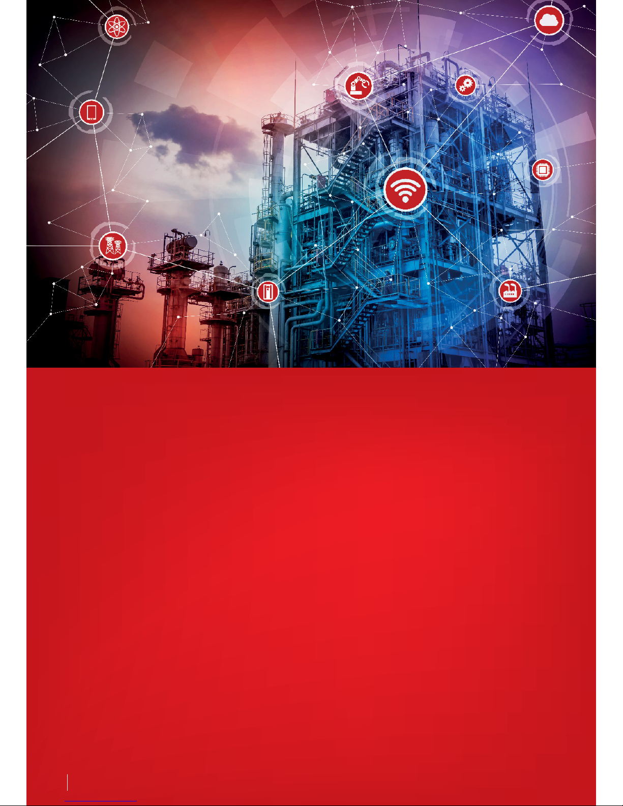
Seamlessly into the future
The fourth Industrial Revolution, or
Industry 4.0, builds on the progress of
automation by introducing elements
of interconnectivity, data acquisition,
machine learning and intelligent
applications of analytics. AC drives play
an important and powerful part in
this transition by being the first point
of interaction between sensors from
the process, the motor in operation
and communicating this information
via communications bus to a central
control location.
At Danfoss Drives, we live and
breathe Industry 4.0, with the VLT®
AutomationDrive representing the
latest and best technologies in the
drives industry. When you choose the
VLT® AutomationDrive, you can count
on the intelligent drive functions,
application know-how, proven quality
and reliability, and the support you
need to make a seamless transition into
Industry 4.0 and beyond.
The VLT® AutomationDrive offers:
Web-based configuration, Electronic
Data Interchange (EDI), transparent
order management
Access to drawings, engineering
diagrams, and ePlan macros
Simulation tools such as Danfoss
HCS for harmonic calculation and
Danfoss ecoSmart™ for motor-drive
system efficiency calculations
Compatibility with all industry-
leading motor and fieldbus
technologies
Embedded intelligence for
adaptability to evolving application
needs
Flexible interface to the drive
data from multiple access points
including: directly at the drive, via
mobile applications, through an
integrated web server and via cloud
connectivity
Page 5
It’s easy to sum up the qualities of
the VLT® AutomationDrive in just two
words – consistently awesome.
Throughout the entire lifecycle of your
application, the VLT® AutomationDrive
provides benefits that not only save
you time and money, but also help
optimize your process while providing
the flexibility and reliability to meet
your current and future demands.
Awesome versatility
Modular and adaptable, the
VLT® AutomationDrive fits into any
environment. It can be relied on to
meet all your needs whether you have
a single application or a variety of
different ones.
Its cutting-edge thermal design
and unique back-channel cooling
for drives above 90 kW make
VLT® AutomationDrive one of the
most compact and cost-efficient
drives in the market.
Consistently awesome
Simple start-up
VLT® AutomationDrive is robust and
intelligent, but at the same time quick
and easy to install and provides years of
reliable operation.
Intelligent operation
VLT® AutomationDrive has a big brain
ready to be put to work to control your
applications effectively, efficiently and
reliably.
High availability
Once installed, you can trust
VLT® AutomationDrive to provide
troublefree operation. New intelligent
maintenance features and a range of
DrivePro® services proactively improve
productivity, performance and uptime.
5| Content | Danfoss Drives · DKDD.PB.302.A8.02
Do it differently
Know-how and experience
Proven quality
DrivePro® services
A
w
e
s
o
m
e
v
e
r
s
a
t
i
l
i
t
y
S
i
m
p
l
e
s
t
a
r
t
-
u
p
O
p
t
i
m
i
z
e
d
p
e
r
f
o
r
m
a
n
c
e
I
n
t
e
l
l
i
g
e
n
t
o
p
e
r
a
t
i
o
n
Page 6

Before any wires are connected or power is applied,
your expectations of an AC drive determine whether
or not it is the correct fit for your application. An awesome
combination of functionality, suitability for your
environment and the availability of comprehensive
engineering tools make the VLT® AutomationDrive FC 300
Series an AC drive you can feel absolutely confident
selecting no matter your needs.
Designed for easy
integration in any
application
Fits in any environment
VLT® AutomationDrive can be installed
wherever it best suits your application
– close to the motor, located centrally
in an electrical panel or outdoors.
Its wide variety of enclosure class,
conformal coating and ruggedization
options reduce maintenance costs and
ensure reliable operation in a range
of challenging environments. A wide
operating temperature range of -25
°C to +50 °C adds additional peace of
mind when your applications take your
drive to the extremes.
Modular and adaptable
The VLT® AutomationDrive is built on a
flexible, modular design concept that
provides an extraordinarily versatile
motor control solution. The drive
is equipped with a wide range of
industry features that enables optimal
process control, higher quality output
and reduced costs related to spare
parts and service. The book-style
mounting takes advantage of this
modular construction principle,
allowing for more drives to fit into less
space.
Application flexibility
When you have a variety of
applications, it’s best to select an AC
drive that you can count on to meet
all your needs. Whether operating
pumps, conveyors, palletizers or
material treatment equipment, the VLT®
AutomationDrive delivers the optimum
control you want for reliable operation,
all day long.
Reduced harmonic impact
The ability to predict the impact of
adding AC drives to your facility is
critical to keeping costs low. The
Danfoss HCS tool allows you to
calculate how much harmonic content
to expect before you install your drive
and avoid additional costs of harmonics
and harmonic mitigation equipment
on your facility. The availability of low
harmonic drives, 12-pulse drives and
low harmonic power options further
minimizes harmonic impact.
Compact and efficient
When your application requires more
power, you don’t want to have to
increase the space needed for an
AC drive. Thanks to its cutting-edge
thermal design, VLT® AutomationDrive
is one of the most compact air-cooled
drives on the market in the range of
90 kW to 800 kW at 500 V. Combining
this best-in-class power density with
unique back-channel cooling further
reduces costs associated with cooling
while keeping the space required to a
minimum.
5
Awesome versatility
reasons to choose
the VLT® AutomationDrive
1. Fits in any environment
2. Modular and adaptable
3. Application flexibility
4. Reduced harmonic impact
5. Compact and efficient
6 DKDD.PB.302.A8.02 | Content |
Page 7

Your choice of AC drive should reduce the time it takes
to get your application up and running without sacrificing
any features or functionality. The VLT® AutomationDrive
FC 300 Series is designed to simplify every step in the startup process – from wiring to programming to operation –
and reliably deliver what you need for your application.
Designed with fast
and easy start-up in mind
Easy installation
All I/O terminals are pluggable and
spring-loaded and each has dualconnector configuration making wiring
easy and flexible. Drives with high
environmental enclosure ratings can
also be ordered with pre-threaded
cable gland openings to allow for an
easy and reliable way to install your
drive in harsh environments.
Dedicated application
functionality
A versatile drive doesn’t have to mean
that your drive is complicated to
commission. Application-dedicated
functions in the VLT® AutomationDrive
perfectly balance ease and robustness
to deliver reliable performance
regardless of the application. Features
such as droop functionality for load
sharing, integrated brake control
for the safe operation of hoists and
the integrated process controller for
demand-based pumping help to save
time and money during start-up.
Optimized motor control
Automatic Motor Adaptation (AMA)
is a powerful algorithm that tests
and adjusts the drive to the unique
traits of your motor, improving overall
control and operating efficiency.
Enhancements to the AMA for both
asynchronous and PM motors means
the process takes place in just a few
milliseconds without spinning the
motor. This enhanced AMA II, running
before every start, ensures that the
motor parameters are always calibrated
to the specific operating conditions
increasing motor control accuracy.
Tailored and tested
Every VLT® AutomationDrive is delivered
from the factory exactly as you have
configured it. Every drive is built with
care and completely tested at full load
against an AC motor prior to shipping,
with your selected options already
installed, which ensures that your drive
will operate just as you expect it to.
Powerful PC tools
The VLT® Motion Control Tool MCT 10
is a PC tool designed with your drive
in mind. Powerful features, like the
Motor Setup and Functional Safety
Setup tools, allow fast and easy
commissioning of your application.
MCT 10 includes the VLT® Software
Customizer. Use it to create tailored
Smart Assisted Startup wizards for
accurate commissioning of your drive;
or to define a unique set of customerspecific initial values for common
parameters that can be loaded in your
drive to replace factory default values.
5
Simple start-up
reasons to choose
the VLT® AutomationDrive
1. Easy installation
2. Dedicated application
functionality
3. Optimized motor control
4. Tailored and tested
5. Powerful PC tools
7| Content | DKDD.PB.302.A8.02
Page 8

The VLT® AutomationDrive FC 300 Series is installed in a
wide variety of demanding applications and environments.
Regardless of your application’s needs, you can count on
the VLT® AutomationDrive to deliver the capabilities for
long, worry-free operation in even the most sensitive of
environments.
Extensive functionality for
high-performance operation
Integrated Motion Controller
The performance of the VLT®
AutomationDrive FC 302 is enhanced
without complexity thanks to the
Integrated Motion Controller (IMC).
Providing motion functionality,
high-precision scaled positioning
and synchronizing tasks are simple
to perform with or without encoder
feedback, and commissioning is
fast and safe. IMC is configurable by
parameters – no special programming
language is required. No additional
modules or hardware are necessary.
Robust four-quadrant control
Applications, such as extruders
and separators, place heavy
demands on your AC drive. The
VLT® AutomationDrive can meet
your demands by providing reliable
operation in both motoring and
generating phases of operation.
Accurate torque controls, especially
through zero speed where the key
challenges lie, result in smooth and
continuous operation, saving both time
and money.
Low noise operation
Unfiltered AC drives produce
electromagnetic interference (EMI)
– both conducted and and emitted.
This interference can negatively impact
sensitive equipment. Built-in EMC/
RFI protection with screened motor
cables to Residential Category C1 (to
50 m) and C2 (to 150 m) provides the
ability to operate without additional
and expensive filters, further increasing
reliability and reducing interference
with sensitive electronics.
Easy PLC integration
VLT® AutomationDrive is compatible
with PROFINET, PROFIBUS DP-V1,
DeviceNet, EtherNet/IP, EtherCAT,
POWERLINK, CANopen and Modbus
TCP protocols. All Ethernet options
feature dual-ports with a built-in switch
or HUB (POWERLINK). Some of the
Ethernet technologies also support ring
topology for higher availability and fast
installation. Fieldbus configuration files,
pretested function blocks and add-on
instructions are available for easy, lowrisk, integration into your PLC system.
High-efficiency operation
New standards in Ecodesign have
been published focusing on energy
efficiency of AC drives and drive-motor
systems. As these standards increase
the focus on the efficiency of AC drives
worldwide, it’s important to know
that, with the VLT® AutomationDrive,
you can count on having a foundation
to meet these coming requirements.
Using Danfoss ecoSmart™, you can
quickly determine the IE class of your
AC drive, the IES class of your specific
motor-drive system and the part-load
efficiency of your drive.
5
Intelligent operation
reasons to choose
the VLT® AutomationDrive
1. Integrated Motion Controller
2. Robust four-quadrant control
3. Low noise operation
4. Easy PLC integration
5. High-efficiency operation
8 DKDD.PB.302.A8.02 | Content |
Page 9

Unplanned downtime can be costly – both in terms of
maintenance and lost production. Enhancements in the
VLT® AutomationDrive provide more information about
your devices and their performance, and a range of services
optimizes their availability.
Leveraging digitalization
to reduce maintenance costs
Intelligent troubleshooting
When something goes wrong with
your process, the more data you have,
the easier it is to pinpoint and quickly
resolve the cause. New, intelligent
maintenance features utilize the VLT®
AutomationDrive’s various sensors to
record and store 2-3 seconds of realtime information around an Alarm,
Warning or other defined trigger. This
data from up to the last 20 events
is then stored in the memory of the
drive from where it can be retrieved
and inspected within MCT 10. The
addition of the Real Time Clock option
allows the events to be time and
date stamped, providing even more
actionable data than ever before.
Wireless connectivity
The new VLT® Wireless Communication
Panel LCP 103 provides wireless
connectivity to your VLT® AutomationDrive using the MyDrive® Connect app
for iOS and Android devices. It allows
full and secure access to the drive for
easy commissioning, operation and
maintenance on your smart devices.
Use the advanced LCP copy function to
back up parameters to the storage of
the LCP 103 or your smart device.
Remote access
Offsite accessibility allows for easier
and faster access to both remote
facilities or to large numbers of installed
drives. Utilizing the integrated and
modernized interface of the web server
in the Ethernet-based communication
options, each drive can be remotely
accessed and monitored for operation
and diagnostics purposes saving time
and costs.
Intuitive maintenance
The Danfoss VLT® AutomationDrive
features both preventive and predictive
maintenance functions that provide for
worry-free operation while reducing
maintenance costs and unplanned
downtime. Preventive maintenance
functions can be used to schedule
proactive maintenance alerts based
on running time of the drive and
triggering alerts, visible on the LCP and
transferable over fieldbus. Predictive
maintenance functions turn your drive
into a configurable smart sensor that
continuously monitors the condition
of your motor and application based
on standards and guidelines such as
the ISO 13373 standard for Condition
Monitoring and Diagnostics of
Machines or the VDMA 24582 guideline
for condition monitoring.
DrivePro® services
Danfoss Drives’ comprehensive
portfolio of services spans the entire
lifecycle of your drives. As well as
traditional service functions that
improve productivity, performance and
uptime, digitalization and the Internet
of Things play valuable roles in our
range of support and value-adding
services. The drives themselves interact
closely with their surrounding systems
and processes. Built-in functionality
allows them to collect and share
data that is visible to maintenance
personnel, Danfoss service teams, and
3rd-party service providers for fast and
remote monitoring purposes.
5
Optimized
performance
reasons to choose
the VLT® AutomationDrive
1. Intelligent troubleshooting
2. Wireless connectivity
3. Remote access
4. Intuitive maintenance
5. DrivePro® services
9| Content | DKDD.PB.302.A8.02
Page 10
Speaks your language
When it comes to working with
advanced technologies, such as AC
drives, it is fairly easy to feel lost while
navigating through hundreds of
parameters. Using a graphical interface
makes this process much easier;
especially when it lists parameters
in your native language. As many as
28 language options are available,
including several Cyrillic, Arabic (right
to left) and Asian options.
Additionally, the ability to save up
to 50 user-selectable parameters
further simplifies interactions with key
parameter settings for your unique
application.
motor and remain confident that the
system will perform to the highest
possible standards.
As an independent manufacturer of AC
drive solutions, you can count on
Danfoss to support all commonly used
motor types and foster ongoing
development as new technologies
emerge.
Flexible, modular and adaptable
Built to last
Free to equip
The VLT® AutomationDrive can
optimally control nearly all standard
industrial motor technologies,
including Asynchronous, IPM, SPM,
Synchronous Reluctance and PM
assisted Synchronous Reluctance
motors. This means that system
designers, OEMs and end users are free
to connect the drive to their selected
A VLT® AutomationDrive is built on a flexible, modular
design to provide an extraordinarily versatile motor
control solution. The drive is equipped with a wide range
of industry features that enable optimal process control,
higher quality output and reduce costs related to spare
parts and service.
10 Danfoss Drives · DKDD.PB.302.A8.02 | Content |
Page 11

Power range
200-240 V
High overload
208 V ........................1.8-143 A IN, 0.25-37 kW,
230 V .........................1.8-170 A IN, 0.34-50 Hp
Normal overload
208 V ........................ 1.8-170 A IN, 0.25-45 kW
230 V .........................1.8-170 A IN, 0.34-60 Hp
380-500 V
High overload
400 V .................. 1.3-1460 A IN, 0.37-800 kW,
460 V ................... 1.2-1380 A IN, 0.5-1200 Hp
Normal overload
400 V ................ 1.3-1720 A IN, 0.37-1000 kW
460 V ................... 1.2-1530 A IN, 0.5-1350 Hp
525-600 V
High overload
575 V .............................1.7-100 A IN, 1-100 Hp
Normal overload
575 V .............................1.7-131 A IN, 1-120 Hp
525-690 V
High overload
575 V ................... 1.6-1260 A IN, 1.5-1350 Hp
690 V ...................1.6-1260 A IN, 1.1-1200 kW
Normal overload
575 V ................... 1.6-1415 A IN, 1.1-1550 Hp
690 V ...................1.6-1415 A IN, 1.1-1400 kW
Ingress protection ratings
IEC: IP00, IP20, IP21, IP54, IP55, IP66
UL: Chassis, Type 1, Type 12, Type 4X
690 V
The 690 V versions of VLT®
AutomationDrive FC 302 units for
the power range from 1.1 kW up
to 1400 kW can control motors
down to 0.37 kW without stepdown transformer. This enables you
to choose from a broad variety of
compact, reliable and efficient drives
for demanding production facilities
operating from 690 V mains networks.
Reduce costs with
compact drives
A compact design and efficient heat
management enable the drives to take
up less space in control rooms and
panels, thereby reducing initial costs.
Compact dimensions are also an
advantage in applications where
drive space is restricted, making it
possible for designers to develop
smaller applications without being
forced to compromise on protection
and grid quality. For example, VLT®
AutomationDrive FC 302 in a D or E
enclosure size is 25-68% smaller than
equivalent drives.
Despite the compact dimensions,
all units are nevertheless equipped
with integrated DC link chokes and
EMC filters, which help to reduce grid
pollution and reduce cost and efforts
for external EMC components and
wiring.
The IP20 version is optimized for
side-by-side mounting in cabinets to
50 °C without derating and features
covered power terminals to prevent
accidental contact. The AC drive can
also be ordered with an optional brake
chopper in the same package size.
Control and power cables are fed in
separately at the bottom.
The AC drives combine a flexible
system architecture that allows them
to be adapted to specific applications,
with a uniform user interface across all
FC 301 FC 302
Power range [kW] 200-240 V 0.25-37 0.25-37
Power range [kW] 380-(480) 500 V 0.37-75 (480 V ) 0.37-800 (500 V )
Power range [kW] 525-600 V – 0.75-75
Power range [kW] 525-690 V – 1.1-1400
Flux vector control –
Cable length – screened/unscreened
25/50m (A1 only),
50/75m
150/300 m
Permanent magnet motor operation
(w/wo feedback)
–
Safety function Safe Torque Off (STO – EN 61800-5-2) Optional (A1 only)
Scan interval/response time ms 5 1
Output frequency (OL) 0.2-590 Hz
0-590 Hz,
(600-1000 Hz)*
Max load (24 V DC) for analog output and
control card [mA]
130 200
Programmable digital input 5 (4) 6 (4)
Programmable digital output changeable 1 2
Programmable relay output 1 2
* For frequency up to 1000 Hz please contact your local Danfoss partner.
Choose the adequate performance level
Special needs require special features and performance
power classes. This allows you to adapt
the drive to the exact needs of your
specific application. As a result, project
work and costs are subsequently
reduced. The easy-to-use interface
reduces training requirements. The
integrated SmartStart guides users
quickly and efficiently through the setup process, resulting in fewer faults due
to configuration and parameterization
errors.
11| Content | Danfoss Drives · DKDD.PB.302.A8.02
Page 12
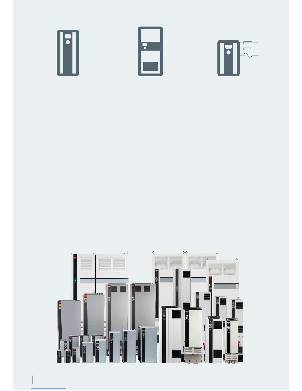
Stand-alone drives
No need to compromise
Can’t make space for a cabinet? Now
there is no need. VLT® drives are so
robust that you can mount them
virtually anywhere, even right beside
the motor. Equipped for the toughest
of environments, they suit your
application, no matter the requirement.
More uncompromising features:
Enclosure types rated up to
IP66/UL Type 4X
Full EMC compliance according
to international standards
Ruggedized and coated PCBs
Wide temperature range, operating
from -25 °C to +50 °C without
derating
Motor cable lengths up to 150 m
as standard, with uncompromised
performance
Enclosed drives
Win time
VLT® drives are designed with the
installer and operator in mind to save
time on installation, commissioning
and maintenance.
VLT® enclosed drives are designed for
full access from the front. Just open the
cabinet door and all components can
be reached without removing the drive,
even when mounted side by side.
More time-saving features:
An intuitive user interface with an
award-winning Local Control Panel
(LCP) and common control platform
that streamlines start-up and
operating procedures
Robust design and advanced
controls make VLT® drives virtually
maintenance free
Modules
Win space
The compact design of high-power
VLT® drives makes them easy to fit
even in small spaces. Integrated filters,
options and accessories provide
additional capabilities and protection
without increasing the enclosure size.
More space-saving features:
Built-in DC link reactors for harmonic
suppression eliminate the need for
higher loss external AC line reactors
Optional built-in RFI filters are
available throughout the power
range
Optional input fuses and loadshare
terminals are available within
standard enclosures
In addition to the many valuable
features that VLT® drives offer as
standard, there are numerous other
control, monitoring and power
options available in pre-engineered
factory configurations
12 Danfoss Drives · DKDD.PB.302.A8.02 | Content |
Page 13
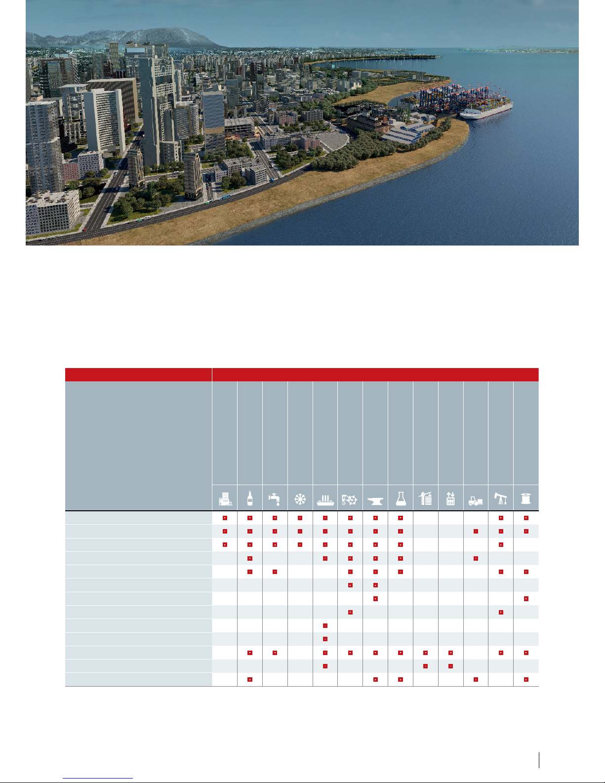
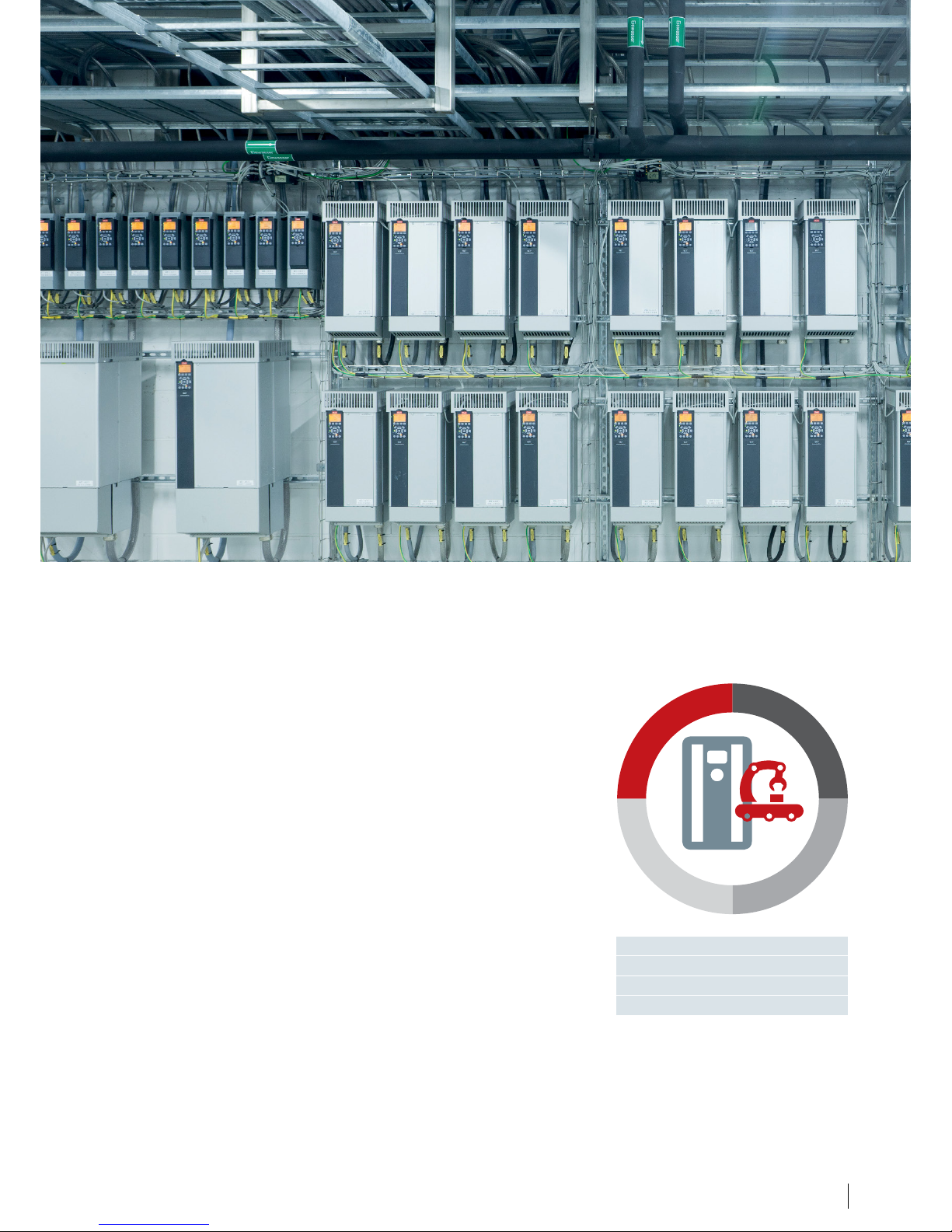
The VLT® AutomationDrive is optimized to create value for you, enabling maximum
performance in all major applications irrespective of industry.
Application flexibility to boost your business
Applications Industries
HVAC
Food and Beverage,
Packaging
Water and Wastewater
Refrigeration
Marine and Offshore
Mining and Minerals
Metals
Chemical
Cranes and Hoists
Elevators and
Escalators
Material handling
Oil and Gas
Textile
Pumps
Fans
Compressors
Conveyors
Process, material treatment
Mills, drums, kilns
Winding, unwinding
Drilling
Propulsion, thrusters
Winches
Vertical and horizontal movement
Power conversion generation, smart grids
Positioning, synchronization
13| Content | Danfoss Drives · DKDD.PB.302.A8.02
Page 14
Perform high-precision positioning
and synchronization, simply using an
AC drive. With the Integrated Motion
Controller (IMC) functionality, the
VLT® AutomationDrive FC 302
replaces more complex positioning
and synchronization controllers, to save
time and cost.
Positioning and synchronization
operations are typically performed
using a servo drive or a motion
controller. However, many of these
applications do not actually require
the dynamic performance available
from a servo drive.
Therefore the FC 302 with IMC is a costeffective, high-performance alternative
to servo in single-axis positioning and
synchronizing applications.
Use IMC for many applications that
have been solved with servo drives
until now, such as:
n Rotary tables
n Cutting machines
n Packaging machines
Encoderfree
to save costs and
reduce complexity
Use FC 302 to run an induction or PM
motor with or without motor feed-
back – with no need for additional
hardware. With sensorless control (no
motor feedback) best performance is
achieved with a PM motor. The performance of sensorless control of induction motors is however sufficient for
less-demanding applications.
With IMC you save time and cost:
n No advanced programming and
fewer components means fewer
hours needed for engineering,
installation and commissioning
n Save further cost for a feedback
device, cabling and installation by
using sensorless control
n To save cost for a home sensor and
cabling, use the “homing on torque
limit” function
The IMC solution provides
easy and safe set-up:
n Configuration via parameters, with
no advanced programming required.
Reduced complexity will minimize
the risk of errors
n To add more functionality, use the
Smart Logic Controller (SLC), which
is fully compatible with IMC
n To realign the home position
during operation, use the “home
synchronizing” function
Integrated motion controller – for positioning
and synchronization applications
14 Danfoss Drives · DKDD.PB.302.A8.02 | Content |
Page 15
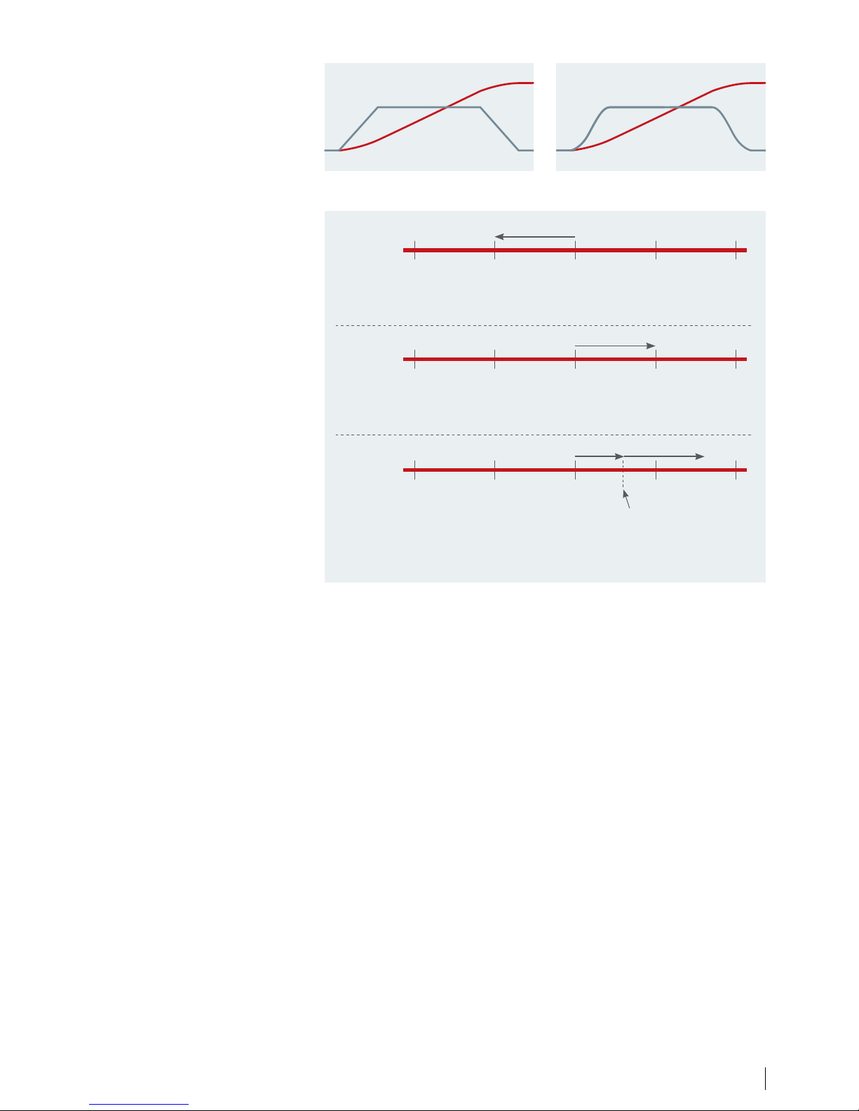
Positioning
In positioning mode, the drive controls
movement over a specific distance
(relative positioning) or to a specific
target (absolute positioning). The drive
calculates the motion profile based on
target position, speed reference and
ramp settings (see the examples in Fig. 1
and Fig. 2 on the right).
There are 3 positioning types using
different references for defining the
target position:
n Absolute positioning
Target position is relative to the
defined zero point of the machine.
n Relative positioning
Target position is relative to
the actual position of the machine.
n Touch probe positioning
Target position is relative to a signal
on a digital input
This illustration (Fig. 3) shows the
different resulting target with a set
target position (reference) of 1000 and
starting position of 2000 for each of the
positioning types.
Synchronizing
In synchronizing mode, the drive follows the position of a master; multiple
drives can follow the same master. The
master signal can be an external signal,
for example, from an encoder, a virtual
master signal generated by a drive or
master positions transferred by fieldbus.
Gear ratio and position offset is adjustable by parameter.
Homing
With sensorless control and closed
loop control with an incremental
encoder, homing is required to create
a reference for the physical position of
0 1000 2000 3000 4000
With absolute positioning, the drive moves backwards from the starting position
of 2000 to the absolute position of 1000 related to 0.
0 1000 2000 3000 4000
With relative positioning, the drive moves a distance of 1000 forward from
the starting position of 2000 ending at position 3000.
0 1000 2000 3000 4000
With touch probe positioning, the drive starts moving forward from the starting
position of 2000, detects the touch probe sensor and moves a distance of 1000
forward from the position of the touch probe sensor.
Absolute
Relative
Touch probe
Touch probe sensor
Fig. 3. IMC supports 3 positioning modes
Fig. 1. Motion profile with linear ramps Fig. 2. Motion profile with S-ramps
the machine after power up. There are
several home functions with and without sensor to choose from. The home
synchronizing function can be used to
continuously realign the home position
during operation when there is some
sort of slip in the system. For example
in case of sensorless control with an
induction motor or in case of slip in the
mechanical transmission.
Position Position
SpeedSpeed
15| Content | Danfoss Drives · DKDD.PB.302.A8.02
Page 16
Expand the standard functionality of a VLT® AutomationDrive
with energy-enhancing motion control options.
Increase productivity
and performance
Replacing mechanical controls with
intelligent, energy-saving electronic
solutions is an effective way to reduce
both installation and daily running
costs.
The ability to set and control the
packaging application with greater
precision also reduces packaging errors
and equipment breakdowns.
The result is a reliable, highquality process that increases
both productivity and bottom line
performance.
Reduce installation costs
Replacing mechanics by electronic
synchronizing or cam control increases
flexibility while reducing costs. For
example, electronic cam control, a
standard feature in the VLT® Motion
Control Option MCO 305, both adds
Increase precision, accuracy and speed
new functionalities and removes the
need for mechanical cam discs and
boxes.
Increase capacity
In other cases, manufacturers might
want to increase the capacity of their
packaging application. This can be
achieved with the VLT® Synchronizing
Controller MCO 350, which offers
unparalleled synchronizing control
and can be set up easily via the userfriendly control panel on the VLT®
AutomationDrive.
As well as increasing the performance,
the controller adds extra value by
being an intelligent way to simplify the
control system.
No matter which option you choose,
the benefits of freedom of control and
operational efficiency will provide a fast
return on your investment.
Add flexibility to
applications such as
Printing lines
Bottle washers
Conveyor belts
Packaging systems
Material-handling systems
Palletizers
Indexing tables
Storage systems
Pick-and-place systems
Positioning on the fly
Foil wrapping
Flow packing
Filling and sealing
Crane, lift and hoist applications
Product-rejection systems
Winder applications
16 Danfoss Drives · DKDD.PB.302.A8.02 | Content |
Page 17
safety fieldbus. This interconnection
enables activation of Safe Torque Off
(STO) irrespective of where a hazard
occurs. The safety functions of the MCB
152 are implemented according to EN
IEC 61800-5-2.
The MCB 152 supports PROFIsafe
functionality to activate integrated
safety functions of the VLT®
AutomationDrive from any PROFIsafe
host, up to Safety Integrity Level SIL
2 according to EN IEC 61508 and EN
IEC 62061, Performance Level PL d,
Category 3 according to EN ISO
13849-1.
Quick commissioning
Parameter configuration is fully
integrated into the VLT® Motion
Control Tool MCT 10 and enables
simple start-up and easy maintenance.
Visual instructions in MCT 10 ensure
both fault-free wiring and that safety
parameters are correctly transferred
from the PC to the drive.
The software also offers easy diagnosis
and a dynamic commissioning report
which can be used for supplying
certification documentation necessary
for safety acceptance tests.
module is certified according to ISO
13849-1 up to PL d as well as IEC 61508/
IEC 62061 up to SIL 2 and provides
SS1 and SLS (SMS) functionality. The
option can be used in low and high
demand applications. SS1 offers ramp
and time based functionality. SLS can
be configured both with and without
ramp down on activation.
VLT® Safety Option MCB 152
The VLT® Safety Option MCB 152
operates the safety functions of an
AC drive via the PROFIsafe fieldbus in
combination with the VLT® PROFINET
MCA 120 fieldbus option. Central
and decentral drives located at
different machinery cells can easily
be interconnected with the PROFIsafe
Protect both equipment
and operators
The VLT® AutomationDrive FC 302
is delivered as standard with the
STO (Safe Torque Off ) function in
compliance with ISO 13849-1 PL d and
SIL 2, according to IEC 61508/IEC 62061.
This safety function can be extended
to include SS1, SLS, SMS, safe jog
mode, etc. with the VLT® Safety Option
MCB 150 Series. The speed monitoring
functions are available both with and
without speed feedback.
VLT® Safety Option
MCB 150 and MCB 151
The MCB 150 and MCB 151 can be
integrated directly in the AC drive
and is prepared for future connection
to common safety bus systems. The
Tailored safety
Before
AC drive
without STO
Safety
module
Contactors
Actuator
After
AC drive
with STO (FC 302)
Actuator
17| Content | Danfoss Drives · DKDD.PB.302.A8.02
Page 18

networks are easier to maintain,
while providing improved systems
performance.
User friendly and fast setup
Danfoss fieldbuses can be configured
via the drive’s local control panel, which
features a user-friendly interface with
support for many user languages.
Real-time information is becoming
increasingly important in industrial
automation and control systems as
we progress further into Industry 4.0.
Immediate access to data increases
transparency in production facilities,
while making it possible to optimize
system performance, collect and
analyze system data and provide
remote support around the clock from
anywhere in the world.
Regardless of your application or your
preferred communication protocol, AC
drives have an extremely wide variety
of communication protocols to select
from. In this way you can ensure that
the AC drive integrates seamlessly into
your chosen system providing you the
freedom to communicate however you
see fit.
Increase productivity
Fieldbus communication reduces
capital costs in production plants. In
addition to the initial savings achieved
through the significant reduction in
wiring and control boxes, fieldbus
Web server dashboard
Free to connect
The drive and fieldbus can also be
configured using the software tools
that support each drive family. Danfoss
Drives offers fieldbus drivers and PLC
examples for free from the Danfoss
Drives website to make integration to
your system even easier.
18 DKDD.PB.302.A8.02 | Content |
Page 19

VLT® Software Customizer
VLT® Software Customizer allows you
to customize the commissioning
experience to best fit your needs. It is
a tool that enables you to simply and
quickly create and test your desired
setup using the simulator before
uploading it to a real drive.
The VLT® Software Customizer consists
of three main features:
SplashScreen allows you to create
a custom splash screen for when the
drive starts up. You can use the builtin editor to create an image from
blank or import an existing image
from a library or from your computer
and adapt it to the VLT®.
InitialValues allows you to set a
new default value for virtually any
parameter.
SmartStart allows you to create
a custom start-up wizard to go
through exactly the parameters you
need.
The VLT® Motion Control Tool MCT 10
is an interactive tool for quick and easy
online/offline configuration of a VLT®
drive or soft starter using a PC. You
can also use the tool to configure the
communication network and to back
up all your relevant parameter settings.
With MCT 10, you can control and
configure your system simultaneously
and monitor your entire system more
effectively for faster monitoring,
diagnosis, troubleshooting (alarms/
warnings) and better preventive
maintenance. Starting with version
4.00, MCT 10 includes even more
features that enhance usability.
Status plug-in
The readouts for various status and
control words, relay inputs and outputs
that are available over the fieldbus
have been greatly improved. We have
combined these signals into a single
plug-in that shows you much more
information. You’ll be able to see right
away if a certain relay or bit is on or off,
and what exact command the drive has
been configured with, saving you time.
Motor plug-in
The motor plug-in makes it easier to
select the needed motor type and to
parameterize the drive accordingly.
Simply select the required motor type,
and the corresponding parameters
are listed together with a description
guiding you on how to set the correct
value. The motor types supported by
the motor plug-in are:
Asynchronous
PM, non-salient SPM
PM, salient IPM
Synchronous Reluctance (SynRM)
Customized commissioning experience
19| Content | Danfoss Drives · DKDD.PB.302.A8.02
Page 20

1. Enclosure
The drive meets requirements for
enclosure class IP20/Chassis. IP21/
UL Type 1, IP54/UL Type 12, IP55/UL
Type 12 or IP66/UL Type 4X.
2. EMC and Network effects
All versions of VLT® AutomationDrive
comply as standard with EMC
limits B, A1 or A2 according to the
EN 55011 norm and IEC618003 Category C1, C2 and C3. The
standard integrated DC coils ensure
low harmonic load on the network
according to EN 61000-3-12 and
increase the lifetime of the DC link
capacitors.
3. Protective coating
The electronic components are,
as standard, coated as per
IEC 60721-3-3, class 3C2. For harsh
and aggressive environments,
coating as per IEC 60721-3-3, class
3C3 is available.
4. Removable fan
Like most of the elements, the
fan can be quickly removed and
remounted for easy cleaning.
5. Control terminals
Specially developed removable
spring-loaded cage clamps add
to reliability and facilitate easy
commissioning and service.
6. Fieldbus option
All major industrial fieldbuses are
supported. See complete list of
available fieldbus options on
page 41.
Delivered fully assembled and tested to meet your specific requirements
Modular simplicity – A, B and C enclosures
7. I/O options
The general purpose I/O, relay,
safety and thermistor expands the
flexibility of the drives.
8. Display option
Danfoss drives’ renowned
removable Local Control Panel (LCP)
has an improved user interface.
Choose between 28 built-in
languages (including Chinese) or
have it customized with your own.
Languages can be changed by the
user. Wireless version available.
Alternatively the drive can be
commissioned via the built-in USB/
RS485 connection or through
fieldbus options with the VLT®
Motion Control Tool MCT 10 PC tool.
4
8
2
3
9
5
7
6
1
20 Danfoss Drives · DKDD.PB.302.A8.02 | Content |
Page 21

9. 24 V supply or RTC
A 24 V supply option to keep the
control section and any installed
option functioning during power
failure. An extended version
combines a Real-time Clock with
a battery in one D-option.
10. Mains switch
This switch interrupts the mains
supply and has a free useable
auxiliary contact.
Safety
Extended range of integrated
functional safety. Please see chapter
“Tailored safety” on page 17.
4
3
9
6
7
5
8
10
2
1
The VLT® Wireless Communication
Panel LCP 103 (8) communicates
with MyDrive® Connect – an app
which can be downloaded to iOSand Android-based smart devices.
MyDrive® Connect offers full access
to the drive making it easier to
perform commissioning, operation,
monitoring and maintenance tasks.
Utilizing the active point-to-point
wireless connection, maintenance
personnel can receive real-time error
messages via the app to ensure a
quick response to potential issues
and reduce downtime.
VLT® Wireless Communication Panel LCP 103
21| Content | Danfoss Drives · DKDD.PB.302.A8.02
Page 22

1. Display options
Danfoss drives’ renowned removable
Local Control Panel (LCP) has an
improved user interface. Choose
between 28 built-in languages
(including Chinese) or have it
customized with your own. Languages
can be changed by the user.
2. Hot pluggable LCP
The LCP can be plugged in or
unplugged during operation. Settings
are easily transferred via the control
panel from one drive to another or
from a PC with MCT 10 set-up software.
3. Integrated manual
The info button makes the printed
manual virtually redundant. Users
have been involved throughout
development to ensure optimum
overall functionality of the drive. The
user group has significantly influenced
the design and functionality of the LCP.
The Automatic Motor Adaptation
(AMA), the Quick Set-Up menu
and the large graphic display make
commissioning and operation a breeze.
4. Fieldbus options
See complete list of available fieldbus
options on page 46.
5. I/O options
The general purpose I/O, relay and
thermistor expands the flexibility of the
drives.
6. Control terminals
Specially developed removable springloaded cage clamps add to reliability
and facilitate easy commissioning and
service.
7. 24 V supply
A 24 V supply keeps the VLT® drives
logically “alive” in situations when the
AC power supply is removed.
Is available in an extended version
with RTC. Real Time Clock parameters’
settings will be supported.
8. RFI filter suitable for IT grids
All high-power drives come standard
with RFI filtering according to EN
61800-3 Cat. C3/EN 55011 class A2.
A1/C2 RFI filters according to IEC 61000
and EN 61800 standards as integrated
options.
9. Modular construction
and ease of maintenance
All components are easily accessible
from the front of the drive, allowing
for ease of maintenance and side-byside mounting of drives. The drives are
constructed using a modular design
that allows for the easy replacement of
modular sub-assemblies.
10. Programmable options
A freely programmable motion
control option for user-specific control
algorithms and programs allows the
integration of PLC programs.
11. Conformally coated and
ruggedized circuit boards
All high-power drive circuit boards are
conformal coated to withstand the salt
mist test. Meets IEC 60721-3-3
Class 3C3. The conformal coating
complies with ISA (International Society
of Automation) standard S71.04 1985,
class G3. Additionally, drives in D and E
enclosures can be further ruggedized
to withstand the higher vibration needs
of certain applications.
12. Back-channel cooling
The unique design uses a back channel
to pass cooling air over heat sinks.
This design allows up to 90% of the
heat losses to be exhausted directly
outside of the enclosure with minimal
air passing through the electronics
area. This reduces temperature rise
and contamination of the electronic
components for improved reliability
and increased functional life.
As an option, the back-channel cooling
duct can be supplied in stainless
steel to provide a degree of corrosion
resistance against conditions such as
those found in salt-air environments
near the ocean.
13. Enclosure
The drive meets relevant requirements
for all possible installation conditions.
Enclosure class IP00/chassis, IP20/
chassis, IP21/UL Type 1, and IP54/UL
Type 12. A kit is available to increase
the enclosure class on enclosure size D
drives to UL Type 3R.
14. DC-link reactor
The built-in DC-link reactor ensures low
harmonic disturbance of the power
supply in accordance with IEC-610003-12. The result is a more compact
design with higher efficiencies than
competitive systems with externalmounted AC chokes.
15. Input mains option
Various input configurations are
available, including fuses, mains
disconnect switch, or RFI filter.
High-power modularity – D, E and F enclosures
The high-power VLT® AutomationDrive modules are all built on a modular
platform allowing for highly customized drives which are mass produced,
tested, and delivered from the factory.
Upgrades and further options dedicated to your industry are a matter of
plug-and-play. Once you know one, you know them all.
22 Danfoss Drives · DKDD.PB.302.A8.02 | Content |
Page 23

2
1
3
9
8
6
5
4
10
12
13
11
14
7
Efficiency is vital
for high-power drives
Efficiency is essential in the design
of the high-power VLT® drive series.
Innovative design and exceptionally
high-quality components have resulted
in unsurpassed energy efficiency.
VLT® drives pass more than 98% of
the supplied electrical energy on to
the motor. Only 2% or less is left in
the power electronics as heat to be
removed.
Energy is saved and electronics last
longer because they are not exposed
to high temperatures within the
enclosure.
Safety
Extended range of integrated
functional safety. Please see chapter
“Tailored safety” on page 17.
15
23| Content | Danfoss Drives · DKDD.PB.302.A8.02
Page 24

Engineered for cost savings
via intelligent heat management,
compactness and protection
Ruggedized for
extra protection
All Danfoss VLT® drives follow the same design principle for fast,
flexible and fault-free installation, and efficient cooling.
The AC drives are available in a broad
range of enclosure sizes and protection
ratings from IP20 to IP66 to enable
easy installation in all environments:
mounted in panels, switch rooms or
as stand-alone units in the production
area.
Cost-saving heat management
In AC drives, there is total separation
between the back-channel cooling
air and the internal electronics.
This separation greatly reduces the
airflow over the sensitive electronics,
minimizing the exposure to
In order to reduce the potential
negative effects of vibration, the drives
have been ‘ruggedized’. It is a process
that ensures that critical components
on the PCB have increased protection,
significantly reducing the risk of
malfunction while at sea.
The printed circuit boards in the drives
are also all coated in accordance with
IEC 60721-3-3 class 3C3, providing
additional protection against moisture
and dust.
Reliable operation at
engine room temperatures
up to 55 °C
VLT® drives can operate at full load in
engine rooms with 50 °C temperature
and 55 °C at reduced power close to,
for example, pumps and thrusters.
There is no need for installation in airconditioned control rooms with long
motor cables.
contaminants. At the same time, it
removes heat efficiently which helps
to prolong product life, increase
the overall availability of the system
and reduce faults related to high
temperatures.
For example, by exhausting heat
directly outside, it is possible to reduce
the size of the cooling system in the
panel or switch room. This can be
achieved with Danfoss’ extremely
efficient back-channel cooling concept,
allowing heat to be vented outside the
control room.
Spark-free design
The VLT® drives conform to the Limited
Explosion Risk requirements in The
European Agreement concerning the
International Carriage of Dangerous
Goods by Inland Waterways, as they do
not create any sparks durings normal
operation and the temperature does
not exceed 200 °C.
In daily use, the benefits are equally
clear as the energy consumption
related to cooling can be reduced
significantly. This means that designers
can reduce the size of the air
conditioning system, or even eliminate
it entirely.
Coated circuit boards
The AC drive conforms as standard to
class 3C3 (IEC 60721-3-3) to ensure long
lifetime even in harsh environments.
24 Danfoss Drives · DKDD.PB.302.A8.02 | Content |
Page 25

Back-channel
cooling gives up to
90%
reduction
in investment for air
cooling systems
Back-channel cooling
By directing air through a rear cooling
channel, up to 90% of the drive’s heat
loss is removed directly outside the
installation room.
Minimal airflow over electronics
Complete separation between backchannel cooling air and the internal
electronics ensures efficient cooling.
Panel-through cooling
An accessory mounting kit for small and
mid-range drives enables heat losses to be
directed directly outside the panel room.
25| Content | Danfoss Drives · DKDD.PB.302.A8.02
Page 26

Optimize performance
and grid protection
Built-in protection
The AC drive contains all the modules
necessary for compliance with EMC
standards.
A built-in, scalable RFI filter minimizes
electromagnetic interference, and
the integrated DC link chokes reduce
the harmonic distortion in the mains
network, in accordance with
IEC 61000-3-12. Furthermore, they
increase the lifetime of the DC link
capacitors and therefore the overall
efficiency of the drive.
These built-in components save
cabinet space, as they are integrated
in the drive from the factory. Efficient
EMC mitigation also enables the use
of cables with smaller cross-sections,
which reduces installation costs.
26 Danfoss Drives · DKDD.PB.302.A8.02 | Content |
Page 27

Use motor cables up to 300 m
The design of the AC drive makes it
a perfect choice in applications that
require long motor cables. Without
needing additional components, the
drive provides trouble-free operation
with cable lengths of up to 150 m
shielded or 300 m unshielded. This
allows the drive to be installed in a
central control room, away from the
application without affecting motor
performance.
Expand grid and motor
protection with filter solutions
Danfoss’ wide range of solutions for
harmonic mitigation ensures a clean
power supply and optimal equipment
protection, and includes:
VLT® Advanced Harmonic Filter AHF
VLT® Advanced Active Filter AAF
VLT® Low Harmonic Drives
VLT® 12-pulse Drives
Provide extra motor protection with:
VLT® Sine-wave Filter
VLT® dU/dt Filter
VLT® Common Mode Filters
Achieve optimum performance for
your application, even where the grid is
weak or unstable.
Optimized harmonic performance
Efficient harmonic mitigation protects electronics
and increases efficiency.
Harmonic distortion
Electrical interference reduces efficienc y and risks
harming equipment.
EMC Standards Conducted emission
Standards and
requirements
EN 55011
Facility operators must
comply with EN 55011
Class B
Housing
and light industries
Class A Group 1
Industrial
environment
Class A Group 2
Industrial
environment
EN/IEC 61800-3
Converter manufacturers
must conform to EN 61800-3
Category C1
First
environment, home
and office
Category C2
First
environment, home
and office
Category C3
Second
environment
Compliance
1)
1)
Compliance to mentioned EMC classes depends on the selected filter.
For further details see the design guides.
300
150
0
-150
-300
[V]
8 16 24 32 ms
300
150
0
-150
-300
[V]
8 16 24 32 ms
Discover more at drivepro.danfoss.com
Pre-sales
support
Training
DrivePro®
Services
Higher performance
More uptime
Healthier budget
Stay calm. You’re covered.
DrivePro® Retrofit
DrivePro® Extended Warranty
DrivePro® Exchange DrivePro® Remote Expert Support
DrivePro® Spare Parts
DrivePro® Preventive Maintenance
DrivePro® Start-up
DrivePro® Upgrade
DrivePro® Life Cycle
You’re covered
with DrivePro® Life Cycle service products
Get the most out of your systems, with the help of DrivePro® services
for Danfoss VLT® and VACON® drives. You get services that go beyond
simple troubleshooting, maintenance, repairs and replacements.
They also proactively improve productivity, performance and uptime.
DrivePro® app
Use the DrivePro app for fast
access to the DrivePro® services,
for improved productivity,
performance and uptime of
your systems. Find your closest
service partner, place a service
request, and register your VLT®
and VACON® drives. You can also
look up product information,
specifications and manuals for
your specific VLT® or VACON® drive
based on the nameplate product
code, or the product name.
27| Content | Danfoss Drives · DKDD.PB.302.A8.02
Page 28

28 Danfoss Drives · DKDD.PB.302.A8.02 | Content |
Connection example
This diagram shows a typical installation
of the VLT® AutomationDrive. Power
is connected to the terminals 91 (L1),
92 (L2) and 93 (L3) and the motor is
connected to 96 (U), 97 (V) and 98 (W).
Terminals 88 and 89 are used for load
sharing between drives.
Analog inputs can be connected to
the 53 (V or mA), and for 54 (V or mA)
terminals.
These inputs can be set up as either
reference, feedback or thermistor
inputs.
There are 6 digital inputs to be
connected to terminals 18, 19, 27, 29,
32, and 33. Two digital input/output
terminals (27 and 29) can be set up
as digital outputs to show an actual
status or warning or can be used as a
pulse reference signal. The terminal 42
analog output can show process
values such as 0 - Imax.
On the 68 (P+) and 69 (N-) terminals’
RS 485 interface, the drive can be
controlled and monitored via serial
communication.
3 Phase
power
input
DC bus
Switch Mode
Power Supply
Motor
Analog Output
Interface
relay1
* relay2
ON=Terminated
OFF=Open
Brake
resistor
130BC931.10
91 (L1)
92 (L2)
93 (L3)
PE
88 (-)
89 (+)
50 (+10 V OUT)
53 (A IN)
54 (A IN)
55 (COM A IN)
0/4-20 mA
12 (+24V OUT)
13 (+24V OUT)
37 (D IN)
18 (D IN)
20 (COM D IN)
10Vdc
15mA 130/200mA
+ - + -
(U) 96
(V) 97
(W) 98
(PE) 99
(COM A OUT) 39
(A OUT) 42
(P RS-485) 68
(N RS-485) 69
(COM RS-485) 61
0V
5V
S801
0/4-20 mA
RS-485
RS-485
03
+10Vdc
0/-10Vdc -
+10Vdc
+10Vdc
0/4-20 mA
0/-10Vdc -
240Vac, 2A
24Vdc
02
01
05
04
06
240Vac, 2A
24V (NPN)
0V (PNP)
0V (PNP)
24V (NPN)
19 (D IN)
24V (NPN)
0V (PNP)
27
24V
0V
(D IN/OUT)
0V (PNP)
24V (NPN)
(D IN/OUT)
0V
24V
29
24V (NPN)
0V (PNP)
0V (PNP)
24V (NPN)
33 (D IN)
32 (D IN)
1 2
ON
S201
ON
21
S202
ON=0/4-20mA
OFF=0/-10Vdc +10Vdc
95
400Vac, 2A
P 5-00
21
ON
S801
(R+) 82
(R-) 81
*
*
: Chassis
: Earth
**
The numbers represent the terminals on the drive
Page 29

Technical data
Basic unit without extensions
Main supply (L1, L2, L3)
Supply voltage
200-240 V AC
380-500 V AC
525-600 V AC
525-690 V AC
Supply frequency 50/60 Hz
Displacement power factor
(cos ф) near unity
> 0.98
Switching on input supply
L1, L2, L3
1-2 times/min.
Output data ( T1, T2, T3)
Output voltage 0-100% of supply voltage
Output frequency 0-590 Hz
Switching on output Unlimited
Ramp times 0.01-3600 s
Digital inputs
Programmable digital inputs 6*
Changeable to digital output 2 (terminal 27, 29)
Logic PNP or NPN
Voltage level 0-24 V DC
Maximum voltage on input 28 V DC
Input resistance, Ri Approx. 4 kΩ
Scan interval 5 ms
* Two of the inputs can be used as digital outputs
Analog inputs
Analog inputs 2
Modes Voltage or current
Voltage level 0 to +10 V (scaleable)
Current level 0/4 to 20 mA (scaleable)
Accuracy of analog inputs Max. error: 0.5% of full scale
Pulse inputs
Programmable pulse inputs 2*
Voltage level 0-24 V DC (PNP positive logic)
Pulse input accuracy
(0.1-1 kHz)
Max. error: 0.1% of full scale
* Two of the digital inputs can be used for pulse inputs.
Digital outputs
Programmable
digital/pulse outputs
2
Voltage level at
digital/frequency output
0-24 V DC
Max. output current
(sink or source)
40 mA
Maximum output frequency 0-32 kHz
Accuracy on frequency output Max. error: 0.1% of full scale
Analog outputs
Programmable
analog outputs
1
Current range at
analog output
0/4-20 mA
Max. load to common at
analog output (clamp 30)
500 Ω
Accuracy on analog output Max. error: 0.5 % of full scale
Control card
USB interface 1.1 (Full Speed)
USB plug Type “B”
RS485 interface Up to 115 kBaud
Max. load (10 V) 15 mA
Max. load (24 V) 200 mA
Relay outputs
Programmable relay outputs 2
Max. terminal load (AC)
on 1-3 (NC), 1-2 (NO),
4-6 (NC) power card
240 V AC, 2 A
Max. terminal load (AC -1) on
4-5 (NO) power card
400 V AC, 2 A
Min. terminal load on
1-3 (NC), 1-2 (NO),
4-6 (NC), 4-5 (NO)
power card
24 V DC 10 mA, 24 V AC 20 mA
Surroundings/external
Ingress protection class
IP: 00/20/21/54/55/66
UL Type: Chassis/1/12/3R/4X
Vibration test 0.7 g
Max. relative humidity
5-95% (IEC 721-3-3); Class 3K3
(non-condensing) during operation
Ambient temperature Max. 50 °C without derating
Galvanic isolation of all I/O supplies according to PELV
Aggressive environment Designed for 3C3 (IEC 60721-3-3)
Ambient temperature
– Operating temperature range is -25 °C to 50 °C without derating
Max 55 °C with derating
Fieldbus communication
Standard built-in:
FC Protocol
N2 Metasys
FLN Apogee
Modbus RTU
Optional:
VLT® PROFIBUS DP V1 MCA 101
VLT® DeviceNet MCA 104
VLT® CANopen MCA 105
VLT® 3000 PROFIBUS Converter MCA 113
VLT® 5000 PROFIBUS Converter MCA 114
VLT® PROFINET MCA 120
VLT® EtherNet/IP MCA 121
VLT® Modbus TCP MCA 122
VLT® POWERLINK MCA 123
VLT® EtherCAT MCA 124
VLT® 5000 DeviceNet Converter MCA 194
Protection mode for longest possible up-time
– Electronic motor thermal protection against overload
– Protection against overtemperature
– The AC drive is protected against short circuits
on motor terminals R, S, T
– The AC drive is protected against ground faults
on motor terminals U, V, W
– Protection against mains phase loss
– Real-Time Clock with battery backup
– Advanced data logging using real-time stamps
– Predictive maintenance
– Preventive maintenance
– D-option VLT® Real-time Clock Option MCB 117
Agency approvals
29| Content | Danfoss Drives · DKDD.PB.302.A8.02
Page 30

30 Danfoss Drives · DKDD.PB.302.A8.02 | Content |
[T2] 3 x 200-240 V AC – high overload
High overload (160% 1 min/10 min) Enclosure size
Type
code
Output current
(3 x 200-240 V)
Typical shaft
output power
Conti nuous
input current
Estimated
power loss
Protection rating [IEC/UL]
IP20/21 IP21 IP55 IP66
FC-302 Con. I
N
Inter. I
MAX
(60 s)
kW @
208 V
Hp @
230 V
[A] [W] Chassis Type 1 Type 12 Type 4X
PK25 1.8 2.9 0.25 0.34 2.6 21 A1*/A2 A2 A4/A5 A4/A5
PK37 2.4 3.8 0.37 0.5 3.5 29 A1*/A2 A2 A4/A5 A4/A5
PK55 3.5 5.6 0.55 0.75 5.1 42 A1*/A2 A2 A4/A5 A4/A5
PK75 4.6 7.4 0.75 1 6.6 54 A1*/A2 A2 A4/A5 A4/A5
P1K1 6.6 10.6 1.1 1.5 9.4 63 A1*/A2 A2 A4/A5 A4/A5
P1K5 7.5 12 1.5 2 10.9 82 A1*/A2 A2 A4/A5 A4/A5
P2K2 10.6 17 2.2 3 15.2 116 A2 A2 A4/A5 A4/A5
P3K0 12.5 20 3 4 18.1 155 A3 A3 A5 A5
P3K7 16.7 26.7 3.7 5 24 185 A3 A3 A5 A5
P5K5 24.2 38.7 5.5 7.5 35.2 239 B3 B1 B1 B1
P7K5 30.8 49.3 7.5 10 44.8 371 B3 B1 B1 B1
P11K 46.2 73.9 11 15 67.2 463 B4 B2 B2 B2
P15K 59.4 89.1 15 20 81 624 B4 C1 C1 C1
P18K 74.8 112 18.5 25 102 740 C3 C1 C1 C1
P22K 88 132 22 30 120 874 C3 C1 C1 C1
P30K 115 173 30 40 156 1143 C4 C2 C2 C2
P37K 143 215 37 50 195 1400 C4 C2 C2 C2
*A1 enclosure is only available as FC 301
[T2] 3 x 200-240 V AC – normal overload
Normal overload (110% 1 min/10 min) Enclosure size
Type
code
Output current
(3 x 200-240 V)
Typical shaft
output power
Conti nuous
input current
Estimated
power loss
Protection rating [IEC/UL]
IP20/21 IP21 IP55 IP66
FC-302 Con. I
N
Inter. I
MAX
(60 s)
kW @
208 V
Hp @
230V
[A] [W] Chassis Type 1 Type 12 Type 4X
PK25 1.8 2.9 0.25 0.34 2.6 21 A1*/A2 A2 A4/A5 A4/A5
PK37 2.4 3.8 0.37 0.5 3.5 29 A1*/A2 A2 A4/A5 A4/A5
PK55 3.5 5.6 0.55 0.75 5.1 42 A1*/A2 A2 A4/A5 A4/A5
PK75 4.6 7.4 0.75 1 6.6 54 A1*/A2 A2 A4/A5 A4/A5
P1K1 6.6 10.6 1.1 1.5 9.4 63 A1*/A2 A2 A4/A5 A4/A5
P1K5 7.5 12 1.5 2 10.9 82 A1*/A2 A2 A4/A5 A4/A5
P2K2 10.6 17 2.2 3 15.2 116 A2 A2 A4/A5 A4/A5
P3K0 12.5 20 3 4 18.1 155 A3 A3 A5 A5
P3K7 16.7 26.7 3.7 5 24 185 A3 A3 A5 A5
P5K5 30.8 33.9 7.5 10 30.8 310 B3 B1 B1 B1
P7K5 46.2 50.8 11 15 46.2 514 B3 B1 B1 B1
P11K 59.4 65.3 15 20 59.4 602 B4 B2 B2 B2
P15K 74.8 82.3 18.5 25 74.8 737 B4 C1 C1 C1
P18K 88 96.8 22 30 88 845 C3 C1 C1 C1
P22K 115 127 30 40 114 1140 C3 C1 C1 C1
P30K 143 157 37 50 143 1353 C4 C2 C2 C2
P37K 170 187 45 60 169 1636 C4 C2 C2 C2
*A1 enclosure is only available as FC 301
Electrical data – A, B, and C enclosures
Page 31

31| Content | Danfoss Drives · DKDD.PB.302.A8.02
[T5] 3 x 380-500 V AC – high overload
High overload (160% 1 min/10 min) Enclosure size
Type
code
Output current
Typical shaft
output power
Continuous
input
current
Estimated
power
loss
Protection rating [IEC/UL]
(3 x 380-440 V) (3 x 441-500 V) IP20/21 IP21 IP55 IP66
FC-302 Con. I
N
Inter. I
MAX
(60 s)
Con. I
N
Inter. I
MAX
(60 s)
kW @
400 V
Hp @
460 V
[A] [W] Chassis Type 1 Type 12 Type 4X
PK37 1.3 2.1 1.2 1.9 0.37 0.5 1.9 35 A1*/A2 A2 A4/A5 A4/A5
PK55 1.8 2.9 1.6 2.6 0.55 0.75 2.6 42 A1*/A2 A2 A4/A5 A4/A5
PK75 2.4 3.8 2.1 3.4 0.75 1 3.5 46 A1*/A2 A2 A4/A5 A4/A5
P1K1 3 4.8 2.7 4.3 1.1 1.5 4.3 58 A1*/A2 A2 A4/A5 A4/A5
P1K5 4.1 6.6 3.4 5.4 1.5 2 5.9 62 A1*/A2 A2 A4/A5 A4/A5
P2K2 5.6 9 4.8 7.7 2.2 3 8 88 A2 A2 A4/A5 A4/A5
P3K0 7.2 11.5 6.3 10.1 3 4 10.4 116 A2 A2 A4/A5 A4/A5
P4K0 10 16 8.2 13.1 4 5 14.4 124 A2 A2 A4/A5 A4/A5
P5K5 13 20.8 11 17.6 5.5 7.5 18.7 187 A3 A3 A5 A5
P7K5 16 25.6 14.5 23.2 7.5 10 23 255 A3 A3 A5 A5
P11K 24 38.4 21 33.6 11 15 35.2 291 B3 B1 B1 B1
P15K 32 51.2 27 43.2 15 20 46.4 379 B3 B1 B1 B1
P18K 37.5 60 34 54.4 18.5 25 54.4 444 B4 B2 B2 B2
P22K 44 70.4 40 64 22 30 64 547 B4 B2 B2 B2
P30K 61 91.5 52 78 30 40 82.5 570 B4 C1 C1 C1
P37K 73 110 65 97.5 37 50 99 697 C3 C1 C1 C1
P45K 90 135 80 120 45 60 123 891 C3 C1 C1 C1
P55K 106 159 105 158 55 75 144 1022 C4 C2 C2 C2
P75K 147 221 130 195 75 100 200 1232 C4 C2 C2 C2
*A1 enclosure is only available as FC 301
[ T5] 3 x 380-500 V AC – normal overload
Normal overload (110% 1 min/10 min) Enclosure size
Type
code
Output current
Typical shaft
output power
Continuous
input
current
Estimated
power
loss
Protection rating [IEC/UL]
(3 x 380-440 V) (3 x 441-500 V) IP20/21 IP21 IP55 IP66
FC-302 Con. I
N
Inter. I
MAX
(60 s)
Con. I
N
Inter. I
MAX
(60 s)
kW @
400 V
Hp @
460 V
[A] [W] Chassis Type 1 Type 12 Type 4X
PK37 1.3 2.1 1.2 1.9 0.37 0.5 1.9 35 A1*/A2 A2 A4/A5 A4/A5
PK55 1.8 2.9 1.6 2.6 0.55 0.75 2.6 42 A1*/A2 A2 A4/A5 A4/A5
PK75 2.4 3.8 2.1 3.4 0.75 1 3.5 46 A1*/A2 A2 A4/A5 A4/A5
P1K1 3 4.8 2.7 4.3 1.1 1.5 4.3 58 A1*/A2 A2 A4/A5 A4/A5
P1K5 4.1 6.6 3.4 5.4 1.5 2 5.9 62 A1*/A2 A2 A4/A5 A4/A5
P2K2 5.6 9 4.8 7.7 2.2 3 8 88 A2 A2 A4/A5 A4/A5
P3K0 7.2 11.5 6.3 10.1 3 4 10.4 116 A2 A2 A4/A5 A4/A5
P4K0 10 16 8.2 13.1 4 5 14.4 124 A2 A2 A4/A5 A4/A5
P5K5 13 20.8 11 17.6 5.5 7.5 18.7 187 A3 A3 A5 A5
P7K5 16 25.6 14.5 23.2 7.5 10 23 255 A3 A3 A5 A5
P11K 32 35.2 27 29.7 15 20 31.9 392 B3 B1 B1 B1
P15K 37.5 41.3 34 37.4 18.5 25 37.4 465 B3 B1 B1 B1
P18K 44 48.4 40 44 22 30 44 525 B4 B2 B2 B2
P22K 61 67.1 52 57.2 30 40 60.5 739 B4 B2 B2 B2
P30K 73 80.3 65 71.5 37 50 72.6 698 B4 C1 C1 C1
P37K 90 99 80 88 45 60 90.2 843 C3 C1 C1 C1
P45K 106 117 105 116 55 75 106 1083 C3 C1 C1 C1
P55K 147 162 130 143 75 100 146 1384 C4 C2 C2 C2
P75K 177 195 160 176 90 125 177 1474 C4 C2 C2 C2
*A1 enclosure is only available as FC 301
Page 32

32 Danfoss Drives · DKDD.PB.302.A8.02 | Content |
[T6] 3 x 525-600 V AC – high overload
High overload (160% 1 min/10 min) Enclosure size
Type
code
Output current
(3 x 525-600 V)
Typical shaft
output power
Intermittent
input current
Estimated
power loss
Protection rating [IEC/UL]
IP20 IP21 IP55 IP66
FC-302 Con. I
N
Inter. I
MAX
(60 s)
kW @
575 V
Hp @
575 V
[A] [W] Chassis Type 1 Type 12 Type 4X
PK75 1.7 2.7 0.75 1 2.7 35 A3 A3 A5 A5
P1K1 2.4 3.8 1.1 1.5 3.8 50 A3 A3 A5 A5
P1K5 2.7 4.3 1.5 2 4.3 65 A3 A3 A5 A5
P2K2 3.9 6.2 2.2 3 6.6 92 A3 A3 A5 A5
P3K0 4.9 7.8 3 4 8.3 122 A3 A3 A5 A5
P4K0 6.1 9.8 4 5 9.3 145 A3 A3 A5 A5
P5K5 9 14.4 5.5 7.5 13.8 195 A3 A3 A5 A5
P7K5 11 17.6 7.5 10 16.6 261 A3 A3 A5 A5
P11K 18 29 11 15 28 220 B3 B1 B1 B1
P15K 22 35 15 20 33 300 B3 B1 B1 B1
P18K 27 43 18.5 25 41 370 B4 B2 B2 B2
P22K 34 54 22 30 52 440 B4 B2 B2 B2
P30K 41 62 30 40 59 600 B4 C1 C1 C1
P37K 52 78 37 50 70 740 C3 C1 C1 C1
P45K 62 93 45 60 85 900 C3 C1 C1 C1
P55K 83 125 55 75 113 1100 C4 C2 C2 C2
P75K 100 150 75 100 137 1500 C4 C2 C2 C2
[T6] 3 x 525-600 V AC – normal overload
Normal overload (110% 1 min/10 min) Enclosure size
Type
code
Output current
(3 x 525-600 V)
Typical shaft
output power
Intermittent
input current
Estimated
power loss
Protection rating [IEC/UL]
IP20 IP21 IP55 IP66
FC-302 Con. I
N
Inter. I
MAX
(60 s)
kW @
575 V
Hp @
575 V
[A] [W] Chassis Type 1 Type 12 Type 4X
PK75 1.7 2.7 0.75 1 2.7 35 A3 A3 A5 A5
P1K1 2.4 3.8 1.1 1.5 3.8 50 A3 A3 A5 A5
P1K5 2.7 4.3 1.5 2 4.3 65 A3 A3 A5 A5
P2K2 3.9 6.2 2.2 3 6.6 92 A3 A3 A5 A5
P3K0 4.9 7.8 3 4 8.3 122 A3 A3 A5 A5
P4K0 6.1 9.8 4 5 9.3 145 A3 A3 A5 A5
P5K5 9 14.4 5.5 7.5 13.8 195 A3 A3 A5 A5
P7K5 11 17.6 7.5 10 16.6 261 A3 A3 A5 A5
P11K 22 24 15 20 23 300 B3 B1 B1 B1
P15K 27 30 18.5 25 28 370 B3 B1 B1 B1
P18K 34 37 22 30 36 440 B4 B2 B2 B2
P22K 41 45 30 40 43 600 B4 B2 B2 B2
P30K 52 57 37 50 54 740 B4 C1 C1 C1
P37K 62 68 45 60 62 900 C3 C1 C1 C1
P45K 83 91 55 74 83 1100 C3 C1 C1 C1
P55K 100 110 75 100 100 1500 C4 C2 C2 C2
P75K 131 144 90 120 131 1800 C4 C2 C2 C2
Page 33

33| Content | Danfoss Drives · DKDD.PB.302.A8.02
[T7] 3 x 525-690 V AC – high overload
High overload (160% 1 min/10 min) Enclosure size
Type
code
Output current
Typical shaft
output power
Conti nuous
input current
Estimated
power loss
Protection rating [IEC]
(3 x 525-550 V) (3 x 551-690 V) IP20 IP21 IP55
FC-302 Con. I
N
Inter. I
MAX
(60 s)
Con. I
N
Inter. I
MAX
(60 s)
kW @
690 V
Hp @
575 V
[A] [W] * * *
P1K1 2.1 3.4 1.6 2.6 1.1 1.5 3 44 A3 A3 A5
P1K5 2.7 4.3 2.2 3.5 1.5 2 3.9 60 A3 A3 A5
P2K2 3.9 6.2 3.2 5.1 2.2 3 5.6 88 A3 A3 A5
P3K0 4.9 7.8 4.5 7.2 3 4 7 120 A3 A3 A5
P4K0 6.1 9.8 5.5 8.8 4 5 8.8 160 A3 A3 A5
P5K5 9 14.4 7.5 12 5.5 7.5 12.9 220 A3 A3 A5
P7K5 11 17.6 10 16 7.5 10 15.8 300 A3 A3 A5
P11K 14 22.4 13 20.8 11 10 23.2 150 B4 B2 B2
P15K 19 30.4 18 28.8 15 15 31.2 220 B4 B2 B2
P18K 23 36.8 22 35.2 18.5 20 38.4 300 B4 B2 B2
P22K 28 44.8 27 43.2 22 25 46.4 370 B4 B2 B2
P30K 36 54 34 51 30 30 54 600 B4 C2 C2
P37K 43 64.5 41 61.5 37 40 72 740 C3 C2 C2
P45K 54 81 52 78 45 50 87 900 C3 C2 C2
P55K 65 97.5 62 93 55 60 105 1100 – C2 C2
P75K 87 130.5 83 124.5 75 75 129 1500 – C2 C2
*Note: T7 drives are not UL certified. Select T6 for UL certification.
[T7] 3 x 525-690 V AC – normal overload
Normal overload (110% 1 min/10 min) Enclosure size
Type
code
Output current
Typical shaft
output power
Conti nuous
input current
Estimated
power loss
Protection rating [IEC]
(3 x 525-550 V) (3 x 551-690 V) IP20 IP21 IP55
FC-302 Con. I
N
Inter. I
MAX
(60 s)
Con. I
N
Inter. I
MAX
(60 s)
kW @
690 V
Hp @
575 V
[A] [W] * * *
P1K1 2.1 3.4 1.6 2.6 1.1 1.5 3 44 A3 A3 A5
P1K5 2.7 4.3 2.2 3.5 1.5 2 3.9 60 A3 A3 A5
P2K2 3.9 6.2 3.2 5.1 2.2 3 5.6 88 A3 A3 A5
P3K0 4.9 7.8 4.5 7.2 3 4 7 120 A3 A3 A5
P4K0 6.1 9.8 5.5 8.8 4 5 8.8 160 A3 A3 A5
P5K5 9 14.4 7.5 12 5.5 7.5 12.9 220 A3 A3 A5
P7K5 11 17.6 10 16 7.5 10 15.8 300 A3 A3 A5
P11K 19 20.9 18 19.8 15 15 21.5 220 B4 B2 B2
P15K 23 25.3 22 24.2 18.5 20 26.4 300 B4 B2 B2
P18K 28 30.8 27 29.7 22 25 31.9 370 B4 B2 B2
P22K 36 39.6 34 37.4 30 30 39.6 440 B4 B2 B2
P30K 43 47.3 41 45.1 37 40 53.9 740 B4 C2 C2
P37K 54 59.4 52 57.2 45 50 64.9 900 C3 C2 C2
P45K 65 71.5 62 68.2 55 60 78.1 1100 C3 C2 C2
P55K 87 95.7 83 91.3 75 75 95.7 1500 – C2 C2
P75K 105 115.5 100 110 90 100 108.9 1800 – C2 C2
*Note: T7 drives are not UL certified. Select T6 for UL certification.
Page 34

A4 IP55 with mains disconnect
B4 IP20
A3 with IP21/Type 12 NEMA 1 KitA3 IP20 with option C
34 Danfoss Drives · DKDD.PB.302.A8.02 | Content |
Dimensions enclosure sizes A, B and C
VLT® AutomationDrive
Enclosure size A1 A2 A3 A4 A5 B1 B2 B3 B4 C1 C2 C3 C4
Protection rating [IEC/UL]
IP20
Chassis
IP20
Chassis
IP21
Type 1
IP20
Chassis
IP21
Type 1
IP55 / Type 12
IP66 / Type 4X
IP21 / Type 1
IP55 / Type 12
IP66 / Type 4X
IP00 / Chassis
IP21 / Type 1
IP55 / Type 12
IP66 / Type 4X
IP00 / Chassis
[mm]
Height 200 268 375 268 375 390 420 480 650 399 520 680 770 550 660
Height with decoupling plate 316 374 – 374 – – – – – 420 595 – – 630 800
Width 75 90 90 130 130 200 242 242 242 165 230 308 370 308 370
Width with one C option – 130 130 170 170 – 242 242 242 205 230 308 370 308 370
Width with two C options – 150 150 190 190 – 242 242 242 225 230 308 370 308 370
Depth 207 205 207 205 207 175 200 260 260 249 242 310 335 333 333
Depth with A, B option 222 220 222 220 222 175 200 260 260 262 242 310 335 333 333
Depth with mains disconnect – – – – – 206 224 289 290 – – 344 378 – –
[kg] Weight 2.7 4.9 5.3 6 7 9.7 14.2 23 27 12 23.5 45 64 35 50
[in]
Height 10.6 14.8 10.6 14.8 15.4 16.6 18.9 25.6 15.8 20.5 26.8 30.4 21.7 26
Height with decoupling plate 14.8 – 14.8 – – – – – 16.6 23.5 – – 24.8 31.5
Width 3.6 3.6 5.2 5.2 7.9 9.6 9.6 9.6 6.5 9.1 12.2 14.6 12.2 14.6
Width with one C option 5.2 5.2 6.7 6.7 – 9.6 9.6 9.6 8.1 9.1 12.2 14.6 12.2 14.6
Width with two C options 6 6 7.5 7.5 – 9.6 9.6 9.6 8.9 9.1 12.2 14.6 12.2 14.6
Depth 8.1 18.2 8.1 8.2 6.9 7.9 10.3 10.3 9.8 9.6 12.3 13.2 13 13
Depth with mains disconnect – – – – 8.2 8.9 11.4 11.5 – – 13.6 14.9 – –
Depth with A, B option 8.7 8.8 8.7 8.8 6.9 7.9 10.3 10.3 10.4 9.6 12.3 13.2 13 13
[lb]
Weight 10.8 11.7 14.6 15.5 21.5 31.5 50.7 59.6 26.5 52 99.3 143.3 77.2 110.2
A3 IP20/Chassis
with decoupling plate
C3 IP20
Page 35

Ordering typecode for A, B and C enclosures
[1] Application (ch aracter 4 -6)
301 V LT® AutomationDrive FC 301
302 VLT® AutomationDrive FC 302
[2] Power size (character 7-10)
PK25 0.25 kW / 0.33 Hp
PK37 0.37 kW / 0.50 Hp
PK55 0.55 kW / 0.75 Hp
PK75 0.75 kW / 1.0 Hp
P1K1 1.1 kW / 1.5 Hp
P1K5 1.5 kW / 2.0 Hp
P2K2 2.2 kW / 3.0 Hp
P3K0 3.0 kW / 4.0 Hp
P3K7 3.7 kW / 5.0 Hp
P4K0 4.0 kW / 5.5 Hp
P5K5 5.5 kW / 7.5 Hp
P7K5 7.5 kW / 10 Hp
P11K 11 kW / 15 Hp
P15K 15 kW / 20 Hp
P18K 18.5 kW / 25 Hp
P22K 22 kW / 30 Hp
P30K 30 kW / 40 Hp
P37K 37 kW / 50 Hp
P45K 45 kW / 60 Hp
P55K 55 kW / 75 Hp
P75K 75 kW / 100 Hp
P90K 90 kW / 125 Hp
N75K 75 kW / 100 Hp
N90K 90 kW / 125 Hp
[3] AC Line Voltage (c haracter 11-12)
T2 3 x 200-240 V AC
T4 3 x 380-480 V AC (FC 301 only)
T5 3 x 380-500 V AC
T6 3 x 525-600 V AC
T7 3 x 525-690 V AC
2)
[4] IP/UL protecti on ratings (character 13-15)
IP20 / Chassis enclosures
Z20 IP20/Chassis (A1 enclosure, FC 301 only)
E20 IP20/Chassis
P20 IP20/Chassis + backplate
IP21 / UL Type 1 enclos ures
E21 IP21 / Type 1
P21 IP21 / Type 1 + backplate
IP55 / UL Type 12 enclosu res
E55 IP55/Type 12
P55 IP55/Type 12 + backplate
Y55
IP55/ Type 12 + backplate
(A4 enclosure, no C-options)
Z55 IP55/Type 12 (A4 enclosure, no C-options)
UL Type 3R enclos ures
E3R UL Type 3R (Nor th America only)
P3R
UL Type 3R + backplate
(North America only)
IP66 / UL Type 4X enc losures
E66 IP66 / Type 4X
Y66
IP66 / Type 4X + backplate
(A4 enclosure, no C-options)
Z66 IP66 / Type 4X (A4 enclosure, no C-options)
[5] RFI filter, terminal and monitoring options
– EN/IEC 61800-3 (character 16-17)
H1 RFI-Filter Class A1/B (C1)
H2 RFI-Filter, Class A2 (C3)
H3 RFI-Filter Class A1/B
1)
H4 RFI-Filter, Class A1 (C2)
H5
RFI-Filter, Class A2 (C3)
Marine ruggedized
HX No RFI-Filter
[6] Braking and safety (cha racter 18)
X No brake IGBT
B Brake IGBT
T Safe Stop without brake
U Brake IGBT plus Safe Torque Off
[7] LCP Displ ay (character 19)
X Blank faceplate, no LCP installed
N Numerical Local Control Panel (LCP 101)
G Graphical Local Control Panel (LCP 102)
[8] PCB Coating – IEC 721-3-3 (cha racter 20)
X Standard coated PCB Class 3C2
C Coated PCB Class 3C3
[9] Mains input (character 21)
X No mains option
1
Mains disconnect
(A4, A5, B1, B2, C1 and C2 enclosures only)
8
Mains disconnect and load sharing
(B1, B2, C1 and C2 enclosures only)
D
Load sharing terminals
(B1, B2, C1, C2 enclosures only)
[10] Hard ware option A (chara cter 22)
X Standard cable entries
O Metric cable entr y (threaded)
S Imperial cable entry
[11] Hardware opt ion B (character 23)
X No adaptation
[12] Special version (character 24-27)
SXXX Latest released standard software
S067 Integrated Motion Control
[13] LCP language (characte r 28)
X
Standard language package including
English, German, French, Spanish, Danish,
Italian, Finnish and others
Contact fac tory for other l anguage optio ns
[14] A-options: Fieldbus (character 29-30)
AX No option
A0 V LT® PROFIBUS DP V1 MCA 101
A4 VLT® DeviceNet MCA 104
A6 VLT® CANopen MCA 105
AT VLT® 3000 PROFIBUS Converter MCA 113
AU VLT® 5000 PROFIBUS Converter MCA 114
AL V LT® PROFINET MCA 120
AN VLT® EtherNet/IP MCA 121
AQ VLT® Modbus TCP MCA 122
AY VLT® POWERLINK MCA 123
A8 VLT® EtherCAT MCA 124
AV VLT® 5000 DeviceNet Converter MCA 194
[15] B-options (c haracter 31-32)
BX No option
BK VLT® General Purpose MCB 101
BR VLT® Encoder Input MCB 102
BU VLT® Resolver Input MCB 103
BP VLT® Relay Option MCB 105
BZ VLT® Safety PLC I/O MCB 108
B2 VLT® PTC Thermistor Card MCB 112
B4 VLT® Sensor Input Card MCB 114
B6 VLT® Safet y Option MCB 150 TTL
B7 VLT® Safety Option MCB 151 HTL
B8 VLT® Safet y Option MCB 152 PROFIsafe STO
[16] C0-option (character 33-34)
CX No option
C4 VLT® Motion Control MCO 305
[17] C1-option (character 35)
X No C1-pt ion
R VLT® Ex tended Relay Card MCB 113
[18] C1-option soft ware (character 36-37)
XX
No soft ware option
Note: C4 option in [16] selected with no motion
software in [18] will require programming by
qualified individual
10
VLT® Synchronizing Controller MCO 350
(must select C4 in position [16])
11
VLT® Positioning Controller MCO 351
(must select C4 in position [16])
[19] Control Power Backu p Input (character 38-39)
DX No DC input installed
D0 VLT® 24 V DC Supply Option MCB 107
D1 VLT® Real-time Clock Option MCB 117
1) Reduced motor cable length
2) Note: T7 drives are not UL certified.
Select T6 for UL certification.
Please beware that not all combinations are possible.
Find help configuring your drive with the online
configurator found under: driveconfig.danfoss.com
[1] [2] [3] [4] [5] [6] [7] [8] [9] [10] [11] [12] [13] [14] [15] [16] [17] [18] [19]
FC- – – – – – – – – – – – – – – – CX – – XX –
35| Content | Danfoss Drives · DKDD.PB.302.A8.02
Page 36

36 Danfoss Drives · DKDD.PB.302.A8.02 | Content |
[T5] 3 x 380-500 V AC – high overload
High overload (150% 1 min/10 min) Enclosure size
Type
code
Output current
Typical shaft
output power
Continuous
input
current
Estimated
power
loss
Protection rating [IEC/UL]
(3 x 380-440 V) (3 x 441-500 V) IP20 IP21 IP54
FC-302 Con. I
N
Inter. I
MAX
(60 s)
Con. I
N
Inter. I
MAX
(60 s)
kW @ 400 V Hp @ 460 V [A] [W] Chassis Type 1 Type 12
N90K 177 266 160 240 90 125 171 2031 D3h D1h/D5h/D6h
N110 212 318 190 285 110 150 204 2289 D3h D1h/D5h/D6h
N132 260 390 240 360 132 200 251 2923 D3h D1h/D5h/D6h
N160 315 473 302 453 160 250 304 3093 D4h D2h/D7h/D8h
N200 395 593 361 542 200 300 381 4039 D4h D2h/D7h/D8h
N250 480 720 443 665 250 350 463 5005 D4h D2h/D7h/D8h
N315 600 900 540 810 315 450 578 6178 E3h E1h E1h
N355 658 987 590 885 355 500 634 6851 E3h E1h E1h
N400 695 1043 678 1017 400 550 670 7297 E3h E1h E1h
N450 800 1200 730 1095 450 600 771 8352 E4h E2h E2h
N500 880 1320 780 1170 500 650 848 9449 E4h E2h E2h
P450 800 1200 730 1095 450 600 779 9031 – F1/F3 F1/F3
P500 880 1320 780 1170 500 650 857 10146 – F1/F3 F1/F3
P560 990 1485 890 1335 560 750 964 10649 – F1/F3 F1/F3
P630 1120 1680 1050 1575 630 900 1090 12490 – F1/F3 F1/F3
P710 1260 1890 1160 1740 710 1000 1227 14244 – F2/F4 F2/F4
P800 1460 2190 1380 2070 800 1200 1422 15466 – F2/F4 F2/F4
[T5] 3 x 380-500 V AC – normal overload
Normal overload (110% 1 min/10 min) Enclosure size
Type
code
Output current
Typical shaft
output power
Continuous
input
current
Estimated
power
loss
Protection rating [IEC/UL]
(3 x 380-440 V) (3 x 441-500 V) IP20 IP21 IP54
FC-302 Con. I
N
Inter. I
MAX
(60 s)
Con. I
N
Inter. I
MAX
(60 s)
kW @ 400 V Hp @ 460 V [A] [W] Chassis Type 1 Type 12
N90K 212 233 190 209 110 150 204 2559 D3h D1h/D5h/D6h
N110 260 286 240 264 132 200 251 2954 D3h D1h/D5h/D6h
N132 315 347 302 332 160 250 304 3770 D3h D1h/D5h/D6h
N160 395 435 361 397 200 300 381 4116 D4h D2h/D7h/D8h
N200 480 528 443 487 250 350 463 5137 D4h D2h/D7h/D8h
N250 588 647 535 588 315 450 567 6674 D4h D2h/D7h/D8h
N315 658 724 590 649 355 500 634 6928 E3h E1h E1h
N355 745 820 678 746 400 600 718 8036 E3h E1h E1h
N400 800 880 730 803 450 600 771 8783 E3h E1h E1h
N450 880 968 780 858 500 650 848 9473 E4h E2h E2h
N500 990 1089 890 979 560 750 954 11102 E4h E2h E2h
P450 880 968 780 858 500 650 857 10162 – F1/F3 F1/F3
P500 990 1089 890 979 560 750 964 11822 – F1/F3 F1/F3
P560 1120 1232 1050 1155 630 900 1090 12512 – F1/F3 F1/F3
P630 1260 1386 1160 1276 710 1000 1227 14674 – F1/F3 F1/F3
P710 1460 1606 1380 1518 800 1200 1422 17293 – F2/F4 F2/F4
P800 1720 1892 1530 1683 1000 1350 1675 19278 – F2/F4 F2/F4
Electrical data – D, E and F enclosures
Page 37

37| Content | Danfoss Drives · DKDD.PB.302.A8.02
[T7] 3 x 525-690 V AC – high overload
High overload (150% 1 min/10 min) Enclosure size
Type
code
Output current
Typical shaft
output power
Continuous
input
current
Estimated
power
loss
Protection rating [IEC/UL]
(3 x 525-550 V) (3 x 551-690 V) IP20 IP21 IP54
FC-302 Con. I
N
Inter. I
MAX
(60 s)
Con. I
N
Inter. I
MAX
(60 s)
kW @ 690 V Hp @ 575 V [A] [W] Chassis Type 1 Type 12
N55K 76 114 73 110 55 60 77 1056 D3h D1h/D5h/D6h
N75K 90 135 86 129 75 75 89 1204 D3h D1h/D5h/D6h
N90K 113 170 108 162 90 100 110 1479 D3h D1h/D5h/D6h
N110 137 206 131 197 110 125 130 1798 D3h D1h/D5h/D6h
N132 162 243 155 233 132 150 158 2157 D3h D1h/D5h/D6h
N160 201 302 192 288 160 200 198 2443 D4h D2h/D7h/D8h
N200 253 380 242 363 200 250 245 3121 D4h D2h/D7h/D8h
N250 303 455 290 435 250 300 299 3768 D4h D2h/D7h/D8h
N315 360 540 344 516 315 350 355 4254 D4h D2h/D7h/D8h
N355 395 593 380 570 355 400 381 4989 E3h E1h E1h
N400 429 644 410 615 400 400 413 5419 E3h E1h E1h
N500 523 785 500 750 500 500 504 6833 E3h E1h E1h
N560 596 894 570 855 560 600 574 8069 E3h E1h E1h
N630 659 989 630 945 630 650 635 8543 E4h E2h E2h
N710 763 1145 730 1095 710 750 735 10319 E4h E2h E2h
P630 659 989 630 945 630 650 642 7826 – F1/ F3 F1/ F3
P710 763 1145 730 1095 710 750 743 8983 – F1/ F3 F1/ F3
P800 889 1334 850 1275 800 950 866 10646 – F1/ F3 F1/ F3
P900 988 1482 945 1418 900 1050 962 11681 – F2/ F4 F2/ F4
P1M0 1108 1662 1060 1590 1000 1150 1079 12997 – F2/ F4 F2/ F4
P1M2 1317 1976 1260 1890 1200 1350 1282 15763 – F2/ F4 F2/ F4
[T7] 3 x 525-690 V AC – normal overload
Normal overload (110% 1 min/10 min) Enclosure size
Type
code
Output current
Typical shaft
output power
Continuous
input
current
Estimated
power
loss
Protection rating [IEC/UL]
(3 x 525-550 V) (3 x 551-690 V) IP20 IP21 IP54
FC-302 Con. I
N
Inter. I
MAX
(60 s)
Con. I
N
Inter. I
MAX
(60 s)
kW @ 690 V Hp @ 575 V [A] [W] Chassis Type 1 Type 12
N55K 90 99 86 95 75 75 89 1203 D3h D1h/D5h/D6h
N75K 113 124 108 119 90 100 110 1476 D3h D1h/D5h/D6h
N90K 137 151 131 144 110 125 130 1796 D3h D1h/D5h/D6h
N110 162 178 155 171 132 150 158 2165 D3h D1h/D5h/D6h
N132 201 221 192 211 160 200 198 2738 D3h D1h/D5h/D6h
N160 253 278 242 266 200 250 245 3172 D4h D2h/D7h/D8h
N200 303 333 290 319 250 300 299 3848 D4h D2h/D7h/D8h
N250 360 396 344 378 315 350 355 4610 D4h D2h/D7h/D8h
N315 418 460 400 440 400 400 408 5150 D4h D2h/D7h/D8h
N355 470 517 450 495 450 450 453 6062 E3h E1h E1h
N400 523 575 500 550 500 500 504 6879 E3h E1h E1h
N500 596 656 570 627 560 600 574 8076 E3h E1h E1h
N560 630 693 630 693 630 650 607 9208 E3h E1h E1h
N630 763 839 730 803 710 750 735 10346 E4h E2h E2h
N710 889 978 850 935 800 950 857 12723 E4h E2h E2h
P630 763 839 730 803 710 750 743 9212 – F1/ F3 F1/ F3
P710 889 978 850 935 800 950 866 10659 – F1/ F3 F1/ F3
P800 988 1087 945 1040 900 1050 962 12080 – F1/ F3 F1/ F3
P900 1108 1219 1060 1166 1000 1150 1079 13305 – F2/ F4 F2/ F4
P1M0 1317 1449 1260 1386 1200 1350 1282 15865 – F2/ F4 F2/ F4
P1M2 1479 1627 1415 1557 1400 1550 1440 18173 – F2/ F4 F2/ F4
Page 38

D3h/D4h E1h
F
38 Danfoss Drives · DKDD.PB.302.A8.02 | Content |
Dimensions enclosure size D
VLT® AutomationDrive
Enclosure size D1h D2h D3h D3h
(1)
D4h D4h
(1)
D5h
(2)
D6h
(3)
D7h
(4)
D8h
(5)
Protection rating [IEC/UL]
IP21 / Type 1
IP54 / Type 12
IP20 / Chassis
IP21 / Type 1
IP54 / Type 12
[mm]
Height 901.0 1107.0 909.0 1026.5 1122.0 1293.8 1324.0 1663.0 1978.0 2284.0
Width 325.0 420.0 250.0 250.0 350.0 350.0 325.0 325.0 420.0 420.0
Depth 378.4 378.4 375.0 375.0 375.0 375.0 381.0 381.0 386.0 406.0
[kg] Weight 62.0 125.0 62.0 108.0 125.0 179.0 99.0 128.0 185.0 232.0
[in]
Height 35.5 43.6 35.8 39.6 44.2 50.0 52.1 65.5 77.9 89.9
Width 12.8 12.8 19.8 9.9 14.8 13.8 12.8 12.8 16.5 16.5
Depth 14.9 14.9 14.8 14.8 14.8 14.8 15.0 15.0 15.2 16.0
[lb]
Weight 136.7 275.6 136.7 238.1 275.6 394.6 218.3 282.2 407.9 511.5
(1)
dimensions with regeneration or load share terminals
(2)
D5h is used with disconnect and/or brake chopper options
(3)
D6h is used with contactor and/or circuit breaker options
(4)
D7h is used with disconnect and/or brake chopper options
(5)
D8h is used with contactor and/or circuit breaker options
Dimensions enclosure sizes E and F
VLT® AutomationDrive
Frame E1h E2h E3h E4h F1 F2 F3 F4
Protection rating [IEC/UL]
IP21 / Type 1
IP54 / Type 12
IP20 / Chassis
IP21 / Type 1
IP21 / Type 1
IP54 / Type 12
[mm]
Height
2043.0 2043.0 1578.0 1578.0 2204.0 2204.0 2204.0 2204.0
Width
602.0 698.0 506.0 604.0 1400.0 1800.0 2000.0 2400.0
Depth
513.0 513.0 482.0 482.0 606.0 606.0 606.0 606.0
[kg] Weight
295.0 318.0 272.0 295.0 1017.0 1260.0 1318.0 1561.0
[in]
Height
80.4 80.4 62.1 62.1 86.8 86.8 86.8 86.8
Width
23.7 27.5 199.9 23.9 55.2 70.9 78.8 94.5
Depth
20.2 20.2 19.0 19.0 23.9 23.9 23.9 23.9
[lb]
Weight
650.0 700.0 600.0 650.0 2242.1 2777.9 2905.7 3441.5
Page 39

39| Content | Danfoss Drives · DKDD.PB.302.A8.02
[T5] 6 x 380-500 V AC – high overload
High overload (150% 1 min/10 min) Enclosure size
Type
code
Output current
Typical shaft
output power
Continuous
input
current
Estimated
power
loss
Protection rating [IEC/UL]
(3 x 380-440 V) (3 x 441-500 V) IP21/Type 1 IP54/Type 12
FC-302 Con. I
N
Inter. I
MAX
(60 s)
Con. I
N
Inter. I
MAX
(60 s)
kW @ 400 V Hp @ 460 V [A] [W]
AC
drive
+
options
AC
drive
+
options
P250 480 720 443 665 250 350 472 5164 F8 F9 F8 F9
P315 600 900 540 810 315 450 590 6960 F8 F9 F8 F9
P355 658 987 590 885 355 500 647 7691 F8 F9 F8 F9
P400 695 1043 678 1017 400 550 684 8178 F8 F9 F8 F9
P450 800 1200 730 1095 450 600 779 9492 F10 F11 F10 F11
P500 880 1320 780 1170 500 650 857 10631 F10 F11 F10 F11
P560 990 1485 890 1335 560 750 964 11263 F10 F11 F10 F11
P630 1120 1680 1050 1575 630 900 1090 13172 F10 F11 F10 F11
P710 1260 1890 1160 1740 710 1000 1227 14967 F12 F13 F12 F13
P800 1460 2190 1380 2070 800 1200 1422 16392 F12 F13 F12 F13
[T5] 6 x 380-500 V AC – normal overload
Normal overload (110% 1 min/10 min) Enclosure size
Type
code
Output current
Typical shaft
output power
Continuous
input
current
Estimated
power
loss
Protection rating [IEC/UL]
(3 x 380-440 V) (3 x 441-500 V) IP21/Type 1 IP54/Type 12
FC-302 Con. I
N
Inter. I
MAX
(60 s)
Con. I
N
Inter. I
MAX
(60 s)
kW @ 400 V Hp @ 460 V [A] [W]
AC
drive
+
options
AC
drive
+
options
P250 600 660 540 594 315 450 590 6790 F8 F9 F8 F9
P315 658 724 590 649 355 500 647 7701 F8 F9 F8 F9
P355 745 820 678 746 400 600 733 8879 F8 F9 F8 F9
P400 800 880 730 803 450 600 787 9670 F8 F9 F8 F9
P450 880 968 780 858 500 650 857 10647 F10 F11 F10 F11
P500 990 1089 890 979 560 750 964 12338 F10 F11 F10 F11
P560 1120 1232 1050 1155 630 900 1090 13201 F10 F11 F10 F11
P630 1260 1386 1160 1276 710 1000 1227 15436 F10 F11 F10 F11
P710 1460 1606 1380 1518 800 1200 1422 18084 F12 F13 F12 F13
P800 1720 1892 1530 1683 1000 1350 1675 20358 F12 F13 F12 F13
Electrical data and dimensions – VLT® 12-Pulse
Page 40

40 Danfoss Drives · DKDD.PB.302.A8.02 | Content |
[T7] 6 x 525-690 V AC – high overload
High overload (150% 1 min/10 min) Enclosure size
Type
code
Output current
Typical shaft
output power
Continuous
input
current
Estimated
power
loss
Protection rating [IEC/UL]
(3 x 525-550 V) (3 x 551-690 V) IP21/Type 1 IP54/Type 12
FC-302 Con. I
N
Inter. I
MAX
(60 s)
Con. I
N
Inter. I
MAX
(60 s)
kW @ 690 V Hp @ 575 V [A] [W]
AC
drive
+
options
AC
drive
+
options
P355 395 593 380 570 355 400 381 4589 F8 F9 F8 F9
P450 429 644 410 615 400 400 413 4970 F8 F9 F8 F9
P500 523 785 500 750 500 500 504 6707 F8 F9 F8 F9
P560 596 894 570 855 560 600 574 7633 F8 F9 F8 F9
P630 659 989 630 945 630 650 642 8388 F10 F11 F10 F11
P710 763 1145 730 1095 710 750 743 9537 F10 F11 F10 F11
P800 889 1334 850 1275 800 950 866 11291 F10 F11 F10 F11
P900 988 1482 945 1418 900 1050 962 12524 F12 F13 F12 F13
P1M0 1108 1662 1060 1590 1000 1150 1079 13801 F12 F13 F12 F13
P1M2 1317 1976 1260 1890 1200 1350 1282 16719 F12 F13 F12 F13
[T7] 6 x 525-690 V AC – normal overload
Normal overload (110% 1 min/10 min) Enclosure size
Type
code
Output current
Typical shaft
output power
Continuous
input
current
Estimated
power
loss
Protection rating [IEC/UL]
(3 x 525-550 V) (3 x 551-690 V) IP21/Type 1 IP54/Type 12
FC-302 Con. I
N
Inter. I
MAX
(60 s)
Con. I
N
Inter. I
MAX
(60 s)
kW @ 690 V Hp @ 575 V [A] [W]
AC
drive
+
options
AC
drive
+
options
P355 470 517 450 495 450 450 453 5529 F8 F9 F8 F9
P450 523 575 500 550 500 500 504 6239 F8 F9 F8 F9
P500 596 656 570 627 560 600 574 7653 F8 F9 F8 F9
P560 630 693 630 693 630 650 607 8495 F8 F9 F8 F9
P630 763 839 730 803 710 750 743 9863 F10 F11 F10 F11
P710 889 978 850 935 800 950 866 11304 F10 F11 F10 F11
P800 988 1087 945 1040 900 1050 962 12798 F10 F11 F10 F11
P900 1108 1219 1060 1166 1000 1150 1079 13801 F12 F13 F12 F13
P1M0 1317 1449 1260 1386 1200 1350 1282 16821 F12 F13 F12 F13
P1M2 1479 1627 1415 1557 1400 1550 1440 19247 F12 F13 F12 F13
Dimensions enclosure size F
VLT® AutomationDrive
Enclosure size F8 F9 F10 F11 F12 F13
Protection rating [IEC/UL]
IP21 / Type 1
IP54 / Type 12
[mm]
Height
2204.0 2204.0 2204.0 2204.0 2204.0 2204.0
Width
800.0 1400.0 1600.0 2400.0 2000.0 2800.0
Depth
606.0 606.0 606.0 606.0 606.0 606.0
[kg] Weight
447.0 669.0 893.0 1116.0 1037.0 1259.0
[in]
Height
86.8 86.8 86.8 86.8 86.8 86.8
Width
31.5 55.2 63.0 94.5 78.8 110.2
Depth
23.9 23.9 23.9 23.9 23.9 23.9
[lb]
Weight
985.5 1474.9 1968.8 2460.4 2286.4 2775.7
Page 41

VLT® 12-pulse
VLT® 12-pulse
41| Content | Danfoss Drives · DKDD.PB.302.A8.02
Page 42

Ordering typecode for D, E and F enclosures
[1] [2] [3] [4] [5] [6] [7] [8] [9] [10] [11] [12] [13] [14] [15] [16] [17] [18] [19]
FC- – – – – – – – – – – – – – – – CX – – XX –
[1] Application (ch aracter 4 -6)
302 VLT® AutomationDrive FC 302
[2] Power size (character 7-10)
N75K 75 kW / 100 Hp
N90K 90 kW / 125 Hp
N110 110 kW / 150 Hp
N132 132 kW / 200 Hp
N160 160 kW / 250 Hp
N200 200 kW / 300 Hp
N250 250 kW / 350 Hp
N315 315 kW / 450 Hp
P315 315 kW / 450 Hp
N355 355 kW / 500 Hp
P355 355 kW / 500 Hp
N400 400 kW / 550 Hp
P400 400 kW / 550 Hp
N450 450 kW / 600 Hp
P450 450 kW / 600 Hp
N500 500 kW / 650 Hp
P500 500 kW / 650 Hp
N560 560 kW / 750 Hp
P560 560 kW / 750 Hp
N630 630 kW / 900 Hp
P630 630 kW / 900 H p
N710 710 kW / 1000 Hp
P710 710 kW / 1000 Hp
N800 800 kW / 1200 Hp
P800 800 kW / 1200 Hp
P900 900 kW / 1250 Hp
P1M0 1.0 MW / 1350 H p
P1M2 1.2 MW / 1600 Hp
P1M4 1.4 MW / 1900 H p
[3] AC mains voltage (charac ter 11-12)
T5 3 x 380-500 V AC
T7
3 x 525-690 V AC
690 V kW. See manuals for 575 V Hp
[4] IP/UL protecti on ratings (character 13-15)
IP00 / Chassis enclosures
E00 IP00 / Chassis (D4, E2 enclosures)
C00 IP00 / Chassis – Stainless steel back channel
IP20 / Chassis enclosures
E21 IP21 / Type 1
E2M IP21 / Type 1 + mains shield
E2D IP21 / Type 1 (D1h, D5h, D6h enclosures)
H21 IP21 / Type 1 + space heater
C21 IP21 / Type 1 – Stainless steel back channel
C2M
IP21 / Type 1 – Stainless steel back channel
+ mains shield
C2D
IP21 / Type 1 – Stainless steel back channel
(D1h, D5h, D6h enclosures)
C2H
IP21 / Type 1 – Stainless steel back channel
+ space heater
L2A
IP21 / Type 1 + cabinet light
+ 115 V power outlet
L2X
IP21 / Type 1 + cabinet light
+ 230 V power outlet
R2A
IP21 / Type 1 + space heater + cabinet light
+ 115 V power outlet
R2X
IP21 / Type 1 + space heater + cabinet light
+ 230 V power outlet
C2E
IP21 / Type 1 – Stainless steel back channel
+ Cooling out the back
C2J
IP21 / Type 1 – Stainless steel back channel
+ cooling out the back + space heater
E2E IP21 / Type 1 – cooling out the back
E2J
IP21 / Type 1 – cooling out the back
+ space heater
IP54 / UL Type 12 enclos ures
E54 IP54 / Type 12
E5D IP54 / Type 12 (D1, D1h, D5h, D6h frames)
E5M IP54 / Type 12 + mains shield
E5S
IP54 / Type 12, NEMA 3R ready – Stainless steel
screws + space heater (D1h, D2h frames)
H54 IP54 / Type 12 + space heater + thermostat
C54 IP54 / Type 12 – Stainless steel back channel
C5M
IP54 / Type 12 – Stainless steel back channel
+ mains shield
C5H
IP54 / Type 12 – Stainless steel back channel
+ space heater
L5A
IP54 / Type 12 + cabinet light
+ 115 V power outlet
L5X
IP54 / Type 12 + cabinet light
+ 230 V power outlet
R5A
IP54 / Type 12 + space heater + cabinet light
+ 115 V power outlet
R5X
IP54 / Type 12 + space heater + cabinet light
+ 230 V power outlet
E5E IP54 / Type 12 – cooling out the back
C5E
IP54 / Type 12 – Stainless steel back channel
+ cooling out the back
C5J
IP54 / Type 12 – Stainless steel back channel
+ cooling out the back + space heater
E5J
IP54 / Type 12 – cooling out the back
+ space heater
IP66 / UL Type 4X enclosures
E66 IP66 / Type 4X
Y66 IP66 / Type 4X + backplate (no C-options)
Z66 IP66 / Type 4X (no C-options)
[5] RFI filter, terminal and monitoring options
– EN/IEC 61800-3 (character 16-17)
H2 RFI filter, Class A2 (C3)
H4
RFI filter, Class A1 (C2)
(Enclosure sizes D and F only)
H5
RFI filter, Class A2 (C3)
Marine ruggedized
HG
IRM for IT mains with Class A2 RFI
(Enclosure sizes F1, F2, F3, F4)
HE
RCD for TN/ TT mains with Class A2 RFI
(Enclosure sizes F1, F2, F3, F4)
HX No RFI filter
HF
RCD for TN/ TT mains and Class A1 RFI
(Enclosure sizes F1, F2, F3, F4)
HH
IRM for IT mains and Class A1 RFI
(Enclosure sizes F1, F2, F3, F4)
VLT® Low Harmon ic Drive
N2
VLT® Low Harmonic Drive, active filter
based with Class A2 RFI
N4
VLT® Low Harmonic Drive, active filter
based with Class A1 RFI
VLT® 12-Pulse, encl. s izes F8, F9, F10, F11, F12, F13
B2 12-Pulse with Class A2 RFI
B4 12-Pulse with Class A1 RFI
BE 12-Pulse with RCD / A2 RFI
BF 12-Pulse with RCD / A1 RFI
BG 12-Pulse with IRM / A2 RFI
BH 12-Pulse with IRM / A1 RFI
[6] Braking and safety (cha racter 18)
X No brake IGBT
B Brake IGBT
C
Safe Torque Off with Pilz Safety Relay
(enclosure sizes F1, F2, F3, F4)
D
Safe Torque Off with Pilz Safety Relay
and brake IGBT
(enclosure sizes F1, F2, F3, F4)
E
Safe Torque Off with Pilz Safety Relay and
regeneration terminals
(enclosure sizes F1, F2, F3, F4)
T Safe Torque Off without brake
R Regeneration terminals (enclosure sizes D & F)
S Regeneration terminals and brake chopper
U Brake IGBT plus Safe Torque Off
Enclosur e sizes F3, F4
M
IEC Emergency Stop Pushbutton
(includes Pilz Relay)
N
IEC Emergency Stop Pushbutton with brake
IGBT and brake terminals
(includes Pilz Safety Relay)
P
IEC Emergency Stop Pushbutton with
regeneration terminals
(includes Pilz Safety Relay)
[7] LCP display (character 19)
X Blank faceplate, no LCP installed
N Numerical Local Control Panel (LCP 101)
G Graphical Local Control Panel (LCP 102)
Enclosur e size D and E, IP21/IP54 only
J No Local Control Panel + USB through door
L
Graphical Local Control Panel (LCP 102)
+ USB through door
K
Numerical Local Control Panel (LCP 101)
+ USB through door
42 Danfoss Drives · DKDD.PB.302.A8.02 | Content |
Page 43

[1] [2] [3] [4] [5] [6] [7] [8] [9] [10] [11] [12] [13] [14] [15] [16] [17] [18] [19]
FC- – – – – – – – – – – – – – – – CX – – XX –
[8] PCB coating – IEC 721-3-3 (cha racter 20)
X Standard coated PCB Class 3C2
C Coated PCB Class 3C3
R Coated PCB Class 3C3 + ruggedized
[9] Mains input (character 21)
X No mains option
7 Fuses
A
Fuses and load sharing terminals
(enclosure sizes D/IP20 and F3, F4, F9, F11,
F14, F18 only)
D
Load sharing terminals
(enclosure sizes D/IP20 and F3, F4, F9, F11, F14,
F18 only)
3
Mains disconnect + fuse
(enclosure sizes D, E and F3, F4, F9, F11, F14, F18)
4 Mains contac tor + fuse (enclosure size D)
5
Mains disconnect, fuse and load sharing
(Not available for enclosure size F18)
E
Mains disconnect + contactor + fuse
(enclosure sizes D, E and F3, F4, F9, F11, F14, F18)
J
Circuit breaker + fuse
(enclosure sizes D, E and F3, F4, F9, F11, F14, F18)
F
Mains circuit breaker, contactor and fuses
(enclosure sizes F3, F4, F9, F11, F14, F18)
G
Mains disconnect, contactor, load sharing
terminals and fuses
(enclosure sizes F3, F4, F9, F11, F14, F18)
H
Mains circuit breaker, contactor, load sharing
terminals and fuses
(enclosure sizes F3, F4, F9, F11, F14, F18)
K
Mains circuit breaker, load share and fuses
(enclosure sizes F3, F4, F9, F11, F14, F18)
T
Cable connection cabinet
(enclosure size D5h/D7h only)
W
Cable connection cabinet and fuse
(enclosure size D5h/D7h only)
[10] Hard ware option A (chara cter 22)
X Standard cable entries
Enclosur e sizes F1, F2, F3, F4, F10, F11, F12, F13, F18
E 30 A fuse protected power terminals
F
30 A fuse protected power terminals and
2.5-4 A manual motor starter
G
30 A fuse protected power terminals and
4-6.3 A manual motor star ter
H
30 A fuse protected power terminals and
6.3-10 A manual motor starter
J
30 A fuse protected power terminals and
10-16 A manual motor starter
K Two 2.5-4 A manual motor starters
L Two 4-6.3 A manual motor starters
M Two 6.3-10 A manual motor starters
N Two 10-16 A manual motor starters
[11] Hardware opt ion B (character 23)
X No adaptation
Q
Heat sink access panel
(enclosure size D and E only)
Enclosur e sizes F1, F2, F3, F4, F10, F11, F12, F13, F18
G
5 A 24 V supply (customer us e) and
external temperature monitoring
H 5 A 24 V supply (customer use)
J External temperature monitoring
K Common motor terminals
L 5 A 24 V supply + common motor terminals
M
External temperature monitoring + common
motor terminals
N
5 A 24 V supply + external temperature
monitoring + common motor terminals
[12] Special version (character 24-27)
SXXX Latest released standard software
S067 Integrated Motion Control
[13] LCP language (characte r 28)
X
Standard language package including
English, German, French, Spanish, Danish,
Italian, Finnish and others
Contact fac tory for other l anguage optio ns
[14] A-options: Fieldbus (character 29-30)
AX No option
A0 VLT® PROFIBUS DP MCA 101
A4 VLT® DeviceNet MCA 104
A6 VLT® CANopen MCA 105
AT VLT® 3000 PROFIBUS Converter MCA 113
AU VLT® 5000 PROFIBUS Converter MCA 114
AL VLT® PROFINET MCA 120
AN V LT® EtherNet /IP MCA 121
AQ VLT® Modbus TCP MCA 122
AY VLT® POWERLINK MCA 123
A8 VLT® EtherCAT MCA 124
AV VLT® 5000 DeviceNet Converter MCA 194
[15] B-options (c haracter 31-32)
BX No application option
BK VLT® General Purpose MCB 101
BR V LT® Encoder Input MCB 102
BU VLT® Resolver Input MCB 103
BP V LT® Relay Option MCB 105
BZ VLT® Safety PLC I/O MCB 108
B2 VLT® PTC Thermistor Card MCB 112
B4 VLT® Sensor Input Card MCB 114
B6 V LT® Safet y Option MCB 150 TTL
B7 VLT® Safety Option MCB 151 HTL
B8 V LT® Safet y Option MCB 152 PROFIsafe S TO
[16] C0-option (character 33-34)
CX No option
C4 VLT® Motion Control MCO 305
[17] C1-option (character 35)
X No option
R VLT® Extended Relay Card MCB 113
[18] C1-option soft ware (character 36-37)
XX
No soft ware option
Note: C4 option in [16] selected with no motion
software in [18] will require programming by
qualified individual
10
VLT® Synchronizing Controller MCO 350
(must select C4 in position [16])
11
VLT® Positioning Controller MCO 351
(must select C4 in position [16])
[19] Control Power Back-up I nput (character 38-39)
DX No DC input installed
D0 VLT® 24 V DC Supply Option MCB 107
D1 VLT® Real-time Clock Option MCB 117
Please beware that not all combinations are possible.
Find help configuring your drive with the online
configurator found under: driveconfig.danfoss.com
43| Content | Danfoss Drives · DKDD.PB.302.A8.02
Page 44

Electrical data – VLT® Low Harmonic Drive
and VLT® Advanced Active Filters
44 Danfoss Drives · DKDD.PB.302.A8.02 | Content |
Typecode VLT® Advanced Active Filter
The different VLT® Active Filters can easily be configured according to customer request at drives.danfoss.com
1 2 3 4 5 6 7 8 9 10 11 12 13 14 15 16 17 18 19 20 21 22 23 24 .. 39
A A F 0 0 6 A x x x T 4 E x x H x x G C x x x S . X
8-10 :
190: 190 A correc tion current
250: 250 A correction current
310: 310 A correction cur rent
400: 40 0 A correction c urrent
13-15 :
E21: IP 21/NEMA 1
E2M: IP 21/NEMA 1 w. main s shield
C2M: IP 21/NEMA 1 w. sta inless steel
back-channel and mains shield
E54: IP 54/ NEMA 12
E5M: IP 54/N EMA 12 w. mains shield
C5M: IP 54/N EMA 12 w. stainless steel
back-channel and mains shield
16-17 :
HX: No RFI Filt er
H4: RFI class A1
21:
X: No m ains options
3: Disconnec t & Fuse
7: Fuse
[T5] 3 x 480 V AC – VLT® Low Harmonic Drive
High overload (150% 1 min/10 min) Enclosure size
Type
code
Output current
Typical shaft
output power
Conti nuous
input current
Estimated
power loss
Protection rating [IEC/UL]
(3 x 380-440 V) (3 x 441-480 V) IP21 IP54
FC-302 Con. I
N
Inter. I
MAX
(60 s)
Con. I
N
Inter. I
MAX
(60 s)
kW @ 400 V Hp @ 460 V [A] [W] Type 1 Type 12
N132 260 390 240 360 132 200 251 7428 D1n D1n
N160 315 473 302 453 160 250 304 8048 D2n D2n
N200 395 593 361 542 200 300 381 9753 D2n D2n
N250 480 720 443 665 250 350 472 11587 E9 E9
P315 600 900 540 810 315 450 590 14140 E9 E9
P355 658 987 590 885 355 500 647 15286 E9 E9
P400 695 1043 678 1017 400 550 684 16063 E9 E9
[T5] 3 x 480 V AC – VLT® Low Harmonic Drive
Normal overload (110% 1 min/10 min) Enclosure size
Type
code
Output current
Typical shaft
output power
Conti nuous
input current
Estimated
power loss
Protection rating [IEC/UL]
(3 x 380-440 V) (3 x 441-480 V) IP21 IP54
FC-302 Con. I
N
Inter. I
MAX
(60 s)
Con. I
N
Inter. I
MAX
(60 s)
kW @ 400 V Hp @ 460 V [A] [W] Type 1 Type 12
N132 315 347 302 332 160 250 304 8725 D1n D1n
N160 395 435 361 397 200 300 381 9831 D2n D2n
N200 480 528 443 487 250 350 463 11371 D2n D2n
N250 600 660 540 594 315 450 590 14051 E9 E9
P315 658 724 590 649 355 500 647 15320 E9 E9
P355 745 820 678 746 400 600 733 17180 E9 E9
P400 800 880 730 803 450 600 787 18447 E9 E9
[T4] 3 x 380-480 V AC VLT® Advanced Active Filter
Normal overload (110% 1 min/10min automatically regulated) Enclosure size
Type
code
Corrected Current Recommend-
ed fuse and
disconnect*
Estimated
power loss
Protection rating [IEC/UL]
@ 400 V @ 460 V @ 480 V @ 500 V IP21 IP54
AAF006 Cont. Int. Cont. Int. Cont. Int. Cont. Int. [A] [W] Type 1 Type 12
A190 260 390 240 360 260 390 240 360 350 5000 D14 D14
A250 315 473 302 453 315 473 302 453 630 7000 E1 E1
A310 395 593 361 542 395 593 361 542 630 9000 E1 E1
A400 480 720 443 665 480 720 443 665 900 11100 E1 E1
* Built-in options for fuses and disconnect recommended
Page 45

VLT® Low Harmonic Drive
VLT® Advanced Active Filter AAF 006
45| Content | Danfoss Drives · DKDD.PB.302.A8.02
Filter type
3P/3W, Active Shunt Filter
(TN, T T, IT )
Frequency 50 to 60 Hz, ± 5%
Enclosures IP21 – NEMA 1, IP54 – NEMA 12
Max. voltage pre-distortion
10%
20% with reduced performance
Operating temperature
0-40 °C
+5 °C with reduced performance
-10 °C with reduced performance
Altitude
1000 m without derating
3000 m with reduced
performance (5%/1000 m)
EMC standards
IEC61000-6-2
IEC61000-6-4
Circuitry coating
Conformal coated
– per ISA S71.04-1985, class G3
Languages 18 different
Harmonic compensation
modes
Selective or overall
(90% RMS for harmonic
reduction)
Harmonic compensation
spectrum
2
nd
to 40th in overall mode,
including triplens 5th, 7th, 11th, 13th,
17th, 19th, 23rd, 25th in selective mode
Individual harmonic current
allocation in selective mode
I5: 63%, I7: 45%, I11: 29%,
I13: 25%, I17: 18%, I19: 16%,
I23: 14%, I25: 13%
Reactive current compensation
Yes, leading (capacitive) or lagging
(inductive) to target power factor
Flicker reduction Yes
Compensation priority
Programmable to harmonics or
displacement power factor
Paralleling option
Up to 4 units of same power
rating in master follower
Current Transformer Suppor t
(Customer supply and field
mounting)
1 A and 5 A secondary with auto
tuning Class 0.5 or better
Digital inputs /outputs
4 (2 programmable)
Programmable PNP or NPN logic
Communication interface RS485, USB1.1
Control type
Direct harmonic control
(for faster response)
Response time < 15 ms (including HW)
Harmonic settling time (5-95%) < 15 ms
Reactive settling time (5-95%) < 15 ms
Maximum overshoot 5%
Switching frequency
Progressive control in the range of
3 – 18 kHz
Average switching frequency 3 – 4.5 kHz
Dimensions – VLT® Low Harmonic Drive and VLT® Advanced Active Filter
VLT® Low Harmonic Drive VLT® Advanced Active Filter
Enclosure size D1n D2n E9 D14 E1
Protection rating [IEC/UL]
IP21 / Type 1
IP54 / Type 12
IP21 / Type 1
IP54 / Type 12
[mm]
Height
1915.91 1914.7 2000.7 1780.0 2000.0
Width
929.2 1024.2 1200.0 600.0 600.0
Depth
418.4 418.4 538.0 418.4 538.0
[kg] Weight
353.0 413.0 676.0 238.0 453.0
[in]
Height
75.4 75.4 78.8 70.0 78.7
Width
36.6 40.3 47.2 23.6 23.6
Depth
16.5 16.5 21.0 16.5 21.0
[lb]
Weight
777.0 910.0 1490.0 524.7 998.7
Specifications VLT® Advanced Active Filter
Page 46

A options: Fieldbuses
Available for the full product range
PROFIBUS DP
Operating the AC drive via a fieldbus enables
you to reduce the cost of your system, communicate faster and more efficiently and benefit
from an easier user interface.
Other features:
Wide compatibility, a high level of availabi-
lity, support for all major PLC vendors, and
compatibility with future versions
Fast, efficient communication, transparent
installation, advanced diagnosis and parameterization and auto- configuration
of process data via GSD-file
Acyclic parameterization using PROFIBUS
DP-V1, PROFIdrive or Danfoss FC
(MCA101 only) profile state machines,
PROFIBUS DP-V1, Master Class 1 and 2
VLT® PROFIBUS DP MCA 101
Order code
130B1100 standard
130B1200 coated
DeviceNet
DeviceNet offers robust, efficient data handling thanks to advanced Producer/Consumer
technology.
Support of ODVA’s AC drive profile suppor-
ted via I/O instance 20/70 and 21/71 secures
compatibility to existing systems
Benefit from ODVA’s strong conformance
testing policies, which ensure that products
are interoperable
Built-in web server
E-mail client for service notification
VLT® DeviceNet MCA 104
Order code
130B1102 standard
130B1202 coated
PROFINET
PROFINET uniquely combines the highest
performance with the highest degree of
openness. The option is designed so that many
of the features from the PROFIBUS can be
reused, minimizing user effort to migrate
PROFINET and securing the investment in
a PLC program.
Same PPO types as PROFIBUS for easy
migration to PROFINET
Support of MRP
Support of DP-V1 Diagnostic allows easy,
fast and standardized handling of warning
and fault information into the PLC,
improving bandwidth in the system
Implementation in accordance with
Conformance Class B
Built-in web server
E-mail client for service notification
VLT® PROFINET MCA 120
Order code
130B1135 standard, dual-port
130B1235 coated, dual-port
EtherNet/IP
Ethernet is the future standard for communication at the factory floor. EtherNet/IP is based on
the newest technology available for industrial
use and handles even the most demanding
requirements.
EtherNet/IP™ extends commercial off-the-shelf
Ethernet to the Common Industrial Protocol
(CIP™) – the same upper-layer protocol and
object model found in DeviceNet.
The option offers advanced features such as:
Built-in high performance switch enabling
line-topology, and eliminating the need for
external switches
DLR Ring
Advanced switch and diagnosis functions
Built-in web server
E-mail client for service notification
Unicast and Multicast communication
VLT® EtherNet/IP MCA 121
Order code
130B1119 standard, dual-port
130B1219 coated, dual-port
Fieldbus Typecode position
A
VLT® PROFIBUS DP MCA 101
14
VLT® DeviceNet MCA 104
VLT® CANopen MCA 105
VLT® 3000 PROFIBUS Converter MCA 113
VLT® 5000 PROFIBUS Converter MCA 114
VLT® PROFINET MCA 120
VLT® EtherNet/IP MCA 121
VLT® Modbus TCP MCA 122
VLT® POWERLINK MCA 123
VLT® EtherCAT MCA 124
VLT® 5000 DeviceNet Converter MCA 194
CANopen
High flexibility and low cost are two of the
“cornerstones” for CANopen.
The CANopen option is fully equipped with
both high-priority access to control and status
of the drive (PDO Communication) and access
all parameters through acyclic data
(SDO Communication).
For interoperability, the option has
implemented the DSP402 AC drive Profile.
These features all guarantee standardized
handling, interoperability and low cost.
VLT® CANopen MCA 105
Order code
130B1103 standard
130B1205 coated
VLT® 3000 PROFIBUS
Converter
The VLT® PROFIBUS Converter MCA 113 is
a special version of the PROFIBUS options that
emulates the VLT® 3000 commands in the
VLT® AutomationDrive.
The VLT® 3000 can be replaced by the
VLT® AutomationDrive, or an existing system
can be expanded without costly change of the
PLC program.
VLT® 3000 PROFIBUS Converter MCA 113
Order code
130B1245 coated
VLT® 5000 PROFIBUS
Converter
The VLT® PROFIBUS Converter MCA 114 is
a special version of the PROFIBUS options that
emulates the VLT® 5000 commands in the
VLT® AutomationDrive.
The VLT® 5000 can be replaced by the
VLT® AutomationDrive, or an existing system
can be expanded without costly change of the
PLC program.
The option supports DPV1.
VLT® 5000 PROFIBUS Converter MCA 114
Order code
130B1246 coated
46 Danfoss Drives · DKDD.PB.302.A8.02 | Content |
Page 47

Modbus TCP
Modbus TCP is the first industrial Ethernetbased protocol for automation. Modbus TCP is
able to handle connection intervals down to 5
ms in both directions, positioning it among the
fastest performing Modbus TCP devices in the
market. For master redundancy, it features hot
swapping between two masters.
Other features:
Dual Master PLC connection for redundancy
in dual port options (MCA 122 only)
VLT® Modbus TCP MCA 122
Order code
130B1196 standard, dual-port
130B1296 coated, dual-port
POWERLINK
POWERLINK represents the second generation
of fieldbus. The high bit rate of industrial
Ethernet can now be used to make the full
power of IT technologies used in the
automation world available for the factory
world.
POWERLINK provides high performance
real-time and time synchronization features.
Due to its CANopen-based communication
models, network management and device
description model, it offers much more than
just a fast communication network.
The perfect solution for:
Dynamic motion control applications
Material handling
VLT® EtherCAT MCA 124
Order code
130B5546 standard
130B5646 coated
VLT® DeviceNet Converter
The VLT® DeviceNet Converter MCA 194
emulates VLT® 5000 commands in the
VLT® AutomationDrive.
This means that a VLT® 5000 drive can be
replaced by the VLT® AutomationDrive, or a
system can be expanded without costly
change of the PLC program.
The option emulates I/O instances and explicit
messages of a VLT® 5000.
VLT® DeviceNet Converter MCA 194
Order code
130B5601 coated
Synchronization and positioning
applications
Built-in web server
E-mail client for service notification
VLT® POWERLINK MCA 123
Order code
130B1489 standard, dual-port
130B1490 coated, dual-port
EtherCAT
The EtherCAT offers connectivity to
EtherCAT®-based networks via the EtherCAT
Protocol.
The option handles the EtherCAT line
communication in full speed, and connection
towards the drive with an interval down to 4
ms in both directions. This allows the option to
participate in networks ranging from low
performance up to servo applications.
EoE Ethernet over EtherCAT support
HTTP (Hypertext Transfer Protocol) for
diagnosis via built-in web server
CoE (CAN Over Ethernet) for access to drive
parameters
SMTP (Simple Mail Transfer Protocol)
for e-mail notification
TCP/IP for easy access to drive configuration
data from MCT 10
VLT® General Purpose I/O
MCB 101
This I/O option offers an extended number of
control inputs and outputs:
3 digital inputs 0-24 V: Logic ‘0’ < 5 V; Logic
‘1’ > 10V
2 analog inputs 0-10 V: Resolution 10 bit
plus sign
2 digital outputs NPN/PNP push pull
1 analog output 0/4-20 mA
Spring-loaded connection
Ordering number
130B1125 standard
130 B1212 coa ted (Class 3C3/IEC 60721-3-3)
VLT® Resolver Input MCB 103
This option enables connection of a resolver to
provide speed feedback from the motor.
Primary voltage ............................................ 2-8 Vrms
Primary frequency ................................... 2 .0-15 k Hz
Primary current max ..............................50 mA rms
Secondary input voltage ............................4 Vrms
Spring-loaded connection
Ordering number
130B1127 standard
130B1227 coated (Class 3C3/IEC 60721-3-3)
VLT® Encoder Input MCB 102
This option offers the possibility to connect
various types of incremental and absolute
encoders. The connected encoder can be used
for closed loop speed/position control as well
as closed loop flux motor control.
The following encoder types are supported:
5V TTL (RS 422)
1VPP SinCos
SSI
Hiperface
EnDat 2.1 and 2.2
Ordering number
13 0B1115 standard
130B1203 coated (Class 3C3/IEC 60721-3-3)
B options: Functional extensions
Available for the full product range
Functional extensions Typecode position
B
VLT® General Purpose MCB 101
15
VLT® Encoder Input MCB 102
VLT® Resolver Input MCB 103
VLT® Relay Option MCB 105
VLT® Safety PLC I/O MCB 108
VLT® Analog I/O Option MCB 109
VLT® PTC Thermistor Card MCB 112
VLT® Sensor Input Card MCB 114
VLT® Safety Option MCB 150 TTL
VLT® Safety Option MCB 151 HTL
VLT® Safety Option MCB 152 PROFIsafe STO
47| Content | Danfoss Drives · DKDD.PB.302.A8.02
Page 48

VLT® Relay Card MCB 105
Makes it possible to extend relay functions with
3 additional relay outputs.
Max. switch rate at rated
load/min. load ...............................6 min-1/20 sec
-1
Protects control cable connection
Spring-loaded control wire connection
Max. terminal load:
AC-1 Resistive load ...........................240 V AC 2 A
AC-15 Inductive
load @cos phi 0.4 ...........................240 V AC 0.2 A
DC-1 Resistive load .............................. 24 V DC 1 A
DC-13 Inductive
load @cos phi 0.4 ............................. 24 V DC 0.1 A
Min. terminal load:
DC 5 V .......................................................................10 mA
Ordering number
13 0B111 0 s ta ndard
130B1210 coated (Class 3C3/IEC 60721-3-3)
VLT® Safe PLC I/O MCB 108
The VLT® AutomationDrive FC 302 provides a
safety input based on a single-pole 24 V DC
input.
For the majority of applications, this input
enables the user to implement safety in a
cost-effective way. For applications that
work with more advanced products like
Safety PLC and light curtains, the Safe PLC
interface enables the connection of a twowire safety link
The Safe PLC Interface allows the Safe PLC
to interrupt on the plus or the minus link
without interfering the sense signal of the
Safe PLC
Ordering number
130B1120 standard
130B1220 coated (Class 3C3/IEC 60721-3-3)
VLT® Analog I/O Option
MCB 109
This analog input/output option is easily fitted
in the AC drive for upgrading to advanced
performance and control using the additional
I/O. This option also upgrades the AC drive with
a battery back-up supply for the AC drive builtin clock. This provides stable use of all AC drive
clock functions as timed actions.
3 analog inputs, each configurable as both
voltage and temperature input
Connection of 0-10 V analog signals as well
as Pt1000 and Ni1000 temperature inputs
3 analog outputs each configurable as 0-10
V outputs
Back-up supply for the standard clock func-
tion in the AC drive
The back-up battery typically lasts for 10 years,
depending on environment.
Ordering number
130B1143 standard
130B1243 coated (Class 3C3/IEC 60721-3-3)
VLT® Safety Option MCB 152
The VLT® Safety Option MCB 152 enables activation of Safe Torque Off (STO) via the PROFIsafe
fieldbus in combination with VLT® PROFINET
MCA 120 fieldbus option. It improves flexibility
by connecting safety devices within a plant.
The safety functions of the MCB 152 are
implemented according to EN IEC 61800-5-2.
The MCB 152 supports PROFIsafe functionality
to activate integrated safety functions of the
VLT® AutomationDrive from any PROFIsafe host,
up to Safety Integrity Level SIL 2 according
to EN IEC 61508 and EN IEC 62061, Performance Level PL d, Category 3 according to
EN ISO 13849-1.
PROFIsafe device
(in combination with MCA 120)
Replacement of external safety equipment
2 safe programmable inputs
Safe LCP copy
Dynamic commissioning report
Ordering number
130B9860 coated (Class 3C3/IEC 60721-3-3)
VLT® PTC Thermistor Card
MCB 112
The VLT® PTC Thermistor Card
MCB 112 enables improved surveillance of the
motor condition compared to the built-in ETR
function and thermistor terminal.
Protects the motor from overheating
ATEX-approved for use with Ex d and
Ex e motors
Uses Safe Torque Off function, which is
approved in accordance with SIL 2 IEC 61508
Ordering number
130 B1137 co ate d (Class 3C3/IEC 60721-3-3)
VLT® Sensor Input Card
MCB 114
This option protects the motor from being
overheated by monitoring the temperature of
bearings and windings in the motor.
Protects the motor from overheating
3 self-detecting sensor inputs for 2 or 3 wire
PT100/PT1000 sensors
1 additional analog input 4-20 mA
Ordering number
130B1172 standard
130B1272 coated (Class 3C3/IEC 60721-3-3)
VLT® Safety Option
MCB 150 and MCB 151
The VLT ® Safety Options MCB 150 and
MCB 151 expand the Safe Torque Off (STO)
function, which is integrated in a standard
VLT® AutomationDrive. Use the Safe Stop 1
(SS1) function to perform a controlled stop
before removing torque. Use the Safely- Limited
Speed SLS function to monitor whether a
specified speed is exceeded.
The functions can be used up to PL d according to ISO 13849-1 and SIL 2 according to
IEC 61508.
Additional standards-compliant safety
functions
Replacement of external safety equipment
Reduced space requirements
2 safe programmable inputs
1 safe output (for T37)
Easier machine certification
Drive can be powered continuously
Safe LCP Copy
Dynamic commissioning report
TTL (MCB 150) or HTL (MCB 151) encoder as
speed feedback
Ordering number
130B3280 MCB 150, 130B3290 MCB 151
48 Danfoss Drives · DKDD.PB.302.A8.02 | Content |
Page 49

C options: Motion control and relay card
Available for the full product range
D option: 24 V back-up power supply
Available for the full product range
Motion control and relay card Typecode position
C
VLT® Motion Control MCO 305
16
VLT® Synchronizing Control MCO 350
16 and 18
VLT® Positioning Controller MCO 351
VLT® Extended Relay Card MCB 113
17
24 V back-up power supply Typecode position
D
VLT® 24 V DC Supply Option MCB 107 19
VLT® Extended Relay Card
MCB 113
The VLT® Extended Relay Card MCB 113 adds
inputs/outputs for increased flexibility.
7 digital inputs
2 analog outputs
4 SPDT relays
Meets NAMUR recommendations
Galvanic isolation capability
Ordering number
130B1164 standard
130B1264 coated (Class 3C3/IEC 60721-3-3)
VLT® Motion Control
MCO 305
An integrated programmable motion controller
adding extra functionality for VLT® AutomationDrive FC 301 and FC 302.
VLT® Motion Control Option MCO 305 offers
easy-to-use motion functions combined with
programmability – an ideal solution for positioning and synchronizing applications.
Synchronization (electronic shaft),
positioning and electronic cam control
2 separate interfaces supporting both
incremental and absolute encoders
1 encoder output (virtual master function)
10 digital inputs
8 digital outputs
VLT® 24 V DC Supply
MCB 107
Connect an external DC supply to keep the
control section and any installed option functioning during power failure.
Ordering number
130B1152 standard
130B1252 coated (Class 3C3/IEC 60721-3-3)
VLT® Positioning Controller
MCO 351
The VLT® Positioning Controller MCO 351 offers
a host of user-friendly benefits for positioning
applications in many industries.
Features:
Relative positioning
Absolute positioning
Touch-probe positioning
End-limit handling (software and hardware)
Control via I/Os or fieldbus
Mechanical brake handling (programmable
hold delay)
Error handling
Jog speed/manual operation
Marker related positioning
Home function
Configuration as well as read-out of status
and data via the LCP
Ordering number
130B1153 standard
130B1253 coated (Class 3C3/IEC 60721-3-3)
Ordering number
130B1108 standard
130B1208 coated (Class 3C3/IEC 60721-3-3)
Support of CANopen motion bus, encoders
and I/O modules
Sends and receives data via fieldbus
interface (requires fieldbus option)
PC software tools for debugging and
commissioning: Program and Cam editor
Structured programming language with
both cyclic and event-driven execution
Ordering number
130 B1134 s tan dar d
130B1234 coated (Class 3C3/IEC 60721-3-3)
VLT® Synchronizing
Controller MCO 350
The VLT® Synchronizing Controller MCO 350 for
VLT® AutomationDrive expands the functional
properties of the AC drive in synchronizing applications, and replaces traditional mechanical
solutions.
Speed synchronizing
Position (angle) synchronizing with or
without marker correction
On-line adjustable gear ratio
On-line adjustable position (angle) offset
Encoder output with virtual master function
for synchronization of multiple followers
Control via I/Os or fieldbus
Home function
Configuration as well as read-out of status
and data via the LCP
This enables full operation of the LCP (including the parameter setting) and all installed
options without connection to mains.
Input voltage range ....................24 V DC +/- 15%
(max. 37 V for 10 sec.)
Max. input current .............................................. 2.2 A
Max. cable length ...............................................75 m
Input capacitance load ............................. < 10 uF
Power-up delay .................................................< 0.6 s
49| Content | Danfoss Drives · DKDD.PB.302.A8.02
Page 50

Accessories
Available for the full product range
LCP
VLT® Control Panel LCP 101 (Numeric)
Ordering number: 130B1124
VLT® Control Panel LCP 102 (Graphical)
Ordering number: 130B1107
VLT® Wireless Communication Panel LCP 103
Ordering number: 134B0460
LCP Panel Mounting Kit
Ordering number for IP20 enclosure
130B1113: With fasteners, gasket, graphical LCP and 3 m cable
130B1114: With fasteners, gasket, numerical LCP and 3 m cable
130B1117: With fasteners, gasket and without LCP and with 3 m cable
130B1170: With fasteners, gasket and without LCP
Ordering number for IP55 enclosure
130B1129: With fasteners, gasket, blind cover and 8 m “free end” cable
LCP Remote Mounting Kit
Ordering number:
134B5223 – Kit with 3 m cable:
134B5224 – Kit with 5 m cable
134B5225 – Kit with 10 m cable
Accessories
PROFIBUS SUB-D9 Adapter
IP20, A2 and A3
Ordering number: 130B1112
Option Adapter
Ordering number: 130B1130 standard, 130B1230 coated
Adapter Plate for VLT® 3000 and VLT® 5000
Ordering number: 130B0524 – to be used only for IP20/NEMA type 1 units up to 7.5 kW
USB Extension
Ordering number:
130B1155: 350 mm cable
130B1156: 650 mm cable
IP21/Type 1 (NEMA 1) kit
Ordering number
130B1121: For enclosure size size A1
130B1122: For enclosure size size A2
130B1123: For enclosure size size A3
130B1187: For enclosure size size B3
130B1189: For enclosure size size B4
130B1191: For enclosure size size C3
130B1193: For enclosure size size C4
NEMA 3R outdoor weather shield
Ordering number
176F6302: For enclosure size size D1h
176F6303: For enclosure size size D2h
NEMA 4X outdoor weather shield
Ordering number
130B4598: For enclosure size size A4, A5, B1, B2
130B4597: For enclosure size size C1, C2
Motor connector
Ordering number:
130B1065: enclosure size A2 to A5 (10 pieces)
Mains connector
Ordering number:
130B1066: 10 pieces mains connectors IP55
130B1067: 10 pieces mains connectors IP20/21
Relays 1 terminal
Ordering number: 130B1069 (10 pieces 3 pole connectors for relay 01)
Relays 2 terminal
Ordering number: 130B1068 (10 pieces 3 pole connectors for relay 02)
Control card terminals
Ordering number: 130B0295
VLT® Leakage Current Monitor Module RCMB20/RCMB35
Ordering number:
130B5645: A2-A3
130B5764: B3
130B5765: B4
130B6226: C3
130B5647: C4
PC software
VLT® Motion Control Tool MCT 10
VLT® Motion Control Tool MCT 31
Danfoss HCS Harmonic Calculation Software
VLT® Energy Box
Danfoss ecoSmart™
50 Danfoss Drives · DKDD.PB.302.A8.02 | Content |
Page 51

VLT® Sine-wave Filter
MCC 101
VLT® Sine-wave Filters are positioned bet-
ween the AC drive and the motor to provide
a sinusoidal phase-to-phase motor voltage
Reduces motor insulation stress
Reduces acoustic noise from the motor
Reduces bearing currents (especially in large
motors)
Reduces losses in the motor
Prolongs service lifetime
VLT® FC series family look
Power range
3 x 200-500 V, 2.5-800 A
3 x 525-690 V, 4.5-660 A
Enclosure ratings
IP00 and IP20 wall-mounted enclosures
rated up to 75 A (500 V) or 45 A (690 V)
IP23 floor-mounted enclosures rated 115 A
(500 V) or 76 A (690 V) or more
IP54 both wall-mounted and floor-mounted
enclosures rated up to 4.5 A, 10 A,
22 A (690 V)
Ordering number
See relevant Design Guide
VLT® dU/dt Filter MCC 102
Reduces the dU/dt values on the motor
terminal phase-to-phase voltage
Positioned between the AC drive and the
motor to eliminate very fast voltage changes
The motor terminal phase-to-phase voltage
is still pulse shaped but its dU/dt values are
reduced
Reduces stress on the motor’s insulation
and are recommended in applications with
older motors, aggressive environments or
frequent braking which cause increased DC
link voltage
VLT® FC series family look
Power range
3 x 200-690 V (up to 880 A)
Enclosure ratings
IP00 and IP20/IP23 enclosure in the entire
power range
IP54 enclosure available up to 177 A
Ordering number
See relevant Design Guide
VLT® Brake Resistor MCE 101
Energy generated during braking is
absorbed by the resistors, protecting
electrical components from heating up
Optimized for the FC-series and general
versions for horizontal and vertical motion
are available
Built-in thermo switch
Versions for vertical and horizontal
mounting
A selection of the vertically mounted units
are UL-recognized
Power range
Precision electrical match to each individual
VLT® drive power size
Enclosure ratings:
IP20
IP21
IP54
IP65
Ordering number
See relevant Design Guide
VLT® Line Reactor MCC 103
Ensures current balance in load-sharing ap-
plications, where the DC-side of the rectifier
of multiple drives is connected together
UL-recognized for applications using load
sharing
When planning load-sharing applications,
pay special attention to different enclosure
type combinations and inrush concepts
For technical advice regarding load-sharing
applications, contact Danfoss application
support
Compatible with VLT® AutomationDrive
50 Hz or 60 Hz mains supply
Ordering number
See relevant Design Guide
VLT® Common Mode Filter
MCC 105
Positioned between the AC drive and the
motor
They are nano-crystalline cores that mitigate
high-frequency noise in the motor cable
(shielded or unshielded) and reduce bearing
currents in the motor
Extends motor bearing lifetime
Can be combined with dU/dt and sine-wave
filters
Reduces radiated emissions from the motor
cable
Reduces electromagnetic interference
Easy to install – no adjustments necessary
Oval shaped – allows mounting inside the
AC drive enclosure or motor terminal box
Power range
380-415 V AC (50 and 60 Hz)
440-480 V AC (60 Hz)
600 V AC (60 Hz)
500-690 V AC (50 Hz)
Ordering number
130B3257 Enclosure size A and B
130B7679 Enclosure size C1
130B3258 Enclosure size C2, C3 and C4
130B3259 Enclosure size D
130B3260 Enclosure size E and F
VLT® Advanced Harmonic
Filter AHF 005 and AHF 010
Optimized harmonic performance for
VLT® drives rated up to 250 kW
A patented technique reduces THD levels in
the mains network to less than 5-10%
Perfect match for industrial automation,
highly dynamic applications and safety
installations
Power range
380-415 V AC (50 and 60 Hz)
440-480 V AC (60 Hz)
600 V AC (60 Hz)
500-690 V AC (50 Hz)
Enclosure ratings
IP20
(An IP21/NEMA 1 upgrade kit is available)
IP00
(Forced cooling is required. There is no fan
in the IP00 unit. Separate cooling measures
must be implemented in the cabinet as part
of the installation)
Ordering number
See relevant Design Guide
Power options
Power option
VLT® Sine-Wave Filter MCC 101
VLT® dU/dt Filter MCC 102
VLT® Common Mode Filters MCC 105
VLT® Advanced Harmonic Filter AHF 005/010
VLT® Brake Resistors MCE 101
VLT® Line Reactor MCC 103
51| Content | Danfoss Drives · DKDD.PB.302.A8.02
Page 52

Accessory compatibility with enclosure size
Overview for enclosure sizes D, E and F only
Enclosure size
Typecode
position
D1h/
D2h
D3h/
D4h
D5h/
D7h
D6h/
D8h
D1n/
D2n
E1h/
E2h
E3h/
E4h
E9 F1/F2
F3/F4 (w/
options
cabinet)
F8
F9 (w/
options
cabinet)
F10/
F12
F11/F13
(w/options
cabinet)
Enclosure with corrosion- resistant
back channel
4 –
– – – – – – – –
Mains shielding 4
– –
Space heaters and thermostat 4 – – – – – –
Cabinet light with power outlet 4 – – – – – – – – – –
RFI filters
(+)
5 – – –
Insulation Resistance Monitor (IRM) 5 – – – – – – – – – – –
Residual Current Device (RCD) 5 – – – – – – – – – – –
Brake Chopper (IGBTs) 6 –
Safe Torque Off with Pilz Safety Relay 6
Regeneration terminals 6
Common Motor Terminals 6
Emergency Stop with
Pilz Safety Relay
6 – – – – – – – – – – – – –
Safe Torque Off + Pilz Safety Relay 6 – – – – – – – –
No LCP 7 – – – – – – – –
VLT® Control Panel LCP 101 (Numeric) 7
– – – – – – – – – –
VLT® Control Panel LCP 102 (Graphical) 7
Fuses 9 –
Load sharing terminals 9 – – – – – – – – – –
Fuses + load sharing terminals 9 –
– – – – – – – – –
Disconnect 9
(1)
– – – – – – –
Circuit breakers 9
(1)
– – – – – – – – – – – –
Contactors 9
(1)
– – – – – – – – – – – –
Manual motor starters 10 – – – – – – – –
– –
30 A, fuse-protected terminals 10 – – – – – – – – – –
24 V DC supply 11 – – – – – – – – – –
External temperature monitoring 11 – – – – – – – – – –
Heat sink access panel 11 – – – – – – – –
NEMA 3R ready drive 11
– – – – – – – – – – – – –
(1)
Options supplied with fuses
(+)
Not available in 690 V
Optional
Standard
52 Danfoss Drives · DKDD.PB.302.A8.02 | Content |
Page 53

Enclosure with corrosionresistant back channel
For additional protection from corrosion in
harsh environments, units can be ordered in
an enclosure that includes a stainless steel
back channel, heavier plated heat sinks and an
upgraded fan.
This option is recommended in salt-air environments, such as those near the ocean.
Mains shielding
Lexan® shielding can be mounted in front of
incoming power terminals and the input plate
to protect from accidental contact when the
enclosure door is open.
Space heaters
and thermostat
Mounted in the cabinet interior of drives with
enclosure sizes D and F and controlled via an
automatic thermostat, space heaters controlled
via an automatic thermostat prevent condensation inside the enclosure.
The thermostat default settings turn on the
heaters at 10 °C (50 °F) and turn them off at
15.6 °C (60 °F).
Cabinet light with
power outlet
A light can be mounted on the cabinet interior
of drives with enclosure size F, to increase
visibility during servicing and maintenance.
The light housing includes a power outlet for
temporarily powering laptop computers or
other devices. Available in two voltages:
230 V, 50 Hz, 2.5 A, CE/ENEC
120 V, 60 Hz, 5 A, UL/cUL
RFI filters
VLT® Series drives feature integrated Class A2
RFI filters as standard. If additional levels of
RFI/EMC protection are required, they can be
obtained using optional Class A1 RFI filters,
which provide suppression of radio frequency
interference and electromagnetic radiation in
accordance with EN 55011.
On drives with enclosure size F, the Class A1
RFI filter requires the addition of the options
cabinet.
Marine-use RFI filters are also available.
Insulation Resistance
Monitor (IRM)
Monitors the insulation resistance in ungrounded systems (IT systems in IEC terminology) between the system phase conductors
and ground. There is an ohmic pre-warning
and a main alarm setpoint for the insulation
level. Associated with each setpoint is an SPDT
alarm relay for external use. Only one insulation
resistance monitor can be connected to each
ungrounded (IT) system.
Integrated into the drive’s Safe Torque
Off circuit
LCD display of insulation resistance
Fault memo ry
INFO, TEST and RESET key
Disconnect
A door-mounted handle allows for the manual
operation of a power disconnect switch to enable and disable power to the drive, increasing
safety during servicing. The disconnect is interlocked with the cabinet doors to prevent them
from being opened while power is still applied.
Circuit breakers
A circuit breaker can be remotely tripped, but
must be manually reset. Circuit breakers are
interlocked with the cabinet doors to prevent
them from being opened while power is still
applied. When a circuit breaker is ordered as an
option, fuses are also included for fast-acting
current overload protection of the AC drive.
Contactors
An electrically controlled contactor switch
allows for the remote enabling and disabling
of power to the drive. An auxiliary contact on
the contactor is monitored by the Pilz Safety
Module if the IEC Emergency Stop option is
ordered.
Manual motor starters
Provide 3-phase power for electric cooling
blowers that are often required for larger
motors. Power for the starters is provided from
the load side of any supplied contactor, circuit
breaker or disconnect switch. If a Class 1 RFI
filter option is ordered, the input side of the
RFI provides the power to the starter. Power is
fused before each motor starter and is off when
the incoming power to the drive is off. Up to
two starters are allowed. If a 30 A, fuse-protected circuit is ordered, then only one starter is
allowed. Starters are integrated into the drive’s
Safe Torque Off circuit.
Unit features include:
Operation switch (on/off)
Short circuit and overload protection with
test function
Manual reset function
30 A, fuse-protected
terminals
3-phase power matching incoming mains
voltage for powering auxiliary customer
equipment
Not available if two manual motor starters
are selected
Terminals are off when the incoming power
to the drive is off
Power for the fused-protected terminals will
be provided from the load side of any supplied contactor, circuit breaker, or disconnect switch If a Class 1 RFI filter option is
ordered, the input side of the RFI provides
the power to the starter.
Residual Current Device
(RCD)
Uses the core balance method to monitor
ground fault currents in grounded and
high- resistance grounded systems (TN and
TT systems in IEC terminology). There is a
pre-warning (50% of main alarm setpoint) and
a main alarm setpoint. Associated with each
setpoint is an SPDT alarm relay for external
use. Requires an external “window-type”
current transformer (supplied and installed by
customer).
Integrated into the drive’s
Safe Torque Off circuit
IEC 60755 Type B device monitors, pulsed
DC, and pure DC ground fault currents
LED bar graph indicator of the ground fault
current level from 10-100% of the setpoint
Fault memo ry
TEST / RESET key
Safe Torque Off with
Pilz Safety Relay
Available for drives with enclosure size F.
Enables the Pilz Relay to fit in the enclosure
without requiring an options cabinet.
Emergency Stop with Pilz
Safety Relay
Includes a redundant 4-wire emergency stop
pushbutton mounted on the front of the
enclosure, and a Pilz relay that monitors it
in conjunction with the drive’s Safe Torque
Off circuit and contactor position. Requires a
contactor and the options cabinet for drives
with enclosure size F.
Brake Chopper (IGBTs)
Brake terminals with an IGBT brake chopper circuit allow for the connection of external brake
resistors. For detailed data on brake resistors
please see the VLT® Brake Resistor MCE 101
Design Guide, MG.90.Ox.yy, available at
http://drivesliterature.danfoss.com/
Regeneration terminals
Allow connection of regeneration units to
the DC bus on the capacitor bank side of the
DC-link reactors for regenerative braking. The
enclosure size F regeneration terminals are
sized for approximately 50% of the power
rating of the drive. Consult the factory for
regeneration power limits based on the
specific drive size and voltage.
Load sharing terminals
These terminals connect to the DC-bus on the
rectifier side of the DC-link reactor and allow
for the sharing of DC bus power between
multiple drives. For drives with enclosure
size F, the load sharing terminals are sized for
approximately 33% of the power rating of the
drive. Consult the factory for load sharing limits
based on the specific drive size and voltage.
53| Content | Danfoss Drives · DKDD.PB.302.A8.02
Page 54

Common Motor Terminals
The common motor terminal option provides
the bus bars and hardware required to connect
the motor terminals from the paralleled
inverters to a single terminal (per phase) to accommodate the installation of the motor-side
top entry kit.
This option is also recommended to connect
the output of a drive to an output filter or output contactor. The common motor terminals
eliminate the need for equal cable lengths
from each inverter to the common point of the
output filter (or motor).
24 V DC supply
5 A, 120 W, 24 V DC
Protected against output overcurrent, over-
load, short circuits, and overtemperature
For powering customer-supplied accessory
devices such as sensors, PLC I/O, contactors,
temperature probes, indicator lights and/or
other electronic hardware
Diagnostics include a dry DC-ok contact, a
green DC-ok LED and a red overload LED
Version with RTC available
External temperature
monitoring
Designed for monitoring temperatures of
external system components, such as the motor windings and/or bearings. Includes eight
universal input modules plus two dedicated
thermistor input modules. All ten modules
are integrated into the drive’s Safe Torque Off
circuit and can be monitored via a fieldbus
VLT® Control Panel LCP 102
(Graphical)
Multi-language display
Quick menu for easy commissioning
Full parameter back-up and copy function
Alarm logging
Info key explains the function of the
selected item on display
Hand-operated start/stop or selection of
Automatic mode
Reset function
Trend graphing
Ordering number
13 0B11 07
VLT® Wireless
Communication Panel
LCP 103
Full access to the drive
Real-time error messages
PUSH notifications for alarms/warnings
Safe and secure WPA2 encryption
Intuitive parameter functionalities
Live graphs for monitoring and fine tuning
Multi-language support
Upload or download parameter file to the
built-in memory or to your smartphone
Ordering number
134B0460
network, which requires the purchase of a separate module/bus coupler. A Safe Torque Off
brake option must be ordered when selecting
external temperature monitoring.
Universal inputs (5)
Signal types:
RTD inputs (including Pt100), 3-wire or
4-wire
Thermocouple
Analog current or analog voltage
Additional features:
One universal output, configurable for
analog voltage or analog current
Two output relays (N.O.)
Dual-line LC display and LED diagnostics
Sensor lead wire break, short circuit and
incorrect polarity detection
Interface set-up software
If 3 PTC are required, an MCB 112 control
card option must be added.
Additional external temperature monitors:
This option is available in case you need
more than the MCB 114 and MCB 112
provides.
VLT® Control Panel LCP 101
(Numeric)
Status messages
Quick menu for easy commissioning
Parameter setting and adjusting
Hand-operated start/stop function or
selection of Automatic mode
Reset function
Ordering number
13 0B1124
Kit Available for following enclosure sizes
NEMA 3R outdoor weather shield D1h, D2h
USB in the door kit
D1h, D2h, D3h, D4h, D5h, D6h,
D7h, D8h, E1h, E2h, E3h, E4h, F
Enclosure size F top entry kit motor cables F
Enclosure size F top entry kit mains cables F
Common motor terminal kits F1/F3, F2/F4
Adapter plate D1h, D2h, D3h, D4h
Back-channel duct kit D1h, D2h, D3h, D4h, E3h, E4h
NEMA 3R Rittal and welded enclosures D3h, D4h
Back-channel cooling kits for non-Rittal enclosures D3h, D4h
Back-channel cooling kit (in-bottom/out-top) D1h, D2h, D3h, D4h, E3h, E4h
Back-channel cooling kit (in-back/out-back) D1h, D2h, D3h, D4h, E3h, E4h, F
Pedestal kit with in-back/out-back cooling D1h, D2h
Pedestal kit D1h, D2h, D5h, D6h, D7h, D8h
Top entry of fieldbus cables D3, D4, D1h-D8h
LCP Remote Mounting Kit Available for the full product range
Ground bar kit E1h, E2h
Loose kits for enclosure sizes D, E and F
NEMA 3R outdoor
weather shield
Designed to be mounted over the VLT® drive
to protect from direct sun, snow and falling
debris. Drives used with this shield must be
ordered from the factory as “NEMA 3R Ready”.
This is an enclosure option in the type code
– E5S.
Ordering number
D1h ........................................................................... 176F6302
D2h ........................................................................... 176F6303
Enclosure size F top entry kit
motor cables
To use this kit, the drive must be ordered with
the common motor terminal option. The
kit includes everything to install a top entry
cabinet on the motor side (right side) of an F
size enclosure.
Ordering number
F1/F3, 400 mm ................................................... 176 F1838
F1/F3, 600 mm ....................................................176F1839
F2/F4 400 mm .................................................... 176F18 40
F2/F4, 600 mm ....................................................176F18 41
F8, F9, F10, F11, F12, F13 ................. Contac t factor y
USB in the door kit
Available for all enclosure sizes, this USB
extension cord kit allows access to the drive
controls via laptop computer without opening
the drive.
The kits can only be applied to drives manufactured after a certain date. Drives built prior
to these dates do not have the provisions to
accommodate the kits. Reference the following
table to determine which drives the kits can be
applied to.
Ordering number
Enclosure sizes D ..............................................130B1155
Enclosure sizes E ...............................................130B1156
Enclosure sizes F ............................................... 176F1784
54 Danfoss Drives · DKDD.PB.302.A8.02 | Content |
Page 55

Enclosure size F top entry kit
mains cables
The kits include everything required to install a
top entry section onto the mains side (left side)
of an F size enclosure.
Ordering number
F1/F2, 400 mm ....................................................176F18 32
F1/F2, 600 mm ....................................................176F1833
F3/F4 with disconnect, 400 mm ............. 176F183 4
F3/F4 with disconnect, 600 mm ..............176F18 35
F3/F4 without disconnect, 400 mm ..... 176F1836
F3/F4 without disconnect, 600 mm ......176 F1837
F8, F9, F10, F11, F12, F13 ................. Contac t factor y
Common motor terminal kits
The common motor terminal kits provide the
busbars and hardware required to connect the
motor terminals from the paralleled inverters to
a single terminal (per phase) to accommodate
the installation of the motor-side top entry kit.
This kit is equivalent to the common motor terminal option of a drive. This kit is not required
to install the motor-side top entry kit if the
common motor terminal option was specified
when the drive was ordered.
This kit is also recommended to connect the
output of a drive to an output filter or output
contactor. The common motor terminals
eliminate the need for equal cable lengths
from each inverter to the common point of the
output filter (or motor).
Ordering number
F1/F2, 400 mm ....................................................176F18 32
F1/F2, 600 mm ....................................................176F1833
Adapter plate
The adapter plate is used to replace an old
enclosure size D drive with the new enclosure
size D drive, using the same mounting.
Ordering number
D1h/D3h adapter plate to replace
D1/D3 drive ..........................................................176 F34 09
D2h/D4h adapter plate to replace
D2/D4 drive .......................................................... 176 F3410
Back-channel duct kit
Back-channel duct kits are offered for conversion of enclosure sizes D and E. They are
offered in two configurations – in-bottom/outtop venting and top only venting. Available for
enclosure sizes D3h and D4h.
Ordering number top and bottom
D3h kit 1800 mm without pedestal ..... 176F3627
D4h kit 1800 mm without pedestal ..... 176F3628
D3h Kit 2000 mm with pedestal .............176F3629
D4h Kit 2000 mm with pedestal ............176F3630
NEMA 3R Rittal
and welded enclosures
The kits are designed to be used with the
IP00/IP20/Chassis drives to achieve an ingress
protection rating of NEMA 3R or NEMA 4. These
enclosures are intended for outdoor use to provide a degree of protection against inclement
weather.
Ordering number for
NEMA 3R (welded enclosures)
D3h back-channel cooling kit
(in back out back)............................................. 176F3 521
D4h back-channel cooling kit
(in back out back)............................................. 176F3526
Ordering number for
NEMA 3R (Rittal enclosures)
D3h back-channel cooling kit
(in back out back)............................................. 176F3633
D4h Back-channel cooling kit
(in back out back)............................................. 176F3634
E4h (in back/out back) ................................... 176F6611
E3h (in bottom/out back)
600 mm bottom plate ...................................176F6 612
E3h (in bottom/out back)
800 mm bottom plate ...................................176F 6613
E4h (in bottom/out back)
800 mm bottom plate .................................. 176F6 614
E3h (in back/out top) ......................................176 F6615
E4h (in back/out top) ..................................... 176F 6616
Pedestal kit with in-back/
out-back cooling
See additional documents 177R0508 and
177R0509.
Ordering number
D1h 400 mm kit ................................................. 176 F3532
D2h 400 mm kit ................................................. 176F3533
Pedestal kit
The pedestal kit is a 400 mm high pedestal for
enclosure sizes D1h and D2h, and 200 mm high
for enclosure sizes D5h and D6h, that allows
the drives to be floor mounted. The front of the
pedestal has openings for input air to cool the
power components.
Ordering number
D1h 400 mm kit ................................................. 176F3631
D2h 400 mm kit .................................................176F3632
D5h/D6h 200 mm kit ..................................... 176F 3452
D7h/D8h 200 mm kit ..................................... 176F 3539
Input-plate option kit
Input-plate option kits are available for enclosure sizes D and E. The kits can be ordered to
add fuses, disconnect/fuses, RFI, RFI/fuses and
RFI/disconnect/fuses. Please consult the factory
for kit ordering numbers.
Top entry of fieldbus cables
The top entry kit provides the ability to install
fieldbus cables through the top of the drive.
The kit is IP20 when installed. If an increased
rating is desired, a different mating connector
can be used.
Ordering number
D1h- D8h ................................................................. 176F3594
LCP Remote Mounting Kit
The LCP Remote Mounting Kit offers an easyto-install, IP54 design which you can mount
on panels and walls of 1-90 mm thickness. The
front cover blocks the sunlight for convenient
programming. The closed cover is lockable
to prevent tampering, while keeping the On/
Warning/Alarm LEDs visible. It is compatible
with all VLT® Local Control Panel options.
Ordering number for IP20 enclosure
3 m cable length .............................................. 134B5223
5 m cable length ............................................... 134B 5224
10 m cable length ............................................ 13 4B522 5
Ground bar kit
More grounding points for E1h and E2h drives.
The kit includes a pair of ground bars for installation inside the enclosure.
Ordering number
E1h/E2h ...................................................................176F6 609
Back-channel cooling kits
for non-Rittal enclosures
The kits are designed to be used with the
IP20/Chassis drives in non-Rittal enclosures for
in-back/out-back cooling. Kits do not include
plates for mounting in the enclosures.
Ordering number
D3h .............................................................................176F 3519
D4h ............................................................................ 176 F3524
Ordering number for corrosion resistant
D3h ............................................................................ 176F3520
D4h ............................................................................ 176F 3525
Back-channel cooling kit
(in-bottom/out-back)
Kit for directing the back-channel air flow in the
bottom of the drive and out the back.
Ordering number
D1h/ D3h ................................................................. 176F3522
D2h/D4h .................................................................176F3527
Ordering number corrosion resistant
D1h/ D3h ................................................................. 176F3523
D2h/D4h ................................................................ 176F352 8
Back-channel cooling kit
(in-back/out-back)
These kits are designed to be used for
redirecting the back-channel air flow. Factory
back-channel cooling directs air in the bottom
of the drive and out the top. The kit allows the
air to be directed in and out the back of the
drive.
Ordering number for
in-back/out-back cooling kit
D1h.............................................................................176F3648
D2h ............................................................................ 176F3649
D3h ............................................................................ 176F3625
D4h ............................................................................ 176F3626
D5h/D6h ................................................................ 176F3530
D7h/ D8h ................................................................. 176F3531
Ordering number for corrosion resistant
D1h............................................................................. 176F3656
D2h ............................................................................ 176F3657
D3h ............................................................................ 176F3654
D4h ............................................................................ 176F3655
Ordering number for
VLT® Low Harmonic Drives
D1n.............................................................................176F 64 82
D2n ............................................................................ 176F6 481
E9 ............................................................................... 176F3538
F18 .............................................................................. 176 F3534
Ordering number for
VLT® Advanced Active Filter AAF 006
D14 ............................................................................. 176F3535
Telescopic
back-channel cooling kit
Back-channel cooling kits for IP20/Chassis
drives allow the heat sink air of the drive to be
directed out of the panel in which the drive is
installed. The new telescopic provides more
flexibility and easier installation to fit inside the
panel.
The kits are supplied in almost pre-assembled
condition, and include a gland plate that fits
standard Rittal enclosures.
Ordering numbers for E-frames:
E3h (in bottom/out top)
600 mm bottom plate ..................................176F6 606
E3h (in bottom/out top)
800 mm bottom plate ..................................176 F6607
E4h (in bottom/out top)
800 mm bottom plate ..................................176F6 608
E3h (in back/out back) .................................. 176 F6610
55| Content | Danfoss Drives · DKDD.PB.302.A8.02
Page 56

Follow us and learn more about AC drives
Powder mixing
productivity triples
with wireless PROFINET
Huijbregts Groep, Holland
Peroni Brewery selects
VLT® FlexConcept®
to optimize
operating costs
Peroni Brewery, Rome, Italy
Italcementi enjoys
optimized process
performance in all
conditions
Italcementi Group (GSM Aggregates
limestone quarry, Roussas, France)
Read the story Read the storyRead the story
Discover more case stories for the AutomationDrive industry here:
https://goo.gl/RT4366
DKDD.PB.302.A8.02 © Copyright Danfoss Drives | 2018.01
Stronger on the outside,
more intelligent on the inside
EtherNet/IP™ and DeviceNet™ are trademarks of ODVA, Inc.
Providing consistently awesome performance for almost
50 years, VLT® AutomationDrive is built to last. This robust
drive operates effectively and reliably even with the most
demanding applications and in the most challenging
environments.
The modular VLT® AutomationDrive helps save energy,
increase flexibility, reduce costs related to spare parts and
servicing, and optimize process control on any industrial
machine or production line across a wide range of industries.
 Loading...