

Page 1

Installation Instructions
VLT® Encoder Option MCB 102
®
VLT
AutomationDrive FC 301/FC 302
Introduction
The VLT® Encoder Option MCB 102 can be used as feedback
source for closed-loop control or as master source for synchronizing control. Congure the encoder option in parameter
group 17-** Feedback Option, see the VLT
301/FC 302 Programming Guide.
Signal type 5 V TTL, RS422 1 Vpp, SinCos
Maximum resolution 16.384 pulses/revolution
Maximum frequency 410 kHz
Table 1.1 Supported Incremental Encoder Types
SSI without incremental track
SSI with SinCos
SSI with TTL
Hiperface with incremental track Resolution 8192–1.073.741.824
EnDat 2.1 and 2.2 without
incremental track
EnDat 2.1 and 2.2 with SinCos
EnDat 2.1 and 2.2 with TTL
Table 1.2 Supported Absolute Single and Multi-turn Encoder Types
Maximum cross-section, exible/rigid wire
without cable end sleeves
Maximum cross-section, exible wire with cable
end sleeves with collar
Minimum cross-section
Table 1.3 Supported Wire Dimensions
Data length 13–32 bits, clock rate
100–260 kHz
positions/revolution, multiturn 1–
16,777,216 revolutions, Baudrate
600–38400
Maximum data length 64 bit,
Clock rate 100–260 kHz
®
AutomationDrive FC
2
1.5 mm
/16 AWG
2
0.75 mm
0.2 mm
/18 AWG
2
/26 AWG
Items Supplied
Safety
WARNING
DISCHARGE TIME
The frequency converter contains DC-link capacitors, which
can remain charged even when the frequency converter is
not powered. High voltage can be present even when the
warning LED indicator lights are
specied time after power has been removed before
performing service or repair work can result in death or
serious injury.
Stop the motor.
•
Disconnect AC mains and remote DC-link power
•
supplies, including battery back-ups, UPS, and DClink connections to other frequency converters.
Disconnect or lock PM motor.
•
Wait for the capacitors to discharge fully. The
•
minimum duration of waiting time is specied in
Tabl e 1.4 and is also visible on the product label on
top of the frequency converter.
Before performing any service or repair work, use
•
an appropriate voltage measuring device to make
sure that the capacitors are fully discharged.
Voltage [V] Minimum waiting time (minutes)
4715
200–240 0.25–3.7 kW
(0.34–5 hp)
380–500 0.25–7.5 kW
(0.34–10 hp)
525–600 0.75–7.5 kW
(1–10 hp)
525–690 – 1.5–7.5 kW
Failure to wait the
o.
–5.5–37 kW
(7.5–50 hp)
– 11–75 kW
(15–100 hp)
– 11–75 kW
(15–100 hp)
11–75 kW
(2–10 hp)
(15–100 hp)
VLT® Encoder Option MCB 102
•
Ordering numbers
130B1115 (uncoated)
•
130B1203 (coated)
•
Tab le 1. 4 D ischa rge Time
Danfoss A/S © 06/2017 All rights reserved. MI33F402
Page 2
Installation Instructions
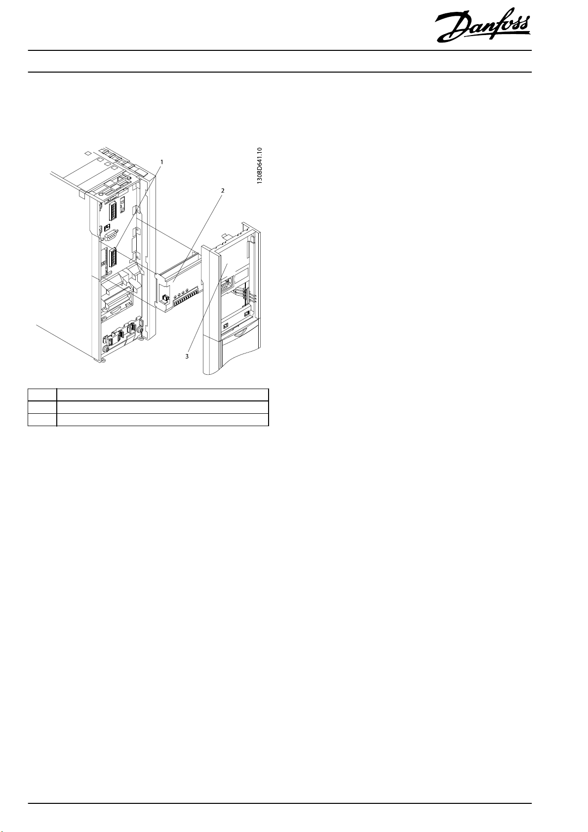
Mounting
Mount the option according to Illustration 1.1.
®
VLT
Encoder Option MCB 102
®
AutomationDrive FC 301/FC 302
VLT
1Slot B
2Option
3LCP frame
Illustration 1.1 Mounting
2
Danfoss A/S © 06/2017 All rights reserved. MI33F402
Page 3

®
VLT
Installation Instructions
Encoder Option MCB 102
®
AutomationDrive FC 301/FC 302
VLT
Electrical Installation
NOTICE
Supply the encoder through the VLT® Encoder Option MCB 102. Avoid using external supply for the encoder.
Encoder monitor
The 4 encoder channels (A, B, Z, and D) are monitored, open, and short circuits can be detected. There is a green LED for each
channel which lights up when the channel is OK.
NOTICE
To view the LEDs on the option, remove the cover. Select response to encoder errors in parameter 17-61 Feedback Signal
Monitoring.
NOTICE
Maximum cable length for incremental encoder 150 m [492 ft].
Connector
designation
X31
1 – – – – 24 V output (21–25 V, I
2–
3
4 GND GND GND GND GND
5 A input A input A input A input A input
6 A inv input A inv input A inv input A inv input A inv input
7 B input B input B input B input B input
8 B inv input B inv input B inv input B inv input B inv input
9 Z input +Data RS485 Clock out Clock out Z input OR +Data RS485 OR clock
10 Z inv input -Data RS485 Clock out inv. Clock out inv. Z input OR -Data RS485 OR clock-
11 NC NC Data in Data in Data
12 NC NC Data in inv. Data in inv. Data-
Maximum 5 V on X31.5-12
Table 1.5 Encoder Connections
1) Typical supply voltage for the encoder: Check encoder data.
Incremental
(TTL and SinCos)
1)
5 V
Hiperface
8 V
–
®
1)
EnDat SSI Description
– – 8 V output (7–12 V, I
5 V
1)
5 V
1)
5 V output (5 V ±5%, I
max
: 200 mA)
max
max
: 125 mA)
: 200 mA)
MI33F402 Danfoss A/S © 06/2017 All rights reserved.
3
Page 4

Installation Instructions
Set-up and Connection
®
VLT
Encoder Option MCB 102
®
AutomationDrive FC 301/FC 302
VLT
VLT® AutomationDrive FC 301/FC 302 with VLT® Encoder Option MCB 102 supports multiple encoder
congurations
which can be
used as speed and/or position feedback for closed-loop ux motor control, closed-loop speed control, and closed-loop position
control:
Select [2] MCB 102 as “Flux Motor Feedback Source” in parameter 1-02 Flux Motor Feedback Source.
•
Select [0] Motor feedb. P1-02 or [2] MCB 102 as “Speed PID Feedback Source” in parameter 7-00 Speed PID Feedback Source.
•
Select [0] Motor feedb. P1-02 or [2] MCB 102 as “Position PI Feedback Source” in parameter 7-90 Position PI Feedback Source
•
Incremental Encoders
With TTL and SinCos Incremental encoder, the actual position is 0 after power-up and encoder pulses are counted to increment/
decrement actual position. For improved resolution with TTL encoders, both the positive and negative edges of A and B pulses are
detected giving 4 quad counts per encoder pulse. With SinCos encoders, the signal is sampled 1024 times per sine-cosine period
meaning that the resulting resolution is 1024 times periods per revolution.
Connection Parameter Description
Parameter 17-10 Signal Type Select the signal type for the encoder:
[1] RS 422 (5V TTL)
[2] Sinusoidal 1Vpp
Parameter 17-11 Resolution
(PPR)
Parameter 17-60 Feedback
Direction
Parameter 17-61 Feedback
Signal Monitoring
Illustration 1.2 Incremental Encoder
Parameter groups 4-3* Motor
Speed Monitoring and 4-4*
Speed Monitoring
Set the resolution of the encoder. Pulses per
revolution for TTL or periods per revolution for
SinCos.
Select [1] Counter clockwise if actual position
(parameter 16-06 Actual Position) counts
negative when the frequency converter is
running forward. Alternative is to swap A and B
track on the encoder connection.
The signal level is monitored by hardware when
using TTL encoders. Select the reaction when a
problem is detected:
[0] Disabled = No reaction
[1] Warning = Warning 90, Feedback monitor is
issued when the signal level is too high or too
low.
[2] Trip = The frequency converter trips with
alarm 90, Feedback monitor when the signal
level is too high or too low. There is no
hardware monitoring of SinCos encoders.
Oer possibility to activate and adjust further
monitoring of speed tracking.
4
Danfoss A/S © 06/2017 All rights reserved. MI33F402
Page 5

®
VLT
Installation Instructions
Encoder Option MCB 102
®
AutomationDrive FC 301/FC 302
VLT
SSI Encoders
Absolute position is read from the encoder and used to set the actual position after power-up. Thereafter, the absolute position is
read every 1 ms and used to track any movements. If the absolute position read from the encoder changes more than half an
encoder revolution from the previous position, it is considered to be invalid and the position value is not used. Up to 4 consecutive
invalid positions are skipped, 5 consecutive invalid positions trigger an error, the reaction to this error depends on the setting of
parameter 17-61 Feedback Signal Monitoring. If no reaction or only warning is selected, up to 10 consecutive invalid positions are
skipped where after the position is considered valid and thus used.
When an incremental track is added, it is used for tracking movements while the absolute position readings are used to monitor,
and if needed, correct any deviations between the 2 tracks. A warning is issued when the actual position based on the incremental
track deviates more than 3 qc from the absolute position.
Connection Parameter Description
Parameter 17-10 Signal Type Select the incremental signal type for the
encoder:
[0] None = no incremental track
[1] RS 422 (5V TTL)
[2] Sinusoidal 1Vpp
Parameter 17-11 Resolution
(PPR)
Parameter 17-20 Protocol
Selection
Parameter 17-21 Resolution
(Positions/Rev)
Parameter 17-22 Multiturn
Revolutions
Parameter 17-24 SSI Data
Lengt h
Parameter 17-25 Clock Rate Set the frequency for the clock signal
Illustration 1.2 SSI Absolute only
Parameter 17-26 SSI Data
Form at
Parameter 17-60 Feedback
Direction
Parameter 17-61 Feedback
Signal Monitoring
Illustration 1.2 SSI Absolute and Incremental
Parameter groups 4-3* Motor
Speed Monitoring and 4-4*
Speed Monitoring
Set the incremental resolution of the encoder.
Pulses per revolution for TTL or periods per
revolution for SinCos.
Select [4] SSI
Set the absolute resolution in positions per
revolution.
Set number of multi turn revolutions.
Set the data length for the absolute position in
number of bits.
®
generated by the VLT
102. Default is 260 kHz. It should be reduced in
case of long encoder cable or electrical noise
issues.
Select the SSI data format:
[0] Gray code
[1] Binary code
Select [1] Counter clockwise if the actual
position (parameter 16-06 Actual Position)
counts negative when the frequency converter
is running forward.
The signal level is monitored by hardware
when using TTL encoders. Select the reaction
when a problem is detected:
[0] Disabled = No reaction
[1] Warning = Warning 90, Feedback monitor is
issued when the signal level is too high or too
low.
[2] Trip = The frequency converter trips with
alarm 90, Feedback monitor when the signal
level is too high or too low. There is no
hardware monitoring of SinCos encoders.
Oer possibility to activate and adjust further
monitoring of speed tracking.
Encoder Option MCB
MI33F402 Danfoss A/S © 06/2017 All rights reserved.
5
Page 6

®
VLT
Installation Instructions
Encoder Option MCB 102
®
AutomationDrive FC 301/FC 302
VLT
Hiperface Encoders
Absolute position is read from the encoder and used to set the actual position after power-up. Thereafter, the incremental track is
used for tracking movements while the absolute position readings are used to monitor and if needed correct any deviations
between the 2 tracks. A warning is issued when the actual position based on the incremental track deviates more than 3 qc from
the absolute position.
Connection Parameter Description
Parameter 17-10 Signal Type Select [2] Sinusoidal 1Vpp
Parameter 17-11 Resolution (PPR) Set the incremental resolution of the
encoder in sine – cosine periods per
revolution.
Parameter 17-20 Protocol
Selection
Parameter 17-21 Resolution
(Positions/Rev)
Parameter 17-22 Multiturn
Revolutions
Parameter 17-34 HIPERFACE
Baudrate
Parameter 17-60 Feedback
Direction
Parameter groups 4-3* Motor
Speed Monitoring and 4-4*
Speed Monitoring
Select [1] HIPERFACE
Set the absolute resolution in positions per
revolution.
Set number of multi turn revolutions.
Set the baud rate for the Hiperface data
channel. Default is 9600 and there is
normally no reason to change it.
Select [1] Counter clockwise if actual position
(parameter 16-06 Actual Position) counts
negative when the frequency converter is
running forward.
Oers possibility to activate and adjust
further monitoring of speed tracking.
6
Danfoss A/S © 06/2017 All rights reserved. MI33F402
Page 7

®
VLT
Installation Instructions
Encoder Option MCB 102
®
AutomationDrive FC 301/FC 302
VLT
EnDat Encoders
Absolute only
Absolute position is read from the encoder and used to set the actual position after power-up. Thereafter, the absolute position is
read every 1 ms and used to track any movements.
Absolute and incremental
Absolute position is read from the encoder and used to set the actual position after power-up. Thereafter, the incremental track Is
used for tracking movements while the absolute position readings are used to monitor, and if needed, correct any deviations
between the 2 tracks. A warning is issued when the actual position based on the incremental track deviates more than 3 qc from
the absolute position.
Connection Parameter Description
Parameter 17-10 Signal Type Select the incremental signal type for the
encoder:
[0] None = no incremental track
[1] RS 422 (5V TTL)
[2] Sinusoidal 1Vpp
Illustration 1.2 EnDat Absolute
Parameter 17-11 Resolution
(PPR)
Parameter 17-20 Protocol
Selection
Parameter 17-22 Multiturn
Revolutions
Parameter 17-25 Clock Rate Set the frequency for the clock signal
Parameter 17-60 Feedback
Direction
Parameter 17-61 Feedback
Signal Monitoring
Parameter groups 4-3* Motor
Speed Monitoring and 4-4*
Speed Monitoring
Set the resolution of the encoder. Pulses per
revolution for TTL or periods per revolution for
SinCos.
Select [2] EnDat
Set number of multi turn revolutions.
®
generated by the VLT
102. Default is 260 kHz. It should be reduced in
case of long encoder cable or electrical noise
issues.
Select [1] Counter clockwise if the actual
position (parameter 16-06 Actual Position) counts
negative when the frequency converter is
running forward.
The signal level is monitored by hardware when
using TTL encoders. Select the reaction when a
problem is detected:
[0] Disabled = No reaction.
[1] Warning = Warning 90, Feedback monitor is
issued when the signal level is too high or too
low.
[2] Alarm = The frequency converter trips with
alarm 90, Feedback monitor when the signal
level is too high or too low. There is no
hardware monitoring of SinCos encoders.
Oer possibility to activate and adjust further
monitoring of speed tracking.
Encoder Option MCB
Illustration 1.2 EnDat Absolute and Incremental
MI33F402 Danfoss A/S © 06/2017 All rights reserved.
7
Page 8

Danfoss can accept no responsibility for possible errors in catalogues, brochures and other printed material. Danfoss reserves the right to alter its products without notice. This also applies to products already on
order provided that such alterations can be made without subsequential changes being necessary in specifications already agreed. All trademarks in this mate rial are property of the respective companies. Danfoss
and the Danfoss logotype are trademarks of Danfoss A/S. All rights reserved.
Danfoss A/S
Ulsnaes 1
DK-6300 Graasten
vlt-drives.danfoss.com
MI33F402130R0309 06/2017
*MI33F402*
 Loading...