

Page 1
MAKING MODERN LIVING POSSIBLE
Parts Manual
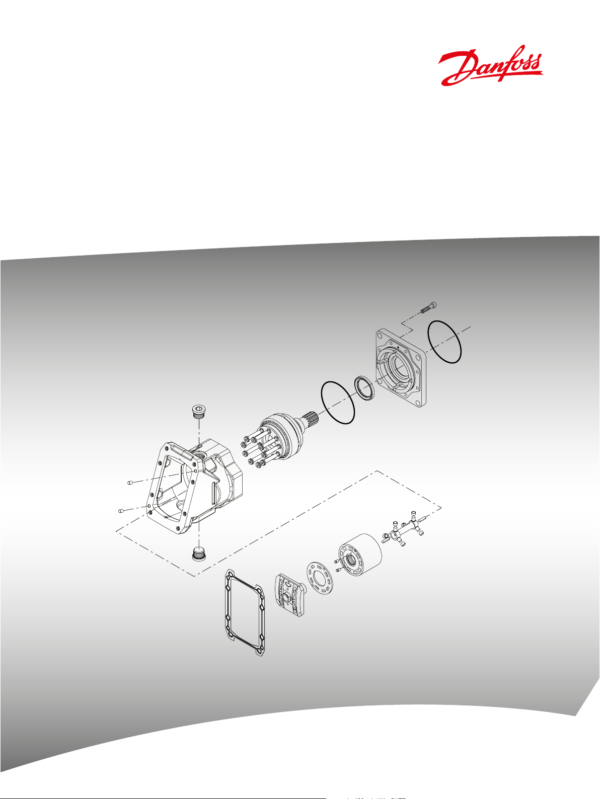
Variable Displacement Motors
Series 51, 160cc
powersolutions.danfoss.com
Page 2

Parts Manual Series 51 160cc Variable Displacement Motor
Contents
General Information
Order code
Cartridge ange
DIN ange
SAE ange
Maximum displacement
End cap
Threshold/range
Service parts identication ............................................................................................................................................. 5
Nameplate ............................................................................................................................................................................5
Date code ..............................................................................................................................................................................6
Service bulletins..................................................................................................................................................................6
Procedure to identify a part ............................................................................................................................................6
Order code ............................................................................................................................................................................7
Common parts ................................................................................................................................................................8-9
Special hardware ......................................................................................................................................................... 8-11
Common parts ...........................................................................................................................................................12-13
Special hardware .......................................................................................................................................................12-15
Common parts ...........................................................................................................................................................16-17
Special hardware .......................................................................................................................................................16-29
Maximum displacement common parts ..........................................................................................................30-31
Maximum displacement ......................................................................................................................................... 30-31
End cap..........................................................................................................................................................................32-41
Threshold/range ........................................................................................................................................................42-43
Charge relief
Output shaft
Control
Charge relief ................................................................................................................................................................44-47
Shaft ............................................................................................................................................................................... 46-47
Electric proportional (A7, D7 and D8) ................................................................................................................ 48-51
Electric proportional (DA and DC)....................................................................................................................... 52-53
Electric 2-position (E1, E2 and E8) ....................................................................................................................... 54-55
Electric proportional (ED and EE) ........................................................................................................................ 56-57
Electric proportional with protective cover (EF) ............................................................................................ 58-59
Electric proportional (EP, EQ, ER, and ES) .......................................................................................................... 60-61
Electric 2-position (F1 and F2) .............................................................................................................................. 62-63
Hydraulic porportional with electric override (H1 and H2) ....................................................................... 64-65
Electric proportional w/pressure reducing (H3 and H4) ............................................................................. 66-67
Hydraulic proportional (HA, HB, HE, HP, HS and HZ) ....................................................................................68-71
Hydraulic porportional with electric override (J3 and J4) .......................................................................... 72-73
Hydraulic proportional (JA and JS) ..................................................................................................................... 74-77
Hydraulic porportional with electric override (K1 and K2) ........................................................................78-79
Electric proportional (L1, L2, L3, L4, L7 and L8) .............................................................................................. 80-81
Hydraulic 2-position (N2)........................................................................................................................................82-83
Pressure compensator (PC and PD) ....................................................................................................................84-87
Electric 2-position (T1, T2, T3 and T4) .................................................................................................................88-91
Pressure compensator (TA) .................................................................................................................................... 92-93
Hydraulic 2-position (TH) ....................................................................................................................................... 92-93
Electric 2-position (TM, TN, TP, TW, U3, U4, Y3, Y8, YA and YB) ...................................................................92-97
2
520L0768 • Rev CA • September 2014
Page 3

Parts Manual Series 51 160cc Variable Displacement Motor
Contents
Servo supply
Loop ushing system
Control ramp
Orice
Minimum displacement
Pcor adjuster
Overhaul seal kit
Service bulletins
Servo pressure supply .......................................................................................................................................... 98-109
Loop ushing ......................................................................................................................................................... 110-111
Control ramp ..........................................................................................................................................................112-113
Orice .......................................................................................................................................................................114-135
Minimum displacement ..................................................................................................................................... 136-137
PCOR adjuster ........................................................................................................................................................136-137
Overhaul seal kit ................................................................................................................................................... 138-139
SB-1993-006 (end cap gasket) .................................................................................................................................. 140
SB-1995-013 (threshold adjustment screw) ........................................................................................................141
SB-1996-005 (end cap and valve segment) ................................................................................................142-143
SB-1997-009 (servo piston seal ring) ...................................................................................................................... 144
SB-1997-030 (valve segment) ...................................................................................................................................145
SB-1999-059 (thread change on DIN shaft assemblies) .................................................................................. 146
SB-2000-044 (loop ushing spring and spring seat change) ........................................................................ 147
SB-2000-049 (incorporate speed sensor in cartridge motors) ...................................................................... 148
SB-2001-015 (synch shaft kit) ....................................................................................................................................149
SB-2002-001 (end cap/control interface seal) ............................................................................................ 150-151
SB-2004-004 (end cap gasket) .................................................................................................................................. 152
SB-2004-013 (shaft seal) ..............................................................................................................................................153
SB-2012-010 (bearing housing redesign) .............................................................................................................154
520L0768 • Rev CA • September 2014
3
Page 4
Parts Manual Series 51 160cc Variable Displacement Motor
General information
Service parts
indentication
The following information and procedure is used to identify the module group, item number,
manufacture date, part number, and part name of the parts included in the Series 51 160cc
variable displacement motors.
The parts listed include all parts which may be used when performing either “Minor Repairs”,
“Major Repairs” or “Conversions” on the Series 51 160cc motors.
Nameplate Each unit will have a nameplate axed to the
housing. The nameplate will include the following
information.
Model Code
The Danfoss model code completely denes the
specic unit and must be used when ordering parts
to service this product.
Model Number
The Danfoss model number is used by the factory in
manufacturing. On repeat orders, a complete unit
can be ordered by the model number.
Serial Number
The Danfoss serial number is used to identify the
manufacture date and the unit sequence in the
build. The serial number is also used to identify the
units warranty time period.
Model No./Ident No.
Model Code
51V160-R-C8-N-D8-
060-AA-G3-C2-30
Serial No.
N-99-12-12345
Made in Germany
515565
M1-R-J-M4-ADA-
The letter code indicates the location of original
manufacture (assembly). “N” indicates the unit was
originally assembled in Neumuenster, Germany.
The rst number (2 digits) indicates the year of
manufacture. (“01” would indicate the unit was
manufactured in 2001)
The second number (2 digits) indicates the calendar
week of manufacture.
The third number (5 digits) is a sequential number
used to identify a specic unit.
4
520L0768 • Rev CA • September 2014
Page 5
Parts Manual Series 51 160cc Variable Displacement Motor
General information
Date code The date code is dened as the year and week of manufacture. The same item number may list more
Service bulletins A Service Bulletin Number (SB-_ _ _ _ - _ _ _) may follow the “Part Name” of the part you desire. You
Procedure to identify a part General
than one part number. This indicates that there is more than one conguration for that item number.
You will see that there are dierent date codes for the dierent part numbers. Find the date code of
your unit from the nameplate to determine which service part number you need to order.
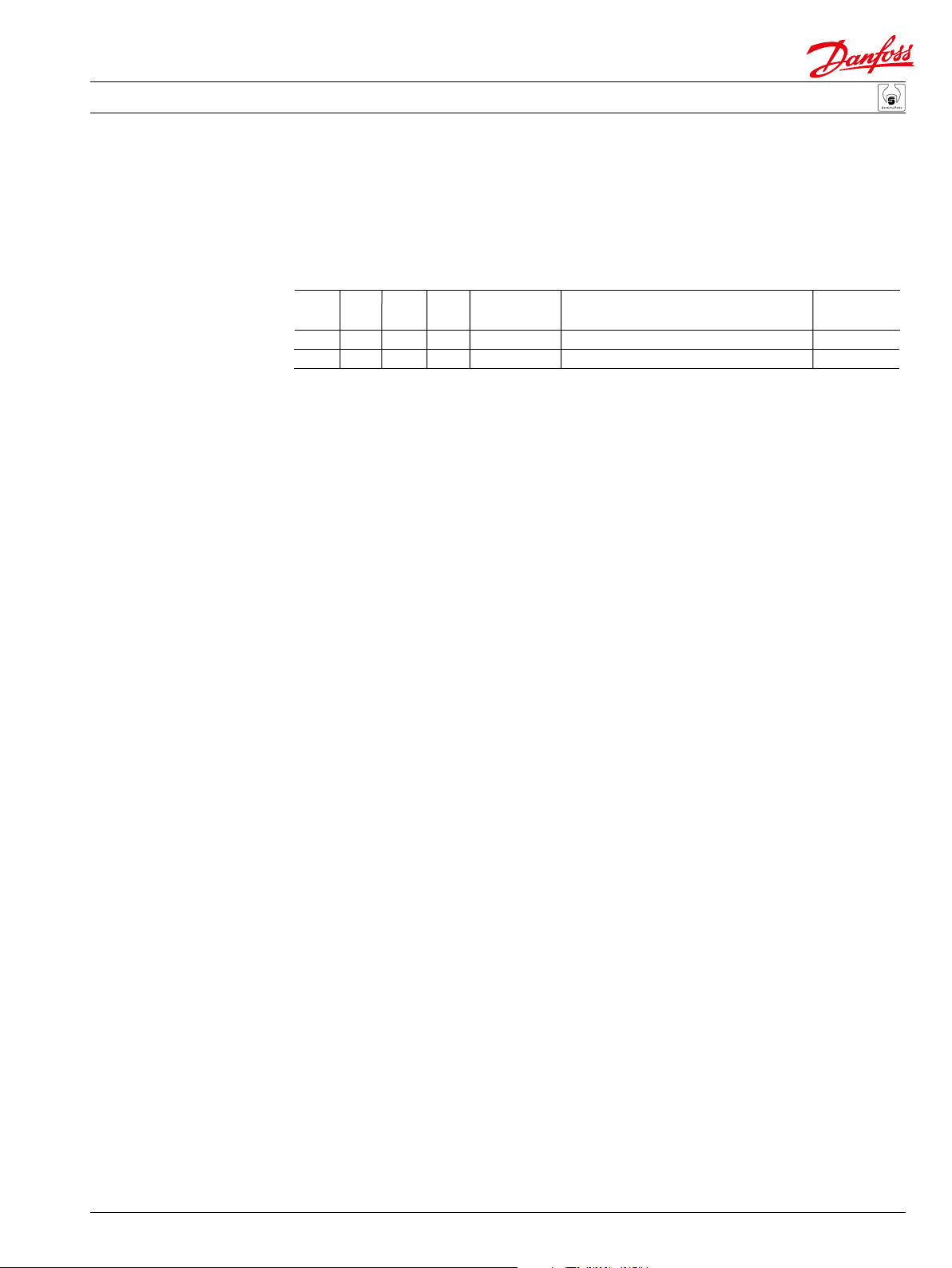
EXAMPLE: The service part desired is Item L035.
Order Date Date
Code Item Begin End Part Number Part Name Usage
C L035 00-25 515752 Bearing housing (SB-2000-049) 1
L035 92-33 00-24 743831 Bearing housing 1
All units using this order code with a date code of 92-33 and up to and including 00-24, must use part
number “743831”. All units with a date code of 00-25 and newer must use part number “515752.”.
must read that Service Bulletin prior to ordering that part. The information contained in these Service
Bulletins, as of the print date of this bulletin, are included at the end of this manual. Service Bulletins
contain more detailed information such as interchangeability, what additional parts are involved, etc.
It is suggested that you add additional Service Bulletins to this manual as you recieve them.
The modular design of Series 51 motors result in a simplied service parts list and part number
identication procedure.
The same item numbers are used for same part names on all units within a product type. (Example:
The lip seal - Item L40, has the same item number on all motors.)
A part number that has another number following it in parentheses is done to make this a world wide
manual. The rst number is sold in Germany. The number in parentheses is sold in the United States.
(Example: 664524 (9005110-9000), customers would order 9005110-9000 if ordering the part in the
United States.)
Example of a part identication
The nameplate on a Series 51 motor has an Order Code of 51V160 R C8 N D8 M1 R J M4 ADA 060 AA
G3 C2 30. Use the following procedures to determine the part number of the drive shaft used on this
motor.
1) Referring to the shaft module in the Order Code (see page 7), the shaft option for this motor is
identied by the code “C8”. (51V160 R C8 N D8 M1 R J M4 ADA 060 AA G3 C2 30)
2) Referring to the Service Parts List, nd the shaft group. Next nd the order code that relates to this
unit, which is “C8”. The shaft is found to be item QL10 and part number 11100431 if a speed ring is not
required. The shaft is found to be item QL11 and part number 11100432 if a speed ring is required.
520L0768 • Rev CA • September 2014
5
Page 6

Parts Manual Series 51 160cc Variable Displacement Motor
Notes
6
520L0768 • Rev CA • September 2014
Page 7
Parts Manual Series 51 160cc Variable Displacement Motor
Pr
F
Fr
End cap
Shaf
Maximum displacemen
Se
Special hardwar
M
L
PC
VZ
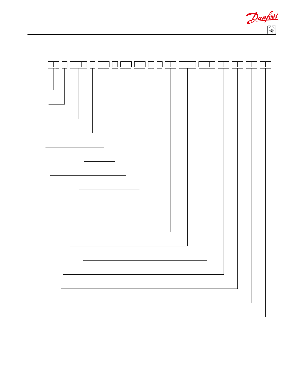
Order code
GL FM NJST WYPK
5 1
V 1 6 0 R
C 8 1 R
D
N
8 M
4
J
A D
A
0 6
4
A A G
C 2 3 0
3M
oduct
lange
ame size
t
Control
rvo pressure supply
Threshold/range
Control ramp
Orifice
t
e
inimum displacement
oop flushing
Charge relief
Threshold setting
OR setting
P100 543E
520L0768 • Rev CA • September 2014
7
Page 8
Parts Manual Series 51 160cc Variable Displacement Motor
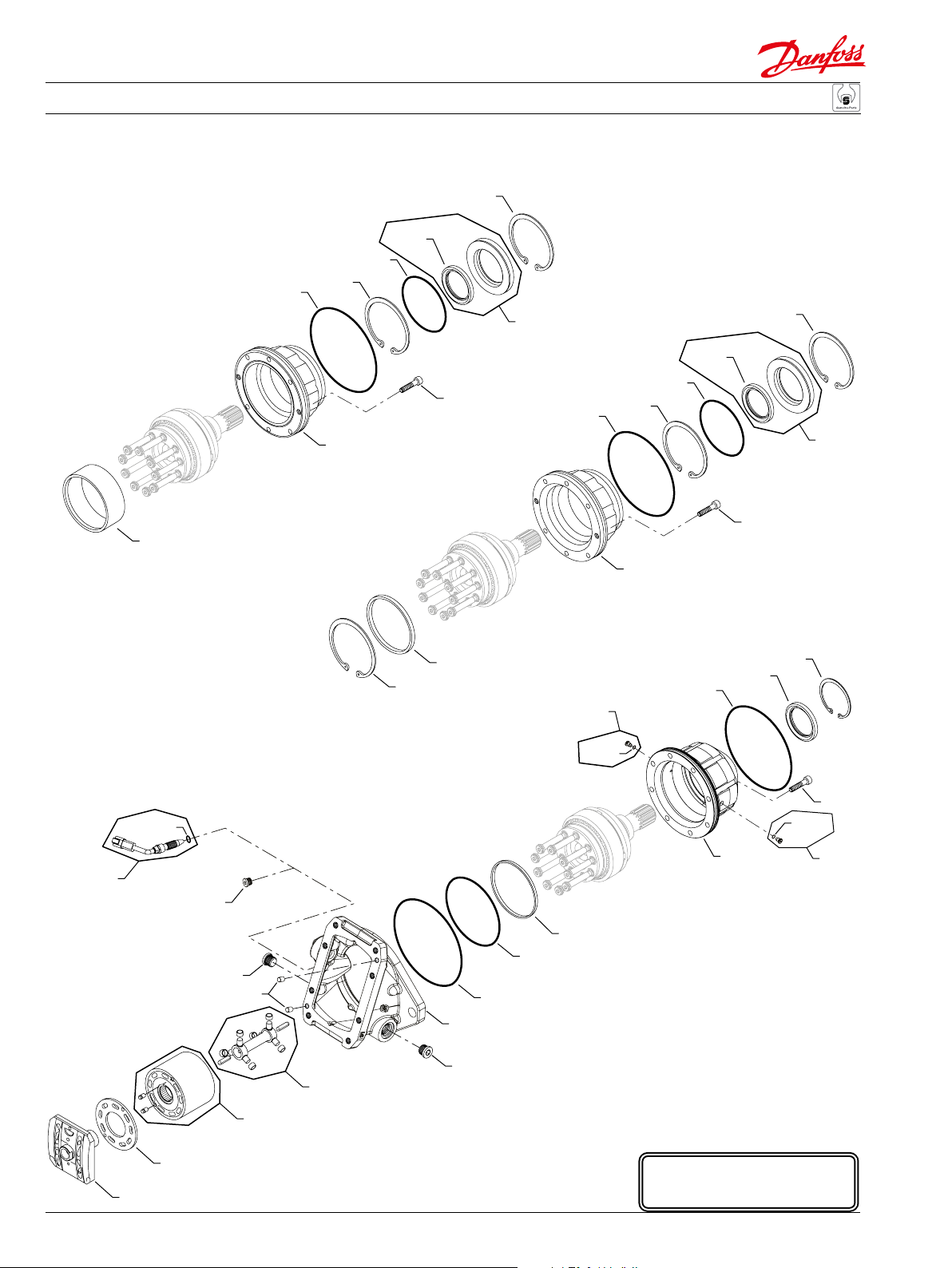
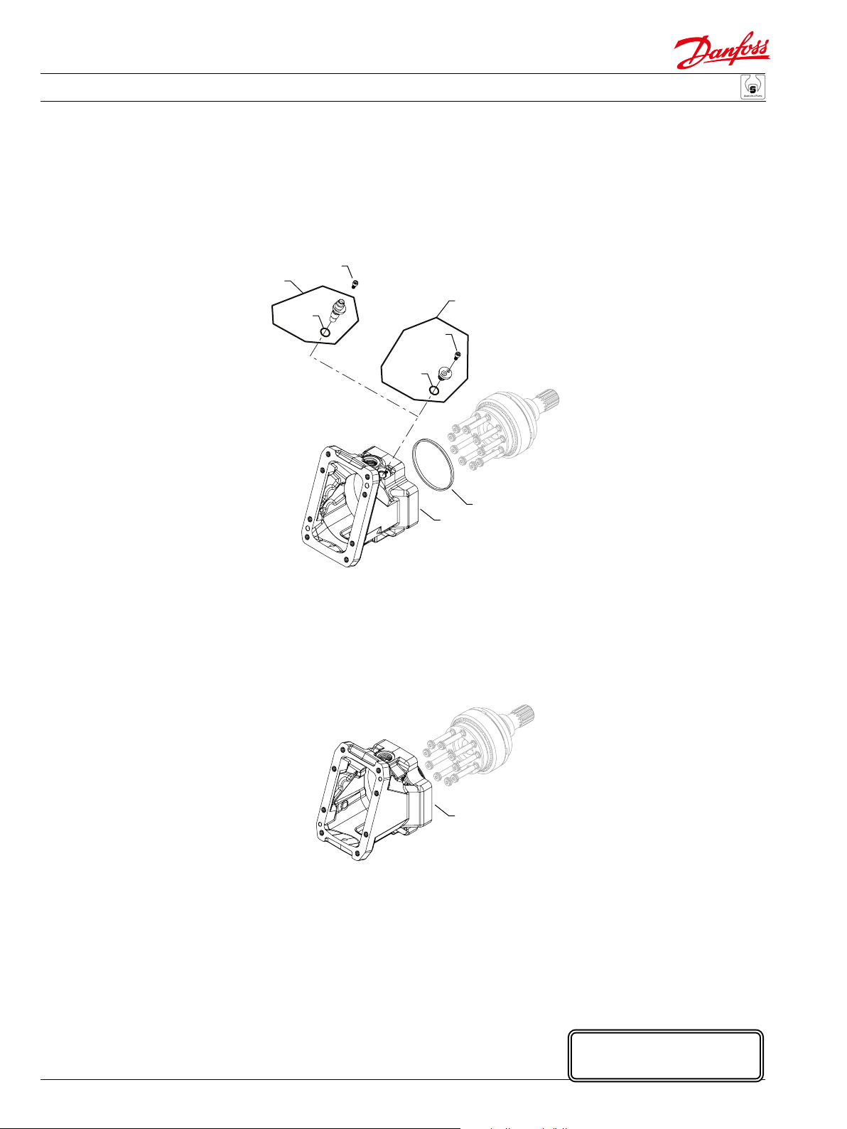
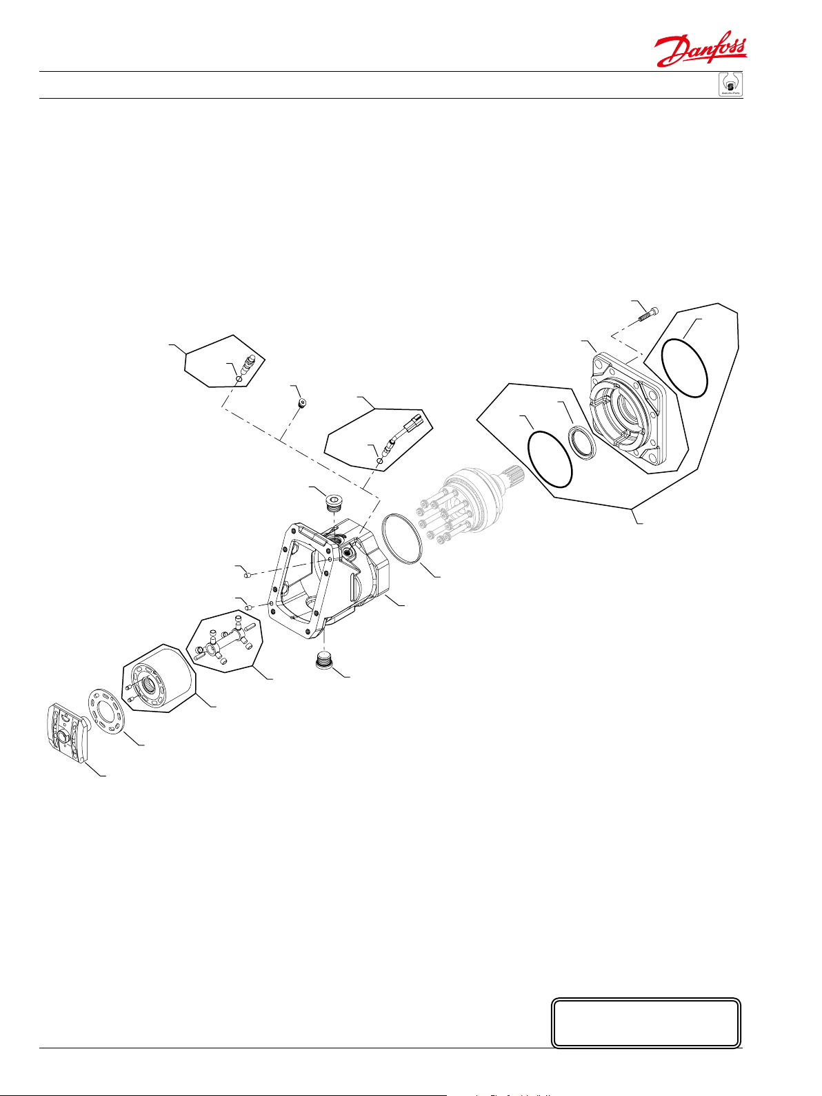
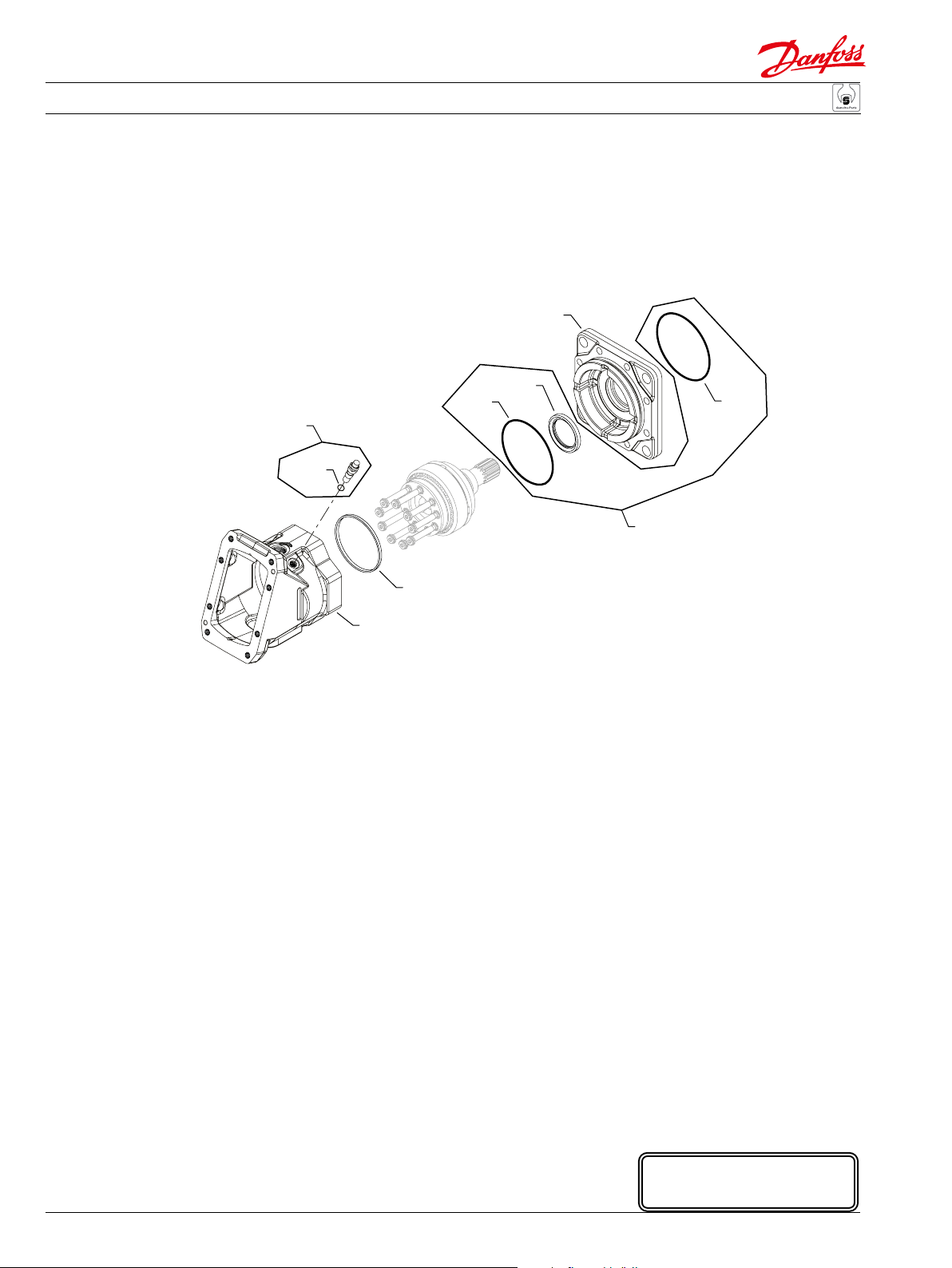
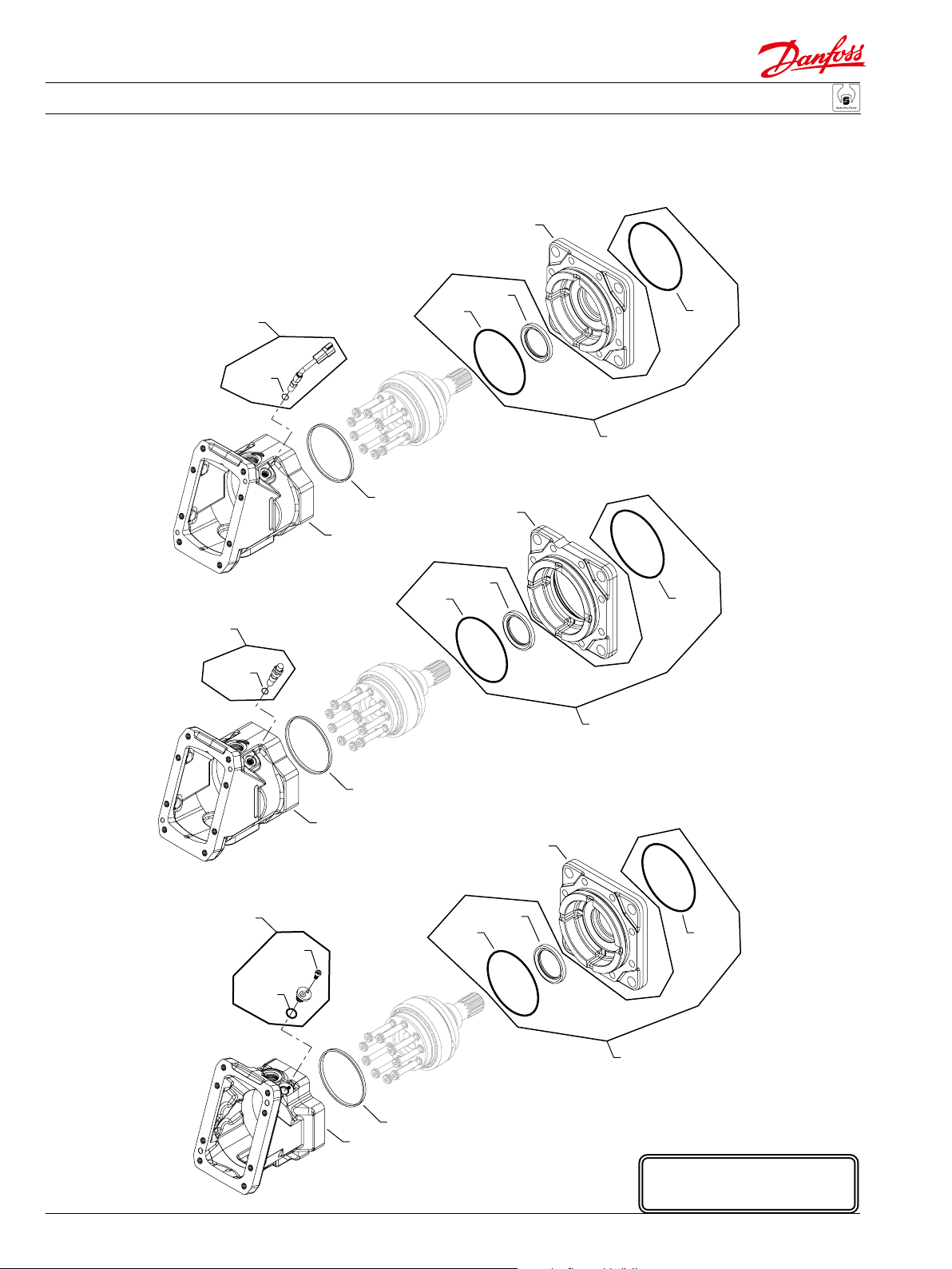
Variable Displacement Motor
L80
*L40
*L50C
L80
L750
L70
*B80C
L035
N-00-25 to
N-12-13
Prior to
N-00-24
L95
*B80C
L80
*L40
*L50C
L80
L750
L70
W30
*QW30
(ACB, ACM,
ACN & ACR)
W30
B70
B50
(ABA)
L81
L95
B10
*L85
*L90
& beyond
L81
*QL81
W10
L035
N-12-14
*B80C
*L40
L035
L80
L70
*QL81
L81
B71
Q020
QC05
E100 327E
C10
B05
8
520L0768 • Rev CA • September 2014
* = included in base motor seal kit Q210
Enlarged bold type item
numbers are recommended
part to stock for servicing.
Page 9

Parts Manual Series 51 160cc Variable Displacement Motor
Variable Displacement Motor
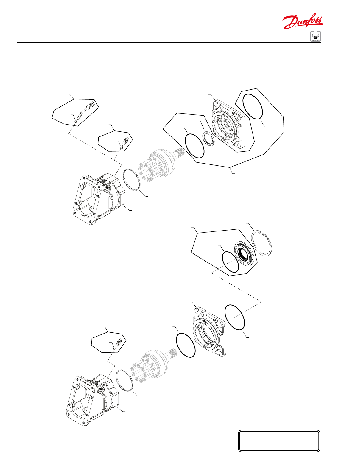
Cartridge ange common parts
Order Date Date Qty. per
code Item begin end Part number Part name model/kit
C B05 92-33 11070148 Valve segment (SB-1996-005 & SB-1997-030) 1
B50 92-33 9004800-3708 Pin 2
B70 92-33 320002 (9005110-9200) Plug assembly 1
B71 92-33 320002 (9005110-9200) Plug assembly 1
B80C 92-33 083659 O-ring 1
C10 92-33 515369 Bearing plate 1
L035 12-14 11038815 Bearing housing (SB-2012-010) 1
L035 00-25 12-13 11009384 Bearing housing (SB-2000-049) 1
L40 05-41 519022 Lip seal (SB-2000-049) 1
L40 92-33 05-40 341735 Lip seal 1
L50C 92-33 056739 (9004104-1580) O-ring 1
L70 92-33 290502 Screw 8
L80 12-14 392423 Retaining ring (SB-2012-010) 1
L80 92-33 12-13 392498 Retaining ring 2
L81 12-14 11056747 Bearing log (SB-2012-010) 2
L81 00-25 12-13 297655 Retaining ring (SB-2000-049) 1
L85 92-33 083659 O-ring 1
L90 00-25 515751 O-ring 1
L90 92-33 00-24 502208 O-ring (SB-2000-049) 1
L95 00-25 12-13 515753 Distance ring 1
L95 92-33 00-24 743898 Distance ring (SB-2000-049) 1
L750 92-33 12-13 510485 Seal carrier assembly (SB-2012-010) 1
Q020 92-33 517310 Synch shaft kit (SB-2001-015) 1
QC05 92-33 356113 Cylinder block assembly 1
QL81 12-14 039297 (9004201-1200) O-ring (SB-2012-010) 2
Special hardware, cartridge ange
ABA B10 99-42 515749 Housing with speed sensor port 1
W10 99-42 11132982 Speed ring 1
W30 99-42 140644 Plug assembly 1
ACB B10 07-23 515749 Housing with speed sensor port 1
QW30 07-23 085043 (9004201-3700) O-ring 1
W10 07-23 11132982 Speed ring 1
W30 07-23 KPPG26408 Speed sensor assembly 1
ACM B10 06-26 515749 Housing with speed sensor port 1
QW30 06-26 085043 (9004201-3700) O-ring 1
W10 06-26 11132982 Speed ring 1
W30 06-26 KPPG29408 Speed sensor assembly 1
ACN B10 06-34 515749 Housing with speed sensor port 1
QW30 06-34 085043 (9004201-3700) O-ring 1
W10 06-34 11132982 Speed ring 1
W30 06-34 KPPG29408 Speed sensor assembly 1
ACR B10 10-46 515749 Housing with speed sensor port 1
QW30 10-46 085043 (9004201-3700) O-ring 1
W10 10-46 11132982 Speed ring 1
W30 10-46 KPPG26408 Speed sensor assembly 1
520L0768 • Rev CA • September 2014
9
Page 10
Parts Manual Series 51 160cc Variable Displacement Motor
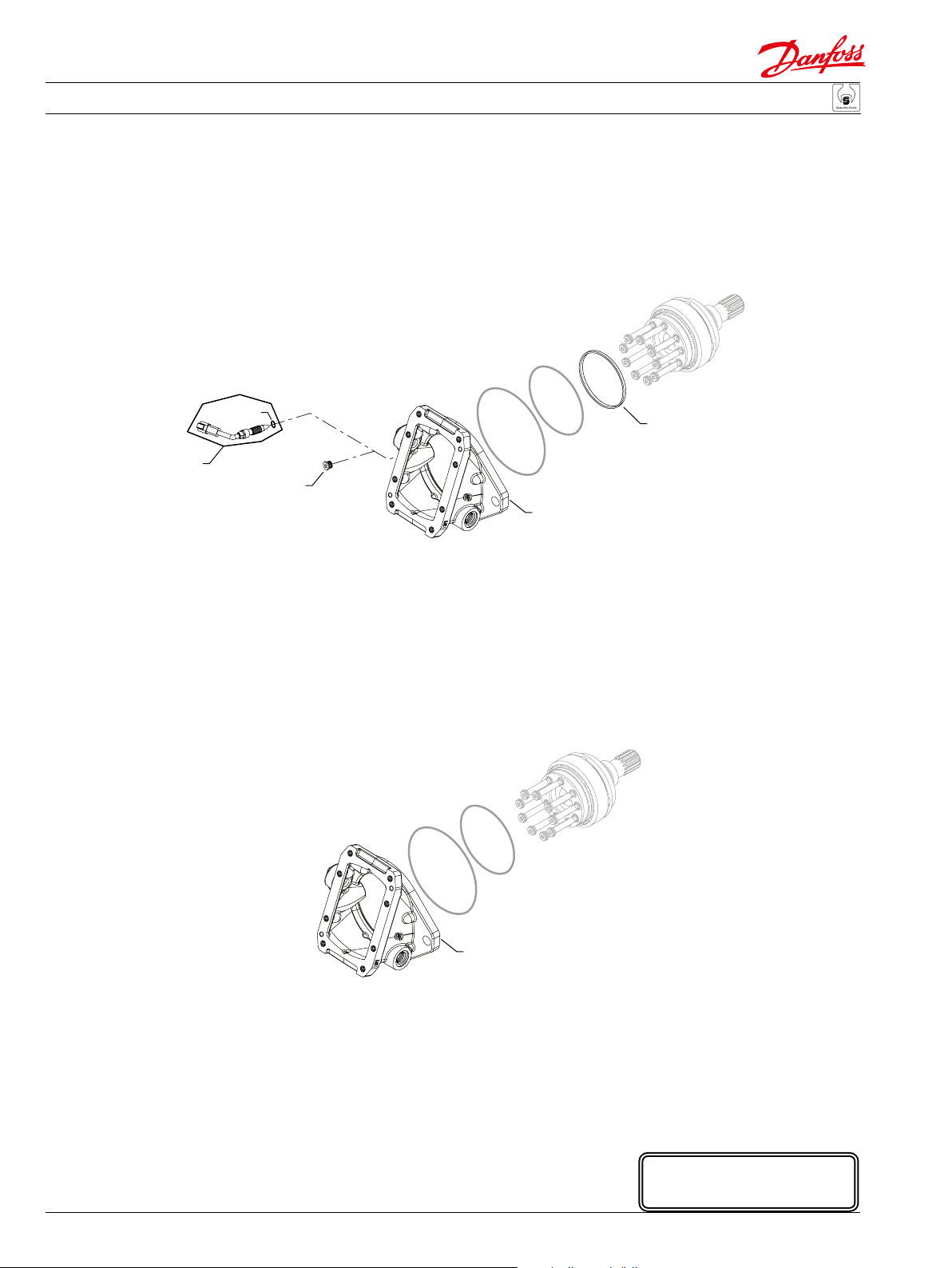
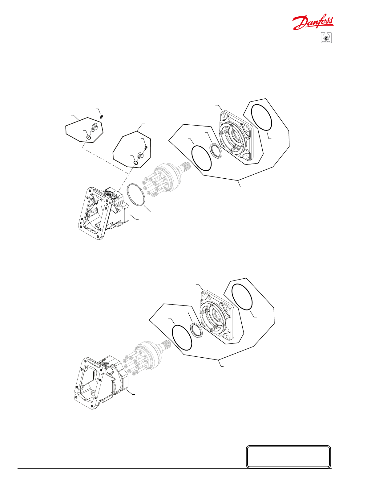
Variable Displacement Motor
(AKB & ANF)
W30
*QW30
W10
W30
B10
(DDA, DDH &
NNN)
B10
E103 151E
Enlarged bold type item
* = included in base motor seal kit Q210
10
520L0768 • Rev CA • September 2014
numbers are recommended
part to stock for servicing.
Page 11
Parts Manual Series 51 160cc Variable Displacement Motor
Variable Displacement Motor
Special hardware, cartridge ange
Order Date Date Qty. per
code Item begin end Part number Part name model/kit
AKB B10 02-38 515749 Housing with speed sensor port 1
W10 02-38 11132982 Speed ring 1
W30 02-38 140644 Plug assembly 1
ANF B10 08-35 515749 Housing with speed sensor port 1
QW30 08-35 085043 (9004201-3700) O-ring 1
W10 08-35 11132982 Speed ring 1
W30 08-35 KPPG26708 Speed sensor assembly 1
DDA B10 08-35 516256 Housing without speed sensor port 1
DDH B10 08-35 516256 Housing without speed sensor port 1
NNN B10 92-33 516256 Housing without speed sensor port 1
520L0768 • Rev CA • September 2014
11
Page 12
Parts Manual Series 51 160cc Variable Displacement Motor
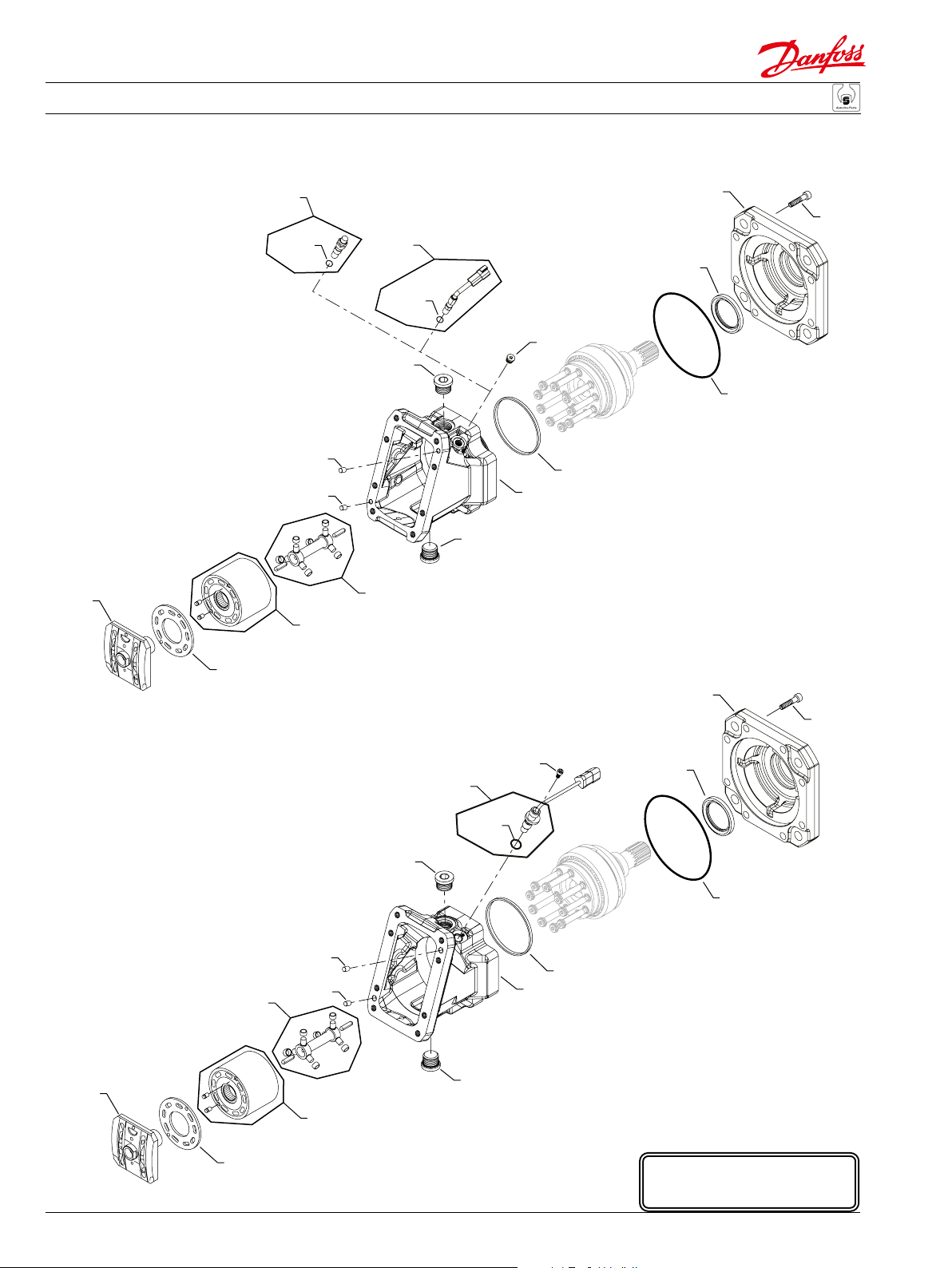
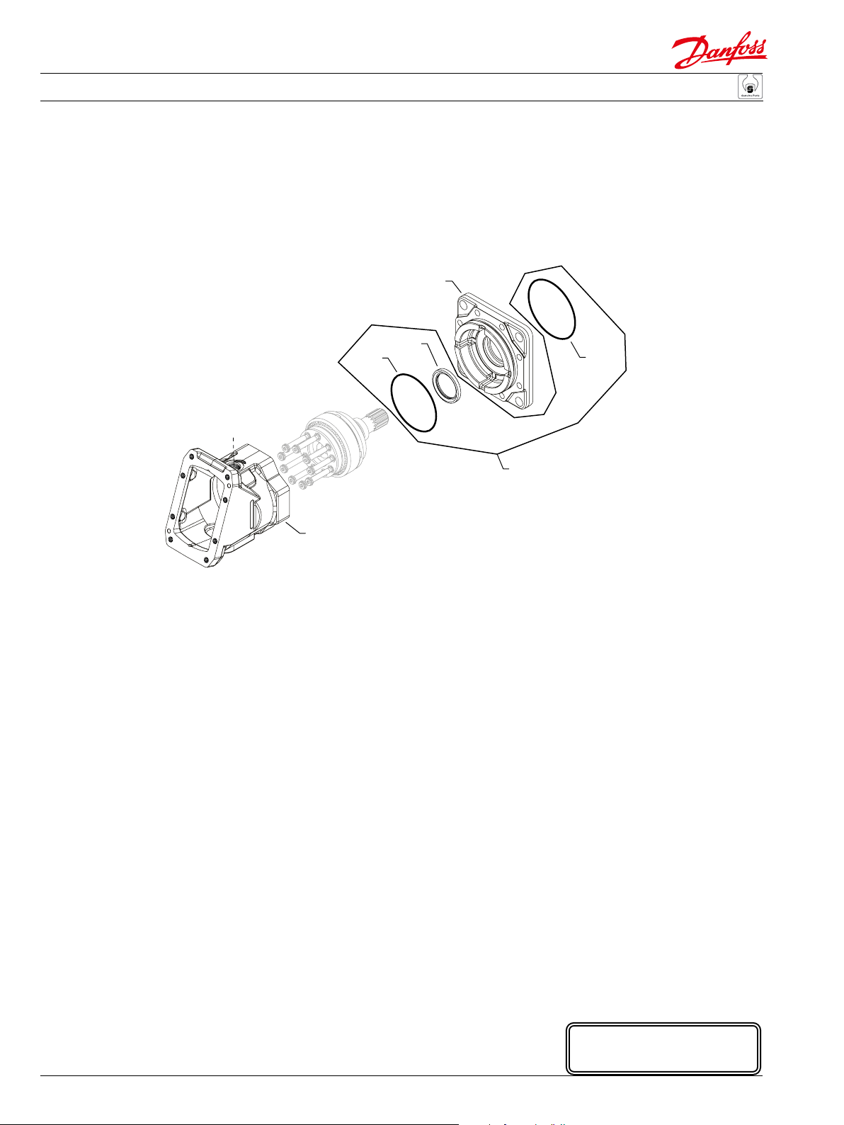
Variable Displacement Motor
B05
W30
*QW30
B50
B50
C05
(ADA)
W30
Q020
*QW30
B70
(ACA, ANA &
ANE)
(ABA &
W30
B10
B71
L35
L70
*L40
AKA)
*L50D
W10
C10
L35
L70
(AMC)
W37
W30
*QW30
B70
Q020
B50
B50
B71
W10
B10
B05
QC05
C10
* = included in base motor seal kit Q210
12
520L0768 • Rev CA • September 2014
*L40
*L50D
E103 152E
Enlarged bold type item
numbers are recommended
part to stock for servicing.
Page 13

Parts Manual Series 51 160cc Variable Displacement Motor
Variable Displacement Motor
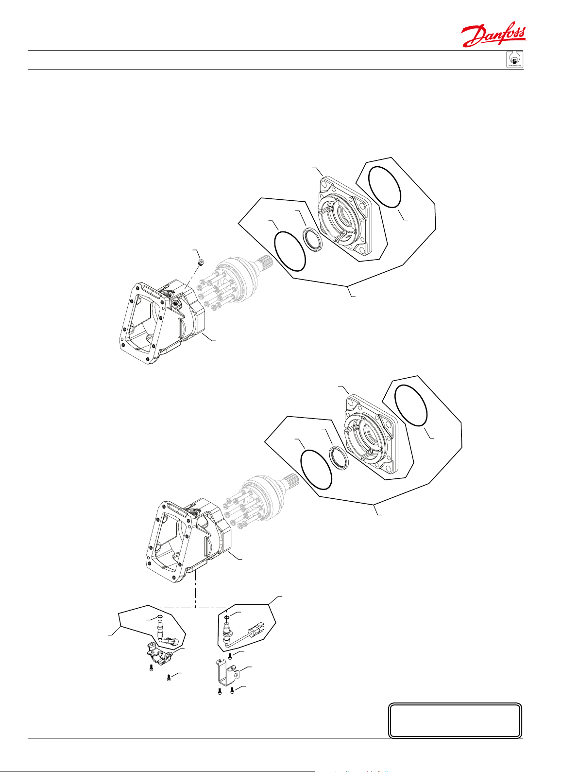
DIN ange common parts
Order Date Date Qty. per
code Item begin end Part number Part name model/kit
D B05 92-01 11070148 Valve segment (SB-1996-005 & SB-1997-030) 1
B50 92-01 9004800-3708 Pin 2
B70 92-01 320002 (9005110-9200) Plug assembly 1
B71 92-01 320002 (9005110-9200) Plug assembly 1
C10 92-01 515369 Bearing plate 1
L35 05-45 520317 Flange, DIN (SB-2004-013) 1
L40 05-45 519022 Lip seal (SB-2004-013) 1
L40 92-01 05-44 341735 Lip seal 1
L50D 92-01 729319 O-ring 1
L70 92-01 290502 Screw 8
Q020 92-01 517310 Synch shaft kit (SB-2001-015) 1
QC05 92-01 356113 Cylinder block assembly 1
Special hardware
ABA B10 92-01 505089 Housing with speed sensor port 1
QW30 92-01 085043 (9004201-3700) O-ring 1
W10 92-01 11132982 Speed ring 1
W30 92-01 140644 Plug assembly 1
ACA B10 07-19 505089 Housing with speed sensor port 1
QW30 07-19 085043 (9004201-3700) O-ring 1
W10 07-19 11132982 Speed ring 1
W30 07-19 KPPG13408 Speed sensor assembly 1
ADA B10 92-01 505089 Housing with speed sensor port 1
QW30 92-01 085043 (9004201-3700) O-ring 1
W10 92-01 11132982 Speed ring 1
W30 92-01 KPPG156 Speed sensor assembly 1
AKA B10 96-38 505089 Housing with speed sensor port 1
QW30 96-38 085043 (9004201-3700) O-ring 1
W10 96-38 11132982 Speed ring 1
W30 96-38 140644 Plug assembly 1
AMC B10 09-49 11004764 Housing with speed sensor port 1
QW30 09-49 085043 (9004201-3700) O-ring 1
W10 09-49 11132982 Speed ring 1
W30 09-49 11051045 Speed sensor assembly 1
W37 09-49 395822 (9007315-0603) Screw 1
ANA B10 09-39 505089 Housing with speed sensor port 1
QW30 09-39 085043 (9004201-3700) O-ring 1
W10 09-39 11132982 Speed ring 1
W30 09-39 KPPG13703 Speed sensor assembly 1
ANE B10 07-22 505089 Housing with speed sensor port 1
QW30 07-22 085043 (9004201-3700) O-ring 1
W10 07-22 11132982 Speed ring 1
W30 07-22 KPPG12704A Speed sensor assembly 1
520L0768 • Rev CA • September 2014
13
Page 14
Parts Manual Series 51 160cc Variable Displacement Motor
Variable Displacement Motor
(AWM)
W37
W30
W30
*QW30
W37
*QW30
(AVA
B10
(CCA & NNN)
W10
B10
E103 153E
Enlarged bold type item
* = included in base motor seal kit Q210
14
520L0768 • Rev CA • September 2014
numbers are recommended
part to stock for servicing.
Page 15
Parts Manual Series 51 160cc Variable Displacement Motor
Variable Displacement Motor
DIN ange common parts
Order Date Date Qty. per
code Item begin end Part number Part name model/kit
AVA B10 03-07 520355 Housing with speed sensor port 1
QW30 03-07 085043 (9004201-3700) O-ring 1
W10 03-07 11132982 Speed ring 1
W30 03-07 520997/P Speed sensor plug assembly 1
W37 03-07 395822 (9007315-0603) Screw 1
AWM B10 05-39 520355 Housing with speed sensor port 1
QW30 05-39 085043 (9004201-3700) O-ring 1
W10 05-39 11132982 Speed ring 1
W30 05-39 KPPG456 Speed sensor assembly 1
W37 05-39 395822 (9007315-0603) Screw 1
CCA B10 04-50 776138 Housing without speed sensor port 1
NNN B10 92-01 776138 Housing without speed sensor port 1
520L0768 • Rev CA • September 2014
15
Page 16
Parts Manual Series 51 160cc Variable Displacement Motor
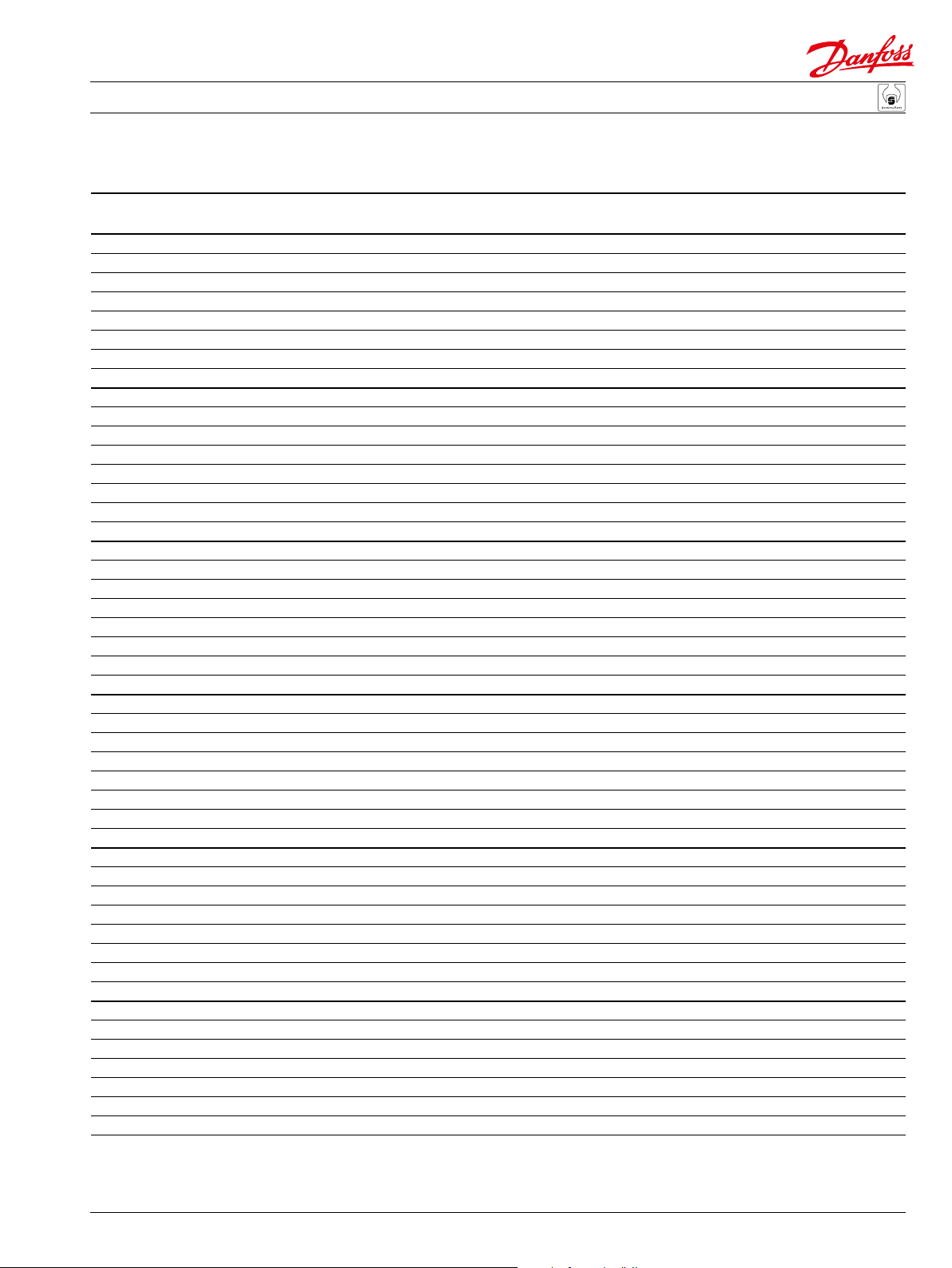
Variable Displacement Motor
(ADA)
W30
*QW30
(ABA)
*W30
W30
*QW30
B70
(AAA, AAC,
ACA, ACB, ACD
& ACP)
*L50V
L70
*B80V
L35
*L40
B05
C10
B50
B50
QC05
Q020
Q010
W10
B10
B71
E103 142E
Enlarged bold type item
* = included in base motor seal kit Q210
16
520L0768 • Rev CA • September 2014
numbers are recommended
part to stock for servicing.
Page 17

Parts Manual Series 51 160cc Variable Displacement Motor
Variable Displacement Motor
SAE ange common parts
Order Date Date Qty. per
code Item begin end Part number Part name model/kit
V B05 92-33 11070148 Valve segment (SB-1996-005 & SB-1997-030) 1
B50 92-33 9004800-3708 Pin 2
B70 92-33 320002 (9005110-9200) Plug assembly 1
B71 92-33 320002 (9005110-9200) Plug assembly 1
B80V 92-33 729285 O-ring 1
C10 92-33 515369 Bearing plate 1
L35 05-45 519417 Flange, SAE (SB-2004-013) 1
L40 05-45 519022 Lip seal (SB-2004-013) 1
L40 92-33 05-44 341735 Lip seal 1
L50V 92-33 726927 O-ring 1
L70 92-33 085183 Screw 8
Q010 92-33 776864 Shaft seal kit 1
Q020 92-33 517310 Synch shaft kit (SB-2001-015) 1
QC05 92-33 356113 Cylinder block assembly 1
Special hardware, SAE ange
AAA & AAC B10 95-42 505087 Housing with speed sensor port 1
QW30 92-33 085043 (9004201-3700) O-ring 1
W10 92-33 11132982 Speed ring 1
W30 92-33 KPPG12508 Speed sensor assembly 1
ABA B10 95-42 505087 Housing with speed sensor port 1
W10 93-35 11132982 Speed ring 1
W30 93-35 140644 Plug assembly 1
ACA B10 95-42 505087 Housing with speed sensor port 1
QW30 94-04 085043 (9004201-3700) O-ring 1
W10 94-04 11132982 Speed ring 1
W30 94-04 KPPG13408 Speed sensor assembly 1
ACB B10 03-23 505087 Housing with speed sensor port 1
QW30 03-23 085043 (9004201-3700) O-ring 1
W10 03-23 11132982 Speed ring 1
W30 03-23 KPPG16408 Speed sensor assembly 1
ACD B10 00-10 505087 Housing with speed sensor port 1
QW30 00-10 085043 (9004201-3700) O-ring 1
W10 00-10 11132982 Speed ring 1
W30 00-10 KPPG17408 Speed sensor assembly 1
ACP B10 06-51 505087 Housing with speed sensor port 1
QW30 06-51 085043 (9004201-3700) O-ring 1
W10 06-51 11132982 Speed ring 1
W30 06-51 KPPG14408 Speed sensor assembly 1
ADA B10 95-42 505087 Housing with speed sensor port 1
QW30 94-12 085043 (9004201-3700) O-ring 1
W10 94-12 11132982 Speed ring 1
W30 94-12 KPPG156 Speed sensor assembly 1
520L0768 • Rev CA • September 2014
17
Page 18
Parts Manual Series 51 160cc Variable Displacement Motor
Variable Displacement Motor
(ADD, ADE, ADK & ADL)
L35
W30
*QW30
B10
W10
*L50V
*L40
*B80V
Q010
E103 157E
Enlarged bold type item
* = included in base motor seal kit Q210
18
520L0768 • Rev CA • September 2014
numbers are recommended
part to stock for servicing.
Page 19
Parts Manual Series 51 160cc Variable Displacement Motor
Variable Displacement Motor
Special hardware, SAE ange
Order Date Date Qty. per
code Item begin end Part number Part name model/kit
ADD B10 99-42 505087 Housing with speed sensor port 1
B80V 99-42 729285 O-ring 1
L35 05-45 519417 Flange, SAE (SB-2004-013) 1
L40 05-45 519022 Lip seal (SB-2004-013) 1
L40 99-42 05-44 341735 Lip seal 1
L50V 99-42 726927 O-ring 1
Q010 99-42 776864 Shaft seal kit 1
QW30 99-42 085043 (9004201-3700) O-ring 1
W10 99-42 11132982 Speed ring 1
W30 99-42 KPPG156 Speed sensor assembly 1
ADE B10 00-34 505087 Housing with speed sensor port 1
B80V 00-34 729285 O-ring 1
L35 05-45 519417 Flange, SAE (SB-2004-013) 1
L40 05-45 519022 Lip seal (SB-2004-013) 1
L40 00-34 05-44 341735 Lip seal 1
L50V 00-34 726927 O-ring 1
Q010 00-34 776864 Shaft seal kit 1
QW30 00-34 085043 (9004201-3700) O-ring 1
W10 00-34 11132982 Speed ring 1
W30 00-34 KPPG156 Speed sensor assembly 1
ADK B10 05-45 505087 Housing with speed sensor port 1
B80V 05-45 729285 O-ring 1
L35 05-45 519417 Flange, SAE (SB-2004-013) 1
L40 05-45 519022 Lip seal (SB-2004-013) 1
L50V 05-45 726927 O-ring 1
Q010 05-45 776864 Shaft seal kit 1
QW30 05-45 085043 (9004201-3700) O-ring 1
W10 05-45 11132982 Speed ring 1
W30 05-45 KPPG156 Speed sensor assembly 1
ADL B10 07-39 505087 Housing with speed sensor port 1
B80V 07-39 729285 O-ring 1
L35 07-39 519417 Flange, SAE 1
L40 07-39 519022 Lip seal 1
L50V 07-39 726927 O-ring 1
Q010 07-39 776864 Shaft seal kit 1
QW30 07-39 085043 (9004201-3700) O-ring 1
W10 07-39 11132982 Speed ring 1
W30 07-39 KPPG156 Speed sensor assembly 1
520L0768 • Rev CA • September 2014
19
Page 20
Parts Manual Series 51 160cc Variable Displacement Motor
Variable Displacement Motor
(ADM &
W30
ADP)
L35
*QW30
W30
*QW30
(AHA)
B10
W10
(ADN)
*L50V
L500
*L40
*B80V
Q010
L600
*L511
20
W30
*QW30
W10
B10
* = included in base motor seal kit Q210
520L0768 • Rev CA • September 2014
L35
*L50V
*B80V
E103 154E
Enlarged bold type item
numbers are recommended
part to stock for servicing.
Page 21
Parts Manual Series 51 160cc Variable Displacement Motor
Variable Displacement Motor
Special hardware, SAE ange
Order Date Date Qty. per
code Item begin end Part number Part name model/kit
ADM B10 08-45 505087 Housing with speed sensor port 1
B80V 08-45 729285 O-ring 1
L35 08-45 519417 Flange, SAE (SB-2004-013) 1
L40 08-45 519022 Lip seal (SB-2004-013) 1
L50V 08-45 726927 O-ring 1
Q010 08-45 776864 Shaft seal kit 1
QW30 08-45 085043 (9004201-3700) O-ring 1
W10 08-45 11132982 Speed ring 1
W30 08-45 KPPG13703 Speed sensor assembly 1
ADN B10 07-29 505087 Housing with speed sensor port 1
B80V 07-29 729285 O-ring 1
L35 07-29 11070161 Flange, SAE 1
L50V 07-29 726927 O-ring 1
L500 07-29 11070155 Seal carrier assembly 1
L511 07-29 11070158 O-ring 1
L600 07-29 11070170 Retaining ring 1
QW30 07-29 085043 (9004201-3700) O-ring 1
W10 07-29 11132982 Speed ring 1
W30 07-29 KPPG156 Speed sensor assembly 1
ADP B10 09-39 505087 Housing with speed sensor port 1
B80V 09-39 729285 O-ring 1
L35 09-39 519417 Flange, SAE 1
L40 09-39 519022 Lip seal (SB-2004-013) 1
L50V 09-39 726927 O-ring 1
Q010 09-39 776864 Shaft seal kit 1
QW30 09-39 085043 (9004201-3700) O-ring 1
W10 09-39 11132982 Speed ring 1
W30 09-39 KPPG12508 Speed sensor assembly 1
AHA B10 02-13 505087 Housing with speed sensor port 1
B80V 02-13 729285 O-ring 1
L35 05-45 519417 Flange, SAE (SB-2004-013) 1
L40 05-45 519022 Lip seal (SB-2004-013) 1
L40 02-13 05-44 341735 Lip seal 1
L50V 02-13 726927 O-ring 1
Q010 02-13 776864 Shaft seal kit 1
QW30 02-13 085043 (9004201-3700) O-ring 1
W30 02-13 KPPG166 Speed sensor assembly 1
520L0768 • Rev CA • September 2014
21
Page 22
Parts Manual Series 51 160cc Variable Displacement Motor
Variable Displacement Motor
(AKB)
L35
W30
B10
*L50V
*L40
*L50V
*B80V
Q010
L35
*L40
*B80V
22
W30
(AMA)
*QW30
B10
*QW30
W35
W36
W37
W35
W36
* = included in base motor seal kit Q210
520L0768 • Rev CA • September 2014
Q010
W30
(AMB & AMD)
E100 651E
Enlarged bold type item
numbers are recommended
part to stock for servicing.
Page 23

Parts Manual Series 51 160cc Variable Displacement Motor
Variable Displacement Motor
Special hardware, SAE ange
Order Date Date Qty. per
code Item begin end Part number Part name model/kit
AKB B10 00-04 505087 Housing with speed sensor port 1
B80V 00-04 729285 O-ring 1
L35 05-45 519417 Flange, SAE (SB-2004-013) 1
L40 05-45 519022 Lip seal (SB-2004-013) 1
L40 00-04 05-44 341735 Lip seal 1
L50V 00-04 726927 O-ring 1
Q010 00-04 776864 Shaft seal kit 1
W10 00-04 11132982 Speed ring 1
W30 00-04 140644 Plug assembly 1
AMA B10 00-33 515847 Housing 1
B80V 00-04 729285 O-ring 1
L35 05-45 519417 Flange, SAE (SB-2004-013) 1
L40 05-45 519022 Lip seal (SB-2004-013) 1
L40 00-04 05-44 341735 Lip seal 1
L50V 00-04 726927 O-ring 1
Q010 00-04 776864 Shaft seal kit 1
QW30 00-33 085043 (9004201-3700) O-ring 1
W10 00-33 11132982 Speed ring 1
W30 00-33 11046858 Speed sensor assembly 1
W35 00-33 8801261 Speed sensor cover 1
W36 00-33 395822 (9007315-0603) Screw 2
AMB B10 00-33 519419 Housing 1
B80V 00-33 729285 O-ring 1
L35 05-45 519417 Flange, SAE (SB-2004-013) 1
L40 05-45 519022 Lip seal (SB-2004-013) 1
L40 00-04 05-44 341735 Lip seal 1
L50V 00-33 726927 O-ring 1
Q010 00-33 776864 Shaft seal kit 1
QW30 00-33 085043 (9004201-3700) O-ring 1
W10 00-33 11132982 Speed ring 1
W30 00-33 11046847 Speed sensor assembly 1
W35 00-33 520021 Speed sensor cover 1
W36 00-33 395822 (9007315-0603) Screw 2
W37 00-33 395822 (9007315-0603) Screw 1
AMD B10 00-33 11098757 Housing 1
B80V 00-33 729285 O-ring 1
L35 05-45 519417 Flange, SAE (SB-2004-013) 1
L40 05-45 519022 Lip seal (SB-2004-013) 1
L40 00-04 05-44 341735 Lip seal 1
L50V 00-33 726927 O-ring 1
Q010 00-33 776864 Shaft seal kit 1
QW30 00-33 085043 (9004201-3700) O-ring 1
W10 00-33 11132982 Speed ring 1
W30 00-33 11100159 Speed sensor assembly 1
W35 00-33 520021 Speed sensor cover 1
W36 00-33 395822 (9007315-0603) Screw 2
W37 00-33 395822 (9007315-0603) Screw 1
520L0768 • Rev CA • September 2014
23
Page 24
Parts Manual Series 51 160cc Variable Displacement Motor
Variable Displacement Motor
W30
*QW30
W30
*QW30
B10
W10
*L50V
*L50V
*L40
*L40
L35
L35
(ANA & ANB)
*B80V
Q010
(APC)
*B80V
Q010
W10
(AVB)
*B80V
W30
*QW30
B10
L35
*L40
*L50V
W37
Q010
W10
B10
* = included in base motor seal kit Q210
24
520L0768 • Rev CA • September 2014
numbers are recommended
part to stock for servicing.
E103 155E
Enlarged bold type item
Page 25

Parts Manual Series 51 160cc Variable Displacement Motor
Variable Displacement Motor
Special hardware, SAE ange
Order Date Date Qty. per
code Item begin end Part number Part name model/kit
ANA B10 01-04 505087 Housing with speed sensor port 1
B80V 01-04 729285 O-ring 1
L35 05-45 519417 Flange, SAE (SB-2004-013) 1
L40 05-45 519022 Lip seal (SB-2004-013) 1
L40 01-04 05-44 341735 Lip seal 1
L50V 01-04 726927 O-ring 1
L70 01-04 085183 Screw 8
Q010 01-04 776864 Shaft seal kit 1
QW30 01-04 085043 (9004201-3700) O-ring 1
W10 01-04 11132982 Speed ring 1
W30 01-04 KPPG13703 Speed sensor 1
ANB B10 01-04 505087 Housing with speed sensor port 1
B80V 01-04 729285 O-ring 1
L35 05-45 519417 Flange, SAE (SB-2004-013) 1
L40 05-45 519022 Lip seal (SB-2004-013) 1
L40 01-04 05-44 341735 Lip seal 1
L50V 01-04 726927 O-ring 1
L70 01-04 085183 Screw 8
Q010 01-04 776864 Shaft seal kit 1
QW30 01-04 085043 (9004201-3700) O-ring 1
W10 01-04 11132982 Speed ring 1
W30 01-04 KPPG16719 Speed sensor assembly 1
APC B10 08-39 505087 Housing with speed sensor port 1
B80V 08-39 729285 O-ring 1
L35 08-39 11051663 Flange, SAE 1
L40 08-39 519022 Lip seal (SB-2004-013) 1
L50V 08-39 726927 O-ring 1
L70 08-39 085183 Screw 8
Q010 08-39 776864 Shaft seal kit 1
QW30 08-39 085043 (9004201-3700) O-ring 1
W10 08-39 11132982 Speed ring 1
W30 08-39 KPPG156 Speed sensor assembly 1
AVB B10 08-35 520358 Housing with speed sensor port 1
B80V 08-35 729285 O-ring 1
L35 08-35 519417 Flange, SAE 1
L40 08-35 519022 Lip seal 1
L50V 08-35 726927 O-ring 1
L70 08-35 085183 Screw 8
Q010 08-35 776864 Shaft seal kit 1
QW30 08-35 085043 (9004201-3700) O-ring 1
W10 08-35 11132982 Speed ring 1
W30 08-35 520997/P Speed sensor plug assembly 1
W37 08-35 395822 (9007315-0603) Screw 1
520L0768 • Rev CA • September 2014
25
Page 26
Parts Manual Series 51 160cc Variable Displacement Motor
Variable Displacement Motor
(AWU)
W30
*QW30
W37
*QW30
W37
(AVC)
W30
B10
*L50V
W10
(CCA, DAA &
DDA)
L35
*L40
*B80V
Q010
26
*L50V
B10
* = included in base motor seal kit Q210
520L0768 • Rev CA • September 2014
L35
*L40
*B80V
Q010
E103 158E
Enlarged bold type item
numbers are recommended
part to stock for servicing.
Page 27

Parts Manual Series 51 160cc Variable Displacement Motor
Variable Displacement Motor
Special hardware, SAE ange
Order Date Date Qty. per
code Item begin end Part number Part name model/kit
AVC B10 10-07 520358 Housing with speed sensor port 1
B80V 10-07 729285 O-ring 1
L35 10-07 519417 Flange, SAE 1
L40 10-07 519022 Lip seal 1
L50V 10-07 726927 O-ring 1
L70 10-07 085183 Screw 8
Q010 10-07 776864 Shaft seal kit 1
QW30 10-07 085043 (9004201-3700) O-ring 1
W10 10-07 11132982 Speed ring 1
W30 10-07 520997/P Speed sensor plug assembly 1
W37 10-07 395822 (9007315-0603) Screw 1
AWU B10 07-34 520358 Housing with speed sensor port 1
B80V 07-34 729285 O-ring 1
L35 07-34 519417 Flange, SAE 1
L40 07-34 519022 Lip seal 1
L50V 07-34 726927 O-ring 1
Q010 07-34 776864 Shaft seal kit 1
QW30 07-34 085043 (9004201-3700) O-ring 1
W10 07-34 11132982 Speed ring 1
W30 07-34 11034658 Speed sensor assembly 1
W37 07-34 395822 (9007315-0603) Screw 1
CCA B10 95-42 356071 Housing without speed sensor port 1
B80V 95-42 729285 O-ring 1
L35 05-45 519417 Flange, SAE (SB-2004-013) 1
L40 05-45 519022 Lip seal (SB-2004-013) 1
L40 95-42 05-44 341735 Lip seal 1
L50V 95-42 726927 O-ring 1
Q010 95-42 776864 Shaft seal kit 1
DAA B10 93-02 356071 Housing without speed sensor port 1
B80V 93-02 729285 O-ring 1
L35 05-45 519417 Flange, SAE (SB-2004-013) 1
L40 05-45 519022 Lip seal (SB-2004-013) 1
L40 93-02 05-44 341735 Lip seal 1
L50V 93-02 726927 O-ring 1
Q010 93-02 776864 Shaft seal kit 1
DDA B10 00-04 356071 Housing without speed sensor port 1
B80V 00-04 729285 O-ring 1
L35 05-45 519417 Flange, SAE (SB-2004-013) 1
L40 05-45 519022 Lip seal (SB-2004-013) 1
L40 00-04 05-44 341735 Lip seal 1
L50V 00-04 726927 O-ring 1
Q010 00-04 776864 Shaft seal kit 1
520L0768 • Rev CA • September 2014
27
Page 28
Parts Manual Series 51 160cc Variable Displacement Motor
Variable Displacement Motor
(CCA, DAA, DDC,
DDE, DDH, DDK,
KAA & NNN)
L35
B10
*L50V
*L40
*B80V
Q010
28
* = included in base motor seal kit Q210
520L0768 • Rev CA • September 2014
E103 156E
Enlarged bold type item
numbers are recommended
part to stock for servicing.
Page 29
Parts Manual Series 51 160cc Variable Displacement Motor
Variable Displacement Motor
Special hardware, SAE ange
Order Date Date Qty. per
code Item begin end Part number Part name model/kit
DDC B10 00-04 356071 Housing without speed sensor port 1
B80V 00-04 729285 O-ring 1
L35 05-45 519417 Flange, SAE (SB-2004-013) 1
L40 05-45 519022 Lip seal (SB-2004-013) 1
L40 00-04 05-44 341735 Lip seal 1
L50V 00-04 726927 O-ring 1
Q010 00-04 776864 Shaft seal kit 1
DDE B10 00-04 356071 Housing without speed sensor port 1
B80V 00-04 729285 O-ring 1
L35 05-45 519417 Flange, SAE (SB-2004-013) 1
L40 05-45 519022 Lip seal (SB-2004-013) 1
L40 00-04 05-44 341735 Lip seal 1
L50V 00-04 726927 O-ring 1
Q010 00-04 776864 Shaft seal kit 1
DDH B10 00-04 356071 Housing without speed sensor port 1
B80V 00-04 729285 O-ring 1
L35 05-45 519417 Flange, SAE (SB-2004-013) 1
L40 05-45 519022 Lip seal (SB-2004-013) 1
L40 00-04 05-44 341735 Lip seal 1
L50V 00-04 726927 O-ring 1
Q010 00-04 776864 Shaft seal kit 1
DDK B10 00-04 356071 Housing without speed sensor port 1
B80V 00-04 729285 O-ring 1
L35 05-45 519417 Flange, SAE (SB-2004-013) 1
L40 05-45 519022 Lip seal (SB-2004-013) 1
L40 00-04 05-44 341735 Lip seal 1
L50V 00-04 726927 O-ring 1
Q010 00-04 776864 Shaft seal kit 1
KAA B10 98-03 511387 Housing without speed sensor port 1
B80V 98-03 729285 O-ring 1
L35 05-45 519417 Flange, SAE (SB-2004-013) 1
L40 05-45 519022 Lip seal (SB-2004-013) 1
L40 98-03 05-44 341735 Lip seal 1
L50V 98-03 726927 O-ring 1
Q010 98-03 776864 Shaft seal kit 1
NNN B10 92-33 356071 Housing without speed sensor port 1
B80V 92-33 729285 O-ring 1
L35 05-45 519417 Flange, SAE (SB-2004-013) 1
L40 05-45 519022 Lip seal (SB-2004-013) 1
L40 98-03 05-44 341735 Lip seal 1
L50V 92-33 726927 O-ring 1
Q010 92-33 776864 Shaft seal kit 1
520L0768 • Rev CA • September 2014
29
Page 30
Parts Manual Series 51 160cc Variable Displacement Motor
Variable Displacement Motor
G110 used
prior to 03-39
G110
F100
F200
*G100
(A, B, C, D & E)
G24
G260
G110 used
prior to 03-39
G110
*G100
(N)
G24
G260
(W)
G24
G110
G260
*G100
30
* = included in base motor seal kit Q210
520L0768 • Rev CA • September 2014
E100 652E
Enlarged bold type item
numbers are recommended
part to stock for servicing.
Page 31

Parts Manual Series 51 160cc Variable Displacement Motor
Variable Displacement Motor
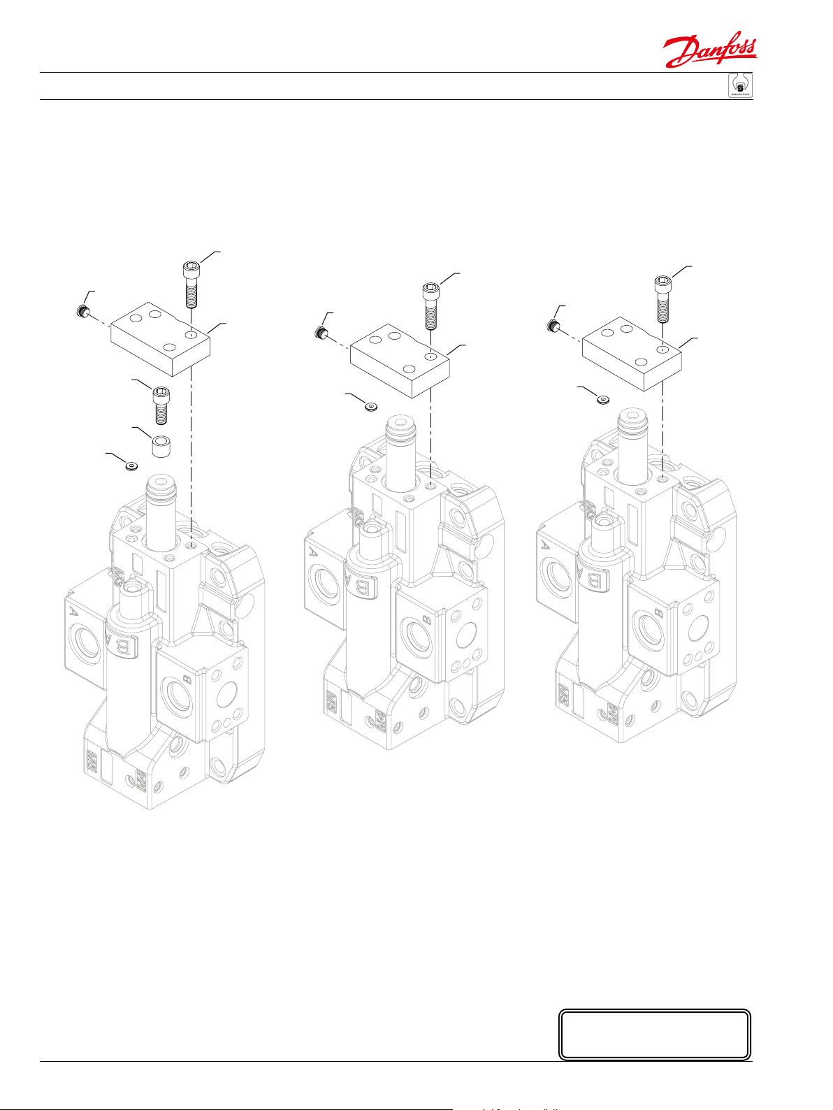
Maximum displacement
Order Date Date Qty. per
code Item begin end Part number Part name model/kit
A F100 95-35 393694 Screw, M10 x 25 mm 1
F200 95-35 672071 Spacer, 4.5 mm 1
G24 95-35 727586 (9007314-1008) Screw 4
G100 95-35 792739 O-ring, rectangular 1
G110 95-35 03-38 11040532 Plug assembly 1
G260 95-35 11000595 Cover 1
B F100 92-33 393702 Screw, M10 x 30 mm 1
F200 92-33 318683 Spacer, 9.0 mm 1
G24 92-33 727586 (9007314-1008) Screw 4
G100 92-33 792739 O-ring, rectangular 1
G110 92-33 03-38 11040532 Plug assembly 1
G260 92-33 11000595 Cover 1
C F100 92-33 727586 Screw, M10 x 35 mm 1
F200 92-33 347088 Spacer, 13.0 mm 1
G24 92-33 727586 (9007314-1008) Screw 4
G100 92-33 792739 O-ring, rectangular 1
G110 92-33 03-38 11040532 Plug assembly 1
G260 92-33 11000595 Cover 1
D F100 98-03 732982 Screw, M10 x 40 mm 1
F200 98-03 306993 Spacer, 17.0 mm 1
G24 98-03 727586 (9007314-1008) Screw 4
G100 98-03 792739 O-ring, rectangular 1
G110 98-03 03-38 11040532 Plug assembly 1
G260 98-03 11000595 Cover 1
E F100 92-33 732982 Screw, M10 x 40 mm 1
F200 92-33 682084 Spacer, 21.0 mm 1
G24 92-33 727586 (9007314-1008) Screw 4
G100 92-33 792739 O-ring, rectangular 1
G110 92-33 03-38 11040532 Plug assembly 1
G260 92-33 11000595 Cover 1
N G24 92-33 727586 (9007314-1008) Screw 4
G100 92-33 792739 O-ring, rectangular 1
G110 92-33 03-38 11040532 Plug assembly 1
G260 92-33 11000595 Cover 1
W G24 03-40 727586 (9007314-1008) Screw 4
G100 03-40 792739 O-ring, rectangular 1
G110 03-40 11040532 Plug assembly 1
G260 03-40 520017 Cover 1
520L0768 • Rev CA • September 2014
31
Page 32

Parts Manual Series 51 160cc Variable Displacement Motor
Variable Displacement Motor
(A)
Prior to 07-20
G34
G32
*G36
*F10
*F11
F120
G32
G12
G12
G12
G30
G18
F24
G30
F26
F28
G50
*G60
G50
G10
G12
G12
G18
G18
E103 159E
Enlarged bold type item
* = included in base motor seal kit Q210
32
520L0768 • Rev CA • September 2014
numbers are recommended
part to stock for servicing.
Page 33

Parts Manual Series 51 160cc Variable Displacement Motor
Variable Displacement Motor
End cap, axial ports
Order Date Date Qty. per
code Item begin end Part number Part name model/kit
A F10 92-01 508134 Servo piston seal ring (SB-1997-009) 1
F11 92-01 504207 O-ring 1
F24 92-01 500999 Feedback lever 1
F26 92-01 396879 Set screw 1
F28 92-01 042465 Set screw 1
F120 92-01 510077 Servo piston assembly 1
G10 07-20 521046 End cap, axial ports (SB-1996-005, SB-2002-001) 1
G12 95-07 140644 Plug assembly 5
G12 92-01 95-06 140644 Plug assembly 7
G18 10-31 11040532 Plug assembly 3
G18 95-07 10-30 11040532 Plug assembly 2
G18 92-01 95-06 092114 (9007712-0604) Set screw 2
G30 92-01 11040532 Plug assembly 2
G32 07-20 914127 (9007314-1213) Screw, M12 x 60 8
G32 92-01 07-19 914143 (9007314-1214) Screw, M12 x 65 4
G34 92-01 07-19 283325 (9007314-1211) Screw, M12 x 50 4
G36 92-01 364976 O-ring 1
G50 92-01 001511 (9005100-4400) Plug assembly 2
G60 92-01 519806 End cap gasket (SB-1993-006, SB-2004-004) 1
520L0768 • Rev CA • September 2014
33
Page 34

Parts Manual Series 51 160cc Variable Displacement Motor
Variable Displacement Motor
G32
G12
G12
G34
G12
Prior to 07-18
G12
G12
F24
(R)
F26
F28
*G36
*F10
*F11
G50
F120
*G60
G50
34
G12
G12
G12W
G12
G18
G30
G12W
G32
* = included in base motor seal kit Q210
520L0768 • Rev CA • September 2014
G30
G10
G12
G18
G18
E103 160E
Enlarged bold type item
numbers are recommended
part to stock for servicing.
Page 35

Parts Manual Series 51 160cc Variable Displacement Motor
Variable Displacement Motor
End cap, side ports
Order Date Date Qty. per
code Item begin end Part number Part name model/kit
R F10 92-01 508134 Servo piston seal ring (SB-1997-009) 1
F11 92-01 504207 O-ring 1
F24 92-01 500999 Feedback lever 1
F26 92-01 396879 Set screw 1
F28 92-01 042465 Set screw 1
F120 92-01 510077 Servo piston assembly 1
G10 07-18 521048 End cap, side ports (SB-1996-005, SB-2002-001) 1
G12 07-18 140644 Plug assembly 3
G12 95-07 07-17 140644 Plug assembly 5
G12 92-01 95-06 140644 Plug assembly 7
G12W 07-18 664524 (9005110-9000) Plug assembly 2
G18 10-31 11040532 Plug assembly 3
G18 95-07 10-30 11040532 Plug assembly 2
G18 92-01 95-06 092114 (9007712-0604) Set screw 2
G30 92-01 11040532 Plug assembly 2
G32 07-18 914127 (9007314-1213) Screw, M12 x 60 8
G32 92-01 07-17 914143 (9007314-1214) Screw, M12 x 65 4
G34 92-01 07-17 283325 (9007314-1211) Screw, M12 x 50 4
G36 92-01 364976 O-ring 1
G50 92-01 001511 (9005100-4400) Plug assembly 2
G60 92-01 519806 End cap gasket (SB-1993-006, SB-2004-004) 1
520L0768 • Rev CA • September 2014
35
Page 36

Parts Manual Series 51 160cc Variable Displacement Motor
Variable Displacement Motor
(U)
Prior to 07-20
G34
G32
*G36
*F10
*F11
F120
G32
G12
G12
G12
G30
G18
F24
G30
F26
F28
G50
*G60
G50
G10
G12
G12
36
* = included in base motor seal kit Q210
520L0768 • Rev CA • September 2014
G18
G18
E103 159E
Enlarged bold type item
numbers are recommended
part to stock for servicing.
Page 37

Parts Manual Series 51 160cc Variable Displacement Motor
Variable Displacement Motor
End cap, axial ports
Order Date Date Qty. per
code Item begin end Part number Part name model/kit
U F10 05-18 508134 Servo piston seal ring 1
F11 05-18 504207 O-ring 1
F24 05-18 500999 Feedback lever 1
F26 05-18 396879 Set screw 1
F28 05-18 042465 Set screw 1
F120 05-18 510077 Servo piston assembly 1
G10 07-20 11001131 End cap, axial ports 1
G12 05-18 140644 Plug assembly 5
G18 10-31 11040532 Plug assembly 3
G18 05-18 10-30 11040532 Plug assembly 2
G30 05-18 11040532 Plug assembly 2
G32 07-20 914127 (9007314-1213) Screw, M12 x 60 8
G32 05-18 07-19 914143 (9007314-1214) Screw, M12 x 65 4
G34 05-18 07-19 283325 (9007314-1211) Screw, M12 x 50 4
G36 05-18 364976 O-ring 1
G50 05-18 001511 (9005100-4400) Plug assembly 2
G60 05-18 519806 End cap gasket 1
520L0768 • Rev CA • September 2014
37
Page 38

Parts Manual Series 51 160cc Variable Displacement Motor
Variable Displacement Motor
G32
G12
G12
G34
G12
Prior to 07-45
G12
G12
F24
(V)
F26
F28
*G36
*F10
*F11
G50
F120
*G60
G50
38
G12
G12
G12W
G12
G18
G30
G12W
G32
* = included in base motor seal kit Q210
520L0768 • Rev CA • September 2014
G30
G10
G12
G18
G18
E103 160E
Enlarged bold type item
numbers are recommended
part to stock for servicing.
Page 39

Parts Manual Series 51 160cc Variable Displacement Motor
Variable Displacement Motor
End cap, side ports
Order Date Date Qty. per
code Item begin end Part number Part name model/kit
V F10 07-27 508134 Servo piston seal ring 1
F11 07-27 504207 O-ring 1
F24 07-27 500999 Feedback lever 1
F26 07-27 396879 Set screw 1
F28 07-27 042465 Set screw 1
F120 07-27 510077 Servo piston assembly 1
G10 07-45 11029620 End cap, side ports 1
G12 07-45 140644 Plug assembly 3
G12 07-27 07-44 140644 Plug assembly 5
G12W 07-45 664524 Plug assembly 2
G18 10-31 11040532 Plug assembly 3
G18 07-27 10-30 11040532 Plug assembly 2
G30 07-27 11040532 Plug assembly 2
G32 07-45 914127 (9007314-1213) Screw, M12 x 60 8
G32 07-27 07-44 914143 (9007314-1214) Screw, M12 x 65 4
G34 07-27 07-44 283325 (9007314-1211) Screw, M12 x 50 4
G36 07-27 364976 O-ring 1
G50 07-27 001511 (9005100-4400) Plug assembly 2
G60 07-27 519806 End cap gasket 1
520L0768 • Rev CA • September 2014
39
Page 40

Parts Manual Series 51 160cc Variable Displacement Motor
Variable Displacement Motor
(Z)
Prior to 07-20
G34
G32
*G36
*F10
*F11
F120
G32
G12
G12
G12
G30
G18
F24
G30
F26
F28
G50
*G60
G50
G10
G12
G12
40
* = included in base motor seal kit Q210
520L0768 • Rev CA • September 2014
G18
G18
E103 159E
Enlarged bold type item
numbers are recommended
part to stock for servicing.
Page 41

Parts Manual Series 51 160cc Variable Displacement Motor
Variable Displacement Motor
End cap, axial ports
Order Date Date Qty. per
code Item begin end Part number Part name model/kit
Z F10 04-07 508134 Servo piston seal ring 1
F11 04-07 504207 O-ring 1
F24 04-07 500999 Feedback lever 1
F26 04-07 396879 Set screw 1
F28 04-07 042465 Set screw 1
F120 04-07 510077 Servo piston assembly 1
G10 07-20 521046 End cap, axial ports (SB-1996-005, SB-2002-001) 1
G12 04-07 140644 Plug assembly 5
G18 10-31 11040532 Plug assembly 3
G18 04-07 10-30 11040532 Plug assembly 2
G30 04-07 11040532 Plug assembly 2
G32 07-20 914127 (9007314-1213) Screw, M12 x 60 8
G32 04-07 07-19 914143 (9007314-1214) Screw, M12 x 65 4
G34 04-07 07-19 283325 (9007314-1211) Screw, M12 x 50 4
G36 04-07 364976 O-ring 1
G50 04-07 001511 (9005100-4400) Plug assembly 2
G60 04-07 519806 End cap gasket (SB-1993-006, SB-2004-004) 1
520L0768 • Rev CA • September 2014
41
Page 42

Parts Manual Series 51 160cc Variable Displacement Motor
Variable Displacement Motor
(A, B, C, D, G, H, J, K, L,
P, R, S, T, V & W)
*J50
(E & M)
J90
J01
J30
J05
J20
E103 136E
Enlarged bold type item
* = included in base motor seal kit Q210
42
520L0768 • Rev CA • September 2014
numbers are recommended
part to stock for servicing.
Page 43

Parts Manual Series 51 160cc Variable Displacement Motor
Variable Displacement Motor
Threshold/range common parts
Order Date Date Qty. per
code Item begin end Part number Part name model/kit
J20 93-34 11036824 Spring seat 1
J30 96-07 507670 Spring seat (SB-1995-013) 1
J50 92-33 732479 (9004105-0100) O-ring 1
J90 96-07 507683 Threshold adjustment screw assembly (SB-1995-013) 1
Threshold/range
A J05 92-33 507638 Spring 1
(2-5 bar)
B J05 92-33 722215 Spring 1
(6-12 bar)
C J05 92-33 722207 Spring 1
(13-30 bar)
D J05 92-33 722207 Spring 1
(20-30 bar)
E J01 92-07 729442 Spring 1
G J05 92-33 722207 Spring 1
(3-5 bar)
H J05 92-33 722207 Spring 1
(6-8 bar)
J J05 92-33 722215 Spring 1
(15-50 mA)
K J05 92-33 722207 Spring 1
(51-85 mA)
L J05 92-33 722215 Spring 1
(110-370 mA)
M J01 92-07 729442 Spring 1
(45-70 mA)
N No parts
(no adjustment)
P J05 11-08 722215 Spring 1
(no adjustment)
R J05 99-35 507638 Spring 1
(320 mA)
S J05 99-35 507638 Spring 1
(640 mA)
T J05 99-35 507638 Spring 1
(220 mA)
V J05 95-35 507638 Spring 1
(220 mA)
W J05 97-41 507638 Spring 1
(440 mA)
520L0768 • Rev CA • September 2014
43
Page 44
Parts Manual Series 51 160cc Variable Displacement Motor
Variable Displacement Motor
(10-99)
QK10
*K50
*K50
*K51
(A0, A3, B0, B3,
C0, N4 & N6)
QK10
*K51
*K50
(E4, E6, F0,
F3, & G0)
QK10
K40
*K52
*K50
(C3)
QK10
44
* = included in base motor seal kit Q210
520L0768 • Rev CA • September 2014
E103 161E
Enlarged bold type item
numbers are recommended
part to stock for servicing.
Page 45

Parts Manual Series 51 160cc Variable Displacement Motor
Variable Displacement Motor
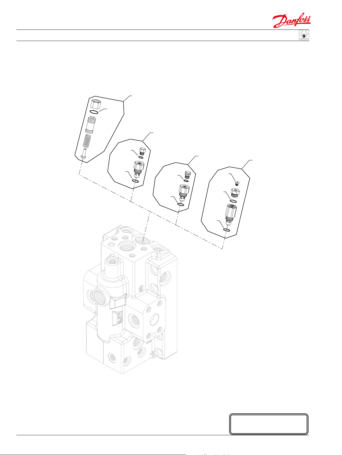
Charge pressure relief
Order Date Date Qty. per
code Item begin end Part number Part name model/kit
00 92-01 01-18 None
10-99 K50 92-01 01-17 001149 (9004201-6200) O-ring 1
QK10 92-01 01-17 8510012 Charge relief valve kit 1
A0 K50 97-25 001149 (9004201-6200) O-ring 1
K51 97-25 085043 (9004201-3700) O-ring 1
QK10 97-25 8510253 Cartridge kit, 13 bar, 11 l/min 1
A3 K50 97-25 001149 (9004201-6200) O-ring 1
K51 97-25 085043 (9004201-3700) O-ring 1
QK10 97-25 8510256 Cartridge kit, 13 bar, 16 l/min 1
B0 K50 97-25 001149 (9004201-6200) O-ring 1
K51 97-25 085043 (9004201-3700) O-ring 1
QK10 97-25 11020552 Cartridge kit, 13 bar, 22 l/min 1
B3 K50 97-25 001149 (9004201-6200) O-ring 1
K51 97-25 085043 (9004201-3700) O-ring 1
QK10 97-25 8510243 Cartridge kit, 13 bar, 27 l/min 1
C0 K50 97-25 001149 (9004201-6200) O-ring 1
K51 97-25 085043 (9004201-3700) O-ring 1
QK10 97-25 11097062 Cartridge kit, 13 bar, 35 l/min 1
C3 K40 97-25 11040532 Plug assembly 1
K50 97-25 001149 (9004201-6200) O-ring 1
K52 97-25 001131 (9004201-5000) O-ring 1
QK10 97-25 11097063 Cartridge kit, 13 bar, 45 l/min 1
E4 K50 97-25 001149 (9004201-6200) O-ring 1
K51 97-25 085043 (9004201-3700) O-ring 1
QK10 97-25 8510261 Cartridge kit, 16 bar, 4 l/min 1
E6 K50 97-25 001149 (9004201-6200) O-ring 1
K51 97-25 085043 (9004201-3700) O-ring 1
QK10 97-25 8510252 Cartridge kit, 16 bar, 7 l/min 1
F0 K50 97-25 001149 (9004201-6200) O-ring 1
K51 97-25 085043 (9004201-3700) O-ring 1
QK10 97-25 8510259 Cartridge kit, 16 bar, 11 l/min 1
F3 K50 97-25 001149 (9004201-6200) O-ring 1
K51 97-25 085043 (9004201-3700) O-ring 1
QK10 97-25 8510262 Cartridge kit, 16 bar, 16 l/min 1
G0 K50 97-25 001149 (9004201-6200) O-ring 1
K51 97-25 085043 (9004201-3700) O-ring 1
QK10 97-25 8510260 Cartridge kit, 16 bar, 22 l/min 1
520L0768 • Rev CA • September 2014
45
Page 46

Parts Manual Series 51 160cc Variable Displacement Motor
Variable Displacement Motor
*K50
(NN)
QK10
*K51
*K50
(G3 & H0)
QK10
(N4 & N6)
QK10
*K51
*K50
46
QL10
Q030
* = included in base motor seal kit Q210
520L0768 • Rev CA • September 2014
(C8, D4, D5, F1 & F2)
QL11
Q030
E103 162E
Enlarged bold type item
numbers are recommended
part to stock for servicing.
Page 47

Parts Manual Series 51 160cc Variable Displacement Motor
Variable Displacement Motor
Charge pressure relief
Order Date Date Qty. per
code Item begin end Part number Part name model/kit
G3 K50 97-25 001149 (9004201-6200) O-ring 1
K51 97-25 085043 (9004201-3700) O-ring 1
QK10 97-25 8510263 Cartridge kit, 16 bar, 2 l/min 1
H0 K50 97-25 001149 (9004201-6200) O-ring 1
K51 97-25 085043 (9004201-3700) O-ring 1
QK10 97-25 8510258 Cartridge kit, 16 bar, 35 l/min 1
N4 K50 97-25 001149 (9004201-6200) O-ring 1
K51 97-25 085043 (9004201-3700) O-ring 1
QK10 97-25 8510255 Cartridge kit, 13 bar, 4 l/min 1
N6 K50 97-25 001149 (9004201-6200) O-ring 1
K51 97-25 085043 (9004201-3700) O-ring 1
QK10 97-25 11097072 Cartridge kit, 13 bar, 7 l/min 1
NN K50 97-25 001149 (9004201-6200) O-ring 1
QK10 97-25 11097045 Loop ushing defeated kit 1
Shaft
C8 QL10 92-33 11100431 Shaft, 27 tooth spline without speed ring 1
QL11 92-33 11100432 Shaft, 27 tooth spline with speed ring 1
Q030 92-33 11100638 Piston ring kit 1
D4 QL10 92-33 11100457 Shaft, 21 t. spline without speed ring (SB-1999-059) 1
QL11 92-33 11100458 Shaft, 21 tooth spline with speed ring (SB-1999-059) 1
Q030 92-33 11100638 Piston ring kit 1
D5 QL10 92-33 11100459 Shaft, 24 t. spline without speed ring (SB-1999-059) 1
QL11 92-33 11100460 Shaft, 24 tooth spline with speed ring (SB-1999-059) 1
Q030 92-33 11100638 Piston ring kit 1
F1 QL10 92-33 11100437 Shaft, 13 tooth spline without speed ring 1
QL11 92-33 11100438 Shaft, 13 tooth spline with speed ring 1
Q030 92-33 11100638 Piston ring kit 1
F2 QL10 92-33 11100439 Shaft, 15 tooth spline without speed ring 1
QL11 92-33 11100440 Shaft, 15 tooth spline with speed ring 1
Q030 92-33 11100638 Piston ring kit 1
520L0768 • Rev CA • September 2014
47
Page 48

Parts Manual Series 51 160cc Variable Displacement Motor
Variable Displacement Motor
(A7)
Used prior to 03-08
G38
G42
G36
G38
G42
*F324
F32
M1Q1
M1
M18
M200
*G420
M22
QM200
Used prior to 06-01
M18M18
M11
M16
M11
M1200
M16
48
* = included in base motor seal kit Q210
E100 330E
Enlarged bold type item
numbers are recommended
part to stock for servicing.
520L0768 • Rev CA • September 2014
Page 49

Parts Manual Series 51 160cc Variable Displacement Motor
Variable Displacement Motor
Electric proportional
Order Date Date Qty. per
code Item begin end Part number Part name model/kit
A7 F32 98-03 509845 4-way valve assembly 1
F324 98-03 730036 O-ring 2
G36 98-03 03-07 364976 O-ring (SB-2002-001) 1
G38 98-03 03-07 792739 O-ring (SB-2002-001) 3
G42 98-03 03-07 754580 O-ring (SB-2002-001) 3
G420 03-08 511851 Gasket/O-ring seal (SB-2002-001) 1
M1 98-03 11026438 Solenoid valve, 12 volt, JET connector 1
M1Q1 98-03 518244 Control kit, 12 volt, JET connector 1
M11 06-02 11000893 Shuttle valve 1
M11 98-03 06-01 759415 Shuttle valve 1
M16 98-03 140644 Plug assembly 1
M18 98-03 11040532 Plug assembly 2
M22 98-03 085183 Screw 4
M200 98-03 11026450 Coil kit, 12 volt, JET connector 1
M1200 98-03 06-01 759423 Orice plug 1
QM200 98-03 11121251 Coil nut kit 1
520L0768 • Rev CA • September 2014
49
Page 50

Parts Manual Series 51 160cc Variable Displacement Motor
Variable Displacement Motor
(D7 & D8)
Used prior to 03-08
G36
G42
G38
M23
M24
M16
G38
G42
M24
M24
M24
M24
*F324
M24
*G420
M24
M1
F32
M24
QM034
M1Q1
M24
M24
M20
M26
QZ10
*M16J
M14
M15
50
* = included in base motor seal kit Q210
520L0768 • Rev CA • September 2014
M151
M150
E100 655E
Enlarged bold type item
numbers are recommended
part to stock for servicing.
Page 51

Parts Manual Series 51 160cc Variable Displacement Motor
Variable Displacement Motor
Electric proportional
Order Date Date Qty. per
code Item begin end Part number Part name model/kit
D7 F32 99-35 727115 4-way valve assembly 1
F324 99-35 730036 O-ring 2
G36 99-35 03-07 364976 O-ring (SB-2002-001) 1
G38 99-35 03-07 792739 O-ring (SB-2002-001) 3
G42 99-35 03-07 754580 O-ring (SB-2002-001) 3
G420 03-08 511851 Gasket/O-ring seal (SB-2002-001) 1
M1 99-35 518080 Solenoid valve, 12 volt 1
M1Q1 99-35 518254 Control kit, 12 volt 1
M14 99-35 342709 Nut 1
M15 99-35 067694 Screw 2
M16 99-35 140644 Plug assembly 2
M16J 99-35 001149 (9004201-6200) O-ring 1
M20 99-35 501876 PCOR spool 1
M23 99-35 315325 Plug assembly 1
M24 99-35 11040532 Plug assembly 15
M26 99-35 509152 Spring 1
M150 99-35 914143 Screw 2
M151 99-35 914143 Screw 2
QM034 99-35 11099849 Solenoid valve seal kit 1
D8 F32 99-35 727115 4-way valve assembly 1
F324 99-35 730036 O-ring 2
G36 99-35 03-07 364976 O-ring (SB-2002-001) 1
G38 99-35 03-07 792739 O-ring (SB-2002-001) 3
G42 99-35 03-07 754580 O-ring (SB-2002-001) 3
G420 03-08 511851 Gasket/O-ring seal (SB-2002-001) 1
M1 99-35 518081 Solenoid valve, 24 volt 1
M1Q1 99-35 518255 Control kit, 24 volt 1
M14 99-35 342709 Nut 1
M15 99-35 067694 Screw 2
M16 99-35 140644 Plug assembly 2
M16J 99-35 001149 (9004201-6200) O-ring 1
M20 99-35 501876 PCOR spool 1
M23 99-35 315325 Plug assembly 1
M24 99-35 11040532 Plug 15
M26 99-35 509152 Spring 1
M150 99-35 914143 Screw 2
M151 99-35 914143 Screw 2
QM034 99-35 11099849 Solenoid valve seal kit 1
520L0768 • Rev CA • September 2014
51
Page 52

Parts Manual Series 51 160cc Variable Displacement Motor
Variable Displacement Motor
(DA & DC)
*F324
M15
M15
M14
*M16J
QZ10
M26
M20
M24
*G420
M24
M24
M24
F32
M1Q1
M1
QM034
M24
M16
M24
M24
M23
M24
M24
M24
M24
M151
M150
E103 163E
Enlarged bold type item
* = included in base motor seal kit Q210
52
520L0768 • Rev CA • September 2014
numbers are recommended
part to stock for servicing.
Page 53

Parts Manual Series 51 160cc Variable Displacement Motor
Variable Displacement Motor
Electric proportional
Order Date Date Qty. per
code Item begin end Part number Part name model/kit
DA F32 06-25 727115 4-way valve assembly 1
F324 06-25 730036 O-ring 2
G420 06-25 511851 Gasket/O-ring seal 1
M1 06-25 518081 Solenoid valve, 24 volt 1
M1Q1 06-25 11004050 Control kit, 24 volt 1
M14 06-25 342709 Nut 1
M15 06-25 067694 Screw 2
M16 06-25 140644 Plug assembly 1
M16J 06-25 001149 (9004201-6200) O-ring 1
M20 06-25 501876 PCOR spool 1
M23 06-25 315325 Plug assembly 1
M24 06-25 11040532 Plug assembly 17
M26 06-25 509152 Spring 1
M150 06-25 914143 Screw 2
M151 06-25 914143 Screw 2
QM034 06-25 11099849 Solenoid valve seal kit 1
DC F32 06-25 727115 4-way valve assembly 1
F324 06-25 730036 O-ring 2
G420 06-25 511851 Gasket/O-ring seal (SB-2002-001) 1
M1 06-25 518080 Solenoid valve, 12 volt 1
M1Q1 06-25 11012181 Control kit, 12 volt 1
M14 06-25 342709 Nut 1
M15 06-25 067694 Screw 2
M16 06-25 140644 Plug assembly 1
M16J 06-25 001149 (9004201-6200) O-ring 1
M20 06-25 501876 PCOR spool 1
M23 06-25 315325 Plug assembly 1
M24 06-25 11040532 Plug 17
M26 06-25 509152 Spring 1
M150 06-25 914143 Screw 2
M151 06-25 914143 Screw 2
QM034 06-25 11099849 Solenoid valve seal kit 1
520L0768 • Rev CA • September 2014
53
Page 54

Parts Manual Series 51 160cc Variable Displacement Motor
Variable Displacement Motor
(E1 & E2)
F32
*F324
QM200
M1
QM100
M19
*M211
M15
*M16E
M16
M1
M1Q1
QM200
QM100
(E8)
F32
*F324
M1Q1
*M211
*M16E
M16
54
* = included in base motor seal kit Q210
520L0768 • Rev CA • September 2014
M19
M15
E103 164E
Enlarged bold type item
numbers are recommended
part to stock for servicing.
Page 55

Parts Manual Series 51 160cc Variable Displacement Motor
Variable Displacement Motor
Electric 2-position
Order Date Date Qty. per
code Item begin end Part number Part name model/kit
E1 F32 92-33 727115 4-way valve assembly 1
F324 92-33 730036 O-ring 2
M1 92-33 784942 Solenoid valve, 12 volt, DIN connector 1
M1Q1 92-33 503618 Control kit, 12 volt, DIN connector 1
M15 92-33 329599 Screw 4
M16 92-33 140644 Plug assembly 1
M16E 92-33 732479 (9004105-0100) O-ring 2
M19 92-33 140644 Plug assembly 1
M211 92-33 365015 O-ring 1
QM100 92-33 11146862 Solenoid valve seal kit 1
QM200 92-33 11146863 Coil kit, 12 volt, DIN connector 1
E2 F32 92-33 727115 4-way valve assembly 1
F324 92-33 730036 O-ring 2
M1 92-33 784934 Solenoid valve, 24, volt, DIN connector 1
M1Q1 92-33 503617 Control kit, 24 volt, DIN connector 1
M15 92-33 329599 Screw 4
M16 92-33 140644 Plug assembly 1
M16E 92-33 732479 (9004105-0100) O-ring 2
M19 92-33 140644 Plug assembly 1
M211 92-33 365015 O-ring 1
QM100 92-33 11146862 Solenoid valve seal kit 1
QM200 92-33 11146864 Coil kit, 24 volt, DIN connector 1
E8 F32 03-03 727115 4-way valve assembly 1
F324 03-03 730036 O-ring 2
M1 03-03 519956 Solenoid valve, 24, volt 1
M1Q1 03-03 520459 Control kit, 24 volt 1
M15 03-03 329599 Screw 4
M16 03-03 140644 Plug assembly 1
M16E 03-03 732479 (9004105-0100) O-ring 2
M19 03-03 140644 Plug assembly 1
M211 03-03 365015 O-ring 1
QM100 03-03 11146862 Solenoid valve seal kit 1
QM200 03-03 11146865 Coil kit, 24 volt 1
520L0768 • Rev CA • September 2014
55
Page 56

Parts Manual Series 51 160cc Variable Displacement Motor
Variable Displacement Motor
(ED & EE)
Used prior to 03-08
G36
G42
G38
G38
G42
J01
M280
M202
M240
M26
M212
*F324
*M96
*M96
F32
*G420
M1Q1
M15
M1
*M97
*M96
*M99
56
M18
M16
*M14D
M105
M184
M16H
* = included in base motor seal kit Q210
520L0768 • Rev CA • September 2014
M47
M46
M16
M150
M32
E100 335E
Enlarged bold type item
numbers are recommended
part to stock for servicing.
Page 57

Parts Manual Series 51 160cc Variable Displacement Motor
Variable Displacement Motor
Electric proportional common parts
Order Date Date Qty. per
code Item begin end Part number Part name model/kit
F32 95-10 501055 4-way valve assembly 1
F324 95-10 730036 O-ring 2
G36 95-10 03-07 364976 O-ring (SB-2002-001) 1
G38 95-10 03-07 792739 O-ring (SB-2002-001) 3
G42 95-10 03-07 754580 O-ring (SB-2002-001) 3
G420 03-08 511851 Gasket/O-ring seal 1
M14D 95-10 509940 Gasket 1
M15 95-10 716860 Screw 4
M16 95-10 140644 Plug assembly 3
M16H 95-10 517862 Seal nut 1
M18 95-10 11040532 Plug assembly 1
M26 95-10 729434 Spring 1
M32 95-10 704395 Screw 4
M46 95-10 625210 Check ball seat 1
M47 95-10 916007 Ball 1
M96 95-10 9004105-0120 O-ring 3
M97 95-10 9004105-0130 O-ring 2
M99 95-10 K08572 Filter assembly 1
M105 95-10 717199 Cover 1
M150 95-10 914143 Screw 4
M184 95-10 043240 Set screw 1
M202 95-10 728980 Spring seat 1
M212 95-10 719377 Spring guide 1
M240 95-10 728998 Piston 1
M280 95-10 736983 Pin 1
Electric proportional
ED M1 95-10 MCV116A4204 PCP, weather-pack connector 1
M1Q1 95-10 518229 Control kit, weather-pack connector 1
EE M1 95-10 MCV116G4213 PCP, Packard connector 1
M1Q1 95-10 518253 Control kit, Packard connector 1
520L0768 • Rev CA • September 2014
57
Page 58

Parts Manual Series 51 160cc Variable Displacement Motor
Variable Displacement Motor
(EF)
F32
*F324
M1Q1
*G420
Used prior to 06-01
M18M18
M11
M1200
M16
M1
M18
M11
M16
M22
M200
QM200
M306
M31
58
* = included in base motor seal kit Q210
520L0768 • Rev CA • September 2014
E103 175E
Enlarged bold type item
numbers are recommended
part to stock for servicing.
Page 59

Parts Manual Series 51 160cc Variable Displacement Motor
Variable Displacement Motor
Electric proportional with protective cover
Order Date Date Qty. per
code Item begin end Part number Part name model/kit
EF F32 03-14 509845 4-way valve assembly 1
F324 03-14 730036 O-ring 2
M1Q1 03-14 519434 Control kit, 24 volt, Deutsch connector 1
M1 03-14 519435 Solenoid valve, 24 volt, Deutsch connector 1
M11 06-01 11000893 Shuttle valve 1
M11 03-14 05-52 759415 Shuttle valve 1
M16 03-14 140644 Plug assembly 1
M18 03-14 11040532 Plug assembly 2
M22 03-14 085183 Screw 4
M31 03-14 395822 (9007315-0603) Screw 4
M200 03-14 519436 Coil kit, 24 volt, Deutsch connector 1
M306 03-14 11000809 Protective cover 1
M1200 03-14 05-52 759423 Orice plug 1
QM200 03-14 11000337 Coil nut kit 1
520L0768 • Rev CA • September 2014
59
Page 60

Parts Manual Series 51 160cc Variable Displacement Motor
Variable Displacement Motor
(EP & EQ) (ER & ES)
M16
M280
M240
*M30
*F324
*M38
*M36
F32
M1Q1
M16
M16
M280
M240
*M30
F32
*F324
*M38
*M36
60
M42
*M12D
M1Q1
M29
*M95
M16
*M96
M26
M105
M1
* = included in base motor seal kit Q210
520L0768 • Rev CA • September 2014
*M97
*M95
M15
M42
*M12D
M29
M26
M105
M16
*M95
M1
Enlarged bold type item
numbers are recommended
part to stock for servicing.
*M97
*M96
*M95
M15
E100 258E
Page 61

Parts Manual Series 51 160cc Variable Displacement Motor
Variable Displacement Motor
Electric proportional common parts
Order Date Date Qty. per
code Item begin end Part number Part name model/kit
F32 92-33 753186 4-way valve assembly 1
F324 92-33 730036 O-ring 2
M12D 92-33 504358 Gasket 1
M15 92-33 067678 (9007315-0504) Screw 4
M26 92-33 717454 Spring 1
M29 92-33 771832 Screw 4
M30 92-33 056770 (9004105-0150) O-ring 1
M36 92-33 732479 (9004105-0100) O-ring 1
M38 92-33 011395 (9004104-0230) O-ring 1
M42 92-33 11040532 Plug assembly 1
M95 92-33 9004104-0120 O-ring 2
M96 92-33 9004104-0140 O-ring 1
M97 92-33 9004104-0240 O-ring 1
M105 92-33 751883 Cover 1
M240 92-33 741942 Piston 1
M280 92-33 742320 Pin 1
Electric proportional
EP M1 92-33 MCV110A1058 PCP, Packard connector 1
M16 92-33 140644 Plug assembly 2
M1Q1 92-33 503791 Control kit, Packard connector 1
EQ M1 92-33 MCV110A1017 PCP, MS connector 1
M16 92-33 140644 Plug assembly 2
M1Q1 92-33 503790 Control kit, MS connector 1
ER M1 95-17 MCV110A1058 PCP, Packard connector 1
M16 95-17 140644 Plug assembly 3
M1Q1 95-17 507391 Control kit, Packard connector 1
ES M1 95-17 MCV110A1017 PCP, MS connector 1
M16 95-17 140644 Plug assembly 3
M1Q1 95-17 507393 Control kit, MS connector 1
520L0768 • Rev CA • September 2014
61
Page 62

Parts Manual Series 51 160cc Variable Displacement Motor
Variable Displacement Motor
(F1 & F2)
F32
*F324
M1
QM200
QM100
M19
M1Q1
*M211
*M16E
M16
M15
62
* = included in base motor seal kit Q210
520L0768 • Rev CA • September 2014
E100 257E
Enlarged bold type item
numbers are recommended
part to stock for servicing.
Page 63

Parts Manual Series 51 160cc Variable Displacement Motor
Variable Displacement Motor
Electric 2-position
Order Date Date Qty. per
code Item begin end Part number Part name model/kit
F1 F32 92-33 500820 4-way valve assembly 1
F324 92-33 730036 O-ring 2
M1 92-33 784942 Solenoid valve, 12 volt, DIN connector 1
M1Q1 92-33 503618 Control kit, 12 volt, DIN connector 1
M15 92-33 329599 Screw 4
M16 92-33 140644 Plug assembly 1
M16E 92-33 732479 (9004105-0100) O-ring 2
M19 92-33 140644 Plug assembly 1
M211 92-33 365015 O-ring 1
QM100 92-33 11146862 Solenoid valve seal kit 1
QM200 92-33 11146863 Coil kit, 12 volt, DIN connector 1
F2 F32 92-33 500820 4-way valve assembly 1
F324 92-33 730036 O-ring 2
M1 92-33 784934 Solenoid valve, 24, volt, DIN connector 1
M1Q1 92-33 503617 Control kit, 24 volt, DIN connector 1
M15 92-33 329599 Screw 4
M16 92-33 140644 Plug assembly 1
M16E 92-33 732479 (9004105-0100) O-ring 2
M19 92-33 140644 Plug assembly 1
M211 92-33 365015 O-ring 1
QM100 92-33 11146862 Solenoid valve seal kit 1
QM200 92-33 11146864 Coil kit, 24 volt, DIN connector 1
520L0768 • Rev CA • September 2014
63
Page 64

Parts Manual Series 51 160cc Variable Displacement Motor
Variable Displacement Motor
(H1 & H2)
F32
*F324
M1
QM200
QM100
M19
M1Q1
*M211
*M16E
M15
64
* = included in base motor seal kit Q210
520L0768 • Rev CA • September 2014
E100 260E
Enlarged bold type item
numbers are recommended
part to stock for servicing.
Page 65

Parts Manual Series 51 160cc Variable Displacement Motor
Variable Displacement Motor
Hydraulic proportional w/maximum angle override
Order Date Date Qty. per
code Item begin end Part number Part name model/kit
H1 F32 92-33 727115 4-way valve assembly 1
F324 92-33 730036 O-ring 2
M1 92-33 784942 Solenoid valve, 12 volt, DIN connector 1
M1Q1 92-33 503613 Control kit, 12 volt, DIN connector 1
M15 92-33 329599 Screw 4
M16E 92-33 732479 (9004105-0100) O-ring 2
M19 92-33 140644 Plug assembly 1
M211 92-33 365015 O-ring 1
QM100 92-33 11146862 Solenoid valve seal kit 1
QM200 92-33 11146863 Coil kit, 12 volt, DIN connector 1
H2 F32 92-33 727115 4-way valve assembly 1
F324 92-33 730036 O-ring 2
M1 92-33 784934 Solenoid valve, 24, volt, DIN connector 1
M1Q1 92-33 503614 Control kit, 24 volt, DIN connector 1
M15 92-33 329599 Screw 4
M16E 92-33 732479 (9004105-0100) O-ring 2
M19 92-33 140644 Plug assembly 1
M211 92-33 365015 O-ring 1
QM100 92-33 11146862 Solenoid valve seal kit 1
QM200 92-33 11146864 Coil kit, 24 volt, DIN connector 1
520L0768 • Rev CA • September 2014
65
Page 66

Parts Manual Series 51 160cc Variable Displacement Motor
Variable Displacement Motor
(H3 & H4)
F32
*F324
*G420
M1Q1
M24
M23
M24
M24
M24
M24
M24M24
M16
M24
M24
M150
M151
M24
M1
M24
QM034
M11
M15
M16
M20
M18
QZ10
*M16J
M14
66
* = included in base motor seal kit Q210
520L0768 • Rev CA • September 2014
E103 123E
Enlarged bold type item
numbers are recommended
part to stock for servicing.
Page 67

Parts Manual Series 51 160cc Variable Displacement Motor
Variable Displacement Motor
Electric proportional w/pressure reducing
Order Date Date Qty. per
code Item begin end Part number Part name model/kit
H3 F32 07-21 727115 4-way valve assembly 1
F324 07-21 730036 O-ring 2
G420 07-21 511851 Gasket/O-ring seal 1
M1 07-21 518080 Solenoid valve, 12 volt, 25 bar, Jet connector 1
M1Q1 07-21 11097919 Control kit, 12 volt, 25 bar, Jet connector 1
M11 07-21 11000893 Shuttle valve 1
M14 07-21 342709 (9003575-0101) Nut 1
M15 07-21 067694 Screw 2
M16 07-21 140644 Plug assembly 2
M16J 07-21 001149 (9004201-6200) O-ring 1
M20 07-21 501876 PCOR spool 1
M23 07-21 315325 (9005110-8700) Plug assembly 1
M24 07-21 11040532 Plug 15
M26 07-21 509152 Spring 1
M150 07-21 914143 Screw 2
M151 07-21 914143 Screw 2
QM034 07-21 11099849 Solenoid valve seal kit 1
H4 F32 07-21 727115 4-way valve assembly 1
F324 07-21 730036 O-ring 2
G420 07-21 511851 Gasket/O-ring seal 1
M1 07-21 518081 Solenoid valve, 24 volt, 25 bar, Jet connector 1
M1Q1 07-21 11013383 Control kit, 24 volt, 25 bar, Jet connector 1
M11 07-21 11000893 Shuttle valve 1
M14 07-21 342709 (9003575-0101) Nut 1
M15 07-21 067694 Screw 2
M16 07-21 140644 Plug assembly 2
M16J 07-21 001149 (9004201-6200) O-ring 1
M20 07-21 501876 PCOR spool 1
M23 07-21 315325 (9005110-8700) Plug assembly 1
M24 07-21 11040532 Plug 15
M26 07-21 509152 Spring 1
M150 07-21 914143 Screw 2
M151 07-21 914143 Screw 2
QM034 07-21 11099849 Solenoid valve seal kit 1
520L0768 • Rev CA • September 2014
67
Page 68

Parts Manual Series 51 160cc Variable Displacement Motor
Variable Displacement Motor
(HA & HE) (HP)
Used prior to 03-08
G36
G42
G38
G38
F32
G42
*F324
M1Q1
*G420
F32
*F324
Used prior to 03-08
G36
G42
G38
M18
G38
M18
G42
M22
(HB)
*F324
M18M18
*G420
F32
M1Q1
M1Q1
*M30H
M3200
M260
*M30H
M2800
*M12D
M280
M240
*M242
M26
M105
M29
68
M18
M18M18
M18M18
M22
* = included in base motor seal kit Q210
520L0768 • Rev CA • September 2014
E103 166E
Enlarged bold type item
numbers are recommended
part to stock for servicing.
Page 69

Parts Manual Series 51 160cc Variable Displacement Motor
Variable Displacement Motor
Hydraulic proportional
Order Date Date Qty. per
code Item begin end Part number Part name model/kit
HA F32 94-12 727115 4-way valve assembly 1
F324 94-12 730036 O-ring 2
G36 94-12 03-07 364976 O-ring (SB-2002-001) 1
G38 94-12 03-07 792739 O-ring (SB-2002-001) 3
G42 94-12 03-07 754580 O-ring (SB-2002-001) 3
G420 03-08 511851 Gasket/O-ring seal (SB-2002-001) 1
M1Q1 94-12 518236 Control kit 1
M18 94-12 11040532 Plug assembly 3
M22 94-12 290502 Screw 4
HB F32 95-10 727115 4-way valve assembly 1
F324 95-10 730036 O-ring 2
G36 95-10 03-07 364976 O-ring (SB-2002-001) 1
G38 95-10 03-07 792739 O-ring (SB-2002-001) 3
G42 95-10 03-07 754580 O-ring (SB-2002-001) 3
G420 03-08 511851 Gasket/O-ring seal (SB-2002-001) 1
M1Q1 95-10 518234 Control kit 1
M18 95-10 11040532 Plug assembly 3
M22 95-10 290502 Screw 4
HE F32 94-12 727115 4-way valve assembly 1
F324 94-12 730036 O-ring 2
G36 94-12 03-07 364976 O-ring (SB-2002-001) 1
G38 94-12 03-07 792739 O-ring (SB-2002-001) 3
G42 94-12 03-07 754580 O-ring (SB-2002-001) 3
G420 03-08 511851 Gasket/O-ring seal (SB-2002-001) 1
M1Q1 94-12 518236 Control kit 1
M18 94-12 11040532 Plug assembly 3
M22 94-12 290502 Screw 4
HP F32 92-33 753186 4-way valve assembly 1
F324 92-33 730036 O-ring 2
M1Q1 92-33 796482 Control kit 1
M12D 92-33 504358 Gasket 1
M26 92-33 717454 Spring 1
M29 92-33 771832 Screw 4
M30H 92-33 011296 (9004105-0120) O-ring 2
M105 92-33 751883 Cover 1
M240 92-33 741942 Shuttle piston 1
M242 92-33 056770 O-ring 1
M260 92-33 751644 Shuttle valve 1
M280 92-33 742320 Pin 1
M2800 92-33 342246 Sealing plug 1
M3200 92-33 353615 Sealing plug 1
520L0768 • Rev CA • September 2014
69
Page 70

Parts Manual Series 51 160cc Variable Displacement Motor
Variable Displacement Motor
(HS)
F32
*F324
M1Q1
*M12H
Used prior to 03-08
G36
G42
G38
M16
M18
G38
M18
G42
*F324
M16
*G420
M18M18
M11
F32
M16
(HZ)
M1Q1
M15
**
End Cap
Used prior to 06-01
M11
M1200
M16
The seal ring M0001 is required
only if there has been a seal ring
in the location previously.
Threshold
**
M0001
Adjusting
Screw
Max. Cover
M22
* = included in base motor seal kit Q210
70
520L0768 • Rev CA • September 2014
numbers are recommended
part to stock for servicing.
E103 124E
Enlarged bold type item
Page 71

Parts Manual Series 51 160cc Variable Displacement Motor
Variable Displacement Motor
Hydraulic proportional
Order Date Date Qty. per
code Item begin end Part number Part name model/kit
HS F32 92-33 727115 4-way valve assembly 1
F324 92-33 730036 O-ring 2
M1Q1 92-33 503804 Control kit 1
M12H 92-33 364984 O-ring 1
M15 92-33 124115 Screw 4
M16 92-33 140644 Plug assembly 1
HZ F32 92-33 727115 4-way valve assembly 1
F324 92-33 730036 O-ring 2
G36 92-33 03-07 364976 O-ring (SB-2002-001) 1
G38 92-33 03-07 792739 O-ring (SB-2002-001) 3
G42 92-33 03-07 754580 O-ring (SB-2002-001) 3
G420 03-08 511851 Gasket/O-ring seal (SB-2002-001) 1
M1Q1 92-33 518222 Control kit (SB-2002-001) 1
M001 07-16 084673 Seal ring 1
M11 06-01 11000893 Shuttle valve 1
M11 92-33 05-52 759415 Shuttle valve 1
M16 92-33 140644 Plug assembly 2
M18 92-33 11040532 Plug 3
M22 92-33 290502 Screw 4
M1200 92-33 05-52 759423 Orice plug 1
520L0768 • Rev CA • September 2014
71
Page 72

Parts Manual Series 51 160cc Variable Displacement Motor
Variable Displacement Motor
(J3 & J4)
Used prior to 03-08
G38
G42
G36
G38
G42
M24
*F324
*G420
M24
M24
F32
M1Q1
M23
M16
M150
M16
M24
M151
M24
M1
M24
M20
M26
QM034
QZ10
*M16J
M14
M15
72
* = included in base motor seal kit Q210
520L0768 • Rev CA • September 2014
E100 332E
Enlarged bold type item
numbers are recommended
part to stock for servicing.
Page 73

Parts Manual Series 51 160cc Variable Displacement Motor
Variable Displacement Motor
Hydraulic proportional with electric override
Order Date Date Qty. per
code Item begin end Part number Part name model/kit
J3 F32 95-11 727115 4-way valve assembly 1
F324 95-11 730036 O-ring 2
G36 95-11 03-07 364976 O-ring (SB-2002-001) 1
G38 95-11 03-07 792739 O-ring (SB-2002-001) 3
G42 95-11 03-07 754580 O-ring (SB-2002-001) 3
G420 03-08 511851 Gasket/O-ring seal (SB-2002-001) 1
M1 95-11 518079 Solenoid valve, 12 volt 1
M1Q1 95-11 518239 Control kit, 12 volt 1
M14 95-11 342709 (9003575-0101) Nut 1
M15 95-11 067694 Screw 2
M16 95-11 140644 Plug assembly 2
M16J 95-11 001149 (9004201-6200) O-ring 1
M20 95-11 746016 PCOR spool assembly 1
M23 95-11 315325 (9005110-8700) Plug assembly 1
M24 95-11 11040532 Plug assembly 17
M26 95-11 509152 Spring 1
M150 95-11 914143 Screw 2
M151 95-11 914143 Screw 2
QM034 95-11 11099849 Solenoid seal kit 1
J4 F32 98-46 727115 4-way valve assembly 1
F324 98-46 730036 O-ring 2
G36 98-46 03-07 364976 O-ring (SB-2002-001) 1
G38 98-46 03-07 792739 O-ring (SB-2002-001) 3
G42 98-46 03-07 754580 O-ring (SB-2002-001) 3
G420 03-08 511851 Gasket/O-ring seal (SB-2002-001) 1
M1 98-46 517214 Solenoid valve, 24 volt 1
M1Q1 98-46 518251 Control kit, 24 volt 1
M14 98-46 342709 (9003575-0101) Nut 1
M15 98-46 067694 Screw 2
M16 98-46 140644 Plug assembly 2
M16J 98-46 001149 (9004201-6200) O-ring 1
M20 98-46 746016 PCOR spool assembly 1
M23 98-46 315325 (9005110-8700) Plug assembly 1
M24 98-46 11040532 Plug assembly 17
M26 98-46 509152 Spring 1
M150 98-46 914143 Screw 2
M151 98-46 914143 Screw 2
QM034 98-46 11099849 Solenoid seal kit 1
520L0768 • Rev CA • September 2014
73
Page 74

Parts Manual Series 51 160cc Variable Displacement Motor
Variable Displacement Motor
(JA)
Used prior to 03-08
G36
G42
G38
M23
G38
M24
G42
M24
M24
M24
*F324
M24
M24
*G420
*QM84
M24
F32
M24
M24
M24
M20
M1Q1
M24
*QM84
M325
M18
QZ10
*M16J
M14
M151
M150
E100 306E
Enlarged bold type item
* = included in base motor seal kit Q210
74
520L0768 • Rev CA • September 2014
numbers are recommended
part to stock for servicing.
Page 75

Parts Manual Series 51 160cc Variable Displacement Motor
Variable Displacement Motor
Hydraulic proportional
Order Date Date Qty. per
code Item begin end Part number Part name model/kit
JA F32 96-04 727115 4-way valve assembly 1
F324 96-04 730036 O-ring 2
G36 96-04 03-07 364976 O-ring (SB-2002-001) 1
G38 96-04 03-07 792739 O-ring (SB-2002-001) 3
G42 96-04 03-07 754580 O-ring (SB-2002-001) 3
G420 03-08 511851 Gasket/O-ring seal (SB-2002-001) 1
M1Q1 96-04 518242 Control kit 1
M14 96-04 342709 (9003575-0101) Nut 1
M16J 96-04 001149 (9004201-6200) O-ring 1
M20 96-04 501876 PCOR spool assembly 1
M23 96-04 315325 (9005110-8700) Plug assembly 1
M24 96-04 11040532 Plug assembly 11
M26 96-04 509152 Spring 1
M84 96-04 735266 Plug assembly 2
M150 96-04 914143 Screw 2
M151 96-04 914143 Screw 2
M325 96-04 346080 Spool 1
QM84 96-04 039297 (9004201-1200) O-ring 1
520L0768 • Rev CA • September 2014
75
Page 76

Parts Manual Series 51 160cc Variable Displacement Motor
Variable Displacement Motor
(JS)
F32
*F324
M407
M23
M16
M41
M24
M24
M24
M150
M24
*G420
M24
M1
M151
M24
M24
QM034
M1Q1
M24
M20
M26
QZ10
*M16J
M14
M15
E103 174E
Enlarged bold type item
* = included in base motor seal kit Q210
76
520L0768 • Rev CA • September 2014
numbers are recommended
part to stock for servicing.
Page 77

Parts Manual Series 51 160cc Variable Displacement Motor
Variable Displacement Motor
Hydraulic proportional
Order Date Date Qty. per
code Item begin end Part number Part name model/kit
JS F32 04-31 727115 4-way valve assembly 1
F324 04-31 730036 O-ring 2
M1 04-31 517214 Solenoid valve, 24 volt 1
M1Q1 04-31 521459 Control kit 1
M14 04-31 342709 (9003575-0101) Nut 1
M15 04-31 067694 Screw 2
M16 04-31 140644 Plug assembly 2
M16J 04-31 001149 (9004201-6200) O-ring 1
M20 04-31 746016 Piston 1
M23 04-31 315325 (9005110-8700) Plug assembly 1
M24 04-31 11040532 Plug assembly 13
M26 04-31 509152 Spring 1
M41 04-31 915967 Ball 1
M150 04-31 914143 Screw 2
M151 04-31 914143 Screw 2
M407 04-31 505522 Slotted pin 1
QM034 04-31 11099849 Solenoid valve seal kit 1
520L0768 • Rev CA • September 2014
77
Page 78
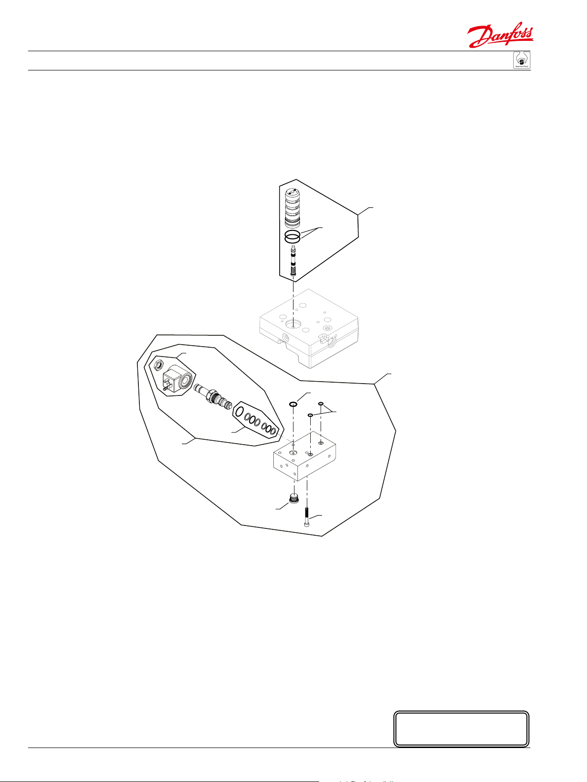
Parts Manual Series 51 160cc Variable Displacement Motor
Variable Displacement Motor
(K1 & K2)
F32
*F324
M1
QM200
QM100
M19
M1Q1
*M211
*M16E
M15
78
* = included in base motor seal kit Q210
520L0768 • Rev CA • September 2014
E103 125E
Enlarged bold type item
numbers are recommended
part to stock for servicing.
Page 79

Parts Manual Series 51 160cc Variable Displacement Motor
Variable Displacement Motor
Hydraulic proportional with electric override
Order Date Date Qty. per
code Item begin end Part number Part name model/kit
K1 F32 91-35 727115 4-way valve assembly 1
F324 91-35 730036 O-ring 2
M1 91-35 784942 Solenoid valve, 12 volt, DIN connector 1
M1Q1 91-35 503620 Control kit, 12 volt, DIN connector 1
M15 91-35 329599 Screw 4
M16E 91-35 732479 (9004105-0100) O-ring 2
M19 91-35 140644 Plug assembly 1
M211 91-35 365015 O-ring 1
K2 F32 91-35 727115 4-way valve assembly 1
F324 91-35 730036 O-ring 2
M1 91-35 784934 Solenoid valve, 24 volt, DIN connector 1
M1Q1 91-35 503806 Control kit, 24 volt, DIN connector 1
M15 91-35 329599 Screw 4
M16 91-35 732479 (9004105-0100) O-ring 2
M19 91-35 140644 Plug assembly 1
M211 91-35 365015 O-ring 1
520L0768 • Rev CA • September 2014
79
Page 80

Parts Manual Series 51 160cc Variable Displacement Motor
Variable Displacement Motor
(L1, L2, L7 & L8) (L3 & L4)
Used prior to 03-08
G36
G42
G38
M1
M18
M200
G38
G42
*F324
QM200
*G420
M18M18
M11
M22
F32
G38
M1Q1
Used prior to 06-01
M11
M16
Used prior to 03-08
G36
G42
M1200
M16
M1
M18
M200
G38
G42
*F324
QM200
F32
*G420
Used prior to 06-01
M18M18
M11
M22
M1Q1
M11
M1200
M16
M16
80
* = included in base motor seal kit Q210
E103 167E
Enlarged bold type item
numbers are recommended
part to stock for servicing.
520L0768 • Rev CA • September 2014
Page 81

Parts Manual Series 51 160cc Variable Displacement Motor
Variable Displacement Motor
Electric proportional common parts
Order Date Date Qty. per
code Item begin end Part number Part name model/kit
F32 95-35 509845 4-way valve assembly 1
F324 95-35 730036 O-ring 2
G36 95-35 03-07 364976 O-ring (SB-2002-001) 1
G38 95-35 03-07 792739 O-ring (SB-2002-001) 3
G42 95-35 03-07 754580 O-ring (SB-2002-001) 3
G420 03-08 511851 Gasket/O-ring seal (SB-2002-001) 1
M11 06-01 11000893 Shuttle valve 1
M11 92-33 05-52 759415 Shuttle valve 1
M16 92-33 140644 Plug assembly 1
M18 92-33 11040532 Plug assembly 2
M22 92-33 085183 Screw 4
M1200 92-33 05-52 759423 Orice plug 1
Electric proportional
L1 M1 95-35 11026442 Solenoid valve, 12 volt, DIN connector 1
M1Q1 95-35 518248 Control kit, 12 volt, DIN connector 1
M200 95-35 11026452 Coil kit, 12 volt, DIN connector
QM200 95-35 11121251 Coil nut kit 1
L2 M1 95-35 11026443 Solenoid valve, 24 volt, DIN connector 1
M1Q1 95-35 518245 Control kit, 24 volt, DIN connector 1
M200 95-35 11026453 Coil kit, 24 volt, DIN connector
QM200 95-35 11121251 Coil nut kit 1
L3 M1 01-19 11026447 Solenoid, 12 volt, Deutsch connector 1
M1Q1 01-19 519529/P Control kit, 12 volt, Deutsch connector 1
M200 01-19 11026454 Coil kit, 12 volt, Deutsch connector 1
QM200 01-19 11121272 Coil nut kit 1
L4 M1 96-24 11048359 Solenoid, 24 volt 1
M1Q1 96-24 11048357 Control kit, 24 volt 1
M200 96-24 11048358 Coil kit, 24 volt 1
QM200 96-24 11121272 Coil nut kit 1
L7 M1 96-38 11026438 Solenoid, 12 volt 1
M1Q1 96-38 518244 Control kit, 12 volt 1
M200 96-38 11026450 Coil kit, 12 volt 1
QM200 96-38 11121251 Coil nut kit 1
L8 M1 10-50 11026440 Solenoid, 24 volt 1
M1Q1 10-50 11092297 Control kit, 24 volt 1
M200 10-50 11026451 Coil kit, 24 volt 1
QM200 10-50 11121251 Coil nut kit 1
520L0768 • Rev CA • September 2014
81
Page 82

Parts Manual Series 51 160cc Variable Displacement Motor
Variable Displacement Motor
(N2)
M98
*M16N
Used prior to 03-08
G36
G42
G38
G38
G42
M1Q1
*M12N
M405
*G420
M150
82
* = included in base motor seal kit Q210
520L0768 • Rev CA • September 2014
E103 168E
Enlarged bold type item
numbers are recommended
part to stock for servicing.
Page 83

Parts Manual Series 51 160cc Variable Displacement Motor
Variable Displacement Motor
Hydraulic 2-position
Order Date Date Qty. per
code Item begin end Part number Part name model/kit
N2 G36 92-33 03-07 364976 O-ring (SB-2002-001) 1
G38 92-33 03-07 792739 O-ring (SB-2002-001) 3
G42 92-33 03-07 754580 O-ring (SB-2002-001) 3
G420 03-08 511851 Gasket/O-ring seal (SB-2002-001) 1
M1Q1 92-33 518227 Control kit 1
M12N 92-33 730036 O-ring 1
M16N 92-33 084673 Sealing ring 2
M98 92-33 745331 Plug assembly 1
M150 92-33 085183 Screw 4
M405 92-33 510415 Sleeve assembly 1
520L0768 • Rev CA • September 2014
83
Page 84

Parts Manual Series 51 160cc Variable Displacement Motor
Variable Displacement Motor
Used prior to 03-08
G36
G42
G38
M98
*M96
G38
G42
(PC)
F32
*F324
84
M16
M27
*G420
M321
M360
M27
M58
M23
M27
M16
*M24P
M27
M27
* = included in base motor seal kit Q210
520L0768 • Rev CA • September 2014
M27
M27
M360
*M82
M1Q1
M14
*M16J
QZ10
M26
M20
M29
M27
E100 308E
Enlarged bold type item
numbers are recommended
part to stock for servicing.
Page 85

Parts Manual Series 51 160cc Variable Displacement Motor
Variable Displacement Motor
Pressure compensator
Order Date Date Qty. per
code Item begin end Part number Part name model/kit
PC F32 92-33 13-24 510416 4-way valve assembly 1
F324 92-33 13-24 730036 O-ring 2
G36 92-33 03-07 364976 O-ring (SB-2002-001) 1
G38 92-33 03-07 792739 O-ring (SB-2002-001) 3
G42 92-33 03-07 754580 O-ring (SB-2002-001) 3
G420 03-08 13-24 511851 Gasket/O-ring seal (SB-2002-001) 1
M1Q1 92-33 13-24 518224 Control kit, PC 1
M14 92-33 13-24 342709 (9003575-0101) Nut 1
M16 92-33 13-24 140644 Plug assembly 2
M16J 92-33 13-24 001149 (9004201-6200) O-ring 1
M20 92-33 13-24 746016 Piston valve 1
M23 92-33 13-24 315325 (9005110-8700) Plug assembly 1
M24P 92-33 13-24 732479 (9004105-0100) O-ring 4
M26 92-33 13-24 509152 Spring 1
M27 92-33 13-24 11040532 Plug assembly 16
M29 92-33 13-24 713719 (9007314-0610) Screw 4
M58 92-33 13-24 503499 Screw 4
M82 92-33 13-24 144725 (9004105-0110) O-ring 1
M96 92-33 13-24 084673 Sealing ring 1
M98 92-33 13-24 745331 Plug 1
M321 92-33 13-24 519114 Shuttle valve assembly 1
M360 92-33 13-24 092114 (9007712-0604) Set screw 4
520L0768 • Rev CA • September 2014
85
Page 86

Parts Manual Series 51 160cc Variable Displacement Motor
Variable Displacement Motor
(PD)
Used prior to 03-08
G38
G42
G36
G38
G42
*F324
F32
86
M16
M27
*G420
M321
M360
M27
M58
M23
M27
M16
*M24P
M27
M27
* = included in base motor seal kit Q210
520L0768 • Rev CA • September 2014
M27
*M82
M1Q1
M14
*M16J
QZ10
M26
M20
M29
M27
E103 169E
Enlarged bold type item
numbers are recommended
part to stock for servicing.
Page 87

Parts Manual Series 51 160cc Variable Displacement Motor
Variable Displacement Motor
Pressure compensator
Order Date Date Qty. per
code Item begin end Part number Part name model/kit
PD F32 92-40 13-24 500820 4-way valve assembly 1
F324 92-40 13-24 730036 O-ring 2
G36 92-40 03-07 364976 O-ring (SB-2002-001) 1
G38 92-40 03-07 792739 O-ring (SB-2002-001) 3
G42 92-40 03-07 754580 O-ring (SB-2002-001) 3
G420 03-08 13-24 511851 Gasket/O-ring seal (SB-2002-001) 1
M1Q1 92-40 13-24 518232 Control kit, PD 1
M14 92-40 13-24 342709 (9003575-0101) Nut 1
M16 92-40 13-24 140644 Plug assembly 2
M16J 92-40 13-24 001149 (9004201-6200) O-ring 1
M20 92-40 13-24 501876 Spool assembly 1
M23 92-40 13-24 315325 (9005110-8700) Plug assembly 1
M24P 92-40 13-24 732479 (9004105-0100) O-ring 4
M26 92-40 13-24 509152 Spring 1
M27 92-40 13-24 11040532 Plug assembly 13
M29 92-40 13-24 713719 (9007314-0610) Screw 4
M58 92-40 13-24 714436 Screw 4
M82 92-40 13-24 144725 (9004105-0110) O-ring 1
M321 92-40 13-24 519114 Shuttle valve assembly 1
M360 92-40 13-24 092114 (9007712-0604) Set screw 4
520L0768 • Rev CA • September 2014
87
Page 88

Parts Manual Series 51 160cc Variable Displacement Motor
Variable Displacement Motor
(T1 & T2)
Used prior to 03-08
G38
G42
G36
*G420
G38
G42
M12
*F324
F32
M1
M18
M200
M16
QM200
M22
88
* = included in base motor seal kit Q210
520L0768 • Rev CA • September 2014
E100 333E
Enlarged bold type item
numbers are recommended
part to stock for servicing.
Page 89

Parts Manual Series 51 160cc Variable Displacement Motor
Variable Displacement Motor
Electric 2-position
Order Date Date Qty. per
code Item begin end Part number Part name model/kit
T1 F32 96-31 503380 4-way valve assembly 1
F324 96-31 730036 O-ring 2
G36 96-31 03-07 364976 O-ring (SB-2002-001) 1
G38 96-31 03-07 792739 O-ring (SB-2002-001) 3
G42 96-31 03-07 754580 O-ring (SB-2002-001) 3
G420 03-08 511851 Gasket/O-ring seal (SB-2002-001) 1
M1 96-31 11026435 Solenoid valve, 12 volt, DIN connector 1
M12 96-31 11082448 Sensing piston 1
M16 96-31 140644 Plug assembly 1
M18 96-31 11040532 Plug assembly 1
M22 96-31 503499 Screw 4
M200 96-31 11026448 Coil kit, 12 volt, Din connector 1
QM200 96-31 11121273 Coil nut kit 1
T2 F32 96-31 503380 4-way valve assembly 1
F324 96-31 730036 O-ring 2
G36 96-31 03-07 364976 O-ring (SB-2002-001) 1
G38 96-31 03-07 792739 O-ring (SB-2002-001) 3
G42 96-31 03-07 754580 O-ring (SB-2002-001) 3
G420 03-08 511851 Gasket/O-ring seal (SB-2002-001) 1
M1 96-31 11026436 Solenoid valve, 24 volt, DIN connector 1
M12 96-31 11082448 Sensing piston 1
M16 96-31 140644 Plug assembly 1
M18 96-31 11040532 Plug assembly 1
M22 96-31 503499 Screw 4
M200 96-31 11026449 Coil kit, 24 volt, Din connector 1
QM200 96-31 11121273 Coil nut kit 1
520L0768 • Rev CA • September 2014
89
Page 90

Parts Manual Series 51 160cc Variable Displacement Motor
Variable Displacement Motor
(T3 & T4)
Used prior to 03-08
G38
G42
G36
*G420
G38
G42
M12
*F324
F32
M1
M18
M200
M16
QM200
M22
90
* = included in base motor seal kit Q210
520L0768 • Rev CA • September 2014
E103 170E
Enlarged bold type item
numbers are recommended
part to stock for servicing.
Page 91

Parts Manual Series 51 160cc Variable Displacement Motor
Variable Displacement Motor
Electric 2-position
Order Date Date Qty. per
code Item begin end Part number Part name model/kit
T3 F32 96-31 503380 4-way valve assembly 1
F324 96-31 730036 O-ring 2
G36 96-31 03-07 364976 O-ring (SB-2002-001) 1
G38 96-31 03-07 792739 O-ring (SB-2002-001) 3
G42 96-31 03-07 754580 O-ring (SB-2002-001) 3
G420 03-08 511851 Gasket/O-ring seal (SB-2002-001) 1
M1 96-31 519468 Solenoid valve, 12 volt 1
M12 96-31 11082448 Piston 1
M16 96-31 140644 Plug assembly 1
M18 96-31 11040532 Plug assembly 1
M22 96-31 503499 Screw 4
M200 96-31 519467 Coil kit, 12 volt 1
QM200 96-31 11121272 Coil nut kit 1
T4 F32 00-39 503380 4-way valve assembly 1
F324 00-39 730036 O-ring 2
G36 00-39 03-07 364976 O-ring (SB-2002-001) 1
G38 00-39 03-07 792739 O-ring (SB-2002-001) 3
G42 00-39 03-07 754580 O-ring (SB-2002-001) 3
G420 03-08 511851 Gasket/O-ring seal (SB-2002-001) 1
M1 00-39 11003624 Solenoid valve, 24 volt 1
M12 00-39 11082448 Piston 1
M16 00-39 140644 Plug assembly 1
M18 00-39 11040532 Plug assembly 1
M22 00-39 503499 Screw 4
M200 00-39 11003626 Coil kit, 24 volt 1
QM200 00-39 11121272 Coil nut kit 1
520L0768 • Rev CA • September 2014
91
Page 92

Parts Manual Series 51 160cc Variable Displacement Motor
Variable Displacement Motor
(TA) (TH)
Used prior to 03-08
G36
G42
G38
M18
G38
G42
M12
M1TA
*F324
M16
*G420
F32
M22
Used prior to 03-08
G36
G42
G38
(TM & TN)
M18
G38
G42
M12
F32
*F324
M16
F32
*G420
M22
* = included in base motor seal kit Q210
*F324
M12
M18
M18
M18
M1
M200
QM200
E103 171E
Enlarged bold type item
numbers are recommended
part to stock for servicing.
92
520L0768 • Rev CA • September 2014
Page 93

Parts Manual Series 51 160cc Variable Displacement Motor
Variable Displacement Motor
Pressure compensator
Order Date Date Qty. per
code Item begin end Part number Part name model/kit
TA F32 97-02 503380 4-way valve assembly 1
F324 97-02 730036 O-ring 2
G36 97-02 03-07 364976 O-ring (SB-2002-001) 1
G38 97-02 03-07 792739 O-ring (SB-2002-001) 3
G42 97-02 03-07 754580 O-ring (SB-2002-001) 3
G420 03-08 511851 Gasket/O-ring seal (SB-2002-001) 1
M1TA 97-02 140644 Plug assembly 1
M12 97-02 11082448 Sensing piston 1
M16 97-02 140644 Plug assembly 1
M18 97-02 11040532 Plug assembly 1
M22 97-02 503499 Screw 4
Hydraulic 2-position
TH F32 97-02 503380 4-way valve assembly 1
F324 97-02 730036 O-ring 2
G36 97-02 03-07 364976 O-ring (SB-2002-001) 1
G38 97-02 03-07 792739 O-ring (SB-2002-001) 3
G42 97-02 03-07 754580 O-ring (SB-2002-001) 3
G420 03-08 511851 Gasket/O-ring seal (SB-2002-001) 1
M12 97-02 11083129 Sensing piston 1
M16 97-02 140644 Plug assembly 1
M18 97-02 11040532 Plug assembly 1
M22 97-02 503499 Screw 4
Electric 2-position
TM F32 99-30 11001792 4-way valve assembly 1
F324 99-30 730036 O-ring 2
M1 99-30 11026438 Solenoid valve, 12 volt, Jet connector 1
M12 99-30 11082448 Piston 1
M18 99-30 11040532 Plug assembly 3
M200 99-30 11026450 Coil kit, 12 volt, Jet connector 1
QM200 99-30 11121251 Coil nut kit 1
TN F32 99-30 11001792 4-way valve assembly 1
F324 99-30 730036 O-ring 2
M1 99-30 11026440 Solenoid valve, 24 volt, Jet connector 1
M12 99-30 11082448 Piston 1
M18 99-30 11040532 Plug assembly 3
M200 99-30 11026451 Coil kit, 24 volt, Jet connector 1
QM200 99-30 11121251 Coil nut kit 1
520L0768 • Rev CA • September 2014
93
Page 94

Parts Manual Series 51 160cc Variable Displacement Motor
Variable Displacement Motor
(TP) (TW, U3 & U4)
M1
*G420
M18
M18
M12
*F324
M18
F32
M22
M1
*G420
M18
M12
*F324
M16
F32
M22
94
M200
QM200
* = included in base motor seal kit Q210
520L0768 • Rev CA • September 2014
M200
QM200
E103 172E
Enlarged bold type item
numbers are recommended
part to stock for servicing.
Page 95

Parts Manual Series 51 160cc Variable Displacement Motor
Variable Displacement Motor
Electric 2-position
Order Date Date Qty. per
code Item begin end Part number Part name model/kit
TP F32 04-07 503925 4-way valve assembly 1
F324 04-07 730036 O-ring 2
G420 04-07 511851 Gasket/O-ring seal 1
M1 04-07 519468 Solenoid valve, 12 volt, Jet connector 1
M12 04-07 11082448 Piston 1
M18 04-07 11040532 Plug assembly 3
M22 04-07 503499 Screw 4
M200 04-07 519467 Coil kit, 12 volt, Jet connector 1
QM200 04-07 11121272 Coil nut kit 1
TW F32 05-12 11001792 4-way valve assembly 1
F324 05-12 730036 O-ring 2
G420 05-12 511851 Gasket/O-ring seal 1
M1 05-12 519468 Solenoid valve, 12 volt, Jet connector 1
M12 05-12 11082448 Piston 1
M16 05-12 140644 Plug assembly 1
M18 05-12 11040532 Plug assembly 1
M22 05-12 503499 Screw 4
M200 05-12 519467 Coil kit, 12 volt, Jet connector 1
QM200 05-12 11121272 Coil nut kit 1
U3 F32 11-08 503925 4-way valve assembly 1
F324 11-08 730036 O-ring 2
G420 11-08 511851 Gasket/O-ring seal 1
M1 11-08 519468 Solenoid valve, 12 volt, Jet connector 1
M12 11-08 507292 Piston 1
M16 11-08 140644 Plug assembly 1
M18 11-08 11040532 Plug assembly 1
M22 11-08 503499 Screw 4
M200 11-08 519467 Coil kit, 12 volt, Jet connector 1
QM200 11-08 11121272 Coil nut kit 1
U4 F32 11-08 503925 4-way valve assembly 1
F324 11-08 730036 O-ring 2
G420 11-08 511851 Gasket/O-ring seal 1
M1 11-08 11003624 Solenoid valve, 24 volt, Jet connector 1
M12 11-08 507292 Piston 1
M16 11-08 140644 Plug assembly 1
M18 11-08 11040532 Plug assembly 1
M22 11-08 503499 Screw 4
M200 11-08 11003626 Coil kit, 24 volt, Jet connector 1
QM200 11-08 11121272 Coil nut kit 1
520L0768 • Rev CA • September 2014
95
Page 96

Parts Manual Series 51 160cc Variable Displacement Motor
Variable Displacement Motor
M15
M1
QM034
M18
M16
M18
M150
*F324
*G420
M16
M18
M18
F32
M18
M321
(Y3 & Y8)
M1Q1
M18
M18
M18
M16
M16
M151
M15
QM034
M1
* = included in base motor seal kit Q210
96
520L0768 • Rev CA • September 2014
M150
*F324
*G420
M16
M18
M18
M18
M18
F32
M18
M18
M151
(YA & YB)
M1Q1
M18
M16
E103 173E
Enlarged bold type item
numbers are recommended
part to stock for servicing.
Page 97

Parts Manual Series 51 160cc Variable Displacement Motor
Variable Displacement Motor
Electric proportional
Order Date Date Qty. per
code Item begin end Part number Part name model/kit
Y3 F32 03-15 727115 4-way valve assembly 1
F324 03-15 730036 O-ring 2
G420 03-15 511851 Gasket/O-ring seal 1
M1 03-15 519448 Solenoid valve, 12 volt, Deutsch connector 1
M1Q1 03-15 519576 Control kit 1
M15 03-15 067694 Screw 2
M16 03-15 140644 Plug assembly 4
M18 03-15 11040532 Plug assembly 10
M150 03-15 503499 Screw 2
M151 03-15 348060 Screw 2
M321 03-15 519114 Spool 1
QM034 03-15 11099849 Solenoid valve seal kit 1
Y8 F32 03-15 727115 4-way valve assembly 1
F324 03-15 730036 O-ring 2
G420 03-15 511851 Gasket/O-ring seal 1
M1 03-15 518081 Solenoid valve, 24 volt, Jet connector 1
M1Q1 03-15 11052890 Control kit 1
M15 03-15 067694 Screw 2
M16 03-15 140644 Plug assembly 4
M18 03-15 11040532 Plug assembly 10
M150 03-15 503499 Screw 2
M151 03-15 348060 Screw 2
M321 03-15 519114 Spool 1
QM034 03-15 11099849 Solenoid valve seal kit 1
YA F32 04-27 727115 4-way valve assembly 1
F324 04-27 730036 O-ring 2
G420 04-27 511851 Gasket/O-ring seal 1
M1 04-27 519448 Solenoid valve, 12 volt, Deutsch connector 1
M1Q1 04-27 521262 Control kit 1
M15 04-27 067694 Screw 2
M16 04-27 140644 Plug assembly 2
M18 04-27 11040532 Plug assembly 7
M150 04-27 503499 Screw 2
M151 04-27 348060 Screw 2
QM034 04-27 11099849 Solenoid valve seal kit 1
YB F32 04-27 727115 4-way valve assembly 1
F324 04-27 730036 O-ring 2
G420 04-27 511851 Gasket/O-ring seal 1
M1 04-27 519448 Solenoid valve, 12 volt, Deutsch connector 1
M1Q1 04-27 521263 Control kit 1
M15 04-27 067694 Screw 2
M16 04-27 140644 Plug assembly 2
M18 04-27 11040532 Plug assembly 7
M150 04-27 503499 Screw 2
M151 04-27 348060 Screw 2
QM034 04-27 11099849 Solenoid valve seal kit 1
520L0768 • Rev CA • September 2014
97
Page 98

Parts Manual Series 51 160cc Variable Displacement Motor
Variable Displacement Motor
G38
Used prior to 03-08
N32
N26
N30
N27
G42
N36
G36
N27
M58
G38
G42
N23
*G420
N27
N27
N27
N27
(A1 & A3)
*QN84
N27
N27
N36
N26
*N24
N84
*QN84
*N82
N26
N84
N87
N14
*N16
QZ10
N18
N20
N29
G42
G38
Used prior to 03-08
N26
N27
G36
N30
N27
M58
G38
N36
G42
N23
*G420
N27
N27
N27
(A2 & A4)
N27
N27
N36
N26
*N24
*N82
N27
N14
*N16
QZ10
N18
N20
N87
N29
98
* = included in base motor seal kit Q210
520L0768 • Rev CA • September 2014
N27
E100 309E
Enlarged bold type item
numbers are recommended
part to stock for servicing.
Page 99

Parts Manual Series 51 160cc Variable Displacement Motor
Variable Displacement Motor
Servo pressure supply
Order Date Date Qty. per
code Item begin end Part number Part name model/kit
A1 & A3 G36 92-33 03-07 364976 O-ring (SB-2002-001) 1
G38 92-33 03-07 792739 O-ring (SB-2002-001) 3
G42 92-33 03-07 754580 O-ring (SB-2002-001) 3
G420 03-08 511851 Gasket/O-ring seal (SB-2002-001) 1
N14 92-33 342709 (9003575-0101) Nut 1
N16 92-33 001149 (9004201-6200) O-ring 1
N18 92-33 509152 Spring 1
N20 92-33 746016 Relief valve 1
N23 92-33 315325 (9005110-8700) Plug assembly 1
N24 92-33 732479 (9004105-0100) O-ring 4
N26 92-33 140644 Plug assembly 3
N27 92-33 11040532 Plug assembly 18
N29 92-33 713719 (9007314-0610) Screw 4
N30 92-33 519114 Shuttle valve assembly 1
N32 92-33 346080 Spool 1
N36 92-33 092114 (9007712-0604) Set screw 4
N58 92-33 714436 Screw 4
N82 92-33 144725 (9004105-0110) O-ring 1
N84 92-33 735266 Stop assembly 2
QN84 92-33 039297 (9004201-1200) O-ring 2
N87 92-33 503887 PCOR housing assembly 1
A2 & A4 G36 92-33 03-07 364976 O-ring (SB-2002-001) 1
G38 92-33 03-07 792739 O-ring (SB-2002-001) 3
G42 92-33 03-07 754580 O-ring (SB-2002-001) 3
G420 03-08 511851 Gasket/O-ring seal (SB-2002-001) 1
N14 92-33 342709 (9003575-0101) Nut 1
N16 92-33 001149 (9004201-6200) O-ring 1
N18 92-33 509152 Spring 1
N20 92-33 746016 Relief valve 1
N23 92-33 315325 (9005110-8700) Plug assembly 1
N24 92-33 732479 (9004105-0100) O-ring 4
N26 92-33 140644 Plug assembly 2
N27 92-33 11040532 Plug assembly 16
N29 92-33 713719 (9007314-0610) Screw 4
N30 92-33 519114 Shuttle valve assembly 1
N36 92-33 092114 (9007712-0604) Set screw 4
N58 92-33 714436 Screw 4
N82 92-33 144725 (9004105-0110) O-ring 1
N87 92-33 503887 PCOR housing assembly 1
520L0768 • Rev CA • September 2014
99
Page 100

Parts Manual Series 51 160cc Variable Displacement Motor
Variable Displacement Motor
(A5 & A6)
G42
G38
Used prior to 03-08
Used prior to 03-08
N26
G36
G38
G38
N30
G42
G42
N27
G36
N36
N27
*G420
G38
G42
*G420
N27
N27
N36
N26
M58
(A7)
100
N26
N27
N30
N36
N27
M58
X008
X12
N27
N26
*N24
N27
N27
*X11
* = included in base motor seal kit Q210
520L0768 • Rev CA • September 2014
N27
N27
N36
*N82
N87
N27
N14
*N16
QZ10
N18
N20
N29
E100 312E
Enlarged bold type item
numbers are recommended
part to stock for servicing.
 Loading...