

Page 1

User Guide
VACON® OPTEA/OPTE9 Ethernet Board
Page 2

Page 3

VACON® OPTEA/OPTE9 Ethernet Board
User Guide
Contents
1
Introduction 10
1.1
Purpose of the Manual 10
Additional Resources 10
1.2
Manual and Software Version 10
1.3
1.4
Type Approvals and Certications 11
1.5
Trademarks 11
1.6
Product Overview 12
1.6.1
Ethernet Networks with VACON® AC drives 12
1.6.2
Fieldbus Protocols 12
1.6.2.1
1.6.2.2
1.6.2.3
Redundancy Protocols 17
1.6.3
Modbus TCP/Modbus UDP 12
PROFINET I/O 16
EtherNet/IP 17
Contents
1.6.3.1
1.6.3.2
1.6.3.3
1.6.3.4
1.6.4
PROFINET Shared Device (OPTEA) 23
1.6.5
Address Conict Detection (ACD) 24
1.6.6
Technical Data 24
1.6.7
VACON® PC Tools 24
1.7
AC Drive Support 25
1.7.1
VACON® OPTEA Advanced Dual Port Ethernet Drive Support 25
1.7.2
VACON® OPTE9 Dual Port Ethernet Drive Support 25
1.8
Symbols and Abbreviations 26
2
Safety 29
2.1
Safety Symbols 29
2.2
Danger and Warnings 29
2.3
Cautions and Notices 30
Rapid Spanning Tree Protocol (RSTP) 17
Media Redundancy Protocol (MRP) 19
Device Level Ring (DLR) 20
PROFINET System Redundancy (OPTEA) 22
2.4
Grounding 32
3
Commissioning 34
3.1
Before Commissioning 34
3.1.1
Installing VACON® PC Tools 34
3.1.2
Downloading Fieldbus Option Firmware 34
3.1.3
Downloading Function Blocks for PLC 34
BC346130105092EN-US-000101/DPD01583 | 3Danfoss A/S © 2020.06
Page 4

VACON® OPTEA/OPTE9 Ethernet Board
User Guide
3.2
Commissioning with VACON® PC tools 35
3.2.1
Updating Fieldbus Firmware with VACON® Loader 35
3.2.2
Updating Firmware over Ethernet with VACON® Loader 36
3.2.3
Conguring with VACON® NCIPCong 39
3.2.4
Setting the Drive Parameters 40
3.2.4.1
3.2.4.2
3.3
OPTCx Emulation Mode (OPTEA) 43
4
Control Interface and Communication 46
4.1
Ethernet Communication Overview 46
4.2
Fieldbus Option Board Communication Modes 46
4.2.1
Requirements for Communication Modes 46
4.2.2
Fieldbus Communication Mode Features and Limitations 47
4.2.3
Normal Fieldbus Communication 47
Setting the Drive Parameters with VACON® NCDrive 40
Setting the Drive Parameters with VACON® Live 42
Contents
4.2.4
Fast Fieldbus Communication 48
4.2.5
Fast Safety Fieldbus Communication 49
4.2.6
Normal Extended Mode 49
4.3
Drive Control with Modbus TCP/UDP 49
4.3.1
Modbus Communication Overview 49
4.3.2
Quick Setup for Modbus Connection 49
4.3.3
Data Addresses and Modbus Memory Map 49
4.3.4
Coil Registers 50
4.3.5
Resettable Trip Counters 50
4.3.6
Input Discrete Registers 51
4.3.7
Input Registers 51
4.3.8
Holding Registers 51
4.3.8.1
4.3.8.2
4.3.8.3
4.3.8.4
VACON® Application IDs 52
FB Process Data In 52
FB Process Data Out 54
ID Map 55
4.3.8.5
4.3.8.6
4.3.8.7
4.3.8.8
4.3.8.9
4.3.8.10
4.3.8.11
Operation Day Counter 56
Resettable Operation Day Counter 57
Energy Counter 57
Resettable Energy Counter 58
Fault History 59
Fault History with 16-bit Error Codes 59
Reset Fault History 59
BC346130105092EN-US-000101/DPD015834 | Danfoss A/S © 2020.06
Page 5

VACON® OPTEA/OPTE9 Ethernet Board
User Guide
4.4
Contents
4.3.8.12
4.3.9
Connection Timeout in Modbus Communication 60
4.3.10
Example Messages 61
4.3.10.1
4.3.10.2
4.3.10.3
Drive Control with PROFINET 63
4.4.1
PROFINET Communication Overview 63
4.4.2
Quick Setup for PROFINET Connection 64
4.4.3
PROFIdrive 4.1 Prole Overview 64
4.4.4
PROFIdrive 4.1 State Machine 64
4.4.5
Telegram Types 66
4.4.5.1
4.4.5.2
Reset Fault with Time Stamps 59
Write Process Data 61
Read Process Data 62
Exception Response 63
Standard Telegram 1 and Variants 67
VACON®-specic Telegram 1 and Variants 68
4.4.5.3
4.4.5.4
4.4.5.5
4.4.5.6
4.4.5.7
4.4.6
Telegram Building Blocks 74
4.4.6.1
4.4.6.2
4.4.6.3
4.4.6.4
4.4.7
PROFIdrive Signal Numbers 77
4.4.8
User-specic Record Data 80
4.4.9
Connection Timeout in PROFINET 80
4.4.10
Examples with Siemens Controller 81
4.4.10.1
4.4.10.2
VACON®-specic Telegram 2 and Variants 69
VACON®-specic Telegram 3 and Variants 70
VACON®-specic Telegram 4 and Variants 71
VACON®-specic Telegram 5 and Variants 72
VACON®-specic Telegram Vendor PPO and Variants 72
PROFIdrive 4.1 Control Word (STW1) 74
PROFIdrive 4.1 Status Word (ZSW1) 75
Setpoint Value 76
Actual Speed Value 77
Conguring with Step 7 81
Conguring with TIA Portal 90
4.4.10.3
4.5
PROFIsafe (OPTEA) 102
4.5.1
Introduction to PROFIsafe 102
4.5.2
PROFIdrive on PROFIsafe 103
4.6
Drive Control with EtherNet/IP 103
4.6.1
EtherNet/IP Communication Overview 103
4.6.2
Quick Setup for EtherNet/IP Connection 104
4.6.3
AC/DC Drive Prole 105
Conguring with SIMATIC PDM 97
BC346130105092EN-US-000101/DPD01583 | 5Danfoss A/S © 2020.06
Page 6

VACON® OPTEA/OPTE9 Ethernet Board
User Guide
4.6.4
EDS File 105
4.6.5
CIP Objects 105
4.6.5.1
4.6.5.2
4.6.5.3
4.6.5.4
4.6.5.5
4.6.5.6
4.6.5.7
4.6.5.8
4.6.5.9
4.6.6
Vendor-specic Objects 126
4.6.6.1
4.6.6.2
Identity Object, Class 0x01 105
Message Router Object, Class 0x02 108
Connection Manager Object, Class 0x06 109
TCP/IP Interface Object, Class 0xF5 110
Ethernet Link Object, Class 0xF6 115
Assembly Object, Class 0x04 118
Motor Data Object, Class 0x28 119
Control Supervisor Object, Class 0x29 120
AC/DC Drive Object, Class 0x2A 123
Vendor Parameters Object, Class 0xA0 126
Assembly Instance Selector Object, Class 0xBE 127
Contents
4.6.6.3
4.6.6.4
4.6.7
Supported Assembly Instances Overview 132
4.6.8
CIP I/O Assembly Instances for AC/DC Drive 133
4.6.8.1
4.6.8.2
4.6.9
Vendor-specic I/O Assembly Instances 137
4.6.9.1
4.6.9.2
4.6.10
Mapping of Standard Output Assemblies onto VACON® Data 149
4.6.11
Mapping of VACON® Data onto Standard Input Assemblies 150
4.6.12
Special Assembly Instances 150
4.6.13
Connection Timeout in EtherNet/IP Communication 150
4.7
VACON® Process Data Description 151
4.7.1
Control Word Overview 151
4.7.2
Status Word Overview 155
Motor Control Mode Object, Class 0xA1 129
Fault History Object, class 0xA2 131
CIP Output Instances 135
CIP Input Instances 136
Vendor Output Instances 137
Vendor Input Instances 143
4.7.3
Control and Status Word Monitoring Values 158
4.7.4
Speed Reference and Actual Speed 159
4.7.5
Process Data 159
4.7.6
Fieldbus Process Data 159
4.8
Time Synchronization 162
4.8.1
System Time Update with ID 2551 162
4.8.2
Simple Network Time Protocol (SNTP) 162
BC346130105092EN-US-000101/DPD015836 | Danfoss A/S © 2020.06
Page 7

VACON® OPTEA/OPTE9 Ethernet Board
User Guide
5
Parameter Access 163
Parameter Access with PROFINET 163
5.1
5.1.1
Parameter Access Sequence 163
Parameter Requests 163
5.1.2
5.1.2.1
5.1.2.2
5.1.2.3
5.1.3
Parameter Responses 165
5.1.3.1
5.1.3.2
5.1.3.3
5.1.3.4
5.1.3.5
5.1.3.6
Request Header 164
Parameter Address 164
Parameter Value 165
Error Response 166
PROFIdrive 4.1 Error Classes and Codes 166
PROFIdrive Parameter Access Errors 167
Response Header 169
Parameter Values 169
Parameter Description Elements 169
Contents
Drive Parameter Access Using Application ID 170
5.1.4
5.1.5
PROFINET Parameters 170
5.1.5.1
5.1.5.2
5.1.5.3
5.1.6
Parameter Channel Examples 173
5.1.6.1
5.1.6.2
5.1.6.3
5.1.6.4
5.1.6.5
5.1.6.6
5.2
Parameter Access with EtherNet/IP 179
5.2.1
Explicit Messaging 179
5.2.2
List of Data Types 179
5.2.3
General CIP Error Codes 180
PROFIdrive Parameters 170
Vendor-specic PROFIdrive Parameters 171
Safety Parameters 173
Request First Element of PNU964 Value 174
Request All Elements of Parameter PNU964 175
Request the Value of Parameter ID 103 176
Change the Value of Drive Parameter ID 103 (Successful) 176
Change the Value of Drive Parameter ID 103 (Unsuccessful) 177
Change the Values of Multiple Drive Parameters (ID 103 and ID 104) 178
5.2.4
Connection Manager Object Error Codes 181
5.2.5
Supported CIP and Vendor Objects 182
6
Parameters 184
6.1
Option Board Parameters 184
6.1.1
Comm. Protocol 186
6.1.2
Comm. Timeout 186
6.1.3
Mode/Emulation 187
BC346130105092EN-US-000101/DPD01583 | 7Danfoss A/S © 2020.06
Page 8

VACON® OPTEA/OPTE9 Ethernet Board
User Guide
6.2
Contents
6.1.4
IP Address Mode 187
6.1.5
Speed and Duplex 188
6.1.6
IP Port Filtering 188
6.1.7
EIP Output Instance 189
6.1.8
EIP Input Instance 189
6.1.9
EIP Product Code Oset 189
6.1.10
Modbus Unit Identier 189
6.1.11
PNIO Name of Station 190
6.1.12
SNTP Mode 190
6.1.13
SNTP IP Address 190
6.1.14
SNTP Port 190
6.1.15
Time Interval 190
6.1.16
Time Oset 190
AC Drive Parameters 191
6.2.1
AC Drive Parameters for Fieldbus Control and Reference Selection 191
6.2.2
Protocol-related ID Reading and Writing 191
6.2.3
Fieldbus Parameters for VACON® 100 Family Standard Application 191
6.2.4
Fieldbus Parameters for VACON® 20 Standard Application 192
6.2.5
Fieldbus Parameters for VACON® 20 X Multipurpose Application 192
6.2.6
Fieldbus Parameters for VACON® NXP Multipurpose Application 192
6.2.7
Torque Control Parameterization 193
6.3
VACON® NXP System Software Parameters for Application Developers 193
6.3.1
System Software Variables for Selecting Communication Modes 194
6.3.2
System Software Variables for Monitoring Supported Communication Modes 194
6.3.3
System Software Variables for Selecting the Input Process Data Slot 194
7
Monitoring Values 195
7.1
Option Board Monitoring Values 195
7.1.1
MAC Address 197
7.1.2
Media Redundancy 197
7.1.3
System Redundancy (OPTEA) 198
7.1.4
SNTP Status 198
7.1.5
SNTP Server IP 198
7.1.6
Last Update Time 198
7.2
Monitoring Values of Control and Status Words 198
8
Fault Tracing 200
8.1
LED Indications on VACON® OPTEA/OPTE9 Option Boards 200
8.2
LED Indications with EtherNet/IP 201
BC346130105092EN-US-000101/DPD015838 | Danfoss A/S © 2020.06
Page 9

VACON® OPTEA/OPTE9 Ethernet Board
User Guide
8.3
8.4
8.5
8.6
8.7
8.8
Contents
PROFINET Alarm System 203
Fault Handling 205
Gathering Diagnostic Data 205
Typical Fault Conditions 205
Other Fault Conditions 206
Fieldbus Fault Codes 207
BC346130105092EN-US-000101/DPD01583 | 9Danfoss A/S © 2020.06
Page 10

•
•
•
•
•
•
•••••
•
NOTE! Download the English and French product manuals with applicable safety, warning and caution information from https://
www.danfoss.com/en/service-and-support/.
REMARQUE Vous pouvez télécharger les versions anglaise et française des manuels produit contenant l'ensemble des informations de sécurité, avertissements et mises en garde applicables sur le site https://www.danfoss.com/en/service-and-support/.
Manual version
New features
Firmware
version
DPD01583C (for
OPTE9)
EtherNet/IP protocol
Ethernet ring support (RSTP)
Address Conict Detection (ACD)
V004
(OPTE9)
DPD01583D (for
OPTE9)
Media Redundancy Protocol (MRP)
Simple Network Management Protocol (SNMP)
LLDP-MIB, LLDP-EXT-DOT3-MIB, LLDP-EXT-PNO-MIB
EDD les SIMATIC PDM
V006
(OPTE9)
DPD01583E (for
OPTE9)
Fast communication modes in VACON® NXP
PROFINET Alarms.
V007
(OPTE9)
DPD01583F (for
OPTE9)
Simple Network Time Protocol (SNTP).
Fast MRP support veried
V008
(OPTE9)
Device Level Ring (DLR)
V009
(OPTE9)
DPD01583G (for
OPTEA/OPTE9)
PROFINET + PROFIsafe for VACON® NXP
V001 (OPTEA)
VACON® OPTEA/OPTE9 Ethernet Board
User Guide
Introduction
1 Introduction
1.1 Purpose of the Manual
The EtherNet/IP user guide provides information about conguring the system, controlling the drive, accessing parameters, programming, troubleshooting, and some typical application examples.
The user guide is intended for use by qualied personnel, who are familiar with the VACON® drives, EtherNet/IP technology, and
with the PC or PLC that is used as a master in the system.
Read the instructions before commissioning and programming and follow the procedures in this manual.
1.2 Additional Resources
Resources available for the drive and optional equipment are:
•
VACON® Ethernet Installation Guide provides the necessary information to install the option board to the AC drive.
•
The Operating Guide of the AC drive provides the necessary information to get the drive up and running.
•
The Application Guide of the AC drive provides more details on working with parameters and many application examples.
Supplementary publications and manuals are available from drives.danfoss.com/knowledge-center/technical-documentation/.
For US and Canadian markets:
1.3 Manual and Software Version
This manual is regularly reviewed and updated. All suggestions for improvement are welcome.
The original language of this manual is English.
Table 1: Manual and Software Version
BC346130105092EN-US-000101 / DPD0158310 | Danfoss A/S © | 2020.06
Page 11
•
•
•
•
•
Manual version
New features
Firmware
version
Support for all features supported by OPTE9 board including EtherNet/IP and Modbus
TCP/UDP protocols
Improved emulation mode with OPTCP, OPTCQ, and OPTCI boards when installed to VACON® NXP
PROFINET System Redundancy "S2"
V002 (OPTEA)
DPD01583H (for
OPTEA/OPTE9)
The structure of the manual updated. Installation information removed (see VACON
®
Ethernet Installation Guide).
Support for 32-bit process data items with VACON® 100 family AC drives.
V003 (OPTEA)
Shared Device
V005 (OPTEA)
089
VACON® OPTEA/OPTE9 Ethernet Board
User Guide
1.4 Type Approvals and Certications
The following list is a selection of possible type approvals and certications for Danfoss drives:
Introduction
N O T I C E
The specic approvals and certication for the drive are on the nameplate of the drive. For more information, contact the local
Danfoss oce or partner.
1.5 Trademarks
EtherNet/IP© is a trademark of ODVA, Inc.
License for LWIP
Copyright (c) 2001, 2002 Swedish Institute of Computer Science.
All rights reserved.
BC346130105092EN-US-000101 / DPD01583 | 11Danfoss A/S © 2020.06
Page 12

VACON® OPTEA/OPTE9 Ethernet Board
User Guide
Redistribution and use in source and binary forms, with or without modication, are permitted provided that the following conditions are met:
1. Redistributions of source code must retain the above copyright notice, this list of conditions and the following disclaimer.
2. Redistributions in binary form must reproduce the above copyright notice, this list of conditions and the following disclaimer in
the documentation and/or other materials provided with the distribution.
3. The name of the author may not be used to endorse or promote products derived from this software without specic prior written permission.
THIS SOFTWARE IS PROVIDED BY THE AUTHOR “AS IS” AND ANY EXPRESS OR IMPLIED WARRANTIES, INCLUDING, BUT NOT LIMITED
TO, THE IMPLIED WARRANTIES OF MERCHANTABILITY AND FITNESS FOR A PARTICULAR PURPOSE ARE DISCLAIMED. IN NO EVENT
SHALL THE AUTHOR BE LIABLE FOR ANY DIRECT, INDIRECT, INCIDENTAL, SPECIAL, EXEMPLARY, OR CONSEQUENTIAL DAMAGES (INCLUDING, BUT NOT LIMITED TO, PROCUREMENT OF SUBSTITUTE GOODS OR SERVICES; LOSS OF USE, DATA, OR PROFITS; OR BUSINESS INTERRUPTION) HOWEVER CAUSED AND ON ANY THEORY OF LIABILITY, WHETHER IN CONTRACT, STRICT LIABILITY, OR TORT
(INCLUDING NEGLIGENCE OR OTHERWISE) ARISING IN ANY WAY OUT OF THE USE OF THIS SOFTWARE, EVEN IF ADVISED OF THE
POSSIBILITY OF SUCH DAMAGE
Introduction
1.6 Product Overview
1.6.1 Ethernet Networks with VACON® AC drives
The VACON® AC drives can be connected to the Ethernet networks using the VACON® OPTEA Advanced Dual Port Ethernet eldbus
option board (OPTEA), or the VACON® OPTE9 Dual Port Ethernet eldbus option board (OPTE9).
OPTEA supports all the features described in this manual. Features that are not supported by OPTE9, are marked with extra (OPTEA)
on the title.
The option boards support PROFINET I/O, EtherNet/IP, Modbus TCP, and Modbus UDP eldbus protocols. In addition, the Advanced
Dual Port Ethernet board (OPTEA) supports PROFINET I/O with PROFIsafe when the OPTBL/OPTBM/OPTBN option board is also installed. OPTEA also supports advanced features such as PROFINET System Redundancy "S2".
OPTEA can be used alone as PROFINET I/O device. However, PROFIsafe always requires OPTBL/OPTBM/OPTBN option board and VACON® NXP control, too.
The drives can be daisy chained by utilizing two Ethernet ports. The following network topologies are supported. See details in
Ethernet Board Installation Guide.
•
Star
•
Daisy chain
•
Ring
Every appliance connected to an Ethernet network has two identiers: a MAC address and an IP address. The MAC address (Address
format: xx:xx:xx:xx:xx:xx) is unique for each appliance and cannot be changed. The MAC address of the Ethernet board can be found
on the sticker attached to the board.
In a local network, the user can dene the IP addresses as long as all the units connected to the network are given the same network
portion of the address. Overlapping IP addresses cause conicts between appliances. For more information about setting IP addresses, see 3.2.3 Conguring with VACON® NCIPCong, 3.2.4.1 Setting the Drive Parameters with VACON® NCDrive, or 3.2.4.2 Set-
ting the Drive Parameters with VACON® Live.
1.6.2 Fieldbus Protocols
1.6.2.1 Modbus TCP/Modbus UDP
Modbus is a communication protocol developed by Modicon systems. In simple terms, it is a way of sending information between
electronic devices. The device requesting the information is called the Modbus Master (or the Client in Modbus TCP/UDP) and the
devices supplying information are Modbus Slaves (in Modbus TCP/UDP servers).
In a standard Modbus network, there is one Master and up to 247 Slaves, each with a unique Slave Address from 1 to 247. The
Master can also write information to the Slaves. Modbus is typically used to transmit signals from instrumentation and control devices back to the main controller or data gathering system.
The Modbus communication interface is built around messages. The format of these Modbus messages is independent of the type
of physical interface used.
The same protocol can be used regardless of the connection type. Because of it, Modbus gives the possibility to upgrade easily the
hardware structure of an industrial network, without the need for large changes in the software. A device can also communicate
with several Modbus nodes at once, even if they are connected with dierent interface types. There is no need to use a dierent
protocol for every connection.
BC346130105092EN-US-000101 / DPD0158312 | Danfoss A/S © | 2020.06
Page 13

Master´s
message
Slave response
Start
Address
Function
Data
CRC
End
Start
Address
Function
Data
CRC
End
e30bh904.10
VACON® OPTEA/OPTE9 Ethernet Board
User Guide
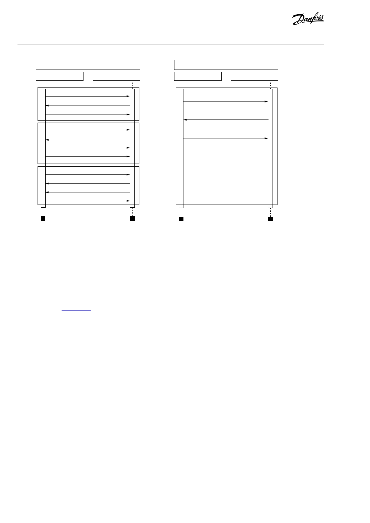
Illustration 1: Basic Structure of Modbus Frame
Introduction
On simple interfaces like RS485, the Modbus messages are sent in plain form over the network. In this case, the network is dedicated
to Modbus. When using more versatile network systems like TCP/IP over Ethernet, the Modbus messages are embedded in packets
with the format necessary for the physical interface. In that case Modbus and other types of connections can co-exist at the same
physical interface at the same time. Although the main Modbus message structure is peer-to-peer, Modbus is able to function on
both point-to-point and multidrop networks.
Each Modbus message has the same structure. Four basic elements are present in each message. The sequence of these elements is
the same for all messages, to make it easy to parse the content of the Modbus message. In the Modbus network, the master always
starts the conversation. A Modbus master sends a message and depending on the contents of the message, a slave reacts to it.
There can be more than one master in a Modbus network. Addressing in the message header is used to dene which device must
respond to a message. If the address eld does not match their own address, all other nodes on the Modbus network ignore the
message.
Modbus UDP vs TCP
In addition to TCP, the option boards also support UDP (from OPTE9 rmware version V006). We recommend using UDP when reading and writing rapidly and repetitively (cyclically) same data as with process data. Use TCP for single operations, like service data
(for example, reading or writing parameter values).
The main dierence between UDP and TCP is that when using TCP, the receiver must acknowledge every Modbus frame (see Illustra-
tion 2). It adds extra trac to the network and more load to the system (PLC and drives) because software must follow sent frames
to make sure that they have reached their destination.
BC346130105092EN-US-000101 / DPD01583 | 13Danfoss A/S © 2020.06
Page 14
Modbus TCP Communication
PLC
Open
Connection
Communicate
Communicate
Close
Connection
Drive
TCP, SYN
TCP, SYN, ACK
TCP, ACK
Modbus Query
Modbus Query
Modbus Response, TCP, ACK
TCP, ACK
TCP, ACK
TCP, ACK
TCP, ACK
TCP, FIN, ACK
Modbus UDP Communication
PLC Drive
Modbus Query
Modbus Response
Modbus Query
e30bh930.10
VACON® OPTEA/OPTE9 Ethernet Board
User Guide
Introduction
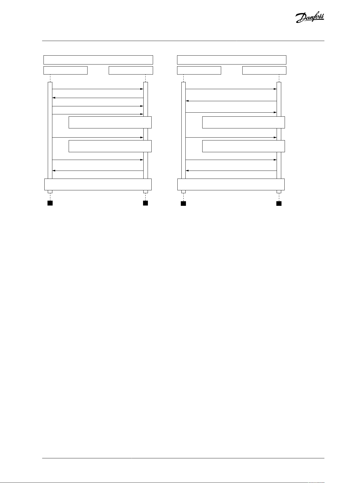
Illustration 2: Modbus TCP and UDP Communication Comparison
Another dierence between TCP and UDP is that UDP is connectionless. TCP connections are always opened with TCP SYN messages and closed with TCP FIN or TCP RST. With UDP, the rst packet is already a Modbus query. The option board treats IP address and
port combination as a connection. If port changes, it is considered as a new connection or as a second connection if both stay active.
When using UDP, it is not guaranteed that the sent frame reaches is destination. PLC must follow the Modbus requests by using the
Modbus transaction id-eld. It actually must do it also when using TCP. If PLC does not receive response in time from drive in UDP
connection, it must send the query again. When using TCP, the TCP/IP stack keeps resending the request until receiver has acknowledged it (see Illustration 3). If PLC sends new queries during this time, some of them can not be sent to network (by TCP/IP stack)
until previous sent package(s) has been acknowledged. It can cause small packet storms when the connection is resumed between
PLC and drive (See Illustration 4).
BC346130105092EN-US-000101 / DPD0158314 | Danfoss A/S © | 2020.06
Page 15
Modbus TCP Communication
PLC Drive
Modbus Query (1)
Modbus Query (2)
Modbus Response (1), TCP, ACK
Modbus Response (2), TCP, ACK
TCP, ACK
TCP retransmission, Modbus Query (2)
TCP retransmission, Modbus Query (2)
Normal communication continues
Packet lost, no response
Packet lost, no response
Modbus Query (1)
Modbus Response (1)
Modbus Response (4)
Modbus Query (2)
Modbus Query (3)
Modbus Query (4)
Packet lost, no response
Packet lost, no response
Normal communication continues
Modbus UDP Communication
PLC Drive
e30bh931.10
VACON® OPTEA/OPTE9 Ethernet Board
User Guide
Introduction
Illustration 3: Modbus TCP and UDP Communication Errors Comparison
BC346130105092EN-US-000101 / DPD01583 | 15Danfoss A/S © 2020.06
Page 16
e30bh932.10
Modbus TCP Communication
PLC Drive
Modbus Modbus
TCP
stack
TCP
stack
Modbus Query (1)
Modbus Query (2)
Modbus Query (3)
Modbus Query (4)
Modbus Query
(1,2,3)
Modbus Query (4)
Modbus Response (1,2,3)
Modbus Response (4)
TCP Modbus Query
TCP, ACK
TCP, ACK
TCP, ACK
TCP, ACK
TCP, Modbus Response (1,2,3)
TCP, Modbus Response (4)
TCP, Modbus Query (4)
Retransmission
Modbus Query (1,2,3)
Retransmission Modbus Query (1,2,3)
Retransmission
Modbus Query (1,2)
Retransmission
Modbus Query (1)
Modbus
Response (1,2,3)
Modbus
Response (4)
Normal communication continues
Packet lost
VACON® OPTEA/OPTE9 Ethernet Board
User Guide
Introduction
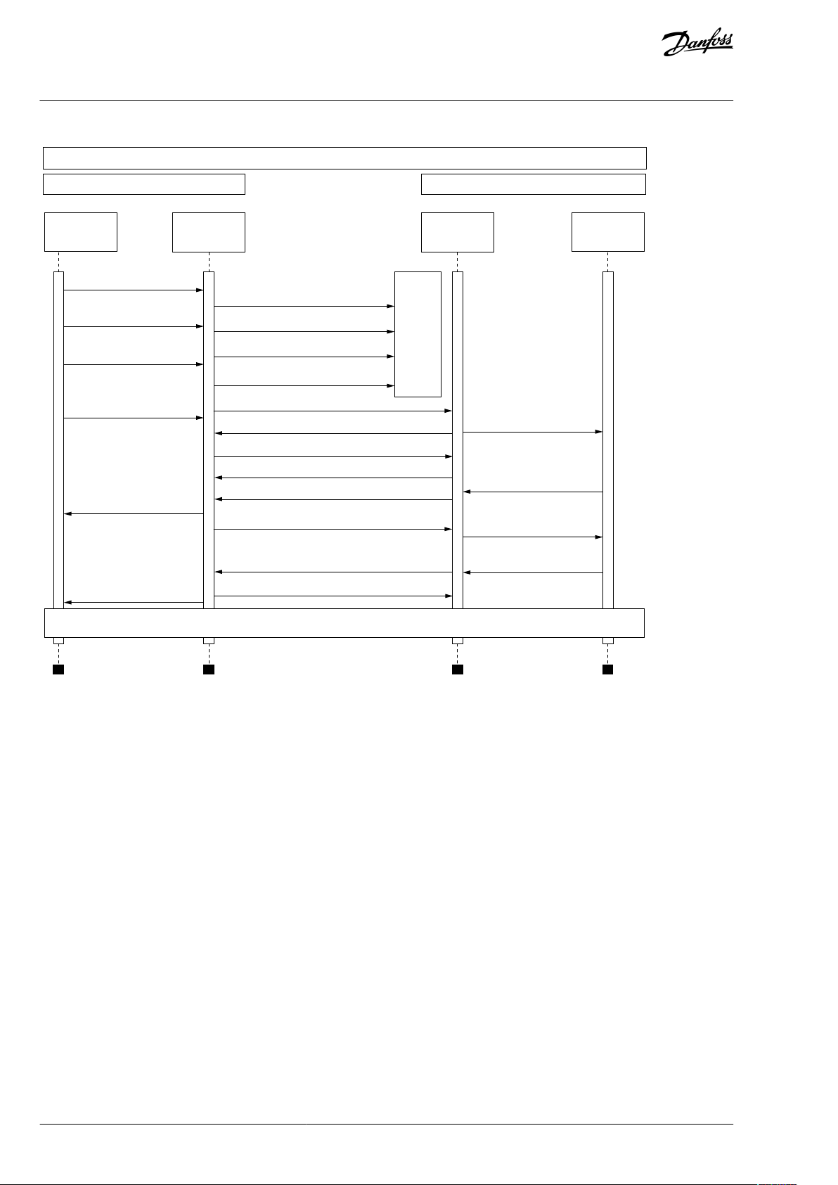
Illustration 4: Modbus TCP Retransmissions
Losing one packet is not a fatal because the same request can be sent again after timeout. In TCP, the packages always reach their
destination but if network congestion causes retransmissions, those packages contain most likely old data or instructions when they
reach their destination.
1.6.2.2 PROFINET I/O
PROFINET is the Ethernet-based automation standard of PROFIBUS International for the implementation of an integrated and consistent automation solution based on Industrial Ethernet. PROFINET supports the integration of simple distributed eld devices and
time-critical applications in (switched) Ethernet communication. It also supports the integration of component-based distributed
automation systems for vertical and horizontal integration of networks.
The option boards implement the following features:
•
PROFINET I/O version 2.4
•
PROFINET RT
•
Conformance class B (PA)
•
Highest netload class (class III)
•
Standard diagnosis for VACON® AC drive faults and alarms
The Advanced Dual Port Ethernet option board (OPTEA) implements also
BC346130105092EN-US-000101 / DPD0158316 | Danfoss A/S © | 2020.06
Page 17
PLC
Managed switch with RSTP support
DRIVE
OPTE9-1
DRIVE
...
OPTE9-2
DRIVE
OPTE9-3
DRIVE
OPTE9-8
1 2
DP AP
3 4 5 6 7 8
Power
e30bh922.10
VACON® OPTEA/OPTE9 Ethernet Board
User Guide
•
PROFINET system redundancy (S2)
•
PROFIsafe over PROFINET
•
OPTCP-emulation (OPTCx) mode when installed to VACON® NXP
•
Shared Device
Introduction
1.6.2.3 EtherNet/IP
The EtherNet/IP© is an industrial Ethernet network solution available for manufacturing automation. The CIP© (Common Industrial
Protocol) encompasses a comprehensive suite of messages and services for various manufacturing automation applications, including control, safety, synchronization, motion, conguration, and information. The CIP provides users with a unied communication
architecture throughout the manufacturing enterprise.
More information on the EtherNet/IP can be found at http://www.odva.org.
1.6.3 Redundancy Protocols
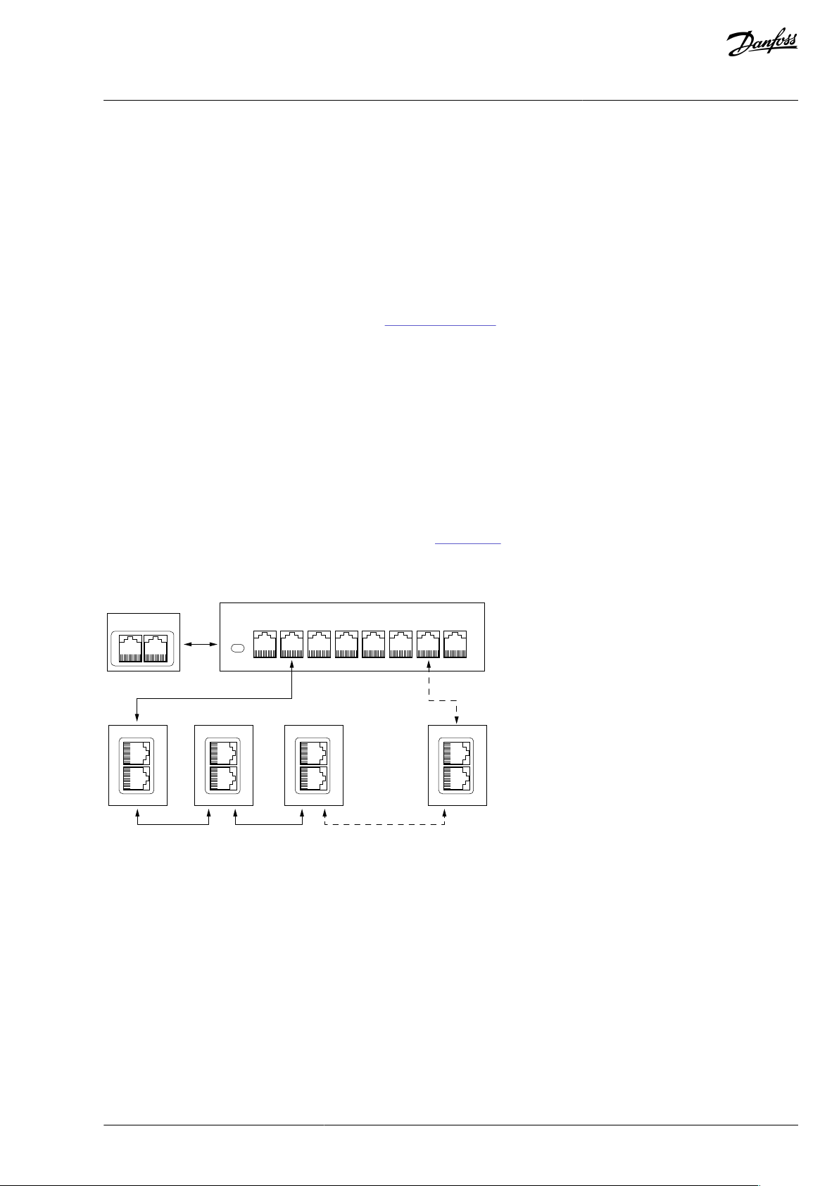
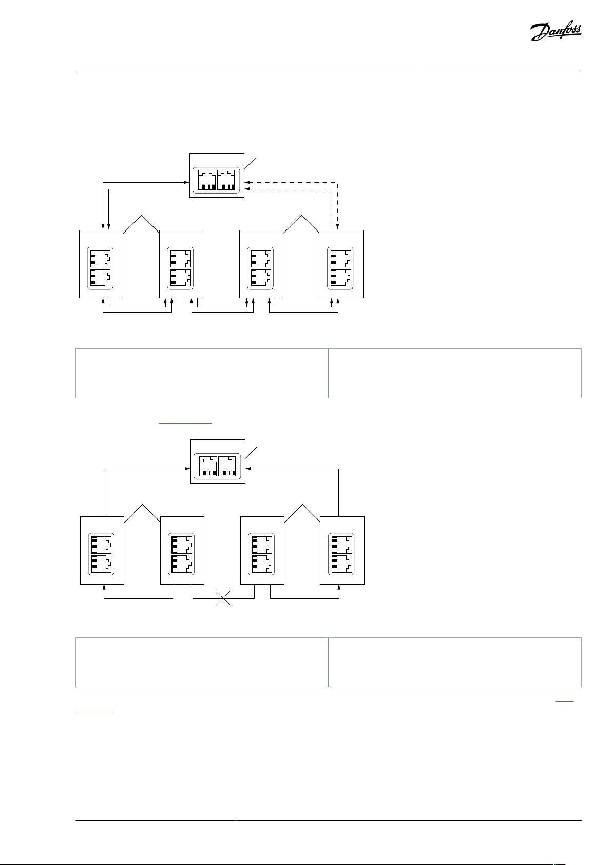
1.6.3.1 Rapid Spanning Tree Protocol (RSTP)
To use the RSTP protocol, add a managed Ethernet switch that supports the RSTP protocol. If a single link is broken, the RSTP switch
notices it and start sending data from the PLC to both directions eectively creating two daisy chains. When the link has been repaired, the switch notices it, too, and reverts to normal operating mode. Compared to the star topology, the ring topology adds
more network trac to almost all drives. Damage to two cables always creates an isolated subnetwork.
In the RSTP conguration, one of the ports in the switch is "Designated Port" (DP) and the other "Alternative Port" (AP). When the
network is functioning properly, the trac ows through the designated port. Only the BPDU (Bridge Protocol Data Unit) packets
are transferred through the AP port. The BPDU packets are used by the switch to determine if the network is working properly. If it
detects that the BPDU packets do not go through the ring, it changes the alternative port to a second designated port. Now the
switch sends packets to both directions in the broken ring (see Illustration 6).
Each designated port has a list of MAC addresses which are behind that port. Only frames directed to the device in the MAC list are
forwarded into that designated port. The broadcast and multicast frames are sent to all designated ports.
Illustration 5: Ring Topology
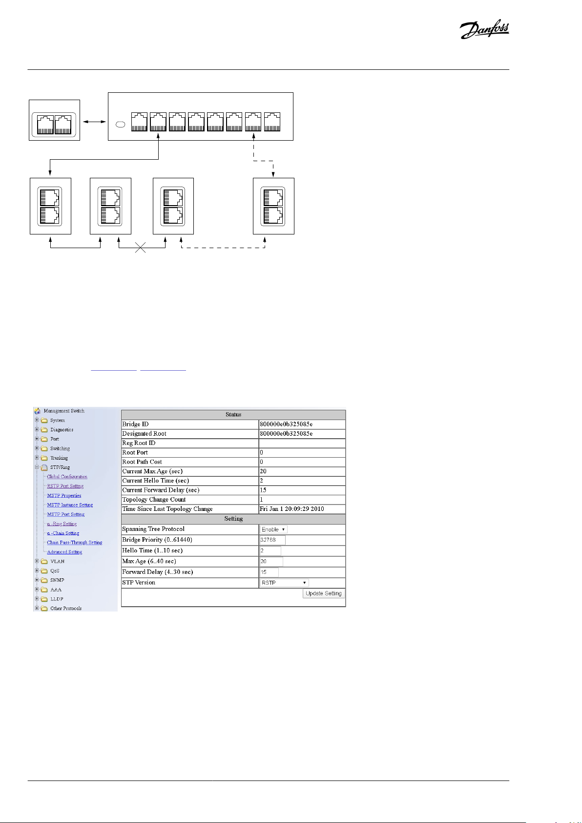
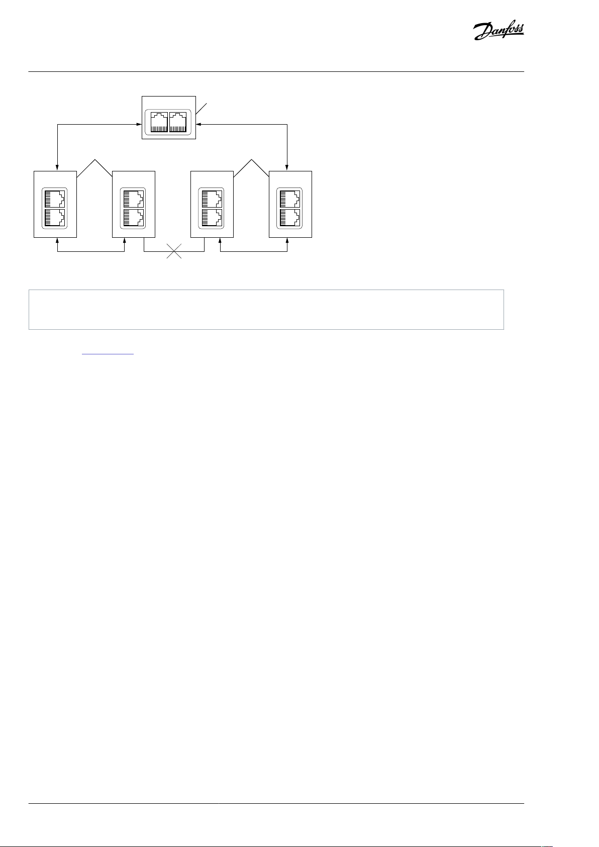
In the example below, the Ethernet communication is interrupted to device number 3 and other devices after that when the link is
broken. The Fieldbus communication maybe faulted when the link is broken, but when the switch enables the second designated
port, the connections can be reopened. In the RSTP protocol, it generally takes few seconds before the second designated port is
activated. The time depends on the BPDU exchange cycle, which is 2 seconds by default.
BC346130105092EN-US-000101 / DPD01583 | 17Danfoss A/S © 2020.06
Page 18
PLC
Managed switch with RSTP support
DRIVE
OPTE9-1
DRIVE
...
OPTE9-2
DRIVE
OPTE9-3
DRIVE
OPTE9-8
1 2
DP DP
3 4 5 6 7 8
Power
e30bh923.10
e30bh924.10
VACON® OPTEA/OPTE9 Ethernet Board
User Guide
Introduction
Illustration 6: Ring Topology: Error in Network
NOTE! The switch itself in Ethernet boards does not implement the RSTP protocol, so the network always needs a third party switch
to support it.
NOTE! Do not use RSTP together with PROFIsafe. Recovery time in RSTP network can be several seconds, and recovery time in STP
network can be several tens of seconds. To compensate the recovery time, the PROFIsafe watchdog time must be set long enough
so that slow recovery time of RSTP network can be tolerated. However, for example, in Siemens TIA portal, the longest PROFIsafe
watchdog time setting is 1920 ms, and it is too short for RSTP.
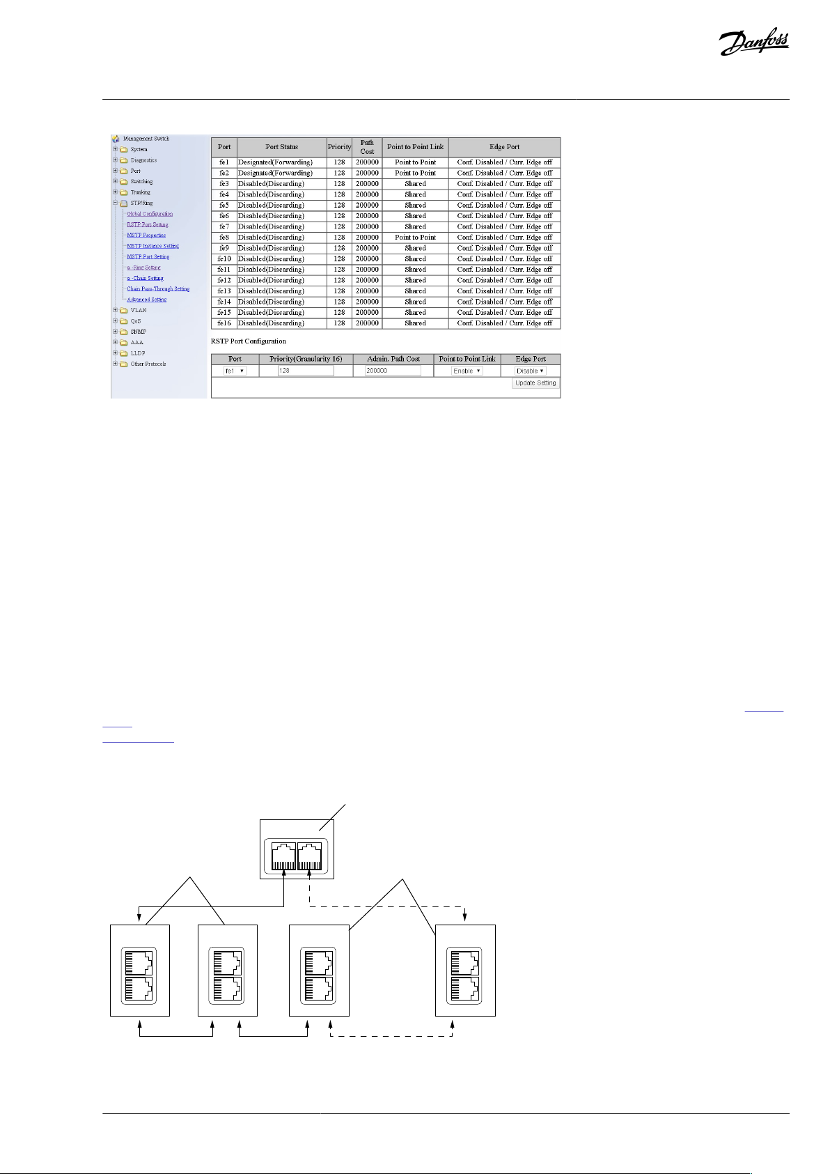
Conguration Example
The screenshots (
Illustration 7, Illustration 8) show one example of conguring the RSTP in the switch (in this case an EtherWAN
switch). Port two is the designated port and port one is the alternative port. The PLC was connected to port nine (the laptop taking
the screenshots was in port 16). When conguring your switch, refer to the manual of the switch manufacturer.
Illustration 7: EtherWAN Switch RSTP Conguration Example
BC346130105092EN-US-000101 / DPD0158318 | Danfoss A/S © | 2020.06
Page 19
e30bh925.10
OPTE9-1
...
OPTE9-2 OPTE9-3 OPTE9-8
1
2
2
e30bh927.10
VACON® OPTEA/OPTE9 Ethernet Board
User Guide
Illustration 8: EtherWAN Switch RSTP Conguration Example - Port Settings
Introduction
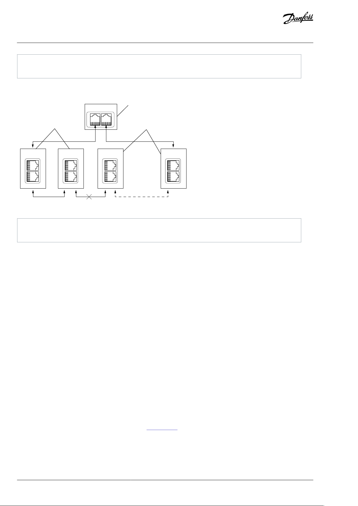
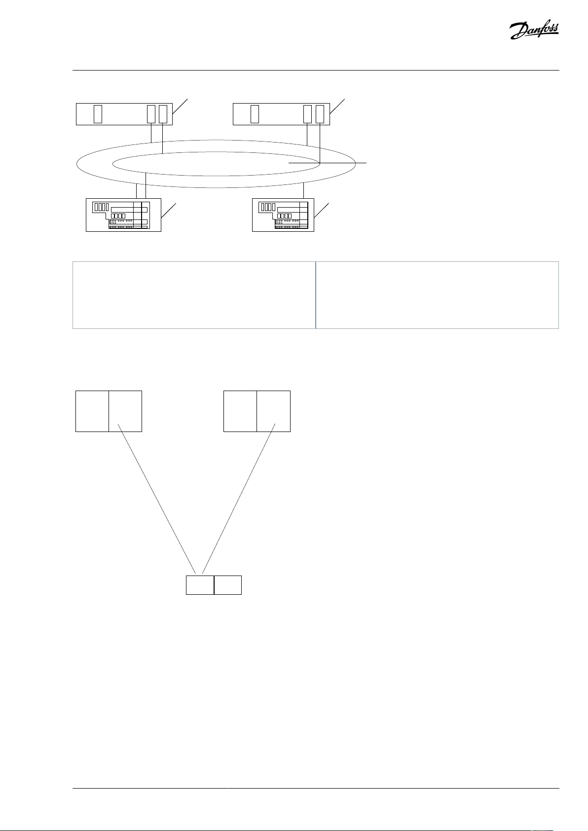
1.6.3.2 Media Redundancy Protocol (MRP)
The MRP is designed to react deterministically on a cable failure. It makes it suitable to be used in process automation. One of the
nodes in the network has the role of Media Redundancy Master (MRM), which observes and controls the ring topology to react to
network faults. Usually this device is PLC or network switch.
Other nodes in the network are called Media Redundancy Clients (MRC), and they react on received conguration frames from the
MRM and can detect link changes on its ring ports. OPTEA and OPTE9 boards support only MRC functionality.
The MRM and MRC have two ring ports, which take one of the following states:
•
DISABLED - All frames are dropped
•
BLOCKING - All frames are dropped, except the following frames:
-
MRP frames (for example, MRP_test and MRP_TopologyChange)
-
Frames specied to pass ports in "Discarding" state, for example, LLDP frames
•
FORWARDING - All frames are forwarded according to normal behavior
The MRM sends MRP_Test frames in a congured time period to monitor the state of the ring topology. If the MRM receives its own
MRP_Test frames (network is closed), one of the ring ports is set to FORWARDING state and the other to BLOCKED state (see Illustra-
tion 9). If the MRM does not receive the MRP_Test frames (network is open), it sets both of its ring ports to FORWARDING state (see
Illustration 10).
The following gure shows an example of an MRP network, where the PLC acts as an MRM. The dotted line shows Blocked connection.
Illustration 9: MRP Ring: Closed Network
BC346130105092EN-US-000101 / DPD01583 | 19Danfoss A/S © 2020.06
Page 20
1
PLC/MRM
2
Drive/MRC
OPTE9-1
...
OPTE9-2 OPTE9-3 OPTE9-8
e30bh928.10
1
2
2
1
PLC/MRM
2
Drive/MRC
VACON® OPTEA/OPTE9 Ethernet Board
User Guide
Introduction
In the example below, the Ethernet communication is interrupted to device number 3 and other devices after that when the link is
broken.
Illustration 10: MRP Ring: Error in Network
NOTE! MRP (as MRC) can only be used when PROFINET is the selected protocol. MRP is available in all versions of OPTEA board and
in OPTE9 since V006 rmware.
MRP Recovery Times and Fast MRP
MRP can be congured to send test frames with dierent time periods, depending on the maximum allowed recovery time for the
network. These times are set as the guaranteed time for a network of 50 nodes to recover from a ring error.
Typically, in PROFINET systems the recovery time is dened as 200 ms. However, the MRP specication allows for recovery times of
500, 200, 30, and 10 ms. OPTEA and OPTE9 boards can be used in systems with the lowest recovery time of 10 ms. It is often called
“Fast MRP”.
When using MRP in a PROFINET network, the recommendation is to set the watchdog time of each device in the ring to the maximum recovery time, usually 200 ms. It guarantees that a cable failure does not interrupt the eldbus connection.
1.6.3.3 Device Level Ring (DLR)
Device Level Ring (DLR) protocol provides a way to detect, manage, and recover from faults in a ring-based network. It supports a
single-ring topology. Multiple or overlapping rings are not supported. Other features include "Sign on process" used to identify all
ring participants, and "Neighbor check process" which allows nodes to check the health of their adjacent nodes.
One device acts as a ring supervisor, monitoring the state of the ring while other devices act as DLR nodes. Only one device can act
as an active supervisor, although back-up supervisors are possible. Nodes can be divided into Beacon- and Announce-based nodes
depending on which frames the nodes process. OPTEA and OPTE9 boards support Announce-based functionality.
DLR nodes have three states:
•
IDLE_STATE: indicating linear topology for non-supervisor nodes
•
FAULT_STATE: initial state for enabled ring supervisor, or when ring fault has been detected
•
NORMAL_STATE: normal function in ring topology mode
The active ring supervisor sends Beacon frames from both its ring ports once per beacon interval (400 μs by default) to monitor the
state of the ring. It also sends an Announce frame once per s. If the Beacon frames are received back at the supervisor, one of its
ports is set to blocking and the other to forwarding state (Illustration 11). Only the following packets are processed from the blocked
port:
BC346130105092EN-US-000101 / DPD0158320 | Danfoss A/S © | 2020.06
Page 21
e30bh975.10
1
2 2
3
3
4
4
OPTE9-1 OPTE9-2
OPTE9-3 OPTE9-4
1
Ring Supervisor
2
DLR Node
3
Beacon
4
Announce
OPTE9-1 OPTE9-2
OPTE9-3 OPTE9-4
e30bh976.10
2
3
3
2
1
1
Active Ring Supervisor
2
DLR Node
3
Link Status
VACON® OPTEA/OPTE9 Ethernet Board
User Guide
•
Beacon frames from self and other supervisors
•
Link_Status/Neighbor_Status frames
•
Neighbor_Check request or response and Sign_On frames
Illustration 11: DLR Ring: Network Conguration when Ring is Closed (NORMAL_STATE)
Introduction
If a network error occurs to DLR-capable nodes, the nodes send Link_Status frames to inform the ring supervisor immediately which
port(s) have a failure (Illustration 12).
Illustration 12: DLR Ring: Failure in Network
A Link_Status frame triggers an error response in active ring supervisor, which unblocks trac on its previously blocked port (Illus-
tration 13). If there is an uncommon failure (for example, if a cable breaks between two non-DLR capable devices), the error is no-
ticed from Beacon timeout value, and not from Link_Status frames. Therefore, a recovery in a network with non-DLR capable devices
can take longer.
BC346130105092EN-US-000101 / DPD01583 | 21Danfoss A/S © 2020.06
Page 22
OPTE9-1 OPTE9-2
OPTE9-3 OPTE9-4
1
2 2
e30bh977.10
1
Active Ring Supervisor
2
DLR Node
VACON® OPTEA/OPTE9 Ethernet Board
User Guide
Illustration 13: DLR Ring: Network Conguration after Failure (FAULT_STATE)
Introduction
The ring recovers after Beacon frames again are received from both of the active ring supervisors ring ports. Ring recovers back to its
original state (Illustration 11).
NOTE! DLR is active only when EtherNet/IP is the selected protocol. DLR is available since V002 rmware for OPTEA and since V009
rmware for OPTE9 board.
DLR Recovery Times
DLR allows setting of the beacon interval and the beacon timeout values, with lower beacon interval providing faster ring recovery
performance. With default values (400 μs interval and 1960 μs timeout), DLR can reach much faster ring recovery times than, for
example, Media Redundancy Protocol. Typically, these times are around 3 ms for Beacon-based and 4 ms for Announce-based nodes.
When using DLR, we recommend that the watchdog time is set to a value greater than 4 ms. It ensures that a properly congured
ring network recovers from a network failure within the watchdog time.
1.6.3.4 PROFINET System Redundancy (OPTEA)
Redundancy is a requirement in process automation systems for high availability and reduced production downtimes. PROFINET
System Redundancy provides a solution to build a system with redundant PN controllers, devices, and communication.
PROFINET System Redundancy fullls among others the following requirements:
Highly reliable communication
•
Short take over time
•
Bumpless I/O data during fault recovery
•
Monitoring of the back-up connection
•
System redundancy implements two redundant PN controllers, one working as primary and other as back-up. These controllers can
be connected via a redundant network to PN devices. It is, however, not mandatory as system redundancy has dierent levels which
are independent from each other. Thus, PN controller, Ethernet media, and PN device can have dierent redundancy congurations.
BC346130105092EN-US-000101 / DPD0158322 | Danfoss A/S © | 2020.06
Page 23
1
2
3
45
e30bh978.10
1
Primary
2
Back-up
3
Redundant network
4
Device with redundant connectivity
5
Device with singular connectivity
Host
NAP IO
IOC
PROFINET
SR-ARa
Single NAP
S2
SR-ARb
IOC
Host
e30bh979.10
VACON® OPTEA/OPTE9 Ethernet Board
User Guide
Illustration 14: System Redundancy Overview
Introduction
OPTEA supports "S2" level of System Redundancy and Media Redundancy Protocol (MRP) for redundant connectivity.
S2 uses a single PROFINET interface (NAP = Network Access Point), and two SR-ARs (System Redundancy Application Relations =
connections), one to each PN controller. Redundant PN controllers have parallel access to an SR PN device, but only one AR acts as a
primary (SR-ARa) and the other is back-up (SR-ARb).
Illustration 15: NAP S2, Connected to 2 IOCs
In case the primary AR fails, the IOC initiates a switch for the back-up SR-AR to become primary. This switchover cannot take longer
than the Redundancy Data Hold Time (RDHT) congured by the IOC. During the transition, the input data is hold and the output
data frozen to ensure a bumpless transition. OPTEA does not create a fault during this time when a back-up connection is available.
A fault is created after this time elapses and no Primary is available.
NOTE! System Redundancy is available in OPTEA version V002 or later and requires the use of GSDML le dated 21.06.2018 or later.
1.6.4 PROFINET Shared Device (OPTEA)
OPTEA supports Shared Device feature where multiple PLCs can connect to same device. PLC A can connect to PROFIdrive module
and PLC B can connect to PROFIsafe module. It is also possible to have System Redundancy connections (two PLCs) and PROFIsafe
from third PLC at the same time.
This kind of setup generates up to three times more Ethernet trac than connecting with single PLC, so consider the cycle times
and number of devices in the system. Connections to multiple PROFIdrive or PROFIsafe modules are not supported.
BC346130105092EN-US-000101 / DPD01583 | 23Danfoss A/S © 2020.06
Page 24

Technical item or function
Technical data
General
Board name
OPTEA/OPTE9
Ethernet connections
Interface
Two RJ-45 connectors
Transfer cable
Shielded Twisted Pair (STP) CAT5e
(1)
Communications
Speed
10 / 100 Mb
Duplex
half / full
Default IP-address
By default the board is in DHCP mode.
Protocol
Modbus TCP, Modbus UDP, Pronet I/O, EtherNet/IP
Environment
Ambient operating temperature
-10°C…50° C
Storing temperature
-40°C…70° C
Humidity
<95%, no condensation allowed
Altitude
Maximum 1000 m
Vibration
0.5 G at 9…200 Hz
Safety
Fullls EN 50178 standard
VACON® OPTEA/OPTE9 Ethernet Board
User Guide
Shared device feature also enables adding of PROFIsafe to existing systems. Notice that PROFIsafe has its own conguration requirements (see 4.5 PROFIsafe (OPTEA)).
Introduction
1.6.5 Address Conict Detection (ACD)
The OPTEA and OPTE9 option boards implement ACD algorithm (IETF RFC 5227). The implementation includes requirements from
the EtherNet/IP protocol.
The ACD algorithm tries to detect actively if another device is using the IP address in the same network. The ACD sends 4 ARP request packets when the Ethernet interface of the device activates, or when its IP address changes.
ACD prevents the use of the Ethernet interface until the ARP probing nishes. This delays the start-up of eldbus protocols about 1
s. During the delay or after it, the ACD passively checks incoming ARP messages for use of the IP address of the device.
If another device with the same IP address is detected, the ACD tries to defend its IP address with a single ARP message. If the other
device with the same IP address also supports ACD, it must stop using the address. If it does not, the ACD closes the Ethernet connection and indicates the situation with LEDs. This is done according the "DefendWithPolicyB". Other policies are not supported.
If the eldbus protocol has been active, it can activate a eldbus fault (depends on the eldbus and drive application conguration).
1.6.6 Technical Data
Table 2: OPTEA/OPTE9 Option Board Technical Data
1
For connecting the eldbus Ethernet boards, use only Ethernet cables that meet at least the requirements of category 5 (CAT5) according to EN
50173 or ISO/IEC 11801.
1.6.7 VACON® PC Tools
With VACON® PC tools, it is possible to do following operations for OPTEA/OPTE9 Ethernet board:
Update rmware into OPTEA/OPTE9 board (with VACON® Loader), see
•
•
Set parameters for OPTEA/OPTE9 Ethernet board (with VACON® NCDrive or VACON® Live), see 3.2.4.1 Setting the Drive Parame-
ters with VACON® NCDrive and 3.2.4.2 Setting the Drive Parameters with VACON® Live
•
Read monitor values of OPTEA/OPTE9 Ethernet board (with VACON® NCDrive or VACON® Live)
For instructions on downloading and installing the tools, see 3.1.1 Installing VACON® PC Tools.
The following table describes what PC tools are supported in each AC drive type.
3.2.1 Updating Fieldbus Firmware with VACON® Loader
BC346130105092EN-US-000101 / DPD0158324 | Danfoss A/S © | 2020.06
Page 25

Tool
VACON® 100 family
VACON® NXS/NXP
VACON® 20 family
VACON® Loader
Serial
(1)
Serial
(1)
Serial
(1)
VACON® Live
Serial
(1)
, Ethernet
(2)
-
Serial
(1)
VACON® NCIPCong
Ethernet
(2)
Ethernet
(2)
Ethernet
(2)
VACON® NCDrive
-
Ethernet
(2)
-
VACON® NCLoad
Not supported; use VACON® Loader.
AC drive
Slots
From AC drive software version on
From OPTEA software version on
VACON® NXP
D, E
NXP00002V196
V001
VACON® NXS
D, E
NXS00002V184
V003
VACON® 100 INDUSTRIAL
and 100 X
D, E
FW0072V028
V002
VACON® 100 FLOW
D, E
FW0159V018
V002
AC Drive
From AC drive software version on
VACON® NXP
NXP00002V197
VACON® 100 INDUSTRIAL and 100 X
FW0072V028
VACON® 100 FLOW
FW0159V018
VACON® OPTEA/OPTE9 Ethernet Board
User Guide
Table 3: The Supported PC Tools with Dierent AC Drives
1
The connection type "serial" is a direct serial connection to the AC drive.
2
The connection type "Ethernet" is an Ethernet connection, for example, VACON® 100 family built-in Ethernet interface, or a connection via OPTEA/
OPTE9 Dual Port Ethernet option board.
Introduction
1.7 AC Drive Support
1.7.1 VACON® OPTEA Advanced Dual Port Ethernet Drive Support
The VACON® OPTEA Advanced Dual Port Ethernet option board can be used with the following VACON® AC drives. Option board
can be used for PROFINET with PROFIsafe communication in slot E, when OPTBL/OPTBM/OPTBN is installed to slot D. If PROFIsafe is
not used, then OPTEA can be installed to slot D too.
Table 4: OPTEA-supported AC Drives and Slots
VACON® 100 Family Support
The VACON® 100 family AC drives are supported from the OPTEA rmware version V002. The process data in VACON® 100 family AC
drives is 32 bit. PROFIsafe features are supported only in VACON® NXP drives.
EtherNet/IP and Modbus TCP/UDP Support
Support for EtherNet/IP, Modbus TCP/UDP, and other features which were in OPTE9, were added to OPTEA rmware V002. Table
below shows required minimum AC drive rmware version.
Table 5: Required Minimum AC Drive Firmware Versions
1.7.2 VACON® OPTE9 Dual Port Ethernet Drive Support
The VACON® OPTE9 Dual Port Ethernet option board can be used with the following VACON® AC drives.
BC346130105092EN-US-000101 / DPD01583 | 25Danfoss A/S © 2020.06
Page 26

AC drive
Slots
From AC drive software version on
From OPTE9 software version on
VACON® NXP
D, E
NXP00002V188
V001
VACON® NXS
D, E
NXS00002V179
V001
VACON® 100 INDUSTRIAL and 100 X
D, E
FW0072V018
V003
VACON® 100 FLOW
D, E
FW0159V012
V003
VACON® 20
-
FW0107V011
V002
VACON® 20 X and CP
-
FW0117V007
V002
AC Drive
From AC drive SW version on
VACON® NXP
NXP00002V191
VACON® NXS
NXS00002V181
VACON® 100 INDUSTRIAL and 100 X
FW0072V018
VACON® 100 FLOW
FW0159V012
VACON® 20
FW0107V012
VACON® 20 X and CP
FW0117V009
Abbreviation
Denition
ACD
Address Conict Detection
ARP
Address Resolution Protocol
CIP
Common Industrial Protocol
CRC
Cyclic Redundancy Check is an error-detecting code commonly used in eldbusses to detect accidental
changes to raw data.
CW
Control word
DCP
Discovery and Basic Conguration Protocol
DHCP
Dynamic Host Conguration Protocol is used for dynamical resolving of network conguration parameters
like an IP address.
DLR
Device Level Ring
DU
Data unit
EDD
Electronic Device Description
VACON® OPTEA/OPTE9 Ethernet Board
User Guide
Table 6: OPTE9-supported AC Drives and Slots
VACON® 100 Family Support
The VACON® 100 family AC drives are supported from the OPTE9 rmware version V003. The process data in VACON® 100 family AC
drives is 32 bit.
EtherNet/IP and Modbus TCP/UDP Support
EtherNet/IP protocol was added to OPTE9 rmware version V004. The following table shows required minimum AC drive rmware
version.
Table 7: Required Minimum AC Drive Firmware Versions
Introduction
1.8 Symbols and Abbreviations
Table 8: Symbols and Abbreviations
BC346130105092EN-US-000101 / DPD0158326 | Danfoss A/S © | 2020.06
Page 27

Abbreviation
Denition
EDS
Electronic Data Sheet
EMC
Electromagnetic compatibility
FB
Fieldbus
FD
Full Duplex
GSDML
General Station Description Markup Language
GW
Gateway
HD
Half Duplex
HI
Upper 8/16 bits in a 16/32-bit value.
LED
Light emitting diode
LLDP
Link Layer Discovery Protocol
LO
Lower 8/16 bits in a 16/32-bit value.
MIB
Management Information Base
Modbus TCP /
Modbus UDP
Simple and vendor-neutral communication protocol intended for monitoring and controlling of eld devices.
MRC
Media Ring Client
MRM
Media Ring Master
MRP
Media Ring Protocol
NSOLL
Sollwert (German for reference value)
NIST
Istwert (German for actual value)
PC
Personal computer
PDI
Process Data In
PDO
Process Data Out
PHY(X)
Ethernet physical interface X, where X shows the number of interfaces
PLC
Programmable logic controller
PNU
Parameter number
PPO
Process parameter object
PROFINET I/O
PROFINET is a standard for industrial automation in Ethernet network. PROFINET I/O describes the exchange of data between controllers and eld devices.
RDHT
Redundancy Data Hold Time
RPM
Revolutions per minute
RSTP
Rapid Spanning Tree Protocol
SNMP
Simple Network Management Protocol
SNTP
Simple Network Time Protocol
VACON® OPTEA/OPTE9 Ethernet Board
User Guide
Introduction
BC346130105092EN-US-000101 / DPD01583 | 27Danfoss A/S © 2020.06
Page 28

Abbreviation
Denition
STW1
Steuerwort 1 (German for control word 1)
SW
Status word
TCP
Transmission Control Layer provides reliable, ordered, and error-checked delivery of data streams between
computers that are connected to a local area network.
UTC
Coordinated Universal Time
ZSW1
Zustandwort 1 (German for status word 1)
Type name
Bit size
Explanation
INT88Signed short integer
UINT8
8
Unsigned short integer
INT16
16
Signed integer
UINT16
16
Unsigned integer
INT32
32
Signed long integer
UINT32
32
Unsigned long integer
FLOAT32
32
32-bit oating point
STRING3
24
3 byte string
STRING5
40
5 byte string
VACON® OPTEA/OPTE9 Ethernet Board
User Guide
Table 9: Data Types
Introduction
BC346130105092EN-US-000101 / DPD0158328 | Danfoss A/S © | 2020.06
Page 29

VACON® OPTEA/OPTE9 Ethernet Board
User Guide
2 Safety
2.1 Safety Symbols
The following symbols are used in this manual:
D A N G E R
Indicates a hazardous situation which, if not avoided, will result in death or serious injury.
W A R N I N G
Indicates a hazardous situation which, if not avoided, could result in death or serious injury.
C A U T I O N
Indicates a hazardous situation which, if not avoided, could result in minor or moderate injury.
N O T I C E
Indicates information considered important, but not hazard-related (for example, messages relating to property damage).
Safety
2.2 Danger and Warnings
D A N G E R
SHOCK HAZARD FROM POWER UNIT COMPONENTS
The power unit components are live when the drive is connected to mains. A contact with this voltage can lead to death or seri-
ous injury.
Do not touch the components of the power unit when the drive is connected to mains. Before connecting the drive to mains,
-
make sure that the covers of the drive are closed.
D A N G E R
SHOCK HAZARD FROM TERMINALS
The motor terminals U, V, W, the brake resistor terminals, or the DC terminals are live when the drive is connected to mains, also
when the motor does not operate. A contact with this voltage can lead to death or serious injury.
Do not touch the motor terminals U, V, W, the brake resistor terminals, or the DC terminals when the drive is connected to
-
mains. Before connecting the drive to mains, make sure that the covers of the drive are closed.
D A N G E R
SHOCK HAZARD FROM DC LINK OR EXTERNAL SOURCE
The terminal connections and the components of the drive can be live 5 minutes after the drive is disconnected from the mains
and the motor has stopped. Also the load side of the drive can generate voltage. A contact with this voltage can lead to death or
serious injury.
Before doing electrical work on the drive:
-
Disconnect the drive from the mains and make sure that the motor has stopped.
Lock out and tag out the power source to the drive.
Make sure that no external source generates unintended voltage during work.
Wait 5 minutes before opening the cabinet door or the cover of the AC drive.
Use a measuring device to make sure that there is no voltage.
BC346130105092EN-US-000101 / DPD01583 | 29Danfoss A/S © 2020.06
Page 30

VACON® OPTEA/OPTE9 Ethernet Board
User Guide
Safety
W A R N I N G
SHOCK HAZARD FROM CONTROL TERMINALS
The control terminals can have a dangerous voltage also when the drive is disconnected from mains. A contact with this voltage
can lead to injury.
Make sure that there is no voltage in the control terminals before touching the control terminals.
-
W A R N I N G
ACCIDENTAL MOTOR START
When there is a power-up, a power break, or a fault reset, the motor starts immediately if the start signal is active, unless the pulse
control for Start/Stop logic is selected. If the parameters, the applications or the software change, the I/O functions (including the
start inputs) can change. If you activate the auto reset function, the motor starts automatically after an automatic fault reset. See
the Application Guide. Failure to ensure that the motor, system, and any attached equipment are ready for start can result in
personal injury or equipment damage.
Disconnect the motor from the drive if an accidental start can be dangerous. Make sure that the equipment is safe to operate
-
under any condition.
W A R N I N G
LEAKAGE CURRENT HAZARD
Leakage currents exceed 3.5 mA. Failure to ground the drive properly can result in death or serious injury.
Ensure the correct grounding of the equipment by a certied electrical installer.
-
W A R N I N G
SHOCK HAZARD FROM PE CONDUCTOR
The drive can cause a DC current in the PE conductor. Failure to use a residual current-operated protective (RCD) device Type B or
a residual current-operated monitoring (RCM) device can lead to the RCD not providing the intended protection and therefore
can result in death or serious injury.
Use a type B RCD or RCM device on the mains side of the drive.
-
2.3 Cautions and Notices
C A U T I O N
DAMAGE TO THE AC DRIVE FROM INCORRECT MEASUREMENTS
Doing measurements on the AC drive when it is connected to mains can damage the drive.
Do not do measurements when the AC drive is connected to mains.
-
C A U T I O N
DAMAGE TO THE AC DRIVE FROM INCORRECT SPARE PARTS
Using spare parts that are not from the manufacturer can damage the drive.
Do not use spare parts that are not from the manufacturer.
-
C A U T I O N
DAMAGE TO THE AC DRIVE FROM INSUFFICIENT GROUNDING
Not using a grounding conductor can damage the drive.
Make sure that the AC drive is always grounded with a grounding conductor that is connected to the grounding terminal
-
that is identied with the PE symbol.
BC346130105092EN-US-000101 / DPD0158330 | Danfoss A/S © | 2020.06
Page 31

VACON® OPTEA/OPTE9 Ethernet Board
User Guide
C A U T I O N
CUT HAZARD FROM SHARP EDGES
There can be sharp edges in the AC drive that can cause cuts.
Wear protective gloves when mounting, cabling, or doing maintenance operations.
-
C A U T I O N
BURN HAZARD FROM HOT SURFACES
Touching surfaces, which are marked with the 'hot surface' sticker, can result in injury.
Do not touch surfaces which are marked with the 'hot surface' sticker.
-
N O T I C E
DAMAGE TO THE AC DRIVE FROM STATIC VOLTAGE
Some of the electronic components inside the AC drive are sensitive to ESD. Static voltage can damage the components.
Remember to use ESD protection always when working with electronic components of the AC drive. Do not touch the com-
-
ponents on the circuit boards without proper ESD protection.
Safety
N O T I C E
DAMAGE TO THE AC DRIVE FROM MOVEMENT
Movement after installation can damage the drive.
Do not move the AC drive during operation. Use a xed installation to prevent damage to the drive.
-
N O T I C E
DAMAGE TO THE AC DRIVE FROM INCORRECT EMC LEVEL
The EMC level requirements for the AC drive depend on the installation environment. An incorrect EMC level can damage the
drive.
Before connecting the AC drive to the mains, make sure that the EMC level of the AC drive is correct for the mains.
-
N O T I C E
RADIO INTERFERENCE
In a residential environment, this product can cause radio interference.
Take supplementary mitigation measures.
-
N O T I C E
MAINS DISCONNECTION DEVICE
If the AC drive is used as a part of a machine, the machine manufacturer must supply a mains disconnection device (refer to EN
60204-1).
N O T I C E
MALFUNCTION OF FAULT CURRENT PROTECTIVE SWITCHES
Because there are high capacitive currents in the AC drive, it is possible that the fault current protective switches do not operate
correctly.
BC346130105092EN-US-000101 / DPD01583 | 31Danfoss A/S © 2020.06
Page 32

Cross-sectional area of the phase conductors (S) [mm2]
The minimum cross-sectional area of the protective earthing conductor in question [mm2]
S ≤ 16
S
16 < S ≤ 35
16
35 < S
S/2
VACON® OPTEA/OPTE9 Ethernet Board
User Guide
N O T I C E
VOLTAGE WITHSTAND TESTS
Doing voltage withstand tests can damage the drive.
Do not do voltage withstand tests on the AC drive. The manufacturer has already done the tests.
-
2.4 Grounding
Ground the AC drive in accordance with applicable standards and directives.
C A U T I O N
DAMAGE TO THE AC DRIVE FROM INSUFFICIENT GROUNDING
Not using a grounding conductor can damage the drive.
Make sure that the AC drive is always grounded with a grounding conductor that is connected to the grounding terminal
-
that is identied with the PE symbol.
W A R N I N G
LEAKAGE CURRENT HAZARD
Leakage currents exceed 3.5 mA. Failure to ground the drive properly can result in death or serious injury.
Ensure the correct grounding of the equipment by a certied electrical installer.
-
Safety
The standard EN 61800-5-1 tells that 1 or more of these conditions for the protective circuit must be true.
The connection must be xed.
•
The protective earthing conductor must have a cross-sectional area of minimum 10 mm2 Cu or 16 mm2 Al. OR
•
There must be an automatic disconnection of the mains, if the protective earthing conductor breaks. OR
•
There must be a terminal for a second protective earthing conductor in the same cross-sectional area as the rst protective
earthing conductor.
The values of the table are valid only if the protective earthing conductor is made of the same metal as the phase conductors. If this
is not so, the cross-sectional area of the protective earthing conductor must be determined in a manner that produces a conductance equivalent to that which results from the application of this table.
The cross-sectional area of each protective earthing conductor that is not a part of the mains cable or the cable enclosure, must be a
minimum of:
•
2.5 mm2 if there is mechanical protection, and
•
4 mm2 if there is not mechanical protection. With cord-connected equipment, make sure that the protective earthing conductor
in the cord is the last conductor to be interrupted, if the strain-relief mechanism breaks.
Obey the local regulations on the minimum size of the protective earthing conductor.
N O T I C E
MALFUNCTION OF FAULT CURRENT PROTECTIVE SWITCHES
Because there are high capacitive currents in the AC drive, it is possible that the fault current protective switches do not operate
correctly.
BC346130105092EN-US-000101 / DPD0158332 | Danfoss A/S © | 2020.06
Page 33

VACON® OPTEA/OPTE9 Ethernet Board
User Guide
Safety
N O T I C E
VOLTAGE WITHSTAND TESTS
Doing voltage withstand tests can damage the drive.
Do not do voltage withstand tests on the AC drive. The manufacturer has already done the tests.
-
W A R N I N G
SHOCK HAZARD FROM PE CONDUCTOR
The drive can cause a DC current in the PE conductor. Failure to use a residual current-operated protective (RCD) device Type B or
a residual current-operated monitoring (RCM) device can lead to the RCD not providing the intended protection and therefore
can result in death or serious injury.
Use a type B RCD or RCM device on the mains side of the drive.
-
BC346130105092EN-US-000101 / DPD01583 | 33Danfoss A/S © 2020.06
Page 34

VACON® OPTEA/OPTE9 Ethernet Board
User Guide
Commissioning
3 Commissioning
3.1 Before Commissioning
VACON® OPTEA/OPTE9 Ethernet can be commissioned through the control panel of the AC drive or by using the VACON® PC tools.
Before starting the commissioning, check the following:
•
When using the control panel of the AC drive for commissioning: for instructions on how to use the control panel, see the Operating Guide for VACON® NXP products or the Application Guide for the VACON® 100 family.
•
When using VACON® PC tool for commissioning: the correct tool installed.
-
For a list of supported PC tools, see 1.6.7 VACON® PC Tools.
-
For instructions on installing the tools, see 3.1.1 Installing VACON® PC Tools.
•
VACON® AC drive in which OPTEA/OPTE9 Ethernet option board installed. See Ethernet Boards Installation Guide for instructions.
•
The IP addresses of the Ethernet option board are set according to the network. By default, the option board uses a DHCP Server
to get an IP address. If your network does not have a DHCP Server, set an IP address manually and change the "IP Mode" to
"static". See instructions in 3.2.3 Conguring with VACON® NCIPCong.
For more information about IP addresses or a DHCP Server, contact your network administrator.
•
Ethernet cable is connected to the Ethernet interface of the option board.
The PC can also be connected directly to the device using a crossover cable. This option can be needed if your PC does not
support Automatic crossover function.
With VACON® 100 family AC drive, Ethernet cable can also be connected to the Ethernet port of the control board. The instruc-
tions are the same for both connections. Another option is to use the serial cable converter and the panel connector for commissioning.
3.1.1 Installing VACON® PC Tools
Prepare for commissioning by installing the needed VACON® PC Tools.
Procedure
1.
Go to www.danfoss.com/.
2.
Select Downloads from Service and Support drop-down menu.
3.
Select Drives as business unit.
4.
Download the VACON® PC tool depending on the used AC drive.
•
VACON® 100 family AC drive: VACON® Loader and VACON® Live
•
VACON® 20 AC drive: VACON® Loader and VACON® Live
•
VACON® NXP AC drive: VACON® NCDrive and VACON® Loader
5.
Start the installation program and follow the on-screen instructions.
6.
After installation, launch VACON® PC tool from Windows Start menu.
7.
For more information about software features, go to Help drop-down menu and select Contents.
3.1.2 Downloading Fieldbus Option Firmware
Prepare for commissioning by downloading the Fieldbus Option Firmware.
Procedure
Go to
1.
2.
3.
4.
www.danfoss.com/.
Select Downloads from Service and Support drop-down menu.
Select Drives as business unit.
Download le Fieldbus rmware.
3.1.3 Downloading Function Blocks for PLC
Danfoss provides samples of function blocks and add-on-instructions to support commissioning of drive eldbus interfaces. They
are published with source code.
Procedure
BC346130105092EN-US-000101 / DPD0158334 | Danfoss A/S © | 2020.06
Page 35
e30bh634.10
e30bh635.10
VACON® OPTEA/OPTE9 Ethernet Board
User Guide
1.
Go to www.danfoss.com/.
2.
Select Downloads from Service and Support drop-down menu.
3.
Select Drives as business unit.
4.
Select Fieldbus conguration les for VLT® and VACON® drives.
5.
Download le VACON® TIA Portal Function Blocks, VACON® TIA PORTAL PROFIsafe Funct. Block, or VACON® OPTE9/EA
EtherNet/IP AOI.
Commissioning
3.2 Commissioning with VACON® PC tools
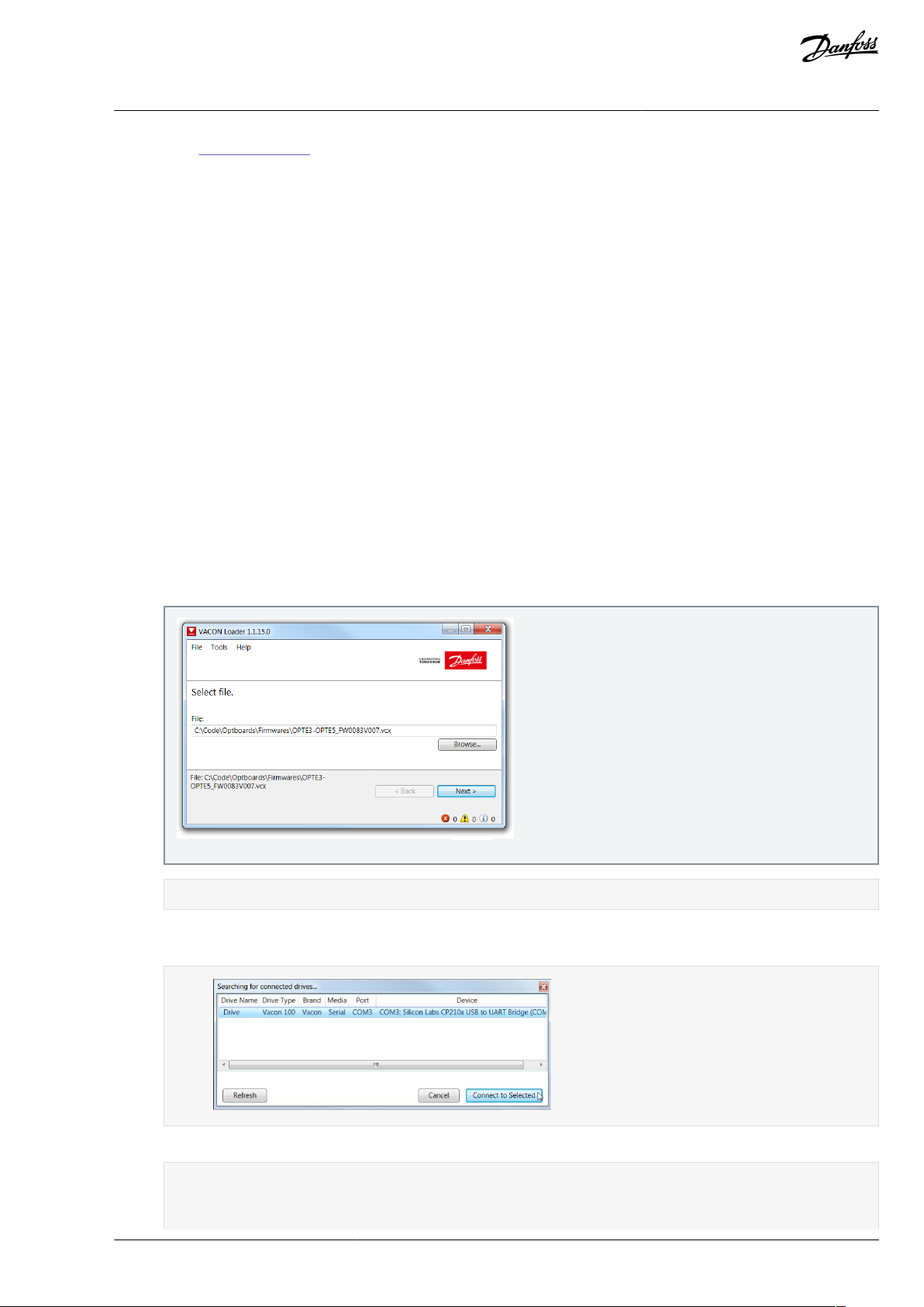
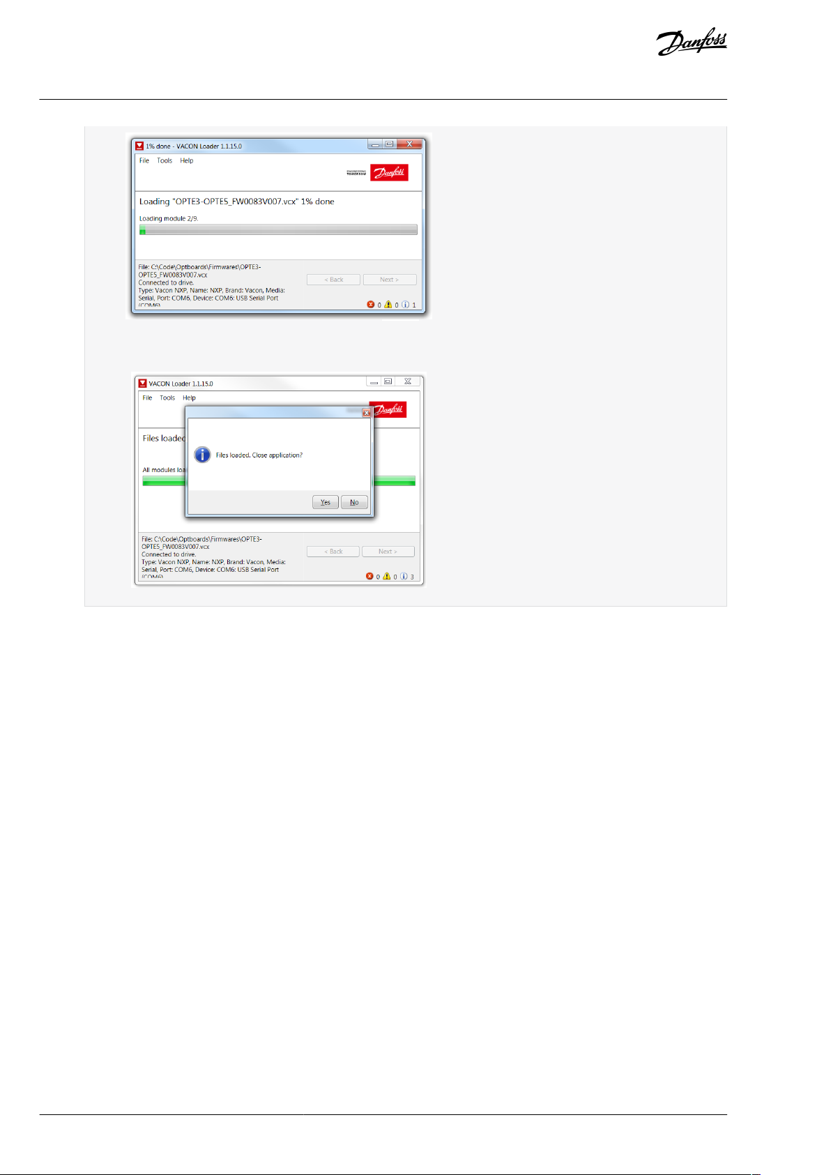
3.2.1 Updating Fieldbus Firmware with VACON® Loader
Use these instructions to upload the eldbus rmware with VACON® Loader.
NOTE! Screenshots in these instructions are examples only. The product information shown in them is dierent depending on
which option board is used.
Check the list in Before commissioning.
Adjust the baud rate if needed:
•
With VACON® 20, use the baud rate 9600.
•
With VACON® 20 X and VACON® 20 CP, the following baud rates are supported: 9600, 19200, 38400 or 57600.
•
With VACON® 100 family and VACON® NXP drives, VACON® Loader selects a correct baud rate automatically.
Procedure
1.
2.
3.
4.
Connect your PC to the controller by using the serial cable.
Open the File Explorer and select the rmware le to be updated to the option board and double-click it.
VACON® Loader software opens.
Press Next and wait for the loader to nd the network drives.
Select a drive from the list and press Connect to Selected.
5.
Select the modules to be updated, and press Next.
Firmware starts to load:
BC346130105092EN-US-000101 / DPD01583 | 35Danfoss A/S © 2020.06
Page 36
e30bh636.10
e30bh637.10
VACON® OPTEA/OPTE9 Ethernet Board
User Guide
Commissioning
Loading is nished:
3.2.2 Updating Firmware over Ethernet with VACON® Loader
Use these instructions to upload the eldbus or VACON® control rmware over Ethernet with VACON® Loader.
OPTEA and OPTE9 boards enable updating VACON® 100 control and option board rmware over Ethernet with VACON® Loader. The
option board works as gateway for the rmware update. It means that it is not possible to update the rmware of the option board
which is being used as the update gateway.
If the rmware loading fails (for example, network is lost during update), the option board remembers used Ethernet settings and
remains in state waiting for reconnection and rmware update.
Procedure
1.
Start VACON® Loader and select the rmware le to be updated.
BC346130105092EN-US-000101 / DPD0158336 | Danfoss A/S © | 2020.06
Page 37

e30bi240.10
e30bi241.10
e30bi242.10
VACON® OPTEA/OPTE9 Ethernet Board
User Guide
Commissioning
2.
Press Next. VACON® Loader starts to scan for serial connections. At this point press Cancel.
3.
From the communication settings, change connection type to Ethernet.
VACON® Loader starts to scan drives from Ethernet networks.
4.
When the drive is found, select it and press Connect to selected. From this point on, load prosess is identical with serial connection.
BC346130105092EN-US-000101 / DPD01583 | 37Danfoss A/S © 2020.06
Page 38

e30bi243.10
e30bh636.10
e30bh637.10
VACON® OPTEA/OPTE9 Ethernet Board
User Guide
Commissioning
Firmware starts to load:
Loading is nished:
5.
If the scan does not nd the device but the IP address of the drive is available, press cancel to scan dialog and enter the
correct IP address in the IP eld. Then press Next.
BC346130105092EN-US-000101 / DPD0158338 | Danfoss A/S © | 2020.06
Page 39

e30bi244.10
e30bh917.10
VACON® OPTEA/OPTE9 Ethernet Board
User Guide
Commissioning
3.2.3 Conguring with VACON® NCIPCong
Use these instructions to set the IP addresses for the option board with VACON® NCIPCong. To nd more information about the
software features, select Help --> Manual.
Check the list in 3.1 Before Commissioning.
Procedure
1.
To launch the VACON® NCIPCong, go to the Windows Start menu and select VACON® NCIPCong.
2.
Select Conguration --> Scan and wait until the devices connected to the bus display on the left side of the screen in the
tree structure.
NOTE! The VACON® NCIPCong uses broadcast messages for scanning devices. Some network switches can block the
broadcast messages. In this case, each network node must be scanned separately.
3.
Set the option board settings.
•
To change the board name, select the cell in the column Node and enter the name of the node. Notice that it changes
the name seen only in VACON® PC tools. PROFINET I/O Name Of Station value must be changed via protocol settings
or over PROFINET I/O DCP protocol.
•
To change the node IP settings, select the cell in the right column and enter the value according to the network IP
settings. The program reports conicts with a red color in table cells.
•
To change the IP Mode, click the cell and select the correct mode from the drop-down list.
BC346130105092EN-US-000101 / DPD01583 | 39Danfoss A/S © 2020.06
Page 40

e30bh918.10
e30bh919.10
e30bh920.10
VACON® OPTEA/OPTE9 Ethernet Board
User Guide
•
4.
To change the currently active protocol, select the setting from the tree structure and click OK.
Commissioning
To commit the changes, mark the checkbox and select Conguration --> Congure from the menu.
5.
To change other settings, edit the information in the tree structure.
See 6.1 Option Board Parameters for more information about the settings.
3.2.4 Setting the Drive Parameters
3.2.4.1 Setting the Drive Parameters with VACON® NCDrive
Use these instructions to set the drive parameters with VACON® NCDrive.
Also option board parameters can be congured with VACON® NCDrive (except for the PROFINET NameOfStation parameter). However, we recommend using the VACON® NCIPCong tool to congure the option board in the VACON® NXS/P AC drives.
Check the list in 3.1 Before Commissioning.
BC346130105092EN-US-000101 / DPD0158340 | Danfoss A/S © | 2020.06
Page 41

e30bh900.10
e30bh901.10
e30bh639.10
VACON® OPTEA/OPTE9 Ethernet Board
User Guide
Commissioning
Make sure that the option board IT settings are congured with VACON®NCIPCong. See instructions in 3.2.3 Conguring with VA-
CON® NCIPCong.
NOTE! The VACON® NCDrive software is recommended to be used in LAN (Local Area Network) only.
Procedure
1.
To nd drives for connections, press the Drive Select button to scan the network drives.
2.
In the Select the active drive dialog, select the drive for the connection, press the Set Active Drive button and press Close.
The IP information presented in the dialog comes from the option board, other information comes from the drive.
3.
Press the ON-LINE button.
The NCDrive connects to the drive and starts loading parameter information.
BC346130105092EN-US-000101 / DPD01583 | 41Danfoss A/S © 2020.06
Page 42

e30bh902.10
e30bh903.10
VACON® OPTEA/OPTE9 Ethernet Board
User Guide
4.
To change the option board settings, navigate to the M7 Expander boards menu, and select the slot to which OPTEA/OPTE9
is connected.
It is possible to change parameters dened in 6.1 Option Board Parameters. If the IP address, network mask, and default
gate address are changed, "IP Mode" must be changed to "Fixed IP" to activate the settings.
Commissioning
3.2.4.2 Setting the Drive Parameters with VACON® Live
Use these instructions to set the Drive Parameters with VACON® Live.
With VACON® Live, it is possible to modify OPTEA/OPTE9 Ethernet parameters and view monitor values.
Check the list in 3.1 Before Commissioning.
NOTE! VACON® 20, VACON® 20 X, and VACON® 20 Cold Plate do not support VACON® Live connection over the OPTE9 Ethernet port.
OPTEA does not support VACON® 20, VACON® 20 X, and VACON® 20 CP drives.
Procedure
1.
Open VACON® Live. When the program starts, it asks Select startup mode. Select Online.
BC346130105092EN-US-000101 / DPD0158342 | Danfoss A/S © | 2020.06
Page 43

e30bi011.10
e30bi012.10
e30bh929.10
VACON® OPTEA/OPTE9 Ethernet Board
User Guide
2.
Select the drive that the option board is connected to and press Connect to Selected.
Commissioning
The program scans your network for compatible drives, and adds them to the list.
NOTE! The rst column is the name of the drive. However, the information about IP and MAC addresses come from the
option board (if the device on the list is an option board).
NOTE! Some switches block broadcast messages. In this case, each network node must be scanned separately.
3.
Navigate to M5 I/O and Hardware menu. Check at least the IP Settings.
It is possible to change parameters dened in 6.1 Option Board Parameters. If the IP address, network mask, and default
gate address are changed, "IP Mode" must be changed to "Fixed IP" to activate the settings.
3.3 OPTCx Emulation Mode (OPTEA)
OPTEA Advanced Dual Port Ethernet board has emulation mode for OPTC-series Ethernet boards. When OPTEA is installed to NXP
drive, it has "Mode" parameter. If value "OPTCx" is selected, then OPTEA emulates behavior of old C-series Ethernet option boards
(OPTCI, OPTCP, OPTCQ) as accurately as possible.
BC346130105092EN-US-000101 / DPD01583 | 43Danfoss A/S © 2020.06
Page 44

VACON® OPTEA/OPTE9 Ethernet Board
User Guide
Commissioning
Emulation mode can be used when old installation is expanded with few new drives and when modifying PLC logic is possible. In
emulation mode, OPTEA board identies itself as, for example, OPTCP board. It allows in PLC setup, to add new OPTCP board when
the drive actually has OPTEA board, and control it with same logic as real OPTCP boards.
Also damaged OPTCP installation can be replaced with OPTEA emulating OPTCP. Later, when replacing all drives, these emulating
boards can be reused. Update the PLC programming to use OPTEA boards and change "Mode" parameter to "normal". It allows to
use all the advanced features of OPTEA board (for example: MRP, System Redundancy).
For OPTEA the "Mode" parameter has dierent content when installed to VACON® 100 or to NXP family drive. When installed to
VACON® NXP family drive and "OPTCx" mode is selected, OPTEA emulates behavior of old C-series Ethernet option boards as accurately as possible.
To use emulation mode, use OPTEA with rmware version V002 or later and VACON® NXP drive with V197 rmware or later.
Modbus in emulation mode
NX Mode:
•
Currently this mode has no eect on Modbus functionality
OPTCx Mode:
•
Modbus supports all the same coils as OPTCI board does
•
Measurement table indexes are supported
PROFINET in emulation mode
NX Mode:
•
PLC must use OPTCP GSDML.
•
Device id is OPTCP "1".
•
Vendor id is OPTCP "0x9500" instead of "0x01BA".
•
Device type text is "OPTCP".
•
Telegrams use FBSpeedReference/FBSpeedActual types instead of NSOLL_A/NIST_A.
•
Parameter channel used with Simatic PDM does not work in NX Mode.
•
In OPTCP Name Of Station can be set with VACON® NCIPCong from the "node" eld. It is not supported, but there is separate
parameter for Name Of Station in VACON® NCIPCong when using OPTEA or OPTE9 board.
•
OPTCP's Vendor PPO3, PPO4, and PPO6 telegrams are supported.
OPTCx Mode:
•
All same changes as in NX Mode.
•
FBDIN control word bits are as in OPTCP.
VACON® 100 Mode:
•
PLC must use VACON® 100 family GSDML.
•
Device ID is "1".
•
Device type text is "VACON100".
EtherNet/IP in emulation mode
NX Mode:
•
PLC must use OPTCQ EDS.
•
AC/DC Drive Object: Parameter "Drive" mode always returns the actual drive mode.
•
In "normal" mode "process drive" mode value is returned when the instance number is 25.
•
Drive identier text is "OPTCQ" instead of being based on the drive where the option board is installed (for example: "VACON
100 INDUSTRIAL").
•
Product code is "2" instead of being based on the drive where the option board is installed.
•
Revision number (major, minor) is OPTCQ 3.5.
•
Connection instance is OPTCQ "1" instead of "103" which is used by OPTEA/OPTE9 and VACON® 100 family AC drive.
•
Motor Data Object: "Rated Current" attribute returns the value in units of 10 milliamperes (1.9A => 190). In Normal mode, the
value unit is 100 milliamperes (1.9A => 19). The same conversion is expected when setting the attribute value.
•
The Motor Data Object: "Rated Frequency" attribute returns value with two decimals (50.00 Hz => 5000). In normal mode, the
value has no decimals (50.00 Hz => 50 Hz). The same conversion is expected when setting the attribute value.
®
BC346130105092EN-US-000101 / DPD0158344 | Danfoss A/S © | 2020.06
Page 45

VACON® OPTEA/OPTE9 Ethernet Board
User Guide
•
ControlFromNet bit is set to 1 when NetControl is set to 1. In normal mode, it is set only if Control Place-parameter is set to
eldbus.
•
ReferenceFromNet bit is set to 1 when NetworkReference is set to 1. In normal mode, it is set only if Reference Place-parameter
is set to eldbus.
OPTCx Mode:
•
All same changes as in NX Mode.
VACON® 100 Mode:
•
PLC must use VACON 100 EDS.
•
Drive identier text is "VACON® 100" instead of being based on the drive where the option board is installed (for example: "VACON® 100 INDUSTRIAL").
•
Product code is "100" instead of being based on the drive where the option board is installed.
•
Revision number (major, minor) is always 2.1.
Commissioning
BC346130105092EN-US-000101 / DPD01583 | 45Danfoss A/S © 2020.06
Page 46

•
•
Software or hardware
Fast/Normal Extended
Fast safe
Control Board
NXP (serial number 761 or later)
NXP (serial number 761 or later)
System Software
NXP00002V196.vcn
NXP00002V196.vcn
Applications
(1)
Multipurpose V236 or later (Normal Extended Mode)
Any
(2)
Fieldbus option rmware version
OPTE3/E5 V006 or later
OPTE3-E5_FW0083V006.vcx or later
OPTE9 V007 or later
-
OPTEA V001 or later
OPTEA V001 or later
(3)
OPTEC V003 or later
-
OPTE6 V010 or later
-
OPTE7 V006 or later
-
Advanced safety option
-
OPTBL_FW0227V001 or later
Software
Normal Extended
System Software
INDUSTRIAL FW0072V030
FLOW FW0159V022
Fieldbus option rmware version
OPTE9: V010
OPTEA: V003
VACON® OPTEA/OPTE9 Ethernet Board
Control Interface and
User Guide
Communication
4 Control Interface and Communication
4.1 Ethernet Communication Overview
The OPTEA and OPTE9 option boards support multiple communication modes to AC drive. These modes, among other features,
enable transmitting and receiving 16 process data items at 1 ms interval. These advanced communication modes are supported
when installed to VACON® NXP family drive. See 4.2 Fieldbus Option Board Communication Modes for details.
4.2 Fieldbus Option Board Communication Modes
The VACON® eldbus option boards support the following eldbus board communication modes:
•
Normal mode, for most commonly used setups (see 4.2.3 Normal Fieldbus Communication)
•
Normal extended mode, for setups that requires 16 process data items
•
Fast mode, with low latency process data (see 4.2.4 Fast Fieldbus Communication)
•
Fast safety mode with safety "black channel" (see 4.2.5 Fast Safety Fieldbus Communication)
•
Fast PROFIBUS mode. Use other modes with new installations.
NOTE! Not all boards support all modes. For details, see 4.2.1 Requirements for Communication Modes.
The fast communication modes can be enabled to get minimum communication delay between the eldbus and application.
4.2.1 Requirements for Communication Modes
Table 10: Requirements for Dierent Fieldbus Communication Modes for VACON® NXP
1
For latest information about application support for eldbus communication modes, refer to application-specic manuals.
2
If safety option is congured to use a safety eldbus, the fast safe mode is automatically enabled regardless of used application. However, the
availability of 16 process items is limited by the application in use. Also the process data application cycle is normally set to 10 ms, instead of 1 ms for
fast application.
3
Only with Advanced Safety Option
Table 11: Requirements for Normal Extended Communication Mode for VACON® 100 Family
BC346130105092EN-US-000101 / DPD0158346 | Danfoss A/S © | 2020.06
Page 47

Software
Normal Extended
OPTE7: V006
OPTE3/OPTE5: V008
VACON® OPTEA/OPTE9 Ethernet Board
Control Interface and
User Guide
Communication
4.2.2 Fieldbus Communication Mode Features and Limitations
Fast mode
•
1 ms process data interval
•
Available in VACON® NXP slots D and E
-
Possible to run both slots simultaneously
-
Have similar process data latency in both slots
•
Service data latency is also reduced
-
Running multiple service data queries at high interval can cause high CPU load in VACON® NXP AC drive.
Fast safe mode
•
1 ms process data interval
•
Includes safety "black channel"
•
Activated/deactivated automatically, not available for setting
•
Safety eldbus must be activated in safety conguration
-
Advanced safety option board must be installed into slot D
-
Safety eldbus must be activated in safety conguration
16 process data items
•
16 process data items always require support from application
•
Available in Fast, Fast safe, and Normal extended mode
•
If no support is available in the application, the process data out is always '0', while incoming process data items 9–16 are discarded
4.2.3 Normal Fieldbus Communication
The normal eldbus communication between option board and the AC drive application is shown in Illustration 16. In normal communication, both process data, and service data are transferred in succession at 5 ms interval.
Communication delay for process data can be calculated by summing all delays together:
t = t
IOdatacycle
Example: With eldbus cycle time of 4 ms and application cycle of 10 ms, the delay is:
t = 4ms + 10ms + 2 ⋅ 5 ms + 10ms = 34ms
NOTE!: This value does not include delays of the eldbus master, jitter in the process data cycle of the communication protocol or
resending due to electronic interference.
+ t
updateinterval
+ 2 ⋅ t
communicationdelay
+ t
applicationcycle
BC346130105092EN-US-000101 / DPD01583 | 47Danfoss A/S © 2020.06
Page 48

Communication cycle
Update interval
IO Data
Cyclic
x ms
Acyclic
Parameters, etc.
Low
Priority
High
Priority
Software
10ms
10ms
Update
interval
5ms
Application
task
10-50ms
Process
Data
Application
task
50-500ms
Service
Data
Option Board Drive Control Board
e30bh626.10
Low priority
IO Data
Cyclic
x ms
Acyclic
Parameters, etc.
Low
Priority
High
Priority
Software
Option Board Drive Control Board
1ms
1ms
Application
task
1-50ms
Process
Data
Application
task
50-500ms
Service
Data
Acyclic
Update
interval
Communication cycle
e30bh627.10
VACON® OPTEA/OPTE9 Ethernet Board
User Guide
Illustration 16: Normal Fieldbus Communication
Control Interface and
Communication
4.2.4 Fast Fieldbus Communication
The fast mode decreases the communication delay between the PLC and the AC drive application signicantly by using two communication channels separately for process and service data. The process data interval is set to 1 ms, while other data is sent acyclically. When the fast mode is activated, the application can be synchronized to run with the communication cycle. The Fast communication mode is shown in Illustration 17. This mode also includes the ability to transfer 16 process data items.
The communication delay for process data in fast communication mode is (when application task is synchronized with communication):
t = t
IOdatacycle
Example: With eldbus cycle time of 1 ms, an application cycle of 1 ms the delay is:
t = 1ms + 1+1ms = 3ms
NOTE: This value does not include delays of the eldbus master, jitter in the process data cycle of the communication protocol or
resending due to electronic interference.
+ t
updateinterval
+ t
applicationcycle
Illustration 17: Fast Fieldbus Communication
BC346130105092EN-US-000101 / DPD0158348 | Danfoss A/S © | 2020.06
Page 49

VACON® OPTEA/OPTE9 Ethernet Board
Control Interface and
User Guide
Communication
4.2.5 Fast Safety Fieldbus Communication
The fast safety mode uses the same communication methods as in "Fast mode" (Illustration 17), but also transfers safety "black channel" data used to the advanced safety option board.
NOTE: This mode is automatically enabled, if an advanced safety option board is connected to slot D and the safety eldbus is acti-
vated and is not available for setting. This mode is also automatically turned o when the advanced safety option board is removed.
4.2.6 Normal Extended Mode
The normal extended mode uses the same communication method as in "Fast mode", but reduces the communication cycle to 10
ms. This mode can be used in applications where 16 process data items are required but the lowest possible communication delay is
not needed. It can also be used in these applications when the increased CPU load of Fast mode to VACON® NXP drives is undesirable.
NOTE! This mode can be automatically enabled in VACON® applications supporting 16 process data items.
4.3 Drive Control with Modbus TCP/UDP
4.3.1 Modbus Communication Overview
The Modbus-VACON® interface has the following features:
Direct control of VACON® AC drive (for example, Run, Stop, Direction, Speed reference, Fault reset)
•
Access to VACON® parameters
•
VACON® status monitoring (for example, Output frequency, Output current, and Fault code)
•
4.3.2 Quick Setup for Modbus Connection
Use these instructions to set up the Modbus connection.
Procedure
In the AC drive application, select Fieldbus as the active control place (see the AC drive Operating Guide for instructions).
1.
In the Master software, set the following:
2.
a.
Set the Control Word to 0 (2001).
b.
Set the Control Word to 1 (2001).
Drive is in status RUN.
3.
In the Master software, set the Reference value to 5000 (50.00%) (2003).
Actual speed is 5000 (25.00 Hz if MinFreq is 0.00 Hz and MaxFreq is 50.00 Hz).
4.
In the Master software, set the Control Word to 0 (2001).
Drive is in status STOP.
4.3.3 Data Addresses and Modbus Memory Map
All data addresses in Modbus messages are referenced to zero. The rst occurrence of a data item is addressed as item number zero.
Examples:
The coil known as 'Coil 1' in a programmable controller is addressed as 'Coil 0000' in the data address eld of a Modbus mes-
•
sage.
Coil 127 decimal is addressed as 'Coil 007E hex' (126 decimal).
•
Holding register 40001 is addressed as register 0000 in the data address eld of the message. The function code eld already
•
species a 'holding register' operation. Therefore the '4XXXX' reference is implicit.
Holding register 40108 is addressed as register 006B hex (107 decimal).
•
Modbus Memory Map
The VACON® variables and fault codes as well as the parameters can be read and written from Modbus. The parameter addresses are
determined in the application. Every parameter and actual value has been given an ID number in the application. The ID numbering
of the parameters and the parameter ranges and steps can be found in the application manual in question. The parameter values
are given without decimals. If several parameters/actual values are read with one message, the addresses of the parameters/actual
values must be consecutive.
BC346130105092EN-US-000101 / DPD01583 | 49Danfoss A/S © 2020.06
Page 50

Function code
Current terminology
Access type
Address range (hex)
1 (0x01)
Read coils
Discrete
00000–0FFFF
2 (0x02)
Read Input Discrete
Discrete
10000–1FFFF
3 (0x03)
Read holding registers
16-bit
40000–4FFFF
4 (0x04)
Read input registers
16-bit
30000–3FFFF
5 (0x05)
Force single coils
Discrete
00000–0FFFF
6 (0x06)
Write single register
16-bit
40000–4FFFF
15 (0x0F)
Force multiple coils
Discrete
00001–0FFFF
16 (0x10)
Write multiple registers
16-bit
40000–4FFFF
23 (0x17)
Read/Write multiple registers
16-bit
40000–4FFFF
Address
Function
Purpose
0001
RUN/STOP
Control Word, bit 0
0002
Direction
Control Word, bit 1
0003
Fault reset
Control Word, bit 2
0017
Reset
Clears operation days trip counter
0018
Reset
Clears energy trip counter
Address
Function
Purpose
40101
Reset
Clears operation days trip counter
40301
Reset
Clears energy trip counter
Address
Function
Purpose
0017
Reset
Clears operation days trip counter
0018
Reset
Clears energy trip counter
VACON® OPTEA/OPTE9 Ethernet Board
User Guide
NOTE! Broadcasting is not supported in TCP.
Table 12: Supported Functions
Control Interface and
Communication
4.3.4 Coil Registers
Coil registers contain binary data (Read/Write).
Table 13: Dened Coil Registers
4.3.5 Resettable Trip Counters
The VACON® AC drives have trip counters for operation days and energy. These counters can be reset to zero.
To reset the trip counters, write value '1' to addresses dened in Table 14. Resetting the counters is not supported in VACON® 20,
VACON® 20 X, or VACON® 20 CP.
Table 14: Resettable Trip Counters
In OPTCI, to clear the resettable trip counters, write '1' to the addresses listed in Table 15.
Table 15: Resettable Trip Counters for OPTCI
BC346130105092EN-US-000101 / DPD0158350 | Danfoss A/S © | 2020.06
Page 51

Address
Function
Purpose
1
Ready
Status Word, bit 0
2
Run
Status Word, bit 1
3
Direction
Status Word, bit 2
4
Fault
Status Word, bit 3
5
Alarm
Status Word, bit 4
6
At reference
Status Word, bit 5
7
Zero speed
Status Word, bit 6
8
Flux ready
Status Word, bit 7
Address range
Purpose
Access type
Details
R/W
Max R/ W
size
1–5
Operation day counter
16-bit
See Table 25
RO
5/0
101–105
Resettable operation day counter
16-bit
See Table 27
R, Write 1 to rst index to reset
5/0
201–203
Energy counter
16-bit
See Table 29
RO
5/0
301–303
Resettable energy counter
16-bit
See Table 31
R, Write 1 to rst index to reset
5/0
401–430
Fault history
16-bit
See Table 32
RO
30/0
Address range
Purpose
Access type
Details
R/W
Max R/W size
0001–2000
VACON® Application IDs
16-bit
See Table 19
RW
30/30
2001–2019
FBProcessDataIN
16-bit
See Table 20
RW
19/19
2051–2086
FBProcessDataIN
32-bit
(1)
See Table 20
RW
36/36
2101–2119
FBProcessDataOUT
16-bit
See Table 21
RO
19/0
2151–2186
FBProcessDataOUT
32-bit
(1)
See Table 21
RO
36/0
2200–10000
VACON® Application IDs
16-bit
See Table 19
RW
30/30
10501–10530
IDMap
16-bit
See Illustration 18
RW
30/30
VACON® OPTEA/OPTE9 Ethernet Board
User Guide
4.3.6 Input Discrete Registers
Input discrete registers contain binary data (Read).
Table 16: Dened Input Discrete Registers
Control Interface and
Communication
4.3.7 Input Registers
The values can be read with function code 4. They are for compatibility with the OPTCI option board. They return the same values as
holding register counterparts.
Table 17: Input Registers
4.3.8 Holding Registers
The values can be read with function code 3. Modbus registers are mapped to drive IDs as listed in Table 18.
Table 18: Dened Holding Registers
BC346130105092EN-US-000101 / DPD01583 | 51Danfoss A/S © 2020.06
Page 52

Address range
Purpose
Access type
Details
R/W
Max R/W size
10601–10630
IDMap Read/Write
16-bit
See Table 22
RW
30/30
(2)
10701–10760
IDMap Read/Write
32-bit
(1)
See Table 22
RW
30/30
20001–40000
VACON® Application IDs
32-bit
(1)
See Table 19
RW
30/30
40001–40005
Operation day counter
16-bit
See Table 25
RO
5/0
40011–40012
Operation day counter
32-bit
(1)
See Table 24
RO
2/0
40101–40105
Resettable operation day counter
16-bit
See Table 27
R, Write 1 to rst index to reset
5/0
40111–40112
Resettable operation day counter
32-bit
See Table 26
RO
2/0
40201–40203
Energy counter
16-bit
See Table 29
RO
3/0
40211–40212
Energy counter
32-bit
See Table 28
RO
2/0
40301–40303
Resettable energy counter
16-bit
See Table 31
R, Write 1 to rst index to reset
3/0
40311–40312
Resettable energy counter
32-bit
See Table 30
RO
2/0
40400
Reset fault history
16-bit
RW
1/1
40401–40430
Fault history
16-bit
See Table 32
RO
30/0
40501
Communication timeout
16-bit
See Table 35
RW
1/1
40511–40568
Fault history with 16-bit fault codes
16-bit
See Table 33
RO
30/0
40601–40801
Fault history with time stamps
16-bit
See Table 34
RO
30/0
Address range
Purpose
ID range
0001–2000
16-bit application parameters
1–2000
2200–10000
16-bit application parameters
2200–10000
20001–40000
32-bit application parameters
1–10000
VACON® OPTEA/OPTE9 Ethernet Board
User Guide
Control Interface and
Communication
1
These items are supported only in VACON® 100 family AC drives. Not supported in current version. See
Ethernet Drive Support and 1.7.2 VACON® OPTE9 Dual Port Ethernet Drive Support.
2
In VACON® 20, VACON® 20 X / CP, the maximum R/W size for IDmap operations is 12/30.
1.7.1 VACON® OPTEA Advanced Dual Port
4.3.8.1 VACON® Application IDs
Application IDs are parameters that depend on the application of the drive. These parameters can be read and written by pointing
the corresponding memory range directly or by using the so-called ID map. The easiest way to read a single parameter value or
parameters with consecutive ID numbers is to use a straight address. It is possible to read 30 consecutive ID addresses. Notice that
the operation fails when just one of the consecutive IDs does not exist.
Parameters which have 32-bit value can be read from their own range. For example, to read the value for ID 864 (FB Status Word),
the address must be set to 21726. This address value comes from values: 20000 + ((ID -1) * 2). The ID value is reduced with one
because of zero-based addressing and the result is multiplied by 2 because one 32bit value takes two (16-bit) addresses.
Table 19: Parameter IDs
4.3.8.2 FB Process Data In
The process data elds are used to control the AC drive (for example, Run, Stop, Reference, Fault Reset) and quickly to read actual
values (for example, Output frequency, Output current, Fault code). The values in these indexes can be read and written. The structure of the elds is described in
Table 20.
BC346130105092EN-US-000101 / DPD0158352 | Danfoss A/S © | 2020.06
Page 53

16-bit address
32-bit address
Name
Range/Type
2001
2051 = High data
2052 = Low data
FB Control Word
Binary coded
2002–FB General Control Word
Binary coded
2003
2053 = High data
2054 = Low data
FB Speed Reference
0…10000 (100%)
2004
2055 = High data
2056 = Low data
FB Process Data In 1
see 4.7 VACON® Process Data Description
2005
2057 = High data
2058 = Low data
FB Process Data In 2
2006
2059 = High data
2060 = Low data
FB Process Data In 3
2007
2061 = High data
2062 = Low data
FB Process Data In 4
2008
2063 = High data
2064 = Low data
FB Process Data In 5
2009
2065 = High data
2066 = Low data
FB Process Data In 6
2010
2067 = High data
2068 = Low data
FB Process Data In 7
2011
2069 = High data
2070 = Low data
FB Process Data In 8
2012
2071 = High data
2072 = Low data
FB Process Data In 9
see 4.7 VACON® Process Data Description
2013
2073 = High data
2074 = Low data
FB Process Data In 10
2014
2075 = High data
2076 = Low data
FB Process Data In 11
2015
2077 = High data
2078 = Low data
FB Process Data In 12
2016
2079 = High data
2080 = Low data
FB Process Data In 13
2017
2081 = High data
2082 = Low data
FB Process Data In 14
2018
2083 = High data
FB Process Data In 15
VACON® OPTEA/OPTE9 Ethernet Board
User Guide
Table 20: FB Process Data In
Control Interface and
Communication
BC346130105092EN-US-000101 / DPD01583 | 53Danfoss A/S © 2020.06
Page 54

16-bit address
32-bit address
Name
Range/Type
2084 = Low data
2019
2085 = High data
2086 = Low data
FB Process Data In 16
16-bit address
32-bit address
Name
Range/Type
2101
2151 = High data
2152 = Low data
FB Status Word
Binary coded
2102
–
With 16-bit, FB General Status Word (High data)
Binary coded
2103
2153 = High data
2154 = Low data
FB Actual Speed
0…10000 (100.00%)
2104
2155 = High data
2156 = Low data
FB Process Data Out 1
See 4.7 VACON® Process Data Description
2105
2157 = High data
2158 = Low data
FB Process Data Out 2
2106
159 = High data
2160 = Low data
FB Process Data Out 3
2107
2161 = High data
2162 = Low data
FB Process Data Out 4
2108
2163 = High data
2164 = Low data
FB Process Data Out 5
2109
2165 = High data
2166 = Low data
FB Process Data Out 6
2110
2167 = High data
2168 = Low data
FB Process Data Out 7
2111
2169 = High data
2170 = Low data
FB Process Data Out 8
2112
2171 = High data
2172 = Low data
FB Process Data Out 9
See 4.7 VACON® Process Data Description
VACON® OPTEA/OPTE9 Ethernet Board
Control Interface and
User Guide
Control word bits
See 4.7 VACON® Process Data Description for control word bit descriptions.
Control Word Monitoring Values
Drive Control Word and Protocol Control Word monitoring values always shows the same value when using Modbus. It is the same
value as received from network. The only exception to this is that when using the VACON® NXP AC drives, the bit 15 of the Control
word is changed to indicate the "Master connection status". The bit 15 is set to 1 when master device has written process data and
the bit is cleared when the connection is closed/lost.
Communication
4.3.8.3 FB Process Data Out
Values in these indexes can be only read, not written.
Table 21: Fieldbus Process Data OUT
BC346130105092EN-US-000101 / DPD0158354 | Danfoss A/S © | 2020.06
Page 55

16-bit address
32-bit address
Name
Range/Type
2113
2173 = High data
2174 = Low data
FB Process Data Out 10
2114
2175 = High data
2176 = Low data
FB Process Data Out 11
2115
2177 = High data
2178 = Low data
FB Process Data Out 12
2116
2179 = High data
2180 = Low data
FB Process Data Out 13
2117
2181 = High data
2182 = Low data
FB Process Data Out 14
2118
2183 = High data
2184 = Low data
FB Process Data Out 15
2119
2185 = High data
2186 = Low data
FB Process Data Out 16
VACON® OPTEA/OPTE9 Ethernet Board
User Guide
Control Interface and
Communication
Status Word bits
See 4.7 VACON® Process Data Description for status word bit descriptions. The use of process data depends on the application. In a
typical situation, the device is started and stopped with the Control Word (CW) written by the Master and the Rotating speed is set
with Reference (REF). With PD1…PD16, the device can be given other reference values (for example, Torque reference). With the
Status Word (SW) read by the Master, the status of the device can be seen. Actual Value (ACT) and PD1…PD16 show the other actual
values.
Status Word Monitoring Values
The Drive Status Word and Protocol Status Word monitoring values always shows the same value when using Modbus. It is the same
value than what is sent to the network.
4.3.8.4 ID Map
The ID map makes it possible to read consecutive memory blocks that contain parameters whose IDs are not in a consecutive order.
The address range 10501–10530 is called 'IDMap', and it includes an address map in which it is possible to write the parameter IDs in
any order. The address range 10601–10630 is called 'IDMap Read/Write', and it includes values for parameters written in the IDMap.
When one ID number has been written in the map cell 10501, the corresponding parameter value can be read and written in the
address 10601, and so on. The address range 10701–10760 contains the ID Map for 32-bit values. Maximum of 30 IDs and ID values
can be written and read with single request. In VACON® 20 and 20 X/CP it is possible to access only 12 ID value items at a time.
NOTE! 32-bit data not supported in the current version. See 1.7.1 VACON® OPTEA Advanced Dual Port Ethernet Drive Support and
1.7.2 VACON® OPTE9 Dual Port Ethernet Drive Support.
BC346130105092EN-US-000101 / DPD01583 | 55Danfoss A/S © 2020.06
Page 56

ID Value
699 123
700 321
701 456
702 654
703 1789
704
987
705
2741
706
1147
707 258
708 3852
Parameters
Address Data: ID
10501 700
10502 702
10503 707
10504 704
Address Data: ID
10601 321
10602 654
10603 258
10604 987
ID Map
e30bh905.10
Address
Data
10601
Data included in parameter ID700
10602
Data included in parameter ID702
10603
Data included in parameter ID707
10604
Data included in parameter ID704
Address
Data
10701
Data High, parameter ID700
10702
Data Low, parameter ID700
10703
Data High, parameter ID702
10704
Data Low, parameter ID702
Address
Description
40011 High data
40012 Low data
The counter in registers 40011d to 40012d holds the value of operation days as seconds in a 32-bit unsigned
integer.
VACON® OPTEA/OPTE9 Ethernet Board
Control Interface and
User Guide
Illustration 18: ID Map Initialization Example
Once the ID Map address range has been initialized with the parameter IDs, the parameter values can be read and written in the
IDMap Read/Write address range address (IDMap address + 100).
Communication
Table 22: Parameter Values in 16-bit IDMap Read/Write Registers
If the ID Map table has not been initialized, all the elds show index as '0'. If it has been initialized, the parameter IDs included in it
are stored in the ash memory of the option board.
Table 23: Example of Parameter Values in 32-bit IDMap Read/Write Registers
4.3.8.5 Operation Day Counter
Control unit operating time counter (total value). This counter cannot be reset. The values are read only.
NOTE! The feature Operation day counter does not work with VACON® 20, VACON® 20 X, or VACON® 20 CP AC drives.
Table 24: Operation Day Counter as Seconds
The operation day counter in registers 40001d to 40005d holds the value of operation days counter. The values are read only.
BC346130105092EN-US-000101 / DPD0158356 | Danfoss A/S © | 2020.06
Page 57

Holding register address
Input register address
Purpose
40001
1
Years
40002
2
Days
40003
3
Hours
40004
4
Minutes
40005
5
Seconds
Address
Description
40111 High data
40112 Low data
This counter in registers 40111d to 40112d holds the value of resettable operation days as seconds in a 32-bit
unsigned integer.
Holding register address
Input register address
Purpose
40101
101
Years
40102
102
Days
40103
103
Hours
40104
104
Minutes
40105
105
Seconds
Address
Description
40211 High data
40212 Low data
The counter is in registers 40211d to 40212d. It is a 32-bit oating point (IEEE 754) value containing the number of kilowatt-hours (kWh) that is in the energy counter of the drive. This value is read-only.
VACON® OPTEA/OPTE9 Ethernet Board
Control Interface and
User Guide
For compatibility with VACON® 100 family internal Modbus TCP/UDP and the OPTCI option board, this counter is found from two
dierent register areas: holding registers 40001d to 40005d and input registers 1d to 5d.
Table 25: Operation Day Counter
Communication
4.3.8.6 Resettable Operation Day Counter
This register holds the value for resettable control unit operating time counter (trip value). The values are read only.
For resetting this counter, see 4.3.5 Resettable Trip Counters.
NOTE! The feature Resettable operation day counter does not work with VACON® 20, VACON® 20 X, or VACON® 20 CP AC drives.
Table 26: Resettable Operation Days Counter as Seconds
The resettable operation day counter in registers 40101d to 40105d holds the value of operation days counter. For compatibility
with VACON® 100 family internal Modbus TCP/UDP and the OPTCI option board, this counter is found from two dierent register
areas: holding registers 40101d to 40105d and input registers 30101d to 30105d.
Table 27: Resettable Operation Day Counter
4.3.8.7 Energy Counter
This counter holds the value of total amount of energy taken from a supply network. This counter cannot be reset. The values are
read only.
Table 28: Energy Counter as kWh
These registers hold three values for the energy counter, amount of energy used, format of the energy value and unit of the energy
value.
For compatibility with VACON® 100 family internal Modbus TCP/UDP and the OPTCI option board, this counter is found from two
dierent register areas: holding registers 40201d to 40203d and input registers 201d to 203d.
BC346130105092EN-US-000101 / DPD01583 | 57Danfoss A/S © 2020.06
Page 58

Holding register address
Input register
address
Purpose
Description
40201
201
Energy
Amount of energy taken from a supply network.
40202
202
Format
The last number of the Format eld indicates the decimal point place in the Energy
eld.
Example:
40 = 4 number of digits, 0 fractional digits
41 = 4 number of digits, 1 fractional digit
42 = 4 number of digits, 2 fractional digits
40203
203
Unit
1 =kWh
2 =MWh
3 =GWh
4 =TWh
Unit of the value.
Address
Description
40311 High data
40312 Low data
The counter is in registers 40311d to 40312d. It is a 32-bit oating point (IEEE 754) value containing the number of kilowatt-hours (kWh) from the resettable energy counter of the drive.
Holding register address
Input register
address
Purpose
Description
40301
301
Energy
Amount of energy taken from a supply network.
40302
302
Format
The last number of the Format eld indicates the decimal point place in the Energy
eld.
Example:
40 = 4 number of digits, 0 fractional digits
41 = 4 number of digits, 1 fractional digit
42 = 4 number of digits, 2 fractional digits
40303
303
Unit
1 =kWh
2 =MWh
3 =GWh
Unit of the value.
VACON® OPTEA/OPTE9 Ethernet Board
User Guide
Example: If energy = 1200, format = 52, unit = 1, then actual energy is 12.00 kWh.
Table 29: Energy Counter
Control Interface and
Communication
4.3.8.8 Resettable Energy Counter
This counter holds the value of total amount of energy taken from a supply network since the counter was last reset. For resetting
this counter, see 4.3.5 Resettable Trip Counters. The values are read only.
Table 30: Resettable Energy Counter as kWh
These registers hold three values for the energy counter, amount of energy used, format of the energy value and unit of the energy
value.
For compatibility with VACON® 100 family internal Modbus TCP/UDP and the OPTCI option board, this counter is found from two
dierent register areas: 40301d to 40303d and 301d to 303d.
Example: If energy = 1200, format = 52, unit = 1, then actual energy is 12.00 kWh.
Table 31: Resettable Energy Counter
BC346130105092EN-US-000101 / DPD0158358 | Danfoss A/S © | 2020.06
Page 59

Holding register address
Input register
address
Purpose
Description
4 =TWh
Holding register address
Input register address
Purpose
40401
401
Upper byte is a fault code, lower byte is a subcode
40402
402-40403
403-...
...-40429
429
-
Holding register address
Purpose
Description
40511
Fault code 1
16-bit fault code in index 1.
40512
Subcode 1
16-bit subcode for the fault in index 1.
40513
Fault code 2
16-bit fault code in index 2.
40514
Subcode 2
16-bit subcode for the fault in index 2.
...
...-40567
Fault code 29
-
40568
Subcode 29
-
VACON® OPTEA/OPTE9 Ethernet Board
Control Interface and
User Guide
Communication
4.3.8.9 Fault History
The fault history is readable from address 40401 onward. The faults are listed in chronological order so that the latest fault is mentioned rst and the oldest last. The fault history can contain 29 faults at the same time. (In VACON® 20, VACON® 20 X, and VACON
20 CP it is possible to read 9 faults). For compatibility with VACON® 100 family internal Modbus TCP/UDP and the OPTCI option
board, this counter is also found from input register area: 401d to 403d.
NOTE! Reading the fault history items is slow. Reading all 30 items at once can take up to 3 s depending on drive type and rmware
versions.
The fault history contents are shown in Table 32.
Table 32: Fault History
®
4.3.8.10 Fault History with 16-bit Error Codes
The fault history is readable from address 40511 onward. The faults are listed in a chronological order so that the latest fault is mentioned rst and the oldest last. These addresses contain the fault code and the subcode for the fault. Reading can be started from
any address. (In VACON® 20, VACON® 20 X, and VACON® 20 CP it is possible to read 9 faults).
NOTE! Reading the fault history items is slow. Reading all 30 items at once can take up to 3 s depending on drive type and rmware
versions.
Table 33: Fault History with 16-bit Error Codes
4.3.8.11 Reset Fault History
Drive fault history can be reset by writing "1" to address 40400. Value in this address can be read but it is always zero. Notice that
fault history cannot be reset when there is an active fault.
4.3.8.12 Reset Fault with Time Stamps
The fault history with time stamps is readable from address 40601 onward. The faults are listed in a chronological order so that the
latest fault is mentioned rst and the oldest last. These addresses contain fault code, subcode, and time stamp for the fault. Reading
BC346130105092EN-US-000101 / DPD01583 | 59Danfoss A/S © 2020.06
Page 60

Holding register address
Purpose
Description
40601
Fault Code 1
16-bit fault code in index 1
40602
Subcode 1
16-bit fault subcode in index 1
40603
Time stamp HI 1
32-bit time stamp in seconds high byte in index 1
40604
Time stamp LO 1
32-bit time stamp in seconds low byte in index 1
40605
Time stamp ms 1
Time stamp milliseconds in index 1
40606
Fault Code 2
16-bit fault code in index 2
...
...
...
40801
Time stamp ms 40
Time stamp milliseconds in index 40
Holding register address
Purpose
Description
40501
Communication timeout
Connection timeout value for this connection in seconds.
VACON® OPTEA/OPTE9 Ethernet Board
Control Interface and
User Guide
can be started from any address. (In VACON® 20, VACON® 20X, and VACON® 20CP it is possible to read 9 faults. In VACON® NXP
family AC drives it is possible to read 30 faults).
NOTE! Only 25 items can be read with single request. Reading the fault history items is slow. Reading 25 items at once can take up to
3 s depending on drive type and rmware versions.
Table 34: Fault History with Time Stamps
Communication
4.3.9 Connection Timeout in Modbus Communication
It is possible to open up to three connections to the option board. One of the connections could be used for process data and other
just for reading monitoring data. Usually it is desirable that if "monitor" connection gets disconnected, no fault is generated. However when the connection is handling the process data, a fault must be generated in the time specied.
This register address enables custom communication timeout for each connection. If a custom timeout value is used, it must be
given every time a connection is opened. Timeout can be set only to the connection used to access this register. By default the
connection uses the communication timeout value given via panel parameters.
If the cable is disconnected, a eldbus fault is activated after the timeout period. When communication timeout is zero, no fault is
activated.
Table 35: Communication Timeout Register
BC346130105092EN-US-000101 / DPD0158360 | Danfoss A/S © | 2020.06
Page 61

Communicating
Received packet during
communication
timeout time?
Timeout
CheckYes
Yes
Closed
Yes
No
No
No
Broken
Communication timeout zero?
Connection closed or broken?
FAULT! No fault
Has second connection with communication timeout
other than zero?
e30bh892.10
ADDRESS
01 hex
Slave address 1 hex (= 1)
FUNCTION
10 hex
Function 10 hex (= 16)
DATA
Starting address HI
07 hex
Starting address 07D0 hex (= 2000)
Starting address LO
D0 hex
Number of registers HI
00 hex
Number of registers 0003 hex (= 3)
Number of registers LO
03 hex
Byte count
06 hex
Byte count 06 hex (= 6)
Data HI
00 hex
Data 1 = 0001 hex (= 1). Setting control word run bit to 1.
Data LO
01 hex
Data HI
00 hex
Data 2 = 0000 hex (= 0).
Data LO
00 hex
Data HI
13 hex
Data3 = 1388 hex (= 5000), Speed Reference to 50.00%
Data LO
88 hex
ERROR CHECK
CRC HI
C8 hex
CRC eld C8CB hex (= 51403)
CRC LO
CB hex
VACON® OPTEA/OPTE9 Ethernet Board
User Guide
Control Interface and
Communication
Illustration 19: The Connection Timeout in Modbus TCP/UDP
4.3.10 Example Messages
4.3.10.1 Write Process Data
Write the process data 42001…42003 with command 16 (Preset Multiple Registers).
Table 36: Command Master–Slave
BC346130105092EN-US-000101 / DPD01583 | 61Danfoss A/S © 2020.06
Page 62

011007D0000306000100001388C8CB
ADDRESS
01 hex
Slave address 1 hex (= 1)
FUNCTION
10 hex
Function 10 hex (= 16)
DATA
Starting address HI
07 hex
Starting address 07D0 hex (= 2000)
Starting address LO
D0 hex
Number of registers HI
00 hex
Number of registers 0003 hex (= 3)
Number of registers LO
03 hex
ERROR CHECK
CRC HI
80 hex
CRC 8085 hex (= 32901)
CRC LO
85 hex
011007D0000380
85
ADDRESS
01 hex
Slave address 1 hex (= 1)
FUNCTION
10 hex
Function 4 hex (= 4)
DATA
Starting address HI
08 hex
Starting address 0836 hex (= 2102)
Starting address LO
36 hex
Number of registers HI
00 hex
Number of registers 0002 hex (= 2)
Number of registers LO
02 hex
ERROR CHECK
CRC HI
C8 hex
CRC 93A5 hex (= 37797)
CRC LO
CB hex
01040836000293
A5
ADDRESS
01 hex
Slave address 1 hex (= 1)
FUNCTION
04 hex
Function 4 hex (= 4)
DATA
Byte count
04 hex
Byte count 4 hex (= 4)
Data HI
13 hex
Speed reference = 1388 hex (=5000 => 50.00%)
Data LO
88 hex
VACON® OPTEA/OPTE9 Ethernet Board
User Guide
Table 37: Message Frame
The reply to the message of Preset Multiple Register is the echo of 6 rst bytes.
Table 38: Answer Slave - Master
Control Interface and
Communication
Table 39: Reply Frame
4.3.10.2 Read Process Data
Read the Process Data 42103…42104 with command 4 (Read Input Registers).
Table 40: Command Master–Slave
Table 41: Message Frame
The reply to the Read Input Registers message contains the values of the read registers.
Table 42: Answer Slave–Master
BC346130105092EN-US-000101 / DPD0158362 | Danfoss A/S © | 2020.06
Page 63

Data HI
09 hex
Output Frequency = 09C4 hex (=2500 =>25.00 Hz)
Data LO
C4 hex
ERROR CHECK
CRC HI
78 hex
CRC 78E9 hex (= 30953)
CRC LO
E9 hex
010404138809C478E9
ADDRESS
01 hex
Slave address 1 hex (= 1)
FUNCTION
04 hex
Function 4 hex (= 4)
DATA
Starting address HI
17 hex
Starting address 1770 hex (= 6000)
Starting address LO
70 hex
Number of registers HI
00 hex
Invalid number of registers 0005 hex (= 5)
Number of registers LO
05 hex
ERROR CHECK
CRC HI
34 hex
CRC 3466 hex (= 13414)
CRC LO
66 hex
01041770000534
55
ADDRESS
01 hex
Slave address 1 hex (= 1)
FUNCTION
84 hex
Most signicant bit set to 1
DATA
Error code
04 hex
Error code 04 => Slave device failure
ERROR CHECK
CRC HI
42 hex
CRC 42C3 hex (= 17091)
CRC LO
C3 hex
01840442C3
VACON® OPTEA/OPTE9 Ethernet Board
Control Interface and
User Guide
Table 43: Reply Frame
Communication
4.3.10.3 Exception Response
In an exception response, the Slave sets the most-signicant bit (MSB) of the function code to 1. The Slave returns an exception code
in the data eld.
Table 44: Command Master–Slave
Table 45: Message Frame
Exception response
Table 46: Answer Slave–Master
Table 47: Reply Frame
4.4 Drive Control with PROFINET
4.4.1 PROFINET Communication Overview
The PROFIdrive prole species telegrams used for process communication. The option boards support four types of dierent telegrams with and without extra process data items. These telegrams contain either PROFIdrive or VACON® specic signals or a combination of both.
BC346130105092EN-US-000101 / DPD01583 | 63Danfoss A/S © 2020.06
Page 64

VACON® OPTEA/OPTE9 Ethernet Board
Control Interface and
User Guide
It is also possible to use up to eight (8) Process Data elds, or sixteen (16) when using extended or fast communication mode. If the
normal communication mode is used, the upper 8 Process Data items (9–16) are either zeroes (actual data) or not used (setpoint
data). See 4.1 Ethernet Communication Overview for more details. For descriptions of dierent types of telegrams and the signals
that form them, see 4.4.5 Telegram Types.
Communication
4.4.2 Quick Setup for PROFINET Connection
Use these instructions to set up the PROFINET connection.
In the instruction, telegram ST1 with STW1/ZSW1 and NSOLL_A/NIST_A is used as example.
Procedure
1.
In the AC drive application, select Fieldbus as the active control place (see the AC drive Operating Guide for instructions).
2.
In the Master software, set the following:
a.
Set the Control Word value to 0 hex.
b.
Set the Control Word value to 47E hex.
c.
Set the Control Word value to 47F hex.
Drive is in status RUN.
3.
In the Master software, set the Reference value to 2000 Hex (=50.00%).
Actual speed is 5000 (25.00 Hz if MinFreq is 0.00 Hz and MaxFreq is 50.00 Hz).
4.
In the Master software, set the Control Word value to 47E hex.
Drive is in status STOP.
4.4.3 PROFIdrive 4.1 Prole Overview
To provide interoperability between devices from dierent manufacturers, a "standard" must be dened so that:
•
The devices behave in the same way.
•
The devices produce and/or consume the same basic set of I/O data.
•
The devices contain the same basic set of congurable attributes.
The formal denition of this information is known as a device prole. Some AC drives support only some of the functionalities. See
4.7 VACON® Process Data Description.
4.4.4 PROFIdrive 4.1 State Machine
STW1 (Control Word) and ZSW1 (Status Word) follow the state machine described in Illustration 20.
BC346130105092EN-US-000101 / DPD0158364 | Danfoss A/S © | 2020.06
Page 65

Highest priority transition
..
..
Lowest priority transition
15
11
13
12
9
8
14
1
6
10
4
7
3
5
2
0
Power ON
S1: Switching On Inhibited
ZSW1 bit 6 = True; 0,1,2 = False
General state diagram
Power on
S2: Ready For Switching On
ZSW1 bit 0 = True; 1,2,6 = False
Ramp stop
Quick stop
S5: Switching Off
ZSW1 bit0,1 =True
bit 2,6=False
S3: Switched On
ZSW1 bit 0,1 = True; 2,6 = False
S4: Operation
ZSW1 bit 0,1,2 = True; 6=False
e30bh623.10
#
Bits of control word
Value
(hex)
Action in VACON® 100
family & VACON
®
20X/CP
Action in VACON® 20
Action in VACON
®
NXP
(1)
0--
Self-initiation is performed
1
OFF AND No Coast Stop AND
No Quick Stop STW1 bit 0 =
False; 1, 2 = True
0x47E
None, requires that Drive is READY (ZSW1 status word bit 13)
2
Coast Stop OR Quick Stop
STW1 bit 1 = False OR bit 2 =
False
-
None
3
ON
STW1 bit 0 = True
0x477
None
4
Coast Stop OR Quick Stop
-
None
5
STW1 bit 1 = False OR bit 2 =
False
-
None
6
Enable operation
STW1 bit 3 = True
0x47F
Drive function is enabled, requires that Drive is in eldbus control (ZSW1
status word bit 9)
7
Coast stop
0x47D
Stop by coast
Stop function
VACON® OPTEA/OPTE9 Ethernet Board
User Guide
Control Interface and
Communication
Illustration 20: General State Diagram
Table 48: PROFIdrive State Machine Commands
BC346130105092EN-US-000101 / DPD01583 | 65Danfoss A/S © 2020.06
Page 66

#
Bits of control word
Value
(hex)
Action in VACON® 100
family & VACON
®
20X/CP
Action in VACON® 20
Action in VACON
®
NXP
(1)
STW1 bit 1 = False
8, 12
Quick stop
STW1 bit 2 = False
0x47B
Quick stop
(2)
Stop by ramp
Stop function
9
Ramp stop
STW1 bit 0 = False
0x47E
Stop by ramp
Stop function
10
Disable operation STW1 bit 3
= False
0x477
Drive function is disabled, stop by stop function
11
Coast stop
STW1 bit 1 = False
0x47D
Stop by coast
Stop function
13, 15
Standstill detected OR Disable
operation STW1 bit 3 = False
0x477
Drive function is disabled, stop by stop function
14
ON (Re-enable operation)
0x47F
Drive function is re-enabled
Value in Standard Telegram 1
Value in VACON®specic Telegram 1
Value in VACON®-specic Telegram 2
Value in VACON®specic Telegram
3
Value in VACON®-specic Telegram 4
Drive CW
FBFixedControlWord
FBFixedControlWord
FBFixedControlWord
FBFixedControlWord
FBFixedControlWord
Drive SW
FBFixedStatusWord
FBFixedStatusWord
FBFixedStatusWord
FBFixedStatusWord
FBFixedStatusWord
Protocol
CW
STW1
FBFixedControlWord
FBGeneralControlWord
STW1
FBFixedControlWord
VACON® OPTEA/OPTE9 Ethernet Board
User Guide
Control Interface and
Communication
1
When using VACON® NXP series AC drives and option board in "PROFIdrive" mode, the stop command always follows congured stop mode and
not the stop command given from eldbus.
2
Quick stop only occurs if the application supports it. If the application does not support quick stop, a normal ramp stop is executed.
4.4.5 Telegram Types
For a list of dierent telegram types and their description, see the following:
•
4.4.5.1 Standard Telegram 1 and Variants
•
4.4.5.2 VACON®-specic Telegram 1 and Variants
•
4.4.5.3 VACON®-specic Telegram 2 and Variants
•
4.4.5.4 VACON®-specic Telegram 3 and Variants
•
4.4.5.5 VACON®-specic Telegram 4 and Variants
•
4.4.5.7 VACON®-specic Telegram Vendor PPO and Variants
Consider the following issues when selecting the telegram type:
•
Combination of devices in the network (multiple manufactureres/only VACON® devices.
•
How the motor speed is controlled.
•
Number of process data items needed.
When selecting a telegram for PROFINET communication, consider if PROFIdrive control/status word (STW1/ZSW1) is needed or if
VACON® control/status word can be used. See comparison of used Control and Status Word monitoring values in Table 49.
Table 49: Comparison of Control and Status Word Monitoring Values in Dierent Telegram Types
BC346130105092EN-US-000101 / DPD0158366 | Danfoss A/S © | 2020.06
Page 67

Value in Standard Telegram 1
Value in VACON®specic Telegram 1
Value in VACON®-specic Telegram 2
Value in VACON®specic Telegram
3
Value in VACON®-specic Telegram 4
Protocol
SW
STW1
FBFixedStatusWord
FBGeneralStatusWord
STW1
FBGeneralStatusWord
Telegram number
Telegram
Abbreviation
1
Standard Telegram 1
ST1
102
Standard Telegram 1 + 1 Process Data
ST1 + 1 PD
103
Standard Telegram 1 + 2 Process Data
ST1 + 2 PD
104
Standard Telegram 1 + 3 Process Data
ST1 + 3 PD
100
Standard Telegram 1 + 4 Process Data
ST1 + 4 PD
105
Standard Telegram 1 + 5 Process Data
ST1 + 5 PD
106
Standard Telegram 1 + 6 Process Data
ST1 + 6 PD
107
Standard Telegram 1 + 7 Process Data
ST1 + 7 PD
101
Standard Telegram 1 + 8 Process Data
ST1 + 8 PD
138
Standard Telegram 1 + 12 Process Data
(1)
ST1 + 12 PD
VACON® OPTEA/OPTE9 Ethernet Board
Control Interface and
User Guide
If the network has devices from multiple manufactures which all can be controlled with PROFIdrive control word, we recommend
using telegram type with status word STW1. It makes writing the PLC application easier, especially when the PLC has PROFIdrive
block available.
If the network consists of only VACON® devices controlled by PLC over PROFINET, it is better to use VACON® control/status word.
State machine for VACON® control/status word is simpler than in the PROFIdrive and therefore controlling the drive is also easier in
the PLC application.
Telegram selection also aects the motor speed control. With VACON® control word, the motor direction can be controlled with a
single bit. PROFIdrive motor direction is controlled with negative/ positive values. Telegrams with PROFIdrive control/status word
generally have also PROFIdrive speed reference/actual (NIST_A/NSOLL_A). Other telegrams have VACON® speed reference/actual
(FBSpeedReference/FBSpeedActual). The main dierence between these types is the integer value which means maximum allowed
motor speed (100%). In VACON® FBSpeedReference, the value is between 0d–10000d (100.00%) and in PROFIdrive NIST_A the value
is between -16384d–16384d.
NOTE! When using NSOLL_A, our minimum and maximum frequency parameters aect the speed reference dierently than when
using the FBSpeedReference directly. With NSOLL_A, the PROFINET gives zero reference to the application until NSOLL_A exceeds
the minimum reference. With FBSpeedReference, the given value is always scaled between the minimum and maximum frequency.
For example, if the Minimum Frequency is 30 Hz and the Maximum Frequency is 50 Hz, the NSOLL_A value between 0 and 9830
runs 30 Hz. With FBSpeedReference, the example value 1000 (10%) runs 32 Hz.
Dierent telegrams contain dierent number of process data items. The number of items vary from none to 16 items. Process data
can be 16 or 32 bits in size. Process data in VACON® NXP drives is only 16-bit, so telegrams which use 32-bit process data have the
upper 16 bits always as zero.
When using more than 8 process data items, the eldbus option board communication mode must be 'Fast mode with safety "black
channel"', 'Fast Mode' or 'Normal Extended' mode. See 4.2 Fieldbus Option Board Communication Modes for more information on
the communication mode.
Communication
4.4.5.1 Standard Telegram 1 and Variants
Standard Telegram 1 types are used when a standard VACON® application is used and PROFIdrive functionality is required. Telegrams listed in Table 50 use PROFIdrive-dened control word, status word, speed setpoint value, and speed actual value. When us-
ing these telegrams, the process data elds are communicated as 16-bit values.
STW1 forces edge sensitive run control.
NOTE! When a board is connected to VACON® 100 family AC drive and its mode parameter is set to “NX Mode”, the option board
uses FBSpeedReference/FBSpeedActual instead of NSOLL_A/ NIST_A as backward compatibility for OPTCP option board.
Table 50: Standard Telegram 1 and Variants
BC346130105092EN-US-000101 / DPD01583 | 67Danfoss A/S © 2020.06
Page 68

Telegram number
Telegram
Abbreviation
139
Standard Telegram 1 + 16 Process Data
(1)
ST1 + 16 PD
Bytes
Setpoint
Actual value
1...2
STW1
4.4.6.1 PROFIdrive 4.1 Control Word (STW1)
ZSW1
4.4.6.2 PROFIdrive 4.1 Status Word (ZSW1)
3...4
NSOLL_A
4.4.6.3 Setpoint Value
NIST_A
4.4.6.4 Actual Speed Value
5...6
PDI1
4.7.5 Process Data
PDO1
4.7.5 Process Data
7...8
PDI2
PDO2
...
...
...
19...20
PDI8
PDO8
21...22
PDI9
(1)
PDO9
(1)
...
...
...
35...36
PDI16
(1)
PDO16
(1)
Telegram number
Telegram
Abbreviation
108
Vendor Telegram 1
Vendor 1
109
Vendor Telegram 1 + 1 Process Data
Vendor 1 + 1 PD
110
Vendor Telegram 1 + 2 Process Data
Vendor 1 + 2 PD
111
Vendor Telegram 1 + 3 Process Data
Vendor 1 + 3 PD
112
Vendor Telegram 1 + 4 Process Data
Vendor 1 + 4 PD
113
Vendor Telegram 1 + 5 Process Data
Vendor 1 + 5 PD
114
Vendor Telegram 1 + 6 Process Data
Vendor 1 + 6 PD
115
Vendor Telegram 1 + 7 Process Data
Vendor 1 + 7 PD
116
Vendor Telegram 1 + 8 Process Data
Vendor 1 + 8 PD
140
Vendor Telegram 1 + 12 Process Data
(1)
Vendor 1 + 12 PD
141
Vendor Telegram 1 + 16 Process Data
(1)
Vendor 1 + 16 PD
VACON® OPTEA/OPTE9 Ethernet Board
User Guide
1
12 and 16 process data items are available in VACON® NXP AC Drive. See 4.2 Fieldbus Option Board Communication Modes.
Table 51: Standard Telegram 1 Setpoint and Actual Data
Control Interface and
Communication
1
See 4.4.5 Telegram Types.
For Control and Status Word monitoring values in this telegram, see Table 49.
4.4.5.2 VACON®-specic Telegram 1 and Variants
These telegrams (Table 52) use VACON® dened control word, status word, speed setpoint value, and speed actual value to directly
access the AC drive application. When using these telegrams, the process data elds are communicated as 16-bit values.
Table 52: Vendor Telegram 1 and Variants
1
12 and 16 process data items are available in VACON® NXP AC Drive. See
4.2 Fieldbus Option Board Communication Modes.
BC346130105092EN-US-000101 / DPD0158368 | Danfoss A/S © | 2020.06
Page 69

Bytes
Setpoint
Actual value
1...2
FB FIXED CW
4.7.1 Control Word Overview
FB FIXED SW
4.7.2 Status Word Overview
3...4
FB SPEED REF
4.7.5 Process Data
FB SPEED ACT
4.7.4 Speed Reference and Actual Speed
5...6
PDI1
4.7.5 Process Data
PDO1
4.7.5 Process Data
7...8
PDI2
PDO2
...
...
....
19...20
PDI8
PDO8
21...22
PDI9
(1)
PDO9
(1)
...
...
...
35...36
PDI16
(1)
PDO16
(1)
Telegram Number
Telegram
Abbreviation
117
Vendor Telegram 2
Vendor 2
118
Vendor Telegram 2 + 1 Process Data
Vendor 2 + 1 PD
119
Vendor Telegram 2 + 2 Process Data
Vendor 2 + 2 PD
120
Vendor Telegram 2 + 3 Process Data
Vendor 2 + 3 PD
121
Vendor Telegram 2 + 4 Process Data
Vendor 2 + 4 PD
122
Vendor Telegram 2 + 5 Process Data
Vendor 2 + 5 PD
123
Vendor Telegram 2 + 6 Process Data
Vendor 2 + 6 PD
124
Vendor Telegram 2 + 7 Process Data
Vendor 2 + 7 PD
125
Vendor Telegram 2 + 8 Process Data
Vendor 2 + 8 PD
142
Vendor Telegram 2 + 12 Process Data
(1)
Vendor 2 + 12 PD
143
Vendor Telegram 2 + 16 Process Data
(1)
Vendor 2 + 16 PD
Bytes
VACON® NXP
VACON® 20
VACON® 100 family
1...2
16-bit Process data
16-bit Process data
32-bit process data
VACON® OPTEA/OPTE9 Ethernet Board
User Guide
Table 53: Vendor Telegram 1 Setpoint and Actual Data
Control Interface and
Communication
1
See 4.4.5.1 Standard Telegram 1 and Variants.
For Control and Status Word monitoring values in this telegram, see Table 49.
4.4.5.3 VACON®-specic Telegram 2 and Variants
These telegrams (Table 54) use VACON® dened control word, status word, speed setpoint value, and speed actual value to access
the AC drive application directly. The dierence to vendor telegram 1 types are the added general control and status words.
Table 54: Vendor Telegram 2 and Variants
1
12 and 16 process data items are available in VACON® NXP AC Drive. See 4.2 Fieldbus Option Board Communication Modes.
When using these telegrams, the process data elds are communicated as 32-bit values. However, when using VACON® NX or VACON® 20 family AC drives, the data is actually 16-bit and transferred in the lower bytes.
Table 55: Process Data Item Denition when Using Vendor Telegram 2
BC346130105092EN-US-000101 / DPD01583 | 69Danfoss A/S © 2020.06
Page 70

Bytes
VACON® NXP
VACON® 20
VACON® 100 family
3...4
Not used
Not used
Bytes
Setpoint
Actual value
1...2
FB FIXED CW
4.7.1 Control Word Overview
FB FIXED SW
4.7.2 Status Word Overview
3...4
FB GENERAL CW
4.7.1 Control Word Overview
FB GENERAL SW
4.7.2 Status Word Overview
5...6
FB SPEED REF
4.7.4 Speed Reference and Actual
Speed
FB SPEED ACT
4.7.4 Speed Reference and Actual Speed
7...10
PDI1
(1)
4.7.5 Process Data
PDO1
(1)
4.7.5 Process Data
11...14
PDI2
(1)
PDO2
(1)
...
...
...
35...38
PDI8
(1)
PDO8
(1)
39...42
PDI9
(2)
PDO9
(2)
...
...
...
67...70
PDI16
(2)
PDO16
(2)
Telegram Number
Telegram
Abbreviation
126
Vendor Telegram 3
Vendor 3
127
Vendor Telegram 3 + 1 Process Data
Vendor 3 + 1 PD
128
Vendor Telegram 3 + 2 Process Data
Vendor 3 + 2 PD
129
Vendor Telegram 3 + 3 Process Data
Vendor 3 + 3 PD
130
Vendor Telegram 3 + 4 Process Data
Vendor 3 + 4 PD
131
Vendor Telegram 3 + 5 Process Data
Vendor 3 + 5 PD
132
Vendor Telegram 3 + 6 Process Data
Vendor 3 + 6 PD
133
Vendor Telegram 3 + 7 Process Data
Vendor 3 + 7 PD
134
Vendor Telegram 3 + 8 Process Data
Vendor 3 + 8 PD
144
Vendor Telegram 3 + 12 Process Data
(1)
Vendor 3 + 12 PD
VACON® OPTEA/OPTE9 Ethernet Board
User Guide
Table 56: Vendor Telegram 2 Setpoint and Actual Data
Control Interface and
Communication
1
32-bits. See
2
See 4.4.5 Telegram Types.
Table 55.
For Control and Status Word monitoring values in this telegram, see Table 49.
4.4.5.4 VACON®-specic Telegram 3 and Variants
The telegrams listed in Table 57 use PROFIdrive-dened control word, status word, speed setpoint value, and speed actual value
with VACON® general control and status words for added functionality.
NOTE! When board is connected to VACON® 100 family AC drive and its mode parameter is set to “NX Mode”, the option board uses
FBSpeedReference/FBSpeedActual instead of NSOLL_A/ NIST_A as backward compatibility for OPTCP option board.
Table 57: Vendor Telegram 3 and Variants
BC346130105092EN-US-000101 / DPD0158370 | Danfoss A/S © | 2020.06
Page 71

Telegram Number
Telegram
Abbreviation
145
Vendor Telegram 3 + 16 Process Data
(1)
Vendor 3 + 16 PD
Bytes
VACON® NXP
VACON® 20 / 20 X
VACON® 100 family
1...2
16-bit Process data
16-bit Process data
32-bit process data
3...4
Not used
Not used
Bytes
Setpoint
Actual value
1...2
STW1
4.4.6.1 PROFIdrive 4.1 Control Word
(STW1)
ZSW1
4.4.6.2 PROFIdrive 4.1 Status Word
(ZSW1)
3...4
FB GENERAL CW
4.7.1 Control Word Overview
FB GENERAL SW
4.7.2 Status Word Overview
5...6
NSOLL_A
4.4.6.3 Setpoint Value
NIST_A
4.4.6.4 Actual Speed Value
7...10
PDI1
(1)
4.7.5 Process Data
PDO1
(1)
4.7.5 Process Data
11...14
PDI2
(1)
PDO2
(1)
...
...
...
35...38
PDI8
(1)
PDO8
(1)
39...42
PDI9
(2)
PDO9
(2)
...
...
...
67...70
PDI16
(2)
PDO16
(2)
Telegram Number
Telegram
Abbreviation
135
Vendor Telegram 4
Vendor 4
136
Vendor Telegram 4 + 4 Process Data
Vendor 4 + 4 PD
137
Vendor Telegram 4 + 8 Process Data
Vendor 4 + 8 PD
146
Vendor Telegram 4 + 12 Process Data
Vendor 4 + 12 PD
VACON® OPTEA/OPTE9 Ethernet Board
Control Interface and
User Guide
1
12 and 16 process data items are available in VACON® NXP AC Drive. See 4.2 Fieldbus Option Board Communication Modes.
When using these telegrams, the process data elds are communicated as 32-bit values. However, when using VACON® NXP or VACON® 20 family AC drives, the data is actually 16 bits and transferred in the lower bytes.
Table 58: Process Data Item Denition when Using Vendor Telegram 3
Table 59: Vendor Telegram 3 Setpoint and Actual Data
Communication
1
32-bit. See Table 58.
2
See
4.4.5 Telegram Types.
For Control and Status Word monitoring values in this telegram, see
4.4.5.5 VACON®-specic Telegram 4 and Variants
Use the telegram types listed in Table 60 as a replacement for the OPT-CP option board, when using "Bypass mode".
These telegram types can also be used when the PROFIdrive functionality is required and a VACON® application with PROFIdrive
state machine is activated (for example, VACON® NXP Advanced Application).
Table 60: Vendor Telegram 4 and Variants
Table 49.
BC346130105092EN-US-000101 / DPD01583 | 71Danfoss A/S © 2020.06
Page 72

Telegram Number
Telegram
Abbreviation
147
Vendor Telegram 4 + 16 Process Data
Vendor 4 + 16 PD
Bytes
Setpoint
Actual value
1...2
FB FIXED CW
4.7.1 Control Word Overview
FB GENERAL SW
4.7.2 Status Word Overview
3...4
FB SPEED REF
4.7.4 Speed Reference and Actual Speed
FB SPEED ACT
4.7.4 Speed Reference and Actual Speed
5...6
PDI1
4.7.5 Process Data
PDO1
4.7.5 Process Data
7...8
PDI2
PDO2
...
...
...
19...20
PDI8
PDO8
21...22
PDI9
(1)
PDO9
(1)
...
...
...
35...36
PDI16
(1)
PDO16
(1)
Telegram Number
Telegram
Abbreviation
151
Vendor Telegram 5
Vendor 5
152
Vendor Telegram 5 + 4 Process Data
Vendor 5 + 4 PD
153
Vendor Telegram 5 + 8 Process Data
Vendor 5 + 8 PD
154
Vendor Telegram 5 + 12 Process Data
Vendor 5 + 12 PD
155
Vendor Telegram 5 + 16 Process Data
Vendor 5 + 16 PD
Bytes
Setpoint
Actual value
1..2
FB GENERAL CW
4.7.1 Control Word Overview
FB GENERAL SW
4.7.2 Status Word Overview
3..4
PDI 1
4.7.5 Process Data
PDI 1
4.7.5 Process Data
………
33..34
PDI 16
PDO 16
VACON® OPTEA/OPTE9 Ethernet Board
User Guide
Table 61: Vendor Telegram 4 Setpoint and Actual Data
Control Interface and
Communication
1
See
4.4.5 Telegram Types.
For Control and Status Word monitoring values in this telegram, see
Table 49.
4.4.5.6 VACON®-specic Telegram 5 and Variants
These telegrams (Table 62) contains only FB General Control Word / FB General Status Word and process data items to allow the
application to dene fully the content of the telegram, that is, "Free". Practical use of this telegram requires custom application in the
drive.
Table 62: Vendor Telegram 5 and Variants
Table 63: Vendor Telegram 5 Setpoint and Actual Data
4.4.5.7 VACON®-specic Telegram Vendor PPO and Variants
This telegram is usable only in NX Mode and in OPTCx Mode. These telegrams are dened in OPTCP GSDML. These telegrams use
PROFIdrive 2.0 state machine from OPTCP.
BC346130105092EN-US-000101 / DPD0158372 | Danfoss A/S © | 2020.06
Page 73

Telegram Number
Telegram
Abbreviation
148
Vendor PPO3
Vendor PPO3
149
Vendor PPO4
Vendor PPO3 + 4 PD
150
Vendor PPO6
Vendor PPO3 + 8 PD
Bytes
Setpoint
Actual value
1...2
Vendor PPO control word
Vendor PPO status word
3...4
Vendor PPO speed reference
Vendor PPO actual speed
Bit
Description for Value = 0
Description for Value = 1
0
STOP 1 (by ramp)
ON 11STOP 2 (by coast)
ON 22STOP 3 (by ramp)
ON 33RUN DISABLE
ENABLE
4
No action
START
5
No action
START
6
No action
START
7
No action
FAULT RESET (0 ->1)
8
No action
No action
9
No action
No action
10
Disable eldbus control
Enable eldbus control
11
Fieldbus DIN 1=OFF
Fieldbus DIN 1=ON
12
Fieldbus DIN 2=OFF
Fieldbus DIN 2=ON
13
Fieldbus DIN 3=OFF
Fieldbus DIN 3=ON
14
Fieldbus DIN 4=OFF
Fieldbus DIN 4=ON
15
Fieldbus DIN 5=OFF
Fieldbus DIN 5=ON
Bit
Description for Value = 0
Description for Value = 1
0
Not Ready (initial)
READY 1
(1)
1
Not Ready
READY 2
(1)
2
DISABLE
ENABLE
(1)
VACON® OPTEA/OPTE9 Ethernet Board
Control Interface and
User Guide
Table 64: Vendor Telegram Vendor PPO and Variants
Table 65: Vendor Telegram Vendor PPO Setpoint and Actual Data
Vendor PPO Speed Reference/Actual Speed allows values from -10000 to +10000. Value is scaled between minimum and maximum
frequency parameters.
Table 66: Control Word for the OPTCP Vendor PPO Telegrams
Communication
Table 67: Status Word for the OPTCP Vendor PPO Telegrams
BC346130105092EN-US-000101 / DPD01583 | 73Danfoss A/S © 2020.06
Page 74

Bit
Description for Value = 0
Description for Value = 1
3
NO FAULT
FAULT ACTIVE
(1)
4
STOP 2
NO STOP 2
(1)
5
STOP 3
NO STOP 3
(1)
6
START ENABLE
START DISABLE
(1)
7
No Warning
Warning
(2)
8
Reference ≠ Actual value
Reference = Actual value
(2)
9
Fieldbus control OFF
Fieldbus control ON
(2)
10
Not used
Not used
11
Not used
Not used
12
FC stopped
Running
13
FC not ready
FC ready
(2)
14
Not used
Not used
15
Not used
Not used
Bits
Title
Value = 1
Value = 0
Description
0
Switching
ON/OFF
1 = Switch ON
0 = Switch
OFF
This bit is used with other bits to enable operation of the drive.
When this bit is set to 0 during operation, the drive performs a ramp
stop.
1
Coast stop
command
1 = No coast
stop
0 = Perform
coast stop
This bit is used to request a coast stop to be executed. When it is set
to 0 during operation, the drive performs a coast stop.
2
Quick stop
command
1 = No quick
stop
0 = Perform
quick stop
This bit is used to request a quick stop to be executed. When it is set
to 0 during operation, the drive quickly ramps down to zero speed
and stops.
3
Enabling of
operation
1 = Enable operation
0 = Disable
operation
This bit is used with other bits to enable operation of the drive.
When it is set to 0 during operation, the drive performs a coast stop.
4
Enabling of
ramp generator
1 = Enable
ramp generator
0 = Reset
ramp generator
This bit is used with other bits to enable operation of the drive.
When it is set to 0 during operation, the drive quickly decelerates to
zero speed.
5
Freezing of
setpoint value
1 = Unfreeze
setpoint value
0 = Freeze setpoint value
This bit can be used to freeze the setpoint value used by the drive.
The value is frozen if this bit is set to 0. If the bit is 1, the setpoint
value provided by the PROFIBUS DP master is continuously updated.
VACON® OPTEA/OPTE9 Ethernet Board
User Guide
Control Interface and
Communication
1
Bits of the State Machine
2
Comes straight from the drive
4.4.6 Telegram Building Blocks
4.4.6.1 PROFIdrive 4.1 Control Word (STW1)
NOTE! OPTEA in OPTCx mode does the same FBDIN bit mapping as OPTCP option board does.
Table 68: PROFIdrive 4.1 Control Word (STW1)
BC346130105092EN-US-000101 / DPD0158374 | Danfoss A/S © | 2020.06
Page 75

Bits
Title
Value = 1
Value = 0
Description
6
Enabling of
setpoint value
1 = Enable setpoint value
0 = Disable
setpoint value
This bit can be used to disable the eldbus setpoint value. If this bit
is set to 0, the PROFIBUS DP option board ignores the setpoint value
by the master and instead uses a setpoint value of 0. During operation, if this bit is set to 0, the drive decelerates to a standstill.
7
Fault acknowledge
1 = Acknowledge fault (0 ->
1)
This bit is used to acknowledge faults in the drive. When a rising
edge (0 -> 1) is seen in this bit by the PROFIBUS DP option board, it
requests the drive to acknowledge present faults. The functionality
of this bit is rising-edge sensitive only.
8
Reserved
9
Reserved
10
(1)
Control by
PLC
1 = Control by
PLC
0 = No Control
by PLC
This bit is used by the PROFIBUS DP master to indicate that it is in
control of the slave and that the commands sent via eldbus are valid.
During operation, this bit must be 1. If the drive is not operating and
this bit is 0, the drive cannot be started. If the drive is operating, and
this bit becomes 0, the option board freezes the process data provided to the drive, and sets its state to FAULT. The drive reaction to
this eldbus fault depends on the drive parameterization.
11–15Reserved
Bits
Title
Value = 1
Value = 0
Description
0
Readiness to
switch on
1 = Ready to
switch on
0 = Not ready
to switch on
This bit indicates whether the drive is ready to switch on the power electronics. When the bit has the value 0, the drive is not ready
to switch on the power electronics. When the bit has the value 1,
the drive is ready to switch on the power electronics.
1
Readiness to
operate
1 = Ready to
operate
0 = Not ready
to operate
This bit indicates whether the drive is ready to begin operation.
When the bit has the value 0, the power electronics is switched o
and the drive is unable to begin operation. When the bit has the
value 1, the power electronics is switched on and the drive can begin operation when requested by the master.
2
State of operation
1 = Operation
enabled (drive
follows setpoint)
0 = Operation
disabled
This bit indicates whether the drive is operating or not. When the
bit has the value 0, the drive is not operating. When the bit has the
value 1, the drive is operating.
3
Presence of
fault
1 = Fault
present
0 =No Fault
This bit indicates the presence of unacknowledged faults in the
drive. When the bit has the value 0, no unacknowledged faults are
present in the drive. When the bit has the value 1, at least one unacknowledged fault is present in the drive.
4
Coast stop activated
1 =Coast stop
not activated
0 = Coast stop
activated
This bit indicates whether a coast stop command is active or not.
When the bit has the value 0, a coast stop command is active.
When the bit has the value 1, no coast stop command is active.
VACON® OPTEA/OPTE9 Ethernet Board
User Guide
Control Interface and
Communication
1
Bits in a control word do not have any eect unless bit 10 is enabled.
4.4.6.2 PROFIdrive 4.1 Status Word (ZSW1)
Table 69: PROFIdrive 4.1 Status Word (ZSW1)
BC346130105092EN-US-000101 / DPD01583 | 75Danfoss A/S © 2020.06
Page 76

Bits
Title
Value = 1
Value = 0
Description
5
Quick stop
activated
1 = Quick stop
not activated
0 = Quick stop
activated
This bit indicates whether a quick stop command is active or not.
When the bit has the value 0, a quick stop command is active.
When the bit has the value 1, no quick stop command is active.
6
Switching on
inhibition
1 = Switching
on inhibited
0 = Switching
on not inhibited
This bit indicates whether the power electronics can be switched
on or not. When the bit has the value 0, the power electronics can
be switched on. When the bit has the value 1, the power electronics are prevented from switching on.
7
Presence of
warning
1 = Warning
present
0 = No warning
present
This bit indicates the presence of warning/alarm information in
the drive. When the bit has the value 0, no warning is present.
When the bit has the value 1, a warning is present.
8
Running at
setpoint
1 = Speed error
within tolerance
range
0 = Speed error
out of tolerance
range
This bit indicates whether the drive is operating and the actual
speed value matches the setpoint value. When the bit has the value 0, the actual speed value does not match the setpoint value.
When the bit has the value 1, the actual speed value matches the
setpoint value.
9
Request control by master
1 = Control by
PLC requested
0 = Control by
PLC not requested
This bit indicates whether the eldbus master must take control of
the drive. When this bit has the value 0, the master need not take
control of the drive. When this bit has the value 1, the master is
requested take control of the drive.
In OPTEA and OPTE9 , this bit depends on the conguration for
the drive control place. If the control place is assigned to eldbus,
the bit has the value 1. If the control place is elsewhere, the bit has
the value 0.
10
Setpoint
reached or
exceeded
1 = f or n
reached or exceeded
0 = f or n not
reached
This bit indicates whether the setpoint value has been reached or
exceeded. When this bit has the value 0, the setpoint value has not
been reached or exceeded. When this bit has the value 1, the setpoint value has been reached or exceeded.
11
Reserved
12
Running indication
1 = Drive is running
0 = Drive is
stopped
This bit indicates whether the drive is in the RUN state or not.
When this bit has the value 0, the drive is not running. When this
bit has the value 1, the drive is in the RUN state.
13
Readiness to
operate
1 = Drive is
ready for operation
0 = Drive is not
ready for operation
This bit indicates whether the drive is in the READY state or not.
When this bit has the value 0, the drive is not ready to operate.
When this bit has the value 1, the drive is in the READY state.
14-15
Reserved
Setpoint value
Speed
Direction of rotation
Description of command
0xC000 (-16384d)
-100.00%
REVERSE
Full speed in REVERSE direction
0x0000 (0d)
0.00%
N/A
Minimum speed
0x4000 (16384d)
+100.00%
FORWARD
Full speed in FORWARD direction
VACON® OPTEA/OPTE9 Ethernet Board
User Guide
Control Interface and
Communication
4.4.6.3 Setpoint Value
Normalized 16-bit speed setpoint (containing a sign bit and a 15-bit integer).
Table 70: PROFIdrive Speed Setpoint Value NSOLL_A
PNU 10111 shows the "100%" speed as RPM.
BC346130105092EN-US-000101 / DPD0158376 | Danfoss A/S © | 2020.06
Page 77

Actual value
Speed
Direction of rotation
Description of value
0xC000 (-16384d)
-100.00%
REVERSE
Full speed in REVERSE direction
0x0000 (0d)
0.00%
N/A
Standstill
0x4000 (16384d)
+100.00%
Status Word dependent
Full speed in FORWARD direction
Signal number
Signal name
PNU
PNU name
1
Control word 1
10100
PROFIdrive control word (STW1)
2
Status word 1
10102
PROFIdrive status word (ZSW1)
5
Speed setpoint A
10101
PROFIdrive speed setpoint value (NSOLL_A)
6
Speed actual value A
10103
PROFIdrive speed actual value (NIST_A)
51
Output current
10104
Always returns zero.
52
Active current (torque proportional)
10105
Always returns zero.
54
Active power
10106
Always returns zero.
57
Speed actual value A
10107
Always returns zero.
58
Drive status/fault word
10108
Always returns zero.
90
Safety control word 1
10200
PROFISAFE safety control word 1 (S_STW1)
91
Safety status word 1
10201
PROFISAFE safety status word 1 (S_ZSW1)
93
Safety control word 2
10202
PROFISAFE safety control word 2 (S_STW2)
94
Safety status word 2
10203
PROFISAFE safety status word 2 (S_ZSW2)
100
VACON® PDO1
10110
VACON® 16-bit Process Data Out
101
VACON® PDO2
10110
VACON® 16-bit Process Data Out
102
VACON® PDO3
10110
VACON® 16-bit Process Data Out
103
VACON® PDO4
10110
VACON® 16-bit Process Data Out
104
VACON® PDO5
10110
VACON® 16-bit Process Data Out
105
VACON® PDO6
10110
VACON® 16-bit Process Data Out
VACON® OPTEA/OPTE9 Ethernet Board
Control Interface and
User Guide
NOTE! When the board is connected to VACON® 100 family AC drive and its mode parameter is set to "NX Mode", the option board
uses FBSpeedReference instead of NSOLL_A as backward compatibility for OPTCP option board. It results in value range 0d–10000d.
See 4.7.4 Speed Reference and Actual Speed for details.
Communication
4.4.6.4 Actual Speed Value
Normalized 16-bit speed actual value (containing a sign bit and a 15-bit integer).
Table 71: PROFIdrive Speed Actual Value NIST_A
PNU 10111 shows the "100%" speed as RPM.
NOTE! When the board is connected to VACON® 100 family AC drive and its mode parameter is set to "NX Mode", the option board
uses FBSpeedActual instead of NIST_A as backward compatibility for OPTCP option board. It results in value range 0d–10000d. See
4.7.4 Speed Reference and Actual Speed for details.
4.4.7 PROFIdrive Signal Numbers
Table 72: PROFIdrive Signal Numbers
BC346130105092EN-US-000101 / DPD01583 | 77Danfoss A/S © 2020.06
Page 78

Signal number
Signal name
PNU
PNU name
106
VACON® PDO7
10110
VACON® 16-bit Process Data Out
107
VACON® PDO8
10110
VACON® 16-bit Process Data Out
110
VACON® PDI1
10109
VACON® 16-bit Process Data In
111
VACON® PDI2
10109
VACON® 16-bit Process Data In
112
VACON® PDI3
10109
VACON® 16-bit Process Data In
113
VACON® PDI4
10109
VACON® 16-bit Process Data In
114
VACON® PDI5
10109
VACON® 16-bit Process Data In
115
VACON® PDI6
10109
VACON® 16-bit Process Data In
116
VACON® PDI7
10109
VACON® 16-bit Process Data In
117
VACON® PDI8
10109
VACON® 16-bit Process Data In
118
VACON® xed control word
10112
VACON® Fixed Control Word
119
VACON® xed status word
10113
VACON® Fixed Status Word
120
VACON® xed reference value
10114
VACON® Speed reference
121
VACON® xed actual value
10115
VACON® Speed Actual value
122
VACON® general control word
10120
VACON® General control word
123
VACON® general status word
10121
VACON® General status word
124
VACON® DW PDO1
10123
VACON® 32-bit Process Data Out
125
VACON® DW PDO2
10123
VACON® 32-bit Process Data Out
126
VACON® DW PDO3
10123
VACON® 32-bit Process Data Out
127
VACON® DW PDO4
10123
VACON® 32-bit Process Data Out
128
VACON® DW PDO5
10123
VACON® 32-bit Process Data Out
129
VACON® DW PDO6
10123
VACON® 32-bit Process Data Out
130
VACON® DW PDO7
10123
VACON® 32-bit Process Data Out
131
VACON® DW PDO8
10123
VACON® 32-bit Process Data Out
132
VACON® DW PDI1
10123
VACON® 32-bit Process Data Out
133
VACON® DW PDI2
10123
VACON® 32-bit Process Data Out
134
VACON® DW PDI3
10122
VACON® 32-bit Process Data In
135
VACON® DW PDI4
10122
VACON® 32-bit Process Data In
136
VACON® DW PDI5
10122
VACON® 32-bit Process Data In
137
VACON® DW PDI6
10122
VACON® 32-bit Process Data In
138
VACON® DW PDI7
10122
VACON® 32-bit Process Data In
139
VACON® DW PDI8
10122
VACON® 32-bit Process Data In
VACON® OPTEA/OPTE9 Ethernet Board
User Guide
Control Interface and
Communication
BC346130105092EN-US-000101 / DPD0158378 | Danfoss A/S © | 2020.06
Page 79

Signal number
Signal name
PNU
PNU name
140
VACON® PDO9
10110
VACON® 16-bit Process Data Out
141
VACON® PDO10
142
VACON® PDO11
143
VACON® PDO12
144
VACON® PDO13
145
VACON® PDO14
146
VACON® PDO15
147
VACON® PDO16
148
VACON® PDI9
10109
VACON® 16-bit Process Data In
149
VACON® PDI10
150
VACON® PDI11
151
VACON® PDI12
152
VACON® PDI13
153
VACON® PDI14
154
VACON® PDI15
155
VACON® PDI16
156
VACON® DW PDO9
10123
VACON® 32-bit Process Data Out
157
VACON® DW PDO10
158
VACON® DW PDO11
159
VACON® DW PDO12
160
VACON® DW PDO13
161
VACON® DW PDO14
162
VACON® DW PDO15
163
VACON® DW PDO16
164
VACON® DW PDI9
10122
VACON® 32-bit Process Data In
165
VACON® DW PDI10
166
VACON® DW PDI11
167
VACON® DW PDI12
168
VACON® DW PDI13
169
VACON® DW PDI14
170
VACON® DW PDI15
VACON® OPTEA/OPTE9 Ethernet Board
User Guide
Control Interface and
Communication
BC346130105092EN-US-000101 / DPD01583 | 79Danfoss A/S © 2020.06
Page 80

Signal number
Signal name
PNU
PNU name
171
VACON® DW PDI16
Slot
Subslot
Description
Note
1
1
Access IDs as VACON® NX scaled values
-2Access IDs as VACON® 100 family actual data type
Only available in VACON® 100 family AC drives
AC drive
Read command: Slot
Read command: Subslot
Read command: Index
Response: Hex
Response:
Dec
Response: Actual value
Any11
102
13 88
5000
50.00 Hz
600
00 01
1
1 = OL Speed
VACON® 100 family
1
2
102
00 07 A1 20
500000
50.0000 Hz
600
00 00 00 01
1
1 = OL Speed
AC drive
Write command: Slot
Write command: Subslot
Write command: Index
Write command:
Length
Write command:
Value (Hex)
Actual value
Any11
102211 94
45.00 Hz
600200 00
0 = OL Frequency
VACON® 100 family
1
2
102400 06 DD D0
45.0000 Hz
600400 00 00 00
0 = OL Frequency
VACON® OPTEA/OPTE9 Ethernet Board
Control Interface and
User Guide
Communication
4.4.8 User-specic Record Data
For easy access to drive parameters and monitoring values, the option boards map the PROFINET user specic record indexes
0x0000 - 0x7FFF directly into the application IDs of the drive. It is based on the IEC 61131 standard. Both read and write access is
supported.
NOTE! The response data is in raw format. See application manual for available IDs, amount of decimals and the unit used for the
parameters.
IDs can be read/written as VACON® NX scaled values in all AC drives, or, in VACON® 100 family AC drives, also as actual raw value.
Table 73: Application ID Access Settings
In the following examples, the following index values are used:
•
102 = Maximum frequency (Hz)
•
600 = Motor control mode
Table 74: Example 1: Reading Values from Dierent AC Drives
Table 75: Example 2: Writing Values for Dierent AC Drives
4.4.9 Connection Timeout in PROFINET
The PROFINET declares a watchdog time within which both master and slave must send I/O back to each other. This watchdog time
is a factor of the communication cycle time. The master sets the watchdog time. Minimum cycle time for PROFINET is 1 millisecond.
In normal communication mode, 4 ms is the fastest recommended cycle time for PROFINET. Faster cycle times (1 ms and 2 ms) are
recommended in Fast Mode. See 4.2 Fieldbus Option Board Communication Modes for more details.
The PROFINET also declares the process data validity on a submodule level. This validity is informed between provider and consumer with the IOPS (Input/Output Provider State) byte. If the incoming data validity is other than GOOD, this data is ignored and last
valid data is used.
BC346130105092EN-US-000101 / DPD0158380 | Danfoss A/S © | 2020.06
Page 81

e30bh907.10
VACON® OPTEA/OPTE9 Ethernet Board
Control Interface and
User Guide
When the data state toggles from GOOD to BAD or an I/O message is not received within the watchdog time, the timeout setting
value is activated. After the set time, a fault is created. In other words, that the panel parameter "Communication timeout" (see 6.1.2
Comm. Timeout) is used as an extra timeout value. The same behavior applies if a connection is closed or the cable disconnects (link
loss). See for the timeout fault logic.
Illustration 21: PROFINET Communication and Timeout Fault
Communication
The option board sets its data status to GOOD when it receives valid data from the AC drive. Unless the communication to the AC
drive breaks, the data remains GOOD. The IOCs are GOOD when the option board is able to receive and handle I/O data.
4.4.10 Examples with Siemens Controller
4.4.10.1 Conguring with Step 7
Follow these instructions when conguring the PROFINET connection with Siemens Step 7.
This example is with the OPTEA board. Process is identical with the OPTE9 board without the PROFIsafe related material.
Procedure
1.
Create a project.
2.
Insert the station.
BC346130105092EN-US-000101 / DPD01583 | 81Danfoss A/S © 2020.06
Page 82
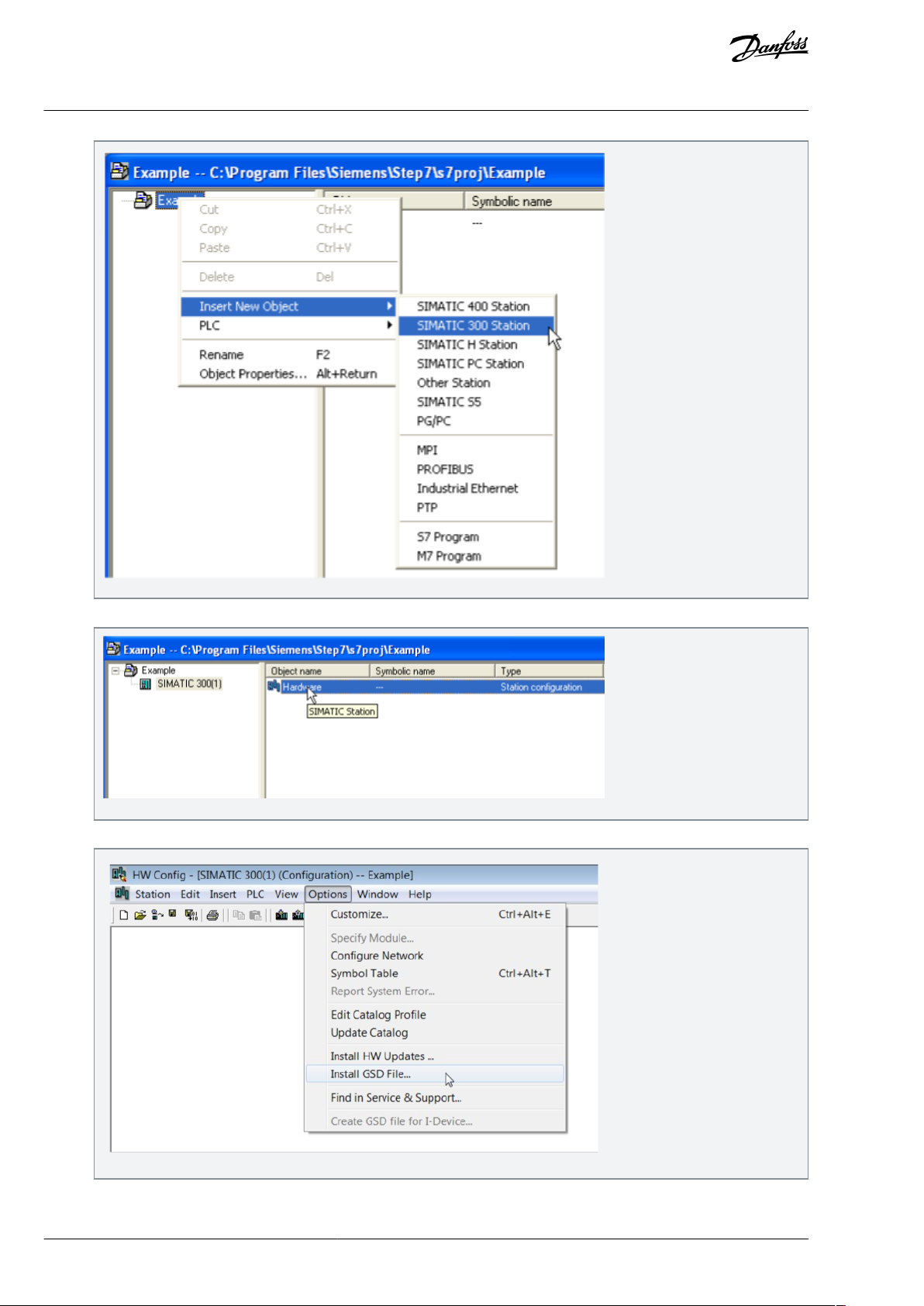
e30bh908.10
e30bh909.10
e30bh893.10
VACON® OPTEA/OPTE9 Ethernet Board
User Guide
Control Interface and
Communication
3.
To open the HW cong window, double-click Hardware.
4.
Install GSDML for VACON® device. Select Options-> Install GSD File…
5.
Browse to folder where you have stored GSDML les.
BC346130105092EN-US-000101 / DPD0158382 | Danfoss A/S © | 2020.06
Page 83

e30bh894.10
e30bh895.10
e30bh899.10
VACON® OPTEA/OPTE9 Ethernet Board
User Guide
6.
Select the required GSDML le(s) and click Install.
Control Interface and
Communication
After successful installation, this pop-up opens.
7.
Insert hardware information:
a.
Insert the rail.
BC346130105092EN-US-000101 / DPD01583 | 83Danfoss A/S © 2020.06
Page 84

e30bh910.10
e30bh911.10
e30bh912.10
VACON® OPTEA/OPTE9 Ethernet Board
User Guide
b.
Insert the supply.
Control Interface and
Communication
c.
Insert the CPU.
8.
Set the Ethernet interface properties:
BC346130105092EN-US-000101 / DPD0158384 | Danfoss A/S © | 2020.06
Page 85

e30bh913.10
e30bh914.10
VACON® OPTEA/OPTE9 Ethernet Board
User Guide
a.
Change the IP address.
b.
To select the subnet, click New.
Control Interface and
Communication
c.
d.
Click OK.
Click OK.
BC346130105092EN-US-000101 / DPD01583 | 85Danfoss A/S © 2020.06
Page 86

e30bh915.10
e30bh916.10
VACON® OPTEA/OPTE9 Ethernet Board
User Guide
Control Interface and
Communication
9.
Drag and drop the OPTEA to PROFINET I/O system.
BC346130105092EN-US-000101 / DPD0158386 | Danfoss A/S © | 2020.06
Page 87

e30bh942.10
e30bh943.10
VACON® OPTEA/OPTE9 Ethernet Board
User Guide
Control Interface and
Communication
10.
Select communication proles:
a.
Select a PROFIdrive communication prole.
b.
Select a PROFIsafe communication prole.
BC346130105092EN-US-000101 / DPD01583 | 87Danfoss A/S © 2020.06
Page 88

e30bh944.10
e30bh945.10
VACON® OPTEA/OPTE9 Ethernet Board
User Guide
Control Interface and
Communication
11.
To set up PROFISafe parameters, double-click the inserted safety telegram.
Set the same safe eldbus parameters as when creating the safety conguration with VACON® Safe PC tool. For example,
the F_iPar_CRC was calculated with the VACON® Safe PC tool.
12.
Change the option board properties.
BC346130105092EN-US-000101 / DPD0158388 | Danfoss A/S © | 2020.06
Page 89

e30bh946.10
e30bh947.10
VACON® OPTEA/OPTE9 Ethernet Board
User Guide
Control Interface and
Communication
13.
To verify the Device Name, select PLC -> Ethernet -> Verify Device Name.
14.
Set the I/O cycle.
BC346130105092EN-US-000101 / DPD01583 | 89Danfoss A/S © 2020.06
Page 90

e30bh948.10
e30bh939.10
VACON® OPTEA/OPTE9 Ethernet Board
User Guide
For details, see 4.4.9 Connection Timeout in PROFINET.
Control Interface and
Communication
4.4.10.2 Conguring with TIA Portal
Follow these instructions when conguring the Siemens S7-300 PLC series to use the VACON® OPTEA option board with the Siemens TIA Portal programming tool.
This example is with the OPTEA board. Process is identical with the OPTE9 board.
Check your individual PLC information. The information used in this example probably diers from local setup.
Conguring with TIA Portal
1.
Create a project.
2.
In the Create new project dialog, add name and location for the project and click Create.
BC346130105092EN-US-000101 / DPD0158390 | Danfoss A/S © | 2020.06
Page 91

e30bh940.10
e30bh941.10
e30bh949.10
VACON® OPTEA/OPTE9 Ethernet Board
User Guide
3.
When the project is created, click Project View from the lower left corner of the screen.
4.
Double-click Devices & networks .
Control Interface and
Communication
5.
Drag and drop the used Safety PLC.
6.
Add OPTEA option board.
BC346130105092EN-US-000101 / DPD01583 | 91Danfoss A/S © 2020.06
Page 92

e30bh950.10
e30bh951.10
e30bh952.10
VACON® OPTEA/OPTE9 Ethernet Board
User Guide
7.
To assign I/O controller, click the blue text Not assigned.
Control Interface and
Communication
8.
Assign the connections between the Ethernet ports in Topology view.
9.
Assign IP settings and Name of Station to the OPTEA option board.
BC346130105092EN-US-000101 / DPD0158392 | Danfoss A/S © | 2020.06
Page 93

e30bh953.10
e30bh954.10
e30bh955.10
VACON® OPTEA/OPTE9 Ethernet Board
User Guide
Control Interface and
Communication
10.
To open Device view, double-click OPTEA.
11.
Add the used telegrams to the Device overview:
a.
Drag and drop the used telegram to the conguration.
b.
Drag and drop used safety telegram to conguration.
BC346130105092EN-US-000101 / DPD01583 | 93Danfoss A/S © 2020.06
Page 94

e30bh956.10
e30bh957.10
e30bh958.10
VACON® OPTEA/OPTE9 Ethernet Board
User Guide
12.
Select the inserted safety telegram and set the safe eldbus parameters.
Set the same safe eldbus parameters as when creating the safety conguration with VACON® Safe PC tool. For example,
the F_iPar_CRC was calculated with the VACON® Safe PC tool.
Control Interface and
Communication
When the safety telegram is added, TIA Portal shows a yellow circle with a red dot to indicate that safety features
are used with this device.
BC346130105092EN-US-000101 / DPD0158394 | Danfoss A/S © | 2020.06
Page 95

e30bh959.10
e30bh960.10
A
B
C
VACON® OPTEA/OPTE9 Ethernet Board
User Guide
Loading the conguration to the PLC
1.
Select Online -> Download to device.
Control Interface and
Communication
2.
Select the PLC for loading:
a.
Use the dropdown menus to select the connection interface (how the PC with TIA Portal is connected to network
with the PLC).
b.
Click Search.
c.
Select the PLC and click Load.
The PLC shows in the list.
BC346130105092EN-US-000101 / DPD01583 | 95Danfoss A/S © 2020.06
Page 96

e30bh961.10
e30bh962.10
VACON® OPTEA/OPTE9 Ethernet Board
User Guide
TIA portal compiles the program.
Control Interface and
Communication
3.
To load the program to the PLC, click Load.
This view can contain more information when using safety.
4.
When the loading is ready, click Finish.
BC346130105092EN-US-000101 / DPD0158396 | Danfoss A/S © | 2020.06
Page 97

e30bh963.10
e30bh964.10
VACON® OPTEA/OPTE9 Ethernet Board
User Guide
The PLC starts communicating with the option board.
Control Interface and
Communication
4.4.10.3 Conguring with SIMATIC PDM
Follow these instructions when conguring the PROFINET connection with Siemens SIMATIC PDM.
This example is with the OPTEA board. Process is identical with the OPTE9 board.
Downloading EDD les
1.
Go to www.danfoss.com/.
2.
Select Downloads from Service and Support drop-down menu.
3.
Select Drives as business unit.
4.
Go to VLT® and VACON® eldbus conguration les.
5.
Download the EDD les for Siemens SIMATIC PDM.
Conguring with SIMATIC PDM
1.
Extract the zipped EDD les.
2.
Use PDM Device Integration Manager to read the EDD les into PDM catalog.
3.
Click the Integration button.
BC346130105092EN-US-000101 / DPD01583 | 97Danfoss A/S © 2020.06
Page 98

e30bh965.10
e30bh966.10
VACON® OPTEA/OPTE9 Ethernet Board
User Guide
OPTEA can now be used in PDM.
4.
To add OPTEA into a PDM project, select Pronet network and right-click and select Insert New Object.
Control Interface and
Communication
5.
Assign the Device Type, and select, for example, OPTEA, Vacon NX, Multi-Purpose.
BC346130105092EN-US-000101 / DPD0158398 | Danfoss A/S © | 2020.06
Page 99

e30bh967.10
e30bh968.10
VACON® OPTEA/OPTE9 Ethernet Board
User Guide
Control Interface and
Communication
6.
Set up the correct IP address that is used with the OPTEA option board.
7.
To access the drive parameters, open an object.
BC346130105092EN-US-000101 / DPD01583 | 99Danfoss A/S © 2020.06
Page 100

e30bh969.10
e30bh970.10
VACON® OPTEA/OPTE9 Ethernet Board
User Guide
Control Interface and
Communication
A view of uninitialized drive parameters opens.
8.
To download parameters into the PDM, select Device-> Upload to PG/PC.
9.
To start loading the parameter values, click Start. Then click Close after the process has nished.
BC346130105092EN-US-000101 / DPD01583100 | Danfoss A/S © | 2020.06
 Loading...