

Page 1

vacon
ac drives
optbk
as-interface option board
user manual
®
Page 2

Page 3

vacon • 1
INDEX
Document code(Original Instructions): DPD01311B
Revision release date: 22.5.15
1. OPTBK AS-interface board................................................................................2
1.1 General................................................................................................................................2
1.2 Technical data .....................................................................................................................2
1.2.1 AS-interface technical data ................................................................................................3
1.2.2 AS-i board layout and connections .....................................................................................4
1.2.3 Physical media ....................................................................................................................5
1.2.4 LED indications ...................................................................................................................6
2. Option board installation ..................................................................................7
2.1 Vacon 100 ............................................................................................................................7
2.2 Vacon 100 X .......................................................................................................................10
2.3 Vacon 20 X .........................................................................................................................14
Rev. B
24-hour support +358 (0)201 212 575 • Email: vacon@vacon.com
Page 4
vacon • 2 OPTBK AS-interface board
1. OPTBK AS-INTERFACE BOARD
1.1 General
The Actuator sensor Interface (AS-Interface or AS-i) is an economical system for the lower automation level. It is not a universal Fieldbus for all areas of automation. The AS-Interface is optimized
to network binary sensors and actuators to the higher control level.
The AS-Interface is an intelligent form of cabling rather than a true fieldbus. It does not replace
complex networks. Because the system has simple and cost-effective solutions, it suits well for the
Sensor/Actuator Level. The cost-effective, rugged AS-Interface components are especially suited
for use in harsh industrial environments. AS-i products are certified by the AS-International user
organization that guarantees worldwide compatibility. Vacon is AS-International member since
January 2013.
The installation of AS-interface is both easy and cost-effective. Because the AS-interface is a simple, defined electromechanical interface, no special expertise is necessary in the installation. It has
a quick "Snap and Go" cable penetration system. The installation is easy because the AS-interface
has freely selectable network topology. Also the configuration is easy. Only some prior knowlegde
is necessary for the assembly, which reduces downtime when faults occur.
The fault susceptibility of other systems often results in assembly delays, so the AS-Interface was
consciously designed to reduce error sources. The special profile of the AS-Interface cable prevents reversal of the poles when connecting devices.
1.2 Technical data
VACON® AC drives can be connected to the ASI bus system using a OPTBK AS-I board.
Internal components and circuit boards are at high potential when the AC drive is
connected to the power source. This voltage is extremely dangerous
and may cause death or severe injury if you come into contact with it.
The relay outputs and other I/O-terminals may have a dangerous control voltage
present even when the AC drive is disconnected from mains.
It is not allowed to add or replace option boards on an AC drive with
the power switched on. This may damage the boards.
NOTE! When experiencing problems with AS-I functionalities, please contact Fieldbus@vacon.com.
1
Tel. +358 (0) 201 2121 • Fax +358 (0)201 212 205
Page 5
OPTBK AS-interface board vacon • 3
1.2.1 AS-interface technical data
Master/Slave Communication System
AS-Interface profile S-7.A.7 (AS-i specifications 3.0)
Network type:
Topolo gy: Very flexible with Line, Bus, Star or Tree Topology
Installation:
Max. current
consumption:
Data Rate: 167 kBit/s
Max. Stations: 1 Master and up to 62 Slaves
Data: each Slave: - 4 bit digital Input and 4 bit digital Output Data
Network Features:
User Organization: AS-International
IO code 7
ID code A
ID1 code 7
ID2 code 7
Special (yellow) unshielded cable with 2 wires providing data and 30 V.
Alternatively data and power on separate cables 100 m length per
Segment, extendible up to 300 m with Repeaters
150 mA
Data values become refreshed at the slave in less than 21 ms; all 4
output bits operate simultaneously
Table 1. AS-interface technical data
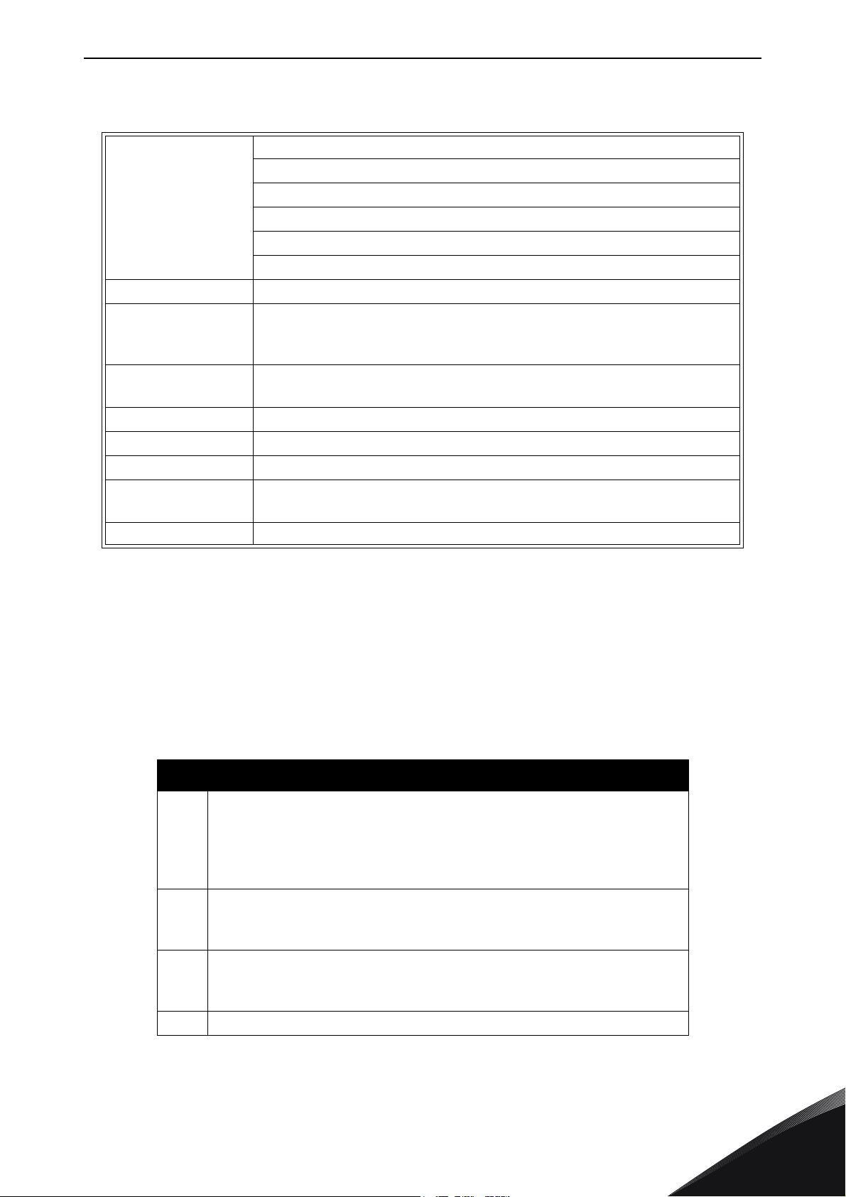
The AS-interface is a simple master-to-slave structure. The master controls all time and network
traffic. The protocol is embedded in the hardware. There are no configuration files to maintain. All
nodes are “AB Slaves”. The slaves have a maximum of 4 discrete input bits and 4 discrete output
bits. The address range is 1A-31A and 1B-31B, with 0 being reserved for new incoming slaves. “0”
is the default address set by manufacturers when a slave leaves the factory.
The board can be configured with the bits as the following table:
Parameter bits
Communication monitoring (Watchdog)
P0 = 0 monitoring = off, the outputs maintain the status if communi-
P0
P1
P2
P3 Not used
cation fails (default setting)
P0 = 1 monitoring = on, i.e. if communication fails, the outputs are
deenergised
Input filter
P1 = 0 input filter on, pulse suppression (default setting)
P1 = 1 input filter off
Synchronous mode
P2 = 0 synchronous mode on (default setting)
P2 = 1 synchronous mode off
Table 2. Description of parameter bit function.
24-hour support +358 (0)201 212 575 • Email: vacon@vacon.com
1
Page 6
vacon • 4 OPTBK AS-interface board
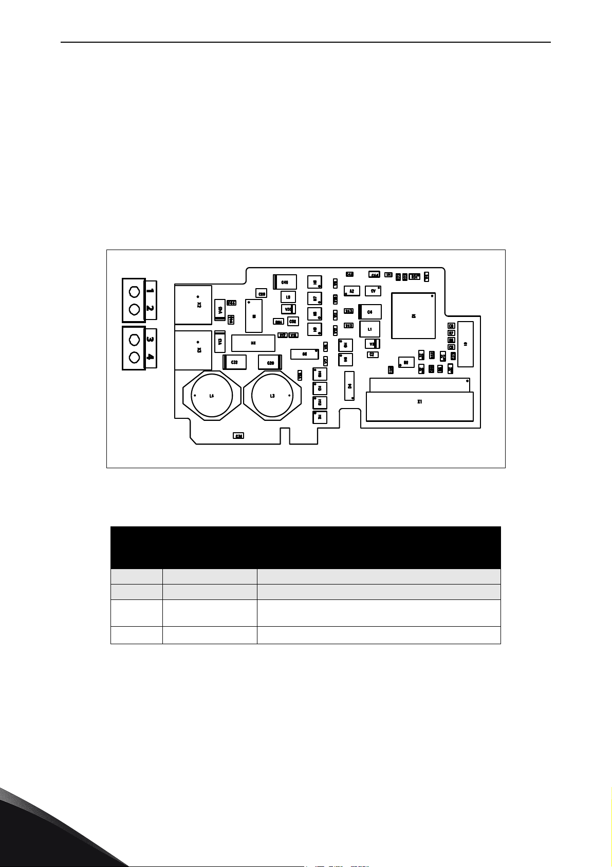
1.2.2 AS-i board layout and connections
Both data and power are supplied on the two-wire cable. The DC power carries the AS-interface signal. The AS-interface signal and the voltage regulating circuitry of the power supply must be separated.
Do not ground the AS-interface negative (ASI N). Grounding the signal lines results in poor communication or completely lost communication. The typical AS-interface media is not shielded. If shielding is necessary for the application, ground the shield in only one place.
The AS-interface power supply provides voltages in the 30VDC range (29.5-31.6 VDC). It is higher
than the industry standard nominal 24VDC to compensate for the voltage drop on the line as well
as the drop through the AS-interface IC chip.
Figure 1. OPTBK AS-interface option board.
OPTBK AS-interface terminals
Terminal Signal Technical information
1 ASI P AS-interface +
2 ASI N AS-interface -
ASI Supply P
3
ASI Supply N GND of Auxiliary output voltage
4
Table 3. OPTBK AS-Interface terminals
Auxiliary output voltage (ASi voltage input - max 2.4V at
maximum output current)
1
Tel. +358 (0) 201 2121 • Fax +358 (0)201 212 205
Page 7

OPTBK AS-interface board vacon • 5
A
A
2(N.C.)
Male M12 Female M12
4(N.C.)
Brown
Blue
1.2.3 Physical media
AS-interface is available in both flat cable with IDC (Insulation Displacement Cable) connectors or
round cable with industry standard M12 EN50 044 connectors.
SI P
SI N
Figure 2.AS-interface Flat Cable. Right figure shown with piercing teeth.
Cross section of the wires
EU US
2 x 15 mm
2
2 x 18 AWG
Table 4. Cross sectional size of the wires.
1 - ASI P
3 - ASI N
Figure 3. AS-interface round cable with industry standard M12 EN50 044 connector.
24-hour support +358 (0)201 212 575 • Email: vacon@vacon.com
1
Page 8

vacon • 6 OPTBK AS-interface board
1.2.4 LED indications
There are two LED indications next to the connector on the bottom side of the option board as show
in the picture below.
Figure 4. LED position on the option board.
LED indications
Green LED is: Red LED is: Meaning Note
OFF OFF
ON OFF
ON ON
Flashing ON
ON Flashing
Power OFF No power supply available
Normal Operation Data communication is established
No data exchange IC is waiting for a Write_Parameter request.
No data exchange
(Address = 0)
Periphery
Fault
Table 5. LED indications.
Slave is waiting for address assignment.
Data Port communication is not possible.
Communication Error
1
Tel. +358 (0) 201 2121 • Fax +358 (0)201 212 205
Page 9

Option board installation vacon • 7
M4x55
9174.emf
3023.emf
2. OPTION BOARD INSTALLATION
2.1 Vacon 100
Open the cover of the AC drive.
1
To get access to the option board slots, open the cover of the control unit.
2
24-hour support +358 (0)201 212 575 • Email: vacon@vacon.com
2
Page 10

vacon • 8 Option board installation
DE
3024.emf
9068.emf
Install the option board into correct slot D or E.
The option board has a slot coding, and thus it is not possible to install the option
board in an incorrect slot.
3
4
5
Close the cover of the control unit.
In IP21, cut free the opening on the cover of the AC drive for the AS-I cable.
In IP54, cut a hole in a grommet and move the cable through it. Make the connection tight.
2
Tel. +358 (0) 201 2121 • Fax +358 (0)201 212 205
Page 11

Option board installation vacon • 9
9202.emf
Fieldbus
cables
6
7
8
Install AS-interface cables and other cables.
Close the cover of the AC drive.
Pull the AS-interface cable to the side. Move the cable away from the mains cable
and the motor cable.
24-hour support +358 (0)201 212 575 • Email: vacon@vacon.com
2
Page 12

vacon • 10 Option board installation
11638_00
2.2 Vacon 100 X
Open the cover of the AC drive.
1
2
Tel. +358 (0) 201 2121 • Fax +358 (0)201 212 205
Page 13

Option board installation vacon • 11
11639_00
To get access to the option board slots, remove the screws and open the cover of
the control unit.
2
24-hour support +358 (0)201 212 575 • Email: vacon@vacon.com
2
Page 14

vacon • 12 Option board installation
DE
11640_00
11641_00
Install the option board into the correct slot, D or E.
3
4
5
Close the option board cover.
Remove the cable entry plate. If you
installed the option board in the slot
D, use the cable entry plate on the
right side. If you installed the option
board in the slot E, use the cable entry plate on the left side.
NOTE! The cable entry plate at the
bottom of the drive is used only for
mains and motor cables.
2
Tel. +358 (0) 201 2121 • Fax +358 (0)201 212 205
Page 15

Option board installation vacon • 13
11642_00
6
7
Open the necessary holes in the cable entry plate. Do not open the other holes.
See the Vacon 100X Installation Manual for the dimensions of the holes.
Attach a cable gland on the hole in the cable entry plate. Pull the AS-interface cable
through the hole.
NOTE! The AS-interface cable must go
through the correct cable entry plate to
avoid going near the motor cable.
8
9
Put the cable entry plate back.
Close the cover of the AC drive.
24-hour support +358 (0)201 212 575 • Email: vacon@vacon.com
2
Page 16

vacon • 14 Option board installation
11643_00
7089_00
2.3 Vacon 20 X
NOTE! It is not allowed to add or replace option boards or fieldbus boards on an AC
drive with the power switched on. This may damage the boards.
The relay outputs and other I/O-terminals may have a dangerous control voltage
present even when the drive is disconnected from mains.
Open the cover of the drive.
1
2
Remove the option slot cover.
2
Tel. +358 (0) 201 2121 • Fax +358 (0)201 212 205
Page 17

Option board installation vacon • 15
7090_00
7091_007091_00
3
NOTE: Incompatible boards cannot be installed on Vacon 20X. Compatible boards
have a slot coding that enable the placing of the board (see above)
4
Install the option board into the slot as shown in the picture below.
Mount the option slot cover.
5
24-hour support +358 (0)201 212 575 • Email: vacon@vacon.com
2
Page 18

Find your nearest Vacon office
on the Internet at:
www.vacon.com
Manual authoring:
documentation@vacon.com
Vacon Plc.
Runsorintie 7
65380 Vaasa
Finland
Subject to change without prior notice
© 2015 Vacon Plc.
Document ID:
Rev. B
Sales code: DOC-OPTBK+DLUK
 Loading...