


vacon® nxs/p
ac drives
flange mounting kit
for fr7-fr9
installation manual

2 • vacon Flange mounting kit FR7-FR9
Document code: DPD01880B
Date: 02.10.2017
INDEX
1. General .............................................................................................................................. 3
2. Vacon Flange Mounting Kit contents .................................................................................. 4
3. Installation ......................................................................................................................... 6
3.1 FR7 .............................................................................................................................................. 6
3.2 FR8 .............................................................................................................................................. 8
3.3 FR9 .............................................................................................................................................. 9
4. Mounting .......................................................................................................................... 10
5. Information sticker .......................................................................................................... 11
Local contacts: http://drives.danfoss.com/danfoss-drives/local-contacts/
Flange mounting kit FR7-FR9 vacon • 3
1
Cabinet
IP54
IP21
1. GENERAL
Using the VACON® Flange Mounting Kit, you can mount your VACON® NX AC drive through the
cabinet wall so that the control unit of the drive remains inside the cabinet.
The correct installation of the Flange Mounting Kit affects the IP protection class of the frequency
converter. After the installation, the control unit is protected according to IP21 and the power unit
according to IP54 (unless the frequency converter was originally IP21-protected). See figure below.
According to standard IEC 60529 (EN 60529), the IP54 AC drive enclosure provides protection against
dust and water sprayed from all directions. Limited ingress of both is permitted.
Local contacts: http://drives.danfoss.com/danfoss-drives/local-contacts/
4 • vacon Flange mounting kit FR7-FR9
2
1
2
3
4
5
5
4
6
3
1 Flange, top
3 Flange, side
4 Screws (5x10 TF)
6 Sealing tape
1
2
3
4
4
5
3
1 Flange, top
3 Flange, side
4 Screws (4x8 TF)
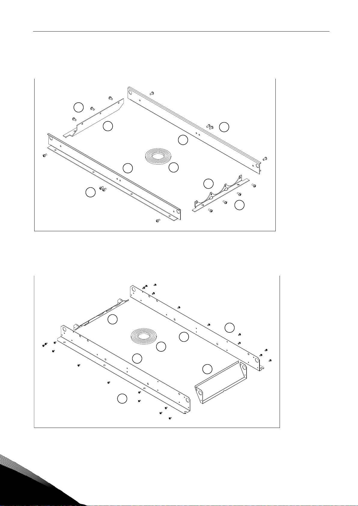
2. VACON
®
FLANGE MOUNTING KIT CONTENTS
The contents of the Flange Mounting Kits for different frames are shown in the following pictures.
FR7:
FR8:
2 Flange, bottom
2 Flange, bottom
5 Screws (5x10 TX)
5 Sealing tape
Local contacts: http://drives.danfoss.com/danfoss-drives/local-contacts/

Flange mounting kit FR7-FR9 vacon • 5
2
1
2
3
4
4
4
4
5
3
1 Flange, top
3 Flange, side
4 Screws (5x10 TX)
FR9:
2 Flange, bottom
5 Sealing tape
Local contacts: http://drives.danfoss.com/danfoss-drives/local-contacts/

6 • vacon Flange mounting kit FR7-FR9
3
both sides of the AC drive.
top of the AC drive.
with 5x10 Torx screws
(5x10 TF) in the upper corners.
in the middle
remaining screws (5x10 TF).
3. INSTALLATION
These instructions guide you through the installation of the Flange Mounting Kit that you have
purchased for your FR7, FR8 or FR9 size AC drive.
NOTE! The sealant to be used in the flange mounting kit installation is flame retardant silicone
sealant (e.g. Sika Firesil -N)
3.1 FR7
1. Remove the three screws from
4. Attach the top flange with three
5x10 TF screws.
2. Remove also three screws from the
5. Seal the two holes and the
sides in the bottom of the AC drive.
3. Attach the side flange to both sides
6. Fix the cable entry flange to
its place. Attach first the screws
7. Seal the bottom flange.
8. Attach the bottom flange. Fasten
first only the two screws (5x10 TF)
9. Seal the sides of the cable entry
flange. Then attach the two
Local contacts: http://drives.danfoss.com/danfoss-drives/local-contacts/

Flange mounting kit FR7-FR9 vacon • 7
3
converter.
corner.
seams.
7. Seal the sides of the frequency
10. Smoothen all sealed seams
with your finger. Tip your finger in
soap water before smoothening the
8. Seal the top flange.
9. Seal the small seams in each
Local contacts: http://drives.danfoss.com/danfoss-drives/local-contacts/

8 • vacon Flange mounting kit FR7-FR9
3
the right side of the AC drive.
screws (4x8 TF).
middle screw from this side.
screws (4x8 TF).
picture.
3.2 FR8
1. Remove these five screws from
4. Repeat the steps 1-3 with the left
side flange. Remove also the
2. Apply sealant to the right side flange. 3. Attach the right side flange with five
5. Seal the bottom flange with
sealing tape and attach it with four
6. Seal the top flange with sealant.
7. Attach the top flange with five
screws (4x8 TF). See also the next
8. Seal all seams of the top and
bottom flanges with sealant.
Local contacts: http://drives.danfoss.com/danfoss-drives/local-contacts/

Flange mounting kit FR7-FR9 vacon • 9
3
fasten it with four screws (5x10 TX).
TX).
(5x10 TX).
step 5.
3.3 FR9
1. Before attaching the side
flanges check that they are in the
correct order. If the inner hole is
not showing the flange is on the
wrong side.
4. Fasten the sides of the top
flange with two screws/side (5x10
2. Seal the side flanges with
sealant and attach them with 7
(5x10 TX) screws each.
5. Carefully seal all the seams of
the top flange with sealant.
3. Seal the top flange with sealant and
6. Seal the bottom flange with
sealant and attach it four screws
7. Fasten the sides of the bottom
flange with two screws/side (5x10
TX). Seal all seams as shown in
Local contacts: http://drives.danfoss.com/danfoss-drives/local-contacts/

10 • vacon Flange mounting kit FR7-FR9
4
4. MOUNTING
MOUNTING PROCEDURE
1. Make an opening in the cabinet door for the flange (collar) installation using the dimensions
given in VACON
2. Attach the sealing tape around the opening. See Figure 1 for how to bend the tape at the corners
of the opening (1) and place the tape so that it runs
The kit contains a greater amount of tape than what you might need. Only use such an amount of
tape required by the dimensions of the opening.
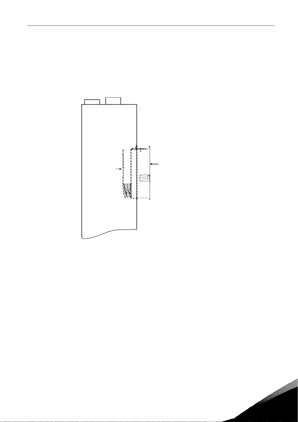
3. Fit the AC drive in the opening.
NOTE! The AC drive will not fit in the opening in a straight position. Tip the drive positioning the
lower end first in the opening. See Figures 2 and 3.
Fix the AC drive on the plane with the screws included in the kit (FR7: M5 screws / FR8: M6 screws,
FR9: M5 screws).
®
NX User's manual, chapter 5.
inside
the screws (2).
Figure 1
Figures 2 and 3
Local contacts: http://drives.danfoss.com/danfoss-drives/local-contacts/

11 • vacon Flange mounting kit FR7-FR9
5
D
r
i
v
e
m
o
d
i
f
i
e
d
:
Option board:
NXOPT................
I
P5
4
u
pg
r
ad
e/
C
ol
la
r
in slot:
D
at
e:
.
..
.
..
..
.
..
..
.
..
..
.
A
B
C
D
E
E
M
C
le
v
el
m
o
di
fi
e
d:
H
to
T
/
T
t
o
H
D
a
t
e
:
.
.
.
.
.
.
.
.
.
.
.
.
.
.
.
.
.
.
.
Date:...........
..
.
..
..
.
1
2
5. INFORMATION STICKER
Each Flange Mounting Kit delivered by the factory includes a sticker (shown below).
Please check
IP54/Collar
(1) and mark the installation date (2) on the sticker. Finally, attach the
sticker on the drive.
Local contacts: http://drives.danfoss.com/danfoss-drives/local-contacts/

www.danfoss.com
Vacon Ltd
Member of the Danfoss Group
Runsorintie 7
65380 Vaasa
Finland
Document ID:
DPD01880B
Rev. B
 Loading...