

Page 1

vacon nxp
®
ac drives
grid converter
application manual
arfiff03
Page 2

Page 3

arfiff03 Grid Converter VACON® · 3
Local contacts: http://drives.danfoss.com/danfoss-drives/local-contacts/
Classified as Public
Table of contents
Document: DPD01599C
Software code: ARFIFF03V164
Version release date: 31.5.2021
1. General ................................ ................................................................................................ .... 8
1.1 AFE Control ............................................................................................................................... 8
1.2 Island (Static Power Supply) .................................................................................................... 8
1.3 Micro Grid.................................................................................................................................. 9
1.4 Shaft Generator ...................................................................................................................... 10
1.5 Acronyms ................................................................................................................................ 11
1.6 Compatibility issues in parameters between versions ........................................................ 12
2. Quick start and operation principles ..................................................................................... 13
2.1 Quick start instructions.......................................................................................................... 13
2.2 In case of parallel AFE: .......................................................................................................... 13
2.3 Pre-Charging of DC ................................................................................................................ 15
2.4 Main circuit breaker control (MCB) ....................................................................................... 16
2.5 Start Sequence ....................................................................................................................... 17
2.6 Stop sequence ........................................................................................................................ 18
2.7 afe mode; Start Stop timing diagram .................................................................................... 19
2.8 Operation principle: Droop Speed Control Mode ................................................................. 20
2.9 Operation principle: Isochronous Speed Control Mode ....................................................... 20
2.10 Voltage compensation ............................................................................................................ 21
2.11 OPT-D7 .................................................................................................................................... 22
2.12 Master Follower ..................................................................................................................... 23
2.12.1 General ....................................................................................................................... 23
2.12.2 Grid Converter Standard master follower ................................................................ 23
2.12.3 Grid Converter DriveSynch ........................................................................................ 23
2.12.4 Grid Converter D2-Synch ........................................................................................... 23
3. Control I/O ............................................................................................................................. 25
3.1 Slot A and Slot B terminals .................................................................................................... 25
3.2 Terminal To Function (TTF) ................................................................................................... 25
3.3 Defining inputs and outputs ................................................................................................... 26
3.4 Defining a terminal in NCDrive .............................................................................................. 27
4. Monitoring signals ................................................................................................................. 28
4.1 Monitoring value tables.......................................................................................................... 28
4.1.1 Monitoring values 1 .................................................................................................... 28
4.1.2 Monitoring values 2 .................................................................................................... 29
4.1.3 Fieldbus monitoring values ....................................................................................... 29
4.1.4 I/O monitoring values ................................................................................................. 30
4.1.5 Master/Follower ......................................................................................................... 30
4.1.6 Licence key activation ................................................................................................ 30
4.1.7 Line Monitoring .......................................................................................................... 30
4.1.8 Active Limits ............................................................................................................... 31
4.1.9 PI Power Controller ................................................................................................... 31
Page 4

4 · VACON® arfiff03 Grid Converter
Local contacts: http://drives.danfoss.com/danfoss-drives/local-contacts/
Classified as Public
4.2 Description of monitoring values .......................................................................................... 32
4.2.1 Monitoring 1 values .................................................................................................... 32
4.2.2 Monitoring 2 values .................................................................................................... 35
4.2.3 Fieldbus monitoring values ....................................................................................... 37
4.2.4 I/O monitoring values ................................................................................................. 43
4.2.5 Master Follower ......................................................................................................... 44
4.2.5.1 Currents ................................................................................................................... 45
4.2.5.2 Statuses .................................................................................................................... 46
4.2.6 Activation status ......................................................................................................... 47
4.2.7 Line Monitoring .......................................................................................................... 48
4.2.8 Active Limits ............................................................................................................... 48
4.2.9 PI Power Controller ................................................................................................... 48
5. Parameter list ........................................................................................................................ 49
5.1 Basic parameters ................................................................................................................... 49
5.2 Reference handling ................................................................................................................ 49
5.2.1 DC Reference Tuning ................................................................................................. 50
5.2.2 Power / Frequency reference ................................................................................... 50
5.2.3 PID Power Controller for AFE ................................................................................... 50
5.2.4 Reactive Reference .................................................................................................... 51
5.2.5 AC voltage reference ................................................................................................. 52
5.3 Ramp control .......................................................................................................................... 52
5.4 Input signals ........................................................................................................................... 52
5.4.1 Basic settings ............................................................................................................. 52
5.4.2 Digital inputs .............................................................................................................. 53
5.4.3 Analogue input 1 ........................................................................................................ 54
5.4.4 Analogue input 2 ........................................................................................................ 54
5.4.5 Analogue input 3 ........................................................................................................ 54
5.4.6 Analogue input 4 ........................................................................................................ 55
5.5 Output signals ......................................................................................................................... 55
5.5.1 Digital output signals ................................................................................................. 55
5.5.2 Delayed DO 1 .............................................................................................................. 56
5.5.3 Delayed DO 2 .............................................................................................................. 56
5.5.4 Analogue output 1 ...................................................................................................... 57
5.5.5 Analogue output 2 ...................................................................................................... 58
5.5.6 Analogue output 3 ...................................................................................................... 59
5.5.7 Options ........................................................................................................................ 59
5.6 Limit settings .......................................................................................................................... 60
5.6.1 Current limit ............................................................................................................... 60
5.6.2 Power limit ................................................................................................................. 60
5.6.3 Frequency limit .......................................................................................................... 60
5.6.4 Micro Grid ................................................................................................................... 60
5.6.5 DC voltage ................................................................................................................... 61
5.7 Drive control ........................................................................................................................... 61
5.7.1 AFE control ................................................................................................................. 61
5.7.2 Identification ............................................................................................................... 62
5.7.3 Active Compensation ................................................................................................. 62
Page 5

arfiff03 Grid Converter VACON® · 5
Local contacts: http://drives.danfoss.com/danfoss-drives/local-contacts/
Classified as Public
5.8 Master/Follower ..................................................................................................................... 62
5.9 Protections .............................................................................................................................. 63
5.9.1 General ....................................................................................................................... 63
5.9.2 Temperature Sensor Protections ............................................................................. 64
5.9.3 Earth fault ................................................................................................................... 64
5.9.4 Fieldbus fault .............................................................................................................. 64
5.9.5 External fault .............................................................................................................. 65
5.9.6 Grid voltage D7 ........................................................................................................... 65
5.9.7 Grid frequency ............................................................................................................ 65
5.9.8 Voltage ........................................................................................................................ 65
5.9.9 Over Load .................................................................................................................... 66
5.9.10 D7 Protections ............................................................................................................ 66
5.9.11 Cooling protection ...................................................................................................... 66
5.9.12 Extra ............................................................................................................................ 66
5.10 Fieldbus ................................................................................................................................... 67
5.11 Micro Grid................................................................................................................................ 69
5.11.1 Free Select ................................................................................................................. 69
5.12 Synchronisation to external grid ........................................................................................... 70
5.13 Reserved ................................................................................................................................. 70
5.14 ID control functions ................................................................................................................ 71
5.14.1 Value control .............................................................................................................. 71
5.14.2 DIN ID control 1 .......................................................................................................... 71
5.14.3 DIN ID control 2 .......................................................................................................... 71
5.14.4 DIN ID control 3 .......................................................................................................... 72
5.14.5 DIN ID control 4 .......................................................................................................... 72
5.14.6 Signal Fault function .................................................................................................. 72
5.14.7 ID Controlled Digital Output 1 ................................................................................... 72
5.14.8 ID Controlled Digital Output 1 ................................................................................... 72
5.15 Auto reset ................................................................................................................................ 73
5.16 Grid voltage PI ........................................................................................................................ 73
5.17 Keypad control (M3) ............................................................................................................... 73
5.18 System menu (M6) .................................................................................................................. 73
5.19 Expander boards (M7) ............................................................................................................ 73
6. Description of parameters..................................................................................................... 74
6.1 Basic parameters ................................................................................................................... 74
6.1.1 Transformer parameters .......................................................................................... 76
6.2 Reference handling ................................................................................................................ 77
6.2.1 DC Reference Tuning ................................................................................................. 78
6.2.2 Power / Frequency reference ................................................................................... 79
6.2.3 PID Power Controller ................................................................................................. 82
6.2.4 Reactive Current Reference ...................................................................................... 83
6.2.5 AC Voltage Reference ................................................................................................ 84
6.3 Ramp control .......................................................................................................................... 86
6.4 Input signals ........................................................................................................................... 88
6.4.1 Basic settings ............................................................................................................. 88
6.4.2 Digital input signals ................................................................................................... 89
Page 6

6 · VACON® arfiff03 Grid Converter
Local contacts: http://drives.danfoss.com/danfoss-drives/local-contacts/
Classified as Public
6.4.2.1 Synchronization to external grid ............................................................................... 91
6.4.2.2 Forced control place ................................................................................................. 93
6.4.3 Analogue inputs 1-4 ................................................................................................... 95
6.4.3.1 Analogue input to any parameter ............................................................................. 97
6.5 Output signals ......................................................................................................................... 98
6.5.1 Digital output signals ................................................................................................. 98
6.5.1.1 Fieldbus digital inputs connection ............................................................................. 99
6.5.2 Delayed digital output 1 & 2 .................................................................................... 100
6.5.3 Analogue output 1 & 2 & 3 ....................................................................................... 102
6.5.4 Options ...................................................................................................................... 105
6.6 Limit settings ........................................................................................................................ 107
6.6.1 Current limits ........................................................................................................... 107
6.6.2 Power limits.............................................................................................................. 111
6.6.3 Frequency limits....................................................................................................... 112
6.6.4 Micro Grid limits ....................................................................................................... 113
6.6.5 DC voltage regulators .............................................................................................. 114
6.7 Drive control ......................................................................................................................... 116
6.7.1 AFE Control .............................................................................................................. 121
6.7.2 Identification ............................................................................................................. 122
6.7.3 Active Compensation ............................................................................................... 122
6.8 Master Follower ................................................................................................................... 123
6.9 Protections ............................................................................................................................ 125
6.9.1 General settings ....................................................................................................... 125
6.9.2 Temperature Sensor Protections ........................................................................... 129
6.9.2.1 Individual channel monitoring ................................................................................ 131
6.9.3 Earth fault ................................................................................................................. 132
6.9.4 Fieldbus .................................................................................................................... 133
6.9.5 External fault ............................................................................................................ 133
6.9.6 Grid voltage D7 ......................................................................................................... 133
6.9.7 Grid frequency .......................................................................................................... 135
6.9.8 Supply voltage .......................................................................................................... 136
6.9.9 Over Load Protection ............................................................................................... 138
6.9.10 D7 protections .......................................................................................................... 139
6.9.11 Cooling protection .................................................................................................... 140
6.9.12 Extra .......................................................................................................................... 141
6.10 Fieldbus ................................................................................................................................. 142
6.11 Micro Grid (uGrid) ................................................................................................................. 145
6.11.1.1 Generator Simulation ........................................................................................... 147
6.11.1.2 AFE operation mode selection .............................................................................. 148
6.12 Synch to external grid .......................................................................................................... 149
6.13 Reserved ............................................................................................................................... 150
6.14 ID functions ........................................................................................................................... 151
6.14.1 Value control ............................................................................................................ 151
6.14.2 DIN ID control ........................................................................................................... 153
6.14.3 Signal Fault Function ............................................................................................... 154
6.14.4 ID Controlled Digital Output .................................................................................... 155
6.15 Auto Reset ............................................................................................................................. 156
6.16 Grid voltage PI controller ..................................................................................................... 157
Page 7

arfiff03 Grid Converter VACON® · 7
Local contacts: http://drives.danfoss.com/danfoss-drives/local-contacts/
Classified as Public
6.16.1 Grid voltage PI OPT-D7 limits ................................................................................. 157
7. Keypad control parameters ................................................................................................. 158
8. FB Status and control in detail ............................................................................................ 159
8.1 FB DC Reference .................................................................................................................. 159
8.2 State machine: Basic............................................................................................................ 160
8.2.1 FB Control Word Basic ............................................................................................ 160
8.3 State Machine: Standard ...................................................................................................... 161
8.3.1 Control Word: Standard ........................................................................................... 161
8.4 State machine: Vacon AFE 1 ................................................................................................ 162
8.4.1 Control Word: Vacon AFE 1 ..................................................................................... 162
8.5 State machine: Vacon AFE 2 ................................................................................................ 163
8.5.1 Control Word: Vacon AFE 2 Profile (3) .................................................................... 163
8.6 FB Status Word ..................................................................................................................... 165
8.7 FB Micro Grid Control Word 1 ID1700 ................................................................................. 167
9. Problem solving ................................................................................................................... 168
10. Commissioning .................................................................................................................... 169
10.1 Open loop voltage compensation ........................................................................................ 169
10.1.1 Parameters affect .................................................................................................... 169
10.1.2 No load tuning .......................................................................................................... 169
10.1.3 Tuning on the fly ....................................................................................................... 169
10.1.4 Tuning with load bank .............................................................................................. 170
10.1.5 Tuning against strong grid ...................................................................................... 170
10.1.6 Closed Loop Voltage Control ................................................................................... 170
11. Fault codes .......................................................................................................................... 171
Page 8
8 · VACON® arfiff03 Grid Converter
Local contacts: http://drives.danfoss.com/danfoss-drives/local-contacts/
1
Classified as Public
1. General
This application is not kept backwards compatible. See chapter Compatibility issues before you
update the application. The Grid Converter application is used to make AC grids with a possibility to
operate in parallel with other power sources. The Grid Converter application has 3 different operation
modes:
- Standard AFE mode.
- Island mode.
- Micro Grid mode.
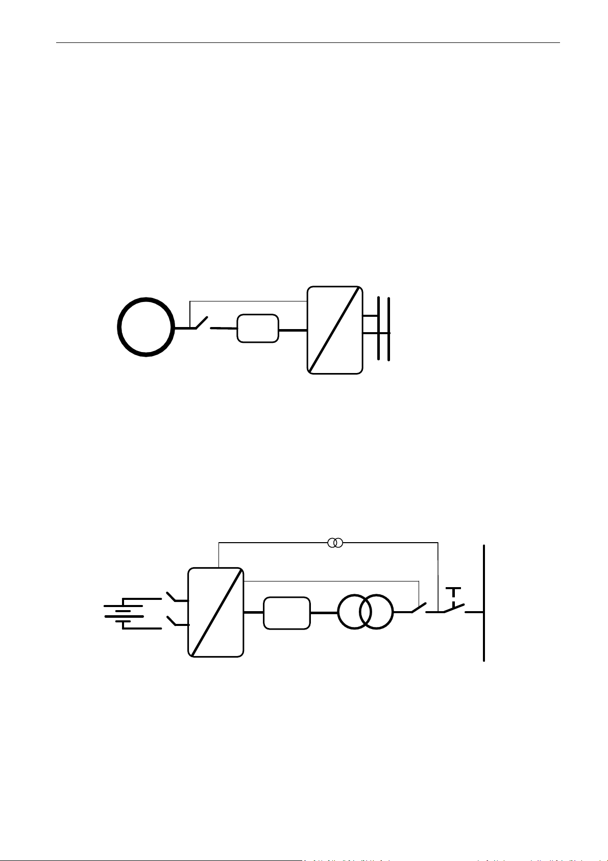
1.1 AFE Control
AFE function keeps constant DC voltage. AFE mode transfers power between DC and AC. AFE
cannot create grid by itself, it needs to be connected to existing grid.
U2
=
~
Filter
G1
U1
Q2
UDC
MCB Control
Figure 1.
1.2 Island (Static Power Supply)
Island mode generates constant voltage and frequency. In island mode DC Voltage is not controlled.
Island mode cannot operate in parallel with other power sources in AC side, because the drive will
not balance reactive or active power with other power sources.
DC voltage level needs to be considered to have correct voltage on AC side in different load
situations, considering voltage losses in LCL filter and in transformer.
T1
Q1
U4
U3
U5
=
~
Filter
U4 = Transf. GC Side
U5 = Transf. Grid Side
D7
S1
D Y
T2
MCB Control
Grid
Figure 2.
Page 9

arfiff03 Grid Converter VACON® · 9
Local contacts: http://drives.danfoss.com/danfoss-drives/local-contacts/
1
Classified as Public
1.3 Micro Grid
Micro Grid mode controls the grid voltage and frequency. It functions like an ordinary generator.
Micro Grid mode does not control DC Voltage.
With the help of voltage droop and frequency droop, more than one Micro Grid and/or Generators
can work together.
Q1
=
~
Filter
U4 = Transf. GC Side
U5 = Transf. Grid Side
T1
S1
Q1
U4
U3
U5
=
~
Filter
U4 = Transf. GC Side
U5 = Transf. Grid Side
D7
S1
G1
Q2
U4
U5
U3
T1
D7
D Y
T2
D Y
T2
MCB Control
MCB Control
Ship Grid
Figure 3.
Page 10

10 · VACON® arfiff03 Grid Converter
Local contacts: http://drives.danfoss.com/danfoss-drives/local-contacts/
1
Classified as Public
1.4 Shaft Generator
The shaft generator is a system where the generator is connected to the main engine shaft that also
runs the main propulsion. The disadvantage is that the main engine must run at nominal speed even
if full power to the propeller is not necessary.
With the shaft generator system power goes through the drives. One converts power from the
generator to DC link, and the other makes a ship grid with constant 50 Hz or 60 Hz, thus there is no
direct connection to the generator. The main engine can run at a more efficient speed without
changing grid frequency.
One drive operates as an AFE on the generator side and the other operates on Island mode or Micro
Grid mode on the grid side.
- The start command to generator side drive.
- Both drives can make DC charging if powered by +24 Vdc.
- When DC is at an 80% of nominal, the generator side and the grid side breakers close.
- The generator side AFE is started to boost DC first.
- The grid side Grid Converter is started and will synchronise to grid.
- The drives take power from the bypass, and the PMS opens the SG contactor.
- You can decrease the speed of the main diesel engine to be more economical.
NOTE! If it is necessary to have these systems in parallel, the system bus communication is
reserved for parallel Micro Grid units on the grid side. The control must be arranged separately for
each drive.
G1
T3
Auxilliary loads
including single
phase loads
D Y
T2
Ship Grid
U4
U3
UDC
U2
=
~
=
~
Filter
Filter
ST
BT
G2
SG
U5
Q2
Q4
U5
Q1 Q3
D7
T1
MCB Control
MCB Control
Figure 4.
Page 11

arfiff03 Grid Converter VACON® · 11
Local contacts: http://drives.danfoss.com/danfoss-drives/local-contacts/
1
Classified as Public
1.5 Acronyms
AC = Alternating Current
AI = Analogue Input
AIO
=
All-In-One Applications
AM = Asynchronous Motor
ASIC
=
Application Specific Integrated Circuit
CL = Closed Loop
DC = Direct Current
DI = Digital Input
DO = Digital Output
DS = DriveSynch
FB = Field Bus
FFT
=
Function To Terminal
FW = Firmware
FWP
=
Field Weakening Point
FWPV
=
Field Weakening Point Voltage
GE = Greater or Equal
HW = Hardware
I/f
=
Current / Frequency
Id = Magnetization Current
IGBT
=
Insulated Gate Bipolar Transistor
INV
=
Inversion
Iq = Torque Producing Current
LT = Less Than
MF = Master-Follower
OL = Open Loop
PID
=
Proportional Integral Derivative
PM = Permanent Magnet
PMSM
=
Permanent Magnet Synchronous Motor
PU = Per Unit
RO = Relay Output
RS = Reset Set
SB = System Bus
Sep.Ex SM
=
Separately Excitated Synchronous Motor
SM = Synchronous Machine
SPC
=
Speed Control
SQS
=
Sfe Quick Stop
SR = Set Reset
SRM
=
Synchronous Reluctance Motor
SS1
=
Safe Stop 1
STO
=
Safe Torque Off
SW = Software
TC = Torque Control
TC = Time Constant
TTF
=
Terminal To Function
U/f
=
Voltage / Frequency
UV = Under Voltage
Page 12

12 · VACON® arfiff03 Grid Converter
Local contacts: http://drives.danfoss.com/danfoss-drives/local-contacts/
1
Classified as Public
1.6 Compatibility issues in parameters between versions
Update Note 1: This application parameters are not kept backwards compatible if new features or
improvements would be difficult to implement by doing so. Read this change note and chapter
“Compatibility issues in parameters between versions” from manual before updating the application.
Update Note 2: It’s recommended to use compare function for parameter changes when updating
application, especially in cases when version number change is considerably high.
Application is constantly developed; this includes changing parameter default values, and if
parameters are directly downloaded to drive improved default values may be lost.
Update Note 3: If OPT-D7 PI voltage control is needed in uGrid mode, do not use versions V082 or
V083.
V092
• Major Compatibility Issue: P2.1.7 System Nom. DC is initialized to unit nominal DC value.
▪ 500 Vac unit: 675 Vdc
▪ 690 Vac unit: 931 Vdc
o When the transformer ratio was other than 1:1: MCB closing limit and DC-Link Voltage
reference values were based on grid voltage after transformer. This was causing reference
handling problems when given AC values were in range of different voltage class unit.
o DC Voltage Reference in AFE mode is based always to System Nom DC parameter.
V089
o Compatibility Issue: Voltage MotPot is adjusting now field weakening point voltage. Units have
been changed from [V] to [%]. This enables more accurate adjustment and adjustment rate.
V087
o Minor Compatibility Issue: FB Actual Speed signal changed to use Filtered DC-Link Voltage
signal (ID1108) instead of unfiltered DC Voltage signal.
V081
o Compatibility Issue: Parameters “PID Activation” and “FreqScaleMinAO” had same ID1807.
“FreqScaleMinAO” DI changed to ID1809.
o Major Compatibility Issue: Fieldbus State Machine
o See full details from latest manual.
o Not Used -> Basic, As in Fieldbus manual
o Standard –> NEW Standard, Application level state machine, this was Basic in earlier
versions than V081 i.e. as in Fieldbus manual.
o FB Status and FB Control word modified to be more suitable for AFE use, following
idea of ProfiDrive standard.
V080
o Minor compatibility issue: Monitoring and parameter values unified with other premium drive
applications.
V128
o Minor compatibility issue: P2.7.8 Control Options2 B1 is no longer available, this has been
replaced with P2.9.1.15 FaultWarnIndicat parameter.
Page 13

arfiff03 Grid Converter VACON® · 13
Local contacts: http://drives.danfoss.com/danfoss-drives/local-contacts/
2
Classified as Public
2. Quick start and operation principles
NOTE! Before you start the commissioning, read the safety instructions in the user manual of your
product.
To use the Island, Micro Grid, or Shaft generator operation, you need a licence key. The AFE mode
is available without a licence.
This application requires an NXP3 control board VB761 or newer.
The control place (P3.1) of the Micro Grid drive is Keypad as a default.
The basic I/O configuration of the Grid Converter drive consists of OPT-A1, OPT-A2, and OPT-D7
option boards. The basic I/O configuration is described in Table 1.
OPT-D7 is required when the Grid Converter unit is needed to start with zero power to the grid. If
grid frequency is not monitored with OPT-D7, the unit may go generator side or directly to full power
because different reference frequency and grid frequency.
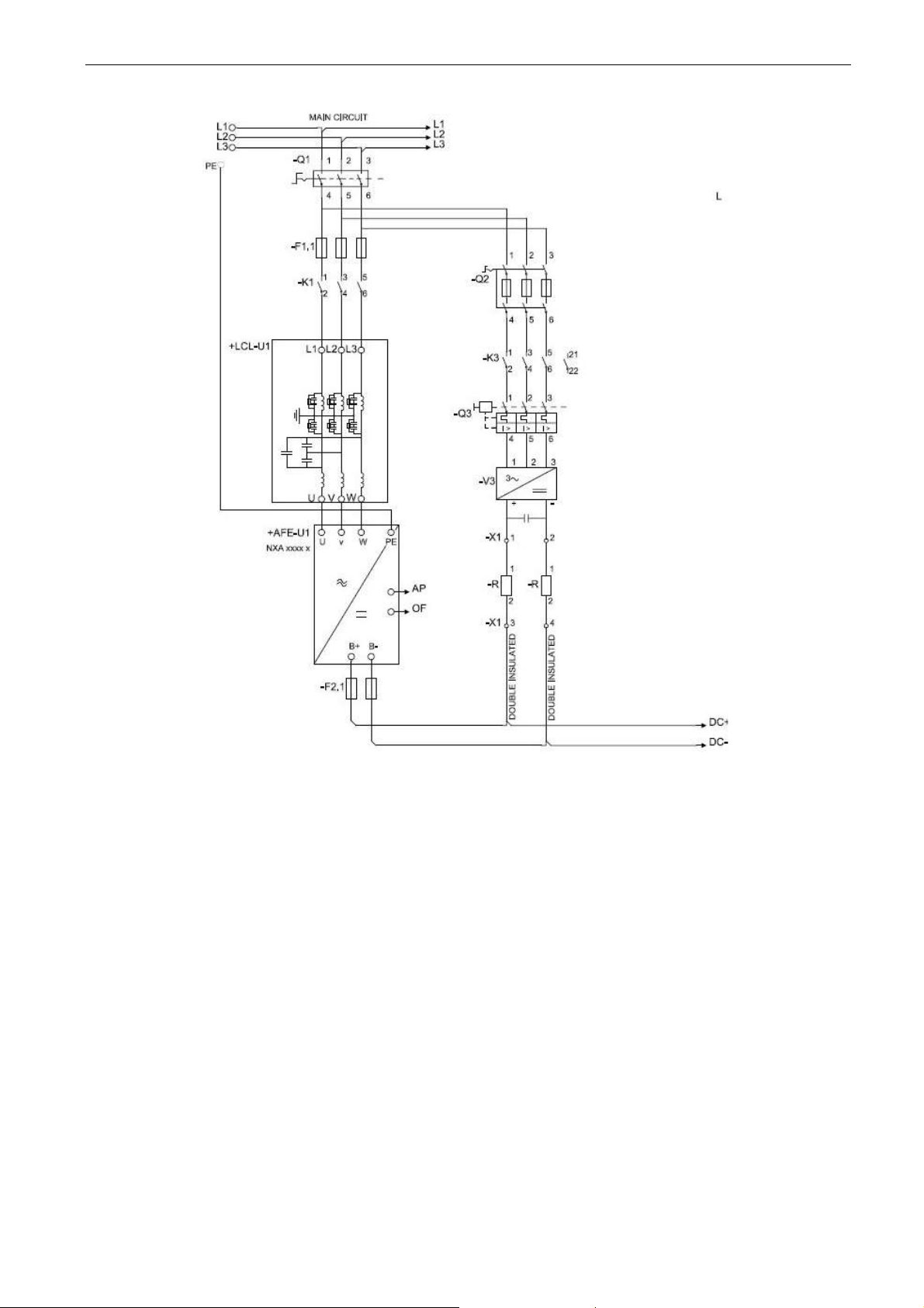
The Grid Converter is utilised by using AFE hardware with special software. An external LC(L)-filter
and charging circuit is needed. This unit is selected when low harmonics are required. The principle
connection of AFE drive has been described in Figure 5.
The external 24 Vdc is recommended for control board(s). It enables the setting of parameters even
when the power unit itself is not powered. This is important also when software updates are made.
Some default I/O configuration of the application can cause unexpected DO operation. When the
control board is powered, the drive can give information from the status of the system if, for example,
the drive I/O is used for an overall system monitoring.
The external 24 Vdc is required for the drives in cases where the start command starts the control
board-controlled precharging operation.
2.1 Quick start instructions
1. Connect the unit according to the Figure 5.
2. Power up the control unit with 24 Vdc.
3. Set the basic parameters (G2.1)
4. Check that the digital input parameters (G2.4.2) have been set according to the connections.
5. Change the control place according to the system requirements.
6. Charge the unit.
2.2 In case of parallel AFE:
1. Set P2.1.5 Parallel AFE to Yes. This will also set DC Drooping to 3.00% (Default).
Page 14
14 · VACON® arfiff03 Grid Converter
Local contacts: http://drives.danfoss.com/danfoss-drives/local-contacts/
2
Classified as Public
Figure 5. Connection
Page 15

arfiff03 Grid Converter VACON® · 15
Local contacts: http://drives.danfoss.com/danfoss-drives/local-contacts/
2
Classified as Public
2.3 Pre-Charging of DC
This AFE application has its own charging control, P2.5.1.13 DC Charge (24 Vdc required for control
board) and charging protection in case the external charging cannot get DC voltage to required level
within set time P2.9.1.6 Charge Max Time (provided that the DC Voltage reaches the under voltage
fault level).
The charging function is activated when P2.5.1.13 DC Charge is A.1 or higher. When the control
place is IO, Keypad or NCDrive, charging is started from the start command.
Charging is not started if:
- Drive is in fault state.
- P2.4.2.26 Enable CB Close is FALSE
- P2.4.2.8 Run Enable is FALSE
- P2.4.2.19 Quick Stop is FALSE
Charging is also stopped if above conditions occur during charging or if the start command is
removed.
For fieldbus control, charging is started with B0 of FB Control Word on the supporting FB profiles.
Charging is also stopped if B0 goes low. Also MCB is opened if already closed.
DC Charge (F80) is given if 85 % of DC Nominal is not reached within P2.9.1.6 Charge Max Time
and charging is stopped.
DC Charging is stopped when the drive receives feedback from P2.4.2.4 MCB Feedback.
NOTE! Use suitably sized DC Charging resistor. To select the correct size, check Pulse loadability
for time duration set in for Max Charge Time parameter.
Page 16

16 · VACON® arfiff03 Grid Converter
Local contacts: http://drives.danfoss.com/danfoss-drives/local-contacts/
2
Classified as Public
2.4 Main circuit breaker control (MCB)
The Grid Converter application controls the circuit breaker of the system with the relay output RO2.
When the DC bus is charged, the MCB will be closed. The status of the MCB is monitored via a
digital input. The digital input used for monitoring is selected with parameter P2.3.1.3. Faults can be
set to open the MCB by selecting a response to a fault to be 3=Fault, DC OFF.
An external charging circuit is necessary to charge the DC bus but drive can control this circuit if 24
Vdc is provided for the control board.
Closing limit is 85% of the nominal DC Voltage.
Opening limit is 75% of the nominal DC Voltage.
Nominal DC Voltage = Grid Nom Voltage (P2.1.1) * 1.35.
Over Current (F1), Hardware IGBT (F31) and Software IGBT (F41) faults will open MCB immediately
to protect the drive.
NOTE! The MCB feedback is necessary for the correct operation of the Grid Converter application.
NOTE! Only the drive controls its own MCB. If additional interlocks or opening commands are
needed, these commands must go through the drive.
NOTE! UPS may be needed during short circuit situation to keep MCB closed if control voltage is
taken from the grid where the short circuit occurs.
NOTE! Missing feedback signal prevent drive going to ready state. MCB Feedback can be monitored
from Status Word B10.
NOTE! If feedback is not used there will be three second forced delay on internally generated MCB
feedback signal. MCB Feedback can be monitored from Status Word B10.
Page 17

arfiff03 Grid Converter VACON® · 17
Local contacts: http://drives.danfoss.com/danfoss-drives/local-contacts/
2
Classified as Public
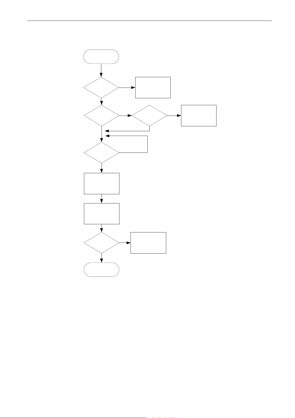
2.5 Start Sequence
Ready to switch
on
Charge
DC-Link
DC-Link
> 85 %
NO
Close Main
Contactor
YES
Main Contactor
Closed
YES
NO
MCC Fault
Fault
Reset
Run Enable
Ready To Run
NO
Start Signal
YES
NO
Synchronize with
mains
Synch OK
NO
YES
Line Synch Fault
F10
Running
Start
Figure 6. AFE start sequence
Page 18
18 · VACON® arfiff03 Grid Converter
Local contacts: http://drives.danfoss.com/danfoss-drives/local-contacts/
2
Classified as Public
2.6 Stop sequence
Modulating
MCB Closed
No
F64 A4
Open MCB
No
Yes
Yes
Stop Modulation
(If Run State)
Open MCB
Stop Request MCB Closed
No
F64 A2
(If DC > 85 %)
(Delayed)
Yes
MCB Closed
No
Yes
F64 A3
(Delayed)
End
Figure 7. Stop sequence
Page 19

arfiff03 Grid Converter VACON® · 19
Local contacts: http://drives.danfoss.com/danfoss-drives/local-contacts/
2
Classified as Public
2.7 afe mode; Start Stop timing diagram
DC Voltage
Charge Control
MCB Feedback
MCB Close Control
MCB Close level
Stable DC
Ready
IO Start
Run
FB CW.B00
Control in
FB Control
FB CW.B03
Contro in
IO Control
P. Start Delay
IO MCB Open
Command
Above example when “Standard” state machine is used. With “Basic” state machine operation
is like in IO Control.
Page 20

20 · VACON® arfiff03 Grid Converter
Local contacts: http://drives.danfoss.com/danfoss-drives/local-contacts/
2
Classified as Public
2.8 Operation principle: Droop Speed Control Mode
When the power demand increases, all generators on the grid allow frequency to droop. This will
balance the load between all the generators on the grid. Then the power management system gives
all generators a command to increase frequency so that the grid frequency is maintained at its
nominal value.
When the load is reducing on the grid, the frequency of the generators will increase, and the power
management system gives a command to decrease frequency.
+1%
+2%
+3%
+4%
-1%
-2%
-3%
-4%
50,5 Hz
51,0 Hz
51,5 Hz
52,0 Hz
48,0 Hz
48,5 Hz
49,0 Hz
49,5 Hz
50,0 Hz
Loading
Un-loading
Drooping
Freq. Change
25% 50% 75% 100%
Related
Load
Figure 8.
2.9 Operation principle: Isochronous Speed Control Mode
In the isochronous speed control mode, the Micro Grid frequency reference is kept the same as the
grid frequency with help of OPT-D7. This will keep power at zero regardless of grid frequency. While
drive operates in drooping mode, the actual power is controlled by base current reference. This
reference needs to be controller by power management system (PMS) that will handle power sharing
between different machines on the grid.
Page 21

arfiff03 Grid Converter VACON® · 21
Local contacts: http://drives.danfoss.com/danfoss-drives/local-contacts/
2
Classified as Public
2.10 Voltage compensation
Grid Converter system will have voltage losses. Depending on the system, the losses may be more
than 50 Vac when operating close to Grid Converter nominal currents with low power factor between
points U3 and U5. This voltage loss needs to be compensated so that the grid voltage stays at
nominal. This also sets requirements for the needed DC link voltage.
Q1
T2
U4
U3
U5
UDCU2
=
~
=
~
Filter
Filter
SG
U1
Q2
U4 = Transf. GC Side
U5 = Transf. Grid Side
D7
T1
S1
MCB Control
Utility Grid
50 Hz
60 Hz
Figure 9. Voltage compensation
The normal operation voltage range in a land-based grid is usually between 80% and 115% of the
grid nominal voltage.
The voltage losses compensation is handled separately for Active power (kW) and Reactive power
(kVar), the latter being more significant. The Active power voltage losses are compensated with
Inductor Losses parameter (P2.2.6.6) and Reactive power voltage losses are compensated with
Inductor Size parameter (P2.2.6.5).
Uncompensated system may result in unnecessary reactive power circulation in a grid between the
different power sources and wrong grid voltage.
OPT-D7 can be used to compensate the voltage losses (closed loop voltage compensation) but it is
recommended to do an open loop voltage compensation tuning in case of OPT-D7 failure. When the
OPT-D7 measurements exceed the set limit values, the voltage compensation falls back to open
loop control.
Inductor Size and Losses affect
Grid Nom. Voltage: 400 Vac, Reactive Current: 30%, Active Current 50%, Inductor
Size: 15%, Inductor Losses: 15%, Voltage Correction: 0 Vac.
Reactive Increase: 400 Vac×30%×15%=18 Vac
Active Increase: 400 VacIncrease:or Losses: 15% 400 Vac×50%×15%×15%=4.5 Vac
Total increase: 18 Vac+4.5 Vac =22.5 Vac
See also document: Voltage Compensation Vxxx.pdf.
Page 22

22 · VACON® arfiff03 Grid Converter
Local contacts: http://drives.danfoss.com/danfoss-drives/local-contacts/
2
Classified as Public
2.11 OPT-D7
OPTD7 is an AC sinusoidal voltage measurement board. Using this board, the drive measures the
line voltage, the frequency and the voltage angle information.
The drive can compare this information with its output voltage angle when it runs. This feature can
be used to make synchronisations to a grid that is measured. For example, for line synchronisation
purposes you can use APFIFF44 LineSynch II Application. That will work as a smooth starter.
In Grid Converter application this can be used:
- To synchronise to existing external grid while the drive is running to enable bumpless transfer
from a generator operation to a shore powered operation in a ship.
- To control the grid voltage (Voltage losses compensation).
- To enable a zero power connection to an existing grid.
- To help in the commissioning of drive active power and reactive power voltage losses
compensation when the actual grid voltage is visible in NCDrive.
The OPT-D7 board is delivered with the transformer which is suitable for a voltage range up to 690
Vac. The transformer cannot be used with a pulse width modulated (PWM) voltage input.
It is possible to use a customised transformer when the input voltage to be measured is not within
the OPT-D7 transformer voltage range. The transformation ratio parameter can be adjusted
according to the transformer primary to secondary ratio. See details in the OPT-D7 user manual.
Synchronisation to the grid can be made without the OPT-D7 when the drive operates in the AFE or
the Micro Grid mode. This requires that the output terminals of the drive are connected to the
existing grid when the drive is in the STOP state. When a start command has been given in AFE or
Micro Grid mode, the drive will make standard AFE synchronisation. Depending on the operation
mode, the drive will start to keep constant DC voltage (AFE) or start to share power based on grid
frequency (Micro Grid). Using OPT-D7 for synchronisation will make the start of the drive smoother.
If the drive does not detect an existing line voltage or frequency in Micro Grid mode, the output
voltage is raised defined time (VoltageRiseTime). In the Island mode, the detection of the grid is not
made and the voltage is raised from zero in the set time (VoltageRiseTime).
NOTE: The OPT-D7 board (in slot C) is mandatory for the Grid Converter unit.
Page 23

arfiff03 Grid Converter VACON® · 23
Local contacts: http://drives.danfoss.com/danfoss-drives/local-contacts/
2
Classified as Public
2.12 Master Follower
2.12.1 General
In master follower modes master is sending control word and DC Voltage reference to follower
drives. Follower drives send a status word to master including some command see details from
monitoring values description.
Start command is synchronized
Master sends run request to followers when all drives indicates that MCB is closed.
o Status is monitored even if follower do not have own MCB or status from the MCB.
If any of the drive goes state where MCB is needed to open all drives will open the MCB.
Control signals to follower drives
o DC voltage reference, can be selected in follower drive if used master or own reference.
2.12.2 Grid Converter Standard master follower In standard master follower mode modulation is not synchronized in any way through system bus
communication. This mode can be used when all the units can work independently but e.g. start and
DC-Link voltage reference is only wanted to give master drive and only four units are needed for
parallel operation.
3-LCL-filters are needed to use
Up to 4 parallel units.
2.12.3 Grid Converter DriveSynch In DriveSynch master follower modulation is synchronized between the drives, basically all follower
will do exactly what master will do.
3-pole LC-filters or standard sine-filters can be used instead of LCL-filters when common point
is connected to transformer.
Up to 4 parallel units.
2.12.4 Grid Converter D2-Synch In D2-Synch each unit operate independently only modulation switching is synchronised to eliminate
rotating currents.
Page 24
24 · VACON® arfiff03 Grid Converter
Local contacts: http://drives.danfoss.com/danfoss-drives/local-contacts/
2
Classified as Public
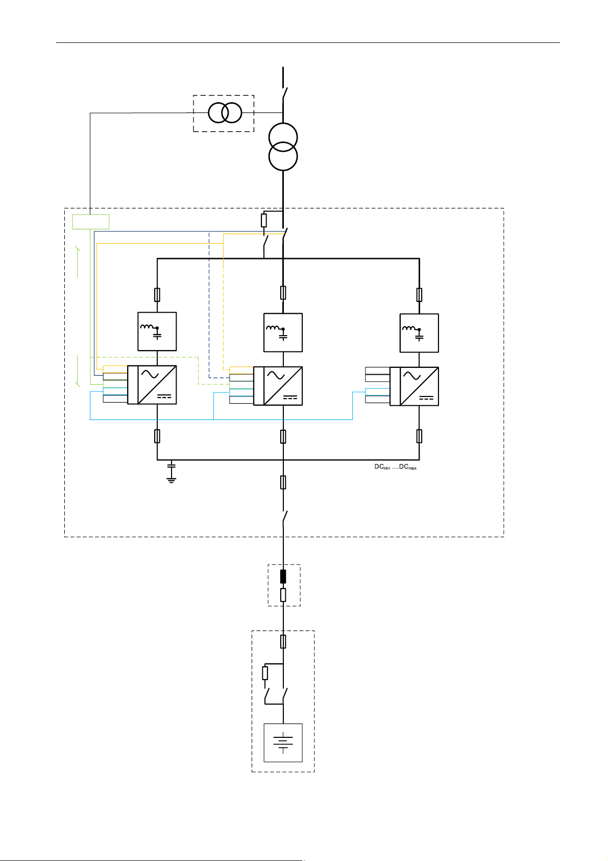
OPT-D7
OPT-A2
OPT-??
OPT-D2
OPT-A1
OPT-D7
Transformer
Master
Follower
Backup Master
Follower
OPT-D7
OPT-A2
OPT-??
OPT-D2
OPT-A1
OPT-A2
OPT-??
OPT-D2
OPT-A1
Optical
Fibre
MCB
Feedback
Optional
NOTE:
1. Breaker to be equipped with optional precharging of Sine-Filter
capacitors
(Can be parallel smaller breaker with resistors for example). Precharge
will precharge DC-link capacitors as well.
2. High Frequency (HF) capacitors to be installed to limit Common Mode
Voltage (CMV) for the batteries.
3. Breaker to be equipped with precharging of DC-Link capacitors
(Can be parallel smaller breaker with resistors for example)
4. Verify that the battery side fuse selection is according to
discrimination.
See note 1.
Drive
Supply
L
R
Cable
See note 2.
N
X
P
N
X
P
N
X
P
Limit 11V
-cable length <1m for
better EMC performance
Applicable if MV
400-690 / MV
DC-Link Fuses
According to
Discrimination Study
See note 3.
See note 4.
One option is to have many
parallel fuses (not drawn
here). Each fuse protects
one battery string and
cable.
Optional
Optional
MCB
Control
Optional
Page 25

arfiff03 Grid Converter VACON® · 25
Local contacts: http://drives.danfoss.com/danfoss-drives/local-contacts/
3
Classified as Public
3. Control I/O
3.1 Slot A and Slot B terminals
Table 1. Minimum recommended I/O configuration.
OPT-A1
Terminal
Signal
Description
1
+10V
ref
Reference voltage output
Voltage for potentiometer, etc.
2
AI1+
Analogue input 1.
Range 0-10V, Ri = 200
Range 0-20 mA Ri = 250
Input range selected by jumpers.
Default range: Voltage 0 – 10 V
3
AI1-
I/O Ground
Ground for reference and controls
4
AI2+
Analogue input 2.
Range 0-10V, Ri = 200
Range 0-20 mA Ri = 250
Input range selected by jumpers.
Default range: Current 0 – 20 mA
5
AI2-
6
+24V
Control voltage output
Voltage for switches, etc. max 0.1 A
7
GND
I/O ground
Ground for reference and controls
8
DIN1
Programmable G2.2.1
9
DIN2
Programmable G2.2.1
10
DIN3
Programmable G2.2.1
11
CMA
Common for DIN 1– DIN 3
Connect to GND or +24V
12
+24V
Control voltage output
Voltage for switches (see #6)
13
GND
I/O ground
Ground for reference and controls
14
DIN4
MCB Feedback
Programmable G2.2.1
0 = MCB open
1 = MCB closed
15
DIN5
Quick Stop
Programmable G2.2.1
0 = Quick Stop Active
1 = No Quick Stop
16
DIN6
Programmable G2.2.1
17
CMB
Common for DIN4– DIN6
Connect to GND or +24V
18
AO1+
Analogue output 1
Programmable
Range 0– 20 mA/RL, max. 500
19
AO1-
20
DO1
Digital output
READY
Programmable P2.3.1.1
Open collector, I50mA, U48 VDC
OPT-A2
21
RO1
Relay output 1
Programmable P2.3.1.2
Switching capacity
24 VDC / 8 A
22
RO1
23
RO1
250 VAC / 8A
125 VDC / 0.4 A
24
RO2
Relay output 2
MCB control
This RO is not programmable.
Fixed for MCB Control (Close)
25
RO2
26
RO2
3.2 Terminal To Function (TTF)
The programming principle of the input and output signals in the Grid Converter Application is
different compared to the conventional method used in other VACON® NX applications.
In the conventional programming method, Function to Terminal Programming Method (FTT), you
have a fixed input or output that you define a certain function for. The applications mentioned above,
however, use the Terminal to Function Programming method (TTF) in which the programming
pro¬cess is carried out the other way round: Functions appear as parameters which the operator
defines a certain input/output for.
Page 26

26 · VACON® arfiff03 Grid Converter
Local contacts: http://drives.danfoss.com/danfoss-drives/local-contacts/
3
Classified as Public
3.3 Defining inputs and outputs
Connecting a certain input or output with a certain function (parameter) is done by giving the
parameter an appropriate value. The value is formed of the Board slot on the VACON® NX control
board (see VACON® NX User Manual) and the respective signal number, see below.
Function name
Slot Terminal number
Terminal type
Example: You want to connect the digital output function Reference fault/warning (parameter
2.3.3.7) to the digital output DO1 on the basic board NXOPTA1 (see VACON® NX User Manual).
First find the parameter 2.3.3.7 on the keypad. Press the Menu button right once to enter the edit
mode. On the value line, you will see the terminal type on the left (DigIN, DigOUT, An.IN, An.OUT)
and on the right, the present input/output the function is connected to (B.3, A.2 etc.), or if not
connected, a value (0.#).
When the value is blinking, hold down the Browser button up or down to find the desired board slot
and signal number. The program will scroll the board slots starting from 0 and proceeding from A to
E and the I/O selection from 1 to 10.
Once you have set the desired value, press the Enter button once to confirm the change.
READY
I/Oterm
DigOUT:B.1
AI Ref Faul/Warn
READY
I/Oterm
DigOUT:0.0
READY
I/Oterm
DigOUT:0.0
READY
I/Oterm
DigOUT:B.1
enter
AI Ref Faul/Warn AI Ref Faul/Warn AI Ref Faul/Warn
Page 27

arfiff03 Grid Converter VACON® · 27
Local contacts: http://drives.danfoss.com/danfoss-drives/local-contacts/
3
Classified as Public
3.4 Defining a terminal in NCDrive
If you use the VACON® NCDrive Programming Tool for parametrizing you will have to establish the
connec¬tion between the function and input/output in the same way as with the control panel. Just
pick the address code from the drop-down menu in the Value column (see the Figure below).
Figure 3 1. Screenshot of NCDrive programming tool; Entering the address code
Be ABSOLUTELY sure not to connect two functions to one and
same output in order to avoid function overruns and to ensure
flawless operation.
!
WARNING
Note: The inputs, unlike the outputs, cannot be changed in RUN state.
Page 28

28 · VACON® arfiff03 Grid Converter
Local contacts: http://drives.danfoss.com/danfoss-drives/local-contacts/
4
Classified as Public
4. Monitoring signals
The menu M1 (Monitoring) has all the monitoring values. Values are only for monitoring and cannot
be altered on the control panel.
4.1 Monitoring value tables
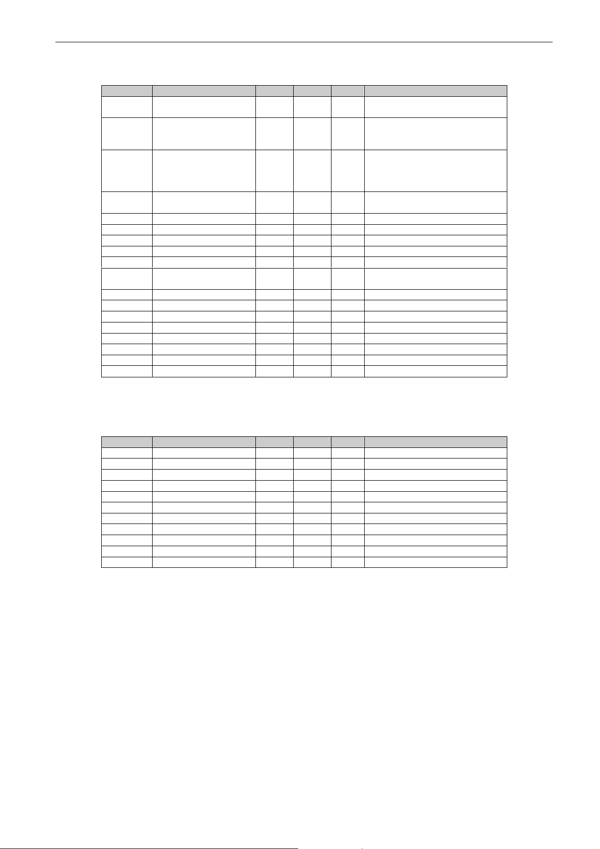
4.1.1 Monitoring values 1
Code
Parameter
Unit
Form.
ID
Description
V1.1.1
DC-Link Voltage
V # 1108
Measured DC Link voltage in volts,
filtered.
V1.1.2
DC Voltage Ref.
%
#,##
1200
Used DC voltage reference by the
regenerative unit in % of Nominal DC
voltage.
Nominal DC voltage = 1.35 * supply
voltage
V1.1.3
DC Voltage Act.
%
#,##
7
Same scaling as DC Voltage Ref.
V1.1.4
Total Current
A
Varies
1104
Filtered current
V1.1.5
Active Current
%
#,#
1125
> 0 power from AC side to DC side
< 0 power from DC side to AC side
V1.1.6
Reactive Current
%
#,#
1157
V1.1.7
Power kW
kW
Varies
1508
> 0 power from AC side to DC side
< 0 power from DC side to AC side
V1.1.8
Power %
%
#,#
5
> 0 power from AC side to DC side
< 0 power from DC side to AC side
V1.1.9
Status Word
# 43 V1.1.10
Supply Frequency
Hz
#,##
1
Drive output frequency
V1.1.11
Supply Voltage
V
#,#
1107
Drive output voltage
V1.1.12
Line Frequency D7
Hz
#,##
1654
Measured line frequency
V1.1.13
Line Voltage D7
V # 1650
Measured line voltage
V1.1.14
AC Voltage Reference
V # 1556
Used AC Voltage Reference
V1.1.15
DC Ref Max Lim
%
#,##
1606
Internal limit for DC Voltage Ref.
Page 29
arfiff03 Grid Converter VACON® · 29
Local contacts: http://drives.danfoss.com/danfoss-drives/local-contacts/
4
Classified as Public
4.1.2 Monitoring values 2
Code
Parameter
Unit
Form.
ID
Description
V1.2.1
DC Voltage
V # 44
Measured DC Link voltage in
volts, unfiltered.
V1.2.2
Operation Mode
# 1615
0 = AFE
1 = Island
2 = Micro Grid
V1.2.3
Used Current Ref
%
#,#
1704
Used current reference is
negated to parameter value.
Made to compare values in
NCDrive easier to Active current
V1.2.4
D7 Synch. Error
# 1659
Synchronisation error to external
grid
V1.2.5
Cos Phi Actual
#,###
1706 V1.2.6
Unit Temperature
°C # 1109 V1.2.7
Freq. Reference
Hz
#,#
1752
Used line frequency reference
V1.2.8
Current
A
Varies
1113
Unfiltered current
V1.2.9
Operation Hours
h
#,##
1856
V1.2.10
Reactive Current
Reference
%
#,#
1389
V1.2.11
Grid State
# 1882 V1.2.12
Mindex
%
#,#
1858
Modulation Index
V1.2.13
Phase U Current
A
Varies
39
rms, 1 second linear filtering
V1.2.14
Phase V Current
A
Varies
40
rms, 1 second linear filtering
V1.2.15
Phase W Current
A
Varies
41
rms, 1 second linear filtering
V1.2.16
DC-Link Current
A
Varies
72 V1.2.17
DC-Link ActCurr
%
#,#
1158
V1.2.18
Crest Factor
#,###
1101
4.1.3 Fieldbus monitoring values
Code
Parameter
Unit
Form.
ID
Description
V1.3.1
FB Control Word
# 1160
Control word from fieldbus
V1.3.2
FB Status Word
# 68
Status word to fieldbus
V1.3.3
Fault Word 1
# 1172
V1.3.4
Fault Word 2
# 1173
V1.3.5
Warning Word 1
# 1174 V1.3.6
FB Micro Grid CW1
# 1700
Control for Micro Grid operations
V1.3.7
FB Micro Grid SW1
# 1701
Status of Micro Grid operations
V1.3.8
Last Active Warning
# 74
V1.3.9
Last Active Fault
# 37
V1.3.10
MC Status
# 64 V1.3.11
FB Analogue Out
#,##
48
Page 30

30 · VACON® arfiff03 Grid Converter
Local contacts: http://drives.danfoss.com/danfoss-drives/local-contacts/
4
Classified as Public
4.1.4 I/O monitoring values
Code
Parameter
Unit
Form.
ID
Description
V1.4.1
DIN1, DIN2, DIN3
# 15 V1.4.2
DIN4, DIN5, DIN6
# 16 V1.4.3
DIN Status 1
# 56 V1.4.4
DIN Status 2
# 57
V1.4.5
Analogue Input 1
%
#,##
13 V1.4.6
Analogue Input 2
%
#,##
14
V1.4.7
Analogue input 3
%
#,##
27
AI3, unfiltered.
V1.4.8
Analogue input 4
%
#,##
28
AI4, unfiltered.
V1.4.9
Analogue Out 1
%
#,##
26
V1.4.10
Analogue Out 2
%
#,##
50
AO2
V1.4.11
Analogue Out 3
%
#,##
51
AO3
V1.4.12
PT100 Temp. 1
°C
#,#
50
V1.4.13
PT100 Temp. 2
°C
#,#
51
V1.4.14
PT100 Temp. 3
°C
#,#
52 V1.4.15
PT100 Temp. 4
°C
#,#
69 V1.4.16
PT100 Temp. 5
°C
#,#
70 V1.4.17
PT100 Temp. 6
°C
#,#
71
4.1.5 Master/Follower
Code
Parameter
Unit
Form.
ID
Description
V1.5.1
SB SystemStatus
# 1819 V1.5.2
Master CW
# 93 Code
Parameter
Unit ID
Description
V1.5.3.1
Current D1
A
Varies
1820
V1.5.3.2
Current D2
A
Varies
1821
V1.5.3.3
Current D3
A
Varies
1822
V1.5.3.4
Current D4
A
Varies
1823 Code
Parameter
Unit ID
Description
V1.5.4.1
Status Word D1
# 1828
V1.5.4.2
Status Word D2
# 1829
V1.5.4.3
Status Word D3
# 1830
V1.5.4.4
Status Word D4
# 1831
4.1.6 Licence key activation
Code
Parameter
Unit
Form.
ID
Description
V1.6.1
Serial Number Key
# 1997
Give this number to the
technical support of the
manufacturer in case of licence
key problems.
V1.6.2
Licence Status
# 1996
4.1.7 Line Monitoring
Code
Parameter
Unit
Form.
ID
Description
V1.7.1
Line Voltage D7
Hz
#,##
1654
Measured line voltage
V1.7.2
Line Frequency D7
V # 1650
Measured line frequency
V1.7.3
Line Voltage THD
%
#,##
1670
Line voltage total harmonic
distortio
V1.7.4
Line Voltage HF RMS
V
#,#
1671
RMS of high frequency
components
Page 31

arfiff03 Grid Converter VACON® · 31
Local contacts: http://drives.danfoss.com/danfoss-drives/local-contacts/
4
Classified as Public
4.1.8 Active Limits
Code
Parameter
Unit
Form.
ID
Description
V1.8.1
Current Limit
A
Varies
1954
4.1.9 PI Power Controller
Code
Parameter
Unit
Form.
ID
Description
V1.8.1
PID Reference
#,#
20
V1.8.2
PID Actual Value
#,#
21 V1.8.3
PID Output
#,##
23
Page 32

32 · VACON® arfiff03 Grid Converter
Local contacts: http://drives.danfoss.com/danfoss-drives/local-contacts/
4
Classified as Public
4.2 Description of monitoring values
4.2.1 Monitoring 1 values
V1.1.1 DC-Link Voltage V ID1108
The measured DC voltage, filtered.
V1.1.2 DC Voltage Ref. % ID1200
The DC voltage reference. Percentage value of P: System Nom DC. If System Nom DC
is not given this is scaled to P: Grid Nom Voltage.
V1.1.3 DC Voltage Act. % ID7
Actual DC Voltage. Percentage value of P: System Nom DC. If System Nom DC is not
given this is scaled to P: Grid Nom Voltage.
V1.1.4 Total Current A ID 1113
The filtered current of the drive.
V1.1.5 Active Current % ID 1125
The active current in % of System Rated Current.
Active Current > 0: Current flow from AC-Side to Drive DC-Link.
Active Current < 0: Current flow from Drive DC-Link to AC-Side.
V1.1.6 Reactive Current % ID 1157
The reactive current of the regenerative drive in % of System Rated Current.
V1.1.7 Power kW kW ID 1508
The output power of the drive in kW.
A negative value means that the current is flowing to AC side from DC side.
V1.1.8 Power % % ID 5
The output power of the drive in %. 100,0 % equals 100,0 % Active Current and 100.0 %
Supply Voltage.
Power > 0: Current flow from AC-Side to Drive DC-Link.
Power < 0: Current flow from Drive DC-Link to AC-Side.
Page 33

arfiff03 Grid Converter VACON® · 33
Local contacts: http://drives.danfoss.com/danfoss-drives/local-contacts/
4
Classified as Public
V1.1.9 Status Word (Application) ID 43
The Application Status Word combines different statuses of the drive to one data word.
Status Word (Application) ID43
FALSE
TRUE
b0
DO Charge FALSE
DO Charge TRUE
b1
Not in Ready state
Ready
b2
Not Running
Running
b3
No Fault
Fault
b4
No Start Request
Start Request active
b5
Quick stop active
Quick stop not active
b6
Run Disabled
Run Enable
b7
No Warning
Warning
b8
Internal Charge Open
Charging Switch closed (internal)
b9
MCB Controlled open
MCB Controlled Closed
b10
MCB Feedback FALSE
MCB Feedback TRUE
b11
Short Circuit Mode Not Active
Short Circuit Mode Active
b12
No Run Request
Run Request
b13
Not at current limit
At Current Limit
b14
AFE Mode Active
Island Mode Active
b15
uGrid Mode Active
V1.1.10 Supply Frequency Hz ID 1
The drive output frequency. Updated in the STOP state when Regen Option B9 is
activated.
V1.1.11 Supply Voltage V ID 1107
The drive output voltage.
V1.1.12 Line Frequency D7 Hz ID 1654
The measured line voltage frequency when using the OPT-D7 option board in slot C.
When the OPT-D7 board is not used, it is possible to use Analogue Input 3 and 4 ID
write function to give the grid the Line Frequency and Line Voltage. This enables use of
grid PI voltage controller without the OPT-D7 board. Note that both line frequency and
line voltages needs to be given. By activating Control Options 2 B2 these analogue
inputs can be used also to grid protection.
V1.1.13 Line Voltage D7 V ID 1650
The measured line voltage rms value when using the OPT-D7 option board in slot C.
When the OPT-D7 board is not used, it is possible to use Analogue Input 3 and 4 ID
write function to give the grid the Line Frequency and Line Voltage. This enables use of
grid PI voltage controller without the OPT-D7 board. Note that both line frequency and
line voltages needs to be given. By activating Control Options 2 B2 these analogue
inputs can be used also to grid protection.
Page 34

34 · VACON® arfiff03 Grid Converter
Local contacts: http://drives.danfoss.com/danfoss-drives/local-contacts/
4
Classified as Public
V1.1.14 AC Voltage Reference V ID 1556
The used AC voltage reference.
V1.1.15 DC Voltage Max Limit % ID 1606
The drive will limit the DC reference to inside drive specification but allows higher
reference if lower supply voltage. This shows the final limit of the DC reference.
Page 35

arfiff03 Grid Converter VACON® · 35
Local contacts: http://drives.danfoss.com/danfoss-drives/local-contacts/
4
Classified as Public
4.2.2 Monitoring 2 values
V1.2.1 DC Voltage V ID 44
The measured DC voltage, unfiltered.
V1.2.2 Operation Mode ID 1615
The active Grid Converter operation mode.
0 = AFE operation
1 = Island operation
2 = Micro Grid Operation
V1.2.3 Used Current Ref % ID 1704
The used current reference. The value is negative to the set parameter to make the
monitoring easier in NCDrive since Active Current shows negative value when power
direction is from DC-Link to AC Line When the Current Reference mode is not used this
will show Active Current.
V1.2.4 D7 Synch. Error ID 1659
An error on voltage angles between the drive and the measurement taken by OPT-D7.
-3072...+3071 = -180...180 degrees.
If the value is not near to zero when running in AFE mode, the phase order may be
wrong even if the OPT-D7 frequency is correct (Error about 2047 = 120 degree). If the
measurement is after the Dyn11 transformer, the error is usually about 512 (30.0
Degrees).
V1.2.5 CosPhiActual ID 1706
The calculated Cos Phi.
V1.2.6 Unit Temperature °C ID 1109
The heatsink temperature of the drive.
V1.2.7 Frequency Reference Hz ID1752
The used frequency reference. In AFE mode, the frequency reference is determined
internally when the synchronisation is made. In Island and Micro Grid mode, the
reference is used for a static power supply, and a power drooping in Micro Grid mode.
V1.2.8 Current A ID 1113
The unfiltered current of the drive.
Page 36

36 · VACON® arfiff03 Grid Converter
Local contacts: http://drives.danfoss.com/danfoss-drives/local-contacts/
4
Classified as Public
V1.2.9 Operation Hours h ID 1856
This shows operation hours of the drive. G2.7 Operation Time is used to enter old value
if the software is updated.
V1.2.10 Reactive Current Reference % ID 1389
The final reactive current reference.
V1.2.11 Grid State ID 1882
The Status Word for the grid.
Grid State ID1882
b0
Supply frequency or frequency from OPT-D7 below fault limit
b1
Supply frequency or frequency from OPT-D7 below warning limit
b2
Supply frequency or frequency from OPT-D7 above warning limit
b3
Supply frequency or frequency from OPT-D7 above fault limit
b4
Voltage from OPT-D7 below fault limit
b5
Voltage from OPT-D7 below warning limit
b6
Voltage from OPT-D7 above warning limit
b7
Voltage from OPT-D7 above fault limit
b8
Supply voltage below fault limit
b9
Supply voltage below warning limit
b10
Supply voltage above warning limit
b11
Supply voltage above fault limit
b12
b13
b14
b15
V1.2.12 Mindex % ID 1874
This value can be used to recognize low Dc-Link voltage when operating in island and
uGrid modes. If the value is above 90%, the drive is in limits to make correct voltage to
AC side.
V1.2.13 Phase U Current A ID39
V1.2.14 Phase V Current A ID40
V1.2.15 Phase W Current A ID41
Phase Currents rms value. 1 second linear filtering.
V1.2.16 DC-Link Current A ID72
Calculated DC-Link Current in Amps.
V1.2.17 DC-Link ActCurr % #,# ID1158
Calculated DC-Link Current in %.
Page 37

arfiff03 Grid Converter VACON® · 37
Local contacts: http://drives.danfoss.com/danfoss-drives/local-contacts/
4
Classified as Public
V1.2.18 Crest Factor #,### ID1101
Crest factor of the current.
4.2.3 Fieldbus monitoring values
V1.3.1 FB Control Word ID 1160
The control word from fieldbus. The table below is for “2 / Vacon AFE 1” Selection
(P2.10.19) in bypass operation for such fieldbus board that natively supports this or can
be parameterised to bypass mode. See other profile selections from chapter Status and
Control Word.
FB Control Word ID1160
Signal
Comment
b0
DC Charge
0 = Open MCB.
1 = Close DC charge contactor, MCB closed automatically.
b1
b2
b3
Start
0 = Stop Command
1 = Start Command
b4
b5
b6
b7
Reset
0>1 Reset fault.
b8
b9
b10
Fieldbus
Control
0 = No control from fieldbus
1 = Control from fieldbus
b11
Watchdog
0>1>0>1…0.5 s square wave clock. This is used to check
data communication between the fieldbus master and the
drive.
b12
FB DIN2
Can be used to control RO or the parameter directly by ID
number. G2.4.1
b13
FB DIN3
Can be used to control RO or the parameter directly by ID
number. G2.4.1
b14
FB DIN4
Can be used to control RO or the parameter directly by ID
number. G2.4.1
b15
Page 38

38 · VACON® arfiff03 Grid Converter
Local contacts: http://drives.danfoss.com/danfoss-drives/local-contacts/
4
Classified as Public
V1.3.2 FB Status Word ID 68
This is referred as GeneralStatusWord in the fieldbus manual. See details in the fieldbus
manual. See details from of FB Status Word from chapter 8.6 FB Status Word.
FB Status Word ID68
Signal
Comment
b0
Ready On
0 = Drive not ready to charge
1 = Drive ready to charge
b1
Ready Run
0 = Drive not ready to run
1 = Drive ready to run and MCB is ON
b2
Running
0 = Drive not running
1 = Drive running with regenerative control ON
b3
Fault
0 = No active fault
1 = Fault is active
b4
Run Enabled
0 = Run Disabled by I/O Commands
1 = Run Enabled by I/O Commands
b5
Quick Stop
0 = Quick Stop Active
1 = Quick Stop Not Active
b6
Switch On Inhibit
0 = CB Control OK
1 = CB Requested open but DC is high
b7
Warning
0 = No warning
1 = Warning active
b8
At Reference
0 = DC Voltage Ref and Act DC Voltage are not same.
1 = DC Voltage Ref and Act DC Voltage are same.
b9
Fieldbus Control
Active
0 = Fieldbus control not active
1 = Fieldbus control active
b10
Above Limit
0 = DC voltage is below the level specified by P2.5.7.4
1 = The DC voltage is above the level specified by
P2.5.7.4
b11
FB_SW_B11
Select bit in G2.10 Fieldbus
b12
FB_SW_B12
Select bit in G2.10 Fieldbus
b13
FB_SW_B13
Select bit in G2.10 Fieldbus
b14
FB_SW_B14
Select bit in G2.10 Fieldbus
b15
Watchdog
Page 39

arfiff03 Grid Converter VACON® · 39
Local contacts: http://drives.danfoss.com/danfoss-drives/local-contacts/
4
Classified as Public
V1.3.3 Fault Word 1 ID 1172
Fault Word 1
Bit
Fault(s)
B0
F1 Over current, F31 IGBT, F41 IGBT
B1
F2 Over Voltage
B2
F9 Under Voltage
B3
F91 Short Circuit
B4
F3 Earth Fault
B5
B6
F14 Unit Over Temperature
B7
F16 Motor Temperature, F29 Thermistor, F56 PT100
B8
F10 Line Synch fault
B9
B10 B11
F52 Keypad or F52 PC communication fault
B12
F53 FieldBus fault
B13
F59 System Bus fault
B14
F54 Slot Communication fault
B15
F50 4mA fault
V1.3.4 Fault Word 2 ID 1173
Fault Word 2
Bit
Fault(s)
B0
F11 Output phase
B1
F80 Charge Fault
B2
B3
B4
B5
B6
F51 External Fault 1 or F84 External Fault 2
B7
B8
B9
F31 IGBT, F41 IGBT
B10
B11
F60 Cooling Monitoring
B12 B13 B14
F64 Main Switch State fault
B15
Page 40

40 · VACON® arfiff03 Grid Converter
Local contacts: http://drives.danfoss.com/danfoss-drives/local-contacts/
4
Classified as Public
V1.3.5 Warning Word 1 ID 1174
Warning Word 1 ID1174
Bit
Warning(s)
B0
W91 Short Circuit
B1 B2
B3
B4
B5
B6
F53 FB Warning Slot D
B7
F67 FB Warning Slot E
B8
F14 Over Temperature
B9
B10 B11 B12
B13
B14 B15
V1.3.6 FB Micro Grid CW1 ID 1700
Control for the Micro Grid operations.
FB Micro Grid CW1 ID1700
Signal
Comment
b0
Start As Island
If B0 & B1 = FALSE operation mode is AFE.
B10 to enable. B11 to change in Run State
b1
Start As Micro Grid
b2
Start synchronisation D7
Synchronization to external grid with OPT-D7
b3
b4
Power Down
Same as P2.2.6.2
b5
Power Up
Same as P2.2.6.3
b6
Reset Hz MotPot
Same as P2.4.2.27
b7
Voltage Down
Same as P2.2.6.7
b8
Voltage Up
Same as P2.2.6.8
b9
Reset Volt MotPot
b10
Enable FB Control Mode
B0 and B1 are controlling Operation Mode
b11
Live Mode Control
B0 and B1, Mode changed in Run State, if B10 = TRUE
b12
P2.10.27 uCW B12
b13
P2.10.28 uCW B12
b14
P2.10.29 uCW B12
b15
P2.10.30 uCW B12
Page 41

arfiff03 Grid Converter VACON® · 41
Local contacts: http://drives.danfoss.com/danfoss-drives/local-contacts/
4
Classified as Public
V1.3.7 FB Micro Grid SW1 ID 1701
Status of the Micro Grid operations.
Micro Grid Status Word
Signal
Comment
b0
Charge Control active
Charging
b1
Internal Charging switch status
b2
MCB control
b3
MCB status
b4
Run Enabled
b5
Drive Ready
b6
AFE mode active
b7
Island mode active
b8
Micro Grid mode active
b9
Run Request active
b10
Drive in run state
b11
Fault Active
b12
SynchronizedToD7
b13
b14
D7 measurements OK
b15
V1.3.8 Warning ID 74
The number of the last active warning.
V1.3.9 Last Active Fault ID 37
The number of the last active fault.
Page 42

42 · VACON® arfiff03 Grid Converter
Local contacts: http://drives.danfoss.com/danfoss-drives/local-contacts/
4
Classified as Public
V1.3.10 MC Status ID 64
For the fieldbuses that do not have their own state machine, this value is sent to fieldbus.
Motor Control Status Word
FALSE
TRUE
b0
Not in Ready state
Ready
b1
Not Running
Running
b2
Direction Clockwise
Counter clockwise
b3
No Fault
Fault
b4
No Warning
Warning
b5 At reference speed
b6 At Zero Speed
b7 Flux Ready
b8 TC Speed Limiter Active
b9
Encoder Direction
Counter clockwise
b10 Under Voltage Fast stop
b11
No DC brake
DC Brake is active
b12
b13 Restart delay active
b14
b15
V1.3.11 FB Analogue Out ID 48
Fieldbus value to control analogue output.
Page 43

arfiff03 Grid Converter VACON® · 43
Local contacts: http://drives.danfoss.com/danfoss-drives/local-contacts/
4
Classified as Public
4.2.4 I/O monitoring values
V1.4.1 DIN1, DIN2, DIN3 ID 15
V1.4.2 DIN4, DIN5, DIN6 ID 16
DIN1/DIN2/DIN3 status
DIN4/DIN5/DIN6 status
b0
DIN3
DIN6
b1
DIN2
DIN5
b2
DIN1
DIN4
V1.4.3 DIN Status 1 ID 56
V1.4.4 DIN Status 2 ID 57
DIN StatusWord 1
DIN StatusWord 2
b0
DIN: A.1
DIN: C.5
b1
DIN: A.2
DIN: C.6
b2
DIN: A.3
DIN: D.1
b3
DIN: A.4
DIN: D.2
b4
DIN: A.5
DIN: D.3
b5
DIN: A.6
DIN: D.4
b6
DIN: B.1
DIN: D.5
b7
DIN: B.2
DIN: D.6
b8
DIN: B.3
DIN: E.1
b9
DIN: B.4
DIN: E.2
b10
DIN: B.5
DIN: E.3
b11
DIN: B.6
DIN: E.4
b12
DIN: C.1
DIN: E.5
b13
DIN: C.2
DIN: E.6
b14
DIN: C.3
b15
DIN: C.4
V1.4.5 Analogue Input 1 % ID 13
V1.4.6 Analogue Input 2 % ID 14
V1.4.7 Analogue input 3 % ID 27
V1.4.8 Analogue Input 4 % ID 28
The unfiltered analogue input level.
0% = 0 mA / 0 V, -100% = -10 V, 100% = 20 mA / 10 V. Monitoring scaling is determined
by the option board parameter. It is possible to adjust this input value from fieldbus when
the input terminal selection is 0.1. This way it is possible to adjust the free analogue input
from fieldbus and have all the analogue input functions available for fieldbus process
data.
V1.4.9 Analogue Out 1 % ID 26
V1.4.10 Analogue Out 2 % ID 50
V1.4.11 Analogue Out 3 % ID 51
Analogue Output value 0% = 0 mA / 0 V, 100% = 20 mA / 10 V
Page 44

44 · VACON® arfiff03 Grid Converter
Local contacts: http://drives.danfoss.com/danfoss-drives/local-contacts/
4
Classified as Public
V1.4.12 PT100 Temp. 1 °C ID 50
V1.4.13 PT100 Temp. 2 °C ID 51
V1.4.14 PT100 Temp. 3 °C ID 52
V1.4.15 PT100 Temp. 4 °C ID 69
V1.4.16 PT100 Temp. 5 °C ID 70
V1.4.17 PT100 Temp. 6 °C ID 71
A separate measurement from two PT100 board. The signal has a 4 s filtering time.
4.2.5 Master Follower
V1.5.1 SB SystemStatus # ID1819
System Bus Status Word ID1819
b0
b1
Drive 1 Ready
b2
Drive 1 Running
b3
Drive 1 Fault
b4
b5
Drive 2 Ready
b6
Drive 2 Running
b7
Drive 2 Fault
b8
b9
Drive 3 Ready
b10
Drive 3 Running
b11
Drive 3 Fault
b12
b13
Drive 4 Ready
b14
Drive 4 Running
b15
Drive 4 Fault
Page 45

arfiff03 Grid Converter VACON® · 45
Local contacts: http://drives.danfoss.com/danfoss-drives/local-contacts/
4
Classified as Public
V1.5.2 Master CW # ID93
Master Control Word ID93
Signal
b0
b1
Modulating
b2
Run Request
b3
Fault Reset
b4
Pre-Start request
b5
WD Pulse
b6
MCB Open Commands
b7
b8
DIN Run Enable
b9
Data Logger trig request
b10
b11
b12
b13
b14
b15
4.2.5.1 Currents
V1.5.3.1 Current D1 A Varies 1820
V1.5.3.2 Current D2 A Varies 1821
V1.5.3.3 Current D3 A Varies 1822
V1.5.3.4 Current D4 A Varies 1823
Page 46

46 · VACON® arfiff03 Grid Converter
Local contacts: http://drives.danfoss.com/danfoss-drives/local-contacts/
4
Classified as Public
4.2.5.2 Statuses
V1.5.4.1 Status Word D1 # 1828
V1.5.4.2 Status Word D2 # 1829
V1.5.4.3 Status Word D3 # 1830
V1.5.4.4 Status Word D4 # 1831
Follower Drive status word
Signal
b0
Data Logger trig request
b1
Ready
b2
Run b3
Fault
b4
b5
b6
b7
b8
MCB Control Status
b9
MCB Closed
b10
MCB Open command
b11
b12
b13
b14
b15
WD Pulse
Page 47

arfiff03 Grid Converter VACON® · 47
Local contacts: http://drives.danfoss.com/danfoss-drives/local-contacts/
4
Classified as Public
4.2.6 Activation status
V1.6.1 Serial Number Key ID 1997
Give this number to the technical support of the manufacturer when there is a problem in
the activation of a function. The drive shows a licence fault.
V1.6.2 Licence Status ID 1996
This value indicates the status of the licence key activation.
0 / No Function
If PLC receives this number from this ID, it is likely that the Grid Converter application is
not loaded on the drive.
1 / No Code
Correct application in the drive, but the licence key has not been given.
2 / Code Given, not possible to verify, no connection to power unit
The licence key has been given, but there is no connection to power unit to verify it.
Charge the DC at least for 20 s.
NOTE! It is possible that the drive gives a licence fault in this state. Power up the power
unit, so that the control board can read the drive serial number.
3 / Code Wrong
The code that was entered is wrong.
4 / Licence Key entered too many times
A wrong licence key has been entered three times. Power down the drive before trying to
enter a new code.
5 / Code Accepted
The correct key has been entered, and all functions of Grid Converter application are
available.
Page 48

48 · VACON® arfiff03 Grid Converter
Local contacts: http://drives.danfoss.com/danfoss-drives/local-contacts/
4
Classified as Public
4.2.7 Line Monitoring
V1.7.1 Line Voltage D7 V ID 1650
This is the same signal as V1.1.12. See chapter 4.2.1.
V1.7.2 Line Frequency D7 Hz ID 1654
This is the same signal as V1.1.13. See chapter 4.2.1.
V1.7.3 Line Voltage THD % ID 1670
Total Harmonic Distortion of the line voltage measurement when using the OPT-D7
option board in slot C.
V1.7.4 Line Voltage HF RMS V ID 1671
Root Mean Square value of high frequency components in the line voltage measurement
when using the OPT-D7 option board in slot C.
4.2.8 Active Limits
V1.8.1 Current Limit ID1954
4.2.9 PI Power Controller Monitoring values for power controller in AFE mode
V1.9.1 PID Reference 20
Active Current reference
V1.9.2 PID Actual Value 21
Active current
V1.9.3 PID Output 23
PID controller output for DC Voltage reference, gives an offset for DC Voltage
Reference.
Page 49

arfiff03 Grid Converter VACON® · 49
Local contacts: http://drives.danfoss.com/danfoss-drives/local-contacts/
5
Classified as Public
5. Parameter list
In this chapter you will find the lists of parameters that are available in this application.
5.1 Basic parameters
Table 2. Basic parameters, G2.1
Code
Parameter
Min
Max
Unit
Default
ID
Description
P2.1.1
Grid Nom Voltage
Varies
Varies
Vac
500V:400
690V:690
110
Set the nominal voltage of the
grid.
Set System Nominal DC
P2.1.7
P2.1.2
Grid Nom. Frequency
0
320
Hz
50.00
1532
Micro Grid and Island mode:
Grid Nominal Frequency
AFE Mode:
Initial start frequency.
P2.1.3
System Rated Current
0.0
Il A Ih
113
Used to scale % values.
P2.1.4
System Cos Phi
0.10
1.00 0.80
120 P2.1.5
System Rated kVA
0
32000
kVA 0 213 P2.1.6
System Rated kW
0
32000
kW 0 116
P2.1.7
System Nominal DC
500V:4
36
690V:6
02
500V:
675
690V:
931
Vdc
500V:675
690V:931
1805
Used for DC Voltage reference
and for MCB close limit
P2.1.8
Parallel AFE
0 1 0 1501
0 = Single AFE
1 = Parallel AFE
Activation will set DC Drooping
to 3%.
P2.1.9
Transformer: Grid
Converter Side U
0
3200
Vac
1000
1850
P2.1.10
Transformer: Grid
Side
0
3200
Vac
1000
1851
P2.1.11
Transformer: Phase
Shift
-360
360
Deg
0.0
1852
e.g. Dyn11 = 30.0 Degree
P2.1.12
Identification
0 1 0 631
1 = Current measurement
offset
5.2 Reference handling
Table 3. Reference handling, G2.2
Code
Parameter
Min
Max
Unit
Default
ID
Description
P2.2.1
DC Voltage Ref.
500V:
105%
690V:
105%
500V:
797 Vdc
690V:
1099 Vdc
%
110.00
1462
DC Voltage reference as % of
System Nominal DC.
P2.2.2
Reactive Current
Reference
-170
170 % 0
1459
Regenerative reactive
current reference 100.0 =
System Rated Current.
Positive =Inductive
Negative = Capacitive
Page 50

50 · VACON® arfiff03 Grid Converter
Local contacts: http://drives.danfoss.com/danfoss-drives/local-contacts/
5
Classified as Public
5.2.1 DC Reference Tuning
Table 4. DC references, G2.2.3
Code
Parameter
Min
Max
Unit
Default
ID
Description
P2.2.3.1
DC Voltage Drooping
0
100 % 0
620
AFE drooping DC-voltage.
P2.2.3.2
DC Voltage Reference
Ramp Rate
0
10000
%/s
1000
1199
P2.2.3.3
DC Voltage Reference
Filtering time
0
15.00 s 0.00
1760
P2.2.3.4
DC Reference Offset
-15
15 % 0,00
1776
5.2.2 Power / Frequency reference
Table 5. Power / Frequency reference, G2.2.4
Code
Parameter
Min
Max
Unit
Default
ID
Description
P 2.2.4.1
Freq Droop Offset
-5.00
5.00
Hz
0.00
1791
P2.2.4.2
Freq. Down
0.1
E.10
DigIn
0.1
417
P2.2.4.3
Freq. Up
0.1
E.10
DigIn
0.1
418
P2.2.4.4
Freq. Adjust Rate
0.001
20.00
0
Hz/s
0.100
331
P2.2.4.5
Freq. Max Adjust
0.00
25.00
Hz
2.50
1558
P2.2.4.6
Base Current Ref.
-
170.0
170.0 % 0.0
1533
P2.2.4.7
Base reference
increase rate
0
1000
0
%/s
100
1536
P2.2.4.8
Base Ref To Zero
0 3 0 1537
0 = No Action
1 = At Stop State
2 = When AFE
3 = Stop & AFE
P2.2.4.9
Base Reference At
Stop
0
170.0 % 5.0
1538
P2.2.4.1
0
FreqMotPotReset
0 3 1 367
0 = No Action
1 = At Stop State
2 = When AFE
3 = Stop & AFE
5.2.3 PID Power Controller for AFE
Table 6.
Code
Parameter
Min
Max
Unit
Default
ID
Description
2.2.4.11.1
PID Power Activation
0.1
E.10
DigIN
0.1
1905
2.2.4.11.2
PID Kp
0,00
1e6 % 100,00
1911
2.2.4.11.3
PID Ti
0
1e5
ms
1000
1906
2.2.4.11.4
PID DC Low
-
50,00
50,00 % -5,00
1903
2.2.4.11.5
PID DC High
-
50,00
50,00 % 5,00
1904
2.2.4.11.6
Reference Down Rate
-1,00
320
%/s
-1,00
1810
2.2.4.11.7
Reference Up Rate
-1,00
320
%/s
-1,00
1811
2.2.4.11.8
BaseRefModePID
0 1 0 1914
0 = Active Current
1 = DC-Link Current
Page 51

arfiff03 Grid Converter VACON® · 51
Local contacts: http://drives.danfoss.com/danfoss-drives/local-contacts/
5
Classified as Public
5.2.4 Reactive Reference
Table 7. Reference adjustment, G2.2.5
Code
Parameter
Min
Max
Unit
Default
ID
Description
P2.2.5.1
Reactive Adjust Rate
0.0
1000.0
%/s
1.0
1557
P2.2.5.2
Reactive Ref Up
0.1
E.10
DigIn
0.1
1553
P2.2.5.3
Reactive Ref Down
0.1
E.10
DigIn
0.1
1554
P2.2.5.4
MaxReactiveAdjust
0,0
100,0 % 25,0
1559
P2.2.5.5
Reactive Mot Pot Reset
0 1 1 1644
Page 52

52 · VACON® arfiff03 Grid Converter
Local contacts: http://drives.danfoss.com/danfoss-drives/local-contacts/
5
Classified as Public
5.2.5 AC voltage reference
Table 8. AC voltage reference, G2.2.6
Code
Parameter
Min
Max
Unit
Default
ID
Description
P2.2.6.1
Voltage at field
weakening point
10.00
200.00
%
100.00
603
P2.2.6.2
Field weakening point
8.00
320.00
Hz
45.00
602 P2.2.6.3
Voltage Correction
-50
50 V 0
1790
P2.2.6.4
Capacitor Size
0.0
100.0 5.0
1460
P2.2.6.5
Inductor Size
0.0
100.0 11,5
1461
P2.2.6.6
Inductor Losses
0.0
100.0 11,0
1465
P2.2.6.7
Voltage Down
0.1
E.10
DigIn
0.1
1551
P2.2.6.8
Voltage Up
0.1
E.10
DigIn
0.1
1550
P2.2.6.9
Voltage Adjust Rate
0.0
1000.0
%/s
1.0
1555
P2.2.6.10
Voltage Maximum Adjust
0
20 % 20
1639
P2.2.6.11
Voltage MotPot Reset
0 1 0 1640
0 = No Action
1 = At Stop State
P2.2.6.12
Start Voltage Mode
0 2 1 1641
0 = Zero Q Start
1 = Drooping
2 = Keep Zero Q
P2.2.6.13
Reset Zero Q Delay
0,00
120,00 0,00
1642
0,00 = No Reset
P2.2.6.14
Zero Q Max Adjust
0,00
50,00 % 15,00
1643
5.3 Ramp control
Table 9. Ramp control, G2.3
Code
Parameter
Min
Max
Unit
Default
ID
Description
P2.3.1
Ramp Time
0.1
3200.0 s 25.0
103
2.00 Hz/s if Range 50 Hz
P2.3.2
Ramp Range
0.01
100.00
Hz
50.00
1980
P2.3.3
Transf. Magnet
0 2 0 1966
0 = No
1 = Yes
2 = Commissioning
5.4 Input signals
5.4.1 Basic settings
Table 10. Basic settings, G2.4.1
Code
Parameter
Min
Max
Unit
Default
ID
Description
P2.4.1.1
Start/Stop Logic
0 2 0 300
0 = Start-No Act
1 = RPuls-FPuls
2 = RPuls-RPuls
P2.4.1.2
Input Inversion
0
65535 4
1091
Inversion control of the input
I/O signals.
B0 = INV Open Contactor
B1 = INV Ext. Fault 1
B2 = INV Ext. Fault 2
B3 = INV Enable CB Close
Page 53

arfiff03 Grid Converter VACON® · 53
Local contacts: http://drives.danfoss.com/danfoss-drives/local-contacts/
5
Classified as Public
5.4.2 Digital inputs
Table 11. Digital inputs, G2.4.2
Code
Parameter
Min
Max
Unit
Default
ID
Description
P2.4.2.1
Start Signal 1
0
E.10 A.1
403
P2.4.2.2
Start Signal 2
0
E.10 0.1
404 P2.4.2.3
Open MCB
0
E.10 0.1
1600
Forced open command
P2.4.2.4
CB Feed Back
0
E.10 0.1
1453
AFE MCB feedback (MCB
1)
P2.4.2.5
Fault Reset
0
E.10 0.1
414 P2.4.2.6
Ext Fault 1
0
E.10 0.1
405 P2.4.2.7
Ext Fault 2
0
E.10 0.2
406 P2.4.2.8
Run Enable
0
E.10 0.2
407
P2.4.2.9
NET
Synchronisation
0
E.10 0.1
1602
P2.4.2.10
NET Close Enabled
0
E.10 0.1
1705
Interlock for shore
connection
P2.4.2.11
NET Close Request
0
E.10 0.1
1604
P2.4.2.12
NET Contactor FB
0
E.10 0.1
1660
P2.4.2.13
Forced AFE Mode
0
E.10 0.1
1540
Force mode to AFE
P2.4.2.14
Cooling Monitor
0
E.10 0.2
750
OK input from the cooling
unit
P2.4.2.15
Use CB 2
0
E.10 0.1
1708
Second AFE contactor
coming from second grid to
have 2 different supplies
P2.4.2.16
CB 2 Status
0
E.10 0.1
1710
Feedback signal from
second AFE contactor
P2.4.2.17
AFE Mode 2
0
E.10 0.1
1711
Only active when P2.11.1 is
in 6/FRee select
P2.4.2.18
AFE Mode 3
0
E.10 0.1
1712
Only active when P2.1.1 is
in 6/FRee select
P2.4.2.19
Quick Stop
0
E.10 0.2
1213
Stop and opens MCB
P2.4.2.20
LCL Temperature
0
E.10 0.2
1179
P2.4.2.21
RR Enable
0
E.10 0.2
1896
Disables final Run
Command
P2.4.2.22
I/O Terminal Control
0
E.10 0.1
409
P2.4.2.23
Keypad Control
0
E.10 0.1
410
P2.4.2.24
Fieldbus Control
0
E.10 0.1
411
P2.4.2.25
Enable MCB Close
0
E.10 0.2
1619
P2.4.2.26
Reset P/Hz MotPot
Adjust
0
E.10 0.1
1608
P2.4.2.27
Klixon In 1
0
E.10 0.2
780
P2.4.2.28
Klixon In 2
0
E.10 0.2
781
P2.4.2.29
Input Switch
0
E.10 0.2
1209
P2.4.2.30
Ambient Temp
0
E.10 0.2
783
Page 54

54 · VACON® arfiff03 Grid Converter
Local contacts: http://drives.danfoss.com/danfoss-drives/local-contacts/
5
Classified as Public
5.4.3 Analogue input 1
Table 12. Analogue input 1, G2.4.3
Code
Parameter
Min
Max
Unit
Default
ID
Description
P2.4.3.1
AI1 signal selection
0.1
E.10 0.1
377
P2.4.3.2
AI1 filter time
0.000
32.000
s
0.000
324
P2.4.3.3
AI1 custom
minimum setting
-160.00
160.00 % 0.00
321
P2.4.3.4
AI1 custom
maximum setting
-160.00
160.00
%
100.00
322
P2.4.3.5
AI1 signal inversion
0 1 0 387
P2.4.3.6
AI1 reference
scaling, minimum
value
-32000
32000 0
303
P2.4.3.7
AI1 reference
scaling, maximum
value
-32000
32000 0
304
P2.4.3.8
AI1 Controlled ID
0
10000 0
1507
5.4.4 Analogue input 2
Table 13. Analogue input 2, G2.4.4
Code
Parameter
Min
Max
Unit
Default
ID
Description
P2.4.4.1
AI2 signal selection
0.1
E.10 0.1
388
P2.4.4.2
AI2 filter time
0.000
32.000
s
0.000
329
P2.4.4.3
AI2 custom
minimum setting
-160.00
160.00 % 0.00
326
P2.4.4.4
AI2 custom
maximum setting
-160.00
160.00
%
100.00
327
P2.4.4.5
AI2 signal inversion
0 1 0 398
P2.4.4.6
AI2 reference
scaling, minimum
value
-32000
32000 0
393
P2.4.3.7
AI2 reference
scaling, maximum
value
-32000
32000 0
394
P2.4.4.8
AI2 Controlled ID
0
10000 0
1511
5.4.5 Analogue input 3
Table 14. Analogue input 2, G2.4.5
Code
Parameter
Min
Max
Unit
Default
ID
Description
P2.4.5.1
AI3 signal selection
0.1
E.10 0.1
141
P2.4.5.2
AI3 filter time
0.000
32.000
s
0.000
142
P2.4.5.3
AI3 custom
minimum setting
-160.00
160.00 % 0.00
144
P2.4.5.4
AI3 custom
maximum setting
-160.00
160.00
%
100.00
145
P2.4.5.5
AI3 signal inversion
0 1 0 151
P2.4.5.6
AI3 reference
scaling, minimum
value
-32000
32000 0
1037
P2.4.5.7
AI3 reference
scaling, maximum
value
-32000
32000 0
1038
P2.4.5.8
AI3 Controlled ID
0
10000 0
1509
Page 55

arfiff03 Grid Converter VACON® · 55
Local contacts: http://drives.danfoss.com/danfoss-drives/local-contacts/
5
Classified as Public
5.4.6 Analogue input 4
Table 15. Analogue input 2, G2.4.4
Code
Parameter
Min
Max
Unit
Default
ID
Description
P2.4.6.1
AI4 signal selection
0.1
E.10 0.1
152
P2.4.6.2
AI4 filter time
0.000
32.000
s
0.000
153
P2.4.6.3
AI4 custom
minimum setting
-160.00
160.00 % 0.00
155
P2.4.6.4
AI4 custom
maximum setting
-160.00
160.00
%
100.00
156
P2.4.6.5
AI4 signal inversion
0 1 0 162
P2.4.6.6
AI4 reference
scaling, minimum
value
-32000
32000 0
1039
P2.4.6.7
AI4 reference
scaling, maximum
value
-32000
32000 0
1040
P2.4.6.8
AI4 Controlled ID
0
10000 0
1510
5.5 Output signals
5.5.1 Digital output signals
Table 16. Digital output signals, G2.5.1
Code
Parameter
Min
Max
Unit
Default
ID
Description
P2.5.1.1
MCB1 Close Control
0.1
E.10 0.1
1218
AFE contactor, fixed to relay
output B.2
P2.5.1.2
MCB1 Open Control
0.1
E.10 0.1
1219
P2.5.1.3
Ready
0.1
E.10 0.1
432
The AC drive is ready to
operate.
P2.5.1.4
Run
0.1
E.10 0.1
433
The AC drive operates (the
motor is running).
P2.5.1.5
Common Fault
0.1
E.10 0.1
434
A fault trip has occurred.
P2.5.1.6
Fault, Inverted
0.1
E.10 0.1
435
No fault trip has occurred.
P2.5.1.7
At reference
0.1
E.10 0.1
442
P2.5.1.8
Overtemperature
Warn.
0.1
E.10 0.1
439
The heatsink temperature
exceeds +70 °C
P2.5.1.9
Warning
0.1
E.10 0.1
436
General warning signal.
P2.5.1.10
CB2 Close Control
0.1
E.10 0.1
1709
Second AFE contactor
control
P2.5.1.11
NET Contactor
0.1
E.10 0.1
1605
NET contactor ( DC )
P2.5.1.12
D7 Synchronized
0.1
E.10 0.1
1753
Drive is synchronised to D7
card
P2.5.1.13
Charge Control
0.1
E.10 0.1
1568
Charge control from start
command
P2.5.1.14
Common Alarm
0.1
E.10 0.1
1684
P2.5.1.15
Ready For Start
0.1
E.10 0.1
1686
No conditions that could
disable starting active
P2.5.1.16
Quick Stop Active
0.1
E.10 0.1
1687
P2.5.1.17
Fieldbus digital input 1
0.1
0.1 0.1
455
FB CW B11
P2.5.1.18
FB Dig 1 Parameter
ID0
ID0
891
Select parameter to control
P2.5.1.19
Fieldbus digital input 2
0.1
0.1 0.1
456
FB CW B12
P2.5.1.20
FB Dig 2 Parameter
ID0
ID0
892
Select parameter to control
P2.5.1.21
Fieldbus digital input 3
0.1
0.1 0.1
457
FB CW B13
P2.5.1.22
FB Dig 3 Parameter
ID0
ID0
893
Select parameter to control
P2.5.1.23
Fieldbus digital input 4
0.1
0.1 0.1
169
FB CW B14
P2.5.1.24
FB Dig 4 Parameter
ID0
ID0
894
Select parameter to control
Page 56

56 · VACON® arfiff03 Grid Converter
Local contacts: http://drives.danfoss.com/danfoss-drives/local-contacts/
5
Classified as Public
5.5.2 Delayed DO 1
Table 17. Delayed digital output 1, G2.5.2
Code
Parameter
Min
Max
Unit
Default
ID
Description
P2.5.2.1
Dig.Out 1 Signal
0.1
E.10 0.1
486
Connect the delayed DO1
signal to the digital output of
your choice with this
parameter.
P2.5.2.2
DO1 Content
0
10 0
312
0 = Not used
1 = Ready
2 = Run
3 = Fault
4 = Fault inverted
5 = FC overheat warning
6 = Ext. fault or warning
7 = Ref. fault or warning
8 = Warning
9 = Reverse
10 = SynchronisedToD7
11 = Start Command given
12 = FB DIN2
13 = FB DIN3
14 = ID.Bit DO
P2.5.2.3
DO1 ON Delay
0.00
320.00 s 0.00
487
0.00 = On delay not in use
P2.5.2.4
DO1 OFF Delay
0.00
320.00 s 0.00
488
0.00 = On delay not in use
P2.5.2.5
ID.Bit Free DO
0.00
2000.00
ID.Bit
0.00
1216
5.5.3 Delayed DO 2
Table 18. Delayed digital output 2, G2.5.3
Code
Parameter
Min
Max
Unit
Default
ID
Description
P2.5.3.1
Dig.Out 2 Signal
0.1
E.10 0.1
489
Connect the delayed DO2
signal to the digital output of
your choice with this
parameter.
P2.5.3.2
DO2 Content
0
10 0
490
0 = Not used
1 = Ready
2 = Run
3 = Fault
4 = Fault inverted
5 = FC overheat warning
6 = Ext. fault or warning
7 = Ref. fault or warning
8 = Warning
9 = Reverse
10 = SynchronisedToD7
11 = Start Command given
12 = FB DIN2
13 = FB DIN3
14 = ID.Bit DO
P2.5.3.3
DO2 ON Delay
0.00
320.00 S 0.00
491
0.00 = On delay not in use
P2.5.3.4
DO2 OFF Delay
0.00
320.00 S 0.00
492
0.00 = On delay not in use
P2.5.2.5
ID.Bit Free DO
0.00
2000.00
ID.Bit
0.00
1217
Page 57

arfiff03 Grid Converter VACON® · 57
Local contacts: http://drives.danfoss.com/danfoss-drives/local-contacts/
5
Classified as Public
5.5.4 Analogue output 1
Table 19. Analogue output signal 1, G2.5.4
Code
Parameter
Min
Max
Unit
Default
ID
Description
P2.5.4.1
Iout 1 signal
AnOUT:0.1
AnOUT:E.10
AnOUT:A.
1
464
Connect the AO1 signal to
the analogue output of your
choice with this parameter.
P2.5.4.2
Iout Content
0
14
0 / Not
used
307
0 =Not used
1 = DC Voltage
2 = Total Current
3 = Supply Voltage
4 = Active Current, ABS
5 = Power, ABS
6 = Active Current, -2x-+2x
7 = Power , -2x-+2x
8 = AI1
9 = AI2
10 = FB Analogue Output
11 = Line Voltage
12 = FreqOut, -6Hz-+6Hz
13 = Value Control Out
14 = Reactive, -2x-+2x
P2.5.4.3
Iout Filter
Time
0
10 s 1
308
0 = No filtering
P2.5.4.4
Iout Invert
0 1
0 / No
Inversion
309
0 = Not inverted
1 = Inverted
P2.5.4.5
Iout
Minimum
0 1
0 / 0 mA
310
0 = 0 mA
1 = 4 mA
P2.5.4.6
Iout Scale
10
1000
%
100
311
Percentage multiplier.
Defines output when
content is in maximum value
P2.5.4.7
Iout Offset
-100
100 % 0
375
Add -1000 to 1000% to the
analogue output.
Page 58

58 · VACON® arfiff03 Grid Converter
Local contacts: http://drives.danfoss.com/danfoss-drives/local-contacts/
5
Classified as Public
5.5.5 Analogue output 2
Table 20. Analogue output signal 2, G2.5.5
Code
Parameter
Min
Max
Unit
Default
ID
Description
P2.5.5.1
Iout 2 signal
AnOUT:0.1
AnOUT:E.10
AnOUT:A.
1
464
Connect the AO1 signal to
the analogue output of your
choice with this parameter.
P2.5.5.2
Iout Content
0
14 0
307
0 =Not used
1 = DC Voltage
2 = Total Current
3 = Supply Voltage
4 = Active Current, ABS
5 = Power, ABS
6 = Active Current, -2x-+2x
7 = Power , -2x-+2x
8 = AI1
9 = AI2
10 = FB Analogue Output
11 = Line Voltage
12 = FreqOut, -6Hz-+6Hz
13 = Value Control Out
14 = Reactive, -2x-+2x
P2.5.5.3
Iout Filter
Time
0
10 s 1
308
0 = No filtering
P2.5.5.4
Iout Invert
0 1
0 / No
Inversion
309
0 = Not inverted
1 = Inverted
P2.5.5.5
Iout
Minimum
0 1
0 / 0 mA
310
0 = 0 mA
1 = 4 mA
P2.5.5.6
Iout Scale
10
1000
%
100
311
Percentage multiplier.
Defines output when
content is in maximum value
P2.5.5.7
Iout Offset
-100
100 % 0
375
Add -1000 to 1000% to the
analogue output.
Page 59

arfiff03 Grid Converter VACON® · 59
Local contacts: http://drives.danfoss.com/danfoss-drives/local-contacts/
5
Classified as Public
5.5.6 Analogue output 3
Table 21. Analogue output signal 3, G2.5.6
Code
Parameter
Min
Max
Unit
Default
ID
Description
P2.5.6.1
Iout 3 signal
AnOUT:0.1
AnOUT:E.10
AnOUT:A.
1
464
Connect the AO1 signal to
the analogue output of your
choice with this parameter.
P2.5.6.2
Iout Content
0
14 0
307
0 = Not used
1 = DC Voltage
2 = Total Current
3 = Supply Voltage
4 = Active Current, ABS
5 = Power, ABS
6 = Active Current, -2x-+2x
7 = Power , -2x-+2x
8 = AI1
9 = AI2
10 = FB Analogue Output
11 = Line Voltage
12 = FreqOut, -6Hz-+6Hz
13 = Value Control Out
14 = Reactive, -2x-+2x
P2.5.6.3
Iout Filter
Time
0
10 s 1
308
0 = No filtering
P2.5.6.4
Iout Invert
0 1
0 / No
Inversion
309
0 = Not inverted
1 = Inverted
P2.5.6.5
Iout
Minimum
0 1
0 / 0 mA
310
0 = 0 mA
1 = 4 mA
P2.5.6.6
Iout Scale
10
1000
%
100
311
Percentage multiplier.
Defines output when
content is in maximum value
P2.5.6.7
Iout Offset
-100
100 % 0
375
Add -1000 to 1000% to the
analogue output.
5.5.7 Options
Table 22. Output signal options, G2.5.7
Code
Parameter
Min
Max
Unit
Default
ID
Description
P2.5.7.1
Output Inversion
0
65535 0
1806
P2.5.7.2
DC Supervision
Limit
0
1500 V
1454
P2.5.7.3
MCB Close Mode
0 3 0 1607
0 = DC Voltage
1 = DC or Start command
2 = Start Command.
3 = DC, Start or Pre-Charge
P2.5.7.4
MCB At Stop
Command
0 1 0 1685
0 = Keep CB Closed
1 = Open CB
P2.5.7.5
MCB Close Delay
0.00
3.00 0.00
1513
Delay to CB RO
Page 60

60 · VACON® arfiff03 Grid Converter
Local contacts: http://drives.danfoss.com/danfoss-drives/local-contacts/
5
Classified as Public
5.6 Limit settings
5.6.1 Current limit
Table 23. Current limit settings, G2.6.1
Code
Parameter
Min
Max
Unit
Default
ID
Description
P2.6.1.1
Current Limit
0
Varies
A
Varies
107
Total current limit
P2.6.1.2
Short Circuit Level
0
800,1 % 800.0
1620
Disabled above 499.0%
P2.6.1.3
Short Circuit Time
0
5000
ms 0 1515
P2.6.1.4
Bridge Current Limit
0 1 0 1517
0 = Enabled (FR)
1 = Disabled (INU)
P2.6.1.5
SC Voltage Limit
0.00
150.00
%
80.00
1518
P2.6.1.6
Output Active
Current Limit
0
300 % 300
1290
Generating Active Current
limit.
P2.6.1.7
Input Active Current
Limit
0
300 % 300
1289
Motoring Active Current
limit.
P2.6.1.8
Over Current Trip
Limit
0
1000 % 0,0
1094
Software over current trip
limit F1 S4. 0 = Disabled.
5.6.2 Power limit
Table 24. Power limit settings, G2.6.2
Code
Parameter
Min
Max
Unit
Default
ID
Description
P2.6.2.1
Output Power Limit
0,0
300,0 % 300,0
1288
P2.6.2.2
Input Power Limit
0,0
300,0 % 300,0
1287
P2.6.2.3
Limit increase Rate
0
10000
%/s
100
1502
P2.6.2.4
High Frequency
Power Limit
0.00
100.00
Hz
0.00
1703
0.00 = Not Used.
5.6.3 Frequency limit
Table 25. Frequency limit settings, G2.6.3
Code
Parameter
Min
Max
Unit
Default
ID
Description
P2.6.3.1
Line High Trip Limit
0.00
120.00
Hz
75.00
1716
F10 immediately if above
P2.6.3.2
Line Low Trip Limit
0.00
120.00
Hz
25.00
1717
F10 immediately if below
5.6.4 Micro Grid
Table 26. Micro grid limit settings, G2.6.4
Code
Parameter
Min
Max
Unit
Default
ID
Description
P2.6.4.1
Current limit Min
-
300.0
0.0 % -150,0
1621
Island and uGrid mode
P2.6.4.2
Current limit Max
0.0
300.0 % +150,0
1622
Island and uGrid mode
P2.6.4.3
Max Limit Increase
rate
0
10000
%/s
100
1502
P2.6.4.4
Current limit Kp
0
1000 100
1623
P2.6.4.5
Current Limit ti
0
1000
ms
32
1625
P2.6.4.6
Current Limit Max
Minimum
0.0
10.0 % 1,0
1890
P2.6.4.7
Current Limit To
Zero Mode
0
10 0
1539
0 = No Action
1 = At Stop State
Page 61

arfiff03 Grid Converter VACON® · 61
Local contacts: http://drives.danfoss.com/danfoss-drives/local-contacts/
5
Classified as Public
5.6.5 DC voltage
Table 27. DC voltage limit settings, G2.6.5
Code
Parameter
Min
Max
Unit
Default
ID
Description
P2.6.5.1
Under Voltage Limit
0.00
320.00 % 65.00
1524
P2.6.5.2
Over voltage limit
0.00
320.00
%
120.00
1523
P2.6.5.3
Brake Chopper
0 3 0 504
P2.6.5.4
Brake Chopper
Level
1267
P2.6.5.5
DC Limit Control Kp
0
32000 50
1525
P2.6.5.6
DC Limit Control Ti
0
32000
ms
50
1526
P2.6.5.7
LK Low DC
0
65535 0
1813
5.7 Drive control
Table 28. Drive control, G2.7
Code
Parameter
Min
Max
Unit
Default
ID
Description
P 2.7.1
Switching Freq
3.6 6 kHz
3.6
601 P 2.7.2
AFE Options 1
0
65535 544
1463
P 2.7.3
AFE Options 2
0
65535 0
1464
P 2.7.4
AFE Options 3
0
65535 0
1466
P 2.7.5
AFE Options 4
0
65535 0
1467
P 2.7.6
Start Delay
0.10
3200 s 1.00
1500
P 2.7.7
Modulator Type
0 4 2 1516
P 2.7.8
Control Options 1
0
65535 0
1707
P 2.7.9
Control Options 2
0
65535 0
1798
Operation Time
0
2^32 0
1855
5.7.1 AFE control
Table 29. AFE control, G2.7.10
Code
Parameter
Min
Max
Unit
Default
ID
Description
P2.7.10.1
Dynamic Support Kp
0
32000 0
1797
P2.7.10.2
Synch Kp
0
32000 2000
1457
P2.7.10.3
Synch Ti
0
1000 50
1458
P2.7.10.4
Active Current Kp
0
4000 400
1455
P2.7.10.5
Active Current Ti
0,0
100,0 1,5
1456
P2.7.10.6
Synch. Kp Start
0
10000 4000
1300
P2.7.10.7
Voltage Ctrl Kp
0
32000 200
1451
P2.7.10.8
Voltage Ctrl Ti
0
1000
ms
50
1452
P2.7.11.9
Modulator #2 DPWM
Optimization
0 1 1 1682
P2.7.11.10
AdvancedOptions1
0
65535 0
1560
P2.7.11.11
AdvancedOptions2
0
65535 0
1561
P2.7.11.12
AdvancedOptions4
0
65535 0
1563
P2.7.11.13
AdvancedOptions5
0
65535 0
1564
P2.7.11.14
AdvancedOptions6
0
65535 0
1565
Page 62

62 · VACON® arfiff03 Grid Converter
Local contacts: http://drives.danfoss.com/danfoss-drives/local-contacts/
5
Classified as Public
5.7.2 Identification
Table 30. Identification
Code
Parameter
Min
Max
Unit
Default
ID
Description
P 2.7.11.1
IU Offset
-10000
10000 10000
668
P 2.7.11.2
IV Offset
-10000
10000 0
669
P 2.7.11.3
IW Offset
-10000
10000 0
670
P 2.7.11.4
DCLinkMeasCalib
-2,00
2,00 % 0,00
549
5.7.3 Active Compensation
Table 31. DC Compensation
Code
Parameter
Min
Max
Unit
Default
ID
Description
P 2.7.12.1
DC Ripple
Compensation
Kp
0
100 0
1900
P 2.7.12.2
DC Ripple
Compensation
Phase
-360
360 0
1901
P 2.7.12.3
DC Ripple
Compensation
frequency
0 0
300
1902
P 2.7.12.4
HCompDropp
-32000
32000 100
1938
P 2.7.12.5
HCompDroopHi
-32000
32000 100
1939
5.8 Master/Follower
Code
Parameter
Min
Max
Unit
Default
ID
Description
P2.8.1
MF Mode
0 6 0 1324
0 = Single Drive
1 = Master Standard
2 = Follower Standard
3 = Master DriveSynch
4 = Follower DriveSynch
5 = Master D2-Synch
6 = Follower D2-Synch
P2.8.2
Follower DC Ref
0 1 0 1081
P2.8.3
SB Comm Fault
0 2 2 1082
P2.8.4
MF License
0
65535 0
1994
Page 63

arfiff03 Grid Converter VACON® · 63
Local contacts: http://drives.danfoss.com/danfoss-drives/local-contacts/
5
Classified as Public
5.9 Protections
5.9.1 General
Table 32. General protection settings, G2.9.1
Code
Parameter
Min
Max
Unit
Default
ID
Description
P2.9.1.1
Thermistor Fault
Response
0 3
2 / Fault
732
0 = No response
1 = Warning
2 = Fault, stop acc. stop
mode
3 = Fault, stop by coasting
P2.9.1.2
Overtemperature
Response
2 5
2 / Fault
1757
As Par. P2.9.1.4
P2.9.1.3
Overvoltage
Response
2 5
2 / Fault
1755
As Par. P2.9.1.4
P2.9.1.4
LCL Overtemperature
0 3 2 1505
P2.9.1.5
Max Charge Time
0.00
30.00 s 5.00
1522
Charging time limit when
drive charging options are
used.
P2.9.1.6
MCB At Fault
0 1 0 1699
0 = No Action
1 = Open MCB
P2.9.1.7
Quick Stop Response
0 2
1 / Warning
1758
0 = No Action
1 = Warning
2 = Fault
P2.9.1.8
Reactive Error Trip
Limit
-300
300 % 7.5
1759
P2.9.1.9
MCB Fault Delay
0.00
10.00 s 3.50
1521
P2.9.1.10
Line Phase
Supervision
0 2
0 / No
Action
702
0 = No Action
1 = Warning
2 = Fault
P2.9.1.11
4 mA Fault Response
0 2
0 / No
Action
700
0 = No Action
1 = Warning
2 = Fault
P2.9.1.12
Reactive Current Limit
Response
0 2
1 / Warning
1981
0 = No Action
1 = Warning
2 = Fault
P2.9.1.13
FaultWarnIndicat
0 2 1 1940
0=Static
1=Toggle
2=Marine
P2.9.1.14
Run Enable Indication
0 2 1 1177
0 = No Action
1 = Warning
2 = Fault
P2.9.1.15
Klixon Response
0 3 2 782
0 = No Action
1 = Warning, Warning
2 = Warning, Fault
3 = Fault, Fault
P2.9.1.16
Ambient Temp
Response
0 2 1 784
0 = No Action
1 = Warning
2 = Fault
P2.9.1.17
Input Switch Response
0 2 2 785
0 = No Action
1 = Warning
2 = Fault
Page 64

64 · VACON® arfiff03 Grid Converter
Local contacts: http://drives.danfoss.com/danfoss-drives/local-contacts/
5
Classified as Public
5.9.2 Temperature Sensor Protections
Table 33. Temperature sensor protection settings, 2.9.2
Code
Parameter
Min
Max
Unit
Default
Cust
ID
Note
P2.9.2.1
No. of used inputs
on board 1
0 5
0 739
0=Not used (ID Write)
1 = Sensor 1 in use
2 = Sensor 1 & 2 in use
3 = Sensor 1 & 2 & 3 in use
4 = Sensor 2 & 3 in use
5 = Sensor 3 in use
P2.9.2.2
Response to
temperature fault
0 3
2 740
0=No response
1=Warning
2=Fault,stop acc. to 2.3.2
3=Fault,stop by coasting
P2.9.2.3
Board 1 warning
limit
–30.0
200.0
Cº
120.0
741
P2.9.2.4
Board 1 fault limit
–30.0
200.0
Cº
130.0
742
P2.9.2.5
No. of uses inputs
on board 2
0 5
0 743
0=Not used (ID Write)
1 = Sensor 1 in use
2 = Sensor 1 & 2 in use
3 = Sensor 1 & 2 & 3 in use
4 = Sensor 2 & 3 in use
5 = Sensor 3 in use
P2.9.2.6
Response to
temperature fault
0 3
2 766
0=No response
1=Warning
2=Fault,stop acc. to 2.3.2
3=Fault,stop by coasting
P2.9.2.7
Board 2 warning
limit
–30.0
200.0
Cº
120.0
745
P2.9.2.8
Board 2 fault limit
–30.0
200.0
Cº
130.0
746
P2.9.2.9.1
Channel 1B Warn
-30.0
200.0
Cº
0.0
764 P2.9.2.9.2
Channel 1B Fault
-30.0
200.0
Cº
0.0
765 P2.9.2.9.3
Channel 1C Warn
-30.0
200.0
Cº
0.0
768 P2.9.2.9.4
Channel 1C Fault
-30.0
200.0
Cº
0.0
769 P2.9.2.9.5
Channel 2B Warn
-30.0
200.0
Cº
0.0
770 P2.9.2.9.6
Channel 2B Fault
-30.0
200.0
Cº
0.0
771 P2.9.2.9.7
Channel 2C Warn
-30.0
200.0
Cº
0.0
772 P2.9.2.9.8
Channel 2C Fault
-30.0
200.0
Cº
0.0
773
5.9.3 Earth fault
Table 34. Earth fault protection settings, G2.9.3
Code
Parameter
Min
Max
Unit
Default
ID
Description
P2.9.3.1
Earth Fault Response
2 5
2 / Fault
1756
P2.9.3.2
Earth Warning Level
0
100 % 40
703
P2.9.3.3
Earth Fault Level
0
100 % 50
1333
5.9.4 Fieldbus fault
Table 35. Fieldbus protection settings, G2.9.4
Code
Parameter
Min
Max
Unit
Default
ID
Description
P2.9.4.1
FB Fault response
Slot D
0 6 2 733
P2.9.4.2
FB Fault response
Slot E
0 6 2 761
P2.9.4.3
FB WD Time
0.00
30.00 s 0.00
1354
Page 65

arfiff03 Grid Converter VACON® · 65
Local contacts: http://drives.danfoss.com/danfoss-drives/local-contacts/
5
Classified as Public
5.9.5 External fault
Table 36. External fault settings, G2.9.5
Code
Parameter
Min
Max
Unit
Default
ID
Description
P2.9.5.1
External Fault 1
0 3
2 / Fault
701
P2.9.5.2
External Fault 2
0 3
1 / Warning
1504
P2.9.5.3
External Fault Delay
0.00
320.00 s 0.00
1506
5.9.6 Grid voltage D7
Table 37. Grid voltage protections settings, G2.9.6
Code
Parameter
Min
Max
Unit
Default
ID
Description
P2.9.6.1
Voltage D7 Response
0 2 1 1626
P2.9.6.2
Voltage Low Warning
Limit
0.00
320.00 % 90.00
1893
P2.9.6.3
Voltage Low Trip Limit
0.00
320.00 % 80.00
1899
P2.9.6.4
Voltage High Warning
Limit
0.00
320.00 % 110.00
1895
P2.9.6.5
Voltage High Trip Limit
0.00
320.00 % 115.00
1799
P2.9.6.6
Voltage Trip Delay
0.00
320.00 s 0.50
1898
5.9.7 Grid frequency
Table 38. Grid frequency protections settings, G2.9.7
Code
Parameter
Min
Max
Unit
Default
ID
Description
P2.9.7.1
Freq. Supply Response
0 2 2 1627
P2.9.7.2
Freq. D7 Response
0 2 1 1628
P2.9.7.3
Freq. Low Warning
Limit
0.00
320.00 % 95.00
1780
Low limit for e.g. Mot Pot
function
P2.9.7.4
Freq. Low Trip Limit
0.00
320.00 % 90.00
1781
P2.9.7.5
Freq. High Warning
Limit
0.00
320.00 % 106.00
1783
High limit for e.g. Mot Pot
function.
P2.9.7.6
Freq. High Trip Limit
0.00
320.00 % 110.00
1784
P2.9.7.7
Freq. Trip Delay
0.00
320.00 s 0.50
1785
5.9.8 Voltage
Table 39. Supply voltage protection settings, G2.9.8
Code
Parameter
Min
Max
Unit
Default
ID
Description
P2.9.8.1
Voltage Supply
Response
0 2 2 1629
P2.9.8.2
Voltage Low Trip
Limit
0.00
320.00 % 75.00
1891
P2.9.8.3
Voltage Low
Warning Limit
0.00
320.00 % 90.00
1880
P2.9.8.4
Voltage High
Warning Limit
0,00
320.00
%
120.00
1881
P2.9.8.5
Voltage High Trip
Limit
0.00
320.00
%
130.00
1992
Page 66

66 · VACON® arfiff03 Grid Converter
Local contacts: http://drives.danfoss.com/danfoss-drives/local-contacts/
5
Classified as Public
5.9.9 Over Load
Table 40. Over load protection settings, G2.9.9
Code
Parameter
Min
Max
Unit
Default
ID
Description
P2.9.9.1
Over Load
Response
0 2 1 1838
0=No response
1=Warning
2=Fault
P2.9.9.2
Over Load Signal
0 2 0 1837
0=Not Used
1=Current %
2=Active Current
3=Reactive Current
P2.9.9.3
Over Load Maximum
Input
0,0
300,0 % 150,0
1839
P2.9.9.4
Over Load maximum
Step
0
10000 200
1840
5.9.10 D7 Protections
Table 41. D7protection settings, G2.9.10
Code
Parameter
Min
Max
Unit
Default
ID
Description
P2.9.10.1
THD response
0 2 0 1672
0=No Action
1=Warning
2=Fault
P2.9.10.2
THD warning limit
0
5000 % 600
1673
P2.9.10.3
THD fault limit
0
5000 % 1000
1674
P2.9.10.4
HF RMS response
0 2 0 1675
0=No Action
1=Warning
2=Fault
P2.9.10.5
HF RMS warning limit
0
4000 V 200
1676
P2.9.10.6
HF RMS fault limit
0
4000 V 600
1677
5.9.11 Cooling protection
Code
Parameter
Min
Max
Unit
Default
Cust
ID
Note
P2.9.11.1
Cooling Fault
Response
1 2
2 762
0= No Action, Warning
1= Warning, Warning
2= Warning, Fault
3= No Action, Fault
P2.9.11.1
Cooling Fault delay
0.00
7.00 s 2.00
751
Figure 10. Table 5-29. Protections parameters
5.9.12 Extra
Table 42. Extra protection settings, G2.9
Code
Parameter
Min
Max
Unit
Default
ID
Description
P2.9.12
Fault Simulation
0
65535 0
1569
P2.9.13
Reset datalogger
0 1 0 1857
Page 67

arfiff03 Grid Converter VACON® · 67
Local contacts: http://drives.danfoss.com/danfoss-drives/local-contacts/
5
Classified as Public
5.10 Fieldbus
Table 43. Fieldbus settings, G2.10
Code
Parameter
Min
Max
Unit
Default
ID
Description
P2.10.1
FB Actual Value
Sel
0
10000 44
1853
P2.10.2
FB Data Out1 Sel
0
10000 1104
852
P2.10.3
FB Data Out2 Sel
0
10000 1508
853
P2.10.4
FB Data Out3 Sel
0
10000 1172
854
P2.10.5
FB Data Out4 Sel
0
10000 1173
855
P2.10.6
FB Data Out5 Sel
0
10000 56
856
P2.10.7
FB Data Out6 Sel
0
10000 1174
857
P2.10.8
FB Data Out7 Sel
0
10000 1125
858
P2.10.9
FB Data Out8 Sel
0
10000 1157
859
P2.10.10
FB Data Out9 Sel
0
10000 0
558
Data Out 9-16 visible only
with correct HW and SW.
P2.10.11
FB Data Out10
Sel
0
10000 0
559
P2.10.12
FB Data Out11
Sel
0
10000 0
560
P2.10.13
FB Data Out12
Sel
0
10000 0
561
P2.10.14
FB Data Out13
Sel
0
10000 0
562
P2.10.15
FB Data Out14
Sel
0
10000 0
563
P2.10.16
FB Data Out15
Sel
0
10000 0
564
P2.10.17
FB Data Out16
Sel
0
10000 0
565
P2.10.18
FB Data In 1 Sel
0
10000 0
876
P2.10.19
FB Data In 2 Sel
0
10000 0
877
P2.10.20
FB Data In 3 Sel
0
10000 0
878
P2.10.21
FB Data In 4 Sel
0
10000 0
879
P2.10.22
FB Data In 5 Sel
0
10000 0
880
P2.10.23
FB Data In 6 Sel
0
10000 0
881
P2.10.24
FB Data In 7 Sel
0
10000 0
882
P2.10.25
FB Data In 8 Sel
0
10000 0
883
P2.10.26
FB Data In 9 Sel
0
10000 0
550
Data In 9-16 visible only
with correct HW and SW.
P2.10.27
FB Data In 10 Sel
0
10000 0
551
P2.10.28
FB Data In 11 Sel
0
10000 0
552
P2.10.39
FB Data In 12 Sel
0
10000 0
553
P2.10.30
FB Data In 13 Sel
0
10000 0
554
P2.10.31
FB Data In 14 Sel
0
10000 0
555
P2.10.32
FB Data In 15 Sel
0
10000 0
556
P2.10.33
FB Data In 16 Sel
0
10000 0
557
P2.10.34
GSW Data
0
10000 68
897
P2.10.35
State Machine
0 3 2 896
0 = Basic
1 = Standard
2 = Vacon AFE 1
3 = Vacon AFE 2
P2.10.36
FB Ref Min
105.00
320.00
%
105.00
850
P2.10.37
FB Ref Max
105.00
320.00
%
130.00
851
P2.10.38
Control Slot
Selector
0
Varies 0
1440
0=Not Sel., 4=Slot D,
5=Slot E, 6=Slot D Fast,
7=Slot E Fast,
8=Slot D 16 PD,
9=Slot E 16 PD
Page 68

68 · VACON® arfiff03 Grid Converter
Local contacts: http://drives.danfoss.com/danfoss-drives/local-contacts/
5
Classified as Public
Code
Parameter
Min
Max
Unit
Default
ID
Description
Note: Options 6-9 visible
only with correct HW and
SW.
P2.10.39
SW B11 ID.Bit
0.00
2000.15 0.00
1907
P2.10.40
SW B12 ID.Bit
0.00
2000.15 0.00
1908
P2.10.41
SW B13 ID.Bit
0.00
2000.15 0.00
1909
P2.10.42
SW B14 ID.Bit
0.00
2000.15 0.00
1910
P2.10.43
uCW B12
0
10000 0
1934
P2.10.44
uCW B13
0
10000 0
1935
P2.10.45
uCW B14
0
10000 0
1936
P2.10.46
uCW B15
0
10000 0
1937
Page 69

arfiff03 Grid Converter VACON® · 69
Local contacts: http://drives.danfoss.com/danfoss-drives/local-contacts/
5
Classified as Public
5.11 Micro Grid
Table 44. Micro Grid, G2.11
Code
Parameter
Min
Max
Unit
Default
ID
Description
P2.11.1
Control Mode
0 6
0 / AFE
1531
0 = AFE
1 = Island
2 = Micro Grid
3 = Island-AFE
4 = Island-Micro Grid
5 = Micro Grid - AFE
6 = FreeSelect
P2.11.2
Frequency Droop
1
32
Hz 1 1534
P2.11.3
Voltage Droop
0
320 % 10
1535
Reactive current drooping in
percentage of P2.1.
P2.11.4
Start Power Mode
0 2 2 1503
0 = Zero power D7
1 = Zero Power F/O
2 = Drooping
3 = Isochron.Gen
P2.11.5
Voltage Rise Time
0
10000
ms
100
1541
P2.11.6
Generator
Mechanical Time
Constant
0
32000
ms 0 1722
0 = Not used
1 >= Active
Use 1000 ms as a starting
point.
P2.11.7
Generator Speed
Control Kp
0,0
3200,0
%/Hz
40,0
1723
P2.11.8
Generator Speed
Control Yi
0
32000
ms
32000
1724
5.11.1 Free Select
Table 45. Micro Grid free select settings, G2.11.9
Code
Parameter
Min
Max
Unit
Default
ID
Description
P2.11.9.1
AFE Mode 1
0 6
0 / AFE
1616
P2.11.9.2
AFE Mode 2
0 6
1 / Island
1617
P2.11.9.3
AFE Mode 3
0 6
2 / Micro Grid
1713
Page 70

70 · VACON® arfiff03 Grid Converter
Local contacts: http://drives.danfoss.com/danfoss-drives/local-contacts/
5
Classified as Public
5.12 Synchronisation to external grid
Table 46. Synchronization to external grid settings, G2.12
Code
Parameter
Min
Max
Unit
Default
ID
Description
P2.12.1
Synch. Offset
-3172
3171 0
1601
Used to compensate for
transformer angle offset.
(3172 equals 180 degrees
offset).
P2.12.2
Synch Reference
-3170
3170 0
1611
Gives synchronisation point
for synch error.
P2.12.3
Synch Kp
0
32000 500
1612
P2.12.4
Synch Ti
0
32000 0
1613
P2.12.5
Synch. Hysteresis
-3170
3170 50
1614
P2.12.6
Contactor Delay
0
1000
ms 0 1624
In case no feedback from
shore contactor, this can be
used to simulate feedback
signal.
P2.12.7
Synch Stop Mode
0 1
0 / Stay Run
1618
When stop is selected, drive
will go to stop mode when
feedback from shore
contactor.
5.13 Reserved
Page 71

arfiff03 Grid Converter VACON® · 71
Local contacts: http://drives.danfoss.com/danfoss-drives/local-contacts/
5
Classified as Public
5.14 ID control functions
5.14.1 Value control
Table 47. Power reference input signal selection, G2.14.1
Code
Parameter
Min
Max
Unit
Default
Cust
ID
Description
P2.14.1.1
Control Input Signal
ID
0
10000
ID
0
1580
P2.14.1.2
Control Input Off
Limit
-32000
32000 0
1581
P2.14.1.3
Control Input On
Limit
-32000
32000 0
1582
P2.14.1.4
Control Output Off
Value
-32000
32000 0
1583
P2.14.1.5
Control Output On
Value
-32000
32000 0
1584
P2.14.1.6
Control Output Signal
ID
0
10000
ID
0
1585
P2.14.1.7
Control Mode
0 5
0
1586
0 = SR ABS
1 = Scale ABS
2 = Scale INV ABS
3 = SR
4 = Scale
5 = Scale INV
P2.14.1.8
Control Output
Filtering rime
0.000
32.000
s
0.000
1721
5.14.2 DIN ID control 1
Table 48. DIN ID control parameters, G2.14.2
Code
Parameter
Min
Max
Unit
Default
Cust
ID
Description
P2.14.2.
1
ID Control DIN
0.1
E.10
0.1
1570
Slot Board input No.
If 0.1 ID61 can be
controlled from FB
P2.14.2.
2
Controlled ID
0
10000
ID
0 1571
Select ID that is
controlled by digital input
P2.14.2.
3
False value
-32000
32000
0
1572
Value when DI is low
P2.14.2.
4
True value
-32000
32000
0 1573
Value when DI is high
5.14.3 DIN ID control 2
Table 49. DIN ID control parameters, G2.14.3
Code
Parameter
Min
Max
Unit
Default
Cust
ID
Description
P2.14.3.1
ID Control DIN
0.1
E.10
0.1
1574
Slot Board input No.
If 0.1 ID61 can be
controlled from FB
P2.14.3.2
Controlled ID
0
10000
ID
0 1575
Select ID that is
controlled by digital input
P2.14.3.3
False value
-32000
32000
0
1592
Value when DI is low
P2.14.3.4
True value
-32000
32000
0
1593
Value when DI is high
Page 72

72 · VACON® arfiff03 Grid Converter
Local contacts: http://drives.danfoss.com/danfoss-drives/local-contacts/
5
Classified as Public
5.14.4 DIN ID control 3
Table 50. DIN ID control parameters, G2.14.4
Code
Parameter
Min
Max
Unit
Default
Cust
ID
Description
P2.14.4.1
ID Control DIN
0.1
E.10
0.1
1578
Slot Board input No.
If 0.1 ID61 can be
controlled from FB
P2.14.4.2
Controlled ID
0
10000
ID
0 1579
Select ID that is
controlled by digital input
P2.14.4.3
False value
-32000
32000
0
1594
Value when DI is low
P2.14.4.4
True value
-32000
32000
0
1596
Value when DI is high
5.14.5 DIN ID control 4
Table 51. DIN ID control parameters, G2.14.5
Code
Parameter
Min
Max
Unit
Default
Cust
ID
Description
P2.14.5.1
ID Control DIN
0.1
E.10
0.1
1930
Slot Board input No.
If 0.1 ID61 can be
controlled from FB
P2.14.5.2
Controlled ID
0
10000
ID
0 1931
Select ID that is
controlled by digital input
P2.14.5.3
False value
-32000
32000
0
1932
Value when DI is low
P2.14.5.4
True value
-32000
32000
0
1933
Value when DI is high
5.14.6 Signal Fault function
Table 52. Signal Fault Function, G2.14.6
Code
Parameter
Min
Max
Unit
Default
Cust
ID
Description
P2.14.6.1
Fault Signal ID
0
10000
ID 0
1941
Signal to be monitored
P2.14.6.2
Fault Mode
0 4 0
1942
P2.14.6.3
High Fault Limit
-32000
32000
32000
1943
P2.14.6.4
Low Fault Limit
-32000
32000
-32000
1944
5.14.7 ID Controlled Digital Output 1
Table 53.
Code
Parameter
Min
Max
Unit
Default
Cust
ID
Description
P2.14.7.1
ID.Bit Free DO
0.00
2000.15
ID.Bit
0.00
135
P2.14.7.2
Free DO Sel
0.1
E.10
0.1
1326
5.14.8 ID Controlled Digital Output 1
Table 54.
Code
Parameter
Min
Max
Unit
Default
Cust
ID
Description
P2.14.8.1
ID.Bit Free DO
0.00
2000.15
ID.Bit
0.00
1386
P2.14.8.2
Free DO Sel
0.1
E.10
0.1
1325
Page 73

arfiff03 Grid Converter VACON® · 73
Local contacts: http://drives.danfoss.com/danfoss-drives/local-contacts/
5
Classified as Public
5.15 Auto reset
Table 55. Auto reset parameters, G2.15
Code
Parameter
Min
Max
Unit
Default
ID
Description
P2.15.1
Wait Time
0.00
60.00 s 5.00
717
P2.15.2
Trial Time
0.00
120.00 s 30.00
718
P2.15.3
Over voltage tries
0 3 0 721
P2.15.4
Over current tries
0 3 0 722
P2.15.6
External fault tries
0
10 0
725
5.16 Grid voltage PI
Table 56. Grid voltage PI function parameters, G2.16
Code
Parameter
Min
Max
Unit
Default
Cust
ID
Description
P2.16.1
PID Activation
0.1
E.10
DigIn
0.1
1807
Digital input to activate PI
controller
P2.16.2
PI controller gain
0.0
1000.0
%
200.0
118
PI controller gain
P2.16.3
PI controller I-time
0.00
320.00
s
0.05
119
PI controller I-time
P2.16.4
PI Max Adjust
-32000
32000 % 5.00
360
PI High limit
P2.16.5.1
PI Frequency Low
Limit
0.00
320.00
%
95.00
1630
P2.16.5.2
PI Frequency High
Limit
0.00
320.00
%
102.00
1631
P2.16.5.3
PI Voltage Low
Limit
0.00
320.00
%
90.00
1632
P2.16.5.4
PI Voltage High
Limit
0.00
320.00
%
110.00
1633
5.17 Keypad control (M3)
Table 57. Keypad control parameters M3
Code
Parameter
Default
Min
Max
Unit
ID
Description
P3.1
Control Place
2 0 2 1403
0 = PC Control
1 = I/O terminal
2 = Keypad (Default)
3 = Fieldbus
4 = SystemBus
P3.2
Licence Key
0 0 1995 P3.3
SW Test LK
0 0 65535
4502
P3.4
Reverse Rotation
0 0 1 123
P3.5
Multi-Monitor ID1
0 0 65535
2632 P3.6
Multi-Monitor ID2
0 0 65535
2633 P3.7
Multi-Monitor ID3
0 0 65535
2634
5.18 System menu (M6)
For the parameters and functions related to the general use of the AC drive, such as application and
language selection, customised parameter sets or information about the hardware and software, see
the Vacon NX User Manual.
5.19 Expander boards (M7)
The M7 menu shows the expander and option boards attached to the control board, and the boardrelated information. For more information, see the Vacon NX User Manual and the Vacon I/O option
board manual.
Page 74

74 · VACON® arfiff03 Grid Converter
Local contacts: http://drives.danfoss.com/danfoss-drives/local-contacts/
6
Classified as Public
6. Description of parameters
6.1 Basic parameters
2.1.1 Grid Nominal Voltage V ID 110
This parameter sets the incoming line voltage for the regenerative drive at the OPT-D7
connection point, drive terminal voltage is calculated internally.
Set this parameter to the nominal line voltage at the installation site. Used also as a
reference point for grid voltage protection functions. Use G2.2.8 Voltage Correction for
static voltage correction.
In Grid Converter Application Grid Nominal Voltage is not used as reference point for DC
Voltage Reference, therefore set also System Rated DC correctly P2.1.7 ID1805. This is
needed that AFE operation will work correctly and MCB is closed at correct voltage level.
See chapter Transformer Parameters.
Depending on system, transformer and especially selected start synchronization,
acceptable AC Voltage level may differ from normal when using Grid Code functions or
operating as a single power source for the grid.
2.1.2 Grid Nominal Frequency Hz ID 1532
Micro Grid and Island mode frequency set point. In Micro Grid mode used as a reference
point for the Base Current reference and drooping. In AFE mode used as a reference
point for frequency protection functions. Use G2.11 FreqDroopOffset for static frequency
adjustment.
+1
%
+2%
+3%
+4%
-1%
-2%
-3%
-4%
50,5 Hz
51,0 Hz
51,5 Hz
52,0 Hz
48,0 Hz
48,5 Hz
49,0 Hz
49,5 Hz
50,0 Hz
Loading
Un-loading
Drooping
Freq. Change
25% 50% 75% 100%
Related
Load
Figure 11.
Page 75

arfiff03 Grid Converter VACON® · 75
Local contacts: http://drives.danfoss.com/danfoss-drives/local-contacts/
6
Classified as Public
2.1.3 System Rated Current A ID 113
Drive system rated current, recommended to keep default to have optimum control.
Grid Converter unit default values are fine tuned to its matching LCL filter and default
controls settings should not be changed unless using non-standard LCL filter.
The active current and the reactive current are scaled to this parameter as is the current
cutter level.
2.1.4 System Rated Cos Phi ID 120
Enter the system rated Cos Phi.
2.1.5 System Rated kVA ID 213
Enter the system rated kVA.
2.1.6 System Rated kW kW ID 116
Set the the rated active power of the system.
2.1.7 Nominal DC ID 1805
This value is used as a reference point for DC Voltage reference. Grid Nominal Voltage
is not used because System Nominal DC may not be connected to Grid Nominal
Voltage.
Recommended to set to highest DC Source voltage of the system to have common
reference point.
Based on:
Grid voltage: Grid Nominal Voltage * 1.35
Generator Voltage: Motor/Generator nominal voltage * 1.35
DC-DC Converter: Maximum battery DC voltage.
2.1.8 Parallel AFE ID 1501
Set this to 1 if more than one unit is connected to same DC bus.
0 = Single AFE
1 = Parallel AFE
When you select parallel AFE, DC drooping is set to 3.00% and modulation is
synchronised to reduce circulating current if the drives are in a common DC bus.
Page 76

76 · VACON® arfiff03 Grid Converter
Local contacts: http://drives.danfoss.com/danfoss-drives/local-contacts/
6
Classified as Public
6.1.1 Transformer parameters These parameters are used to scale voltage so that the parameter P2.1.1 Grid Nominal Voltage can
be given a value as actual grid voltage. The drive will calculate the actual drive terminal voltage
based on these values.
NOTE: When ration is different than 1:1 also P2.1.7 System Nominal DC parameter must be given
so that MCB is closed at correct voltage level and AFE mode DC Voltage reference will give correct
DC-Link Voltage.
2.1.9 Transformer GC Side Voltage ID 1850
Set the transformer nominal voltage on Grid Converter side (U4).
2.1.10 Transformer Grid Side Voltage ID 1851
Set the transformer nominal voltage on Grid side (U5).
2.1.11 Transformer Phase Shift ID 1852
Set the transformer phase shift. Difference in angle, between U3 and U5. When OPT-D7
measurement is connected to U5 (i.e. to ship grid). This information is used if OPT-D7
assisted AFE start synchronization is activated. Usually Dyn11 transformer has 30.0
degree phase shift.
NOTE: Synchronization to external grid will use different set of parameters for phase
shifts.
Q1
T2
Ship Grid
U4
U3
U5
UDCU2
=
~
=
~
Filter
Filter
SG
U1
Q2
U4 = Transf. GC Side
U5 = Transf. Grid Side
D7
T1
Q3
Figure 12.
P2.1.7 Identification ID631
Identification function will calibrate current measurement.
0 = No Action
1 = Current measurement offset
Page 77

arfiff03 Grid Converter VACON® · 77
Local contacts: http://drives.danfoss.com/danfoss-drives/local-contacts/
6
Classified as Public
6.2 Reference handling
2.2.1 DC Voltage Reference ID 1462
This parameter sets the DC Voltage reference in % of the P2.1.7 System Nom. DC.
Final DC Voltage Ref (V1.1.2) = System Nom. DC * DC Voltage Reference
The DC Voltage will be maintained at this level when Grid Converter is running in AFE
mode.
There is internal limitation to reference: For 500V units the maximum limit is 797 Vdc and
for 690V units the maximum limit 1099 Vdc.
The maximum limit can be monitored from V1.1.15 DC Ref Max Lim.
NOTE! If DC voltage exceeds the values below in STOP state, the drive will lose READY
state:
• 797 Vdc for 500V unit, trip limit 911 Vdc
• 1099 Vdc for 690V unit, immediate trip limit 1200 Vdc, U2t protection above 1100 Vdc.
• 1136 Vdc for LC 690V voltage class 8 (Order code example: NXA15008_ _ _ _ _W)
NOTE! When transformer ration is different than 1:1 also P2.1.7 System Nominal DC
parameter must be given so that MCB is closed at correct voltage level and AFE mode
DC Voltage reference is giving correct DC-Link Voltage.
By default the internal DC voltage reference is kept the same as the actual DC voltage
when the drive is in STOP state, or the operation mode is Island or Micro Grid. This is to
make the change to the AFE mode smoother when the change is done on the fly.
2.2.2 Reactive Current Reference ID 1459
This parameter sets the reference for the reactive current in % of the System Rated
Current.
This can be used for power factor correction of AFE system or reactive power
compensation. Positive value gives inductive compensation whereas negative value
gives capacitive compensation.
In uGrid mode 100.0 % reactive reference will decrease voltage by set voltage drooping
value.
NOTE: Reactive Current reference does not affect voltage in island mode operation.
Page 78

78 · VACON® arfiff03 Grid Converter
Local contacts: http://drives.danfoss.com/danfoss-drives/local-contacts/
6
Classified as Public
6.2.1 DC Reference Tuning
2.2.3.1 DC Drooping ID 620
When AFEs are used in parallel in independent mode, drooping can be used for current
balancing. The DCV voltage reference drooping is set as % of the active current
reference.
For example, if drooping is 3.00% and active current is 50%, the DC voltage reference is
reduced by 1.5%. With drooping, paralleled units can be balanced by adjusting the
DCVoltReference to slightly different values.
Power[%]
Reference
100 %
DC
Voltage
Actual
3 %
Figure 13.
2.2.3.2 DC Voltage Ramp Rate ID 1199
This parameter defines the ramp rate for the DC voltage reference change. The rate is
defined as %/s. Firmware has separate fixed ramp rate 50 %/s.
By default the internal DC voltage reference is kept the same as the actual DC voltage
when the drive is in STOP state, or the operation mode is Island or Micro Grid. This is to
make the change to the AFE mode smoother when the change is done on the fly.
Input Ref.
DC Reference
120 %
110 %
Internal Ref
5 % / s
2 s
Figure 14.
Page 79

arfiff03 Grid Converter VACON® · 79
Local contacts: http://drives.danfoss.com/danfoss-drives/local-contacts/
6
Classified as Public
2.2.3.3 DC Voltage Reference Filter TC ID 1760
By default the internal DC voltage reference is kept the same as the actual DC voltage
when the drive is in STOP state, or the operation mode is Island or Micro Grid. This is to
make the change to the AFE mode smoother when the change is done on the fly.
This will prevent over current and current spikes when the control mode is changed.
Figure 15.
2.2.3.4 DC Reference Offset ID 1776
Offset for DC Reference, used to balance parallel unit active current while using same
DC Reference P2.2.1. in all units.
6.2.2 Power / Frequency reference
2.2.4.1 Frequency Drooping Offset ID 1791
This parameter is used to adjust the base frequency for drooping purposes. For example,
if drooping is set to 2 Hz this parameter can be set to 1 Hz so that when the load is 50%,
the frequency will be at the nominal point. The offset can also be set by the supply
frequency parameters. However, in that case the grid frequency protection function will
also use this increased value as a reference point and makes the protection function
activate at the wrong frequency.
When you use this parameter for drooping purposes, the supply frequency can be left to
the nominal value.
Final frequency reference is also limited by G2.9.7 frequency warning limits.
2.2.4.2 Frequency Down (DigIn) ID 417
Select a digital input to decrease the base frequency with a set ramp rate.
See also ID1700 FB Micro Grid CW1 Bit 4 Power Down
0
2000
4000
6000
8000
10000
12000
-0,045
0,545
1,135
1,725
2,315
2,905
3,495
4,085
4,675
5,265
5,855
6,445
Unfiltered
1 s filter time
63 %
FreqRef 2nd
order
Page 80

80 · VACON® arfiff03 Grid Converter
Local contacts: http://drives.danfoss.com/danfoss-drives/local-contacts/
6
Classified as Public
2.2.4.3 Frequency Up (DigIn) ID 418
Select a digital input to increase the base frequency with a set ramp rate. Frequency
change is also limited by G2.3 Ramp Time and Ramp Range.
See also ID1700 FB Micro Grid CW1 Bit 5 Power Up
P2.2.4.4 Frequency Adjust Rate ID 331
Defines the rate that is used to change the frequency reference when Frequency Up
(ID418) and Frequency Down (ID417) inputs are used.
P2.2.4.5 Freq. Max Adjust ID 1558
Maximum adjustment that Frequency MotPot function (ID417 & ID418) can make to
frequency reference.
2.2.4.6 Base Current Reference ID 1533
The Base Current Reference determines offset for frequency reference within Frequency
Drooping. For example, if frequency drooping is set to 2.000 Hz and grid frequency is
constant 50 Hz with very small or nonexistent changes (isochronous or strong grid), and
if 100% of Base Current Reference is given, the drive will feed 100% power to the grid.
The situation is the same with the frequency reference set to 52 Hz and with 2.000 Hz
drooping.
Base current reference can be used together with selection 3 of P2.11.5
StartPowerMode: Isochron.Gen. This selection will keep the drive frequency reference
same as the grid frequency, and the power that is fed or taken from the drive is solely
defined by the Base Current Reference parameter.
+1
%
+2%
+3%
+4%
-1%
-2%
-3%
-4%
50,5 Hz
51,0 Hz
51,5 Hz
52,0 Hz
48,0 Hz
48,5 Hz
49,0 Hz
49,5 Hz
50,0 Hz
Loading
Un-loading
Drooping
Freq. Change
25% 50% 75% 100%
Related
Load
Figure 16.
Page 81

arfiff03 Grid Converter VACON® · 81
Local contacts: http://drives.danfoss.com/danfoss-drives/local-contacts/
6
Classified as Public
2.2.4.7 BaseReference Ramp Rate ID 1536
This parameter defines the increase rate of the base current reference when the
reference is changed or the drive is started.
Input Ref.
Current
Reference
110 %
10 %
Internal Ref
50 % / s
2 s
Figure 17.
2.2.4.8 Base Reference to Zero ID 1537
This parameter defines in which situations Base Current Reference is set to the value of
ID1538 BaseRefAtStop.
0 = No action.
1 = Reference set to ID1538 when at STOP state.
2 = Reference set to ID1538 when AFE mode is active.
3 = Reference set to ID1538 when AFE mode is active or drive in STOP state.
2.2.4.9 Base Reference at Stop State ID 1538
Base reference on situation selected by ID1537 Base Reference to Zero. Reference is
ramped after start command to ID1533. This parameter defines power level that is
injected to grid right after synchronisation.
NOTE! The actual power will be determined by the set supply frequency, drooping and
the start power mode.
2.2.4.10 Frequency (Power); MotPot Reset ID 367
Select reset function for motor potentiometer function. i.e. Power Reference.
0 = No action.
1 = MotPot power adjustment is reset at stop state.
2 = MotPot power adjustment is reset when operation mode is AFE.
3 = MotPot power adjustment is reset at stop state or operation mode is AFE.
Page 82

82 · VACON® arfiff03 Grid Converter
Local contacts: http://drives.danfoss.com/danfoss-drives/local-contacts/
6
Classified as Public
6.2.3 PID Power Controller This function is mend be control drive power when operating in AFE mode. P2.2.4.6 Base Current
Reference is used as reference input and V1.1.5 Active Current is used as actual value.
PID Controller is forced to zero when DI: PID Power Activation is low or drive is in stop state or drive
is not operating in AFE mode. PID Controller will adjust power flow by giving offset to given DC
Voltage Reference. It’s recommended to use some drooping to make controller smoother.
I AFE MODE
P BaseCurrent Ref.
PID Controller
OUT
Freeze
Td
Invert
PID Low
PID High
Ti
Kp
Reference
Enable
Actual
Zero Error Limit
NEG
IN
V Active Cu rrent
P PID Kp Power
P PID Ti Power
C Zero
C TRUE
P PID DC Low
P PID D C High
P ZeroErrorLimit
SEL OUT
Dig In
AND
IN 1
IN 2
IN 3
I R unning (Delayed)
I FRT Active
LIMIT
MIN
IN
MAX
I Input Power Limit
I Output Power Limit
MULDIV
VALUE
MULTIP
DIVIS
LIMIT
MIN
IN
MAX
P Grid Nom Voltage
RAMP1
OUT
SET
DATA
IN
SPEED UP
STOP
SPEED DOWN
C 80 %
C 120 %
V Line V oltage D7
P R ef Down Rate
P R ef Up Rate
P DC Voltage Reference
ADD
IN 1
IN 2
+
I DCVoltageR eferen ce
P PID Power Act
NOT
IN
2.2.4.11.1 PID Power Activation ID1905
Select digital input to activate PID Power control function. This signal can be controlled
from fieldbus with FB Control Word by assailing e.g. P2.5.1.20 to ID1905.
2.2.4.11.2 PID Kp ID1911
Gain for PID controller.
2.2.4.11.3 PID Ti ID1906
Integration time for PID controller.
2.2.4.11.4 PID DC Low ID1903
This parameter defined how low PID controller can adjust DC Voltage Reference from
P2.2.1 DC Voltage Ref.
2.2.4.11.5 PID DC High ID1904
This parameter defined how high PID controller can adjust DC Voltage Reference from
P2.2.1 DC Voltage Ref.
Page 83

arfiff03 Grid Converter VACON® · 83
Local contacts: http://drives.danfoss.com/danfoss-drives/local-contacts/
6
Classified as Public
2.2.4.11.6 Reference Down Rate %/s ID1810
Power reference ramp rate when increasing the reference. Setting negative value will
bypass reference ramping. Keeping small ramp rate is recommended to reduce PI
controller overshoot if needed.
2.2.4.11.7 Reference Up Rate %/s ID1811
Power reference ramp rate when decreasing the reference. Setting negative value will
bypass reference ramping. Keeping small ramp rate is recommended to reduce PI
controller overshoot if needed.
2.2.4.11.8 BaseRefModePID ID1914
0 = Active Current
1 = DC-Link Current
6.2.4 Reactive Current Reference
P2.2.5.1 Reactive Adjust Rate ID 1557
Defines the rate that is used to change the reactive current reference when Up and
Down inputs are used.
P2.2.5.2 Reactive Ref Up (DigIn) ID 1553
Select a digital input to increase the reactive reference with a set ramp rate.
P2.2.5.3 Reactive Ref Down (DigIn) ID 1554
Select a digital input to increase the reactive reference with a set ramp rate.
P2.2.5.4 MaxReactiveAdjust ID 1559
Maximum adjustment that MotPot function can make to reactive current reference.
P2.2.5.5 Reactive Mot Pot Reset ID1644
Select when Reactive Reference MotPot is reset.
0 = No action.
1 = MotPot adjustment is reset at stop state.
Page 84

84 · VACON® arfiff03 Grid Converter
Local contacts: http://drives.danfoss.com/danfoss-drives/local-contacts/
6
Classified as Public
6.2.5 AC Voltage Reference
P2.2.6.1 Voltage at field weakening point ID 603
Above the field weakening point, the output voltage remains at the set value. Below the
field weakening point, the output voltage depends on the setting of the U/f curve
parameters.
P2.2.6.2 Field weakening point ID 602
The field weakening point is the output frequency at which the output voltage reaches the
field weakening point voltage. Set this to level where generator’s AVR starts to decrease
voltage as a function of generator speed.
P2.2.6.3 Voltage Correction ID 1790
This parameter is used to compensate the zero-load voltage drop in grid side when
running in Micro Grid or island mode. The supply voltage parameter can also be used for
this purpose, but Grid Voltage D7 protection uses this increased value for reference too.
When using this parameter for compensation, the supply voltage can be left to nominal
value.
NOTE! Some cases when inductor size and losses are compensated, the zero-load
voltage may need to decrease.
P2.2.6.4 Capacitor Size % ID 1460
AFE: This parameter defines the reactive current going to the LCL filter capacitor. It
compensates the LCL effect to the reactive current by adjusting the reactive current
reference internally. The inductor size is also added to compensation. If set correctly, the
power factor on the grid side will be 1.
Island and Micro Grid: Not used.
P2.2.6.5 Inductor Size % ID 1461
AFE:
This parameter defines voltage losses in percentage of the nominal voltage at 100%
active current. This value is internally added to the reactive current reference thus giving
power factor 1 on the grid side, if set correctly together with Capacitor Size. The
transformer and feeding cables can be compensated by increasing this value.
Island and Micro Grid:
This parameter defines the voltage increase in percentage of the nominal voltage at
100% reactive current.
• Supply Voltage: 400 Vac
• Inductor Size: 15.0 %
• Inductor losses: 15.0 %
• Reactive Current: 30.0 %
• Active Current: 50.0 %
. Increase of voltage from reactive current.
Voltage drooping will decrease the final voltage if it is used.
Page 85

arfiff03 Grid Converter VACON® · 85
Local contacts: http://drives.danfoss.com/danfoss-drives/local-contacts/
6
Classified as Public
P2.2.6.6 Inductor Losses % ID 1465
AFE: Not used.
Island and Micro Grid: This parameter defined voltage increase in percentage from
Inductor size at nominal voltage at 100% active current.
• Supply Voltage: 400 Vac
• Inductor Size: 15.0 %
• Inductor losses: 15.,0 %
• Reactive Current: 30.0%
• Active Current: 50.0 %
. Increase of voltage from active current.
Voltage drooping will decrease the final voltage if it is used.
Together with inductor size and inductor losses voltage will be increased
18 Vac + 4,5 Vac = 22,5 Vac from Supply Voltage parameter -> 422,5 Vac.
2.2.6.7 Voltage Down (DigIn) ID 1551
Select a digital input to decrease the supply voltage with a set ramp rate.
2.2.6.8 Voltage Up (DigIn) ID 1550
Select a digital input to increase the supply voltage with a set ramp rate.
2.2.6.9 Voltage Adjust Rate ID 1555
Defines the rate that is used to change the base voltage when Up and Down inputs are
used.
2.2.6.10 Voltage Maximum Adjust ID 1639
The maximum adjustment to the voltage when controlling reactive power.
2.2.4.11 Voltage; MotPot Reset ID 1640
Select reset function for motor potentiometer function,
0 = No action.
1 = MotPot adjustment is reset at stop state.
Page 86

86 · VACON® arfiff03 Grid Converter
Local contacts: http://drives.danfoss.com/danfoss-drives/local-contacts/
6
Classified as Public
2.2.4.12 Start Voltage Mode ID 1641
This parameter select how internal voltage reference is used in Micro Grid mode.
Change that this function can do to Field Weakening Point voltage is limited by ID1880
and ID1881, Supply Voltage warning limits.
0 = Start Zero Reactive Power OPT-D7
The option board D7 is used to monitor the grid voltage and uses this as a starting point
for reactive power drooping control.
1 = Drooping
The drive does not control the power to zero but goes directly to the drooping control with
set parameters.
3 = Keep Reactive Reference
The drive will follow the line voltage exactly while reactive reference is zero, so the
voltage change will not change the reactive power of the Grid Converter application. In
this
mode, reactive power is controlled by the reactive current reference assuming drive is
not single power source for the grid.
NOTE: This function is NOT available when the Grid Voltage PI Controller (ID1807) is
active.
2.2.4.13 Reset Zero Q Delay ID 1642
This parameter defines delay when Zero Reactive Power is reset, returning internal
voltage compensation back to zero. Setting this value to zero will keep function active.
P2.2.4.14 Zero Q Max Adjust ID1643
Limit how much Zero Q control can adjust voltage to keep reactive power at zero, when
limit is reached drive will control reactive based on set voltage drooping.
6.3 Ramp control
P2.3.1 Ramp Time ID 103
This parameter defines the time required for the frequency to increase and decrease
between zero frequency and P2.3.2 Ramp Range.
P2.3.2 Ramp Range ID 232
This parameter defines the frequency range where the ramp time is related. Starting from
zero frequency.
Page 87

arfiff03 Grid Converter VACON® · 87
Local contacts: http://drives.danfoss.com/danfoss-drives/local-contacts/
6
Classified as Public
P2.3.3 Transf. Magnet ID1966
Transformer magnetization function will enable starting without closing the MCB. Drive
will start and make synchronization in uGrid mode or in Island mode to the grid and
closed the breaker. Function is similar than synchronization to external grid but this
function will control the MCB breaker on start command.
0 = No
Not in use.
1 = Yes
When commissioning is done with this selection its no longer needed to give separate
command to synchronisation, drive will make the synchronization from start command
and will close the breaker automatically.
2 = Commissioning
In commissioning mode normal external grid synchronization command are needed to
give that drive will make the synchronization to external grid and closed the MCB.
Page 88

88 · VACON® arfiff03 Grid Converter
Local contacts: http://drives.danfoss.com/danfoss-drives/local-contacts/
6
Classified as Public
6.4 Input signals
6.4.1 Basic settings
P2.4.1.1 Start/Stop Logic Selection ID 300 “Start/Stop Logic”
This parameter defines the start/stop logic when using I/O control.
0 Start – No Act – Start Drive – No Action
Start 1: closed contact = start command DI “Start 1”
1 StartP-StopP – Start Pulse – Stop Pulse
3-wire connection (pulse control):
DIN1: closed contact = start pulse
DIN2: open contact = stop pulse, falling edge.
Start 1
Start 2
Freq. Out
Figure 18. Start pulse/ Stop pulse.
The selections including the text Rising edge required to start is be used to exclude the
possibility of an unintentional start when, for example, power is connected, re-connected
after a power failure, after a fault reset, after the drive is stopped by Run Enable (Run
Enable = False) or when the control place is changed. The Start/Stop contact must be
opened before the motor can be started.
2 RPuls – RPuls – Rising pulse start – Rising pulse stop
Start 1: closed contact = Start command DI “Start 1”
Start 2: closed contact = Stop command DI “Start 1”
Page 89

arfiff03 Grid Converter VACON® · 89
Local contacts: http://drives.danfoss.com/danfoss-drives/local-contacts/
6
Classified as Public
2.4.1.2 Input Inversion ID 1091
Bit selection to invert input signal logic.
B00 = INV Open Contactor
B01 = INV Ext. Fault 1
B02 = INV Ext. Fault 2
B03 = INV Enable CB Close
B04 = INV Klixon input 1
B05 = INV Klixon input 2
B06 = INV High Ambient temperature
B07 = INV Input Switch
6.4.2 Digital input signals
2.4.2.1 Start Signal 1 ID 403
Signal selection 1 for the start/stop logic. This parameter is used to select the input for
Run Request signal
2.4.2.2 Start Signal 2 ID 404
Signal selection 1 for the start/stop logic. This parameter is used to select the input for
Stop Request signal.
2.4.2.3 Open MCB ID 1600
This parameter is used to select the input for the Open Contactor signal. The signal is
used to force the main circuit breaker open (MCB or MCB2) and to stop the modulating.
When this input is used to stop AFE and open a main circuit breaker, the DC link must be
discharged and recharged to close the main circuit breaker again and to continue
modulation.
If the Force Main circuit breaker Open signal is not used the option 0.1 = FALSE must be
selected.
When the control is on the keypad, pressing the Stop button more than a 2 second
opens the MCB.
2.4.2.4 MCB Feed Back ID 1453
This parameter defines which digital input is used to the monitor circuit breaker status.
The drive monitors the status and does not start if the state of the contactor does not
correspond to the required status, that is, is open when it should be closed.
NOTE! Missing feedback signal prevent drive going to ready state. MCB Feedback can
be monitored from Status Word B10.
NOTE! If feedback is not used there will be three second forced delay on internally
generated MCB feedback signal. MCB Feedback can be monitored from Status Word
B10.
Page 90

90 · VACON® arfiff03 Grid Converter
Local contacts: http://drives.danfoss.com/danfoss-drives/local-contacts/
6
Classified as Public
2.4.2.5 Fault Reset ID 414
Contact closed: all faults are reset. Rising edge.
2.4.2.6 Ext Fault 1 ID 405
Contact closed: the fault is displayed and the motor stopped. Fault 51. Can be inverted
by the input inversion control.
2.4.2.7 Ext Fault 2 ID 406
Contact open: the fault is displayed and the motor stopped. Fault 51. Can be inverted by
the input inversion control.
2.4.2.8 Run Enable ID 407
When the signal is low, the drive will lose READY status.
Contact open: the start of drive disabled.
Contact closed: the start of drive enabled.
Page 91

arfiff03 Grid Converter VACON® · 91
Local contacts: http://drives.danfoss.com/danfoss-drives/local-contacts/
6
Classified as Public
6.4.2.1 Synchronization to external grid Synchronization logic is activated when digital output P2.5.1.11 NET CB Cont. is > 0.10.
In this function OPT-D7 needs to be connected to external grid side and cannot be used for voltage
compensation. When there are parallel unit’s synchronization needs to be done by upper system.
e.g. by controlling Frequency Up and Down commands to all units (and other power sources in the
same grid).
=
~
LCL
AC
DC
Main
Contactor
Net
Contactor
External
Grid
D7
Figure 19.
2.4.2.9 NET Synchronisation ID 1602
This input is used to the synchronisation of the external network when the drive is
already generating network but in a different phase. It can be used only when OPT-D7
board is installed and measurements are on the external network side.
When the input is activated, the drive uses line frequency as a frequency reference and
adjusts the voltage angle to correspond with the line voltage angle with given hysteresis.
When there are parallel unit’s synchronization needs to be done by upper system. e.g. by
controlling Frequency Up and Down commands to all units (and other power sources in
the same grid).
2.4.2.10 NET Close Enabled ID 1705
An interlock for the NET contactor (shore). Used as information from Shore side if NET
close is allowed.
If the interlock is not used in the system, the option 0.2 = TRUE must be selected.
2.4.2.11 NET Close Request ID 1604
A command to close NET (shore) contactor. The closing will take place only when the
drive is synchronised to the grid (shore).
This function is needed when the drive is already making a grid and needs to be
synchronised to another grid that cannot be synchronised to the grid that the drive is
making.
Page 92

92 · VACON® arfiff03 Grid Converter
Local contacts: http://drives.danfoss.com/danfoss-drives/local-contacts/
6
Classified as Public
2.4.2.12 NET Contactor Feedback ID 1660
This parameter determines if the drive monitors the status of the NET contactor (shore)
of the unit. The drive will switch from Island mode to Micro Grid mode if the control mode
4 / Island – Micro Grid is used.
If the status of the NET contactor is not monitored in the system, the option 0.1 = FALSE
must be selected.
2.4.2.13 Forced AFE Mode ID 1540
Forces the drive control mode to 0 = AFE mode.
2.4.2.14 Cooling Monitor ID 750
OK input from the cooling unit.
If the status is not monitored in the system, the option 0.2 = TRUE must be selected.
2.4.2.15 Use MCB 2 Control ID 1708
This parameter is useful if 2 different supply networks are used. With this input, it is
possible to select which one is used.
When the input is HIGH, MCB 1 is opened immediately.
2.4.2.16 MCB 2 Feedback ID 1710
This parameter determines if the drive monitors the status of the main circuit breaker
(MCB 2) of the unit. If the monitoring function is used, the unit monitors the status and
will not start if the state of the contactor does not correspond to the required status, that
is, is open when it should be closed.
If the status of the main circuit breaker 2 is not monitored in the system, the option 0.1 =
FALSE must be selected.
2.4.2.17 AFE Mode 2 ID 1711
Forces mode to P2.11.8 (MODE2). Only active when P2.1.1 is in 6/Free select.
2.4.2.18 AFE Mode 3 ID 1712
When both 2.4.2.17 and 2.4.2.17 are true then P2.11.9 (Mode3) is selected. When
2.4.2.17 LOW and 2.4.2.17 HIGH, the AFE mode 1 selected. Only active when P2.11.1
is in 6/Free select.
2.4.2.19 Quick Stop ID 1213
The drive stops the modulation immediately and opens the main circuit breaker.
2.4.2.20 LCL Temperature ID 1179
The digital input from the LCL temperature monitoring.
Page 93

arfiff03 Grid Converter VACON® · 93
Local contacts: http://drives.danfoss.com/danfoss-drives/local-contacts/
6
Classified as Public
2.4.2.21 RR Enable ID 1896
Enables the final run request command. Used for testing purposes when precharge
control is started directly from the start command and when you do not want the system
to go the RUN state.
6.4.2.2 Forced control place The digital inputs can be used to bypass parameter P3.1 Control Place, for example, in an
emergency situation when PLC is not able to send command to the drive.
Figure 20. Control place selection priority order
P2.4.2.22 Control from I/O terminal ID 409 “I/O Term Control”
Contact closed: force the control place to I/O terminal.
P2.4.2.23 Control from Keypad ID 410 “Keypad Control”
Contact closed: force the control place to keypad.
P2.4.2.24 Control from Fieldbus ID 411 “Keypad Control”
Contact closed: force the control place to fieldbus.
NOTE! When the control place is forced to change, the values of Start/Stop, Direction and
Reference that are valid in the control place in question are used. The value of parameter ID125
(Keypad Control Place) does not change. When the input opens, the control place is selected
according to keypad control parameter P3.1 Control Place.
P2.4.2.25 Enable CB Close ID 1619 “Enable CB Close”
This input enables CB closing when the DC voltage is at a required level. It can be used
on a battery system where drive DC is charged but it is not necessary for CB to close at
this point. When the input goes high and DC is at required level, CB will close
immediately. With Control Options 2 B00 MCB is also opened without need to discharge
DC link
Page 94

94 · VACON® arfiff03 Grid Converter
Local contacts: http://drives.danfoss.com/danfoss-drives/local-contacts/
6
Classified as Public
P2.4.2.26 Reset P/Hz MotPot Adjust ID 1608 “Reset P/Hz MPot”
This input will reset adjustment made with Motor Potentio meter function to Power/Hz
reference.
P2.4.2.27 Klixon In 1 ID780
Klixon type temperature monitoring input 1. Low signal will generate warning W66 Klixon.
P2.4.2.28 Klixon In 2 ID781
Klixon type temperature monitoring input 2. Low signal will generate fault F66 Klixon.
P2.4.2.29 Input Switch ID1209
Selects the digital input for the status of input switch. The input switch is normally switch
fuse unit or main contactor with which the power is fed to the drive. If the input switch
feedback is missing, the drive trips on “F55 Input Switch” fault.
P2.4.2.30 Ambient Temp ID783
Ambient temperature monitoring input Low signal will generate waring W88 Ambien
Temp.
Page 95

arfiff03 Grid Converter VACON® · 95
Local contacts: http://drives.danfoss.com/danfoss-drives/local-contacts/
6
Classified as Public
6.4.3 Analogue inputs 1-4
2.4.3.1 AI1 signal selection ID 377 “AI1 Signal Sel”
2.4.4.1 AI2 signal selection ID 388 “AI2 Signal Sel”
2.4.5.1 AI3 signal selection ID 141 “AI3 Signal Sel”
2.4.6.1 AI4 signal selection ID 152 “AI4 Signal Sel”
Connect the AI3/AI4 signal to the analogue input of your choice with this parameter.
When the analogue input selection parameter is set to 0.1, you can control the analogue
input monitoring variable from fieldbus by assigning a process data input ID number to
the monitoring signal. This allows the scaling function on the drive side to PLC input
signals.
2.4.3.2 Analogue input 1 signal filtering time ID 324 “AI1 Filter Time”
2.4.4.2 Analogue input 2 signal filtering time ID 329 “AI2 Filter Time”
2.4.5.2 Analogue input 3 signal filtering time ID 142 “AI3 Filter Time”
2.4.6.2 Analogue input 4 signal filtering time ID 153 “AI3 Filter Time”
First order filtering is used for the analogue input signals 3 and 4.
Figure 21.
2.4.3.3 AI1 custom setting minimum ID 321 “AI1 Custom Min”
2.4.3.4 AI1 custom setting maximum ID 322 “AI1 Custom Max”
2.4.4.3 AI2 custom setting minimum ID 326 “AI2 Custom Min”
2.4.4.4 AI2 custom setting maximum ID 327 “AI2 Custom Max”
2.4.5.3 AI3 custom setting minimum ID 144 “AI3 Custom Min”
2.4.5.4 AI3 custom setting maximum ID 145 “AI3 Custom Max”
2.4.6.3 AI4 custom setting minimum ID 155 “AI4 Custom Min”
2.4.6.4 AI4 custom setting maximum ID 156 “AI4 Custom Max”
Set the custom minimum and maximum input level for the AI3 signal within -160…160%.
0
2000
4000
6000
8000
10000
12000
-0,045
0,545
1,135
1,725
2,315
2,905
3,495
4,085
4,675
5,265
5,855
6,445
Unfiltered
1 s filter time
63 %
Page 96

96 · VACON® arfiff03 Grid Converter
Local contacts: http://drives.danfoss.com/danfoss-drives/local-contacts/
6
Classified as Public
AI3/AI4 Output
Analogue
Input
100 %
0 %
0 %
100 %
40 %
Custom
Min
80 %
Custom
Max
Figure 22.
2.4.3.5 AI1 signal inversion ID 387 “AI1 Signal Inv”
2.4.4.5 AI2 signal inversion ID 398 “AI2 Signal Inv”
2.4.5.5 AI3 signal inversion ID 151 “AI3 Signal Inv”
2.4.6.5 AI4 signal inversion ID 162 “AI3 Signal Inv”
The signal inversion function is useful for example in a situation where PLC sends power
limit to the drive by using analogue inputs. If PLC is unable to communicate to the drive,
the power limit is normally zero. When an inverted signal logic is used, a zero value from
PLC means maximum power limit. This allows you to run the drive, for example, from the
keypad without changing the power limit parameters.
0 = No inversion
1 = Signal inverted
AI3/AI4 Output
Analogue
Input
100 %
0 %
40 %
Custom
Min
80 %
Custom
Max
Figure 23.
Page 97

arfiff03 Grid Converter VACON® · 97
Local contacts: http://drives.danfoss.com/danfoss-drives/local-contacts/
6
Classified as Public
6.4.3.1 Analogue input to any parameter This function allows you to control any parameter by using an analogue input. Use a parameter to
select the range of the control area and the ID number for the parameter that is controlled.
2.4.3.6 Analogue input 1, minimum value ID 303 “AI1 Scale Min”
2.4.3.7 Analogue input 1, maximum value ID 304 “AI1 Scale Max”
2.4.4.6 Analogue input 2, minimum value ID 393 “AI2 Scale Min”
2.4.4.7 Analogue input 2, maximum value ID 394 “AI2 Scale Max”
2.4.5.6 Analogue input 3, minimum value ID 1037 “AI3 Scale Min”
2.4.5.7 Analogue input 3, maximum value ID 1038 “AI3 Scale Max”
2.4.6.6 Analogue input 4, minimum value ID 1039 “AI4 Scale Min”
2.4.6.7 Analogue input 4, maximum value ID 1040 “AI4 Scale Max”
These parameters define the range for the controlled parameter. All the values are
considered to be integers, so when you are controlling FWP as in the example, you also
need to set numbers for the decimals. For example, FWP 100.00 must be set as 10000.
2.4.3.8 AI1 Controlled ID ID 1507 “AI1 Control. ID”
2.4.4.8 AI2 Controlled ID ID 1511 “AI2 Control. ID”
2.4.5.8 AI3 Controlled ID ID 1509 “AI3 Control. ID”
2.4.6.8 AI4 Controlled ID ID 1510 “AI4 Control. ID”
These parameters define which parameter is controlled.
Example:
You want to control Motor Field Weakening Point Voltage by an analogue input from
70.00% to 130.00%.
Set Scale min to 7000 = 70.00%.
Set Scale max to 13000 = 130.00%.
Set Controlled ID to 603 Voltage at field weakening point.
AI3/AI4 Output = Field weakening point voltage
ID603
Analogue
Input
100 %
0 %
40 %
Custom
Min
80 %
Custom
Max
7000
Scale
Min
13000
Scale
Max
Figure 24.
The analogue input 3 signal 0 V to 10 V (0 mA to 20 mA) will control the field weakening
point voltage between 70.00% and 130.00%. When setting a value, decimals are
handled as integers.
Page 98

98 · VACON® arfiff03 Grid Converter
Local contacts: http://drives.danfoss.com/danfoss-drives/local-contacts/
6
Classified as Public
6.5 Output signals
6.5.1 Digital output signals
2.5.1.1 Main Circuit Breaker 1 Close Control ID 1218 “MCB1 Close Cont”
AFE contactor, fixed to the relay output B.2.
When P2.5.1.2 is not activated, this output will stay high as long as MCB must be closed.
When the signal goes low, MCB must be open.
When P2.5.1.2 is activated, this gives only a closing command with a 2 s pulse.
2.5.1.2 Main Circuit Breaker 1 Open Control ID 1219 “MCB1 Open Cont”
When this output is selected above 0.9, the drive will use pulse control for the MCB
breaker. P2.5.1.1 is used to close the breaker with a 2 s pulse.
The opening command is given by P2.5.1.2 with a 2 s pulse.
2.5.1.3 Ready ID 432
The AC drive is ready to operate.
2.5.1.4 Run ID 433
The AC drive operates (the drive is modulating).
2.5.1.5 Fault ID 434
A fault trip has occurred.
2.5.1.6 Fault, Inverted ID 435
No fault trip has occurred.
2.5.1.7 At Reference ID 444
The output frequency has reached the set reference. In AFE mode, when DC voltage
level is on setpoint.
2.5.1.8 Overtemperature Warning ID 439
The heatsink temperature exceeds unit temperature warning limit.
2.5.1.9 Warning ID 436
A general warning signal. The warning will go low when the reset command is given.
2.5.1.10 Circuit Breaker 2 Close Control ID 1709 “CB2 Close Cont”
A second AFE contactor control. The drive can connect to two different networks. This
will control the main circuit breaker of the second network.
2.5.1.11 NET Contactor Control ID 1605
The NET contactor control. Contactor control for Grid where the drive will be
synchronised. This grid is usually the shore supply. When P2.4.2.12 NET Contactor
feedback is received, the drive will change the operation mode to AFE mode.
2.5.1.12 D7 Synchronized ID 1753
The drive is synchronised to the D7 card. Information is sent, for example, to PLC that
the drive is synchronised to an external network (where D7 is connected). This output
cannot be used to control the NET contactor. There is a separate output signal for that
purpose.
Page 99

arfiff03 Grid Converter VACON® · 99
Local contacts: http://drives.danfoss.com/danfoss-drives/local-contacts/
6
Classified as Public
2.5.1.13 Charge control ID 1568 “DC Charge”
When this is activated, the drive will start charging of DC from the start command and go
directly to RUN state. The charging starts from the start command.
2.5.1.14 Common alarm ID 1684
Drive has a warning and or fault active. This indication needs to be reset separately even
if the situation is over.
2.5.1.15 Ready For Start ID 1686
The drive has no interlock for starting the charging and going to RUN state.
2.5.1.16 Quick Stop Active ID 1687
The drive has received a quick stop command.
6.5.1.1 Fieldbus digital inputs connection
P2.5.1.17 Fieldbus input data 1 ID 455 “FB Dig Input 1”
P2.5.1.19 Fieldbus input data 2 ID 456 “FB Dig Input 2”
P2.5.1.21 Fieldbus input data 3 ID 457 “FB Dig Input 3”
P2.5.1.23 Fieldbus input data 4 ID 169 “FB Dig Input 4”
The data from the fieldbus main control word can be led to the digital outputs of the drive.
See the fieldbus board manual for the location of these bits.
P2.5.1.18 Fieldbus digital input 1 parameter ID 891 “FB Dig 1 Par ID”
P2.5.1.20 Fieldbus digital input 2 parameter ID 892 “FB Dig 2 Par ID”
P2.5.1.22 Fieldbus digital input 3 parameter ID 893 “FB Dig 3 Par ID”
P2.5.1.24 Fieldbus digital input 4 parameter ID 894 “FB Dig 4 Par ID”
With these parameters you can define the parameter to be controlled by using FB digital
input.
Example:
All option board inputs are already in use, but you want to give a DI: DC Brake
Command (ID416). You also have a fieldbus board in the drive.
Set parameter ID891 (Fieldbus Digital Input 1) to 416. Now you are able to control DC
braking command from the fieldbus by Profibus control word (bit 11).
It is possible to control any parameter in the same way if values 0 = FALSE and 1 =
TRUE are significant for that parameter. For example, P2.6.5.3 Brake Chopper (ID504)
can be switched on and off using this function (Brake Chopper: 0 = Not Used, 1 = On,
Run).
Page 100

100 · VACON® arfiff03 Grid Converter
Local contacts: http://drives.danfoss.com/danfoss-drives/local-contacts/
6
Classified as Public
6.5.2 Delayed digital output 1 & 2
2.5.2.1 Dig.Out 1 Signal ID 486
2.5.3.1 Dig.Out 2 Signal ID 489
Connect the delayed DO1 signal to the digital output of your choice with this parameter.
2.5.2.2 DO1 Content ID 312
2.5.3.2 DO2 Content ID 490
0 = Not used
1 = Ready
2 = Run
3 = Fault
4 = Fault inverted
5 = FC overheat warning
6 = Ext. fault or warning
7 = Ref. fault or warning
8 = Warning
9 = Reverse
10 = SynchronisedToD7
11 = Start Command given
12 = FB DIN2
13 = FB DIN3
14 = ID.Bit DO, See P2.4.x.5
2.5.2.3 DO1 ON Delay ID 487
2.5.3.3 DO2 ON Delay ID 491
2.5.2.4 DO1 OFF Delay ID 488
2.5.3.4 DO2 OFF Delay ID 492
With these parameters you can set the on and off delays to digital outputs.
Signal
DO
On
Delay
Off
Delay
Figure 25. Digital outputs 1 and 2, on- and off-delays
 Loading...