

Page 1
Fact Sheet
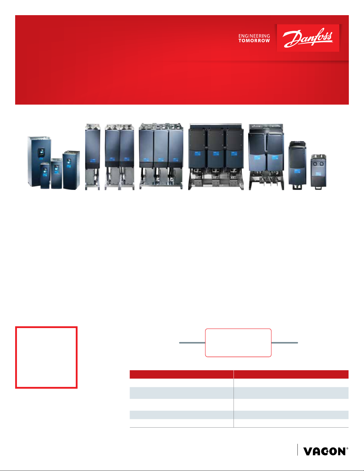
Ensure safe DC-grid selectivity with
VACON® NXP DCGuard™
VACON ® NXP DCGuard™* enables fast
disconnection and full selectivity between
DC grids.
Utilizing DC grids rather than AC grids
enables power distribution with lower
power losses. However, ensuring
selectivity and limited short circuit energy
requires more sophisticated protection
devices.
Current cut-off in
<5 µs
Danfoss Drives has therefore developed the
VACON ® NXP DCGuard™, a semiconductor
protection device that can detect and cut
off any faulty DC currents and isolate the
faulty part of the system in microseconds.
Current range:
n 465-800 VDC………3-4140 A
n 640-1100 VDC…..….4-3100 A
Easy dimensioning
Rated VACON® NXP DCGuard™ DC current =
Rated VACON® NXP Inverter AC current.
This means that your primary dimensioning
value is the required load through the
VACON® NXP DCGuard™, meaning energy
transfer from one side to another. It is as
easy as that.
Type approvals:
DNV-GL, ABS, Lloyd’s Register, CCS,
Bureau Veritas
Short Circuit
Protection
VACON® NXP DCGuard™
Feature Benefit
Short circuit protection Ensure correct system selectivity
Cuts off both + and - inside the same unit
Controlled voltage ramp up
Overload detection Protection of transmission cables
Standard NXP hardware Proven and well known products
No overvoltage spikes related to
current cut-off
Connect two different DC grids with
voltage differences up to full DC voltage
DC Grid 2DC Grid 1
*patent pending
www.danfossdrives.com
Page 2
Battery
Prospective fault
1200kWh
G1
2000kW
G2
2000kW
G3
2000kW
G4
2000kW
=
L L L
DC/DC
V
U
W
=
=
W
Filter Filter
Shore supply
2000kW
LCL LCL
U
~
Micro grid
U
V
~
V
W
=
AFE
=
W
V
Hotel load
200kW
AFE
V
U
W
~
=
DC Grid 1 DC Grid 2
Micro grid
U
~
Main propulsion
VACON® NXP DCGuard™
DCGuard1 DCGuard2
=
=
W
V
FWD
2000kW
DC+
DC-
INU
U
~
L
L
=
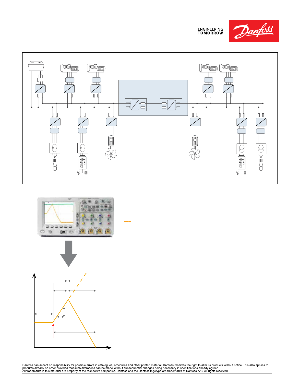
Example of hybrid system where VACON® NXP DCGuard™ ensures the required system selectivity
DC- link voltage on feeding side.
Negligible voltage dip on feeding side.
DC current in connection cables.
LCL
V
U
W
~
=
=
=
DC+
DC-
=
W
V
Main propulsion
AFT
2000kW
INU
U
~
L
L
AFE
LCL
AFE
V
U
W
~
=
Micro grid
=
W
U
V
~
Filter Filter
Hotel load
200kW
=
W
U
V
~
Shore supply
2500kW
Micro grid
DCGuard current
1
Fault
3
2
current
4
DCGuard
trip level
dI
dt
5
Legend
1. Normal situation(No fault)
Current is within DCGuard nominal
current capacity.
2. Fault current rise time.
Current dI/dt=V/L
V=Feeding DC voltage
L=Inductance in the circuit
Typical time:100-150µs*
3. Current cut off time.
DCGuard performs a current cut off
by forcing all IGBTs open when
4. Energy discharge time.
Current dI/dt=V/L
V=Feeding DC voltage
L=Inductance in the circuit
Typical time:100-150µs*
5. Total fault clearance time.
Typical time:200-300µs*
* System dependent
current reaches the tripping limit of
Time
DKDD.PFP.906.A4.22 © Copyright Danfoss Drives | 2019.11
the DCGuard. Time:<5µs
 Loading...