

Page 1

vacon nxp
®
ac drives
arfiff30
generator application
user manual
Page 2

Page 3

arfiff30 Generator VACON® • 3
Local contacts: http://drives.danfoss.com/danfoss-drives/local-contacts/
Classified as Business
VACON® GENERATOR APPLICATION MANUAL
INDEX
Document code: DPD01916B
Software code: ARFIFF30V122
Date: 2.6.2021
1. Generator Application ............................................................................................................................................ 7
2. Generator Versions compatibility issues ................................................................................................................ 8
3. Power Take Modes ................................................................................................................................................. 9
3.1 Power Take Out modes ................................................................................................................................... 9
3.1.1 Induction motor ......................................................................................................................................... 9
3.1.2 Permanent Magnet Synchronous Motor ..................................................................................................... 9
3.2 Synchronous machine ................................................................................................................................... 10
3.3 Power Take In modes ................................................................................................................................... 11
3.3.1 Induction Motor – Boosting ...................................................................................................................... 11
3.3.2 Induction Motor- Take Me Harbour. ......................................................................................................... 11
3.3.3 Permanent Magnet Synchronous Motor - Boosting ................................................................................... 11
3.3.4 Permanent Magnet Synchronous Motor – Take Me Harbour .................................................................... 12
3.3.5 Synchronous machine - Boosting .............................................................................................................. 12
3.3.6 Synchronous machine – Take Me Harbor .................................................................................................. 13
4. Main contactor control ........................................................................................................................................ 14
5. Control I/O ........................................................................................................................................................... 15
6. Monitoring signals................................................................................................................................................ 16
6.1 Monitoring ................................................................................................................................................... 16
6.1.1 Monitoring 1 Values ................................................................................................................................. 16
6.1.2 Monitoring 2 Values ................................................................................................................................. 17
6.1.3 Fieldbus Monitoring values ....................................................................................................................... 18
6.1.4 IO Monitoring values ................................................................................................................................ 18
6.1.5 Master Follower values ............................................................................................................................ 19
6.1.6 License code activation............................................................................................................................. 19
6.1.7 Line synch ................................................................................................................................................ 19
6.2 Monitoring Signal Descriptions ..................................................................................................................... 20
6.2.1 Monitoring 1 values.................................................................................................................................. 20
6.2.2 Monitoring 2 values.................................................................................................................................. 23
6.2.3 Fieldbus monitoring values ....................................................................................................................... 26
6.2.4 IO Monitoring values ................................................................................................................................ 31
6.2.5 Master Follower monitoring values .......................................................................................................... 33
7. ARFIFF30– Parameter list ..................................................................................................................................... 35
7.1 Basic Parameters (G2.1) ................................................................................................................................ 35
7.2 Reference Handling (G2.2) ............................................................................................................................ 36
7.2.1 PTM handling ........................................................................................................................................... 36
7.2.2 PTO handling ............................................................................................................................................ 36
7.2.3 PTI-Boost handling ................................................................................................................................... 37
7.2.4 PTI 0-Speed .............................................................................................................................................. 37
7.2.5 Regen Motor Mode .................................................................................................................................. 37
7.2.6 Commissioning ......................................................................................................................................... 38
Page 4

4 • VACON® arfiff30 Generator
Local contacts: http://drives.danfoss.com/danfoss-drives/local-contacts/
Classified as Business
7.2.7 DC Voltage Reference Handling ................................................................................................................ 38
7.2.8 Speed / Frequency Ref handling ............................................................................................................... 39
7.2.9 Torque Control ......................................................................................................................................... 39
7.2.10 Motor Potentiometer reference ........................................................................................................... 39
7.3 Ramp Control (G2.3) ..................................................................................................................................... 39
7.3.1 Ramp Control ........................................................................................................................................... 39
7.4 Input Signals (G2.4)....................................................................................................................................... 40
7.4.1 Basic settings............................................................................................................................................ 40
7.4.2 Digital Inputs ............................................................................................................................................ 41
7.4.3 Analogue Input 1 ...................................................................................................................................... 42
7.4.4 Analogue Input 2 ...................................................................................................................................... 42
7.4.5 Analogue Input 3 ...................................................................................................................................... 43
7.4.6 Analogue Input 4 ...................................................................................................................................... 43
7.5 Output Signals (G2.5) .................................................................................................................................... 44
7.5.1 Dig Out Signals ......................................................................................................................................... 44
7.5.2 Delayed DO 1 ........................................................................................................................................... 45
7.5.3 Delayed DO 2 ........................................................................................................................................... 45
7.5.4 Analog Output 1 ....................................................................................................................................... 47
7.5.5 Analog Output 2 ....................................................................................................................................... 47
7.5.6 Analog Output 3 ....................................................................................................................................... 48
7.5.7 Options .................................................................................................................................................... 48
7.5.8 Supervision limits ..................................................................................................................................... 48
7.6 Limit Settings (G2.6) ..................................................................................................................................... 49
7.6.1 Current Limit ............................................................................................................................................ 49
7.6.2 Power Limit .............................................................................................................................................. 49
7.6.3 Frequency Limit ........................................................................................................................................ 49
7.6.4 Voltage..................................................................................................................................................... 49
7.6.5 DC Voltage ............................................................................................................................................... 50
7.6.6 Torque ..................................................................................................................................................... 50
7.6.7 Active Current .......................................................................................................................................... 51
7.7 Flux and DC Current handling CL Settings (G2.7) ............................................................................................ 51
7.8 Motor Control (G2.8) .................................................................................................................................... 52
7.8.1 Motor Control Basic Settings .................................................................................................................... 52
7.8.2 U/f Settings .............................................................................................................................................. 52
7.8.3 PMSM Control settings ............................................................................................................................. 53
7.8.4 Stabilators ................................................................................................................................................ 54
7.8.5 Identification parameters ......................................................................................................................... 55
7.8.6 Tuning parameters ................................................................................................................................... 55
7.8.7 Flying Start Tuning parameters ................................................................................................................. 56
7.9 Speed Control (G2.9) .................................................................................................................................... 56
7.10 Drive Control (G2.10) .................................................................................................................................... 57
7.11 Master Follower (G2.11) ............................................................................................................................... 57
7.12 Protection (G 2.12) ....................................................................................................................................... 58
7.12.1 General ................................................................................................................................................ 58
7.12.2 Temperature Board parameters ........................................................................................................... 59
7.12.3 Earth fault ............................................................................................................................................ 59
7.12.4 External Fault ....................................................................................................................................... 59
7.12.5 Generator Voltage ................................................................................................................................ 60
7.12.6 Generator Frequency ........................................................................................................................... 60
7.12.7 Motor thermal protections ................................................................................................................... 60
7.12.8 Fieldbus protection .............................................................................................................................. 61
7.12.9 Cooling Monitoring .............................................................................................................................. 61
7.12.10 Options ................................................................................................................................................ 61
7.13 Fieldbus (G 2.13)........................................................................................................................................... 62
Page 5

arfiff30 Generator VACON® • 5
Local contacts: http://drives.danfoss.com/danfoss-drives/local-contacts/
Classified as Business
7.14 ID Control Functions (G2.14) ......................................................................................................................... 63
7.14.1 Value Control ....................................................................................................................................... 63
7.14.2 DIN ID Control 1 ................................................................................................................................... 63
7.14.3 DIN ID Control 2 ................................................................................................................................... 63
7.14.4 DIN ID Control 3 ................................................................................................................................... 64
7.15 Curve 1 definition (G2.15) ............................................................................................................................. 64
7.16 Curve 2 definition (G2.16) ............................................................................................................................. 65
7.17 Curve 3 definition (G2.17) ............................................................................................................................. 66
7.18 Line Synch (G2.18) ........................................................................................................................................ 67
7.19 Keypad control (Control keypad: Menu M3) .................................................................................................. 67
7.20 System menu (Control keypad: Menu M6) .................................................................................................... 67
7.21 Expander boards (Control keypad: Menu M7) ............................................................................................... 67
8. Parameter Descriptions ........................................................................................................................................ 68
8.1 Basic parameters .......................................................................................................................................... 68
8.2 Reference Handling ...................................................................................................................................... 74
8.2.1 PTM Handling ........................................................................................................................................... 74
8.2.2 PTO Handling ........................................................................................................................................... 74
8.2.3 PTI-Boost.................................................................................................................................................. 79
8.2.4 PTI 0-Speed .............................................................................................................................................. 81
8.2.5 Regen Motor ............................................................................................................................................ 82
8.2.6 Commissioning ......................................................................................................................................... 83
8.2.7 DC Voltage Reference ............................................................................................................................... 85
8.2.8 Speed and Frequency ............................................................................................................................... 86
8.2.9 Torque Control ......................................................................................................................................... 87
8.2.10 Ramp Control ....................................................................................................................................... 88
8.3 Input Signals ................................................................................................................................................. 89
8.3.1 Basic Settings ........................................................................................................................................... 89
8.3.2 Digital input signals .................................................................................................................................. 90
8.3.3 Analogue Inputs 1-4 ................................................................................................................................. 95
8.4 Output Signals .............................................................................................................................................. 98
8.4.1 Digital output signals ................................................................................................................................ 98
8.4.2 Delayed digital output 1 & 2 ................................................................................................................... 100
8.4.3 Analogue output 1 & 2 & 3 .................................................................................................................... 101
8.4.4 Options .................................................................................................................................................. 105
8.4.5 Supervision limits ................................................................................................................................... 107
8.5 Limit settings .............................................................................................................................................. 108
8.5.1 Current Limits......................................................................................................................................... 108
8.5.2 Power Limits .......................................................................................................................................... 108
8.5.3 Frequency limits ..................................................................................................................................... 110
8.5.4 Voltage................................................................................................................................................... 111
8.5.5 DC Voltage limit regulators ..................................................................................................................... 112
8.5.6 Torque ................................................................................................................................................... 114
8.5.7 Active Current ........................................................................................................................................ 114
8.6 Flux Control ................................................................................................................................................ 115
8.7 Motor Control ............................................................................................................................................ 116
8.7.1 U/f Settings ............................................................................................................................................ 117
8.7.2 Close Loop Settings ................................................................................................................................ 124
8.7.3 Permanent magnet synchronous motor settings ..................................................................................... 126
8.7.4 Stabilization settings............................................................................................................................... 132
8.7.5 Identification settings ............................................................................................................................ 136
8.7.6 Flying Start ............................................................................................................................................. 138
8.8 Speed Control settings ................................................................................................................................ 139
8.9 Drive Control .............................................................................................................................................. 141
Page 6

6 • VACON® arfiff30 Generator
Local contacts: http://drives.danfoss.com/danfoss-drives/local-contacts/
Classified as Business
8.10 Master Follower ......................................................................................................................................... 148
8.10.1 Master Follower: DriveSynch system .................................................................................................. 148
8.10.2 Master follower configuration ............................................................................................................ 151
8.11 Protections ................................................................................................................................................. 153
8.11.1 General settings ................................................................................................................................. 153
8.11.2 Temperature Board ............................................................................................................................ 156
8.11.3 Earth Fault ......................................................................................................................................... 158
8.11.4 External Fault ..................................................................................................................................... 158
8.11.5 Generator Voltage OPT-D7 ................................................................................................................. 159
8.11.6 Generator Frequency OPT- D7 ............................................................................................................ 160
8.11.7 Motor Protection ............................................................................................................................... 161
8.11.8 Over Load Protection ......................................................................................................................... 163
8.11.9 Fieldbus communication .................................................................................................................... 165
8.11.10 Cooling protection.............................................................................................................................. 165
8.11.11 Protection Options ............................................................................................................................. 166
8.12 Fieldbus ...................................................................................................................................................... 167
8.12.1 Signals from drive to Fieldbus ............................................................................................................. 167
8.12.2 Signals from fieldbus to drive ............................................................................................................. 167
8.13 ID Functions ............................................................................................................................................... 169
8.13.1 Value Control ..................................................................................................................................... 169
8.13.2 DIN ID Control .................................................................................................................................... 172
8.14 Curve 1 Definition ....................................................................................................................................... 173
8.15 Curve 2 Definition ....................................................................................................................................... 173
8.16 Curve 3 Definition ....................................................................................................................................... 173
8.17 Line synch .................................................................................................................................................. 174
9. Keypad control parameters ................................................................................................................................ 175
10. Status and control words in detail.................................................................................................................. 176
10.1 Basic In ByPass (0) ...................................................................................................................................... 176
10.2 FB Control Word ......................................................................................................................................... 177
10.2.1 Standard (1) ....................................................................................................................................... 177
10.2.2 Vacon Generator 1 profile (2) ............................................................................................................. 178
10.2.3 Vacon AFE 2 Profile (Not Implemented as of 1.7.2014) ....................................................................... 180
10.3 FB Status Word ........................................................................................................................................... 182
10.4 Status Word (Application) ID 43 .................................................................................................................. 184
11. Problem solving ............................................................................................................................................. 186
12. FAULT CODES ................................................................................................................................................. 187
Page 7

arfiff30 Generator VACON® • 7
Local contacts: http://drives.danfoss.com/danfoss-drives/local-contacts/
Classified as Business
1. Generator Application
Software ARFIFF30, Generator application
The VACON® Generator application is an application that can be used to keep constant DC Voltage
regardless of input power source. The application supports Synchronous Generator (LCL Needed),
Permanent Magnet Synchronous Motor (Absolute Encoder needed) and asynchronous motor
(Incremental Encoder needed).
VACON® Generator application also support PTI operations. However, this manual does include
details on related hardware selections. We recommend you read the Grid Converter technical
documentation and contact VACON® technical support for more details.
The basic I/O-configuration of the AC drive consists of OPT-A1, OPT-A2 and if needed OPT-D7 or
OPT-A5 option cards depending of what type of generator is used. Also, for commissioning purposes
it is recommended to use OPT-D2 board. The basic I/O configuration has been described in table 2-1.
As a default the control place (P3.1) of the Generator drive is Keypad.
This application requires NXP3 control board 761 or newer.
Page 8

8 • VACON® arfiff30 Generator
Local contacts: http://drives.danfoss.com/danfoss-drives/local-contacts/
Classified as Business
2. Generator Versions compatibility issues
V095
• Frequency Reference monitoring signal ID number changed from ID1752 to ID25
o 1752 is reserved for P 2.8.7.4 DeadTieContCurL
V101
• P2.2.4.5 TorqueRefRampTime is removed and internally forced to zero.
• New parameter for new ramp handling
o P2.2.4.5 TRefRampUpRate ID1934
o P2.2.4.6 TRefRampDownRate ID1935
• P2.2.4.5 TorqueRefRampTime was ramping regardless of Run state. With long
ramp time torque reference did not ramp to new reference fast enough e.g. when
changing between PTO and PTI-Boost modes.
• TRefRampUpRate is ramp rate when absolute value is increasing.
• TRefRampDownRate is ramp rate when negative or positive value is going toward
zero.
Note 1: When updating application, it is not recommended to use VACON® NCDrive parameter
download function. Instead, upload the parameters from the unit and make comparison to the old
parameter file. Application is constantly developed; this includes changing parameter default values.
If parameters are directly downloaded to drive, the improved default values will be lost.
Page 9
arfiff30 Generator VACON® • 9
Local contacts: http://drives.danfoss.com/danfoss-drives/local-contacts/
Classified as Business
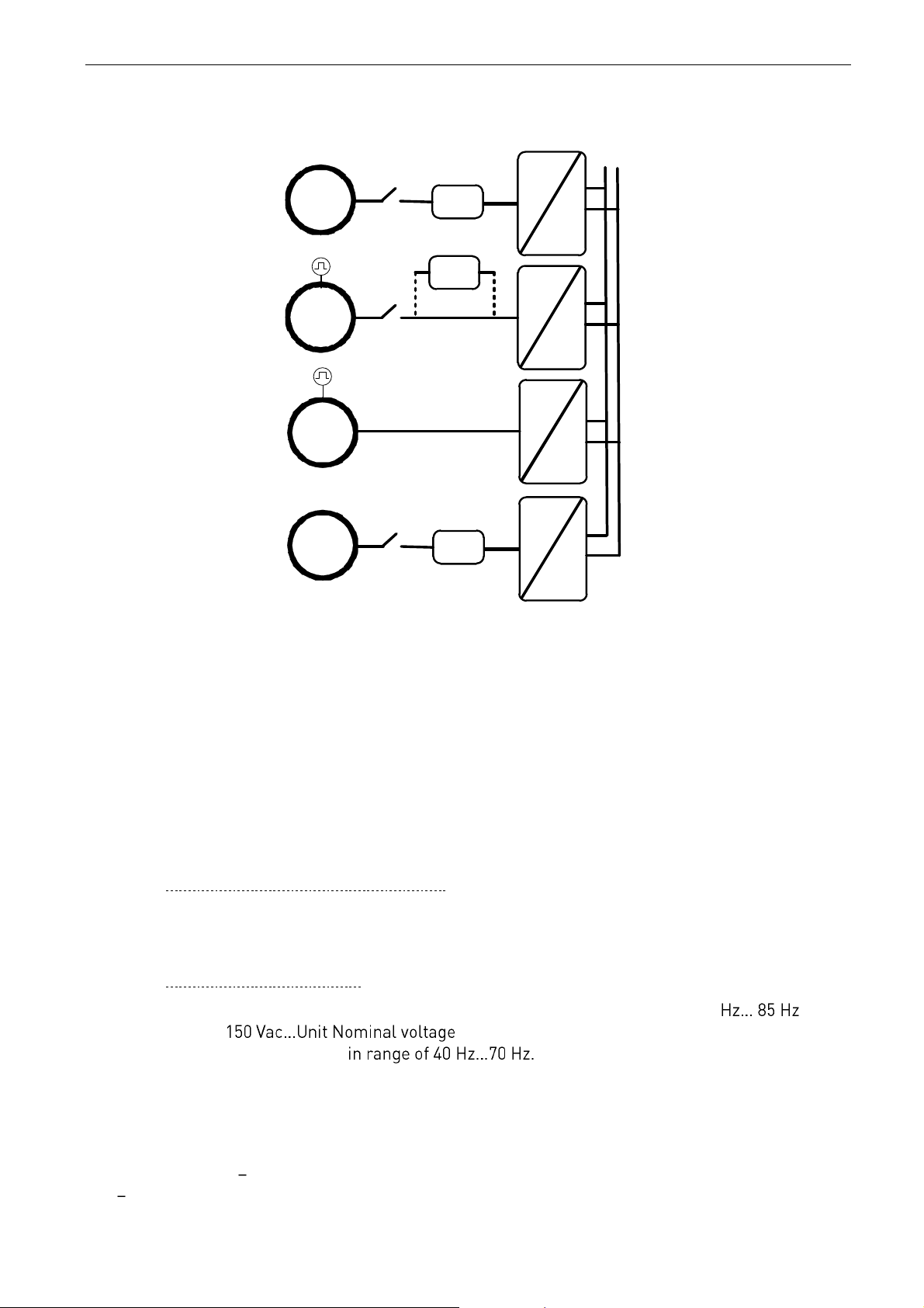
3. Power Take Modes
U2
=
~
Filter
SG
U1
Q2
=
~
Filter
PMG
U1
Q2
U2
=
~
IMG
U2
=
~
Filter
SM
U1
Q2
UDC
U2
Figure 3-1.
3.1 Power Take Out modes
3.1.1 Induction motor
AC drive is operated in closed loop control. Closed Loop is needed to have good response to power
demand changes. AC drive will be set to operate in DC Reference mode with negative torque
reference, which can be handled in G2.2.1.6 PTO group, when Power Take mode is PTO. Torque
reference can be handled by using curve reference mode or with direct control from upper system.
3.1.1.1
Induction motor in open loop control.
Pure open loop control can be used on cases were generator drive is not required to keep the DC
stable, e.g. when grid side drive can be kept in AFE mode.
3.1.1.2
Regenerative Motor Mode
This mode can be used in open loop mode but involve limits for frequency range: 30 and
for voltage range: . When starting this operation mode, the
recommended generator speed is This mode requires licence code. To
get the licence, provide the technical details beforehand to VACON® Finland for approval.
3.1.2 Permanent Magnet Synchronous Motor
Depending on the system requirements, the PMSM can be controlled in normal motor control modes
or AFE mode. If PTI TMH is also needed, we recommend the normal motor control mode. If only
PTI Boosting is needed, the system may be possible to operate in AFE mode.
Page 10

10 • VACON® arfiff30 Generator
Local contacts: http://drives.danfoss.com/danfoss-drives/local-contacts/
Classified as Business
PMSM in normal motor control modes needs to be operated in closed loop control to have a good
response time to the changes in power demand.
AFE mode can be used without filter if motor can be run with unity power factor. AFE can
compensate if inductor size is programmed according to stray inductance of PM motor and stray
inductance voltage is over half of BEM voltage, if not, LC filter is enough. When paralleling, LCL is
needed
3.2 Synchronous machine
This is normal AFE operation.
Page 11

arfiff30 Generator VACON® • 11
Local contacts: http://drives.danfoss.com/danfoss-drives/local-contacts/
Classified as Business
3.3 Power Take In modes
PTI needs to be separated to two different modes. In all modes the DC Voltage needs to be kept
constant with the Grid side drive (or otherwise have suitable DC Voltage available). When using the
Grid Converter application on grid side, change the operation mode to AFE operation mode. Constant
DC Voltage can be also kept with the uGrid operation mode when special care of references and limit
values in PMS has been take care of.
PTI - Boosting.
In this mode the generator (motor) is already rotating when more power is started to be fed to the
generator (motor). When the PTI is started, we recommend a minimum frequency limit of ~20 Hz for
the drive is. Above this limit, the operation is considered to be boosting.
PTI TMH (Take Me Harbour)
In this mode, the generator (motor) needs to be started from zero speed. You can do this for
example so that the main engine is not running and the propeller power is taken from the diesel
generator using existing shaft generator system.
3.3.1 Induction Motor – Boosting
3.3.1.1
In DC Voltage Reference mode
While in PTO mode, the AC drive is operated in the torque reference mode. When you change the
operation mode to boosting, you can simply put the AC drive torque reference to positive direction.
3.3.1.2
In Speed Reference Mode
In this mode, the AC drive will follow the speed reference of the PMS. Usually the power capacity of
the Shaft Generator system is only a fraction of the main engine power capacity. Therefore, you need
to check the power, torque and current limitations.
3.3.2 Induction Motor- Take Me Harbour.
In this mode, the AC drive will follow the speed reference of the PMS Usually the power capacity of
the Shaft Generator system is only a fraction of the main engine power capacity. Therefore, you need
to check the power, torque and current limitations.
3.3.3 Permanent Magnet Synchronous Motor - Boosting
Depending on the system requirements, the PMSM can be controlled in normal motor control modes
or AFE mode. If PTI TMH is also needed, we recommend the normal motor control mode. If only
PTI Boosting is needed and there is space for sine filter, the system can be operated in AFE mode.
3.3.3.1
Operating in AFE Mode, DC Voltage Reference Mode
Change is made only between PTO and PTI Boosting mode.
When the AC drive is operating in PTO mode, the constant DC Voltage in maintained. When you
change to the Boosting mode, the constant DC Voltage needs to be kept with grid side drive. When
the grid side drive keeps the constant DC Voltage, the DC Voltage Reference can be set lower on the
generator side drive thus changing the power flow direction. To be able to control the power flow,
the PMS needs to control the Output Power.
Page 12

12 • VACON® arfiff30 Generator
Local contacts: http://drives.danfoss.com/danfoss-drives/local-contacts/
Classified as Business
3.3.3.2
Operating in AFE Mode, Speed Reference Mode
This operation mode is not possible.
3.3.3.3
Operating in normal motor control mode, DC Voltage Reference Mode
While in PTO mode, the AC drive is operated in the torque reference mode. When you change the
operation mode to boosting, you can simply put the AC drive torque reference to positive direction.
With this selection, the PMS will control the positive torque reference thus defining boosting torque.
3.3.3.4
Operating in normal motor control mode. Speed Reference Mode
In this mode, the AC drive will follow the speed reference of the PMS. Usually the power capacity of
the Shaft Generator system is only a fraction of the main engine power capacity. Therefore, you need
to check the power, torque and current limitations.
3.3.4 Permanent Magnet Synchronous Motor – Take Me Harbour
This control can be made only by using the normal motor control modes. AFE mode cannot start
from below 25 Hz.
3.3.4.1
Operating in normal motor control mode, DC Voltage Reference Mode
While in PTO mode, the AC drive is operated in the torque reference mode by using selection 1 /
Curve in P2.2.9.1 Torque Ref Select. When you change the operation mode to boosting, you need to
set the reference to positive direction. With this selection, the PMS will control the positive torque
reference thus defining torque to be used for propulsion.
3.3.4.2
Operating in normal motor control mode. Speed Reference Mode
In this mode, the AC drive will follow the speed reference of the PMS. Usually the power capacity of
the Shaft Generator system is only a fraction of the main engine power capacity. Therefore, you need
to check the power, torque and current limitations.
3.3.5 Synchronous machine - Boosting
3.3.5.1
Operating in AFE Mode, DC Voltage Reference Mode
Change is made only between PTO and PTI Boosting mode.
While the AC drive is operating in the PTO mode, the constant DC Voltage is maintained. When you
change to the Boosting mode, the constant DC Voltage needs to be kept with grid side drive. When
the grid side drive keeps the constant DC Voltage, the DC Voltage Reference can be set lower in the
generator side thus changing power flow direction. To be able to control power flow, the PMS needs
to control the Output Power limit P2.6.2.1 OutputPowerLim.
3.3.5.2
Operating in AFE Mode, Speed Reference Mode
This operation mode is not possible.
3.3.5.3
Operating in normal motor control mode, DC Voltage Reference Mode
Not supported nor recommended.
3.3.5.4
Operating in normal motor control mode. Speed Reference Mode
Not supported nor recommended.
Page 13

arfiff30 Generator VACON® • 13
Local contacts: http://drives.danfoss.com/danfoss-drives/local-contacts/
Classified as Business
3.3.6 Synchronous machine – Take Me Harbor
This operation mode is only possible in the normal motor control modes.
3.3.6.1
Operating in normal motor control mode, DC Voltage Reference Mode
Not supported nor recommended
3.3.6.2
Operating in normal motor control mode. Speed Reference Mode
Change is made only between PTO and PTI TMH.
While the AC drive is operating in PTO mode, the constant DC Voltage is maintained. When you
change to PTI - TMH mode, the constant DC Voltage needs to be kept with grid side drive.
In this mode the AC drive will follow the speed reference of the PMS Usually the power capacity of
the Shaft Generator system is only a fraction of the main engine power capacity. Therefore, you need
to check the power, torque and current limitations.
Page 14

14 • VACON® arfiff30 Generator
Local contacts: http://drives.danfoss.com/danfoss-drives/local-contacts/
Classified as Business
4. Main contactor control
The Generator application controls the MCB (Main Circuit Breaker) of the system with selectable
Relay Output. When charging of the DC bus is ready, the MCB will be closed. The status of the MCB
is monitored via digital input. Digital input used for monitoring is chosen with parameter P2.4.2.4.
When a fault occurs, the MCB will be opened after one second so the drive will go to stop state
first. In case of F1 Over Current, F2 Over Voltage or F31 and F41 IGBT faults, the breaker is opened
immediately. If the charging is on when the fault is acknowledged the MCB will be closed.
An external charging circuit is needed to charge the DC bus.
Page 15
arfiff30 Generator VACON® • 15
Local contacts: http://drives.danfoss.com/danfoss-drives/local-contacts/
Classified as Business
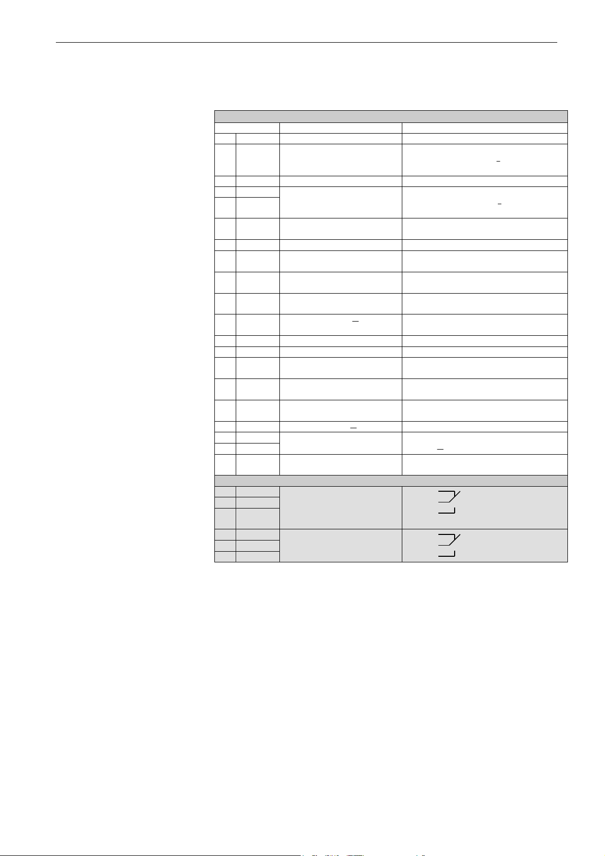
5. Control I/O
OPT-A1
Terminal
Signal
Description
1
+10Vref
Reference voltage output
Voltage for potentiometer, etc.
2
AI1+
Analogue input 1.
Range 0-10V, Ri = 200
Range 0-20 mA Ri = 250
Input range selected by jumpers.
Default range: Voltage 0 10 V
3
AI1-
I/O Ground
Ground for reference and controls
4
AI2+
Analogue input 2.
Range 0-10V, Ri = 200
Range 0-20 mA Ri = 250
Input range selected by jumpers.
Default range: Current 0 20 mA
5
AI2-
6
+24V
Control voltage output
Voltage for switches, etc. max 0.1 A
7
GND
I/O ground
Ground for reference and controls
8
DIN1
Start
Programmable G2.2.1
0=Stop,
1=Run
9
DIN2
Programmable G2.2.1
No function defined at default
10
DIN3
Programmable G2.2.1
No function defined at default
11
CMA
Common for DIN 1 DIN 3
Connect to GND or +24V
12
+24V
Control voltage output
Voltage for switches (see #6)
13
GND
I/O ground
Ground for reference and controls
14
DIN4
Main contactor supervision
Programmable G2.2.1
0 = contactor open
1 = contactor closed
15
DIN5
Programmable G2.2.1
No function defined at default
16
DIN6
Fault reset
Programmable G2.2.1
Rising edge will reset active faults
17
CMB
Common for DIN4 DIN6
Connect to GND or +24V
18
AO1+
Analogue output 1
Programmable
Range 0 20 mA/RL, max. 500
19
AO1-
20
DO1
Digital output
READY
Programmable P2.3.1.1
Open collector, I50mA, U48 VDC
OPT-A2
21
RO1
Relay output 1
Programmable P2.3.1.2
Switching capacity
24 VDC / 8 A
22
RO1
23
RO1
250 VAC / 8A
125 VDC / 0.4 A
24
RO2
Relay output 2
Main contactor control
This RO is not programmable.
Fixed for Main Contactor Control
25
RO2
26
RO2
Table 5-1 Default I/O configuration.
Reference
Page 16
16 • VACON® arfiff30 Generator
Local contacts: http://drives.danfoss.com/danfoss-drives/local-contacts/
Classified as Business
6. Monitoring signals
Menu M1 (Monitoring) holds all the monitoring values. Values are only for monitoring, and cannot be
altered by the panel.
6.1 Monitoring
6.1.1 Monitoring 1 Values
Code
Parameter
Unit
Form.
ID
Description
V1.1.1
DC-Link Voltage
V # 1108
DC Voltage filtered
V1.1.2
DC Voltage Ref.
%
#,##
1200
Used DC voltage reference by the
regenerative unit in % of Nominal DC
Voltage.
Nominal DC voltage = 1.35 * Supply
voltage
V1.1.3
DC Voltage Actual
%
#,##
7
Same scaling as DC Voltage Ref.
V1.1.4
Total Current
A
Varies
1104
Filtered current
V1.1.5
Active Current
%
#,#
1125 V1.1.6
Reactive Current
%
#,#
1157 V1.1.7
Power kW
kW
Varies
1508 V1.1.8
Power %
%
#,#
5 V1.1.9
Status Word
# 43 V1.1.10
Supply Frequency
Hz
#,##
1
Drive output frequency
V1.1.11
Supply Voltage
V
#,#
1107
Drive output voltage
V1.1.12
LineFrequency D7
Hz
#,##
1654
Measured line frequency
V1.1.13
Line Voltage D7
V # 1650
Measured line voltage
V1.1.14
AC Voltage Reference
V # 1556 V1.1.15
DC Ref Max Lim
%
#,##
1606 V1.1.16
Encoder 1 Freq.
Hz
#,##
1164 V1.1.17
Torque Reference
%
#,#
18 V1.1.18
Final Torque Reference
%
#,#
1145 V1.1.19
Actual Torque Reference
%
#,#
1180 V1.1.20
Motor Torque
%
#,#
4
Filtered
V1.1.21
Motor Speed
rpm # 2
Table 6-1, Monitoring 1
Page 17
arfiff30 Generator VACON® • 17
Local contacts: http://drives.danfoss.com/danfoss-drives/local-contacts/
Classified as Business
6.1.2 Monitoring 2 Values
Code
Parameter
Unit
Form.
ID
Description
V1.2.1
DC Voltage
V # 44
Measured DC Link voltage in
Volts, unfiltered.
V1.2.2
Cos Phii Actual
#,###
1706 V1.2.3
Unit Temperature
°C # 1109 V1.2.4
Freq Reference
Hz
#,##
25
Used line frequency reference
V1.2.5
Current
A
Varies
1113
Unfiltered current
V1.2.6
Operation Hours
h
#,#
1856
V1.2.7
Reactive Current
Reference
%
#,#
1389
V1.2.8
Power Take Mode
# 1925 V1.2.9
Torque
%
#,#
1134
Unfiltered
V1.2.10
Limit & Regulators
# 77 V1.2.11
Shaft Frequency
Hz
#,##
1124 V1.2.12
U Phase Current
A
Varies
39 V1.2.13
V Phase Current
A
Varies
40 V1.2.14
W Phase Current
A
Varies
41
V1.2.15
Fault Word 10
1202
V1.2.16
Warning Word 10
1269
Table 6-2, Monitoring 2
Page 18
18 • VACON® arfiff30 Generator
Local contacts: http://drives.danfoss.com/danfoss-drives/local-contacts/
Classified as Business
6.1.3 Fieldbus Monitoring values
Code
Parameter
Unit
Form.
ID
Description
V1.3.1
FB Control Word
# 1160
Control word from fieldbus
V1.3.2
FB Status Word
# 68
Status word to fieldbus
V1.3.3
FB Actual Value
# 865 V1.3.4
FB Speed Ref
# 875 V1.3.5
FB Torque Ref
#,#
1140 V1.3.6
Generator CW
# 1700 V1.3.7
Generator SW
# 1701 V1.3.8
Fault Word 1
# 1172 V1.3.9
Fault Word 2
# 1173 V1.3.10
Warning Word 1
# 1174 V1.3.11
Last Active Warning
# 74 V1.3.12
Last Active Fault
# 37 V1.3.13
Speed FB Scaled
#,##
1907 V1.3.14
FB Analog Out
%
#,##
48
Table 6-3, Fieldbus
6.1.4 IO Monitoring values
Code
Parameter
Unit
Form.
ID
Description
V1.4.1
DIN1, DIN2, DIN3
# 15 V1.4.2
DIN4, DIN5, DIN6
# 16
V1.4.3
DIN Status 1
# 56
V1.4.4
DIN Status 2
# 57
V1.4.5
Analogue Input 1
%
#,##
13
V1.4.6
Analogue Input 2
%
#,##
14
V1.4.7
Analogue input 3
%
#,##
27
AI3, unfiltered.
V1.4.8
Analogue input 4
%
#,##
28
AI4, unfiltered.
V1.4.9
Analogue Out 1
%
#,##
26
V1.4.10
Analogue Out 2
%
#,##
50
AO2
V1.4.11
Analogue Out 3
%
#,##
51
AO3
V1.4.12
PT100 Temp. 1
°C
#,#
50 V1.4.13
PT100 Temp. 2
°C
#,#
51 V1.4.14
PT100 Temp. 3
°C
#,#
52 V1.4.15
PT100 Temp. 4
°C
#,#
69 V1.4.16
PT100 Temp. 5
°C
#,#
70
V1.4.17
PT100 Temp. 6
°C
#,#
71
V1.4.18
PT100 Max Temperature
°C
#,#
42
Table 6-4, IO monitoring
Page 19
arfiff30 Generator VACON® • 19
Local contacts: http://drives.danfoss.com/danfoss-drives/local-contacts/
Classified as Business
6.1.5 Master Follower values
Code
Parameter
Unit
Form.
ID
Description
V1.5.1
SB System Status
# 1800 V1.5.2
System Current
A
Varies
80 V1.5.3.1
Current D1
Varies
1820 V1.5.3.2
Current D2
Varies
1821 V1.5.3.3
Current D3
Varies
1822 V1.5.3.4
Current D1
Varies
1823 V1.5.4.1
Status Word D1
# 1828 V1.5.4.2
Status Word D2
# 1829 V1.5.4.3
Status Word D3
# 1830 V1.5.4.4
Status Word D4
# 1831
Table 6-5, Master follower
6.1.6 License code activation
Code
Parameter
Unit
Form.
ID
Description
V1.6.1
License Status
# 1996
V1.6.2
Serial Number Key
# 1997
Give this number to VACON®
technical support in case of
License Key problems.
Table 6-6, Activation
6.1.7 Line synch
Code
Parameter
Unit
Form.
ID
Description
V1.7.1
Line Synch Error
#,#
1659
Table 6-7, Line synch
Page 20

20 • VACON® arfiff30 Generator
Local contacts: http://drives.danfoss.com/danfoss-drives/local-contacts/
Classified as Business
6.2 Monitoring Signal Descriptions
6.2.1 Monitoring 1 values
V1.1.1 DC Voltage V ID1108
Measured DC voltage, filtered.
V1.1.2 DC Voltage Ref. % ID1200
DC voltage reference. Compared to given supply voltage.
1.35 * Supply Voltage * DC Voltage Ref = DC Voltage
V1.1.3 DC Voltage Actual % ID7
DC voltage actual in same scale as V1.1.2 DC Voltage Reference.
V1.1.4 Total Current A ID 1113
Filtered current of the drive.
V1.1.5 Active Current % ID 1125
Active current in % of System Rated Current.
Active Current > 0: Current flow from Drive DC-Link to AC-Side.
Active Current < 0: Current flow from AC-Side to Drive DC-Link.
V1.1.6 Reactive Current % ID 1157
Reactive current of the regenerative drive in % of System Rated Current.
V1.1.7 Power kW [kW] ID 1508
Drive output power in kW.
AFE control modes:
Power kW > 0: Current flow from AC-Side to Drive DC-Link.
Power kW < 0: Current flow from Drive DC-Link to AC-Side.
Motor control modes:
Power kW > 0: Current flow from Drive DC-Link to AC-Side.
Power kW < 0: Current flow from AC-Side to Drive DC-Link.
V1.1.8 Power % % ID 5
Drive output power in %.
Negative value means that current is flowing to AC side from DC side.
Page 21
arfiff30 Generator VACON® • 21
Local contacts: http://drives.danfoss.com/danfoss-drives/local-contacts/
Classified as Business
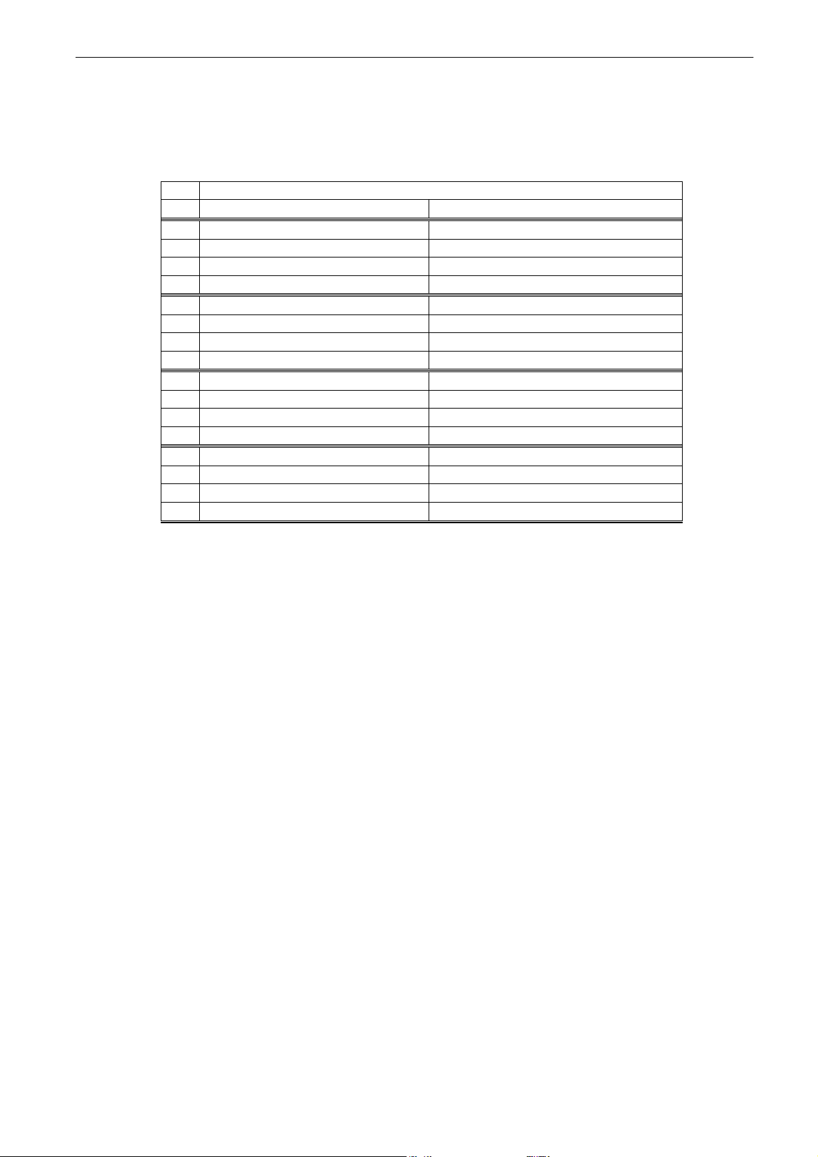
V1.1.9 Status Word (Application) ID 43
Application Status Word combines different drive statuses to one data word.
Application Status Word ID43
FALSE
TRUE
b0
No Charge Command
Charge Command Active
b1
Not in Ready state
Ready
b2
Not Running
Running
b3
No Fault
Fault
b4
No Start Request
Start Request Active
b5
Quick stop active
Quick stop not active
b6
Run Disabled
Run Enable
b7
No Warning
Warning
b8 Charging Switch closed (internal)
b9 Main Contactor Control (DO Final)
b10 Main Contactor Feedback
b11
b12
No Run Request
Run Request
b13 PTO
b14 PTI
b15 Regen
Table 6-8, Application status word
V1.1.10 Supply Frequency Hz ID 1
Drive output frequency. Updated in stop state when Regen Options B9 is activated.
V1.1.11 Supply Voltage V ID 1107
Drive output voltage.
V1.1.12 Line Frequency D7 Hz ID 1654
Measured Line Voltage Frequency when using OPT-D7 option board in slot C.
V1.1.13 Line Voltage D7 [V] ID 1650
Measured line voltage rms value when using OPT-D7 option board in slot C.
V1.1.14 AC Voltage Reference [V] ID1556
AC side voltage reference.
V1.1.15 DC Voltage max limit ID1606
Drive will limit DC Reference to inside drive specification but allows higher reference if
lover supply voltage. This shows the final limit of DC reference.
Page 22

22 • VACON® arfiff30 Generator
Local contacts: http://drives.danfoss.com/danfoss-drives/local-contacts/
Classified as Business
V1.1.16 Encoder 1 Frequency Hz ID 1164
Encoder frequency directly from encoder
V1.1.17 Torque reference % ID 18
Torque reference value before load share.
V1.1.18 Final Torque Ref % ID1145
Final torque reference in torque reference chain, before acceleration compensation
and speed controller output.
V1.1.19 Actual Torque Reference % ID1180
Final torque reference from speed control and torque control. Also includes torque step
and acceleration compensation factors.
V1.1.20 Motor torque % ID 4
In % of Motor nominal torque
Open loop
1 s linear filtering
Closed Loop
32 ms filtering
V1.1.21 Motor Speed rpm # ID2
Estimated motor speed.
Page 23

arfiff30 Generator VACON® • 23
Local contacts: http://drives.danfoss.com/danfoss-drives/local-contacts/
Classified as Business
6.2.2 Monitoring 2 values
V1.2.1 DC Voltage V ID44
The measured DC voltage, unfiltered.
V1.2.2 CosPhiActual ID 1706
The calculated Cos Phi.
V1.2.3 Unit Temperature °C ID 1109
The heatsink temperature of the drive.
V1.2.4 Freq Reference Hz ID25
Used frequency reference. In AFE mode frequency reference is determined internally
when synchronization is made.
V1.2.5 Current A ID 1113
Unfiltered current of the drive.
V1.2.6 Operation Hours h ID1856
This shows operation hours of the drive. P2.7.19 is used to enter old value if software is
updated.
V1.2.7 Reactive Current Reference % ID1389
Final reactive current reference.
V1.2.8 Power Take Mode Used ID1925
0 = Commissioning.
1 = Power Take Out.
2 = Power Take In, Boost.
3 Power Take In, From Zero Speed.
V1.2.9 Torque % ID 1125
Unfiltered motor torque, recommended signal for NCDrive monitoring.
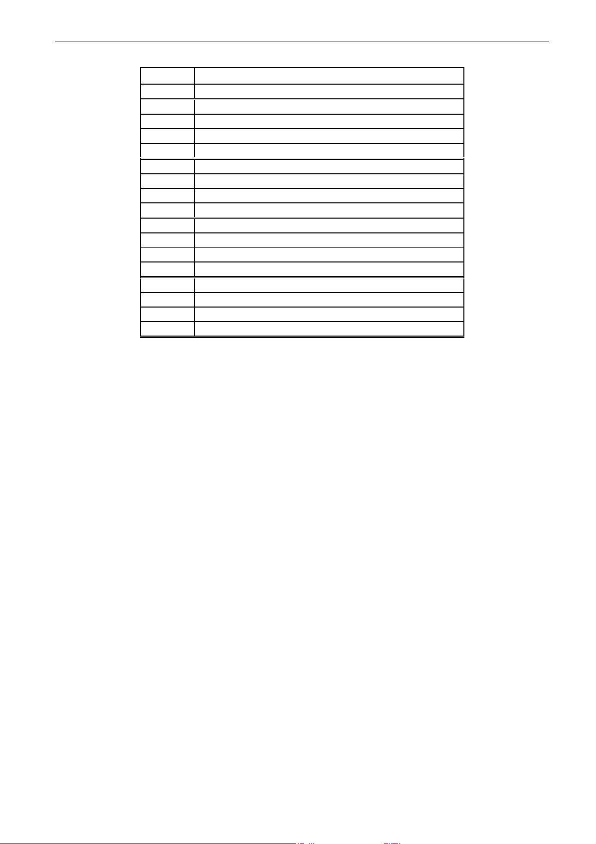
V1.2.10 Limits and Regulators ID77
Page 24
24 • VACON® arfiff30 Generator
Local contacts: http://drives.danfoss.com/danfoss-drives/local-contacts/
Classified as Business
Limit & Regulators ID77
Bit
B0
Motoring Current Limit
B1
Generator Current Limit
B2
Motoring Torque Limit
B3
Generator Torque Limit
B4
Over Voltage Requlator
B5
Under Voltage Regulator
B6
Positive Speed Controller Limit
B7
Negative Speed Controller Limit
B8
Positive Iq Limit
B9
Negative Iq Limit
B10
Motoring Power Limit Active
B11
Generator Power Limit Active
B12
B13
B14
B15
Table 6-10, Limits and regulators
V1.2.11 Shaft Frequency ID1124
Shaft Frequency used by motor control
V1.2.12 U Phase Current A ID39
V1.2.13 V Phase Current A ID40
V1.2.14 W Phase Current A ID41
Phase current in rpm, 1 second linear filtering.
Page 25
arfiff30 Generator VACON® • 25
Local contacts: http://drives.danfoss.com/danfoss-drives/local-contacts/
Classified as Business
V1.2.15 Fault Word 10 ID1202
Fault Word 10
Bit
Fault(s)
B0
B1
B2
F82 Overload Fault
B3
B4
F56 & F65 PT100 Temperature
B5
B6
B7
B8 B9 B10 B11 B12
B13
B14 B15
V1.2.15 Warning Word 10 ID1269
Warning Word 10
Bit
Fault(s)
B0 B1
W3 Earth Fault
B2
W82 Overload fault
B3
B4
W56 & W65 PT100 Temperature
B5 B6 B7
B8
B9 B10 B11 B12 B13 B14
B15
Page 26
26 • VACON® arfiff30 Generator
Local contacts: http://drives.danfoss.com/danfoss-drives/local-contacts/
Classified as Business
6.2.3 Fieldbus monitoring values
V1.3.1 FB Control Word ID 1160
Control word from fieldbus. The table below shows the bypass operation for such fieldbus boards
that natively support the bypass operation or can be parameterized to bypass mode.
FB Control Word ID1160
Signal
Comment
B00
DC Charge
0= Open MCB.
1= Close DC charge contactor, CB closed automatically.
B01
B02
B03
Run
0= AFE is stopped
1= AFE is started
B04
B05
B06
B07
Reset
0>1 Reset fault.
B08
B09
B10
Fieldbus Control
0= No control from fieldbus
1=Control from fieldbus
B11
Watchdog
communication between fieldbus master and the drive.
B12
FB DIN2
Can be used to control RO or directly parameter by ID number.
G2.4.1
B13
FB DIN3
Can be used to control RO or directly parameter by ID number.
G2.4.1
B14
FB DIN4
Can be used to control RO or directly parameter by ID number.
G2.4.1
B15
Reserved for future use.
Table 6-10, Fieldbus control word
Page 27
arfiff30 Generator VACON® • 27
Local contacts: http://drives.danfoss.com/danfoss-drives/local-contacts/
Classified as Business
V1.3.2 FB Status Word ID 68
Status word to fieldbus. The table below shows the bypass operation for such fieldbus boards that
natively support the bypass operation or can be parameterized to bypass mode.
Signal
Comment
b0
Ready On
0=Drive not ready to switch on
1=Drive ready to start charging
b1
Ready Run
0=Drive not ready to run
1=Drive ready and MCB is ON
b2
Running
0=Drive not running
1=Drive in Run state (Modulating)
b3
Fault
0=No active fault
1=Fault is active
b4
Run Enable Status
0= Run Disabled. Drive in stop state
1= Run Enabled. Drive can be started.
b5
Quick Stop Active
0=Quick Stop Active
1=Quick Stop not Active
b6
CB Control OK
0= Status opposite of control
1= Status and control OK
b7
Warning
0= No active warnings
1= Warning active
b8
At Reference
0= DC Voltage Ref and Act DC Voltage are not
same.
b9
Fieldbus Control Active
0=Fieldbus control not active
1=Fieldbus control active
b10
Above Limit
0= DC Voltage is below P2.5.5.2 level
1=The DC Voltage is above the P2.5.5.2 level
b11
Reserved for future use.
b12
Reserved for future use.
b13
Reserved for future use.
b14
DC Charge DO Control
0= DC not charged
1= DC Charging Active
b15
Watchdog
Same as received on bit 11 of the main control
word.
Table 6-11, Fieldbus status word
V1.3.3 FB Actual Value ID865
Use Process data ID to drive this value.
V1.3.4 FB Speed Reference ID875
Use Process data ID to drive this value.
V1.3.5 FB Torque Reference ID1140
Use Process data ID to drive this value.
Page 28
28 • VACON® arfiff30 Generator
Local contacts: http://drives.danfoss.com/danfoss-drives/local-contacts/
Classified as Business
V1.3.6 Generator Control Word ID1700
FALSE
TRUE
b0
b1
b2
b3
b4
b5
b6
b7
b8
b9
b10
b11
b12
b13
b14
b15
Table 6-12, Generator control word
V1.3.7 Generator Status Word ID1701
FALSE
TRUE
b0 Generation Operation Selected
b1 DC Control Active
b2
b3
b4
b5
b6
b7
b8
b9
b10
b11
b12
b13
b14
b15
Table 6-13, Generator status word
Page 29
arfiff30 Generator VACON® • 29
Local contacts: http://drives.danfoss.com/danfoss-drives/local-contacts/
Classified as Business
V1.3.8 Fault Word 1 ID 1172
Fault Word 1
Bit
Fault(s)
B0
F1 Over current, F31 IGBT, F41 IGBT
B1
F2 Over Voltage
B2
F9 Under Voltage
B3 B4
F3 Earth Fault
B5 B6
F14 Unit Over Temperature
B7
F16 Motor Temperature, F29 Thermistor, F56 PT100, F65 PT100
B8
F10 Line Synch fault (AFE), F10 Input line fault (INU)
B9 B10 B11
F52 Keypad or F52 PC communication fault
B12
F53 FieldBus fault
B13
F59 System Bus fault
B14
F54 Slot Communication fault
B15
F50 4mA fault
Table 6-14, Fault word 1
V1.3.9 Fault Word 2 ID 1173
Fault Word 2
Bit
Fault(s)
B0
B1
B2
F43 Encoder Fault
B3 B4 B5 B6
F51 External fault
B7 B8 B9
F31 IGBT, F41 IGBT
B10 B11 B12 B13
B14
F64 Main Switch State fault
B15
Table 6-15, Fault word 2
Page 30
30 • VACON® arfiff30 Generator
Local contacts: http://drives.danfoss.com/danfoss-drives/local-contacts/
Classified as Business
V1.3.10 Warning Word 1 ID 1174
Warning Word 1 ID1174
Bit
Warning(s)
B0
B1
B2 B3 B4 B5 B6
F53 FB Warning Slot D
B7
F67 FB Warning Slot E
B8
W14 Over Temperature
B9 B10 B11 B12 B13
B14
B15
Table 6-16, Warning word
V1.3.11 Warning ID74
Last active warning number.
V1.3.12 Last Active Fault ID37
Last active fault. number.
V1.3.13 Speed, FB Scaled ID1907
V1.3.14 FB Analog Out % ID48
Fieldbus value to control analogue output.
Page 31
arfiff30 Generator VACON® • 31
Local contacts: http://drives.danfoss.com/danfoss-drives/local-contacts/
Classified as Business
6.2.4 IO Monitoring values
V1.4.1 DIN1, DIN2, DIN3 ID 15
V1.4.2 DIN4, DIN5, DIN6 ID 16
DIN1/DIN2/DIN3 status
DIN4/DIN5/DIN6 status
b0
DIN3
DIN6
b1
DIN2
DIN5
b2
DIN1
DIN4
Table 6-17, Digital input status word 1
V1.4.3 DIN Status 1 ID 56
V1.4.4 DIN Status 2 ID 57
DIN StatusWord 1
DIN StatusWord 2
b0
DIN: A.1
DIN: C.5
b1
DIN: A.2
DIN: C.6
b2
DIN: A.3
DIN: D.1
b3
DIN: A.4
DIN: D.2
b4
DIN: A.5
DIN: D.3
b5
DIN: A.6
DIN: D.4
b6
DIN: B.1
DIN: D.5
b7
DIN: B.2
DIN: D.6
b8
DIN: B.3
DIN: E.1
b9
DIN: B.4
DIN: E.2
b10
DIN: B.5
DIN: E.3
b11
DIN: B.6
DIN: E.4
b12
DIN: C.1
DIN: E.5
b13
DIN: C.2
DIN: E.6
b14
DIN: C.3
b15
DIN: C.4
Table 6-18, Digital input status word 2
V1.4.5 Analogue Input 1 % ID13
V1.4.6 Analogue Input 2 % ID14
V1.4.7 Analogue input 3 % ID 27
V1.4.8 Analogue input 4 % ID 28
Unfiltered analogue input level.
0% = 0 mA / 0 V, -100% = -10 V, 100% = 20 mA / 10 V.
Monitoring scaling is determined by the option board parameter.
It is possible to adjust this input value from fieldbus when the input terminal selection is
0.1. This way it is possible to adjust the free analogue input from fieldbus and have all
analogue input functions available for fieldbus process data.
Page 32

32 • VACON® arfiff30 Generator
Local contacts: http://drives.danfoss.com/danfoss-drives/local-contacts/
Classified as Business
V1.4.9 Analogue Out 1 % ID 26
V1.4.10 Analogue Out 2 % ID 50
V1.4.11 Analogue Out 3 % ID 51
Analogue Output value 0% = 0 mA / 0 V, 100% = 20 mA / 10 V
V1.4.12 PT100 Temp. 1 °C ID 50
V1.4.13 PT100 Temp. 2 °C ID 51
V1.4.14 PT100 Temp. 3 °C ID 52
V1.4.15 PT100 Temp. 4 °C ID 69
V1.4.16 PT100 Temp. 5 °C ID 70
V1.4.17 PT100 Temp. 6 °C ID 71
Separate measurement from two PT100 board. The signal has 4 s filtering time.
V1.4.18 PT-100 Temperature Cº ID 42
Highest temperature of OPTB8 board. 4 s filtering.
Page 33

arfiff30 Generator VACON® • 33
Local contacts: http://drives.danfoss.com/danfoss-drives/local-contacts/
Classified as Business
6.2.5 Master Follower monitoring values
V1.5.1 SB System Status ID1800
System Bus Status Word ID1800
FALSE
TRUE
b0 Drive 1 System Bus in Synch
b1 Drive 1 Ready
b2 Drive 1 Running
b3 Drive 1 Fault
b4 Drive 2 System Bus in Synch
b5 Drive 2 Ready
b6 Drive 2 Running
b7 Drive 2 Fault
b8 Drive 3 System Bus in Synch
b9 Drive 3 Ready
b10 Drive 3 Running
b11 Drive 3 Fault
b12 Drive 4 System Bus in Synch
b13 Drive 4 Ready
b14 Drive 4 Running
b15 Drive 4 Fault
Table 6-19, System bus status word
V1.5.2 System Current ID80
Sum current of all drives in system bus
V1.5.3.1 Current D1 ID1820
V1.5.3.2 Current D2 ID1821
V1.5.3.3 Current D3 ID1822
V1.5.3.4 Current D4 ID1823
Page 34

34 • VACON® arfiff30 Generator
Local contacts: http://drives.danfoss.com/danfoss-drives/local-contacts/
Classified as Business
V1.5.4.1 Status Word D1 # ID1828
V1.5.4.2 Status Word D2 # ID1829
V1.5.4.3 Status Word D3 # ID1830
V1.5.4.4 Status Word D4 # ID1831
Follower Drive Status Word
FALSE
TRUE
b0
b1
Not in Ready state
Ready
b2
Not Running
Running
b3
No Fault
Fault
b4
b5
b6
b7
b8
b9
b10
SB Not In Synch
SB In Synch
b11
b12
b13
b14
b15
Heard Beat Pulse
Heard Beat Pulse
Table 6-20, Follower drive status word
Page 35

arfiff30 Generator VACON® • 35
Local contacts: http://drives.danfoss.com/danfoss-drives/local-contacts/
Classified as Business
7. ARFIFF30– Parameter list
In this document you will find the lists of parameters and monitoring values which are available in
this application.
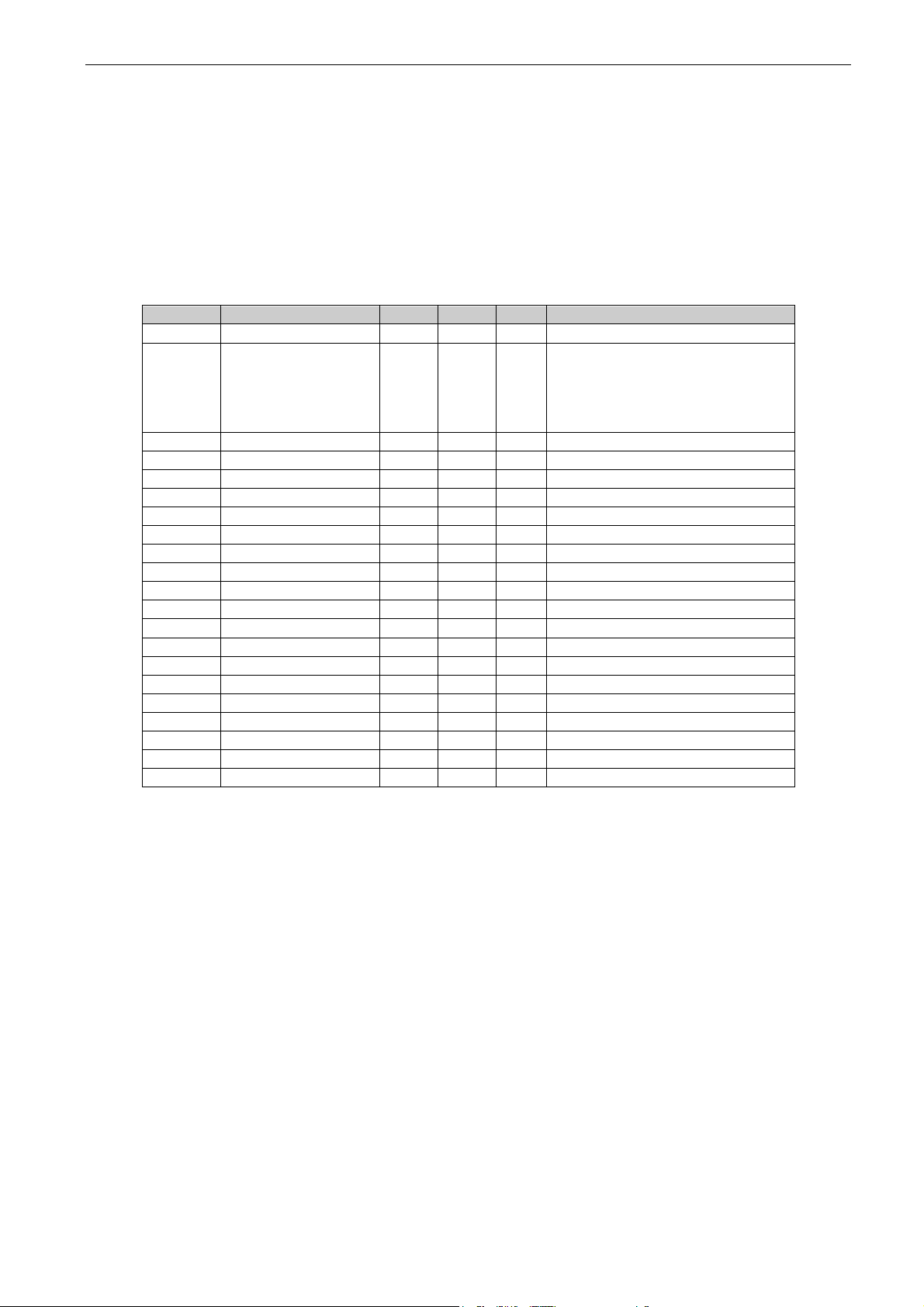
7.1 Basic Parameters (G2.1)
Code
Parameter
Min
Max
Unit
Default
ID
Note
P2.1.1
Mot/Gen Type
0 2 0 650
0 = Synchronous Machine
1 = PM Motor
2 = Asynchronous Motor
P2.1.2
Nominal Voltage
400V:
323V
690V:
446V
400V:
550V
690V:
758V
V
400
110
Set here the nominal voltage of
the generator.
P2.1.3
Nominal Frequency
0
125
Hz
50
1532
P2.1.4
Nominal Current
0.0 A 113 P2.1.5
Nominal Speed
24
20000
rpm
1440
112 P2.1.6
Nominal Cos Phi
0.30
1.00 0.85
120 P2.1.7
Nominal Power
0
32700
kW 0 116 P2..1.8
Magnetization Current
612
P2.1.9
Parallel Generator
0 1 0 1501
0 = Single Generator
1 = Parallel Generator
Activation will set DC Drooping
to 4%.
P2.1.10
Identification
0 8
0
631
0=No action
1=Identification w/o run
2=Identification with run
3=Encoder ID Run
4=Ident All
5=Absolute encoder, locked
rotor
6=U/f and Magn.Current
7=DTC ident.
8=Current Meas. Offset AFE.
NOTE: Set motor control mode
to Freq Control before
identification!
Table 7-1, Basic parameters
Page 36

36 • VACON® arfiff30 Generator
Local contacts: http://drives.danfoss.com/danfoss-drives/local-contacts/
Classified as Business
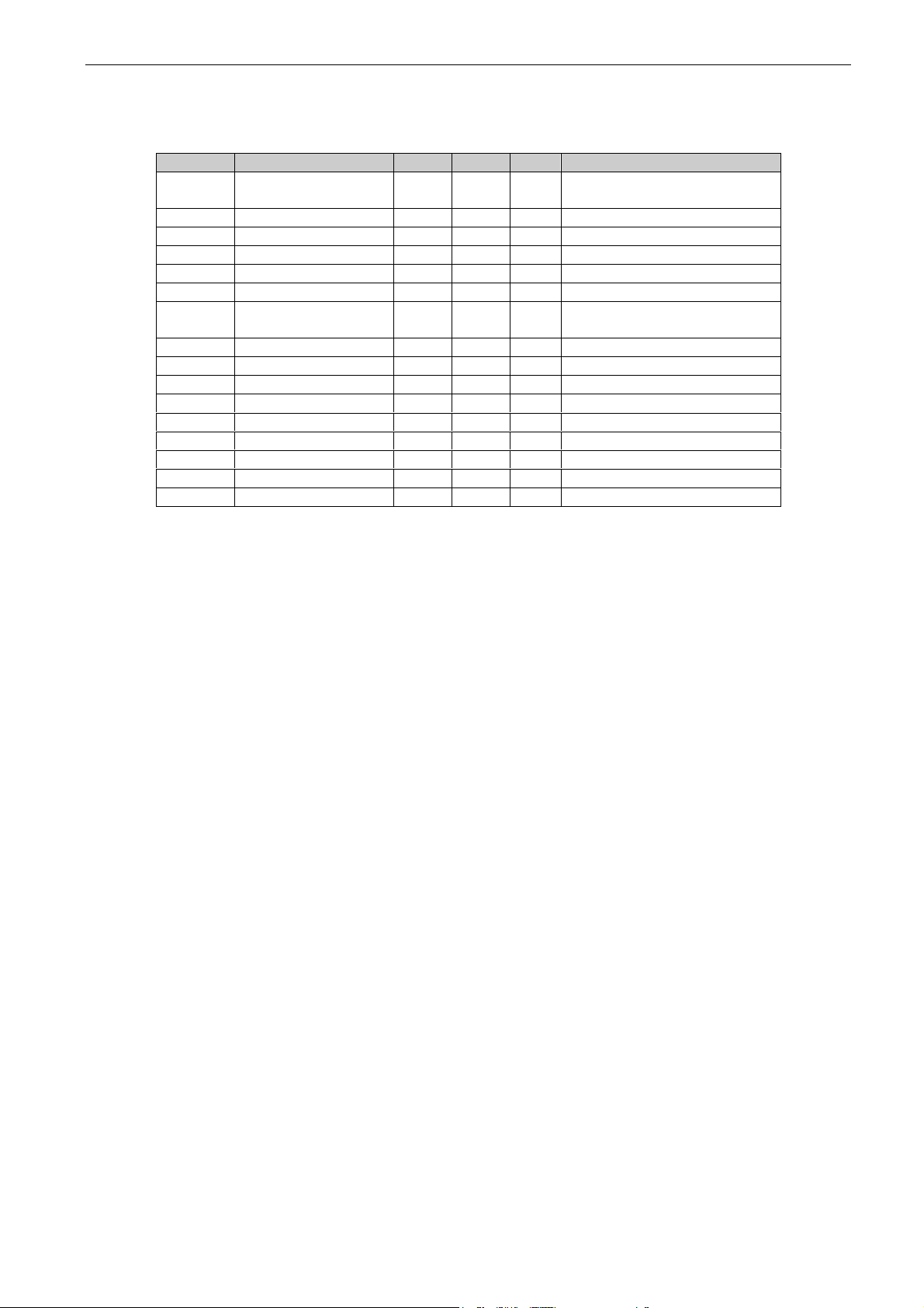
7.2 Reference Handling (G2.2)
7.2.1 PTM handling
Code
Parameter
Min
Max
Unit
Default
ID
Note
P2.2.1.1
Power Take Mode 00
0 4 0 1910
0 = Commissioning
1 = PTO
2 = PTI-BOOST
3 = PTI- 0-Speed
4 = Regen Motor
P2.2.1.2
Power Take Mode 01
0 4 0 1902
0 = Commissioning
1 = PTO
2 = PTI-BOOST
3 = PTI- 0-Speed
4 = Regen Motor
P2.2.1.3
Power Take Mode 10
0 4 0 1903
0 = Commissioning
1 = PTO
2 = PTI-BOOST
3 = PTI- 0-Speed
4 = Regen Motor
P2.2.1.4
Power Take Mode 11
0 4 0 1904
0 = Commissioning
1 = PTO
2 = PTI-BOOST
3 = PTI- 0-Speed
4 = Regen Motor
P2.2.1.5
PTM Stop Time
0.00
30.00 s 3.00
1915
Table 7-2, Power take mode handling
7.2.2 PTO handling
Code
Parameter
Min
Max
Unit
Default
ID
Note
2.2.1.6.1
Torque Select
0 5 0 1931
0 = Speed
1 = Torque
2 = Ramp Out
3 = Min
4 = Max
5 = Window
2.2.1.6.2
Torque Reference
Select
0 6 0 1929
0 = Torque Ref Max
1 = Curve 1
2 = Analogue Input 1
3 = Analogue Input 2
4 = AI1 Joystick
5 = AI2 Joystick
6 = Fieldbus
7 = Curve 2
8 = Curve 3
2.2.1.6.3
Load Share
0.0
400.0 % 100.0
1248
Table 7-3, Power take out handling
Page 37

arfiff30 Generator VACON® • 37
Local contacts: http://drives.danfoss.com/danfoss-drives/local-contacts/
Classified as Business
7.2.3 PTI-Boost handling
Code
Parameter
Min
Max
Unit
Default
ID
Note
2.2.1.7.1
Torque Select
0 5 0 1930
0 = Speed
1 = Torque
2 = Ramp Out
3 = Min
4 = Max
5 = Window
2.2.1.7.2
Torque Reference
Select
0 6 0 1928
0 = Torque Ref Max
1 = Curve 1
2 = Analogue Input 1
3 = Analogue Input 2
4 = AI1 Joystick
5 = AI2 Joystick
6 = Fieldbus
7 = Curve 2
8 = Curve 3
Table 7-4, Power Take in boost handling
7.2.4 PTI 0-Speed
Code
Parameter
Min
Max
Unit
Default
ID
Note
2.2.1.8.1
Torque Select
0 5 0 1933
0 = Speed
1 = Torque
2 = Ramp Out
3 = Min
4 = Max
5 = Window
2.2.1.8.2
Torque Reference
Select
0 6 0 1932
0 = Torque Ref Max
1 = Curve 1
2 = Analogue Input 1
3 = Analogue Input 2
4 = AI1 Joystick
5 = AI2 Joystick
6 = Fieldbus
7 = Curve 2
8 = Curve 3
Table 7-5, Power take in zero speed parameters
7.2.5 Regen Motor Mode
Code
Parameter
Min
Max
Unit
Default
ID
Note
2.2.1.9.1
License Key
0
65535 0
1995
2.2.1.9.2
Reserved
Table 7-6, Regenerative motor mode parameters
Page 38

38 • VACON® arfiff30 Generator
Local contacts: http://drives.danfoss.com/danfoss-drives/local-contacts/
Classified as Business
7.2.6 Commissioning
Code
Parameter
Min
Max
Unit
Default
ID
Note
2.2.1.10.1
MC Mode
0 4 0 1913
0 = AFE
1 = Freq. Control
2 = OL Torque Control
3 = CL Speed Control
4 = CL Torque Control
2.2.1.10.2
DC Control
0 1 0 1914
0 = No
1 = Yes
2.2.1.10.3
Torque Select
0 5 0 1278
0 = Speed
1 = Torque
2 = Ramp Out
3 = Min
4 = Max
5 = Window
2.2.1.10.4
Torque Reference
Select
0 6 1 641
0 = Torque Ref Max
1 = Curve 1
2 = Analogue Input 1
3 = Analogue Input 2
4 = AI1 Joystick
5 = AI2 Joystick
6 = Fieldbus
7 = Curve 2
8 = Curve 3
Table 7-7, Commissioning parameters
7.2.7 DC Voltage Reference Handling
Code
Parameter
Min
Max
Unit
Default
ID
Note
P2.2.2.1
System Nominal AC
400V:
323V
690V:
446V
400V:
550V
690V:
758V
V 0 1201
Keep zero if motor or
generator voltage is same as
grid voltage.
P2.2.2.2
System Nominal DC
0
1500 V 0
1809
P2.2.2.3
DC Voltage Ref.
500V:
105%
690V:
105%
500V:
130%
690V:
115%
%
110.00
1462
DC Voltage reference as % of
Nominal DC Voltage
Nominal DC voltage = 1.35 *
Supply voltage
P2.2.2.4
DC Voltage Drooping
0
100 % 0
620
AFE drooping DC-voltage.
Parallel 3.00%
P2.2.2.5
Reactive Current
Reference
-100
100 % 0
1459
Regenerative reactive
current reference 100,0 =
nominal current.
Positive =Inductive
Negative = Capacitive
P2.2.2.6
DC Voltage Filtering
time
0
15.00 s 0,03
1760
Table 7-8, DC voltage reference handling
Page 39

arfiff30 Generator VACON® • 39
Local contacts: http://drives.danfoss.com/danfoss-drives/local-contacts/
Classified as Business
7.2.8 Speed / Frequency Ref handling
Code
Parameter
Min
Max
Unit
Default
ID
Note
P2.2.3.1
Speed Ref Select
0 5 0 117
0 = Keypad Reference
1 = Analogue Input 1
2 = Analogue Input 2
3 = AI1 Joystick
4 = AI2 Joystick
5 = Fieldbus
P2.2.3.2
Min Frequency
0
125 0
101
P2.2.3.3
Max Frequency
0
125 50
102
Table 7-9, Speed / frequency reference handling
7.2.9 Torque Control
Code
Parameter
Min
Max
Unit
Default
ID
Note
P2.2.4.1
PTI Torq Ref Min
-300.0
300.0 % 0.0
643
P2.2.4.2
PTI Torq Ref Max
-300.0
300.0 % 100.0
642
P2.2.4.3
PTO Torq Ref Min
-300.0
300.0 % 0.0
1926
P2.2.4.4
PTO Torq Ref Max
-300.0
300.0
%
-100.0
1927
P2.2.4.5
TRefRampUpRate
-10
32000
%/s
50,0
1934
P2.2.4.6
TRefRampDownRate
-10
32000
%/s
200,0
1935
Table 7-10, Torque control
7.2.10 Motor Potentiometer reference
Code
Parameter
Min
Max
Unit
Default
ID
Note
P2.2.5.1
Frequency Adjust
Rate
0.001
20.000
Hz/s
0.100
331
P2.2.5.2
Frequency Down
0.1
E.10
DigIN
0.1
417
P2.2.5.3
Frequency Up
0.1
E.10
DigIN
0.1
418
P2.2.5.4
Frequency Max
Adjust
0.00
25.00
Hz
5.00
1558
Table 7-11, Motor potentiometer reference parameters
7.3 Ramp Control (G2.3)
7.3.1 Ramp Control
Code
Parameter
Min
Max
Unit
Default
ID
Note
P2.3.1
Start Function
0 1 1 1274
0 = Ramp Start
1 = Flying Start
P2.3.2
Ramp Time
0.1
3200.0 s 10.0
103 P2.3.3
Ramp Shape
0
100 % 2
500
Table 7-12, Ramp control parameters
Page 40

40 • VACON® arfiff30 Generator
Local contacts: http://drives.danfoss.com/danfoss-drives/local-contacts/
Classified as Business
7.4 Input Signals (G2.4)
7.4.1 Basic settings
Code
Parameter
Min
Max
Unit
Default
ID
Note
P2.4.1.1
Start/Stop Logic
0 2 0 300
0=Start-No Act
1=RPuls-FPuls
2=RPuls-RPuls
P2.4.1.2
Input Inversion
0
65535 4
1091
Inversion control of the
input IO signals.
B0= INV Open Contactor
B1=INV Ext. Fault 1
B2=INV Ext. Fault 2
Table 7-13, Input signal basic parameters
Page 41

arfiff30 Generator VACON® • 41
Local contacts: http://drives.danfoss.com/danfoss-drives/local-contacts/
Classified as Business
7.4.2 Digital Inputs
Code
Parameter
Min
Max
Unit
Default
ID
Note
P2.4.2.1
Start Signal 1
0.1
E.10 A.1
403
This parameter is used to
choose the input for Run
Request signal. When
controlling the AFE from
I/O this signal must be
connected.
P2.4.2.2
Start Signal 2
0.1
E.10 0.1
404
This parameter is used to
choose the input for Stop
Request signal.
P2.4.2.3
Open Contactor
0.1
E.10 0.1
1600
This parameter is used to
choose the input for
Contactor Open signal. The
signal is used to force the
main contactor open and
stop modulating.
P2.4.2.4
MainContFeedBack
0.1
E.10 0.1
1453
AFE contactor feedback
(MCC 1)
P2.4.2.5
Fault Reset
0.1
E.10 A.3
414
Contact closed: All faults
are reset
P2.4.2.6
Ext Fault 1
0.1
E.10 0.1
405
Can be inverted by Input
inversion control.
P2.4.2.7
Ext Fault 2
0.1
E.10 0.2
406
Can be inverted by Input
inversion control.
P2.4.2.8
Run Enable
0.1
E.10 0.2
407
Contact open: Start of
motor disabled
Contact closed: Start of
motor enabled
P2.4.2.9
Cooling Monitor
0.1
E.10 0.2
750
OK input from the cooling
unit
P2.4.2.10
Quick Stop
0.1
E.10 0.2
1213
P2.4.2.11
LCL Temperature
0.1
E.10 0.2
1179
P2.4.2.12
RR Enable
0.1
E.10 0.2
1896
Disables final Run
Command
P2.4.2.13
I/O Control
0.1
E.10 0.1
409 P2.4.2.14
Keypad Control
0.1
E.10 0.1
410 P2.4.2.15
Fieldbus Control
0.1
E.10 0.1
411
P2.4.2.16
Power Take Mode
01
0.1
E.10 0.1
1905
P2.4.2.17
Power Take Mode
10
0.1
E.10 0.1
1906
P2.4.2.18
In Power Lim 1
0.1
E.10 0.1
1917
P2.4.2.19
In Power Lim 2
0.1
E.10 0.1
1918
P2.4.2.20
Out Power Lim 1
0.1
E.10 0.1
1919
P2.4.2.21
Out Power Lim 2
0.1
E.10 0.1
1920
P2.4.2.22
Active synchro
0.1
E.10 0.1
1610
P2.4.2.23
Active Direct
0.1
E.10 0.1
1601
P2.4.2.24
Reset Direct
0.1
E.10 0.1
1612
P2.4.2.25
Parameter set 1/set 2
selection
0.1
E.10 0.1
496
Closed cont.=Set 2 is used
Open cont.=Set 1 is used
P2.4.2.26
Klixon In 1
0.1
E.10
0.2
780
P2.4.2.27
Klixon In 2
0.1
E.10
0.2
781
P2.4.2.28
Input Switch
0.1
E.10
0.2
1209
P2.4.2.29
Ambient Temp
0.1
E.10
0.2
783
Table 7-14, Digital input parameters
Page 42
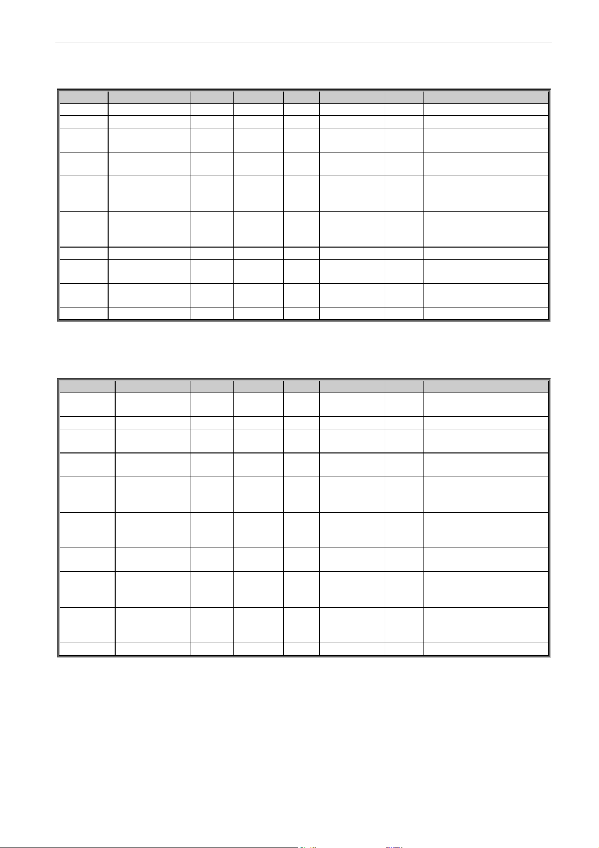
42 • VACON® arfiff30 Generator
Local contacts: http://drives.danfoss.com/danfoss-drives/local-contacts/
Classified as Business
7.4.3 Analogue Input 1
Code
Parameter
Min
Max
Unit
Default
ID
Note
P2.4.3.1
AI1 signal selection
0.1
E.10 A.1
377
P2.4.3.2
AI1 filter time
0.000
32.000 s 0.000
324
P2.4.3.3
AI1 custom
minimum setting
-160.00
160.00 % 0.00
321
4 mA protection active is >
16.00%
P2.4.3.4
AI1 custom
maximum setting
-160.00
160.00
%
100.00
322
P2.4.3.5
AI1 reference
scaling, minimum
value
0
320,00
Hz
0,00
1722
P2.4.3.6
AI1 reference
scaling, maximum
value
0
320,00
Hz
0,00
1723
P2.4.3.7
AI1 signal inversion
0 1 0 387
P2.4.3.8
AI1 scaling,
minimum value
-32000
32000 0
303
P2.4.3.9
AI1 scaling,
maximum value
-32000
32000 0
304
P2.4.3.10
AI1 Controlled ID
0
10000 0
1507
Table 7-15, Analog input 1 parameters
7.4.4 Analogue Input 2
Code
Parameter
Min
Max
Unit
Default
ID
Note
P2.4.4.1
AI2 signal
selection
0.1
E.10 A.2
388
P2.4.4.2
AI2 filter time
0.000
32.000 s 0.000
329
P2.4.4.3
AI2 custom
minimum setting
-160.00
160.00 % 20.00
326
4 mA protection active is >
16.00%
P2.4.4.4
AI2 custom
maximum setting
-160.00
160.00
%
100.00
327
P2.4.4.5
AI2 reference
scaling, minimum
value
0
320,00
Hz
0,00
1724 P2.4.4.6
AI2 reference
scaling,
maximum value
0
320,00
Hz
0,00
1725
P2.4.4.7
AI2 signal
inversion
0 1 0 398
P2.4.4.8
AI2 reference
scaling, minimum
value
-32000
32000 0
393 P2.4.3.9
AI2 reference
scaling,
maximum value
-32000
32000 0
394
P2.4.4.10
AI2 Controlled ID
0
10000 0
1511
Table 7-16, Analog input 2 parameters
Page 43
arfiff30 Generator VACON® • 43
Local contacts: http://drives.danfoss.com/danfoss-drives/local-contacts/
Classified as Business
7.4.5 Analogue Input 3
Code
Parameter
Min
Max
Unit
Default
ID
Note
P2.4.5.1
AI3 signal selection
0.1
E.10 0.1
141
P2.4.5.2
AI3 filter time
0.000
32.000 s 0.000
142
P2.4.5.3
AI3 custom
minimum setting
-160.00
160.00 % 0.00
144
P2.4.5.4
AI3 custom
maximum setting
-160.00
160.00
%
100.00
145
P2.4.5.5
AI3 signal inversion
0 1 0 151
P2.4.5.6
AI3 reference
scaling, minimum
value
-32000
32000 0
1037
P2.4.5.7
AI3 reference
scaling, maximum
value
-32000
32000 0
1038
P2.4.5.8
AI3 Controlled ID
0
10000 0
1509
Table 7-17, Analog input 3 parameters
7.4.6 Analogue Input 4
Code
Parameter
Min
Max
Unit
Default
ID
Note
P2.4.6.1
AI4 signal selection
0.1
E.10 0.1
152
P2.4.6.2
AI4 filter time
0.000
32.000 s 0.000
153
P2.4.6.3
AI4 custom
minimum setting
-160.00
160.00 % 20.00
155
P2.4.6.4
AI4 custom
maximum setting
-160.00
160.00
%
100.00
156
P2.4.6.5
AI4 signal inversion
0 1 0 162
P2.4.6.6
AI4 reference
scaling, minimum
value
-32000
32000 0
1039
P2.4.6.7
AI4 reference
scaling, maximum
value
-32000
32000 0
1040
P2.4.6.8
AI4 Controlled ID
0
10000 0
1510
Table 7-18, Analog input 4 parameters
Page 44

44 • VACON® arfiff30 Generator
Local contacts: http://drives.danfoss.com/danfoss-drives/local-contacts/
Classified as Business
7.5 Output Signals (G2.5)
7.5.1 Dig Out Signals
Code
Parameter
Min
Max
Unit
Default
ID
Note
P2.5.1.1
Main Contactor
Close
0.1
E.10 0.1
1218
AFE contactor, fixed to
Relay output B.2
P2.5.1.2
Main Contactor
Open
0.1
E.10 0.1
1219
Used if pulse control is need
for main breaker.
P2.5.1.3
Ready
0.1
E.10 0.1
432
The AC drive is ready to
operate.
P2.5.1.4
Run
0.1
E.10 0.1
433
The AC drive operates (the
motor is running).
P2.5.1.5
Common Fault
0.1
E.10 0.1
434
A fault trip has occurred.
P2.5.1.6
Fault, Inverted
0.1
E.10 0.1
435
No fault trip has occurred.
P2.5.1.7
At reference
0.1
E.10 0.1
442
The output frequency has
reached the set reference
In AFE when DC-Voltage
level is on setpoint.
P2.5.1.8
OverTemp Warn.
0.1
E.10 0.1
439
The heatsink temperature
exceeds +70 C
P2.5.1.9
Warning
0.1
E.10 0.1
436
General warning signal.
P2.5.1.10
Charge Control
0.1
E.10 0.1
1568
Charge control from start
command
P2.5.1.11
Common Alarm
0.1
E.10 0.1
1684
P2.5.1.12
Ready For Start
0.1
E.10 0.1
1686
No conditions that could
disable starting active
P2.5.1.13
Quick Stop
Active
0.1
E.10 0.1
1687
P2.5.1.14
Fieldbus digital
input 1
0.1
E.10 0.1
455
FB CW B11
P2.5.1.15
FB Dig 1
Parameter
ID0
ID0 0
891
Select parameter to control
P2.5.1.16
Fieldbus digital
input 2
0.1
E.10 0.1
456
FB CW B12
P2.5.1.17
FB Dig 2
Parameter
ID0
ID0 0
892
Select parameter to control
P2.5.1.18
Fieldbus digital
input 3
0.1
E.10 0.1
457
FB CW B13
P2.5.1.19
FB Dig 3
Parameter
ID0
ID0 0
893
Select parameter to control
P2.5.1.20
Fieldbus digital
input 4
0.1
E.10 0.1
169
FB CW B14
P2.5.1.21
FB Dig 4
Parameter
ID0
ID0 0
894
Select parameter to control
P2.5.1.22
Generator
Operation
0.1
E.10 0.1
1916
P2.5.1.23
Bypass CB
0.1
E.10 0.1
1603
P2.5.1.24
Temperature limit
supervision
0.1
E.10 0.1
450
Drive temperature
supervision. See ID354
P2.5.1.25
Encoder 1
supervision
function 1
0.1
E.10 0.1
3505
P2.5.1.25
Encoder 1
supervision
function 1
0.1
E.10 0.1
3506
Table 7-19, Digital output parameters
Page 45
arfiff30 Generator VACON® • 45
Local contacts: http://drives.danfoss.com/danfoss-drives/local-contacts/
Classified as Business
7.5.2 Delayed DO 1
Code
Parameter
Min
Max
Unit
Default
ID
Note
P2.5.2.1
Dig.Out 1 Signal
0.1
E.10 0.1
486
Connect the delayed DO1
signal to the digital output of
your choice with this
parameter.
P2.5.2.2
DO1 Content
0
15 0
312
0=Not used
1=Ready
2=Run
3=Fault
4=Fault inverted
5=FC overheat warning
6=Ext. fault or warning
7=Ref. fault or warning
8=Warning
9=Reverse
10=
11= Start Command given
12= FB DIN2
13= FB DIN3
14=ID.Bit DO
P2.5.2.3
DO1 ON Delay
0.00
320.00 s 0.00
487
0.00 = On delay not in use
P2.5.2.4
DO1 OFF Delay
0.00
320.00 s 0.00
488
0.00 = On delay not in use
P2.5.2.5
ID.Bit Free DO
0.00
2000.00
ID.Bit
0.00
1216
Table 7-20, Delayed digital output 1 parameters
7.5.3 Delayed DO 2
Code
Parameter
Min
Max
Unit
Default
ID
Note
P2.5.3.1
Dig.Out 2 Signal
0.1
E.10 0.1
489
Connect the delayed DO2
signal to the digital output of
your choice with this
parameter.
P2.5.3.2
DO2 Content
0
15 0
490
0=Not used
1=Ready
2=Run
3=Fault
4=Fault inverted
5=FC overheat warning
6=Ext. fault or warning
7=Ref. fault or warning
8=Warning
9=Reverse
10=
11=Start Command given
12= FB DIN2
13=FB DIN3
14=ID.Bit DO
P2.5.3.3
DO2 ON Delay
0.00
320.00 S 0.00
491
0.00 = On delay not in use
P2.5.3.4
DO2 OFF Delay
0.00
320.00 S 0.00
492
0.00 = On delay not in use
P2.5.2.5
ID.Bit Free DO
0.00
2000.00
ID.Bit
0.00
1217
Page 46

46 • VACON® arfiff30 Generator
Local contacts: http://drives.danfoss.com/danfoss-drives/local-contacts/
Classified as Business
Table 7-21, Delayd digital output 2 parameters
Page 47
arfiff30 Generator VACON® • 47
Local contacts: http://drives.danfoss.com/danfoss-drives/local-contacts/
Classified as Business
7.5.4 Analog Output 1
Code
Parameter
Min
Max
Unit
Default
ID
Note
P2.5.4.1
Iout 1 signal
AnOUT:0.1
AnOUT:E.10
AnOUT:A.1
464
Connect the AO1 signal to
the analogue output of your
choice with this parameter.
P2.5.4.2
Iout Content
0
13
1 / O/P
Freq
307 P2.5.4.3
Iout Filter
Time
0
10 s 1
308
0=No filtering
P2.5.4.4
Iout Invert
0 1
0 / No
Inversion
309
0=Not inverted
1=Inverted
P2.5.4.5
Iout
Minimum
0 1
0 / 0 mA
310
0=0 mA
1=4 mA
P2.5.4.6
Iout Scale
10
1000
%
100
311
Percentage multiplier.
Defines output when
content is it maximum value
P2.5.4.7
Iout Offset
-100
100 % 0
375
Add -1000 to 1000% to the
analogue output.
Table 7-22, Analog output 1 parameters
7.5.5 Analog Output 2
Code
Parameter
Min
Max
Unit
Default
ID
Note
P2.5.5.1
Iout 2 signal
AnOUT:0.1
AnOUT:E.10
AnOUT:0.1
471
Connect the AO1 signal to
the analogue output of your
choice with this parameter.
P2.5.5.2
Iout Content
0
13
0 / Not
used
472 P2.5.5.3
Iout Filter
Time
0
10 s 0.02
473
0=No filtering
P2.5.5.4
Iout Invert
0 1
0 / No
Inversion
474
0=Not inverted
1=Inverted
P2.5.5.5
Iout
Minimum
0 1
0 / 0 mA
475
0=0 mA
1=4 mA
P2.5.5.6
Iout Scale
10
1000
%
100
476
Percentage multiplier.
Defines output when
content is it maximum value
P2.5.5.7
Iout Offset
-100
100 % 0
477
Add -1000 to 1000% to the
analogue output.
Table 7-23, Analog output 2 parameters
Page 48

48 • VACON® arfiff30 Generator
Local contacts: http://drives.danfoss.com/danfoss-drives/local-contacts/
Classified as Business
7.5.6 Analog Output 3
Code
Parameter
Min
Max
Unit
Default
ID
Note
P2.5.6.1
Iout 3 signal
AnOUT:0.1
AnOUT:E.10
AnOUT:0.1
478
Connect the AO1 signal to
the analogue output of your
choice with this parameter.
P2.5.6.2
Iout Content
0
13 0
479
P2.5.6.3
Iout Filter
Time
0
10 s 0,02
480
0=No filtering
P2.5.6.4
Iout Invert
0 1
0 / No
Inversion
481
0=Not inverted
1=Inverted
P2.5.6.5
Iout
Minimum
0 1
0 / 0 mA
482
0=0 mA
1=4 mA
P2.5.6.6
Iout Scale
10
1000
%
100
483
Percentage multiplier.
Defines output when
content is it maximum value
P2.5.6.7
Iout Offset
-100
100 % 0
484
Add -1000 to 1000% to the
analogue output.
Table 7-24, Analog output 3 parameters
7.5.7 Options
Code
Parameter
Min
Max
Unit
Default
ID
Note
P2.5.7.1
Output Inversion
0
65535 0
1806
P2.5.7.2
DC Supervision Limit
0
1500 V
1454
P2.5.7.3
MCB At Stop
Command
0 1 0 1685
0=Keep MCB Closed
1=Open MCB
P2.5.7.4
MCB Close Delay
0.00
3.00 0.00
1513
Delay to MCB RO
P2.5.7.5
MCB Close Mode
0 3
0/DC Voltage
1607
0 = DC Voltage
1 = DC or Start command
2 = Start Command.
3 = DC, Start or Pre-Charge
Table 7-25, Output signal options
7.5.8 Supervision limits
Code
Parameter
Min
Max
Unit
Default
ID
Note
P2.5.8.1
Temperature limit
supervision function
0 2 0 354
0 = Not Used
1 = Low limit
2 = High limit.
P2.5.8.2
Temperature
supervision limit
-10
75 C 0
355
P2.5.8.3
Encoder 1 frequency
supervision function 1
0 2 0 3503
0 = Not Used
1 = Low limit
2 = High limit.
P2.5.8.4
Encoder 1 supervision
frequency 1
0,00
320,00
Hz 0 3507
P2.5.8.5
Encoder 1 frequency
supervision function 2
0 2 0 3504
0 = Not Used
1 = Low limit
2 = High limit.
P2.5.8.6
Encoder 1 supervision
frequency 2
0,00
320,00
Hz 0 3508
Table 7-26, Suvervision limits
Page 49

arfiff30 Generator VACON® • 49
Local contacts: http://drives.danfoss.com/danfoss-drives/local-contacts/
Classified as Business
7.6 Limit Settings (G2.6)
7.6.1 Current Limit
Code
Parameter
Min
Max
Unit
Default
ID
Note
P2.6.1.1
Current Limit
0
Varies
A
Varies
107
Total current limit
P2.6.1.2
Output Active
Current Limit
0
300,0 % 150,0
1621
Regen Active Current
P2.6.1.3
Input Active Current
Limit
0
300,0 % 150,0
1622
Regen Active Current
Table 7-27, Current limit parameters
7.6.2 Power Limit
Code
Parameter
Min
Max
Unit
Default
ID
Note
P 2.6.2.1
OutputPowerLim
0
300 % 150,0
1290
P 2.6.2.2
InputPowerLim
0
300 % 150,0
1289
P2.6.2.3
PowerLimIncRate
0
10000
%/s
10
1502
P2.6.2.4
Input power limit
scaling
0 3 0 179
0 = Parameter
1 = Curve 1
2 = Curve 2
3 = Curve 3
P2.6.2.5
Output power limit
scaling
0 3 0 1088
0 = Parameter
1 = Curve 1
2 = Curve 2
3 = Curve 3
P2.6.2.6
In Power Lim 1
0
300 % 50
1921
P2.6.2.7
In Power Lim 2
0
300 % 25
1922
P2.6.2.8
Out Power Lim 1
0
300 % 50
1923
P2.6.2.9
Out Power Lim 2
0
300 % 25
1924
P2.6.2.10
Under Voltage
Power DC Level
0
1200 V 0
1611
P2.6.2.11
Under Voltage
Power Limit
-300.0
300.0 % 0
1613
Table 7-28, Power limit parameters
7.6.3 Frequency Limit
Code
Parameter
Min
Max
Unit
Default
ID
Note
P2.6.3.1
AFE Line Low Trip
Limit
0.00
120.00
Hz
25.00
1717
P2.6.3.2
AFE Line High Trip
Limit
0.00
120.00
Hz
75.00
1716
P2.6.3.3
Neg Freq Limit
-120
0.00
Hz
-0.10
1286
P2.6.3.4
Pos Freq Limit
0
120
Hz
100.00
1285
Table 7-29, Frequency limit parameters
7.6.4 Voltage
Code
Parameter
Min
Max
Unit
Default
ID
Note
P2.6.4.1
Voltage Low Trip
Limit
0.00
320.00 % 0.00
1891
P2.6.4.2
Voltage High Trip
Limit
0.00
320.00 % 150.00
1892
Table 7-30, Voltage parameters
Page 50

50 • VACON® arfiff30 Generator
Local contacts: http://drives.danfoss.com/danfoss-drives/local-contacts/
Classified as Business
7.6.5 DC Voltage
7.6.5.1
Open Loop
Code
Parameter
Min
Max
Unit
Default
ID
Note
P2.6.5.1.1
Over Voltage Kp
0
32767 2000
1468
P2.6.5.1.2
Over Voltage Ki
0
32767 500
1409
P2.6.5.1.3
OverVoltageKpAdd
0
32767 2000
1425
P2.6.5.1.4
Brake chopper
0 3 0 504
P2.6.5.1.5
Brake Chopper Level
5: 605
6: 836
5: 797
6: 1099
V
5: 797
6: 1099
1267
Table 7-31, DC voltage control open loop parameters
7.6.5.2
Closed Loop
Code
Parameter
Min
Max
Unit
Default
ID
Note
P2.6.5.2.1
Over Voltage Kp
0
32000 50
699
P2.6.5.2.2
Over Voltage Ki
0
32000 15
698
P2.6.5.2.3
OverVoltageKpAdd
0
32000 50
697
P2.6.5.2.4
Over Voltage
Control Motoring
Torque Limit
0.0
300.0 % 10.0
1623
P2.6.5.2.5
CL OV On PTI
0 1 1 607
OV Controller on PTI
Operation
0 = Disabled
1 = Enabled
P2.6.5.2.6
CL OV Ref On PTI
83
118 % 118
1528
CL Over Voltage reference
on PTI operation
P2.6.5.2.7
Disable Iq Reset on
Over Voltage
Control
0 1 1 3501
P2.6.5.2.8
Under Voltage
Controller
0 1 0 608
0 = Off
1 = CL: On, OL: Off
P2.6.5.2.9
CL Under Voltage
Reference
0
130 % 65
1567
Table 7-32, DC voltage control closed loop parameters
7.6.6 Torque
Code
Parameter
Min
Max
Unit
Default
ID
Note
P2.6.6.1
Generator Torque
Limit
0.0
300.0 % 120.0
1288
P2.6.6.2
Motoring Torque
Limit
0.0
300.0 % 300.0
1287
P2.6.6.3
TorqLimIncRate
0
10000
%/s
10
1819
P2.6.6.4
Generator Torque
Limit Scaling
0 3 0 1087
0 = Parameter
1 = Curve 1
2 = Curve 2
3 = Curve 3
P2.6.6.5
Motoring Torque
Limit Scaling
0 3 0 485
0 = Parameter
1 = Curve 1
2 = Curve 2
3 = Curve 3
P2.6.6.6
Vdc TorqLimZero
0
1100
Vdc 0 1992
P2.6.6.7
VdcZeroTRampUp
-10
3200
%/s
100,0
1993
Table 7-33, DC voltage control torque parameters
Page 51

arfiff30 Generator VACON® • 51
Local contacts: http://drives.danfoss.com/danfoss-drives/local-contacts/
Classified as Business
7.6.7 Active Current
Code
Parameter
Min
Max
Unit
Default
ID
Note
P2.6.7.1
Active Current Min
Lim
-320,0
320.0 % 0,0
1704
P2.6.7.2
Active Current Max
Lim
-320,0
320.0 % 120,0
1705
Table 7-33, DC voltage control active current parameters
7.7 Flux and DC Current handling CL Settings (G2.7)
Code
Parameter
Min
Max
Unit
Default
Cust
ID
Note
P2.7.1
Magnetizing current at
start
0
IL A 0.00
627 P2.7.2
Magnetizing time at
start
0.0
600.0 s 0.0
628
P2.7.3
Flux Reference
0.0
500.0 % 100.0
1250
Table 7-34, DC voltage control flux and dc current handling
Page 52

52 • VACON® arfiff30 Generator
Local contacts: http://drives.danfoss.com/danfoss-drives/local-contacts/
Classified as Business
7.8 Motor Control (G2.8)
7.8.1 Motor Control Basic Settings
Code
Parameter
Min
Max
Unit
Default
Cust
ID
Note
P2.8.1
Motor control mode
0 2
0 600
0=Open Loop
1=Closed Loop
2=PM Sensorless
Table 7-35, Motor control basic parameters
7.8.2 U/f Settings
Code
Parameter
Min
Max
Unit
Default
Cust
ID
Note
P2.8.2.1
U/f optimisation
0 1
0 109
0=Not used
1=Automatic torque boost
P2.8.2.2
U/f ratio selection
0 3
0 108
0=Linear
1=Squared
2=Programmable
3=Linear with flux optim.
P2.8.2.3
Field weakening point
6.00
320.00
Hz
50.00
602
P2.8.2.4
Voltage at field
weakening point
10.00
200.00
%
100.00
603
n% x Unmot
P2.8.2.5
U/f curve midpoint
frequency
0.00
P2.8.3.3
Hz
50.00
604 P2.8.2.6
U/f curve midpoint
voltage
0.00
100.00
%
100.00
605 P2.8.2.7
Output voltage at zero
frequency
0.00
40.00
%
0.00
606
n% x Unmot
P2.8.2.8
U/f curve midpoint
frequency 2
0.00
P2.8.3.3
Hz
50.00
1592
P2.8.2.9
U/f curve midpoint
voltage 2
0.00
100.00
%
100.00
1593
P2.8.2.10
U/f curve midpoint
frequency 3
0.00
P2.8.3.3
Hz
50.00
1589
P2.8.2.11
U/f curve midpoint
voltage 3
0.00
100.00
%
100.00
1591
P2.8.2.12
Field weakening point
2
6.00
320.00
Hz
50.00
1596
P2.8.2.13
Voltage at field
weakening point 2
10.00
200.00
%
100.00
1597
Table 7-36, U/f settings
Page 53

arfiff30 Generator VACON® • 53
Local contacts: http://drives.danfoss.com/danfoss-drives/local-contacts/
Classified as Business
7.8.2.1
Closed Loop Control Settings
Code
Parameter
Min
Max
Unit
Default
Cust
ID
Note
P2.8.3.1
Current control
P gain
0.00
100.00
%
40,00
617
P2.8.3.2
Current control
I Time
0.0
3200.0
ms
1.5
657
P2.8.3.3
Slip adjust
0
500 % 75
619
P2.8.3.4
Speed Error Filter TC
0
1000
ms 0
1311
P2.8.3.5
Encoder filter time
0
1000
ms 0
618
P2.8.3.6
SC Torque Chain
Select
0
65535 0
1557
P2.8.3.7
Encoder Selection
0 2
0
1595
0,1=Encoder Input 1
2=Encoder Input 2
Table 7-37, Motor control closed loop settings
7.8.3 PMSM Control settings
Code
Parameter
Min
Max
Unit
Default
Cust
ID
Note
P2.8.4.1
PMSM Shaft
Position
0
65535 0
649
P2.8.4.2
Start Angle
Identification mode
0
10 0
1691
0=Automatic
1=Forced
2=After Power Up
3=Disabled
P2.8.4.3
Start Angle
Identification DC
Current
0.0
150.0 % 0.0
1756
P2.8.4.4
Polarity Pulse
Current
-10.0
200.0 % 0.0
1566
P2.8.4.5
Start Angle ID Time
0
32000
ms
0
1755
P2.8.4.6
I/f Current
0.0
150.0
%
50.0
1693
P2.8.4.7
I/f Control Limit
0.0
300.0
%
10.0
1790
P2.8.4.8
Flux Current Kp
0
32000 500
651
P2.8.4.9
Flux Current Ti
0
1000
ms
5
652
P2.8.4.10
External Id Ref
-100.0
100.0 0.0
1730
P2.8.4.11
Lsd Voltage Drop
-32000
32000 0
1757
P2.8.4.12
Lsq Voltage Drop
-32000
32000 0
1758
P2.8.4.13
I/f Current 2
0,0
150,0 % 0,0
1694
P2.8.4.14
I/f Control Limit 2
0,0
300,0 % 0,0
1791
P2.8.4.15
Current Control Kp
D
0,00
320,00
%
0,00
1761
P2.8.4.16
Voltage Margin
0,0
120,0
%
100,0
1762
P2.8.4.17
Enc ID Run Mode
0 2
0
680
Table 7-38, PMSM control settings
Page 54
54 • VACON® arfiff30 Generator
Local contacts: http://drives.danfoss.com/danfoss-drives/local-contacts/
Classified as Business
7.8.4 Stabilators
Code
Parameter
Min
Max
Unit
Default
Cust
ID
Note
P2.8.5.1
Torque Stabilator
Damping
0
1000 800
1413
With PMSM use 980
P2.8.5.2
Torque Stabilator Gain
0
1000 100
1412
P2.8.5.3
Torque Stabilator Gain
in FWP
0
1000 50
1414
P2.8.5.4
Torque Stabilator Limit
0
1500 150
1720
P2.8.5.5
Flux Circle Stabilator
Gain
0
32767
10000
1550
P2.8.5.6
Flux Stabilator Gain
0
32000 500
1797
P2.8.5.6
Flux Circle Stabilator
TC
0
32700 900
1551
P2.8.5.8
Flux Stab Coeff
-30000
30000 1796
P2.8.5.9
Voltage Stabilator Gain
0
100.0 % 10.0
1738
P2.8.5.10
Voltage Stabilator TC
0
1000 900
1552
P2.8.5.11
Voltage Stabilator Limit
0
320.00
Hz
1.50
1553
Table 7-39, Stabilator parameters
Page 55

arfiff30 Generator VACON® • 55
Local contacts: http://drives.danfoss.com/danfoss-drives/local-contacts/
Classified as Business
7.8.5 Identification parameters
Code
Parameter
Min
Max
Unit
Default
Cust
ID
Note
P2.8.6.1
Flux 10%
0
2500 % 10
1355 P2.8.6.2
Flux 20%
0
2500 % 20
1356 P2.8.6.3
Flux 30%
0
2500 % 30
1357 P2.8.6.4
Flux 40%
0
2500 % 40
1358 P2.8.6.5
Flux 50%
0
2500 % 50
1359 P2.8.6.6
Flux 60%
0
2500 % 60
1360 P2.8.6.7
Flux 70%
0
2500 % 70
1361 P2.8.6.8
Flux 80%
0
2500 % 80
1362 P2.8.6.9
Flux 90%
0
2500 % 90
1363 P2.8.6.10
Flux 100%
0
2500 % 100
1364 P2.8.6.11
Flux 110%
0
2500 % 110
1365 P2.8.6.12
Flux 120%
0
2500 % 120
1366 P2.8.6.13
Flux 130%
0
2500 % 130
1367 P2.8.6.14
Flux 140%
0
2500 % 140
1368 P2.8.6.15
Flux 150%
0
2500 % 150
1369 P2.8.6.16
Rs voltage drop
0
30000
Varies
662
P2.8.6.17
Ir add zero point
voltage
0
30000
Varies
664
P2.8.6.18
Ir add motoring
scale
0
30000
Varies
667
P2.8.6.19
Ir add generator
scale
0
30000
Varies
665
P2.8.6.20
Ls Voltage Dropp
0
3000 0
673
P2.8.6.21
Motor BEM
Voltage
0.00
320.00 % 0
674
P2.8.6.22
Iu Offset
-32000
32000 0
668 P2.8.6.23
Iv Offset
-32000
32000 0
669 P2.8.6.24
Iw Offset
-32000
32000 0
670 P2.8.6.25
Estimator Kp
0
32000
1781 P2.8.6.26
Estimator Ki
400
1782 P2.8.6.27
Voltage Dropp
0
2000 % 671 P2.8.6.28
ID Run Curr. Kp
695 P2.8.6.29
FluxSaturatRatio
682 P2.8.6.30
T:Identification
0
65535 1
3520 P2.8.6.31
T:IdentOptions
0
65535 3
3521
Table 7-40. Identification parameters
7.8.6 Tuning parameters
Code
Parameter
Min
Max
Unit
Default
Cust
ID
Note
P2.8.7.1
Voltage Corr. Kp
0.000
32.000
0.100
1783
P2.8.7.2
Voltage Corr. Ki
0
32000
5000
1784
Table 7-41, Tuning parameters
Page 56

56 • VACON® arfiff30 Generator
Local contacts: http://drives.danfoss.com/danfoss-drives/local-contacts/
Classified as Business
7.8.7 Flying Start Tuning parameters
Code
Parameter
Min
Max
Unit
Default
Cust
ID
Note
P2.8.8.1
Flying Start Options
0
65535 33
1770
P2.8.8.2
AC magnetization
Current
0.0
150.0 % 70.0
1810
P2.8.8.3
AC Scanning Time
0
32000
ms
900
1811
P2.8.8.4
DC magnetization
Current
0.0
150.0 % 100.0
1812
P2.8.8.5
Flux Build Torque
0.0
300.0 10.0
1814
P2.8.8.6
Flux Build Time
0
10000 300
1813
P2.8.8.7
Magnetization
Phases
0
20 10
1815
P2.8.8.8
FlyStartPhs1Time
0
1000
ms
1718
Table 7-42, Flying start parameters
7.9 Speed Control (G2.9)
Code
Parameter
Min
Max
Unit
Default
Cust
ID
Note
P2.9.1
Speed controller
P gain (open loop)
0
32767
3000
637 P2.9.2
Speed controller
I gain (open loop)
0
32767 300
638
P2.9.3
Speed control P gain
(Closed Loop)
0
1000 5 613
P2.9.4
Speed control I time
(Closed Loop)
-
32000
32000
ms
100
614
Negative value uses 0.1 ms
format instead of 1 ms
P2.9.5
Load Drooping
0
100 % 0,00
647
Table 7-43. Speed control open loop settings
Page 57

arfiff30 Generator VACON® • 57
Local contacts: http://drives.danfoss.com/danfoss-drives/local-contacts/
Classified as Business
7.10 Drive Control (G2.10)
Code
Parameter
Min
Max
Unit
Default
ID
Note
P 2.10.1
Switching Freq
3.6 6 kHz
3.6
601
P 2.10.2
AFE Options 1
0
65535 544
1463
P 2.10.3
AFE Options 2
0
65535 0
1464
Reserved for future use
P 2.10.4
Start Delay
0.00
3200 s 1.0
1500
P 2.10.5
AdvancedOptions1
0
65535 0
1560
P 2.10.6
AdvancedOptions2
0
65535 0
1561
P 2.10.7
AdvancedOptions3
0
65535 0
1562
P 2.10.8
AdvancedOptions4
0
65535 0
1563
P 2.10.9
AdvancedOptions5
0
65535 0
1564
P 2. 0.10
AdvancedOptions6
0
65535 0
1565
P 2.10.11
AdvancedOptions7
0
65535 0
1594
P 2.10.12
Modulator Type
0 4 1 1516
P 2.10.13
Control Options 1
0
65535 1024
1707
P2.10.14
Control Options 2
0
65535 0
1798
P2.10.15
Synch Kp Start
0
32000 4000
1698
P2.10.16
Capacitor Size
0.0
100.0 6.3
1460
P2.10.17
Inductor Size
0.0
100.0 15.5
1461
P2.10.18
Operation Time
0 1855
P2.10.19
Active Current Kp
400
1455
P2.10.20
Active Current Ti
15
1456
P2.10.21
Restart Delay
0
32000 1000
672
P2.10.22
DC Voltage Kp
1451
P2.10.23
DC Voltage Ti
1452
P2.10.24
Synch Kp
1457
P2.10.25
Synch Ti
1458
P2.10.26
ModIndexLimit
0
150 %
1936
P2.10.27
DCLinkMeasCalib
-2,00
2,00 %
549
Table 7-45, Drive control parameters
7.11 Master Follower (G2.11)
Code
Parameter
Min
Max
Unit
Default
ID
Note
P2.11.1
MF Mode
0 6 0 1324
P2.11.2
Follower Phase Shift
-360
360
Dec
0
1518
P2.11.3
DC Voltage Balance
Gain
0
1000
1519
P2.11.4
Reserved
Table 7-46, Master follower parameters
Page 58
58 • VACON® arfiff30 Generator
Local contacts: http://drives.danfoss.com/danfoss-drives/local-contacts/
Classified as Business
7.12 Protection (G 2.12)
7.12.1 General
Code
Parameter
Min
Max
Unit
Default
ID
Note
P2.12.1.1
Thermistor Faul
Response
0 3
2 / Fault
732
0=No response
1=Warning
2=Fault,stop acc. StopMode
3=Fault,stop by coasting
P2.12.1.2
LCL Over
Temperature
0 3 2 1505
P2.12.1.3
Max Charge Time
0.00
30.00 s 5.00
1522
Charging time limit when
drive charging options are
used.
P2.12.1.4
MCC At Fault
0 1 0 1699
0= No Action
1=Open MCC
P2.12.1.5
Quick Stop Responce
0 2
1 / Warning
1543
0=No indication
1=Warning
2=Fault
P2.12.1.6
Reac Error Trip Limit
%
7.5
1759
P2.12.1.7
MCC Fault Delay
s
3.50
1521
P2.12.1.8
Line Phase
Supervision
0 / No Action
702
0=No Action
1=Warning
2=Fault
P2.12.1.9
4 mA Fault Response
0 2
0 / No Action
700
0=No Action
1=Warning
2=Fault
P2.12.1.10
Response to encoder
fault
1
3 2
1353
1=Warning
2=Fault
3=Warning: To Open Loop
P2.12.1.11
FaultWarnIndicat
0
2 1
1940
0=Static
1=Toggle
2=Marine
P2.12.1.12
Run Enable Indication
0
2 1
1177
0=No Action
1=Warning
2=Fault
Table 7-47, Protections parameters
Page 59

arfiff30 Generator VACON® • 59
Local contacts: http://drives.danfoss.com/danfoss-drives/local-contacts/
Classified as Business
7.12.2 Temperature Board parameters
Code
Parameter
Min
Max
Unit
Default
ID
Note
P2.12.2.1
PT100 Channels
0 5 0 739
0= Not used (ID Write)
1= PT100 input 1
2= PT100 input 1 & 2
3= PT100 input 1 & 2 & 3
2= PT100 input 2 & 3
3= PT100 input 3
P2.12.2.2
PT100 FaultResponse
0 3
2 / Fault
740
0= No response
1= Warning
2= Fault,stop acc. to 2.4.7
3= Fault,stop by coasting
P2.12.2.3
PT100 Warn.Limit
-30
200
°C
120
741
P2.12.2.4
PT100 Fault Lim.
-30
200
°C
130
742
P2.12.2.5
PT100 2 Response
0 3
2 / Fault
766
0= No response
1= Warning
2= Fault,stop acc. to 2.4.7
3= Fault,stop by coasting
P2.12.2.6
PT100 2 Channels
0 5 0 743
P2.12.2.7
PT100 2 WarnLim
-30
200
°C
120
745
P2.12.2.8
PT100 2 FaultLim
-30
200
°C
130
746
P2.12.2.9.1
Channel 1B Warn
-30,0
200,0
Cº
0,0
764
P2.12.2.9.2
Channel 1B Fault
-30,0
200,0
Cº
0,0
765
P2.12.2.9.3
Channel 1C Warn
-30,0
200,0
Cº
0,0
768
P2.12.2.9.4
Channel 1C Fault
-30,0
200,0
Cº
0,0
769
P2.12.2.9.5
Channel 2B Warn
-30,0
200,0
Cº
0,0
770
P2.12.2.9.6
Channel 2B Fault
-30,0
200,0
Cº
0,0
771
P2.12.2.9.7
Channel 2C Warn
-30,0
200,0
Cº
0,0
772
P2.12.2.9.8
Channel 2C Fault
-30,0
200,0
Cº
0,0
773
Table 7-48, PT-100 parameters
7.12.3 Earth fault
Code
Parameter
Min
Max
Unit
Default
ID
Note
P2.12.3.1
EarthFlt Response
2 5
2 / Fault
1544
P2.12.3.2
EarthFaultLevel
0
100 % 50
1333
Table 7-49, Earth fault parameters
7.12.4 External Fault
Code
Parameter
Min
Max
Unit
Default
ID
Note
P2.12.4.1
External Fault 1
0 3
2 / Fault
701
P2.12.4.2
External Fault 2
0 3
1 / Warning
1504
P2.12.4.3
External Fault Delay
0.00
320.00 s 0.00
1506
Table 7-50, External fault parameters
Page 60
60 • VACON® arfiff30 Generator
Local contacts: http://drives.danfoss.com/danfoss-drives/local-contacts/
Classified as Business
7.12.5 Generator Voltage
Code
Parameter
Min
Max
Unit
Default
ID
Note
P2.12.5.1
Voltage Error Response
0 2 0 1880
P2.12.5.2
Voltage Low Warning
Limit
0.00
320.00 % 90.00
1893
P2.12.5.3
Voltage Low Trip Limit
0.00
320.00 % 80.00
1899
P2.12.5.4
Voltage High Warning
Limit
0.00
320.00 % 110.00
1895
P2.12.5.5
Voltage High Trip Limit
0.00
320.00 % 120.00
1799
P2.12.5.6
Voltage Trip Delay
0.00
320.00 s 0.50
1898
Table 7-51, Generator voltage parameters
7.12.6 Generator Frequency
Code
Parameter
Min
Max
Unit
Default
ID
Note
P2.12.6.1
Frequency Error Response
0 2 0 1981
P2.12.6.2
Freq. low Warning Limit
0.00
320.00
%
95.00
1780
P2.12.6.3
Freq. Low Trip Limit
0.00
320.00
%
90.00
1788
P2.12.6.4
Freq. High Warning Limit
0.00
320.00
%
105.00
1786
P2.12.6.5
Freq. High Trip Limit
0.00
320.00
%
110.00
1787
P2.12.6.6
Freq. Trip Delay
0.00
320.00
s
0.50
1785
Table 7-52, Generator frequency parameters
7.12.7 Motor thermal protections
Code
Parameter
Min
Max
Unit
Default
Cust
ID
Note
2.12.7.1
Thermal protection
of the motor
0 3
2 704
0=No response
1=Warning
2=Fault,stop acc. to 2.3.2
3=Fault,stop by coasting
2.12.7.2
Motor ambient
temperature factor
100.0
100.0 % 0.0
705
2.12.7.3
Motor cooling factor
at zero speed
0.0
150.0 % 40.0
706 2.12.7.4
Motor thermal time
constant
1
200
min
45
707
2.12.7.5
Motor duty cycle
0
100 % 100
708
2.12.7.6
Over Load
Response
0 2
1
1838
0=No response
1=Warning
2=Fault
2.12.7.7
Over Load Signal
0 2
0
1837
0=Not Used
1=Current
2=Torque
3=Power
2.12.7.8
Over Load
Maximum Input
0.0
300.0 % 150.0
1839
2.12.7.9
Over Load
maximum Step
0
10000 200
1840
Table 7-53. Motor thermal protection parameters
Page 61
arfiff30 Generator VACON® • 61
Local contacts: http://drives.danfoss.com/danfoss-drives/local-contacts/
Classified as Business
7.12.8 Fieldbus protection
Code
Parameter
Min
Max
Unit
Default
Cust
ID
Note
P2.12.8.1
FB Fault response
Slot D
0 2 2
733
0=No Action
1=Warning
2= Fault
P2.12.8.2
FB Fault response
Slot E
0 2 2
761
0=No Action
1=Warning
2= Fault
P2.12.8.3
FB Watchdog Delay
0.00
30.00 s 0.00
1354
Delay when WD pulse is
missing. 0.00 s = Disabled
Table 7-54. Fieldbus protection parameters
7.12.9 Cooling Monitoring
Code
Parameter
Min
Max
Unit
Default
ID
Note
P2.12.9.1
Cooling Flt. Delay
0 7 s 2 751
P2.12.9.1
Cooling Fault Response
0 3 2 762
0= No Action, Warning
1= Warning, Warning
2= Warning, Fault
3= No Action, Fault
Table 7-55, Cooling monitoring
7.12.10 Options
Code
Parameter
Min
Max
Unit
Default
ID
Note
P2.12.9
Disable Stoplock
0 1
0/No
1086
P2.12.10
Fault Simulation
0
65535 0
1569
P2.12.11
Reset Datalogger
-1 1 0 1857
-1 = Blocked
0 = No
1 = Yes
Table 7-55, Protection options
Page 62
62 • VACON® arfiff30 Generator
Local contacts: http://drives.danfoss.com/danfoss-drives/local-contacts/
Classified as Business
7.13 Fieldbus (G 2.13)
Code
Parameter
Min
Max
Unit
Default
ID
Note
P2.13.1
FB Actual ID
0
10000 7
1851
P2.13.2
FB Data Out1 Sel
0
10000
1104
852
P2.13.3
FB Data Out2 Sel
0
10000
1508
853
P2.13.4
FB Data Out3 Sel
0
10000
1172
854
P2.13.5
FB Data Out4 Sel
0
10000
1173
855
P2.13.6
FB Data Out5 Sel
0
10000 56
856
P2.13.7
FB Data Out6 Sel
0
10000
1174
857
P2.13.8
FB Data Out7 Sel
0
10000
1125
858
P2.13.9
FB Data Out8 Sel
0
10000
1157
859
P2.13.10
FB Data Out9 Sel
0
10000 0
558
Visible with correct hw and sw
P2.13.11
FB Data Out10 Sel
0
10000 0
559
Visible with correct hw and sw
P2.13.12
FB Data Out11 Sel
0
10000 0
560
Visible with correct hw and sw
P2.13.13
FB Data Out12 Sel
0
10000 0
561
Visible with correct hw and sw
P2.13.14
FB Data Out13 Sel
0
10000 0
562
Visible with correct hw and sw
P2.13.15
FB Data Out14 Sel
0
10000 0
563
Visible with correct hw and sw
P2.13.16
FB Data Out15 Sel
0
10000 0
564
Visible with correct hw and sw
P2.13.17
FB Data Out16 Sel
0
10000 0
565
Visible with correct hw and sw
P2.13.18
FB Reference Sel
0
10000 0
1850
P2.13.19
FB Data In 1 Sel
0
10000 0
876
P2.13.20
FB Data In 2 Sel
0
10000 0
877
P2.13.21
FB Data In 3 Sel
0
10000 0
878
P2.13.22
FB Data In 4 Sel
0
10000 0
879
P2.13.23
FB Data In 5 Sel
0
10000 0
880
P2.13.24
FB Data In 6 Sel
0
10000 0
881
P2.13.25
FB Data In 7 Sel
0
10000 0
882
P2.13.26
FB Data In 8 Sel
0
10000 0
883
P2.13.27
FB Data In 9 Sel
0
10000 0
550
Visible with correct hw and sw
P2.13.28
FB Data In 10 Sel
0
10000 0
551
Visible with correct hw and sw
P2.13.29
FB Data In 11 Sel
0
10000 0
552
Visible with correct hw and sw
P2.13.30
FB Data In 12 Sel
0
10000 0
553
Visible with correct hw and sw
P2.13.31
FB Data In 13 Sel
0
10000 0
554
Visible with correct hw and sw
P2.13.32
FB Data In 14 Sel
0
10000 0
555
Visible with correct hw and sw
P2.13.33
FB Data In 15 Sel
0
10000 0
556
Visible with correct hw and sw
P2.13.34
FB Data In 16 Sel
0
10000 0
557
Visible with correct hw and sw
P2.13.35
GSW Data
0
10000 0
897
P2.13.36
Control Slot
Selector
0
Varies 0
1440
0=Not Sel., 4=Slot D
5=Slot E, 6=Slot D Fast
7=Slot E Fast, 8=Slot D 16,
9=Slot E 16
Note: 6-9 visible with correct
hw and sw.
P2.13.37
State Machine
1 2 2 896
0=Basic
1=Standard
2=Generator
P2.13.38
SW B11 ID.Bit
0.00
2000.00
0.00
1912
P2.13.39
SW B12 ID.Bit
0.00
2000.00
0.00
1908
P2.13.40
SW B13 ID.Bit
0.00
2000.00
0.00
1909
P2.13.41
SW B14 ID.Bit
0.00
2000.00
0.00
1911
Table 7-56, Fieldbus parameters
Page 63
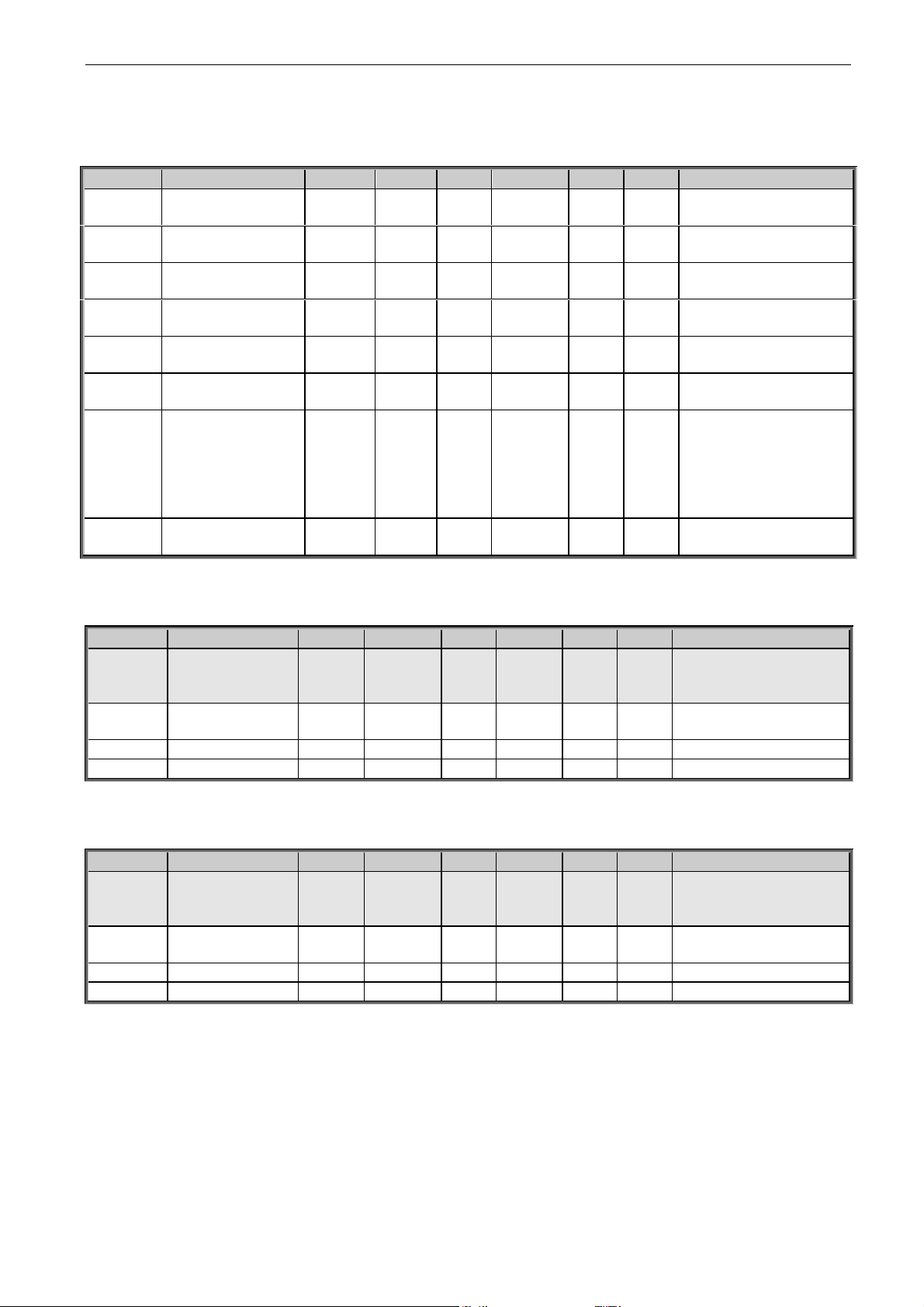
arfiff30 Generator VACON® • 63
Local contacts: http://drives.danfoss.com/danfoss-drives/local-contacts/
Classified as Business
7.14 ID Control Functions (G2.14)
7.14.1 Value Control
Code
Parameter
Min
Max
Unit
Default
Cust
ID
Note
P2.14.1.1
Control Input Signal
ID
0
10000
ID
0
1580
P2.14.1.2
Control Input Off
Limit
-32000
32000 0
1581
P2.14.1.3
Control Input On
Limit
-32000
32000 0
1582
P2.14.1.4
Control Output Off
Value
-32000
32000 0
1583
P2.14.1.5
Control Output On
Value
-32000
32000 0
1584
P2.14.1.6
Control Output Signal
ID
0
10000
ID
0
1585
P2.14.1.7
Control Mode
0 5
0
1590
0=SR ABS
1=Scale ABS
2=Scale INV ABS
3=SR
4=Scale
5=Scale INV
P2.14.1.8
Control Output
Filtering rime
0.000
32.000
s
0.000
1721
Table 7-57, Power reference input signal selection
7.14.2 DIN ID Control 1
Code
Parameter
Min
Max
Unit
Default
Cust
ID
Note
P2.14.2.1
ID Control DIN
0.1
E.10
0.1
1570
Slot . Board input No.
If 0.1 ID61 can be
controlled from FB
P2.14.2.2
Controlled ID
0
10000
ID
0 1571
Select ID that is
controlled by digital input
P2.14.2.3
False value
-32000
32000 0 1572
Value when DI is low
P2.14.2.4
True value
-32000
32000 0 1573
Value when DI is high
Table 7-58, Digital input ID control 1 parameters
7.14.3 DIN ID Control 2
Code
Parameter
Min
Max
Unit
Default
Cust
ID
Note
P2.14.3.1
ID Control DIN
0.1
E.10
0.1
1574
Slot . Board input No.
If 0.1 ID61 can be
controlled from FB
P2.14.3.2
Controlled ID
0
10000
ID
0 1575
Select ID that is
controlled by digital input
P2.14.3.3
False value
-32000
32000 0 1576
Value when DI is low
P2.14.3.4
True value
-32000
32000 0 1577
Value when DI is high
Table 7-59, Digital input ID Control 2 parameters
Page 64

64 • VACON® arfiff30 Generator
Local contacts: http://drives.danfoss.com/danfoss-drives/local-contacts/
Classified as Business
7.14.4 DIN ID Control 3
Code
Parameter
Min
Max
Unit
Default
Cust
ID
Note
P2.14.4.1
ID Control DIN
0.1
E.10
0.1
1578
Slot . Board input No.
If 0.1 ID61 can be
controlled from FB
P2.14.4.2
Controlled ID
0
10000
ID
0 1579
Select ID that is
controlled by digital input
P2.14.4.3
False value
-32000
32000 0 1587
Value when DI is low
P2.14.4.4
True value
-32000
32000 0 1588
Value when DI is high
Table 7-60, Digital input ID Control 3 parameters
7.15 Curve 1 definition (G2.15)
Code
Parameter
Min
Max
Unit
Default
Cust
ID
Note
P2.15.1
0% Speed
-320
320 %
1626 P2.15.2
5% Speed
-320
320 %
1627 P2.15.3
10% Speed
-320
320 %
1628 P2.15.4
15% Speed
-320
320 %
1629 P2.15.5
20% Speed
-320
320 %
1630 P2.15.6
25% Speed
-320
320 %
1631 P2.15.7
30% Speed
-320
320 %
1632 P2.15.8
35% Speed
-320
320 %
1633 P2.15.9
40% Speed
-320
320 %
1634 P2.15.10
45% Speed
-320
320 %
1635 P2.15.11
50% Speed
-320
320 %
1636 P2.15.12
55% Speed
-320
320 %
1637 P2.15.13
60% Speed
-320
320 %
1638 P2.15.14
65% Speed
-320
320 %
1639 P2.15.15
70% Speed
-320
320 %
1640 P2.15.16
75% Speed
-320
320 %
1641 P2.15.17
80% Speed
-320
320 %
1642 P2.15.18
85% Speed
-320
320 %
1643 P2.15.19
90% Speed
-320
320 %
1644 P2.15.20
95% Speed
-320
320 %
1645 P2.15.21
100% Speed
-320
320 %
1646 P2.15.22
105% Speed
-320
320 %
1647 P2.15.23
110% Speed
-320
320 %
1648 P2.15.24
115% Speed
-320
320 %
1649 P2.15.25
120% Speed
-320
320 %
1651
Table 7-61, Curve 1 definition parameters
Page 65
arfiff30 Generator VACON® • 65
Local contacts: http://drives.danfoss.com/danfoss-drives/local-contacts/
Classified as Business
7.16 Curve 2 definition (G2.16)
Code
Parameter
Min
Max
Unit
Default
Cust
ID
Note
P2.16.1
0% Speed
-320
320 %
2001 P2.16.2
5% Speed
-320
320 %
2002 P2.16.3
10% Speed
-320
320 %
2003 P2.16.4
15% Speed
-320
320 %
2004 P2.16.5
20% Speed
-320
320 %
2005 P2.16.6
25% Speed
-320
320 %
2006 P2.16.7
30% Speed
-320
320 %
2007 P2.16.8
35% Speed
-320
320 %
2008 P2.16.9
40% Speed
-320
320 %
2009
P2.16.10
45% Speed
-320
320 %
2010
P2.16.11
50% Speed
-320
320 %
2011 P2.16.12
55% Speed
-320
320 %
2012 P2.16.13
60% Speed
-320
320 %
2013 P2.16.14
65% Speed
-320
320 %
2014 P2.16.15
70% Speed
-320
320 %
2015 P2.16.16
75% Speed
-320
320 %
2016 P2.16.17
80% Speed
-320
320 %
2017 P2.16.18
85% Speed
-320
320 %
2018 P2.16.19
90% Speed
-320
320 %
2019 P2.16.20
95% Speed
-320
320 %
2020 P2.16.21
100% Speed
-320
320 %
2021 P2.16.22
105% Speed
-320
320 %
2022 P2.16.23
110% Speed
-320
320 %
2023 P2.16.24
115% Speed
-320
320 %
2024 P2.16.25
120% Speed
-320
320 %
2025
Table 7-62, Curve 2 definition parameters
Page 66

66 • VACON® arfiff30 Generator
Local contacts: http://drives.danfoss.com/danfoss-drives/local-contacts/
Classified as Business
7.17 Curve 3 definition (G2.17)
Code
Parameter
Min
Max
Unit
Default
Cust
ID
Note
P2.17.1
0% Speed
-320
320 %
2030 P2.17.2
5% Speed
-320
320 %
2031 P2.17.3
10% Speed
-320
320 %
2032 P2.17.4
15% Speed
-320
320 %
2033 P2.17.5
20% Speed
-320
320 %
2034 P2.17.6
25% Speed
-320
320 %
2035 P2.17.7
30% Speed
-320
320 %
2036 P2.17.8
35% Speed
-320
320 %
2037 P2.17.9
40% Speed
-320
320 %
2038 P2.17.10
45% Speed
-320
320 %
2039 P2.17.11
50% Speed
-320
320 %
2040 P2.17.12
55% Speed
-320
320 %
2041 P2.17.13
60% Speed
-320
320 %
2042 P2.17.14
65% Speed
-320
320 %
2043 P2.17.15
70% Speed
-320
320 %
2044 P2.17.16
75% Speed
-320
320 %
2045
P2.17.17
80% Speed
-320
320 %
2046
P2.17.18
85% Speed
-320
320 %
2047 P2.17.19
90% Speed
-320
320 %
2048 P2.17.20
95% Speed
-320
320 %
2049 P2.17.21
100% Speed
-320
320 %
2050 P2.17.22
105% Speed
-320
320 %
2051 P2.17.23
110% Speed
-320
320 %
2052 P2.17.24
115% Speed
-320
320 %
2053 P2.17.25
120% Speed
-320
320 %
2054
Table 7-63, Curve 3 definition parameters
Page 67

arfiff30 Generator VACON® • 67
Local contacts: http://drives.danfoss.com/danfoss-drives/local-contacts/
Classified as Business
7.18 Line Synch (G2.18)
Code
Parameter
Min
Max
Unit
Default
Cust
ID
Note
P2.18.1
Delay To Coast
0
30000
ms
25
3001
P2.18.2
Delay To Open
0
60000
ms
10
3002
P2.18.3
Delay To Close
0
60000
ms
15
3003
P2.18.4
Phase Offset
-179.0
179.0
Dec
-15.0
3006
P2.18.5
Freq Hyst For Synch
0.00
50.00
Hz
0.60
3004
P2.18.6
Phase Hyst
0
10000
Deg
10.0
3007
P2.18.7
Freq Hyst For Chang
0.00
50.00
Hz
0.20
3005
Table 7-64, Line synch parameters
7.19 Keypad control (Control keypad: Menu M3)
Code
Parameter
Default
Min
Max
Unit
ID
Description
P3.1
Control place
2 0 2 1403
0=Fieldbus
1=I/O terminal
2=Keypad (Default)
P3.2
Keypad reference
0.00
0.00
320.00
Hz
105
P3.3
PC ref
2/Freq ref
0 3
1805
0=Not used
1=DC-link voltage
2=Freq ref
3=Power ref
Table 7-64, Keypad control parameters
7.20 System menu (Control keypad: Menu M6)
For parameters and functions related to the general use of the AC drive, such as application and
language selection, customised parameter sets or information about the hardware and software,
see the VACON® NXS/P User Manual.
7.21 Expander boards (Control keypad: Menu M7)
The M7 menu shows the expander and option boards attached to the control board and boardrelated information. For more information, see the VACON® NXS/P User Manual and VACON® I/O
Option Board manual.
Page 68

68 • VACON® arfiff30 Generator
Local contacts: http://drives.danfoss.com/danfoss-drives/local-contacts/
Classified as Business
8. Parameter Descriptions
8.1 Basic parameters
2.1.1 Motor / Generator Type ID650
Select the generator type that is used.
0 = Synchronous generator
Separate excited motor/generator
1 = PM Motor
Permanent magnet synchronous motor.
2 = Asynchronous motor
Induction motor
2.1.2 Nominal Voltage V ID110
Nominal voltage of connected generator.
2.1.3 Nominal Frequency Hz ID1532
Nominal frequency of connected generator.
2.1.4 Nominal Current A ID113
For induction motor and PMSM, set here the motor nominal current. If the synchronous
generator is considerably bigger than the AC drive, use the Ih current of the AC drive.
Active Current and reactive current are scaled to this parameter.
2.1.5 Motor nominal speed ID112
Find this value nn on the rating plate of the motor. Note also nominal frequency.
In some cases. the motor nominal speed is shown with one decimal. In these cases, give
the nearest integer number and adjust the motor nominal frequency so that the drive will
calculate the correct [FW]PolePairNumber.
2.1.6 Motor cos phi ID120
2.1.7 Nominal Power kW ID116
Set here the rated active power of the system.
Page 69

arfiff30 Generator VACON® • 69
Local contacts: http://drives.danfoss.com/danfoss-drives/local-contacts/
Classified as Business
2.1.8 Magnetizing current ID612
Set here the motor magnetizing current (no-load current).
Can be measured by running motor without load at 2/3 of nominal speed.
When value is zero the magnetization current is calculated from motor nominal
parameters
If given before the identification run, this is used as reference for U/f tuning when
making identification without rotating the motor.
2.1.9 Parallel Generators ID1501
0 = Single
1 = Parallel
When you select Parallel, the DC Drooping is set to 3.00% and the modulation is
synchronized to reduce circulating current when the drives are in common DC bus.
2.1.11 Identification ID631
Identification Run is a part of tuning the motor and the drive specific parameters. It is a
tool for commissioning and service of the drive with the aim to find as good parameter
values as possible for most drives. The automatic motor identification calculates or
measures the motor parameters that are needed for optimum motor and speed control.
NOTE: Set motor control mode to Frequency Control before identification!
NOTE: During identification, the drive will not open mechanical brake for safety reasons.
If motor rotation requires that brake is opened this needs to be achieved externally.
NOTE: During identification run, the torque and power limits should be above 100%. Also
the current limit should be above the motor nominal current.
NOTE: During the identification run, the acceleration time should be below 20 second.
NOTE: If the switching frequency is changed after the identification, we recommend you
to do the identification run again.
NOTE: A small motor with long motor cables may require reduction of the switching
frequency if the identification is not successful.
0 No action
No identification requested.
Page 70

70 • VACON® arfiff30 Generator
Local contacts: http://drives.danfoss.com/danfoss-drives/local-contacts/
Classified as Business
1 - Identification without rotating the motor
Current is applied to the motor but shaft will not be rotated. U/f settings are identified.
This identification is a minimum requirement if motor is only to be used in open loop
control. However, we recommend you to always make the identification with rotating
motor in case the need for closed loop control arises after the mechanics are connected
to the shaft.
Example of behaviour:
Figure 8-1
2 - Identification with motor rotating
Shaft is rotated during identification.
This identification must be run without load on motor shaft. U/f settings and
magnetization current are identified. This identification should be run regardless of the
final operation mode (closed loop or open loop) to get the best performance from the
motor. When identification with motor rotation is successfully finished, the drive starts to
use internal slip estimator to compensate the motor temperature changed.
SCTorqueChainSelect B5 & B6.
Example of behaviour
Figure 8-2
Page 71

arfiff30 Generator VACON® • 71
Local contacts: http://drives.danfoss.com/danfoss-drives/local-contacts/
Classified as Business
3 - Encoder identification run
The motor shaft is rotated during identification.
IM: If performed for induction motor, the encoder pulse number and direction are
identified. Can be used if there is no encoder information available. The correct result
can be achieved only when the motor is unloaded.
PMSM: This selection is used for PMS motor if automatic angle identification is not
suitable for the motor in use (angle is identified automatically in every start if PMSM
Shaft Position parameter is zero).
This identification run will update the PMSM Shaft Position parameter based on absolute
position of the encoder or Z pulse position of incremental type encoder.
Note: Make the identification again if the encoder position related to the motor is
changed e.g. due maintenance.
4 - Identified All
Shaft is rotated during identification.
All the above identification selections are made in sequence.
5 Absolute encoder when locked rotor
Absolute encoder zero position identification when rotor is locked while using permanent
magnet motor.
Shaft needs to be locked during this identification mode.
Page 72

72 • VACON® arfiff30 Generator
Local contacts: http://drives.danfoss.com/danfoss-drives/local-contacts/
Classified as Business
6 = “U/f + Magn.Curr” – U/f Curve and magnetization current
Shaft is rotated during identification.
This identification selection will not make a saturation curve identification and will open
the brake when the start rotation begins.
Because saturation curve run is not made, the running time is shorter and gives
possibility to make even if lifting hook is connected.
Example of behaviour
Parameters updated during this identification
- P2.1.8 MagnCurrent
- P2.8.2.2 U/f Ratio Select
- P2.8.2.5 U/f Mid Freq
- P2.8.2.6 U/f Mid Voltg
- P2.8.2.7 Zero Freq Voltg
- P2.8.6.16 RsVoltageDrop
- P2.8.6.17 IrAddZeroPVoltag
- P2.8.6.22-24 Ix Offset
Page 73

arfiff30 Generator VACON® • 73
Local contacts: http://drives.danfoss.com/danfoss-drives/local-contacts/
Classified as Business
7 = “DTC Ident” – Dead Time Compensation identification
Current is applied to the motor, but shaft will not be rotated. This identification mode is
needed for Sensorless control, Ident All can be used instead of this.
Parameters updated during this identification
- P2.8.2.2 U/f Ratio Select
- P2.8.2.5 U/f Mid Freq
- P2.8.2.6 U/f Mid Voltg
- P2.8.2.7 Zero Freq Voltg
- P2.8.6.16 RsVoltageDrop
- P2.8.6.17 IrAddZeroPVoltag
- P 2.8.6.20 LsVoltageDrop
- P 2.8.6.22 IU Offset
- P 2.8.6.23 IV Offset
- P 2.8.6.24 IW Offset
- P 2.8.6.25 Estimator Kp
- P 2.8.6.26 VoltageDrop
- P 2.8.7.3 DeadTimeComp.
- P 2.8.7.4 DeadTieContCurL
8 = “Current Meas. Offset AFE”.
Current measurement offset identification for AFE mode.
10 - Identification failed
Identification failed in the last attempt.
The basic motor name plate data has to be set correctly before performing the identifi-
cation run:
- P2.1.1 P2.1.8. Motor basic data.
- P2.1.8 Give also the magnetization current. It is available if it has been given before
the identification without rotating motor. The U/f curve will be tuned according to the
given magnetization current.
- P2.1.1 Motor Type.
When in closed loop and with an encoder installed, also the parameter for pulses /
revolutions (in Menu M7) has to be set.
The automatic identification is activated by setting this parameter to the appropriate
value followed by a start command in the requested direction. The start command to the
drive has to be given within 20 s. If no start command is given within 20 s, the
identification run is cancelled and the parameter will be reset to its default setting. The
identification run can be stopped any time with normal stop command and the parameter
is reset to its default setting. If the identification run detects a fault or other problems,
the identification run is completed if possible. After the identification is finished, a
warning will be given if not all requested identification types have been completed
successfully.
During Identification Run, the brake control is disabled.
Note: After identification is made, the AC drive requires a rising edge of start command.
Page 74

74 • VACON® arfiff30 Generator
Local contacts: http://drives.danfoss.com/danfoss-drives/local-contacts/
Classified as Business
8.2 Reference Handling
8.2.1 PTM Handling
P2.2.1.1 Power Take Mode 00 ID1910
P2.2.1.2 Power Take Mode 01 ID 1902
P2.2.1.3 Power Take Mode 10 ID 1903
P2.2.1.4 Power Take Mode 11 ID 1904
0 = Commissioning
This mode is for commissioning purposes. Operation mode can be freely selected in
G2.2.1.10 Commissioning.
1 = PTO
Power Take Out Mode.
2 = PTI-BOOST
PTI Boost Mode
3 = PTI- 0-Speed
PTI Mode from zero speed.
4 = Regen Motor
Requires license key if used with induction motor.
P2.2.1.5 PTM Stop Time ID1915
Time when the AC drive is in stop state during the PTM mode change.
8.2.2 PTO Handling
2.2.1.6.1 Torque Select ID1931
This parameter defines the speed limiting mode in torque control mode. This parameter
can be used as single motor control mode selection when no change is made between
open loop and closed loop controls.
- Speed control mode
The drive is forced to operate in speed control mode while the motor control mode
parameter is set to torque control mode thus allowing selection of speed control and
torque control mode with single parameter e.g. from Fieldbus.
Page 75

arfiff30 Generator VACON® • 75
Local contacts: http://drives.danfoss.com/danfoss-drives/local-contacts/
Classified as Business
Torque - Positive and negative frequency limits
The speed is not limited by the speed reference, only by the maximum frequency or
Positive and Negative frequency limit if set lower than maximum frequency parameter.
speed controller active
speed controller active
P Pos Freq Limit
P Neg Freq Limit
Time
Drive in Torque Control
Drive in Torque Control
Speed
[RPM]
Figure 8-3
Ramp output for both directions
The speed is limited by the reference after the ramp generator, thus the speed will
increase with the set ramp time until the actual torque is equal to the reference torque.
If the speed is below the reference when the load is removed from the shaft, the speed
will increase without ramp.
This is the default selection. For master-follower system, we recommend that you use a
selection that allows a little higher reference for torque follower, so that the load will be
balanced equally, e.g. window control.
speed controller active
Speed controller active
P
Neg Speed Limit
t
R FreqRampOut
Speed controller active
Speed
[RPM]
Drive in Torque Control
Drive in Torque Control
P Pos Freq Limit
FW FreqRampOut
Ramp Generator Out
Speed controller active
Figure 8-4
Page 76

76 • VACON® arfiff30 Generator
Local contacts: http://drives.danfoss.com/danfoss-drives/local-contacts/
Classified as Business
Minimum from speed reference and torque reference.
The minimum of the speed controller output and the torque reference is selected as final
torque reference.
Time
speed controller active
speed controller active
Ramp Generator
output
P Pos Freq Limit
P Neg Freq Limit
FW FreqRampOut
Speed
[RPM]
Drive in Torque Control
Drive in Torque Control
Speed controller active
Drive in Torque Control
Speed controller active
Speed controller active
Speed controller active
Figure 8-5
Maximum from speed reference and torque reference
The maximum of the speed controller output and the torque reference is selected as
final torque reference.
speed controller active
speed controller active
Drive in Torque Control
speed controller active
Speed controller active
P Pos Freq Limit
R
Neg Freq Limit
Time
FW FreqRampOut
Speed controller active
Speed
[RPM]
Drive in Torque Control
Drive in Torque Control
speed controller active
speed controller active
Figure 8-6
Page 77
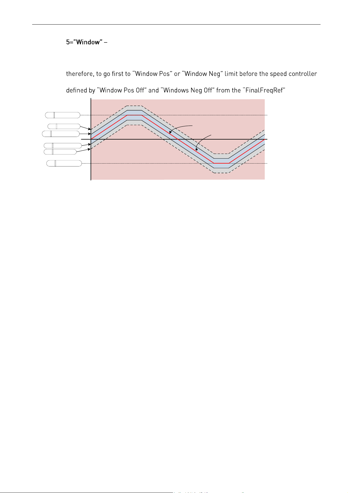
arfiff30 Generator VACON® • 77
Local contacts: http://drives.danfoss.com/danfoss-drives/local-contacts/
Classified as Business
Window control
Speed is limited within window from speed reference.
The speed control activation limit is different from the speed limit. The speed needs,
activates. When the speed controller is active, the speed will be restricted to the limit
.
P Window Pos Off
P Window Neg Off
P Pos Freq Limit
P Neg Freq Limit
P Window Neg
P Window Pos
Speed controller active
Speed
Reference
Torque Control
area
Speed controller active
Figure 8-7
Page 78

78 • VACON® arfiff30 Generator
Local contacts: http://drives.danfoss.com/danfoss-drives/local-contacts/
Classified as Business
2.2.1.6.2 Torque reference selection ID1929
P2.2.9.3 Torque Ref Max is used as a torque reference. When the drive is in stop state,
the reference is internally forced to zero.
P2.2.9.3 Torque Ref Max is scaled with G2.15 Curve parameters thus creating actual
speed dependent torque reference.
- Analogue Input 1.
P2.2.9.3 Torque Ref Max is scaled with Analogue Input 1 signal.
- Analogue Input 2.
P2.2.9.3 Torque Ref Max is scaled with Analogue Input 2 signal.
Analogue input 1, -10 Vdc... +10 Vdc. For joystick inputs, the maximum negative
Analogue input 2, -10 Vdc... +10 Vdc For joystick inputs, the maximum negative
Reference is taken from Fieldbus. V1.1.17 Torque Reference ID18.
P2.2.9.3 Torque Ref Max is scaled with G2.15 Curve parameters thus creating actual
speed dependent torque reference.
P2.2.9.3 Torque Ref Max is scaled with G2.15 Curve parameters thus creating actual
speed dependent torque reference.
2.2.1.6.3 Load Share ID1931 Load Share
Load Share for PTO operation. This parameter is used to adjust the load share between
different generators using this Generator application.
Page 79
arfiff30 Generator VACON® • 79
Local contacts: http://drives.danfoss.com/danfoss-drives/local-contacts/
Classified as Business
8.2.3 PTI-Boost
2.2.1.7.1 Torque Select ID1931
This parameter defines the speed limiting mode in torque control mode. This parameter
can be used as single motor control mode selection when no change is made between
open loop and closed loop controls.
See P2.2.1.6.1
- Speed control mode
The drive is forced to operate in speed control mode while the motor control mode
parameter is set to torque control mode thus allowing selection of speed control and
torque control mode with single parameter e.g. from Fieldbus.
- Positive and negative frequency limits
The speed is not limited by the speed reference, only by maximum frequency or Positive
and Negative frequency limit if set lower than maximum frequency parameter.
2= Ramp output for both directions
The speed is limited by reference after the ramp generator, thus speed will increase with
the set ramp time until the actual torque is equal to the reference torque. If the speed is
below the reference when the load is removed from the shaft, the speed will increase
without ramp.
This is the default selection. For the master-follower system we recommend you to use a
selection that allows a little higher reference for the torque follower so that the load will
be balanced equally, e.g. window control.
Minimum from speed reference and torque reference.
The minimum of the speed controller output and the torque reference is selected as final
torque reference.
Maximum from speed reference and torque reference
The maximum of the speed controller output and the torque reference is selected as
final torque reference.
Window control
The speed is limited within a window from the speed reference.
The speed control activation limit is different from the speed limit. The speed needs,
therefore, to go first to the
controller activates. When the speed controller is active, the speed will be restricted to
the .
Page 80
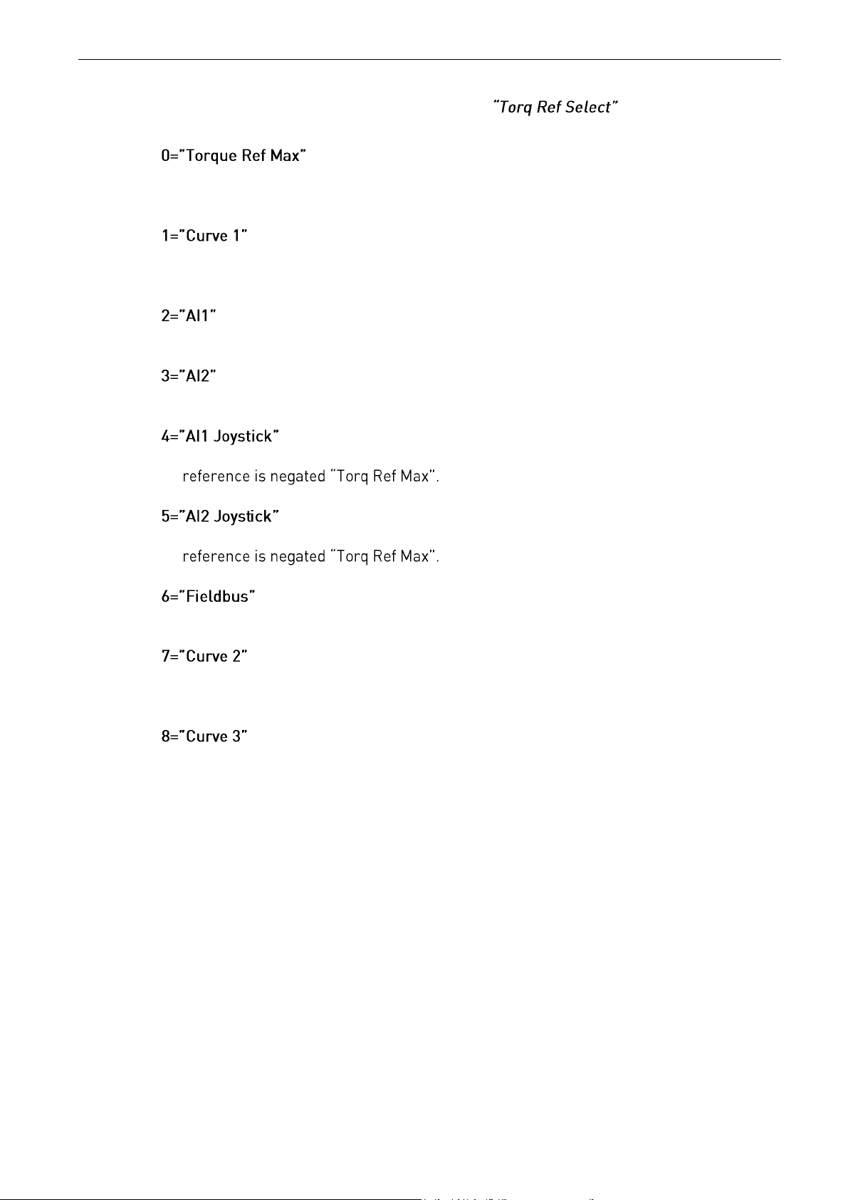
80 • VACON® arfiff30 Generator
Local contacts: http://drives.danfoss.com/danfoss-drives/local-contacts/
Classified as Business
2.2.1.7.2 Torque reference selection ID1929
P2.2.9.3 Torque Ref Max is used as torque reference. When the AC drive is in stop
state, the reference is internally forced to zero.
P2.2.9.3 Torque Ref Max is scaled with G2.15 Curve parameters thus creating actual
speed dependent torque reference.
- Analogue Input 1.
P2.2.9.3 Torque Ref Max is scaled with Analogue Input 1 signal.
- Analogue Input 2.
P2.2.9.3 Torque Ref Max is scaled with Analogue Input 2 signal.
Analogue input 1, -10 Vdc... +10 Vdc. For joystick inputs, the maximum negative
Analogue input 2, -10 Vdc... +10 Vdc For joystick inputs, the maximum negative
Reference is taken from Fieldbus. V1.1.17 Torque Reference ID18.
P2.2.9.3 Torque Ref Max is scaled with G2.15 Curve parameters thus creating actual
speed dependent torque reference.
P2.2.9.3 Torque Ref Max is scaled with G2.15 Curve parameters thus creating actual
speed dependent torque reference.
Page 81

arfiff30 Generator VACON® • 81
Local contacts: http://drives.danfoss.com/danfoss-drives/local-contacts/
Classified as Business
8.2.4 PTI 0-Speed
2.2.1.8.1 Torque Select ID1933
This parameter defines the speed limiting mode in torque control mode. This parameter
can be used as single motor control mode selection when no change is made between
open loop and closed loop controls.
See P2.2.1.6.1
- Speed control mode
The drive is forced to operate in speed control mode while the motor control mode
parameter is set to torque control mode thus allowing selection of speed control and
torque control mode with single parameter e.g. from Fieldbus.
- Positive and negative frequency limits
The speed is not limited by the speed reference, only by the maximum frequency or
Positive and Negative frequency limit if set lower than the maximum frequency
parameter.
Ramp output for both directions
The speed is limited by reference after the ramp generator, thus the speed will increase
with the set ramp time until the actual torque is equal to the reference torque. If the
speed is below the reference when the load is removed from the shaft, the speed will
increase without ramp.
This is the default selection. For the master-follower system we recommend you to use a
selection that allows a little higher reference for the torque follower so that the load will
be balanced equally, e.g. window control.
Minimum from speed reference and torque reference.
The minimum of the speed controller output and the torque reference is selected as final
torque reference.
Maximum from speed reference and torque reference
The maximum of the speed controller output and the torque reference is selected as
final torque reference.
Window control
The speed is limited within a window from the speed reference.
The speed control activation limit is different from the speed limit. The speed needs,
therefore, to go first to the
controller activates. When the speed controller is active, the speed will be restricted to
the .
Page 82

82 • VACON® arfiff30 Generator
Local contacts: http://drives.danfoss.com/danfoss-drives/local-contacts/
Classified as Business
2.2.1.8.2 Torque reference selection ID1932
P2.2.9.3 Torque Ref Max is used as torque reference. When the drive is in stop state,
the reference is internally forced to zero.
P2.2.9.3 Torque Ref Max is scaled with G2.15 Curve parameters thus creating actual
speed dependent torque reference.
- Analogue Input 1.
P2.2.9.3 Torque Ref Max is scaled with Analogue Input 1 signal.
- Analogue Input 2.
P2.2.9.3 Torque Ref Max is scaled with Analogue Input 2 signal.
Analogue input 1, -10 Vdc... +10 Vdc. For joystick inputs the maximum negative
Analogue input 2, -10 Vdc... +10 Vdc For joystick inputs the maximum negative
Reference is taken from Fieldbus. V1.1.17 Torque Reference ID18.
P2.2.9.3 Torque Ref Max is scaled with G2.15 Curve parameters thus creating actual
speed dependent torque reference.
P2.2.9.3 Torque Ref Max is scaled with G2.15 Curve parameters thus creating actual
speed dependent torque reference.
8.2.5 Regen Motor
2.2.1.9.1 License key ID1995
Enter here license code to activate Regen Motor operation for induction motor without
encoder.
Frequency range is from 30 Hz to 110 Hz. Starting in range of 40 Hz to 80 Hz with an
induction motor that has nominal voltage from 380 Vac to 690 Vac.
Drive will not use torque reference nor torque limits in this mode, limitation needs to be
done with Active Current limits and Power Limits.
Page 83

arfiff30 Generator VACON® • 83
Local contacts: http://drives.danfoss.com/danfoss-drives/local-contacts/
Classified as Business
8.2.6 Commissioning
2.2.1.10.1 MC Mode
Possibility to freely select the drive operation mode for commissioning purposes. By
default, the AC drive will not try to control the DC Link voltage in commissioning mode.
0 = AFE Operation
1 = Frequency control operation
2 = Open Loop Torque Control
3 = Closed Loop Speed Control
4 = Closed Loop Torque Contro.
2.2.1.10.2 DC Control
Possibility to activate the DC-Link Voltage Controller in commissioning operation.
2.2.1.10.3 Torque Select ID1278
This parameter defines the speed limiting mode in torque control mode. This parameter
can be used as single motor control mode selection when no change is made between
open loop and closed loop controls.
See P2.2.1.6.1
- Speed control mode
The drive is forced to operate in speed control mode while the motor control mode
parameter is set to torque control mode thus allowing selection of speed control and
torque control mode with single parameter e.g. from Fieldbus.
- Positive and negative frequency limits
The speed is not limited by the speed reference, but only by the maximum frequency or
Positive and Negative frequency limit if set lower than the maximum frequency
parameter.
Ramp output for both directions
The speed is limited by reference after the ramp generator, thus the speed will increase
with the set ramp time until the actual torque is equal to the reference torque. If the
speed is below the reference when the load is removed from the shaft, the speed will
increase without ramp.
This is the default selection. For master-follower system we recommend you to use a
selection that allows a little higher reference for the torque follower, so that the load will
be balanced equally, e.g. window control.
Minimum from speed reference and torque reference.
The minimum of the speed controller output and the torque reference is selected as final
torque reference.
Page 84

84 • VACON® arfiff30 Generator
Local contacts: http://drives.danfoss.com/danfoss-drives/local-contacts/
Classified as Business
Maximum from speed reference and torque reference
The maximum of the speed controller output and the torque reference is selected as
final torque reference.
Window control
The speed is limited within a window from the speed reference.
The speed control activation limit is different from the speed limit. The speed needs,
therefore, to go first to the eed
controller activates. When the speed controller is active, the speed will be restricted to
the
2.2.1.10.4 Torque reference selection ID641
P2.2.9.3 Torque Ref Max is used as torque reference. When the drive is in the stop
state, the reference is internally forced to zero.
P2.2.9.3 Torque Ref Max is scaled with G2.15 Curve parameters thus creating actual
speed dependent torque reference.
- Analogue Input 1.
P2.2.9.3 Torque Ref Max is scaled with Analogue Input 1 signal.
- Analogue Input 2.
P2.2.9.3 Torque Ref Max is scaled with Analogue Input 2 signal.
Analogue input 1, -10 Vdc... +10 Vdc. For joystick inputs the maximum negative
Analogue input 2, -10 Vdc... +10 Vdc For joystick inputs the maximum negative
Reference is taken from Fieldbus. V1.1.17 Torque Reference ID18.
P2.2.9.3 Torque Ref Max is scaled with G2.15 Curve parameters thus creating actual
speed dependent torque reference.
P2.2.9.3 Torque Ref Max is scaled with G2.15 Curve parameters thus creating actual
speed dependent torque reference.
Page 85

arfiff30 Generator VACON® • 85
Local contacts: http://drives.danfoss.com/danfoss-drives/local-contacts/
Classified as Business
8.2.7 DC Voltage Reference
2.2.2.1 System Nom. AC ID1201
Set this parameter if the DC voltage reference needs to be different than the nominal
voltage of the generator.
2.2.2.2 System Nom. DC ID1809
When the nominal DC is given, this value is used as a reference point for the DC Voltage
reference instead of the Grid Nominal Voltage. We recommend you to use this for any DC
voltage control operation. This parameter is also available in the Grid Converter
application and DC-DC Converter application.
2.2.2.3 DC Voltage Reference ID1462
This parameter sets the DC Voltage reference in % of Nominal DC voltage.
If P2.2.3.3 Nominal DC is zero then
Nominal DC voltage = 1.35 * Nominal Voltage (P2.1.2).
Final DC Voltage Ref (V1.1.2) = Nominal DC Voltage * DC Voltage Reference
The DC Voltage will be maintained at this level when running in generator mode.
There is internal limitation to reference: For 500V units the maximum limit is 797 Vdc
and for 690V units the maximum limit 1099 Vdc.
Maximum limit can be monitored from V1.1.15 DC Ref Max Lim.
NOTE! If the DC Voltage exceeds below values in stop state, the AC drive will lose ready
state:
1099 Vdc for 690V unit, immediate trip limit 1200 Vdc, U2t protection above 1100 Vdc.
By default, the internal DC Voltage reference is kept same as the actual DC voltage when
the AC drive is in stop state.
2.2.2.4 DC Droop ID620
When PTO modes are used in parallel, drooping can be used for current balancing. The
DC Voltage reference drooping is set as % of active current reference.
For example, if drooping is 3.00% and the active current is 50%, the DC voltage reference
is reduced to 1.5%. With drooping, the paralleled units can be balanced by adjusting the
DCVoltReference to slightly different values.
Page 86

86 • VACON® arfiff30 Generator
Local contacts: http://drives.danfoss.com/danfoss-drives/local-contacts/
Classified as Business
2.2.2.5 Reactive Current Reference ID1459
This parameter sets the reference for the reactive current in % of the nominal current.
This parameter can be used for power factor correction of the AFE system or reactive
power compensation. A positive value gives inductive compensation whereas a negative
value gives capacitive compensation.
2.2.2.6 DC voltage filter time ID1760
This parameter is used to filter the DC voltage reference from the actual value to a set
reference value when the control mode is changed to between different operation modes
where DC Voltage is controlled or not.
This will prevent overcurrent and current spikes when the control mode is changed.
8.2.8 Speed and Frequency
2.2.3.1 Speed Reference Select ID117
0 = Keypad Reference
Reference from keypad E3.2
1 = Analogue Input 1
2 = Analogue Input 2
3 = AI1 Joystick
4 = AI2 Joystick
5 = Fieldbus
Reference taken from V1.3.4 FB Torq Ref ID1140
2.2.3.2 Minimum Frequency ID101
Defines the minimum frequency of any adjustable reference input (i.e. reference is not a
parameter). The minimum frequency is bypassed when jogging speed, preset speed or
inching reference is used.
2.2.3.3 Maximum frequency ID102
Defines the maximum frequency limit for both negative and positive directions.
\ Frequency
Note: Do not change this parameter to a lower value than the current output frequency if
you change it during running. The change will be executed without ramp.
Page 87

arfiff30 Generator VACON® • 87
Local contacts: http://drives.danfoss.com/danfoss-drives/local-contacts/
Classified as Business
8.2.9 Torque Control
P2.2.4.1 PTI Torque reference scaling, minimum value ID643
The minimum torque reference for analogue input reference selections. Use negative
values to make the AC drive to operate on the generator side, and positive values for
motoring side operation.
P2.2.4.2 PTI Torque reference scaling, maximum value ID642
The maximum allowed torque reference for positive and negative values. Use negative
values to make the AC drive to operate on the generator side, and positive values for
motoring side operation.
This is also used for joystick input for negative maximum limit.
P2.2.4.3 PTO Torque reference scaling, minimum value ID1926
The minimum torque reference for analogue input reference selections. Use negative
values to make the AC drive to operate on the generator side, and positive values for
motoring side operation.
P2.2.4.4 PTO Torque reference scaling, maximum value ID1927
The maximum allowed torque reference for positive and negative values. Use negative
values to make the AC drive to operate on the generator side, and positive values for
motoring side operation.
This is also used for joystick input for negative maximum limit.
P2.2.4.5 Torque Reference Ramp Up Rate ID1934
Torque Reference absolute value increase rate.
P2.2.4.6 Torque Reference Ramp Down Rate ID1935
Torque reference absolute value decrease rate when going toward zero.
Page 88

88 • VACON® arfiff30 Generator
Local contacts: http://drives.danfoss.com/danfoss-drives/local-contacts/
Classified as Business
8.2.10 Ramp Control
P2.3.1 Start Function ID1274
0 = Ramp Start
1 = Flying Start
P2.3.2 Ramp Time ID103
Used ramp time for frequency reference while synchronization functions are not used.
P2.3.3 Acceleration/Deceleration ramp 1 shape ID500
The start and end of acceleration and deceleration ramps can be smoothed with these
parameters. Setting value to 0 gives a linear ramp shape which causes acceleration and
deceleration to act immediately to the changes in the reference signal. Setting other
value for this parameter produces an S-shaped acceleration/deceleration.
Page 89

arfiff30 Generator VACON® • 89
Local contacts: http://drives.danfoss.com/danfoss-drives/local-contacts/
Classified as Business
8.3 Input Signals
8.3.1 Basic Settings
P2.4.1.1 Start/Stop logic selection ID300
This parameter defines the start stop logic when using I/O control.
0 Start Drive No Action
1 - Start Pulse Stop Pulse
3-wire connection (pulse control):
DIN1: closed contact = start pulse
DIN2: open contact = stop pulse, falling edge.
Start 1
Start 2
Freq. Out
Figure 8-8. Start pulse/ Stop pulse.
The selections including the text 'Rising edge required to start' must be used to exclude
the possibility of an unintentional start when, for example, power is connected or reconnected after a power failure, after a fault reset, after the drive is stopped by Run
Enable (Run Enable = False) or when the control place is changed. The Start/Stop
contact must be opened before the motor can be started.
2 Rising pulse start Rising pulse stop
Page 90
90 • VACON® arfiff30 Generator
Local contacts: http://drives.danfoss.com/danfoss-drives/local-contacts/
Classified as Business
2.4.1.2 Input Inversion ID1091
Bit selection to invert input signal logic.
B00 = +1 = INV Open Contactor
B01 = +2 = INV Ext. Fault 1
B02 = +4 = INV Ext. Fault 2
B03 = +8 =
B04 = +16 = INV Klixon input 1
B05 = +32 = INV Klixon input 2
B06 = +64 = INV High Ambient temperature
B07 = +128 = INV Input Switch
8.3.2 Digital input signals
2.4.2.1 Start Signal 1 ID403
Signal selection 1 for the start/stop logic.
2.4.2.2 Start Signal 2 ID404
Signal selection 1 for the start/stop logic.
2.4.2.3 Open Contactor ID1600
This parameter is used to choose the input for Contactor Open signal. The signal is used
to force the main contactor open (MCC or MCC2) and stop modulating.
When this input is used to stop AFE and to open a main contactor, the DC-link must be
discharged and recharged to close the main contactor again and continue modulation
chosen.
2.4.2.4 MainContFeedBack ID1453
This parameter defines if the drive monitors the status of the main contactor (MCC 1) of
the unit. If the monitoring function is used, the unit monitors the status and will not start
if the state of the contactor does not correspond to the required status, i.e. is open when
it should be closed.
must be chosen.
2.4.2.5 Fault Reset ID414
Contact closed: All faults are reset.
Rising edge.
Page 91

arfiff30 Generator VACON® • 91
Local contacts: http://drives.danfoss.com/danfoss-drives/local-contacts/
Classified as Business
2.4.2.6 Ext Fault 1 ID405
Contact closed: Fault is displayed and motor stopped. Fault 51
2.4.2.7 Ext Fault 2 ID406
Contact open: Fault is displayed and motor stopped. Fault 51
2.4.2.8 Run Enable ID407
When signal is low drive will lose Ready status.
Contact open: Start of drive disabled.
Contact closed: Start of drive enabled.
2.4.2.9 Cooling Monitor ID750
OK input from the cooling unit.
2.4.2.10 Quick stop ID1213
Drive stops modulation immediately and opens main contactor
2.4.2.11 LCL Temperature ID1179
Digital input from LCL temperature monitoring
2.4.2.12 RR Enable
Enables the final run request command. Used for testing purposes when the precharge
control is started directly from start command and system must not go to run state.
Page 92
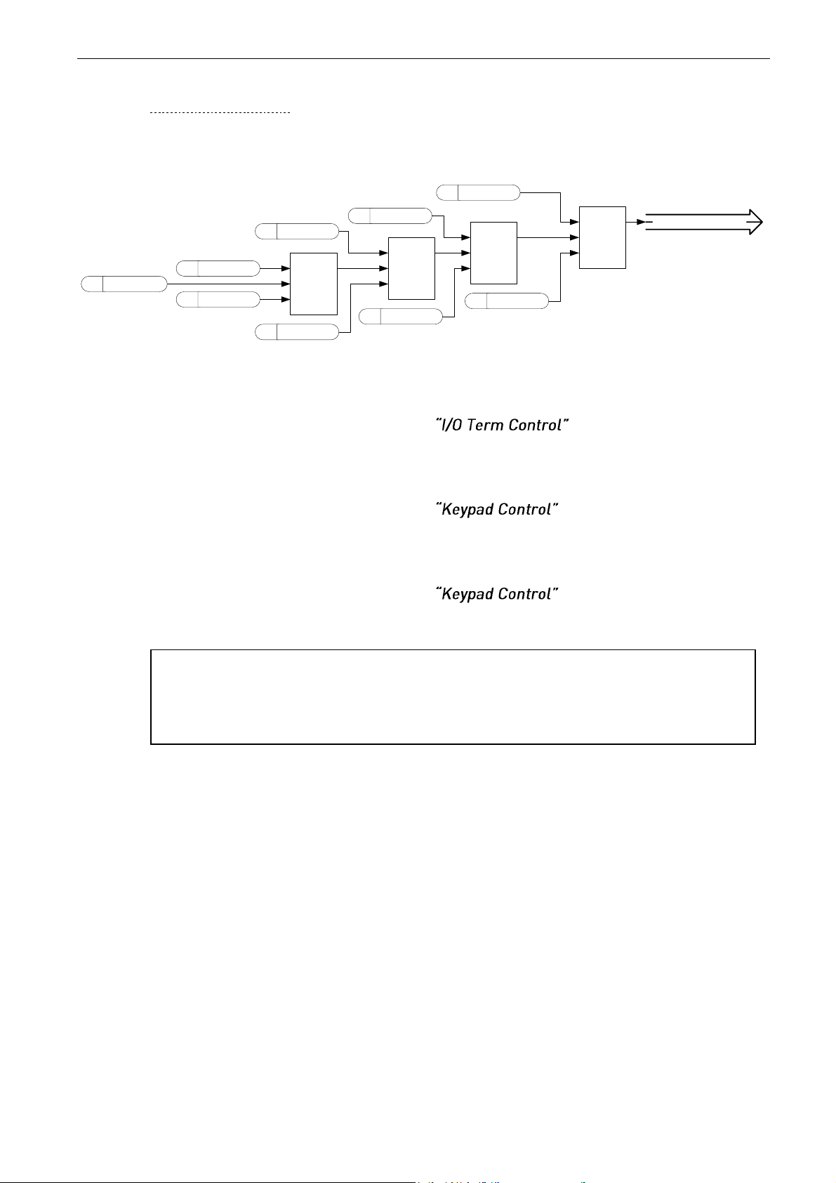
92 • VACON® arfiff30 Generator
Local contacts: http://drives.danfoss.com/danfoss-drives/local-contacts/
Classified as Business
8.3.2.1
Forced control place
Digital inputs can be used to bypass parameter P3.1 Control Place, for example, in an emergency
situation when the PLC is not able to send command to the drive.
SEL
G
IN 0
IN 1
SEL
G
IN 0
IN 1
DI IO Control
C IO Control
SEL
G
IN 0
IN 1
DI KP Control
C
KP Control
DI FB Control
SEL
G
IN 0
IN 1
C
FB Control
P
Control Place
Final Control Place
PC PC Control
C PC COntrol
Figure 8-9. Control place selection priority order
P2.4.2.13 Control from I/O terminal ID409
Contact closed: Force control place to I/O terminal
P2.4.2.14 Control from keypad ID410
Contact closed: Force control place to keypad
P2.4.2.15 Control from Fieldbus ID411
Contact closed: Force control place to fieldbus
P2.4.2.16 Power Take Mode 01
P2.4.2.17 Power Take Mode 10
Bit selection to change the Power Take mode. Set modes in G2.15
NOTE: When the control place is changed by force, the values of Start/Stop,
Direction and Reference valid in the respective control place are used. The value of
parameter ID125 (Keypad Control Place) does not change. When the input opens,
the control place is selected according to the keypad control parameter P3.1 Control
Page 93
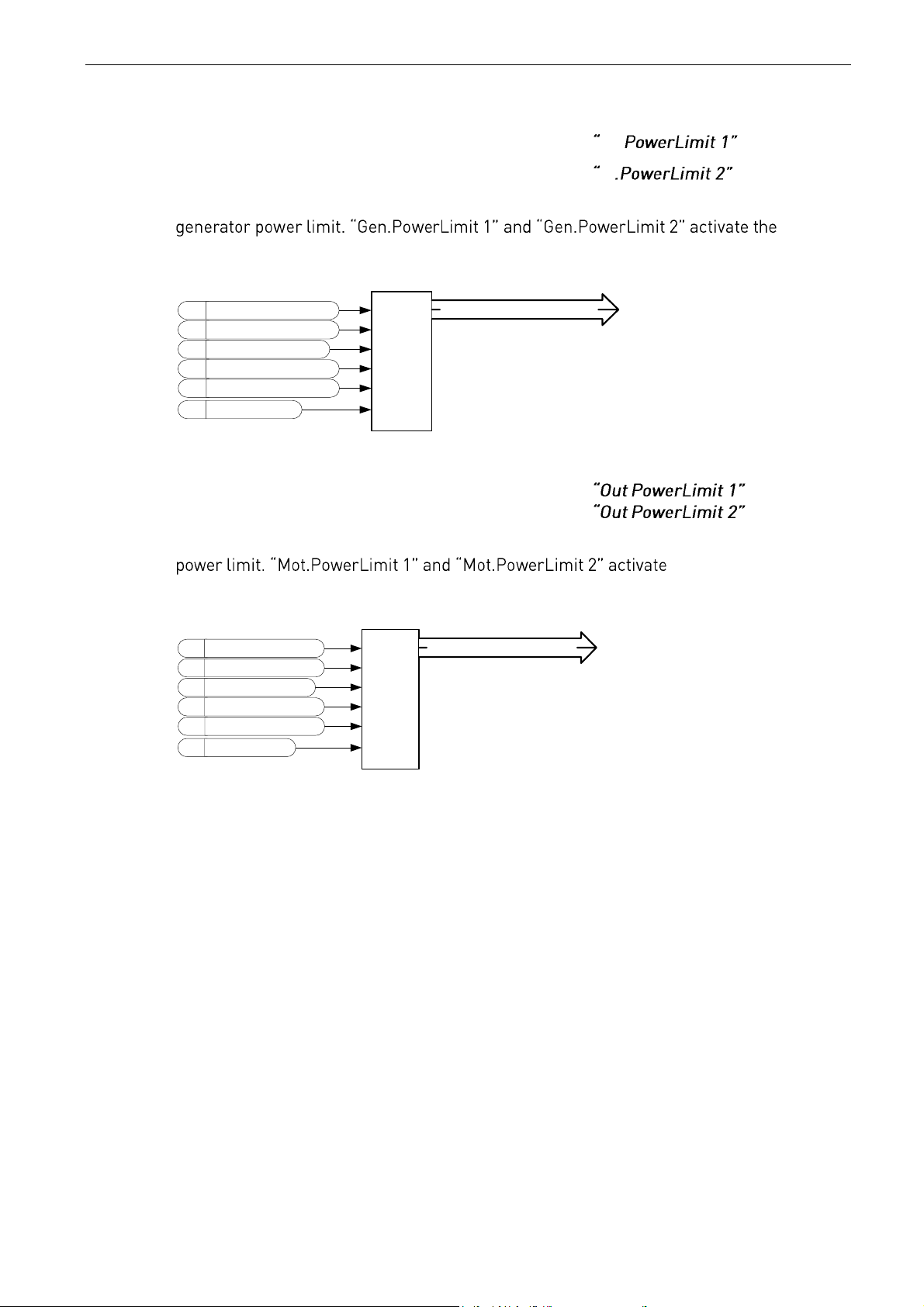
arfiff30 Generator VACON® • 93
Local contacts: http://drives.danfoss.com/danfoss-drives/local-contacts/
Classified as Business
P2.4.2.18 Input Power limit Digital input 1 ID1917 In.
P2.4.2.19 Input Power limit Digital input 2 ID1918 In
With these parameters you can select the desired digital input for controlling the
respective power limits defined in G2.6.2 Power Handling parameter group. If both inputs
are activated, the power limit is zero.
P Generator power limit 1
P Generator power limit 2
SEL4
B0
B1
IN00
IN01
IN10
IN11
F Power limit zero
P Generator power limit
DI Generator power limit 1
DI Generator power limit 2
Limit for ramping control
Figure 8-10
P2.4.2.20 Output Power limit Digital input 1 ID1919
P2.4.2.21 Output Power limit Digital input 2 ID1920
With this parameter you can select the desired digital input for controlling the motoring
the respective power
limits defined in parameter group G2.6.2 Power Handling. If both inputs are activated,
the power limit is zero.
P Motoring power limit 1
P Motoring power limit 2
SEL4
B0
B1
IN00
IN01
IN10
IN11
F Power limit zero
P Motoring power limit
DI Motoring power limit 1
DI Motoring power limit 2
Limit for ramping control
Figure 8-11
Page 94
94 • VACON® arfiff30 Generator
Local contacts: http://drives.danfoss.com/danfoss-drives/local-contacts/
Classified as Business
P2.4.2.25 Parameter Set 1/Set 2 selection ID496
With this parameter you can select between Parameter Set 1 and Set 2.
Remember to put the same input for both parameter sets. The parameter sets cannot be
changed when the AC drive is in run state.
Digital input = FALSE:
- Set 1 is loaded as the active set
Digital input = TRUE:
- Set 2 is loaded as the active set
When making two parameter sets from the keypad
1. Set all parameters as needed for SET1
2.
3. Set all parameters as needed for SET 1
4.
Note: The parameter values are stored only when selecting parameter P6.3.1 Parameter
sets Store Set 1 or Store Set 2 or from NCDrive: Drive > Parameter Sets.
P2.4.2.26 Klixon In 1 ID780
Klixon type temperature monitoring input 1. Low signal will generate warning W66 Klixon.
P2.4.2.27 Klixon In 2 ID781
Klixon type temperature monitoring input 2. Low signal will generate fault F66 Klixon.
P2.4.2.28 Input Switch ID1209
Selects the digital input for the status of input switch. The input switch is normally switch
fuse unit or main contactor with which the power is fed to the drive. If the input switch
P2.4.2.29 Ambient Temp ID783
Ambient temperature monitoring input Low signal will generate waring W88 Ambien
Temp.
Page 95
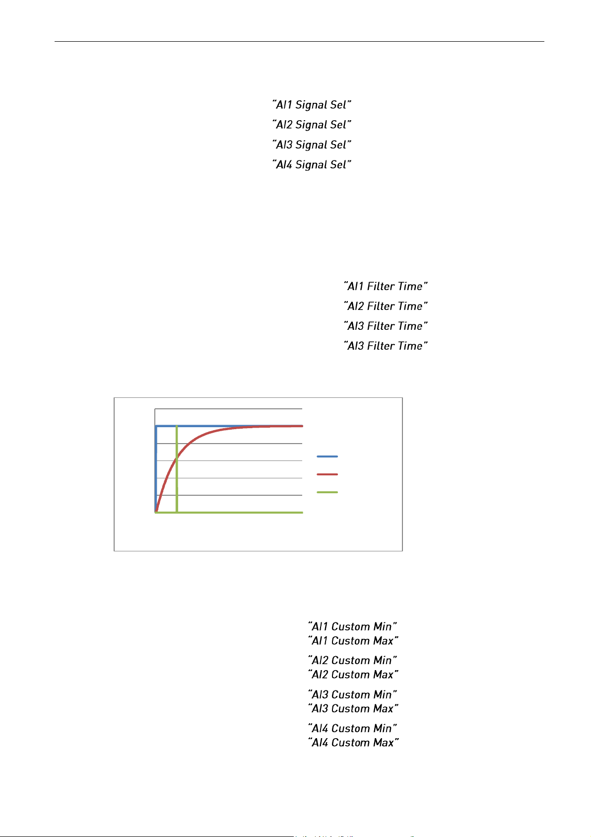
arfiff30 Generator VACON® • 95
Local contacts: http://drives.danfoss.com/danfoss-drives/local-contacts/
Classified as Business
8.3.3 Analogue Inputs 1-4
2.4.3.1 AI1 signal selection ID377
2.4.4.1 AI2 signal selection ID388
2.4.5.1 AI3 signal selection ID141
2.4.6.1 AI4 signal selection ID152
Connect the AI3/AI4 signal to the analogue input of your choice with this parameter.
When the analogue input selection parameter is set to 0.1, you can control the analogue
input monitoring variable from Fieldbus by assigning process data input ID number to
the monitoring signal. This allows the making of the scaling function in AC drive side to
the PLC input signals.
2.4.3.2 Analogue input 1 signal filtering time ID324
2.4.4.2 Analogue input 2 signal filtering time ID329
2.4.5.2 Analogue input 3 signal filtering time ID142
2.4.6.2 Analogue input 4 signal filtering time ID153
First order filtering is used for analogue inputs signals 3 and 4.
Figure 8-12
2.4.3.3 AI1 custom setting minimum ID321
2.4.3.4 AI1 custom setting maximum ID322
2.4.4.3 AI2 custom setting minimum ID326
2.4.4.4 AI2 custom setting maximum ID327
2.4.5.3 AI3 custom setting minimum ID144
2.4.5.4 AI3 custom setting maximum ID145
2.4.6.3 AI4 custom setting minimum ID155
2.4.6.4 AI4 custom setting maximum ID156
0
2000
4000
6000
8000
10000
12000
-0,045
0,545
1,135
1,725
2,315
2,905
3,495
4,085
4,675
5,265
5,855
6,445
Unfiltered
1 s filter time
63 %
Page 96

96 • VACON® arfiff30 Generator
Local contacts: http://drives.danfoss.com/danfoss-drives/local-contacts/
Classified as Business
Set the custom minimum and maximum input levels for the AI3 signal within -
AI3/AI4 Output
Analogue
Input
100 %
0 %
0 %
100 %
40 %
Custom
Min
80 %
Custom
Max
Figure 8-13
2.4.3.7 AI1 signal inversion ID387
2.4.4.7 AI2 signal inversion ID398
2.4.5.5 AI3 signal inversion ID151
2.4.6.5 AI4 signal inversion ID162
The signal inversion function is useful when, for example, the PLC is sending power limit
to the drive by using analogue inputs. If the PLC is unable to communicate to the drive,
the power limit would normally be zero, but by using the inverted signal logic the zero
value from the PLC would mean maximum power limit thus allowing to run the drive for
example from the keypad without changing the power limit function parameters.
0 = No inversion
1 = Signal inverted
AI3/AI4 Output
Analogue
Input
100 %
0 %
40 %
Custom
Min
80 %
Custom
Max
Figure 8-14
Page 97

arfiff30 Generator VACON® • 97
Local contacts: http://drives.danfoss.com/danfoss-drives/local-contacts/
Classified as Business
8.3.3.1
Analogue input to any parameter
This function allows control of any parameter by using analogue input. Use these parameters to
selecte the range of control area and the ID number for parameter that is controlled.
2.4.3.8 Analogue input 1, minimum value
2.4.3.9 Analogue input 1, maximum value
2.4.4.8 Analogue input 2, minimum value
2.4.4.9 Analogue input 2, maximum value
2.4.5.6 Analogue input 3, minimum value ID1037
2.4.5.7 Analogue input 3, maximum value ID1038
2.4.6.6 Analogue input 4, minimum value ID1039
2.4.6.7 Analogue input 4, maximum value ID1040
These parameters define the range for controlled parameter. All the values are
considered to be integers thus when controlling the FWP, you need to set also the digits
for decimals, for example, FWP 100.00 needs to be set as 10000.
2.4.3.10 AI1 Controlled ID ID1507
2.4.4.10 AI2 Controlled ID ID1511
2.4.5.8 AI3 Controlled ID ID1509
2.4.6.8 AI4 Controlled ID ID1510
These parameters define what the controller parameter is.
Example:
You want to control the motor field weakening point voltage by an analogue input from
70.00% to 130.00%.
Set Scale min to 7000 = 70.00%
Set Scale max to 13000 = 130.00%
Set Controlled ID to 603 Voltage at filed weakening point
AI3/AI4 Output = Field weakening point voltage
ID603
Analogue
Input
100 %
0 %
40 %
Custom
Min
80 %
Custom
Max
7000
Scale
Min
13000
Scale
Max
Figure 8-15
Now the analogue input 3 signal 0 V to 10 V (0 mA to 20 mA) will control the field
weakening point voltage between 70.00% - 130.00%. When setting the value, the
decimals are handled as integer.
Page 98

98 • VACON® arfiff30 Generator
Local contacts: http://drives.danfoss.com/danfoss-drives/local-contacts/
Classified as Business
8.4 Output Signals
8.4.1 Digital output signals
2.5.1.1 Main Contactor Contr Close
When P2.5.1.2 is not activated, this output will stay high as long as the MCC needs to be
closed. When the signal goes low, the MCC should be opened.
When P2.5.1.2 is activated, this will give only a closing command with two second pulse.
2.5.1.2 Main Contactor Contr Open
When this output is selected above 0.9. The AC drive will use the pulse control for the
MCC breaker.
P2.5.1.1 is used to close the breaker with a two second pulse.
Opening command is given by P2.5.1.2 with two second pulse.
2.5.1.3 Ready
The AC drive is ready to operate.
2.5.1.4 Run
The AC drive operates (the drive is modulating).
2.5.1.5 Fault
A fault trip has occurred.
2.5.1.6 Fault, Inverted
No fault trip has occurred.
2.5.1.7 At Ref. Speed
The voltage has reached the set reference.
2.5.1.8 OverTemp Warn.
The heatsink temperature exceeds +70°C.
2.5.1.9 Warning
General warning signal. Will go low when situation has passed.
If it must remain high, use the Common Alarm signals.
2.5.1.10 Charge control
When this is activated, the AC drive will start charging the DC from the start command
and go directly to run state. Charge is started from the start command.
2.5.1.11 Common alarm
The AC drive has a warning active. This indication needs to be reset separately even if the
situation has passed
2.5.1.12 Ready For Start
The AC drive has no interlock for starting the charging and going to run state.
2.5.1.13 Quick Stop Active
The AC Drive has received an quick stop command.
Page 99
arfiff30 Generator VACON® • 99
Local contacts: http://drives.danfoss.com/danfoss-drives/local-contacts/
Classified as Business
Fieldbus digital inputs connection
P2.5.1.14 Fieldbus input data 1 ID455
P2.5.1.16 Fieldbus input data 2 ID456
P2.5.1.18 Fieldbus input data 3 ID457
P2.5.1.20 Fieldbus input data 4 ID169
The data from the Fieldbus main control word can be led to the digital outputs of the AC
drive. See the applicable fieldbus board manual for location of these bits.
P2.5.1.15 Fieldbus digital input 1 parameter ID891
P2.5.1.17 Fieldbus digital input 2 parameter ID892
P2.5.1.19 Fieldbus digital input 3 parameter ID893
P2.5.1.21 Fieldbus digital input 4 parameter ID894
With these parameters you can define the parameter to be controlled by using FB Digital
input.
Example:
All option board inputs are in use and you still want to give DI: DC Brake Command
(ID416). You also have a fieldbus board in the drive.
Set parameter ID891 (Fieldbus digital input 1) to 416.
Now you are able to control the DC Braking command from the fieldbus by Profibus
control word (bit 11).
It is possible to control any parameter in the same way if values 0=FALSE and 1=TRUE
are significant for that parameter. For example, P2.6.5.3 Brake Chopper (ID504) can be
controlled on and off using this function (Brake Chopper; 0 = Not Used, 1 = On, Run).
2.5.1.22 Generator Operation Active
The AC drive is in generator operation.
2.5.1.24 Temperature limit supervision ID450 “Temp Lim Superv.”
The drive temperature goes beyond the set supervision limits defined in Supervision Lim
parameter group. The function can be set to monitor either the high or the low limit. Limit
and functions are selected in G2.5.8 Supervision Limits.
P2.5.1.25 Encoder 1 supervision function 1 ID3505
P2.5.1.25 Encoder 1 supervision function 2 ID3506
These functions monitors encode 1 frequency, limit and function is defined in parameter
group Supervision Lim. Its possible to set function monitor high or low frequency limit.
Page 100

100 • VACON® arfiff30 Generator
Local contacts: http://drives.danfoss.com/danfoss-drives/local-contacts/
Classified as Business
8.4.2 Delayed digital output 1 & 2
2.5.2.1 Dig.Out 1 Signal
2.4.3 .1 Dig.Out 2 Signal
Connect the delayed DO1 signal to the digital output of your choice with this parameter.
2.4.2.2 DO1 Content
2.4.3.2 DO2 Content
0=Not used
1=Ready
2=Run
3=Fault
4=Fault inverted
5=FC overheat warning
6=Ext. fault or warning
7=Ref. fault or warning
8=Warning
9=Reverse
10=SynchronizedToD7
11=Start Command given
12= FB DIN2
13=FB DIN3
14=ID.Bit DO, See P2.4.x.5
2.4.2.3 DO1 ON Delay
2.4.3.3 DO2 ON Delay
2.4.2.4 DO1 OFF Delay
2.4.3.4 DO2 OFF Delay
With these parameters you can set on- and off-delays to digital outputs.
Signal
DO
On
Delay
Off
Delay
 Loading...