

Page 1

vacon® nxp
ac drives
system drive
hardware manual
Page 2

Page 3

vacon • 3
TABLE OF CONTENTS
Document ID: DPD01365
Revision: C
Revision release date: 23.06.2020
1. Introduction ................................................................................................................ 5
1.1 Revision history ..................................................................................................................... 5
1.2 Scope of supply ..................................................................................................................... 5
1.3 Related brochures and manuals........................................................................................... 5
1.4 Definitions and abbreviations................................................................................................ 6
1.5 Project specifications............................................................................................................ 7
1.5.1 Parameters ............................................................................................................. 7
1.5.2 Sections and options ............................................................................................... 8
1.5.3 System layout and footprint drawings.................................................................... 8
1.6 Supplied documentation ....................................................................................................... 8
1.7 Storage .................................................................................................................................. 9
1.8 Lifting and moving the cabinet sections ............................................................................. 10
2. Safety........................................................................................................................ 11
2.1 Warnings ............................................................................................................................. 12
2.2 Cautions............................................................................................................................... 13
2.3 Grounding and ground fault protection .............................................................................. 14
3. Available sections ..................................................................................................... 15
3.1 Auxiliary device section....................................................................................................... 15
3.2 Main incoming section ........................................................................................................ 16
3.3 Non-regenerative front-end section................................................................................... 18
3.4 Active front-end section...................................................................................................... 20
3.5 Inverter unit section ............................................................................................................ 22
3.5.1 Drive sizes FR4-FR8 ............................................................................................. 22
3.5.2 Drive sizes FI9-FI14 .............................................................................................. 25
3.6 Dynamic brake section........................................................................................................ 28
3.7 Transport split unit.............................................................................................................. 29
4. Installation................................................................................................................ 30
4.1 Installation procedure......................................................................................................... 30
4.2 Preparing the installation site ............................................................................................ 31
4.2.1 Free space around the cabinet ............................................................................. 31
4.3 Mounting the cabinets......................................................................................................... 32
4.3.1 Fixing the cabinet to the floor and wall ................................................................ 32
4.3.2 Back-to-back installation ..................................................................................... 33
4.4 Connecting the busbars ...................................................................................................... 34
4.4.1 Side-by-side connection ....................................................................................... 34
4.4.2 Back-to-back connection...................................................................................... 35
4.5 Fixing the cabinet frames to each other ............................................................................. 36
4.6 Cabling................................................................................................................................. 37
4.6.1 Grounding.............................................................................................................. 37
4.6.2 Mains and motor connection ................................................................................ 37
4.6.3 EMC grounding ..................................................................................................... 42
4.6.4 Installation of ferrite rings (+OCM) on the motor cable ....................................... 42
4.6.5 Control connections .............................................................................................. 43
4.6.6 Auxiliary low-voltage connections........................................................................ 44
4.7 Screw tightening torques.................................................................................................... 45
5. Service ...................................................................................................................... 55
5.1 Warranty .............................................................................................................................. 55
5.2 Maintenance ........................................................................................................................ 55
5.3 Removing the drives from the cabinet................................................................................ 56
5.3.1 IUS_4 / IUS_6 ........................................................................................................ 56
5.3.2 IUS_7 / IUS_8 ........................................................................................................ 57
5.3.3 IUS_9 / IUS_10 ...................................................................................................... 58
5.3.4 IUS_12 ................................................................................................................... 61
5.3.5 IUS_13 / IUS_14 .................................................................................................... 64
6. Technical information ............................................................................................... 67
Local contacts: https://www.danfoss.com/en/contact-us/contacts-list/
Page 4

vacon • 4
6.1 Control and interface .......................................................................................................... 67
6.1.1 Control without speed feedback (open loop) ........................................................ 67
6.1.2 Control with speed feedback (closed loop) .......................................................... 67
6.2 Load definitions ................................................................................................................... 67
6.2.1 Pump and fan load ................................................................................................ 68
6.2.2 OL(
6.2.3 Starting torque >> OL(
6.2.4 OL(
6.2.5 OL(
n
n
n
base
base
base
) > OL(
) > OL(
) < OL(
n
) for constant torque load ..................................................... 69
max
n
) for constant torque load ......................................... 70
max
n
) for constant power load...................................................... 71
max
n
) for constant power load...................................................... 72
max
6.3 Technical specifications for VACON® drives ...................................................................... 73
6.3.1 NXN - Non-regenerative front end units.............................................................. 73
6.3.2 NXA - Active front-end units................................................................................. 75
6.3.3 NXI - Inverter units ............................................................................................... 77
6.3.4 NXB - Brake chopper units................................................................................... 82
Local contacts: https://www.danfoss.com/en/contact-us/contacts-list/
Page 5

Introduction vacon • 5
1. I
The VACON® NXP System Drive is a comprehensive configured common DC bus drive line up for
heavy-industry needs where round-the-clock activity is required leaving little time for maintenance.
All sections are grouped depending on their functionality, making it possible to plan each
installation phase according to your requirements. The engineered sections slot in alongside each
other allowing you to arrange integrated transport splits to save space. Alternatively, you can add
extra transport sections to speed up installation. All larger modules have slide-out mechanics for
easier set-up and maintenance.
The VACON® NXP System Drive is built to last. Items such as busbar systems and high/low power
devices are separated into individual compartments away from each other. This means that, if an
issue occurs, it is compartmentalized and doesn’t cause widespread failure helping to reduce
lifetime and maintenance costs.
NTRODUCTION
1.1 Revision history
This manual is regularly reviewed and updated. All suggestions for improvement are welcome.
The original language of this manual is English.
Table 1. Manual revision history
Rev.
Release
date
Changes/updates
A 17.12.2013 First version
B 07.01.2015
C 23.06.2020
Updated Chapter 2 “Available sections”.
Updated Chapter 4.3 “Removing the drives from the cabinet”.
Changes to the chapter structure of the manual.
Added Chapter 4.1 “Installation procedure”.
Updated Chapter 4.4 “Connecting the busbars”.
Added Chapter 4.6.3 “EMC grounding”.
Added Chapter 4.6.4 “Installation of ferrite rings (+OCM) on the motor cable”.
Added Chapter 4.6.6 “Auxiliary low-voltage connections”.
Added Chapter 4.7 “Screw tightening torques”.
1.2 Scope of supply
The scope of supply is limited to the drives listed in this manual. Process, machine or drive control
systems are not part of the scope of supply.
1.3 Related brochures and manuals
VACON® NX user manuals and brochures are available in PDF format on the Danfoss website at
www.danfoss.com.
• VACON® NXP Common DC Bus Selection Guide
• VACON® NXN NFE User manual
• VACON® NX Active Front End User Manual
• VACON® NX Inverters FI4-FI8 Operating Guide
• VACON® NX Inverters FI9-FI14 Operating Guide
Also manuals for different applications and option boards are available on the Danfoss website at
www.danfoss.com.
Local contacts: https://www.danfoss.com/en/contact-us/contacts-list/
Page 6

vacon • 6 Introduction
1.4 Definitions and abbreviations
ADS Auxiliary Device Section
AFS Active Front-end Section
DBS Dynamic Brake Section
DRL Drive List
IUS Inverter Unit Section
LV Low Voltage
MIS Main Incoming Section
NFS Non-regenerative Front-end Section
SLD Single Line Diagram
TSU Transport Split Unit
Local contacts: https://www.danfoss.com/en/contact-us/contacts-list/
Page 7

Introduction vacon • 7
1.5 Project specifications
1.5.1 Parameters
Project parameters are selected with the line-up configuration tool. Table 2 shows an example of
parameters selected with the configuration tool.
Table 2. Example of parameters selected from the configuration tool
Parameter Selection
Mains network type IT
Mains voltage 690 V AC
Frequency 50 Hz
Mains maximum current 2500 A
Busbar system DC+, DC-, PE
Busbar system voltage 1100 V DC
Busbar system maximum current 2500 A
Icw, 1 s
50 kA
PE design 50%
Busbars and flexibars Tinned
Cabinet type Rittal TS8
Height 2000 mm
Depth 600 mm
Cabinet material Powder coated steel
Sheet steel parts within the enclosure Without coating
Colour RAL 7035
Ingress protection of enclosure Protection against accidental touching of live parts
Protection barriers and covers IP 21
Ambient temperature 35°C
Halogen free wires and ducts No
Mimic diagram No
Type of packing Sea freight box
Application Industry
Local contacts: https://www.danfoss.com/en/contact-us/contacts-list/
Page 8

vacon • 8 Introduction
1.5.2 Sections and options
Sections and options are selected using the line-up configuration tool.
The available sections and options are introduced in Chapter 3.
Table 3. Example of selected sections and options from the configuration tool
# Section type Section category Options
1 ADS_600 Control +PES
2 MIS_2500 Incoming power +ICB
3 AFS_13 Incoming power 4 IUS_4 Outgoing power +ODU
5 IUS_10 Outgoing power +ODU
6 IUS_10 Outgoing power +ODU
7 IUS_12 Outgoing power +ISC, +ODU
8 IUS_7 Outgoing power +ODU
9 IUS_12 Outgoing power +ISC, +ODU
1.5.3 System layout and footprint drawings
System layout and footprint drawings are created based on the sections and options selected with
the line-up configuration tool.
1.6 Supplied documentation
Danfoss delivers technical documentation for the switchgear assembled AC drives according to the
Danfoss design standard. The documentation is provided in english.
The scope of supply regarding documentation does not include:
• Special requirements
• Delivery specific requirements
• Customer specific requirements (e.g. marking, naming, coding etc.)
Table 4. Supplied documentation
Document type Electronic format Paper copies
Cable connection table dwg, dxf or pdf 3 sets
Parts list dwg, dxf or pdf 3 sets
Wiring list dwg, dxf or pdf 3 sets
Circuit diagram dwg, dxf or pdf 3 sets
Switchgear layout drawing dwg, dxf or pdf 3 sets
Device layout drawing dwg, dxf or pdf 3 sets
VACON® manuals (as applicable)
Local contacts: https://www.danfoss.com/en/contact-us/contacts-list/
pdf 3 sets
Page 9

Introduction vacon • 9
1.7 Storage
If the system drive is to be kept in store before use, make sure that the ambient conditions are
acceptable:
• Storing temperature –40…+70 °C
• Relative humidity <95%, no condensation
The environment should also be free from dust. If there is dust in the air, the drive should be well
protected to make sure dust does not get into the drive.
If the drive is to be stored during longer periods, the power should be connected to the drive once
in 24 months and kept on for at least 2 hours. If the storage time exceeds 24 months the electrolytic
DC capacitors need to be charged with caution. Therefore, such a long storage time is not
recommended.
If the storing time is much longer than 24 months, the recharging of the capacitors has to be carried
out so that the possible high leakage current through the capacitors is limited. The best alternative
is to use a DC power supply with adjustable current limit. The current limit has to be set for example
to 300-500 mA and the DC power supply has to be connected to the B+/B- terminals (DC supply
terminals).
DC voltage must be adjusted to nominal DC voltage level of the unit (1.35xUn AC) and supplied at
least for 1 hour.
If DC voltage is not available and the unit has been stored de-energized much longer than 1 year,
consult factory before connecting power.
Local contacts: https://www.danfoss.com/en/contact-us/contacts-list/
Page 10
vacon • 10 Introduction
Min 60°
13858_00
13859_00
13006.emf
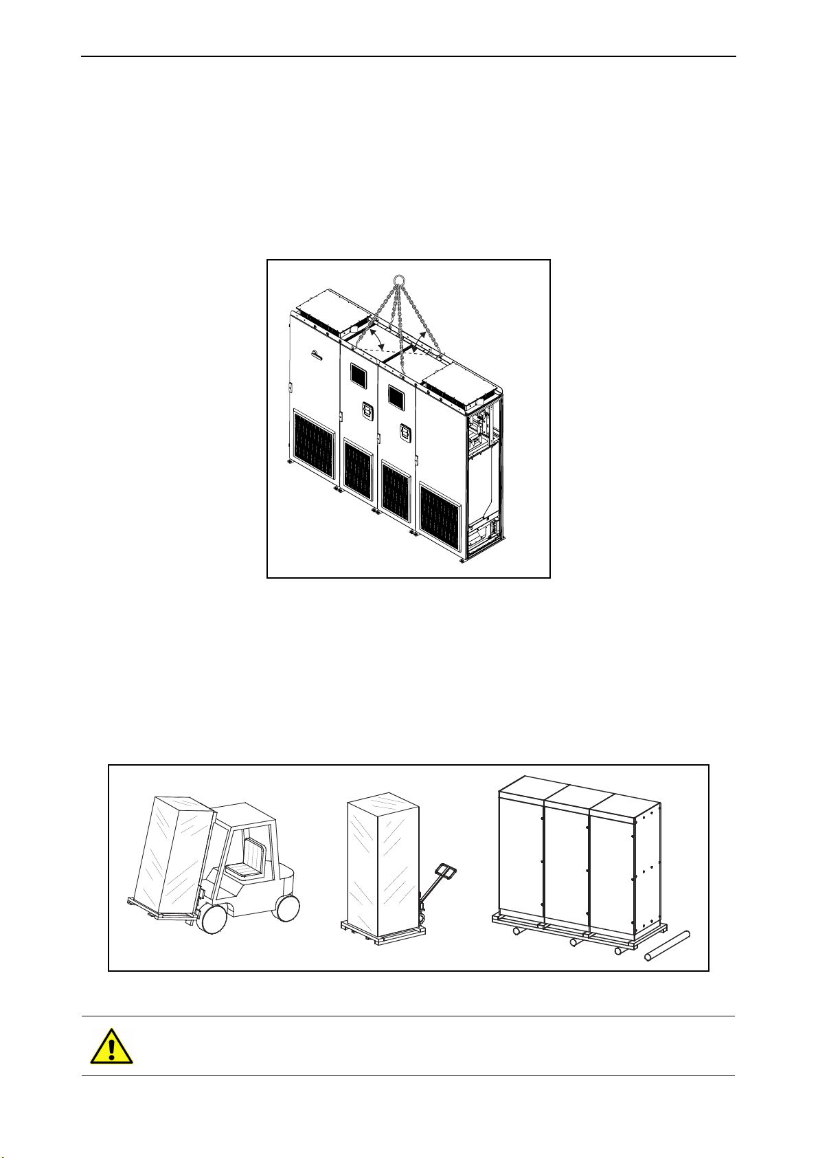
1.8 Lifting and moving the cabinet sections
For transport, the system drive is split into smaller sections. The cabinet sections are delivered
either in a wooden box or a wooden cage. The cabinets are transported vertically. Always refer to
shipping marks for more detailed information. To lift the cabinet sections, use lifting equipment
capable of handling the weight of the cabinets.
There are lifting beams on the top of the cabinets. Use the beams to lift and to move the cabinets to
the required location.
Figure 1. Lifting the cabinet sections
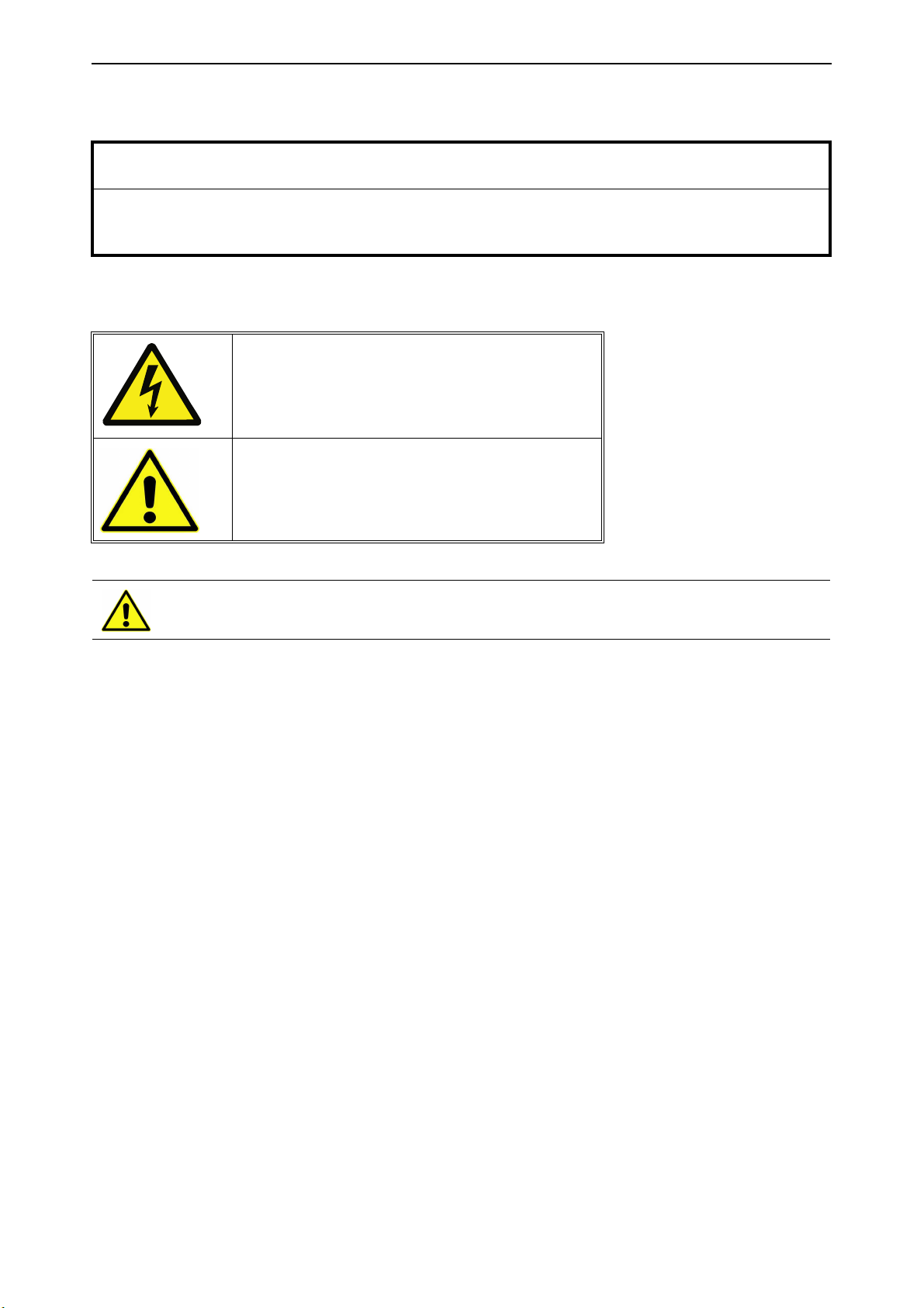
Moving of the cabinets on site can be carried out as follows by a forklift truck, a hoist or on rollers:
• Lower the package onto a level base
• Remove the package covering only at the site of installation
• Low, narrow or convoluted transport routes may require removal of the pallet prior to
movement
• Move packages in the upright position only
Figure 2. Moving the cabinet sections
Switchgear parts can easily topple backwards when manoeuvring on rollers or
manual trolleys because their centre of gravity is typically located high up at the rear
of the unit.
Local contacts: https://www.danfoss.com/en/contact-us/contacts-list/
Page 11
Safety vacon • 11
9000.emf
13006.emf
13006.emf
2. S
AFETY
NOTE! You can download the English and French product manuals with applicable safety,
warning and caution information from https://www.danfoss.com/en/service-and-support/.
REMARQUE Vous pouvez télécharger les versions anglaise et française des manuels produit
contenant l’ensemble des informations de sécurité, avertissements et mises en garde
applicables sur le site https://www.danfoss.com/en/service-and-support/.
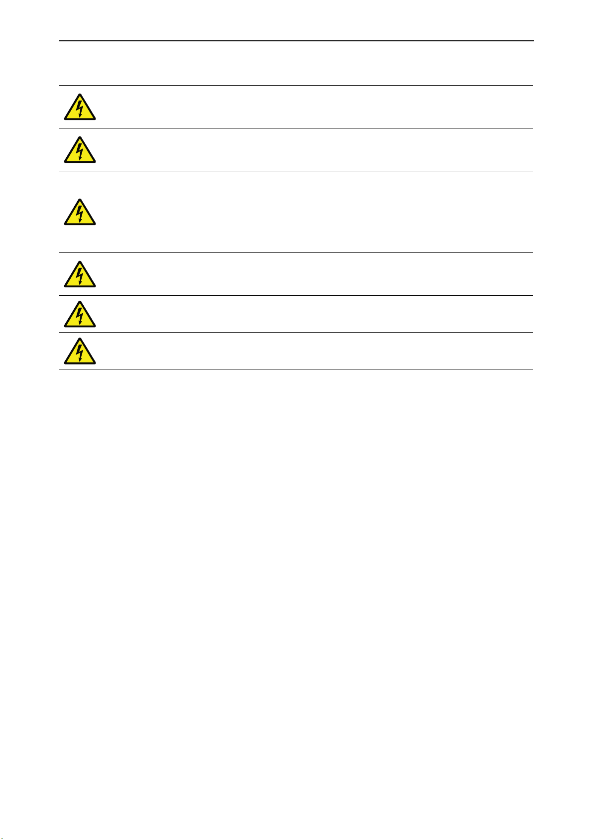
Please, read the information in cautions and warnings carefully.
The cautions and warnings are marked as follows:
= WARNING, dangerous voltage!
= CAUTION, possible damage to equipment!
Installation is only permitted to be carried out by a competent electrician!
Local contacts: https://www.danfoss.com/en/contact-us/contacts-list/
Page 12
vacon • 12 Safety
9000.emf
9000.emf
9000.emf
9000.emf
9000.emf
9000.emf
2.1 Warnings
The components of the power unit and all cabinet mounted devices are live when
the drive is connected to mains potential. Coming into contact with this voltage is
extremely dangerous and may cause death or severe injury.
The motor terminals U, V, W, the DC bus/brake resistor terminals and all other
mains devices are potentially live when the drive is connected to mains, even if the
motor is not running.
After disconnecting the AC drive from the mains, wait until the fan stops and the
indicators on the keypad go out (if no keypad is attached see the indicators on the
cover). Wait 5 more minutes before doing any work on the connections of the drive. Do
not open the cabinet door before this time has expired. After expiration of this time,
use measuring equipment to absolutely ensure that no voltage is present. Always
ensure the absence of voltage before starting any electrical work!
The control I/O-terminals are isolated from the mains potential. However, the relay
outputs and other I/O-terminals may have a dangerous control voltage present even
when the drive is disconnected from mains.
Before connecting the drive to mains make sure that the drive front and cable covers
as well as the cabinet doors are closed.
Wear protective gloves when you do mounting, cabling or maintenance operations.
There can be sharp edges in the AC drive that can cause cuts.
Local contacts: https://www.danfoss.com/en/contact-us/contacts-list/
Page 13

Safety vacon • 13
13006.emf
13006.emf
13006.emf
13006.emf
13006.emf
13006.emf
13006.emf
13006.emf
13006.emf
13006.emf
13006.emf
2.2 Cautions
VACON® AC drives are meant for
fixed installations only
.
Do not perform any measurements when the AC drive is connected to mains.
The touch current of VACON® AC drives exceeds 3.5 mAAC. According to standard
EN61800-5-1, a reinforced protective ground connection must be ensured. See
Chapter 2.3.
If the drive is used as a part of a machine, the machine manufacturer is responsible
for providing the machine with a supply disconnecting device (EN60204-1).
Only spare parts delivered by Danfoss can be used.
At power-up, power brake or fault reset the motor will start immediately if the start
signal is active, unless the pulse control for Start/Stop logic has been selected.
Futhermore, the I/O functionalities (including start inputs) may change if parameters,
applications or software are changed. Disconnect, therefore, the motor if an
unexpected start can cause danger.
The motor starts automatically after automatic fault reset if the autoreset function is
activated. See the Application Manual for more detailed information.
Prior to measurements on the motor or the motor cable, disconnect the motor cable
from the drive.
Do not touch the components on the circuit boards. Static voltage disharge may
damage the components.
Check that the EMC level of the AC drive corresponds to the requirements of the
supply network.
Make sure that the cooling is sufficient. If the AC drive becomes frequently too hot, the
lifetime of the drive will be shorter than usually.
Local contacts: https://www.danfoss.com/en/contact-us/contacts-list/
Page 14
vacon • 14 Safety
13006.emf
13006.emf
2.3 Grounding and ground fault protection
CAUTION!
The AC drive must always be grounded with a grounding conductor connected to the grounding terminal marked with:
The touch current of the AC drive exceeds 3.5 mA AC. According to EN61800-5-1, one or more of the
following conditions for the associated protective circuit shall be satisfied:
A fixed connection and
• the protective grounding conductor shall have a cross-sectional area of at least 10 mm2 Cu
or 16 mm2 Al, or
• an automatic disconnection of the supply in case of discontinuity of the protective grounding
conductor, or
• provision of an additional terminal for a second protective grounding conductor of the same
cross-sectional area as the original protective grounding conductor.
Table 5. Protective grounding conductor cross-section
Cross-sectional area of phase conductors (S)
[mm2]
S
≤16
16<S≤35
35<
S
Minimum cross-sectional area of the corre-
sponding protective grounding conductor
[mm2]
S
16
S
/2
The values above are valid only if the protective grounding conductor is made of the same metal
as the phase conductors. If this is not so, the cross-sectional area of the protective grounding
conductor shall be determined in a manner which produces a conductance equivalent to that
which results from the application of this table.
The cross-sectional area of every protective grounding conductor which does not form part of the
supply cable enclosure shall, in any case, be no less than:
• 2.5 mm2 if mechanical protection is provided or
• 4 mm2 if mechanical protection is not provided. For cord-connected equipment, provisions
shall be made so that the protective grounding conductor in the cord shall, in the case of
failure of the strain-relief mechanism, be the last conductor to be interrupted.
However, always follow the local regulations for the minimum size of the protective grounding
conductor.
NOTE! Due to the high capacitive currents present in the AC drive, fault current protective switches
may not function properly.
Do not perform any voltage withstand tests on any part of the AC drive. There is a
certain procedure according to which the test shall be performed. Ignoring this
procedure may result in a damaged product.
Local contacts: https://www.danfoss.com/en/contact-us/contacts-list/
Page 15
Available sections vacon • 15
3. A
VAILABLE SECTIONS
3.1 Auxiliary device section
The auxiliary device section (ADS) includes the common line-up controls. This section can be
customized for all application and segment needs. There are three ADS sizes available.
Table 6. ADS section size
ADS type Width x Height x Depth (mm)
ADS_400 400 x 2000 x 605
ADS_600 600 x 2000 x 605
ADS_800 800 x 2000 x 605
As standard the ADS section has the following equipment:
1. Control for the circuit breaker with +ICB selected
2. Indication of the mains status (fault, pre-charging and ON)
3. Auxiliary power supply 24 V, 5 A
4. Auxiliary Transformer, 2500 VA 1-phase supply (in bottom of cabinet)
5. Terminals for control and monitoring
As pre-engineered standard options, we can provide the following:
• Emergency stop CAT0 (+PES)
• Emergency stop CAT1 (+PED)
• Insulation fault sensor (+PIF)
• Arc protection relay (+PAP)
• Cabinet heater (+ACH)
• Cabinet light (+ACL)
• Auxiliary voltage transformer 4000 VA (+AT4)
• Auxiliary voltage 110 V AC (+AT1)
• Auxiliary power supply 24 V, 10 A (+ADC)
• Cabling from the top (+CIT)
• Empty auxiliary 600 mm cabinet with door (+G60)
• UL approved design and components (+NAR)
• Customer specific option (+CSO)
+PAP will have sub units in selected sections if needed, please refer to the circuit diagrams.
Local contacts: https://www.danfoss.com/en/contact-us/contacts-list/
Page 16

vacon • 16 Available sections
3.2 Main incoming section
The main incoming section (MIS) includes the main incoming device. The main incoming device and
size is dependent on the required current of the complete line-up.
Table 7. Available MIS sizes
MIS type Input current Width x Height x Depth (mm)
MIS_630 630 A 400 x 2000 x 605
MIS_800 800 A 600 x 2000 x 605
MIS_1000 1000 A 600 x 2000 x 605
MIS_1250 1250 A 600 x 2000 x 605
MIS_1600 1600 A 600 x 2000 x 605
MIS_2000 2000 A 600 x 2000 x 605
MIS_2500 2500 A 600 x 2000 x 605
MIS_3200 3200 A 800 x 2000 x 605
MIS_4000 4000 A 800 x 2000 x 605
MIS_5000 5000 A 800 x 2000 x 605
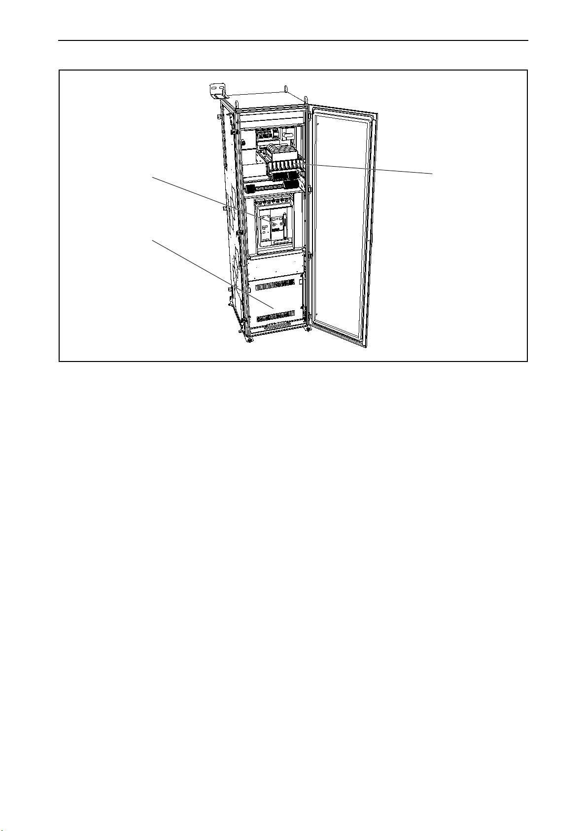
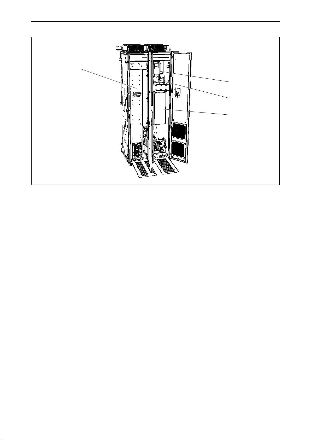
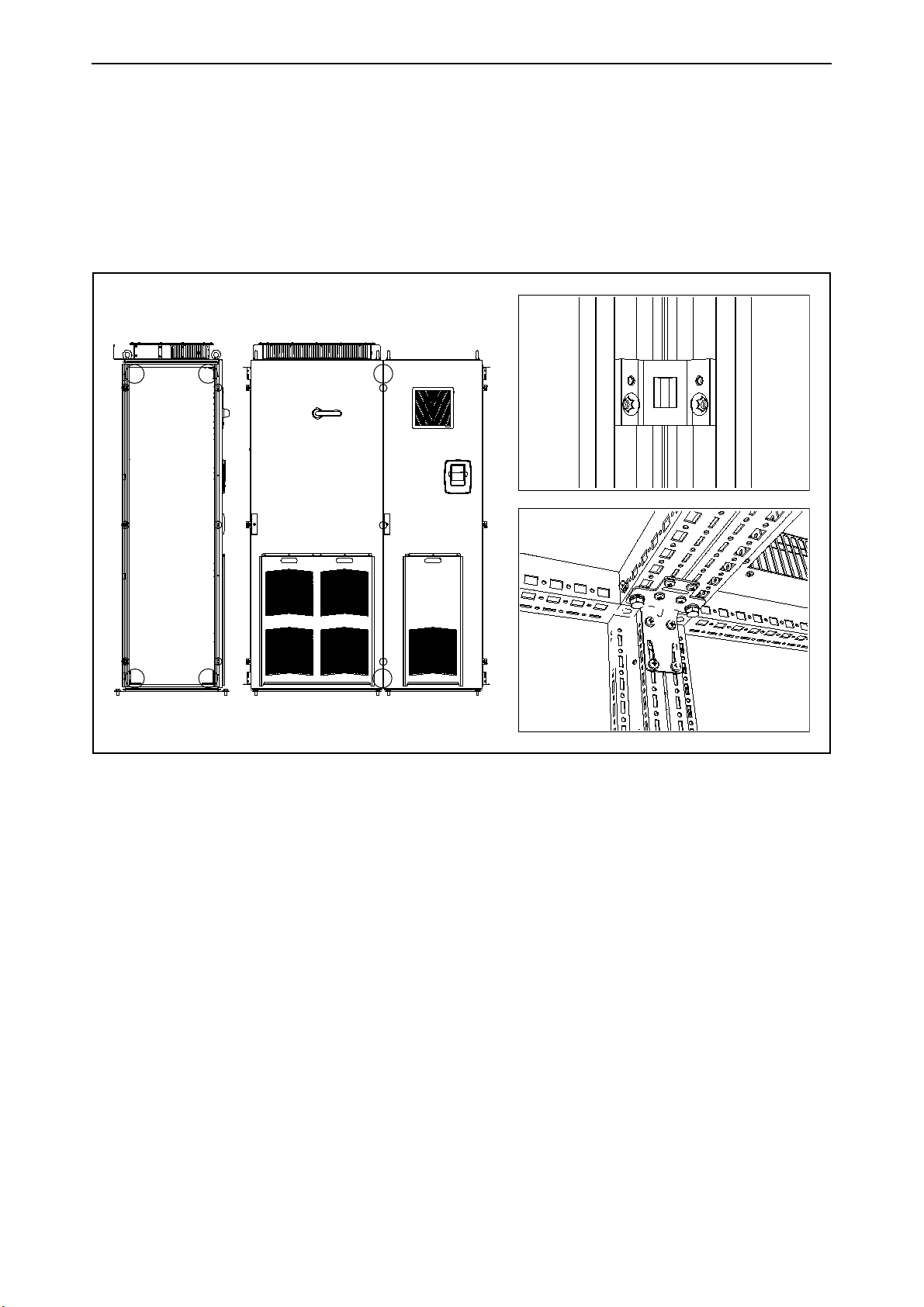
As standard the MIS section has the following equipment (see Figure 3):
1. Air circuit breaker
2. Mains connections
3. Digital multi instrument with field bus connection
4. Pre-charging components for AFE
As pre-engineered standard options we can provide the following:
• Cabling from the top (+CIT)
• Ground Switch (+ILE)
• Current transducers (+ITR)
• UL approved design and components (+NAR)
• Arc detection (+ADU)
• Cabinet heater (+ACH)
• Cabinet light (+ACL)
+ILE requires an additional section.
Local contacts: https://www.danfoss.com/en/contact-us/contacts-list/
Page 17
Available sections vacon • 17
1
2
4
13849_00
Figure 3. Example of main incoming section MIS_1600
Local contacts: https://www.danfoss.com/en/contact-us/contacts-list/
Page 18

vacon • 18 Available sections
3.3 Non-regenerative front-end section
The non-regenerative front-end section (NFS) includes one or multiple NXN units from the VACON®
NXP product series. The NXN is a non-regenerative supply unit that can be utilized in 6-pulse, 12pulse, 18-pulse and 24-pulse systems.
Table 8. Available NFS sections
NFS type Number of NXN units Width x Height x Depth (mm)
NFS_1x* 1 800 x 2100 x 605
NFS_2x* 2 800 x 2100 x 605
* _M selection for mirrored design.
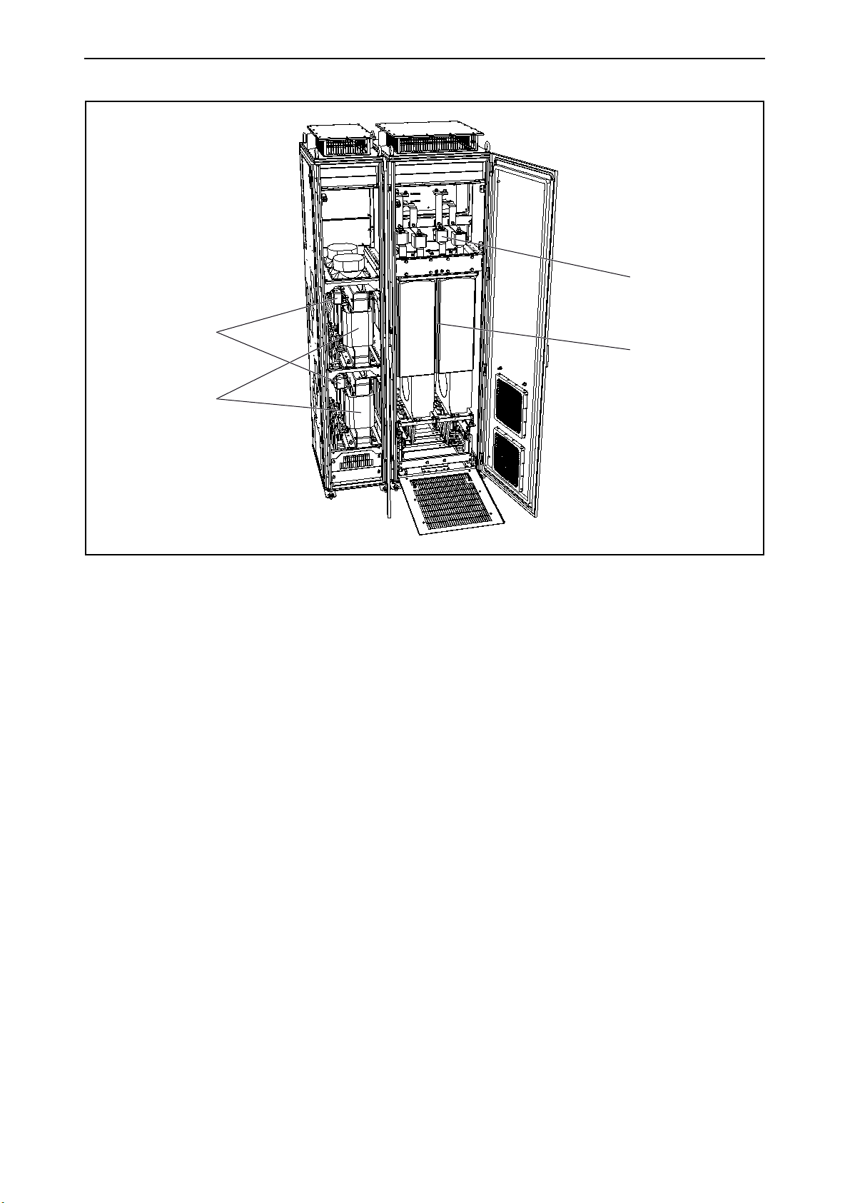
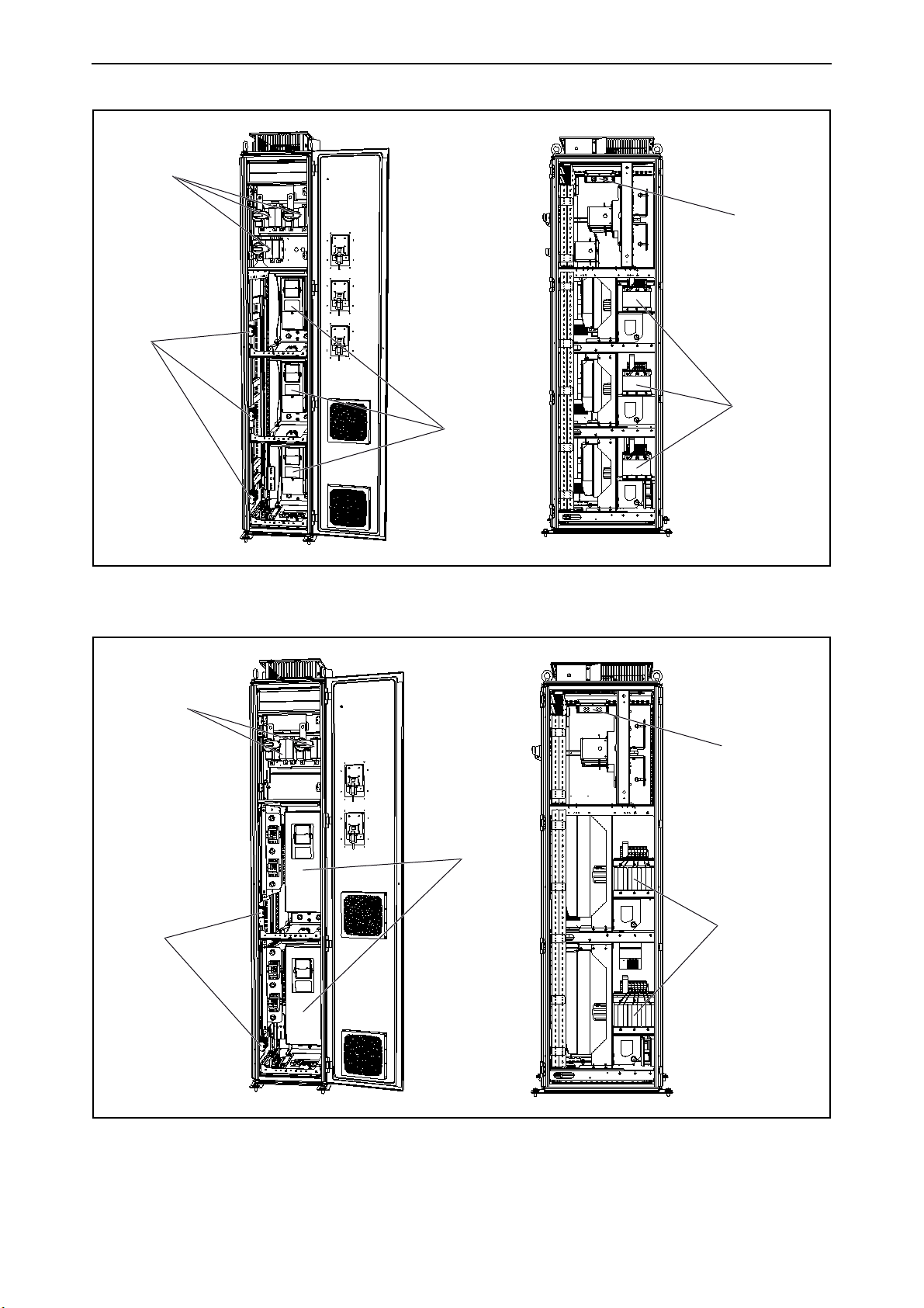
As standard the NFS section includes the following (see Figure 4):
1. The NXN unit(s)
2. Chokes
3. Terminals for control and indication signals (installed in MIS or ADS section)
4. DC fuses for the Supply Unit
5. AC fuses for the filter
As pre-engineered standard options we can provide the following:
• UL approved design and components (+NAR)
• Arc detection (+ADU)
• Cabinet heater (+ACH)
• Cabinet light (+ACL)
Local contacts: https://www.danfoss.com/en/contact-us/contacts-list/
Page 19
Available sections vacon • 19
2
4
5
1
13850_00
Figure 4. Example of non-regenerative front-end section NFS_2x
Local contacts: https://www.danfoss.com/en/contact-us/contacts-list/
Page 20
vacon • 20 Available sections
3.4 Active front-end section
The active front-end section (AFS) includes an LCL-filter and an NXA unit from the VACON® NXP
product series. The active front-end provides low THD(I) and several units can be connected in
parallel providing full or reduced redundancy.
Table 9. Available AFS sections
AFS type Drive size Width x Height x Depth (mm)
AFS_9*/**
AFS_10*/**
AFS_13*/**
AFS_13_2x*/**
* _M selection for mirrored design.
** +AC, AC busbars for two or more AFS sections after the MIS section, limited to 2600 A per side of
the MIS.
*** Dimensions including LCL.
FI9 800 x 2100 x 605***
FI10 800 x 2100 x 605***
FI13 1400 x 2100 x 605***
FI13 3200 x 2100 x 605***
As standard the AFS sections include the following (see Figure 5):
1. LCL Filter
2. The NXA unit
3. Control unit
4. Pre-charging components (installed in MIS section)
5. Terminals for control and indication signals (installed in MIS or ADS section)
6. DC fuses for the Supply Unit
7. AC fuses for the filter (installed in MIS section)
As pre-engineered standard options we can provide the following:
• UL approved design and components (+NAR)
• Arc detection (+ADU)
• Cabinet heater (+ACH)
• Cabinet light (+ACL)
Local contacts: https://www.danfoss.com/en/contact-us/contacts-list/
Page 21
Available sections vacon • 21
1
2
3
6
13851_00
Figure 5. Example of active front-end section AFS_9
Local contacts: https://www.danfoss.com/en/contact-us/contacts-list/
Page 22

vacon • 22 Available sections
3.5 Inverter unit section
3.5.1 Drive sizes FR4-FR8
The inverter unit section (IUS) includes one or several smaller NXI drives from the VACON® NXP
product series. The inverter units are all VACON® NXP premium drives.
Table 10. Available IUS section sizes FR4-FR8
IUS type Drive size Number of drives/ section Width x Height x Depth (mm)
IUS_4_x FR4*
1-3 400 x 2100 x 605**
4-14 1200 x 2100 x 605**
IUS_6_x FR6 1-2 400 x 2100 x 605**
IUS_7 FR7 1 400 x 2100 x 605**
IUS_8 FR8 1 400 x 2100 x 605**
COT_4-8*** - - 400 x 2000 x 605
* Only option board and fieldbus options
**Top exit +400 mm can be shared between two sections
*** Section for cabling with top cabling option (+COT)
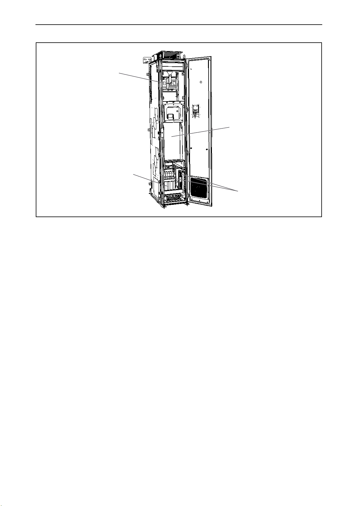
As standard the IUS section includes the following (see Figure 6):
1. Input fuses (DC fuses)
2. Fuse switch (IEC FR4-FR6)
3. The NXI drive(s)
4. Control box (integrated into the module)
5. Terminals for control and indication signals
As pre-engineered standard options we can provide the following:
• dU/dt (+ODU)
• Input Switch, DC disconnect (+ISD)
• Arc detection (+ADU)
• Motor fan control (+AMF)
• Motor heater feeder (+AMH)
• Mechanical break control (+AMB)
• Top cabling (+COT)
• UL approved design and components (+NAR)
• Cabinet heater (+ACH)
• Cabinet light (+ACL)
Local contacts: https://www.danfoss.com/en/contact-us/contacts-list/
Page 23
Available sections vacon • 23
1+2
5
3+4
+ODU
+ACL
13852_00
1+2
5
3+4
+ODU
13853_00
+ACL
Figure 6. Example of inverter unit IUS_4
Figure 7. Example of inverter unit IUS_6
Local contacts: https://www.danfoss.com/en/contact-us/contacts-list/
Page 24
vacon • 24 Available sections
1
+ODU
3+4
5
13854_00
Figure 8. Example of inverter unit IUS_8
Local contacts: https://www.danfoss.com/en/contact-us/contacts-list/
Page 25

Available sections vacon • 25
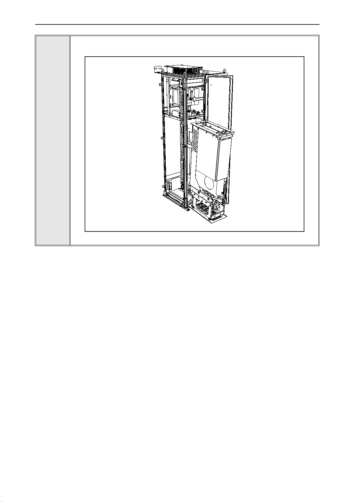
3.5.2 Drive sizes FI9-FI14
The inverter unit section (IUS) includes the largest NXI drives from the VACON® product series. The
inverter units are all VACON® NXP premium drives.
Table 11. Available IUS section sizes FI9-FI14
IUS type Drive size Width x Height x Depth (mm)
Width x Height x Depth (mm),
with +ODU
IUS_9 FI9 800 x 2100 x 605 800 x 2100 x 605
IUS_9_2x FI9 1200 x 2100 x 605 1200 x 2100 x 605
IUS_10 FI10 800 x 2100 x 605 800 x 2100 x 605
IUS_10_2x FI10 1200 x 2100 x 605 1200 x 2100 x 605
IUS_12 FI12 1000 x 2100 x 605 1000 x 2100 x 605
IUS_12_2x FI12 1800 x 2100 x 605 Not available
IUS_13 FI13 1400 x 2100 x 605 1400 x 2100 x 605
IUS_14 FI14 2800 x 2100 x 605 2800 x 2100 x 605
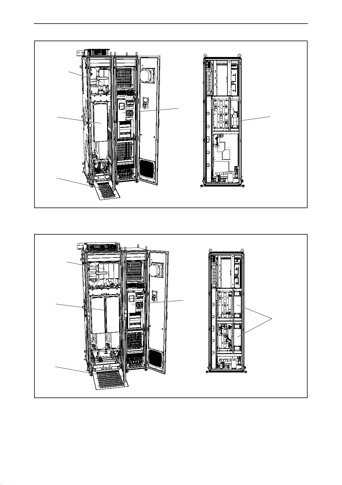
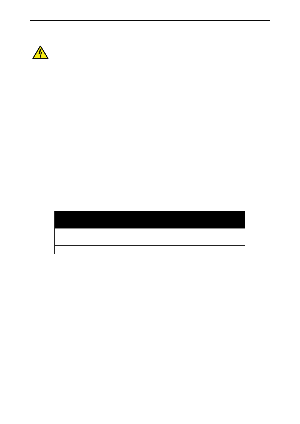
As standard the IUS section includes the following (see Figure 9):
1. Input fuses (DC fuses)
2. The NXI drive
3. Service platform/module removal
4. Control section and fixed external terminals, 70 pcs
As pre-engineered standard options we can provide the following:
• dU/dt (+ODU)
• Common mode filter (+OCM)
• Input Switch with charging (+ISC)
• Arc detection (+ADU)
• Motor fan control (+AMF)
• Motor heater feeder (+AMH)
• Mechanical break control (+AMB)
• Top cabling (+COT)
• UL approved design and components (+NAR)
• Cabinet heater (+ACH)
• Cabinet light (+ACL)
Local contacts: https://www.danfoss.com/en/contact-us/contacts-list/
Page 26
vacon • 26 Available sections
+ISC
2
3
+ODU
4
13855_00
+ISC
2
3
4
+ODU
13856_00
Figure 9. Example of inverter unit IUS_9
Figure 10. Example of inverter unit IUS_12
Local contacts: https://www.danfoss.com/en/contact-us/contacts-list/
Page 27

Available sections vacon • 27
+ISC
2
3
4
+ODU
13857_00
Figure 11. Example of inverter unit IUS_13
Local contacts: https://www.danfoss.com/en/contact-us/contacts-list/
Page 28

vacon • 28 Available sections
3.6 Dynamic brake section
The dynamic brake section (DBS) includes the largest NXI drives from the VACON® NXP product
series. The brake units are all VACON® NXP premium drives.
As standard the DBS section includes the following:
1. Input fuses (DC fuses)
2. The NXI brake chopper
3. Service platform/module removal
4. Control section and fixed external terminals, 70 pcs
As pre-engineered standard options we can provide the following:
• Input Switch (with charging) (+ISC)
• Input Switch (DC-disconnect) (+ISD)
• Arc detection (+ADU)
• Top cabling (+COT)
• UL approved design and components (+NAR)
• Cabinet heater (+ACH)
• Cabinet light (+ACL)
The dynamic brake sections are similar to the inverter unit sections. See the dimensions and
example figures in Chapter 3.5.2.
Local contacts: https://www.danfoss.com/en/contact-us/contacts-list/
Page 29

Available sections vacon • 29
3.7 Transport split unit
Transport Split Units are available for easy access to main bus joints between sections.
Table 12. Available TSU section sizes
TSU type Width x Height x Depth (mm)
TSU_200 200 x 2000 x 605
TSU_300 300 x 2000 x 605
Local contacts: https://www.danfoss.com/en/contact-us/contacts-list/
Page 30
vacon • 30 Installation
4. I
4.1 Installation procedure
Each VACON® NXP System Drive delivery is project specific. The following installation sequence is
a general description of the process of connecting the cabinet sections and installing the system
drive.
As each installation is project specific, the instructions and illustrations in the following chapters
are general examples. More detailed instructions, such as layout drawings, dimensions and wiring
diagrams, are included in the project delivery.
1
2
3
4
NSTALLATION
Before starting the installation, read the safety instructions in Chapter 2 carefully.
Make sure that the ambient conditions at the installation site are according to the
specifications. See the specifications in Chapter 6.3.
Remove the package covering from the product only at the installation site and in the
specified ambient conditions.
Before moving the cabinets to the installation site, make sure that the space is
properly prepared for the installation. See Chapter 4.2.
Move the cabinets to the installation site. See the instructions in Chapter 1.8.
5
6
7
8
9
10
11
12
13
14
15
16
17
Make sure that there is enough free space around the cabinets. See Chapter 4.2.1.
Lift the first cabinet section into the desired installation location. See Chapter 4.3.
Fix the first cabinet section to the floor or wall. See Chapter 4.3.
Lift the second cabinet section next to the first section, in a position from which it can
be pushed into place.
Before pushing the cabinets together, loosen the nuts and bolts on the ends of the
busbars to be connected. See Chapter 4.4.
Push the cabinets together, make sure that the busbars come together properly.
Connect the busbars by tightening the nuts and bolts on the busbars. See Chapter 4.4.
Mount the cabinet frames to each other. See Chapter 4.5.
Mount the second section to the floor or wall.
Install the rest of the sections following the same procedure.
Once all the cabinets are connected, remove the lifting beams from the top of the
cabinets, so that they do not block the air flow. After the beams are removed, mount
the bolts back on the cabinet roof.
Do the cabling between cabinets (auxiliary low-voltage connections, fiber
connections, etc.). See the project specific wiring diagrams, which are included in the
delivery.
Connect the motor and mains cables to the system drive. Pay attention to grounding
of the cables. See Chapter 4.6.
Local contacts: https://www.danfoss.com/en/contact-us/contacts-list/
Page 31

Installation vacon • 31
200 mm
1000 mm
13860_00
4.2 Preparing the installation site
Before starting the installation work make sure that the level of the floor is within acceptable limits.
The maximum deviation from the basic level can be no more than 5 mm over a 3 m distance. The
maximum acceptable height difference between cabinet front and rear edges should be within
+2/-0 mm limit.
4.2.1 Free space around the cabinet
Enough space must be left above and in front of the cabinet to ensure sufficient cooling and space
for maintenance.
It is recommended to leave at least 200 mm above and 1000 mm in front of the cabinets.
Also make sure that the temperature of the cooling air does not exceed the maximum ambient
temperature of the drives.
Figure 12. Required space around the cabinet
Local contacts: https://www.danfoss.com/en/contact-us/contacts-list/
Page 32

vacon • 32 Installation
2 2 2
11
1
2
3
13861_00
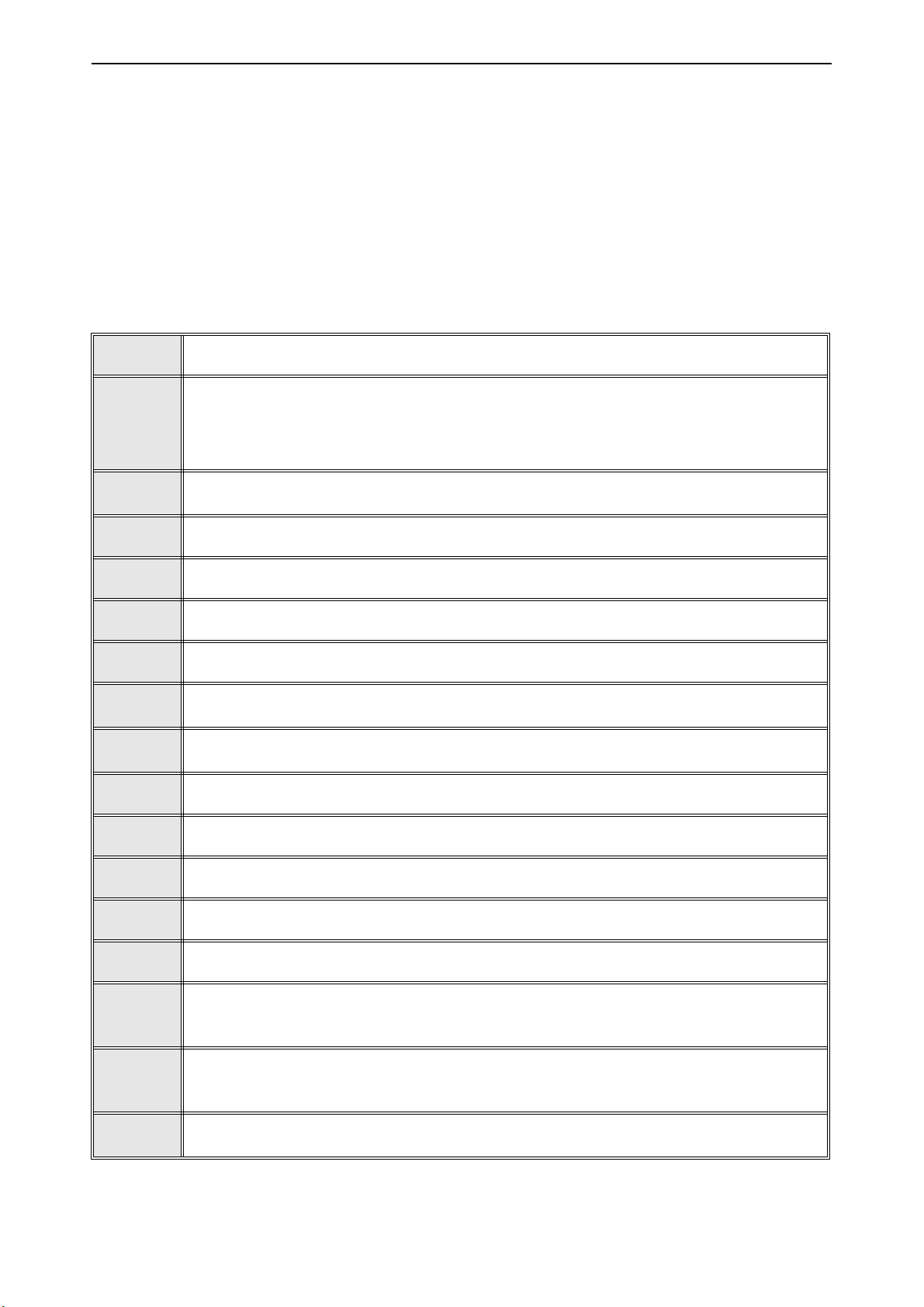
4.3 Mounting the cabinets
The cabinet should always be fixed to the floor or to the wall. Depending on installation conditions,
the cabinet sections can be fixed in different ways. There are holes in the front and back corners
which can be used for fixing. Additionally, the rails on the top of the cabinet have fixing lugs for fixing
the cabinet to the wall or to another cabinet.
4.3.1 Fixing the cabinet to the floor and wall
If the cabinet is installed against a wall, fix the top of the cabinet to the wall (1) and the front corners
to the floor (2) with bolts.
If bottom-only fixing is used, fix the cabinet to the floor in the front (2) and in the back (3) with bolts.
Fix all the cabinet sections in the same way.
Figure 13. Fixing the cabinet to the wall and floor
Local contacts: https://www.danfoss.com/en/contact-us/contacts-list/
Page 33

Installation vacon • 33
2 2
1
13862_00
4.3.2 Back-to-back installation
The sections can also be installed back-to-back. In this case, fix the top parts of the cabinets
together (1) and the front corners to the floor (2) with bolts.
Leave a gap between the backs of the cabinets. Check the correct dimensions from the documents
included in the delivery.
Figure 14. Fixing the cabinets back-to-back
Local contacts: https://www.danfoss.com/en/contact-us/contacts-list/
Page 34

vacon • 34 Installation
13864_00
DC
AC
PE
4.4 Connecting the busbars
The busbars are located in the back of the cabinets. To access them, it might be necessary to take
out the drives. See the instructions in Chapter 5.3.
Join together the DC, AC and PE busbars by bolting them together with baying brackets. The
mounting bolts, nuts and washers are delivered in place.
The busbars, size of the nuts and bolts differ case-by-case. See the correct tightening torque values
for different size bolts and different types of connections in Chapter 4.7.
4.4.1 Side-by-side connection
Figure 15. Connecting the common DC, AC and PE busbars
Local contacts: https://www.danfoss.com/en/contact-us/contacts-list/
Page 35

Installation vacon • 35
15599_00
15600_00
Figure 16. Connecting the common AC busbars in UL cabinets
4.4.2 Back-to-back connection
Figure 17. Connecting the common DC and PE busbars in back-to-back cabinet installation
Local contacts: https://www.danfoss.com/en/contact-us/contacts-list/
Page 36
vacon • 36 Installation
1
2
1
1
2
1
2
1
1
2
1
2
1
1
2
1
2
13863_00
4.5 Fixing the cabinet frames to each other
All the necessary parts for fixing the cabinet frames to each other are included in the delivery.
To join two cabinet sections to each other you need six quick-fit baying clamps (1 in figure below)
and four angular baying brackets (2 in figure). The four angular baying brackets are installed in the
top and bottom corners on the inside of the cabinet. Three of the quick-fit baying brackets are
installed in the front and three in the back on the outside of the cabinet.
Figure 18. Quick-fit baying clamps
Local contacts: https://www.danfoss.com/en/contact-us/contacts-list/
Page 37
Installation vacon • 37
9000.emf
4.6 Cabling
Before connecting any cables, use a multimeter to check that the cables to be
connected are not live.
4.6.1 Grounding
PE conductors are connected to the PE busbar. The PE busbars in each section are connected (see
Figure 15 on page 34) and the PE busbars must be connected to ground.
See the grounding and ground fault protection instructions in Chapter 2.3.
4.6.2 Mains and motor connection
The power supply terminals can be reached through the bottom part of the cabinet. The mains
cables are connected to terminals L1, L2 and L3 on the main input section (see Figure 19 on
page 38). The motor cables are connected to inverter section terminals marked with U, V and W.
Make openings for the cables in the grommets on the bottom of the cabinet and lead through the
cables. Use cable clamps to fix the cables.
Use cables with a temperature rating of at least +70°C. As a rule of thumb, cables and fuses can be
dimensioned according to the frequency converter nominal output current, which you can find on
the rating plate. Dimensioning according to the output current is recommended because the
frequency converter input current never significantly exceeds the output current.
Table 13. Cable types required to meet standards
Cable type
Level L
(2nd environment)
Level T
Mains cable 1 1
Motor cable 2 1/2*
Control cable 4 4
* Recommended
Level L =
EN61800-3, 2nd environment
Level T = For IT networks
1 =
Power cable intended for fixed installation and the specific mains voltage. Shielded
cable not required (DRAKA NK CABLES - MCMK or similar recommended).
Symmetrical power cable equipped with concentric protection wire and intended
2 =
for the specific mains voltage (DRAKA NK CABLES - MCMK or similar
recommended).
4 =
Screened cable equipped with compact low-impedance shield (DRAKA NKCABLES
- JAMAK, SAB/ÖZCuY-O or similar).
See the more detailed cabling and fuse selection instructions in the corresponding user manual
(see Chapter 1.5).
Local contacts: https://www.danfoss.com/en/contact-us/contacts-list/
Page 38
vacon • 38 Installation
L1
L2
L3
PE
PE
13865_00
U2, V2, W2
U1, V1, W1
PU1
PU2
PU3
U3, V3, W3
13866_00
Figure 19. Cabling of the main incoming section (MIS)
Figure 20. Cabling of inverter section IUS_4
Local contacts: https://www.danfoss.com/en/contact-us/contacts-list/
Page 39

Installation vacon • 39
U2, V2, W2
U1, V1, W1
PU1
PU2
13867_00
U
V
W
PE
13868_00
Figure 21. Cabling of inverter section IUS_6
Figure 22. Cabling of inverter section IUS_8
Local contacts: https://www.danfoss.com/en/contact-us/contacts-list/
Page 40

vacon • 40 Installation
U
V
W
PE
13869_00
U2
PU1 PU2
V2
W2
U1
V1
W1
PE
13870_00
Figure 23. Cabling of inverter sections IUS_9 and IUS_10
Figure 24. Cabling of inverter section IUS_12
Local contacts: https://www.danfoss.com/en/contact-us/contacts-list/
Page 41

Installation vacon • 41
U
V
W
PE
13871_00
Figure 25. Cabling of inverter section IUS_13
Local contacts: https://www.danfoss.com/en/contact-us/contacts-list/
Page 42
vacon • 42 Installation
15598_00
PE
+OCM
15601_00
U V W
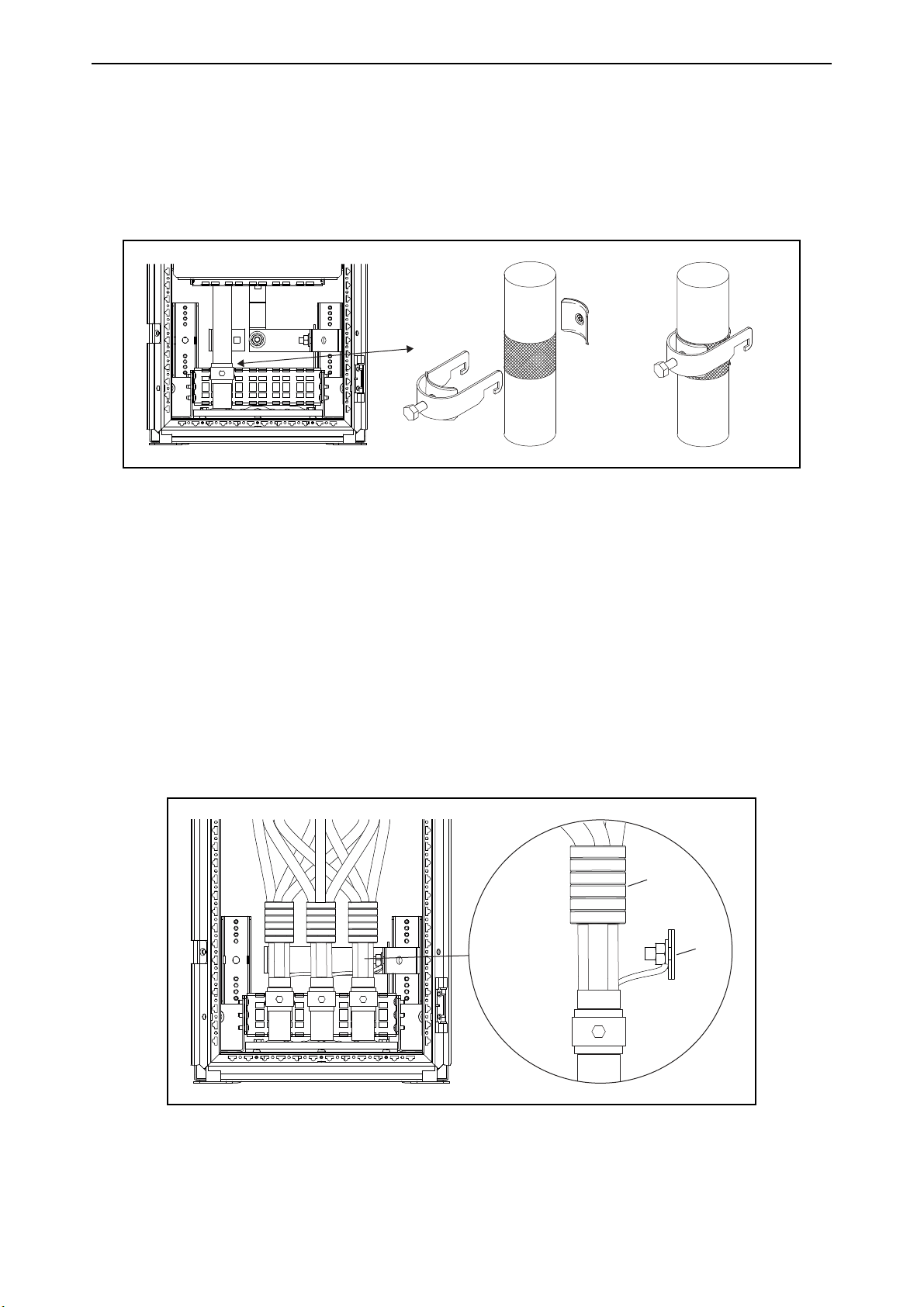
4.6.3 EMC grounding
For the EMC levels C1 and C2, it is necessary to have a 360º grounding of the shield on both ends of
the motor cable. The EMC grounding clamps must be suited to the output cable diameter to give a
360º contact with the cables. To make a 360° connection with the grounding clamp, expose the
shield of the motor cables.
Figure 26. 360º grounding
4.6.4 Installation of ferrite rings (+OCM) on the motor cable
Route only the motor phase conductors through the ferrite rings. Do not route the PE/ground wire
through the ferrite rings. Leave the cable screen below and outside the rings. Mount the PE/ground
wire or pigtail on the ground busbar.
In case of parallel motor cables, reserve an equal amount of ferrite ring sets for each cable. Route
all the phase conductors of one cable through one set of rings.
The delivery consists of fixed sets of ferrite rings (option). When ferrite rings are used to attenuate
the risk of bearing damage, always use two ferrite ring sets per motor cable.
NOTE! The ferrite rings are only additional protection. The basic protection against bearing currents
is an insulated bearing.
Figure 27. Installation of ferrite rings on motor cables
Local contacts: https://www.danfoss.com/en/contact-us/contacts-list/
Page 43

Installation vacon • 43
A BBCCDDE
E
A
13872_00
4.6.5 Control connections
The control unit of the AC drive consists roughly of the control board and additional boards
connected to the five slot connectors (A to E) of the control board. The control board is connected to
the power unit through a D-connector or fibre optic cables.
Usually, when the frequency converter is delivered from the factory, the control unit includes at least
the standard compilation of two basic boards (I/O board and relay board) which are normally
installed in slots A and B.
The control board can be powered externally (+24 V, ±10%) by connecting the external power source
to either of the bidirectional terminals. This voltage is sufficient for parameter setting and for
keeping the fieldbus active.
The tightening torques for the control unit terminals:
• Relay and thermistor terminals (screw M3): 0.5 Nm.
• Other terminals (screw M2.6): 0.2 Nm.
For more detailed cabling instructions, see the corresponding user manual (see Chapter 1.5).
Figure 28. Control unit, control board (right) and option boards (A-E)
Local contacts: https://www.danfoss.com/en/contact-us/contacts-list/
Page 44

vacon • 44 Installation
15604_00
4.6.6 Auxiliary low-voltage connections
The auxiliary low-voltage connections between cabinets can be done with wiring or with busbars.
For transport, the wires between two separately transported cabinets are disconnected from the
terminals. The wiring diagrams for the connections are delivered with the system drive.
Auxiliary low-voltage busbars (Auxigaine) are available as an option. In this case, the busbars of two
cabinets are connected with quick-connect bridge connectors. The bridge connectors are installed
by simply pressing them into place.
Figure 29. Installing the bridge connectors on the auxiliary low-voltage busbars
Local contacts: https://www.danfoss.com/en/contact-us/contacts-list/
Page 45
Installation vacon • 45
1
Grounding
braid
Rittal door
15553_UK
2
3
Rittal
frame
Rittal
8800490
Rittal
frame
1
15554_UK
Rittal
8800430
Rittal
frame
Rittal
M8 4163
1
15555_UK
Rittal
frame
Lifting
bar
1
2
15556_UK
Rittal
frame
UPGM
1
15557_UK
Rittal
frame
Fe
1
15558_UK
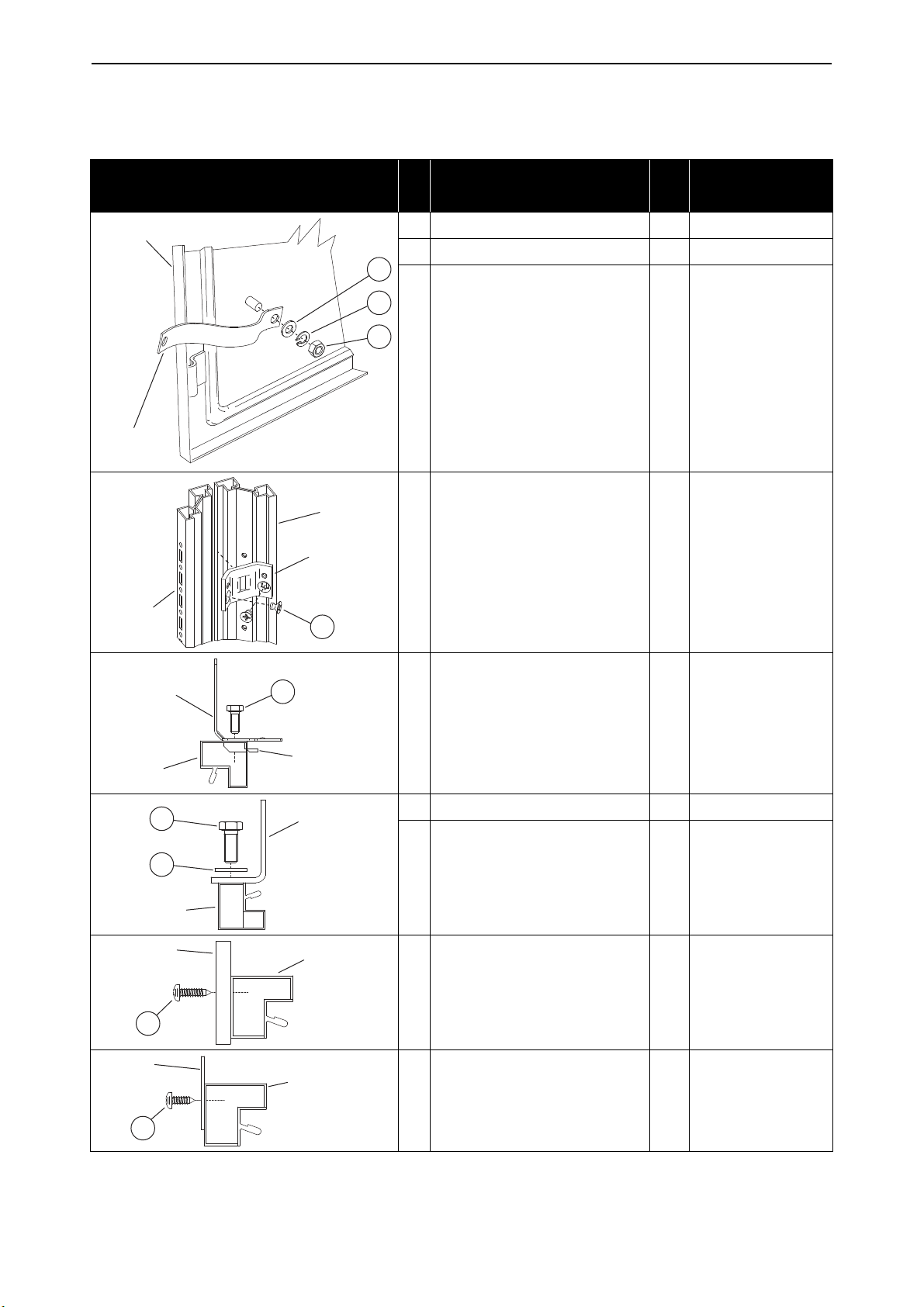
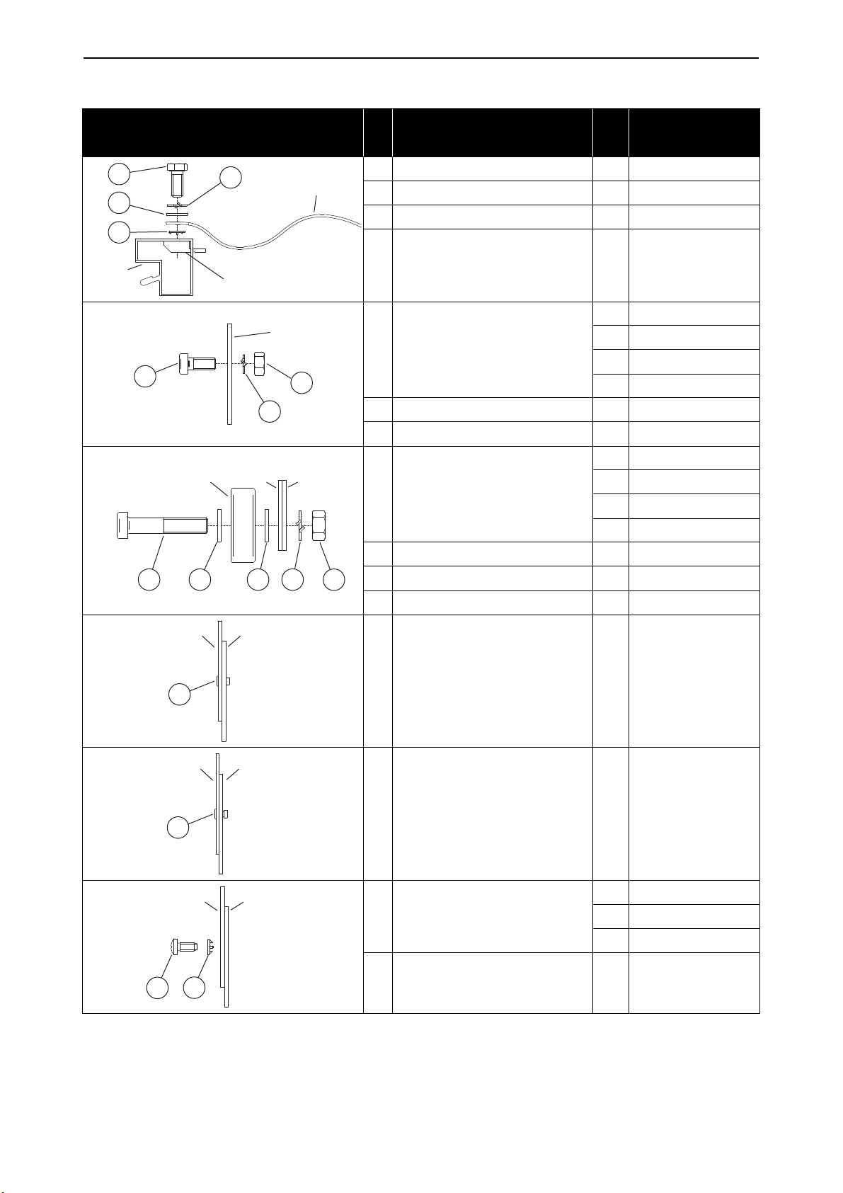
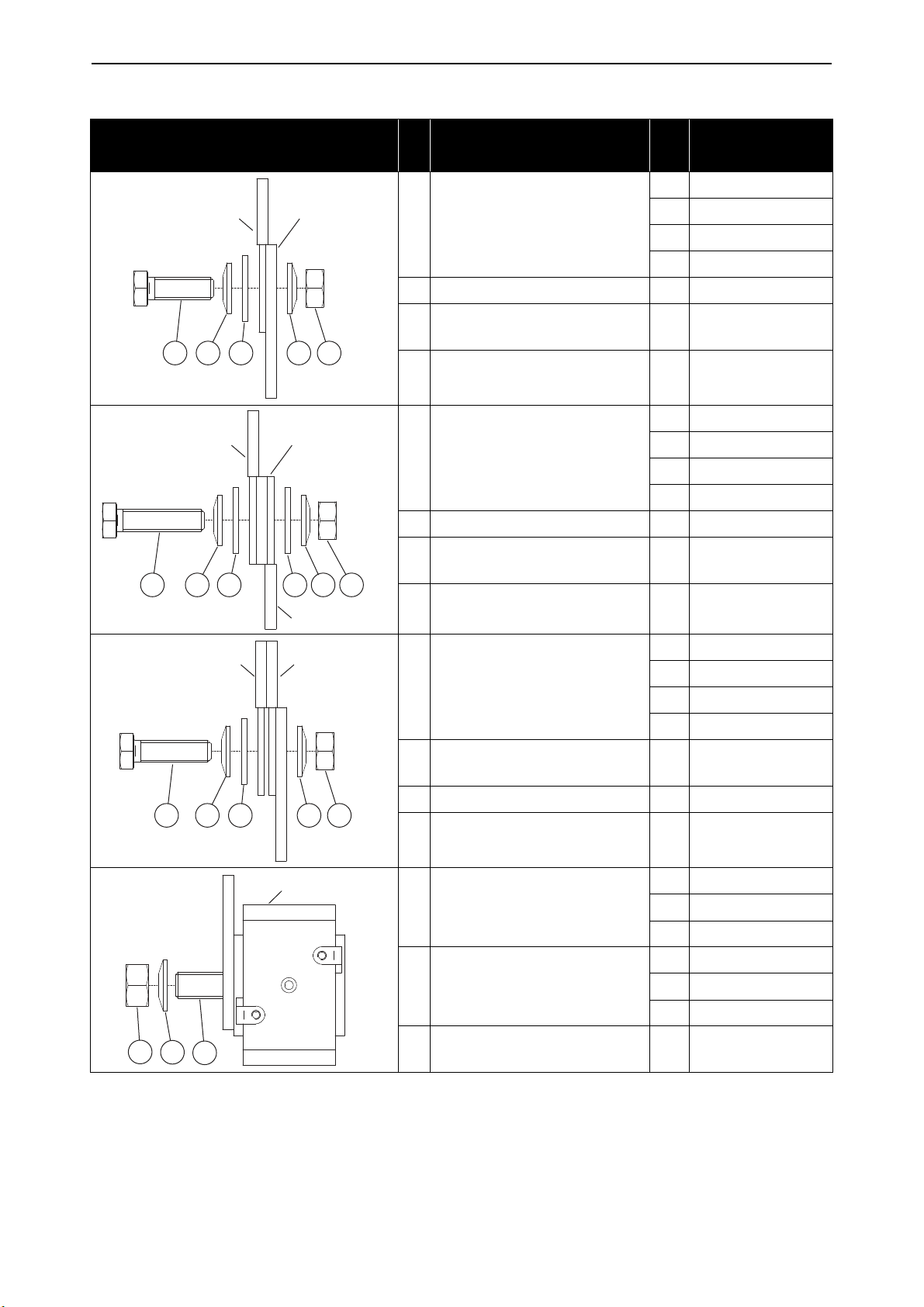
4.7 Screw tightening torques
Table 14. Tightening torques
Detail # Part Size
1 Plain washer, DIN 125 2 Spring washer, DIN 128 -
3 Nut, DIN 934 M8 10
Rittal tapered thread form-
1
ing screw M6x8
M6 9
Tightening torque
(Nm), ±15%
Rittal hex head bolt 8x16
1
with toothed neck
1 Hex head bolt, DIN 933 M12 20
2 Rittal IP rubber washer -
Self tapping screw,
1
DIN7049
Self tapping screw,
1
Local contacts: https://www.danfoss.com/en/contact-us/contacts-list/
DIN7049
M8 9
ST 5.5
5
ST 5.5
5
Page 46
vacon • 46 Installation
Grounding
braid
Rittal
Rittal
M8 4163
1
2
3
4
15559_UK
1
Fe
Hinge
2
3
15560_00
1
SKF
2 234
FeFe
15561_00
Bearing
1
FeFe
15562_00
1
FePVC
15563_00
2
Fe (painted)Fe (painted)
1
15564_UK
Table 14. Tightening torques
Detail # Part Size
1 Plain washer, DIN 125 2 Hex head bolt, DIN 933 M8 9
3 Toothed washer, DIN 6797 -
4 Spring washer, DIN 128 -
M6 6
M8 20
1 Socket head bolt, DIN 912
M10 40
M12 70
2 Spring washer, DIN 128 3 Nut, DIN 934 -
M6 6
M8 20
1 Socket head bolt, DIN 7984
M10 40
M12 70
Tightening torque
(Nm), ±15%
2 Plain washer, DIN 125 3 Nut, DIN 934 4 Spring washer, DIN 128 -
1 Rivet -
1 Rivet -
M4 1.5
Self-tapping screw,
1
DIN7500
M5 3
M6 6
2 Toothed washer, DIN 6797 -
Local contacts: https://www.danfoss.com/en/contact-us/contacts-list/
Page 47
Installation vacon • 47
1
FeFe
15565_00
1
FeUPGM
15566_00
1
23
Fe (holder)Fe
15567_UK
1
23
Fe (holder)PVC
15568_UK
1
FeFe
15569_00
1
2 4 3
FeFe
15570_00
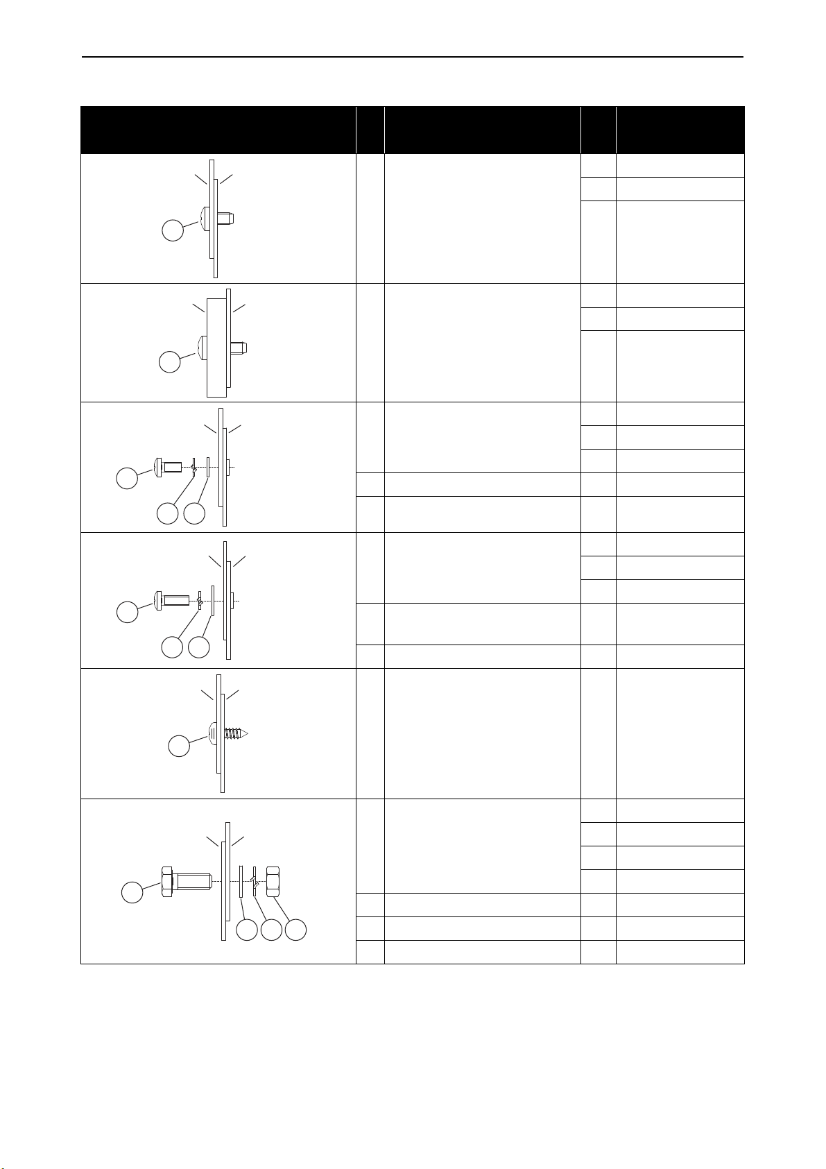
Table 14. Tightening torques
Detail # Part Size
M4 1.5
M5 3
Self-tapping screw,
1
DIN7500
M6 6
M4 1.5
M5 3
Self-tapping screw,
1
DIN7500
M6 6
M4 1.5
1 Screw, DIN 7045
M5 3
M6 6
2 Plain washer, DIN 125 -
3 Spring washer, DIN 128 -
Tightening torque
(Nm), ±15%
M4 1.5
1 Screw, DIN 7045
M5 3
M6 6
Plain washer large,
2
DIN9021
3 Spring washer, DIN 128 -
Self-tapping screw,
1
DIN7049
ST 5.5
M6 6
M8 20
1 Hex head bolt, DIN 933
M10 40
M12 70
2 Plain washer, DIN 125 3 Nut, DIN 934 -
-
5
4 Spring washer, DIN 128 -
Local contacts: https://www.danfoss.com/en/contact-us/contacts-list/
Page 48

vacon • 48 Installation
1 3 44 3 2
FeFe
15571_00
1 4 2
FeFe
3
15572_00
1 4
5 3 2
FeCable gland
15573_UK
1
1
Socomec
SB205
15574_00
1 2 4 3
FeSocomec
SB205
15575_00
Table 14. Tightening torques
Detail # Part Size
M6 6
M8 20
1 Hex head bolt, DIN 933
M10 40
M12 70
2 Nut, DIN 934 3 Plain washer, DIN 125 4 Spring washer, DIN 128 -
M6 6
M8 20
1 Hex head bolt, DIN 933
M10 40
M12 70
2 Plain washer, DIN 125 3 Press nut 4 Spring washer, DIN 128 1 Hex head bolt, DIN 933 M8 2
2 Nut, DIN 934 3 Plain washer, DIN 125 -
Tightening torque
(Nm), ±15%
Plain washer large,
4
DIN9021
-
5 Spring washer, DIN 128 -
1 Hex head bolt, DIN 933 M8 10
1 Hex head bolt, DIN 933 M8 10
2 Plain washer, DIN 125 3 Nut, DIN 934 -
4 Spring washer, DIN 128 -
Local contacts: https://www.danfoss.com/en/contact-us/contacts-list/
Page 49

Installation vacon • 49
1
Socomec SB205
15576_00
132
Socomec
SB205
Cu
15577_00
21
IS40-8SCu
15578_00
IS40-8SFe
21
15579_00
IC20Cu
21
15580_00
Table 14. Tightening torques
Detail # Part Size
1 Hex head bolt, DIN 933 M8 10
1 Hex head bolt, DIN 933 M8 10
2 Nut, DIN 934 -
Conical spring washer,
3
DIN6796
Tightening torque
(Nm), ±15%
-
M6 6
M8 20
1 Hex head bolt, DIN 933
M10 40
M12 70
Conical spring washer,
2
DIN6796
M6 6
M8 20
1 Hex head bolt, DIN 933
M10 40
M12 70
2 Spring washer, DIN 128 -
M6 6
M8 20
1 Hex head bolt, DIN 933
M10 40
M12 70
Conical spring washer,
2
DIN6796
-
-
Local contacts: https://www.danfoss.com/en/contact-us/contacts-list/
Page 50

vacon • 50 Installation
IC20Fe
1 2
15581_00
31
Cu Cu
23
15582_00
Cu Fe
31 23
15583_00
Cu UPGM
41 5 32
15584_00
Table 14. Tightening torques
Detail # Part Size
M6 6
M8 20
1 Hex head bolt, DIN 933
M10 40
M12 70
2 Spring washer, DIN 128 -
M6 6
M8 20
1 Hex head bolt, DIN 933
M10 40
M12 70
2 Nut, DIN 934 -
Conical spring washer,
3
DIN6796
M6 6
M8 20
1 Hex head bolt, DIN 933
M10 40
Tightening torque
(Nm), ±15%
-
M12 70
2 Nut, DIN 934 -
Conical spring washer,
3
DIN6796
M6 6
M8 20
1 Hex head bolt, DIN 933
M10 40
M12 70
2 Plain washer, DIN 125 3 Nut, DIN 934 -
Conical spring washer,
4
DIN6796
5 Spring washer, DIN 128 -
-
-
Local contacts: https://www.danfoss.com/en/contact-us/contacts-list/
Page 51
Installation vacon • 51
Flexibar Cu
341 24
15585_UK
Flexibar Cu
Flexibar
341 4 23
15586_UK
Flexibar Flexibar
241 34
15587_UK
3
1
2
Ferraz 33 TTF
15588_00
Table 14. Tightening torques
Detail # Part Size
M6 6
M8 20
1 Hex head bolt, DIN 933
M10 40
M12 70
2 Nut, DIN 934 -
Plain washer large,
3
DIN9021
Conical spring washer,
4
DIN6796
M6 6
M8 20
1 Hex head bolt, DIN 933
M10 40
M12 70
2 Nut, DIN 934 -
Plain washer large,
3
DIN9021
Tightening torque
(Nm), ±15%
-
-
-
Conical spring washer,
4
DIN6796
M6 6
M8 20
1 Hex head bolt, DIN 933
M10 40
M12 70
Plain washer large,
2
DIN9021
3 Nut, DIN 934 -
Conical spring washer,
4
DIN6796
M8 10
1 Stud, DIN 913
M10 15
M12 15
M8 13.5
2 Nut, DIN 934
M10 26
M12 46
Conical spring washer,
3
DIN6796
-
-
-
-
Local contacts: https://www.danfoss.com/en/contact-us/contacts-list/
Page 52

vacon • 52 Installation
44 TTQF
3
1
2
15589_00
83 TTQ
3 12
15590_00
84 TTQF
3
1
2
15591_00
3 21
CuCu
15592_00
Table 14. Tightening torques
Detail # Part Size
M8 10
1 Stud, DIN 913
M10 15
M12 15
M8 13.5
2 Nut, DIN 934
M10 26
M12 46
Conical spring washer,
3
DIN6796
M8 10
1 Stud, DIN 913
M10 15
M12 15
M8 13.5
2 Nut, DIN 934
M10 26
M12 46
Conical spring washer,
3
DIN6796
Tightening torque
(Nm), ±15%
-
-
M8 10
1 Stud, DIN 913
M10 15
M12 15
M8 13.5
2 Nut, DIN 934
M10 26
M12 46
Conical spring washer,
3
DIN6796
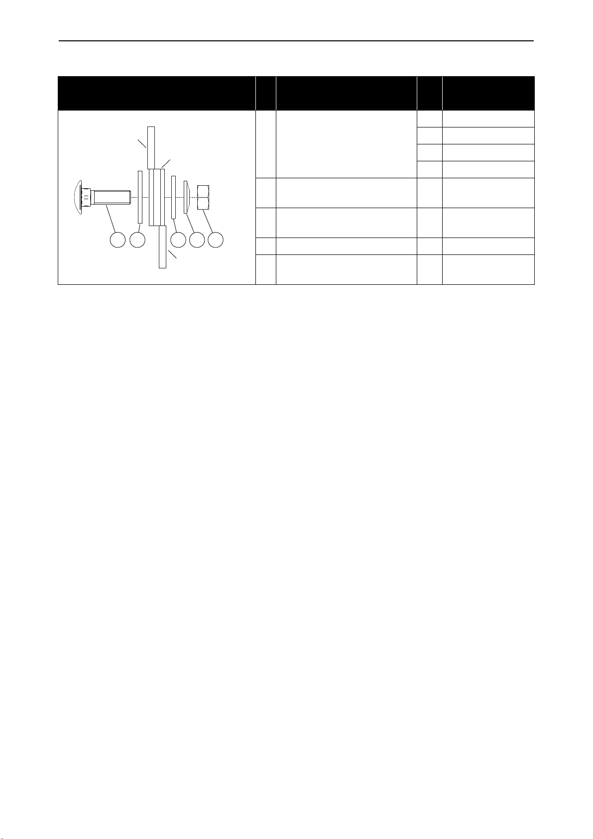
M6 6
Cup square neck bolt,
1
DIN603
M8 20
M10 40
M12 70
2 Nut, DIN 934 -
Conical spring washer,
3
DIN6796
-
-
Local contacts: https://www.danfoss.com/en/contact-us/contacts-list/
Page 53

Installation vacon • 53
CuCu
2 4 31
Cu
15593_00
FeCu
3 21
15594_00
UPGM
Cu
2 4 31
15595_00
Cu
Flexibar
4 231
15596_UK
Table 14. Tightening torques
Detail # Part Size
M6 6
Cup square neck bolt,
1
DIN603
M8 20
M10 40
M12 70
Plain washer large,
2
DIN9021
3 Nut, DIN 934 -
Conical spring washer,
4
DIN6796
M6 6
Cup square neck bolt,
1
DIN603
M8 20
M10 40
M12 70
2 Nut, DIN 934 -
Tightening torque
(Nm), ±15%
-
-
Conical spring washer,
3
DIN6796
M6 6
Cup square neck bolt,
1
DIN603
M8 20
M10 40
M12 70
2 Plain washer, DIN 125 3 Nut, DIN 934 4 Spring washer, DIN 128 -
M6 6
Cup square neck bolt,
1
DIN603
M8 20
M10 40
M12 70
2 Nut, DIN 934 -
Plain washer large,
3
DIN9021 (1 size bigger)
Conical spring washer,
4
DIN6796
-
-
-
Local contacts: https://www.danfoss.com/en/contact-us/contacts-list/
Page 54
vacon • 54 Installation
Cu
Flexibar
Flexibar
3 5 421
15597_UK
Table 14. Tightening torques
Detail # Part Size
M6 6
Cup square neck bolt,
1
DIN603
M8 20
M10 40
M12 70
Plain washer large,
2
DIN9021 (1 size bigger)
Plain washer large,
3
DIN9021
4 Nut, DIN 934 -
Conical spring washer,
5
DIN6796
Tightening torque
(Nm), ±15%
-
-
-
Local contacts: https://www.danfoss.com/en/contact-us/contacts-list/
Page 55

Service vacon • 55
5. S
ERVICE
5.1 Warranty
Only manufacturing defects are covered by the warranty. The manufacturer assumes no
responsibility for damages caused during or resulting from transport, receipt of the delivery,
installation, commissioning or use.
The manufacturer shall in no event and under no circumstances be held responsible for damages
and failures resulting from misuse, wrong installation, unacceptable ambient temperature, dust,
corrosive substances or operation outside the rated specifications.
Neither can the manufacturer be held responsible for consequential damages.
The Manufacturer's warranty period is 18 months from the delivery or 12 months from the
commissioning whichever expires first (Danfoss general terms and conditions of sale).
The local distributor may grant a warranty time different from the above. This warranty time shall
be specified in the distributor's sales and warranty terms. Danfoss assumes no responsibility for
any other warranties than that granted by Danfoss itself.
In all matters concerning the warranty, please contact your distributor first.
5.2 Maintenance
All technical devices, drives as well, need a certain amount of care-taking and failure preventive
maintenance. To maintain trouble-free operation of the VACON® drives, environmental conditions,
as well as load, line power, process control, etc. have to be within specifications, determined by
manufacturer.
If all conditions are in accordance with the manufacturer's specifications, there are no other
concerns, but to provide a cooling capacity high enough for the power- and control circuits. This
requirement can be met by making sure, that the cooling system works properly. Operation of
cooling fans and cleanness of the heat sink should be verified regularly.
Regular maintenance is recommended to ensure trouble free operation and long lifetime of the
VACON® drives. At least the following things should be included in the regular maintenance.
Table 15. Maintenance schedule
Interval Maintenance
12 months (if unit is stored) Reform the capacitors
Check the tightening torques of the input and output terminals
6-24 months (depending on
environment)
5-7 years
and I/O terminals.
Clean the cooling tunnel.
Check operation of the cooling fan, check for corrosion on terminals, busbars and other surfaces.
Change the cooling fans:
• Cabinet fans
• Drive fans
• LCL filter fans
5-10 years Change the DC-link capacitors if DC voltage ripple is high.
It is also recommended to record all actions and counter values with dates and time for follow up of
maintenance.
Local contacts: https://www.danfoss.com/en/contact-us/contacts-list/
Page 56

vacon • 56 Service
13006.emf
13929_00
X
X
X
X
13930_00
5.3 Removing the drives from the cabinet
Servicing is only permitted to be carried out by Danfoss-trained service personnel!
5.3.1 IUS_4 / IUS_6
1
2
3
Open the cabinet door.
Disconnect all cables from the drive. See Chapter 4.6.
Release the drive assembly. Remove the four M8x20 bolts (tightening torque 20Nm).
Figure 30. Drive assembly mounting bolts (X) in IUS_4 (left) and IUS_6 (right)
Pull out the drive assembly.
4
Figure 31. Pulling the drive assembly in IUS_4 (left) and IUS_6 (right)
Local contacts: https://www.danfoss.com/en/contact-us/contacts-list/
Page 57
Service vacon • 57
13931_00
X
X
13932_00
5.3.2 IUS_7 / IUS_8
1
2
Open the cabinet door.
Release the drive assembly. Remove the five M8x20 bolts (tightening torque 20Nm).
3
Figure 32. Drive assembly mounting bolts (X)
Pull out the drive assembly.
Figure 33. Pulling the drive assembly out of the cabinet
4
Local contacts: https://www.danfoss.com/en/contact-us/contacts-list/
Disconnect all cables from the drive. See Chapter 4.6.
Page 58
vacon • 58 Service
13877_00
±5mm
3
2
1
13878_00
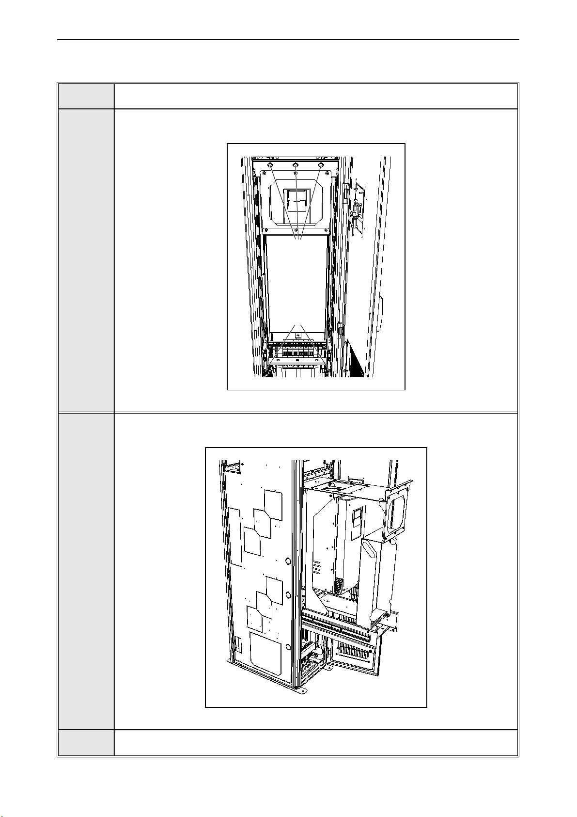
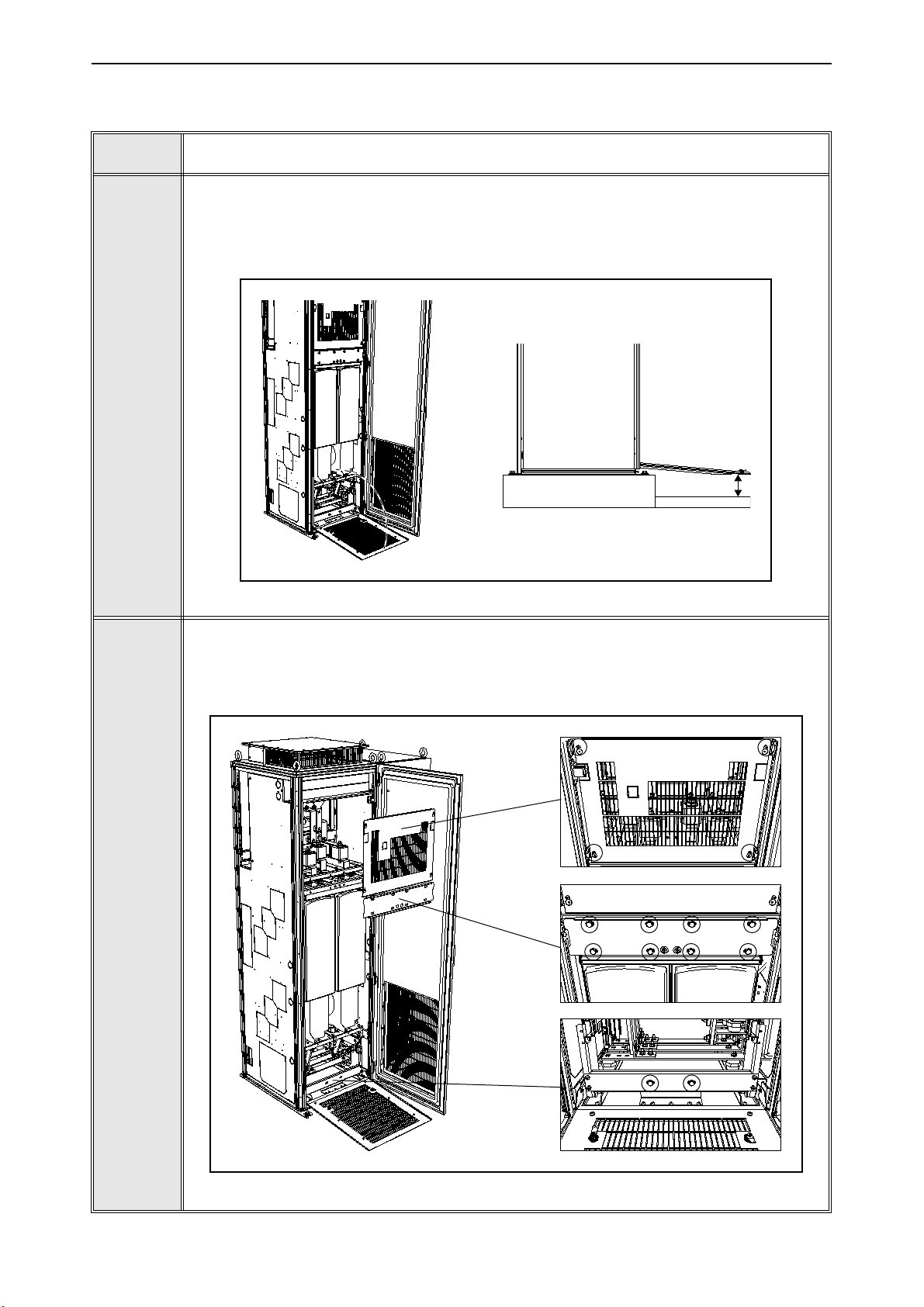
5.3.3 IUS_9 / IUS_10
1
2
Open the cabinet door.
Release the service ramp and turn it down in front of the drive.
NOTE! The height of the surface in front of the cabinet should not differ more than
5mm from the level of the cabinet installation.
Figure 34. Lowering the service ramp
3
1. Loosen the four M5 screws (tightening torque 3Nm) and remove the touch cover.
2. Remove the six M8 screws (torque 20 Nm) and remove the upper holder plate.
3. Remove the two M8 screws (torque 20 Nm) from the drive bottom holder plate.
Figure 35. Removing the drive touch cover and holder plates
Local contacts: https://www.danfoss.com/en/contact-us/contacts-list/
Page 59

Service vacon • 59
13912_00
1
3 3
2
13879_00
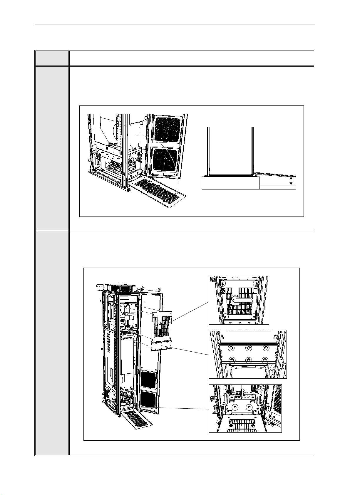
Release the input busbar assemblies. Remove:
1. two M10 nuts and M10x30 bolts (torque 40 Nm) from the upper busbars,
2. two M12 nuts and M12x40 bolts (torque 70 Nm) from the lower busbars,
3. two M8x20 screws (torque 20 Nm) from the back plate.
Take out the busbar assemblies, including the fuses.
4
5
Figure 36. Releasing the input busbar assembly
Release the output busbars. Remove three M10 nuts/bolts (tightening torque 40Nm).
Figure 37. Busbar mounting screws
Local contacts: https://www.danfoss.com/en/contact-us/contacts-list/
Page 60
vacon • 60 Service
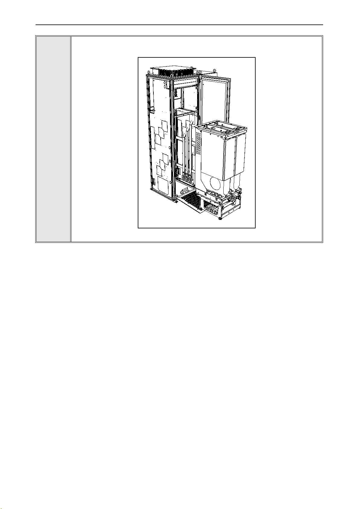
13880_00
Pull the drive out on the service ramp.
6
Figure 38. Pulling the drive out of the cabinet
Local contacts: https://www.danfoss.com/en/contact-us/contacts-list/
Page 61
Service vacon • 61
13933_00
±5mm
13934_00
3
2
1
5.3.4 IUS_12
1
2
Open the cabinet door.
Release the service ramp and turn it down in front of the drive.
NOTE! The height of the surface in front of the cabinet should not differ more than
5mm from the level of the cabinet installation.
Figure 39. Lowering the service ramp
3
1. Loosen the four M5 screws (tightening torque 3 Nm) and remove the touch cover.
2. Remove the eight M8 screws (torque 20 Nm) and remove the upper holder plate.
3. Remove the two M8 screws (torque 20 Nm) from the drive bottom holder plate.
Figure 40. Removing the drive touch cover and holder plates
Local contacts: https://www.danfoss.com/en/contact-us/contacts-list/
Page 62

vacon • 62 Service
13935_00
1
3
3
1
2
2
13936_00
Release the input busbar assembly. Remove:
1. four M10 nuts and M10x30 bolts (torque 40 Nm) from the upper busbars,
2. four M12 nuts and M12x40 bolts (torque 70 Nm) from the lower busbars,
3. two M8x20 screws (torque 20 Nm) from the back plate.
Take out the busbar assemblies, including the fuses.
4
5
Figure 41. Releasing the input busbar assembly
Release the output busbars. Remove six M10 nuts/bolts (tightening torque 40 Nm).
Figure 42. Output busbar mounting screws
Local contacts: https://www.danfoss.com/en/contact-us/contacts-list/
Page 63
Service vacon • 63
13937_00
Pull the drive out on the service ramp.
6
Figure 43. Pulling the drive out of the cabinet
Local contacts: https://www.danfoss.com/en/contact-us/contacts-list/
Page 64

vacon • 64 Service
13938_00
±5mm
13939_00
3
2
1
5.3.5 IUS_13 / IUS_14
1
2
Open the cabinet door.
Release the service ramp and turn it down in front of the drive.
NOTE! The height of the surface in front of the cabinet should not differ more than
5mm from the level of the cabinet installation.
Figure 44. Lowering the service ramp
1. Loosen the four M5 screws (tightening torque 3 Nm) and remove the touch cover.
2. Remove the eight M8 screws (torque 20 Nm) and remove the upper holder plate.
3. Remove the four M8 screws (torque 20 Nm) from the drive bottom holder plate.
3
Figure 45. Removing the drive touch cover and holder plates
Local contacts: https://www.danfoss.com/en/contact-us/contacts-list/
Page 65

Service vacon • 65
13940_00
1
3
1
1
2
2
2
3
13941_00
Release the input busbar assembly. Remove:
1. six M10 nuts and M10x30 bolts (torque 40 Nm) from the upper busbars,
2. six M12 nuts and M12x40 bolts (torque 70 Nm) from the lower busbars,
3. two M8x20 screws (torque 20 Nm) from the back plate.
Take out the busbar assemblies, including the fuses.
4
5
Figure 46. Releasing the input busbar assembly
Release the output busbars. Remove three M12 nuts/bolts (tightening torque 70Nm).
Figure 47. Output busbar mounting screws
Local contacts: https://www.danfoss.com/en/contact-us/contacts-list/
Page 66

vacon • 66 Service
13942_00
Pull the drive out on the service ramp.
6
Figure 48. Pulling the drive out of the cabinet
Local contacts: https://www.danfoss.com/en/contact-us/contacts-list/
Page 67

Technical information vacon • 67
6. T
ECHNICAL INFORMATION
6.1 Control and interface
Speed and/or torque control functions are available in the drive. Speed and/or torque reference as
well as command word is generated by the overriding line control system and individually
transmitted to each drive either via fieldbus or hardwired signals. The drive transmits selected
actual values as well as status words back to the line control system.
6.1.1 Control without speed feedback (open loop)
• Speed error in steady state typically <0.5%
• Torque rise time <10 ms
• Torque error in steady state typically <3%
• Suitable also for multimotor configuration
6.1.2 Control with speed feedback (closed loop)
Full torque control at zero speed cannot be maintained without speed feedback. When a speed error
of less than 0.5% or full torque control at all speeds is required, motor control based on feedback
from an encoder is a necessity. This capability is incorporated into the VACON® NXP drive. In
addition to the current measurement system used, the NXP drive utilizes feedback values from the
encoder to determine the motor state. The enhanced microprocessor provided with the NXP drive
is capable of calculations every 150 microseconds. This control can be used for applications
requiring high precision, such as sectional drives.
• Speed error in steady state typically <0.01% (pulse encoder type dependent)
• Pulse encoder: 250-5000 ppr at 5, 12 or 24 V (option board dependent)
• Torque rise time <10 ms
• Torque error in steady state typically <3%
6.2 Load definitions
The drives are normally selected based on the load definition shown in the drive list, where:
•
n
= minimum speed [RPM], beginning of the continuous constant torque load speed
min
range
•
n
= base speed [RPM], end of the continuous constant torque load speed range (and
base
beginning of the continuous constant power load speed range)
•
n
= maximum speed [RPM], end of the continuous constant power load speed range (also
max
maximum allowed motor speed)
•P [
n
] = base power [kW], motor shaft power at the end of the continuous constant torque
base
load speed range (also motor shaft power of the continuous constant power load speed
range)
•T [
n
] = base torque [Nm], motor shaft torque of the continuous constant torque load
base
speed range (also motor shaft torque at the beginning of the continuous constant power
load speed range)
•
OL
= overload [%], short time maximum load, 1 min. / 10 min. (100% = no overload)
NOTE! Load is defined based on the information received. Danfoss is not responsible for verifying
that the information is sufficient and accurate.
There are various possibilities to define the load curve. Below are some examples.
Local contacts: https://www.danfoss.com/en/contact-us/contacts-list/
Page 68
vacon • 68 Technical information
0
100
200
300
400
500
600
700
800
0 200 400 600 800 1000 1200 1400 1600
cont. load
max load
Speed [rpm]
Tor que [Nm ]
13886_UK
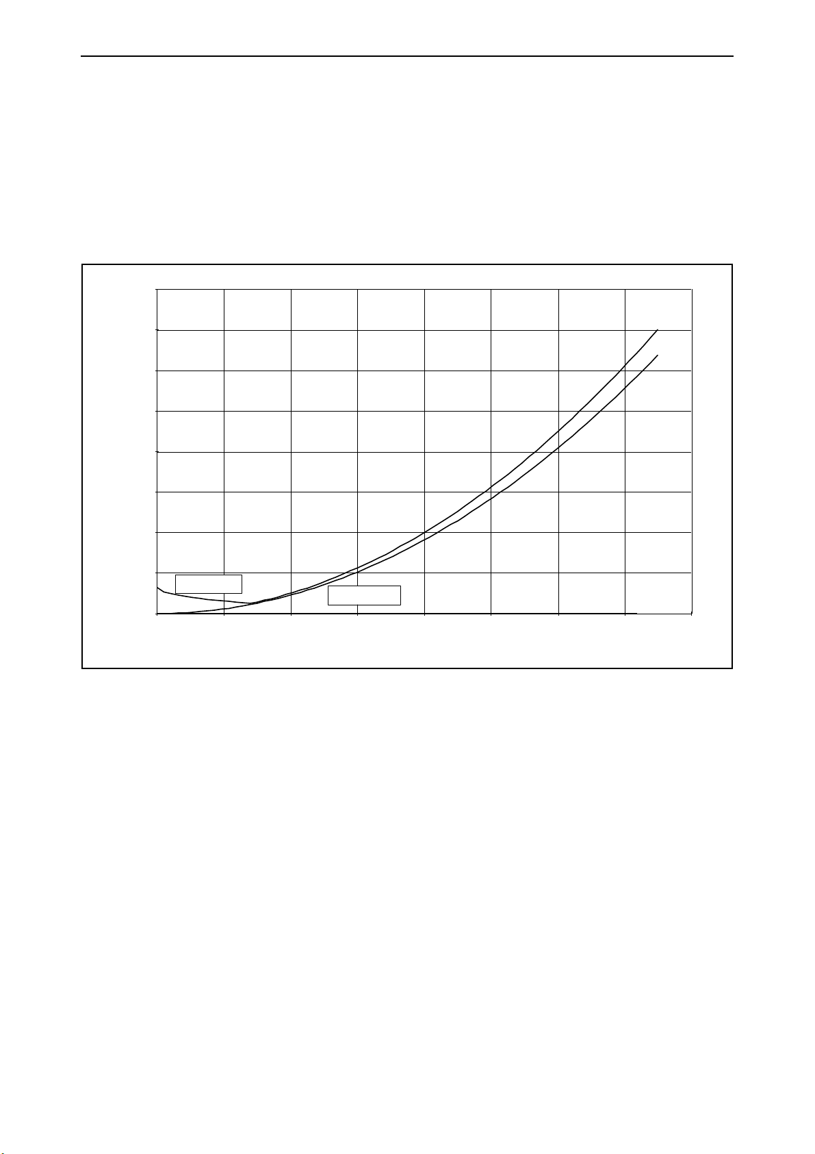
6.2.1 Pump and fan load
Set all speeds to the same value (
n
min
=
n
base
=
n
) to have the typical pump and fan curve, i.e.
max
quadratically increasing load.
The overload is now set as starting torque and as OL at maximum speed (the overload is now defined
as percent of torque at maximum speed).
The calculation of current is also here done assuming nominal flux in the motor from 0 to field
weakening point (current calculation according to ”optimized flux curve” is not available).
Figure 49. Example: pump and fan load
Local contacts: https://www.danfoss.com/en/contact-us/contacts-list/
Page 69
Technical information vacon • 69
0
200
400
600
800
1000
1200
0 200 400 600 800 1000 1200 1400 1600
cont. load
max load
Speed [rpm]
Tor que [Nm ]
13887_UK
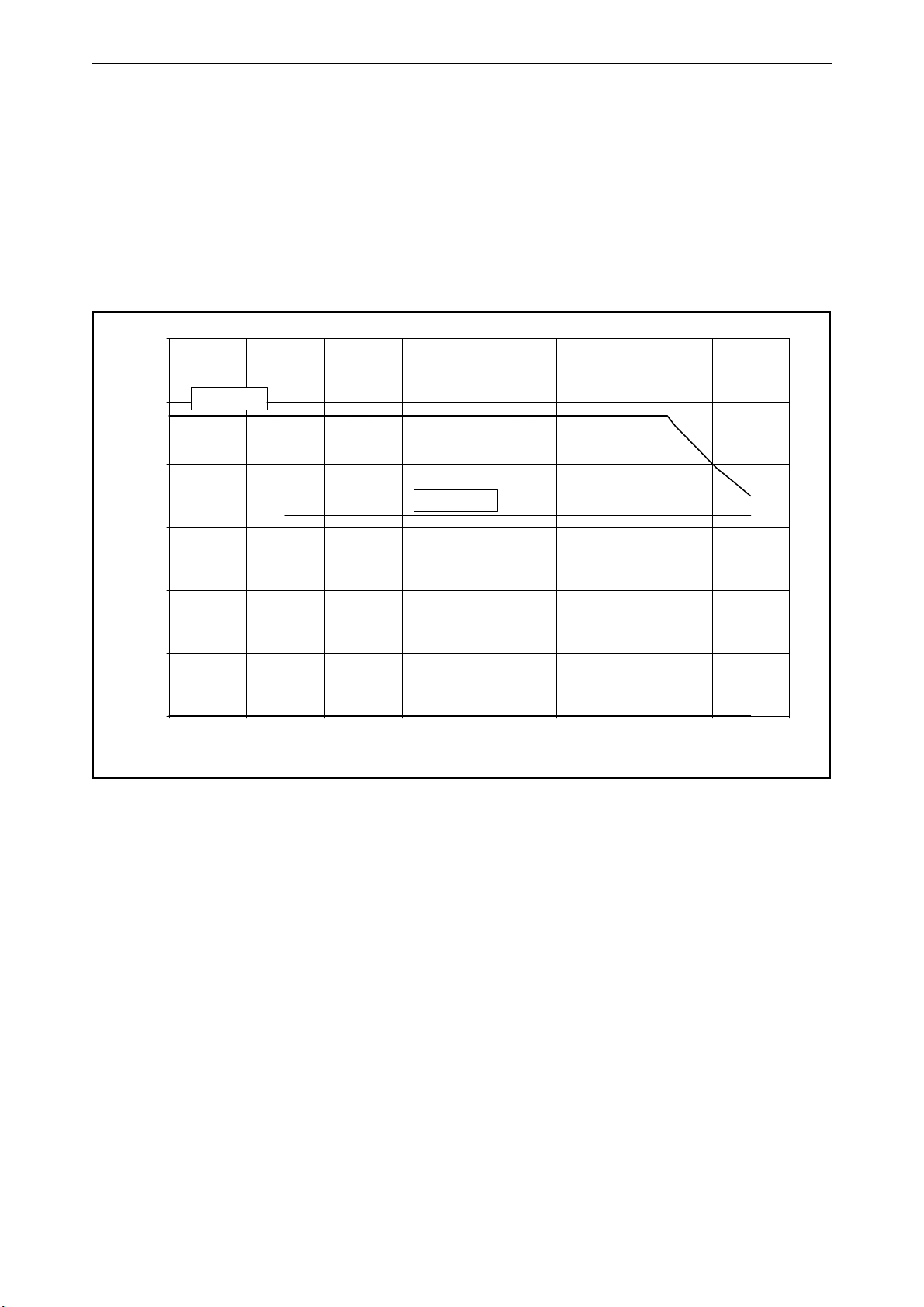
6.2.2 OL(
n
base
) > OL(
n
) for constant torque load
max
It is possible to set the overload at base speed smaller than the overload at maximum speed, i.e.
OL(
n
base
) < OL(
n
max
).
This can be useful when selecting the correct AC drive for constant torque drives where the overload
demand at low speeds is higher than at high speeds.
This possibility is usually used when the field weakening point is higher than base speed.
The benefit from this can be the possibility to use a size smaller AC drive.
Figure 50. Example: OL(n
base
) > OL(n
) for constant torque load
max
Local contacts: https://www.danfoss.com/en/contact-us/contacts-list/
Page 70

vacon • 70 Technical information
0
200
400
600
800
1000
1200
0 200 400 600 800 1000 1200 1400 1600
cont. load
max load
Speed [rpm]
Tor que [Nm ]
13888_UK
6.2.3 Starting torque >> OL(
It is possible to set the starting torque higher than the overload at maximum speed, i.e. OL(
OL(
n
).
max
n
) for constant torque load
max
n
base
) <
This can be useful when selecting the correct AC drive for constant torque drives where the starting
torque requirement is much higher than the maximum load requirement at maximum speed.
This possibility is usually used when the field weakening point is higher than base speed and when
the starting torque is needed for a very short time.
The benefit from this can be the possibility to use a size smaller AC drive.
Figure 51. Example: Starting torque >> OL(n
) for constant torque load
max
Local contacts: https://www.danfoss.com/en/contact-us/contacts-list/
Page 71

Technical information vacon • 71
0
50 0
10 00
15 00
20 00
25 00
30 00
35 00
0 200 400 600 8 00 10 00 120 0 140 0 160 0
cont. load
max load
Speed [rpm]
Tor que [Nm ]
13889_UK
6.2.4 OL(
n
base
) > OL(
n
) for constant power load
max
Some constant power drives require less overload at max speed than at lower speeds. It is therefore
possible to set the relative overload at base speed higher than the relative overload at maximum
speed, i.e. OL(
n
base
) > OL(
n
max
).
This will decrease the size of the motor when/if thermal loadability is not the dimensioning limit.
Figure 52. Example: OL(n
base
) > OL(n
) for constant power load
max
Local contacts: https://www.danfoss.com/en/contact-us/contacts-list/
Page 72
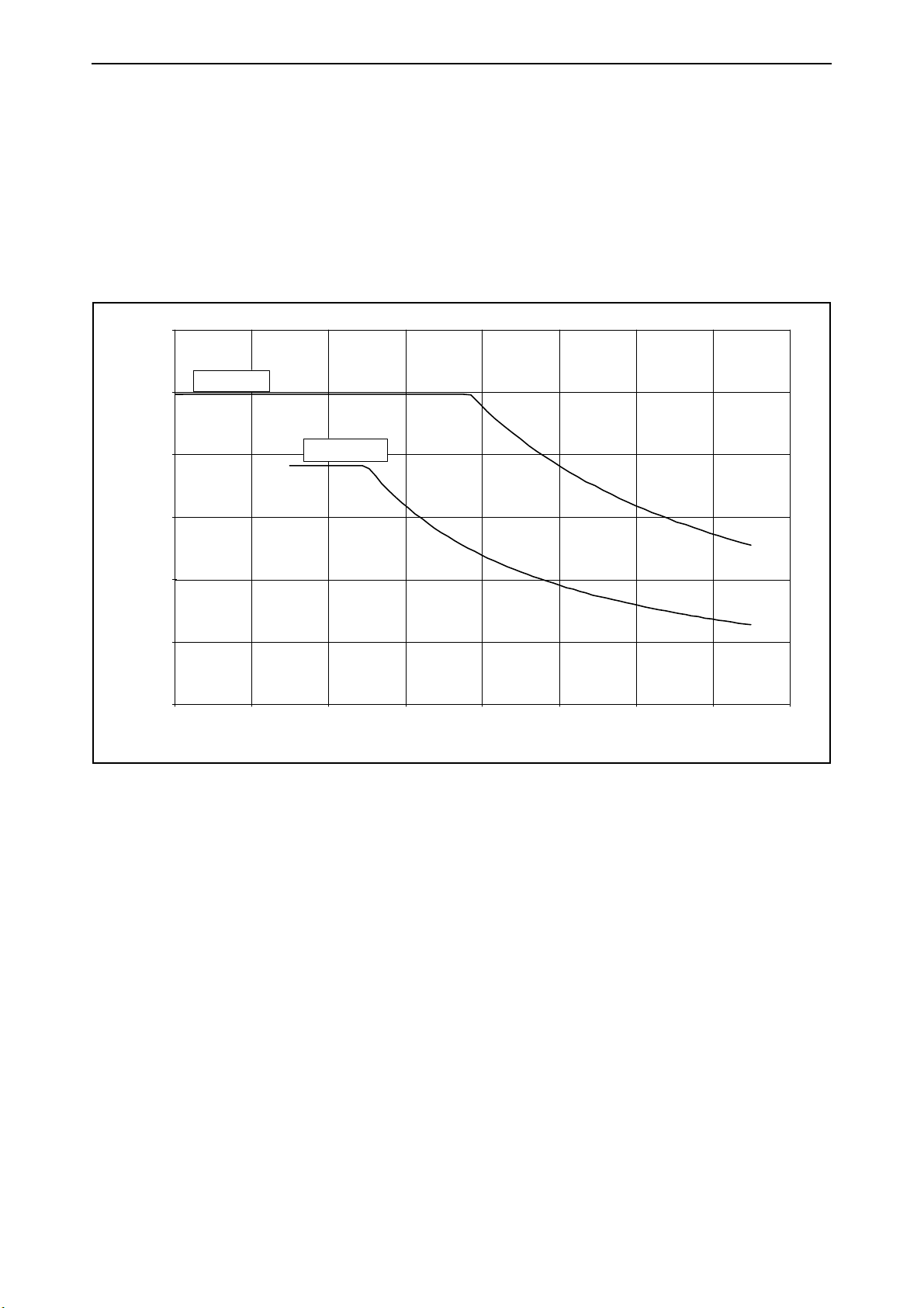
vacon • 72 Technical information
0
500
100 0
150 0
200 0
250 0
300 0
0 200 40 0 6 00 800 10 00 1200 14 00 1600
cont. load
max load
Speed [rpm]
Tor que [Nm ]
13890_UK
6.2.5 OL(
It is possible to set the overload at base speed smaller than the overload at max speed, i.e. OL(
< OL(
n
max
n
base
) < OL(
n
) for constant power load
max
n
base
).
This can be useful when selecting the correct motor and AC drive for constant power drives where
the relative OL requirement is higher at maximum speed than the relative OL requirement at base
speed.
The benefit from this can be the possibility to use a size smaller AC drive.
)
Figure 53. Example: OL(n
base
) < OL(n
) for constant power load
max
Local contacts: https://www.danfoss.com/en/contact-us/contacts-list/
Page 73

Technical information vacon • 73
6.3 Technical specifications for VACON® drives
6.3.1 NXN - Non-regenerative front end units
Table 16. Technical specifications for non-regenerative front-end (NFE) drives
Mains
connection
DC connection
Control
characteristics
Input voltage U
in
Input frequency f
in
380-690 V AC; -15%...+10%, EN 60204-1
45-66 Hz
IH: Ambient temperature max. +40°C,
overloadability 1.5 x IH (1 min./10 min.)
Continuous input current
IL: Ambient temperature max. +40°C,
overloadability 1.1 x IL (1 min./10 min.)
Connection to mains Unlimited (internal overload protections)
Current THD Depends on additional chokes (normal case < 40%)
Starting delay Depend on DC bus capacitance (max. 10 s)
Shorter breaks than 40 ms work normally if DC does
Unexpected input power
break
not drop remarkably. A longer break means normal
starting operation (charging current varies according
to load).
Output voltage U
out
465-800 V DC (380-500 V AC)
640-1100 V DC (525-690 V AC)
Efficiency >98%
DC bank capacitance 6.8 µF (includes 10 MΩ discharging resistor)
Control method
NFE is an independent power unit. Charging and pro-
tections are controlled by the NFE itself.
Ambient
conditions
EMC (at default
settings)
Ambient operating
temperature
–10°C (no frost)…+40°C: I
–10°C (no frost)…+40°C: I
Storage temperature –40°C…+70°C
Relative humidity
0 to 95% RH, non-condensing, non-corrosive,
no dripping water
Air quality:
- chemical vapours
- mechanical particles
IEC 721-3-3, unit in operation, class 3C2
IEC 721-3-3, unit in operation, class 3S2
100% load capacity (no derating) up to 1000 m,
Altitude
1% derating for each 100 m above 1000 m;
max. 2000 m
Vibration
EN50178, EN60068-2-6
Shock
EN50178, EN60068-2-27
Cooling air required
5-150 Hz
Vibration amplitude 0.25 mm (peak) at 5-31 Hz
Max acceleration 1 G at 31-150 Hz
UPS Drop Test (for applicable UPS weights)
Storage and shipping: max. 15 G, 11 ms (in package)
1150 m3/h
Enclosure class IP00
Immunity
Fulfil all EMC immunity requirements. Can be chosen
N-, L- or T-level.
H
L
Local contacts: https://www.danfoss.com/en/contact-us/contacts-list/
Page 74

vacon • 74 Technical information
Table 16. Technical specifications for non-regenerative front-end (NFE) drives
CE, UL, CUL
Safety
EN 61800-5-1 (2003)
(see unit nameplate for more detailed approvals)
Control
connections
Protection
Display 7-segment (optional)
Trip information Relay I/O (optional)
Unit over temperature
protection
Trips if temperature rises over trip level (default)
Current measurement Trips if current rises over trip level (default)
Supply phase supervision Trips if any of the output phases is missing (default)
Local contacts: https://www.danfoss.com/en/contact-us/contacts-list/
Page 75

Technical information vacon • 75
6.3.2 NXA - Active front-end units
Table 17. Technical specifications for active front-end (AFE) drives
AC input
connection
DC output
connection
Control
characteristics
Input voltage U
in
Input frequency f
in
380-500 V AC; 525-690 V AC; -10%...+10%
48-63 Hz
Starting delay FI9-FI13: 5 s
Output voltage U
out
1.35 x Uin x 1.1 (default DC bus voltage boosting is
110%)
IH: Ambient temperature max. +40°C,
Continuous output
current
overloadability 1.5 x IH (1 min./10 min.)
IL: Ambient temperature max. +40°C,
overloadability 1.1 x IL (1 min./10 min.)
Control method Open loop vector control
Switching frequency
NXA_xxxx 5: 3.6 kHz
NXA_xxxx 6: 3.6 kHz
–10°C (no frost)…+40°C: I
Ambient operating
temperature
–10°C (no frost)…+40°C: I
1.5% derating for each 1°C above +40°C; maximum
temperature +50°C.
Storage temperature –40°C…+70°C
Relative humidity
0 to 95% RH, non-condensing, non-corrosive,
no dripping water
H
L
Ambient
conditions
EMC (at default
settings)
Safety
Air quality:
- chemical vapours
- mechanical particles
EN 60721, unit in operation, Class 3C3.
IEC 721-3-3, unit in operation, Class 3S2.
100% load capacity (no derating) up to 1000 m,
1.5% derating for each 100m above 1000 m.
Altitude
Max. 2000 m (525-690 V AC) and 4000 m (380-
500VAC),
Relay I/O: max. 3000 m (240 V) and 4000 m (120 V)
Vibration
EN50178, EN60068-2-6
Shock
EN50178, EN60068-2-27
5-150 Hz
Vibration amplitude 1 mm (peak) at 3-15.8 Hz
Max acceleration 1 G at 15.8-150 Hz
UPS Drop Test (for applicable UPS weights)
Storage and shipping: max. 15 G, 11 ms (in package)
Enclosure class IP00/NEMA1 standard size in the kW/HP range.
Immunity EN 61800-3 (2nd edition 2004), second environment
EN 50178 (1997), EN 60204-1 (1996-2009), EN 60950
(2000, 3. edition, as relevant), CE, UL, cUL, FI, GOST R,
IEC-EN 61800-5
(for approvals, see the unit nameplate)
Local contacts: https://www.danfoss.com/en/contact-us/contacts-list/
Page 76

vacon • 76 Technical information
Table 17. Technical specifications for active front-end (AFE) drives
Control
connections
Protection
Analogue input voltage
Analogue input current
0…+10 V, Ri = 200 kΩ.
Resolution 0.1%, accuracy ±1%
0(4)…20 mA, Ri = 250 Ω differential
Digital inputs (6) Positive or negative logic; 18-30 V DC
Auxiliary voltage +24 V, ±15%, max. 250 mA
Output reference voltage +10 V, +3%, max. load 10 mA
Analogue output (1)
0(4)…20 mA; RL max. 500 Ω; Resolution 10 bit;
Accuracy ±2%
Digital outputs Open collector output, 50 mA / 48 V
2 programmable change over relay outputs
Relay outputs
Switching capacity: 24 V DC / 8 A, 250 V AC / 8 A,
125 V DC / 0.4 A.
Min. switching load: 5 V / 10 mA.
Overvoltage protection
Undervoltage protection
NXA_5: 911 V DC; NXA_6: 1200 V DC
NXA_5: 333 V DC; NXA_6: 460 V DC
In case of an ground fault in the supply cable, the
Ground fault protection
ground fault protection only protects the NX AFE
itself.
Input phase monitoring Trips if any of the input phases is missing.
Over current protection Yes
Unit over temperature
protection
Short circuit protection of
+24 V and +10 V reference
voltages
Yes
Yes
Local contacts: https://www.danfoss.com/en/contact-us/contacts-list/
Page 77

Technical information vacon • 77
6.3.3 NXI - Inverter units
6.3.3.1 Drive sizes FR4-FR8
Table 18. Technical specifications for size FR4-FR8 inverter units (INU)
465-800 V DC; 640-1100 V DC; –0%…+0% ,
The ripple voltage of the inverter supply voltage gen-
AC input
connection
Input voltage U
in
erated during the rectification of the fundamental fre-
quency AC voltage must be less than 50 V peak-to-
peak.
Connection to DC supply Once per minute or less (normal)
Starting delay 2 s
Motor
connection
Control
characteristics
Output voltage U
out
3~ 0 - Uin / 1.4
IH: Ambient temperature max. +50°C,
Continuous output
current
overloadability 1.5 x IH (1 min./10 min.)
IL: Ambient temperature max. +40°C,
overloadability 1.1 x IL (1 min./10 min.)
Starting torque
Peak current
IS for two seconds, depends on the motor
IS for 2 s every 20 s
Output frequency 0-320 Hz; 7200 Hz (special use)
Frequency resolution Depends on application
Frequency control U/f
Control method
Open loop sensorless vector control
Closed loop frequency control
Closed loop vector control
NXI_xxxx 5: 1-16 kHz; Factory default 10 kHz
Switching frequency
(NXI_0072 and greater: 1-10 kHz; Factory default
3.6 kHz)
NXI_xxxx 6: 1-6 kHz; Factory default 1.5 kHz
Frequency reference:
- Analogue input
- Panel reference
Resolution 0.1% (10-bit), accuracy ±1%
Resolution 0.01 Hz
Field weakening point 30-320 Hz
Acceleration time 0-3000 s
Deceleration time 0-3000 s
Local contacts: https://www.danfoss.com/en/contact-us/contacts-list/
Page 78

vacon • 78 Technical information
Table 18. Technical specifications for size FR4-FR8 inverter units (INU)
Ambient
conditions
EMC (at default
settings)
Ambient operating
temperature
–10°C (no frost)…+50°C: I
–10°C (no frost)…+40°C: I
Storage temperature –40°C…+70°C
Relative humidity
0 to 95% RH, non-condensing, non-corrosive,
no dripping water
Air quality:
- chemical vapours
- mechanical particles
IEC 721-3-3, unit in operation, Class 3C2.
IEC 721-3-3, unit in operation, Class 3S2.
100% load capacity (no derating) up to 1000 m,
Altitude
1% derating for each 100 m above 1000 m;
max. 3000 m
Vibration
EN50178, EN60068-2-6
Shock
EN50178, EN60068-2-27
Enclosure class
5-150 Hz
Vibration amplitude 0.25 mm (peak) at 5-15.8 Hz
Max acceleration 1 G at 15.8-150 Hz
UPS Drop Test (for applicable UPS weights)
Storage and shipping: max. 15 G, 11 ms (in package)
FR4-FR7: IP21/NEMA1 standard
FR8: IP00 standard
Immunity Fulfils all EMC standards
H
L
Safety
Control
connections
EN 50178 (1997), EN 60204-1 (1996), EN 60950 (2000,
3rd edition, as relevant), CE, UL, CUL, FI, GOST R, IEC
61800-5;
(see unit nameplate for more detailed approvals)
Analogue input voltage
Analogue input current
0…+10 V, Ri = 200 kΩ, (–10 V…+10 V joystick control)
Resolution 0.1%, accuracy ±1%
0(4)…20 mA, Ri = 250 Ω differential
Digital inputs (6) Positive or negative logic; 18-30 V DC
Auxiliary voltage +24 V, ±15%, max. 250 mA
Output reference voltage +10 V, +3%, max. load 10 mA
Analogue output
0(4)…20 mA; RL max. 500 Ω; Resolution 10 bit;
Accuracy ±2%
Digital outputs Open collector output, 50 mA / 48 V
2 programmable change over relay outputs
Relay outputs
Switching capacity: 24 V DC / 8 A, 250 V AC / 8 A,
125 V DC / 0.4 A.
Min. switching load: 5 V / 10 mA.
Local contacts: https://www.danfoss.com/en/contact-us/contacts-list/
Page 79

Technical information vacon • 79
Table 18. Technical specifications for size FR4-FR8 inverter units (INU)
Protection
Overvoltage protection
Undervoltage protection
Ground fault protection
NXI_5: 911 V DC; NXI_6: 1200 V DC
NXI_5: 333 V DC; NXI_6: 460 V DC
In case of an ground fault in the motor or motor
cable, only the inverter is protected
Output phase supervision Trips if any of the output phases is missing
Over current protection Yes
Unit over temperature
protection
Yes
Motor overload protection Yes
Motor stall protection Yes
Motor underload
protection
Yes
Short circuit protection of
+24 V and +10 V reference
Yes
voltages
Local contacts: https://www.danfoss.com/en/contact-us/contacts-list/
Page 80

vacon • 80 Technical information
6.3.3.2 Drive sizes FI9-FI14
Table 19. Technical specifications for size FI9-FI14 inverter units (INU)
465-800 V DC (380-500 V AC)
640-1100 V DC (525-690 V AC)
Input voltage U
in
The ripple voltage of the inverter supply voltage gen-
erated during the rectification of the fundamental fre-
quency AC voltage must be less than 50 V peak-to-
peak.
AC input
connection
Input current I
in
(√3 × U
mot
× I
× cos φ) / ( Uin × 0.98)
mot
FI9_5: 4950 μF; FI9_6: 3733 μF
FI10_5: 9900 μF; FI10_6: 7467 μF
DC bank capacitance
FI12_5: 19800 μF; FI12_6: 14933 μF
FI13_5: 29700 μF; FI13_6: 22400 μF
FI14_5: 2 x 29700 μF; FI14_6: 2 x 22400 μF
Starting delay 5 s
Motor
connection
Control
characteristics
Output voltage U
out
3~ 0 - Uin / 1.4
IH: Ambient temperature max. +40°C,
Continuous output
current
overloadability 1.5 x IH (1 min./10 min.)
IL: Ambient temperature max. +40°C,
overloadability 1.1 x IL (1 min./10 min.)
Starting torque
Peak current
IS for two seconds, depends on the motor
IS for 2 s every 20 s
Output frequency 0-320 Hz; 7200 Hz (special use)
Frequency resolution Depends on application
Frequency control U/f
Control method
Open loop sensorless vector control
Closed loop frequency control
Closed loop vector control
Switching frequency
NXI_5: 1-10 kHz; Factory default 3.6 kHz
NXI_6: 1-6 kHz; Factory default 1.5 kHz
Frequency reference:
- Analogue input
- Panel reference
Resolution 0.1% (10-bit), accuracy ±1%
Resolution 0.01 Hz
Field weakening point 30-320 Hz
Acceleration time 0-3000 s
Deceleration time 0-3000 s
Braking torque
DC brake: 30% x TN (without brake)
Local contacts: https://www.danfoss.com/en/contact-us/contacts-list/
Page 81

Technical information vacon • 81
Table 19. Technical specifications for size FI9-FI14 inverter units (INU)
Ambient
conditions
Ambient operating
temperature
–10°C (no frost)…+40°C
Storage temperature –40°C…+70°C
Relative humidity
0 to 95% RH, non-condensing, non-corrosive,
no dripping water
Air quality:
- chemical vapours
- mechanical particles
IEC 721-3-3, unit in operation, Class 3C2
IEC 721-3-3, unit in operation, Class 3S2
100% load capacity (no derating) up to 1000 m,
Altitude
1% derating for each 100 m above 1000 m;
max. 2000 m
Vibration
EN50178, EN60068-2-6
Shock
EN50178, EN60068-2-27
Heat loss
Vibration amplitude 0.25 mm (peak) at 5-31 Hz
Max acceleration 1 G at 31-150 Hz
UPS Drop Test (for applicable UPS weights)
Storage and shipping: max. 15 G, 11 ms (in package)
P
[kW] ≈ P
loss
FI9: 1150 m3/h
FI10: 1400 m3/h
Cooling air required
FI12: 2800 m3/h
FI13: 4200 m3/h
FI14: 2×4200 m3/h
Enclosure class IP00
[kW] × 0.02
mot
EMC (at default
settings)
Safety
Control
connections
Immunity
Fulfil all EMC immunity requirements,
Level T
CE, UL, CUL
EN 61800-5-1 (2003)
(see unit nameplate for more detailed approvals)
Analogue input voltage
Analogue input current
0…+10 V, Ri = 200 kΩ, (–10 V…+10 V joystick control)
Resolution 0.1%, accuracy ±1%
0(4)…20 mA, Ri = 250 Ω differential
Digital inputs (6) Positive or negative logic; 18-30 V DC
Auxiliary voltage +24 V, ±15%, max. 250 mA
Output reference voltage +10 V, +3%, max. load 10 mA
Analogue output
0(4)…20 mA; RL max. 500 Ω; Resolution 10 bit;
Accuracy ±2%
Digital outputs Open collector output, 50 mA / 48 V
2 programmable change over relay outputs
Relay outputs
Switching capacity: 24 V DC / 8 A, 250 V AC / 8 A,
125 V DC / 0.4 A.
Min. switching load: 5 V / 10 mA.
Local contacts: https://www.danfoss.com/en/contact-us/contacts-list/
Page 82

vacon • 82 Technical information
Table 19. Technical specifications for size FI9-FI14 inverter units (INU)
Overvoltage protection
Undervoltage protection
Ground fault protection
NXI_5: 911 V DC; NXI_6: 1200 V DC
NXI_5: 333 V DC; NXI_6: 460 V DC
In case of an ground fault in the motor or motor
cable, only the inverter is protected
Output phase supervision Trips if any of the output phases is missing
Over current protection Yes
Protection
Unit over temperature
protection
Yes
Motor overload protection Yes
Motor stall protection Yes
Motor underload
protection
Yes
Short circuit protection of
+24 V and +10 V reference
Yes
voltages
6.3.4 NXB - Brake chopper units
Brake chopper units are available in frame sizes FI9-FI14. The technical specifications for brake
chopper units are the same as for inverter units (see Chapter 6.3.3.2).
Local contacts: https://www.danfoss.com/en/contact-us/contacts-list/
Page 83

www.danfoss.com
Vacon Ltd
Member of the Danfoss Group
Runsorintie 7
65380 Vaasa
Finland
Document ID:
DPD01365C
Rev. C
Sales code: DOC-INSNXPSD+DLUK
 Loading...