

Page 1

vacon nx
ac drives
optcj
bacnet option board
user manual
Page 2

INDEX
Document code: DPD00901A
Date edited: 19.01.2012
1. General info ........................................................................................................................ 3
2. BACnet Option Board Technical data ................................................................................. 4
2.1 System Software versions ........................................................................................................ 5
3. BACnet FIELDBUS BOARD LAYOUT AND CONNECTIONS ................................................... 6
4. Grounding cable shield ...................................................................................................... 7
4.1 Grounding by clamping the cable to the converter frame (recommended)............................. 7
4.2 Grounding only one point on the net ........................................................................................ 8
4.3 Bus terminal resistors ............................................................................................................. 9
4.4 Bus Biasing ............................................................................................................................. 10
5. LED indications ................................................................................................................ 11
6. INSTALLATION OF VACON NX BACnet BOARD ................................................................. 12
7. COMMISSIONING .............................................................................................................. 14
7.1 Fieldbus board parameters .................................................................................................... 14
7.2 Expander board menu (M7) .................................................................................................... 14
7.3 BACnet parameters ................................................................................................................ 14
7.3.1 MS/TP MAC address (P7.x.1.1) ....................................................................................... 15
7.3.2 Baud rate (P7.x.1.2) ........................................................................................................ 15
7.3.3 Instance number (P7.x.1.3)............................................................................................. 15
7.3.4 Communication status (V7.x.2.1) .................................................................................... 16
7.3.5 Baud Rate (V7.x.2.2) ........................................................................................................ 16
7.3.6 Fault (V7.x.2.3) ............................................................................................................... 16
7.3.7 Index Nr. (V7.x.2.4) ......................................................................................................... 16
7.4 ANNEX - PROTOCOL IMPLEMENTATION CONFORMANCE STATEMENT (NORMATIVE) ...... 17
7.5 Object Map .............................................................................................................................. 19
7.5.1 Binary Value Object ........................................................................................................ 20
7.5.2 Analog Value Object ........................................................................................................ 21
8. FAULT TRACKING ............................................................................................................. 23
Tel. +358 (0)201 2121 • Fax +358 (0)201 212 205
Page 3
general vacon • 3
1
WARNING!
1. GENERAL INFO
Instead of sending and receiving information to and from frequency converters through I/O, you can
connect them to a fieldbus.
Vacon NX frequency converters can be connected to the RS-485 bus using a fieldbus board. The
converter can then be controlled, monitored and programmed from the host system.
BACnet is also known by names Direct Digital Control Systems and Building Management Systems.
BACnet technology is used mostly in building automation, lightning control, air conditioning and in
heating automation. The protocol is an upper level net protocol suitable for large building
automation projects.
BACnet stands for
protocol communication standard conceived by a consortium of building management, system users
and manufacturers.
If you purchase your BACnet option board separately, please note that it shall be installed in
on the control board of the frequency converter.
Building Automation and Control Network. BACnet is a true non-propriatery open
slot E
Internal components and circuit boards are at high potential when the frequency
converter is connected to the power source. This voltage is extremely dangerous
and may cause death or severe injury if you come into contact with it.
24-hour support +358 (0)40 837 1150 • Email: vacon@vacon.com
Page 4

4 • vacon technical data
Connections
OPT-CJ
Communications
Environment
Safety
2. BACNET OPTION BOARD TECHNICAL DATA
Interface
Data transfer
method
Transfer cable Twisted pair (1 pair and shield)
Electrical isolation 500 VDC
BACnet MS/TP As described in ANSI/ASHRAE Standards 135-2004
Baud rate 9600, 19200, 38400 and 76800 baud (supports autobaud
MAC Addresses 1 to 127
Ambient operating
temperature
Storing
temperature
Humidity <95%, no condensation allowed
Altitude Max. 1000 m
Vibration 0.5 G at 9…200 Hz
Fulfils EN50178 standard
Table 2-1. BACnet technical data
: Pluggable connector (5.08mm)
RS-485 MS/TP, half-duplex
detection)
–10°C…55°C
–40°C…60°C
2
Tel. +358 (0)201 2121 • Fax +358 (0)201 212 205
Page 5

layout and connections vacon • 5
2.1 System Software versions
OPT-CJ BACnet option board is supported from system software versions:
• NXL NXL00005V149.VCN
• NXS NXS00001V161.VCN
• NXP NXP00002V160.VCN
Autobaud detection and BACnet specific fault codes (readable from panel) are added from system
software versions:
• NXL NXL00005V248.VCN
• NXS NXS00001V163.VCN
• NXP NXP00002V162.VCN
Communication timeout is available from system SW versions. When not supported, the default is 10
seconds.
• NXL NXL00005V254.VCN
• NXS NXS00001V167.VCN
• NXP NXP00002V168.VCN
OPT-CJ software version
New baud rate 76800 from software versions:
• NXL: NXL00005V257.VCN
• NXS: NXS00001V170.VCN
• NXP: NXP00002V171.VCN
OPTCJ_10522V009 and newer:
24-hour support +358 (0)40 837 1150 • Email: vacon@vacon.com
2
Page 6

6 • vacon technical data
Signal
Connector
Description
VP 2 Supply voltage – plus (5V)
X4
X1
Bus connector
Jumpers Interface board connector
Grounding plate
1
2
3
4
5
3. BACNET FIELDBUS BOARD LAYOUT AND CONNECTIONS
Vacon BACnet option board is connected to the fieldbus through a 5-pin pluggable bus connector.
The communication with the control board of the frequency converter takes place through the
standard Vacon Interface Board Connector.
Figure 3-1. Vacon BACnet option board OPT-CJ
NC* 1* No connection
RxD/TxD –N 3 Receive/Transmit data – A
RxD/TxD –P 4 Receive/Transmit data – B
DGND 5 Data ground (reference potential for VP)
*You can use this pin (1) to bypass the cable shield to the next slave
Table 3-1. OPT-CJ bus connector signals
3
Tel. +358 (0)201 2121 • Fax +358 (0)201 212 205
Page 7

grounding cable shield vacon • 7
Cut here
Strip this part
1 2 3 4 5
B
A
4. GROUNDING CABLE SHIELD
4.1 Grounding by clamping the cable to the converter frame (recommended)
This manner of grounding is the most effective and especially recommended when the distances
between the devices are relatively short or if the device is the last device on
the net.
Note: Normally, the option board has already been installed in slot D or slot E of the control board. It
is not necessary to detach the whole board for the grounding of the bus cable shield. Just detach the
terminal block.
1 Strip about 5 cm of the cable and cut off the grey cable shield.
Remember to do this for both bus cables (except for the last device). See pictures below.
2 Leave no more than 1 cm of the cable outside the terminal block and strip the data cables
at about 0.5 cm to fit in the terminals. See pictures below.
Note: Do this for both bus cables.
Figure 4-1.
24-hour support +358 (0)40 837 1150 • Email: vacon@vacon.com
Figure 4-2.
4
Page 8

8 • vacon grounding cable shield
1 2 3 4 5
B
A
Shield
3 Insert the data cables of both cables into terminals #3 (Line B) and #4 (Line A).
4 Strip the cable at such a distance from the terminal that you can fix it to the frame with the
grounding clamp. See pictures below:
Figure 4-3.
4.2 Grounding only one point on the net
In this manner of grounding, the shield is connected to ground only at the last device on the net in
the same way as described in chapter 4.1. Other devices of the net just pass the shield.
We recommend you to use an Abico connector to fit the shields into the terminal.
1. Strip about 5 cm of the cable and cut off the grey cable shield. Remember to do this for
both bus cables (except for the last device).
2. Leave no more than 1 cm of the cable outside the terminal block and strip the data cable
at about 0.5 cm to fit in the terminals. See Figure 4-4.
4
Figure 4-5.
Note! Do this for both cables.
Tel. +358 (0)201 2121 • Fax +358 (0)201 212 205
Page 9

grounding cable shield vacon • 9
3. Fix both the cables on the frame with the clamp. See Figure 4-5.
Figure 4-6.
4.3 Bus terminal resistors
Figure 4-8. Using jumper X4 to set the bus termination.
If Vacon is the last device of the fieldbus line the bus termination must be set. Use jumper X4 (ON
position). See Figure 4-7.
Note: Jumper X1 is only used when D9 type connector is assembled (Not used with BACnet protocol)
24-hour support +358 (0)40 837 1150 • Email: vacon@vacon.com
4
Page 10
10 • vacon grounding cable shield
31-40
27 kohm
DAT A A
DAT A B
1
2
3
4
5
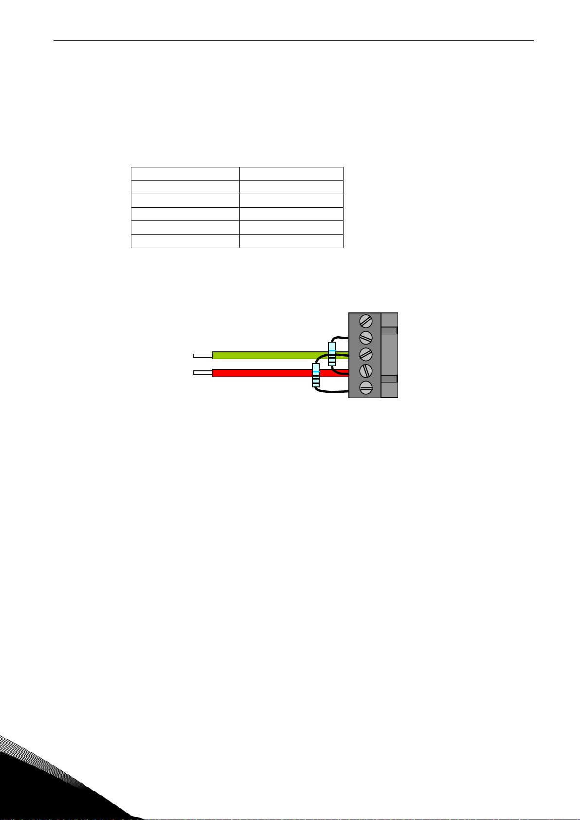
4.4 Bus Biasing
Bus biasing is required to ensure faultless communication between devices at RS-485 bus. Bus
biasing makes sure that the bus state is at proper potential when no device is transmitting. Without
biasing, faulty messages can be detected when the bus is in idle state. RS-485 bus state should be
neather +0,200..+7V or –0,200..-7V. Illegal bus state is <200mV..-200mV.
Number of nodes Bias resistance
2-5 1.8 kohm
5-10 2.7 kohm
11-20 12 kohm
21-30 18 kohm
Table 4-1. Bias resistor size vs number of node
Fail safe
biasing in OPT-CJ option board
Connect resistor biasing resistors between pins #2 and #4 as well as pins #3 and #5 as shown in
picture.
Matters related to this are discussed in the application note
Failsafe Biasing of Differential Buses
(an-847.pdf) published by National Semiconductor (www.national.com).
4
5
Tel. +358 (0)201 2121 • Fax +358 (0)201 212 205
 Loading...