

Page 1

vacon® nxn
ac drives
non-regenerative front end unit (nfe)
user manual
Page 2

AT LEAST THE 11 FOLLOWING STEPS OF THE
START-UP QUICK GUIDE
MUST BE PERFORMED DUR-
ING THE INSTALLATION AND COMMISSIONING.
IF ANY PROBLEMS OCCUR, PLEASE CONTACT YOUR LOCAL DISTRIBUTOR.
Start-up Quick Guide
1. Check that the delivery corresponds to your order, see Chapter 3
2. Before taking any commissioning actions, read carefully the safety instructions
in Chapter 1.2
3. Before the mechanical installation, check the minimum clearances around the
unit and check the ambient conditions in Chapter 5
4. Check the size of the supply cable/bus bar, DC output cable/bus bar, and mains
fuses, DC fuses and check the cable connections.
5. Follow the installation instructions, see Chapter 5.
6. The sizes and grounding of control connections are explained in Chapter 5.
7. All parameters have factory default values. No any changes need to make for
proper operation.
8. The VACON
®
NX Non-Regenerative Front End is now ready for use.
Vacon Ltd is not responsible for the use of the Non-Regenerative Front End against
the instructions.
Page 3

vacon 2
Local contacts: https://www.danfoss.com/en/contact-us/contacts-list/
CONTENTS
VACON® NXN USER MANUAL
INDEX
1 SAFETY
2 EU DIRECTIVE
3 RECEIPT OF DELIVERY
4 Non-REGENERATIVE FRONT END UNIT (NFE)
5 INSTALLATION
6 CONTROL KEYPAD
7 APPENDICES
Page 4

vacon 3
Local contacts: https://www.danfoss.com/en/contact-us/contacts-list/
1
ABOUT THE VACON® NXN USER'S MANUAL
Congratulations for choosing VACON® NX Non-Regenerative Front End!
The User's Manual will provide you with the necessary information about the installation, commissioning
and operation of VACON® NX Non-Regenerative Front End. We recommend that you carefully study these
instructions before powering up the Non-Regenerative Front End for the first time.
In the Non-Regenerative Front End Application Manual you will find information about the Nonregenerative Front End application. Should that application not meet the requirements of your process,
please contact the manufacturer for information on special application.
This manual is available in both paper and electronic editions. We recommend you to use the electronic
version if possible. If you have the electronic version at your disposal, you will be able to benefit from the
following features:
The manual contains several links and cross-references to other locations in the manual, which makes it
easier to move around in the manual. The reader can thus easily find and check things.
The manual also contains hyperlinks to web pages. To visit these web pages through the links, you must
have an internet browser installed on your computer.
This manual is applicable only for Non-Regenerative Front End unit, AC choke and optional components
that are introduced in this manual.
Page 5

vacon 4
Local contacts: https://www.danfoss.com/en/contact-us/contacts-list/
VACON® NX N User Manual
Table of contents
Document code: DPD01172C
Date edited: 30.01.2019
1. Safety ............................................................................................................................ 6
1.1 Warnings ........................................................................................................................................ 6
1.2 Safety Instructions ........................................................................................................................ 6
1.3 Grounding ...................................................................................................................................... 6
1.4 Warning symbols ........................................................................................................................... 7
2. EU directive ................................................................................................................... 8
2.1 CE marking .................................................................................................................................... 8
2.2 EMC directive ................................................................................................................................. 8
2.2.1 Introduction........................................................................................................................... 8
2.2.2 Technical criteria .................................................................................................................. 8
2.2.3 VACON® Non-Regenerative Front End EMC classification ............................................... 8
2.2.4 .......................................................................... 8
3. Receipt of delivery ................................ ....................................................................... 10
3.1 Type designation code for the NFE unit ..................................................................................... 10
3.2 Type designation code for the AC choke .................................................................................... 12
3.3 Storage ......................................................................................................................................... 12
3.4 Maintenance ................................................................................................................................ 12
3.5 Lifting the modules ..................................................................................................................... 13
3.6 Lifting the AC choke .................................................................................................................... 14
3.7 Warranty ...................................................................................................................................... 14
4. Non-Regenerative Front End (NFE) .............................................................................. 15
4.1 Introduction ................................................................................................................................. 15
4.2 Non-Regenerative Front End enclosure sizes .......................................................................... 17
4.3 Non-Regenerative Front End unit technical data ..................................................................... 18
4.4 Application ................................................................................................................................... 19
4.5 Diagrams...................................................................................................................................... 19
4.5.1 Connection between control unit and power unit ............................................................ 19
4.6 Non-Regenerative Front End power ratings ............................................................................. 20
4.6.1 VACON® NXN; DC voltage 460 800V ................................................................................. 20
4.6.2 VACON® NXN; DC voltage 640 1100V ............................................................................... 20
4.7 Non-Regenerative Front End unit Dimensions ...................................................................... 20
4.8 AC choke Dimensions .............................................................................................................. 20
4.9 Non-Regenerative Front End Fuse selection ......................................................................... 21
4.9.1 Introduction......................................................................................................................... 21
4.9.2 Fuses; mains voltage 380 690V ........................................................................................ 21
4.9.2.1 AC fuses........................................................................................................................ 21
4.9.2.2 DC fuses ....................................................................................................................... 21
4.10 Non-Regenerative Front End unit Circuit breaker selection ................................................ 21
4.11 Non-Regenerative Front End unit Main contactor ................................................................. 22
4.12 Pre-Charging and start up.......................................................................................................... 22
Page 6

vacon 5
Local contacts: https://www.danfoss.com/en/contact-us/contacts-list/
1
4.13 Paralleling ................................................................................................................................... 22
4.14 12-pulse solution ......................................................................................................................... 23
4.15 Derating ....................................................................................................................................... 23
4.15.1 As the Ambient Temperature ............................................................................................ 23
4.15.2 As the Installation altitude ................................................................................................. 25
5. Installation .................................................................................................................. 27
5.1 Mounting ...................................................................................................................................... 27
5.1.1 Non-Regenerative Front End Unit..................................................................................... 27
5.1.2 AC choke ............................................................................................................................. 28
5.1.3 Control Box ......................................................................................................................... 29
5.2 Cooling ......................................................................................................................................... 29
5.2.1 Non-Regenerative Front End unit .................................................................................... 29
5.2.2 AC choke ............................................................................................................................. 31
5.2.3 Arranging ventilation of the enclosure ............................................................................. 32
5.2.4 Steering air flow ................................................................................................................. 34
5.3 Power connection ........................................................................................................................ 35
5.3.1 AC connection ..................................................................................................................... 35
5.3.2 DC connection ..................................................................................................................... 36
5.4 Cable installation and the UL standards ................................................................................... 36
5.5 I/O terminals and I/O signals ...................................................................................................... 37
6. Control keypad ............................................................................................................. 40
6.1 Navigation .................................................................................................................................... 41
6.1.1 Monitoring menu ................................................................................................................ 41
6.1.2 Parameter menu ................................................................................................................ 42
6.1.3 Fault history menu ............................................................................................................. 44
6.1.4 System menu ...................................................................................................................... 46
7. Appendices .................................................................................................................. 47
Page 7
Safety vacon 6
Local contacts: https://www.danfoss.com/en/contact-us/contacts-list/
1
1. SAFETY
1.1 Warnings
WARNING
1
The components of the power unit circuit are live when the NonRegenerative Front End is connected to AC supply. Coming into contact
with this voltage is extremely dangerous and may cause death or severe
injury. The control unit is isolated from mains potential.
2
The control I/O-terminals are isolated from the mains potential. However, the relay outputs and other I/O-terminals may have dangerous control
voltage present even when the Non-Regenerative Front End is disconnected from the AC supply.
3
Do not touch the components on the circuit boards. Static voltage discharge may damage the components.
1.2 Safety Instructions
1
The Non-Regenerative Front End, AC choke and optional components are
meant for fixed installations only.
2
Do not perform any measurements when the Non-Regenerative Front
End is connected to the AC supply.
3
After having disconnected the Non-Regenerative Front End from the AC
supply, wait until the fan stops. Wait 5 more minutes before doing any
work on the Non-Regenerative Front End connections. Do not even open
the cover before this time has expired.
4
Do not perform any voltage withstand tests on any part of the NonRegenerative Front End. There is a certain procedure according to which
the tests must be performed. Ignoring this procedure may result in damaged product.
5
Before connecting the Non-Regenerative Front End to AC supply, make
sure that the Non-Regenerative Front End front and cable covers are
closed.
6
Before doing any work on Common DC bus, system must be grounded.
1.3 Grounding
The Non-Regenerative Front End unit and AC choke must always be grounded with an grounding
conductor connected to the grounding terminal.
ONLY A COMPETENT ELECTRICIAN MAY CARRY OUT
THE ELECTRICAL INSTALLATION
!
Page 8
vacon 7 Safety
Local contacts: https://www.danfoss.com/en/contact-us/contacts-list/
1
1.4 Warning symbols
For your own safety, please pay special attention to the instructions marked with the following symbols:
=
Dangerous voltage
WARNING
=
General warning
HOT SURFACE
=
Hot surface Risk of burn
NOTE! You can download the English and French product manuals with applicable safety, warning
and caution information from https://www.danfoss.com/en/service-and-support/.
REMARQUE Vous pouvez télécharger les versions anglaise et française des manuels produit
sur le site https://www.danfoss.com/en/service-and-support/.
Page 9

EU directive vacon 8
Local contacts: https://www.danfoss.com/en/contact-us/contacts-list/
2
2. EU DIRECTIVE
2.1 CE marking
The CE marking on the product guarantees the free movement of the product within the EEA (European Economic Area). It also guarantees that the product complies with applicable directives (for
example, the EMC directive and other possible so-called new method directives). VACON® NX NonRegenerative Front End carries the CE label as a proof of compliance with the Low Voltage Directive
(LVD) and the Electro Magnetic Compatibility (EMC) directive. SGS FIMKO has acted as the Notified
Body.
2.2 EMC directive
2.2.1
Introduction
The EMC Directive provides that the electrical apparatus must not excessively disturb the environment it is used in, and, on the other hand, it must have an adequate level of immunity toward other
disturbances from the same environment.
The compliance of VACON® NX Non-Regenerative Front End with the EMC directive is verified with
Technical Construction Files (TCF) and checked and approved by SGS FIMKO, which is a Notified
Body. The Technical Construction Files are used to authenticate the conformity of VACON® NX Non-
Regenerative Front End with the Directive because it is impossible to test such a large product family in a laboratory environment and because the combinations of installation vary greatly.
2.2.2
Technical criteria
Our basic idea was to develop a range of VACON® NX Non-Regenerative Front End offering the best
possible usability and cost efficiency. EMC compliance was a major consideration from the outset of
the design.
2.2.3
VACON® Non-Regenerative Front End EMC classification
Factory delivered VACON® NX Non-Regenerative Front End are Class T equipment, which fulfills all
EMC immunity requirements (standard EN 61800-3).
Class T:
Class T equipment have a small earth leaking current and can be used with floating DC input.
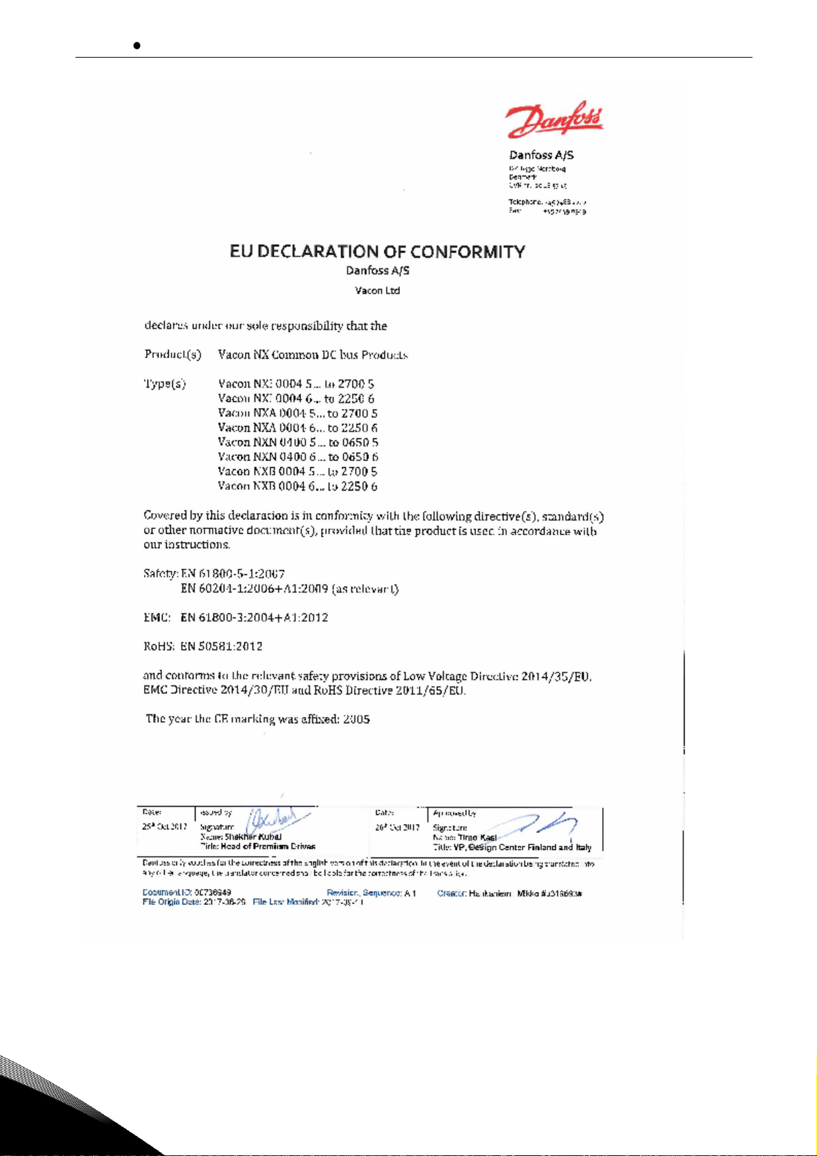
2.2.4
The following page presents the photocopy of the Manufacturer's Declaration of Conformity assuring
the compliance of VACON® NX Non-Regenerative Front End with the EMC-directives.
Warning: This product is of the restricted sales distribution class according to IEC 61800-3. In residential areas, this product may cause radio interference in which case the user may be required to
take adequate measures.
Page 10
vacon 9 EU directive
Local contacts: https://www.danfoss.com/en/contact-us/contacts-list/
2
Page 11

Receipt of delivery vacon 10
Local contacts: https://www.danfoss.com/en/contact-us/contacts-list/
3
3. RECEIPT OF DELIVERY
VACON® NX Non-Regenerative Front End has undergone scrupulous tests and quality checks at the
factory before they are delivered to the customer. However, after unpacking the product, check that
no signs of transportation damage are to be found on the product and that the delivery is complete
(compare the type designation of the product to the codes below, see Figure 3-1 and Figure 3-2).
Should the product have been damaged during the shipping, please contact primarily the cargo insurance company or the carrier.
If the delivery does not correspond to your order, contact the supplier immediately.
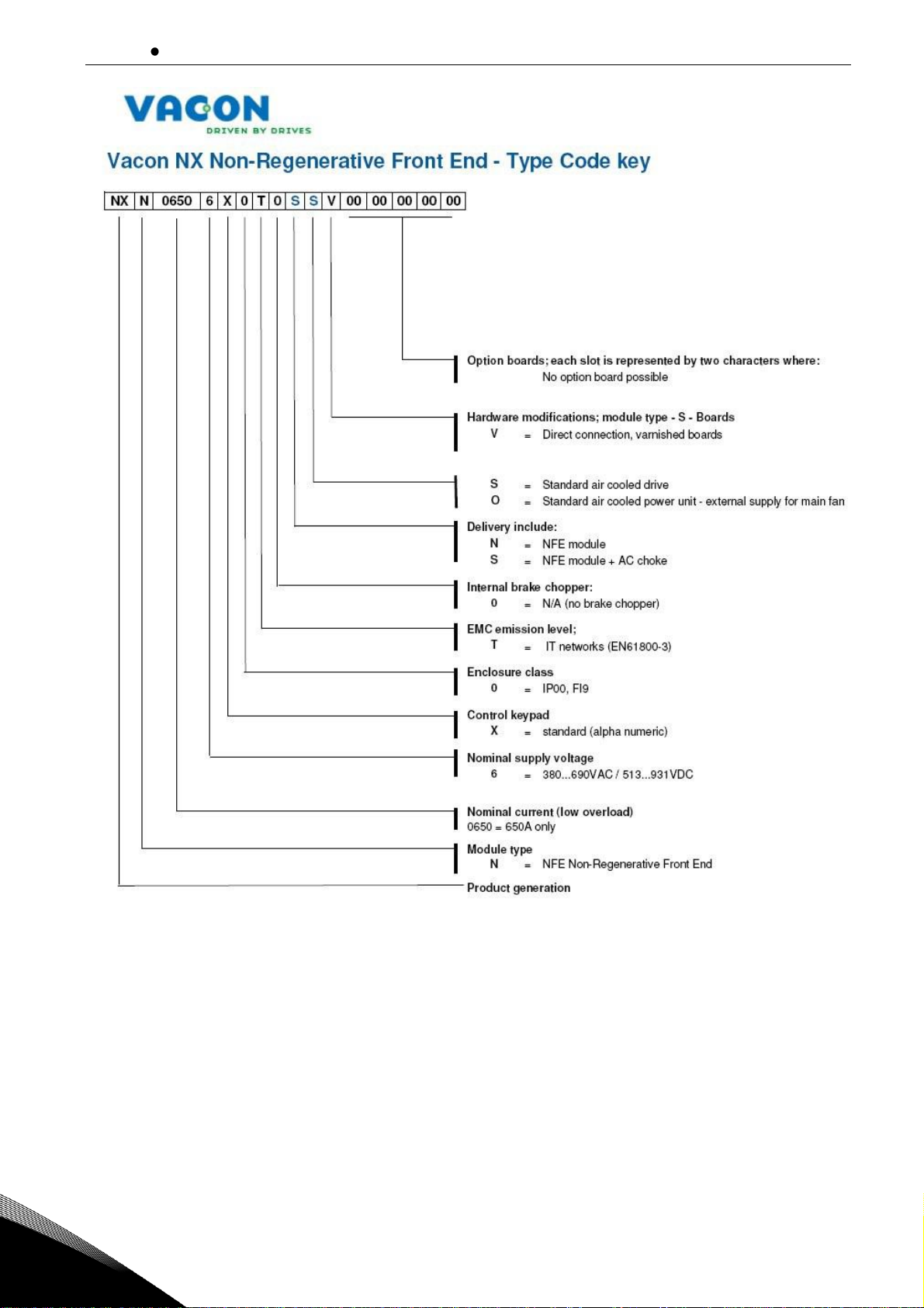
3.1 Type designation code for the NFE unit
In VACON® type designation code for Common DC Bus components, the Non-Regenerative Front End
Unit is characterized by letter N and letter N or S. If the Non-Regenerative Front End unit is ordered
by letter N delivery is not include anything else than the unit itself. If letter S is used delivery include
the unit, the AC choke.
NOTE! Delivery does NOT include any auxiliary devices which are needed for proper operation (the
AC or DC fuses, the fuses bases, the main contactor or circuit breaker etc.) The customer must take
care of them.
Page 12
vacon 11 Receipt of delivery
Local contacts: https://www.danfoss.com/en/contact-us/contacts-list/
3
Figure 3-1. Type designation code for the Non-Regenerative Front End.
Page 13
Receipt of delivery vacon 12
Local contacts: https://www.danfoss.com/en/contact-us/contacts-list/
3
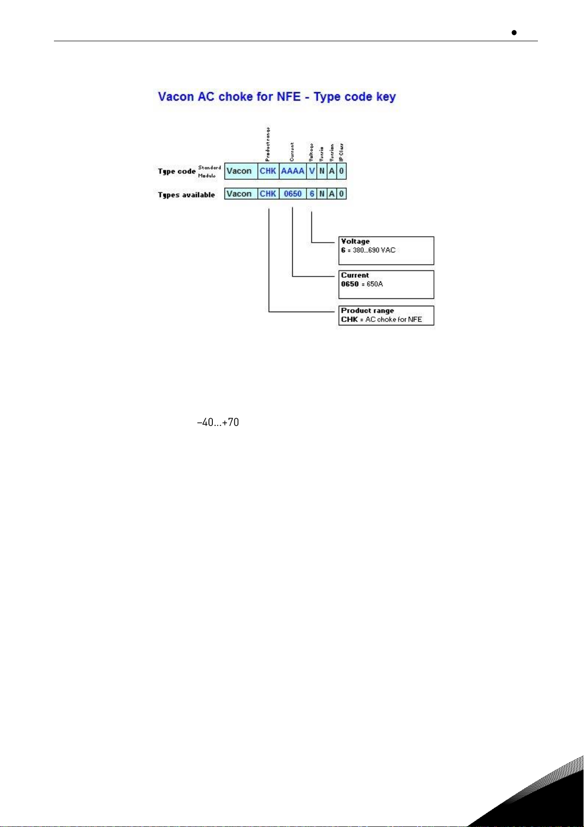
3.2 Type designation code for the AC choke
AC choke has one version which is suitable for 380-500V and 525-690V voltages.
Figure 3-2. Type designation code for the AC choke.
3.3 Storage
If VACON® NX Non-Regenerative Front End is to be stored before use, make sure that the ambient
conditions are acceptable:
Storage temperature °C
Relative humidity <95%, no condensation
3.4 Maintenance
All technical devices, drives as well, need a certain amount of care-taking and failure preventive
maintenance. To maintain trouble-free operation of the VACON® NX Non-Regenerative Front End,
environmental conditions, as well as load, line power, process control, etc. have to be within specifications, determined by manufacturer.
If all conditions are in accordance with the manufacturer's specifications, there are no other concerns, but to provide a cooling capacity high enough for the power- and control circuits. This requirement can be met by making sure, that the cooling system works properly. Operation of cooling
fans and cleanness of the heat sink should be verified regularly.
Regular maintenance is recommended to ensure trouble free operation and long lifetime of VACON®
NX Non-Regenerative Front End. At least the following things should be included in the regular
maintenance.
Page 14
vacon 13 Receipt of delivery
Local contacts: https://www.danfoss.com/en/contact-us/contacts-list/
3
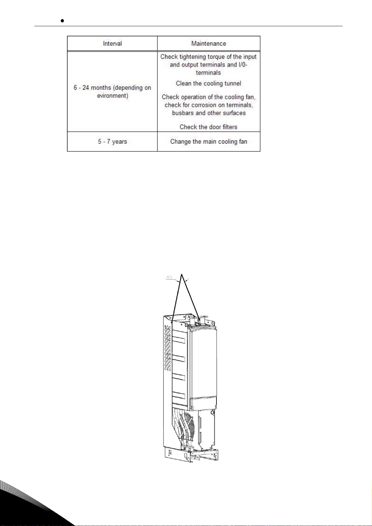
Table 3-1. Maintenance interval
It may also be necessary to check the tightening torques of terminals at certain intervals.
It is also recommended to record all actions and counter values with dates and time for follow up of
maintenance. It may also be necessary to check the tightening torques of terminals at certain intervals.
3.5 Lifting the modules
The modules can be lifted by the holes on top. Place the lifting hooks symmetrically in at least four
holes. The maximum allowed lifting angle is 45 degrees. For enclosures FI9, see Figure 3-3.
The lifting equipment must be able to carry the weight of the module.
Figure 3-3. Lifting points for FI9 module.
Page 15
Receipt of delivery vacon 14
Local contacts: https://www.danfoss.com/en/contact-us/contacts-list/
3
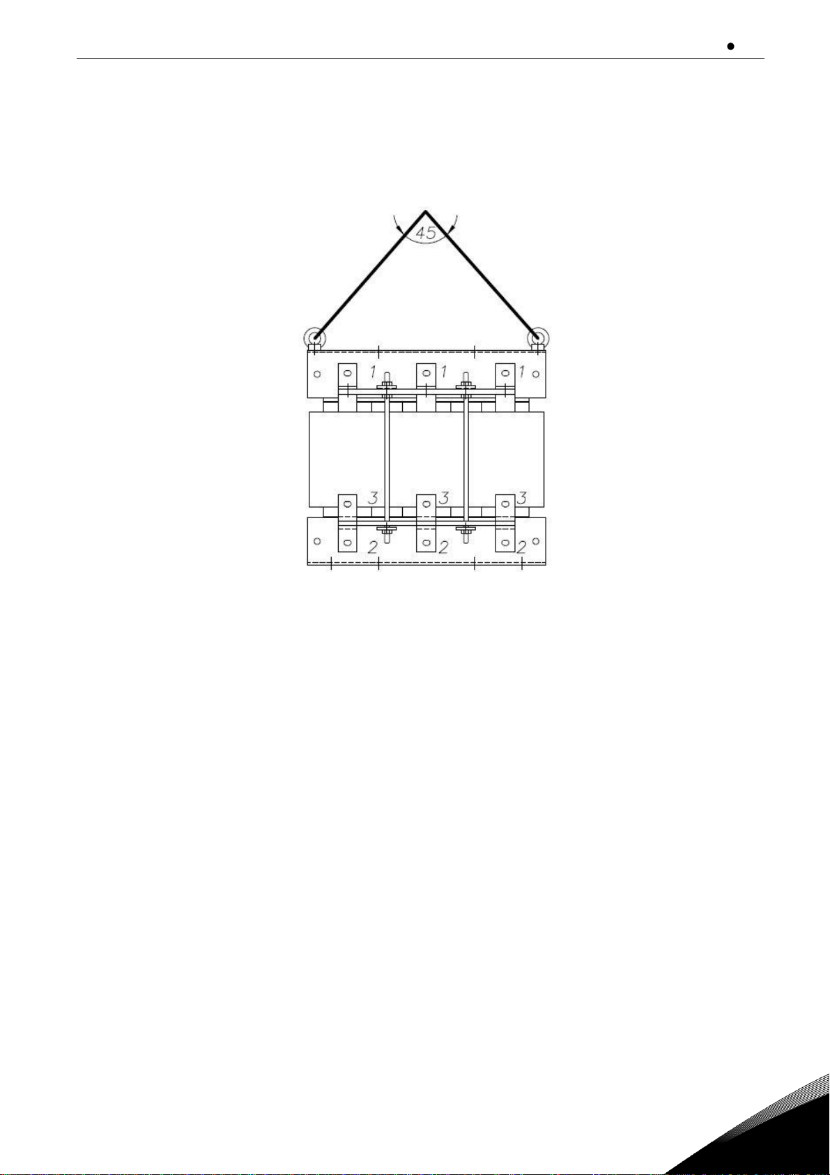
3.6 Lifting the AC choke
The AC choke can be lifted by the holes on top. Place the lifting hooks symmetrically in two holes.
The maximum allowed lifting angle is 45 degrees. Lifting points for the AC choke, see Figure 3-4.
Figure 3-4. Lifting points for AC choke.
3.7 Warranty
Only manufacturing defects are covered by the warranty. The manufacturer assumes no responsibility for damages caused during or resulting from transport, receipt of the delivery, installation, commissioning or use.
The manufacturer shall in no event and under no circumstances be held responsible for damages
and failures resulting from misuse, wrong installation, unacceptable ambient temperature, dust,
corrosive substances or operation outside the rated specifications.
Neither can the manufacturer be held responsible for consequential damages.
The Manufacturer's warranty period is 18 months from the delivery or 12 months from the commis-
sioning whichever expires first (General delivery terms NL92/Orgalime S92).
The local distributor may grant a warranty time different from the above. This warranty time shall be
specified in the distributor's sales and warranty terms. The manufacturer assumes no responsibility
for any other warranties than that granted by the manufacturer itself.
In all matters concerning the warranty, please contact your distributor first.
Page 16
vacon 15 Non-Regenerative Front End (NFE)
Local contacts: https://www.danfoss.com/en/contact-us/contacts-list/
4
4. NON-REGENERATIVE FRONT END (NFE)
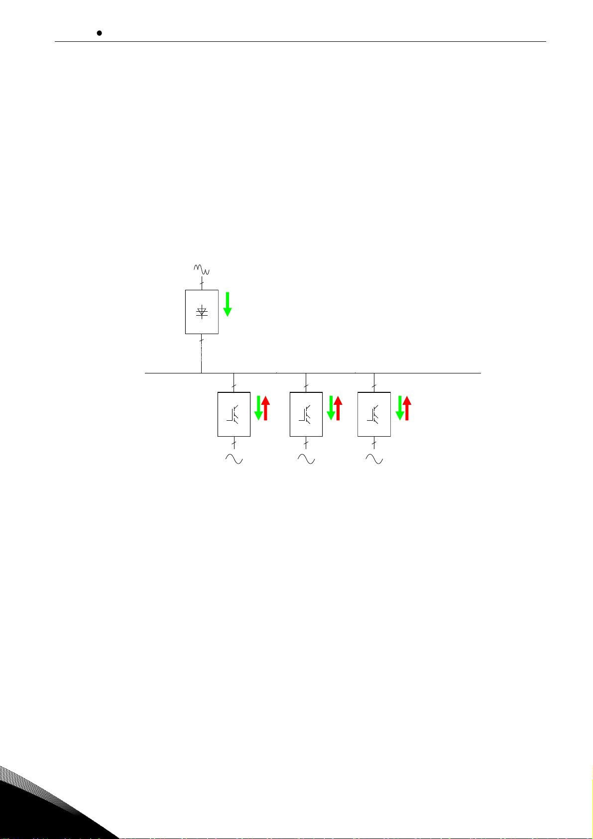
4.1 Introduction
The VACON® NX Non-Regenerative Front End is used to transfer power between the AC input and
intermediate DC circuit. The VACON® NX Non-Regenerative Front End has only a one-way function.
This means that power can only be transferred from the AC input to the intermediate DC circuit. If
braking is needed, brake chopper has to be connected to the intermediate DC circuit.
In a typical VACON® NX Non-Regenerative Front End configuration, the desired number of Inverters,
Figure 4-1, are connected to the intermediate DC circuit.
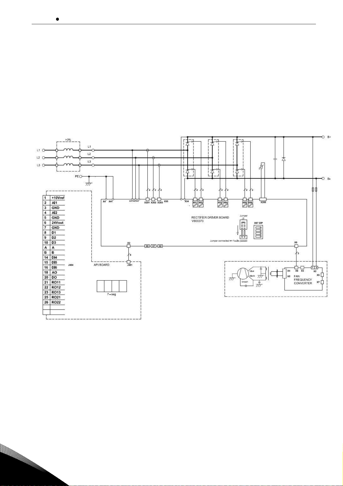
The Non-Regenerative Front End configuration consists of the unit itself, AC choke, AC fuses, main
contactor and DC fuses, Figure 4-2.
Figure 4-1. Typical Non-Regenerative Front End configuration.
NFE*
3
FFE*
3
2
3
INU
2
3
INU
2
3
INU
2
2
BCU
AFE*
Common DC bus
* alternative
2 2 2
Page 17

Non-Regenerative Front End (NFE) vacon 16
Local contacts: https://www.danfoss.com/en/contact-us/contacts-list/
4
Figure 4-2. VACON® Non-Regenerative Front End Single Unit connections
CLOSE
-RO2
26
24
25
Page 18

vacon 17 Non-Regenerative Front End (NFE)
Local contacts: https://www.danfoss.com/en/contact-us/contacts-list/
4
4.2 Non-Regenerative Front End enclosure sizes
Figure 4-3. VACON® NXN, FI9. Protection class IP00
Page 19

Non-Regenerative Front End (NFE) vacon 18
Local contacts: https://www.danfoss.com/en/contact-us/contacts-list/
4
4.3 Non-Regenerative Front End unit technical data
Mains connection
Input voltage Uin
380 - 690 Vac; -15%...+10%, EN 60204-1
Input frequency
45…66 Hz
Continuous input current
IH: Ambient temperature max. +40°C,
overload 1.5 x IH (1 min./10 min.)
IL: Ambient temperature max. +40°C,
overload 1.1 x IL (1 min./10 min.)
Connection to mains
Unlimited (internal overload protections)
Current THD
Depend on additional chokes ( normal case < 40%)
Starting delay
Depend on dc bus capacitance (max 10 s)
Unexpected input power
break
Shorter breaks than 40ms works normally if DC does not drop
remarkably. Longer break means normal starting operation
(charging current varies according to load).
DC
connection
Output voltage Uout
465...800Vdc ( 380-500 Vac);
640...1100Vdc ( 525-690 Vac);
Efficiency
>98%
DC bank capasitance
6.8µF (included 10 M discharging resistor)
Control characteristics
Control method
NFE is an independent power unit. Charging and protections
controlled by NFE itself.
Ambient conditions
Ambient operating temperature
H
L
Storage temperature
–40°C…+70°C
Relative humidity
0 to 95% RH, non-condensing, non-corrosive,
no dripping water
Air quality:
- chemical vapours
- mechanical particles
IEC 721-3-3, unit in operation, class 3C2
IEC 721-3-3, unit in operation, class 3S2
Altitude
100% load capacity (no derating) up to 1,000 m
1-% derating for each 100m above 1000.; max. 2000m
Vibration
EN50178/EN60068-2-6
Displacement amplitude 0.
Shock
EN50178, EN60068-2-27
UPS Drop Test (for applicable UPS weights)
Storage and shipping: max 15 G, 11 ms (in package)
Cooling air required
1150 m3/h
Enclosure class
IP00/Open type standard size in the kW/HP range
EMC
(at default settings)
Immunity
Fulfil all EMC immunity requirements. Can be chosen N-, L- or
T-level.
Safety
CE, UL, CUL
EN 61800-5-1 (2003); (see unit nameplate for more detailed
approvals)
Control connections
Display
LCD
Trip information
Relay I/O
Auxiliary voltage
+24 V, +/- 20%, max. load 50 mA
Analogue output
0(4)-20 mA, RL=500 Ohm
Digital output
Open collector, max. Load 48V/50 mA
Relay outputs
Max switching load: 250Vac/2A or 250Vdc/0.4 A
Protections
Unit over temperature protection
Trips if temperature rising over trip level (default)
Current measurement
Trips if current over trip level (default)
Supply phase supervision
Trips if any of the output phases is missing (default)
Table 4-1. Technical specification for VACON® NX Non-Regenerative Front End unit
Page 20
vacon 19 Non-Regenerative Front End (NFE)
Local contacts: https://www.danfoss.com/en/contact-us/contacts-list/
4
4.4 Application
The VACON® NX Non-Regenerative Front End needs a special application. The unit is delivered with
that application. If application code is needed please contact please contact the manufacturer. More
information about application can be found from this manual.
4.5 Diagrams
4.5.1
Connection between control unit and power unit
The communication connections between the Non-Regenerative Front End power unit and the
con-
trol unit
is established using serial cable, Figure 4-4. The control unit is located under the front cov-
er of the power unit. The control unit cannot place outside of the power unit.
Figure 4-4. NFE power and control connections.
Page 21
Non-Regenerative Front End (NFE) vacon 20
Local contacts: https://www.danfoss.com/en/contact-us/contacts-list/
4
4.6 Non-Regenerative Front End power ratings
4.6.1
VACON® NX N; DC voltage 460 800V
Unit
Low oveload
(AC current)
High oveload
(AC current)
DC Power
(continuous)
Type
Code
Enclosure
I
L-cont [A]
I
1min [A]
I
H-cont [A]
I
1min [A]
400V mains
500 V mains
P [kW]
P [kW]
NFE
NXN_0650 6
FI9
650
715
507
793
410
513
Table 4-2. Power ratings of VACON® NXN, supply voltage 460 800Vdc
For dimensions of NXN units, see Table 4-4 and AC choke Table 4-5.
Note: The rated currents in given ambient (+40°C).
Note: The motor output power: Pout=Pdc x (Eff.INU x Eff.Motor).
Pdc =NFEs DC power
Eff.INU=efficiency of the inverter
Eff.Motor=efficiency of the motor
4.6.2
VACON® NX N; DC voltage 640 1100V
Unit
Low oveload
(AC current)
High oveload
(AC current)
DC Power
(continuous)
Type
Code
Enclosure
I
L-cont [A]
I
1min [A]
I
H-cont [A]
I
1min [A]
690V mains
P [kW]
NFE
NXN_0650 6
FI9
650
715
507
793
708
Table 4-3. Power ratings of VACON® NXN, supply voltage 640 1100Vdc
For dimensions of NXN unit, see Table 4-4 and AC choke Table 4-5.
Note: The rated currents in given ambient (+40°C).
Note: The motor output power: Pout=Pdc x (Eff.INU x Eff.Motor).
Pdc =NFEs DC power
Eff.INU=efficiency of the inverter
Eff.Motor=efficiency of the motor
4.7 Non-Regenerative Front End unit Dimensions
Module
Module Dimension
Type
Enclosure
Height
Width
Depth
Weight
[mm]
[mm]
[mm]
[kg]
NFE
FI9
1030
239
372
67
Table 4-4. The NXN unit dimensions
Note: More detailed dimensions can be found in Appendix 7-4.
4.8 AC choke Dimensions
Module
Module Dimension
Type
Enclosure
Height
Width
Depth
Weight
[mm]
[mm]
[mm]
[kg]
AC choke
CHK-650
449
497
249
130
Table 4-5. AC choke dimensions
Note: More detailed dimensions can be found Appendix 7-5.
Page 22

vacon 21 Non-Regenerative Front End (NFE)
Local contacts: https://www.danfoss.com/en/contact-us/contacts-list/
4
4.9 Non-Regenerative Front End Fuse selection
4.9.1
Introduction
AC fuses are used to protect the input network in case the Non-Regenerative Front End unit or the
AC choke is faulty. DC fuses are used to protect the Non-Regenerative Front End unit and the AC
choke in case there is a short circuit in the DC buses. If DC fuses are not used, short-circuit in the
DC buses will cause a loading of the Non-Regenerative Front End unit. Vacon Ltd will not assume
any responsibility for damages caused by insufficient protection.
4.9.2
Fuses; mains voltage 380 690V
4.9.2.1 AC fuses
Module
AC fuses
Type
Code
Enclosure
Ferraz Shawmut
UN
[V]
IN [A]
Size
Q'ty
type [aR]*
NFE
NXN_0650 6
FI9
NH3UD69V1000PV
690
1000
3
3
Table 4-6. Ferraz Shawmut AC fuse selection, mains voltage 380 690Vac
Module
AC fuses
Type
Code
Enclosure
Bussman
UN
[V]
IN [A]
Size
Q'ty
type [aR]*
NFE
NXN_0650 6
FI9
170M6466
690
1250
3BKN/50
3
Table 4-7. Bussman AC fuse selection, mains voltage 380 690Vac
Note: All fuses are blade type. If some other type is needed please contact your nearest distributor.
4.9.2.2 DC fuses
Module
DC fuses
Type
Code
Enclosure
Ferraz Shawmut
UN
[V]
IN [A]
Size
Q'ty
type [aR]*
NFE
NXN_0650 6
FI9
PC73UD11C13CTF
1100
1250
73(LR)
2
Table 4-8. Ferraz Shawmut DC fuse selection, mains voltage 465 1100Vdc
Module
DC fuses
Type
Code
Enclosure
Bussman
UN
[V]
IN [A]
Size
Q'ty
type [aR]*
NFE
NXN_0650 6
FI9
170M8610
1000
1000
3BKN/75
2
Table 4-9. Bussman DC fuse selection, mains voltage 465 1100Vdc
Note: All fuses are flush-end type. If some other type is needed please contact your nearest distributor.
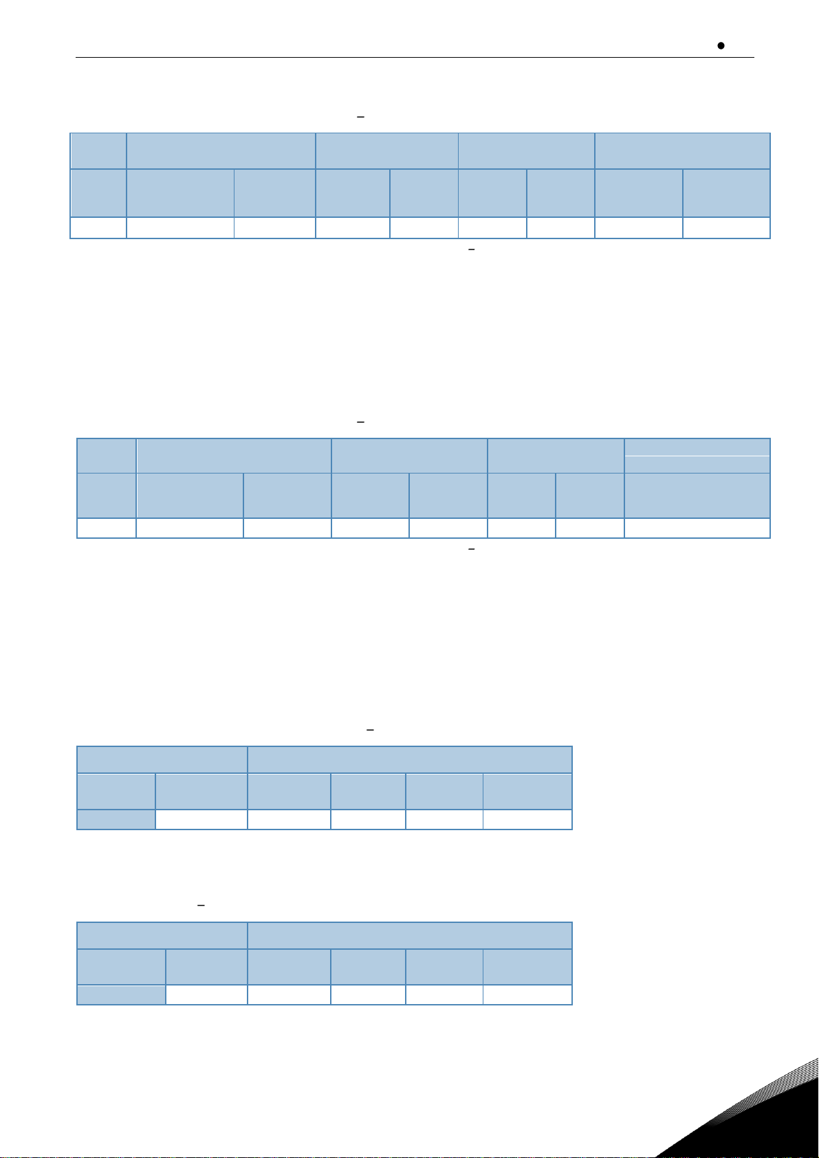
4.10 Non-Regenerative Front End unit Circuit breaker selection
The Non-Regenerative Front End can also be protected by a circuit-breaker. The recommended type
of circuit-breaker is shown in Table 4-10. If a circuit-breaker from another manufacturer is used, it
must be equivalent to the circuit-breaker shown. Further information on the circuit-breaker shown
is available from the manufacturer. Circuit-breaker does not provide the same level of protection as
Page 23
Non-Regenerative Front End (NFE) vacon 22
Local contacts: https://www.danfoss.com/en/contact-us/contacts-list/
4
fuses. A circuit-breaker can be used without a main contactor. The circuit-breakers shown are suitable for equipment rated at 380 690 V.
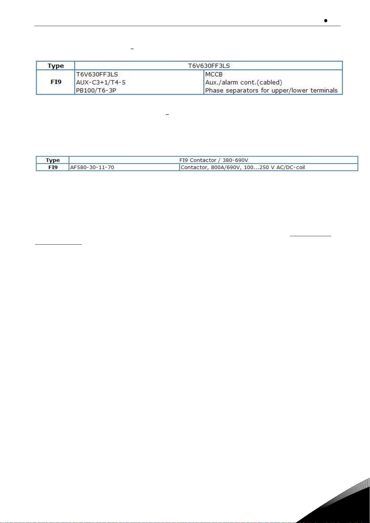
Table 4-10. Circuit breaker for VACON® NXN
4.11 Non-Regenerative Front End unit Main contactor
If a main contactor is to be used, the type shown in Table 4-11 are recommended. If a contactor from
another manufacturer is used, it must be equivalent to the types shown. Further information on the
contactor shown is available from the manufacturer.
Table 4-11. Recommended main contactor type.
4.12 Pre-Charging and start up
External pre-charging circuit is not needed with the Non-Regenerative Front End. Pre-charging is
done by controlling thyristors and the DC link voltage is charged smoothly. Pre-charging is current
limit controlled. Due to this, the charging time varies depending on DC link capacitance. The NonRegenerative Front End performs charging when the main contactor is closed and a start signal is
applied to DIN1. The NFE goes into run mode after successful charging. If Non-regenerative Front
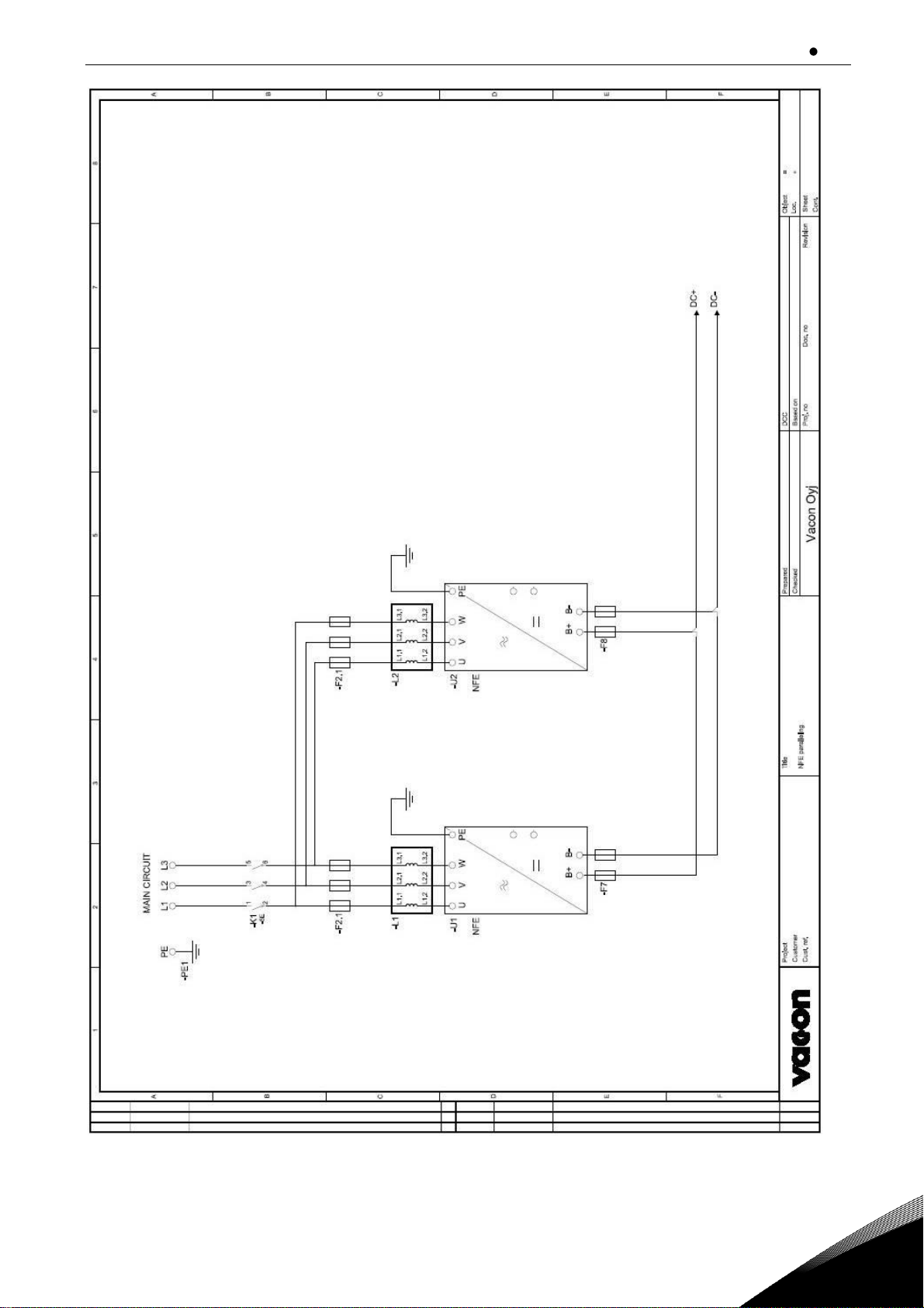
Ends are connected in parallel, each module charges DC link voltage independently. Parallel connected modules can be connected to the supply simultaneously or one module at a time. See Appendix 7-2 for the circuit diagram of parallel connected NFE modules.
The Non-Regenerative Front End monitors the pre-charging process. If the time of charging is over
the adjustable pre-charging monitoring time (default 10s) a fault is indicated. If the DC link capacitance is so high that the default value for charging monitoring is not enough, the value can be increased.
4.13 Paralleling
The power of the input group can be increased by connecting several Non-Regenerative Front End
units in parallel. No communication between the units is required; they work independently.
Each Non-Regenerative Front End unit connected in parallel must have its own short-circuit protection on AC and DC sides. The fuses are selected in accordance with Section 4.9. When paralleling,
attention must be paid to the sufficient short-circuit capacity of the system.
The derating of Non-Regenerative Front End units connected in parallel is 5% of the DC power; this
should be taken into account when selecting the input unit.
If a device is to be isolated from the AC and DC voltages, and other Non-Regenerative Front End
units connected in parallel are also to be used, separate isolators are required in the AC input and
DC output. The AC input can be isolated using a compact circuit-breaker, an ordinary circuit-breaker
or a fuse switch. Contactors are not suitable for isolating the AC input because they cannot be locked
in the safe position. The DC output can be isolated using a fuse switch. A load isolation switch or
safety isolation switch can be used for this. The device can also be connected to mains even when
the other devices connected in parallel are already connected and running. After this, the device can
be connected to the intermediate circuit.
Page 24

vacon 23 Non-Regenerative Front End (NFE)
Local contacts: https://www.danfoss.com/en/contact-us/contacts-list/
4
Note: Parallel connection means that the AC supply of more than one units connected together from DC link is
coupled with the same supply transformer.
4.14 12-pulse solution
In 12-pulse solution the supply transformer has two galvanically separated secondary circuits, see
Appendix 7-3. The 12-pulse solution can reduce the effect of harmonic waves of the current in the
supply network. In order to reduce the effect of harmonics, there must be a phase displacement of
30º between the secondary circuits of the transformer. The phase displacement is implemented by
connecting one secondary circuit to triangle and the other to star. In 12-pulse solution there must be
an equal number of non-regenerative units connected to the both secondary coils of the supply
transformer.
4.15 Derating
The output power has to be derated if one of following cases:
• Ambient temperature is more than 40ºC
• Installation altitude is more than 1000 m
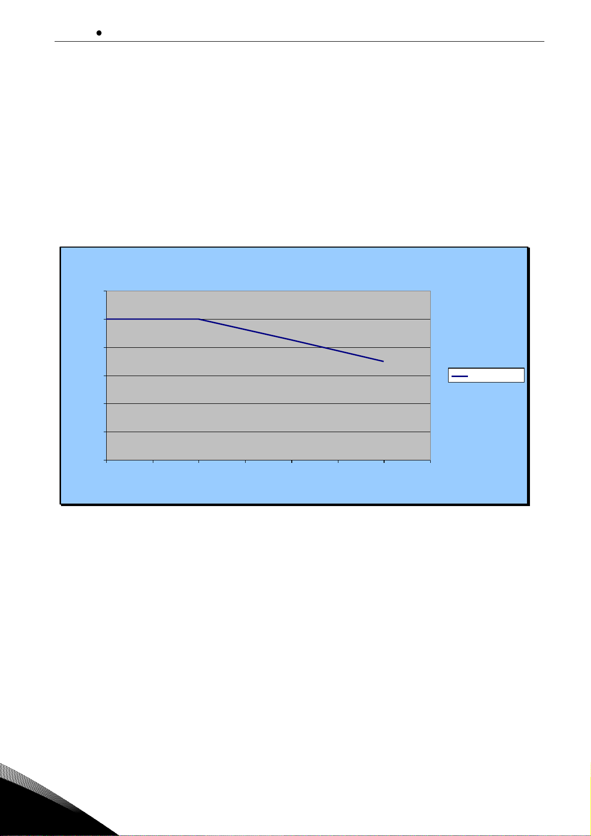
4.15.1 As the Ambient Temperature
The power rating of the Non-Regenerative Front End unit is valid for an ambient temperature of
40ºC. If the device is to be used in higher ambient temperatures, its power rating must be subjected
to derating. The derating coefficient is 1.5%/1ºC, for ambient temperatures not exceeding 50ºC. The
reduced power is calculated using the formula:
x)/100)*C)º40(%100((* −−= tPP
nde
Pn = nominal power of the unit
t = ambient temperature
x = derating coefficient
Page 25

Non-Regenerative Front End (NFE) vacon 24
Local contacts: https://www.danfoss.com/en/contact-us/contacts-list/
4
Derating as a function of ambient temperature
50
60
70
80
90
100
110
0 10 20 30 40 50 60
Ambient temperature, ºC
Loadability, %
Loadability %
Figure 4-5. Derating as the ambient temperature.
Page 26
vacon 25 Non-Regenerative Front End (NFE)
Local contacts: https://www.danfoss.com/en/contact-us/contacts-list/
4
4.15.2 As the Installation altitude
The power rating of the Non-Regenerative Front End unit is valid for a maximum installation altitude
of 1,000 m (380-690 V). If the device is to be used in higher installation altitudes, its power rating
must be subjected to derating. The derating coefficient is 1.5%/100m. The power rating of the device
can be reduced to a maximum installation altitude of 3,000 m (380V-500V) or of 2000 m (525V-690V).
The reduced power is calculated using the formula:
x)/100)*)(%100((*
baseinstnde
hhPP −−=
Pn = nominal power of the unit
hinst = intended installation altitude
hbase = 1,000 m
x = derating coefficient
Derating as a function of installation altitude
0
20
40
60
80
100
120
0 500 1000 1500 2000 2500 3000 3500
Installation altitude, m
Loadability, %
Loadability %
Figure 4-6. Derating as the installation altitude 380-500V.
Page 27

Non-Regenerative Front End (NFE) vacon 26
Local contacts: https://www.danfoss.com/en/contact-us/contacts-list/
4
Derating as a function of installation altitude
84
86
88
90
92
94
96
98
100
102
0 500 1000 1500 2000 2500
Installation altitude, m
Loadability, %
Loadability %
Figure 4-7. Derating as the installation altitude 525-690V.
Note: If higher installation altitude than 3,000 m is required please contacts your nearest distributor to get
more information.
Page 28
vacon 27 Installation
Local contacts: https://www.danfoss.com/en/contact-us/contacts-list/
5
5. INSTALLATION
5.1 Mounting
The equipment mounting must be sturdy enough to carry the weight of the equipment. The enclosure class of the equipment will depend on the mounting and solutions to be used. The equipment
mounting must provide sufficient shielding for contact of the live parts (IP2x). The installation and
mounting must comply with local laws and regulations.
5.1.1
Non-Regenerative Front End Unit
The Non-Regenerative Front End can be mounted in a vertical position on the back plane of a cubicle. Enough space must be reserved around the Non-Regenerative Front End to ensure sufficient
cooling, see Figure 5-5. Follow the minimum dimensions for installation, see Table 5-1. Required
cooling air capacity and minimum air holes on the switchgear, see Table 5-2. Also make sure that
the mounting plane is relatively even. The Non-Regenerative Front End is fixed with four bolts, Figure 5-1.
Figure 5-1. Mounting points of FI9 NFE unit.
Page 29

Installation vacon 28
Local contacts: https://www.danfoss.com/en/contact-us/contacts-list/
5
5.1.2
AC choke
The AC choke can only be mounted in a vertical position on the floor of a cubicle. Enough space must
be reserved around the AC choke to ensure sufficient cooling, see Figure 5-7. Follow the minimum
dimensions for installation, see Table 5-3. Required cooling air capacity and minimum air holes on
the switchgear, see Table 5-4. Also make sure that the floor is relatively even. AC choke must be attached properly so that it will not be able to move.
AC choke can be mounted so that the connectors face forward or so that they face to the side. Figure
5-2 presents a mounting where the connectors face forward. Figure 5-3 presents a mounting where
the connectors face to the side. This mounting is recommended if the Non-Regenerative Front End
units are parallel connected. In this case it must be assured that the connectors face to the same
direction and that there is enough space between the connectors and the AC choke.
Figure 5-2. Mounting of AC choke.
Figure 5-3. Mounting of parallel connected AC chokes.
Page 30
vacon 29 Installation
Local contacts: https://www.danfoss.com/en/contact-us/contacts-list/
5
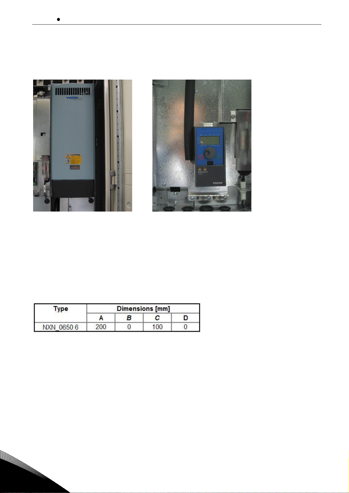
5.1.3
Control Box
The Control unit of the Non-Regenerative Front End unit is mounted under the front cover of module, see Figure 5-4. VACON® alphanumeric display and the navigation wheel can be used for parameterization and monitoring of the Non-Regenerative Front End unit.
Figure 5-4. Mounting of the control unit.
5.2 Cooling
5.2.1
Non-Regenerative Front End unit
Enough free space must be left around the Non-Regenerative Front End unit to ensure sufficient air
circulation and cooling. You will find the required dimensions for free space in the table below. You
will find the required cooling air, minimum air holes and heat dissipation in the Table 5-2.
When planning the cooling for the space, take into consideration that the Non-Regenerative Front
End unit heat loss is approx. 1% of the nominal capacity. Air flow, see Figure 5-6.
Table 5-1. Mounting space dimensions.
A = free space above the unit
B
= distance between inverter and cabinet wall
C = free space underneath of the units
D
= distance between two units
Page 31

Installation vacon 30
Local contacts: https://www.danfoss.com/en/contact-us/contacts-list/
5
Figure 5-5. Installation space for FI9.
Figure 5-6. Cooling airflow for FI9 NFE unit.
Type
Heat dissi-
pation (W)
Cooling air required
(m3/h)
Minimum air holes on
switchgear (mm2)
NXN_0650 6
2450
1150
65000
Table 5-2. Required cooling air for the Non-Regenerative Front End unit.
Page 32

vacon 31 Installation
Local contacts: https://www.danfoss.com/en/contact-us/contacts-list/
5
5.2.2
AC choke
Enough free space must be left around the AC choke to ensure sufficient air circulation and cooling.
You will find the required dimensions for free space in the table below. You will find the required
cooling air, minimum air holes and heat dissipation in the Table 5-4.
When planning the cooling for the space, take into consideration that the AC choke heat loss is approx. 0.5% of the nominal capacity.
Table 5-3. Mounting space dimensions.
A = free space above the AC choke
B
= distance between AC choke and cabinet wall
C
= free space under the AC choke
D
= distance between AC choke and cabinet wall
E
= distance between AC choke and cabinet wall
Figure 5-7. Installation space.
Type
Heat dissi-
pation
(W)
Minimum air holes on
switchgear (mm2)
CHK-0650-6
890
30000
Table 5-4. Required cooling air for the AC choke.
Page 33

Installation vacon 32
Local contacts: https://www.danfoss.com/en/contact-us/contacts-list/
5
5.2.3
Arranging ventilation of the enclosure
The enclosure door must be provided with air gaps for air intake. To achieve sufficient cooling inside
the cabinet, the dimensions for the total area of free openings for incoming air given in Table 5-2 and
Table 5-4 must be followed. For instance, there could be two screened gaps as presented in Figure
5-8 ( s recommendation). This layout ensures a sufficient air flow to the module fans
as well as cooling of the additional components.
Air outlet gaps must be situated on top of the cabinet. The minimum effective air outlet area per unit
frame is given in Table 5-2 and Table 5-4. The cooling arrangements inside the cabinet must be such
that they prevent hot output air from mixing with the incoming fresh air (see Chapter 5.2.4).
The ventilation gaps must fulfill the requirements set by the selected IP class. The examples in this
manual apply to protection class IP21.
During operation, air is sucked in and circulated by a fan blower at the bottom of the power unit. If
the power unit is placed in the upper part of the cabinet, the fan blower will be in the mid of the cabinet, at the height of the upper ventilation grid. In case of the AC choke is installed below the NonRegenerative Front End unit air inlet 1.1 in Figure 5-8 cannot be used.
Page 34

vacon 33 Installation
Local contacts: https://www.danfoss.com/en/contact-us/contacts-list/
5
Figure 5-8. Cabinet openings for cooling.
1. Cooling air inlets
2. Hot air exhaust
1.1
2
2
1.2
Page 35
Installation vacon 34
Local contacts: https://www.danfoss.com/en/contact-us/contacts-list/
5
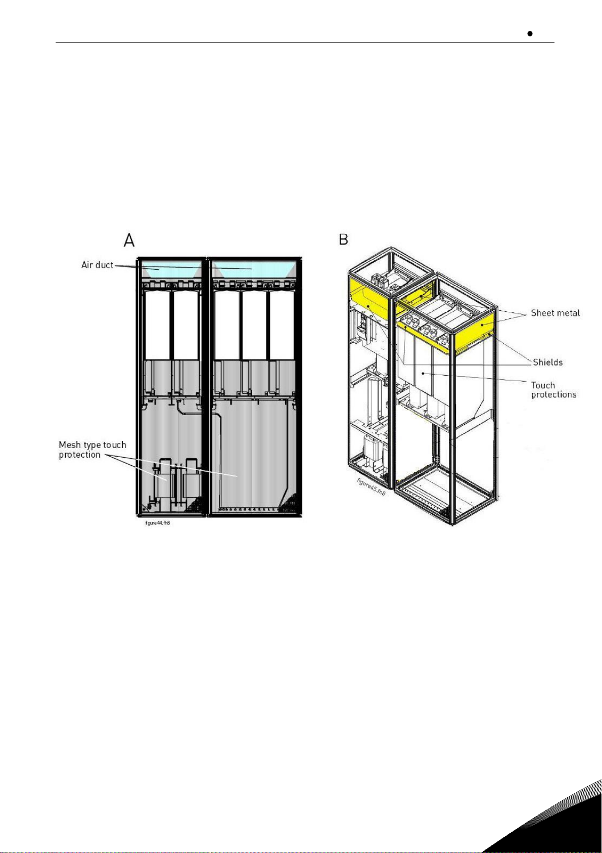
5.2.4
Steering air flow
Cooling air must be taken in through the ventilation gaps on the door and blown out at the top of the
enclosure. To steer the hot air from the power unit to the outlet at the top of the enclosure and prevent it from circulating back to the fan blower, use either of the following arrangements:
A. Install a closed air duct from the power unit to the outlet on top of the enclosure (A in
figures below).
B. Install shields in the gaps between the power unit and the cabinet walls (B in figures
below). Place the shields above the air outlet gaps at the sides of the module.
Figure 5-9. Cabinet cooling airflow guides.
The sheet metal airflow guides (deflectors) prevents air circulation between different sections of the
equipment. The shield guides in prevent air circulation inside a section. The exhaust air holes must not
be covered, nor must anything be placed above them to stop the free exit of warm air from inside the
equipment. The cooling air intake holes must not be blocked in any way.
The materials used for preventing the circulation of air inside the equipment must be fire-restraining.
The edges must be sealed to prevent the formation of gaps. When the deflectors are made according to
the instructions, no separate cooling fan is required.
NOTE! The deflectors must be installed above the air intake holes on the top (in the front) of the unit.
NOTE! If a flat roof is used, mount a V-shaped air guide on the underside of the roof to direct the air
flow horizontally. See Figure 5-10.
Page 36
vacon 35 Installation
Local contacts: https://www.danfoss.com/en/contact-us/contacts-list/
5
Figure 5-10. Roof structure seen from the side
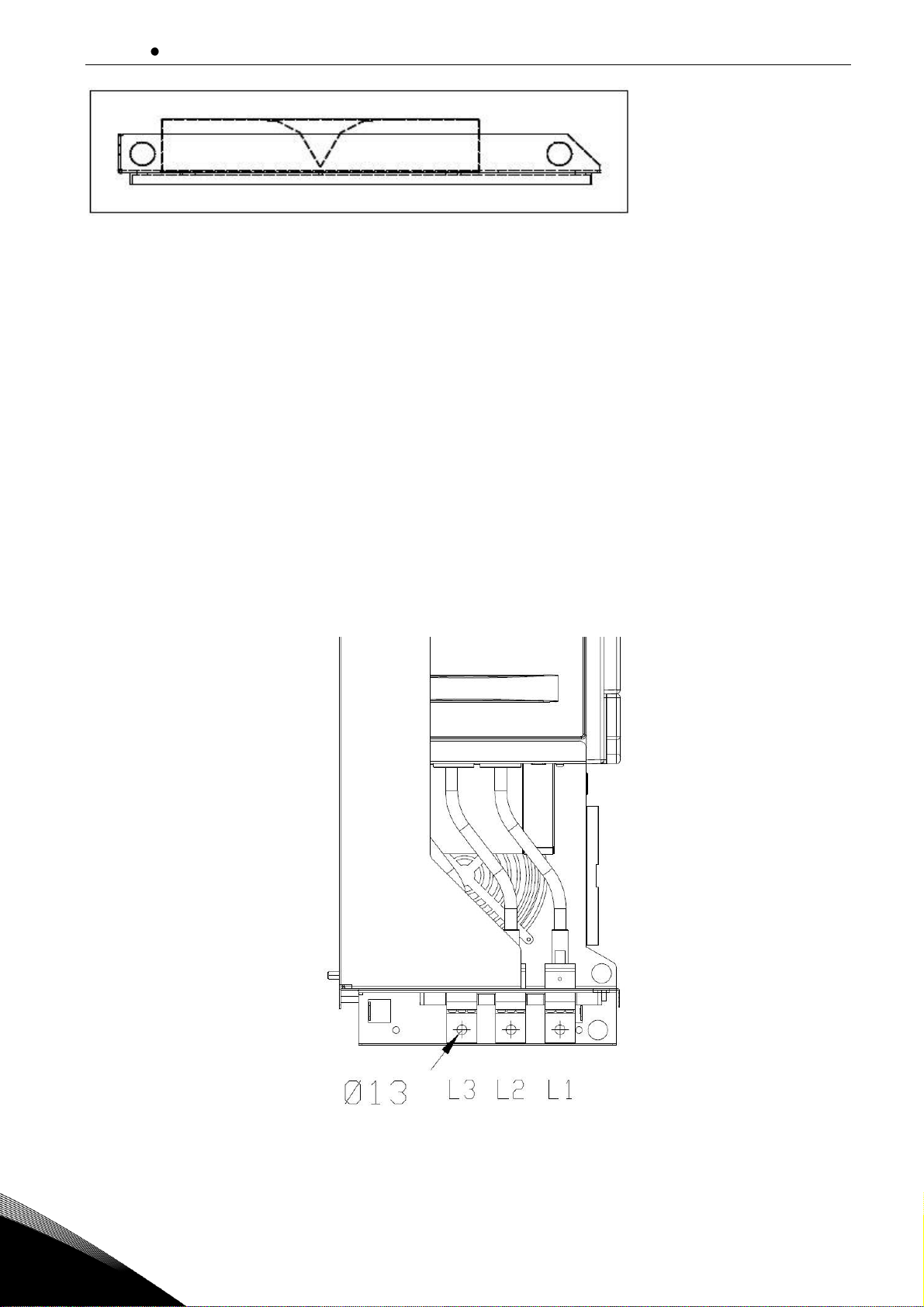
5.3 Power connection
5.3.1
AC connection
The 3-phase input is connected to the input terminals of the AC choke (L1, L2 and L3), see Figure
5-12. Used input terminal are selected by supply voltage. The output terminals of the AC choke (L1,
L2 and L3) are connected to the input terminals of the NFE unit (L1, L2 and L3), see Figure 5-11. The
AC input of the NFE input group must be protected against short circuit. The fuses suitable for protection are shown in Section 4.9. A circuit breaker can also be used for protection, see Section 4.10.
The best short-circuit protection is achieved by using fuses. The short-circuit protection must be on
the input side when seen from the AC choke, Figure 4-2.
A cable or busbar designed for the purpose must be used to make the connection. The connection
must be dimensioned according to the nominal current rating of the Non-Regenerative Front End.
The necessary overloading allowance must also be used. The connection must also have the same
short-circuit capacity as the whole system. The connecting cable or busbar may be of copper or aluminium. When aluminium is used, steps must be taken to prevent corrosion. The dimensions of the
terminals in the unit are indicated in Appendix 7-6.
Figure 5-11. FI9 unit AC connection.
Page 37
Installation vacon 36
Local contacts: https://www.danfoss.com/en/contact-us/contacts-list/
5
Figure 5-12. AC choke connections.
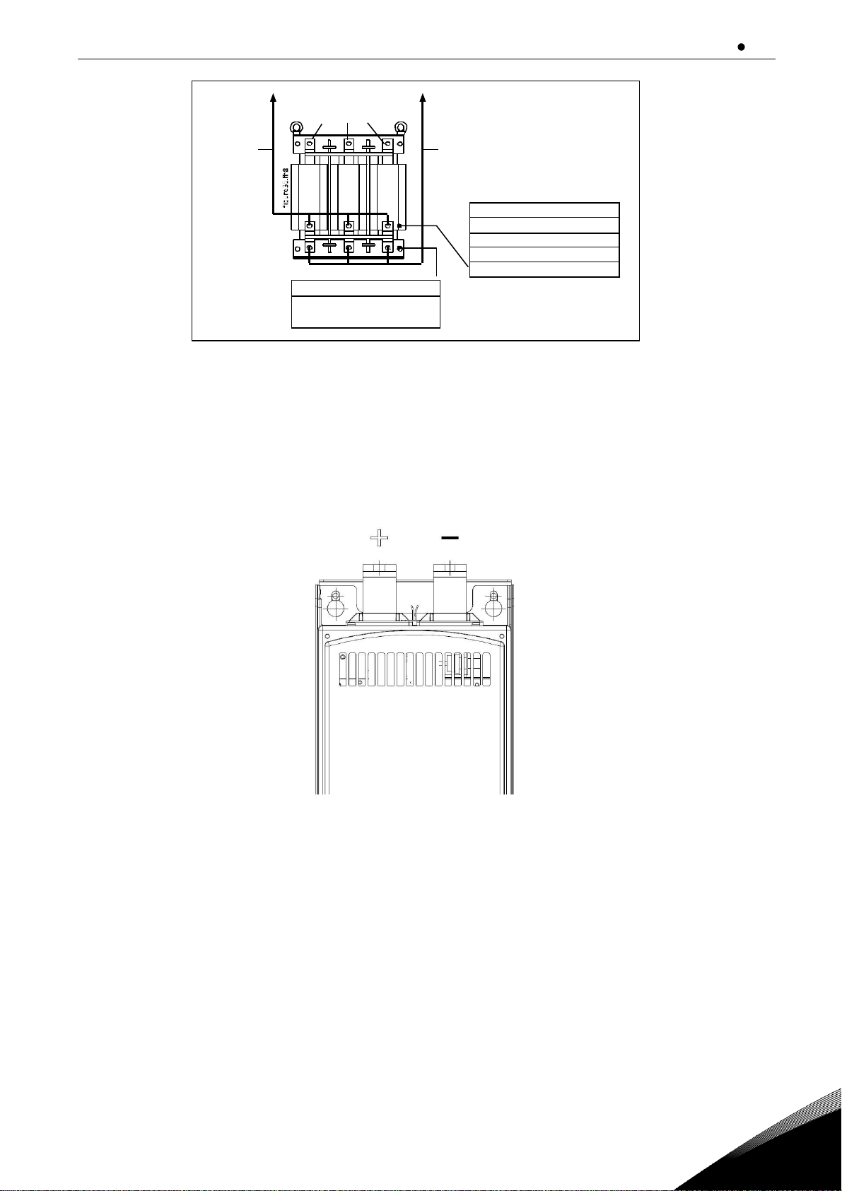
5.3.2
DC connection
The DC connection of the Non-Regenerative Front End unit is connected to the terminals at the top,
see Figure 5-13. The terminals are marked as B+ for connection to DC+ and B- for connection to DC. The DC connection must be protected using DC fuses, see Section 4.9. The terminal dimensions are
shown in Appendix 7-6.
Figure 5-13. FI9 unit DC connection.
5.4 Cable installation and the UL standards
To meet the UL (Underwriters Laboratories) regulations, a UL-approved copper cable with a minimum heat-resistance of +60/75C must be used.
Use Class 1 wire only.
The units are suitable for use on a circuit capable of delivering not more than 100,000 rms
symmetrical amperes, 600 V maximum, or equivalent when protected by class J, T or
Semiconductor fuses.
The tightening torques of the terminals are given below in Table 5-1.
L 1 L 2 L 3 V o l t a g e / F r e q u e n c y V o l t a g
e / F r e q u e n c y 5 0 0 V / 5 0 H z 5 7 5 V / 6 0 H z 6 9 0 V / 5 0 H z 4 0 0 V / 5 0 H z 4 8 0 V / 6 0 H z 5 2 5 V / 5 0 H z C a b l e s / b u s b a r s t o N F E u n i t C a b l e s / b u s b a r
s t o N F E u n i t T e r m i n a l s f o r s u p p l y c a b l e
s
Page 38
vacon 37 Installation
Local contacts: https://www.danfoss.com/en/contact-us/contacts-list/
5
Type
DC terminals
Tightening torque [Nm]
AC terminals
Tightening torque [Nm]
Bolt Ø
Min
Nom
Max
Bolt Ø
Min
Nom
Max
NXN_0650 6
M12
65
70
75
M10
35
40
45
Table 5-1. Tightening torques of terminals
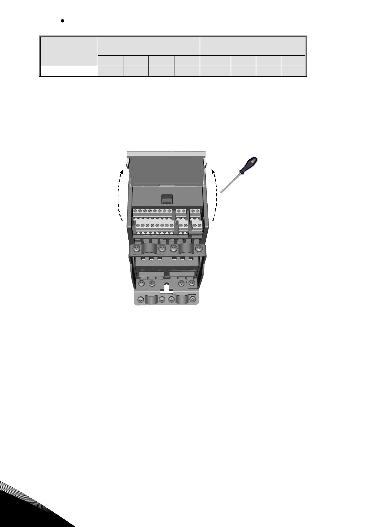
5.5 I/O terminals and I/O signals
I/O terminals can be found under the cover of Control box, see Figure 5-14 and 5-15. Descriptions of
I/O signals see Figure 5-16.
NOTE! Digital signal out is open collector type.
Figure 5-14. Open the cover.
Page 39

Installation vacon 38
Local contacts: https://www.danfoss.com/en/contact-us/contacts-list/
5
Strip the plastic
cable coating for
360°earthing
Control cable
tightening
torque: 0.4 Nm
Figure 5-15. Cabling.
Page 40

vacon 39 Installation
Local contacts: https://www.danfoss.com/en/contact-us/contacts-list/
5
Terminal
Signal
Factory preset
Description
1
+10Vre
Ref. Voltage out
Not used
2
AI1
Analog signal in 1
Not used
3
GND
I/O signal ground
6
24Vout
24V output for DI's
7
GND
I/O signal ground
8
DI1
Digital input 1
0 = STOP
1 = START
9
DI2
Digital input 2
Not used
10
DI3
Digital input 3
1 = RESET
A A RS485 signal A
Not used
B B RS485 signal B
Not used
4
AI2
Analog signal in 2
Not used
5
GND
I/O signal ground
13
GND
I/O signal ground
14
DI4
Digital input 4
Not used
15
DI5
Digital input 5
Not used
16
DI6
Digital input 6
Not used
18
AO
Analog signal out
0 = Not used
1 = DC voltage
2 = Current
20
DO
Digital signal out
0 = Not used
1 = Ready
2 = Running
3 = Fault
4 = Fault inverted
5 = Warning
22
RO11
Relay out 1
0 = Not used
1 = Ready
2 = Running
3 = Fault
4 = Fault inverted
5 = Warning
23
RO12
24
RO21
Relay out 2
0 = Not used
1 = Ready
2 = Running
3 = Fault
4 = Fault inverted
5 = Warning
25
RO22
26
RO23
Figure 5-16. I/O signals.
Page 41

Control keypad vacon 40
Local contacts: https://www.danfoss.com/en/contact-us/contacts-list/
6
6. CONTROL KEYPAD
The control keypad is the link between VACON® NX Non-Regenerative Front End and the user. The
control keypad features an alphanumeric display and indicators for the status (READY, RUN, STOP,
ALARM, FAULT) and four indicators for the active menu (REF, MON, PAR, FLT). There are also three
Status Indica green red).
The control information, i.e. the menu number, description of the menu or the displayed value and
the numeric information are presented on three text lines.
The navigation wheel is used for navigating on the panel display. The wheel has two separate functions;
- rotating the wheel e.g. for changing parameter value (12 steps / round)
- pressing the wheel e.g. for accepting the new value.
Page 42
vacon 41 Control keypad
Local contacts: https://www.danfoss.com/en/contact-us/contacts-list/
6
6.1 Navigation
Hz Hz
FWD REV I/O KEYPAD BUS
REF
MON
PAR
FLT
FAULTALARMSTOPREADY RUN
FWD REV I/O KEYPAD BUS
REF
PAR
FLT
FAULTALARMSTOPREADY RUN
MON
PUSH
FWD REV I/O KEYPAD BUS
REF
PAR
FLT
FAULTALARMSTOPREADY RUN
MON
FWD REV I/O KEYPAD BUS
REF
PAR
FLT
FAULTALARMSTOPREADY RUN
MON
PUSH
FWD REV I/O KEYPAD BUS
REF
PAR
FLT
FAULTALARMSTOPREADY RUN
MON
FWD REV I/O KEYPAD BUS
REF
PAR
FLT
FAULTALARMSTOPREADY RUN
MON
PUSH
FWD REV I/O KEYPAD BUS
REF
PAR
FLT
FAULTALARMSTOPREADY RUN
MON
ROTATE
ROTATE
ROTATE
REFERENCE
MENU
Displays the
keypad reference
value
regardless of
the selected
control place.
MONITORING MENU
In this menu
you can
browse the
monitoring
values.
PARAMETER
MENU
In this menu
you can
browse and
edit the
parameters.
FAULT MENU
Here you will
be able
to browse
through the
faults occurred.
PUSH
FWD REV I/O KEYPAD BUS
REF
MON
PAR
FLT
FAULTALARMSTOPREADY RUN
Figure 6-1. Navigation
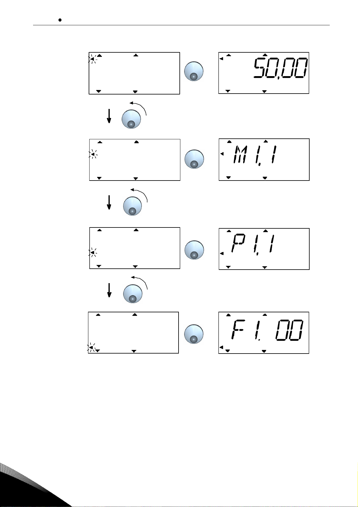
6.1.1
Monitoring menu
Monitoring values mean actual values of measured signals as well as statuses of some control settings. Monitoring values are listed in Table 6-1.
Pushing the navigation wheel once in this menu takes the user to the next level, where the monitoring value, e.g. M1.1 and value is visible (see Figure 6-2). The monitoring values can be browsed by
rolling the navigation wheel clockwise.
Page 43

Control keypad vacon 42
Local contacts: https://www.danfoss.com/en/contact-us/contacts-list/
6
Hz
FAULTALARMSTOPREADY RUN
REF
MON
PAR
FLT
FWD REV I/O KEYPAD BUS
Alternates
in the display
Browse
M1.1 - M1.20
Figure 6-2. Monitoring menu
Code
Parameter
Scale
Unit
Description
M1.1
U_DCLINK
1 V DC voltage
M1.2
IL1 1 A
Current of phase 1
M1.3
IL2 1 A
Current of phase 2
M1.4
IL3 1 A
Current of phase 3
M1.5
UL12
1 V Voltage between phases L1-L2
M1.6
UL23
1 V Voltage between phases L2-L3
M1.7
UL31
1 V Voltage between phases L3-L1
M1.8
Isum
1 A Total average AC current
M1.9
Temp
1
˚C
Unit Temperature
Table 6-1. Monitoring signals.
6.1.2
Parameter menu
In Parameter menu all settable parameters are visible. The parameters can be browsed by rolling
the navigation wheel clockwise. Pushing the navigation wheel once in this menu takes the user to
the next level, where the parameter value, e.g. P3.1 and value is visible (see Figure 6-3). Parameters
are listed below.
The following figure shows the parameter menu view:
Page 44

vacon 43 Control keypad
Local contacts: https://www.danfoss.com/en/contact-us/contacts-list/
6
Hz
FAULTALARMSTOPREADY RUN
REF
MON
PAR
FLT
FWD REV I/O KEYPAD BUS
Alternates
in the display
Browse
P1.1 ->
Push to enter
edit mode
Change
value
Push to
confirm
Figure 6-3. Parameter menu
Digital outputs
Code
Parameter
Min
Max
Default
Unit
Description
P1.1
Relay output 1
0 5 0
0 = Not used
1 = Ready
2 = Running
3 = Fault active
4 = Fault inverted
5 = Warning active
P1.2
Relay output 2
0 5 0
0 = Not used
1 = Ready
2 = Running
3 = Fault active
4 = Fault inverted
5 = Warning active
P1.3
Digital output 1
0 5 0
0 = Not used
1 = Ready
2 = Running
3 = Fault active
4 = Fault inverted
5 = Warning active
Analog outputs
Code
Parameter
Min
Max
Default
Unit
Description
P2.1
Analog output
funtion
0 2 0
0 = Not used
1 = DC voltage
2 = Current
P2.2
Analog output
minimum
0 1 0
0 = 0mA
1 = 4mA
P2.1 Analog output function
If the DC voltage is selected scaling is 0/4mA = 0VDC and 20mA = 1000VDC. If the current is
selected scaling is 0/4mA = 0A and 20mA = 650A.
Page 45

Control keypad vacon 44
Local contacts: https://www.danfoss.com/en/contact-us/contacts-list/
6
NFE parameters
Code
Parameter
Min
Max
Default
Unit
Description
P3.1
Load time
limit
1
20
10
s
P3.2
Over voltage
limit
440
1300
1300
V
P3.3
Over current
limit
51
1014
780
A
P3.1 Load time limit
If the pre-charging is longer than the level set by this parameter then loading time fault is
triggered.
P3.2 Over voltage limit
If the DC link voltage is higher than the level set by this parameter then over voltage fault is
triggered.
P3.3 Over current limit
If the input current is higher than the level set by this parameter then over current fault is
triggered.
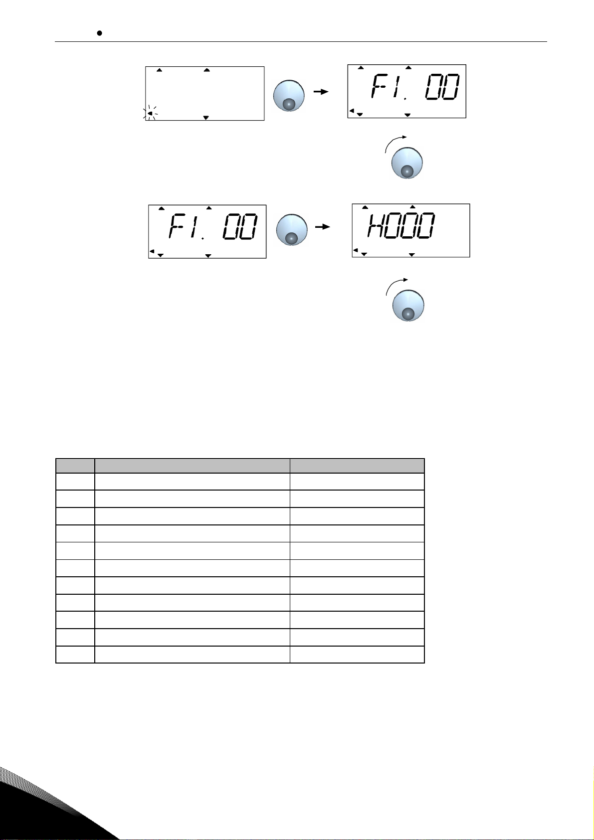
6.1.3
Fault history menu
In Fault history menu you can browse through 9 latest faults (see Figure 6-4). If a fault is active, the
relevant fault number (e.g. F2) alternates in the display with main menu. When you browse between
the faults, the fault codes of active faults are blinking. The active faults can be reset by pressing the
STOP button for 1 second. If the fault cannot be reset, the blinking continues. It is possible to navigate in the menu structure also when there are active faults present, but the display returns automatically to the fault menu if buttons or navigation wheel are not pressed or navigation is not rotated. The operating hour, minute and second values at the fault instant are shown in the value menu
(operating hours = displayed reading x 1000 h). Fault codes are listed in Table 6-2.
Page 46
vacon 45 Control keypad
Local contacts: https://www.danfoss.com/en/contact-us/contacts-list/
6
FAULTALARMSTOPREADY RUN
REF
MON
PAR
FLT
FWD REV I/O KEYPAD BUS
FAULTALARMSTOPREADY RUN
REF
MON
PAR
FLT
FWD REV I/O KEYPAD BUS
FAULTALARMSTOPREADY RUN
REF
MON
PAR
FLT
FWD REV I/O KEYPAD BUS
FAULTALARMSTOPREADY RUN
REF
MON
PAR
FLT
FWD REV I/O KEYPAD
Browse
faults 1-9
Push
Push
Browse
for hours (H),
minutes (M)
and seconds (S)
Figure 6-4. Fault history menu
Note! The whole fault history can be cleared by pressing STOP button for 5 sec time
when the drive is stopped and fault history menu is selected in the display.
Note! If STOP button is pressed for 5 sec and no any menu is selected in the display fac-
tory reset is done. Factory reset set all parameters to default values!
Fault
Description
Default limit value
F1
Over current
780 A
F2
Over voltage
1300 Vdc
F4
Loading time fault
10 s
F8
System Fault
F9
Under voltage
(Supply voltage * 0.8*1.35)
F11
Input phase loss
F13
Under temperature
<-10 / ˚C
F14
Over temperature
>80 / ˚C
F22
EEPROM fault
F32
Fan/Inverter fault
F99
Communication interrupted API/Power
Table 6-2. Fault codes.
Page 47
Control keypad vacon 46
Local contacts: https://www.danfoss.com/en/contact-us/contacts-list/
6
6.1.4
System menu
Code
Parameter
Description
S1.1
API SW ID
S1.2
API SW Version
S1.3
Power SW ID
S1.4
Power SW Version
S1.5
Application SW ID
S1.6
Application SW Version)
S1.7
CPU Load
Table 6-3. System menu signals.
Page 48

vacon 47 Appendices
Local contacts: https://www.danfoss.com/en/contact-us/contacts-list/
7
7. APPENDICES
Appendix 7-1. Circuit diagram for NFE.
Page 49
Appendices vacon 48
Local contacts: https://www.danfoss.com/en/contact-us/contacts-list/
7
Appendix 7-2. Circuit diagram for parallel connected NFE.
Page 50

vacon 49 Appendices
Local contacts: https://www.danfoss.com/en/contact-us/contacts-list/
7
Appendix 7-3. Circuit diagram for 12- pulse solution with NFE.
Page 51
Appendices vacon 50
Local contacts: https://www.danfoss.com/en/contact-us/contacts-list/
7
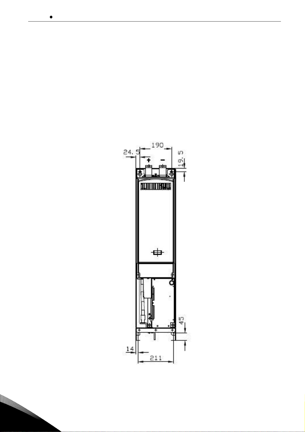
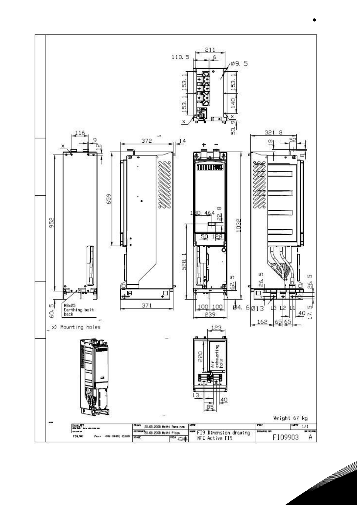
Appendix 7-4. FI9 Dimensions
Page 52
vacon 51 Appendices
Local contacts: https://www.danfoss.com/en/contact-us/contacts-list/
7
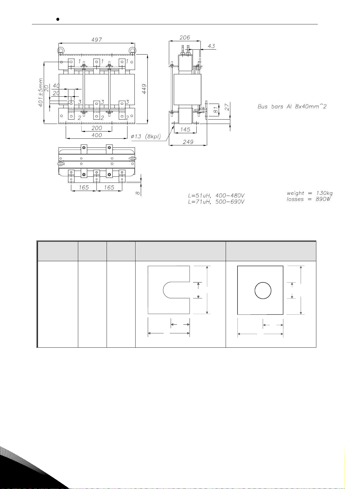
Appendix 7-5. AC choke dimensions
Enclosure
Type
IL
[A]
DC terminal
AC Terminal
NXN_0650 6
FI9
650
PE: M8×25
Appendix 7-6.Terminal sizes for VACON
®
NX Non-regenerative Front End unit.
40
13
35
16
6 x 40
13
38
17
Page 53

www.danfoss.com
Vacon Ltd
Member of the Danfoss Group
Runsorintie 7
65380 Vaasa
Finland
Document ID:
DPD01172C
Rev. C
Sales code: DOC-USERNXNNFE+DLUK
 Loading...