

Page 1

vacon
ac drives
®
nx
apfiff41
Advanced High Speed
application manual
Page 2

Page 3

apfiff41 advanced high speed VACON® • 3
Local contacts: http://drives.danfoss.com/danfoss-drives/local-contacts/
Classified as Public
VACON APFIFF41 APPLICATION MANUAL
INDEX
Document code: DPD01976
Software code: APFIFF41V323
Date: 12.1.2021
1. Advanced HS Application - introduction ................................................................................................................ 8
1.1 General ......................................................................................................................................................... 8
1.2 Basic Features ............................................................................................................................................... 9
2. Version parameter compatibility issues .............................................................................................................. 10
3. Commissioning notes .......................................................................................................................................... 11
3.1 Frequency scale ........................................................................................................................................... 11
3.2 Parameter download ................................................................................................................................... 11
4. Control I/O .......................................................................................................................................................... 12
5. “Terminal To Function” (TTF) programming principle .......................................................................................... 13
5.1 Defining an input/output for a certain function on keypad ........................................................................... 13
5.2 Defining a terminal for a certain function with NCDrive programming tool ................................................... 14
5.3 Defining unused inputs/outputs................................................................................................................... 15
6. Advance HS Application – monitoring values ...................................................................................................... 16
6.1 Monitoring values........................................................................................................................................ 17
6.1.1 Monitoring values 2................................................................................................................................. 18
6.1.2 FieldBus Monitoring values ...................................................................................................................... 19
6.1.3 Activation ................................................................................................................................................ 19
6.1.4 PI Control Monitoring values ................................................................................................................... 19
6.2 Monitoring values description ..................................................................................................................... 20
6.2.1 Monitoring values 2................................................................................................................................. 23
6.2.2 FieldBus Monitoring values ...................................................................................................................... 27
6.2.3 Activation ................................................................................................................................................ 31
6.2.4 PI Control monitoring .............................................................................................................................. 31
7. Parameter list...................................................................................................................................................... 32
7.1 Basic parameters ......................................................................................................................................... 32
7.2 Reference Handling ..................................................................................................................................... 33
7.2.1 Basic Settings .......................................................................................................................................... 33
7.2.2 Constant Reference ................................................................................................................................. 33
7.2.3 Torque Reference .................................................................................................................................... 34
7.2.3.1 Torque Reference OL Settings ......................................................................................................... 34
7.2.3.2 Torque Reference CL Settings .......................................................................................................... 35
7.2.4 Prohibit frequency parameters ................................................................................................................ 35
7.2.5 Motor Potentiometer .............................................................................................................................. 35
7.2.6 Adjust Reference ..................................................................................................................................... 35
7.3 Ramp Control .............................................................................................................................................. 36
7.3.1 Basic Settings .......................................................................................................................................... 36
7.3.2 Ramp Control Options ............................................................................................................................. 36
7.4 Input Signals ................................................................................................................................................ 37
7.4.1 Basic Settings .......................................................................................................................................... 37
7.4.2 Digital inputs ........................................................................................................................................... 38
7.4.3 Analogue input 1 ..................................................................................................................................... 39
7.4.4 Analogue input 2 ..................................................................................................................................... 39
Page 4

4 • VACON® apfiff41 advance high speed
Local contacts: http://drives.danfoss.com/danfoss-drives/local-contacts/
Classified as Public
7.4.5 Analogue input 3 ..................................................................................................................................... 40
7.4.6 Analogue input 4 ..................................................................................................................................... 40
7.4.7 Options ................................................................................................................................................... 40
7.5 Output Signals ............................................................................................................................................. 41
7.5.1 Digital output signals ............................................................................................................................... 41
7.5.2 Analogue output 1 ................................................................................................................................... 42
7.5.3 Analogue output 2 ................................................................................................................................... 43
7.5.4 Analogue output 3 ................................................................................................................................... 43
7.5.5 Delayed digital output 1 .......................................................................................................................... 44
7.5.6 Delayed digital output 2 .......................................................................................................................... 44
7.5.7 Supervision Limits ................................................................................................................................... 45
7.6 Limit Settings ............................................................................................................................................... 45
7.6.1 Current handling ..................................................................................................................................... 45
7.6.2 Power Handling ....................................................................................................................................... 46
7.6.3 Torque Handling ...................................................................................................................................... 47
7.6.3.1 Torque Handling OL Settings ........................................................................................................... 47
7.6.3.2 Torque Handling CL Settings ............................................................................................................ 47
7.6.4 Frequency Handling ................................................................................................................................. 47
7.6.5 DC-Link Handling ..................................................................................................................................... 48
7.6.5.1 DC-Link Handling CL Settings ........................................................................................................... 48
7.7 Flux and DC Current handling....................................................................................................................... 49
7.7.1 Flux and DC Current handling OL Settings ................................................................................................ 49
7.7.2 Flux and DC Current handling CL Settings ................................................................................................. 49
7.8 Motor Control ............................................................................................................................................. 50
7.8.1 Motor Control Basic Settings ................................................................................................................... 50
7.8.2 U/f Settings ............................................................................................................................................. 50
7.8.3 Closed Loop Control Settings ................................................................................................................... 50
7.8.4 PMSM Control settings ............................................................................................................................ 51
7.8.5 Stabilators ............................................................................................................................................... 52
7.8.6 Tuning parameters .................................................................................................................................. 52
7.8.7 Identification parameters ........................................................................................................................ 53
7.8.8 High Speed parameters .......................................................................................................................... 54
7.8.9 Fine tuning parameters ........................................................................................................................... 54
7.9 Speed Control .............................................................................................................................................. 55
7.9.1 Speed Control Basic settings .................................................................................................................... 55
7.9.2 Speed Control OL Settings ....................................................................................................................... 55
7.9.3 Speed Control CL Settings ........................................................................................................................ 55
7.10 Drive Control ............................................................................................................................................... 56
7.11 Master Follower Control Parameters ........................................................................................................... 57
7.12 Protections .................................................................................................................................................. 58
7.12.1 Common settings ................................................................................................................................ 58
7.12.2 Temperature sensor protections ......................................................................................................... 58
7.12.3 Stall Protection.................................................................................................................................... 59
7.12.4 Speed error monitoring ....................................................................................................................... 59
7.12.5 Motor thermal protections .................................................................................................................. 59
7.12.6 Living Zero monitoring ........................................................................................................................ 59
7.12.7 Underload protection .......................................................................................................................... 60
7.12.8 Earth Fault protection ......................................................................................................................... 60
7.12.9 Fieldbus protection ............................................................................................................................. 60
7.12.10 PM Synch Fault ................................................................................................................................... 61
7.12.11 Options ............................................................................................................................................... 61
7.13 Fieldbus parameters .................................................................................................................................... 62
7.13.1 Value Control ...................................................................................................................................... 64
7.13.2 DIN ID Control 1 .................................................................................................................................. 64
7.13.3 Brake Control ...................................................................................................................................... 65
7.13.3.1 Brake Control Start up torque for CL................................................................................................ 65
7.14 Auto reset parameters ................................................................................................................................. 66
Page 5

apfiff41 advanced high speed VACON® • 5
Local contacts: http://drives.danfoss.com/danfoss-drives/local-contacts/
Classified as Public
7.15 PI Control Parameters .................................................................................................................................. 66
7.16 Keypad control (Control keypad: Menu M3) ................................................................................................. 67
7.17 System menu (Control keypad: Menu M6) ................................................................................................... 67
7.18 Expander boards (Control keypad: Menu M7) .............................................................................................. 67
8. Description of parameters................................................................................................................................... 68
8.1 Basic Parameters ......................................................................................................................................... 68
8.2 Reference Handling – “Ref Handling” ........................................................................................................... 76
8.2.1 Basic Parameters ..................................................................................................................................... 77
8.2.2 Constant Reference ................................................................................................................................. 81
8.2.2.1 Inching function .............................................................................................................................. 81
8.2.3 Torque Reference .................................................................................................................................... 82
8.2.3.1 Torque reference OL settings .......................................................................................................... 88
8.2.4 Prohibited frequencies ............................................................................................................................ 89
8.2.5 Motor potentiometer .............................................................................................................................. 90
8.2.6 Adjust Reference ..................................................................................................................................... 91
8.3 Ramp control ............................................................................................................................................... 93
8.3.1 Ramp Options ......................................................................................................................................... 96
8.4 Input signals ................................................................................................................................................ 97
8.4.1 Basic Settings .......................................................................................................................................... 97
8.4.2 Digital inputs ........................................................................................................................................... 99
8.4.2.1 Forced control place ..................................................................................................................... 101
8.4.2.2 Inching function ............................................................................................................................ 102
8.4.3 Analogue Input 1 & 2 ............................................................................................................................. 104
8.4.3.1 Sleep function ............................................................................................................................... 108
8.4.4 Analogue input 3 & 4 ............................................................................................................................. 109
8.4.4.1 Analogue input to any parameter .................................................................................................. 111
8.4.5 Inversion control ................................................................................................................................... 112
8.5 Output signlas ........................................................................................................................................... 113
8.5.1 Digital output signals ............................................................................................................................. 113
8.5.1.1 Brake Control ................................................................................................................................ 114
8.5.1.2 Fieldbus digital inputs connection ................................................................................................. 116
8.5.2 Analogue outputs 1 & 2 & 3 ................................................................................................................... 118
8.5.3 Delayed Digital Output 1 & 2 ................................................................................................................. 122
8.5.4 Supervision limits .................................................................................................................................. 125
8.5.4.1 Analogue input supervision function ............................................................................................. 126
8.6 Limit settings ............................................................................................................................................. 127
8.6.1 Current limit handling............................................................................................................................ 127
8.6.2 Power limit handling ............................................................................................................................. 128
8.6.3 Torque limit handling ............................................................................................................................ 130
8.6.3.1 Motoring torque limit function ...................................................................................................... 130
8.6.3.2 Open Loop settings only ................................................................................................................ 131
8.6.3.3 Closed Loop settings only .............................................................................................................. 131
8.6.4 Frequency limit handling ....................................................................................................................... 132
8.6.5 DC Link handling .................................................................................................................................... 133
8.6.5.1 CL Settigns .................................................................................................................................... 135
8.7 DC current and magnetization handling ..................................................................................................... 136
8.7.1 Open loop settings ................................................................................................................................ 136
8.7.1.1 Flux braking .................................................................................................................................. 139
8.7.2 Closed loop settings .............................................................................................................................. 140
8.8 Motor Control ........................................................................................................................................... 142
8.8.1 U/f Settings ........................................................................................................................................... 145
8.8.1.1 I/f Control ..................................................................................................................................... 148
8.8.2 Close Loop Settings ............................................................................................................................... 149
8.8.3 Permanent magnet synchronous motor settings .................................................................................... 152
8.8.3.1 I/f Control ..................................................................................................................................... 154
8.8.3.2 Flux current controller .................................................................................................................. 155
Page 6

6 • VACON® apfiff41 advance high speed
Local contacts: http://drives.danfoss.com/danfoss-drives/local-contacts/
Classified as Public
8.8.3.3 D and Q axis voltage drops ............................................................................................................ 156
8.8.4 Stabilator settings ................................................................................................................................. 158
8.8.4.1 Torque stabilator .......................................................................................................................... 158
8.8.5 Tuning settings ..................................................................................................................................... 159
8.8.6 Identification settings ........................................................................................................................... 160
8.8.7 High Speed settings .............................................................................................................................. 161
8.8.7.1 Synchronous symmetrical modulation (recommended) ................................................................. 161
8.9 Speed Control settings ............................................................................................................................... 162
8.9.1.1 Open Loop Settings ....................................................................................................................... 163
8.9.1.2 Closed Loop Speed Control Settings .............................................................................................. 163
8.9.1.3 Speed controller tuning for different speed areas .......................................................................... 165
8.9.1.4 Speed controller gain with different loads ..................................................................................... 166
8.10 Drive Control ............................................................................................................................................. 167
8.11 Master Follower ........................................................................................................................................ 171
8.11.1 Master Follower: Standard system ................................................................................................... 171
8.11.2 Master follower configuration ........................................................................................................... 172
8.12 Protections ................................................................................................................................................ 176
8.12.1 General settings ................................................................................................................................ 176
8.12.2 Temperature sensor protections ....................................................................................................... 178
8.12.3 Stall protection ................................................................................................................................. 179
8.12.4 Speed Error ....................................................................................................................................... 181
8.12.5 Motor Protection .............................................................................................................................. 182
8.12.6 4mA Protection ................................................................................................................................. 185
8.12.7 Underload protection ........................................................................................................................ 186
8.12.8 Earth Fault ........................................................................................................................................ 188
8.12.9 Fieldbus communication ................................................................................................................... 189
8.12.9.1 Redundant profibus ...................................................................................................................... 189
8.12.10 Synch Fall Fault ................................................................................................................................. 191
8.13 Fieldbus settings ........................................................................................................................................ 192
8.13.1 General settings ................................................................................................................................ 192
8.14 ID Functions .............................................................................................................................................. 197
8.14.1 Value Control .................................................................................................................................... 197
8.14.2 DIN ID Control ................................................................................................................................... 199
8.15 Brake Control ............................................................................................................................................ 200
8.15.1 Brake monitoring function ................................................................................................................. 204
8.15.2 Closed Loop settings.......................................................................................................................... 205
8.15.2.1 Start Up torque ............................................................................................................................. 205
8.16 Auto Fault Reset ........................................................................................................................................ 206
8.17 Keypad control parameters........................................................................................................................ 209
9. Identification function for permanent magnet synchronous motor .................................................................. 210
9.1 Identification with absolute encoder. ......................................................................................................... 210
9.2 Identification with incremental encoder without Z-pulse input................................................................... 210
9.3 Identification with incremental encoder with Z-pulse input. ....................................................................... 211
10. Status and control words in detail................................................................................................................. 212
10.1 Fieldbus ..................................................................................................................................................... 212
10.1.1 Combination 1, ProfiDrive – Standard with Profibus option board...................................................... 213
10.1.1.1 FB Control Word Combination 1, ProfiDrive – Basic with profibus option board ............................. 213
10.1.1.2 FB Status Word Combination 1, ProfiDrive – Basic with profibus option board ............................... 213
10.1.2 Combination 2, ByPass – ProfiDrive; State Diagram............................................................................ 214
10.1.2.1 State Machine ............................................................................................................................... 215
10.1.2.2 FB Control Word ........................................................................................................................... 216
10.1.2.3 Jogging function ............................................................................................................................ 217
10.1.2.4 FB Status Word ............................................................................................................................. 219
10.1.3 Combination 3, ByPass – Basic ........................................................................................................... 221
10.1.3.1 FB Control Word Combination 3, ByPass – Basic ............................................................................ 221
Page 7

apfiff41 advanced high speed VACON® • 7
Local contacts: http://drives.danfoss.com/danfoss-drives/local-contacts/
Classified as Public
10.1.3.2 FB Status Word Combination 3, ByPass – Basic .............................................................................. 221
11. Problem solving ............................................................................................................................................ 222
12. Fault codes .................................................................................................................................................... 223
Page 8
8 • VACON® apfiff41 Advance HS
Local contacts: http://drives.danfoss.com/danfoss-drives/local-contacts/
1. ADVANCED HS APPLICATION - INTRODUCTION
Software APFIFF41, Advanced High Speed application. This application without license can
go up to 599 Hz. With license maximum frequency is 7200 Hz.
If there is no need to go above 599 Hz its recommended to use APFIF599 Application.
1.1 General This application is not backwards compatible. Please read the application change note or
chapter 2 Version parameter compatibility issues in this application manual to see what
needs to be noted when updating the application. See also the updated parameter
description in NCDrive when commissioning.
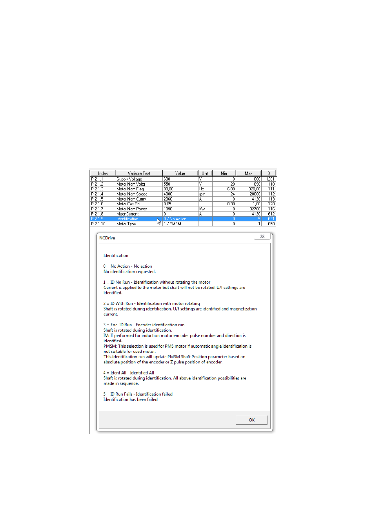
Help is available in NCDrive through selecting “Variable Text” and pressing “F1”.
Below an example from Identification parameter help text from the NCDrive.
Page 9

apfiff41 advanced high speed VACON® • 9
Local contacts: http://drives.danfoss.com/danfoss-drives/local-contacts/
Classified as Public
1.2 Basic Features
This application without license can go up to 599 Hz. With license maximum frequency is
7200 Hz.
Advanced HS application provides a wide range of parameters for controlling motors. It can
be used for various kinds of different processes, where wide flexibility of I/O signals is
needed and PID-control is not necessary (if you need PID-control functions, use the PID
Control Application or Pump and Fan Control Application).
The frequency reference can be selected e.g. from the analogue inputs, joystick control,
motor potentiometer and from a mathematical function of the analogue inputs. There are
parameters also for Fieldbus communication. Multi-step speeds and jogging speed can also
be selected if digital inputs are programmed for these functions.
Additional functions:
• Power limit functions
• Different power limits for motoring and generating side
• Master Follower function
• Different torque limits for motoring and generating side
• Cooling monitor input from heat exchange unit
• Brake monitoring input and actual current monitor for immediate brake close.
• Separate speed control tuning for different speeds and loads
• Inching function two different references
• Possibility to connect the FB Process data to any parameter and some monitoring
values
• Analogue input 3 and 4 can control any parameter by ID number.
• Possibility to control single parameters with digital inputs.
• Redundant Profibus; possibility to connect two PB masters to control same drive,
freezing of control values and changing control slot in case of FBFault.
Page 10

10 • VACON® apfiff41 Advance HS
Local contacts: http://drives.danfoss.com/danfoss-drives/local-contacts/
2. VERSION PARAMETER COMPATIBILITY ISSUES
Compatibility issues V201 to older versions
- FreqRefInterp. TC: ID1780 -> ID1184
- Torque Scale: ID1601 -> ID1247
- DeadTimeComp. ID1580 -> ID1751
- DeadTimeContCurL ID1581 -> id1752
- DeadTHWComp.Disa ID1704 -> id1750
- ContrInSignal ID ID1582 -> id1580
- Contrl Off Limit ID1583 -> ID1581
- Contrl On Limit ID1584 -> ID1582
- Contrl Off Value ID1585 -> ID1583
- Contrl On Value ID1586 -> ID1584
- ControlOutSignID ID1587 -> ID1585
- Control Mode ID1588 -> ID1586
- Control Filt TC ID1589 -> ID1721
- I/f Control Lim ID1608 -> ID1790
- I/f Current ID1609 -> ID1693
- FBFaultDelay ID1500 -> ID1850
- ID Control DI B1 ID1574 -> ID1277
- B10 Value ID1578 -> ID1193
- B11 Value ID1575 -> ID1182
- Ramp Rate ID1579 -> ID1112
- PB SW ID68 -> FB Status Word ID65¨
- TorqStabLimitRat ID1739 -> TorqueStabLimit ID1720
Note 1: When updating application, it is not recommended to use VACON® NCDrive
parameter download function. Instead, upload the parameters from the unit and make
comparison to the old parameter file, especially in cases when version number change is
considerably high. Application is constantly developed, this includes changing parameter
default values. If parameters are directly downloaded to drive, the improved default values
will be lost.
Page 11

apfiff41 advanced high speed VACON® • 11
Local contacts: http://drives.danfoss.com/danfoss-drives/local-contacts/
Classified as Public
3. COMMISSIONING NOTES
3.1 Frequency scale This application support output frequency up to 7200 Hz. License Key is needed to exceed
frequency 599 Hz.
3.2 Parameter download Before downloading parameters to drive it is recommended to select first frequency range
and after that download parameters to drive. Parameter to select frequency range is P2.1.12
Frequency Scale.
Page 12
12 • VACON® apfiff41 Advance HS
Local contacts: http://drives.danfoss.com/danfoss-drives/local-contacts/
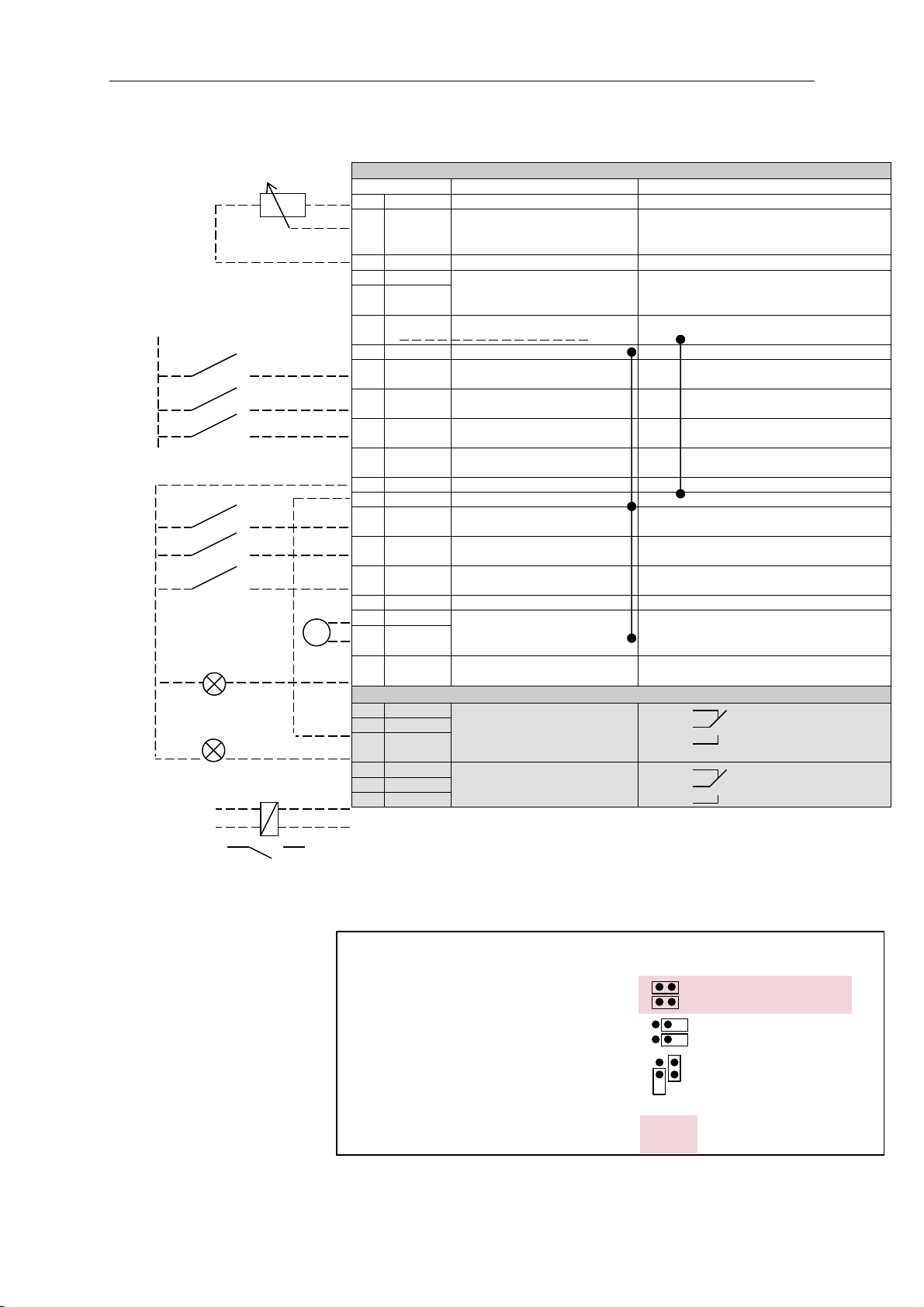
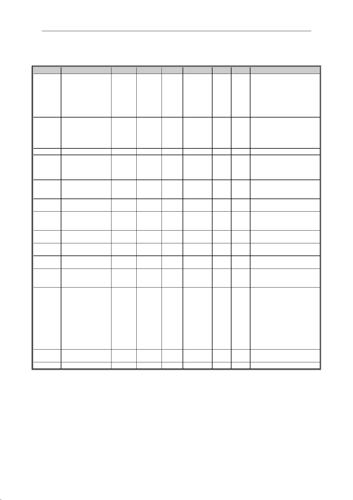
4. CONTROL I/O
NXOPTA1
Terminal
Signal
Description
1
+10V
ref
Reference voltage output
Voltage for potentiometer, etc.
2
AI1+
Analogue input 1.
Range 0-10V, Ri = 200
Range 0-20 mA Ri = 250
Analogue input 1 frequency reference.
Input range selected by jumpers.
Default range: Voltage 0 – 10 V
3
AI1-
I/O Ground
Ground for reference and controls
4
AI2+
Analogue input 2.
Range 0-10V, Ri = 200
Range 0-20 mA Ri = 250
Analogue input 2 frequency reference
Input range selected by jumpers.
Default range: Current 0 – 20 mA
5
AI2-
6
+24V
Control voltage output
Voltage for switches, etc. max 0.1 A
7
GND
I/O ground
Ground for reference and controls
8
DIN1
Start forward
Programmable G2.2.7
Contact closed = start forward
Programmable start logic P2.2.1
9
DIN2
Start reverse
Programmable G2.2.7
Contact closed = start reverse
Programmable logic P2.2.1
10
DIN3
Fault reset
Programmable G2.2.7
Contact open = no fault
Contact closed = fault
11
CMA
Common for DIN 1—DIN 3
Connect to GND or +24V
12
+24V
Control voltage output
Voltage for switches (see #6)
13
GND
I/O ground
Ground for reference and controls
14
DIN4
Programmable G2.2.7
No function defined at default
15
DIN5
Programmable G2.2.7
No function defined at default
16
DIN6
Programmable G2.2.7
No function defined at default
17
CMB
Common for DIN4—DIN6
Connect to GND or +24V
18
AOA1+
Analogue output 1
Programmable P2.3.1.2
Output range selected by jumpers.
Range 0—20 mA. RL, max. 500
Range 0—10 V. RL > 1k
19
AOA1-
20
DOA1
Digital output
Programmable
Open collector, I50mA, U48 VDC
NXOPTA2
21
RO1
Relay output 1
Programmable G2.3.3
Switching capacity
24 VCD / 8 A
250 VAC / 8 A
125 VDC / 0.4 A
22
RO1
23
RO1
24
RO2
Relay output 2
Programmable G2.3.3
Programmable
No function defined at default
25
RO2
26
RO2
Table 4-1. Advance application default I/O configuration and
connection example.
Note: See User Manual, chapter Control Connections, for hardware specification and
configuration.
Note: See jumper selections below.
More information in Vacon NX
User's Manual, Chapter 6.2.2.2.
220
VAC
Jumper block X3:
CMA and CMB grounding
CMB connected to GND
CMA connected to GND
CMB isolated from GND
CMA isolated from GND
CMB and CMA
internally connected together,
isolated from GND
= Factory default
Reference potentiometer,
1…10 k
mA
Page 13
apfiff41 advanced high speed VACON® • 13
Local contacts: http://drives.danfoss.com/danfoss-drives/local-contacts/
Classified as Public
5. “TERMINAL TO FUNCTION” (TTF) PROGRAMMING PRINCIPLE
The programming principle of the input and output signals in the Multipurpose Control
Application NXP as well as in the Pump and Fan Control Application (and partly in the
other applications) is different compared to the conventional method used in other Vacon NX
applications.
In the conventional programming method, Function to Terminal Programming Method (FTT),
you have a fixed input or output that you define a certain function for. The applications
mentioned above, however, use the Terminal to Function Programming method (TTF) in
which the programming process is carried out the other way round: Functions appear as
parameters which the operator defines a certain input/output for. See Warning on page 14.
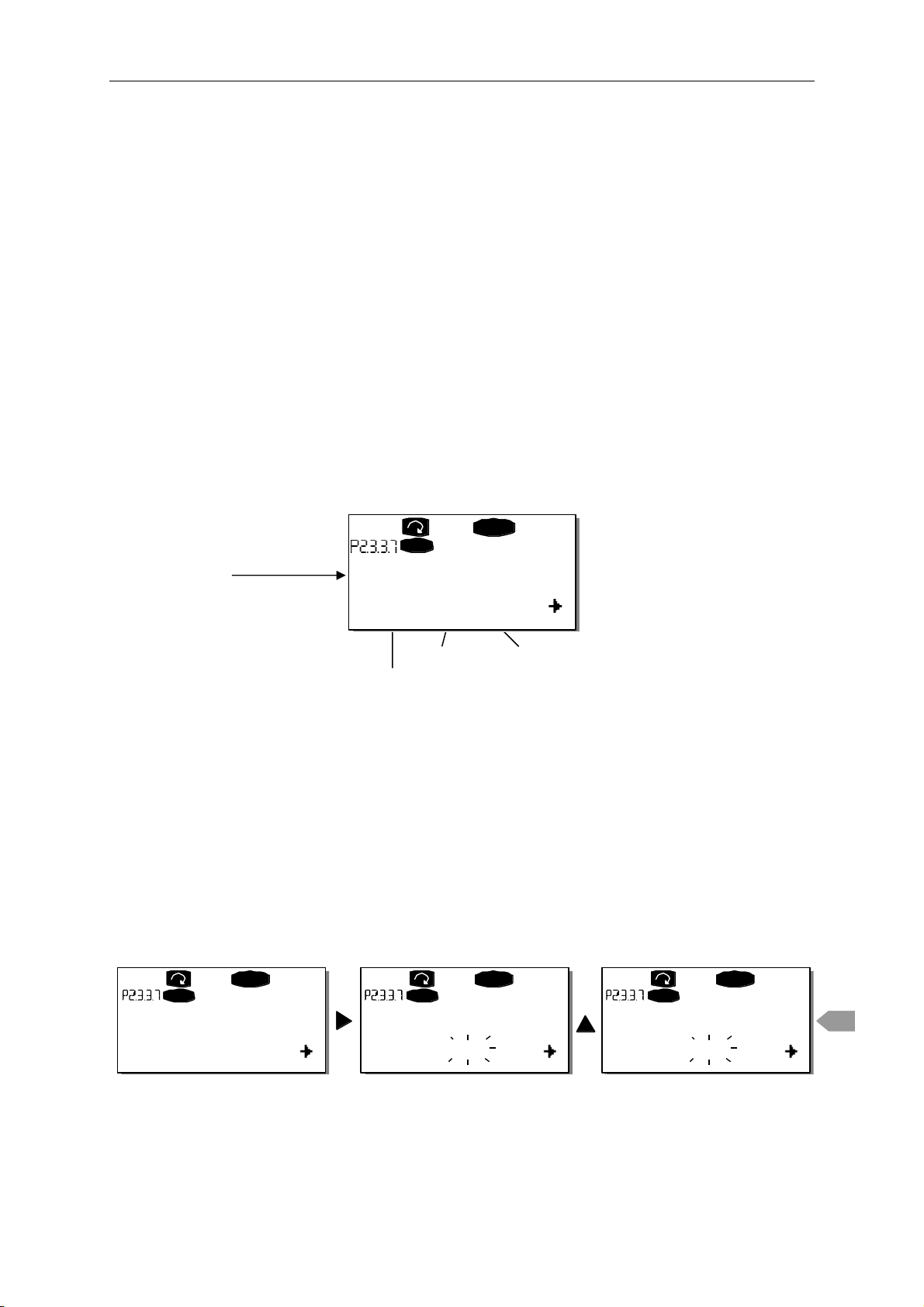
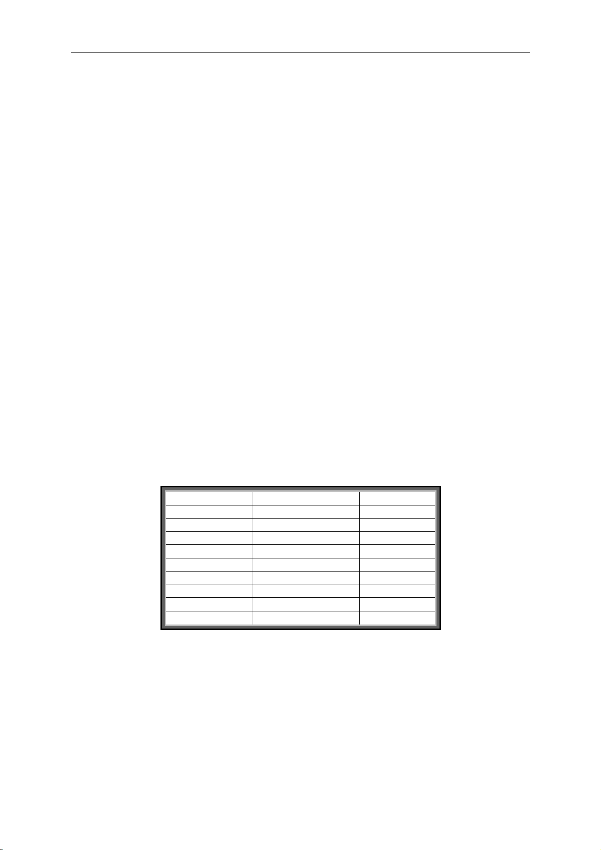
5.1 Defining an input/output for a certain function on keypad Connecting a certain input or output with a certain function (parameter) is done by giving the
parameter an appropriate value. The value is formed of the Board slot on the Vacon NX
control board (see Vacon NX User's Manual, Chapter 6.2) and the respective signal number,
see below.
Function name
Slot Terminal number
Terminal type
Example: You want to connect the digital output function Reference fault/warning
(parameter 2.3.3.7) to the digital output DO1 on the basic board NXOPTA1 (see Vacon NX
User's Manual, Chapter 6.2).
First find the parameter 2.3.3.7 on the keypad. Press the Menu button right once to enter the
edit mode. On the value line, you will see the terminal type on the left (DigIN, DigOUT,
An.IN, An.OUT) and on the right, the present input/output the function is connected to (B.3,
A.2 etc.), or if not connected, a value (0.#).
When the value is blinking, hold down the Browser button up or down to find the desired
board slot and signal number. The program will scroll the board slots starting from 0 and
proceeding from A to E and the I/O selection from 1 to 10.
Once you have set the desired value, press the Enter button once to confirm the change.
READY
I/Oterm
DigOUT:B.1
AI Ref Faul/Warn
READY
I/Oterm
DigOUT:0.0
READY
I/Oterm
DigOUT:0.0
READY
I/Oterm
DigOUT:B.1
enter
AI Ref Faul/Warn AI Ref Faul/Warn AI Ref Faul/Warn
Page 14
14 • VACON® apfiff41 Advance HS
Local contacts: http://drives.danfoss.com/danfoss-drives/local-contacts/
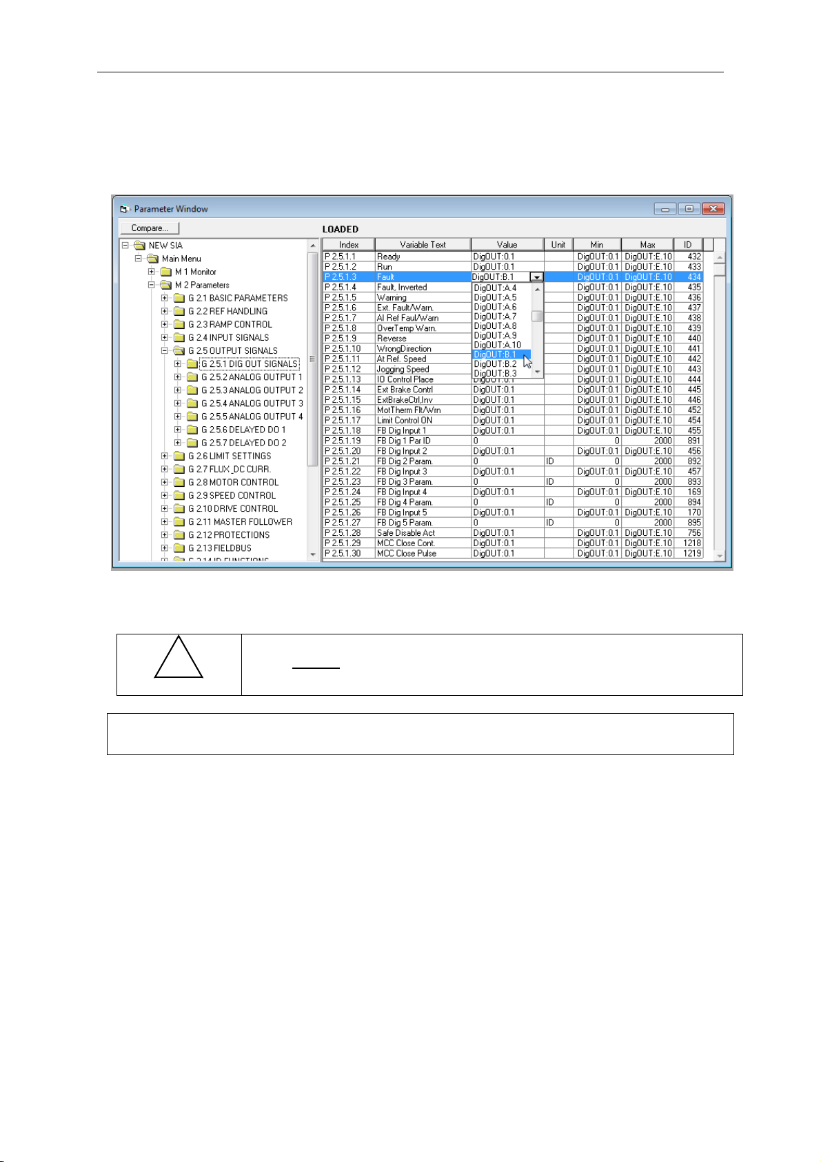
5.2 Defining a terminal for a certain function with NCDrive programming tool If you use the NCDrive Programming Tool for parametrizing you will have to establish the
connection between the function and input/output in the same way as with the control panel.
Just pick the address code from the drop-down menu in the Value column (see the Figure
below).
Figure 5-1. Screenshot of NCDrive programming tool; Entering the address code
Be ABSOLUTELY sure not to connect two functions to one and
same output in order to avoid function overruns and to ensure
flawless operation.
!
WARNING
Note: The inputs, unlike the outputs, cannot be changed in RUN state.
Page 15

apfiff41 advanced high speed VACON® • 15
Local contacts: http://drives.danfoss.com/danfoss-drives/local-contacts/
Classified as Public
5.3 Defining unused inputs/outputs All unused inputs and outputs must be given the board slot value 0 and the value 1 also for
the terminal number. The value 0.1 is also the default value for most of the functions.
However, if you want to use the values of a digital input signal for e.g. testing purposes
only, you can set the board slot value to 0 and the terminal number to any number between
2…10 to place the input to a TRUE state. In other words, the value 1 corresponds to 'open
contact' and values 2 to 10 to 'closed contact'.
In case of analogue inputs, giving the value 1 for the terminal number corresponds to 0%
signal level, value 2 corresponds to 20%, value 3 to 30% and so on. Giving value 10 for the
terminal number corresponds to 100% signal level.
Page 16

16 • VACON® apfiff41 Advance HS
Local contacts: http://drives.danfoss.com/danfoss-drives/local-contacts/
6. ADVANCE HS APPLICATION – MONITORING VALUES
On the next pages you will find the lists of parameters within the respective parameter
groups. The parameter descriptions are given on pages 68 to 205. Parameter description
includes more than is available in this application see parameter list what is available.
Column explanations:
Code = Location indication on the keypad; Shows the operator the present
parameter number
Parameter = Name of parameter
Min = Minimum value of parameter
Max = Maximum value of parameter
Unit = Unit of parameter value; Given if available
Default = Value preset by factory
Cust = Customer’s own setting
ID = ID number of the parameter
_____ = On parameter code: Parameter value can only be changed after the FC
has been stopped.
_____ = Apply the Terminal to Function method (TTF) to these parameters (see
chapter 5)
_____ = Monitoring value is possible to control from fieldbus by ID number
The manual presents signals that are not normally visible for monitoring. i.e. is not a
parameter or standard monitoring signal. These signals are presented with [Letter]. e.g.
[FW]MotorRegulatorStatus
[V] Normal monitoring signal
[P] Normal parameter in application.
[FW] Firmware signal, Can be monitored with NCDrive when signal type is selected
Firmware
[A] Application signal, can be monitored with NCDrive when signal type is selected
Application.
[R] Reference type parameter on keypad.
[F] Function. Signal is received as a output of function.
[DI] Digital input signal.
Page 17
apfiff41 advanced high speed VACON® • 17
Local contacts: http://drives.danfoss.com/danfoss-drives/local-contacts/
Classified as Public
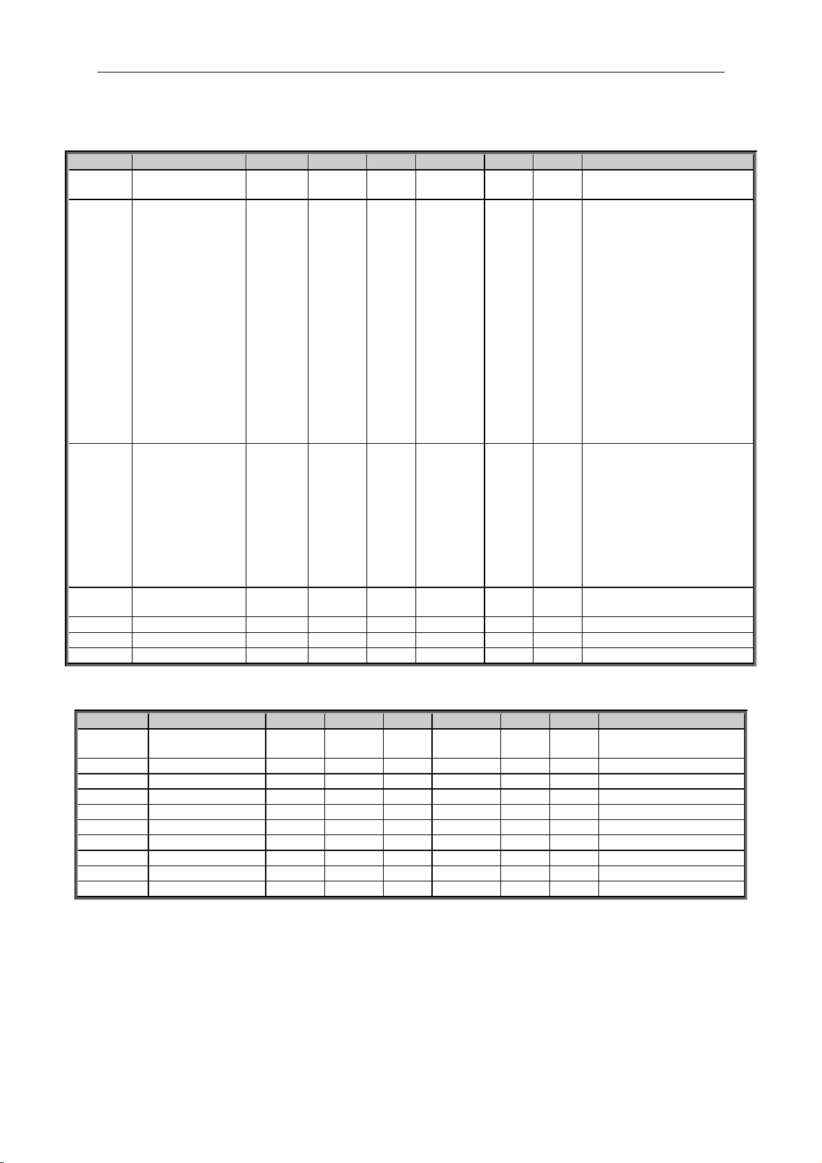
6.1 Monitoring values The monitoring values are the actual values of parameters and signals as well as statuses
and measurements.
Code
Parameter
Unit
Form.
ID
Description
V1.1
Output frequency
Hz
#,##
1
Output frequency to motor
V1.2
Frequency reference
Hz
#,##
25
Frequency reference to motor control
V1.3
Motor speed
rpm # 2
Motor speed in rpm
V1.4
Motor current
A
Varies
3
1 s linear filtering
V1.5
Motor torque
%
#,#
4
In % of Motor nominal torque
V1.6
Motor Power
%
#,#
5 V1.7
Motor voltage
V
#,#
6
Calculated motor voltage
V1.8
DC link voltage
V # 7
Measured DC voltage, filtered.
V1.9
Unit temperature
C
# 8 Heatsink temperature
V1.10
Motor temperature
%
#
9
Calculated motor temperature
V1.11
Analogue input 1
%
#,##
13
AI1, unfiltered.
V1.12
Analogue input 2
%
#,##
14
AI2, unfiltered.
V1.13
Analogue input 3
%
#,##
27
AI3, unfiltered.
V1.14
Analogue input 4
%
#,##
28
AI4, unfiltered.
V1.15
Analogue Out 1
%
#,##
26
AO1
V1.16
Analogue Out 2
%
#,##
31
AO2
V1.17
Analogue Out 3
%
#,##
32
AO3
V1.18
DIN1, DIN2, DIN3
15
Digital input statuses
V1.19
DIN4, DIN5, DIN6
16
Digital input statuses
V1.20
Torque reference
%
#,#
18
Used Torque Reference
V1.21
Sensor Max
Temperature
Cº
#,#
42
Highest temperature of OPTB8 board. 4 s
filtering.
G1.22
Multimonitoring items
Displays three selectable monitoring
values
Table 6-1. Monitoring values
Page 18

18 • VACON® apfiff41 Advance HS
Local contacts: http://drives.danfoss.com/danfoss-drives/local-contacts/
6.1.1 Monitoring values 2
Code
Parameter
Unit
Form.
ID
Description
V1.23.1
Current
A
Varies
1113
Unfiltered motor current
V1.23.2
Torque
%
#,#
1125
Unfiltered motor torque
V1.23.3
DC Voltage
V # 44
Unfiltered DC link voltage
V1.23.4
Application Status
Word
43
V1.23.5
Encoder 1 Frequency
Hz
#,##
1124
Unfiltered
V1.23.6
Output Power
kw
Varies
1508
Unfiltered electrical power
V1.23.7
Measured temperature
1
Cº
#,#
50
4 s filtering.
V1.23.8
Measured temperature
2
Cº
#,#
51
4 s filtering.
V1.23.9
Measured temperature
3
Cº
#,#
52
4 s filtering.
V1.23.10
Measured temperature
4
Cº
#,#
69
4 s filtering.
V1.23.11
Measured temperature
5
Cº
#,#
70
4 s filtering.
V1.23.12
Measured temperature
6
Cº
#,#
71
4 s filtering.
V1.23.13
ABS Encoder
Revolutions
r
#
55
V1.23.14
ABS Encoder Position
#
54
V1.23.15
Actual Torque
Reference
%
#,#
Final torque reference from speed
control and/or torque control
V1.23.16
Final Frequency
Reference
Hz
#,##
1131
Final reference to speed controller.
V1.23.17
Step response
Hz
#,##
1132
V1.23.18
Encode 2 Frequency
Hz
#,##
53
V1.23.19
ID Run Status
49
V1.23.20
Pole Pair Number
58
V1.23.21
CosPhiiActual
#,###
68
V1.23.22
PowerAngle
Deg
1617
V1.23.23
PeakMagnetFlux
1618
V1.23.24
Identfail
98 V1.23.25
Non Ready Cause
#
1608
V1.23.26
Prevent MC Ready
#
1609
Table 6-2. Monitoring values 2
Page 19
apfiff41 advanced high speed VACON® • 19
Local contacts: http://drives.danfoss.com/danfoss-drives/local-contacts/
Classified as Public
6.1.2 FieldBus Monitoring values
Code
Parameter
Unit
Form.
ID
Description
V1.24.1
FB Control Word
1160
V1.24.2
FB Status Word
65 V1.24.3
FB Torque Reference
%
#,#
1140
Default Control of FB PD 1
V1.24.4
FB Limit Scaling
%
#,##
46
Default Control of FB PD 2
V1.24.5
FB Adjust Reference
%
#,##
47
Default Control of FB PD 3
V1.24.6
FB Analog Output
%
#,##
48
Default Control of FB PD 4
V1.24.7
FB Motor Current
A
#,#
45
Motor current (drive
independent) given with one
decimal point
V1.24.8
Fault Word 1
1172
V1.24.9
Fault Word 2
1173
V1.24.10
Warning Word 1
1174
V1.24.11
Last Active Fault
37 V1.24.12
Din Status Word
56
V1.24.13
Din Status Word 2
57
V1.24.14
MC Status
64 V1.24.15
Last Active Warning
74 V1.24.16
Shaft Rounds
1170
V1.24.17
Shaft Angle
1169
Table 6-3. FieldBus Monitoring values
6.1.3 Activation
Code
Parameter
Unit
Form.
ID
Description
V1.25.1
SN CRC
1997
Serial number key
6.1.4 PI Control Monitoring values
Code
Parameter
Unit
Form.
ID
Description
V1.26.1
PI Reference
20
Used PI Reference
V1.26.2
PI Actual Value
21
PI Actual value
V1.26.3
PI Output
23
PI Output before scaling
V1.26.4
PI Output Scaled
1807
Scaled PI Output
This is used for ID connection
Page 20
20 • VACON® apfiff41 Advance HS
Local contacts: http://drives.danfoss.com/danfoss-drives/local-contacts/
6.2 Monitoring values description
V1.1 Output frequency [#,## Hz] ID1
Output frequency to motor, updated at 10 ms time level.
V1.2 Frequency reference [#,## Hz] ID 25
Frequency reference to motor control, after speed share function. updates at 1
ms time level.
V1.3 Motor speed [ # rpm] ID 2
Motor speed in rpm
V1.4 Motor current [A] ID 3
Open loop:
1 s linear filtering.
Closed Loop:
32 ms filtering
Drive Synch Operation Master drive
This value is the total current of the system divided by number of drives in the
system (SbLastID). SbLastId cannot be changed; it needs to be set according to
how many drives are linked with system bus.
Drive Synch Operation Follower drive
This value is the current of the drive’s own power unit.
Current scaling in different size of units
Note: ID45, usually in Process data OUT 3 is scaled to be with one decimal
always.
Voltage
Size
Scale
208 – 240 Vac
NX0001 – NX0011
100 – 0,01A
208 – 240 Vac
NX0012 – NX0420
10 – 0,1A
208 – 240 Vac
NX0530
1 – 1A
380 – 500 Vac
NX0003 – NX0007
100 – 0,01A
380 – 500 Vac
NX0009 – NX0300
10 – 0,1A
380 – 500 Vac
NX0385 – NX2643
1 – 1A
525 – 690 Vac
NX0004 – NX0013
100 – 0,01A
525 – 690 Vac
NX0018 – NX0261
10 – 0,1A
525 – 690 Vac
NX0325 – NX1500
1 – 1A
V1.5 Motor torque % ID 4
In % of Motor nominal torque
Page 21

apfiff41 advanced high speed VACON® • 21
Local contacts: http://drives.danfoss.com/danfoss-drives/local-contacts/
Classified as Public
Open loop
1 s linear filtering
Closed Loop
32 ms filtering
Drive Synch Operation Follower drive
This value is the torque of the drive’s own power unit related to set motor
nominal current.
V1.6 Motor Power % ID 5
Calculated motor power
V1.7 Motor voltage V ID 6
Calculated motor voltage
V1.8 DC link voltage V ID 7
Measured DC voltage, filtered.
V1.9 Unit temperature C ID 8
Heatsink temperature
V1.10 Motor temperature % ID 9
Calculated motor temperature
105 % is tripping limit if response is fault.
V1.11 Analogue input 1 % ID 13
V1.12 Analogue input 2 % ID 14
Unfiltered analogue input level.
0 % = 0 mA / 0 V, -100 % = -10 V, 100 % = 20 mA / 10 V.
Monitoring scaling is determined by the option board parameter.
V1.13 Analogue input 3 % ID 27
V1.14 Analogue input 4 % ID 28
It is possible to adjust this input value from fieldbus when the input terminal
selection is 0.1. This way it is possible to adjust the free analogue input from
fieldbus and have all analogue input functions available for fieldbus process
data.
V1.15 Analogue Out 1 % ID 26
V1.16 Analogue Out 2 % ID 50
V1.17 Analogue Out 3 % ID 51
Analogue Output value 0 % = 0 mA / 0 V, 100 % = 20 mA / 10 V
Page 22

22 • VACON® apfiff41 Advance HS
Local contacts: http://drives.danfoss.com/danfoss-drives/local-contacts/
V1.18 DIN1, DIN2, DIN3 ID 15
V1.19 DIN4, DIN5, DIN6 ID 16
DIN1/DIN2/DIN3 status
DIN4/DIN5/DIN6 status
b0
DIN3
DIN6
b1
DIN2
DIN5
b2
DIN1
DIN4
V1.20 Torque reference % ID 18
Torque reference value before load share.
V1.21 PT-100 Temperature Cº ID 42
Highest temperature of OPTB8 board. 4 s filtering.
Page 23

apfiff41 advanced high speed VACON® • 23
Local contacts: http://drives.danfoss.com/danfoss-drives/local-contacts/
Classified as Public
6.2.1 Monitoring values 2
V1.23.1 Current A ID 1113
Unfiltered motor current, recommended signal for NCDrive monitoring.
Drive Synch Operation Master drive
This value is the total current of the system divided by number of drives in the
system (SbLastID). SbLastId cannot be changed; it needs to be set according to
how many drives are linked with system bus.
Drive Synch Operation Follower drive
This value is current of drive own power unit.
V1.23.2 Torque % ID 1125
Unfiltered motor torque, recommended signal for NCDrive monitoring.
V1.23.3 DC Voltage V ID 44
Unfiltered DC link voltage, recommended signal for NCDrive monitoring.
V1.23.4 Application Status Word ID 43
Application Status Word combines different drive statuses to one data word.
Recommended signal for NCDrive monitoring.
Application Status Word ID43
FALSE
TRUE
b0
Flux not ready
Flux ready (>90 %)
b1
Not in Ready state
Ready
b2
Not Running
Running
b3
No Fault
Fault
b4
Direction Forward
Direction Reverse
b5
Emergency Stop Active
Emergency Stop NOT Active
b6
Run Disabled
Run Enable
b7
No Warning
Warning
b8
b9
b10
b11
No DC Brake
DC Brake is active
b12
No Run Request
Run Request
b13
No Limit Controls Active
Limit control Active
b14
External Brake Control OFF
External Brake Control ON
b15
V1.23.5 Encoder 1 Frequency Hz ID 1124
Encoder frequency after filter. P2.8.4.6 Encoder1FiltTime.
V1.23.6 Output Power kw ID 1508
Unfiltered electrical drive output power.
Page 24

24 • VACON® apfiff41 Advance HS
Local contacts: http://drives.danfoss.com/danfoss-drives/local-contacts/
V1.23.7 Measured temperature 1 Cº ID 50
V1.23.8 Measured temperature 2 Cº ID 51
V1.23.9 Measured temperature 3 Cº ID 52
V1.23.10 Measured temperature 4 Cº ID 69
V1.23.11 Measured temperature 5 Cº ID 70
V1.23.12 Measured temperature 6 Cº ID 71
Separate measurement from two PT100 board. The signal has 4 s filtering time.
V1.23.13 ABS Encoder Revolutions ID55
Absolute encoder revolution information.
V1.23.14 ABS Encoder Position ID54
Absolute encoder position within one rotation. See encoder manual for scaling.
V1.23.15 Actual Torque Reference % ID1180
Final torque reference from speed control and torque control. Also includes
torque step and acceleration compensation factors.
V1.23.16 Final Frequency Reference Hz ID 1131
Final reference to speed controller. After ramp generator and after Speed Step
function, used for closed loop speed tuning when used together with Encoder 1
frequency.
V1.23.17 Step response Hz ID 1132
Frequency error. Compares ramp output to actual encoder frequency with 0,001
Hz accuracy. Can be used for speed control tuning in closed loop control.
V1.23.18 Encoder 2 Frequency ID 53
Estimated Cos Phii.
V1.23.19 ID Run Status ID49
Status of identification run. Bits are set if items are done successfully.
V1.23.20 Pole Pair Number ID58
Pole pair number of the motor.
V1.23.21 CosPhiiActual ID 68
Estimated Cos Phii.
V1.23.22 Power Angle Deg ID 1617
V1.23.23 Peak Magnet Flux ID 1618
Page 25

apfiff41 advanced high speed VACON® • 25
Local contacts: http://drives.danfoss.com/danfoss-drives/local-contacts/
Classified as Public
V1.23.24 Ident Failure Code [Ident Fail. Code] ID 98
Failure code for failed identification:
1 = Current measurement offset
2 = Identification current level
3 = Acceleration time too long
4 = Identification frequency reference not reached
5 = Too low or high magnetization current
6 = Flux curve outside expected levels
7 = PMSM, Encoder zero position
8 = Too low maximum frequency limit
9 = PMSM, encoder zero pulse not found.
10 = Ls Identification timeout
11 = Ls Identification current
V1.23.25 Non Ready Cause ID 1608
Non Ready Cause ID1608
Signal
b0
Fault is Active
b1
PreventMCReady is set
b2
Charge switch is open
b3
DC Voltage not OK
b4
Power unit state not OK
b5
StartUp Wizard is active
b6
Run Enable is not set
b7
Ready state prevented by STO
b8
b9
b10
b11
b12
b13
b14
b15
Page 26

26 • VACON® apfiff41 Advance HS
Local contacts: http://drives.danfoss.com/danfoss-drives/local-contacts/
V1.23.26 Prevent MC Ready ID 1609
Prevent MC Ready ID1609
Signal
b0
Endat option board (OPTBB, OPTBE) communication is not initialized
after power-up.
b1
Drive sync master has wrong modulator or 1000ms task parameters
are not initialized
b2
Drive sync follower delay is active
b3
Drive sync failure in sw modulator double period mode
b4
Charge switch delay is active
b5
AFE fast run disable through ENC C1 is active
b6
100ms task not executed
b7
b8
b9 b10 b11 b12 b13 b14 b15
Page 27

apfiff41 advanced high speed VACON® • 27
Local contacts: http://drives.danfoss.com/danfoss-drives/local-contacts/
Classified as Public
6.2.2 FieldBus Monitoring values
V1.24.1 FB Control Word ID1160
Control word used in bypass mode. See P2.13.22 and option board ByPass.
Bit
Description
Value = 0
Value = 1
0
OFF
ON, Reset after Fault or b1 and b2
1
Emergency stop by coast
ON, On normal operation: Keep TRUE
2
Emergency stop by ramp
ON, On normal operation: Keep TRUE
3
STOP REQUEST
RUN REQUST
4
Force ramp to Zero
Enable Ramp,
5
Freeze Ramp
Enable Ramp,
6
Force Ref to Zero
Enable Ramp,
7
No Action
FAULT RESET (0 -> 1)
8
No Action
Inching 1
9
No Action
Inching 2
10
Disable Profibus control
Enable Profibus control
11
Fieldbus DIN1=OFF
Fieldbus DIN1=ON (Watchdog pulse)
12
Fieldbus DIN2=OFF
Fieldbus DIN2=ON
13
Fieldbus DIN3=OFF
Fieldbus DIN3=ON
14
Fieldbus DIN4=OFF
Fieldbus DIN4=ON
15
No Action
No Action
V1.24.2 FB Status Word ID65
Profibus type status word. Generated in the application level.
Needs to be selected with P2.14.19 GSW to be used. When needed with
profibus board, operation mode needs to be set to ByPass in option board and
with P2.14.22 ProfiBus Mode select: 2 / ProfiDrive.
Bit
Description
Value = 0
Value = 1
0
Not ready to switch on
Ready to switch on
1
Not ready to operate
Ready to operate
2
Not Running
Running
3
No Fault
Fault
4
Coast stop Active
Coast stop not active
5
Quick stop active
Quick stop not active
6
Switch not inhibited
Switch on inhibit
7
No Warning
Warning
8
Speed error
Speed At Reference
9
No FB Control request
FB Control Active
10
Fout < Fmax
Fout > Fmax
11
not used
not used
12
not used
not used
13
not used
not used
14
not used
not used
15
Fieldbus DIN1=OFF
Fieldbus DIN1=ON (Watchdog pulse)
Page 28

28 • VACON® apfiff41 Advance HS
Local contacts: http://drives.danfoss.com/danfoss-drives/local-contacts/
V1.24.3 FB Torque Reference % ID 1140
Torque reference value from fieldbus
Default Control of FB PD 1
V1.24.4 FB Limit Scaling % ID 46
Limit scaling input value from fieldbus.
Default Control of FB PD 2.
V1.24.5 FB Adjust Reference % ID 47
Reference adjustment value from fieldbus.
Default Control of FB PD 3.
V1.24.6 FB Analog Output % ID 48
Fieldbus value to control analogue output.
Default Control of FB PD 4.
V1.24.7 FB Motor Current A ID 45
Motor current (drive independent) given with one decimal point.
V1.24.8 Fault Word 1 ID 1172
Different faults are collected to two words that can be read from fieldbus or with
NCDrive PC software.
Fault Word 1 ID1172
Fault
Comment
b0
Over Current or IGBT
F1, F31, F41
b1
Over Voltage
F2
b2
Under Voltage
F9
b3
Motor Stalled
F15, F80
b4
Earth Fault
F3
b5
Motor Under Load
F17
b6
Drive over temperature
F14
b7
Over Temperature
F16, F56, F29
b8
Input Phase
F10
b9
Brake resistor over temperature
F42
(Not implemented)
b10
Device Changed
F37, F38, F39, F40, F44, F45
(Not implemented)
b11
Keypad or PCControl
F52
b12
FielBus
F53
b13
SystemBus
F59
b14
Slot
F54
b15
4 mA
F50
Page 29
apfiff41 advanced high speed VACON® • 29
Local contacts: http://drives.danfoss.com/danfoss-drives/local-contacts/
Classified as Public
V1.24.9 Fault Word 2 ID 1173
Fault Word 2 ID1173
Fault
Comment
b0
Output phase
F11 (Not implemented)
b1
Charge Switch
F5 (Not implemented)
b2
Encoder
F43
b3
Inverter
F4, F7 (Not implemented)
b4
Reserved
b5
EEPROM
F22 (Not implemented)
b6
External
F51
b7
Brake Chopper
F12 (Not implemented)
b8
Watch Dog
F25 (Not implemented)
b9
IGBT
F31, F41
b10
Brake
F58
b11
Fan Cooling
F32
b12
Application
F35 (Not implemented)
b13
Control fault
F33, F36, F8 (Not implemented)
b14
Main Switch Open
F64 (Not implemented)
b15
Reserved
V1.24.10 Warning Word 1 ID 1174
Warning Word 1 ID1174
Fault
Comment
b0
Motor stalled
W15, W80
b1
Motor over temperature
W16
b2
Motor under load
W17
b3
Input phase loss
W10
b4
Output phase loss
W11 (Not implemented)
b5
Safe disable
W30 (Not implemented)
b6
FieldBus communication fault in slot D
W53
b7
FieldBus communication fault in slot E
W67
b8
Drive over temperature
W14
b9
Analogue input < 4mA
W50 (Not implemented)
b10
Reserved
b11
Emergency stop
W63 (Not implemented)
b12
Run disabled
W62 (Not implemented)
b13
Not used
b14
Mechanical Brake
W58
b15
Reserved
Page 30
30 • VACON® apfiff41 Advance HS
Local contacts: http://drives.danfoss.com/danfoss-drives/local-contacts/
V1.24.11 Fault History ID 37
Fault number of the last active fault.
V1.24.12 Din Status Word ID 56
V1.24.13 Din Status Word 2 ID 57
DIN StatusWord 1
DIN StatusWord 2
b0
DIN: A.1
DIN: C.5
b1
DIN: A.2
DIN: C.6
b2
DIN: A.3
DIN: D.1
b3
DIN: A.4
DIN: D.2
b4
DIN: A.5
DIN: D.3
b5
DIN: A.6
DIN: D.4
b6
DIN: B.1
DIN: D.5
b7
DIN: B.2
DIN: D.6
b8
DIN: B.3
DIN: E.1
b9
DIN: B.4
DIN: E.2
b10
DIN: B.5
DIN: E.3
b11
DIN: B.6
DIN: E.4
b12
DIN: C.1
DIN: E.5
b13
DIN: C.2
DIN: E.6
b14
DIN: C.3
b15
DIN: C.4
V1.24.14 MC Status ID 64
This is the value that is also send to fieldbus on those fieldbus that do not use
own state machine.
Motor Control Status Word
FALSE
TRUE
b0
Not in Ready state
Ready
b1
Not Running
Running
b2
Direction Clockwise
Counterclockwise
b3
No Fault
Fault
b4
No Warning
Warning
b5 At reference speed
b6 At Zero Speed
b7 Flux Ready
b8 TC Speed Limiter Active
b9
Encoder Direction
Counterclockwise
b10 Under Voltage Fast stop
b11
No DC brake
DC Brake is active
b12
b13 Restart delay active
b14
b15
V1.24.15 Warning ID 74
Last active warning.
Page 31

apfiff41 advanced high speed VACON® • 31
Local contacts: http://drives.danfoss.com/danfoss-drives/local-contacts/
Classified as Public
V1.24.16 Shaft Rounds ID 1170
Rounds information from incremental encoder. The value is reset when 24 Vdc is
removed from the drive.
V1.24.17 Shaft Angle ID 1169
Angle information from incremental encoder. The value is reset when 24 Vdc is
removed from the drive.
6.2.3 Activation
V1.25.1 SN CRC ID1997
Serial number key of power unit
6.2.4 PI Control monitoring
This PI control uses ID numbers for input and output signal. See detail in PI Control chapter.
V1.26.1 PI Reference ID20
Used PI Reference, reference is selected by ID number.
V1.26.2 PI Actual Value ID21
PI Actual value. Actual input is selected by ID number.
V1.26.3 PI Output ID23
PI Output before scaling. This value uses PI Out High and Low for limiting.
V1.26.4 PI Output Scaled ID1807
Scaled PI Output.
This is used for ID connection. Scaling function is used to scale value more
suitable for connected signal. e.g. when output is connected to torque limit actual
value need to be -1000 ...+1000 (-100,0 %..+100,0 %) But PI Out High and Low
can be from -30000...+30000 to have more accurate PI control.
Page 32
32 • VACON® apfiff41 Advance HS
Local contacts: http://drives.danfoss.com/danfoss-drives/local-contacts/
7. PARAMETER LIST
7.1 Basic parameters
Code
Parameter
Min
Max
Unit
Default
Cust
ID
Note
P2.1.1
Frequency Scale
0 6 1
523
0 = 0,000 – 32,000 Hz
1 = 0,00 – 320,00 Hz
2 = 0,0 – 599,0 Hz
3 = 0,0 – 1900,0 Hz
4 = 0,0 – 3200,0 Hz
5 = 0,0 – 5200 Hz
6 = 0,0 – 7200 Hz
P2.1.2
RPM Format
0 4 0
1852
0 = Default
1 = #,# rpm
2 = # rpm
3 = #,## krpm
4 = #,# krpm
P2.1.3
Minimum frequency
0,00
P2.1.2
Hz
0,00
101
P2.1.4
Maximum frequency
P2.1.1
320,00
Hz
50,00
102
NOTE: If f
max
> than the
motor synchronous speed,
check suitability for motor
and drive system
P2.1.5
Motor nominal
voltage
180
690
V
NX2: 230V
NX5: 400V
NX6: 690V
110
Check the rating plate of
the motor. Note also used
connection Delta/Star
P2.1.6
Motor nominal
frequency
8,00
320,00
Hz
50,00
111
Check the rating plate of
the motor
P2.1.7
Motor nominal
speed
24
20 000
rpm
1440
112
The default applies for a 4pole motor and a nominal
size frequency converter.
P2.1.8
Motor nominal
current
0,1 x IH
2 x IH A IH
113
Check the rating plate of
the motor.
P2.1.9
Motor cos
0,30
1,00 0,85
120
Check the rating plate of
the motor
P2.1.10
Motor Nominal
Power
0,0
3200,0
kW
0,0
116
Check the rating plate of
the motor
P2.1.11
Magnetizing current
0,00
100,00
A
0,00
612
0,00 A = Drive uses
estimated value from
motor name plate values
P2.1.12
Identification
0
11 0
631
0=No action
1=Identification w/o run
2=Identification with run
3=Encoder ID Run
4=Ident All
5=Absolute encoder,
locked rotor
NOTE: Set motor control
mode to Freq Control
before identification!
P2.1.13
Motor type
0 1
0
650
0=Induction Motor
1=PMS Motor
P2.1.14
Supply Voltage
0
1000
Vac 0
1201
Table 7-1. Basic parameters G2.1
Page 33
apfiff41 advanced high speed VACON® • 33
Local contacts: http://drives.danfoss.com/danfoss-drives/local-contacts/
Classified as Public
7.2 Reference Handling
7.2.1 Basic Settings
Code
Parameter
Min
Max
Unit
Default
Cust
ID
Note
P2.2.1
Torque Scale
0 1 0
1207
0 = 1000 = 100,0 %
1 = 10000 = 100,00 %
P2.2.2
I/O Reference
0
16 0
117
0=AI1
1=AI2
2=AI1+AI2
3=AI1-AI2
4=AI2-AI1
5=AI1xAI2
6=AI1 Joystick
7=AI2 Joystick
8=Keypad
9=Fieldbus
10=Motor potentiometer
11=AI1, AI2 minimum
12=AI1, AI2 maximum
13=Max frequency
14=AI1/AI2 selection
15=Encoder 1
16=Encoder 2
P2.2.3
Keypad reference
selector
0 9 8
121
0=AI1
1=AI2
2=AI1+AI2
3=AI1-AI2
4=AI2-AI1
5=AI1xAI2
6=AI1 Joystick
7=AI2 Joystick
8=Keypad
9=Fieldbus
P2.2.4
Fieldbus control
reference
0 9 9
122
See par. 2.2.2
P2.2.5
I/O Reference 2
0
16 1
131
See ID117 & ID422
P2.2.6
Speed Share
-300,00
300,00
%
100,00
1241
P2.2.7
Load Share
0,0
500,0
%
100,0
1248
7.2.2 Constant Reference
Code
Parameter
Min
Max
Unit
Default
Cust
ID
Note
P2.2.8.1
Jogging speed
reference
0,00
320,00
Hz
5,00
124
P2.2.8.2
Preset speed 1
0,00
320,00
Hz
10,00
105
Multi-step speed 1
P2.2.8.3
Preset speed 2
0,00
320,00
Hz
15,00
106
Multi-step speed 2
P2.2.8.4
Preset speed 3
0,00
320,00
Hz
20,00
126
Multi-step speed 3
P2.2.8.5
Preset speed 4
0,00
320,00
Hz
25,00
127
Multi-step speed 4
P2.2.8.6
Preset speed 5
0,00
320,00
Hz
30,00
128
Multi-step speed 5
P2.2.8.7
Preset speed 6
0,00
320,00
Hz
40,00
129
Multi-step speed 6
P2.2.8.8
Preset speed 7
0,00
320,00
Hz
50,00
130
Multi-step speed 7
P2.2.8.9
Inching reference 1
-320,00
320,00
Hz
2,00
1239
P2.2.8.10
Inching reference 2
-320,00
320,00
Hz
-2,00
1240
Page 34
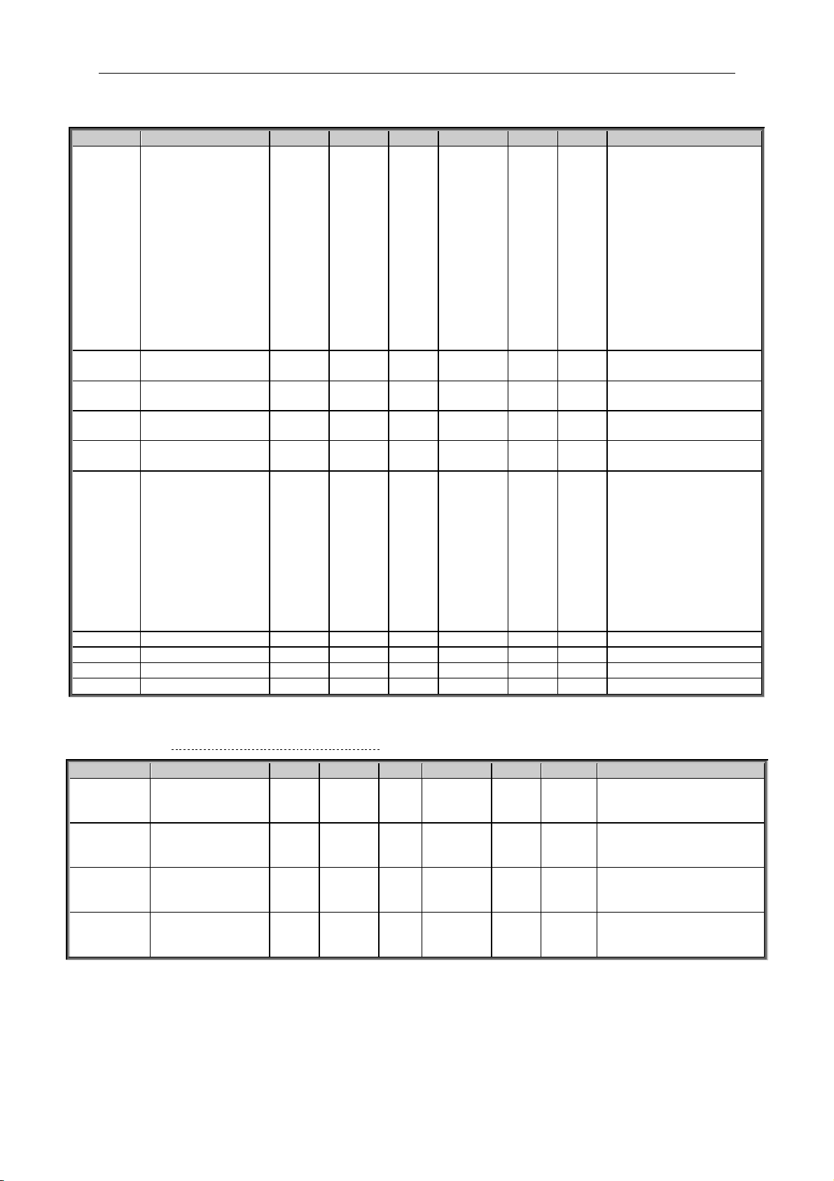
34 • VACON® apfiff41 Advance HS
Local contacts: http://drives.danfoss.com/danfoss-drives/local-contacts/
7.2.3 Torque Reference
Code
Parameter
Min
Max
Unit
Default
Cust
ID
Note
P2.2.9.1
Torque reference
selection
0 8
0
641
0=Not used
1=AI1
2=AI2
3=AI3
4=AI4
5=AI1 joystick (-10 – 10
V)
6=AI2 joystick (-10 – 10
V)
7=Torque reference from
keypad, R3.5
8=FB Torque Reference
9=Master Torque
10=Power Reference
P2.2.9.2
Torque reference
max.
–300,0
300,0 % 100
642
P2.2.9.3
Torque reference
min.
–300,0
300,0 % 0,0
643
P2.2.9.4
Torque reference
filtering time
0
32000
ms
0
1244
P2.2.9.5
Torque Reference
Dead Zone
0,0
300,0 % 0,00
1246
P2.2.9.6
Torque Select
0 5
2
1278
0 = Speed control
1 = Pos/neg freq limits
2 = RampOut (-/+)
3 = NegFreqLimit-
RampOut
4 = RampOutPosFreqLimit
5 = RampOut Window
6 = 0-RampOut
7 = RampOut Window
On/Off
P2.2.9.7
Window negative
0,00
50,00
Hz
2,00
1305
P2.2.9.8
Window positive
0,00
50,00
Hz
2,00
1304
P2.2.9.9
Window negative off
0,00
P2.10.11
Hz
0,00
1307
P2.2.9.10
Window positive off
0,00
P2.10.12
Hz
0,00
1306
7.2.3.1 Torque Reference OL Settings
Code
Parameter
Min
Max
Unit
Default
Cust
ID
Note
P2.2.9.11.1
Open loop torque
control minimum
frequency
0,00
50,00
Hz
3,00
636
P2.2.9.11.2
Open loop torque
controller
P gain
0
32000 150
639
P2.2.9.11.3
Open loop torque
controller
I gain
0
32000 10 640
P2.2.9.11.4
Torque speed limit
for Open Loop
0 2
1 644
0=Max. frequency
1=Selected frequency ref.
2=Preset speed 7
Page 35
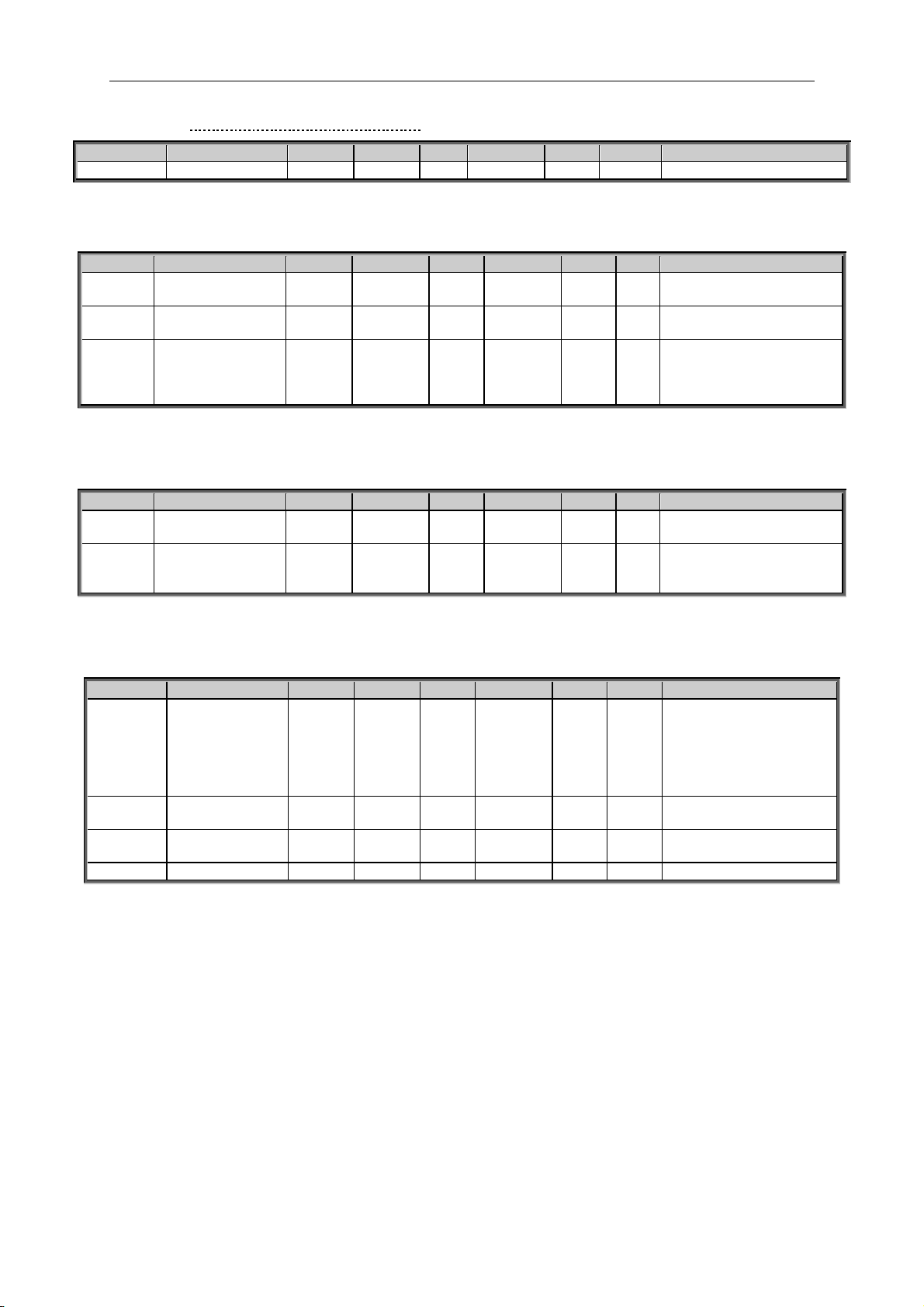
apfiff41 advanced high speed VACON® • 35
Local contacts: http://drives.danfoss.com/danfoss-drives/local-contacts/
Classified as Public
7.2.3.2 Torque Reference CL Settings
Code
Parameter
Min
Max
Unit
Default
Cust
ID
Note
P2.2.9.12.1
Torque Step
-300,0
300,0 % 0,0
1253
7.2.4 Prohibit frequency parameters
Code
Parameter
Min
Max
Unit
Default
Cust
ID
Note
P2.2.10.
1
Prohibit frequency
range 1 low limit
-1,00
320,00
Hz
0,00
509
0=Not used
P2.2.10.
2
Prohibit frequency
range 1 high limit
0,00
320,00
Hz
0,00
510
0=Not used
P2.2.10.
3
Ramp time factor
0,1
10,0 x 1,0
518
Multiplier of the currently
Selected ramp time
between prohibit
frequency limits.
Table 7-2. Prohibit frequencies (G2.5)
7.2.5 Motor Potentiometer
Code
Parameter
Min
Max
Unit
Default
Cust
ID
Note
P2.2.11.
1
Motor potentiometer
ramp rate
0,10
2000,00
Hz/s
1,00
331
Ramp rate for motor
potentio meter
P2.2.11.
2
Motor potentiometer
frequency reference
memory reset
0 2 1
367
0=No reset
1=Reset in stop state
2=Reset in powered down
Table 7-3. Motor potentiomer (G2.5)
7.2.6 Adjust Reference
Code
Parameter
Min
Max
Unit
Default
Cust
ID
Note
P2.2.12.1
Adjust input
0 5 0
493
0=Not used
1=AI1
2=AI2
3=AI3
4=AI4
5=Fieldbus
P2.2.12.2
Adjust minimum
0,0
100,0 % 0,0
494
Adjust limit to decrease
ref.
P2.2.12.3
Adjust maximum
0,0
100,0 % 0,0
495
Adjust limit to increase
ref.
P2.2.12.4
Speed Step
-200,0
200,0 % 1252
Page 36
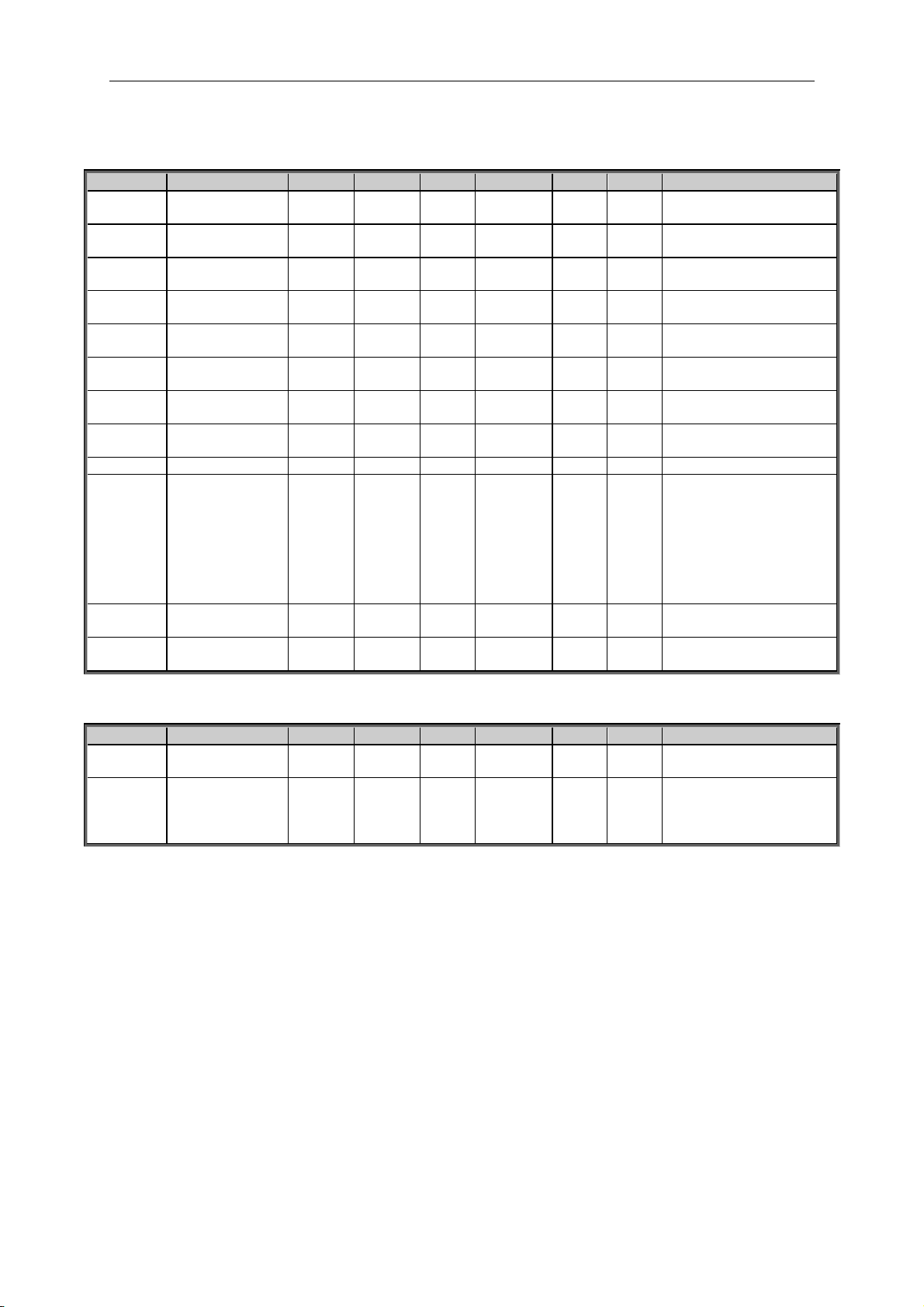
36 • VACON® apfiff41 Advance HS
Local contacts: http://drives.danfoss.com/danfoss-drives/local-contacts/
7.3 Ramp Control
7.3.1 Basic Settings
Code
Parameter
Min
Max
Unit
Default
Cust
ID
Note
P2.3.1
Start function
0 1
0
505
0=Ramp
1=Flying start
P2.3.2
Stop function
0 1
0
506
0=Coasting
1=Ramp
P2.3.3
Acceleration time
1
0,2
3270,0 s 3,0
103
0 Hz to Max frequency
P2.3.4
Deceleration time
1
0,2
3270,0 s 3,0
104
Max frequency to 0 Hz
P2.3.5
Ramp 1 shape
0
100 % 2
500
0=Linear
>0=S-curve ramp time
P2.3.6
Acceleration time
2
0,2
3270,0
s
10,0
502
P2.3.7
Deceleration time
2
0,2
3270,0
s
10,0
503 P2.3.8
Ramp 2 shape
0
100 % 4
501
0=Linear
>0=S-curve ramp time
P2.3.9
Inching Ramp
0,01
320,00
s
1,00
1257
P2.3.10
Reducing of
acc./dec. times
0 5
0
401
Scales active ramp from
100 % to 10 %.
0=Not used
1=AI1
2=AI2
3=AI3
4=AI4
5=Fieldbus
P2.3.11
IO Quick Stop
Mode
0 1
0
1276
0=Coasting
1= Ramp
P2.3.12
Quick Stop Ramp
time
0,1
3200,0
s
10,0
1256
7.3.2 Ramp Control Options
Code
Parameter
Min
Max
Unit
Default
Cust
ID
Note
P2.3.12.1
Ramp Input
Interpolator TC
0
200
ms
10
1184
P2.3.12.2
Ramp Time
Format
0 3
2
1500
0= #
1= #,#
2= #,##
3= #,###
Page 37

apfiff41 advanced high speed VACON® • 37
Local contacts: http://drives.danfoss.com/danfoss-drives/local-contacts/
Classified as Public
7.4 Input Signals
7.4.1 Basic Settings
Code
Parameter
Min
Max
Unit
Default
Cust
ID
Note
P2.4.1.1
Start/Stop logic
selection
0 7 0
300
Start
signal 1
(Default:
DIN1)
Start
signal 2
(Default:
DIN2)
0
1
2
3
4
5
6
7
Start fwd
Start/Stop
Start/Stop
Start pulse
Start
Start fwd*
Start*/Stop
Start*/Stop
Start rvs
Reverse
Run enable
Stop pulse
Mot.Pot UP
Start rvs*
Reverse
Run Enable
Table 7-4. Input signals: basic settings, G2.2.1
* = Rising edge required to start
Page 38

38 • VACON® apfiff41 Advance HS
Local contacts: http://drives.danfoss.com/danfoss-drives/local-contacts/
7.4.2 Digital inputs
Code
Parameter
Min
Default
Cust
ID
Note
P2.4.2.1
Start signal 1
0.1
A.1 403
Forward, See ID300
P2.4.2.2
Start signal 2
0.1
A.2 404
Reverse. See ID300
P2.4.2.3
Run enable
0.1
0.2 407
Motor start enabled (cc)
P2.4.2.4
Reverse
0.1
0.1 412
Direction forward (oc)
Direction reverse (cc)
P2.4.2.5
Preset speed 1
0.1
0.1 419
See preset speeds in basing
parameter group G2.1
P2.4.2.6
Preset speed 2
0.1
0.1 420 P2.4.2.7
Preset speed 3
0.1
0.1 421
P2.4.2.8
Motor potentiometer
reference DOWN
0.1
0.1 417
Mot.pot. reference decreases (cc)
P2.4.2.9
Motor potentiometer
reference UP
0.1
0.1 418
Mot.pot. reference increases (cc)
P2.4.2.10
Fault reset
0.1
0.1 414
All faults reset (cc)
P2.4.2.11
External fault (close)
0.1
0.1 405
Ext. fault displayed (cc)
P2.4.2.12
External fault (open)
0.1
0.2 406
Ext. fault displayed (oc)
P2.4.2.13
Acc/Dec time selection
0.1
0.1 408
Acc/Dec time 1 (oc)
Acc/Dec time 2 (cc)
P2.4.2.14
Acc/Dec prohibit
0.1
0.1 415
Acc/Dec prohibited (cc)
P2.4.2.15
DC braking
0.1
0.1 416
DC braking active (cc)
P2.4.2.16
Jogging speed
0.1
0.1 413
Jogging speed selected for
frequency reference (cc)
P2.4.2.17
IO reference 1 / 2 selection
0.1
0.1 422
IO reference selection:14 ID117
P2.4.2.18
Control from I/O terminal
0.1
0.1 409
Force control place to I/O terminal
(cc)
P2.4.2.19
Control from keypad
0.1
0.1 410
Force control place to keypad (cc)
P2.4.2.20
Control from fieldbus
0.1
0.1 411
Force control place to fieldbus (cc)
P2.4.2.21
Parameter set 1/set 2
selection
0.1
0.1 496
Closed cont.=Set 2 is used
Open cont.=Set 1 is used
P2.4.2.22
Motor control mode 1/2
0.1
0.1 164
Closed cont.=Mode 2 is used
Open cont.=Mode 1 is used
See par 2.6.1, 2.6.12
P2.4.2.23
External Brake
Acknowledge
0.1
0.2 1210
Monitoring signal from mechanical
brake
P2.4.2.24
Cooling Monitor
0.1
0.2 750
Used when water cooled unit
P2.4.2.25
Enable Inching
0.1
0.1 532
Enables Inching function
P2.4.2.26
Inching 1
0.1
0.1 531
Inching reference 1 (Default
Forward 2 Hz. See P2.4.16). This
will start the drive.
P2.4.2.27
Inching 2
0.1
0.1 532
Inching reference 2 (Default
Reverse -2 Hz. See P2.4.17).
This will start the drive.
P2.4.2.28
Reset Position
0.1
0.1 1090
P2.4.2.29
MF Mode 2
0.1
0.1 1092
P2.4.2.30
Quick Stop
0.1
0.2 1213
P2.4.2.31
Input Switch Ack
0.1
0.1 1209
P2.4.2.32
PID Activation
0.1
0.1 1804
Table 7-5. Digital input signals, G2.2.4
cc = closing contact
oc = opening contact
Page 39

apfiff41 advanced high speed VACON® • 39
Local contacts: http://drives.danfoss.com/danfoss-drives/local-contacts/
Classified as Public
7.4.3 Analogue input 1
Code
Parameter
Min
Max
Unit
Default
Cust
ID
Note
P2.4.3.1
AI1 signal selection
0.1
E.10 A.1
377
Slot . Board input No.
P2.4.3.2
AI1 filter time
0,000
32,000
s
0,000
324
0=No filtering
P2.4.3.3
AI1 signal range
0 3
0
320
0=0…100%*
1=20…100%* 4 mA Fault
2= -10V…+10V*
3= Custom range*
P2.4.3.4
AI1 custom minimum
setting
-160,00
160,00
%
0,00
321
Custom Range:
Minimum input
P2.4.3.5
AI1 custom
maximum setting
-160,00
160,00
%
100,00
322
Custom Range:
Maximum input
P2.4.3.6
AI1 reference
scaling, minimum
value
0,00
320,00
Hz
0,00
303
Selects the frequency that
corresponds to the min.
reference signal
P2.4.3.7
AI1 reference
scaling, maximum
value
0,00
320,00
Hz
0,00
304
Selects the frequency that
corresponds to the max.
reference signal
P2.4.3.8
AI1 joystick Dead
Zone
0,00
20,00
%
0,00
384
Dead Zone for joystick
input
P2.4.3.9
AI1 sleep limit
0,00
100,00
%
0,00
385
Drive goest to stop if input
is below this limit for this
time.
P2.4.3.10
AI1 sleep delay
0,00
320,00
s
0,00
386
P2.4.3.11
AI1 joystick offset
-100,00
100,00
%
0,00
165
Press enter for 1s to set
offset
Table 7-6. Analogue input 1 parameters, G2.2.2
7.4.4 Analogue input 2
Code
Parameter
Min
Max
Unit
Default
Cust
ID
Note
P2.4.4.1
AI2 signal selection
0.1
E.10 A.2
388
Slot . Board input No.
P2.4.4.2
AI2 filter time
0,000
32,000
s
0,000
329
0=No filtering
P2.4.4.3
AI2 signal range
0 3
1
325
0=0…100%*
1=20…100%* 4 mA Fault
2= -10V…+10V*
3= Custom range*
P2.4.4.4
AI2 custom minimum
setting
-160,00
160,00
%
0,00
326
Custom Range:
Minimum input
P2.4.4.5
AI2 custom
maximum setting
-160,00
160,00
%
100,00
327
Custom Range:
Maximum input
P2.4.4.6
AI2 reference
scaling, minimum
value
0,00
320,00
Hz
0,00
393
Selects the frequency that
corresponds to the min.
reference signal
P2.4.4.7
AI2 reference
scaling, maximum
value
0,00
320,00
Hz
0,00
394
Selects the frequency that
corresponds to the max.
reference signal
P2.4.4.8
AI2 joystick Dead
Zone
0,00
20,00
%
0,00
395
Dead Zone for joystick
input
P2.4.4.9
AI2 sleep limit
0,00
100,00
%
0,00
396
Drive goes to stop if input
is below this limit for this
time.
P2.4.4.10
AI2 sleep delay
0,00
320,00
s
0,00
397
P2.4.4.11
AI2 joystick offset
-100,00
100,00
%
0,00
166
Press enter for 1s to set
offset
Table 7-7. Analogue input 2 parameters, G2.2.3
*Remember to place jumpers of block X2 accordingly.
See NX User's Manual, chapter 6.2.2.2
Page 40
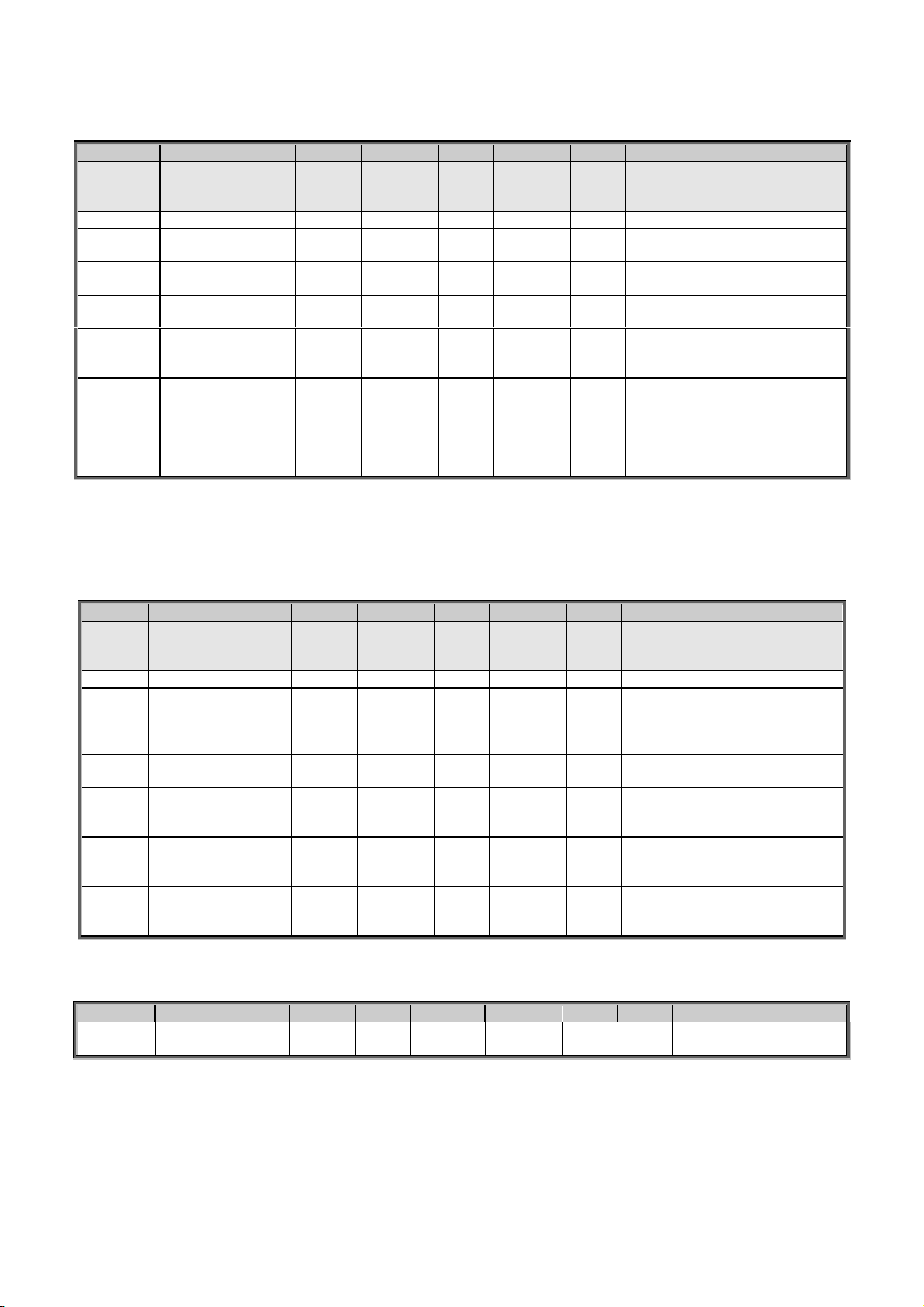
40 • VACON® apfiff41 Advance HS
Local contacts: http://drives.danfoss.com/danfoss-drives/local-contacts/
7.4.5 Analogue input 3
Code
Parameter
Min
Max
Unit
Default
Cust
ID
Note
P2.4.5.1
AI3 signal selection
0.1
E.10 0.1
141
Slot . Board input No.
If 0.1 ID27 can be
controlled from FB
P2.4.5.2
AI3 filter time
0,000
32,000
s
0,000
142
0=No filtering
P2.4.5.3
AI3 custom minimum
setting
-160,00
160,00
%
0,00
144
Custom range always
active. See ID326
P2.4.5.4
AI3 custom
maximum setting
-160,00
160,00
%
100,00
145
Custom range always
active. See ID327
P2.4.5.5
AI3 signal inversion
0 1
0
151
0=Not inverted
1=Inverted
P2.4.5.6
AI3 reference
scaling, minimum
value
-32000
32000 0
1037
Selects the value that
corresponds to the min.
reference signal
P2.4.5.7
AI3 reference
scaling, maximum
value
-32000
32000 0
1038
Selects the value that
corresponds to the max.
reference signal
P2.4.5.8
AI3 Controlled ID
0
10000 0
1509
Select parameter that
you want to control by ID
number.
Table 7-8. Analogue input 3 parameters, G2.2.4
7.4.6 Analogue input 4
Code
Parameter
Min
Max
Unit
Default
Cust
ID
Note
P2.4.6.1
AI4 signal selection
0.1
E.10 0.1
152
Slot . Board input No.
If 0.1 ID28 can be
controlled from FB
P2.4.6.2
AI4 filter time
0,000
32,000
s
0,000
153
0=No filtering
P2.4.6.3
AI4 custom minimum
setting
-160,00
160,00
%
0,00
155
Custom range always
active. See ID326
P2.4.6.4
AI4 custom maximum
setting
-160,00
160,00
%
100,00
156
Custom range always
active. See ID327
P2.4.6.5
AI4 signal inversion
0 1
0
162
0=Not inverted
1=Inverted
P2.4.6.6
AI3 reference scaling,
minimum value
-32000
-32000 0
1039
Selects the value that
corresponds to the min.
reference signal
P2.4.6.7
AI3 reference scaling,
maximum value
-32000
32000 0
1040
Selects the value that
corresponds to the max.
reference signal
P2.4.6.8
AI4 Controlled ID
0
10000 0
1510
Select parameter that
you want to control by
ID number.
Table 7-9. Analogue input 4 parameters, G2.2.5
7.4.7 Options
Code
Parameter
Min
Max
Unit
Default
Cust
ID
Note
P2.4.7.1
Input signal inversion
Control
0
6553
5
0
1091
**Remember to place jumpers of block X2 accordingly.
See NX User's Manual, chapter 6.2.2.2
Page 41

apfiff41 advanced high speed VACON® • 41
Local contacts: http://drives.danfoss.com/danfoss-drives/local-contacts/
Classified as Public
7.5 Output Signals
7.5.1 Digital output signals
Code
Parameter
Min
Default
Cust
ID
Note
P2.5.1.1
Ready
0.1
0.1
432
Ready to Run
P2.5.1.2
Run
0.1
0.1
433
Running
P2.5.1.3
Fault
0.1
0.1
434
Drive in fault state
P2.5.1.4
Inverted fault
0.1
0.1
435
Drive not in fault state
P2.5.1.5
Warning
0.1
0.1
436
Warning active
P2.5.1.6
External fault
0.1
0.1
437
External fault active
P2.5.1.7
Reference fault/warning
0.1
0.1
438
4 mA fault active
P2.5.1.8
Over temperature
warning
0.1
0.1
439
Drive over temperature
active
P2.5.1.9
Reverse
0.1
0.1
440
Output frequency < 0 Hz
P2.5.1.1
0
Unrequested direction
0.1
0.1
441
Reference <> Output
frequency
P2.5.1.1
1
At speed
0.1
0.1
442
Reference = Output
frequency
P2.5.1.1
2
Jogging speed
0.1
0.1
443
Jogging or preset speed
command active
P2.5.1.1
3
External control place
0.1
0.1
444
IO control active
P2.5.1.1
4
External brake control
0.1
0.1
445
See explanations on
chapter Brake Control
P2.5.1.1
5
External brake control,
inverted
0.1
0.1
446
P2.5.1.1
6
Output frequency limit 1
supervision
0.1
0.1
447
See ID315
P2.5.1.1
7
Output frequency limit 2
supervision
0.1
0.1
448
See ID346
P2.5.1.1
8
Reference limit supervision
0.1
0.1
449
See ID350
P2.5.1.1
9
Temperature limit
supervision
0.1
0.1
450
Drive temperature
supervision. See ID354
P2.5.1.2
0
Torque limit supervision
0.1
0.1
451
See ID348
P2.5.1.2
1
Motor thermal protection
0.1
0.1
452
Thermistor fault or warning
P2.5.1.22 Analogue input
supervision limit
0.1
0.1
463
See ID356
P2.5.1.23 Motor regulator
activation
0.1
0.1
454
One of limit controller is
active
P2.5.1.2
4
Fieldbus digital input 1
0.1
0.1
455
FB CW B11
P2.5.1.2
5
FB Dig 1 Parameter
ID0
ID0
891
Select parameter to control
P2.5.1.2
6
Fieldbus digital input 2
0.1
0.1
456
FB CW B12
P2.5.1.2
7
FB Dig 2 Parameter
ID0
ID0
892
Select parameter to control
P2.5.1.2
8
Fieldbus digital input 3
0.1
0.1
457
FB CW B13
P2.5.1.2
9
FB Dig 3 Parameter
ID0
ID0
893
Select parameter to control
P2.5.1.3
0
Fieldbus digital input 4
0.1
0.1
169
FB CW B14
P2.5.1.3
1
FB Dig 4 Parameter
ID0
ID0
894
Select parameter to control
P2.5.1.3
2
Fieldbus digital input 5
0.1
0.1
170
FB CW B15
P2.5.1.3
3
FB Dig 5 Parameter
ID0
ID0
895
Select parameter to control
Page 42

42 • VACON® apfiff41 Advance HS
Local contacts: http://drives.danfoss.com/danfoss-drives/local-contacts/
P2.5.1.3
4
Safe Disable Active
0.1
0.1
756
P2.5.1.3
5
MCC Close Continuous
0.1
0.1
1218
P2.5.1.3
6
MCC Close Pulse
0.1
0.1
1219
7.5.2 Analogue output 1
Code
Parameter
Min
Max
Unit
Default
Cust
ID
Note
P2.5.2.1
Analogue output 1
signal selection
0.1
E.10 A.1
464
TTF programming
See chapter 3.1 and 3.2
P2.5.2.2
Analogue output 1
function
0
20 1
307
0=Not used (4 mA / 2 V)
1=Output freq. (0—f
max
)
2=Freq. reference (0—
f
max
)
3=Motor speed (0—Motor
nominal speed)
4=Motor current (0—
I
nMotor
)
5=Motor torque (0—
T
nMotor
)
6=Motor power (0—
P
nMotor
)
7=Motor voltage (0-U
nMotor
)
8=DC-link volt (0—1000V)
9=AI1
10=AI2
11=Output freq. (f
min
- f
max
)
12=-
2xTorque…+2xTorqu
e
13=-2xPower…+2xPower
14=PT100 temperature
15=FB Analog Output
16= -2xSpeed…+2xSpeed
17= Encoder speed (0—
Motor nominal speed)
18=Final Freq.Ref
19= Value Control Out
20=Drive Output Power
P2.5.2.3
Analogue output 1
filter time
0,00
10,00
s
1,00
308
0=No filtering
P2.5.2.4
Analogue output 1
inversion
0 1 0
309
0=Not inverted
1=Inverted
P2.5.2.5
Analogue output 1
minimum
0 1 0
310
0=0 mA (0 %)
1=4 mA (20 %)
P2.5.2.6
Analogue output 1
scale
10
1000
%
100
311
P2.5.2.7
Analogue output 1
offset
-100,00
100,00
%
0,00
375
Table 7-10. Analogue output 1 parameters, G2.3.5
Page 43

apfiff41 advanced high speed VACON® • 43
Local contacts: http://drives.danfoss.com/danfoss-drives/local-contacts/
Classified as Public
7.5.3 Analogue output 2
Code
Parameter
Min
Max
Unit
Default
Cust
ID
Note
P2.5.3.1
Analogue output 2
signal selection
0.1
E.10 0.1
471
TTF programming
See chapter 3.1 and 3.2
P2.5.3.2
Analogue output 2
function
0
20 4
472
See P2.5.2.2
P2.5.3.3
Analogue output 2
filter time
0,00
10,00
s
1,00
473
0=No filtering
P2.5.3.4
Analogue output 2
inversion
0 1 0
474
0=Not inverted
1=Inverted
P2.5.3.5
Analogue output 2
minimum
0 1 0
475
0=0 mA (0 %)
1=4 mA (20 %)
P2.5.3.6
Analogue output 2
scale
10
1000
%
100
476 P2.5.3.7
Analogue output 2
offset
-100,00
100,00
%
0,00
477
Table 7-11. Analogue output 2 parameters, G2.3.6
7.5.4 Analogue output 3
Code
Parameter
Min
Max
Unit
Default
Cust
ID
Note
P2.5.4.1
Analogue output 3
signal selection
0.1
E.10 0.1
478
TTF programming
See chapter 3.1 and 3.2
P2.5.4.2
Analogue output 3
function
0
20 5
479
See P2.5.2.2
P2.5.4.3
Analogue output 3
filter time
0,00
10,00
s
1,00
480
0=No filtering
P2.5.4.4
Analogue output 3
inversion
0 1 0
481
0=Not inverted
1=Inverted
P2.5.4.5
Analogue output 3
minimum
0 1 0
482
0=0 mA (0 %)
1=4 mA (20 %)
P2.5.4.6
Analogue output 3
scale
10
1000
%
100
483
P2.5.4.7
Analogue output 3
offset
-100,00
100,00
%
0,00
484
Table 7-12. Analogue output 3 parameters, G2.3.7
Page 44

44 • VACON® apfiff41 Advance HS
Local contacts: http://drives.danfoss.com/danfoss-drives/local-contacts/
7.5.5 Delayed digital output 1
Code
Parameter
Min
Max
Unit
Default
Cust
ID
Note
P2.5.5.1
Digital output 1
signal selection
0.1
E.10 0.1
486
Posibility to invert by
ID1091 INV Commands
P2.5.5.2
Digital output 1
function
0
26 1
312
0=Not used
1=Ready
2=Run
3=Fault
4=Fault inverted
5=FC overheat warning
6=Ext. fault or warning
7=Ref. fault or warning
8=Warning
9=Reverse
10=Jogging spd selected
11=At speed
12=Mot. regulator active
13=Freq. limit 1 superv.
14=Freq. limit 2 superv.
15=Torque limit superv.
16=Ref. limit supervision
17=External brake control
18=I/O control place act.
19=FC temp. limit superv.
20=Reference inverted
21=Ext. brake control
inverted
22=Therm. fault or warn.
23=On/Off control
24=Fieldbus input data 1
25=Fieldbus input data 2
26=Fieldbus input data 3
P2.5.5.3
Digital output 1 on
delay
0,00
320,00
s
0,00
487
0,00 = On delay not in
use
P2.5.5.4
Digital output 1 off
delay
0,00
320,00
s
0.00
488
0,00 = Off delay not in
use
P2.5.5.5
Invert delayed DO1
0 1 0
1587
0=Not inverted
1=Inverted
Table 7-13. Delayed digital output 1 parameters, G2.3.1
7.5.6 Delayed digital output 2
Code
Parameter
Min
Max
Unit
Default
Cust
ID
Note
P2.5.6.1
Digital output 2
signal selection
0.1
E.10 0.1
489
Possibility to invert by
ID1091 INV Commands
P2.5.6.2
Digital output 2
function
0
28 0
490
See P2.5.6.2
P2.5.6.3
Digital output 2 on
delay
0,00
320,00
s
0,00
491
0,00 = On delay not in
use
P2.5.6.4
Digital output 2 off
delay
0,00
320,00
s
0,00
492
0,00 = Off delay not in
use
P2.5.6.5
Invert delayed DO2
0 1 0
1588
0=Not inverted
1=Inverted
Table 7-14. Delayed digital output 2 parameters, G2.3.2
Page 45

apfiff41 advanced high speed VACON® • 45
Local contacts: http://drives.danfoss.com/danfoss-drives/local-contacts/
Classified as Public
7.5.7 Supervision Limits
Code
Parameter
Min
Max
Unit
Default
Cust
ID
Note
P2.5.7.1
Output frequency
limit 1 supervision
0 2 0
315
0=No limit
1=Low limit supervision
2=High limit supervision
P2.5.7.2
Output frequency
limit 1;
Supervised value
0,00
320,00
Hz
0,00
316 P2.5.7.3
Output frequency
limit 2 supervision
0 2 0
346
0=No limit
1=Low limit supervision
2=High limit supervision
P2.5.7.4
Output frequency
limit 2;
Supervised value
0,00
320,00
Hz
0,00
347
P2.5.7.5
Torque limit
supervision
0 2 0
348
0=Not used
1=Low limit supervision
2=High limit supervision
P2.5.7.6
Torque limit
supervision value
-300,0
300,0
%
100,0
349 P2.5.7.7
Reducing of torque
supervision limit
0 5
0
402
P2.5.7.8
Reference limit
supervision
0 2 0
350
0=Not used
1=Low limit
2=High limit
P2.5.7.9
Reference limit
supervision value
0,00
100,0
%
0,00
351
P2.5.7.10
FC temperature
supervision
0 2 0
354
0=Not used
1=Low limit
2=High limit
P2.5.7.11
FC temperature
supervised value
–10
100
C
40
355
P2.5.7.12
Analogue
supervision signal
0
4 0
356
0=Not used
1=AI1
2=AI2
3=AI3
4=AI4
P2.5.7.13
Analogue
supervision low limit
0,00
100,00
%
10,00
357
Reset limit
P2.5.7.14
Analogue
supervision high
limit
0,00
100,00
%
90,00
358
Set limit
Table 7-15. Supervision Limit settings, G2.3.4
7.6 Limit Settings
7.6.1 Current handling
Code
Parameter
Min
Max
Unit
Default
Cust
ID
Note
P2.6.1.1
Current limit
0
2 x IH A IL
107
Reaching the limit will lower
output frequency
P2.6.1.2
Scaling of current
limit
0 5
0
399
Scaling from 0 to ID107
0=Not used
1=AI1
2=AI2
3=AI3
4=AI4
5=FB Limit Scaling ID46
P2.6.1.3
Over Current Kp
0
32000
20000
1761
P2.6.1.4
Over Current ki
0
32000 400
1762
Page 46

46 • VACON® apfiff41 Advance HS
Local contacts: http://drives.danfoss.com/danfoss-drives/local-contacts/
7.6.2 Power Handling
Code
Parameter
Min
Max
Unit
Default
Cust
ID
Note
P2.6.2.1
Generator Power Limit
0,0
300,0 % 300,0
1290
P2.6.2.2
Motoring Power Limit
0,0
300,0 % 300,0
1289
P2.6.2.3
Scaling Motoring
Power Limit
0 5
0
179
As parameter P2.6.2
Scaling from 0 to ID1289
P2.6.2.4
Scaling Generator
Power Limit
0 5
0
1088
As parameter P2.6.2
Scaling from 0 to ID1290
Page 47

apfiff41 advanced high speed VACON® • 47
Local contacts: http://drives.danfoss.com/danfoss-drives/local-contacts/
Classified as Public
7.6.3 Torque Handling
Code
Parameter
Min
Max
Unit
Default
Cust
ID
Note
P2.6.3.1
Motoring Torque Limit
0,0
300,0
%
300,0
1287
Motoring side torque limit
P2.6.3.2
Generator Torque
Limit
0,0
300,0
%
300,0
1288
Generator side torque limit
P2.6.3.3
Scaling Motoring
Torque limit
0 5
0
485
Scaling from 0 to ID1287
0=Not used
1=AI1
2=AI2
3=AI3
4=AI4
5=FB Limit Scaling ID46
P2.6.3.4
Scaling Generator
Torque limit
0 5
0
1087
Scaling from 0 to ID1288
As parameter P2.6.3.9
7.6.3.1 Torque Handling OL Settings
Code
Parameter
Min
Max
Unit
Default
Cust
ID
Note
P2.6.3.5.
1
Torque limit control
P-gain
0,0
32000
3000
610
P2.6.3.5.
2
Torque limit control
I-gain
0,0
32000 200
611
7.6.3.2 Torque Handling CL Settings
Code
Parameter
Min
Max
Unit
Default
Cust
ID
Note
P2.6.3.6.1
SPC Out Limit
0,0
300,0
%
300,0
1382
P2.6.3.6.2
SPC Pos Limit
0,0
300,0
%
300,0
646
P2.6.3.6.3
SPC Neg Limit
0,0
300,0
%
300,0
645
7.6.4 Frequency Handling
Code
Parameter
Min
Max
Unit
Default
Cust
ID
Note
P2.6.4.1
Negative frequency
limit
-320,00
320,00
Hz
-320,00
1286
Alternative limit for negative
direction
P2.6.4.2
Positive frequency
limit
-320,00
320,00
Hz
320,00
1285
Alternative limit for positive
direction
P2.6.4.3
Zero Frequency limit
0,00
320,00
Hz
1,00
1283
Page 48

48 • VACON® apfiff41 Advance HS
Local contacts: http://drives.danfoss.com/danfoss-drives/local-contacts/
7.6.5 DC-Link Handling
Code
Parameter
Min
Max
Unit
Default
Cust
ID
Note
P2.6.5.1
Overvoltage controller
0 2
1
607
0=Not used
1=Used (no ramping)
2=Used (ramping)
P2.6.5.2
Over Voltage
Reference selector
0 2
1
1262
0=High Voltage
1=Normal Voltage
2=BrakeChopperLevel
P2.6.5.3
Brake chopper
0 4
0
504
0=Disabled
1=Used when running
2=External brake chopper
3=Used when
stopped/running
4=Used when running (no
testing)
P2.6.5.4
Brake Chopper Level
0
1267
V
Varies
1267
500 V unit: 567 Vdc
6690 V unit: 836 Vdc
P2.6.5.5
Undervoltage
controller
0 2
1
608
0=Not used
1=Used (no ramping)
2=Used (ramping to zero)
P2.6.5.6
Under Voltage Kp
1415
P2.6.5.7
Under Voltage Ki
1416
P2.6.5.8
Under Voltage Kd
1265
P2.6.5.9
UV Control Threshold
100
1000 V 1711
7.6.5.1 DC-Link Handling CL Settings
Code
Parameter
Min
Max
Unit
Default
Cust
ID
Note
P2.6.5.10.1
Over voltage
reference
94.00
130.0
0
%
118.00
1528
P2.6.5.10.2
Over voltage
motoring side torque
limit
0.0
300.0 % 10.0
1623
Maximum motoring torque
when over voltage controller
is active.
P2.6.5.10.3
CL Under Voltage
Reference
60.00
80.00 % 65.00
1567
Table 7-16. DC-link handling closed loop parameters, G2.6.5.8
Page 49
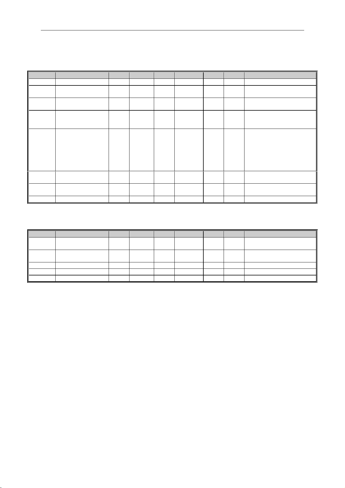
apfiff41 advanced high speed VACON® • 49
Local contacts: http://drives.danfoss.com/danfoss-drives/local-contacts/
Classified as Public
7.7 Flux and DC Current handling
7.7.1 Flux and DC Current handling OL Settings
Code
Parameter
Min
Max
Unit
Default
Cust
ID
Note
P2.7.1.1
DC braking current
0,00
IL A 0,00
507
P2.7.1.2
DC braking time
at start
0,00
600,00
s
0,00
516
0=DC brake is off at start
P2.7.1.3
DC braking time
at stop
0,00
600,00
s
0,00
508
0=DC brake is off at stop
P2.7.1.4
Frequency to start DC
braking during
ramp stop
0,10
10,00
Hz
1,50
515
P2.7.1.5
Scaling of DC-braking
current
0 5
0
400
ID46Scaling from 0 to ID507
0=Not used
1=AI1
2=AI2
3=AI3
4=AI4
5=FB Limit Scaling
P2.7.1.6
DC-Brake Current in
Stop
0,00
IL A Varies
1080
P2.7.1.7
Flux brake
0 1
0
520
0=Off
1=On
P2.7.1.8
Flux braking current
0,00
IL A IH
519
7.7.2 Flux and DC Current handling CL Settings
Code
Parameter
Min
Max
Unit
Default
Cust
ID
Note
P2.7.2.1
Magnetizing current at
start
0
IL A 0,00
627
P2.7.2.2
Magnetizing time at
start
0,0
600,0 s 0,0
628
P2.7.2.3
Flux Reference
0,0
500,0
%
100,0
1250
P2.7.2.4
Flux Off Delay
-1
32000 s 0
1402
-1=forever
P2.7.2.5
Stop State Flux
0,0
150,0
%
100,0
1401
Page 50
50 • VACON® apfiff41 Advance HS
Local contacts: http://drives.danfoss.com/danfoss-drives/local-contacts/
7.8 Motor Control
7.8.1 Motor Control Basic Settings
Code
Parameter
Min
Max
Unit
Default
Cust
ID
Note
P2.8.1
Motor control mode
0 4
0
600
0=Frequency control
1=Speed control
2= Torque control
3=Closed loop speed ctrl
4=Closed loop
Speed/torque ctrl
P2.8.2
Motor control
mode 2
0 4
2
521
See P2.8.1
7.8.2 U/f Settings
Code
Parameter
Min
Max
Unit
Default
Cust
ID
Note
P2.8.3.1
U/f optimisation
0 1
0
109
0=Not used
1=Automatic torque boost
P2.8.3.2
U/f ratio selection
0 3
0
108
0=Linear
1=Squared
2=Programmable
3=Linear with flux optim.
P2.8.3.3
Field weakening point
6,00
320,00
Hz
50,00
602
P2.8.3.4
Voltage at field
weakening point
10,00 200,00
%
100,00
603
n% x U
nmot
P2.8.3.5
U/f curve midpoint
frequency
0,00
P2.8.3.3
Hz
50,00
604
P2.8.3.6
U/f curve midpoint
voltage
0,00
100,00
%
100,00
605
n% x U
nmot
Parameter max. value =
P2.6.5
P2.8.3.7
Output voltage at
zero frequency
0,00
40,00
%
0,00
606
n% x U
nmot
P2.8.3.8
OL Mode
0 3 0
1600
P2.8.3.9
I/f Start
0 1 1
1809
0=Disable
1=Enable
P2.8.3.10
I/f Current
0,0
150,0
%
50,0
1693
P2.8.3.11
I/f Control Limit
0,0
300,0
%
10,0
1790
7.8.3 Closed Loop Control Settings
Code
Parameter
Min
Max
Unit
Default
Cust
ID
Note
P2.8.4.1
Current control
P gain
0,00
100,00
%
15,00
617
P2.8.4.2
Current control
I Time
0,0
3200,0
ms
1,5
657
P2.8.4.3
Slip adjust
0
500 % 75
619
P2.8.4.4
Acceleration
compensation
0,00
300,00
s
0,00
626
P2.8.4.5
Speed Error Filter TC
0
1000
ms 0
1311
P2.8.4.6
Encoder filter time
0
1000
ms 0
618
P2.8.4.7
SC Torque Chain
Select
0
65535 0
1557
Default 96 after
identification.
Page 51

apfiff41 advanced high speed VACON® • 51
Local contacts: http://drives.danfoss.com/danfoss-drives/local-contacts/
Classified as Public
7.8.4 PMSM Control settings
Code
Parameter
Min
Max
Unit
Default
Cust
ID
Note
P2.8.5.1
PMSM Shaft
Position
0
65535 0
649
P2.8.5.2
Start Angle
Identification mode
0
10 0
169
1
0=Automatic
1=Forced
2=After Power Up
3=Disabled
P2.8.5.3
Start Angle
Identification ID
Current
0,0
150,0 % 0,0
175
6 P2.8.5.4
Polarity Pulse
Current
-10,0
200,0 % 0,0
156
6
P2.8.5.5
Start Angle ID
Time
0
32000
ms 0
175
5
P2.8.5.6
I/f Current
0,0
150,0
%
50,0
169
3
P2.8.5.7
I/f Control Limit
0,0
300,0
%
10,0
179
0
P2.8.5.8
Flux Current Kp
0
32000
5000
651
P2.8.5.9
Flux Current Ti
0
1000 25
652
P2.8.5.10
Enable Rs
Identification
0 1 0
654
0=No
1=Yes
P2.8.5.11
Lsd Voltage Drop
-32000
32000 0
175
7
P2.8.5.12
Lsq Voltage Drop
-32000
32000 0
175
8
P2.8.5.13
Cos Phii 1 Control
0 1 0
1759 0=No
1=Yes
P2.8.5.14
Optimize Current
0 1 0
1800 0=No
1=Yes
P2.8.5.15
Enable Start
Positioning
Damping
0 1 0
1788 0=No
1=Yes
P2.8.5.16
Encoder Speed
Adjust
0 1 0
1779 0=No
1=Yes
P2.8.5.17
Enable Flux
Stabilizer
0 1 0
1801 0=No
1=Yes
P2.8.5.18
Current Control Kp
d
0
32000
176
6
P2.8.5.19
Voltage Margin
0
1200
176
7
P2.8.5.20
ExtIdRef
-150
150 0,0
173
0
P2.8.5.21
Start Angle Offset
-360
360 0,0
696
Page 52

52 • VACON® apfiff41 Advance HS
Local contacts: http://drives.danfoss.com/danfoss-drives/local-contacts/
7.8.5 Stabilators
Code
Parameter
Min
Max
Unit
Default
Cust
ID
Note
P2.8.6.1
Torque Stabilator
Gain
0
1000 100
1412
P2.8.6.2
Torque Stabilator
Damping
0
1000 980
1413
With PMSM use 980
P2.8.6.3
Torque Stabilator
Gain in FWP
0
1000 50
1414
P2.8.6.4
Torque Stabilator
Limit
0
1500 150
1720
P2.8.6.5
Flux Circle Stabilator
Gain
0
32767
10000
1550
P2.8.6.6
Flux Circle Stabilator
TC
0
32700 900
1551
P2.8.6.7
Flux Stabilator Gain
0
32000 500
1797
P2.8.6.8
Flux Stab Coeff
-30000
30000 1796
P2.8.6.9
Voltage Stabilator
Gain
0
100,0 % 10,0
1738
P2.8.6.10
Voltage Stabilator TC
0
1000 900
1552
P2.8.6.11
Voltage Stabilator
Limit
0
320,00
Hz
1,50
1553
7.8.6 Tuning parameters
Code
Parameter
Min
Max
Unit
Default
Cust
ID
Note
P2.8.7.1
Fly Start Options
0
65535 0
1610
P2.8.7.2
Resonance Damping
Select
0
200 0,00
1760
P2.8.7.3
Damping Frequency
0
320,00
Hz 0
1763
P2.8.7.4
Damping Gain
0
32000 0
1764
P2.8.7.5
Damping Phase
0
360 0,00
1765
P2.8.8.6
Damping Activation
Frequency
0
320,00 % 0
1770
P2.8.7.7
Damping Filter Time
Constant
0
32700 105
1771
P2.8.7.8
Over Modulation
Limit
50
120 % 96
1515
P2.8.7.9
Modulator Index Limit
0
200 % 100
655
P2.8.7.10
Enable DC
Compensation
0 1 0
1732
P2.8.7.11
DC-Compensation
Gain
0
30000 10
1735
Page 53

apfiff41 advanced high speed VACON® • 53
Local contacts: http://drives.danfoss.com/danfoss-drives/local-contacts/
Classified as Public
7.8.7 Identification parameters
Code
Parameter
Min
Max
Unit
Default
Cust
ID
Note
P2.8.8.1
Flux 10 %
0
2500 % 10
135
5
P2.8.8.2
Flux 20 %
0
2500 % 20
135
6
P2.8.8.3
Flux 30 %
0
2500 % 30
135
7
P2.8.8.4
Flux 40 %
0
2500 % 40
135
8
P2.8.8.5
Flux 50 %
0
2500 % 50
135
9
P2.8.8.6
Flux 60 %
0
2500 % 60
136
0
P2.8.8.7
Flux 70 %
0
2500 % 70
136
1
P2.8.8.8
Flux 80 %
0
2500 % 80
136
2
P2.8.8.9
Flux 90 %
0
2500 % 90
136
3
P2.8.8.10
Flux 100 %
0
2500 % 100
136
4
P2.8.8.11
Flux 110 %
0
2500 % 110
136
5
P2.8.8.12
Flux 120 %
0
2500 % 120
136
6
P2.8.8.13
Flux 130 %
0
2500 % 130
136
7
P2.8.8.14
Flux 140 %
0
2500 % 140
136
8
P2.8.8.15
Flux 150 %
0
2500 % 150
136
9
P2.8.8.16
Rs voltage drop
0
30000
Varies
662
Used for torque
calculation in open loop
P2.8.8.17
Ir add zero point
voltage
0
30000
Varies
664
P2.8.8.18
Ir add generator
scale
0
30000
Varies
665
P2.8.8.19
Ir add motoring
scale
0
30000
Varies
667
P2.8.8.20
Ls Voltage
Dropp
0
3000 0
673 P2.8.8.21
Motor BEM
Voltage
0,00
320,00 % 0
674
P2.8.8.22
Iu Offset
-32000
32000 0
668
P2.8.8.23
Iv Offset
-32000
32000 0
669
P2.8.8.24
Iw Offset
-32000
32000 0
670
P2.8.8.25
Estimator Kp
0
32000
400
178
1 P2.8.8.26
No Load Torque
0
300,0 0
676
P2.8.8.27
ID Run Curr. Kp
0
32000
2500
161
1 P2.8.8.28
Voltage Drop
0,00
20,00
671
Table 7-17. Identification parameters, G2.6.4
Page 54
54 • VACON® apfiff41 Advance HS
Local contacts: http://drives.danfoss.com/danfoss-drives/local-contacts/
7.8.8 High Speed parameters
Code
Parameter
Min
Max
Unit
Default
Cust
ID
Note
P 2.8.9.1
Sync/Asynch
Modulatio
0 1
0
1709
P2.8.9.2
Symmetrical
Modulation
0 1 1
1710
P2.8.9.3
Switching Frequency
HF Mode
0 1 0
1726
Table 7-18. High Speed parameters
7.8.9 Fine tuning parameters
Code
Parameter
Min
Max
Unit
Default
Cust
ID
Note
P 2.8.10.1
DeadTimeComp.
-10
32000
Varies
1751
P 2.8.10.2
DeadTieContCurL
-3200
32000
1752
P 2.8.10.3
DeadTHWCompDisab
0 1 0
1750
P 2.8.10.4
MakeFluxTime
200
660
P 2.8.10.5
CurrMeasFCompTC
1554
P 2.8.10.6
TCDunDampGain
1576
P 2.8.10.7
TCDynDampTC
1577
P 2.8.10.8
CurrLimOptions
1702
P 2.8.10.9
AdConvStartShift
1701
P 2.8.10.10
VoltageCorr. Kp
1783
P 2.8.10.11
VoltageCorr. Ki
1784
P 2.8.10.12
GearRatioMultipl
1558
P 2.8.10.13
GearRatioDivider
1559
P2.8.10.14
VCA900TrmStep
1900
P2.8.10.15
VCA9000SSDelay
1901
P2.8.10.16
VCA9000MTPCon
1902
Table 7-19. Fine tuning parameters
Page 55

apfiff41 advanced high speed VACON® • 55
Local contacts: http://drives.danfoss.com/danfoss-drives/local-contacts/
Classified as Public
7.9 Speed Control
7.9.1 Speed Control Basic settings
Code
Parameter
Min
Max
Unit
Default
Cust
ID
Note
P2.9.1
Load drooping
0,00
100,00
%
0,00
620
P2.9.2
Load Drooping Time
0
32000
ms 0
656
For dynamic changes
Table 7-20. Speed control basic settings
7.9.2 Speed Control OL Settings
Code
Parameter
Min
Max
Unit
Default
Cust
ID
Note
P2.9.3.1
Speed controller
P gain (open loop)
0
32767
3000
637 P2.9.3.1
Speed controller
I gain (open loop)
0
32767 300
638
Table 7-21. Speed control OL settings
7.9.3 Speed Control CL Settings
Code
Parameter
Min
Max
Unit
Default
Cust
ID
Note
P2.9.4.1
Speed control P
gain
0
1000 30
613
P2.9.4.2
Speed control I
time
-32000
32000
ms
100
614
Negative value uses 0,1 ms
format instead of 1 ms
P2.9.4.3
0-speed time at
start
0
32000
ms
100
615 P2.9.4.4
0-speed time at
stop
0
32000
ms
100
616
P2.9.4.5
SPC f1 Point
0,00
320,00
Hz
0,00
1301 P2.9.4.6
SPC f0 Point
0,00
320,00
Hz
0,00
1300 P2.9.4.7
SPC Kp f0
0
1000 % 100
1299
P2.9.4.8
SPC Kp FWP
0
1000 % 100
1298
P2.9.4.9
SPC Torque
minimum
0
400,0 % 0,0
1296
P2.9.4.10
SPC Torque
minimum Kp
0
1000 % 100
1295
P2.9.4.11
SPC Kp TC
Torque
0
1000
ms
0
1297
Table 7-22.Speed control CL settings
Page 56
56 • VACON® apfiff41 Advance HS
Local contacts: http://drives.danfoss.com/danfoss-drives/local-contacts/
7.10 Drive Control
Code
Parameter
Min
Max
Unit
Default
Cust
ID
Note
P2.10.1
Switching frequency
1,0
Varies
kHz
Varies
601
P2.10.2
Modulator Type
0
10 1 1516 P2.10.3
Control Options
0
65535
132
1084 P2.10.4
Advanced Options 1
0
65535 0 1560 P2.10.5
Advanced Options 2
0
65535 0 1561 P2.10.6
Advanced Options 4
0
65535
32
1563 P2.10.7
Advanced Options 5
0
65535 0 1564 P2.10.8
Advanced Options 6
0
65535
32
1565 P2.10.9
Restart Delay
0
65535
s
Varies
1424
P2.10.10
Restart Delay CL
0
60,000
s
Varies
672
CL and Flying Start
P2.10.11
Sine Filter Capacitor
Size
0
32000
1460
P2.10.12
Sine Filter Inductor
Size
0
32000 1461
P.2.10.13
Enable SVM/SHE
0 1
1725
P2.10.14
SVM/SHE FreqLim1
1727
P2.10.15
SVM/SHE FreqLim2
1728
P2.10.16
SVM/SHE FreqLim3
1729
P2.10.17
DC Ripple
Compensation Kp
0
100 0 1905
DC Ripple Compensation
Kp
P2.10.18
DC Ripple
Compensation Phase
-360
360 0 1906
DC Ripple Compensation
Phase
P2.10.19
DC Ripple
Compensation
frequency
0 0
300
1907
DC Ripple Compensation
frequency
Table 7-23.Drive control
Page 57

apfiff41 advanced high speed VACON® • 57
Local contacts: http://drives.danfoss.com/danfoss-drives/local-contacts/
Classified as Public
7.11 Master Follower Control Parameters
Code
Parameter
Min
Max
Unit
Default
Cust
ID
Note
P2.11.1
Master Follower
Mode
0 2
0
1324
0=Not Used
1=Master
2=Follower
P2.11.2
Follower Speed
Reference Select
0
18 17
1081
0=AI1
1=AI2
2=AI1+AI2
3=AI1-AI2
4=AI2-AI1
5=AI1xAI2
6=AI1 Joystick
7=AI2 Joystick
8=Keypad
9=Fieldbus
10=Motor potentiometer
11=AI1, AI2 minimum
12=AI1, AI2 maximum
13=Max frequency
14=AI1/AI2 selection
15=Encoder 1
16=Encoder 2
17=Master Reference
18=Master Ramp Out
P2.11.3
Follower Torque
Reference Select
0
10 10
1083
0=Not used
1=AI1
2=AI2
3=AI3
4=AI4
5=AI1 joystick
6=AI2 joystick
7=Torque reference from
keypad, R3.5
8=FB Torque Reference
9=Master Torque OL
10=Master Torque CL
P2.11.4
Follower Stop
Function
0 2
2
1089
0=Coasting
1=Ramping
2=As Master
P2.11.5
MF Mode 2
0 4 0
1093
P2.11.1
P2.11.6
System Bus Fault
0 3
1
1082
0=No response
1=Warning
2=Fault,stop acc. to 2.3.2
3=Fault,stop by coasting
P2.11.7
System Bus Fault
Delay
0,00
320,00
s
3,00
1352
P2.11.8.
1
DS Follower Fault
1531
Table 7-24. Master Follower Control parameters, G2.5
Page 58

58 • VACON® apfiff41 Advance HS
Local contacts: http://drives.danfoss.com/danfoss-drives/local-contacts/
7.12 Protections
7.12.1 Common settings
Code
Parameter
Min
Max
Unit
Default
Cust
ID
Note
P2.12.1.1
Response to external
fault
0 3
2
701
0=No response
1=Warning
2=Fault,stop acc. to 2.4.7
3=Fault,stop by coasting
P2.12.1.2
Input phase
supervision
0 3
0
730
0=No response
1=Warning
2=Fault,stop acc. to 2.3.2
3=Fault,stop by coasting
P2.12.1.3
Response to
undervoltage fault
0 1
0
727
0=Fault stored in history
1=Fault not stored
P2.12.1.4
Output phase
supervision
0 3
2
702
See P2.12.1.1
P2.12.1.5
Response to slot fault
0 3 2
734
See P2.12.1.1
P2.12.1.6
Safe Disable
Response
0 2
1
755
See P2.12.1.1
P2.12.1.7
Cooling Fault delay
0,00
7,00 s 2,00
751
P2.12.1.8
Encoder fault mode
0 2
2
1353
0=No response
1=Warning
2=Fault,stop by coasting
Table 7-25. Common settings
7.12.2 Temperature sensor protections
Code
Parameter
Min
Max
Unit
Default
Cust
ID
Note
P2.12.2.1
No. of used inputs
on board 1
0 5
0
739
0=Not used (ID Write)
1 = Sensor 1 in use
2 = Sensor 1 & 2 in use
3 = Sensor 1 & 2 & 3 in use
4 = Sensor 2 & 3 in use
5 = Sensor 3 in use
P2.12.2.2
Response to
temperature fault
0 3
2
740
0=No response
1=Warning
2=Fault,stop acc. to 2.3.2
3=Fault,stop by coasting
P2.12.2.3
Board 1 warning
limit
–30,0
200,0
Cº
120,0
741
P2.12.2.4
Board 1 fault limit
–30,0
200,0
Cº
130,0
742
P2.12.2.5
No. of uses inputs
on board 2
0 5
0
743
0=Not used (ID Write)
1 = Sensor 1 in use
2 = Sensor 1 & 2 in use
3 = Sensor 1 & 2 & 3 in use
4 = Sensor 2 & 3 in use
5 = Sensor 3 in use
P2.12.2.6
Board 2 warning
limit
–30,0
200,0
Cº
120,0
745
P2.12.2.7
Board 2 fault limit
–30,0
200,0
Cº
130,0
746
Table 7-26. PT-100 protections
Page 59

apfiff41 advanced high speed VACON® • 59
Local contacts: http://drives.danfoss.com/danfoss-drives/local-contacts/
Classified as Public
7.12.3 Stall Protection
Code
Parameter
Min
Max
Unit
Default
Cust
ID
Note
P2.12.3.1
Stall protection
0 3
0
709
0=No response
1=Warning
2=Fault,stop acc. to 2.3.2
3=Fault,stop by coasting
P2.12.3.2
Stall current
0,1
2 x IH A IH
710
P2.12.3.3
Stall time limit
1,00
120,00
s
15,00
711
P2.12.3.4
Stall frequency limit
1,0
P2.1.2
Hz
25,0
712
Table 7-27. Stall protection
7.12.4 Speed error monitoring
Code
Parameter
Min
Max
Unit
Default
Cust
ID
Note
P2.12.4.1
Speed Error Mode
0 3
0
752
0=No response
1=Warning
2=Fault,stop acc. to 2.3.2
3=Fault,stop by coasting
P2.12.4.2
Speed Error Limit
0,0
100,0 % 5,0
753
P2.12.4.3
Speed Fault Delay
0,00
100,00 S 0,1
754
Table 7-28. Speed error monitoring
7.12.5 Motor thermal protections
Code
Parameter
Min
Max
Unit
Default
Cust
ID
Note
P2.12.5.1
Thermal protection
of the motor
0 3
2
704
0=No response
1=Warning
2=Fault,stop acc. to 2.3.2
3=Fault,stop by coasting
P2.12.5.2
Motor ambient
temperature factor
–
100,0
100,0 % 0,0
705
P2.12.5.3
Motor cooling factor
at zero speed
0,0
150,0 % 40,0
706
P2.12.5.4
Motor thermal time
constant
1
200
min
45
707
P2.12.5.5
Motor duty cycle
0
100 % 100
708
P2.12.5.6
Response to
thermistor fault
0 3
2
732
See P2.12.5.1
P2.12.5.7
Software Over
Current Trip Limit
0,0
500,0
%
300,0
1904
0,0 = Disabled
Table 7-29. Motor thermal protections
7.12.6 Living Zero monitoring
Code
Parameter
Min
Max
Unit
Default
Cust
ID
Note
P2.12.6.1
Response to 4mA
reference fault
0 5
0
700
0=No response
1=Warning
2=Warning+Previous Freq.
3=Wrng+PresetFreq
2.12.6.2
4=Fault,stop acc. to 2.3.2
5=Fault,stop by coasting
P2.12.6.2
4mA reference fault
frequency
0,00
P2.1.2
Hz
0,00
728
Table 7-30. Living zero monitoring
Page 60

60 • VACON® apfiff41 Advance HS
Local contacts: http://drives.danfoss.com/danfoss-drives/local-contacts/
7.12.7 Underload protection
Code
Parameter
Min
Max
Unit
Default
Cust
ID
Note
P2.12.7.1
Underload protection
0 3
0
713
0=No response
1=Warning
2=Fault,stop acc. to 2.3.2
3=Fault,stop by coasting
P2.12.7.2
Field weakening area
load
10,0
150,0 % 50,0
714
P2.12.7.3
Zero frequency load
5,0
150,0 % 10,0
715
P2.12.7.4
Underload
protection time limit
2,00
600,00
s
20,00
716
Table 7-31. Underload protection
7.12.8 Earth Fault protection
Code
Parameter
Min
Max
Unit
Default
Cust
ID
Note
P2.12.8.1
Earth fault protection
0 3
2
703
0=No response
1=Warning
2=Fault,stop acc. to 2.3.2
3=Fault,stop by coasting
P2.12.8.2
Eart fault current
limit
0,0
100,0 % 50,0
1333
Table 7-32.Earth fault protection
7.12.9 Fieldbus protection
Code
Parameter
Min
Max
Unit
Default
Cust
ID
Note
P2.12.10.
1
Fieldbus
Communication
response Slot D
0 3
2
733
0=No Action
1=Warning
2= Fault
3= Fault,stop by coasting
4=Warning; Prev Freq
5=Warning; 4 mA Freq
6=Warning; Change Slot
P2.12.10.
2
Fieldbus
Communication
response Slot E
0 3
2
761
0=No Action
1=Warning
2= Fault
3= Fault,stop by coasting
4=Warning; Prev Freq
5=Warning; 4 mA Freq
6=Warning; Change Slot
P2.12.10.
3
FB Fault Delay
0,00
60,00 s 0,50
1850
Delay to fault when FB
Response is 4
P2.12.10.
4
FB Watchdog Delay
0,00
30,00 s 0,00
1354
Delay when WD pulse is
missing. 0,00 s = Disabled
Table 7-33. Fieldbus protection
Page 61

apfiff41 advanced high speed VACON® • 61
Local contacts: http://drives.danfoss.com/danfoss-drives/local-contacts/
Classified as Public
7.12.10 PM Synch Fault
Code
Parameter
Min
Max
Unit
Default
Cust
ID
Note
2.12.10.1
Synch Fall Detection
0 2
1712
0=No Action
1=Warning
2= Fault
2.12.10.2
Sync Fall Angle
0,0
101,0 % 75,0
1736
2.12.10.3
Sync Fall Voltage
0,0
1000,0
%
60,0
1714
Table 7-34. PM Synch fault protection
7.12.11 Options
Code
Parameter
Min
Max
Unit
Default
Cust
ID
Note
P2.12.11
Disable Stop Lock
0 1 0
1086
P2.12.12
Reset Datalogger
-1 1
0
1857
-1 = Blocked
0 = No
1 = Yes
Page 62

62 • VACON® apfiff41 Advance HS
Local contacts: http://drives.danfoss.com/danfoss-drives/local-contacts/
7.13 Fieldbus parameters
Code
Parameter
Min
Max
Unit
Default
Cust
ID
Note
P2.13.1
Fieldbus min scale
0,00
320,00
Hz
0,00
850
P2.13.2
Fieldbus max scale
0,00
320,00
Hz
0,00
851
P2.13.3
Fieldbus process
data out 1 selection
0
10000 1
852
Choose monitoring data
with parameter ID
Def: Output Frequency
P2.13.4
Fieldbus process
data out 2 selection
0
10000 2
853
Choose monitoring data
with parameter ID
Def: Motor Speed
P2.13.5
Fieldbus process
data out 3 selection
0
10000 3
854
Choose monitoring data
with parameter ID
Def: Motor Current to FB
P2.13.6
Fieldbus process
data out 4 selection
0
10000 4
855
Choose monitoring data
with parameter ID
Def: Motor Torque
P2.13.7
Fieldbus process
data out 5 selection
0
10000 5
856
Choose monitoring data
with parameter ID
Def: Motor Power
P2.13.8
Fieldbus process
data out 6 selection
0
10000 6
857
Choose monitoring data
with parameter ID
Def: Motor Voltage
P2.13.9
Fieldbus process
data out 7 selection
0
10000 7
858
Choose monitoring data
with parameter ID
Def: DC-Link Voltage
P2.13.10
Fieldbus process
data out 8 selection
0
10000 37
859
Choose monitoring data
with parameter ID
Def: Last Active Fault
P2.13.11
Fieldbus process
data out 9 selection
0
10000 0
558
Choose monitoring data
with parameter ID
Visible with correct hw & sw
P2.13.12
Fieldbus process
data out 10 selection
0
10000 0
559
Choose monitoring data
with parameter ID
Visible with correct hw & sw
P2.13.13
Fieldbus process
data out 11 selection
0
10000 0
560
Choose monitoring data
with parameter ID
Visible with correct hw & sw
P2.13.14
Fieldbus process
data out 12 selection
0
10000 0
561
Choose monitoring data
with parameter ID
Visible with correct hw & sw
P2.13.15
Fieldbus process
data out 13 selection
0
10000 0
562
Choose monitoring data
with parameter ID
Visible with correct hw & sw
P2.13.16
Fieldbus process
data out 14 selection
0
10000 0
563
Choose monitoring data
with parameter ID
Visible with correct hw & sw
P2.13.17
Fieldbus process
data out 15 selection
0
10000 0
564
Choose monitoring data
with parameter ID
Visible with correct hw & sw
P2.13.18
Fieldbus process
data out 16 selection
0
10000 0
565
Choose monitoring data
with parameter ID
Visible with correct hw & sw
P2.13.19
Fieldbus process
data in 1 selection
0
10000
1140
876
Choose controlled data with
parameter ID.
Def: FB Torque Reference
P2.13.20
Fieldbus process
data in 2 selection
0
10000 46
877
Choose controlled data with
parameter ID.
Def: FB Limit Scaling
P2.13.21
Fieldbus process
data in 3 selection
0
10000 47
878
Choose controlled data with
parameter ID.
Def: FB Adjust Reference
P2.13.22
Fieldbus process
data in 4 selection
0
10000 48
879
Choose controlled data with
parameter ID.
Def: FB Analogue Output.
Page 63

apfiff41 advanced high speed VACON® • 63
Local contacts: http://drives.danfoss.com/danfoss-drives/local-contacts/
Classified as Public
Code
Parameter
Min
Max
Unit
Default
Cust
ID
Note
P2.13.23
Fieldbus process
data in 5 selection
0
10000 0
880
Choose controlled data with
parameter ID
P2.13.24
Fieldbus process
data in 6 selection
0
10000 0
881
Choose controlled data with
parameter ID
P2.13.25
Fieldbus process
data in 7 selection
0
10000 0
882
Choose controlled data with
parameter ID
P2.13.26
Fieldbus process
data in 8 selection
0
10000 0
883
Choose controlled data with
parameter ID
P2.13.27
Fieldbus process
data in 9 selection
0
10000 0
550
Choose controlled data with
parameter ID.
Visible with correct hw & sw
P2.13.28
Fieldbus process
data in 10 selection
0
10000 0
551
Choose controlled data with
parameter ID.
Visible with correct hw & sw
P2.13.29
Fieldbus process
data in 11 selection
0
10000 0
552
Choose controlled data with
parameter ID.
Visible with correct hw & sw
P2.13.30
Fieldbus process
data in 12 selection
0
10000 0
553
Choose controlled data with
parameter ID.
Visible with correct hw & sw
P2.13.31
Fieldbus process
data in 13 selection
0
10000 0
553
Choose controlled data with
parameter ID.
Visible with correct hw & sw
P2.13.32
Fieldbus process
data in 14 selection
0
10000 0
555
Choose controlled data with
parameter ID.
Visible with correct hw & sw
P2.13.33
Fieldbus process
data in 15 selection
0
10000 0
556
Choose controlled data with
parameter ID.
Visible with correct hw & sw
P2.13.34
Fieldbus process
data in 16 selection
0
10000 0
557
Choose controlled data with
parameter ID.
Visible with correct hw & sw
P2.13.35
General Status Word
ID
0
10000 65
897
Choose monitoring data in
General Status Word
P2.13.36
Control Slot Selector
0
Varies 0
1440
0=All, 4=Slot D, 5=Slot E,
6=Slot D Fast,
7=Slot E Fast,
8=Slot D 16 PD,
9=Slot E 16 PD.
Note: opt. 6-9 are available
with correct hw & sw.
P2.13.37
ProfiBus Mode
0 2
1
896
0 = Echo
1 = Standard
2 = ProfiDrive
P2.13.38
FB Custom Minimum
-32000
+32000 0
898
FB Speed Reference
Minimum scaling
P2.13.39
FB Custom
Maximum
-32000
+32000
+10000
899
FB Speed Rederence
Maximum Scaling
Table 7-35. Fieldbus parameters
Page 64

64 • VACON® apfiff41 Advance HS
Local contacts: http://drives.danfoss.com/danfoss-drives/local-contacts/
7.13.1 Value Control
Code
Parameter
Min
Max
Unit
Default
Cust
ID
Note
P2.14.1.1
Control Input Signal
ID
0
10000
ID
0
1580
P2.14.1.2
Control Input Off
Limit
-32000
32000 0
1581
P2.14.1.3
Control Input On
Limit
-32000
32000 0
1582
P2.14.1.4
Control Output Off
Value
-32000
32000 0
1583
P2.14.1.5
Control Output On
Value
-32000
32000 0
1584
P2.14.1.6
Control Output Signal
ID
0
10000
ID
0
1585
P2.14.1.7
Control Mode
0 5
0
1586
0=SR ABS
1=Scale ABS
2=Scale INV ABS
3=SR
4=Scale
5=Scale INV
P2.14.1.8
Control Output
Filtering rime
0,000
32,000
s
0,000
1721
Table 7-36. Power reference input signal selection, G2.2.8
7.13.2 DIN ID Control 1
Code
Parameter
Min
Max
Unit
Default
Cust
ID
Note
P2.14.2.
1
ID Control DI B0
0.1
E.10
0.1
1570
Slot . Board input No.
P2.14.2.
2
ID Control DI B1
0.1
E.10
0.1
1277
Slot . Board input No.
P2.14.2.
3
Controlled ID
0
10000
ID
0 1571
Select ID that is
controlled by digital input
P2.14.2.
4
B00 value
-32000
32000
0
1572
P2.14.2.
5
B01 value
-32000
32000
0 1573
P2.14.2.
6
B10 value
-32000
32000
0
1193
P2.14.2.
7
B11 value
-32000
32000
0 1182
P2.14.2.
8
Ramp Rate
0
32000
0 1112
Table 7-37. DIN ID Control parameters
Page 65
apfiff41 advanced high speed VACON® • 65
Local contacts: http://drives.danfoss.com/danfoss-drives/local-contacts/
Classified as Public
7.13.3 Brake Control
Code
Parameter
Min
Max
Unit
Default
Cust
ID
Note
P2.15.1
Brake Logic
0 1 0
1546
0=Multi-Purpose
2=Marine
P2.15.2
BrakeMechDelay
0,00
320,00
s
0,00
1544
Time that is required to
open the brake
P2.15.3
Brake OFF FreqLim
Open Loop
0,00
320,00
Hz
1,50
1535
Opening limit and
maximum reference limit
when brake is closed.
P2.15.4
Brake OFF FreqLim
Closed Loop
0,00
320,00
Hz
0,00
1555
Opening limit and
maximum reference limit
when brake is closed.
P2.15.5
Brake ON FreqLim
+
0,00
320,00
Hz
1,00
1539
Close frequency from
positive direction
P2.15.6
Brake ON FreqLim -
0,00
320,00
Hz
1,50
1540
Close frequency from
negative direction
P2.15.7
Brake On/Off
Current Limit
0,00
320,00
A
0,00
1085
Brake is closed
immediately id current
goes below this value.
P2.15.8
External
brake-off delay
0,00
100,00
s
0,10
352
From brake off limits
P2.15.9
External
brake-on delay
0,00
100,00
s
2,90
353
From Run Request. Use
longer time than ID104
P2.15.10
Brake Fault Action
1 3
1
1316
1=Warning
2=Fault,stop acc. to
2.3.2
3=Fault,stop by coasting
P2.15.11
Brake Fault Delay
0,00
320,00
s
0,20
1317
Table 7-38. Brake control parameters, G2.3.9
7.13.3.1 Brake Control Start up torque for CL
Code
Parameter
Min
Max
Unit
Default
Cust
ID
Note
P2.15.12.
1
Start-up torque
0 3
0
621
0=Not used
1=Torque memory
2=Torque reference
3=Start-up torque fwd/rev
P2.15.12.
2
Start-up torque FWD
–300,0
300,0 s 0,0
633
P2.15.12.
3
Start-up torque REV
–300,0
300,0 s 0,0
634
P2.15.12.
4
Start Up Torque
Time
-1
10000
ms
-1
1371
-1 = Automatic
Page 66

66 • VACON® apfiff41 Advance HS
Local contacts: http://drives.danfoss.com/danfoss-drives/local-contacts/
7.14 Auto reset parameters
Code
Parameter
Min
Max
Unit
Default
Cust
ID
Note
P2.16.1
Wait time
0,10
10,00 s 0,50
717
P2.16.2
Trial time
0,00
60,00 s 0,10
718
P2.16.3
Start function
0 2
2
719
0=Ramp
1=Flying start
2=According to Stop
Function
P2.16.4
Number of tries after
undervoltage trip
0
10 0
720 P2.16.5
Number of tries after
overvoltage trip
0
10 0
721 P2.16.6
Number of tries after
overcurrent trip
0 3
0
722 P2.16.7
Number of tries after
reference trip
0
10 0
723
P2.16.8
Number of tries after
motor temperature
fault trip
0
10 0
726
P2.16.9
Number of tries after
external fault trip
0
10 0
725
P2.16.10
Number of tries after
underload fault trip
0
10 0
738
Table 7-39. Autorestart parameters, G2.16
7.15 PI Control Parameters
Code
Parameter
Min
Max
Unit
Step
Default
ID
Note
P2.17.1
PI controller gain
0,0
1000,0
% 100,0
118 P2.17.2
PI controller I-time
0,00
320,00
s 1,00
119 P2.17.3
PI Reference
-32000
32000
0
167
P2.17.4
PI controller
reference signal
ID
0
10000
167
332
Default P2.17.3
P2.17.5
PI Actual value ID
0
10000
0
333
P2.17.6
PI Controller
output ID
0
10000
0
1802
P2.17.7
PI Controller
Scale
-32000
32000
1
340
>= 1 = No inversion
<=-1 = Inverted
0 = Illegal value
P2.17.8
PI Low limit
-32000
32000
359
P2.17.9
PI High limit
-32000
32000
10000
360
P2.17.10
PI Controller
Output scale
-3200,0
3200,0
% 100,0
1803
P2.17.11
PI Stop state
value
-32000
32000
0
1806
Table 40. PI Controller parameters, G2.15
Page 67

apfiff41 advanced high speed VACON® • 67
Local contacts: http://drives.danfoss.com/danfoss-drives/local-contacts/
Classified as Public
7.16 Keypad control (Control keypad: Menu M3) The parameters for the selection of control place and direction on the keypad are listed
below. See the Keypad control menu in the Vacon NX User's Manual.
Code
Parameter
Min
Max
Unit
Default
Cust
ID
Note
P3.1
Control place
1 3 2
125
0=PC Control
1=I/O terminal
2=Keypad
3=Fieldbus
R3.2
Keypad reference
P2.1.1
P2.1.2
Hz
0,00
P3.3
Direction (on
keypad)
0 1 0
123
0=Forward
1=Reverse
P3.4
Stop button
0 1 1
114
0=Limited function of Stop
button
1=Stop button always
enabled
R3.5
Torque reference
0,0
100,0 % 0,0
P3.6
Licence High Speed
0
65535 0
1502 P3.7
Licence 2
0
65535 0
1802
Table 7-41. Keypad control parameters, M3
7.17 System menu (Control keypad: Menu M6) For parameters and functions related to the general use of the frequency converter, such as
application and language selection, customised parameter sets or information about the
hardware and software, see Chapter 7.3.6 in the Vacon NX User's Manual.
7.18 Expander boards (Control keypad: Menu M7) The M7 menu shows the expander and option boards attached to the control board and
board-related information. For more information, see Chapter 7.3.7 in the Vacon NX User's
Manual.
Page 68

68 • VACON® apfiff41 Advance HS
Local contacts: http://drives.danfoss.com/danfoss-drives/local-contacts/
8. DESCRIPTION OF PARAMETERS
8.1 Basic Parameters
P2.1.1 Frequency Scale ID523
This parameter defines speed area where frequency converter can operate.
Changing this parameter affect to all Hz and rpm monitoring values and parameters.
0 : 0,000 - 32,000 Hz for low speed motors, 0,0 – 1 920,0 rpm
1 : 0,00 - 320,00 Hz standard, 0 – 19 200 rpm
2 : 0,0 - 599,0 Hz for high speed motors, 0 – 35,94 rpm.
3 : 0,0 – 1900,0 Hz for high speed motors, 0 – 114,00 krpm.
4 : 0,0 – 3200,0 Hz for high speed motors, 0 – 192,00 krpm.
5 : 0 – 5200 Hz for high speed motors, 0 – 312,00 krpm.
6 : 0 – 7200 Hz for high speed motors, 0 – 432,0 krpm.
P2.1.2 RPM Format ID1852
0 = Default
1 = #,# rpm
2 = # rpm
3 = #,## krpm
4 = #,# krpm
P2.1.3 Minimum frequency ID101 “Min Frequency”
Defines minimum frequency of any adjustable reference input (i.e. reference is not a
parameter). Minimum frequency is bypassed when jogging speed, preset speed or
inching reference is used.
P2.1.4 Maximum frequency ID102 “Max Frequency”
Defines maximum frequency limit both negative and positive directions.
Direction dependent frequency limits can be given in “G: Limit Settings \ Frequency
Handling”.
Note: Do not change this parameter to lower value that current output frequency. If
changed while running, change will be executed without ramp.
P2.1.5 Motor Nominal Voltage ID110 “Motor Nom Voltg”
Find this value Un on the rating plate of the motor.
P2.1.6 Motor Nominal Frequency ID111 “Motor Nom Freq”
Find this value fn on the rating plate of the motor. This parameter sets the field
weakening point to the same value in “G: Motor Control \ U/f Settings”.
P2.1.7 Motor nominal speed ID112 “Motor Nom Speed”
Find this value nn on the rating plate of the motor. Note also nominal frequency.
Some cases motor nominal speed is shown with one decimal. In this case the practice is
to give nearest integer number and adjust motor nominal frequency so that drive will
calculate correct [FW]PolePairNumber.
Page 69

apfiff41 advanced high speed VACON® • 69
Local contacts: http://drives.danfoss.com/danfoss-drives/local-contacts/
Classified as Public
P2.1.8 Motor nominal current ID113 “Motor Nom Currnt”
Find this value In on the rating plate of the motor. If magnetization current is provided set
also Magnetization current P2.1.9 before identification run.
P2.1.9 Motor cos phi ID120 “Motor Cos Phi”
Find this value “cos phi” on the rating plate of the motor.
P2.1.10 Motor Nominal Power ID116 “Motor Nom Power”
Find this value on the rating plate of the motor.
Page 70

70 • VACON® apfiff41 Advance HS
Local contacts: http://drives.danfoss.com/danfoss-drives/local-contacts/
P2.1.11 Magnetizing current ID612 “MagnCurrent”
Set here the motor magnetizing current (no-load current).
Can be measured by running motor without load at 2/3 of nominal speed.
When value is zero the magnetization current is calculated from motor nominal
parameters
If given before identification run this is used as reference for U/f tuning when making
identification without rotating the motor.
P2.1.12 Identification ID631 “Identification”
Identification Run is a part of tuning the motor and the drive specific parameters. It is a
tool for commissioning and service of the drive with the aim to find as good parameter
values as possible for most drives. The automatic motor identification calculates or
measures the motor parameters that are needed for optimum motor and speed control.
NOTE: Set motor control mode to Frequency Control before identification!
NOTE: During identification drive will not open mechanical brake for safety reasons. If
motor rotation requires that brake is opened this needs to be achieved externally.
NOTE: During identification run torque and power limits should be above 100 %. Also
current limit should be above motor nominal current.
NOTE: During identification run acceleration time should be below 20 second.
NOTE: If switching frequency is changed after identification it’s recommended to do
identification run again.
NOTE: Small motor with long motor cabled may require reduction of switching frequency
if identification is not successful.
0 = “No Action” No action
No identification requested.
Page 71
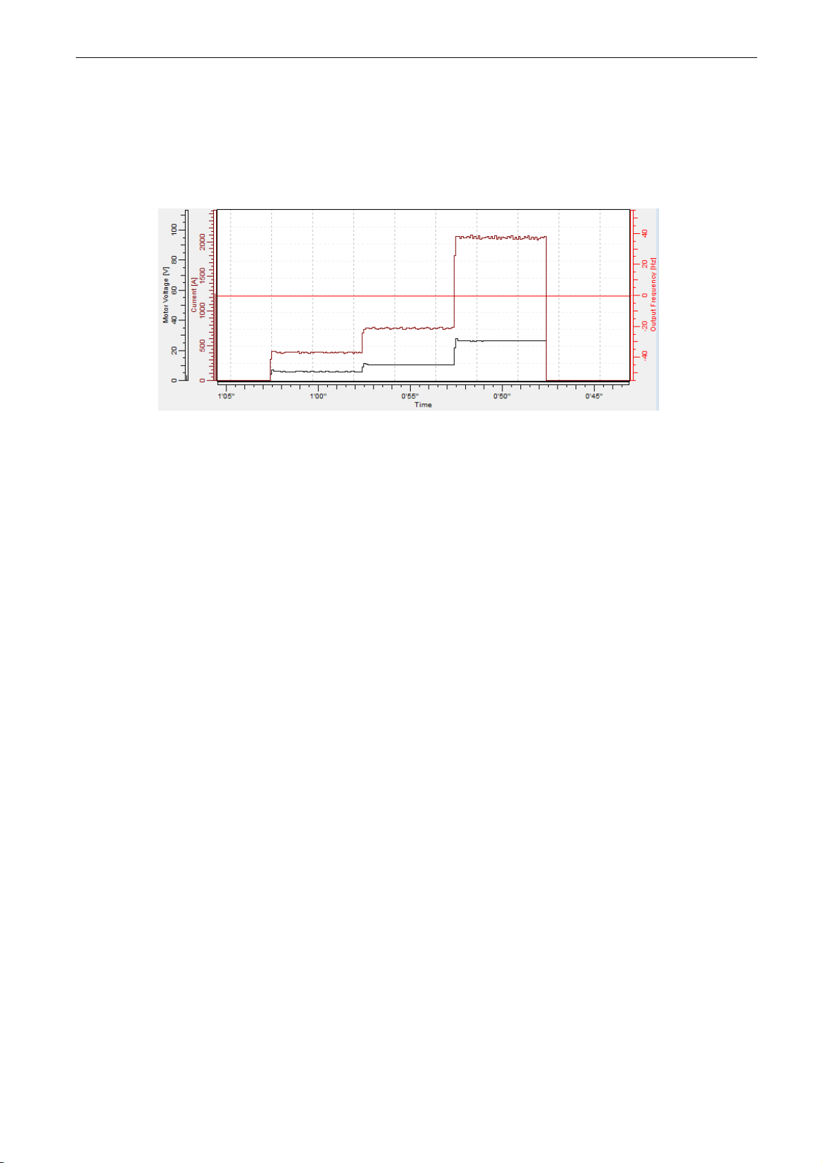
apfiff41 advanced high speed VACON® • 71
Local contacts: http://drives.danfoss.com/danfoss-drives/local-contacts/
Classified as Public
1 = “ID No Run” - Identification without rotating the motor
Current is applied to the motor but shaft will not be rotated. U/f settings are identified.
This identification is minimum requirement if motor is only to be used in open loop
control. It is however recommended to make always identification with rotating motor if
need for closed loop control comes after mechanics are connected to shaft.
Example of behaviour
Parameters updated during this identification
AM: PM:
P2.1.11 MagnCurrent P2.8.3.2 U/f Ratio Select
P2.8.3.2 U/f Ratio Select P2.8.3.5 U/f Mid Freq
P2.8.3.5 U/f Mid Freq P2.8.3.6 U/f Mid Voltg
P2.8.3.6 U/f Mid Voltg P2.8.3.7 Zero Freq Voltg
P2.8.3.7 Zero Freq Voltg P2.8.4.1 CurrentControlKp
P2.8.8.16 RsVoltageDrop P2.8.5.11 LsdVoltageDrop
P2.8.8.17 IrAddZeroPVoltag P2.8.5.12 LsqVoltageDrop
P2.8.8.22-24 Ix Offset P2.8.5.18 Curr. Contr. Kp d
P2.8.8.16 RsVoltageDrop
P2.8.8.17 IrAddZeroPVoltag
P2.8.8.20 LsVoltageDrop
P2.8.8.22-24 Ix Offset
P2.8.8.25 Estimator Kp
Page 72
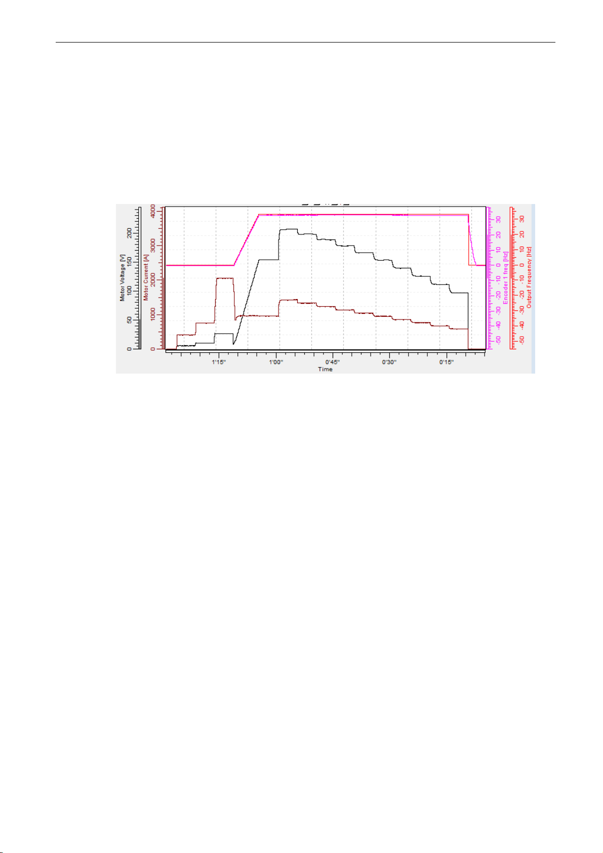
72 • VACON® apfiff41 Advance HS
Local contacts: http://drives.danfoss.com/danfoss-drives/local-contacts/
2 = “ID With Run” - Identification with motor rotating
Shaft is rotated during identification.
This identification must be run without load on motor shaft. U/f settings and
magnetization current are identified. This identification should be run regardless of the
final operation mode (closed loop or open loop) to get the best performance from the
motor. When identification with motor rotation is successfully finished the drive starts to
use internal slip estimator to compensate the motor temperature changed.
SCTorqueChainSelect B5 & B6.
Example of behaviour
Parameters updated during this identification
AM: PM:
P2.1.11 MagnCurrent P2.8.3.2 U/f Ratio Select
P2.8.3.2 U/f Ratio Select P2.8.3.3 Field WeakngPnt
P2.8.3.5 U/f Mid Freq P2.8.3.5 U/f Mid Freq
P2.8.3.6 U/f Mid Voltg P2.8.3.6 U/f Mid Voltg
P2.8.3.7 Zero Freq Voltg P2.8.3.7 Zero Freq Voltg
P2.8.8.16 RsVoltageDrop P2.8.4.1 CurrentControlKp
P2.8.8.17 IrAddZeroPVoltag P2.8.5.11 LsdVoltageDrop
P2.8.8.22-24 Ix Offset P2.8.5.12 LsqVoltageDrop
P2.8.8.1-15 Flux X % P2.8.5.18 Curr. Contr. Kp d
P2.8.8.16 RsVoltageDrop
P2.8.8.17 IrAddZeroPVoltag
P2.8.8.20 LsVoltageDrop
P2.8.8.21 MotorBEMVoltage
P2.8.8.22-24 Ix Offset
P2.8.8.25 Estimator Kp
Page 73

apfiff41 advanced high speed VACON® • 73
Local contacts: http://drives.danfoss.com/danfoss-drives/local-contacts/
Classified as Public
3 = “Enc. ID Run” - Encoder identification run
The motor shaft is rotated during identification.
IM: If performed for induction motor encoder pulse number and direction are identified.
Can be used if the is no encoder information available, correct result can be achieved
only when motor in unloaded.
PMSM: This selection is used for PMS motor if automatic angle identification is not
suitable for used motor (angle is identified automatically in every start if PMSM Shaft
Position parameter is zero).
This identification run will update PMSM Shaft Position parameter based on absolute
position of the encoder or Z pulse position of incremental type encoder.
Note: Identification needs to be remade if encoder position related to motor is changed
e.g. due maintenance.
Parameters updated during this identification
AM: PM:
P2.1.11 MagnCurrent P2.8.5.1 PMSMShaftPositio
P2.8.3.2 U/f Ratio Select P2.8.8.22-24 Ix Offset
P2.8.3.5 U/f Mid Freq P2.8.8.25 Estimator Kp
P2.8.3.6 U/f Mid Voltg
P2.8.3.7 Zero Freq Voltg
P2.8.8.16 RsVoltageDrop
P2.8.8.17 IrAddZeroPVoltag
P2.8.8.22-24 Ix Offset
P2.8.8.1-15 Flux X %
P7.3.1.2 Pulse revolution
P7.3.1.3 Invert direction
Page 74

74 • VACON® apfiff41 Advance HS
Local contacts: http://drives.danfoss.com/danfoss-drives/local-contacts/
4 = “Ident All” - Identified All
Shaft is rotated during identification.
All the above identification selections are made in sequence.
Parameters updated during this identification
AM: PM:
P2.1.11 MagnCurrent P2.8.3.2 U/f Ratio Select
P2.8.3.2 U/f Ratio Select P2.8.3.3 Field WeakngPnt
P2.8.3.5 U/f Mid Freq P2.8.3.5 U/f Mid Freq
P2.8.3.6 U/f Mid Voltg P2.8.3.6 U/f Mid Voltg
P2.8.3.7 Zero Freq Voltg P2.8.3.7 Zero Freq Voltg
P2.8.8.16 RsVoltageDrop P2.8.4.1 CurrentControlKp
P2.8.8.17 IrAddZeroPVoltag P2.8.5.11 LsdVoltageDrop
P2.8.8.22-24 Ix Offset P2.8.5.12 LsqVoltageDrop
P2.8.8.1-15 Flux X % P2.8.8.16 RsVoltageDrop
P2.8.8.17 IrAddZeroPVoltag
P2.8.8.20 LsVoltageDrop
P2.8.8.21 MotorBEMVoltage
P2.8.8.22-24 Ix Offset
P2.8.8.25 Estimator Kp
P2.8.5.1 PMSMShaftPositio
5 = “Enc.ABS.Lock” – Absolute encoder when locked rotor
Absolute encoder zero position identification when rotor is locked while using permanent
magnet motor.
It’s recommended to have shaft locked during this identification mode.
Parameters updated during this identification
PM:
P2.8.5.1 PMSMShaftPositio
P2.8.8.22-24 Ix Offset
P2.8.8.25 Estimator Kp
Page 75

apfiff41 advanced high speed VACON® • 75
Local contacts: http://drives.danfoss.com/danfoss-drives/local-contacts/
Classified as Public
10 = “ID Run Fails” - Identification failed
Identification failed in last attempt.
The basic motor name plate data has to be set correctly before performing the identification run:
- P2.1.3 – P2.1.8. Motor basic data.
- P2.1.9 Magnetization current can also be given if available if given before
identification without rotating motor; U/f curve will be tuned according to given
magnetization current.
- P2.1.11 Motor Type.
When in closed loop and with an encoder installed, also the parameter for pulses /
revolutions (in Menu M7) has to be set.
The automatic identification is activated by setting this parameter to the appropriate
value followed by a start command in the requested direction. The start command to the
drive has to be given within 20 s. If no start command is given within 20 s the identification run is cancelled and the parameter will be reset to its default setting. The identification run can be stopped any time with normal stop command and the parameter is
reset to its default setting. In case identification run detects fault or other problems, the
identification run is completed if possible. After the identification is finished, warning will
be given is not all requested identification types has been completed successfully.
During Identification Run, the brake control is disabled.
Note: After identification is made drive requires rising edge of start command.
Note: Advance application has all identified values stored to parameters, no need to redo
identification if previous parameters are loaded back to the dive if e.g. control board is
changed.
P2.1.13 Motor Type ID650 “Motor Type”
Select used motor type with this parameter
0 “Induction” - Induction motor
-Asynchronous motor
1 “PMSM” - Permanent magnet synchronous motor
- Contact factory before using with externally magnetized motor.
See related parameter in “G2.8.6: Motor Control \ PMSM Control”.
P2.1.14 Supply Voltage ID1201
This parameter can be used when license key P3.7 License 2 has been give.
This enables use of 690 Vac unit in voltage range of 500 Vac unit. Contact factory for
warranty and license issues.
Page 76

76 • VACON® apfiff41 Advance HS
Local contacts: http://drives.danfoss.com/danfoss-drives/local-contacts/
8.2 Reference Handling – “Ref Handling”
Priority order of Advance application speed reference chain.
SEL
G
IN 0
IN 1
Final Reference Location
PC PC Control
PC
PC Reference
SEL
G
IN 0
IN 1
AND
IN 1
IN 2
F Follower
F Ref from Master
SEL
G
IN 0
IN 1
FW
ConstantFreqRef6
FW
ConstantFreqRef7
F Ramp Follower
SEL
G
IN 0
IN 1
DI Enable Inching
P
Inching Ref 1 / 2
SEL
G
IN 0
IN 1
DI
(F)
Preset Speed
P(F) Preset Speeds
F 4 mA fault
SEL
G
IN 0
IN 1
P 4mA Fault Freq.
P Control Place
P I/O Reference
P Keypad Ref Sel
P Fieldbus Ctr Ref
SEL
G
IN 0
IN 1
P I/O Reference 2
DI I/O Ref 1/2
MUX
K
IN 0
IN 1
IN 2
IN 3
MIN
IN 1
IN 2
SEL
G
IN 0
IN 1
DI Max Frequency 2
P Max Frequency
P Max Frequency 2
Speed reference chain before ramp control
P SpeedShare
C 100,00
ADD
+
+
+
F Adjust Reference
FW FreqRef2
LIMIT
MN
IN
MX
P
Max Frequency
P Pos Freq Limit
LIMIT
MN
IN
MX
P -Max Frequency
P Neg Freq Limit
LIMIT
MN
IN
MX
Filt x2
IN
TC
OUT
V FreqReference
FW
FreqRefFilterTC
FW FreqRefActual
Switch
IN
TIME
OUT
P
Start 0SpeedTime
FW FreqRef1
Final Reference Location
RampControlIn
MULDIV
VALUE
MULTIP
DIVIS
Page 77

apfiff41 advanced high speed VACON® • 77
Local contacts: http://drives.danfoss.com/danfoss-drives/local-contacts/
Classified as Public
8.2.1 Basic Parameters
P2.2.1 Torque reference scale ID1247 “Torque Scale”
With this parameter the default resolution of torque reference 1000 = motor nominal
torque can be changed to 10000 = motor nominal torque.
NOTE! This function is available for closed loop control only.
0 1000: (100,0 %)
1 10000: (100,00 %)
All the torque related signals and parameters are changed and displayed automatically in
the same scale.
Parameters affected by this are presented below, and values should be checked before
starting the drive, values are not automatically changed when torque format is changed:
P2.2.12.2 Torque Ref Max
P2.2.12.3 Torque Ref Min
P2.2.12.5 TorqueRefDeadZone
P2.2.12.6 Torque Ref. Hyst
P2.2.12.12 Torque Step
P2.2.12.13 Torque Ref. Add
P2.3.13.4 Quick Stop T Lim
P2.6.3.1 Torque Limit
P2.6.3.2 MotorTorqueLimit
P2.6.3.3 GenerTorqueLimit
P2.6.3.6.1 SPC Out Limit
P2.6.3.6.2 SPC Pos Limit
P2.6.3.6.3 SPC Neg Limit
P2.6.5.12.2 CL OV ConMotTLim
P2.9.5.9 SPC Torq Min
P2.12.7.2 UP F0 Torque
P2.12.7.3 UP Fnom Torque
P2.15.9 MaxTorqLim
P2.2.2 I/O frequency reference selection 1 ID117 “I/O Reference”
Page 78

78 • VACON® apfiff41 Advance HS
Local contacts: http://drives.danfoss.com/danfoss-drives/local-contacts/
Defines which frequency reference source is used when control place is I/O terminal
P3.1 Control Place
0=”AI1” - Analogue Input 1.
Signal scaling in “G2.4.2: Input Signals \ Analogue Input 1”
1=”AI2” - Analogue Input 2.
Signal scaling in “G2.4.3: Input Signals \ Analogue Input 2”
2=”AI1+AI2” - Analogue Input 1 + Analogue Input 2.
With alternative reference scaling in Analogue Input group 100 % input values can be
set to correspond 25 Hz thus when both are at 100 % final reference will be 50 Hz.
3=”AI1-AI2”
Analogue Input 1 - Analogue Input 2.
4=”AI2-AI1”
Analogue Input 2 - Analogue Input 1.
5=”AI1xAI2”
Analogue Input 1 x Analogue Input 2
6=”AI1 Joystick”
Analogue input 1, -10 Vdc... +10 Vdc
7=”AI2 Joystick”
Analogue input 2, -10 Vdc... +10 Vdc
8=”Keypad Ref”
Reference from keypad R3.2
9=”Fieldbus”
Reference is taken from Fieldbus, alternative scaling can be selected in “G: Fieldbus”
10=”Motor Pot” - Motor potentiometer.
Reference handled with two digital input “G: Input Signals \ Digital Inputs” (increase
and decrease). Behaviour adjusted in “G: Ref Handling \ Motor Poten.mete”.
11=”AI1, AI2 min”
The minimum of Analogue Input 1 and Analogue Input 2 is used as reference.
12=”AI1, AI2 max”
The maximum from Analogue Input 1 and Analogue Input 2 is used as reference.
13=”Max Freq” – Maximum Frequency
P2.1.2 Max Frequency is used as reference.
14=”AI1/AI2 Sel” – AI1/AI2 Selection
Digital Input “I/O Ref 1/2” is used to select between Analogue Input 1 and Analogue
Input 2 reference. “I/O Ref 1/2” is sued to elect between “I/O Reference” and “I/O
Reference 2” if selection is different than 14 (this one).
15=”Encoder 1”
Reference is read from encoder input 1.
16=”Encoder 2”
Reference is read from encoder input 2. This selection is usable with double encoder
boards. Could be used e.g. for speed synchronization where two motor needs to run
at same speed but not necessarily same angle.
Page 79

apfiff41 advanced high speed VACON® • 79
Local contacts: http://drives.danfoss.com/danfoss-drives/local-contacts/
Classified as Public
P2.2.3 Keypad frequency reference selection ID121 “Keypad Ref Sel”
Defines which frequency reference source is used when control place is keypad P3.1
Control Place
0=”AI1” - Analogue Input 1.
Signal scaling in “G2.4.3: Input Signals \ Analogue Input 1”
1=”AI2” - Analogue Input 2.
Signal scaling in “G2.4.4: Input Signals \ Analogue Input 2”
2=”AI1+AI2” - Analogue Input 1 + Analogue Input 2.
With alternative reference scaling in Analogue Input group 100 % input values can be
set to correspond 25 Hz. That is, when both are at 100 % final reference will be 50
Hz.
3=”AI1-AI2”
Analogue Input 1 - Analogue Input 2.
4=”AI2-AI1”
Analogue Input 2 - Analogue Input 1.
5=”AI1xAI2”
Analogue Input 1 x Analogue Input 2
6=”AI1 Joystick”
Analogue input 1, -10 Vdc... +10 Vdc
7=”AI2 Joystick”
Analogue input 2, -10 Vdc... +10 Vdc
8=”Keypad Ref”
Reference from keypad R3.2
9=”Fieldbus”
Reference is taken from Fieldbus, alternative scaling can select in “G: Fieldbus”
P2.2.4 Fieldbus frequency reference selection ID122 “Fielsbus Ctr Ref”
Defines which frequency reference source is selected when control place is Fieldbus
P3.1. Control Place
0=”AI1” - Analogue Input 1.
Signal scaling in “G2.4.3: Input Signals \ Analogue Input 1”
1=”AI2” - Analogue Input 2.
Signal scaling in “G2.4.4: Input Signals \ Analogue Input 2”
2=”AI1+AI2” - Analogue Input 1 + Analogue Input 2.
With alternative reference scaling in Analogue Input group 100 % input values can be
set to correspond 25 Hz thus when both are at 100 % final reference will be 50 Hz.
3=”AI1-AI2”
Analogue Input 1 - Analogue Input 2.
4=”AI2-AI1”
Analogue Input 2 - Analogue Input 1.
5=”AI1xAI2”
Analogue Input 1 x Analogue Input 2
6=”AI1 Joystick”
Analogue input 1, -10 Vdc... +10 Vdc
7=”AI2 Joystick”
Analogue input 2, -10 Vdc... +10 Vdc
8=”Keypad Ref”
Reference from keypad R3.2
9=”Fieldbus”
Reference is taken from Fieldbus, alternative scaling can select in “G: Fieldbus”
Page 80

80 • VACON® apfiff41 Advance HS
Local contacts: http://drives.danfoss.com/danfoss-drives/local-contacts/
P2.2.5 I/O frequency reference selection 2 ID131 “I/O Reference 2”
This parameter is used to select different reference input location with digital input
P2.4.2.17 I/O Ref. 2. Selections for this are the same as for the I/O frequency reference
selection 1.
Other parameters related to function
- Digital input P2.4.2.17 I/0 Ref. 1/2
P2.2.6 Speed share ID1241 “Speed Share”
Defines the speed reference percentage ratio after final reference location but before
ramp control. Monitoring value “FreqReference” shows the reference after speed share
function. Used to adjust reference ration e.g. in line drive that PLC can give same
reference to all drives while speed share compensate gear ratio affect to the line speed.
P2.2.7 Load Share ID1248 “Load Share”
Defines the percentage for final torque reference after final torque reference location
selection but before the torque reference step function, torque reference dead zone and
reference filtering.
Page 81

apfiff41 advanced high speed VACON® • 81
Local contacts: http://drives.danfoss.com/danfoss-drives/local-contacts/
Classified as Public
8.2.2 Constant Reference
P2.2.7.1 Jogging speed reference ID124 “Jog Speed Ref”
Defines the jogging speed reference when activated by a digital input. This reference will
follow the reverse command if given. Jogging speed has a higher priority than preset
speed references.
Related parameters
- DigitalInput P2.4.2.16 Jogging Speed
P2.2.7.2 Preset speed 1 ID105 “Preset Speed 1”
P2.2.7.3 Preset speed 2 ID106 “Preset Speed 2”
P2.2.7.4 Preset speed 3 ID126 “Preset Speed 3”
P2.2.7.5 Preset speed 4 ID127 “Preset Speed 4”
P2.2.7.6 Preset speed 5 ID128 “Preset Speed 5”
P2.2.7.7 Preset speed 6 ID129 “Preset Speed 6”
P2.2.7.8 Preset speed 7 ID130 “Preset Speed 7”
Parameter values define the Preset speeds references activated by digital inputs. These
references will follow reverse command if given.
Speed
Digital Input
Preset speed
1
Digital Input
Preset speed 2
Digital Input
Preset speed 3
Basic speed
0 0 0
Preset Speed 1
1 0 0
Preset Speed 2
0 1 0
Preset Speed 3
1 1 0
Preset Speed 4
0 0 1
Preset Speed 5
1 0 1
Preset Speed 6
0 1 1
Preset Speed 7
1 1 1
Table 8-1. Preset speeds 1 to 7
Related parameters
Digital inputs P2.4.2.5-7 Preset Speed 1-3
8.2.2.1 Inching function
Inching function will start the drive to reference without additional start command regardless of
control place. Inching function requires enabling from digital input before command is accepted.
Inching is also disabled if there is start command active from active control place.
P2.2.7.9 Inching reference 1 ID1239 “Inching Ref 1”
P2.2.7.10 Inching reference 2 ID1240 “Inching Ref 2”
These parameters define the reference for the inching function. The references are bidirectional and
the reverse command does not affect the direction of the inching reference.
Other parameters for inching function
- Digital input selection: Enable Inching
- Digital input selection: Inching 1
- Digital input selection: Inching 2
- Parameter: Inching Ramp
Page 82
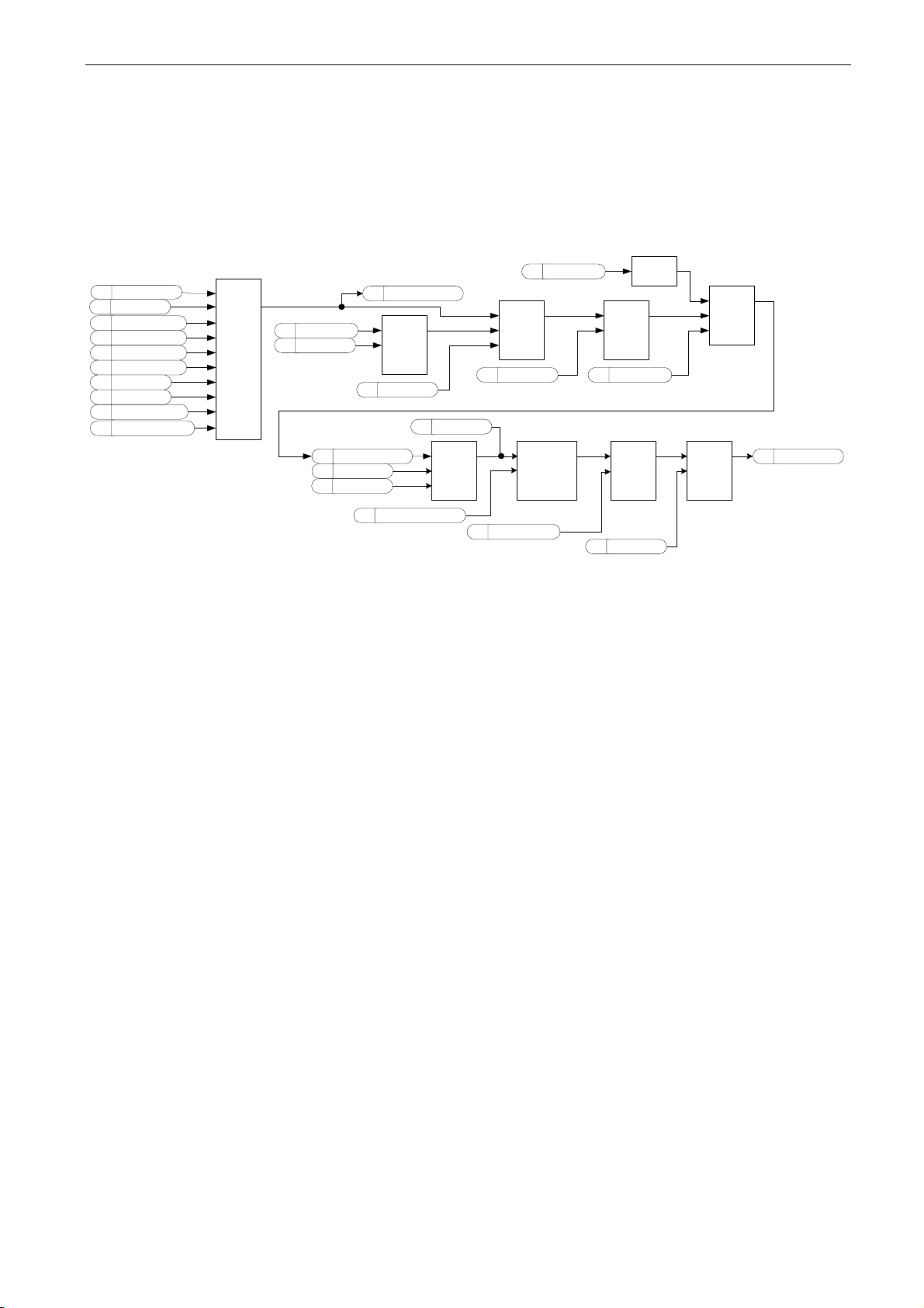
82 • VACON® apfiff41 Advance HS
Local contacts: http://drives.danfoss.com/danfoss-drives/local-contacts/
8.2.3 Torque Reference
Motor torque is controlled which allows the motor speed to change depending on the actual load on
the motor shaft. Speed limit behaviour is controlled by P2.2.9.6 TorqSpeedLimit parameter.
For joystick inputs maximum negative reference is negated “Torq Ref Max”. The minimum is used
only for analogue input selections 1 to 4. Also the maximum negative torque reference maximum is
negated “Torq Ref Max”.
P Torq Ref Select
F Analogue Input 1
F Analogue Input 2
F Analogue Input 4
F Analogue Input 3
C Not Used
F FieldBusReference
F Keypad Referece
F AI2 Joustck
F AI1 Joystick
MUX
K
IN 0
IN 1
IN 2
IN 3
IN 4
IN 5
IN 6
IN 7
IN 8
V Torque Reference
P
LoadShare
IN
DEAD ZONE
OUT
LIMIT
FW TorqueRef3
P TorqueRefDeadZone
V Torque Reference
ADD
+
+
P
TorqRefStep
Filt x2
IN
TC
OUT
P TorqRefFilterTC
MULDIV
VALUE
MULTIP
DIVIS
C 100,0
SUB
+
-
-
P Torq Ref Max
P Torq Ref Min
MULDIV
VALUE
MULTIP
DIVIS
C 10000
ADD
+
+
+
P Torq Ref Min
LIMIT
MN
IN
MX
P Torq Ref Max
P Torq Ref Max
NEG
IN
FW FinalTorqueRef
P2.2.9.1 Torque reference selection ID641 “Torq Ref Select”
0=”Not Used”
1=”AI1” - Analogue Input 1.
Signal scaling in “G: Input Signals \ Analogue Input 1”
2=”AI2” - Analogue Input 2.
Signal scaling in “G: Input Signals \ Analogue Input 2”
3=”AI3”
4=”AI4”
5=”AI1 Joystick”
Analogue input 1, -10 Vdc... +10 Vdc. For joystick inputs the maximum negative
reference is negated “Torq Ref Max”.
6=”AI2 Joystick”
Analogue input 2, -10 Vdc... +10 Vdc For joystick inputs the maximum negative
reference is negated “Torq Ref Max”.
7=”Keypad Ref”
Torque reference from keypad R3.5.
8=”Fieldbus”
Reference is taken from Fieldbus. Alternative scaling can be selected in “G: Fieldbus”
Page 83
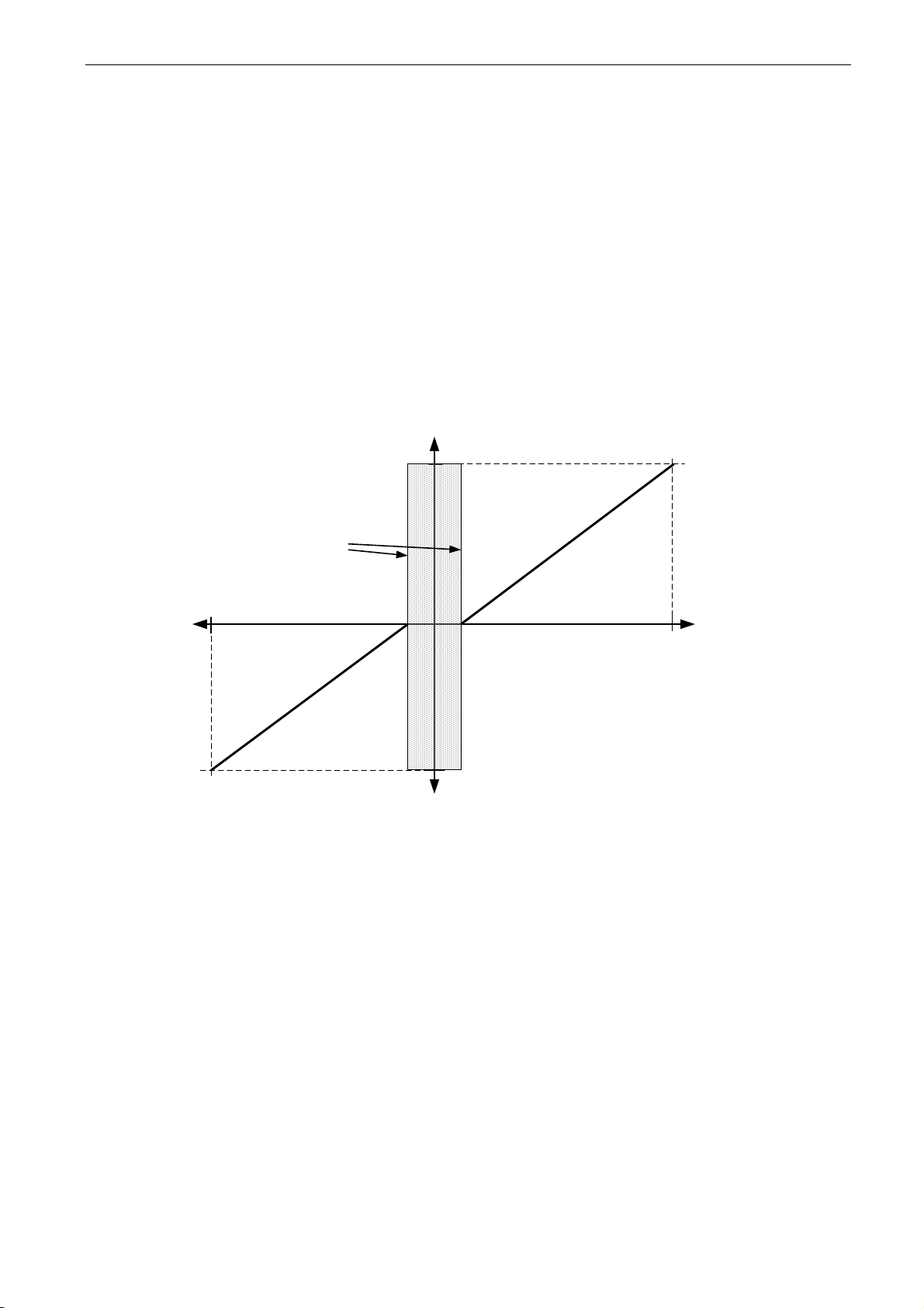
apfiff41 advanced high speed VACON® • 83
Local contacts: http://drives.danfoss.com/danfoss-drives/local-contacts/
Classified as Public
P2.2.9.2 Torque reference scaling, maximum value ID641 “Torq Ref Max”
Maximum allowed torque reference for positive and negative values. This is also used for
joystick input for negative maximum limit.
P2.2.9.3 Torque reference scaling, minimum value ID642 “Torq Ref Min”
Minimum torque reference for analogue input reference selections 1-4.
P2.2.9.4 Torque reference filtering time ID1244 “TorqRefFilterTC”
Defines the filtering time for torque reference. Filtering is after load share function and
before torque step function.
P2.2.9.5 Torque reference dead zone ID1246 “TorqRefDeadZone”
The small values of the torque reference around zero can be ignored by setting this
value greater than zero. When reference is between zero to plus/minus this parameter,
the reference is forced to zero.
+100 %
T max
- T max
Reference
-100 %
+10 %
-10 %
Dead Zone
10 %
Page 84
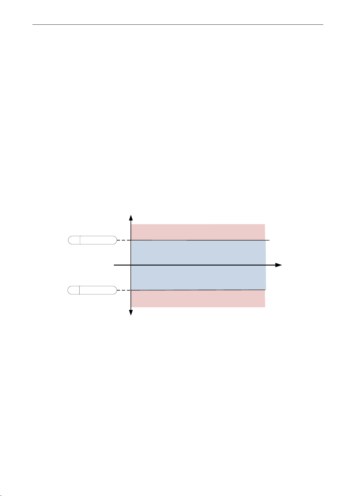
84 • VACON® apfiff41 Advance HS
Local contacts: http://drives.danfoss.com/danfoss-drives/local-contacts/
P2.2.9.6 Torque Speed Limit for Closed Loop ID1278 “TorqSpeedLimitCL”
This parameter defines the speed limiting mode in torque control mode. This parameter
can be used as single motor control mode selection when no change is made between
open loop and closed loop controls.
0 = Speed Control Mode SpeedControl
1 = Positive - Negative Frequency limits MaxFreqLimit
2 = RampOut (-/+) RampOutPut
3 = Negative frequency limit -- RampOut MIN
4 = RampOut - Positive frequency limit MAX
5 = RampOut in Window
6 = 0 -- RampOut
7 = RampOut in Window with On Off limits Window
0= “SpeedControl” - Speed control mode
The drive is forced to operate in speed control mode while the motor control mode
parameter is set to torque control mode thus allowing selection of speed control and
torque control mode with single parameter e.g. from Fieldbus.
1=”MaxFreqLimit” - Positive and negative frequency limits
Speed is not limited by speed reference, only maximum frequency or Positive and
Negative frequency limit if set lower than maximum frequency parameter.
speed controller active
speed controller active
P Pos Freq Limit
P Neg Freq Limit
Time
Drive in Torque Control
Drive in Torque Control
Speed
[RPM]
Page 85

apfiff41 advanced high speed VACON® • 85
Local contacts: http://drives.danfoss.com/danfoss-drives/local-contacts/
Classified as Public
2=”RampOutput” – Ramp output for both directions
Speed is limited by reference after ramp generator, thus speed will increase with set
ramp time until actual torque is equal to reference torque. If speed is below reference
when load is removed from the shaft the speed will increase without ramp.
This is the default selection. For master follower system it is recommended to use
selection that allows a little higher reference for torque follower that load will be balanced
equally e.g. window control.
speed controller active
Speed controller active
P
Neg Speed Limit
t
R FreqRampOut
Speed controller active
Speed
[RPM]
Drive in Torque Control
Drive in Torque Control
P Pos Freq Limit
FW FreqRampOut
Ramp Generator Out
Speed controller active
3=”Min” – Minimum from speed reference and torque reference.
The minimum of the speed controller output and the torque reference is selected as final
torque reference.
Time
speed controller active
speed controller active
Ramp Generator
output
P Pos Freq Limit
P Neg Freq Limit
FW FreqRampOut
Speed
[RPM]
Drive in Torque Control
Drive in Torque Control
Speed controller active
Drive in Torque Control
Speed controller active
Speed controller active
Speed controller active
4=”Max” – Maximum from speed reference and torque reference
Page 86
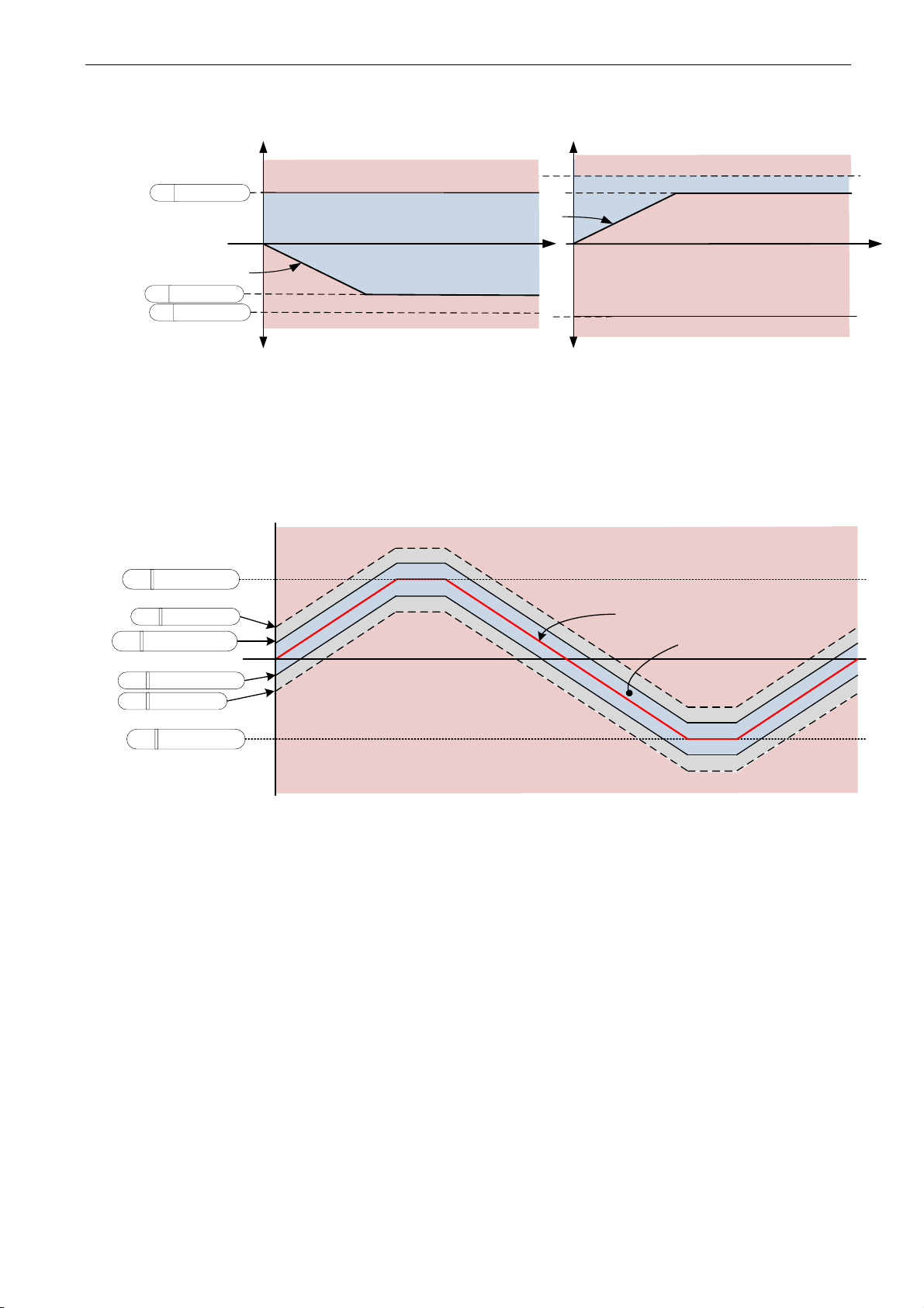
86 • VACON® apfiff41 Advance HS
Local contacts: http://drives.danfoss.com/danfoss-drives/local-contacts/
The maximum of the speed controller output and the torque reference is selected as final
torque reference.
speed controller active
speed controller active
Drive in Torque Control
speed controller active
Speed controller active
P Pos Freq Limit
R
Neg Freq Limit
Time
FW FreqRampOut
Speed controller active
Speed
[RPM]
Drive in Torque Control
Drive in Torque Control
speed controller active
speed controller active
7=”Window” – Window control
Speed is limited within window from speed reference.
Speed control activation limit is different from the speed limit. Speed needs, therefore, to
go first to “Window Pos” or “Window Neg” limit before the speed controller activates,
when speed controller is active speed will be restricted to limit defined by “Window Pos
Off” and “Windows Neg Off” from the “FinalFreqRef”
P Window Pos Off
P Window Neg Off
P Pos Freq Limit
P Neg Freq Limit
P Window Neg
P Window Pos
Speed controller active
Speed
Reference
Torque Control
area
Speed controller active
P2.2.9.7 Window negative ID1305 “Window Neg”
Defines the size of window to negative direction from the final speed reference. If both
windows off limits are zero this parameter is also the speed limit from the “FinalFreqRef”.
Otherwise this is the speed control activation limit.
P2.2.9.8 Window positive ID1304 “Window Pos”
Defines the size of window to positive direction from the final speed reference. If both
windows off limits are zero this parameter is also the speed limit from the “FinalFreqRef”.
Otherwise this is the speed control activation limit.
P2.2.9.9 Window negative Off limit ID1307 “Window Neg Off”
Defines the speed controller negative off limit when the speed controller brings the speed
back to window.
P2.2.9.10 Window positive Off limit ID1306 “Window Pos Off”
Defines speed controller positive off limit when speed controller brings speed back to
window.
Page 87

apfiff41 advanced high speed VACON® • 87
Local contacts: http://drives.danfoss.com/danfoss-drives/local-contacts/
Classified as Public
Page 88

88 • VACON® apfiff41 Advance HS
Local contacts: http://drives.danfoss.com/danfoss-drives/local-contacts/
8.2.3.1 Torque reference OL settings
P2.2.9.11.1 Open loop torque control minimum frequency ID636 “OL TC Min Freq”
Defines the frequency limit below which the frequency converter operates in frequency
control mode.
P2.2.9.11.2 Open loop torque controller P gain ID639 “OL TorqCtrl P”
Defines the gain for open loop torque control.
P2.2.9.11.3 Open loop torque controller I gain ID640 “OL TorqCtrl I”
Defines the integration gain for open loop torque control.
NOTE: This is a gain for integration part.
P2.2.9.11.4 Torque speed limit in Open Loop Control (2.10.7)
With this parameter the maximum frequency for the torque control can be selected.
0 Maximum frequency, par. ID102
1 Selected frequency reference
2 Preset speed 7, par. ID130
NXP drives have more selections for this parameter in Closed Loop control.
2.2.9.12.1 Torque step ID1253 “Torque Step”
Step torque reference in percentage of motor nominal torque. Added after the filtering
function and ramp function.
This step reference is normally used for the inertia/friction compensation of the drive
system through fieldbus in fieldbus control. E.g. the inertia compensation for winder or
unwinder roll can be written from fieldbus to this parameter.
Page 89
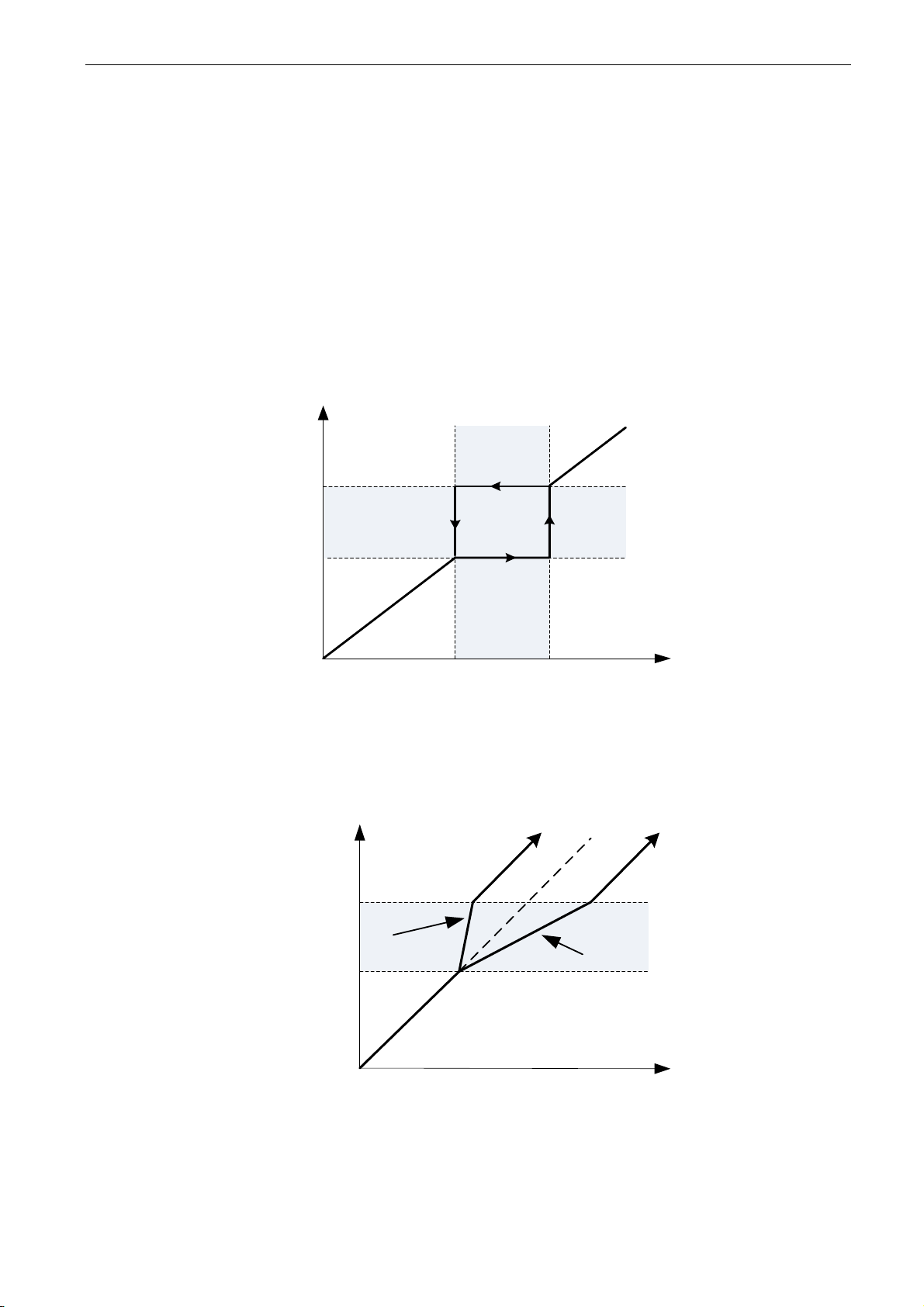
apfiff41 advanced high speed VACON® • 89
Local contacts: http://drives.danfoss.com/danfoss-drives/local-contacts/
Classified as Public
8.2.4 Prohibited frequencies
In some systems it may be necessary to avoid certain frequencies because of mechanical
resonance problems. With these parameters it is possible to set limits for the prohibited frequency
region and ramp rate factor to use when frequency is going above this area. When the input
reference is increased the internal reference is kept at the low limit until the input reference is above
the high limit.
P2.2.10.1 Prohibit frequency area 1; Low limit ID509 “Range 1 Low Lim”
P2.2.10.2 Prohibit frequency area 1; High limit ID510 “Range 1 High Lim”
Range definition where a different ramp time defined by “RampTimeFactor” is used.
Used
Speed Reference [RPM]
Requested Speed Reference
[RPM]
Low Lim
High Lim
P2.2.10.3 Ramp time factor for prohibited range ID518 “RampTimeFactor”
Multiplier of the currently selected ramp time between prohibit frequency limits.
Time [s]
Speed [RPM]
Low Lim
High Lim
Ramp Time
Factor = 2,5
Ramp Time
Factor = 0,3
Figure 8-1. Ramp rate scaling between prohibit frequencies
Page 90

90 • VACON® apfiff41 Advance HS
Local contacts: http://drives.danfoss.com/danfoss-drives/local-contacts/
8.2.5 Motor potentiometer
Motor potentiometer is used to control the reference with two digital inputs, one increasing the
reference and the other decreasing the reference. The reference change rate can be set by
parameter [Hz/s]. Motor potentiometer reference is available in I/O control only. It can be changed
only when the drive is in running state.
Time
[s]
Max
Speed
Min
Speed
Speed Ref
[RPM]
Motor Potentiometer
UP
Motor Potentiometer
DOWN
Motor Potentiometer
Ramp Rate
P2.2.11.1 Motor potentiometer ramp rate ID331 “MotPot Ramp Rate”
Defines the rate of change of the motor potentiometer reference value in Hz/s. Normal
ramp times are still active and determine how fast the actual output frequency increases.
P2.2.11.2 Motor potentiometer reference reset ID367 “MotPotRef Reset”
0 “No reset”
Reference is kept past the stop state and stored to memory in case of a powerdown.
1 “Stop State”
Reference is set to zero when the drive is in stop state. This selection includes
powerdown situations.
2 “Power Down”
Reference is reset only in a powerdown situation.
Other parameters related to function
- P2.4.2.8 Motor potentiometer DOWN ID417 “Mot Pot Ref Down”
- P2.4.2.9 Motor potentiometer UP ID418 “Mot Pot Ref Up”
Page 91

apfiff41 advanced high speed VACON® • 91
Local contacts: http://drives.danfoss.com/danfoss-drives/local-contacts/
Classified as Public
8.2.6 Adjust Reference
Adjust reference function is used to fine tune the main reference. Adjust reference is added to main
reference after “SpeedShare” function.
F Analogue Input 1
F
Analogue Input 2
F Analogue Input 4
F Analogue Input 3
F FB Adjust Reference
C 10000
P Adjust Max
P Adjust Min
FW FreqRef1
MULDIV
VALUE
MULTIP
DIVIS
MULDIV
VALUE
MULTIP
DIVIS
ADD
+
+
+
C 1000
F Adjust Reference
F Not Used
P Adjust Input
MUX
K
IN 0
IN 1
IN 2
IN 3
IN 4
IN 5
SUB
IN 1
IN 2
P Adjust Min
P2.2.12.1 Adjust input ID493 “Adjust Input”
With this parameter you can select the signal according to which the frequency reference
to the motor is fine adjusted.
0 Not used
1 Analogue input 1
2 Analogue input 2
3 Analogue input 3
4 Analogue input 4
5 FB Adjust Reference ID47 Monitoring Signal
P2.2.12.2 Adjust minimum ID494 “Adjust minimum”
Percentage that is subtracted from the main reference when adjust input is at minimum.
P2.2.12.3 Adjust maximum ID495 “Adjust Maximum”
These parameters define the minimum and maximum of adjusted signals.
Input Reference [Hz]
Reference [Hz]
Ajust Min 10 %
Ajust Max 10 %
25,0 Hz
27,5 Hz
22,5 Hz
Adjust input
If minimum and maximum are not equal to zero adjustment is not at the middlepoint of analogue
input or at zero point if -10...+10 Vdc input is used. Below picture minimum is 20 % and maximum 10
%.
Page 92

92 • VACON® apfiff41 Advance HS
Local contacts: http://drives.danfoss.com/danfoss-drives/local-contacts/
Adjust
Input [%]
Adjustment
10 %
20 %
50 %
100 %
66,66
P2.2.12.4 Speed Step ID1252
Page 93

apfiff41 advanced high speed VACON® • 93
Local contacts: http://drives.danfoss.com/danfoss-drives/local-contacts/
Classified as Public
8.3 Ramp control
SEL
G
IN 0
IN 1
R Final Ramp Time
P Ramp time 1
P Ramp time 2
DI Ramp time 1/2
SEL
G
IN 0
IN 1
DI Inching Active
P Inching Ramp
MULDIV
VALUE
MULTIP
DIVIS
F
Ramp Reduction
P 100 %
SEL
G
IN 0
IN 1
MULDIV
VALUE
MULTIP
DIVIS
F Prohibited area
P
1,0
P Prohibited Factor
SEL
G
IN 0
IN 1
F Ramp Follower
P
0,0 s
P2.3.1 Start function ID505 “Start Function”
Ramp:
0 The frequency converter starts from 0 Hz and accelerates to the set reference
frequency within the set acceleration time.
Flying start:
1 The frequency converter is able to start with motor running by applying current
to motor and searching for the frequency corresponding to the speed the motor
is running at. Searching starts from the maximum frequency towards the zero
frequency until the correct value is detected.
Use this mode if the motor is coasting when the start command is given. With
the flying start it is possible to start motor form actual speed without forcing the
speed to zero before ramping to reference.
Closed loop control will always start like flying start because exact speed of the motor is
known from encoder feedback.
P2.3.2 Stop function ID506 “Stop Function”
Coasting:
0 Drive stops controlling the motor immediately and let’s motor rotate freely.
Ramp:
1 After the Stop command, the speed of the motor is decelerated according to
the set deceleration parameters to zero speed. DI “Run Enable” will make
coasting stop regardless of selected stop function.
P2.3.3 Acceleration time 1 ID103 “Accel Time 1”
This parameter defines the time required for the output frequency to increase from the
zero frequency to maximum frequency.
P2.3.4 Deceleration time 1 ID104 “Decel Time 1”
This parameter defines the time required for the output frequency to decrease from the
maximum frequency to zero frequency.
Page 94

94 • VACON® apfiff41 Advance HS
Local contacts: http://drives.danfoss.com/danfoss-drives/local-contacts/
P2.3.5 Acceleration/Deceleration ramp 1 shape ID500 “Ramp 1 Shape”
The start and end of acceleration and deceleration ramps can be smoothed with these
parameters. Setting value 0 gives a linear ramp shape which causes acceleration and
deceleration to act immediately to the changes in the reference signal. Setting value
1…100 % for this parameter produces an S-shaped acceleration/deceleration.
Used to reduce mechanical erosion and current spikes when reference is changed.
Figure 8-2. 10 % S ramp with 3 s ramp time compared to without S ramp
Figure 8-3. 10 % S ramp with 3 s ramp time when reference set to zero at 25 Hz
P2.3.6 Acceleration time 2 ID502 “Accel Time 2”
P2.3.7 Deceleration time 2 ID503 “Decel
P2.3.8 Acceleration/Deceleration ramp 2 shape ID501 “Ramp 2 Shape”
These ramp times and ramp shapes are used when the second ramp time is activated by
digital input “Acc/Dec Time Sel”
0
10
20
30
40
50
60
00,591,181,772,362,953,544,134,725,315,96,497,087,678,268,859,44
0 % S
10 % S
0
5
10
15
20
25
30
35
40
0,00
0,38
0,76
1,14
1,52
1,90
2,28
2,66
3,04
3,42
3,80
4,18
4,56
4,94
5,32
5,70
6,08
10 % S
0 % S
Page 95

apfiff41 advanced high speed VACON® • 95
Local contacts: http://drives.danfoss.com/danfoss-drives/local-contacts/
Classified as Public
P2.3.9 Inching ramp ID1257 “Inching Ramp”
This parameter defines acceleration and deceleration times when inching is active.
Inching function will start the drive to reference without additional start command
regardless of control place. Inching function requires enabling from digital input before
command is accepted. Inching is also disabled if there is a start command active on the
active control place.
Other parameters for inching:
- Parameter: Inching Reference 1
- Parameter: Inching Reference 2
- Digital input selection: Enable Inching
- Digital input selection: Inching 1
- Digital input selection: Inching 2
P2.3.10 Reduction of acceleration and deceleration times ID401
Acceleration and deceleration times can be reduced with the input signal.
Input signal level zero means ramp times set by parameters. Maximum level equals one
tenth of the value set by parameter.
Adjust
Input [%]
Ramp Time Factor
100 %
10 %
Figure 8-4. Reducing acceleration and deceleration times
P2.3.11 Quick stop mode ID1276 “Quick Stop Mode”
Selects the mode of stopping the drive when quick stop is active.
• It is recommended to use same stop function in follower drives.
• It is recommended to use same ramp time in both drives
0 Coast stop.
1 Ramp stop.
P2.3.12 Quick Stop Ramp time ID1256
Page 96
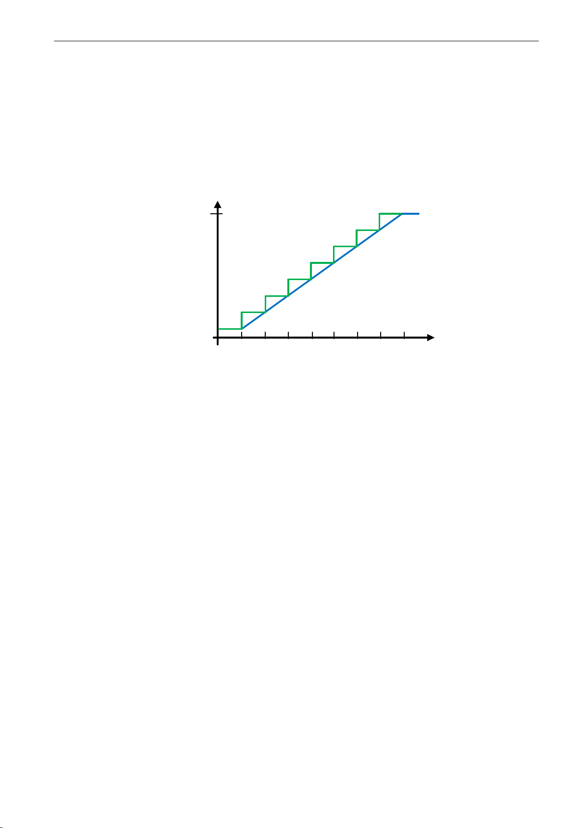
96 • VACON® apfiff41 Advance HS
Local contacts: http://drives.danfoss.com/danfoss-drives/local-contacts/
8.3.1 Ramp Options
P2.3.12.1 Frequency Reference Interpolator TC ID1184 “FreqRefInterp.TC”
Set here time on what interval speed reference is updated. This function ramps the
reference between updated values.
Function is used when PLC is updating reference e.g. 100 ms time level but drive own
ramp is set much shorter to have fast response. When reference (Green) is used without
interpolator also output frequency would behave same way causing torque and current
spikes every time reference changes. When interpolator time is set to 100 ms output
frequency behaves as blue line.
Reference
Time * 100 ms
P2.3.12.2 Ramp Time Format ID1500 “RampTimeFormat”
This parameter selects the format for ramp time. Thus enablin: use of very long ramp
times or very accurate ramp times.
0= # (3 s)
1= #,# (3,0 s)
2= #,## (3,00 s)
3= #,### (3,000 s)
Page 97
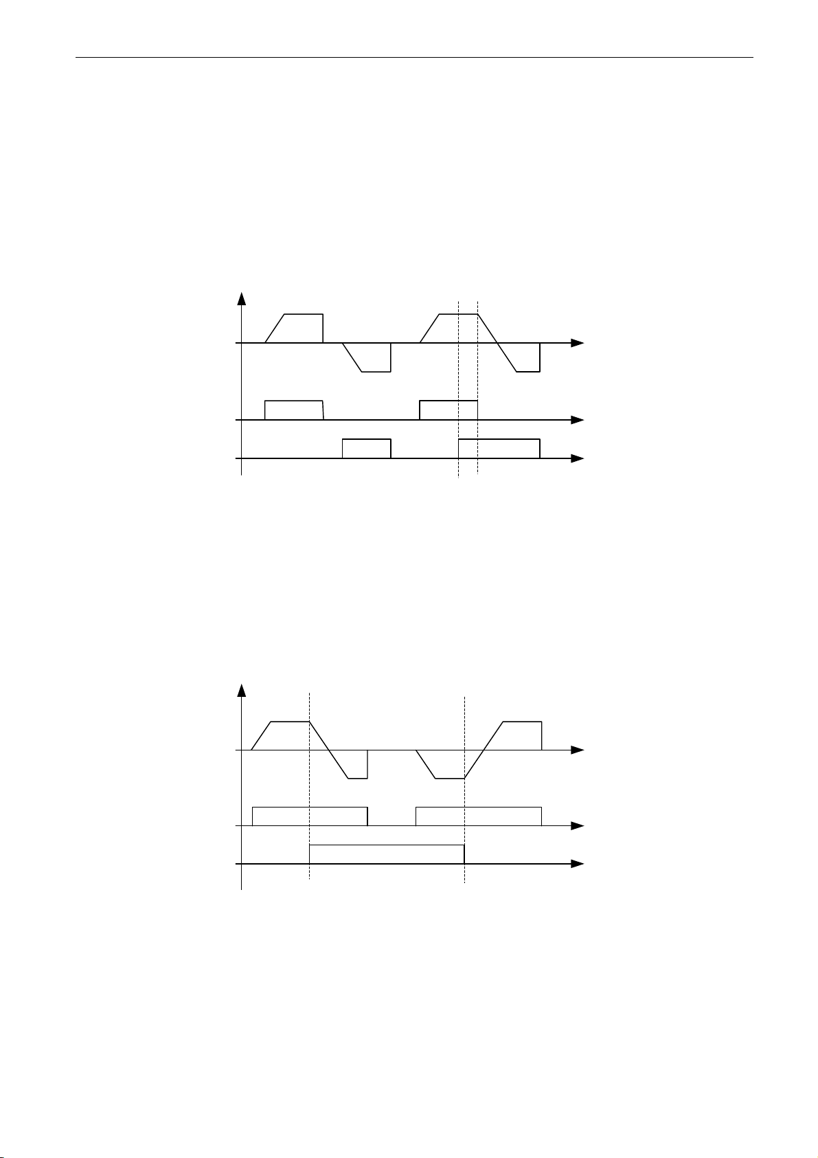
apfiff41 advanced high speed VACON® • 97
Local contacts: http://drives.danfoss.com/danfoss-drives/local-contacts/
Classified as Public
8.4 Input signals
8.4.1 Basic Settings
P2.4.1.1 Start/Stop logic selection ID300 “Start/Stop Logic”
This parameter defines start stop logic when using I/O control. Some of these selections
do not include the ’Reverse’ command. Reverse command can be activated by a
separate digital input “Reverse”.
0 “Forw – Rev” – Forward Start – Reverse Start
Start 1: closed contact = start forward DI “Start 1”
Start 2: closed contact = start reverse DI “Start 2”
Start 1
Start 2
Freq. Out
2
1
Figure 8-5. Start forward/Start reverse
The first selected direction has the highest priority.
When the DIN1 contact opens the direction of rotation starts the change.
1 “Start – Rev” - Start command – Direction command
Start 1: closed contact = start open contact = stop
Start 2: closed contact = reverse open contact = forward
Start 1
Start 2
Freq. Out
Figure 8-6. Start, Stop, Reverse
2 “Start – Enable” – Start command – Run Enable
DIN1: closed contact = start open contact = stop
DIN2: closed contact = start enabled open contact = start disabled and drive stopped
if running
Page 98
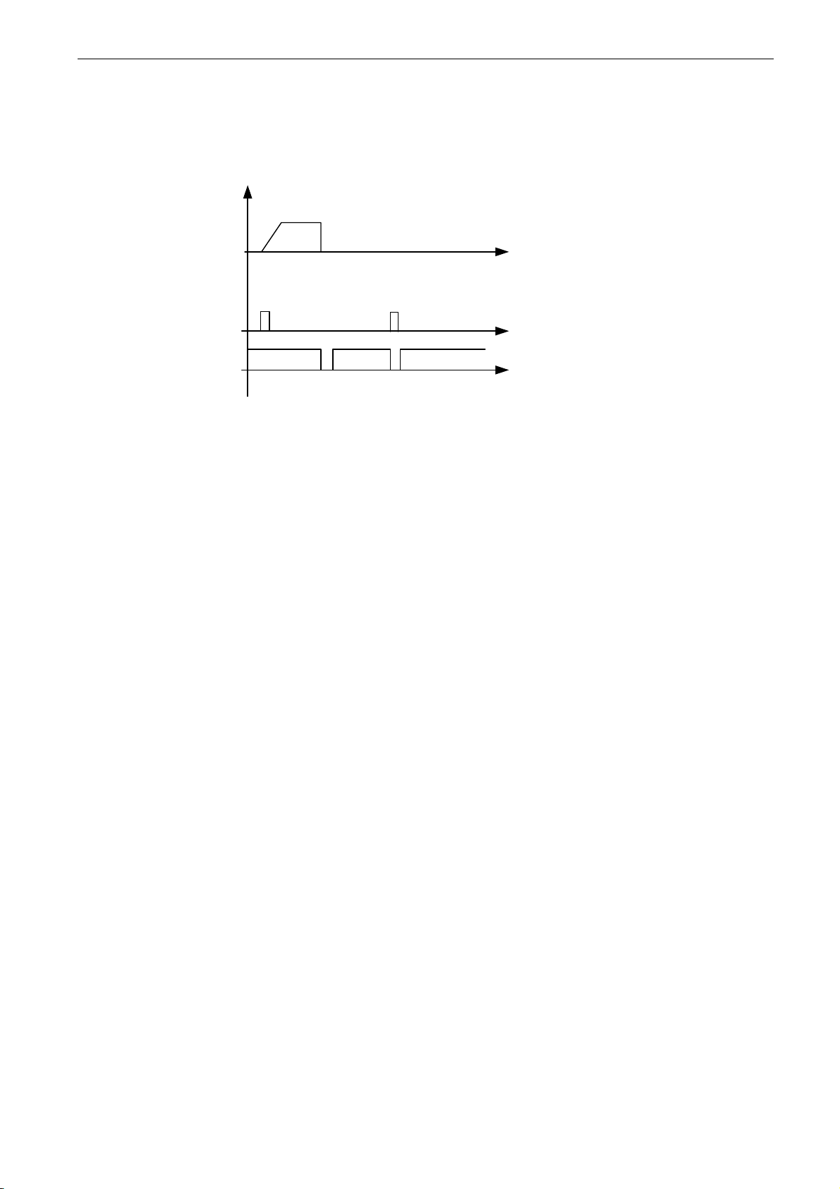
98 • VACON® apfiff41 Advance HS
Local contacts: http://drives.danfoss.com/danfoss-drives/local-contacts/
3 “StartP-StopP” – Start Pulse – Stop Pulse
3-wire connection (pulse control):
DIN1: closed contact = start pulse
DIN2: open contact = stop pulse, falling edge.
Start 1
Start 2
Freq. Out
Figure 8-7. Start pulse/ Stop pulse.
The selections including the text 'Rising edge required to start' shall be used to
exclude the possibility of an unintentional start when, for example, power is connected,
re-connected after a power failure, after a fault reset, after the drive is stopped by Run
Enable (Run Enable = False) or when the control place is changed. The Start/Stop
contact must be opened before the motor can be started.
4 “Strt-MotP UP” – Start – Motor potentiometer UP
DIN1: closed contact = start forward
DIN2: closed contact = Increases motor potentiometer reference, see Motor
potentiometer function for more details.
5 “ForwR – RevR” – Forward start rising edge – Reverse start rising edge
DIN1: closed contact = start forward (Rising edge required to start)
DIN2: closed contact = start reverse (Rising edge required to start)
6 “StartR-Rev” - Start command rising edge – Direction command
DIN1: closed contact = start (Rising edge required to start)
open contact = stop
DIN2: closed contact = reverse
open contact = forward
7 “StrtR-Enable” – Start command rising edge – Run Enable
DIN1: closed contact = start (Rising edge required to start)
open contact = stop
DIN2: closed contact = start enabled
open contact = start disabled and drive stopped if running
Page 99

apfiff41 advanced high speed VACON® • 99
Local contacts: http://drives.danfoss.com/danfoss-drives/local-contacts/
Classified as Public
8.4.2 Digital inputs
P2.4.2.1 Start signal 1 ID403 “Start Signal 1”
Signal selection 1 for the start/stop logic.
Default programming A.1.Default Forward start.
P2.4.2.2 Start signal 2 ID404 “Start Signal 2”
Signal selection 2 for the start/stop logic.
Default programming A.2. Default Reverse start.
P2.4.2.3 Run enable ID407 “Run Enable”
When run enable is removed from the drive coasting stop is made always.
Drive will also show warning indication when run is disabled.
Contact open: Start of motor disabled
Contact closed: Start of motor enabled
P2.4.2.4 Reverse ID412 “Reverse”
This reverse command is active when Start signal 2 is not used for reverse command
because setting of “Start/Stop logic selection” parameter.
Contact open: Direction forward
Contact closed: Direction reverse
P2.4.2.5 Preset speed 1 ID419 “Preset Speed 1”
P2.4.2.6 Preset speed 2 ID419 “Preset Speed 2”
P2.4.2.7 Preset speed 3 ID419 “Preset Speed 3”
Digital input selections for activating preset speeds.
References are set in the “Constant Reference” parameter group.
Speed
Digital Input
Preset speed 1
Digital Input
Preset speed 2
Digital Input
Preset speed 3
Basic speed
0 0 0
Preset Speed
1
1 0 0
Preset Speed
2
0 1 0
Preset Speed
3
1 1 0
Preset Speed
4
0 0 1
Preset Speed
5
1 0 1
Preset Speed
6
0 1 1
Preset Speed
7
1 1 1
Related parameters
- G2.2.7 Constant Ref
P2.4.2.8 Motor potentiometer DOWN ID417 “Mot Pot Ref Down”
Contact closed: Motor potentiometer reference DECREASES until the contact is
opened. See details in G2.2.11 Motor Pot.
Page 100

100 • VACON® apfiff41 Advance HS
Local contacts: http://drives.danfoss.com/danfoss-drives/local-contacts/
P2.4.2.9 Motor potentiometer UP ID418 “Mot Pot Ref Up”
Contact closed: Motor potentiometer reference DECREASES until the contact is
opened. See details in G2.2.11 Motor Pot.
P2.4.2.10 Fault reset ID414 “Fault Reset”
Rising edge required to reset fault.
P2.4.2.11 External fault closing contactor ID405 “Ext Fault Close”
External fault input closing contactor, response selected in protection parameter group
G2.11.1 Protections / General. Gives fault “51 Ext Fault”
P2.4.2.12 External fault opening contactor ID406 “Ext Fault Open”
External fault input opening contactor, response selected in protection parameter group.
Gives fault “51 Ext Fault”
P2.4.2.13 Acceleration/Deceleration time selection ID408 “Acc/Dec Time Sel”
Digital input to select between ramp time 1 and 2, times are set in “Ramp Control”
parameter group.
Contact open: Acceleration/Deceleration time 1 selected
Contact closed: Acceleration/Deceleration time 2 selected
P2.4.2.14 Acceleration/Deceleration prohibited ID415 “Acc/Dec Prohibit”
Contact closed: No acceleration or deceleration possible until the contact is opened.
With P2.9.3 Control Options B13 is possible to select that deceleration direction is
allowed thus speed is reduced if reference is smaller that drive speed at the time.
P2.4.2.15 DC-braking command ID416 “DC Brake Command”
Contact closed: In STOP mode, the DC braking operates until the contact is opened.
Current level is set with P2.7.1.16 DCBrakeCurInStop parameter.
P2.4.2.16 Jogging speed ID413 “Jogging Speed”
Contact closed: Jogging speed selected for frequency reference
Reference for jogging speed is set in G2.2.7 Constant Reference group.
P2.4.2.17 I/O Reference 1/2 selection ID422 “I/O Ref. 1/2"
With this parameter you can select either AI1 or AI2 signal for frequency reference if I/O
reference selection is “14 / AI1/AI2 Sel”.
If selection for P2.2.1 I/O Reference is other than “14 / AI1/AI2 Sel” this digital input will
change reference between P2.2.1 I/O Reference and P2.2.4 I/O Reference 2.
 Loading...