

Page 1

vacon
ac drives
®
nx
apfiff20
Crane control
Application manual
Page 2

Page 3

apfiff20 crane control 3 • VACON®
Local contacts: http://drives.danfoss.com/danfoss-drives/local-contacts/
Classified as Public
VACON CRANE CONTROL APPLICATION MANUAL
INDEX
Document code: DPD01974B
Software code: APFIFF20V099
Date: 31.7.2020
1. Crane Control Application - introduction ....................................................................................................... 8
1.1 General .................................................................................................................................................. 8
1.2 Basic Features ........................................................................................................................................ 9
1.3 Crane Control Application Compatibility issues ....................................................................................... 9
2. Quick Commissioning for crane features ...................................................................................................... 10
2.1 Mechanical Brake Control and Monitoring ............................................................................................ 10
2.2 Catch Dropping load ............................................................................................................................. 13
2.3 Tandem Operation for Cranes............................................................................................................... 13
2.4 Speed limit switch for Horizontal Movement ........................................................................................ 14
2.5 Anti-Sway ............................................................................................................................................. 14
2.6 Speed Optimization (Power dependant speed control) ......................................................................... 15
2.7 Bumpless transfer from closed loop to sensorless control ..................................................................... 15
2.8 Shock Load Prevention ......................................................................................................................... 15
2.9 Slack Rope Prevention .......................................................................................................................... 16
2.10 Integrated functional safety.................................................................................................................. 16
2.11 Load Estimation.................................................................................................................................... 16
3. Control I/O ................................................................................................................................................... 17
4. “Terminal To Function” (TTF) programming principle .................................................................................. 18
4.1 Defining an input/output for a certain function on keypad .................................................................... 18
4.2 Defining a terminal for a certain function with NCDrive programming tool ............................................ 19
4.3 Defining unused inputs/outputs ........................................................................................................... 20
5. Crane Control Application – monitoring values ............................................................................................ 21
5.1 Monitoring values ................................................................................................................................ 22
5.1.1 Monitoring values 1 ......................................................................................................................... 22
5.1.2 Monitoring values 2 ......................................................................................................................... 23
5.1.3 Fieldbus Monitoring values .............................................................................................................. 24
5.1.4 Master/Follower Monitoring values ................................................................................................. 24
5.1.5 PI Control Monitoring values ............................................................................................................ 24
5.1.6 Frequency Chain .............................................................................................................................. 25
5.1.7 Torque Chain.................................................................................................................................... 25
5.1.8 Brake Control ................................................................................................................................... 25
5.1.9 Motion ............................................................................................................................................. 25
5.1.10 Shaft Synch .................................................................................................................................. 25
5.1.11 Functional Safety Monitoring ....................................................................................................... 26
5.2 Monitoring Values description .............................................................................................................. 27
5.2.1 Monitoring values ............................................................................................................................ 27
5.2.2 Monitoring values 2 ......................................................................................................................... 29
5.2.3 FieldBus Monitoring values .............................................................................................................. 33
5.2.4 Master / Follower............................................................................................................................. 39
5.2.5 PI Control monitoring ....................................................................................................................... 42
5.2.6 Frequency Chain .............................................................................................................................. 42
5.2.7 Torque Chain.................................................................................................................................... 43
5.2.8 Brake Control ................................................................................................................................... 43
5.2.9 Motion ............................................................................................................................................. 44
Page 4

4 • VACON® apfiff20 crane control
Local contacts: http://drives.danfoss.com/danfoss-drives/local-contacts/
Classified as Public
5.2.10 Tandem Operation (Shaft Synch) .................................................................................................. 44
5.2.11 Functional Safety Monitoring ....................................................................................................... 45
5.2.12 Counters ...................................................................................................................................... 51
6. Crane Control Application – Parameter lists ................................................................................................. 53
6.1 Basic parameters .................................................................................................................................. 53
6.2 Reference Handling .............................................................................................................................. 54
6.2.1 Basic Settings ................................................................................................................................... 54
6.2.2 Constant Reference .......................................................................................................................... 54
6.2.3 Torque Reference............................................................................................................................. 55
6.2.4 Prohibit frequency parameters ......................................................................................................... 56
6.2.5 Motor Potentiometer ....................................................................................................................... 56
6.2.6 Adjust Reference .............................................................................................................................. 56
6.2.7 End limits reference handling ........................................................................................................... 57
6.3 Ramp Control ....................................................................................................................................... 58
6.3.1 Basic Settings ................................................................................................................................... 58
6.3.2 Quick Stop........................................................................................................................................ 58
6.3.3 Ramp Control Options ...................................................................................................................... 58
6.3.4 Slack Rope and Shock Load functions................................................................................................ 59
6.4 Input Signals ......................................................................................................................................... 60
6.4.1 Basic Settings ................................................................................................................................... 60
6.4.2 Digital inputs .................................................................................................................................... 61
6.4.3 Analogue input 1 .............................................................................................................................. 62
6.4.4 Analogue input 2 .............................................................................................................................. 62
6.4.5 Analogue input 3 .............................................................................................................................. 63
6.4.6 Analogue input 4 .............................................................................................................................. 63
6.4.7 Options ............................................................................................................................................ 63
6.5 Output Signals ...................................................................................................................................... 64
6.5.1 Digital output signals ........................................................................................................................ 64
6.5.2 Analogue output 1 ........................................................................................................................... 65
6.5.3 Analogue output 2 ........................................................................................................................... 65
6.5.4 Analogue output 3 ........................................................................................................................... 66
6.5.5 Analogue output 4 ........................................................................................................................... 66
6.5.6 Delayed digital output 1 ................................................................................................................... 67
6.5.7 Delayed digital output 2 ................................................................................................................... 67
6.5.8 Supervision Limits ............................................................................................................................ 68
6.6 Limit Settings........................................................................................................................................ 69
6.6.1 Current handling .............................................................................................................................. 69
6.6.2 Torque Handling............................................................................................................................... 69
6.6.3 Frequency Handling ......................................................................................................................... 70
6.6.4 DC-Link Handling .............................................................................................................................. 71
6.6.5 Limit Settings Options ...................................................................................................................... 71
6.7 Flux and DC Current handling ............................................................................................................... 72
6.7.1 Flux and DC Current handling OL Settings ......................................................................................... 72
6.7.2 Flux and DC Current handling CL Settings.......................................................................................... 72
6.8 Motor Control ...................................................................................................................................... 73
6.8.1 Motor Control Basic Settings ............................................................................................................ 73
6.8.2 Open Loop Settings .......................................................................................................................... 73
6.8.3 Closed Loop Control Settings ............................................................................................................ 74
6.8.4 PMSM Control settings ..................................................................................................................... 75
6.8.5 Stabilators ........................................................................................................................................ 76
6.8.6 Tuning parameters ........................................................................................................................... 76
6.8.7 Identification parameters ................................................................................................................. 77
6.8.8 Fine tuning parameters .................................................................................................................... 78
6.8.9 AOL Control Tuning parameters ....................................................................................................... 78
6.9 Speed Control ...................................................................................................................................... 79
6.9.1 Speed Control Basic settings ............................................................................................................. 79
Page 5

apfiff20 crane control 5 • VACON®
Local contacts: http://drives.danfoss.com/danfoss-drives/local-contacts/
Classified as Public
6.9.2 Speed Control OL Settings ................................................................................................................ 79
6.9.3 Speed Control CL Settings ................................................................................................................. 79
6.10 Drive Control ........................................................................................................................................ 79
6.11 Master Follower Control Parameters .................................................................................................... 80
6.12 Protections ........................................................................................................................................... 82
6.12.1 General settings ........................................................................................................................... 82
6.12.2 Temperature sensor protections .................................................................................................. 82
6.12.3 Stall Protection ............................................................................................................................ 83
6.12.4 Speed error monitoring ................................................................................................................ 83
6.12.5 Motor thermal protections........................................................................................................... 83
6.12.6 Living Zero monitoring ................................................................................................................. 84
6.12.7 Underload protection................................................................................................................... 84
6.12.8 Earth Fault protection .................................................................................................................. 84
6.12.9 Cooling protection ....................................................................................................................... 84
6.12.10 Fieldbus protection ...................................................................................................................... 85
6.12.11 External Fault ............................................................................................................................... 85
6.12.12 Encoder Fault ............................................................................................................................... 85
6.12.1 Options ........................................................................................................................................ 85
6.13 Fieldbus parameters ............................................................................................................................. 85
6.13.1 Value Control ............................................................................................................................... 88
6.13.2 DIN ID Control 1 ........................................................................................................................... 88
6.13.3 DIN ID Control 2 ........................................................................................................................... 88
6.13.4 DIN ID Control 3 ........................................................................................................................... 88
6.13.5 ID Controlled Digital Output 1 ..................................................................................................... 89
6.13.6 ID Controlled Digital Output 2 ...................................................................................................... 89
6.13.7 Free DIN Delay ............................................................................................................................. 89
6.14 Brake Control Parameters..................................................................................................................... 90
6.14.1 Brake Control Start up torque for CL............................................................................................. 90
6.14.2 Roll Back Control for CL ................................................................................................................ 90
6.14.3 Brake Fault handling .................................................................................................................... 91
6.14.4 Functions ..................................................................................................................................... 91
6.14.5 Brake Test Function ..................................................................................................................... 91
6.15 Auto Reset parameters ......................................................................................................................... 92
6.16 PI Control Parameters .......................................................................................................................... 92
6.17 Shaft Synchronization ........................................................................................................................... 93
6.18 Load Estimation.................................................................................................................................... 93
6.19 Functional Safety .................................................................................................................................. 93
6.20 Anti-Swing Function ............................................................................................................................. 94
6.21 Keypad control (Control keypad: Menu M3) ......................................................................................... 95
6.22 System menu (Control keypad: Menu M6) ............................................................................................ 95
6.23 Expander boards (Control keypad: Menu M7) ....................................................................................... 95
7. Description of parameters ........................................................................................................................... 96
7.1 Basic Parameters .................................................................................................................................. 96
7.2 Reference Handling – “Ref Handling” ...................................................................................................106
7.2.1 Basic Parameters .............................................................................................................................107
7.2.2 Constant Reference .........................................................................................................................110
7.2.3 Torque Reference............................................................................................................................112
7.2.4 Prohibited frequencies ....................................................................................................................118
7.2.5 Motor potentiometer ......................................................................................................................119
7.2.6 Adjust Reference .............................................................................................................................121
7.2.1 Speed limits reference handling for horizontal movement ...............................................................123
7.3 Ramp control ......................................................................................................................................125
7.3.1 Ramp Options .................................................................................................................................129
7.3.2 Slack Rope and Shock Load ..............................................................................................................131
7.4 Input signals ........................................................................................................................................132
7.4.1 Basic Settings ..................................................................................................................................132
Page 6

6 • VACON® apfiff20 crane control
Local contacts: http://drives.danfoss.com/danfoss-drives/local-contacts/
Classified as Public
7.4.2 Digital inputs ...................................................................................................................................134
7.4.3 Analogue Input 1 & 2.......................................................................................................................140
7.4.4 Analogue input 3 & 4 .......................................................................................................................145
7.4.5 Inversion control .............................................................................................................................148
7.5 Output signals .....................................................................................................................................149
7.5.1 Digital output signals .......................................................................................................................149
7.5.2 Analogue outputs 1 & 2 & 3 & 4 ......................................................................................................154
7.5.3 Delayed Digital Output 1 & 2 ...........................................................................................................158
7.5.4 Supervision limits ............................................................................................................................161
7.6 Limit settings .......................................................................................................................................163
7.6.1 Current limit handling .....................................................................................................................163
7.6.2 Torque limit handling ......................................................................................................................164
7.6.3 Frequency limit handling .................................................................................................................167
7.6.4 DC Link handling..............................................................................................................................169
7.6.5 Limit options ...................................................................................................................................172
7.7 DC current and magnetization handling ...............................................................................................173
7.7.1 Open loop settings ..........................................................................................................................174
7.7.2 Closed loop settings ........................................................................................................................177
7.8 Motor Control .....................................................................................................................................179
7.8.1 Open Loop Settings .........................................................................................................................184
7.8.2 Close Loop Settings .........................................................................................................................188
7.8.3 Permanent magnet synchronous motor settings..............................................................................191
7.8.4 Stabilization settings .......................................................................................................................197
7.8.5 Tuning settings ................................................................................................................................200
7.8.6 Identification settings .....................................................................................................................202
7.8.7 AOL control for IM...........................................................................................................................204
7.9 Speed Control settings.........................................................................................................................205
7.10 Drive Control .......................................................................................................................................211
7.11 Master-Follower ..................................................................................................................................214
7.11.1 Master-Follower: Standard system ..............................................................................................214
7.11.2 Master Follower: DriveSynch system ...........................................................................................215
7.11.3 Master-Follower configuration ....................................................................................................218
7.12 Protections ..........................................................................................................................................223
7.12.1 General settings ..........................................................................................................................223
7.12.2 Temperature sensor protections .................................................................................................224
7.12.3 Stall protection ...........................................................................................................................226
7.12.4 Speed Error .................................................................................................................................228
7.12.5 Motor Protection ........................................................................................................................229
7.12.6 Over Load Protection ..................................................................................................................232
7.12.7 4mA Protection ...........................................................................................................................233
7.12.8 Underload protection..................................................................................................................234
7.12.9 Earth Fault ..................................................................................................................................236
7.12.10 Cooling protection ......................................................................................................................236
7.12.11 Fieldbus communication .............................................................................................................237
7.12.12 External Fault function ................................................................................................................237
7.12.13 Encoder Fault function ................................................................................................................238
7.13 Fieldbus settings..................................................................................................................................240
7.13.1 General settings ..........................................................................................................................240
7.14 ID Functions ........................................................................................................................................244
7.14.1 Value Control ..............................................................................................................................244
7.14.2 DIN ID Control .............................................................................................................................246
7.14.3 ID-controlled DO .........................................................................................................................247
7.14.4 Free DIN Delay ............................................................................................................................248
7.15 Brake Control ......................................................................................................................................249
7.15.1 Brake time control timing in closed loop......................................................................................250
7.15.2 Brake control timing in open loop ...............................................................................................251
7.15.3 Start Up torque ...........................................................................................................................254
Page 7

apfiff20 crane control 7 • VACON®
Local contacts: http://drives.danfoss.com/danfoss-drives/local-contacts/
Classified as Public
7.15.4 Roll Back Control for Closed Loop ................................................................................................255
7.15.5 Brake monitoring function ..........................................................................................................256
7.15.6 Functions ....................................................................................................................................258
7.15.7 Brake Test Function ....................................................................................................................258
7.16 Auto Fault Reset ..................................................................................................................................259
7.17 PI Control ............................................................................................................................................262
7.18 Tandem operation ...............................................................................................................................264
7.19 Load Estimation...................................................................................................................................265
7.20 Functional Safety .................................................................................................................................266
7.21 Anti-Swing Function ............................................................................................................................267
7.22 Keypad control parameters .................................................................................................................270
8. Identification function for permanent magnet synchronous motor ............................................................271
8.1 Identification with absolute encoder. ..................................................................................................271
8.2 Identification with incremental encoder without Z-pulse input ............................................................271
8.3 Identification with incremental encoder with Z-pulse input..................................................................272
9. Status and control word in detail ................................................................................................................273
9.1 Fieldbus ..............................................................................................................................................273
9.1.1 Combination 1, ProfiDrive – Standard with Profibus option board....................................................274
9.1.2 Combination 2, ByPass – ProfiDrive .................................................................................................275
9.1.3 Combination 3, ByPass – Standard ...................................................................................................282
9.2 Application Status Word ......................................................................................................................283
9.3 Regulator Status ..................................................................................................................................283
9.4 Data Logger Trigger Word ....................................................................................................................284
9.5 MC Status Word ..................................................................................................................................284
9.6 Brake Control Status ............................................................................................................................285
10. Problem solving ......................................................................................................................................287
11. Fault codes..............................................................................................................................................288
Page 8
8 • VACON® apfiff20 crane control
Local contacts: http://drives.danfoss.com/danfoss-drives/local-contacts/
Classified as Public
1. CRANE CONTROL APPLICATION - INTRODUCTION
Software APFIFF20, Crane Control application
Crane Control application is designed for use in crane systems.
1.1 General
This application is not backwards compatible. Please read the application change note or
chapter 2: Brake Control versions compatibility issues in this manual to see what needs to be
noted when updating the application. See also the updated parameter description in NCDrive
when commissioning.
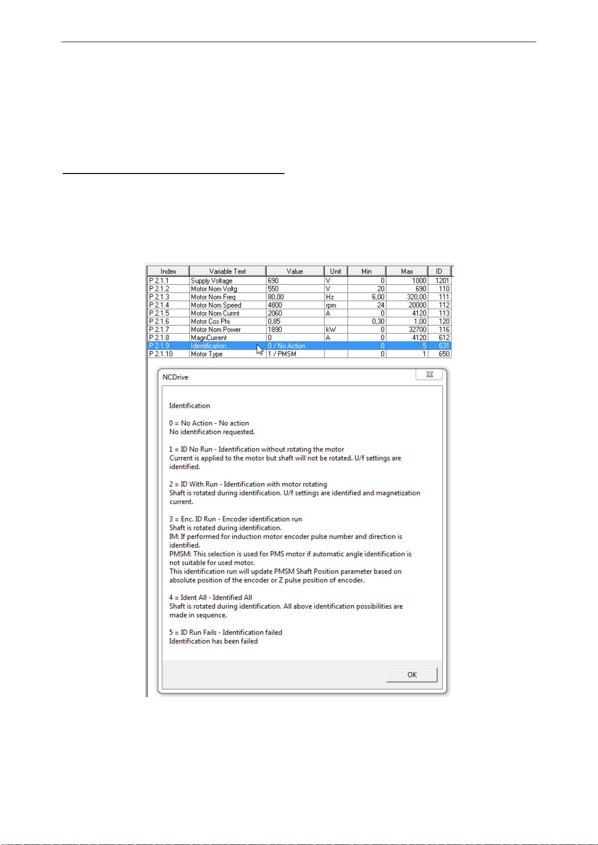
Help is available in NCDrive through selecting “Variable Text” and pressing “F1”.
See below an example from the Identification parameter help text from the NCDrive.
Page 9

apfiff20 crane control 9 • VACON®
Local contacts: http://drives.danfoss.com/danfoss-drives/local-contacts/
Classified as Public
1.2 Basic Features
The Crane Control application provides a wide range of parameters for controlling induction
motors and permanent magnet motors. It can be used for various kinds of different processes
where wide flexibility of I/O signals is needed and only simple PI control logic.
Flexible ID control possibilities takes the application suitability to different processes to a new
level, allowing any input or actual value to be connected to any parameter with a scaling factor.
Additional functions:
• Joystick input dead zone
• Master-Follower function
• Cooling monitor input from heat exchange unit with selectable response
• Brake monitoring input and actual current monitor for immediate brake close
• Separate speed control tuning for different speeds and loads
• Inching function with two different references
• Possibility to connect FB Process data to any parameter and some monitoring values
• Analogue input 3 and 4 can control any parameter by ID number
• Support for four analogue outputs
• Support for two PT100 boards
• Roll-Back control and Torque memory
• Brake slipping monitor (Start to falling load)
1.3 Crane Control Application Compatibility issues
Page 10

10 • VACON® apfiff20 crane control
Local contacts: http://drives.danfoss.com/danfoss-drives/local-contacts/
Classified as Public
2. QUICK COMMISSIONING FOR CRANE FEATURES
2.1 Mechanical Brake Control and Monitoring
The Mechanical Brake Control function in drive supports to build-up torque smoothly against the
closed brake before releasing the mechanical brake for smooth startup , and drive will continue
to deliver torque until mechanical brake control takes over the command.
Mechanical brake control parameters are in the group G 2.15.x.
See chapter 8.15 Brake Control for more details on parameters and their behaviour.
Easy commissioning tips for Mechanical Brake Control:
The application software makes calculations for parameter setting during the identification run
based on motor nominal parameters, brake mechanical opening delay (P2.15.3) and brake
mechanical closing delay (P2.15.4).
1. Enter motor name plate value G2.1 Basic Parameters.
a. Enter motor magnetization current P2.1.8 if known (calculated from Cos Phi if not
given).
2. Make identification run in standstill with P2.1.9 Identification: selection 1 - ID No Run.
a. If magnetization current is not known, arrange so that Identification selection 6 -
U/f + magn ID run can be made.
3. After identification, upload the parameters from the drive.
4. Brake related parameters are gathered to G2.15.
a. Select output for controlling the brake P2.15.1 BrakeOpen, Direct.
b. Select feedback input if used: P2.15.2 Brake Feedback.
c. Enter brake mechanical time delay for opening the brake: P2.15.3.
d. Enter brake mechanical time delay for closing the brake: P2.15.4.
e. Depending on system, Brake Timing identification run can be made.
5. Make necessary parameter changes to control place and control signal.
6. Make Crane ID Run for hoisting P2.1.11 Crane Identification modes.
a. If mode accurate timings for brake are found during commissioning, it is
recommended to make Crane Identification again. See detailed list of modified
parameters from P2.1.11 explanation.
7. Make Open Loop run without load with monitoring signals below.
a. Use ~7 ms monitoring interval if possible (see chapter 10 Problem Solving).
- Value: BrakeStatusWord
- Value: Motor Torque
- Value: Motor Current
- Value: Freq.Ramp Out
- Value: Output Frequency
- Value: Shaft Frequency
- Value: Motor Voltage
- Value: DC Voltage
b. Monitor that Shaft Frequency from encoder is correct.
In some cases, filtering a few ms may be needed: P2.8.5.6.
c. See that current and torque do not show abnormal behaviour.
8. Change to Closed Loop Control P2.8.1 Motor Control Mode: 3 / CL Speed Control.
Page 11
apfiff20 crane control 11 • VACON®
Local contacts: http://drives.danfoss.com/danfoss-drives/local-contacts/
Classified as Public
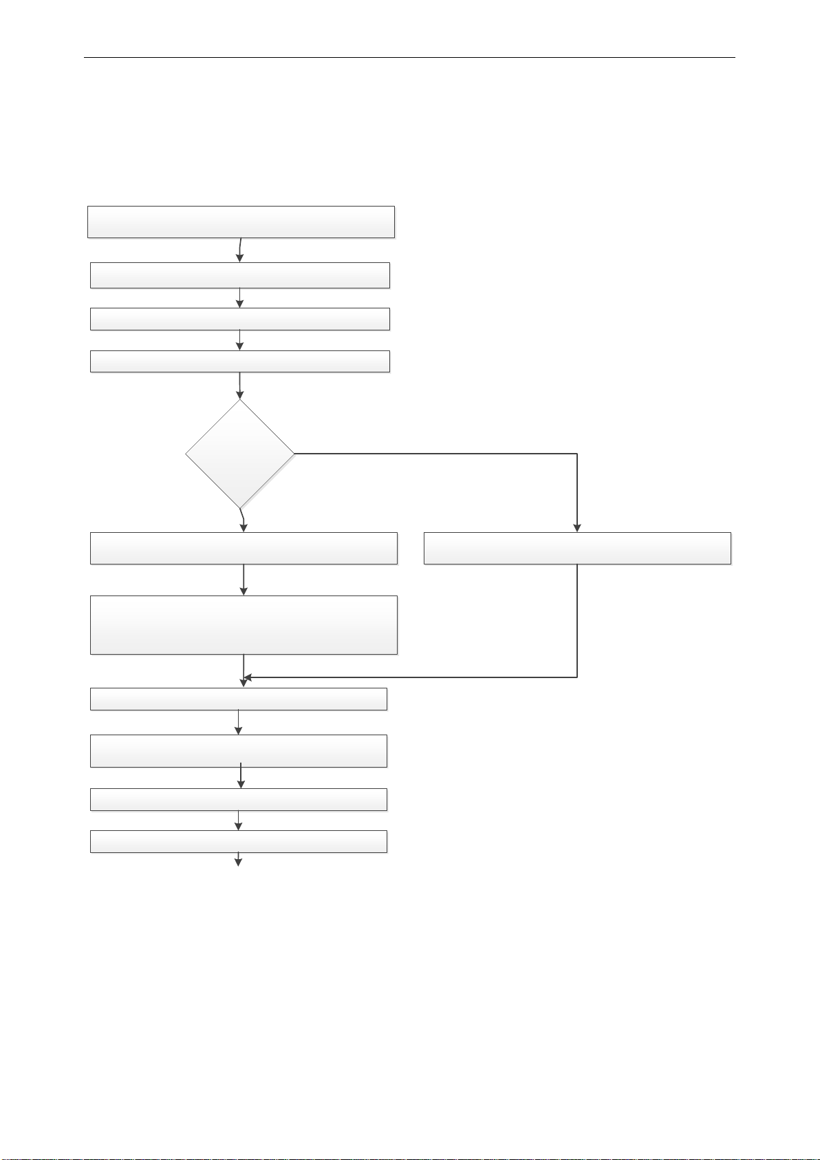
Easy commissioning tips for Mechanical Brake Control:
The application software makes calculations for parameter setting during the identification run
based on motor nominal parameters, brake mechanical opening delay (P2.15.3) and brake
mechanical closing delay (P2.15.4).
Set Motor Parameters as per Motor name plate – Parameter
group G 2.1
Set Brake opening Delay time – P2.15.3
Set Brake closing Delay time – P2.15.4
Set control place & signals selection for DI/DO & AI through
parameter P2.4.1.x to P2.4.4.x
Set Ramp times through parameter P2.3.x
Set brake resistor parameters P2.6.x
External
Brake Chopper or
AFE ?
Set P2.6.4.3 Brake chopper to
Recomendation is [3] Used when stopped/running
Set P2.6.4.4 Brake Chopper Level:
For 400V Supply: 400*1.35*1.18 = 638V
For 500V Supply: 500*1.35*1.18 = 808V
For 690V Supply: 690*1.35*1.18 = 1100V
No
Yes
Set P2.6.4.3 Brake chopper to [2] External
Set Brake control relay output in P2.15.1 BrakeOpen, Direct
Set Brake feedback input (if used) in P 2.15.2 Brake Feedback
Continue….
Page 12
12 • VACON® apfiff20 crane control
Local contacts: http://drives.danfoss.com/danfoss-drives/local-contacts/
Classified as Public
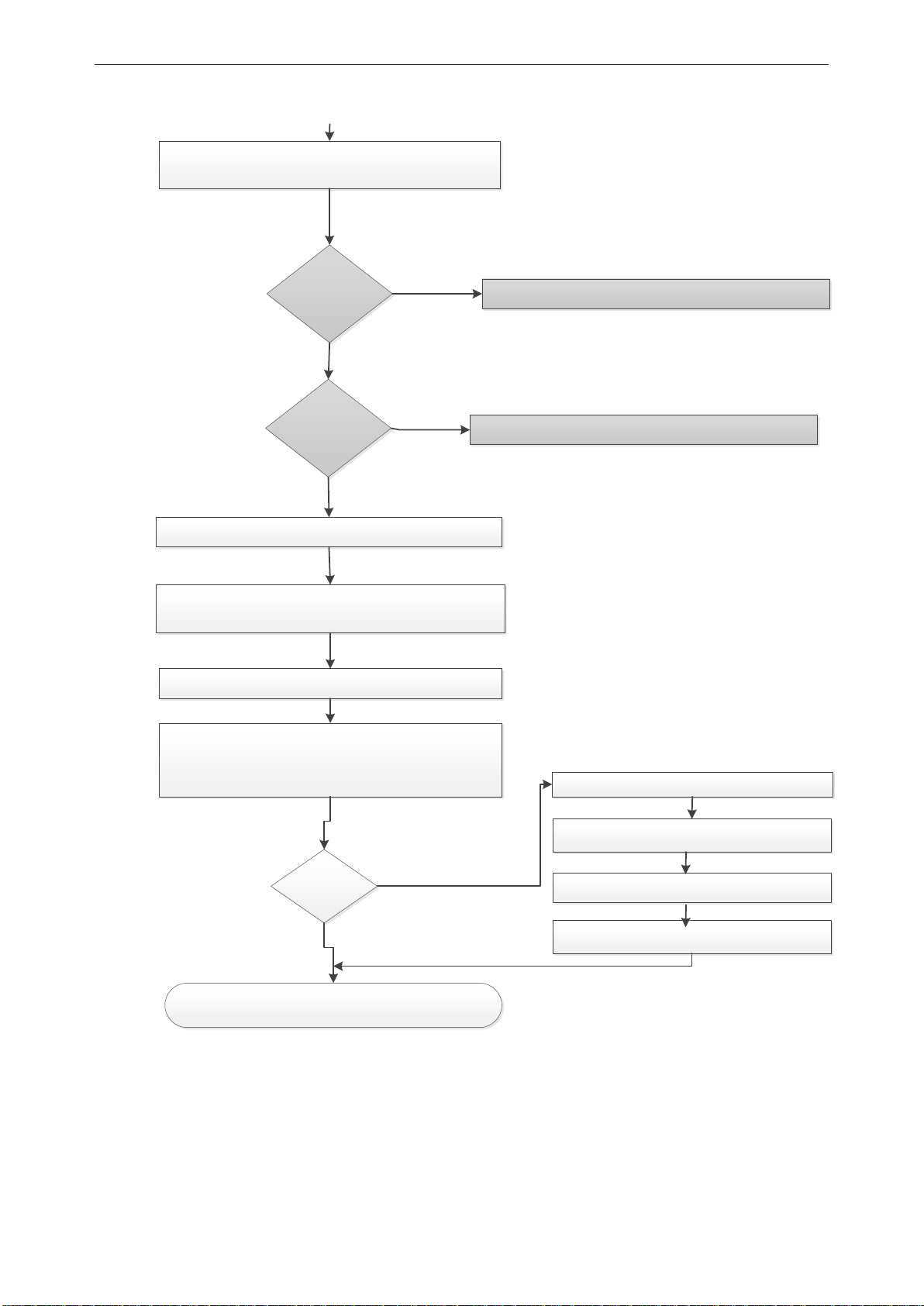
Run in CL?
No
Yes
Perform Motor ID Run in standstill ,P2.1.9 -select 1/ID No
Run. If magnetizing current is known ( calcuated from
cosphi)
Set Encoder parameters in G7.3.x
Set Motor control mode in P2.8.1 to 3/CL speed
control
Set Motor speed and current limits as per application
appropriate P-2.6.xx
VFD is Ready to perform test run on load
Perform Crane ID Run with hoistingoption select with
P2.1.11. for Crane ID run explanation -refer ID run in chapter
basic parameters
Once ID run completed, upload parameters from the drive
ID run Ok
No
Check Motor Name plate and verify with parameters set
Magnetizing
current known?
Perform identification mode 6 (U/F + magnetizing) – refer
chapeter basic parameters
Start Scope Monitor Windowto check if
Encoder 1 freq is equal to motor frequency,
Make Open Loop run without load with monitoring signals
like Brake StatusWord, Motor torque, Motor current,
Frequency Ramp out, Output frequency, Shaft frequency,
Motor Voltage, DC voltage
Check Motor current and torque do not show
abnormal behavior
Page 13
apfiff20 crane control 13 • VACON®
Local contacts: http://drives.danfoss.com/danfoss-drives/local-contacts/
Classified as Public
➢ Roll Back Control for CL
Roll Back function prevents downwards movement of the load when brake is opening and giving
smooth lifting at start. Parameters available in group G2.15.12.x
2.2 Catch Dropping load When Drive is in standby mode (No start command given) and if Mech. Brake failed,
VFD will detects and take over automatically detects, takes over(starts) and bring the
load down to the ground in controlled way. (Operator can only give down command,
forced
lowering, no hoist will be allowed.
This function required closed loop operation.
This function can activate in parameter P2.15.13.5
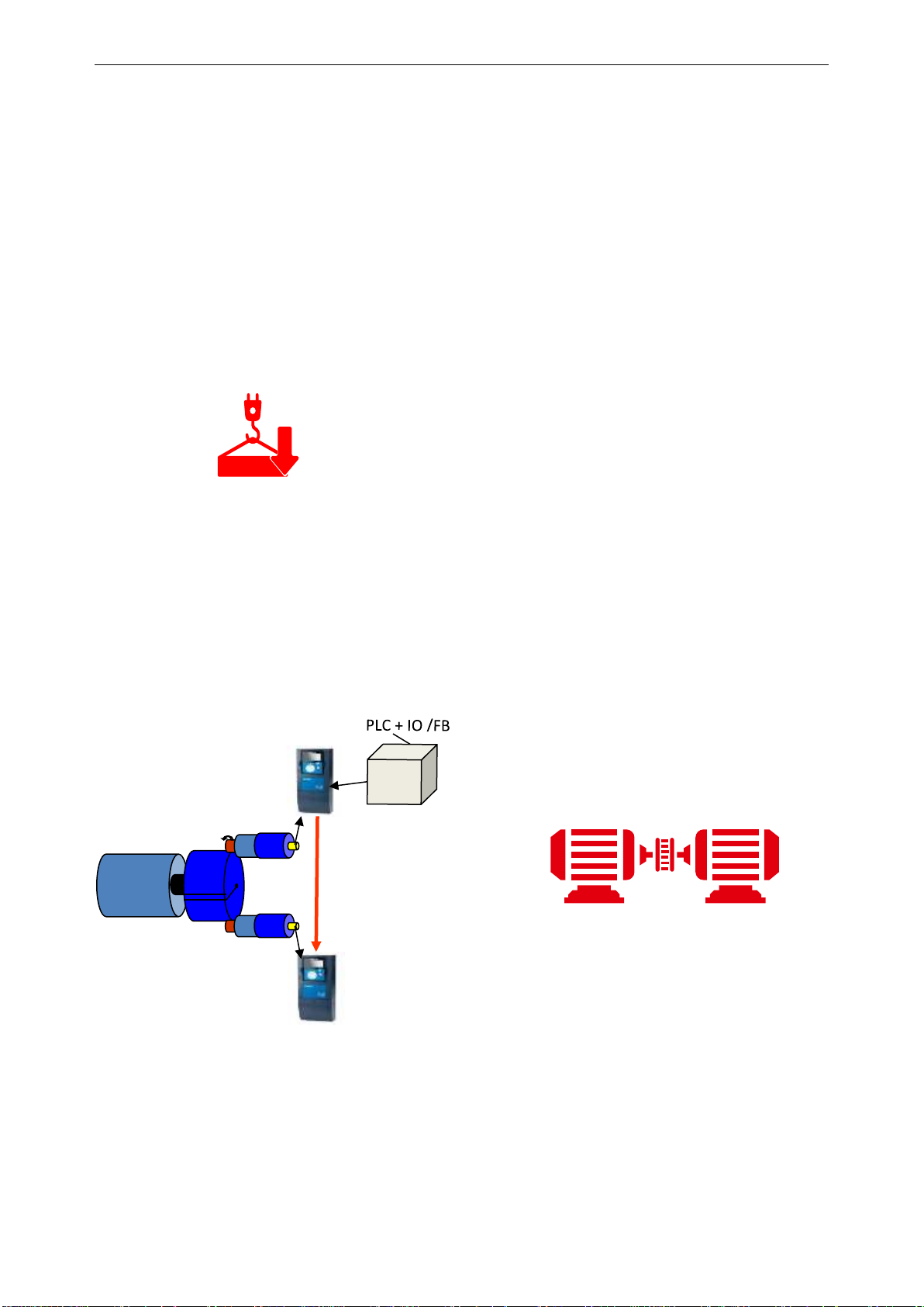
2.3 Tandem Operation for Cranes
➢ Master-Follower (Speed-Torque sharing)
Master-Follower (Speed-Torque sharing) function is mainly used when motor shafts are
coupled to each other for running a common load. In this case, the master will be in
speed control mode and the follower will be in torque control mode.
The external control signals are connected to the master NXP only. The master controls
the follower(s) via a system bus. The master station is typically speed-controlled, and the
other drives follow its torque reference.
Master
Slave
Master-Follower parameters are in group G 2.11.x in chapter 6.11
➢ Tandem Hoist (Shaft Sync)
Tandem Hoist function is used to lift higher capacity load with synchronizing of two axes
at the same time OR more than 01 lifting gear to be connected.
System bus
OPTD2
Torque Sharing
M M
Page 14
14 • VACON® apfiff20 crane control
Local contacts: http://drives.danfoss.com/danfoss-drives/local-contacts/
Classified as Public
Tandem operation helps to monitor and control the position difference of the hooks and
synchronize the movement of each axes.
Shaft synchronization works between master-slave axes through system bus with crane
application software.
Maximum four axes can be synchronized.
Tandem operation communication is enabled with Master-Follower mode P2.11.1
(selection 3 and 4). See chapter 7.11 Master-Follower.
Tandem operation (Shaft Sync) parameters are in group G 2.11.x and G2.18.x in chapter
7.11 and chapter 8.18.
2.4 Speed limit switch for Horizontal Movement Speed limit switch function help to limit speed for horizontal movement when trolley or
travel motion moving towards end direction. External sensors for forward and reverse
direction will connect to Digital inputs of VFD. Forward and reverse speed can be set
independently. Parameters are in group G 2.2.12.x
2.5 Anti-Sway
Typically, overhead cranes are used in manufacturing or maintenance processes where
productivity and safety are considered the most important requirements. Swinging of the load
during the crane’s movement is a natural phenomenon as load is suspended from a gripping
device by cables and acts as a pendulum device.
NXP offers an integrated sensorless Anti-Sway control, where there is no need for encoders or
communication with a hoist drive. The Anti-Sway feature is to be used in trolley and travel
motion only.
The Anti-Sway function is license protected. Users need to buy a license key from a Danfoss
supplier to make the Anti-Sway function effective. License key status can be checked and
verified in monitoring parameter V1.31.2.
To eliminate sway, two different methods are available in Crane application software. User
needs to set either Average Swinging Period or Maximum Rope length.
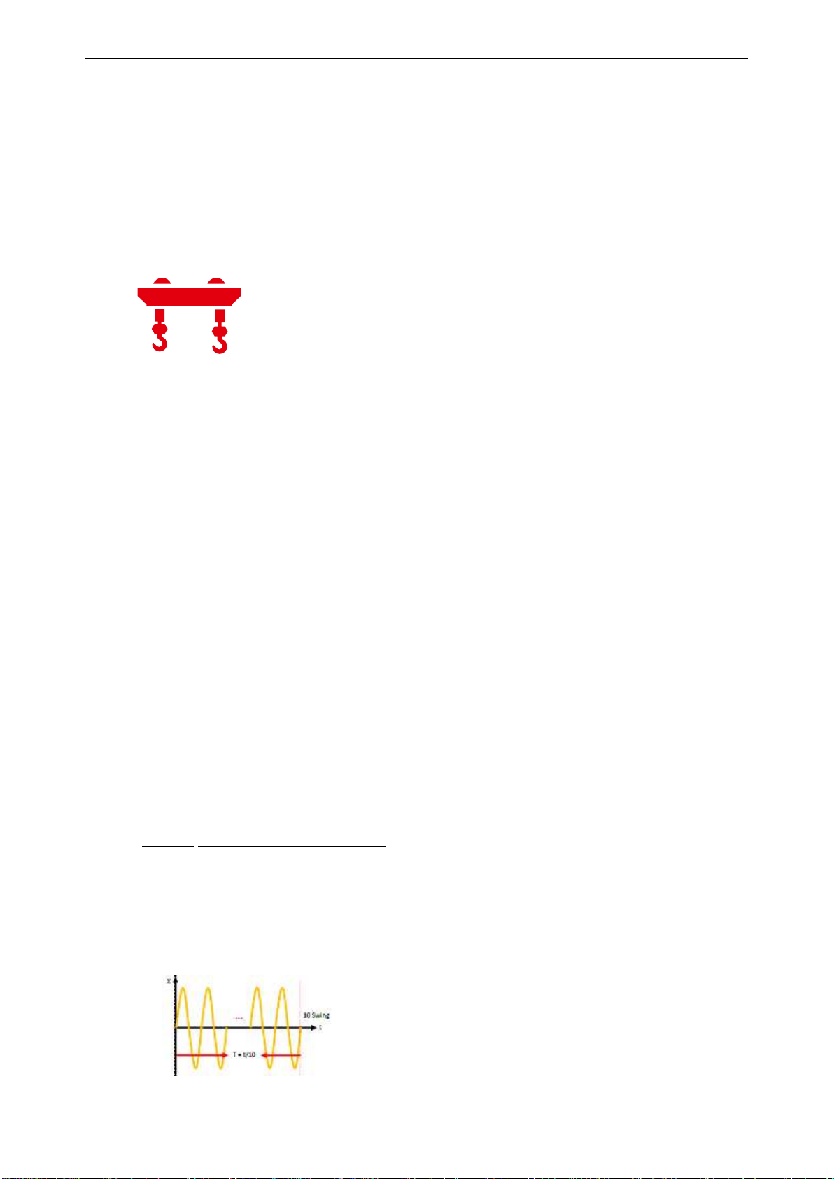
How to calculate swinging period
• Lower the hook to the lowest practical position. There is no need to connect load on the
hook.
• Run the crane with full speed and give stop command.
• Measure the duration of 5–10 swings (back and forth) and calculate the swinging period.
• Enter the swinging period into parameters.
Page 15

apfiff20 crane control 15 • VACON®
Local contacts: http://drives.danfoss.com/danfoss-drives/local-contacts/
Classified as Public
Anti-Sway parameters are in group 2.21.x. Refer to group 2.21.x for different
modes for Anti-Sway with swinging period method.
Rope Length
Maximum rope length (in cm), to be entered in P 2.21.4. From drum to hook touch
down to the ground or just above.
NOTE: If swinging period method is to be used, then Rope Length parameter is to be kept
“ZERO”. If the value for Rope Length is other than zero, then the swinging period method will not
work. With Rope Length method, only “Mode 1” will work effectively.
Anti-Sway parameters are in group P2.21.x. See chapter 6.20 and chapter 7.21 for more details.
2.6 Speed Optimization (Power dependant speed control)
Speed optimizing function limits speed directly to requested power(kW) level. There are different
settings for forward limit speed and reverse limit speed. This function can activate in parameters
G2.6.3.7 and G2.6.3.8.
2.7 Bumpless transfer from closed loop to sensorless control
For closed loop operation, in case of encoder failure, VFD will switch to sensorless
mode with last speed recorded before encoder failure and display “Encoder loss warning”. It will
be Bump less transfer because customer will not see any jerk, speed variation during
changeover from closed loop to sensorless mode and allow them to run in sensorless mode
without any interruption in process. It is Customer responsibility to take safety of crane
movement in account while running in sensorless mode.
This function can activate in parameter P2.12.12.1.
2.8 Shock Load Prevention
Shock Load function enables smooth load pick-up until the load is lifted to air. This protects the
crane from extra stress caused by sudden load change detected by hoist drum and rope at
higher speed.
With Shock Load Prevention, the hoist drive monitors the load. If it is lifted too fast, the hoisting
speed will reduce with predefined “Shock load ref” until “Shock load time” has elapsed.
Shock Load and Slack Rope parameters are in group P2.13.14.x. See chapter 6.3.4 and chapter
7.3.2 for more details.
Page 16

16 • VACON® apfiff20 crane control
Local contacts: http://drives.danfoss.com/danfoss-drives/local-contacts/
Classified as Public
2.9 Slack Rope Prevention
When the load or hook is approaching the ground, it will generate slack at the rope, which could
damage the rope. The rope could also jump out of the rope guides when the load or hook
touches the ground at high speed.
Slack Rope protection mode can be activated through parameter P2.3.14.1. While lowering the
hook load, drive will activate “Zero speed Reference” when actual torque drops below the “Load
off the hook”.
2.10 Integrated functional safety
To activate integrated functional safety features in compliance with SIL3/”Ple”, an advanced
safety option board is required to be installed in C or D slot. There are three types of safety
option boards available (OPTBL, OPTBM and OPTBN), and they can be selected according to
application requirements. See VACON® Advanced Functional Safety Operating Guide for more
details.
Crane application supports Stop Function (STO, SQS, SS1 and SS2 ) and Speed Limit Function
(SLS, SSR and SDI). Functional safety parameters can be activated in parameter group
P2.20.x. See chapter 6.19 and chapter 7.20 for more details.
2.11 Load Estimation
Hoist drive will estimate load on the hook to protect the crane against overload mode. This
means that when the drive detects overload it gives an alarm and stops the crane.
To calculate actual load, hoist mechanical parameters are required to be set in group P2.19.x.
It is important to know that actual load measurement is based on hoist mechanical parameters.
Therefore if the values have not been correctly entered, the drive will not show an accurate
value.
See chapter 6.18 and chapter 7.19 for more details.
Page 17
apfiff20 crane control 17 • VACON®
Local contacts: http://drives.danfoss.com/danfoss-drives/local-contacts/
Classified as Public
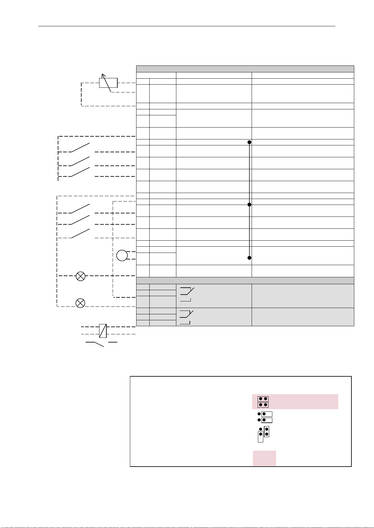
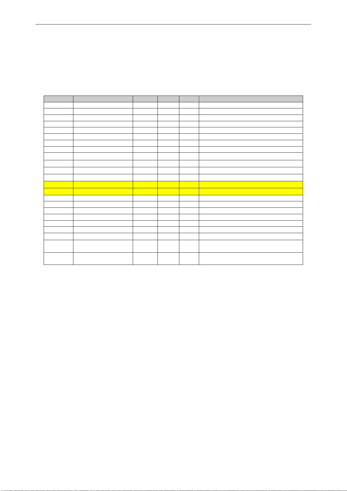
3. CONTROL I/O
NXOPTA1
Terminal
Signal
Description
1
+10V
ref
Reference voltage output
Voltage for potentiometer, etc.
2
AI1+
Analogue input 1.
Range 0-10V, Ri = 200
Range 0-20 mA Ri = 250
Analogue input 1 frequency reference.
Input range selected by jumpers.
Default range: Voltage 0 – 10 V
3
AI1-
I/O Ground
Ground for reference and controls
4
AI2+
Analogue input 2.
Range 0-10V, Ri = 200
Range 0-20 mA Ri = 250
Analogue input 2 frequency reference
Input range selected by jumpers.
Default range: Current 0 – 20 mA
5
AI2-
6
+24V
Control voltage output
Voltage for switches, etc. max 0.1 A
7
GND
I/O ground
Ground for reference and controls
8
DIN1
Programmable G2.2.7
No function defined at default
9
DIN2
Programmable G2.2.7
No function defined at default
10
DIN3
Programmable G2.2.7
No function defined at default
11
CMA
Common for DIN 1—DIN 3
Connect to GND or +24V
12
+24V
Control voltage output
Voltage for switches (see #6)
13
GND
I/O ground
Ground for reference and controls
14
DIN4
Programmable G2.2.7
No function defined at default
15
DIN5
Programmable G2.2.7
No function defined at default
16
DIN6
Programmable G2.2.7
No function defined at default
17
CMB
Common for DIN4—DIN6
Connect to GND or +24V
18
AOA1+
Analogue output 1
Programmable P2.3.1.2
Output range selected by jumpers.
Range 0—20 mA. RL, max. 500
Range 0—10 V. RL > 1k
19
AOA1-
20
DOA1
Digital output
Programmable
Open collector, I50mA, U48 VDC
NXOPTA2
21
RO1
Relay output 1
Programmable G2.3.3
Switching capacity
24 VCD / 8 A
250 VAC / 8 A
125 VDC / 0.4 A
22
RO1
23
RO1
24
RO2
Relay output 2
Programmable G2.3.3
Programmable
No function defined at default
25
RO2
26
RO2
Table 3-1. Brake Control application default I/O configuration and
connection example.
Note: See User Manual, chapter Control Connections, for hardware specification and
configuration.
Note: See jumper selections below.
More information in VACON® NX
User Manual.
220
VAC
Jumper block X3:
CMA and CMB grounding
CMB connected to GND
CMA connected to GND
CMB isolated from GND
CMA isolated from GND
CMB and CMA
internally connected together,
isolated from GND
= Factory default
Reference potentiometer,
1…10 k
mA
Page 18
18 • VACON® apfiff20 crane control
Local contacts: http://drives.danfoss.com/danfoss-drives/local-contacts/
Classified as Public
4. “TERMINAL TO FUNCTION” (TTF) PROGRAMMING PRINCIPLE
The programming principle of the input and output signals in the Multipurpose Control
Application NXP as well as in the Pump and Fan Control Application (and partly in the other
applications) is different compared to the conventional method used in other VACON® NX
applications.
In the conventional programming method, Function to Terminal Programming Method (FTT), you
have a fixed input or output that you define a certain function for. The applications mentioned
above, however, use the Terminal to Function Programming method (TTF) in which the
programming process is carried out the other way round: Functions appear as parameters which
the operator defines a certain input/output for. See Warning on page 19.
4.1 Defining an input/output for a certain function on keypad
Connecting a certain input or output with a certain function (parameter) is done by giving the
parameter an appropriate value. The value is formed of the Board slot on the VACON® NX
control board (see VACON® NX User Manual) and the respective signal number, see below.
Function name
Slot Terminal number
Terminal type
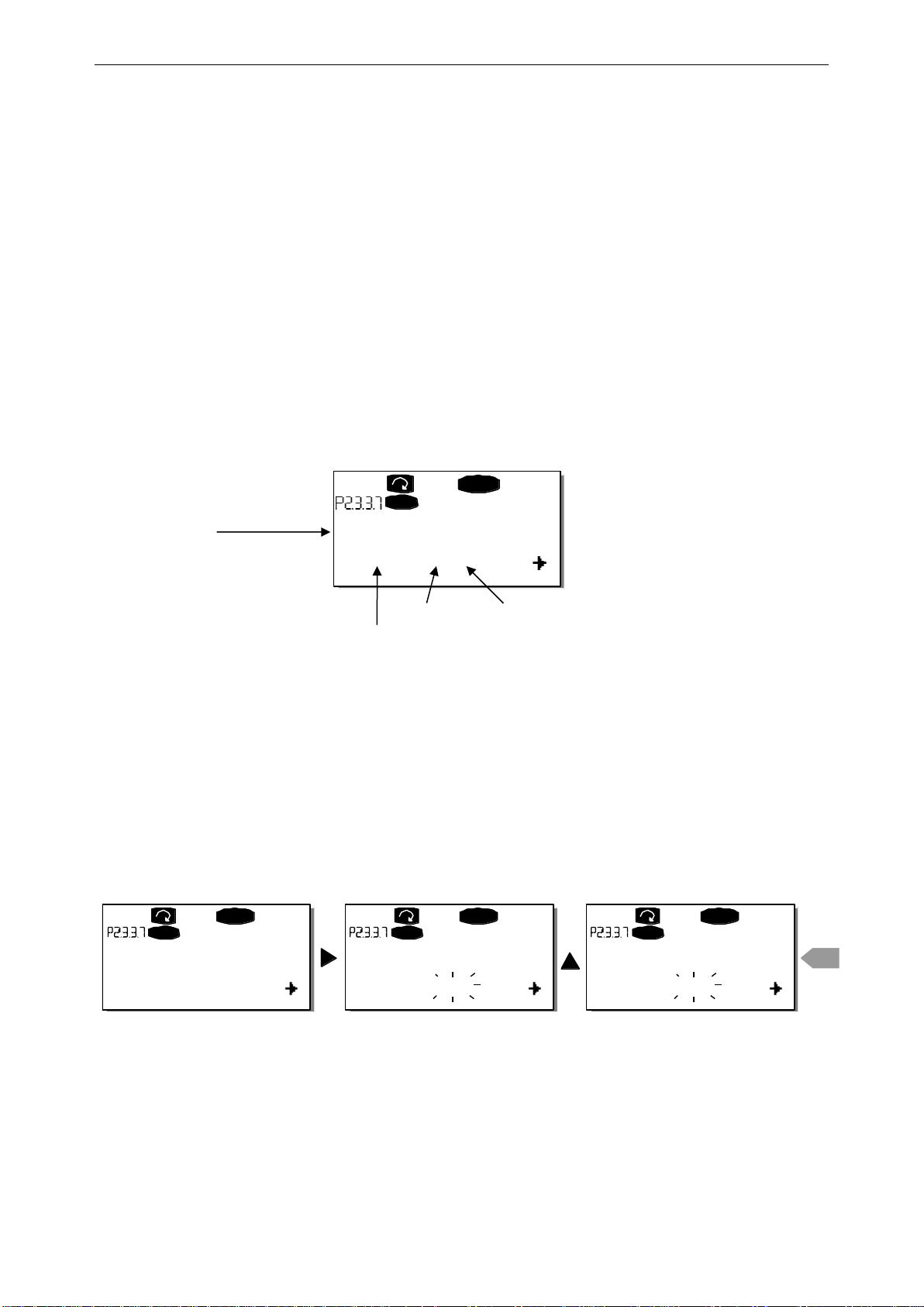
Example: You want to connect the digital output function Reference fault/warning (parameter
2.3.3.7) to the digital output DO1 on the basic board NXOPTA1 (see VACON® NX User Manual).
First find the parameter 2.3.3.7 on the keypad. Press the Menu button right once to enter the edit
mode. On the value line, you will see the terminal type on the left (DigIN, DigOUT, An.IN,
An.OUT) and on the right, the present input/output the function is connected to (B.3, A.2 etc.), or
if not connected, a value (0.#).
When the value is blinking, hold down the Browser button up or down to find the desired board
slot and signal number. The program will scroll the board slots starting from 0 and proceeding
from A to E and the I/O selection from 1 to 10.
Once you have set the desired value, press the Enter button once to confirm the change.
READY
I/Oterm
DigOUT:B.1
AI Ref Faul/Warn
READY
I/Oterm
DigOUT:0.0
READY
I/Oterm
DigOUT:0.0
READY
I/Oterm
DigOUT:B.1
enter
AI Ref Faul/Warn AI Ref Faul/Warn AI Ref Faul/Warn
Page 19
apfiff20 crane control 19 • VACON®
Local contacts: http://drives.danfoss.com/danfoss-drives/local-contacts/
Classified as Public
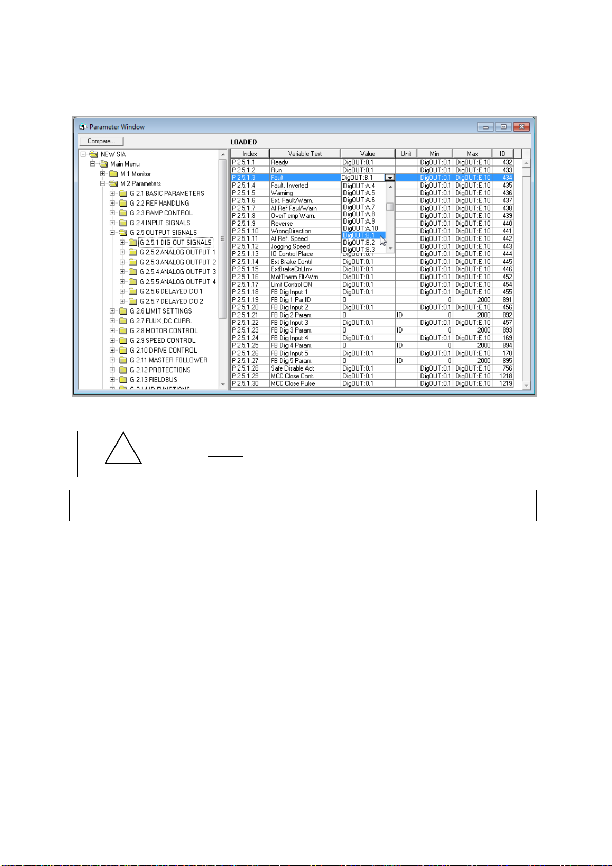
4.2 Defining a terminal for a certain function with NCDrive programming tool
If you use the NCDrive Programming Tool for parametrizing you will have to establish the
connection between the function and input/output in the same way as with the control panel. Just
pick the address code from the drop-down menu in the Value column (see the Figure below).
Figure 4-1. Screenshot of NCDrive programming tool; Entering the address code
Be ABSOLUTELY sure not to connect two functions to one and
same output in order to avoid function overruns and to ensure
flawless operation.
!
WARNING
Note: The inputs, unlike the outputs, cannot be changed in RUN state.
Page 20

20 • VACON® apfiff20 crane control
Local contacts: http://drives.danfoss.com/danfoss-drives/local-contacts/
Classified as Public
4.3 Defining unused inputs/outputs
All unused inputs and outputs must be given the board slot value 0 and the terminal number
value 1. The value 0.1 is also the default value for most of the functions. However, if you want to
use the values of a digital input signal for e.g. testing purposes only, you can set the board
slot value to 0 and the terminal number to any number between 2…10 to place the input to a
TRUE state. In other words, the value 1 corresponds to 'open contact' and values 2 to 10 to
'closed contact'.
In case of analogue inputs, giving the value 1 for the terminal number corresponds to 0% signal
level, value 2 corresponds to 20%, value 3 to 30% and so on. Giving value 10 for the terminal
number corresponds to 100% signal level.
Page 21

apfiff20 crane control 21 • VACON®
Local contacts: http://drives.danfoss.com/danfoss-drives/local-contacts/
Classified as Public
5. CRANE CONTROL APPLICATION – MONITORING VALUES
On the next pages you will find the lists of parameters within the respective parameter groups.
The parameter descriptions are given on pages 96 to 259. The parameter description includes
more than is available in this application, see parameter list for parameters that are available in
this application.
Column explanations:
Code = Location indication on the keypad; Shows the operator the present parameter
number
Parameter = Name of parameter
Min = Minimum value of parameter
Max = Maximum value of parameter
Unit = Unit of parameter value; given if available
Default = Value preset by factory
Cust = Customer’s own setting
ID = ID number of the parameter
_____ = On parameter code: Parameter value can only be changed after the FC has
been stopped.
_____ = Apply the Terminal to Function method (TTF) to these parameters (see chapter
4)
_____ = Monitoring value is possible to control from fieldbus by ID number
The manual presents signals that are not normally visible for monitoring. i.e. is not a parameter
or standard monitoring signal. These signals are presented with [Letter]. e.g.
[FW]MotorRegulatorStatus
[V] Normal monitoring signal
[P] Normal parameter in application
[FW] Firmware signal, Can be monitored with NCDrive when signal type is selected Firmware
[A] Application signal, can be monitored with NCDrive when signal type is selected
Application
[R] Reference type parameter on keypad
[F] Function. Signal is received as a output of function.
[DI] Digital input signal
Page 22
22 • VACON® apfiff20 crane control
Local contacts: http://drives.danfoss.com/danfoss-drives/local-contacts/
Classified as Public
5.1 Monitoring values
The monitoring values are the actual values of parameters and signals as well as statuses and
measurements.
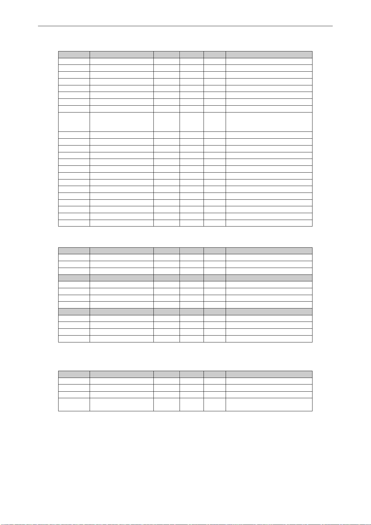
5.1.1 Monitoring values 1
Code
Parameter
Unit
Form.
ID
Description
V1.1
Output frequency
Hz
#,##
1
Output frequency to motor
V1.2
Frequency reference
Hz
#,##
25
Frequency reference to motor control
V1.3
Motor speed
rpm # 2
Motor speed in rpm
V1.4
Motor current
A
Varies
3
1 s linear filtering
V1.5
Motor torque
%
#,#
4
In % of Motor nominal torque
V1.6
Motor Power
%
#,#
5
V1.7
Motor voltage
V
#,#
6
Calculated motor voltage
V1.8
DC link voltage
V # 7
Measured DC voltage, filtered.
V1.9
Unit temperature
C
# 8 Heatsink temperature
V1.10
Motor temperature
%
#
9
Calculated motor temperature
V1.11
Analogue input 1
%
#,##
13
AI1, unfiltered.
V1.12
Analogue input 2
%
#,##
14
AI2, unfiltered.
V1.13
Analogue input 3
%
#,##
27
AI3, unfiltered.
V1.14
Analogue input 4
%
#,##
28
AI4, unfiltered.
V1.15
Analogue Out 1
%
#,##
26
AO1
V1.16
Analogue Out 2
%
#,##
50
AO2
V1.17
Analogue Out 3
%
#,##
51
AO3
V1.18
Analogue Out 4
%
#,##
1526 V1.19
DIN1, DIN2, DIN3
15
Digital input statuses
V1.20
DIN4, DIN5, DIN6
16
Digital input statuses
V1.21
Torque reference
%
#,#
18
Used Torque Reference
V1.22
PT-100 Temperature
Cº
#,#
42
Highest temperature of OPTB8 board. 4 s
filtering.
G1.23
Multimonitoring items
Displays three selectable monitoring
values
Table 5-1. Monitoring values
Page 23

apfiff20 crane control 23 • VACON®
Local contacts: http://drives.danfoss.com/danfoss-drives/local-contacts/
Classified as Public
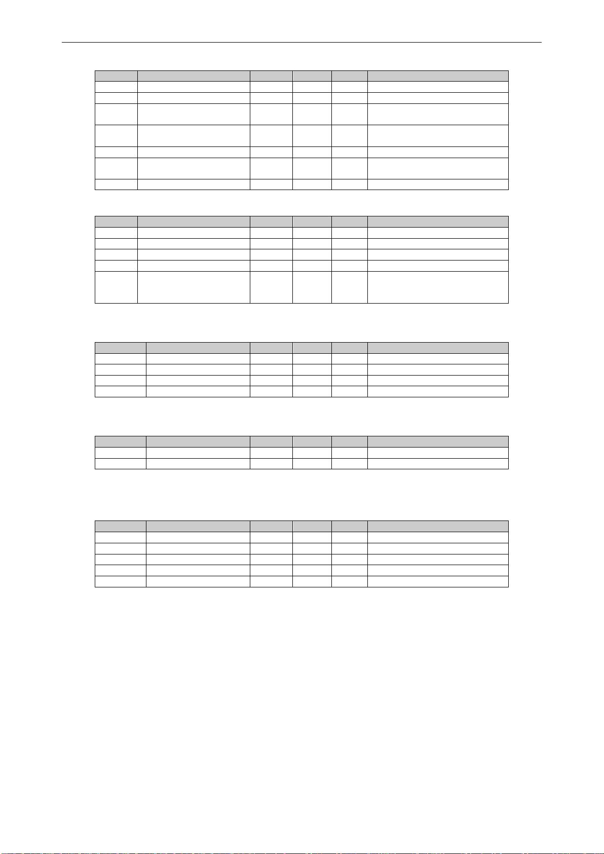
5.1.2 Monitoring values 2
Code
Parameter
Unit
Form.
ID
Description
V1.24.1
Current
A
Varies
1113
Unfiltered motor current
V1.24.2
Torque
%
#,#
1125
Unfiltered motor torque
V1.24.3
DC Voltage
V # 44
Unfiltered DC link voltage
V1.24.4
Status Word 1
(Application)
43
V1.24.5
Encoder 1 Frequency
Hz
#,##
1124
Unfiltered
V1.24.6
Output Power
kw
Varies
1508
Unfiltered electrical power
V1.24.7
Measured temperature
1
Cº
#,#
50
4 s filtering.
V1.24.8
Measured temperature
2
Cº
#,#
51
4 s filtering.
V1.24.9
Measured temperature
3
Cº
#,#
52
4 s filtering.
V1.24.10
Measured temperature
4
Cº
#,#
69
4 s filtering.
V1.24.11
Measured temperature
5
Cº
#,#
70
4 s filtering.
V1.24.12
Measured temperature
6
Cº
#,#
71
4 s filtering.
V1.24.13
ABS Encoder
Revolutions
r
#
55
V1.24.14
ABS Encoder Position
#
54
V1.24.15
Step response
Hz
#,##
1132
V1.24.16
CosPhiiActual
#,###
68 V1.24.17
Flux Current
%
#,#
72 V1.24.18
Regulator Status
77 V1.24.19
Frequency Delta
1847
V1.24.20
Rotor Flux
%
#,#
1158
V1.24.21
DataLogger Trigger
Word
97
V1.24.22
Ident Failure Code
98 V1.24.23
Non Ready Causes
1608
V1.24.24
Prevent MC Ready
1609
Table 5-2. Monitoring values 2
Page 24
24 • VACON® apfiff20 crane control
Local contacts: http://drives.danfoss.com/danfoss-drives/local-contacts/
Classified as Public
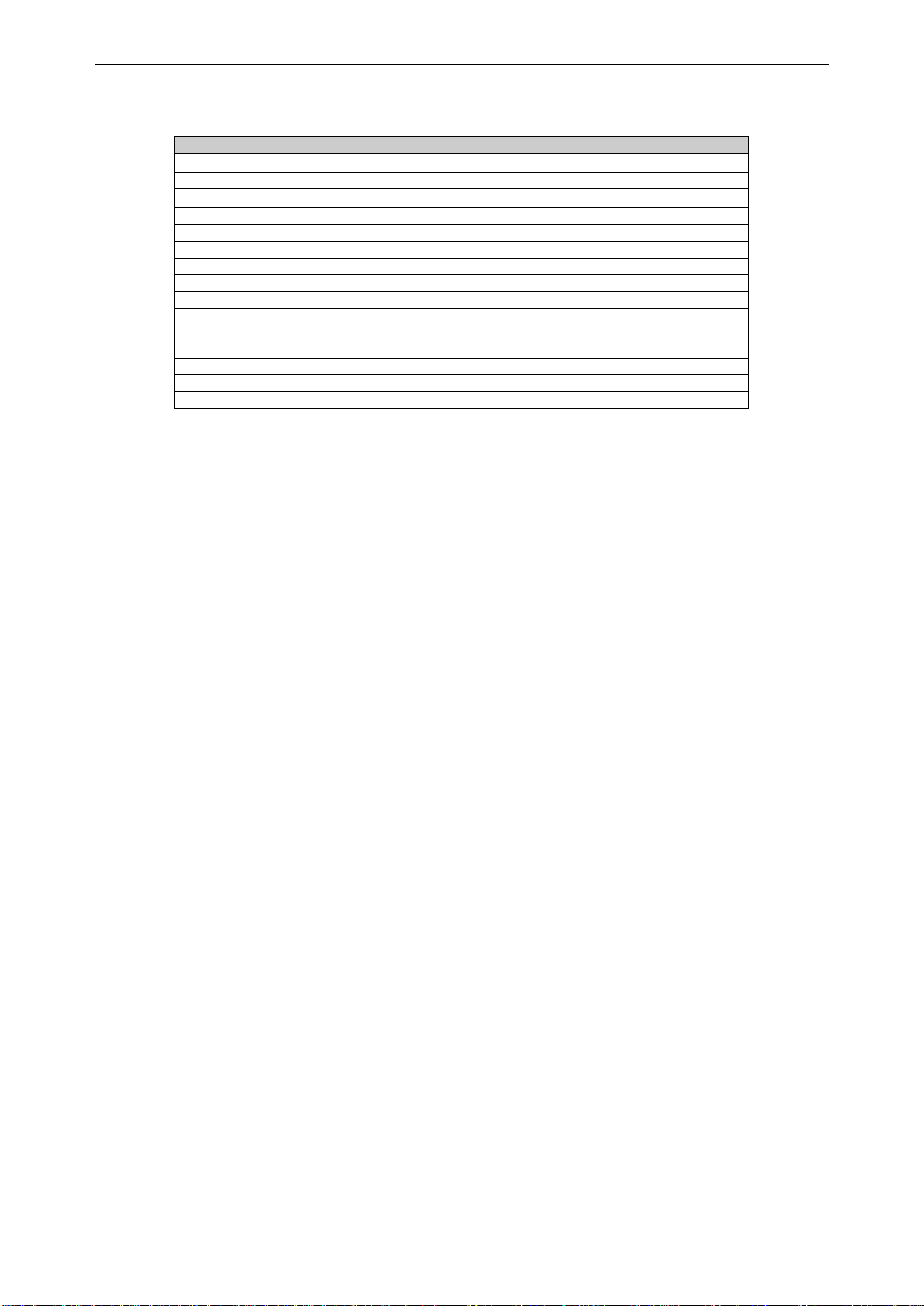
5.1.3 Fieldbus Monitoring values
Code
Parameter
Unit
Form.
ID
Description
V1.25.1
FB Control Word
1160
V1.25.2
FB Speed Reference
875 V1.25.3
FB Status Word
65 V1.25.4
FB Actual Speed
865 V1.25.5
FB Torque Reference
%
#,#
1140
Default Control of FB PD 1
V1.25.6
FB Limit Scaling
%
#,##
46
Default Control of FB PD 2
V1.25.7
FB Adjust Reference
%
#,##
47
Default Control of FB PD 3
V1.25.8
FB Analog Output
%
#,##
48
Default Control of FB PD 4
V1.25.9
FB Motor Current
A
#,#
45
Motor current (drive
independent) given with one
decimal point
V1.25.10
Fault Word 1
1172
V1.25.11
Fault Word 2
1173
V1.25.12
Warning Word 1
1174
V1.25.13
AuxStatusWord
1163
V1.25.14
Last Active Fault
37 V1.25.15
AuxControlWord
1161
V1.25.16
Din Status Word
56
V1.25.17
Din Status Word 2
57 V1.25.18
MC Status
64 V1.25.19
Last Active Warning
74 V1.25.20
Encoder Rounds
1170
V1.25.21
Encoder Angle
1169
V1.25.22
Fault Word 10
1202
V1.25.23
Warning Word 10
1269
Table 5-3. Fieldbus Monitoring values
5.1.4 Master/Follower Monitoring values
Code
Parameter
Unit
Form.
ID
Description
V1.26.1
SB System Status
1601
V1.26.2
Total Current
A
#,#
80
Sum current of all drives (DS)
V1.26.3
Master Control Word
93 Code
Parameter
Unit ID
Description
V1.26.4.1
Motor Current D1
A 1616
V1.26.4.2
Motor Current D2
A 1605
V1.26.4.3
Motor Current D3
A 1606
V1.26.4.4
Motor Current D4
A 1607 Code
Parameter
Unit ID
Description
V1.26.4.1
Status Word D1
1615
V1.26.4.2
Status Word D2
1602
V1.26.4.3
Status Word D3
1603
V1.26.4.4
Status Word D4
1604
Table 5-4. Master/Follower Monitoring values
5.1.5 PI Control Monitoring values
Code
Parameter
Unit
Form.
ID
Description
V1.27.1
PI Reference
20
Used PI Reference
V1.27.2
PI Actual Value
21
PI Actual value
V1.27.3
PI Output
23
PI Output before scaling
V1.27.4
PI Output Scaled
1807
Scaled PI Output
This is used for ID connection
Page 25
apfiff20 crane control 25 • VACON®
Local contacts: http://drives.danfoss.com/danfoss-drives/local-contacts/
Classified as Public
5.1.6 Frequency Chain
Code
Parameter
Unit
Form.
ID
Description
V1.28.1
Frequency Reference 1
Hz
1126
V1.28.2
Frequency Reference 2
Hz
1127
V1.28.3
Frequency reference
Hz
#,##
25
Frequency reference to motor
control
V1.28.4
Frequency Reference
Actual
Hz
1128
V1.28.5
Frequency Ramp Out
Hz
1129
V1.28.6
Frequency Reference
Final
Hz
1131
V1.28.7
Encoder Frequency
Hz
1164
5.1.7 Torque Chain
Code
Parameter
Unit
Form.
ID
Description
V1.29.1
Torque Reference
% 18 V1.29.2
Torque Reference 3
% 1144
V1.29.3
Torque Ref Final
% 1145
V1.29.4
Speed Control Out
% 1134
V1.29.5
Torque Reference
Actual
% 1180
Final torque reference from
speed control and/or torque
control
5.1.8 Brake Control
Code
Parameter
Unit
Form.
ID
Description
V1.30.1
Brake Status Word
89 V1.30.2
Load Estimation
kg
#
1914
V1.30.3
Load Estimation 100
kg
#,##
1913
V1.30.4
RopeLengthInUse
cm
#
1915
5.1.9 Motion
Code
Parameter
Unit
Form.
ID
Description
V1.31.1
Serial Number Key
V1.31.2
License Status
5.1.10 Shaft Synch
Code
Parameter
Unit
Form.
ID
Description
V1.32.1
Master Rotations
1820
V1.32.2
Own Rotations
1821
V1.32.3
Control Out
1822
V1.32.4
Rotation Error
1823
V1.32.5
Position Ref
1825
Page 26
26 • VACON® apfiff20 crane control
Local contacts: http://drives.danfoss.com/danfoss-drives/local-contacts/
Classified as Public
5.1.11 Functional Safety Monitoring
Code
Signal
Unit
ID
Description
V1.33.1
Safety App Status
1653
V1.33.2
Integrity Level
1640
V1.33.3
Acknowledge Mode
1641
V1.33.4
Safety Encoder Speed
rpm
1642
V1.33.5
Ramp Selection
1643
V1.33.6
Function Reached
1644
V1.33.7
Request DIN
1645
V1.33.8
Request PLC
1646
V1.33.9
Function In Use
1647
V1.33.10
Safety Status Word
1648
V1.33.11
Safety General Status
Word
1649
V1.33.12
Safety Status
1650
V1.33.13
Safety Zero Speed
1651
V1.33.14
SBC Speed
rpm
1652
Page 27

apfiff20 crane control 27 • VACON®
Local contacts: http://drives.danfoss.com/danfoss-drives/local-contacts/
Classified as Public
5.2 Monitoring Values description
5.2.1 Monitoring values
V1.1 Output frequency [#,## Hz] ID1
Output frequency to motor, updated at 10 ms time level.
V1.2 Frequency reference [#,## Hz] ID 25
Frequency reference to motor control, after speed share function, updated at 1 ms
time level.
V1.3 Motor speed [ # rpm] ID 2
Motor speed in rpm
V1.4 Motor current [A] ID 3
Measured motor RMS current
Current scaling in different size of units
Note: ID45, usually in Process data OUT 3 is scaled to be with one decimal always.
Voltage
Size
Scale
208 – 240 Vac
NX0001 – NX0011
100 – 0.01A
208 – 240 Vac
NX0012 – NX0420
10 – 0.1A
208 – 240 Vac
NX0530
1 – 1A
380 – 500 Vac
NX0003 – NX0007
100 – 0.01A
380 – 500 Vac
NX0009 – NX0300
10 – 0.1A
380 – 500 Vac
NX0385 – NX2643
1 – 1A
525 – 690 Vac
NX0004 – NX0013
100 – 0.01A
525 – 690 Vac
NX0018 – NX0261
10 – 0.1A
525 – 690 Vac
NX0325 – NX1500
1 – 1A
V1.5 Motor torque % ID 4
In % of Motor nominal torque
V1.6 Motor Power % ID 5
Calculated motor power
V1.7 Motor voltage V ID 6
Calculated motor voltage
V1.8 DC link voltage V ID 7
Measured DC voltage, filtered.
V1.9 Unit temperature C ID 8
Heatsink temperature
V1.10 Motor temperature % ID 9
Calculated motor temperature
105 % is tripping limit if response is fault.
Page 28

28 • VACON® apfiff20 crane control
Local contacts: http://drives.danfoss.com/danfoss-drives/local-contacts/
Classified as Public
V1.11 Analogue input 1 % ID 13
V1.12 Analogue input 2 % ID 14
Unfiltered analogue input level.
0% = 0 mA / 0 V, -100% = -10 V, 100% = 20 mA / 10 V.
Monitoring scaling is determined by the option board parameter.
V1.13 Analogue input 3 % ID 27
V1.14 Analogue input 4 % ID 28
It is possible to adjust this input value from fieldbus when the input terminal selection
is 0.1. This way it is possible to adjust the free analogue input from fieldbus and have
all analogue input functions available for fieldbus process data.
V1.15 Analogue Out 1 % ID 26
V1.16 Analogue Out 2 % ID 50
V1.17 Analogue Out 3 % ID 51
V1.18 Analogue Out 4 % ID 1526
Analogue Output value 0% = 0 mA / 0 V, 100% = 20 mA / 10 V
V1.19 DIN1, DIN2, DIN3 ID 15
V1.20 DIN4, DIN5, DIN6 ID 16
DIN1/DIN2/DIN3 status
DIN4/DIN5/DIN6 status
b0
DIN3
DIN6
b1
DIN2
DIN5
b2
DIN1
DIN4
V1.21 Torque reference % ID 18
Torque reference value before load share.
V1.22 PT-100 Temperature Cº ID 42
Highest temperature of OPTB8 board. 4 s filtering.
Page 29

apfiff20 crane control 29 • VACON®
Local contacts: http://drives.danfoss.com/danfoss-drives/local-contacts/
Classified as Public
5.2.2 Monitoring values 2
V1.24.1 Current A ID 1113
Unfiltered motor current, recommended signal for NCDrive monitoring.
V1.24.2 Torque % ID 1125
Unfiltered motor torque, recommended signal for NCDrive monitoring.
V1.24.3 DC Voltage V ID 44
Unfiltered DC link voltage, recommended signal for NCDrive monitoring.
V1.24.4 Application Status Word ID 43
Application Status Word combines different drive statuses to one data word.
Recommended signal for NCDrive monitoring.
Application Status Word ID43
FALSE
TRUE
b0
Flux not ready
Flux ready (>90 %)
b1
Not in Ready state
Ready
b2
Not Running
Running
b3
No Fault
Fault
b4
Direction Forward
Direction Reverse
b5
Emergency Stop Active
Emergency Stop NOT Active
b6
Run Disabled
Run Enable
b7
No Warning
Warning
b8
Power positive
Power negative or Gen torque or current
limit active
b9
b10
b11
No DC Brake
DC Brake is active
b12
No Run Request
Run Request
b13
No Limit Controls Active
Limit control Active
b14
External Brake Control OFF
External Brake Control ON
b15
V1.24.5 Shaft Frequency Hz ID 1124
Encoder frequency after filter. P2.8.4.6 Encoder1FiltTime.
V1.24.6 Output Power [kw] ID1508
Unfiltered electrical drive output power.
Page 30

30 • VACON® apfiff20 crane control
Local contacts: http://drives.danfoss.com/danfoss-drives/local-contacts/
Classified as Public
V1.24.7 Measured temperature 1 Cº ID 50
V1.24.8 Measured temperature 2 Cº ID 51
V1.24.9 Measured temperature 3 Cº ID 52
V1.24.10 Measured temperature 4 Cº ID 69
V1.24.11 Measured temperature 5 Cº ID 70
V1.24.12 Measured temperature 6 Cº ID 71
Separate measurement from two PT100 boards. The signal has 4 s filtering time.
V1.24.13 ABS Encoder Revolutions ID55
Absolute encoder revolution information.
V1.24.14 ABS Encoder Position ID54
Absolute encoder position within one rotation. See encoder manual for scaling.
V1.24.15 Step response Hz ID 1132
Frequency error. Compares ramp output to actual encoder frequency with 0.001 Hz
accuracy. Can be used for speed control tuning in closed loop control.
V1.24.16 CosPhiiActual ID 68
Estimated Cos Phii.
V1.24.17 Flux Current % ID 72
Flux current part or the total current. 100% = Motor Nominal Current.
V1.24.18 Regulator Status ID 77
Regulator status ID77
b0
Motoring Current Regulator Status
b1
Generator Current Regulator Status
b2
Motoring Torque Regulator Status
For CL monitor B0
b3
Generator Torque Regulator Status
For CL monitor B1
b4
Over Voltage Regulator Status
DC Voltage
b5
Under Voltage Regulator Status
DC Voltage
b6
b7
b8
b9
b10
b11
b12
b13
b14
b15
Page 31

apfiff20 crane control 31 • VACON®
Local contacts: http://drives.danfoss.com/danfoss-drives/local-contacts/
Classified as Public
V1.24.19 Frequency Delta ID 1847
Change of Final Frequency Reference in Hz/s.
V1.24.20 Rotor Flux ID1158 “Rotor Flux”
Calculated Rotor flux.
V1.24.21 Data Logger Trigger Word ID 97
Data Logger Trig Word ID97
Function
Comment
b0
Fault Status
Logger is triggered when there is a fault
b1
Warning Status
Logger is triggered when there is a warning
b2
Auto Reset Warning
Logger is triggered when there is a fault that
has been defined to be automatically reset.
This bit can be used to get the first fault
situation.
b3
Fault Status OR Warning Status
B0 OR B1 triggering situation has occurred
b4
Fault Status OR Auto Reset Warning
B0 OR B2 triggering situation has occurred
b5
b6
b7
b8
b9
b10
b11
b12
b13
b14
b15
V1.24.22 Ident Failure Code [Ident Fail. Code] ID 98
Failure code for failed identification:
1 = Current measurement offset
2 = Identification current level
3 = Acceleration time too long
4 = Identification frequency reference not reached
5 = Too low or high magnetization current
6 = Flux curve outside expected levels
7 = PMSM, Encoder zero position
8 = Too low maximum frequency limit
9 = PMSM, encoder zero pulse not found
10 = Ls Identification timeout
11 = Ls Identification current
Page 32

32 • VACON® apfiff20 crane control
Local contacts: http://drives.danfoss.com/danfoss-drives/local-contacts/
Classified as Public
V1.24.23 Non Ready Cause ID 1608
Non Ready Cause ID1608
Signal
b0
Fault is Active
b1
PreventMCReady is set
b2
Charge switch is open
b3
DC Voltage not OK
b4
Power unit state not OK
b5
StartUp Wizard is active
b6
Run Enable is not set
b7
Ready state prevented by STO
b8
b9
b10
b11
b12
b13
b14
b15
V1.24.24 Prevent MC Ready ID 1609
Prevent MC Ready ID1609
Signal
b0
Endat option board (OPTBB, OPTBE) communication is not initialized
after power-up.
b1
Drive sync master has wrong modulator or 1000ms task parameters
are not initialized
b2
Drive sync follower delay is active
b3
Drive sync failure in sw modulator double period mode
b4
Charge switch delay is active
b5
AFE fast run disable through ENC C1 is active
b6
100ms task not executed
b7 b8 b9 b10 b11 b12 b13 b14 b15
Page 33

apfiff20 crane control 33 • VACON®
Local contacts: http://drives.danfoss.com/danfoss-drives/local-contacts/
Classified as Public
5.2.3 FieldBus Monitoring values
V1.25.1 FB Control Word ID1160
Control word used in bypass mode. See P2.13.22 and option board ByPass.
Bit
Description
Value = 0
Value = 1
0
OFF
ON, Reset after Fault or b1 and b2
1
Emergency stop by coast
ON, On normal operation: Keep TRUE
2
Emergency stop by ramp
ON, On normal operation: Keep TRUE
3
STOP REQUEST
RUN REQUST
4
Force ramp to Zero
Enable Ramp,
5
Freeze Ramp
Enable Ramp,
6
Force Ref to Zero
Enable Ramp,
7
No Action
FAULT RESET (0 -> 1)
8
No Action
Inching 1
9
No Action
Inching 2
10
Disable Profibus control
Enable Profibus control
11
Fieldbus DIN1=OFF
Fieldbus DIN1=ON (Watchdog pulse)
12
Fieldbus DIN2=OFF
Fieldbus DIN2=ON
13
Fieldbus DIN3=OFF
Fieldbus DIN3=ON
14
Fieldbus DIN4=OFF
Fieldbus DIN4=ON
15
No Action
No Action
V1.25.2 FB Speed Reference ID875
FB Speed Reference from the fieldbus
V1.25.3 FB Status Word ID65
Profibus type status word. Generated in the application level.
Needs to be selected with P2.14.19 GSW to be used. When needed with profibus
board, operation mode needs to be set to ByPass in option board and with P2.14.22
ProfiBus Mode select: 2 / ProfiDrive.
Bit
Description
Value = 0
Value = 1
0
Not ready to switch on
Ready to switch on
1
Not ready to operate
Ready to operate
2
Not Running
Running
3
No Fault
Fault
4
Coast stop Active
Coast stop not active
5
Quick stop active
Quick stop not active
6
Switch not inhibited
Switch on inhibit
7
No Warning
Warning
8
Speed error
Speed At Reference
9
No FB Control request
FB Control Active
10
Fout < Fmax
Fout > Fmax
11
not used
not used
12
not used
not used
13
not used
not used
14
not used
not used
15
Fieldbus DIN1=OFF
Fieldbus DIN1=ON (Watchdog pulse)
Page 34

34 • VACON® apfiff20 crane control
Local contacts: http://drives.danfoss.com/danfoss-drives/local-contacts/
Classified as Public
V1.25.4 FB Speed Actual ID865
Actual speed value send to fieldbus.
V1.25.5 FB Torque Reference % ID 1140
Torque reference value from fieldbus
Default Control of FB PD 1
V1.25.6 FB Limit Scaling % ID 46
Limit scaling input value from fieldbus.
Default Control of FB PD 2.
V1.25.7 FB Adjust Reference % ID 47
Reference adjustment value from fieldbus.
Default Control of FB PD 3.
V1.25.8 FB Analog Output % ID 48
Fieldbus value to control analogue output.
Default Control of FB PD 4.
V1.25.9 FB Motor Current A ID 45
Motor current (drive independent) given with one decimal point.
V1.25.10 Fault Word 1 ID 1172
Different faults are collected to two words that can be read from fieldbus or with
NCDrive PC software.
Fault Word 1 ID1172
Fault
Comment
b0
Over Current or IGBT
F1, F31, F41
b1
Over Voltage
F2
b2
Under Voltage
F9
b3
Motor Stalled
F15
b4
Earth Fault
F3
b5
Motor Under Load
F17
b6
Drive over temperature
F14
b7
Over Temperature
F16, F56, F29
b8
Input Phase
F10
b9
Brake resistor over temperature
F42
(Not implemented)
b10
Device Changed
F37, F38, F39, F40, F44, F45
(Not implemented)
b11
Keypad or PCControl
F52
b12
FielBus
F53
b13
SystemBus
F59
b14
Slot
F54
b15
4 mA
F50
Page 35
apfiff20 crane control 35 • VACON®
Local contacts: http://drives.danfoss.com/danfoss-drives/local-contacts/
Classified as Public
V1.25.11 Fault Word 2 ID 1173
Fault Word 2 ID1173
Fault
Comment
b0
Output phase
F11
b1
Charge Switch
F5 (Not implemented)
b2
Encoder
F43
b3
Inverter
F4, F7 (Not implemented)
b4
b5
EEPROM
F22 (Not implemented)
b6
External
F51
b7
Brake Chopper
F12 (Not implemented)
b8
Watch Dog
F25 (Not implemented)
b9
IGBT
F31, F41
b10
Brake
F58
b11
Fan Cooling
F32
b12
Application
F35 (Not implemented)
b13
Control fault
F33, F36, F8 (Not implemented)
b14
Main Switch Open
F64 (Not implemented)
b15
V1.25.12 Warning Word 1 ID 1174
Warning Word 1 ID1174
Fault
Comment
b0
Motor stalled
W15
b1
Motor over temperature
W16
b2
Motor under load
W17
b3
Input phase loss
W10
b4
Output phase loss
W11
b5
Safe disable
W30 (Not implemented)
b6
FieldBus communication fault in slot D
W53 (Not implemented)
b7
FieldBus communication fault in slot E
W67 (Not implemented)
b8
Drive over temperature
W14
b9
Analogue input < 4mA
W50
b10
Not used
b11
Emergency stop
W63 (Not implemented)
b12
Run disabled
W62 (Not implemented)
b13
Not used
b14
Mechanical Brake
W58
b15
Not used
Page 36

36 • VACON® apfiff20 crane control
Local contacts: http://drives.danfoss.com/danfoss-drives/local-contacts/
Classified as Public
V1.25.13 AuxStatusWord ID 1163
Aux Status Word ID1163
Fault
Comment
b0
Reserved
Reserved
b1
Window control active and speed outside of
widow
b2
Reserved
Reserved
b3
Reserved
Reserved
b4
Reserved
Reserved
b5
Reserved
Reserved
b6
Reserved
Reserved
b7
No Action
Ext brake is forced open
b8
Reserved
Reserved
b9
Reserved
Reserved
b10
Reserved
Drive in torque control mode
b11
Reserved
Reserved
b12
Reserved
Reserved
b13
Reserved
Reserved
b14
Reserved
Reserved
b15
Reserved
Reserved
V1.25.14 Fault History ID 37
Fault number of the last active fault.
V1.25.15 AuxControlWord ID 1161
Aux Control Word ID1161
FALSE
TRUE
b0
Reserved
Reserved
b1
Reserved
Reserved
b2
Reserved
Reserved
b3
Reserved
Reserved
b4
Reserved
Reserved
b5
Reserved
Reserved
b6
Reserved
Reserved
b7
No Action
Ext brake is forced open
b8
Reserved
Reserved
b9
No Action
Reset encoder position
b10
Reserved
Reserved
b11
Reserved
Reserved
b12
Reserved
Reserved
b13
Reserved
Reserved
b14
Reserved
Reserved
b15
Reserved
Reserved
Page 37

apfiff20 crane control 37 • VACON®
Local contacts: http://drives.danfoss.com/danfoss-drives/local-contacts/
Classified as Public
V1.25.16 Din Status Word ID 56
V1.25.17 Din Status Word 2 ID 57
DIN StatusWord 1
DIN StatusWord 2
b0
DIN: A.1
DIN: C.5
b1
DIN: A.2
DIN: C.6
b2
DIN: A.3
DIN: D.1
b3
DIN: A.4
DIN: D.2
b4
DIN: A.5
DIN: D.3
b5
DIN: A.6
DIN: D.4
b6
DIN: B.1
DIN: D.5
b7
DIN: B.2
DIN: D.6
b8
DIN: B.3
DIN: E.1
b9
DIN: B.4
DIN: E.2
b10
DIN: B.5
DIN: E.3
b11
DIN: B.6
DIN: E.4
b12
DIN: C.1
DIN: E.5
b13
DIN: C.2
DIN: E.6
b14
DIN: C.3
b15
DIN: C.4
V1.25.18 MC Status ID 64
Value sent to the fieldbus when the fieldbus does not use its own state machine.
Motor Control Status Word
FALSE
TRUE
b0
Not in Ready state
Ready
b1
Not Running
Running
b2
Direction Clockwise
Counterclockwise
b3
No Fault
Fault
b4
No Warning
Warning
b5 At reference speed
b6 At Zero Speed
b7 Flux Ready
b8 TC Speed Limiter Active
b9
Encoder Direction
Counterclockwise
b10 Under Voltage Fast stop
b11
No DC brake
DC Brake is active
b12
b13 Restart delay active
b14
b15
V1.23.19 Warning ID 74
Last active warning.
V1.25.20 EncoderRounds ID 1170
Rounds information from incremental encoder. The value is reset when 24 Vdc is
removed from the drive.
Page 38

38 • VACON® apfiff20 crane control
Local contacts: http://drives.danfoss.com/danfoss-drives/local-contacts/
Classified as Public
V1.25.21 Encoder Angle ID 1169
Angle information from incremental encoder. The value is reset when 24 Vdc is
removed from the drive.
V1.25.22 Fault Word 10 ID 1202
Fault Word 10 ID1202
Fault
Comment
b0
Speed Error
F61
b1
b2
Over Load Fault Active
F82
b3
No Motor Fault
F83
b4
PT100 Fault
F56 & F65
b5
Brake Slipping
F83
b6
b7
b8
b9
b10
b11
b12
b13
b14
b15
V1.25.23 Warning Word 10 ID 1269
Warning Word 1 ID1269
Fault
Comment
b0
Speed Error
W61
b1
Earth fault Warning
W3
b2
Over Load Warning Active
W82
b3
No Motor Warning
W83
b4
PT100 Warning
W56 & W65
b5
Brake Slipping
W83
b6
CL Changed to Sensorless
F43 S14
b7
b8
b9
b10
b11
b12
b13
b14
b15
Page 39

apfiff20 crane control 39 • VACON®
Local contacts: http://drives.danfoss.com/danfoss-drives/local-contacts/
Classified as Public
5.2.4 Master / Follower
V1.26.1 SB SystemStatus ID 1601
System Bus Status Word ID1601
Signal
Comment
b0
b1
Drive 1 Ready
b2
Drive 1 Running
b3
Drive 1 Fault
b4
b5
Drive 2 Ready
b6
Drive 2 Running
b7
Drive 2 Fault
b8
b9
Drive 3 Ready
b10
Drive 3 Running
b11
Drive 3 Fault
b12
b13
Drive 4 Ready
b14
Drive 4 Running
b15
Drive 4 Fault
V1.26.2 Total Current A ID 80
Drive Synch Operation Master drive
This value is the current of whole drive synch system.
Drive Synch Operation Follower drive
D1 and D2: This value is the current of whole drive synch system.
D2 and D4:This value is the sum current of the drive’s own power unit and that of the
drives with smaller system bus identification number starting from master drive.
Page 40

40 • VACON® apfiff20 crane control
Local contacts: http://drives.danfoss.com/danfoss-drives/local-contacts/
Classified as Public
V1.26. 3 Master CW ID93
Master Drive Control Word. Master Sending, Follower receiving.
Master Control Word ID93
Master-Follower
DriveSynch Master-Follower
b0
Ready Status
b1
Run Enable
b2
Final Run Request
b3
Fault Reset
Fault Reset
b4
Running
Running
b5
Fault
b6
Brake Control
Brake Control
b7
WD Pulse
b8
Brake Control Reference Release
b9
Data Logger Trigger
Data Logger Trigger
b10
Ramp Stop Active
b11
Start Delay Active
b12
b13
b14
Disable SB Diagnostic
Disable SB Diagnostic
b15
V1.26.4.1 Motor Current D1 A ID 1616
D1: This value is the current of drive number one power unit.
D2,D3 and D4: Master drive power unit current.
V1.26.4.2 Motor Current D2 A ID 1605
D1:This value is the current of drive number two power unit.
D2,D3 and D4: Not updated.
V1.26.4.3 Motor Current D3 A ID 1606
D1:This value is the current of drive number three power unit.
D2,D3 and D4: Not updated.
V1.26.4.4 Motor Current D4 A ID 1607
D1: This value is the current of drive number four power unit.
D2,D3 and D4: Not updated.
Page 41

apfiff20 crane control 41 • VACON®
Local contacts: http://drives.danfoss.com/danfoss-drives/local-contacts/
Classified as Public
V1.26.5.1 Status Word D1 ID 1615
V1.26.5.2 Status Word D2 ID 1602
V1.26.5.3 Status Word D3 ID 1603
V1.26.5.4 Status Word D4 ID 1604
Follower Drive status word
FALSE
TRUE
b0
Flux not ready
Flux ready (>90 %)
b1
Not in Ready state
Ready
b2
Not Running
Running
b3
No Fault
Fault
b4
Charge Switch Closed
Charge Switch Open
b5
Brake Closed
Brake Open
b6
Run Disabled
Run Enable
b7
No Warning
Warning
b8
Not at Reverse end limit
End Limit Reverse Reached
b9
Not at Forward end limit
End Limit Forward Reached
b10
SB Communication Failed
SB Communication OK
b11
No DC Brake
DC Brake is active
b12
No Run Request
Run Request
b13
No Limit Controls Active
Limit control Active
b14
External Brake Control OFF
External Brake Control ON
b15
Heard Beat Pulse
Heard Beat Pulse
Page 42

42 • VACON® apfiff20 crane control
Local contacts: http://drives.danfoss.com/danfoss-drives/local-contacts/
Classified as Public
5.2.5 PI Control monitoring
This PI control uses ID numbers for input and output signal. See details in PI Control chapter.
V1.27.1 PI Reference ID20
Used PI Reference, reference is selected by ID number.
V1.27.2 PI Actual Value ID21
PI Actual value. Actual input is selected by ID number.
V1.27.3 PI Output ID23
PI Output before scaling. This value uses PI Out High and Low for limiting.
V1.27.3 PI Output Scaled ID1807
Scaled PI Output.
This is used for ID connection. Scaling function is used to scale value more suitable
for connected signal. For example, when the output is connected to torque limit, the
actual value needs to be -1000 ...+1000 (-100.0%..+100.0%), but PI Out High and
Low can be from -30000...+30000 to have more accurate PI control.
5.2.6 Frequency Chain
V1.28.1 Frequency Reference 1 Hz 1126
Frequency reference before speed share. Speed Share is used also for reference
direction control.
V1.28.2 Frequency Reference 2 Hz 1126
Frequency reference after speed share and reference adjust but before interpolator.
V1.28.3 Frequency Reference Hz 25
Frequency reference after interpolator but before second order filtering.
V1.28.4 Frequency Reference Actual Hz 1128
Frequency reference for ramp control.
V1.28.5 Frequency Ramp Out Hz 1129
Ramp control output.
V1.28.6 Frequency Reference Final Hz 1131
Final reference to speed controller. After ramp generator and after Speed Step
function, used for closed loop speed tuning when used together with Encoder 1
frequency.
V1.28.7 Encoder 1 Frequency Hz 1164
Encoder frequency, monitored directly from encoder.
Page 43

apfiff20 crane control 43 • VACON®
Local contacts: http://drives.danfoss.com/danfoss-drives/local-contacts/
Classified as Public
5.2.7 Torque Chain
V1.29.1 Torque reference % ID 18
Torque reference value before load share.
V1.29.2 Torque Reference 3 % 1144
Torque reference after load share and before torque step.
V1.29.3 Torque Ref Final % 1145
Final torque reference in torque reference chain, before acceleration compensation
and speed controller output.
V1.29.4 Speed Control Out % 1134
Closed Loop speed controller output.
V1.29.5 Torque Reference Actual % 1180
Final torque reference from speed control and torque control. Also includes torque
step and acceleration compensation factors.
5.2.8 Brake Control
V1.30.1 Brake Status Word
Brake Status Word ID89
FALSE
TRUE
b0
Flux not ready
Flux ready (>90 %)
b1
Not in Ready state
Ready
b2
Not Running
Running
b3
No Fault
Fault
b4
No Warning
Warning
b5
No Run Request
Run Request
b6
No DC Brake
DC Brake is active
b7
Zero Speed
Not Zero Speed
b8
Brake Control Close
Brake Control Open
b9
Brake Closed (Mech.Delays)
Brake Open (Mech.Delays)
b10
Brake feedback LOW
Brake feedback HIGH
b11
No Limit Controls Active
Limit control Active
b12
Brake Not Slipping
Brake Slipping
b13
Quick Stop NOT active
Quick Stop Active
b14
b15
V1.30.2 Load Estimation [kg] # ID1914
Load estimation in kg 16bit value
V1.30.3 Load Estimation 100 [kg] #,## ID1913
Load estimation in kg 32bit value
V1.30.4 RopeLengthInUse [cm] # ID1915
Used rope length for anti-swing function.
Page 44

44 • VACON® apfiff20 crane control
Local contacts: http://drives.danfoss.com/danfoss-drives/local-contacts/
Classified as Public
5.2.9 Motion
V1.31.1 Serial Number Key ID1997
1.31.2 License Status ID1996
This value indicates the status of the licence key activation.
0 / No Function
If PLC receives this number from this ID, it is likely that there is no license function in
the application that is loaded on the drive.
1 / No Code
Correct application in the drive, but the licence key has not been given.
2 / Code Given, not possible to verify, no connection to power unit
The licence key has been given, but there is no connection to power unit to verify it.
Charge the DC at least for 20 s.
NOTE! It is possible that the drive gives a licence fault in this state. Power up the
power unit, so that the control board can read the drive serial number.
3 / Code Wrong
The code that was entered is wrong.
4 / Licence Key entered too many times
A wrong licence key has been entered three times. Power down the drive before
trying to enter a new code.
5 / Code Accepted
The correct key has been entered, and functions behind license are available.
6 / Unknown Error
The licence key calculation has detected an internal error. Take the service
information and the parameter file from the drive when the power unit is powered.
Send these files to the technical support of the manufacture.
5.2.10 Tandem Operation (Shaft Synch)
V1.32.1 Master Rotations ID1820
Master position information received trough system bus.
1,000 equals one master shaft rotation.
V1.32.2 Own Rotations ID1821
Drive own position information received from encoder
1,000 equals one master shaft rotation.
V1.32.3 Control Out ID1822
Position controller output in Hz.
V1.32.4 Rotation Error ID1823
Follower drive position error, 1,000 equals one master shaft rotation.
V1.32.5 Position Ref ID1825
Master position that is used for position control.
Page 45

apfiff20 crane control 45 • VACON®
Local contacts: http://drives.danfoss.com/danfoss-drives/local-contacts/
Classified as Public
5.2.11 Functional Safety Monitoring
V1.33.1 Safety App Status ID1653
FALSE
TRUE
b0
Drive ack not accepted
Advanced safety option board will accept
ack from drive
b1
Drive reset not accepted
Advanced safety option board will accept
reset from drive
b2
b3
b4
b5
b6
b7
b8
b9
b10
b11
b12
b13
b14
b15
V1.33.2 Integrity Level ID1640
Safety integrity level (SIL) of drive. Considers presence of OPTAF, control board
version and power unit topology.
Possible values: 0 (no safety), 2 (SIL2), 3 (SIL3). *)
Page 46

46 • VACON® apfiff20 crane control
Local contacts: http://drives.danfoss.com/danfoss-drives/local-contacts/
Classified as Public
V1.33.3 Acknowledge Mode ID1641
Bits indicate whether specific safety functions are acknowledged automatically by
advanced safety option board or require acknowledge from outside.
0 = automatic, 1 = manual
FALSE
TRUE
b0
B0 = Start up (STO active) [ACKSTO-Boot]
b1
B1 = STO [ACK-STO]
b2
B2 = SS1 [ACK-SS1]
b3
B3 = SS2 [ACK-SS2]
b4
B4 = SQS [ACK-SQS]
b5
B5 = SLS [ACK-SLS]
b6
B6 = SSR [ACK-SSR]
b7
B7 = SMS [ACK-SMS]
b8
B8 = SSM [ACK-SSM]
b9
B9 = SAR [ACK-SAR]
b10
B10 = SDI [ACK-SDI]
b11
b12
b13
b14
b15
V1.33.4 Safety Encoder Speed ID1642
Encoder speed in RPM reported by advanced safety option board.
V1.33.5 Ramp Selection ID1643
B1,B0 = SLS ramp
B3,B2 = SSR ramp
00 = none, 01 = ramp 1, 10 = ramp 2. *)
Page 47

apfiff20 crane control 47 • VACON®
Local contacts: http://drives.danfoss.com/danfoss-drives/local-contacts/
Classified as Public
V1.33.6 Function Reached ID1644
Advanced safety option board -> Control board safety function status word. For
active functions, indicates if a safety function is reached
FALSE
TRUE
b0
STO
b1
SS1 b2
SS2 b3
SQS
b4
SSR
b5
SLS1
b6
SLS2
b7
SLS3
b8
SDI+
b9
SDI-
b10
SSM
b11
SMS
b12
SAR
b13
SOS
b14
SBC
b15
V1.33.7 Request DIN ID1645
Advanced safety option board -> Control board safety function request word.
Indicates if a function is requested by Digital input of the advanced safety option
board.
FALSE
TRUE
b0
STO
b1
SS1 b2
SS2
b3
SQS
b4
SSR
b5
SLS1
b6
SLS2
b7
SLS3
b8
SDI+
b9
SDI-
b10
SSM
b11
SMS
b12
SAR
b13
b14
b15
Page 48

48 • VACON® apfiff20 crane control
Local contacts: http://drives.danfoss.com/danfoss-drives/local-contacts/
Classified as Public
V1.33.8 Request PLC ID1646
Advanced safety option board -> Control board safety function request word.
Indicates if a function is requested by safe PLC.
FALSE
TRUE
b0
STO
b1
SS1 b2
SS2 b3
SQS
b4
SSR
b5
SLS1
b6
SLS2
b7
SLS3
b8
SDI+
b9
SDI-
b10
SSM
b11
SMS
b12
SAR
b13
b14
b15
V1.33.9 Function In Use ID1647
Indicates which safety functions have been enabled by configuration
FALSE
TRUE
b0
STO
b1
SS1 b2
SS2 b3
SQS
b4
SOS
b5
SBC
b6
SLS b7
SSR
b8
SMS
b9
SSM
b10
SAR
b11
SDI b12
b13
b14
b15
Page 49

apfiff20 crane control 49 • VACON®
Local contacts: http://drives.danfoss.com/danfoss-drives/local-contacts/
Classified as Public
V1.33.10 Safety Status Word ID1648
Advanced safety option board -> Control board safety function status word. Indicates
if a safety function is active (being executed). 1 = active, 0 = not active
FALSE
TRUE
b0
STO
b1
SS1 b2
SS2 b3
SQS
b4
SSR
b5
SLS1
b6
SLS2
b7
SLS3
b8
SDI+
b9
SDI-
b10
SSM
b11
SMS
b12
SAR
b13
b14
b15
V1.33.11 Safety General Status Word ID1649
Indicates states of the advanced safety option board input & outputs.
FALSE
TRUE
b0
DIN1
b1
DIN2
b2
SIN3
b3
SIN4
b4
DOUT1
b5
DOUT2
b6
SSM_Above_Max_Limit
b7
SSM_Below_Max_Limit
b8
Acknowledge_Requested_DIN
b9
Acknowledge_Requested_PLC
b10
Acknowledge_Requested_Drive
b11
SS1_Ramp_Select
b12
SS2_Ramp_Select
b13
Reset_Requested_DIN
b14
Reset_Requested_PLC
b15
Reset_Requested_Drive
Page 50

50 • VACON® apfiff20 crane control
Local contacts: http://drives.danfoss.com/danfoss-drives/local-contacts/
Classified as Public
V1.33.12 Safety Status ID1650
FALSE
TRUE
b0
StoAtexBoardDetected
b1
StoLinesActivated
b2
StoFault
b3
StoConfigureError
b4
StoDiagnosticFault
b5
StoThermistorActivated
b6
StoThermistorFaultActive
b7
StoThermistorDiagnosticFault
b8
StoThermistorShortCircuitFault
b9
StoChannel1State
b10
StoChannel2State
b11
StartUpPreventActivated
b12
b13
b14
b15
V1.33.13 Safety Zero Speed ID1651
Speed value the advanced safety option board uses for determining motor stoppage.
V1.33.14 SBC Speed rpm ID1652
Indicates the speed the brake is intended to be activated.
If SBC Order = 1 (SBC activated after STO/SOS), SBC will be activated at SBC
Speed or after SBC t1.
If SBC Order = 0 (SBC activated before STO/SOS), SBC Speed is neglected.
Page 51

apfiff20 crane control 51 • VACON®
Local contacts: http://drives.danfoss.com/danfoss-drives/local-contacts/
Classified as Public
5.2.12 Counters
Below counter values are not visible as a standard monitoring signal but are accessible with ID
numbers from fieldbus.
5.2.12.1 Power On Time counter
This timer is counting when control board is powered (i.e. counting when only 24 Vdc is given to
control board).
ID10 PowerOnTimeTripCounter
Resettable power on time counter.
UINT value. READ only access.
Use ID1050 to define format.
Use ID1051 to reset value
ID1050 PowerOnTripCounterUnit
Read or select power on counter format.
USINT value. WRITE access.
1 = 1 ms
2 = 10 ms
3 = 100 ms
4 = 1 s
5 = 1 min
6 = 1 h (Default)
7 = 1 d
ID1051 ResetOnTimeTripCounter
Reset Power on trip counter, rising edge will reset counter.
BOOL value. WRITE access.
Write INT value 1 to reset if Process Data is used.
5.2.12.2 Energy Meter counter monitoring
ID11 EnergyMeter
Read ID80 and ID81 to see used format.
UINT value. READ only access.
ID82 EnergyMeterFormat
Decimal point place in the value
60 = 6 max number of digits, 0 fractional digits
61 = 6 max number of digits, 1 fractional digits
62 = 6 max number of digits, 2 fractional digits
UINT value. READ only access.
NOTE: Most of the other application use ID number ID80 for this variable.
Page 52

52 • VACON® apfiff20 crane control
Local contacts: http://drives.danfoss.com/danfoss-drives/local-contacts/
Classified as Public
ID81 EnergyMeterUnit
Unit for the energy meter
USINT value. READ only access.
1 = kWh
2 = MWh
3 = GWh
4 = TWh
5.2.12.3 Energy Trip counter monitoring
ID12 EnergytripCounter
Energy trip counter, use ID1052 define format.
UINT value. READ only access.
Max. value is 65 535 and after that value is reset to zero and counting is restarted.
ID1052 EnergyTripCounterUnit
WRITE access. Unit value can be changed via fieldbus .USINT value.
1 = 0.01 kWh
2 = 0.1 kWh
3 = 1 kWh
4 = 10 kWh
5 = 100 kWh
6 = 1 MWh
7 = 10 MWh
8 = 100 MWh
9 = 1 GWh
10 = 10 GWh
ID1053 ResetMWhTripCounter
Reset energy trip counter, rising edge will reset counter.
BOOL value. Write INT value 1 to reset if Process Data is used.
Page 53

apfiff20 crane control 53 • VACON®
Local contacts: http://drives.danfoss.com/danfoss-drives/local-contacts/
Classified as Public
6. CRANE CONTROL APPLICATION – PARAMETER LISTS
6.1 Basic parameters
Code
Parameter
Min
Max
Unit
Default
Cust
ID
Note
P2.1.1
Maximum
frequency
P2.1.1
320.00
Hz
50.00
102
NOTE: If f
max
> than the
motor synchronous speed,
check suitability for motor
and drive system
P2.1.2
Motor nominal
voltage
180
690
V
NX2: 230V
NX5: 400V
NX6: 690V
110
Check the rating plate of
the motor. Note also used
connection Delta/Star
P2.1.3
Motor nominal
frequency
8.00
320.00
Hz
50.00
111
Check the rating plate of
the motor
P2.1.4
Motor nominal
speed
24
20 000
rpm
1440
112
The default applies for a 4pole motor and a nominal
size AC drive.
P2.1.5
Motor nominal
current
0.1 x IH
2 x IH A IH
113
Check the rating plate of
the motor.
P2.1.6
Motor cos
0.30
1.00 0.85
120
Check the rating plate of
the motor
P2.1.7
Motor Nominal
Power
0.0
3200.0
kW
0.0
116
Check the rating plate of
the motor
P2.1.8
Magnetizing current
0.00
100.00
A
0.00
612
0.00 A = Drive uses
estimated value from
motor name plate values
P2.1.9
Identification
0
11 0
631
0=No action
1=Identification w/o run
2=Identification with run
3=Encoder ID Run
4=Ident All
5=Absolute encoder,
locked rotor
6=U/f and Magn.Current
7=DTC Identification
P2.1.10
Motor type
0 1
0
650
0=Induction Motor
1=PMS Motor
P2.1.11
Crane ID Run
0 3
0
1683
0=No Function
1=Hoisting
2=Horizontal
3=Brake Timing
P2.1.12
Movement Type
0 2
0
1685
0=Not Selected
1=Hoisting
2=Horizontal
Table 6-1. Basic parameters G2.1
Page 54
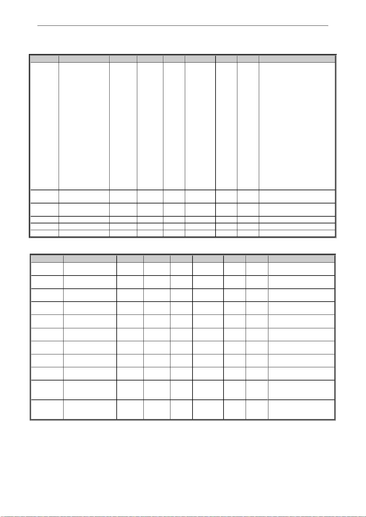
54 • VACON® apfiff20 crane control
Local contacts: http://drives.danfoss.com/danfoss-drives/local-contacts/
Classified as Public
6.2 Reference Handling
6.2.1 Basic Settings
Code
Parameter
Min
Max
Unit
Default
Cust
ID
Note
P2.2.1
I/O Reference
0
19 0 117
0=AI1
1=AI2
2=AI1+AI2
3=AI1-AI2
4=AI2-AI1
5=AI1xAI2
6=AI1 Joystick
7=AI2 Joystick
8=Keypad
9=Fieldbus
10=Motor potentiometer
11=AI1, AI2 minimum
12=AI1, AI2 maximum
13=Max frequency
14=AI1/AI2 selection
15=Encoder 1
16=Encoder 2
17=Preset Speeds
18=Master Reference
19=Master Ramp Out
P2.2.2
Keypad reference
selector
0
19 8 121
See par 2.2.1
P2.2.3
Fieldbus control
reference
0
19 9 122
See par. 2.2.1
P2.2.4
I/O Reference 2
0
19 1 131
See ID117 & ID422
P2.2.5
Speed Share
-300.00
300.00
%
100.00
1241
P2.2.6
Load Share
0.0
500.0
%
100.0
1248
6.2.2 Constant Reference
Code
Parameter
Min
Max
Unit
Default
Cust
ID
Note
P2.2.7.1
Jogging speed
reference
0.00
320.00
Hz
5.00
124 P2.2.7.2
Preset speed 0
0.00
320.00
Hz
0.00
1810
P2.2.7.3
Preset speed 1
0.00
320.00
Hz
10.00
105
Multi-step speed 1
P2.2.7.4
Preset speed 2
0.00
320.00
Hz
15.00
106
Multi-step speed 2
P2.2.7.5
Preset speed 3
0.00
320.00
Hz
20.00
126
Multi-step speed 3
P2.2.7.6
Preset speed 4
0.00
320.00
Hz
25.00
127
Multi-step speed 4
P2.2.7.7
Preset speed 5
0.00
320.00
Hz
30.00
128
Multi-step speed 5
P2.2.7.8
Preset speed 6
0.00
320.00
Hz
40.00
129
Multi-step speed 6
P2.2.7.9
Preset speed 7
0.00
320.00
Hz
50.00
130
Multi-step speed 7
P2.2.7.10
Inching reference 1
-320.00
320.00
Hz
2.00
1239
P2.2.7.11
Inching reference 2
-320.00
320.00
Hz
-2.00
1240
Page 55

apfiff20 crane control 55 • VACON®
Local contacts: http://drives.danfoss.com/danfoss-drives/local-contacts/
Classified as Public
6.2.3 Torque Reference
Code
Parameter
Min
Max
Unit
Default
Cust
ID
Note
P2.2.9.1
Torque reference
selection
0 9
0 641
0=Not used
1=AI1
2=AI2
3=AI3
4=AI4
5=AI1 joystick (-10–10
V)
6=AI2 joystick (-10–10
V)
7=Torque reference from
keypad, R3.5
8=FB Torque Reference
9=Master Torque
P2.2.8.2
Torque reference
max.
–300.0
300.0 % 100
642
P2.2.8.3
Torque reference
min.
–300.0
300.0 % 0.0
643
P2.2.8.4
Torque reference
filtering time
0
32000
ms
0
1244
P2.2.8.5
Torque Reference
Dead Zone
0.0
300.0 % 0.00
1246
P2.2.8.6
Torque Select
0 5
2
1278
0=Speed Control
1=Maximum freq. limit
2=Ramp Output
3=Min
4=Max
5=Window
P2.2.8.7
Window negative
0.00
50.00
Hz
2.00
1305
P2.2.8.8
Window positive
0.00
50.00
Hz
2.00
1304
P2.2.8.9
Window negative off
0.00
P2.10.11
Hz
0.00
1307
P2.2.8.10
Window positive off
0.00
P2.10.12
Hz
0.00
1306
6.2.3.1 Torque Reference OL Settings
Code
Parameter
Min
Max
Unit
Default
Cust
ID
Note
P2.2.8.11.1
Open loop torque
control minimum
frequency
0.00
50.00
Hz
3.00
636
P2.2.8.11.2
Open loop torque
controller
P gain
0
32000 150
639
P2.2.8.11.3
Open loop torque
controller
I gain
0
32000 10
640
Page 56

56 • VACON® apfiff20 crane control
Local contacts: http://drives.danfoss.com/danfoss-drives/local-contacts/
Classified as Public
6.2.4 Prohibit frequency parameters
Code
Parameter
Min
Max
Unit
Default
Cust
ID
Note
P2.2.9.1
Prohibit frequency
range 1 low limit
-1.00
320.00
Hz
0.00
509
0=Not used
P2.2.9.2
Prohibit frequency
range 1 high limit
0.00
320.00
Hz
0.00
510
0=Not used
P2.2.9.3
Ramp time factor
0.1
10.0 x 1.0
518
Multiplier of the currently
Selected ramp time
between prohibit
frequency limits.
Table 6-2. Prohibit frequencies (G2.5)
6.2.5 Motor Potentiometer
Code
Parameter
Min
Max
Unit
Default
Cust
ID
Note
P2.2.10.
1
Motor potentiometer
ramp rate
0.10
2000.00
Hz/s
1.00
331
Ramp rate for motor
potentiometer
P2.2.10.
2
Motor potentiometer
frequency reference
memory reset
0 3 1
367
0=No reset
1=Reset in stop state
2=Reset in powered down
3=StopReq;Fout
P2.2.10.
3
Motor potentiometer
reference copy
0 2 0
366
0=No copy
1=Copy Reference
2=Copy output frequency
Table 6-3. Motor potentiomer (G2.5)
6.2.6 Adjust Reference
Code
Parameter
Min
Max
Unit
Default
Cust
ID
Note
P2.2.11.1
Adjust input
0 5 0
493
0=Not used
1=AI1
2=AI2
3=AI3
4=AI4
5=Fieldbus
P2.2.11.2
Adjust minimum
0.0
100.0 % 0.0
494
Adjust limit to decrease
ref.
P2.2.11.3
Adjust maximum
0.0
100.0 % 0.0
495
Adjust limit to increase
ref.
Page 57

apfiff20 crane control 57 • VACON®
Local contacts: http://drives.danfoss.com/danfoss-drives/local-contacts/
Classified as Public
6.2.7 End limits reference handling
Code
Parameter
Min
Max
Unit
Default
Cust
ID
Note
P2.2.12.1
Disable Negative
Direction
0.1
E.10
DigIn
0.2
1814
P2.2.12.2
Disable Positive
Direction
0.1
E.10
DigIn
0.2
1813
P2.2.12.3
Limit Negative
Reference DI
0.1
E.10
DigIn
0.2
1827
P2.2.12.4
Limit Positive
Reference DI
0.1
E.10
DigIn
0.2
1828
P2.2.12.5
Limited Negative
Reference Hz
-320.00
0.00
Hz
-10.00
1829
P2.2.12.6
Limited Positive
Reference Hz
0.00
320.00
Hz
10.00
1830
P2.2.12.7
Limit Negative
Reference DI 2
0.1
E.10
DigIn
0.2
1831
P2.2.12.8
Limit Positive
Reference DI 2
0.1
E.10
DigIn
0.2
1842
P2.2.12.9
Limited Negative
Reference Hz 2
-320.00
0.00
Hz
-2.00
1845
P2.2.12.1
0
Limited Positive
Reference Hz 2
0.00
320.00
Hz
2.00
1848
P2.2.12.1
1
End Limit Ramp
Time
0.1
320.0 s 1.0
1815
P2.2.12.1
2
Anti-Swing at End
Limits
0 3 0
1856
0=Anti-Swing Active
1=Off at Disabled
2=Off at Disabled and 2nd
limit
3=Off at all limits
Page 58

58 • VACON® apfiff20 crane control
Local contacts: http://drives.danfoss.com/danfoss-drives/local-contacts/
Classified as Public
6.3 Ramp Control
6.3.1 Basic Settings
Code
Parameter
Min
Max
Unit
Default
Cust
ID
Note
P2.3.1
Start function
0 1
0 505
0=Ramp
1=Flying start
P2.3.2
Stop function
0 1
1 506
0=Coasting
1=Ramp
P2.3.3
Acceleration time 1
0.2
3270.0 s 3.0
103
0 Hz to Max frequency
P2.3.4
Deceleration time 1
0.2
3270.0 s 3.0
104
Max frequency to 0 Hz
P2.3.5
Ramp 1 shape
0
100 % 2 500
0=Linear
>0=S-curve ramp time
P2.3.6
Acceleration time 2
0.2
3270.0
s
10.0
502
P2.3.7
Deceleration time 2
0.2
3270.0
s
10.0
503
P2.3.8
Ramp 2 shape
0
100 % 4 501
0=Linear
>0=S-curve ramp time
P2.3.9
Inching Ramp
0.01
320.00
s
1.00
1257
P2.3.10
Reducing of
acc./dec. times
0 5
0 401
Scales active ramp from
100 % to 10 %.
0=Not used
1=AI1
2=AI2
3=AI3
4=AI4
5=Fieldbus
P2.3.11
Disabled direction
ramp
0
3270.0 s 1.0
1815
6.3.2 Quick Stop
Code
Parameter
Min
Max
Unit
Default
Cust
ID
Note
P2.3.12.1
Quick Stop Mode
0 1
1
1276
0=Coasting
1= Ramp
P2.3.13.2
Quick Stop Ramp
time
0.1
3200.0
s
10.0
1256
6.3.3 Ramp Control Options
Code
Parameter
Min
Max
Unit
Default
Cust
ID
Note
P2.3.13.1
Ramp: Skip S2
0 1 1
1900
P2.3.13.2
CL Ramp
Follower Encoder
Frequency
0 1
0
1902
P2.3.13.3
Ramp Input
Interpolator TC
0
200
ms
1
1184
Page 59

apfiff20 crane control 59 • VACON®
Local contacts: http://drives.danfoss.com/danfoss-drives/local-contacts/
Classified as Public
6.3.4 Slack Rope and Shock Load functions
Code
Parameter
Min
Max
Unit
Default
Cust
ID
Note
P 2.3.14.1
Slack Rope
Mode
1 0
0 / Not in
use
1930
P 2.3.14.2
ShockLoadMod
e
1 0
0 / Not in
use
1933
P 2.3.14.3
LoadOnHookTor
q
300 0 %
20
1931
P 2.3.14.4
LoadOfHookTor
q
300 0 %
10
1932
P 2.3.14.5
ShockLoadTorq
300
-300 % 30
1934
P 2.3.14.6
ShockLoadTime
10000
0
ms
500
1935
P 2.3.14.7
ShockTorqRiseT
im
10000
0
ms
50
1936
P 2.3.14.8
ShockLoadRef
50 0 Hz 1
1937
Page 60

60 • VACON® apfiff20 crane control
Local contacts: http://drives.danfoss.com/danfoss-drives/local-contacts/
Classified as Public
6.4 Input Signals
6.4.1 Basic Settings
Code
Parameter
Min
Max
Unit
Default
Cust
ID
Note
P2.4.1.1
Start/Stop logic
selection
0 8 5
300
Start
signal 1
(Default:
DIN1)
Start
signal 2
(Default:
DIN2)
0
1
2
3
4
5
6
7
8
Start fwd
Start/Stop
Start/Stop
Start pulse
Start
Start fwd*
Start*/Stop
Start*/Stop
Start pulse
Start rvs
Reverse
Run enable
Stop pulse
Mot.Pot UP
Start rvs*
Reverse
Run Enable
Stop pulse
Table 6-4. Input signals: basic settings, G2.2.1
* = Rising edge required to start
Page 61

apfiff20 crane control 61 • VACON®
Local contacts: http://drives.danfoss.com/danfoss-drives/local-contacts/
Classified as Public
6.4.2 Digital inputs
Code
Parameter
Default
Cust
ID
Note
P2.4.2.1
Start signal 1
0.1
403
Forward, See ID300
P2.4.2.2
Start signal 2
0.1
404
Reverse. See ID300
P2.4.2.3
Run enable
0.2
407
Motor start enabled (cc)
P2.4.2.4
Reverse
0.1
412
Direction forward (oc)
Direction reverse (cc)
P2.4.2.5
Preset speed 1
0.1
419
See preset speeds in basing
parameter group G2.1
P2.4.2.6
Preset speed 2
0.1
420
P2.4.2.7
Preset speed 3
0.1
421
P2.4.2.8
Motor potentiometer reference
DOWN
0.1
417
Mot.pot. reference decreases (cc)
P2.4.2.9
Motor potentiometer reference UP
0.1
418
Mot.pot. reference increases (cc)
P2.4.2.10
Fault reset
0.1
414
All faults reset (cc)
P2.4.2.11
External fault (close)
0.1
405
Ext. fault displayed (cc)
P2.4.2.12
External fault (open)
0.2
406
Ext. fault displayed (oc)
P2.4.2.13
Acc/Dec time selection
0.1
408
Acc/Dec time 1 (oc)
Acc/Dec time 2 (cc)
P2.4.2.14
Acc/Dec prohibit
0.1
415
Acc/Dec prohibited (cc)
P2.4.2.15
DC braking
0.1
416
DC braking active (cc)
P2.4.2.16
Jogging speed
0.1
413
Jogging speed selected for frequency
reference (cc)
P2.4.2.17
IO reference 1 / 2 selection
0.1
422
IO reference selection:14 ID117
P2.4.2.18
Control from I/O terminal
0.1
409
Force control place to I/O terminal (cc)
P2.4.2.19
Control from keypad
0.1
410
Force control place to keypad (cc)
P2.4.2.20
Control from fieldbus
0.1
411
Force control place to fieldbus (cc)
P2.4.2.21
Parameter set 1/set 2 selection
0.1
496
Closed cont.=Set 2 is used
Open cont.=Set 1 is used
P2.4.2.22
Motor control mode 1/2
0.1
164
Closed cont.=Mode 2 is used
Open cont.=Mode 1 is used
See par 2.6.1, 2.6.12
P2.4.2.23
External Brake Acknowledge
0.2
1210
Monitoring signal from mechanical
brake. Logic activate when 0.3 or
greater
P2.4.2.24
Cooling Monitor
0.2
750
Used when water cooled unit
P2.4.2.25
Enable Inching
0.1
532
Enables Inching function
P2.4.2.26
Inching 1
0.1
531
Inching reference 1 (Default Forward 2
Hz. See P2.4.16). This will start the
drive.
P2.4.2.27
Inching 2
0.1
532
Inching reference 2 (Default Reverse 2 Hz. See P2.4.17). This will start the
drive.
P2.4.2.28
2nd frequency Limit
0.1
1511
Activates second freq. Limit
P2.2.7.31 2nd Freq Limit
P2.4.2.29
Reset Position
0.1
1090
P2.4.2.30
MF Mode 2
0.1
1092
P2.4.2.31
Quick Stop
0.2
1213
P2.4.2.32
Motoring Torque Limit 1
0.1
1624
P2.4.2.33
Generator Torque Limit 1
0.1
1626
P2.4.2.34
PID Activation
0.1
1804
P2.4.2.35
Store Parameter Set
0.1
1753
Stores active parameter set to
selected parameter set
P2.4.2.36
Start Place A/B
0.1
425
Changes start signals between A and
B places.
P2.4.2.37
Start signal 1B
0.1
403
Forward, See ID300
P2.4.2.38
Start signal 2B
0.1
404
Reverse. See ID300
P2.4.2.39
Disable Negative Direction
0.2
1814
P2.4.2.40
Disable Positive Direction
0.2
1813
P2.4.2.41
SB Control
0.1
1952
P2.4.2.42
Set Rope Length
0.1
1916
P2.4.2.43
Set Rope Zero Length
0.1
1917
Table 6-5. Digital input signals, G2.2.4
Page 62

62 • VACON® apfiff20 crane control
Local contacts: http://drives.danfoss.com/danfoss-drives/local-contacts/
Classified as Public
6.4.3 Analogue input 1
Code
Parameter
Min
Max
Unit
Default
Cust
ID
Note
P2.4.3.1
AI1 signal selection
0.1
E.10 A.1
377
Slot . Board input No.
P2.4.3.2
AI1 filter time
0.000
32.000
s
0.000
324
0=No filtering
P2.4.3.3
AI1 signal range
0 3
0
320
0=0…100%*
1=20…100%* 4 mA Fault
2= -10V…+10V*
3= Custom range*
P2.4.3.4
AI1 custom minimum
setting
-160.00
160.00
%
0.00
321
Custom Range:
Minimum input
P2.4.3.5
AI1 custom
maximum setting
-160.00
160.00
%
100.00
322
Custom Range:
Maximum input
P2.4.3.6
AI1 reference
scaling, minimum
value
0.00
320.00
Hz
0.00
303
Selects the frequency that
corresponds to the min.
reference signal
P2.4.3.7
AI1 reference
scaling, maximum
value
0.00
320.00
Hz
0.00
304
Selects the frequency that
corresponds to the max.
reference signal
P2.4.3.8
AI1 joystick Dead
Zone
0.00
20.00
%
2.00
384
Dead Zone for joystick
input
P2.4.3.9
AI1 sleep limit
0.00
100.00
%
0.00
385
Drive goes to stop if input
is below this limit for this
time.
P2.4.3.10
AI1 sleep delay
0.00
320.00
s
0.00
386
P2.4.3.11
AI1 joystick offset
-100.00
100.00
%
0.00
165
Press enter for 1s to set
offset
Table 6-6. Analogue input 1 parameters, G2.2.2
6.4.4 Analogue input 2
Code
Parameter
Min
Max
Unit
Default
Cust
ID
Note
P2.4.4.1
AI2 signal selection
0.1
E.10 A.2
388
Slot . Board input No.
P2.4.4.2
AI2 filter time
0.000
32.000
s
0.000
329
0=No filtering
P2.4.4.3
AI2 signal range
0 3
1
325
0=0…100%*
1=20…100%* 4 mA Fault
2= -10V…+10V*
3=Custom range*
P2.4.4.4
AI2 custom minimum
setting
-160.00
160.00
%
0.00
326
Custom Range:
Minimum input
P2.4.4.5
AI2 custom
maximum setting
-160.00
160.00
%
100.00
327
Custom Range:
Maximum input
P2.4.4.6
AI2 reference
scaling, minimum
value
0.00
320.00
Hz
0.00
393
Selects the frequency that
corresponds to the min.
reference signal
P2.4.4.7
AI2 reference
scaling, maximum
value
0.00
320.00
Hz
0.00
394
Selects the frequency that
corresponds to the max.
reference signal
P2.4.4.8
AI2 joystick Dead
Zone
0.00
20.00
%
2.00
395
Dead Zone for joystick
input
P2.4.4.9
AI2 sleep limit
0.00
100.00
%
0.00
396
Drive goes to stop if input
is below this limit for this
time.
P2.4.4.10
AI2 sleep delay
0.00
320.00
s
0.00
397
P2.4.4.11
AI2 joystick offset
-100.00
100.00
%
0.00
166
Press enter for 1s to set
offset
Table 6-7. Analogue input 2 parameters, G2.2.3
*Remember to place jumpers of block X2 accordingly.
See NX User Manual, chapter 6.2.2.2
Page 63
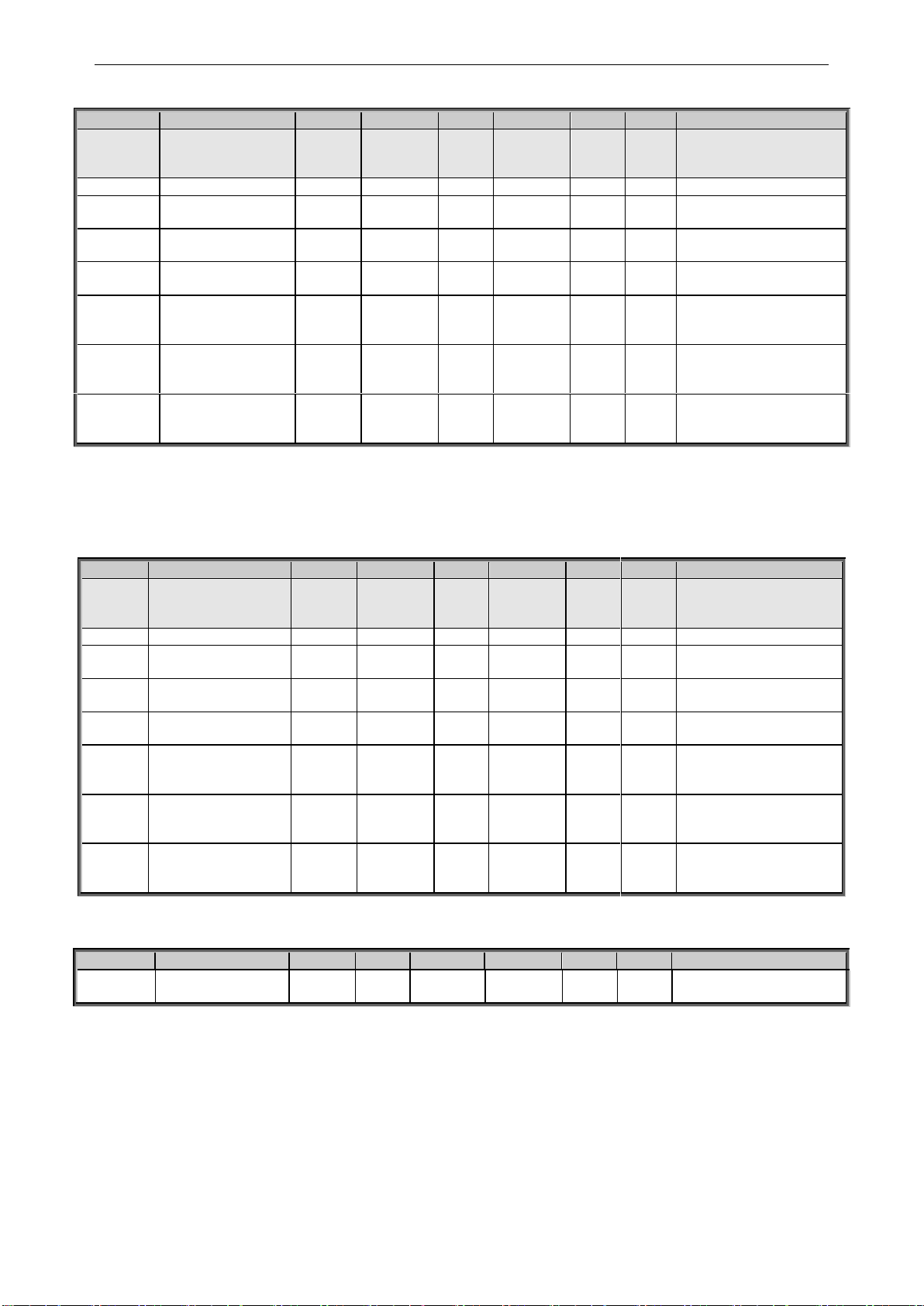
apfiff20 crane control 63 • VACON®
Local contacts: http://drives.danfoss.com/danfoss-drives/local-contacts/
Classified as Public
6.4.5 Analogue input 3
Code
Parameter
Min
Max
Unit
Default
Cust
ID
Note
P2.4.5.1
AI3 signal selection
0.1
E.10 0.1
141
Slot . Board input No.
If 0.1 ID27 can be
controlled from FB
P2.4.5.2
AI3 filter time
0.000
32.000
s
0.000
142
0=No filtering
P2.4.5.3
AI3 custom minimum
setting
-160.00
160.00
%
0.00
144
Custom range always
active. See ID326
P2.4.5.4
AI3 custom
maximum setting
-160.00
160.00
%
100.00
145
Custom range always
active. See ID327
P2.4.5.5
AI3 signal inversion
0 1
0
151
0=Not inverted
1=Inverted
P2.4.5.6
AI3 reference
scaling, minimum
value
-32000
32000 0
1037
Selects the value that
corresponds to the min.
reference signal
P2.4.5.7
AI3 reference
scaling, maximum
value
-32000
32000 0
1038
Selects the value that
corresponds to the max.
reference signal
P2.4.5.8
AI3 Controlled ID
0
10000 0
1509
Select parameter that
you want to control by ID
number.
Table 6-8. Analogue input 3 parameters, G2.2.4
6.4.6 Analogue input 4
Code
Parameter
Min
Max
Unit
Default
Cust
ID
Note
P2.4.6.1
AI4 signal selection
0.1
E.10 0.1
152
Slot . Board input No.
If 0.1 ID28 can be
controlled from FB
P2.4.6.2
AI4 filter time
0.000
32.000
s
0.000
153
0=No filtering
P2.4.6.3
AI4 custom minimum
setting
-160.00
160.00
%
0.00
155
Custom range always
active. See ID326
P2.4.6.4
AI4 custom maximum
setting
-160.00
160.00
%
100.00
156
Custom range always
active. See ID327
P2.4.6.5
AI4 signal inversion
0 1
0 162
0=Not inverted
1=Inverted
P2.4.6.6
AI3 reference scaling,
minimum value
-32000
-32000 0
1039
Selects the value that
corresponds to the min.
reference signal
P2.4.6.7
AI3 reference scaling,
maximum value
-32000
32000 0
1040
Selects the value that
corresponds to the max.
reference signal
P2.4.6.8
AI4 Controlled ID
0
10000 0
1510
Select parameter that
you want to control by
ID number.
Table 6-9. Analogue input 4 parameters, G2.2.5
6.4.7 Options
Code
Parameter
Min
Max
Unit
Default
Cust
ID
Note
P2.4.7.1
Input signal inversion
Control
0
6553
5
2
1091
**Remember to place jumpers of block X2 accordingly.
See NX User Manual, chapter 6.2.2.2
Page 64

64 • VACON® apfiff20 crane control
Local contacts: http://drives.danfoss.com/danfoss-drives/local-contacts/
Classified as Public
6.5 Output Signals
6.5.1 Digital output signals
Code
Parameter
Min
Default
Cust
ID
Note
P2.5.1.1
Ready
0.1
0.1
432
Ready to Run
P2.5.1.2
Run
0.1
0.1
433
Running
P2.5.1.3
Fault
0.1
0.1
434
Drive in fault state
P2.5.1.4
Inverted fault
0.1
0.1
435
Drive not in fault state
P2.5.1.5
Warning
0.1
0.1
436
Warning active
P2.5.1.6
External fault
0.1
0.1
437
External fault active
P2.5.1.7
Reference fault/warning
0.1
0.1
438
4 mA fault active
P2.5.1.8
Over temperature warning
0.1
0.1
439
Drive over temperature
active
P2.5.1.9
Reverse
0.1
0.1
440
Output frequency < 0 Hz
P2.5.1.10
Unrequested direction
0.1
0.1
441
Reference <> Output
frequency
P2.5.1.11
At speed
0.1
0.1
442
Reference = Output
frequency
P2.5.1.12
Jogging speed
0.1
0.1
443
Jogging or preset speed
command active
P2.5.1.13
External control place
0.1
0.1
444
IO control active
P2.5.1.14
External brake control, Direct
0.1
0.1
446
See explanations on
chapter Brake Control
P2.5.1.15
External brake control, Invert
0.1
0.1
445
P2.5.1.16
Output frequency limit 1
supervision
0.1
0.1
447
See ID315
P2.5.1.17
Output frequency limit 2
supervision
0.1
0.1
448
See ID346
P2.5.1.18
Reference limit supervision
0.1
0.1
449
See ID350
P2.5.1.19
Temperature limit supervision
0.1
0.1
450
Drive temperature
supervision. See ID354
P2.5.1.20
Torque limit supervision
0.1
0.1
451
See ID348
P2.5.1.21
Motor thermal protection
0.1
0.1
452
Thermistor fault or warning
P2.5.1.22
Analogue input supervision limit
0.1
0.1
463
See ID356
P2.5.1.23
Motor regulator activation
0.1
0.1
454
One of limit controller is
active
P2.5.1.24
Fieldbus digital input 1
0.1
0.1
455
FB CW B11
P2.5.1.25
FB Dig 1 Parameter
ID0
ID0
891
Select parameter to control
P2.5.1.26
Fieldbus digital input 2
0.1
0.1
456
FB CW B12
P2.5.1.27
FB Dig 2 Parameter
ID0
ID0
892
Select parameter to control
P2.5.1.28
Fieldbus digital input 3
0.1
0.1
457
FB CW B13
P2.5.1.29
FB Dig 3 Parameter
ID0
ID0
893
Select parameter to control
P2.5.1.30
Fieldbus digital input 4
0.1
0.1
169
FB CW B14
P2.5.1.31
FB Dig 4 Parameter
ID0
ID0
894
Select parameter to control
P2.5.1.32
Fieldbus digital input 5
0.1
0.1
170
FB CW B15
P2.5.1.33
FB Dig 5 Parameter
ID0
ID0
895
Select parameter to control
P2.5.1.34
Safe Disable Active
0.1
0.1
756
P2.5.1.35
Brake Slipping
0.1
0.1
1786
Page 65

apfiff20 crane control 65 • VACON®
Local contacts: http://drives.danfoss.com/danfoss-drives/local-contacts/
Classified as Public
6.5.2 Analogue output 1
Code
Parameter
Min
Max
Unit
Default
Cust
ID
Note
P2.5.2.1
Analogue output 1
signal selection
0.1
E.10 A.1
464
TTF programming
See chapter 3.1 and 3.2
P2.5.2.2
Analogue output 1
function
0
20 0
307
0=Not used (4 mA / 2 V)
1=Output freq. (0—f
max
)
2=Freq. reference (0—
f
max
)
3=Motor speed (0—Motor
nominal speed)
4=Motor current (0—
I
nMotor
)
5=Motor torque (0—
T
nMotor
)
6=Motor power (0—
P
nMotor
)
7=Motor voltage (0-U
nMotor
)
8=DC-link volt (0—1000V)
9=AI1
10=AI2
11=Output freq. (f
min
- f
max
)
12=-
2xTorque…+2xTorqu
e
13=-2xPower…+2xPower
14=PT100 temperature
15=FB Analog Output
16= -2xSpeed…+2xSpeed
17= Encoder speed (0—
Motor nominal speed)
18=Final Freq.Ref
19= Value Control Out
20=Drive Output Power
P2.5.2.3
Analogue output 1
filter time
0.00
10.00
s
1.00
308
0=No filtering
P2.5.2.4
Analogue output 1
inversion
0 1 0
309
0=Not inverted
1=Inverted
P2.5.2.5
Analogue output 1
minimum
0 1 0
310
0=0 mA (0 %)
1=4 mA (20 %)
P2.5.2.6
Analogue output 1
scale
10
1000 % 100
311
P2.5.2.7
Analogue output 1
offset
-100.00
100.00
%
0.00
375
Table 6-10. Analogue output 1 parameters, G2.3.5
6.5.3 Analogue output 2
Code
Parameter
Min
Max
Unit
Default
Cust
ID
Note
P2.5.3.1
Analogue output 2
signal selection
0.1
E.10 0.1
471
TTF programming
See chapter 3.1 and 3.2
P2.5.3.2
Analogue output 2
function
0
20 4
472
See P2.5.2.2
P2.5.3.3
Analogue output 2
filter time
0.00
10.00
s
1.00
473
0=No filtering
P2.5.3.4
Analogue output 2
inversion
0 1 0
474
0=Not inverted
1=Inverted
P2.5.3.5
Analogue output 2
minimum
0 1 0
475
0=0 mA (0 %)
1=4 mA (20 %)
P2.5.3.6
Analogue output 2
scale
10
1000 % 100
476 P2.5.3.7
Analogue output 2
offset
-100.00
100.00
%
0.00
477
Table 6-11. Analogue output 2 parameters, G2.3.6
Page 66

66 • VACON® apfiff20 crane control
Local contacts: http://drives.danfoss.com/danfoss-drives/local-contacts/
Classified as Public
6.5.4 Analogue output 3
Code
Parameter
Min
Max
Unit
Default
Cust
ID
Note
P2.5.4.1
Analogue output 3
signal selection
0.1
E.10 0.1
478
TTF programming
See chapter 3.1 and 3.2
P2.5.4.2
Analogue output 3
function
0
20 5
479
See P2.5.2.2
P2.5.4.3
Analogue output 3
filter time
0.00
10.00
s
1.00
480
0=No filtering
P2.5.4.4
Analogue output 3
inversion
0 1 0
481
0=Not inverted
1=Inverted
P2.5.4.5
Analogue output 3
minimum
0 1 0
482
0=0 mA (0 %)
1=4 mA (20 %)
P2.5.4.6
Analogue output 3
scale
10
1000 % 100
483
P2.5.4.7
Analogue output 3
offset
-100.00
100.00
%
0.00
484
Table 6-12. Analogue output 3 parameters, G2.3.7
6.5.5 Analogue output 4
Code
Parameter
Min
Max
Unit
Default
Cust
ID
Note
P2.5.5.1
Analogue output 4
signal selection
0.1
E.10 0.1
1527
TTF programming
See chapter 3.1 and 3.2
P2.5.5.2
Analogue output 4
function
0
20 5
1520
See P2.5.2.2
P2.5.5.3
Analogue output 4
filter time
0.00
10.00
s
1.00
1521
0=No filtering
P2.5.5.4
Analogue output 4
inversion
0 1 0
1522
0=Not inverted
1=Inverted
P2.5.5.5
Analogue output 4
minimum
0 1 0
1523
0=0 mA (0 %)
1=4 mA (20 %)
P2.5.5.6
Analogue output 4
scale
10
1000 % 100
1525
P2.5.5.7
Analogue output 4
offset
-100.00
100.00
%
0.00
1524
Table 6-13. Analogue output 4 parameters, G2.3.8
Page 67

apfiff20 crane control 67 • VACON®
Local contacts: http://drives.danfoss.com/danfoss-drives/local-contacts/
Classified as Public
6.5.6 Delayed digital output 1
Code
Parameter
Min
Max
Unit
Default
Cust
ID
Note
P2.5.6.1
Digital output 1
signal selection
0.1
E.10 0.1
486
Possibility to invert by
ID1091 INV Commands
P2.5.6.2
Digital output 1
function
0
28 1
312
0=Not used
1=Ready
2=Run
3=Fault
4=Fault inverted
5=FC overheat warning
6=Ext. fault or warning
7=Ref. fault or warning
8=Warning
9=Reverse
10=Jogging spd selected
11=At speed
12=Mot. regulator active
13=Freq. limit 1 superv.
14=Freq. limit 2 superv.
15=Torque limit superv.
16=Ref. limit supervision
17= Brake Open, Invert.
18=I/O control place act.
19=FC temp. limit superv.
20=Reference inverted
21=Brake Open, Direct.
22=Therm. fault or warn.
23=On/Off control
24=Fieldbus input data 1
25=Fieldbus input data 2
26=Fieldbus input data 3
27=Warning Set Reset
28=ID.Bit Select
P2.5.6.3
Digital output 1 on
delay
0.00
320.00
s
0.00
487
0.00 = On delay not in
use
P2.5.6.4
Digital output 1 off
delay
0.00
320.00
s
0.00
488
0.00 = Off delay not in
use
P2.5.6.5
Invert delayed DO1
0 1 0
1587
0=Not inverted
1=Inverted
P2.5.6.6
ID.Bit Free DO
0.00
2000.15
0.00
1217
P2.5.6.7
DO1 Time Scale
0 2 0
1060
0 = s
1 = min
2 = h
Table 6-14. Delayed digital output 1 parameters, G2.3.1
6.5.7 Delayed digital output 2
Code
Parameter
Min
Max
Unit
Default
Cust
ID
Note
P2.5.7.1
Digital output 2
signal selection
0.1
E.10 0.1
489
Possibility to invert by
ID1091 INV Commands
P2.5.7.2
Digital output 2
function
0
28 0
490
See P2.5.6.2
P2.5.7.3
Digital output 2 on
delay
0.00
320.00
s
0.00
491
0.00 = On delay not in
use
P2.5.7.4
Digital output 2 off
delay
0.00
320.00
s
0.00
492
0.00 = Off delay not in
use
P2.5.7.5
Invert delayed DO2
0 1 0
1588
0=Not inverted
1=Inverted
P2.5.7.6
ID.Bit Free DO
0.00
2000.15
0.00
1385
P2.5.7.7
DO2 Time Scale
0 2 0
1061
0 = s
1 = min
2 = h
Table 6-15. Delayed digital output 2 parameters, G2.3.2
Page 68

68 • VACON® apfiff20 crane control
Local contacts: http://drives.danfoss.com/danfoss-drives/local-contacts/
Classified as Public
6.5.8 Supervision Limits
Code
Parameter
Min
Max
Unit
Default
Cust
ID
Note
P2.5.8.1
Output frequency
limit 1 supervision
0 2 0
315
0=No limit
1=Low limit supervision
2=High limit supervision
P2.5.8.2
Output frequency
limit 1;
Supervised value
0.00
320.00
Hz
0.00
316 P2.5.8.3
Output frequency
limit 2 supervision
0 2 0
346
0=No limit
1=Low limit supervision
2=High limit supervision
P2.5.8.4
Output frequency
limit 2;
Supervised value
0.00
320.00
Hz
0.00
347
P2.5.8.5
Torque limit
supervision
0 2 0
348
0=Not used
1=Low limit supervision
2=High limit supervision
P2.5.8.6
Torque limit
supervision value
-300.0
300.0
%
100.0
349 P2.5.8.7
Reducing of torque
supervision limit
0 5
0
402
P2.5.8.8
Reference limit
supervision
0 2 0
350
0=Not used
1=Low limit
2=High limit
P2.5.8.9
Reference limit
supervision value
0.00
100.0
%
0.00
351
P2.5.8.10
FC temperature
supervision
0 2 0
354
0=Not used
1=Low limit
2=High limit
P2.5.8.11
FC temperature
supervised value
–10
100
C
40
355
P2.5.8.12
Analogue
supervision signal
0
4 0
356
0=Not used
1=AI1
2=AI2
3=AI3
4=AI4
P2.5.8.13
Analogue
supervision low limit
0.00
100.00
%
10.00
357
Reset limit
P2.5.8.14
Analogue
supervision high
limit
0.00
100.00
%
90.00
358
Set limit
Table 6-16. Supervision Limit settings, G2.3.4
Page 69
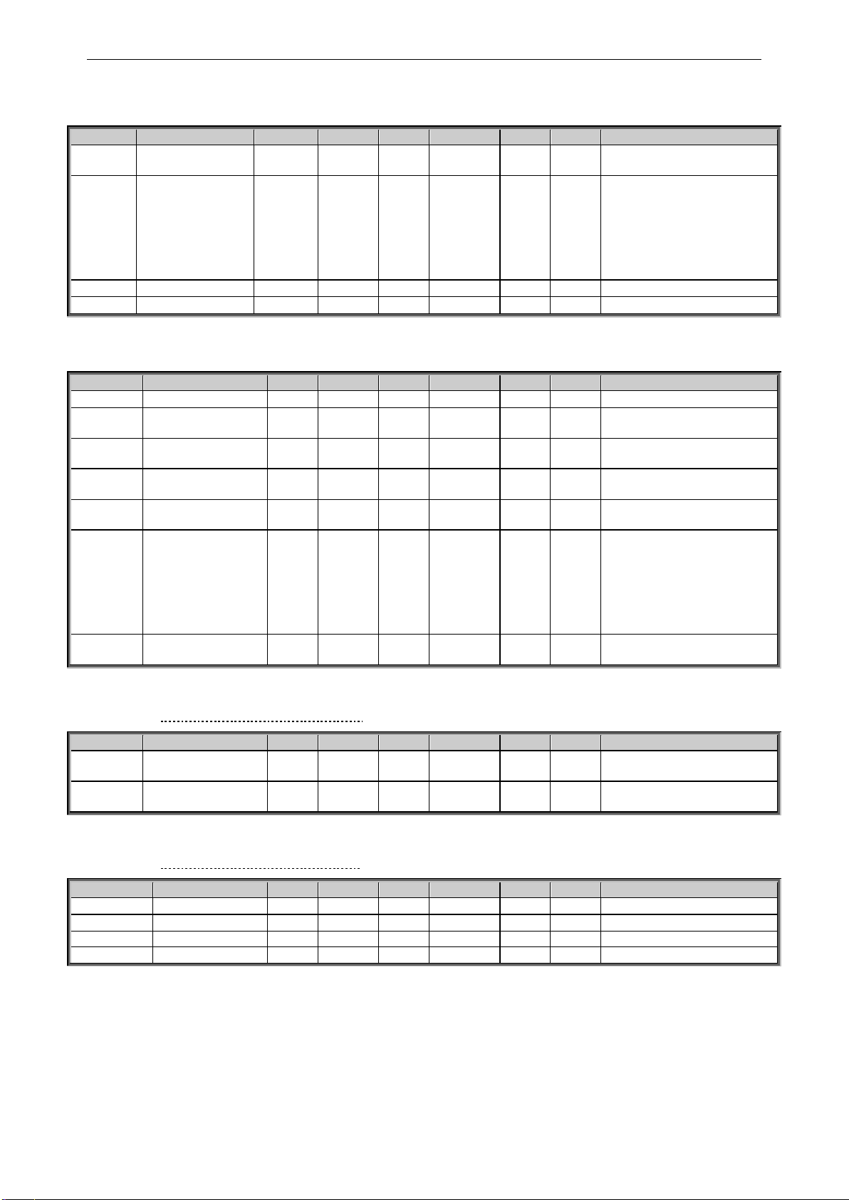
apfiff20 crane control 69 • VACON®
Local contacts: http://drives.danfoss.com/danfoss-drives/local-contacts/
Classified as Public
6.6 Limit Settings
6.6.1 Current handling
Code
Parameter
Min
Max
Unit
Default
Cust
ID
Note
P2.6.1
Current limit
0
2 x IH
A
Unit Max
107
Reaching the limit will lower
the output frequency
P2.6.2
Scaling of current
limit
0 5
0 399
Scaling from 0 to ID107
0=Not used
1=AI1
2=AI2
3=AI3
4=AI4
5=FB Limit Scaling ID46
P2.6.3
Current Limit Kp
1
32000
Varies
1451
P2.6.4
Current Limit Ki
1
32000
Varies
1452
6.6.2 Torque Handling
Code
Parameter
Min
Max
Unit
Default
Cust
ID
Note
P2.6.2.1
Torque Limit
0.0
300.0
%
300.0
609
General maximum limit
P2.6.2.2
Motoring Torque
Limit
0.0
300.0
%
300.0
1287
Motoring side torque limit
P2.6.2.3
Generator Torque
Limit
0.0
300.0
%
300.0
1288
Generator side torque limit
P2.6.2.4
Motoring Torque
Limit 1
0.0
300.0
%
300.0
1625
P2.6.2.5
Generator Torque
limit 1
0.0
300.0
%
300.0
1627
P2.6.2.6
Scaling Motoring
Torque limit
0 5
0 485
Scaling from 0 to ID1287
0=Not used
1=AI1
2=AI2
3=AI3
4=AI4
5=FB Limit Scaling ID46
P2.6.2.7
Scaling Generator
Torque limit
0 5
0
1087
Scaling from 0 to ID1288
As parameter P2.6.3.9
6.6.2.1 Torque Handling OL Settings
Code
Parameter
Min
Max
Unit
Default
Cust
ID
Note
P2.6.2.8.
1
Torque limit control
P-gain
0.0
32000
3000
610
P2.6.2.8.
2
Torque limit control
I-gain
0.0
32000 200
611
6.6.2.2 Torque Handling CL Settings
Code
Parameter
Min
Max
Unit
Default
Cust
ID
Note
P2.6.2.9.1
SPC Out Limit
0.0
300.0
%
300.0
1382
P2.6.2.9.2
SPC Pos Limit
0.0
300.0
%
300.0
646
P2.6.2.9.3
SPC Neg Limit
0.0
300.0
%
300.0
645
P2.6.2.9.4
Pull Out Torque
0.0
600.0
%
500.0
1291
Page 70

70 • VACON® apfiff20 crane control
Local contacts: http://drives.danfoss.com/danfoss-drives/local-contacts/
Classified as Public
6.6.2.3 Run a way load catch for CL
Code
Parameter
Min
Max
Unit
Default
Cust
ID
Note
P2.6.2.10.1
Generator Torque
limit increase speed
level
0.00
320.0
0
Hz
0.00
1547
Function disabled when
zero. Point where Generator
torque limit stars to
increase.
P2.6.2.10.2
Generator Torque
limit increase
maximum speed
limit
0.00
320.0
0
Hz
100.00
1548
Point where torque value of
ID1549 is added to base
generator torque limit.
P2.6.2.10.3
Generator Torque
limit increase
maximum addition
0.0
300.0 % 300.0
1549
6.6.3 Frequency Handling
Code
Parameter
Min
Max
Unit
Default
Cust
ID
Note
P2.6.3.1
Max Frequency 2
0.00
320.00
Hz
35.00
1512
Maximum frequency limit
that is activated by digital
input.
P2.6.3.2
Negative frequency
limit
-320.00
320.00
Hz
-320.00
1286
Alternative limit for negative
direction
P2.6.3.3
Positive frequency
limit
-320.00
320.00
Hz
320.00
1285
Alternative limit for positive
direction
P2.6.3.4
Zero Frequency limit
0.00
320.00
Hz
1.00
1283
P2.6.3.5
Minimum Frequency
Open Loop
0.00
50.00
Hz
Varies
101
Calculated during Brake ID
Run
P2.6.3.6
Minimum Frequency
Closed Loop
0.00
50.00
Hz
0.00
215
Calculated during Brake ID
Run
P2.6.3.7
Acceleration Power
Limit Forward
0.00
600.0
%
300.0
1903
P2.6.3.8
Acceleration Power
Limit Reverse
0.00
600.0
%
300.0
1904
Page 71

apfiff20 crane control 71 • VACON®
Local contacts: http://drives.danfoss.com/danfoss-drives/local-contacts/
Classified as Public
6.6.4 DC-Link Handling
Code
Parameter
Min
Max
Unit
Default
Cust
ID
Note
P2.6.4.1
Overvoltage controller
0 2
0 607
0=Not used
1=Used (no ramping)
2=Used (ramping)
P2.6.4.2
Over Voltage
Reference selector
0 2
1
1262
0=High Voltage
1=Normal Voltage
2=BrakeChopperLevel
P2.6.4.3
Brake chopper
0 4
0 504
0=Disabled
1=Used when running
2=External brake chopper
3=Used when
stopped/running
4=Used when running (no
testing)
P2.6.4.4
Brake Chopper Level
5: 605
6: 836
5: 797
6: 1099
V
1267
P2.6.4.5
Undervoltage
controller
0 2
0 608
0=Not used
1=Used (no ramping)
2=Used (ramping to zero)
P2.6.4.6
Under Voltage Ref
Selector
0 1
1
1537
0=Under Voltage Ref
1= 0.8 * Estimated DC Volt.
P2.6.4.6
Under Voltage
Reference
5:
410
6:
567
5: 540
6: 745
V
Varies
1538
6.6.4.1 DC-Link Handling CL Settings
Code
Parameter
Min
Max
Unit
Default
Cust
ID
Note
P2.6.4.8.
1
Over voltage
reference
94.00
130.0
0
%
118.00
1528
P2.6.4.8.
2
Over voltage
motoring side torque
limit
0.0
300.0 % 10.0
1623
Maximum motoring torque
when over voltage controller
is active.
P2.6.4.8.
3
CL Under Voltage
Reference
60.00
80.00 % 65.00
1567
6.6.5 Limit Settings Options
Code
Parameter
Min
Max
Unit
Default
Cust
ID
Note
P2.6.6.1
Limit Total Current In
Closed Loop
0 1
0
1901
0=No
1=Yes
Page 72

72 • VACON® apfiff20 crane control
Local contacts: http://drives.danfoss.com/danfoss-drives/local-contacts/
Classified as Public
6.7 Flux and DC Current handling
6.7.1 Flux and DC Current handling OL Settings
Code
Parameter
Min
Max
Unit
Default
Cust
ID
Note
P2.7.1.1
DC braking current
0.00
IL A 0.00
507
Calculated during Brake ID
P2.7.1.2
DC braking time
at start
0.00
600.00
s
0.00
516
Calculated during Brake ID
P2.7.1.3
DC braking time
at stop
0.00
600.00
s
0.00
508
Calculated during Brake ID
P2.7.1.4
Frequency to start DC
braking during
ramp stop
0.10
10.00
Hz
1.50
515
P2.7.1.5
DC-Brake Current in
Stop
0.00
IL A Varies
1080
P2.7.1.6
Flux brake
0 1
0 520
0=Off
1=On
P2.7.1.7
Flux braking current
0.00
IL A IH
519
6.7.2 Flux and DC Current handling CL Settings
Code
Parameter
Min
Max
Unit
Default
Cust
ID
Note
P2.7.2.1
Magnetizing current at
start
0
IL A 0.00
627
Calculated during Brake ID
P2.7.2.2
Magnetizing time at
start
0.0
600.0 s 0.0
628
Calculated during Brake ID
P2.7.2.3
Flux Reference
0.0
500.0
%
100.0
1250
P2.7.2.4
Flux Off Delay
-1
32000 s 0
1402
-1=forever
P2.7.2.5
Stop State Flux
0.0
150.0
%
100.0
1401
P2.7.2.6
Reduced Flux Level
0.0
500.0
%
100.0
1613
P2.7.2.7
Reduced Flux
Frequency
0.00
32.00
Hz
0.00
1614
Page 73

apfiff20 crane control 73 • VACON®
Local contacts: http://drives.danfoss.com/danfoss-drives/local-contacts/
Classified as Public
6.8 Motor Control
6.8.1 Motor Control Basic Settings
Code
Parameter
Min
Max
Unit
Default
Cust
ID
Note
P2.8.1
MC mode
0 3
0 694
0= Open Loop
1= Closed Loop
2= Sensorless
3= AOL Control
P2.8.3
Torque Select
0 6
1
1278
0=Frequency Control
1=Speed Control
2=Torque
3=Torque; Ramp Output
4=Torque; Min
5=Torque; Max
6=Torque; Window
6.8.2 Open Loop Settings
Code
Parameter
Min
Max
Unit
Default
Cust
ID
Note
P2.8.3.1
U/f optimisation
0 1
0 109
0=Not used
1=Automatic torque boost
P2.8.3.2
U/f ratio selection
0 3
0 108
0=Linear
1=Squared
2=Programmable
3=Linear with flux optim.
P2.8.3.3
Field weakening point
6.00
320.00
Hz
50.00
602
P2.8.3.4
Voltage at field
weakening point
10.0
0
200.00
%
100.00
603
n% x U
nmot
P2.8.3.5
U/f curve midpoint
frequency
0.00
P2.8.3.3
Hz
50.00
604
P2.8.3.6
U/f curve midpoint
voltage
0.00
100.00
%
100.00
605
n% x U
nmot
Parameter max. value =
P2.6.5
P2.8.3.7
Output voltage at zero
frequency
0.00
40.00
%
0.00
606
n% x U
nmot
P2.8.3.8
Freq. Dir. Change
0
32000
25000
1682
P2.8.3.9
Hoisting ID UF
Strength
33
200 % 90
1905
P2.8.3.10
I/f Start
0 1 0
1809
P2.8.3.11
I/f Current
0.0
150.0
120.0
1693
P2.8.3.12
I/f Control Limit
0.0
300.0
10.0
1790
Calculated during Crane ID
P2.8.3.13
MakeFluxTime
0
32000
ms
200
660
Page 74

74 • VACON® apfiff20 crane control
Local contacts: http://drives.danfoss.com/danfoss-drives/local-contacts/
Classified as Public
6.8.3 Closed Loop Control Settings
Code
Parameter
Min
Max
Unit
Default
Cust
ID
Note
P2.8.4.1
Current control
P gain
0.00
100.00
%
40.00
617 P2.8.4.2
Current control
I Time
0.0
3200.0
ms
1.5
657
P2.8.4.3
Slip adjust
0
500 % 75
619
P2.8.4.4
Acceleration
compensation
0.00
300.00
s
0.00
626
P2.8.4.5
Speed Error Filter TC
0
1000
ms 0
1311
P2.8.4.6
Encoder filter time
0
1000
ms 0
618
P2.8.4.7
Encoder Selection
0 1
0
1595
0=Encoder Input 1
1=Encoder Input 2
P2.8.4.8
Motor Temperature
Compensation mode
0 2
0
1426
0=Not used
1=Internal
2=Measured Temperature
P2.8.4.9
SC Torque Chain
Select
0
65535 0
1557
Default 96 after
identification.
P2.8.4.10
CL MC Mode
0 1
1 691
0=Flux Model 1
1=Flux Model 2
P2.8.4.11
TCDunDampGain
0,00
100,00 % 1576
P2.8.4.12
TCDynDampTC
0
32000
ms 0
1577
Page 75

apfiff20 crane control 75 • VACON®
Local contacts: http://drives.danfoss.com/danfoss-drives/local-contacts/
Classified as Public
6.8.4 PMSM Control settings
Code
Parameter
Min
Max
Unit
Default
Cust
ID
Note
P2.8.5.1
PMSM Shaft
Position
0
65535 0
649
P2.8.5.2
Start Angle
Identification mode
0
10 0
169
1
0=Automatic
1=Forced
2=After Power Up
3=Disabled
P2.8.5.3
Start Angle
Identification DC
Current
0.0
150.0 % 0.0
175
6
P2.8.5.4
Polarity Pulse
Current
-10.0
200.0 % 0.0
156
6
P2.8.5.5
Start Angle ID
Time
0
32000
ms
0
175
5
P2.8.5.6
I/f Current
0.0
150.0
%
50.0
169
3
P2.8.5.7
I/f Control Limit
0.0
300.0
%
10.0
179
0
P2.8.5.8
Flux Current Kp
0
32000
5000
651
P2.8.5.9
Flux Current Ti
0
1000 25
652
P2.8.5.10
External Id
Reference
-150.0
150.0 % 0.0
173
0
P2.8.5.11
Enable Rs
Identification
0 1
1
654
0=No
1=Yes
P2.8.5.12
Lsd Voltage Drop
-32000
32000 0
175
7
P2.8.5.13
Lsq Voltage Drop
-32000
32000 0
175
8
P2.8.5.14
EncIDCurrent
0.0
150.0
%
90.0
173
4
P2.8.5.15
Polarity ID Mode
0 1
173
7
P2.8.5.16
Polarity Pulse
Length
0
1000
ms
200
174
2
P2.8.5.17
Polarity
Detection Angle
0.0
360.0
Deg
1.5
174
8
P2.8.5.18
Angle
Identification
Mode
0 2
174
9
P2.8.5.19
Current Control
Kp d
0
32000 %
176
1
P2.8.5.20
Voltage Margin
0.0
120.0 %
175
9
P2.8.5.21
Encoder ID Run
Mode
0 2 0
680
P2.8.5.22
VoltageCorr. Kp
0,000
32,000
0,100
178
3
P2.8.5.23
VoltageCorr. Ki
0
32000
5000
178
4
Page 76

76 • VACON® apfiff20 crane control
Local contacts: http://drives.danfoss.com/danfoss-drives/local-contacts/
Classified as Public
6.8.5 Stabilators
Code
Parameter
Min
Max
Unit
Default
Cust
ID
Note
P2.8.6.1
Torque Stabilator
Gain
0
1000 100
1412
P2.8.6.2
Torque Stabilator
Damping
0
1000 800
1413
With PMSM use 980
P2.8.6.3
Torque Stabilator
Gain in FWP
0
1000 50
1414
P2.8.6.4
Torque Stabilator
Limit
0
1500 150
1720
P2.8.6.5
Flux Circle Stabilator
Gain
0
32767
10000
1550
P2.8.6.6
Flux Circle Stabilator
TC
0
32700 900
1551
P2.8.6.7
Flux Stabilator Gain
0
32000 500
1797
P2.8.6.8
Flux Stab Coeff
-30000
30000 1796
P2.8.6.9
Voltage Stabilator
Gain
0
100.0 % 10.0
1738
P2.8.6.10
Voltage Stabilator TC
0
1000 900
1552
P2.8.6.11
Voltage Stabilator
Limit
0
320.00
Hz
1.50
1553
6.8.6 Tuning parameters
Code
Parameter
Min
Max
Unit
Default
Cust
ID
Note
P2.8.7.1
Fly Start Options
0
65535 0
1610
P2.8.7.2
MC Options
0
65535 0
1740
P2.8.7.3
Resonance Damping
Select
0
200 0.00
1760
P2.8.7.4
Damping Frequency
0
320.00
Hz 0
1763
P2.8.7.5
Damping Gain
0
32000 0
1764
P2.8.7.6
Damping Phase
0
360 0.00
1765
P2.8.7.7
Damping Activation
Frequency
0
320.00 % 0
1770
P2.8.7.8
Damping Filter Time
Constant
0
32700 105
1771
P2.8.7.9
Over Modulation
Limit
50
120 % 105
1515
If you have sine filter in use
set this to 101 %
P2.8.7.10
Modulator Index Limit
0
200 % 100
655
P2.8.7.11
DC Voltage Filter
0.0
500.0 0.0
1591
P2.8.7.12
GearRatioMultipl
0
32000 1
1558
P2.8.7.13
GearRatioDivider
0
32000 1
1559
Page 77

apfiff20 crane control 77 • VACON®
Local contacts: http://drives.danfoss.com/danfoss-drives/local-contacts/
Classified as Public
6.8.7 Identification parameters
Code
Parameter
Min
Max
Unit
Default
Cust
ID
Note
P2.8.8.1
Flux 10 %
0
2500 % 10
135
5
P2.8.8.2
Flux 20 %
0
2500 % 20
135
6
P2.8.8.3
Flux 30 %
0
2500 % 30
135
7
P2.8.8.4
Flux 40 %
0
2500 % 40
135
8
P2.8.8.5
Flux 50 %
0
2500 % 50
135
9
P2.8.8.6
Flux 60 %
0
2500 % 60
136
0
P2.8.8.7
Flux 70 %
0
2500 % 70
136
1
P2.8.8.8
Flux 80 %
0
2500 % 80
136
2
P2.8.8.9
Flux 90 %
0
2500 % 90
136
3
P2.8.8.10
Flux 100 %
0
2500 % 100
136
4
P2.8.8.11
Flux 110 %
0
2500 % 110
136
5
P2.8.8.12
Flux 120 %
0
2500 % 120
136
6
P2.8.8.13
Flux 130 %
0
2500 % 130
136
7
P2.8.8.14
Flux 140 %
0
2500 % 140
136
8
P2.8.8.15
Flux 150 %
0
2500 % 150
136
9
P2.8.8.16
Rs voltage drop
0
30000
Varies
662
Used for torque
calculation in open loop
P2.8.8.17
Ir add zero point
voltage
0
30000
Varies
664
P2.8.8.18
Ir add generator
scale
0
30000
Varies
665
P2.8.8.19
Ir add motoring
scale
0
30000
Varies
667
P2.8.8.20
Ls Voltage
Dropp
0
3000 0
673
P2.8.8.21
Motor BEM
Voltage
0.00
320.00 % 0
674
P2.8.8.22
Iu Offset
-32000
32000 0
668 P2.8.8.23
Iv Offset
-32000
32000 0
669 P2.8.8.24
Iw Offset
-32000
32000 0
670
P2.8.8.25
Estimator Kp
0
32000
400
178
1
P2.8.8.26
Estimator Ki
0
3200
2000
178
2
P2.8.8.27
Speed step
-50.0
50.0
0.0
0.0
125
2
NCDrive speed tuning
P2.8.8.28
Torque step
-100.0
100.0
0.0
0.0
125
3
NCDrive torque tuning
P2.8.8.29
Original UF Zero
Point Voltage
0.00
20.00
%
0.00
681
P2.8.8.30
Voltage Drop
0.00
20.00
%
0.00
671
P2.8.8.31
ID Run Current
Kp
695
P2.8.8.32
Flux Saturation
Ratio
0,0
100,0 0,0
682
P2.8.8.33
DeadTimeComp
.
-10
32000
2000
175
1
Page 78
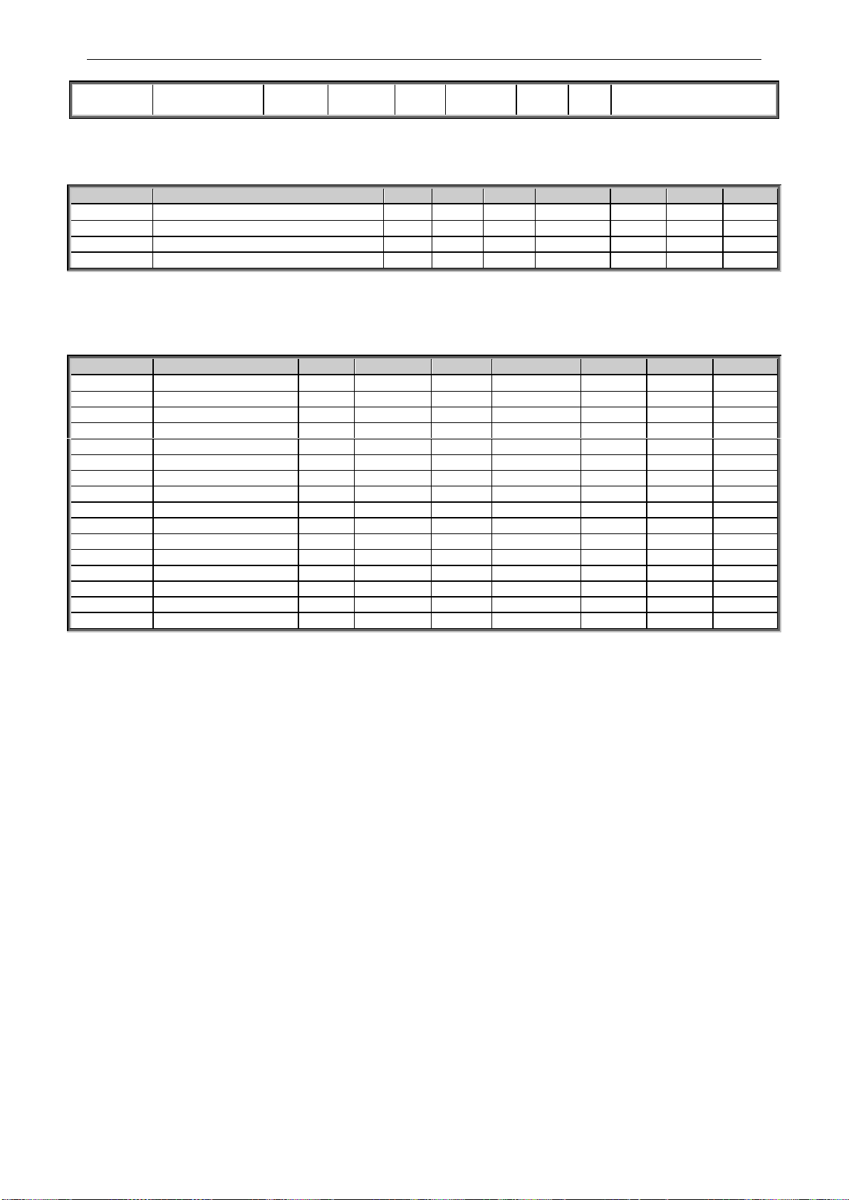
78 • VACON® apfiff20 crane control
Local contacts: http://drives.danfoss.com/danfoss-drives/local-contacts/
Classified as Public
P2.8.8.34
DeadTieContCu
rL
-3200
32000
100
175
2
Table 6-17. Identification parameters, G2.6.4
6.8.8 Fine tuning parameters
Code
Parameter
Min
Max
Unit
Default
Cust
ID
Note
P 2.8.9.1
DeadTHWCompDisab
1750
P 2.8.9.2
CurrMeasFCompTC
1554
P 2.8.9.3
CurrLimOptions
1702
P 2.8.9.4
AdConvStartShift
1701
Table 6-18. Fine tuning parameters
6.8.9 AOL Control Tuning parameters
Code
Parameter
Min
Max
Unit
Default
Cust
ID
Note
P 2.8.10.1
Freq. 0
0
3200 % 10
1684
P 2.8.10.2
Freq. 1
0
3200 % 20
1707
P 2.8.10.3
Freq. 2
0
300 % 20
1791
P 2.8.10.4
Freq. 3
0
100 % 30
635
P 2.8.10.5
MinCurrentRef
0
100 % 70
622
P 2.8.10.6
NoLoadFluxCurr
0
100 % 70
623
P 2.8.10.7
M5 StrayFluxCurr
0
100 % 55
624
P 2.8.10.8
0 Speed Current
0
250 % 125
625
P 2.8.10.9
DeltaAngleFWD
0
2500 560
692
P 2.8.10.10
DeltaAngleREV
0
2500 1536
693
P 2.8.10.11
Flux Current Kp
0
32000
5000
1708
P 2.8.10.12
Flux Current Ti
0
3200 4
1709
P 2.8.10.13
FluxStabGain1
0
32000 100
1541
P 2.8.10.14
FluxStabGainFWP
0
32000 300
1542
P 2.8.10.15
FluxStabLimit
0
32000 300
1543
P 2.8.10.16
FluxCurrentDamp
0
32000 50
1546
Table 6-19. AOL Control tuning parameters
Page 79

apfiff20 crane control 79 • VACON®
Local contacts: http://drives.danfoss.com/danfoss-drives/local-contacts/
Classified as Public
6.9 Speed Control
6.9.1 Speed Control Basic settings
Code
Parameter
Min
Max
Unit
Default
Cust
ID
Note
P2.9.1
Load drooping
0.00
100.00
%
0.00
620
P2.9.2
Load Drooping Time
0
32000
ms 0
656
For dynamic changes
P2.9.3
Load Drooping
Removal
0 2
0
1534
0=Normal
1= At zero Freq Lim
2=Linear zero to Fnom
Table 6-20. Speed control basic settings
6.9.2 Speed Control OL Settings
Code
Parameter
Min
Max
Unit
Default
Cust
ID
Note
P2.9.4.1
Speed controller
P gain (open loop)
0
32767
3000
637 P2.9.4.2
Speed controller
I gain (open loop)
0
32767 300
638
Table 6-21 Speed control OL settings
6.9.3 Speed Control CL Settings
Code
Parameter
Min
Max
Unit
Default
Cust
ID
Note
P2.9.5.1
Speed control P
gain
0
1000 30
613
P2.9.5.2
Speed control I
time
-32000
32000
ms
100
614
Negative value uses 0.1 ms
format instead of 1 ms
P2.9.5.3
0-speed time at
start
0
32000
ms
100
615
P2.9.5.4
0-speed time at
stop
0
32000
ms
100
616
P2.9.5.5
SPC f1 Point
0.00
320.00
Hz
0.00
1301 P2.9.5.6
SPC f0 Point
0.00
320.00
Hz
0.00
1300 P2.9.5.7
SPC Kp f0
0
1000 % 100
1299 P2.9.5.8
SPC Kp FWP
0
1000 % 100
1298
P2.9.5.9
SPC Torque
minimum
0
400.0 % 0.0
1296
P2.9.5.10
SPC Torque
minimum Kp
0
1000 % 100
1295
P2.9.5.11
SPC Kp TC
Torque
0
1000
ms
0
1297
Table 6-212.Speed control CL settings
6.10 Drive Control
Code
Parameter
Min
Max
Unit
Default
Cust
ID
Note
P2.10.1
Switching frequency
1.0
Varies
kHz
Varies
601
P2.10.2
Modulator Type
0 3 0
1516
P2.10.3
Control Options
0
65535 64
1084
P2.10.4
Control Options 2
0
65535 0
1798
P2.10.5
Advanced Options 1
0
65535 0
1560
P2.10.6
Advanced Options 2
0
65535 0
1561
P2.10.7
Advanced Options 4
0
65535 0
1563
P2.10.8
Advanced Options 5
0
65535 0
1564
P2.10.9
Advanced Options 6
0
65535 0
1565
P2.10.10
Restart Delay
0
65535
s
Varies
1424
P2.10.11
Restart Delay CL
0
60.000
s
Varies
672
CL and Flying Start
Table 6-22.Drive control
Page 80

80 • VACON® apfiff20 crane control
Local contacts: http://drives.danfoss.com/danfoss-drives/local-contacts/
Classified as Public
6.11 Master Follower Control Parameters
Code
Parameter
Min
Max
Unit
Default
Cust
ID
Note
P2.11.1
Master Follower
Mode
0 6
0
1324
0=Not Used
1=Master
2=Follower
3=ShaftSynch Master
4=ShaftSynch Follower
5=DriveSynch Master
6=DriveSynch Follower
P2.11.2
Follower Speed
Reference Select
0
18 17
1081
0=AI1
1=AI2
2=AI1+AI2
3=AI1-AI2
4=AI2-AI1
5=AI1xAI2
6=AI1 Joystick
7=AI2 Joystick
8=Keypad
9=Fieldbus
10=Motor potentiometer
11=AI1, AI2 minimum
12=AI1, AI2 maximum
13=Max frequency
14=AI1/AI2 selection
15=Encoder 1
16=Encoder 2
17=MSS Reference
18=Master Reference
19=Master Ramp Out
P2.11.3
Follower Torque
Reference Select
0
10 10
1083
0=Not used
1=AI1
2=AI2
3=AI3
4=AI4
5=AI1 joystick
6=AI2 joystick
7=Torque reference from
keypad, R3.5
8=FB Torque Reference
9=Master Torque OL
10=Master Torque CL
P2.11.4
Follower Stop
Function
0 2
2
1089
0=Coasting
1=Ramping
2=As Master
P2.11.5
MF Brake Logic
0 3
2
1326
Not used when Ramp
follower or in drive sync
mode
0=Master or Own
1=Own
2=Master & Own, Master
monitors also follower
brake status.
3=Master
P2.11.6
MF Mode 2
0 4 0
1093
P2.11.1
P2.11.7
System Bus Fault
0 3
1
1082
0=No response
1=Warning
2=Fault,stop acc. to 2.3.2
3=Fault,stop by coasting
P2.11.8
System Bus Fault
Delay
0.00
320.00
s
3.00
1352
P2.11.9
Follower Fault
0 3
1
1536
0=No response
1=Warning
2=Fault,stop acc. to 2.3.2
3=Fault,stop by coasting
P2.11.10
Force SB Control
0 1 0
1851
Table 6-234. Master Follower Control parameters, G2.11
Page 81

apfiff20 crane control 81 • VACON®
Local contacts: http://drives.danfoss.com/danfoss-drives/local-contacts/
Classified as Public
6.11.1.1 Drive Synch specific parameters
Code
Parameter
Min
Max
Unit
Default
Cust
ID
Note
2.11.11.1
Drive Synch Follower
fault
0 2
1531
2.11.11.2
Follower phase shift
0.0
360.0
Dec
0.0
1518
2.11.11.3
DC Voltage Blance
Gain
0
1000 100
1519
Table 6-24. Drive Synch specific parameters, G2.11.10
Page 82

82 • VACON® apfiff20 crane control
Local contacts: http://drives.danfoss.com/danfoss-drives/local-contacts/
Classified as Public
6.12 Protections
6.12.1 General settings
Code
Parameter
Min
Max
Unit
Default
Cust
ID
Note
P2.12.1.1
Input phase
supervision
0 3
0 730
0=No response
1=Warning
2=Fault,stop acc. to 2.3.2
3=Fault,stop by coasting
P2.12.1.2
Response to
undervoltage fault
0 1
0 727
0=Fault stored in history
1=Fault not stored
P2.12.1.3
Output phase
supervision
0 3
2 702
See P2.12.1.1
P2.12.1.4
Response to slot fault
0 3 2
734
See P2.12.1.1
P2.12.1.5
Safe Disable
Response
0 2
1 755
See P2.12.1.1
Table 6-255. Common settings
6.12.2 Temperature sensor protections
Code
Parameter
Min
Max
Unit
Default
Cust
ID
Note
P2.12.2.1
No. of used inputs
on board 1
0 5
0 739
0=Not used (ID Write)
1 = Sensor 1 in use
2 = Sensor 1 & 2 in use
3 = Sensor 1 & 2 & 3 in use
4 = Sensor 2 & 3 in use
5 = Sensor 3 in use
P2.12.2.2
Response to
temperature fault
0 3
2 740
0=No response
1=Warning
2=Fault,stop acc. to 2.3.2
3=Fault,stop by coasting
P2.12.2.3
Board 1 warning
limit
–30.0
200.0
Cº
120.0
741
P2.12.2.4
Board 1 fault limit
–30.0
200.0
Cº
130.0
742
P2.12.2.5
No. of uses inputs
on board 2
0 5
0 743
0=Not used (ID Write)
1 = Sensor 1 in use
2 = Sensor 1 & 2 in use
3 = Sensor 1 & 2 & 3 in use
4 = Sensor 2 & 3 in use
5 = Sensor 3 in use
P2.12.2.6
Response to
temperature fault
0 3
2 766
0=No response
1=Warning
2=Fault,stop acc. to 2.3.2
3=Fault,stop by coasting
P2.12.2.7
Board 2 warning
limit
–30.0
200.0
Cº
120.0
745
P2.12.2.8
Board 2 fault limit
–30.0
200.0
Cº
130.0
746
P2.12.2.9.1
Channel 1B Warn
-30.0
200.0
Cº
0.0
764
P2.12.2.9.2
Channel 1B Fault
-30.0
200.0
Cº
0.0
765
P2.12.2.9.3
Channel 1C Warn
-30.0
200.0
Cº
0.0
768
P2.12.2.9.4
Channel 1C Fault
-30.0
200.0
Cº
0.0
769
P2.12.2.9.5
Channel 2B Warn
-30.0
200.0
Cº
0.0
770
P2.12.2.9.6
Channel 2B Fault
-30.0
200.0
Cº
0.0
771
P2.12.2.9.7
Channel 2C Warn
-30.0
200.0
Cº
0.0
772
P2.12.2.9.8
Channel 2C Fault
-30.0
200.0
Cº
0.0
773
Table 6-26. PT-100 protections
Page 83

apfiff20 crane control 83 • VACON®
Local contacts: http://drives.danfoss.com/danfoss-drives/local-contacts/
Classified as Public
6.12.3 Stall Protection
Code
Parameter
Min
Max
Unit
Default
Cust
ID
Note
P2.12.3.1
Stall protection
0 3
0 709
0=No response
1=Warning
2=Fault,stop acc. to 2.3.2
3=Fault,stop by coasting
P2.12.3.2
Stall current
0.1
2 x IH A IH
710
P2.12.3.3
Stall time limit
1.00
120.00
s
15.00
711
P2.12.3.4
Stall frequency limit
1.0
P2.1.2
Hz
25.0
712
Table 6-27. Stall protection
6.12.4 Speed error monitoring
Code
Parameter
Min
Max
Unit
Default
Cust
ID
Note
P2.12.4.1
Speed Error Mode
0 3
0 752
0=No response
1=Warning
2=Fault,stop acc. to 2.3.2
3=Fault,stop by coasting
P2.12.4.2
Speed Error Limit
0.0
100.0 % 5.0
753
P2.12.4.3
Speed Fault Delay
0.00
100.00 S 0.1
754
P2.12.4.4
Over Sped Limit
0.00
50.00
Hz
5.00
1812
Hysteresis for over speed,
when exceeding Pos/Neg
Frequency limits
Table 6-28. Speed error monitoring
6.12.5 Motor thermal protections
Code
Parameter
Min
Max
Unit
Default
Cust
ID
Note
P2.12.5.1
Thermal
protection of the
motor
0 3
2 704
0=No response
1=Warning
2=Fault,stop acc. to 2.3.2
3=Fault,stop by coasting
P2.12.5.2
Motor ambient
temperature factor
–100.0
100.0 % 0.0
705
P2.12.5.3
Motor cooling factor
at zero speed
0.0
150.0 % 40.0
706 P2.12.5.4
Motor thermal time
constant
1
200
min
45
707
P2.12.5.5
Motor duty cycle
0
100 % 100
708
P2.12.5.6
Response to
thermistor fault
0 3
2 732
See P2.12.5.1
P2.12.5.7
Over Load
Response
0 2
1
1838
0=No response
1=Warning
2=Fault
P2.12.5.8
Over Load Signal
0 2
0
1837
0=Not Used
1=Current
2=Torque
3=Power
P2.12.5.9
Over Load
Maximum Input
0.0
300.0 % 150.0
1839
P2.12.5.10
Over Load
maximum Step
0
10000 200
1840
Table 6-29. Motor thermal protections
Page 84
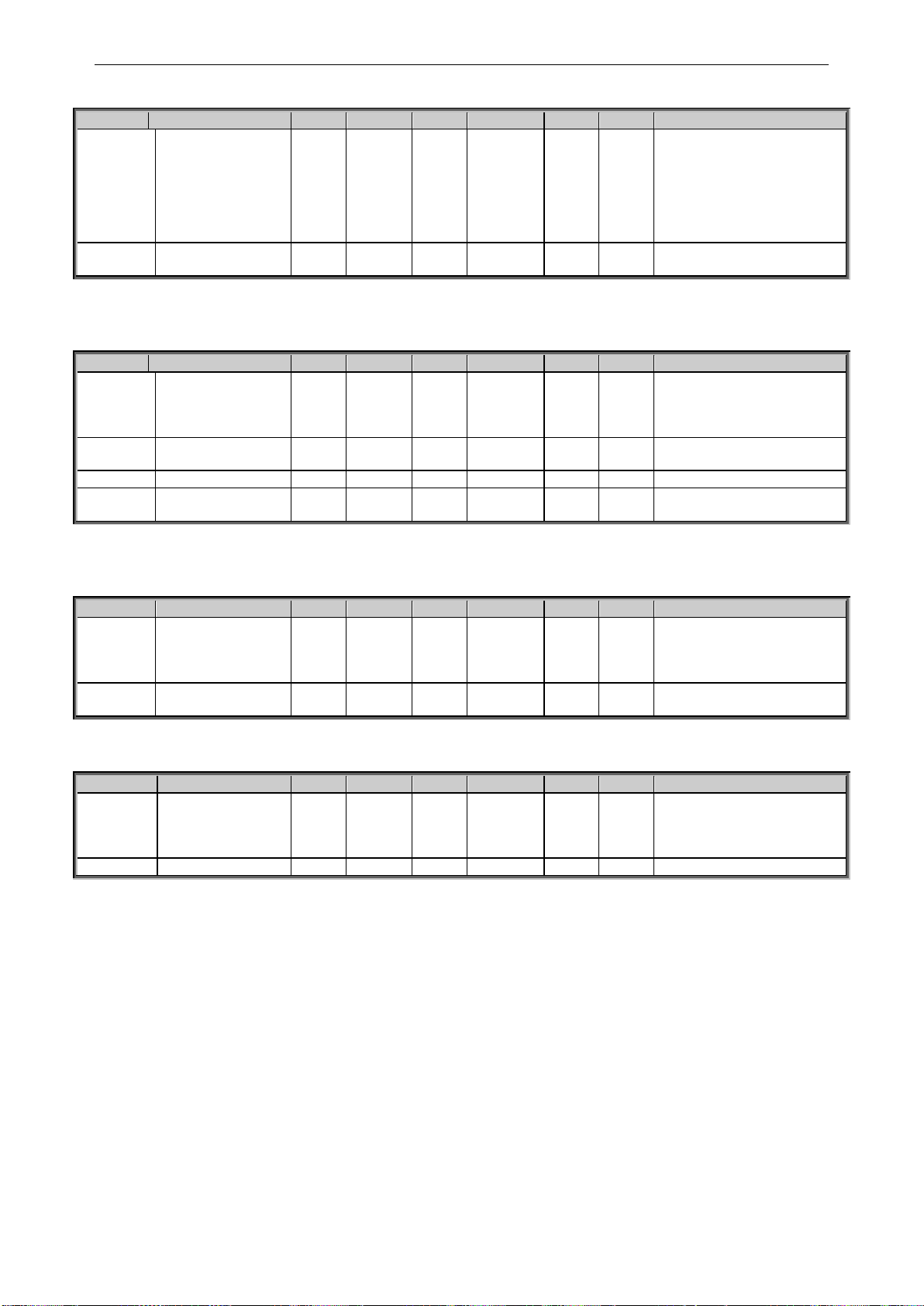
84 • VACON® apfiff20 crane control
Local contacts: http://drives.danfoss.com/danfoss-drives/local-contacts/
Classified as Public
6.12.6 Living Zero monitoring
Code
Parameter
Min
Max
Unit
Default
Cust
ID
Note
P2.12.6.1
Response to 4mA
reference fault
0 5
0 700
0=No response
1=Warning
2=Warning+Previous Freq.
3=Wrng+PresetFreq
2.12.6.2
4=Fault,stop acc. to 2.3.2
5=Fault,stop by coasting
P2.12.6.2
4mA reference fault
frequency
0.00
P2.1.2
Hz
0.00
728
Table 6-300. Living zero monitoring
6.12.7 Underload protection
Code
Parameter
Min
Max
Unit
Default
Cust
ID
Note
P2.12.7.1
Underload protection
0 3
0 713
0=No response
1=Warning
2=Fault,stop acc. to 2.3.2
3=Fault,stop by coasting
P2.12.7.2
Field weakening area
load
10.0
150.0 % 50.0
714
P2.12.7.3
Zero frequency load
5.0
150.0 % 10.0
715
P2.12.7.4
Underload
protection time limit
2.00
600.00
s
20.00
716
Table 6-31. Underload protection
6.12.8 Earth Fault protection
Code
Parameter
Min
Max
Unit
Default
Cust
ID
Note
P2.12.8.1
Earth fault protection
0 3
2 703
0=No response
1=Warning
2=Fault,stop acc. to 2.3.2
3=Fault,stop by coasting
P2.12.8.2
Eart fault current
limit
0.0
100.0 % 50.0
1333
Table 6-32.Earth fault protection
6.12.9 Cooling protection
Code
Parameter
Min
Max
Unit
Default
Cust
ID
Note
P2.12.9.1
Cooling Fault
Response
1 2
2 762
0= No Action, Warning
1= Warning, Warning
2= Warning, Fault
3= No Action, Fault
P2.12.9.2
Cooling Fault delay
0.00
7.00 s 2.00
751
Table 6-33.Cooling protection
Page 85

apfiff20 crane control 85 • VACON®
Local contacts: http://drives.danfoss.com/danfoss-drives/local-contacts/
Classified as Public
6.12.10 Fieldbus protection
Code
Parameter
Min
Max
Unit
Default
Cust
ID
Note
P2.12.10.
1
Fieldbus
Communication
response
0 3
2 733
0=No Action
1=Warning
2= Fault
3= Fault, stop by coasting
4=Warning; Prev Freq
5= Quick Stop
P2.12.10.
2
FB Fault Delay
0.00
60.00 s 0.50
1850
Delay to fault when FB
Response is 4
P2.12.10.
3
FB Watchdog Delay
0.00
30.00 s 0.00
1354
Delay when WD pulse is
missing. 0.00 s = Disabled
Table 6-34. Fieldbus protection
6.12.11 External Fault
Code
Parameter
Min
Max
Unit
Default
Cust
ID
Note
P2.12.11.
1
Response to external
fault 1
0 3
2 701
0=No response
1=Warning
2=Fault, stop acc. to 2.3.2
3=Fault, stop by coasting
P2.12.11.
2
Response to external
fault 2
0 3
2 747
0=No response
1=Warning
2=Fault, stop acc. to 2.3.2
3=Fault, stop by coasting
6.12.12 Encoder Fault
Code
Parameter
Min
Max
Unit
Default
Cust
ID
Note
P2.12.12.
1
Encoder Supervision
1 3
2
1353
1=Warning
2=Fault
3=Warning, To Open Loop
P2.12.12.
2
Encoder Fast Hz
Limit
0.00
320.00
Hz
1801
P2.12.12.
3
Fast Time Limit
0.00
32.00 s 1805
P2.12.12.
4
Iq Fault Limit
0
300 % 1800
6.12.1 Options
Code
Parameter
Min
Max
Unit
Default
Cust
ID
Note
P2.12.13
Disable Stop Lock
0 1 0
1086
P2.12.14
Reset Datalogger
0 4
0
1857
0 = Auto
1 = Reset to Auto
2 = SW Default
3 = Auto Fast
4 = No Change
P2.12.15
LDL License
0
65535 0
1993
6.13 Fieldbus parameters
Page 86

86 • VACON® apfiff20 crane control
Local contacts: http://drives.danfoss.com/danfoss-drives/local-contacts/
Classified as Public
Code
Parameter
Min
Max
Unit
Default
Cust
ID
Note
P2.13.1
Fieldbus min scale
0.00
320.00
Hz
0.00
850
P2.13.2
Fieldbus max scale
0.00
320.00
Hz
0.00
851
P2.13.3
Fieldbus process
data out 1 selection
0
10000 1
852
Choose monitoring data
with parameter ID
Def: Output Frequency
P2.13.4
Fieldbus process
data out 2 selection
0
10000 2
853
Choose monitoring data
with parameter ID
Def: Motor Speed
P2.13.5
Fieldbus process
data out 3 selection
0
10000 45
854
Choose monitoring data
with parameter ID
Def: Motor Current to FB
P2.13.6
Fieldbus process
data out 4 selection
0
10000 4
855
Choose monitoring data
with parameter ID
Def: Motor Torque
P2.13.7
Fieldbus process
data out 5 selection
0
10000 5
856
Choose monitoring data
with parameter ID
Def: Motor Power
P2.13.8
Fieldbus process
data out 6 selection
0
10000 6
857
Choose monitoring data
with parameter ID
Def: Motor Voltage
P2.13.9
Fieldbus process
data out 7 selection
0
10000 7
858
Choose monitoring data
with parameter ID
Def: DC-Link Voltage
P2.13.10
Fieldbus process
data out 8 selection
0
10000 37
859
Choose monitoring data
with parameter ID
Def: Last Active Fault
P2.13.11
Fieldbus process
data in 1 selection
0
10000
1140
876
Choose controlled data with
parameter ID.
Def: FB Torque Reference
P2.13.12
Fieldbus process
data in 2 selection
0
10000 46
877
Choose controlled data with
parameter ID.
Def: FB Limit Scaling
P2.13.13
Fieldbus process
data in 3 selection
0
10000 47
878
Choose controlled data with
parameter ID.
Def: FB Adjust Reference
P2.13.14
Fieldbus process
data in 4 selection
0
10000 48
879
Choose controlled data with
parameter ID.
Def: FB Analogue Output.
P2.13.15
Fieldbus process
data in 5 selection
0
10000 0
880
Choose controlled data with
parameter ID
P2.13.16
Fieldbus process
data in 6 selection
0
10000 0
881
Choose controlled data with
parameter ID
P2.13.17
Fieldbus process
data in 7 selection
0
10000 0
882
Choose controlled data with
parameter ID
P2.13.18
Fieldbus process
data in 8 selection
0
10000 0
883
Choose controlled data with
parameter ID
P2.13.19
General Status Word
ID
0
10000 64
897
Choose monitoring data in
General Status Word
Def: MC Status
P2.13.20
FB Actual Speed
Mode
0 1
0
1741
0=Calculated
1=Actual
P2.13.21
Control Slot Selector
0
Varies 0
1440
0=All
4=Slot D
5=Slot E
6=Slot D Fast
7=Slot E Fast
8=Slot D 16
9=Slot E 16
Note: 6-9 visible with
correct hardware and
software
Page 87

apfiff20 crane control 87 • VACON®
Local contacts: http://drives.danfoss.com/danfoss-drives/local-contacts/
Classified as Public
P2.13.22
State Machine
1 2
1
896
1 = Standard
2 = ProfiDrive
P2.13.23
FB Custom Minimum
-32000
+32000 0
898
FB Speed Reference
Minimum scaling
P2.13.24
FB Custom
Maximum
-32000
+32000
+10000
899
FB Speed Reference
Maximum Scaling
P2.13.25
Fieldbus process
data out 9
selection
0
10000 0
558
Visible with correct
hardware and software
P2.13.26
Fieldbus process
data out 10
selection
0
10000 0
559
Visible with correct
hardware and software
P2.13.27
Fieldbus process
data out 11
selection
0
10000 0
560
Visible with correct
hardware and software
P2.13.28
Fieldbus process
data out 12
selection
0
10000 0
561
Visible with correct
hardware and software
P2.13.29
Fieldbus process
data out 13
selection
0
10000 0
562
Visible with correct
hardware and software
P2.13.30
Fieldbus process
data out 14
selection
0
10000 0
563
Visible with correct
hardware and software
P2.13.31
Fieldbus process
data out 15
selection
0
10000 0
564
Visible with correct
hardware and software
P2.13.32
Fieldbus process
data out 16
selection
0
10000 0
565
Visible with correct
hardware and software
P2.13.33
Fieldbus process
data in 9
selection
0
10000 0
550
Visible with correct
hardware and software
P2.13.34
Fieldbus process
data in 10
selection
0
10000 0
551
Visible with correct
hardware and software
P2.13.35
Fieldbus process
data in 11
selection
0
10000 0
552
Visible with correct
hardware and software
P2.13.36
Fieldbus process
data in 12
selection
0
10000 0
553
Visible with correct
hardware and software
P2.13.37
Fieldbus process
data in 13
selection
0
10000 0
554
Visible with correct
hardware and software
P2.13.38
Fieldbus process
data in 14
selection
0
10000 0
555
Visible with correct
hardware and software
P2.13.39
Fieldbus process
data in 15
selection
0
10000 0
556
Visible with correct
hardware and software
P2.13.40
Fieldbus process
data in 16
selection
0
10000 0
557
Visible with correct
hardware and software
Table 6-35. Fieldbus parameters
Page 88

88 • VACON® apfiff20 crane control
Local contacts: http://drives.danfoss.com/danfoss-drives/local-contacts/
Classified as Public
6.13.1 Value Control
Code
Parameter
Min
Max
Unit
Default
Cust
ID
Note
P2.14.1.1
Control Input Signal
ID
0
10000
ID
0
1580
P2.14.1.2
Control Input Off
Limit
-32000
32000 0
1581
P2.14.1.3
Control Input On
Limit
-32000
32000 0
1582
P2.14.1.4
Control Output Off
Value
-32000
32000 0
1583
P2.14.1.5
Control Output On
Value
-32000
32000 0
1584
P2.14.1.6
Control Output Signal
ID
0
10000
ID
0
1585
P2.14.1.7
Control Mode
0 5
0
1586
0=SR ABS
1=Scale ABS
2=Scale INV ABS
3=SR
4=Scale
5=Scale INV
P2.14.1.8
Control Output
Filtering rime
0.000
32.000
s
0.000
1721
Table 6-36. Power reference input signal selection, G2.2.8
6.13.2 DIN ID Control 1
Code
Parameter
Min
Max
Unit
Default
Cust
ID
Note
P2.14.2.
1
ID Control DIN
0.1
E.10
0.1
1570
Slot . Board input No.
P2.14.2.
2
Controlled ID
0
10000
ID
0 1571
Select ID that is
controlled by digital input
P2.14.2.
3
False value
-32000
32000
0
1572
Value when DI is low
P2.14.2.
4
True value
-32000
32000
0 1573
Value when DI is high
Table 6-37. DIN ID Control parameters
6.13.3 DIN ID Control 2
Code
Parameter
Min
Max
Unit
Default
Cust
ID
Note
P2.14.3.
1
ID Control DIN
0.1
E.10
0.1
1590
Slot . Board input No.
P2.14.3.
2
Controlled ID
0
10000
ID
0 1575
Select ID that is
controlled by digital input
P2.14.3.
3
False value
-32000
32000
0
1592
Value when DI is low
P2.14.3.
4
True value
-32000
32000
0 1593
Value when DI is high
Table 6-38. DIN ID Control parameters
6.13.4 DIN ID Control 3
Code
Parameter
Min
Max
Unit
Default
Cust
ID
Note
P2.14.4.
1
ID Control DIN
0.1
E.10
0.1
1578
Slot . Board input No.
P2.14.4.
2
Controlled ID
0
10000
ID
0 1579
Select ID that is
controlled by digital input
P2.14.4.
3
False value
-32000
32000
0
1594
Value when DI is low
P2.14.4.
4
True value
-32000
32000
0 1596
Value when DI is high
Table 6-39. DIN ID Control parameters
Page 89

apfiff20 crane control 89 • VACON®
Local contacts: http://drives.danfoss.com/danfoss-drives/local-contacts/
Classified as Public
6.13.5 ID Controlled Digital Output 1
Code
Parameter
Min
Max
Unit
Default
Cust
ID
Note
P2.14.5.1
ID.Bit Free DO
0.00
2000.15
ID.Bit
0.00
1216
P2.14.5.2
Free DO Sel
0.1
E.10 0.1
1574
Table 6-40. ID Controlled Digital Output parameters, G2.3.10
6.13.6 ID Controlled Digital Output 2
Code
Parameter
Min
Max
Unit
Default
Cust
ID
Note
P2.14.6.1
ID.Bit Free DO
0.00
2000.15
ID.Bit
0.00
1386
P2.14.6.2
Free DO Sel
0.1
E.10 0.1
1574
Table 6-41. ID Controlled Digital Output parameters, G2.3.10
6.13.7 Free DIN Delay
Code
Parameter
Min
Max
Unit
Default
Cust
ID
Note
P2.14.7.1
ID.Bit Free DIN
0.00
2000.15
ID.Bit
0.00
1832
P2.14.7.2
On Delay
0.00
320.00
s
0.00
1833
P2.14.7.3
Off Delay
0.00
320.00
s
0.00
1834
P2.14.7.4
Mono Time
0.00
320.00
s
0.00
1836
P2.14.7.5
Control Out ID
0
10000 0
1835
Table 6-42. ID Controlled Digital Output parameters, G2.3.10
Page 90

90 • VACON® apfiff20 crane control
Local contacts: http://drives.danfoss.com/danfoss-drives/local-contacts/
Classified as Public
6.14 Brake Control Parameters
Code
Parameter
Min
Max
Unit
Default
Cust
ID
Note
P2.15.1
Brake Open, Direct
0.1
E.10
DigOU
T
0.1
446 P2.15.2
Brake FeedBack
0.1
E.10
DigIN
0.2
1210
Logic activate when 0.3
or greater
P2.15.3
Brake Open Delay
0.00
320.00
s
0.50
1544
Time that is required to
open the brake
P2.15.4
Brake Close Delay
0.00
320.00
s
0.50
1545
P2.15.5
Brake Open
FreqLim Open Loop
0.00
320.00
Hz
0.00
1535
Brake opening limit and
maximum reference limit
when brake is closed in
open loop.
P2.15.6
Brake OpenFreqLim
Closed Loop
0.00
320.00
Hz
0.00
1555
Brake opening limit and
maximum reference limit
when brake is closed in
closed loop.
P2.15.7
Brake Close
FreqLim Open Loop
0.00
320.00
Hz
0.00
1539
0.00 = Calculated
internally
P2.15.8
Brake Close
FreqLim Closed
Loop
0.00
320.00
Hz
0.00
1540
0.00 = Calculated
internally
P2.15.9
Brake Close/Open
Current Limit
0.00
320.00
A
0.00
1085
Brake is closed
immediately id current
goes below this value.
P2.15.10
Brake Options 1
0
65535 0
1600
Table 6-43. Brake control parameters, G2.3.9
6.14.1 Brake Control Start up torque for CL
Code
Parameter
Min
Max
Unit
Default
Cust
ID
Note
P2.15.11.
1
Start-up torque
0 3
0 621
0=Not used
1=Torque memory
2=Torque reference
3=Start-up torque fwd/rev
P2.15.11.
2
Start-up torque FWD
–300.0
300.0 s 0.0
633
P2.15.11.
3
Start-up torque REV
–300.0
300.0 s 0.0
634
P2.15.11.
4
Start Up Torque
Time
-1
10000
ms
-1
1371
-1 = Automatic
6.14.2 Roll Back Control for CL
Code
Parameter
Min
Max
Unit
Default
Cust
ID
Note
P2.15.12.
1
Roll Back Kp
-32000
32000 0
1787
P2.15.12.
2
Roll Back Torque
-3200
3200 0.0
1788
P2.15.12.
3
Roll Back Level
-32000
32000 3
1789
P2.15.12.
4
Roll Back Kp 2
-32000
32000 0
1792
Page 91
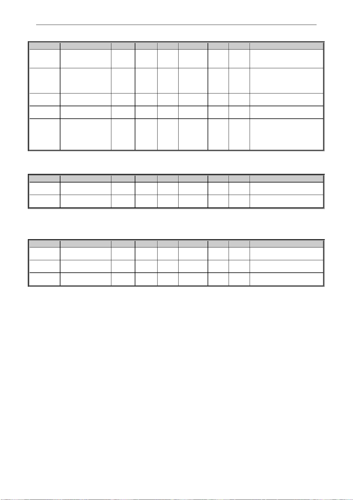
apfiff20 crane control 91 • VACON®
Local contacts: http://drives.danfoss.com/danfoss-drives/local-contacts/
Classified as Public
6.14.3 Brake Fault handling
Code
Parameter
Min
Max
Unit
Default
Cust
ID
Note
P2.15.13.
1
Brake Closed Fault
1 3
1
1316
1=Warning
2=Fault,stop acc. to 2.3.2
3=Fault,stop by coasting
P2.15.13.
2
Brake Open Fault
1 4
1 777
1=Warning
2=Fault,stop acc. to 2.3.2
3=Fault,stop by coasting
4=Warning; Start holding
P2.15.13.
3
Feed Back Open
Delay
0.00
320.0
0
s
0.00
1317
P2.15.13.
4
Feed Back Close
Delay
0.00
320.0
0
s
0.00
1733
P2.15.13.
5
Brake Slip
Response
0 4
1
1785
0=No response
1=Warning
2=Fault,stop acc. to 2.3.2
3=Fault,stop by coasting
4=Warning, Start Drive
6.14.4 Functions
Code
Parameter
Min
Max
Unit
Default
Cust
ID
Note
P2.15.14.
1
Load Floating Time
0.00
32.00 s 0.00
1282
P2.15.14.
2
StopTorqueReleTime
0
500
ms
0
1858
6.14.5 Brake Test Function
Code
Parameter
Min
Max
Unit
Default
Cust
ID
Note
P2.15.15.
1
Brake Test
0 1
0
1843
P2.15.15.
2
Testing Torque
-300
300 % 50.0
1844
P2.15.15.
3
Brake Timing Torque
Reference
-300
300 % 40.0
1849
Page 92

92 • VACON® apfiff20 crane control
Local contacts: http://drives.danfoss.com/danfoss-drives/local-contacts/
Classified as Public
6.15 Auto Reset parameters
Code
Parameter
Min
Max
Unit
Default
Cust
ID
Note
P2.16.1
Wait time
0.10
10.00 s 0.50
717 P2.16.2
Trial time
0.00
60.00 s 0.10
718
P2.16.3
Start function
0 2
2
719
0=Ramp
1=Flying start
2=According to Stop
Function
P2.16.4
Number of tries after
undervoltage trip
0
10 0
720
P2.16.5
Number of tries after
overvoltage trip
0
10 0
721 P2.16.6
Number of tries after
overcurrent trip
0 3
0
722
P2.16.7
Number of tries after
reference trip
0
10 0
723
P2.16.8
Number of tries after
motor temperature
fault trip
0
10 0
726
P2.16.9
Number of tries after
external fault trip
0
10 0
725
P2.16.10
Number of tries after
underload fault trip
0
10 0
738
P2.16.11
Fault Simulation
0
65535 0
1569
Table 6-44. Autorestart parameters, G2.16
6.16 PI Control Parameters
Code
Parameter
Min
Max
Unit
Step
Default
ID
Note
P2.17.1
PI controller gain
0.0
1000.0
% 100.0
118 P2.17.2
PI controller I-time
0.00
320.00
s 1.00
119
P2.17.3
PI Reference
-32000
32000
0
167
P2.17.4
PI controller
reference signal
ID
0
10000
167
332
Default P2.17.3
P2.17.5
PI Actual value ID
0
10000
0
333
P2.17.6
PI Controller
output ID
0
10000
0
1802
P2.17.7
PI Controller
Scale
-32000
32000
1
340
>= 1 = No inversion
<=-1 = Inverted
0 = Illegal value
P2.17.8
PI Low limit
-32000
32000
359
P2.17.9
PI High limit
-32000
32000
10000
360
P2.17.10
PI Controller
Output scale
-3200.0
3200.0
% 100.0
1803
P2.17.11
PI Stop state
value
-32000
32000
0
1806
Table 6.45. PI Controller parameters, G2.15
Page 93
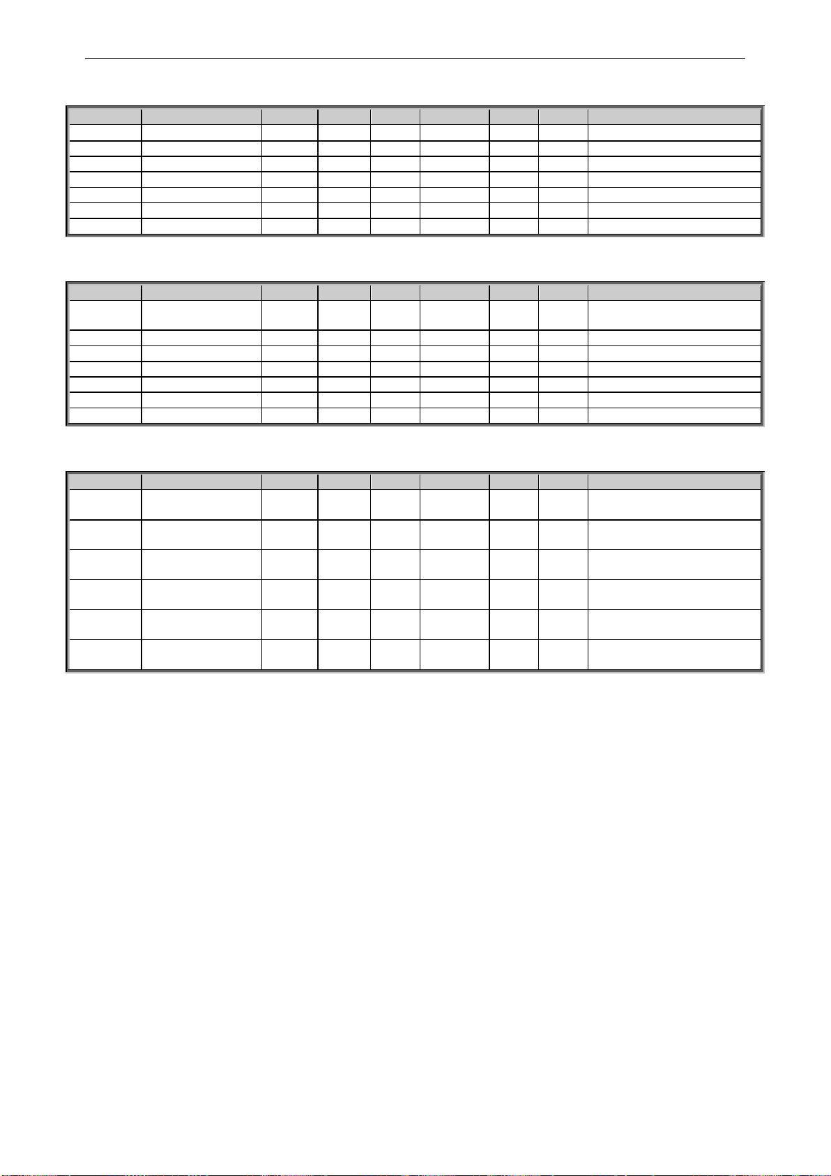
apfiff20 crane control 93 • VACON®
Local contacts: http://drives.danfoss.com/danfoss-drives/local-contacts/
Classified as Public
6.17 Shaft Synchronization
Code
Parameter
Min
Max
Unit
Default
Cust
ID
Note
P2.18.1
Enable Synch
0.1
E.10
DigIn
0.1
1816
P2.18.2
Synch Kp
0
1000 100
1817
P2.18.3
Synch Ti
0
20000
ms
500
1818
P2.18.4
MaxRefCorrection
0.00
20.00
Hz
2.00
1819
P2.18.5
ZeroErrorLimit
0
1000 10
1824
P2.18.6
Fault Limit
0
100 1
1826
0 = Disabled
P2.18.7
Reset Position
0.1
E.10 0.1
1090
6.18 Load Estimation
Code
Parameter
Min
Max
Unit
Default
Cust
ID
Note
P2.19.1
Motor Nominal
Torque
0,0
3200,
0
Nm
0,0
1906
P2.19.2
Rotor Inertia
0,0
10,0
kgm2
0,0
1907
P2.19.3
Gear Box Inertia
0,0
1000
kgm2
0,0
1908
P2.19.4
Drum Inertia
0,0
1000
kgm2
0,0
1909
P2.19.5
Gear Ratio
0,0
1000
1/x 1
1910
P2.19.6
Drum Radius
0,0
1000 m 1
1911
P2.19.7
Rope Multiply
0
100 x 1
1912
6.19 Functional Safety
Code
Parameter
Min
Max
Unit
Default
Cust
ID
Note
P2.20.1
SQS Reaction
0 1 1
545
0=No Action
1=Quick Stop
P2.20.2
SS1 Reaction
0 1 1
542
0=No Action
1=Stop
P2.20.3
SS2 Reaction
0 1 1
546
0=No Action
1=Zero Speed
P2.20.4
SDI Reaction
0 1 1
544
0=No Action
1=Disable Dir
P2.20.5
SLS Reaction
0 1 1
543
0=No Action
1=End Limit Ref
P2.20.6
SSR Reaction
0 1 1
547
0=No Action
1=Limit Speed
Page 94

94 • VACON® apfiff20 crane control
Local contacts: http://drives.danfoss.com/danfoss-drives/local-contacts/
Classified as Public
6.20 Anti-Swing Function
Code
Parameter
Min
Max
Unit
Default
Cust
ID
Note
P 2.21.1
License Key
0
65535
0
1995
P 2.21.2
Anti-Swing Mode
0 4 0
1846
0=Not used
1=Mode 1
2=Mode 2
3=Mode 3
4=Mode 4
P 2.21.3
Swinging Period
0.0
100.0
s
0.0 1743
P 2.21.4
Rope Length
0
32000
cm
0.0 1686
P 2.21.5
Smoothing TC
0
32000
ms 0
1186
P2.21.6
Disable Anti-Swing
0.1
E.10
DigIN
0.1 1853
P2.21.7
Low Speed
Positioning Run
0 5 0
1854
0=Not used
1=Mode 1
2=Mode 2
3=Mode 3
4=Mode 4
5=Mode 5
P2.21.8
Low Speed
Positioning
Maximum
Frequency
0.00
320.00
Hz
0.00
1855
P2.21.9
Rope Length
Selection
0 2 0
1918
0=Parameter
1=From Hoist
2=Own Calculation
Page 95

apfiff20 crane control 95 • VACON®
Local contacts: http://drives.danfoss.com/danfoss-drives/local-contacts/
Classified as Public
6.21 Keypad control (Control keypad: Menu M3)
The parameters for the selection of control place and direction on the keypad are listed below.
See the Keypad control menu in the VACON® NX User Manual.
Code
Parameter
Min
Max
Unit
Default
Cust
ID
Note
P3.1
Control place
1 4 2
125
0=PC Control
1=I/O terminal
2=Keypad
3=Fieldbus
4=SB Control
R3.2
Keypad reference
P2.1.1
P2.1.2
Hz
0.00
P3.3
Direction (on
keypad)
0 1 0
123
0=Forward
1=Reverse
P3.4
Stop button
0 1 1
114
0=Limited function of Stop
button
1=Stop button always
enabled
R3.5
Torque reference
0.0
100.0 % 0.0
Table 6-46. Keypad control parameters, M3
6.22 System menu (Control keypad: Menu M6)
For parameters and functions related to the general use of the AC drive, such as application and
language selection, customised parameter sets or information about the hardware and software,
see VACON® NX User Manual.
6.23 Expander boards (Control keypad: Menu M7)
The M7 menu shows the expander and option boards attached to the control board and boardrelated information. For more information, see VACON® NX User Manual.
Page 96

96 • VACON® apfiff20 crane control
Local contacts: http://drives.danfoss.com/danfoss-drives/local-contacts/
Classified as Public
7. DESCRIPTION OF PARAMETERS
7.1 Basic Parameters
P2.1.1 Maximum frequency ID102 “Max Frequency”
Defines maximum frequency limit both negative and positive directions.
Direction dependent frequency limits can be given in “G: Limit Settings \ Frequency
Handling”.
Note: When the AC drive is in run state, do not change this parameter to a value
lower than the current output frequency. The change will be executed without ramp.
P2.1.2 Motor Nominal Voltage ID110 “Motor Nom Voltg”
Find this value Un on the rating plate of the motor.
P2.1.3 Motor Nominal Frequency ID111 “Motor Nom Freq”
Find this value fn on the rating plate of the motor. This parameter sets the field
weakening point to the same value in “G: Motor Control \ U/f Settings”.
P2.1.4 Motor nominal speed ID112 “Motor Nom Speed”
Find this value nn on the rating plate of the motor. Note also nominal frequency.
In some cases, the motor nominal speed is shown with one decimal. In this case the
practice is to give nearest integer number and adjust motor nominal frequency so
that drive will calculate correct [FW]PolePairNumber.
P2.1.5 Motor nominal current ID113 “Motor Nom Currnt”
Find this value In on the rating plate of the motor. If magnetization current is provided
set also Magnetization current P2.1.9 before identification run.
DriveSynch Operation
Motor Nominal current from the motor name plate / Number of drives in parallel using
VACON® Drive Synch.
P2.1.6 Motor cos phi ID120 “Motor Cos Phi”
Find this value “cos phi” on the rating plate of the motor.
P2.1.7 Motor Nominal Power ID116 “Motor Nom Power”
Find this value on the rating plate of the motor.
Page 97

apfiff20 crane control 97 • VACON®
Local contacts: http://drives.danfoss.com/danfoss-drives/local-contacts/
Classified as Public
P2.1.8 Magnetizing current ID612 “MagnCurrent”
Set here the motor magnetizing current (no-load current).
Can be measured by running motor without load at 2/3 of nominal speed.
When value is zero the magnetization current is calculated from motor nominal
parameters, formulas below:
If given before identification run this is used as reference for U/f tuning when making
identification without rotating the motor.
P2.1.9 Identification ID631 “Identification”
Identification Run is a part of tuning the motor and the drive specific parameters. It is
a tool for commissioning and service of the drive with the aim to find as good
parameter values as possible for most drives. The automatic motor identification
calculates or measures the motor parameters that are needed for optimum motor
and speed control.
NOTE: Set motor control mode to Frequency Control before identification!
NOTE: During the identification, the AC drive will not open mechanical brake for
safety reasons. If motor rotation requires that brake is opened this needs to be
achieved externally.
NOTE: During the identification run, the torque and power limits should be above
100%. Also current limit should be above motor nominal current.
NOTE: During the identification run, the acceleration time should be below 20
seconds.
NOTE: If switching frequency is changed after the identification, we recommend you
to do the identification run again.
NOTE: A small motor with a long motor cable may require a reduction of switching
frequency if identification is not successful.
0 = “No Action” No action
No identification requested.
Page 98

98 • VACON® apfiff20 crane control
Local contacts: http://drives.danfoss.com/danfoss-drives/local-contacts/
Classified as Public
1 = “ID No Run” - Identification without rotating the motor
Current is applied to the motor but shaft will not be rotated. U/f settings are identified.
This identification is minimum requirement if motor is only to be used in open loop
control. It is however recommended to make the identification always with rotating
motor in case the closed loop control is needed after the mechanics are connected
to shaft.
Example of behaviour
Parameters updated during this identification
AM: PM:
P2.1.8 MagnCurrent P2.8.4.2 U/f Ratio Select
P2.8.4.2 U/f Ratio Select P2.8.4.5 U/f Mid Freq
P2.8.4.5 U/f Mid Freq P2.8.4.6 U/f Mid Voltg
P2.8.4.6 U/f Mid Voltg P2.8.4.7 Zero Freq Voltg
P2.8.4.7 Zero Freq Voltg P2.8.5.1 CurrentControlKp
P2.8.9.16 RsVoltageDrop P2.8.6.12 LsdVoltageDrop
P2.8.9.17 IrAddZeroPVoltag P2.8.6.13 LsqVoltageDrop
P2.8.9.22-24 Ix Offset P2.8.6.19 Curr. Contr. Kp d
P2.8.9.29 Org UF ZeroPVolt P2.8.9.16 RsVoltageDrop
P2.8.9.17 IrAddZeroPVoltag
P2.8.9.20 LsVoltageDrop
P2.8.9.22-24 Ix Offset
P2.8.9.25 Estimator Kp
P2.8.9.29 Org UF ZeroPVolt
Page 99

apfiff20 crane control 99 • VACON®
Local contacts: http://drives.danfoss.com/danfoss-drives/local-contacts/
Classified as Public
2 = “ID With Run” - Identification with motor rotating
Shaft is rotated during identification.
This identification must be run without load on motor shaft. U/f settings and
magnetization current are identified. This identification should be run regardless of
the final operation mode (closed loop or open loop) to get the best performance from
the motor. When identification with motor rotation is successfully finished the drive
starts to use internal slip estimator to compensate the motor temperature changed.
SCTorqueChainSelect B5 & B6.
Example of behaviour
Parameters updated during this identification
AM: PM:
P2.1.8 MagnCurrent P2.8.4.2 U/f Ratio Select
P2.8.4.2 U/f Ratio Select P2.8.4.3 Field WeakngPnt
P2.8.4.5 U/f Mid Freq P2.8.4.5 U/f Mid Freq
P2.8.4.6 U/f Mid Voltg P2.8.4.6 U/f Mid Voltg
P2.8.4.7 Zero Freq Voltg P2.8.4.7 Zero Freq Voltg
P2.8.9.16 RsVoltageDrop P2.8.5.1 CurrentControlKp
P2.8.9.17 IrAddZeroPVoltag P2.8.6.12 LsdVoltageDrop
P2.8.9.22-24 Ix Offset P2.8.6.13 LsqVoltageDrop
P2.8.9.29 Org UF ZeroPVolt P2.8.6.19 Curr. Contr. Kp d
P2.8.5.8 Temp.Compen.Mode P2.8.9.16
RsVoltageDrop
P2.8.9.1-15 Flux X % P2.8.9.17 IrAddZeroPVoltag
P2.8.9.20 LsVoltageDrop
P2.8.9.21 MotorBEMVoltage
P2.8.9.22-24 Ix Offset
P2.8.9.25 Estimator Kp
P2.8.9.29 Org UF ZeroPVolt
P2.8.5.8
Temp.Compen.Mode
Page 100

100 • VACON® apfiff20 crane control
Local contacts: http://drives.danfoss.com/danfoss-drives/local-contacts/
Classified as Public
3 = “Enc. ID Run” - Encoder identification run
The motor shaft is rotated during identification.
IM: If performed for induction motor encoder pulse number and direction are
identified. Can be used if the is no encoder information available, correct result can
be achieved only when motor in unloaded.
PMSM: This selection is used for PMS motor if automatic angle identification is not
suitable for used motor (angle is identified automatically in every start if PMSM Shaft
Position parameter is zero).
This identification run will update PMSM Shaft Position parameter based on absolute
position of the encoder or Z pulse position of incremental type encoder.
Note: Identification needs to be remade if encoder position related to motor is
changed e.g. due maintenance.
Parameters updated during this identification
AM: PM:
P2.1.8 MagnCurrent P2.8.6.1 PMSMShaftPositio
P2.8.4.2 U/f Ratio Select P2.8.9.22-24 Ix Offset
P2.8.4.5 U/f Mid Freq P2.8.9.25 Estimator Kp
P2.8.4.6 U/f Mid Voltg
P2.8.4.7 Zero Freq Voltg
P2.8.9.16 RsVoltageDrop
P2.8.9.17 IrAddZeroPVoltag
P2.8.9.22-24 Ix Offset
P2.8.9.29 Org UF ZeroPVolt
P2.8.5.8 Temp.Compen.Mode
P2.8.9.1-15 Flux X %
P7.3.1.2 Pulse revolution
P7.3.1.3 Invert direction
 Loading...