

Page 1

vacon
®
nx
ac drives
apfiff10 sia-i
System Interface
application manual
Page 2

Page 3

apfiff10 sia-i VACON® • 3
Local contacts: http://drives.danfoss.com/danfoss-drives/local-contacts/
System Interface Application
INDEX
Document code: ud01079
Software Code: APFIFF10V244
Date: 24.4.2019
1. INTRODUCTION .............................................................................................................. 5
2. CONTROL I/O ................................................................................................................. 6
3. SYSTEM INTERFACE APPLICATION PARAMETER LISTS ................................................ 7
3.1 Monitoring Values .......................................................................................................................... 7
3.1.1 Monitor Page 1 ....................................................................................................................... 8
3.1.2 Monitor Page 2 ....................................................................................................................... 8
3.1.3 PI-Controller Monitoring ...................................................................................................... 9
3.2 Basic Parameters ........................................................................................................................ 10
3.3 Input Signals ................................................................................................................................ 11
3.3.1 Digital Input .......................................................................................................................... 11
3.3.2 Analogue Input ..................................................................................................................... 12
3.4 Output Signals .............................................................................................................................. 13
3.4.1 Digital Output ....................................................................................................................... 13
3.4.2 Analogue Output .................................................................................................................. 14
3.5 Reference Handling ..................................................................................................................... 14
3.6 Ramp Functions ........................................................................................................................... 16
3.7 Drive Control ................................................................................................................................ 17
3.7.1 Drive Control/Open Loop Ctrl ............................................................................................. 18
3.7.2 Drive Control/UV/OV CTRL stab ......................................................................................... 19
3.8 Motor Control ............................................................................................................................... 20
3.8.1 PMSM Control ...................................................................................................................... 21
3.9 Limit Settings ............................................................................................................................... 22
3.10 Speed Control............................................................................................................................... 23
3.11 Oscillation Damp .......................................................................................................................... 24
3.12 Brake & Fan Control .................................................................................................................... 25
3.13 Master Follower ........................................................................................................................... 26
3.14 Protections ................................................................................................................................... 27
3.15 Flux Reference Handling ............................................................................................................. 29
3.16 Startup Torque ............................................................................................................................. 29
3.17 Monitor Settings ........................................................................................................................... 29
3.18 Data Mapping ............................................................................................................................... 30
3.19 PI Control Parameters ................................................................................................................ 30
3.19.1 Connect DIN -> ID 1 ......................................................................................................... 31
3.19.2 Connect DIN -> ID 2 ......................................................................................................... 31
3.19.3 Connect DIN -> ID 3 ......................................................................................................... 31
3.19.4 Value Control ................................................................................................................... 32
3.20 Keypad Control ............................................................................................................................. 32
3.21 Expander Boards ......................................................................................................................... 32
Page 4

4 • VACON® apfiff10 sia-i
Local contacts: http://drives.danfoss.com/danfoss-drives/local-contacts/
4. DESCRIPTION OF THE SYSTEM INTERFACE APPLICATION PARAMETERS ..................... 33
4.1 Input Signals ................................................................................................................................ 35
4.1.1 Digital Input .......................................................................................................................... 35
4.1.2 Analogue Input ..................................................................................................................... 39
4.1.3 Digital Output ....................................................................................................................... 41
4.1.4 Analogue output................................................................................................................... 41
4.2 Reference Handling ..................................................................................................................... 42
4.3 Ramp Functions ........................................................................................................................... 44
4.4 Drive Control ................................................................................................................................ 46
4.4.1 Open Loop Control ............................................................................................................... 51
4.4.2 Undervoltage/Overvoltage Control, Stabilator .................................................................. 53
4.5 Motor Control ............................................................................................................................... 55
4.6 PMSM Control .............................................................................................................................. 59
4.7 Limit Settings ............................................................................................................................... 60
4.8 Speed control ............................................................................................................................... 62
4.9 Oscillation Damp .......................................................................................................................... 67
4.10 Brake and fan control .................................................................................................................. 67
4.11 Master Follower ........................................................................................................................... 68
4.12 Protections ................................................................................................................................... 71
4.13 Flux Reference Handling ............................................................................................................. 79
4.14 Startup Torque ............................................................................................................................. 80
4.15 Monitor Settings ........................................................................................................................... 81
4.16 Data Mapping ............................................................................................................................... 81
4.17 PI Control...................................................................................................................................... 82
4.18 ID Functions ................................................................................................................................. 83
4.18.1 Value Control ................................................................................................................... 84
5. FIELDBUS PROFILE ...................................................................................................... 86
5.1 PD Signals from the Overriding system to the Vacon Drive. .................................................... 86
5.2 PD Signals from the Vacon Drive to the Overriding System ..................................................... 86
5.3 Main Control Word ID1160 .......................................................................................................... 87
5.4 Main Status Word ID1162 ............................................................................................................ 88
5.5 Auxiliary Control Word ID1161 .................................................................................................... 89
5.6 Auxiliary Status Word ID1163 ...................................................................................................... 90
5.7 Fault Word 1 ID1172 .................................................................................................................... 91
5.8 Fault Word 2 ID1173 .................................................................................................................... 92
5.9 Alarm Word 1 ID1174 ................................................................................................................... 93
5.10 Digital Input Status 1 and 2: ID15 and ID16 ................................................................................ 94
6. BLOCK DIAGRAMS ................................................................ ........................................ 95
7. FAULT TRACING ......................................................................................................... 100
Page 5

apfiff10 sia-i VACON® • 5
Local contacts: http://drives.danfoss.com/danfoss-drives/local-contacts/
System Interface Application (apfiff10 sia-i)
1. INTRODUCTION
The System Interface Application is typically used in coordinated drives with overriding control
system. The recommended interface to control the system is a fieldbus communication through
hardwired analogue and digital signals as well as keypad and PC control can be used.
Note! When the drive is controlled through fieldbus, the fieldbus card must be set to Bypass mode.
The System Interface Application utilises most advanced functions in NXP motor control software
and is suitable for demanding drive systems like paper machines and drives in metal industry and
processing lines. It can also be used for any other standard applications. Following applications are
working with this application.
• Pulp and paper machine drives like dryer, press section, wire section, pope reel, winder and
unwinder.
• Drives in metal industry like casting machine, melt shop or preparing line
• Standard drives like pump and fan, lifts, cranes, conveyors, etc.
Additional functions:
• Flexible speed and torque reference chains.
• Advanced drive control profile for fieldbus communication
• Flexible fieldbus data connections.
• Adaptive speed controller.
• Inertia compensation and oscillation damping features.
• System Bus support for master follower applications with speed/torque follower.
• Fast and multi drive monitoring tool (NCDrive) support.
• Programmable U/f curve and flux curve.
• Speed /torque-selector options, window control
• Automatic identification run
• Support to permanent magnet motors and multiple winding motors.
Page 6
6 • VACON® apfiff10 sia-i
Local contacts: http://drives.danfoss.com/danfoss-drives/local-contacts/
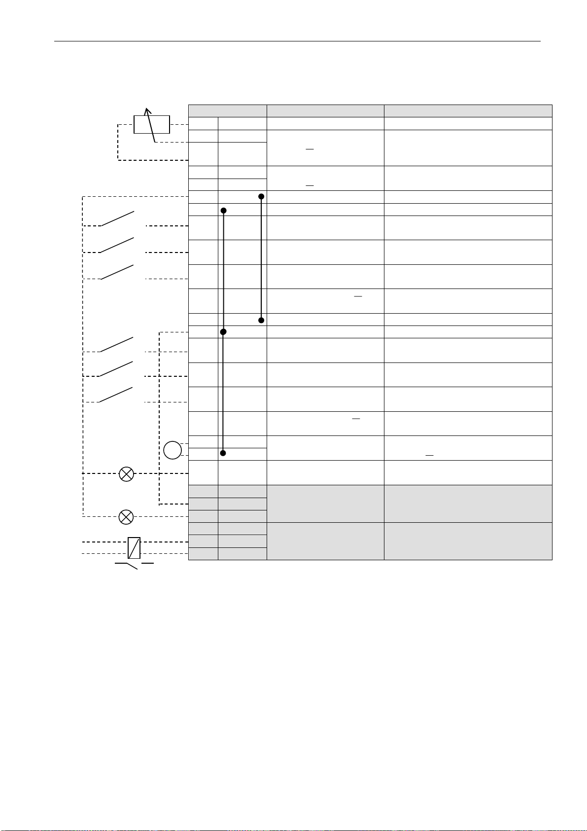
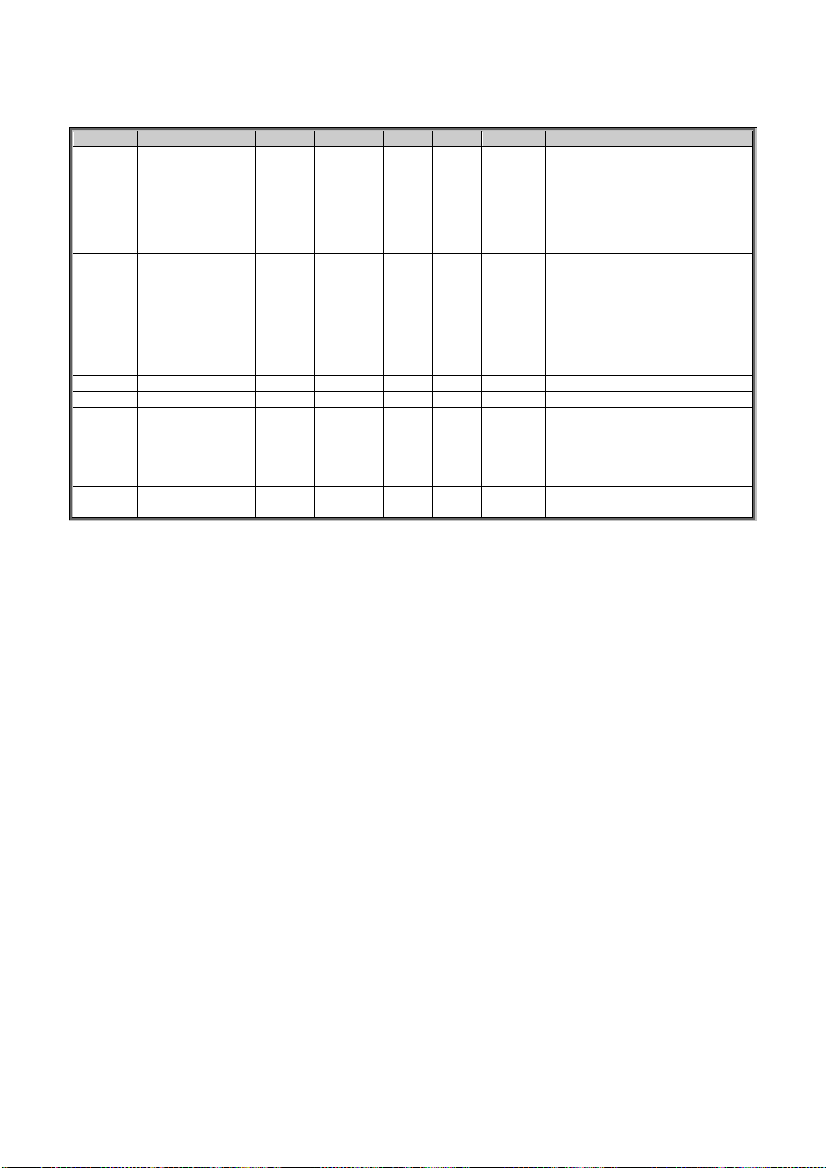
2. CONTROL I/O
Terminal
Signal
Description
1
+10V
Reference output
Voltage for potentiometer, etc.
2
AI1+
Analogue input, voltage
range 0 10V DC
Voltage input frequency reference
3
AI1-
4
AI2+
Analogue input, current
range 0 20mA
Current input frequency reference
5
AI2-
6
+24V
Control voltage output
Voltage for switches, etc. max 0.1 A
7
GND
I/O ground
Ground for reference and controls
8
DIN1
Digital input 1
(Programmable)
9 DIN2
Digital input 2
(Programmable)
10
DIN3
Digital input 3
(programmable)
11
CMA
Common for DIN 1
DIN 3
Connect to GND or +24V
12
+24V
Control voltage output
Voltage for switches (see #6)
13
GND
I/O ground
Ground for reference and controls
14
DIN4
Digital input 4
Run Enable
Contact closed = Run Enable
Contact open =Run Disable
15
DIN5
Digital input 5
Main Switch Ack.
Contact closed = Switch is closed.
Contact open= Switch is open.
16
DIN6
Digital input 6
Emergency Stop
Contact open= EmstopActive.
Contact closed = Emstop not active.
17
CMB
Common for DIN4
DIN6
Connect to GND or +24V
18
AOA1+
Programmable
Programmable
Range 0 20 mA/RL, max. 500
19
AOA1-
20
DOA1
Digital output
READY
Programmable
Open collector, I50mA, U48 VDC
21
RO1
Relay output 1
RUN
Programmable
22
RO1
23
RO1
24
RO2
Relay output 2
DC bus Charging OK
Programmable
25
RO2
26
RO2
Table 1. System Interface Application default I/O configuration.
mA
READY
RUN
220
Page 7

apfiff10 sia-i VACON® • 7
Local contacts: http://drives.danfoss.com/danfoss-drives/local-contacts/
3. SYSTEM INTERFACE APPLICATION PARAMETER LISTS
On the next pages you will find the lists of monitoring signals and parameters. The parameter
descriptions are given on pages 33 to 81.
Column explanations:
Code = Location indication on the keypad; Shows the operator the present parameter
number
Parameter = Name of parameter
Min = Minimum value of parameter
Max = Maximum value of parameter
Unit = Unit of parameter value; given if available
Step = Accuracy of smallest possible change of value
Default = Value preset by factory
ID = ID number of the parameter (used with PC tools)
3.1 Monitoring Values
The monitoring values are the actual values of parameters and signals as well as statuses and
measurements. See Vacon NX User's Manual, Chapter 7 for more information.
Page 8
8 • VACON® apfiff10 sia-i
Local contacts: http://drives.danfoss.com/danfoss-drives/local-contacts/
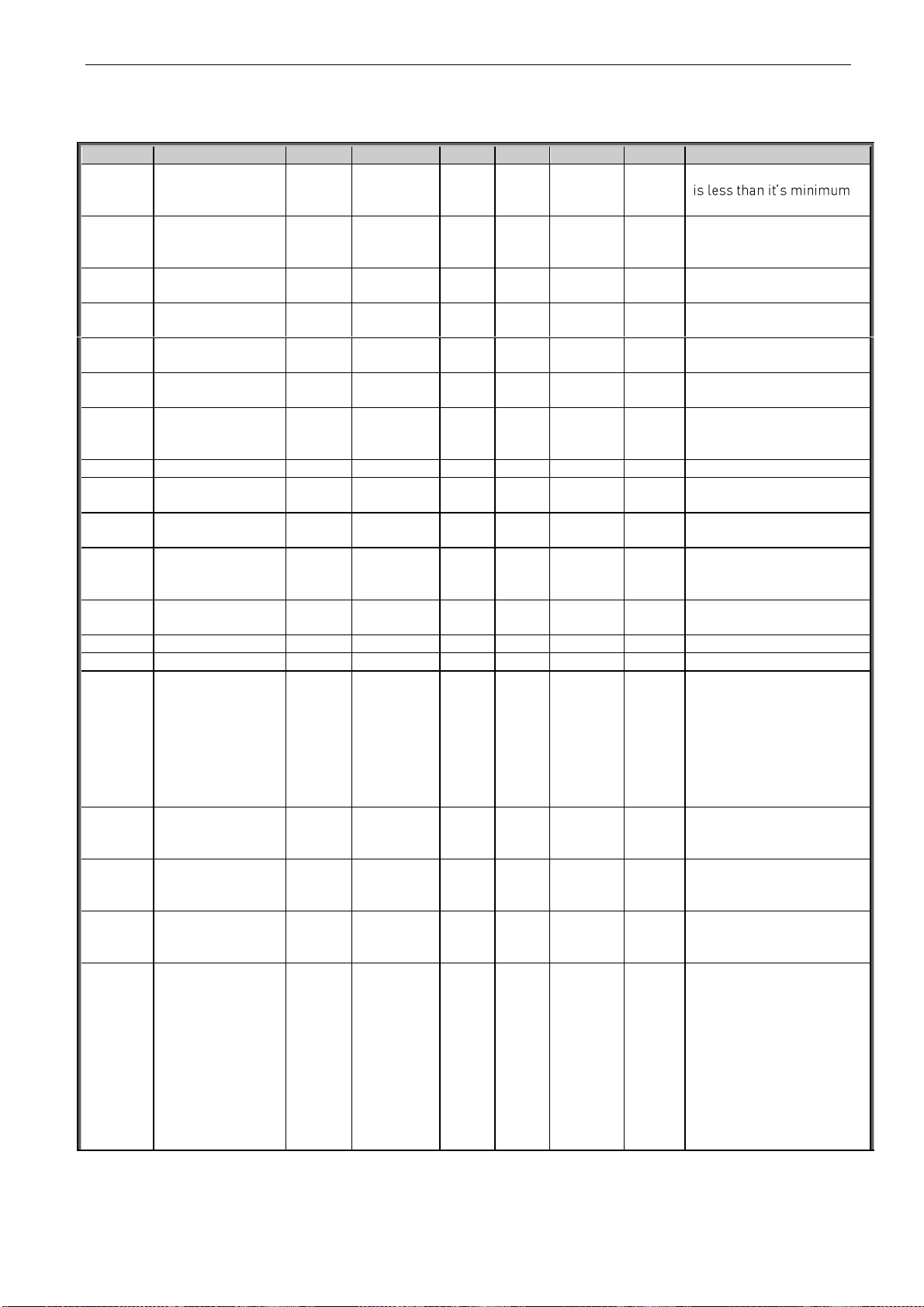
3.1.1 Monitor Page 1
Code
Parameter
Unit
ID
Description
V1.1.1
Output frequency
Hz
1
Frequency output from the drive to the motor.
V1.1.2
Speed
Rpm
2
Motor speed in rpm. In open loop this is the calculated speed
of the motor and in closed loop this is the filtered value of the
speed measured from the encoder.
V1.1.3
Freq. Reference
Hz
25
Frequency reference to the ramp generator.
V1.1.4
Current A 3
Filtered motor current.
V1.1.5
Torque % 4
Filtered motor torque in percentage of motor nominal torque.
V1.1.6
Power % 5
Power in percentage of motor nominal power.
V1.1.7
Motor voltage
V
6
Motor terminal voltage.
V1.1.8
DC-link voltage
V
7
DC link voltage.
V1.1.9
Unit tempertaure
°C
8
Heat sink temperature.
V1.1.10
DIN Status Word1
15
See the chapter 5.10
V1.1.11
DIN Status Word2
16
See the chapter 5.10
V1.1.12
MotorTempCalc
%
9
Calculated motor temperature .
100.0% = nominal temperature of the motor.
V1.1.13
Temp sensor 1
°C
50
Temperature of the PT100 or KTY 84 type temperature sensor
1 connected to Analogue input. If OPT-B8 board is used then
this value shows temperature of channel 1.
V1.1.14
Temp sensor 2
°C
51
Temperature of the PT100 or KTY 84 type temperature sensor
2 connected to Analogue input. If OPT-B8 board is used then
this value shows temperature of channel 2.
V1.1.15
Temp sensor 3
°C
52
If OPT-B8 board is used for temperature measurement then
this value shows temperature of channel 3.
V1.1.16
Unit nom. voltage
V
1117
Nominal voltage rating of the drive unit.
V1.1.17
Unit nom. current
A
1118
Nominal current rating of the drive unit. This is same as IL
current rating of the unit.
V1.1.18
DC nom. voltage
V
1120
Nominal DC link voltage of the drive unit.
V1.1.19
ID Run status
49
Bitwise status of automatic identification after ID run.
B0= Stator resistance and U/f curve
B1= Reserved
B2= Magnetisation current.
B3= Flux linearization curve.
V1.1.20
Analogue Input 1
%
59
Filtered A.1
V1.1.21
Analogue Input 2
%
60
Filtered A.1
Table 2. Monitoring page 1
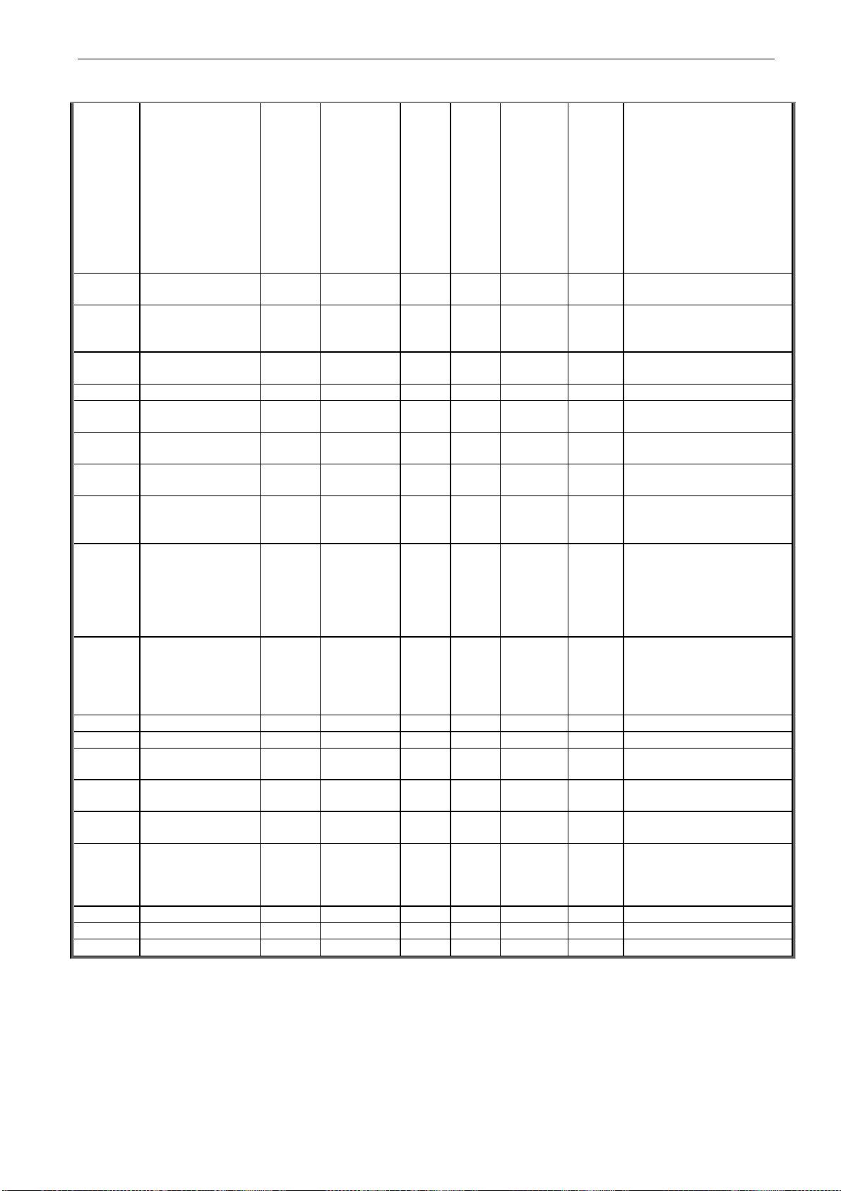
3.1.2 Monitor Page 2
Code
Parameter
Unit
ID
Description
V1.2.1
Speed Measured
rpm
1124
Speed measured from the encoder.
V1.2.2
Torque Unfilt.
%
1125
Unfiltered torque calculated by the drive.100% equals to motor
nominal torque.
V1.2.3
Current Unfilt.
%
1113
Unfiltered Motor current in Amperes.
V1.2.4
Speed Reference1
rpm
1126
Speed reference selected as per the control place selection.
V1.2.5
Speed Reference2
rpm
1127
Speed reference after speed share logic.
V1.2.6
Speed Reference3
rpm
1128
Speed reference at the input of the ramp generator.
V1.2.7
Speed Ramp Out
rpm
1129
Final speed reference after Ramp generator
V1.2.8
Speed Reference4
rpm
1130
Speed reference after the speed correction is added to the
Speed Ramp Out. 1)
V1.2.9
Used Speed Ref
rpm
1131
Final speed reference after the speed step logic. 1)
V1.2.10
Speed Error
rpm
1132
Speed error=Speed Act Speed Ref 1)
V1.2.11
SPC OUT
%
1134
Iq Reference from the speed controller output. 1)
V1.2.12
SPC Out P-part
%
1866
Speedcontroller monitoring P-part separately
V1.2.13
SPC Out I-part
%
1865
Speedcontroller monitoring I-part separately
V1.2.14
Speed Limit Pos
rpm
1135
Positive speed limit on the speed reference
V1.2.15
Speed Lim Neg
rpm
1136
Negative speed limit on the speed reference
Page 9
apfiff10 sia-i VACON® • 9
Local contacts: http://drives.danfoss.com/danfoss-drives/local-contacts/
Code
Parameter
Unit
ID
Description
V1.2.16
TC Speed Lim Pos
rpm
1137
Positive speed limit when Torque Select is 2/3/4/5 and Motor
Ctrl Mode =3.
V1.2.17
TC Speed Lim Neg
rpm
1138
Negative speed limit when Torque Select is 2/3/4/5 and Motor
Ctrl Mode =3.
V1.2.18
Master TorqueRef
%
1139
Torque reference from Master Drive in case of master
Follower comm.
-300.0....+300.0% of the motor nominal torque
V1.2.19
FB Torque Ref
%
1140
Torque Reference from the Fieldbus.
-300.0...300.0%. of motor nominal torque
V1.2.20
I/0 Torque Ref
%
1141
Torque Reference from the analogue Input
-300.0...300.0%. of motor nominal torque
V1.2.21
Torque Ref1
%
1142
Torque reference after Torque Reference selector (Master,
Fieldbus, analogue I/P)
V1.2.22
Torque Ref2
%
1143
Scaled Torque Reference
V1.2.23
Torque Ref3
%
1144
Torque reference after Load Share logic.
V1.2.24
Used Torque Ref
%
1145
Final, limited torque reference for speed/torque controller
V1.2.25
Acc Comp Out
%
1146
Acceleration compensation used in terms of
IqReference.100.0% equals to motor nominal current. 1)
V1.2.26
Droop Speed RPM
rpm
1147
Speed droop used in rpm.
V1.2.27
Startup TorqAct
A
1148
startup torque in use, 100.0 %= motor nominal torque.
V1.2.28
Iq Current Lim +
%
1152
Final upper IqCurrentLimit 100.0 %= motor nominal current
(unsigned)
V1.2.29
Iq Current Lim -
%
1153
Final lower IqCurrentLimit 100.0 %= motor nominal current
(unsigned)
V1.2.30
Iq Reference
%
1154
Final IqReference, 100.0% = motor nominal current
V1.2.31
Iq Actual
%
1155
Measured Iq 100.0% = motor nominal current
V1.2.32
Id Reference
%
1156
Final IdReference 100.0% = motor nominal current
V1.2.33
Id Actual
%
1157
Measured Id 100.0 %= motor nominal current.
V1.2.34
Flux % 1158
Estimated rotor flux in percentage of the motor nominal flux.
V1.2.35
Rotor t Const
ms
1159
Rotor Time Constant in ms
V1.2.36
Main Control Word
1160
V1.2.37
Aux Control Word1
1161
See the chapter 5.5
V1.2.38
Main Status Word
1162
See the chapter 5.4
V1.2.39
Aux Status Word
1163
See the chapter 5.6
V1.2.40
Fault Word 1
1172
See the chapter 5.7
V1.2.41
Fault Word 2
1173
See the chapter 5.8
V1.2.42
Alarm Word 1
1174
See the chapter 5.9
V1.2.43
Shaft Position
1169
Position of the motor
V1.2.44
Shaft Rounds
1170
No. of rounds of the motor shaft.
V1.2.45
Pole Pair Number
58
Number of pole pairs in the motor estimated from the motor
data.
V1.2.46
Output power
1508
Drive output power
V1.2.47
Last active fault
37
Code of the last active fault
Table 3. Monitoring page 2
3.1.3 PI-Controller Monitoring
Code
Parameter
Unit
ID
Description
V1.3.1
PI Reference value
20
PI controller reference value
V1.3.2
PI Actual value
21
PI Controller actual value
V1.3.3
PI Controller output
23
PI Controller output before output scaling
V1.3.4
PI Controller output
scaled
1807
PI Controller output after output scaling. This is the value that
is written to values selected by P2.18.6
Table 4. PI-Controller monitoring page
Page 10

10 • VACON® apfiff10 sia-i
Local contacts: http://drives.danfoss.com/danfoss-drives/local-contacts/
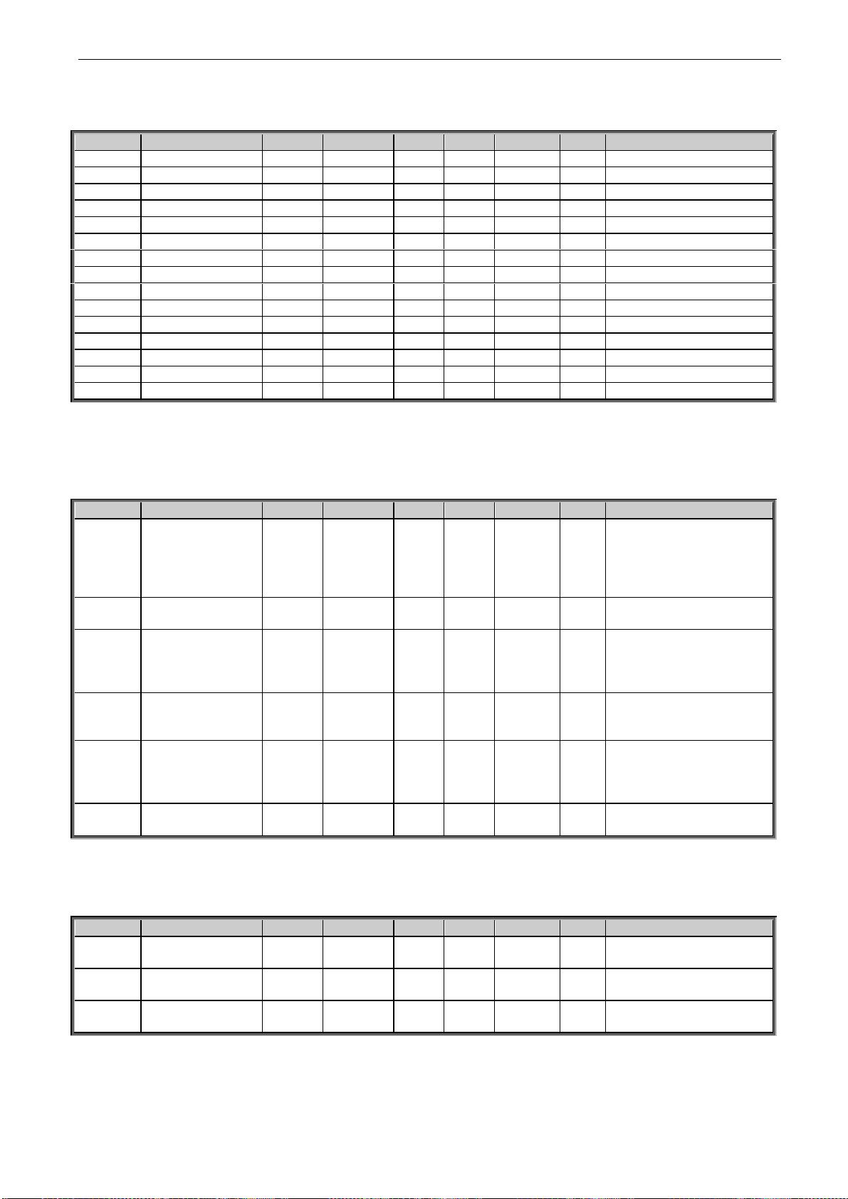
3.2 Basic Parameters
Code
Parameter
Min
Max
Unit
Step
Default
ID
Note
P2.1.1
Supply Voltage
0
1000 V 1
500
1201
Supply Voltage in Volts. If
unknown then parameter
should be zero.
P2.1.2
Motor Nominal
Voltage
180
690 V 1
400
110
Nominal Voltage of the
Motor in volts as per
Rating Plate
P2.1.3
Motor Nominal
Frequency
30.00
320.00
Hz
0.01
50.00
111
Nominal Frequency of the
Motor ##. ## Hz as per
Rating Plate
P2.1.4
Motor Nominal
Current
0,01 * I
H
2 * IH
A
0.1
IH
113
Nominal Current of the
Motor. in ####.# A
P2.1.5
Motor Nominal
Speed
300
ns rpm 1 1440
112
Nominal Speed of the
Motor as per Rating Plate
P2.1.6
Motor Cos Phi
0.30
1.00
0.01
0.85
120
Rated value of cos phi as
per Rating Plate
P2.1.7
Process Speed
0.0
3200.0
rpm
0.1
14400
1203
Process Speed limit in
RPM scale
P2.1.8
Magn. Current
0.0
Motor
Nom
Current
A
0.1
0.5
612
Nominal magnetizing
current of the motor in
amps (Current Format)
P2.1.9
Field Weakng Pnt
8.00
320.00
Hz
0.01
50.00
602
Frequency at which Field
Weakening should start.
Applicable only in Open
Loop Control
P2.1.10
Voltage at FWP
5.00
200.00
%
0.01
100.00
603
Motor Voltage Limit in
Field weakening.
Applicable only in Open
Loop Control
P2.1.11
ID Run
0 4 1 0
631
Automatic Identification
run for the motor.
0 = None
1 = Identification without
motor running.
2 = Identification with
motor running.
3 = Encoder ID
4 = Magnetisation current
calculation
P2.1.12
Motor Type
0 3 1 0
650
Motor type
0= Induction motor
1= Not Used
2= Permanent magnet
motor
3= Not Used
Table 5. Basic parameters G2.1
Page 11
apfiff10 sia-i VACON® • 11
Local contacts: http://drives.danfoss.com/danfoss-drives/local-contacts/
3.3 Input Signals
3.3.1 Digital Input
Code
Parameter
Min
Max
Unit
Step
Default
ID
Note
P2.2.1.1
Run Forward
0
Max. No
of DIN
installed
1 0
1206
Digital input selection for the
Run Forward command when
the Control Place=IO control.
P2.2.1.2
Run Reverse
0
Max. No
of DIN
installed
1 0
1207
Digital input selection for Run
Reverse command when the
control place=IO control
P2.2.1.3
IO Ctrl
0
Max. No
of DIN
installed
1 0
1404
Digital input selection to
activate the IO control.
P2.2.1.4
Reset
0
Max. No
of DIN
installed
1 0
1208
Digital input Selection for
Fault Resetting.
P2.2.1.5
Brake Open
0
Max. No
of DIN
installed
1 0
1210
Input Selection for Acknowledgement of Motor Mechanical Brake. Off=Brake
Closed, On=Brake Opened.
P2.2.1.6
Brake Open Logic
0 1 1 0
1379
The connection type for brake
open acknowledgement.
0= Normally Open.
1= Normally closed.
P2.2.1.7
Motor Fan Ack.
0
Max. No
of DIN
installed
1 0
1211
Input selection for Motor Fan
Acknowledgement. If no
acknowledgement for 1 Sec
after Fan On command then
Alarm F56 ``Motor Fan``
P2.2.1.8
Input Switch Ack
0
Max. No
of DIN
installed
1 5
1209
Input selection for input
switch acknowledgement.
If not acknowledged then
P2.2.1.9
Run Enable
0
Max. No
of DIN
installed
1 4
1212
Input selection For Run Enable. If input is missing then
P2.2.1.10
Run Enable Logic
0 1 1 0
1380
Connection type for Run
Enable.
0= Normally Open
1= Normally closed.
P2.2.1.11
Emstop
0
Max. No
of DIN
installed
1 6
1213
Input For Emergency Stop.
Low=Emergency stop Active
P2.2.1.12
External Fault
0
Max. No
of DIN
installed
1 0
1214
Digital input selection for
External Fault signal
connection.
P2.2.1.13
Ext. Fault Logic
0 1 1 0
1381
Connection type for external
fault input connection.
0= Normally open
1= Normally closed.
P2.2.1.14
Motor 1 Or 2 Sel
0
Max. No
of DIN
installed
1 0
1215
Select parameter set for
Motor 1 or Motor 2 with the
selected digital input.
High=Motor2.Low=Motor1
P2.2.1.15
PI Activation
-1
Max. No
of DIN
installed
1 0
1804
When HIGH PI Controller is
activated.
-1 = Forced ON
Table 6. Digital Input parameters, G2.2.1
Page 12

12 • VACON® apfiff10 sia-i
Local contacts: http://drives.danfoss.com/danfoss-drives/local-contacts/
3.3.2 Analogue Input
Code
Parameter
Min
Max
Unit
Step
Default
ID
Note
P2.2.2.1
I/O SpeedRef Sel
0 5 1 0
1219
Analogue Input selection
for Speed reference when
Control Place=1 (IO ctrl)
P2.2.2.2
I/O TorqRef Sel
0 3 1 0
1220
Analogue Input selection
for Torque reference
when Control Place=1
(Local IO Control)
P2.2.2.3
TS 1 AI Sel
0 2 1 0
1221
Analogue Input selection
for PT100 or KTY 84 type
temperature sensor 1.
P2.2.2.4
TS 1 Sel
0 2 1 0
1222
Number of PT100 or KTY
84 elements in series.
0=1*PT100,
1=2*PT100,
2=3*PT100.
3=1*KTY84-130
4=2*KTY84-130
5=3*KTY84-130
P2.2.2.5
TS 2 AI Sel
0 2 1 0
1223
Analogue Input selection
for PT100 or KTY 84 type
temperature sensor 2.
P2.2.2.6
TS 2 Sel
0 2 1 0
1224
Number of PT100
elements in series.
0=1*PT100,
1=2*PT100,
2=3*PT100.
3=1*KTY84-130
4=2*KTY84-130
5=3*KTY84-130
P2.2.2.7
AI1 Ref Scale
Min
-30000
30000
1 0
1226
Min. value of signal selected for AI1. This corresponds to
+0V/0mA/2V/4mA
P2.2.2.8
AI1 RefScale
Max
-30000
30000
1 1440
1225
Max. value of signal selected for AI1. This corresponds to +10V/20mA
P2.2.2.9
AI1 Minimum
0 1 1 0
1227
Minimum voltage or
Current at AI1.
0=0V/0mA, 1=4mA
P2.2.2.10
AI1 Filter Time
0.01
10.00
s
0.01
1
1228
Filter time for AI1 in ###.
## Sec
P2.2.2.11
AI2 RefScale Min
-30000
30000
1 0
1230
Min. Value of Signal selected for AI2.This corresponds to
+0V/0mA/2V/4mA
P2.2.2.12
AI2 RefScale
Max
-30000
30000
1 1000
1229
Max. Value of Signal selected for AI2.This corresponds to +10V/20mA
P2.2.2.13
AI2 Minimum
0 1 1 0
1231
Minimum Voltage or Current at AI2.0=0V/0mA,
1=4mA
P2.2.2.14
AI2 Filter Time
0.01
10.00
s
0.01
1
1232
Filter time for AI2 in ###.
## Sec.
Table 7. Analogue Input parameters, G2.2.2
Page 13

apfiff10 sia-i VACON® • 13
Local contacts: http://drives.danfoss.com/danfoss-drives/local-contacts/
3.4 Output Signals
3.4.1 Digital Output
Code
Parameter
Min
Max
Unit
Step
Default
ID
Note
P2.3.1.1
DO1 (ID.BitNo.)
0.00
2000.15
0.01
1162.00
1216
Select the signal for
controlling DO1.
P2.3.1.2
DO2 (ID.BitNo.)
0.00
2000.15
0.01
1162.00
1217
Select the signal for
controlling DO2
P2.3.1.3
DO3 (ID.BitNo.)
0.00
2000.15
0.01
1163.00
1218
Select the signal for
controlling DO3.
P2.3.1.4
DO4 (ID.BitNo.)
0.00
2000.15
0.01
0000.00
1385
Select the signal for
controlling DO4.
P2.3.1.5
DO5 (ID.BitNo.)
0.00
2000.15
0.01
0000.00
1386
Select the signal for
controlling DO5.
P2.3.1.6
DO6 (ID.BitNo.)
0.00
2000.15
0.01
0000.00
1390
Select the signal for
controlling DO6.
P2.3.1.7
DO7 (ID.BitNo.)
0.00
2000.15
0.01
0000.00
1391
Select the signal for
controlling DO7.
P2.3.1.8
DO8 (ID.BitNo.)
0.00
2000.15
0.01
0000.00
1395
Select the signal for
controlling DO8.
P2.3.1.9
DO9 (ID.BitNo.)
0.00
2000.15
0.01
0000.00
1396
Select the signal for
controlling DO9.
P2.3.1.10
DO10 (ID.BitNo.)
0.00
2000.15
0.01
0000.00
1423
Select the signal for
controlling DO10.
P2.3.1.11
DO11 (ID.BitNo.)
0.00
2000.15
0.01
0000.00
1427
Select the signal for
controlling DO11.
P2.3.1.12
DO12 (ID.BitNo.)
0.00
2000.15
0.01
0000.00
1428
Select the signal for
controlling DO12.
P2.3.1.13
DO13 (ID.BitNo.)
0.00
2000.15
0.01
0000.00
1429
Select the signal for
controlling DO13.
Table 8 Digital Output parameters, G2.3.1
Page 14

14 • VACON® apfiff10 sia-i
Local contacts: http://drives.danfoss.com/danfoss-drives/local-contacts/
3.4.2 Analogue Output
Code
Parameter
Min
Max
Unit
Step
Default
ID
Note
P2.3.2.1
AO1 Signal ID
0
2000
1 0
1233
Set the ID no. Of a signal
to be connected to AO1.
P2.3.2.2
AO1 Offset
0 1 1 0
1234
Minimum voltage or current at AO1.
0= OV/0mA.
1= 2V/4mA
P2.3.2.3
AO1 Filter
0.02
10.00
S
0.01
10.00
1235
Filter time for AO1
P2.3.2.4
AO1 Max Value
-30000
30000
1 1500
1236
Maximum value of the signal selected for AO1. This
will correspond to +10V/
20mA.
P2.3.2.5
AO1 Min Value
-30000
30000
1 0
1237
Minimum value of the signal selected for AO1. This
will correspond to 0V/0mA
or 2V/4mA depending on
AO1 Offset.
P2.3.2.6
AO1 Adjust
-200,00
200,00
0,01
0,00
375
Table 9 Analogue output parameters, G2.3.2
3.5 Reference Handling
Code
Parameter
Min
Max
Unit
Step
Default
ID
Note
P2.4.1
Spd Ref Filter
0
5000
ms 1 0
324
Filter time for the speed
reference in ms
P2.4.2
Const Ref 1
P2.8.4
P2.8.3
rpm 1 0
1239
Constant speed reference 1.
Normally used for forward
inching
P2.4.3
Const Ref 2
P2.8.4
P2.8.3
rpm 1 0
1240
Constant speed reference 2.
Normally used for reverse
inching
P2.4.4
CriticalSpeedLow
0
Max_
Speed
Rpm 1 0
509
Low limit for critical speed
range
P2.4.5
CriticalSpeedHigh
0
Max_
Speed
Rpm 1 0
510
High limit for critical speed
range
P2.4.6
Speed Share
-300.00
300.00
%
0.01
100.00
1241
Speed share as percentage
of speed reference.
P2.4.7
FBRef Scale
10
30000
1 20000
1242
This will correspond to
P2.1.7 (Process Speed).
P2.4.8
Tref Source Sel
0 4 1 0
641
Source for the torque
reference.
0=None
1=Master
2=Fieldbus
3=Analogue I/P
4=Master SPC
P2.4.9
Tref Filter
0
5000
ms 1 0
1244
Filter time for the torque
reference in ms
P2.4.10
Tref Hysteresis
-300.0
300.0
%
0.1
0.0
1245
Hysteresis for the torque
reference in ####.#
%.100.0% ~motor nominal
torque.
P2.4.11
Tref Dead Zone
-300.0
300.0
%
0.1
0.0
1246
Dead zone in % where the
torque reference will be
considered as zero. 100.0%
~motor nominal torque.
Page 15

apfiff10 sia-i VACON® • 15
Local contacts: http://drives.danfoss.com/danfoss-drives/local-contacts/
Code
Parameter
Min
Max
Unit
Step
Default
ID
Note
P2.4.12
TorqueRef Scale
0 1 1 0
1247
The scale for the torque
reference chain and all
signals related to torque.
0 = 1000 corresponds to
motor nominal torque.
1 = 10000 corresponds to
motor nominal torque
P2.4.13
Load Share
0.0
400.0
%
0.1
100.0
1248
Load share for the torque
reference in %.
P2.4.14
Tref Ramp Time
0.0
30000
ms 1 0
1249
The ramp time in ms for
nominal torque reference
change.
P2.4.15
Flux Reference
10.0
150.0
%
0.1
100.0
1250
Flux reference in %.100%
equals rated flux of the
drive.
P2.4.16
Above Spd Limit
0
P2.8.3
rpm 1 0
1251
The speed limit above which
bit10 of the status word will
be TRUE
P2.4.17
Speed Step
-2000
2000
1 0
1252
Step speed ref. relative to
process speed. 20000 =
P2.1.7 Process speed
P2.4.18
Torque Step
-300.0
300.0
%
0.1
0.0
1253
Torque step in % of nom.
torque of the motor
P2.4.19
Speed Ref
Interpolator TC
0
32000
ms 1 10
1184
Table 10 Ref Handling parameters, G2.4
Page 16

16 • VACON® apfiff10 sia-i
Local contacts: http://drives.danfoss.com/danfoss-drives/local-contacts/
3.6 Ramp Functions
Code
Parameter
Min
Max
Unit
Step
Default
ID
Note
P2.5.1
Accel Time 1
0.0
3000.0
s
0.1
10.0
103
Acceleration Time in sec
P2.5.2
Decel Time 1
0.0
3000.0
s
0.1
10.0
104
Deceleration Time in sec
P2.5.3
S Ramp AccDec
0
100 % 1 0 500
Smooth ratio for S curves
for Acceleration and
Deceleration ramp.
0=Linear Ramps
100=Full Acc/Dec inc/dec
times.
P2.5.4
Emstop Ramp
0.0
3000.0
s
0.1
10.0
1256
Deceleration time in
Emergency Stop
P2.5.5
Emstop Delay
0.00
320.00
s
0.01
0
1254
Delay in activation of
emergency stop ramp
after emergency stop is
active
P2.5.6
ConstSpd
AccTime
0.0
3000.0
s
0.1
5.0
1257
Acceleration time for
Constant Speed 1 and 2
P2.5.7
ConstSpd
DecTime
0.0
3000.0
s
0.1
5.0
1258
Deceleration time for
Constant Speed 1 and 2
P2.5.8
S Ramp Const Spd
0
100 % 1 0 1259
Smooth ratio for S-curves
of Const Speed ramp
0=Linear ramps
100=Full Acc/Dec inc/dec
0=linear ramps
100=full acc/dec inc/dec
times
P2.5.9
Ramp Time
Reference
0 1 1 0
1132
P2.5.10
Open loop
emergency stop
limit ramp time
0
3000,0
s
0,1
1,0
1610
Table 11 Ramp Function parameters, G2.5
Page 17

apfiff10 sia-i VACON® • 17
Local contacts: http://drives.danfoss.com/danfoss-drives/local-contacts/
3.7 Drive Control
Code
Parameter
Min
Max
Unit
Step
Default
ID
Note
P2.6.1
Control Place
0 2 1 1 2
125
Place to control the drive
operation.
0=FieldBus
1=IO
2=Panel/ PC Tool
P2.6.2
Brake Chopper
0 3 1 0
504 Brake chopper mode
selection.
P2.6.3
BrkChopper Level
0
1500
V
1
1.15*nom
DC Volt
1267
Brake chopper operation
level in volts
P2.6.4
Brk Res Load Lim
0.0
300.0
%
0.1
5.0
1268
Generator side torque
limit to avoid overheating
of the brake resistor during continuous braking.
This is active when Brake
Chopper is selected and
there is no emergency
stop active and drive is
not decelerating.
G2.6.5
Open Loop Control
See table on next page
G2.6.6
UV/OV Control
See table two pages down
P2.6.7
Restart Delay
0.000
60.000
s
0.001
1424
After coast stop the restarting of the drive is
disabled for this time.
P2.6.8
ControlOptions
0
65535
1 0
1084
This packed bit word is
made for enabling/
disabling different control
options.
P2.6.9
ControlSlotSel
0 8 1 0
1440
Selects which slot
process data is used
0 = All
4 = Slot D
5 = Slot E
6 = Fast comm. Slot D
7 = Fast comm. Slot E
P2.6.10
Modulator Type
0 3 1 1
1516
0 = Hardware
1 = Software 1
2 = Software 2 (DS)
3 = Software 3
P2.6.11
Advanced Options 1
0
65535
1 0
1560
P2.6.12
Advanced Options 2
0
65535
1 0
1561
P2.6.13
Advanced Options 4
0
65535
1 0
1563
P2.6.14
Advanced Options 5
0
65535
1 0
1564
P2.6.15
Advanced Options 6
0
65535
1 0
1565
Table 12 Drive Control parameters, G2.6
Page 18

18 • VACON® apfiff10 sia-i
Local contacts: http://drives.danfoss.com/danfoss-drives/local-contacts/
3.7.1 Drive Control/Open Loop Ctrl
Code
Parameter
Min
Max
Unit
Step
Default
ID
Note
P2.6.5.1
U/f Ratio Select
0 3 1 0
108
U/F ratio selection.
0=Linear
1=Squared
2=Programmable
3=Linear + Flux opt
P2.6.5.2
U/f Zero Point V
0.00
105.00
%
0.01
0.00
606
Motor voltage (%*Motor
Nominal Voltage) at programmable U/F curve zero
point .
P2.6.5.3
U/f Mid Point V
0.00
105.00
%
0.01
100.00
605
Motor voltage (%*Motor
Nominal Voltage) at programmable U/F curve
middle point
P2.6.5.4
U/f Mid Freq
0.00
320.00
Hz
0.01
50.00
604
Programmable U/F curve
middle point
P2.6.5.5
U/f Opt.
0 1 1 0
109
U/F opt. control
P2.6.5.6
DC Brake
Speed
0
MotorNom
Speed
rpm 1 0
515
Below this speed DC
braking will be active.
P2.6.5.7
DC Brake
Current
0
2 * IH
A
507
DC Braking current
P2.6.5.8
DC Brake Time
0
20000
ms 1 0
508
P2.6.5.9
Flux Brake
0 1 1 0
520
Flux braking control
0 = Disable
1 = Enable
P2.6.5.10
FluxBrakeCurr
ent
0
2 * IH
A 0
519
Flux braking current
P2.6.5.11
TorqStab Kp
0
1000
1
1412
Gain for torque stabilator
P2.6.5.12
TorqStab Damp
TC
0
1000
1
1413
Damping time constant for
torque stabilator
P2.6.5.13
TorqStab Kp
FWP
0
1000
1
1414
Gain for torque stabilator
at FWP
P2.6.5.14
Flux Stab Kp
0
32000
1
1410
Gain for flux stabilator
P2.6.5.15
Flux Stab Filt
0
32000
1
1411
Filter time constant for
flux stabilator
P2.6.5.16
Make Flux
Time
0.000
60.000
s
0.001
0.200
660
Time to magnetise the
motor
P2.6.5.17
MakeFluxVolta
ge
0.00
120.00
%
0.01
2.01
661
Magnetising voltage in
###.## % of motor
nominal voltage.
P2.6.5.18
MeasRsVolt
Drop
0
65535
1 0
662
Measured voltage drop at
stator resistance between
two phases with nominal
current of the motor. This
is estimated during ID
Run.
P2.6.5.19
Ir Add Zero
Point Voltage
0
30000
664
Table 13 Drive Control/Open Loop Ctrl parameters, G2.6.5
Page 19

apfiff10 sia-i VACON® • 19
Local contacts: http://drives.danfoss.com/danfoss-drives/local-contacts/
3.7.2 Drive Control/UV/OV CTRL stab
Code
Parameter
Min
Max
Unit
Step
Default
ID
Note
P2.6.6.1
Undervolt Ctrl
0 1 1 0
608
Under voltage controller
0=Off, 1=On.
P2.6.6.2
Uvolt Ref Sel
0 1 1 1
1260
Selection of under voltage
Reference for Undervoltage Controller.
0=UV ref min
1=0.8*
EstimatedDCNomVoltage
P2.6.6.3
Undervolt Kp
0
32767
1
1415
Gain for the P term of
Under voltage controller
P2.6.6.4
Undervolt Ti
0
32767
1
1416
Gain for I term of under
voltage controller
P2.6.6.5
Over volt Ctrl
0 2 1 0
607
Over voltage controller
0=Off,
1=On with no Ramp,
2=On with ramp.
P2.6.6.6
Overvolt Ref Sel
0 2 1 1
1262
Overvoltage reference
level depending on the
status of the brake
chopper
P2.6.6.7
OverVolt Kp
0
32767
1
1468
Gain for P term of overvoltage controller
P2.6.6.8
OverVolt Kp Add
0
32767
1
1425
Addition gain for P term of
overvoltage controller till
FWP.
P2.6.6.9
OverVolt Ti
0
32767
1
1409
Gain for I term of the overvoltage controller.
P2.6.6.10
VoltStab Kp
0
1000
1
1417
Gain for the voltage
stabilator
P2.6.6.11
VoltStab TC
0
1000
1
1418
Damping rate for the
voltage stabilator.
Table 14. Drive Control/UV/OV Ctrl, Stab Parameters, G2.6.6
Page 20

20 • VACON® apfiff10 sia-i
Local contacts: http://drives.danfoss.com/danfoss-drives/local-contacts/
3.8 Motor Control
Code
Parameter
Min
Max
Unit
Step
Default
ID
Note
P2.7.1
Start Function
0 1 1 0
505
0=Starts from 0-speed,
1=Flying start
P2.7.2
Stop Function
0 1 1 0
506
0=Coast stop
1=Ramp stop
P2.7.3
Emstop Mode
0 3 1 1
1276
Stop function in Emergency Stop
0=Coast Stop
1=Ramp stop
2=Torque limit Stop
3=Constant Power Stop
P2.7.4
Motor Ctrl Mode
0 3 1 0
600
0=Open Loop Freq ctrl,
1=Open Loop Speed crtl
2=Open Loop speed
/torque ctrl as per P2.7.5
3=Closed Loop speed/
torque Control as per
P2.7.5
P2.7.5
Torque Select
1 5 1 1
1278
1=Speed Control
2=Torque Control
3=Min of torque ref and
SPC Out
4=Max of torque ref and
SPC Out
5=Window Control
P2.7.6
CurrentControlKp
1
10000
1 4000
617
Current controller p-gain
(0 ... 10000)
P2.7.7
CurrentControlTi
0.1
100.0
ms
0.1
1.5
1400
Current controller
integrator time constant
(0 ... 1000) = 0...100.0 ms
P2.7.8
Switching Freq
1.0
Switching
FreqMax
KHz
0.1 601
Switching frequency.
P2.7.9
Dynamic Damp Kp
0.00
100.00
%
0.01
0
1406
Dynamic damping gain
when parameter 2.7.5
Torque Select is greater
than 1. 1.00 means nominal torque for nominal
speed difference.
P2.7.10
Dynamic Damp TC
0
32000
ms 1 0
1407
Bandpass filter time constant for dynamic damping. 0 means static damping proportional to frequency error.
P2.7.11
DC Magn Current
0.0
Motor
Nom
Current
A
627
Constant DC Magnetization Current
P2.7.12
DC Magn Time
0
10000
ms 1 0
628
Constant DC magn. time
[ms] in ramp start
P2.7.13
Start 0Speed Time
0
32000
ms 1 100
615
Time of zero speed ref at
start in ms, (0 ...32000)
P2.7.14
Stop 0SpeedTime
0
32000
ms 1 100
616
Time of zero speed ref at
ramp stop in ms, (0
...32000)
P2.7.15
Stop State Flux
0
150.0
% 1 100.0
1401
The % of rated flux maintained after the motor is
stopped for the time Flux
Off Delay.
P2.7.16
Flux Off Delay
-1
32000
s 1 0
1402
The time in seconds for
which the flux will be
maintained in the motor.
Page 21

apfiff10 sia-i VACON® • 21
Local contacts: http://drives.danfoss.com/danfoss-drives/local-contacts/
Code
Parameter
Min
Max
Unit
Step
Default
ID
Note
Setting this value to 1
will keep the Stop State
Flux continuously.
P2.7.17
MotTempCompen
0 3 1 0
1426
Motor temperature
compensation.
0= Disabled
1= From TS1 temp
2= From TS2 temp.
3= Internal
P2.7.18
Modulation Index
0
200 % 1
100
655
Table 15. Motor control parameters, G2.7
3.8.1 PMSM Control
Code
Parameter
Min
Max
Unit
Step
Default
ID
Note
P2.7.18.1
Flux Control Kp
0.00
320.00
%
0.01
5.00
651
Gain for the flux
controller in %.
P2.7.18.2
Flux Control Ti
0.0
100.0
ms
0.1
5.0
652
Integral time constant for
flux current controller in
ms.
P2.7.18.3
RsIdentification
0 1 1 0
654
Stator resistance
identification during every
start.
0 = Disabled
1 = Enabled.
P2.7.18.4
Modulation
Index
0
200 % 1
100
655
Modulation index in % for
closed loop operation.
P2.7.18.5
EncAngleOffset
0
65535
1 0
649
Low word of (endat) encoder angle corresponding to shaft 0 position.
This parameter is only for
monitoring and back up
purpose. It is used only
with absolute encoders .
P2.7.18.6
Encoder Zero
position
identification
mode
0 2 0
1691
0 = Automatic
1 = Forced
2 = On Power UP
P2.7.18.7
Start
positioning
current
0,0
200,0
% 50,0
1601
P2.7.18.8
Polarity pulse
current
0,0
200,0
% 0,0
1602
P2.7.18.9
Ls Voltage Drop
0
3000
512
673
P2.7.18.10
Motor BEM
Voltage
0,00
320,00
%
0,01
90,00
674
P2.7.18.11
Estimator Kp
0
3000
1 400
1781
Table 16. PMSM control parameters, G2.7.17
Page 22

22 • VACON® apfiff10 sia-i
Local contacts: http://drives.danfoss.com/danfoss-drives/local-contacts/
3.9 Limit Settings
Code
Parameter
Min
Max
Unit
Step
Default
ID
Note
P2.8.1
Zero Speed Level
0
Motor
NomSpeed
rpm 1 15
1283
Speed below which Bit 11
of Auxiliary Status Word
becomes TRUE
P2.8.2
Zero Speed Mon
0 1 1 1
1284
Monitoring of Zero speed
is based on
0=Speed Ref,
1=Speed Actual
P2.8.3
Speed Maximum
-10000
10000
rpm 1 1440
1285
Maximum limit of the
Speed reference
P2.8.4
Speed Minimum
-10000
10000
rpm 1 0
1286
Minimum Limit for the
Speed Reference
P2.8.5
Current Limit
0,01 * IH
2 * IH
A
0.1 107
Maximum Total Current
Limit.
P2.8.6
Torque Limit Mot
0.0
300.0
%
0.1
300.0
1287
Torque limit for the
motoring side.
P2.8.7
Torque Limit Gen
0.0
300.0
%
0.1
300.0
1288
Torque limit for the
generator side.
P2.8.8
SPC OUT Limit
0.0
300.0
%
0.1
300.0
1382
Absolute maximum limit
for the speed controller
output in closed loop
control in % of motor
nominal torque.
P2.8.9
Power Limit Mot
0.0
300.0
%
0.1
300.0
1289
Power limit for motor
side
P2.8.10
Power Limit Gen
0.0
300.0
%
0.1
300.0
1290
Power limit for generator
side
P2.8.11
PullOutTorque
0.0
1000.0
%
0.1
250.0
1291
Pull Out Torque limit of
the motor
P2.8.12
System Inertia
0
30000
kgm2 1 0
1292
Inertia of the system in
kgm2.
P2.8.13
Max Brake Power
0.000
30.000
kW
0.00
1
0.000
1293
Max Braking Power Limit
in Constant Power
Emergency Stop
P2.8.14
Max Braking Torq
1
30000
Nm 1 1
1294
Max Braking Torque of
the motor in Constant
Power Emergency Stop
Table 17 Limit setting parameters, G2.8
Page 23

apfiff10 sia-i VACON® • 23
Local contacts: http://drives.danfoss.com/danfoss-drives/local-contacts/
3.10 Speed Control
Code
Parameter
Min
Max
Unit
Step
Default
ID
Note
P2.9.1
SPC Kp
1
1000
1 30
613
Speed controller P gain (0
P2.9.2
SPC Ti
0
32000
ms 1 300
614
Speed controller integrator time constant
0...32000ms
P2.9.3
Kp Min
0
100
% 1 100
1295
Relative gain (%)of SPC Kp
if torque is below P2.9.4
P2.9.4
Min Point
0
100.0
%
0.1
0.0
1296
Torque Limit for adaptive
SpeedControl_Kp (1000 =
nominal)
P2.9.5
Min Filt
0
1000
ms 1 0
1297
Filtering TC for Speed
Control_Kp in ms
P2.9.6
SPC Kp FWP
1
200
% 1 100
1298
Relative final gain of speed
controller at field weakening in % of SPC Kp.
<100 reduces gain,
>100 increases gain above
FWP
P2.9.7
SPC Kp N0
0
100
% 1 100
1299
Relative gain (%) below
SPC Kp N0 Point Init:=100
P2.9.8
N0 Point
P2.8.4
P2.8.3
rpm 1 0
1300
Below this speed N0 the
speed controller gain will
be SPC Kp N0
P2.9.9
N1Point
P2.8.4
P2.8.3
rpm 1 0
1301
Above this speed N1 speed
controller gain will be SPC
Kp
P2.9.10
Mech AccComp
TC
0.00
300.00
s
0.01
0.00
1302
Mechanical time constant
for acceleration compensation in Sec (0...300 s)
P2.9.11
Accel Comp Filt
0
1000
ms 1 0
1303
Filter time constant for
Acceleration compensation in ms
P2.9.12
LoadDrooping
0.00
100.00
%
0.01
0.00
620
Load Drooping = 0 ...
100.00% of nominal speed
at nominal torque
P2.9.13
Drooping Time
0.00
327.67
s
0.01
0.00
656
Load drooping time in ms.
Value 0 means static or
continuous drooping.
P2.9.14
Window Pos RPM
0
P2.1.5
rpm 1 0
1304
Window width in RPM for
positive direction
P2.9.15
Window Neg RPM
0
P2.1.5
rpm 1 0
1305
Window width in RPM for
negative direction
P2.9.16
Window Off Pos
0
P2.9.14
rpm 1 0
1306
Window OFF limit in RPM
for hysteresis in Window
ctrl in positive direction
P2.9.17
Window Off Neg
0
P2.9.15
rpm 1 0
1307
Window OFF limit in RPM
for hysteresis in Window
ctrl in Negative direction
P2.9.18
Slip Adjust
0
500
% 1 100
619
Slip adjust 0...500%
P2.9.19
Speed Error Filt
0
1000
ms 1 0
1311
Filter time for the speed
error
P2.9.20
Speed Act Filter
0.0
250.0
ms
0.1
0.0
1308
Filter time for the measured speed from the
encoder.
P2.9.21
SpeedErrLowPass
F
-3200,0
3200,0
Hz
0,1
0,0
1185
Speed error LP filter cutoff
frequency.
P2.9.22
AntiSwinLowPasT
C
-32000
32000
ms 1 0
1186
Lowpass time constant for
second order Antiswing
lowpass filter.
Page 24

24 • VACON® apfiff10 sia-i
Local contacts: http://drives.danfoss.com/danfoss-drives/local-contacts/
Code
Parameter
Min
Max
Unit
Step
Default
ID
Note
P2.9.23
AntiSwingGain
-32000
32000
% 1 100
1187
Gain for Antiswing function
in % to optimize step
response
P2.9.24
AntiSwingTC
-32000
32000
ms 1 0
1188
BandStop/swinging time
constant in ms for
AntiSwing control to
reduce swinging and/or
speed overshoot.
P2.9.25
Speed controller
P gain (CL)
0
32767
3000
637 P2.9.26
Speed controller
I gain (OL)
0
32767
300 638
P2.9.27
Load Drooping
Removal
0 2
0 1534
0=Normal
1= At zero Freq Lim
2=Linear zero to Fnom
Table 18 Speed control parameters, G2.9
3.11 Oscillation Damp
Code
Parameter
Min
Max
Unit
Step
Default
ID
Note
P2.10.1
Oscill Damp Sel
0 2 1 0
1310
Resonance damper
selector
0 = Not in Use
1 = BandPass
2 = BandStop + BandPass
P2.10.2
Oscill Freq
0.0
450.0
Hz
0.1
0.0
1313
Resonance damper
natural frequency
1.0...450.0 Hz
0 = Not in use
P2.10.3
Oscill Damp Gain
0.0
100.0
%
0.1
0.0
1314
Resonance damper damping gain at notch frequency 0 ... 100.0%
P2.10.4
Phase Shift
0
360
Deg 1 0
1315
Resonance Damper Phase
shift at Notch frequency
0...360 deg
Table 19. Oscillation damping parameters, G2.10
Page 25
apfiff10 sia-i VACON® • 25
Local contacts: http://drives.danfoss.com/danfoss-drives/local-contacts/
3.12 Brake & Fan Control
Code
Parameter
Min
Max
Unit
Step
Default
ID
Note
P2.11.1
Brake In Fault
0 1 1 0
1319
Selection of mechanical
brakes closing on fault in
drive
0=Brakes applied at zero
speed (par. 3.8.1)
1=brakes are applied immediately on Fault
P2.11.2
Brake In Emstop
0 1 1 0
1318
Selection of mechanical
brakes closing on emergency stop.
0=Brakes applied at zero
speed (P2.8.1)
1=brakes are applied immediately on emergency
stop
P2.11.3
Brake Open limit
0.0
3200.0
rpm
0.1
0.0
1535
P2.11.4
Brake Close Limit
0.0
3200.0
rpm
0.1
0.0
1539 P2.11.5
Brake Fault Delay
0.0
3200.0
s
0.1
1.0
352
P2.11.6
Brake mechanical
Delay
0.0
3200.0
s
0.1
0.0
1544 P2.11.7
Brake On/Off
current limit
0.0
Imax
A
0.1
0.0
1085 P2.11.8
Mot Fan OffDelay
0.00
300.00
s
0.01
20.00
1320
Motor fan off delay
###.## Seconds
Table 20. Brake and fan control parameters, G2.11
Page 26

26 • VACON® apfiff10 sia-i
Local contacts: http://drives.danfoss.com/danfoss-drives/local-contacts/
3.13 Master Follower
Code
Parameter
Min
Max
Unit
Step
Default
ID
Note
P2.12.1
M/F Mode
0 4 1 0
1324
0=None
1=Master
2=Follower
3= DriveSynch Master
4=DriveSynch Follower
P2.12.2
Follower SpRef
0 2 1 0
1327
Source of speed reference
for the drive if Par 2.12.1=2
Follower
0=Drive´s own reference
1=Master speed reference
before Ramp
2=Master speed reference
after Ramp.(Follower
Drive ramp is bypassed in
this case)
P2.12.3
Follower Start
Delay
0.00
327.67
s
0.10
0.00
1398
Delay in starting the multiple wind current follower
after the master is started.
P2.12.4
Follower phase
shift
0,0
360,0
Dec
0,0 1518
Table 21 Master Follower parameters, G2.12
Page 27
apfiff10 sia-i VACON® • 27
Local contacts: http://drives.danfoss.com/danfoss-drives/local-contacts/
3.14 Protections
Code
Parameter
Min
Max
Unit
Step
Default
ID
Note
P2.13.1
AI <4mA
0 2 1 0
700
If value of Analogue input
value
P2.13.2
Panel Commn.
1 2 1 1
1329
Operation in case Control
Place=2 and a keypad
stops communicating
P2.13.3
External Fault
0 2 1 2
701
Select the action in case of
External fault
P2.13.4
Input Ph. Superv
0 2 1 0
730
Operation in case of Input
Phase loss.
P2.13.5
Output Ph. Superv
0 2 1 0
702
Operation in case of motor
phase loss
P2.13.6
Earth Fault
0 1 1 0
703
Operation in case of Earth
Fault
P2.13.7
Earth Fault Curr
0.0
100.0
%
0.1
50.0
1333
Max. level for Earth
current in % of unit
current.
P2.13.8
Earth Fault Delay
0
5000
ms 1 800
1334
Earth fault wait time in ms
P2.13.9
Motor Stall
0 2 1 1
709
Operation in case of Motor
stall.
P2.13.10
Stall Current
0.0
2 * IH
A
0.1
10.0
710
Current limit of motor stall
protection
P2.13.11
Stall Freq Lim
0.00
P2.1.3
Hz
0.01
25.00
712
Max frequency for stall
protection, f[Hz] =
StallFrequency/FreqScale
P2.13.12
Stall Time Lim
1.00
120.00
s
0.01
15.00
711
Max time for stall
protection to operate.
P2.13.13
Thermistor
0 2 1 0
732
Action on thermistor fault
P2.13.14
Encoder Fault
0 3 1 0
1353
Encoder fault
P2.13.15
Mech Brake Fault
1 2 1 2
1316
Action on mechanical
brake fault. This fault is
enabled only if digital input
for mechanical brake
acknowledgement is
selected.
1= Warning
2= Fault
P2.13.16
Follower TimeOut
0.00
5.00
s
0.01
0.00
1352
Delay time for master
follower communication
Fault.
P2.13.17
FB
WatchdogDelay
0
5.00
s
0.01
1.05
1354
Profibus watchdog delay. If
set to 0 watchdog function
is disabled.
P2.13.18
PT100 Num In Use
0 5 1 0
739
Select the number of
PT100 channels used on
OPTB8 board.
P2.13.19
PT100 AlarmLimit
-30
200
C
1
110
1347
Select the temp. limit for
PT100 sensor above which
PT100 Temp. alarm is
generated.
Note that PT100 can be
connected through
analogue input as
explained in the manual or
through OPTB8 card for
PT100. The limit is
common for all.
Page 28
28 • VACON® apfiff10 sia-i
Local contacts: http://drives.danfoss.com/danfoss-drives/local-contacts/
P2.13.20
PT100 Fault Limit
PT100
Alarm
Limit
200
C
1
120
1348
Select the temp. limit for
PT100 sensor above which
PT100 Temp. fault is
generated.
Note that PT100 can be
connected through
analogue input as
explained in the manual or
through OPTB8 card for
PT100. The limit is
common for all.
P2.13.21
Motor
CalcTempProt
0 2 1 0
704
Operation in case of Motor
thermal protection
P2.13.22
ThermalTime
Const
1
200
min 1 45
707
Motor Thermal Time
Constant in minutes, (1...
200)
P2.13.23
Zero Spd Cooling
0.0
100.0
%
0.1
40.0
706
Motor cooling ability at
zero speed unit in %
P2.13.24
Motor Duty Cycle
0
300
% 1 100
708
Motor Duty Cycle in %
P2.13.25
Underload Prot
0 2 1 0
713
Operation in case of
Underload.
P2.13.26
Speed Zero Load
0.0
300.0
%
0.1
0.0
714
Underload load curve at
zero freq,unit
P2.13.27
Speed Nom Load
0.0
300.0
%
0.1
0.0
1341
Underload load curve at
nominal freq,unit
P2.13.28
UnderLdSpeed
Nom
0
Motor
NomSpeed
Max
rpm 1 1440
1342
Speed limit value for
Underload protection
P2.13.29
Auto reset word 1
0
65535
1 0
1171
Select faults that you want
to autoreset
B0 +1 = Reserved
B1 +2 = Reserved
B2 +4 = AutoReset
Under Voltage Fault
P2.13.30
FB
Communication
fault response
1 4 2
733
0 = No Action
1 = Warning
2 = Warning; Prev.Freq.
3 = Warning; Preset Freq.
4 = Fault
P2.13.31
FB Fault delay
0,00
320,00
s 0
1430
P2.13.32
FB Fault speed
-30000
30000
Rpm 0
728
P2.13.33
Encoder Iq fault
limit
0
300 %
100
1800
P2.13.34
Encoder fast fault
freq limit
0,00
320,00
Hz 10,00
1801
P2.13.35
Parameter Lock
0 1 0
1086
0 = Disabled
1 = Enabled
P2.13.36
Speed Error Mode
0 3
0 752
0=No response
1=Warning
2=Fault,stop acc. to 2.4.7
3=Fault,stop by coasting
P2.13.37
Speed Error Limit
0,0
100,0
%
5,0 753
P2.13.38
Speed Fault Delay
0,00
100,00
S
0,1 754
P2.13.39
Follower Fault
0 1
1536
Table 22. Protection parameters, G2.13
Page 29
apfiff10 sia-i VACON® • 29
Local contacts: http://drives.danfoss.com/danfoss-drives/local-contacts/
3.15 Flux Reference Handling
Code
Parameter
Min
Max
Unit
Step
Default
ID
Note
P2.14.1
Flux Curve 10%
0.0
250.0
%
0.1
10.0
1355
Flux linearization point 1
P2.14.2
Flux Curve 20%
0.0
250.0
%
0.1
20.0
1356
Flux linearization point 2
P2.14.3
Flux Curve 30%
0.0
250.0
%
0.1
30.0
1357
Flux linearization point 3
P2.14.4
Flux Curve 40%
0.0
250.0
%
0.1
40.0
1358
Flux linearization point 4
P2.14.5
Flux Curve 50%
0.0
250.0
%
0.1
50.0
1359
Flux linearization point 5
P2.14.6
Flux Curve 60%
0.0
250.0
%
0.1
60.0
1360
Flux linearization point 6
P2.14.7
Flux Curve 70%
0.0
250.0
%
0.1
70.0
1361
Flux linearization point 7
P2.14.8
Flux Curve 80%
0.0
250.0
%
0.1
80.0
1362
Flux linearization point 8
P2.14.9
Flux Curve 90%
0.0
250.0
%
0.1
90.0
1363
Flux linearization point 9
P2.14.10
Flux Curve 100%
0.0
250.0
%
0.1
100.0
1364
Flux linearization point 10
P2.14.11
Flux Curve 110%
0.0
250.0
%
0.1
110.0
1365
Flux linearization point 11
P2.14.12
Flux Curve 120%
0.0
250.0
%
0.1
120.0
1366
Flux linearization point 12
P2.14.13
Flux Curve 130%
0.0
250.0
%
0.1
130.0
1367
Flux linearization point 13
P2.14.14
Flux Curve 140%
0.0
250.0
%
0.1
140.0
1368
Flux linearization point 14
P2.14.15
Flux Curve 150%
0.0
250.0
%
0.1
150.0
1369
Flux linearization point 15
Table 23. Flux reference handling parameters, G2.14
3.16 Startup Torque
Code
Parameter
Min
Max
Unit
Step
Default
ID
Note
P2.15.1
Startup TorqueSel
0 3 1 0
621
0 = Not in use
1 = Torque Memory,
2 = Torque Reference
3 = Startup Torque
FWD/REV
P2.15.2
Startup Torque
Time
0
10000
ms 1 0
1371
Maximum time for startup
torque in ms, (0 ...10000)
P2.15.3
Startup Torque
FWD
-300.0
300.0
%
0.1
0.0
633
StartupTorqueReference
to forward direction -300.0
...300.0% of motor nominal
torque
P2.15.4
Startup Torque
REV
-300.0
300.0
%
0.1
0.0
634
StartupTorqueReference
to reverse direction -300.0
...300.0%.
P2.15.5
Torque Memory
Source
0 2 1 1
1374
Source for torque
memory. At the next start
the same startup torque
reference will be used.
P2.15.6
Torque Memory
Reference
-300.0
300.0
%
0.1
0.0
1375
Fixed reference for the
torque memory
Table 24. Start-up Torque parameters, G2.15
3.17 Monitor Settings
Code
Parameter
Min
Max
Unit
Step
Default
ID
Note
P2.16.1
Speed Mon Filter
0
32000
ms 1 20
1376
Filter in ms for monitoring
signal V1.1.2 Motor Speed.
P2.16.2
Curr Mon Filter
20
2000
ms 1 20
1377
Filter in ms for monitoring
signal V1.1.4 Motor Curr
P2.16.3
Torq Mon Filter
20
2000
ms 1 20
1378
Filter in ms for monitoring
signal V1.1.5 Motor Torque
Table 25 DAC parameters, PG.16
Page 30
30 • VACON® apfiff10 sia-i
Local contacts: http://drives.danfoss.com/danfoss-drives/local-contacts/
3.18 Data Mapping
Code
Parameter
Min
Max
Unit
Step
Default
ID
Note
P2.17.1
PD IN1 ID
0
65535
1 0
876 P2.17.2
PD IN2 ID
0
65535
1 0
877 P2.17.3
PD IN3 ID
0
65535
1 0
878 P2.17.4
PD IN4 ID
0
65535
1 0
879
P2.17.5
PD IN5 ID
0
65535
1 0
880
P2.17.6
PD IN6 ID
0
65535
1 0
881
P2.17.7
PD IN7 ID
0
65535
1 0
882
P2.17.8
PD IN8 ID
0
65535
1 0
883
P2.17.9
PD OUT1 ID
0
65535
1 4
852
Torque
P2.17.10
PD OUT2 ID
0
65535
1 1163
853
Aux Control Word
P2.17.11
PD OUT3 ID
0
65535
1 1172
854
Fault Word 1
P2.17.12
PD OUT4 ID
0
65535
1 1173
855
Fault Word 2
P2.17.13
PD OUT5 ID
0
65535
1 15
856
DIN Status Word 1
P2.17.14
PD OUT6 ID
0
65535
1 1174
857
Alarm Word
P2.17.15
PD OUT7 ID
0
65535
1 1170
858
Motor Shaft Rounds
P2.17.16
PD OUT8 ID
0
65535
1 1169
859
Motor Shaft Position
Table 26. Data mapping parameters, G2.17
3.19 PI Control Parameters
Code
Parameter
Min
Max
Unit
Step
Default
ID
Note
P2.18.1
PI controller gain
0,0
1000,0
% 100,0
118
P2.18.2
PI controller I-
time
0,00
320,00
s 1,00
119
P2.18.3
PI Reference
-32000
32000
0
167
P2.18.4
PI controller
reference signal
ID
0
10000
167
332
Default P2.18.3
P2.18.5
PI Actual value ID
0
10000
0
333
P2.18.6
PI Controller
output ID
0
10000
0
1802
P2.18.7
PI Controller
Scale
-32000
32000
1
340
>= 1 = No inversion
<=-1 = Inverted
0 = Illegal value
P2.18.8
PI Low limit
-32000
32000
359
P2.18.9
PI High limit
-32000
32000
% 10000
360
P2.18.10
PI Controller
Output scale
-3200,0
3200,0
% 100,0
1803
P2.18.11
PI Stop state value
-32000
32000
0
1806
Table 27. PI Controller parameters, G2.15
Page 31

apfiff10 sia-i VACON® • 31
Local contacts: http://drives.danfoss.com/danfoss-drives/local-contacts/
3.19.1 Connect DIN -> ID 1
Code
Parameter
Min
Max
Unit
Step
Default
ID
Note
P2.19.1.1
DIN Selection
0
Max. No
of DIN
installed
1 0
1570
Select Digital input which is
used to control parameter
P2.19.1.2
ID Selection
0
10000
1 0
1571
Select parameter ID which
is controlled with digital
input.
P2.19.1.3
DIN Low value
-32000
32000
1 0
1572
This value is set to
parameter selected when
digital input is LOW
P2.19.1.4
DIN High value
-32000
32000
1 0
1573
This value is set to
parameter selected when
digital input is HIGH
Table 28. Digital input signal configurations.
3.19.2 Connect DIN -> ID 2
Code
Parameter
Min
Max
Unit
Step
Default
ID
Note
P2.19.2.1
DIN Selection
0
Max. No
of DIN
installed
1 0
1574
Select Digital input which is
used to control parameter
P2.19.2.2
ID Selection
0
10000
1 0
1575
Select parameter ID which
is controlled with digital
input.
P2.19.2.3
DIN Low value
-32000
32000
1 0
1576
This value is set to
parameter selected when
digital input is LOW
P2.19.2.4
DIN High value
-32000
32000
1 0
1577
This value is set to
parameter selected when
digital input is HIGH
Table 29. Digital input signal configurations.
3.19.3 Connect DIN -> ID 3
Code
Parameter
Min
Max
Unit
Step
Default
ID
Note
P2.19.3.1
DIN Selection
0
Max. No
of DIN
installed
1 0
1578
Select Digital input which is
used to control parameter
P2.19.3.2
ID Selection
0
10000
1 0
1579
Select parameter ID which
is controlled with digital
input.
P2.19.3.3
DIN Low value
-32000
32000
1 0
1587
This value is set to
parameter selected when
digital input is LOW
P2.19.3.4
DIN High value
-32000
32000
1 0
1588
This value is set to
parameter selected when
digital input is HIGH
Table 30. Digital input signal configurations.
Page 32

32 • VACON® apfiff10 sia-i
Local contacts: http://drives.danfoss.com/danfoss-drives/local-contacts/
3.19.4 Value Control
Code
Parameter
Min
Max
Unit
Default
Cust
ID
Note
P2.19.4.1
Control Input Signal
ID
0
10000
ID
0
1580
P2.19.4.2
Control Input Off
Limit
-32000
32000 0
1581
P2.19.4.3
Control Input On
Limit
-32000
32000 0
1582
P2.19.4.4
Control Output Off
Value
-32000
32000 0
1583
P2.19.4.5
Control Output On
Value
-32000
32000 0
1584
P2.19.4.6
Control Output Signal
ID
0
10000
ID
0
1585
P2.19.4.7
Control Mode
0 5
0
1586
0=SR ABS
1=Scale ABS
2=Scale INV ABS
3=SR
4=Scale
5=Scale INV
P2.19.4.8
Control Output
Filtering rime
0,000
32,000
s
0,000
1721
Table 31. Power reference input signal selection.
3.20 Keypad Control
The reference from the keypad when control place is selected as keypad is listed below. See the
Keypad control menu in the product's User's Manual.
Code
Parameter
Min
Max
Unit
Step
Default
ID
Note
R2.1
Keypad reference
P2.8.4
Speed
Min
P2.8.3
Speed
Max
rpm 1
Local speed reference in
rpm when control place is
keypad.
Table 32. Keypad control parameters, M3
3.21 Expander Boards
The M7 menu shows the expander and option boards attached to the control board and boardrelated information. For more information, see the product's User's Manual.
Page 33

apfiff10 sia-i VACON® • 33
Local contacts: http://drives.danfoss.com/danfoss-drives/local-contacts/
4. DESCRIPTION OF THE SYSTEM INTERFACE APPLICATION PARAMETERS
P2.1.1 Supply voltage
This parameter sets the incoming line voltage for the drive. The maximum value is
1000 V. Set this parameter to the nominal line voltage at the installation site.
P2.1.2 Motor nominal voltage
Nominal value of motor voltage in volts as per the motor nameplate data.
P2.1.3 Motor nominal frequency
Nominal value of motor frequency in Hz as per the motor nameplate data.
P2.1.4 Motor nominal current
Nominal value of the motor current in amperes as per the motor nameplate data.
P2.1.5 Motor nominal speed
Nominal value of the motor speed in rpm as per the motor nameplate data.
P2.1.6 Motor cos phi
Nominal value of the cos phi as per the motor nameplate data.
P2.1.7 Process speed
This parameter is used to scale the speed signal in terms of the process speed. This
speed value corresponds to value of the parameter FBRef Scale (P2.4.7) for the speed
reference written from the fieldbus. For e.g. If P2.4.7 = 20000 and P2.1.7 = 1600 then
drive will run with the speed reference of 1600 rpm when the speed reference from
fieldbus is written as 20000.
P2.1.8 Magnetising current
This parameter defines the nominal magnetising current for the motor corresponding to
100% flux. The value of the parameter (if not known) can be found out by performing
following test on the motor.
Please note that the motor must be decoupled from the gearbox and the load while doing
the following test.
• Set all the nameplate parameters of the motor (P2.1.2 to P2.1.6).
• Set Motor control mode (P2.7.4) = 0 (Open Loop Frequency control)
• Run the motor with no load on the shaft with approx. 0.66*Rated Frequency.
(33Hz for 50Hz motor).
• Wait for 10 seconds and then note the value of signal Motor Current (V1.1.4).
• Set this value to Magnetising current parameter (P2.1.8).
P2.1.9 Field weakening point
The field weakening point is the output frequency at which the motor voltage reaches the
value of Voltage at FWP (P2.1.10) in percentage. This parameter is applicable during
open loop control of the motor. Normally this parameter is set equal to motor nominal
frequency.
Page 34

34 • VACON® apfiff10 sia-i
Local contacts: http://drives.danfoss.com/danfoss-drives/local-contacts/
P2.1.10 Voltage at field weakening point
Percentage value of the motor voltage at the field weakening point defined by P2.1.9.
Above the field weakening point frequency the voltage remains at the value set by this
parameter. This parameter is applicable during open loop control of the motor. Normally
this parameter is set to 100.00% of motor nominal voltage.
P2.1.11 Identification run
This parameter defines different modes of the automatic motor identification run. Set the
parameter and give a run command within 20 seconds to activate the identification. The
result of the identification is seen in ID Run Status monitor value (V1.1.19). The
parameter is reset to zero (None) after the identification is complete. In case of failure
Alarm 57 ID Run Fail is generated.
0 None
1 Identification without motor running
The identification is performed with motor at standstill. In this mode motor stator
resistance and parameters for U/F curve are identified. At the end of the identification
the parameter U/f Ratio Select (P2.6.5.1) is set equal to 2 (programmable). This
identification mode is used when it is not possible to decouple the motor from the
gearbox and load. The identification optimises the performance for open loop motor
control mode i.e. P2.7.4 = 0/1/2. After the successful identification B0 of variable ID
Run Status is set.
2 Identification with motor running
The identification is performed with motor running. It is recommended to decouple
the motor from the gearbox and the load. In addition to the motor parameters for
open loop motor control, magnetising current (P2.1.8) and flux linearization curve
(P2.14.1 to P2.14.15) is identified. After the successful identification B0, B2 and B3 of
variable ID Run Status is set.
3 Encoder ID
The motor may rotate during the identification. The function is primarily used to
identify the shaft zero position for PMSM motor when absolute encoder is used.
4 Magnetisation current calculation
In this identification, the magnetisation current of the motor for a given motor data
Note: The motor is not subjected to any voltage or
current.
P2.1.12 Motor type
This parameter defines the type of the motor connected to the frequency converter. It is
possible to connect the following motor types to VACON NXP frequency converters.
0 Normal Induction motor
1 Not Used
2 Permanent magnet induction motor
3 Not Used
Note: Please consult with Vacon technical support to use options 1...3.
Page 35

apfiff10 sia-i VACON® • 35
Local contacts: http://drives.danfoss.com/danfoss-drives/local-contacts/
4.1 Input Signals
4.1.1 Digital Input
P2.2.1.1 Run forward
Select the digital input for starting the motor when Control Place (P2.6.1) =1 (I/O). Drive
starts running when digital input is high and it stops when low.
0 Not selected
1 DIN1
2 DIN2
.
.
.
n = DINn where n is the maximum no. of DINs installed.
P2.2.1.2 Run reverse
Select the digital input for reversing the direction of the motor when Control Place
(P2.6.1) =1 (I/O). The motor runs with positive speed reference when selected digital
input is low and with negative reference when high.
See parameter P2.2.1.1 for the list of values.
P2.2.1.3 IO control
Select a digital input to force control place to I/O terminal.
See parameter P2.2.1.1 for the list of values.
P2.2.1.4 Reset
Select the digital input for resetting the drive fault. The rising edge of the digital input
resets the fault if the cause of the fault is disappeared. See parameter P2.2.1.1 for the
list of values.
P2.2.1.5 Brake open
This parameter is used to select digital input to acknowledge the status of the motor
mechanical brake (if any). The drive can control the brake through relay output
(programmable) and external hardware. The status of the brake is wired to digital input
selected by this parameter. When a run request to the motor is released, drive first
opens the brake through the digital output and keeps the reference at zero. When the
brake open acknowledgement is received, drive releases the reference. When the run
request to the motor is removed, drive closes the brake at zero speed. In case of an
emergency stop and fault the brakes are closed as per the setting of parameters P2.11.2
and P2.11.3. If the acknowledgement is not received to the digital input within the time
set by the parameter P2.11.1 after the run request, drive trips on F57 Mech. Brake fault.
See parameter P2.2.1.1 for the list of values.
Page 36

36 • VACON® apfiff10 sia-i
Local contacts: http://drives.danfoss.com/danfoss-drives/local-contacts/
P 2.2.1.6 Brake open logic
This parameter enables to connect the Brake open acknowledgement wiring in normally
open (NO) or normally closed (NC) type.
0 Normally open
1 Normally closed
DIN
Normally Open
+V
Note: Closed when brake is opened or released.
DIN
Normally Closed
+V
Note: Open when brake is opened or released.
P2.2.1.7 Motor fan acknowledgement
Select the digital input to acknowledge the status of the motor external fan (if any). The
drive can start/stop the motor fan through one of the programmable relay outputs. The
status of the fan (ON/OFF) is wired to the digital input. With a run request the motor fan
starts and if the acknowledgement is not received within 5 seconds after the run request
then the drive gives warning 56 Motor Fan. When the run request is removed the fan
stops after the delay set by Mot Fan Off Delay (P2.11.4).
See parameter P2.2.1.1 for the list of values.
P2.2.1.8 Input switch acknowledgement
Selects the digital input to acknowledge the status of input switch. The input switch is
normally switch fuse unit or main contactor with which the power is fed to the drive. If
the input switch acknowledgement is missing, the
fault. See parameter P2.2.1.1 for the list of values.
P2.2.1.9 Run enable
Selects the digital input to activate the Run Enable in the drive. When run Enable is low,
warning. Normally the motor load switch or prevention of false start relay status is used
as Run Enable.
See parameter P2.2.1.1 for the list of values.
Page 37

apfiff10 sia-i VACON® • 37
Local contacts: http://drives.danfoss.com/danfoss-drives/local-contacts/
P2.2.1.10 Run enable logic
This parameter enables to connect the Run Enable wiring in normally open (NO) or
normally closed (NC) type.
0 Normally open
1 Normally closed
DIN
Normally Open
+V
Note: Run Enabled when closed.
DIN
Normally Closed
+V
Note: Run Enabled when Open.
P2.2.1.11 Emergency stop
Select the digital input to activate the emergency stop in the drive. When the digital input
is low the drive stops as per the parameter definition of Emergency stop mode (P2.7.3)..
See parameter P2.2.1.1 for the list of values.
P2.2.1.12 External fault
Select the digital input to activate the external fault in the drive. When the selected
digital input is high the drive trips on F51External fault and coasts to stop.
See parameter P2.2.1.1 for the list of values.
Page 38

38 • VACON® apfiff10 sia-i
Local contacts: http://drives.danfoss.com/danfoss-drives/local-contacts/
P2.2.1.13 External fault logic
This parameter enables to connect the external fault wiring in normally open (NO) or
normally closed (NC) type.
0 Normally open
1 Normally closed
DIN
Normally Open
+V
Note: External fault when closed.
DIN
Normally Closed
+V
Note: External fault when open.
P2.2.1.14 Motor 1 or 2 selection
Select the digital input to load the parameters from Set1 or Set2.
Low = Set1
High = Set2
See parameter P2.2.1.1 for the list of values.
Two sets of parameters can be saved as Set1 and Set2 through system menu S6.3.1 from
the keypad. With this feature one drive can be used to run two different motors alternatively.
P2.2.1.15 PI Controller activation
Select the digital input that will activate PI controller. Set selection to -1 and Pi
controller is activated without external wiring.
Page 39

apfiff10 sia-i VACON® • 39
Local contacts: http://drives.danfoss.com/danfoss-drives/local-contacts/
4.1.2 Analogue Input
P2.2.2.1 I/O speed reference selection
Select the analogue input for giving the speed reference to the drive when drive is in I/O
control i.e. control place = 2.
0 Not used
1 AI1
2 AI2
3 AI1 joystick. The internal logic simulates the joystick reference.
4 Const Ref 1,2R. Parameter Const Ref1 (P2.4.2) is used as a speed reference when Run
Forward Input is active and Const Ref2 (P2.4.3) is used as a speed reference when
Run Reverse Input is active.
5 Fieldbus. Speed reference coming from fieldbus is used as a speed reference in I/O
control.
P2.2.2.2 I/O torque reference selection
Selects the analogue input for giving the torque reference to the drive when the
parameter Tref Source Sel (P2.4.8) = 3 (Analogue I/P).
0 Not used
1 AI1
2 AI2
3 Fieldbus. Torque reference from fieldbus (V1.2.17) is used.
P2.2.2.3 Temperature sensor 1 AI selection
Selects the analogue input to be used for temperature measurement using PT100 or KTY
84 sensor 1. Two sensors can be connected to NXP to analogue inputs AI1 and AI2. They
are referred as TS 1 and TS 2.
0 Not used
1 AI1
2 AI2
Please note that if temperature measurement using PT100 sensor is selected with
analogue input then the AO1 is forced internally to generate 10mA and any setting to AO1
related parameters is not valid.
AO1+
AO1-
AI+
AI-
PT100
Page 40

40 • VACON® apfiff10 sia-i
Local contacts: http://drives.danfoss.com/danfoss-drives/local-contacts/
P2.2.2.4 Temperature sensor 1 selection
Selects the number of PT100 or KTY84 elements in series for TS 1 sensor.
0 1 PT100
1 2 PT100
2 3 PT100
3 1 KTY 84-130
4 2 KTY 84-130
5 3 KTY 84-130
P2.2.2.5 Temperature sensor 2 AI selection
Selects the analogue input to be used for temperature measurement using TS 2 sensor.
0 Not used
1 AI1
2 AI2
P2.2.2.6 Temperature sensor 2 selection
Selects the number of PT100 or KTY 84 elements in series for TS 2 sensor.
0 1 PT100
1 2 PT100
2 3 PT100
3 1 KTY 84-130
4 2 KTY 84-130
5 3 KTY 84-130
P2.2.2.7, P2.2.2.11 AI1 reference scale min, AI2 reference scale min
Minimum value of the signal selected for AI1 or AI2. This value corresponds to the
minimum voltage/current (0V/0mA or 2V/4mA) depending on the setting of the
parameter AI1 minimum (P2.2.2.9) or AI2 minimum (P2.2.2.13).
This parameter is not valid if AI1 or AI2 is used for temperature measurement using
PT100 sensor.
P2.2.2.8, P2.2.2.12 AI1 reference scale max, AI2 reference scale max
Maximum value of the signal selected for AI1 or AI2. This value corresponds to the
maximum voltage/current (10V/20mA) depending on the setting of jumpers on the OPTA1 board.
This parameter is not valid if AI1 or AI2 is used for temperature measurement using
PT100 sensor.
P2.2.2.9, P2.2.2.13 AI1 minimum, AI2 minimum
Minimum voltage or current on the AI1 or AI2 terminal on OPT-A1 board.
0 0V/0mA
1 2V/4mA
Page 41

apfiff10 sia-i VACON® • 41
Local contacts: http://drives.danfoss.com/danfoss-drives/local-contacts/
P2.2.2.10, P2.2.2.14 AI1 filter time, AI2 filter time
Filter time in seconds for the filtering of signal connected to AI1 or AI2. The range of the
time is 0.01 sec to 10.00 sec.
4.1.3 Digital Output
P2.3.1.1 DO1 (ID BitNo)
Select the signal for controlling the DO1. The parameter is to be set in a format xxxx.yy
where xxxx is an ID number of a signal and yy is a bit number. For e.g. Default value for
DO1 control is 1162.00 where 1162 is the ID number of main status word. So DO1 is ON
when bit number 0 of the main status word (id no. 1162) i.e. Drive ready is high.
P P
Same as P2.3.1.1.
4.1.4 Analogue output
P2.3.2.1 AO1 signal ID
This parameter defines ID number of a signal to be connected to AO1. Any analogue
signal from the application defined with ID no. can be selected.
Please note that if temperature measurement using PT100 sensor is selected with
analogue input then the AO1 is forced internally to generate 10mA and any setting to AO1
related parameters is not valid.
P2.3.2.2 AO1 offset
Minimum voltage or current at AO1 terminal.
0 0V/0mA
1 2V/4mA
P2.3.2.3 AO1 filter
Filter time for the signal connected
to AO1.
The range of the time is 0.02 to 10.00
seconds.
P2.3.2.4 AO1 max value
Maximum value of the signal connected to AO1. This value corresponds to the maximum
voltage or current (10V/4mA).
P2.3.2.5 AO1 Min value
Minimum value of the signal connected to AO1. This value corresponds to minimum
voltage or current at AO1 depending on the setting of parameter P2.3.2.2. If an option
board supports +/-10V at AO1, this value corresponds to 10V.
Page 42

42 • VACON® apfiff10 sia-i
Local contacts: http://drives.danfoss.com/danfoss-drives/local-contacts/
4.2 Reference Handling
P2.4.1 Speed reference filter
Filter time for the speed reference in the range of 0 to 5000 ms. This filtered speed
reference is shown in the monitor value Speed reference 3 (V1.2.6).
P2.4.2 Constant reference 1
Constant speed reference for the inching function in the range of the Speed minimum
(P2.8.4) to the Speed maximum (P2.8.3) . This is used for Inch1 function through fieldbus
when MainControlWord bit8 is set. The same reference can be used as a fixed speed
reference when the drive is in IO control.
P2.4.3 Constant reference 2
Constant speed reference for the inching function in the range of Speed minimum
(P2.8.4) to Speed maximum (P2.8.3) . This is used for Inch2 function through fieldbus
when MainControlWord bit 9 is set. The same reference can be used as a fixed speed
reference when the drive is in IO control.
P2.4.4 Critical speed low
This parameter defines a lower limit of the critical speed window for the speed
reference. It is to avoid running the drive in a critical speed window in case of mechanical
resonance.
P2.4.5 Critical speed high
This parameter defines an upper limit of the critical speed window for the speed
reference. It is to avoid running the drive in a critical speed window in case of mechanical
resonance.
P2.4.6 Speed share
Percentage of V1.2.4 Speed reference1 to be taken as the speed reference in the speed
reference chain. The selected speed reference is seen as V1.2.5 Speed reference 2. With
this the two drives with different gear box ratio can have a common speed reference and
the individual scaling of the speed reference can be done using this parameter.
P2.4.7 Fieldbus reference scale
The speed reference range from fieldbus is from 32767 to 32767. It can be scaled to the
Process speed (P2.1.7) with this parameter. The value of this parameter corresponds to
the RPM value in Process speed (P2.1.7). The default value is 20000. Hence the speed
reference of 20000 from fieldbus corresponds to Process speed (P2.1.7) rpm reference.
Page 43

apfiff10 sia-i VACON® • 43
Local contacts: http://drives.danfoss.com/danfoss-drives/local-contacts/
P2.4.8 Torque reference source selection
Select the source of the torque reference for the drive with this parameter.
0 None
1 Master. The torque reference comes from the speed controller output (with
acceleration compensation) of the Master drive through System Bus. This torque
reference is seen as Master TorqueRef (V1.2.16) in follower drive.
2 Fieldbus
3 Analogue I/P
4 Master SPC. Master speed controller output. Torque reference from master speed
controller output without acceleration compensation.
P2.4.9 Torque reference filter
P2.4.10 Torque reference hysteresis
Hysteresis band for the torque reference in percentage of motor nominal current.
P2.4.11 Torque reference dead zone
Dead zone band for the torque reference as percentage of motor nominal torque. Torque
reference below this value in both direction (+ve and ve) is taken as zero torque
reference.
P2.4.12 Torque reference scale
With this parameter the default resolution of torque reference 1000 = motor nominal
torque can be changed to 10000 = motor nominal torque. This function is available for
closed loop control only.
0 1000
1 10000
All the torque related signals and parameters are changed and displayed automatically
in the same scale.
P2.4.13 Load share
This parameter defines a percentage of the external torque reference to be taken as a
torque reference to the drive. Normally this parameter is used by follower drive in case
of master follower configuration to share the load torque. An example:
100.0% = Torque reference is equal to the external torque reference.
50.0% = Torque reference is 50% of the external torque reference.
P2.4.14 Torque reference ramp time
Ramp time in ms for the nominal torque reference change.
P2.4.15 Flux reference
Flux reference as a percentage of motor nominal flux in closed loop motor control
operation.
Page 44

44 • VACON® apfiff10 sia-i
Local contacts: http://drives.danfoss.com/danfoss-drives/local-contacts/
P2.4.16 Above speed limit
When motor speed is above this limit, MainStatusWord Bit10 is set.
P2.4.17 Speed step
Step speed reference in counts (0 FB ref scale (P2.4.7) process
speed (P2.1.7)). This reference is converted to rpm and added to speed reference after
the ramp generator (V1.2.8).
This step reference is normally used to give speed steps during the speed controller
tuning in closed loop motor control operation and can also be used as a fast speed
correction from fieldbus.
P2.4.18 Torque step
Step torque reference in percentage of motor nominal torque. This reference is added to
the Torque reference 3 (V1.2.21).
This step reference is normally used for the inertia/friction compensation of the drive
system through fieldbus in fieldbus control. E.g. the inertia compensation for winder or
unwinder roll can be written from fieldbus to this parameter.
P2.4.19 Speed Reference Interpolator TC
Set here time on what interval speed reference is updated. This function ramps the
reference between updated values.
4.3 Ramp Functions
P2.5.1 Acceleration time
Acceleration ramp time for the speed ramp generator. The drive accelerates in this time
from zero to maximum speed.
P2.5.2 Deceleration time
Deceleration time for the speed ramp generator. The drive decelerates in this time from
maximum speed to zero.
P2.5.3 S ramp acceleration/deceleration
The start and end of acceleration and deceleration ramp can be smoothed with this
parameter. Setting value 0 gives a linear ramp shape which causes acceleration and
deceleration to act immediately to the changes in the reference signal.
P2.5.4 Emergency stop ramp
Deceleration ramp time in case of emergency stop. The drive decelerates from
maximum speed to zero speed if Emergency stop mode (P2.7.3) = 1 (Ramp stop).
Page 45

apfiff10 sia-i VACON® • 45
Local contacts: http://drives.danfoss.com/danfoss-drives/local-contacts/
P2.5.5 Emergency stop delay
Delay time in seconds to activate the emergency stop function in the drive after the
emergency stop has been activated through digital input. If the drive is in fieldbus
control, it monitors the speed reference from the fieldbus. If the speed reference does
not start decelerate within 1000 ms after the emergency stop has been activated, the
drive stops with its own Emergency stop sequence defined by Emergency stop ramp
(P2.5.4) and Emergency stop mode (P2.7.3). If the drive will not stop within Emergency
stop delay time, the drive stops with its own Emergency stop sequence.
P2.5.6 Constant speed acceleration time
Acceleration ramp time for the speed ramp generator. This acceleration time is used
when inching function is used from fieldbus or constant speed operation is used in I/O
control. The drive accelerates in this time from zero speed to maximum speed.
P2.5.7 Constant speed deceleration time
Deceleration time for the speed ramp generator. This deceleration time is used when
inching function is used from the fieldbus or constant speed operation is used in I/O
control. The drive decelerates in this time from maximum speed to zero speed.
P2.5.8 S ramp constant speed
The start and end of acceleration and deceleration ramp can be smoothed with this
parameter. Setting value 0 gives a linear ramp shape which causes acceleration and
deceleration to act immediately to the changes in the reference signal.
This parameter is used when inching function is used from the fieldbus or constant
speed operation is used in I/O control.
P2.5.9 Ramp Time Reference
0 = Max Speed
Ramp time is from zero speed to maximum speed. P2.8.3 or P2.8.4.
1 = Process Speed
Ramp time is from zero speed to process speed P2.1.7
P2.5.10 Open loop limit emergency stop ramp time
This parameter defines ramp time on open loop control when fast stop emergency
function is used.
Page 46

46 • VACON® apfiff10 sia-i
Local contacts: http://drives.danfoss.com/danfoss-drives/local-contacts/
4.4 Drive Control
P2.6.1 Control place
Select the control place to control the drive.
0 Fieldbus
1 Remote (/O)
2 Local (keypad)
The drive can also be controlled from PC tool through NCDrive when PC control box is
checked in the operating window. The drive has to be in Keypad control i.e. control place
= Local to be able to control the drive from the PC tool.
P2.6.2 Brake chopper
Selects the mode of the brake chopper operation. This parameter is to be set only if
internal brake chopper is used.
0 No brake chopper used
1 Brake chopper in use on Run state (no testing)
2 External brake chopper (no testing)
3 Brake chopper in use on Run and Ready state (no testing)
4 Brake chopper in use and tested when running. Can be tested also in READY state
5 Used and tested in READY state and when running
When the frequency converter is decelerating the motor, the inertia of the motor and the
load are fed into an external brake resistor. This enables the frequency converter to
decelerate the load with a torque equal to that of acceleration (provided that the correct
brake resistor has been selected).
The brake chopper test mode generates a pulse to the resistor every second. If the pulse
feedback is wrong (resistor or chopper is missing) fault F12 is generated.
See separate Brake resistor installation manual.
P2.6.3 Brake chopper level
Brake chopper control activation level in volts.
For 400V Supply: 400*1.35*1.18 = 638V
For 500V Supply: 500*1.35*1.18 = 808V
For 690V Supply: 690*1.35*1.18 = 1100V.
Please note that when brake chopper is used, the over voltage controller can be
switched OFF or the over voltage reference level can be set above the brake chopper
level.
P2.6.4 Brake resistor load limit
This parameter value is set as a generator side torque limit to avoid the overheating of
brake resistor during continuous braking. This is active only when Brake chopper
(P2.6.2) is selected, emergency stop is not active and drive is not decelerating.
Page 47

apfiff10 sia-i VACON® • 47
Local contacts: http://drives.danfoss.com/danfoss-drives/local-contacts/
P2.6.7 Restart delay
Delay time within which the drive cannot be restarted after the coast stop. The time can
be set up to 60 seconds.
P2.6.8 Control options
This packed bit word is made for enabling/disabling different control options:
B0 = Not used
B1 = Encoder used in OL for slip compensation
B2 = Not used
B3 = Open loop torque control speed limits active
B4 = Droop related to speed reference
B5 = Disable External Acceleration compensation
B10 = Activate OLD Speed Share function for Actual speed for fieldbus
B11 = Activate OLD brake logic
B12 = Disable encoder fault when brake is closed.
B13 = Enable Fast Analogue Input for Slot A
P2.6.9 Control slot selector
for controlling the drive. Value is changed if
more than one fieldbus cards have been installed in the drive or fast Profibus is used.
0 = ALL
4 = D
5 = E
6 = Fast communication slot D
7 = Fast communication slot E
P2.6.10 Modulator Type
0 = Standard Hardware modulator
1-3 = Software modulators, when Drive Synch is used software modulator 1 is activated
automatically.
Page 48

48 • VACON® apfiff10 sia-i
Local contacts: http://drives.danfoss.com/danfoss-drives/local-contacts/
P2.6.11 Advanced Options 1 ID1560
b0 =+1= Disable Synchronous modulation
b1 = +2=Use encoder information to slip compensation in Open Loop Speed control
b2 = +4=Disable encoder fault
b3 = +8=Disable slip compensation for reverse direction
b4 = +16=Reserved
b5 = +32=Reserved
b6 = +64= Enable synchronous symmetrical modulation
b7 = +128=Changes automatically depending on Drive Synch operation
b8 = +256=Reserved
b9 = +512=Reserved
b10 = +1024=Reserved
b11 = +2048=Reserved
b12 = +4096=Reserved
b13 = +8192=Reserved
b14 = +16384=Reserved
b15 = +32768=Cosphii = 1 control
This controls the motor reactive power to zero. Possible to use only with PMS motors in
closed loop control.
P2.6.12 Advanced Options 2 ID1561
b0 =+1= Reserved
b1 = +2=Reserved
b2 = +4=Reserved
b3 = +8=Reserved
b4 = +16= Enable Start Positioning damping active if PMSM
b5 = +32=Reserved
b6 = +64=Reserved
b7 = +128=Reserved
b8 = +256= Current optimization for PMS motor
This function activates the current optimization for PMSM motor based on torque
calculation and motor parameters. When activated, the optimization starts after 13 % of
the motor nominal speed and below this a normal U/f curve is used. The activation of this
selection requires a performed identification with run.
b9 = +512= I/f control for PMS motors
PMS motor can be started with I/f control. Used with high power motor when there is low
resistance in motor and U/f is difficult to tune to be stable.
b10 = +1024=Reserved
b11 = +2048=Reserved
b12 = +4096=Reserved
b13 = +8192= Changes automatically depending on Drive Synch operation
b14 = +16384=Reserved
b15 = +32768=Reserved
Page 49

apfiff10 sia-i VACON® • 49
Local contacts: http://drives.danfoss.com/danfoss-drives/local-contacts/
P2.6.13 Advanced Options 4 ID1563
b0 =+1= Reserved
b1 = +2=Reserved
b2 = +4=Reserved
b3 = +8=Reserved
b4 = +16= Reserved
b5 = +32=Reserved
b6 = +64=Reserved
b7 = +128=Reserved
b8 = +256=Reserved
b9 = +512=Reserved
b10 = +1024=Reserved
b11 = +2048=Reserved
b12 = +4096=Reserved
b13 = +8192= Reserved
b14 = +16384=Reserved
b15 = +32768=Reserved
P2.6.14 Advanced Options 5 ID1564
b0 =+1= Reserved
b1 = +2=Reserved
b2 = +4=Reserved
b3 = +8=Reserved
b4 = +16= Reserved
b5 = +32=Reserved
b6 = +64=Reserved
b7 = +128=Reserved
b8 = +256=Reserved
b9 = +512=Reserved
b10 = +1024=Reserved
b11 = +2048=Reserved
b12 = +4096=Reserved
b13 = +8192= Reserved
b14 = +16384=Reserved
b15 = +32768=Reserved
Page 50

50 • VACON® apfiff10 sia-i
Local contacts: http://drives.danfoss.com/danfoss-drives/local-contacts/
P2.6.15 Advanced Options 6 ID1565
b0 =+1= Reserved
b1 = +2=Reserved
b2 = +4=Reserved
b3 = +8=Reserved
b4 = +16= Reserved
b5 = +32=To reduce aliasing effects in current measurement, it is possible to take an
average from all internal samples taken at fast time level. It must be noted, that this
mode does not affect the motor control, only monitoring.
b6 = +64=Reserved
b7 = +128=Reserved
b8 = +256=Reserved
b9 = +512=Reserved
b10 = +1024=Reserved
b11 = +2048=Reserved
b12 = +4096=Reserved
b13 = +8192= Reserved
b14 = +16384=Reserved
b15 = +32768=Reserved
Page 51

apfiff10 sia-i VACON® • 51
Local contacts: http://drives.danfoss.com/danfoss-drives/local-contacts/
4.4.1 Open Loop Control
P2.6.5.1 U/f ratio selection
Select the U/f ratio in case of open loop control operation.
0 = Linear:
The voltage of the motor changes linearly as a function of output frequency from zero
frequency voltage (P2.6.5.2) to the field weakening point (FWP) voltage (P2.1.10) at FWP
frequency. This default setting should be used if there is no special need for another
setting.
1 = Squared:
The voltage of the motor changes from zero point voltage (P2.6.5.2) following a squared
curve form from zero to the field weakening point (P2.1.10). The motor runs
undermagnetised below the field weakening point and produces less torque. Squared U/f
ratio can be used in applications where torque demand is proportional to the square of
the speed, e.g. in centrifugal fans and pumps.
2 = Programmable
The U/f curve can be programmed with three different points: Zero frequency voltage
(P2.6.5.2), Midpoint voltage/frequency (P2.6.5.3, P2.6.5.4) and Field weakening point
(P2.1.9). Programmable U/f curve can be used if more torque is needed at low
frequencies. The optimal settings can automatically be achieved with Motor identification
run.
3 = Linear with flux optimisation
The frequency converter starts to search for the minimum motor current in order to save
energy and to lower the motor noise. This function can be used in applications such as
fans, pumps etc.
P2.6.5.2 U/f zero point voltage
Motor voltage as a percentage of motor nominal voltage at zero frequency reference.
This can be set to produce motor current equal to 80...100% of nominal magnetising
current at zero frequency reference.
P2.6.5.3 U/f mid point voltage
Motor voltage as a percentage of motor nominal voltage at frequency reference equal to
U/f mid point frequency (P2.6.5.4). This can be set as 1.41* U/f zero point voltage
(P2.6.5.2).
P2.6.5.4 U/f mid point frequency
Mid point frequency reference in case of programmable U/f curve. This can be set as (U/f
zero point voltage (P2.6.5.2 ) * Motor nominal frequency (P2.1.3)) /100.
Page 52

52 • VACON® apfiff10 sia-i
Local contacts: http://drives.danfoss.com/danfoss-drives/local-contacts/
P2.6.5.5 U/f optimisation
Auto torque boost in case of open loop control operation can be enabled with this
parameter.
0 None
1 Auto torque boost (Auto torque boost is enabled).
It is recommended to enable auto torque boost only if successful ID run is performed
during the commissioning.
P2.6.5.6 DC brake speed
This parameter defines a speed limit below which the DC braking is activated in open
loop motor control operation.
P2.6.5.7 DC brake current
This parameter defines an amount of current that will be injected into the motor when
DC braking is active.
P2.6.5.8 DC brake time
This parameter defines a time in ms for which the DC braking will be active when the
speed is below DC brake speed (P2.6.5.6).
P2.6.5.9 Flux brake
Instead of DC braking, flux braking is a useful way to raise the braking capacity in cases
where additional brake resistors are not needed.
When braking is needed, the frequency is reduced and the flux in the motor is increased,
which in turn increases the motor's capability to brake. Unlike DC braking, motor speed
remains controlled during braking.
The flux braking can be set ON or OFF.
0 = Flux braking OFF
1 = Flux braking ON
Note: Flux braking converts the energy into heat at the motor, and should be used
intermittently to avoid motor damage.
P2.6.5.10 Flux brake current
Defines amount of the flux braking current when the flux braking is active.
P2.6.5.11 Torque stabilator Kp
Gain for the torque stabilator in open loop motor control operation. The range for the
gain value is 0...1000.
P2.6.5.12 Torque stabilator damp TC
Defines the damping rate for the torque stabilator in open loop motor control operation.
Page 53

apfiff10 sia-i VACON® • 53
Local contacts: http://drives.danfoss.com/danfoss-drives/local-contacts/
P2.6.5.13 Torque stab Kp field weakening point
Gain of the torque stabilator at field weakening point in open loop motor control
P2.6.5.14 Flux stabilator Kp
P2.6.5.15 Flux stabilator filter time
Filter time in ms for flux stabilator in open loop cont
P2.6.5.16 Make flux time
Set the time to magnetise the motor so that enough flux is available while starting to run
the motor.
P2.6.5.17 Make flux voltage
Magnetising voltage in percentage of motor nominal voltage.
P2.6.5.18 Measured resistance voltage drop
Measured voltage at stator resistance between two phases at nominal motor current
value. This is measured by injecting current into the motor at standstill during ID Run.
P2.6.5.19 Ir Add Zero Point Votlage
Defines how much voltage is applied to motor in zero speed when torque boost is used.
4.4.2 Undervoltage/Overvoltage Control, Stabilator
P2.6.6.1 Undervoltage control
Undervoltage controller can be activated with this parameter.
0 Off
1 On
The drive corrects the frequency reference internally when the DC link voltage falls
below the Undervoltage reference level selected by parameter Undervoltage reference
selection (P2.6.6.2). The correction in the frequency reference can be seen in Output
frequency (V1.1.1) when under voltage controller is active and the DC link voltage is
below the undervoltage ref.
P2.6.6.2 Undervoltage reference selection
Selects the undervoltage reference for the undervoltage controller.
0 Undervoltage reference min. Minimum undervoltage reference calculated internally
by the drive is used as undervoltage reference.
1 0.8 estimated DC nom. 80% of estimated DC nominal voltage is used as undervoltage
reference for the undervoltage controller.
Page 54

54 • VACON® apfiff10 sia-i
Local contacts: http://drives.danfoss.com/danfoss-drives/local-contacts/
P2.6.6.3 Undervoltage Kp
Gain for the P-term of the PI type undervoltage controller.
P2.6.6.4 Undervoltage Ti
Gain for the I-term of the PI type undervoltage controller.
P2.6.6.5 Overvoltage control
Overvoltage controller can be activated with this parameter.
0 Off
1 On, no ramp. (Overvoltage controller is P type controller)
2 On with ramp. (Overvoltage controller is PI type controller).
The drive corrects the frequency reference internally when the DC link voltage rises
above the overvoltage reference level selected by parameter Overvoltage reference
selection (P2.6.6.6). The correction in the frequency reference can be seen in Output
frequency (V1.1.1) when over voltage controller is active and the DC link voltage is above
the overvoltage reference.
P2.6.6.6 Overvoltage reference selection
Overvoltage reference level depending on the status of the brake chopper.
P2.6.6.6 Overvoltage reference
selection
Brake chopper in use
Brake chopper is not is use
0
Overvoltage reference
maximum calculated
internally by the drive
Brake chopper level
maximum calculated
internally by the drive
1
1.25*Estimated DC nominal
voltage
1.18*Estimated DC nominal
voltage
2
1.07*brake chopper level
Brake chopper level
Table 33. Overvoltage reference handling
P2.6.6.7 Overvoltage Kp
Gain of the P-
P2.6.6.8 Overvoltage Kp additional gain
Additional gain of the P-term of the PI type overvoltage controller at field weakening
point.
P2.6.6.9 Overvoltage Ti
Gain for the I-term of the PI type overvoltage controller.
P2.6.6.10 Voltage stabilator Kp
Gain for the voltage stabi
The function of the voltage stabilator is to stabilise the variations in the DC link voltage
caused due to load or incoming supply variations.
P2.6.6.11 Voltage stabilator TC
Damping rate for the voltage stabilator. The range
Page 55

apfiff10 sia-i VACON® • 55
Local contacts: http://drives.danfoss.com/danfoss-drives/local-contacts/
4.5 Motor Control
P2.7.1 Start function
Selects the motor starting mode.
0 Normal ramp. The drive is started from zero reference with the acceleration ramp.
1 Flying start. The drive finds the motor speed either from encoder speed in closed loop
or by performing a fast test and internal calculation in open loop motor control
operation.
During normal running Acceleration time 1 (P2.5.1) is used and in constant speed
/inching operation Constant speed acceleration time (P2.5.6) is used.
Please note that in closed loop motor control operation the starting of the motor is
always like a flying start independent of the parameter settings.
P2.7.2 Stop function
Selects the mode of stopping the motor except in case of emergency stop.
0 Coast stop. The motor is allowed to stop with it s own inertia. The drive control is
stopped and the drive current is zero as soon as the run request is removed.
1 Ramp stop. The motor is stopped by the deceleration ramp time selected.
During normal running Deceleration time 1 (P2.5.2 ) is used and in constant speed or
inching operation Constant speed deceleration time (P2.5.7 ) is used.
P2.7.3 Emergency stop mode
Selects the mode of stopping the drive when emergency stop is active.
0 Coast stop. The motor is allowed to stop on its own inertia.
1 Ramp stop. The motor is stopped by the deceleration ramp time selected by
Emergency stop ramp (P2.5.4).
2 Torque limit stop. The speed ramp generator output is forced to zero and the drive is
allowed to stop against its torque limits.
3 Constant power stop. The deceleration ramp time is internally updated so that the
drive stops at constant power if the parameters System inertia (P2.8.12) in Kg.m^2,
Max brake power (P2.8.13) in kW and Max braking torque (P2.8.14) in Nm have been
set correctly for the system. This stop mode is used to stop the drive as fast as
possible in case of emergency stop when braking is done using limited braking power.
It can also be used for coordinated emergency stop for common DC bus drives.
P2.7.4 Motor control mode
Selects the motor control mode.
0 OL frequency. This is normal U/f control mode without encoder.
1 OL speed. This is normal U/f control mode without encoder with slip compensation
based on the calculated torque of the motor V1.1.5 Torque.
2 OL speed/torque. OL speed or torque control which is current vector control with U
and f references without encoder. The configuration is selected with Torque Selection
parameter (P2.7.5).
3 CL speed/torque. This is rotor flux vector control mode and it needs digital encoder
connected to the motor shaft. The configuration is selected with Torque Selection
parameter (P2.7.5).
Page 56

56 • VACON® apfiff10 sia-i
Local contacts: http://drives.danfoss.com/danfoss-drives/local-contacts/
P2.7.5 Torque selection
Selects the different configurations possible for speed and torque control when P2.7.4
Motor control mode = 2 or 3.
1 Speed. Open or Closed loop speed control. The inertia/friction compensation can be
given to Torque step (P2.4.18). The Torque reference source selection (P2.4.8) is
internally set to zero (None) to avoid any external torque reference.
2 Torque. Open or closed loop torque control. Torque reference source selection
(P2.4.8) selects the torque reference source. The torque reference can be Master
torque reference (V1.2.16) from the master drive in case of master follower
application, Fieldbus torque reference (V1.2.17) from fieldbus or I/O torque reference
(V1.2.18) from analogue input.
3 Min. In this mode minimum of speed controller output SPC OUT (V1.2.11) and external
torque reference is selected as final torque reference Used torque reference
(V1.2.22). This is typically used in winder control applications. External torque
reference is calculated from the required tension and system parameters like roll
diameter, gearbox ratio, web width and motor data. The overspend reference is added
to the normal web speed reference.
4 Max. In this mode maximum of speed controller output SPC OUT (V1.2.11) and
external torque reference is selected as final torque reference, Used torque
reference (V1.2.22). This is typically used in unwinder control applications. External
torque reference is calculated from the required tension and system parameters like
roll diameter, gearbox ratio, web width and motor data. The under speed reference is
added to the normal web speed reference.
5 Window. The drive is allowed to run in torque control as long as the speed is within
the speed window around the speed reference. The speed window is defined by parameters Window positive RPM (P2.9.14) and Window negative RPM (P2.9.15). When the
speed is out of window the drive is switch to speed control to correct the error between Used speed reference (V1.2.9) and Speed measured (V1.2.1). The drive remains
in the speed control till the speed measured falls in a window around the speed reference. The hysteresis for the window is defined by parameters Window off positive
(P2.9.16) and Window off negative (P2.9.17).
P2.7.6 Current control Kp
Please note that in normal cases the default value is sufficient and there is no need to
change this parameter.
P2.7.7 Current control Ti
Integral time constant for the current controller in closed loop motor control operations.
ent and
there is no need to change this parameter.
P2.7.8 Switching frequency
Switching frequency in KHz for the IGBTs for the motor control. Please note that the
default value is decided by the drive depending on the power size of the drive. For all the
drives with 690V supply voltage the maximum switching frequency is 1.5KHz.
The switching frequency can be reduced in case of long motor cables (100m for <1.5kW
and 300m for >1.5kW) or very small motors.
Page 57

apfiff10 sia-i VACON® • 57
Local contacts: http://drives.danfoss.com/danfoss-drives/local-contacts/
P2.7.9 Dynamic damp Kp
Dynamic damping gain when Torque select (P2.7.5) is either Torque/Min/Max/Window.
The value 1.00 means nominal torque for nominal speed difference. Dynamic damping is
intended to reduce mechanical resonance by adding damping torque proportional to
speed error.
P2.7.10 Dynamic damp TC
Decaying time for damping torque in ms.
0= Static damping.
P2.7.11 DC magnetisation current
This parameter can be set to quickly magnetise the motor during starting. DC current
amount set by this parameter is injected into the motor windings.
P2.7.12 DC magnetisation time
The DC magnetisation current set by P2.7.11 is injected into the motor for this time. The
speed reference to the ramp generator is then released.
P2.7.13 Start 0 speed time
Time delay to release the speed reference to the ramp generator after a run request is
given to the drive.
P2.7.14 Stop 0 speed time
Time for which the zero speed reference is applied to the drive after ramp stop.
P2.7.15 Stop state flux
Amount of a flux, as a percentage of motor nominal flux, maintained in the motor after
the drive is stopped. The flux is maintained for the time set by Flux off delay (P2.7.16).
This parameter can be used only in closed loop motor control operation.
P2.7.16 Flux off delay
The flux defined by Stop state flux parameter (P2.7.15) is maintained in the motor for the
time defined with this parameter, after the drive is stopped.
0 No flux after the motor is stopped. Normal stop.
>0 The flux off delay in seconds.
<0 The flux is maintained in the motor after stop till the next run request is given to the
drive. After the run request the flux is equal to the Flux reference (P2.4.15).
Page 58

58 • VACON® apfiff10 sia-i
Local contacts: http://drives.danfoss.com/danfoss-drives/local-contacts/
P2.7.17 Motor temperature compensation
Two PT100 temperature sensors can be connected by using analogue inputs AI1 and AI2
and analogue output AO1 (10mA) and they are referred as PT100 (1) and PT100 (2). One of
the sensors is used normally to measure the motor winding temperature. This measured
temperature can be used to compensate the slip adjust (P2.9.18) internally. This is
needed to adjust the motor model for the variation in rotor time constant as a function of
temperature to acquire better torque accuracy.
This parameter selects the temperature sensor to be used for compensation.
0 Compensation of slip adjust is not used.
1 Motor temperature for the slip adjust compensation is read from PT100 (1) sensor.
2 Motor temperature for the slip adjust compensation is read from PT100 (2) sensor.
3 Internally calculated compensation
The function work as follows:
For e.g. If Slip adjust (P2.9.18) is set to 100% and Motor temperature compensation
(P2.7.17) = 1 (Compensation from PT100(1)sensor).
Internal slip adjust = [(PT100 (1) Temp. in celsius * 40)/100+60] * Slip adjust (P2.9.18)
/100.
For temperature varying from 25 to 100 degrees celsius the slip adjust will vary inter-
nally from 70 to 100 %.
P2.7.18 Modulation Index
Modulation index in % for open loop operation. Higher value of motor terminal voltage
can be achieved by increasing this value.
Page 59

apfiff10 sia-i VACON® • 59
Local contacts: http://drives.danfoss.com/danfoss-drives/local-contacts/
4.6 PMSM Control
The parameters in this group can be adjusted only when permanent magnet motor is used.
P2.7.18.1 Flux control Kp
Gain for the flux current controller in %. It can be adjusted if instability near or in the
field weakening area is observed.
P2.7.18.2 Flux control Ti
Integral time constant for flux current controller in ms.
P2.7.18.3 Resistance identification
Stator resistance identification can be done during every start by enabling this
parameter.
P2.7.18.4 Modulation index
Modulation index in % for closed loop operation. Higher value of motor terminal voltage
can be achieved by increasing this value.
P2.7.18.5 Encoder angle offset
Low word of absolute encoder angle corresponding to shaft zero position is indicated in
this parameter. This parameter is identified during ID Run =3 when absolute encoder is
used with PMSM motor. This parameter is only for monitoring and back up purposes and
should not be changed manually.
P2.7.18.6 Encoder zero position identification mode
0 = Automatic
1 = Forced
2 = On Power UP
P2.7.18.7 Start positioning current
P2.7.18.8 Polarity pulse current
P2.7.18.9 Measured Ls voltage drop ID673
Leakage inductance voltage drop with nominal current and frequency of the motor. This
parameter defines the Ls voltage drop between two phases. Use identification run to
determine the optimum setting.
P2.7.18.10 Motor BEM Voltage ID674
Motor-induced back voltage.
P2.7.18.11 Estimator Kp ID1782
Estimator gain for PMS motor. Identified during identification run.
Page 60

60 • VACON® apfiff10 sia-i
Local contacts: http://drives.danfoss.com/danfoss-drives/local-contacts/
4.7 Limit Settings
P2.8.1 Zero speed level
This parameter defines a zero speed level. When the speed goes below this level, the bit
11 of the auxiliary status word is set.
P2.8.2 Zero speed monitoring
This parameter defines if the Zero speed level is compared to the speed ramp out value
(V1.2.7) or to actual speed (V1.1.2).
0 Speed ramp out
1 Speed Actual. In case of open loop motor control operation it is calculated motor
speed and in case of closed loop motor control operation it is speed measured from
the encoder.
P2.8.3 Speed maximum
Defines a maximum speed limit for the drive.
P2.8.4 Speed minimum
Defines a minimum speed limit for the drive.
P2.8.5 Current limit
Defines a current limit of the drive. The default value of this parameter depends on the
power size of the drive.
P2.8.6 Motoring torque limit
Motoring side torque limit of the drive as a percentage of the motor nominal torque.
P2.8.7 Generator torque limit
Generator side torque limit of the drive as a percentage of the motor nominal torque.
P2.8.8 Speed controller out max
Maximum torque limit for the speed controller output as a percentage of the motor
nominal torque.
P2.8.9 Motoring power limit
Power limit for the motor side operation as a percentage of nominal power of the motor.
P2.8.10 Generator power limit
Power limit for the generator side operation as a percentage of nominal power of the
motor.
P2.8.11 Pullout torque
Amount of maximum torque (breakaway torque) the motor can produce. It is set as a
percentage of motor nominal torque.
Page 61

apfiff10 sia-i VACON® • 61
Local contacts: http://drives.danfoss.com/danfoss-drives/local-contacts/
P2.8.12 System inertia
Inertia of the complete drive system in Kg.m^2 including inertia of motor, gearbox and
fixed load. This parameter is set when Emergency stop mode 3 =
Constant power stop .
P2.8.13 Max brake power
Maximum braking power limit in kW in case of emergency stop when Emergency stop
mode (P2.7.3 Constant power stop
P2.8.14 Max braking torque
Maximum braking torque in case of emergency stop when Emergency stop mode (P2.7.3)
3 = Constant power stop .
Page 62

62 • VACON® apfiff10 sia-i
Local contacts: http://drives.danfoss.com/danfoss-drives/local-contacts/
4.8 Speed control
W SPC Kp N0
W SPC Kp FWP
Gain -%
Speed
No PointW
W N1 Point
Motor Nom SpeedW
SPC KpW
Figure 1. Speed controller adaptive gain
The transfer function for the speed controller is as given below.
SPC OUT(k) = SPC OUT(k-1) + SPc Kp*[Speed Error(k) Speed Error(k-1)] + Ki*Speed error(k).
Where Ki = SPC Kp*Ts/SPC Ti.
P2.9.1 Speed controller Kp
Gain for the speed controller in closed loop motor control operation. Gain value 100
means nominal torque reference is produced at the speed controller output for the
frequency error of 1Hz.
P2.9.2 Speed controller Ti
Integral time constant in ms for the speed controller in closed loop motor control
operation.
P2.9.3 Kp Min
Relative gain as a percentage of SPC Kp (P2.9.1) of the speed controller when torque
reference or speed control output (V1.2.11) is less than Min point (P2.9.4). This
parameter is normally used to stabilise the speed controller for a drive system with gear
backlash.
P2.9.4 Min point
Level of torque reference or speed controller output (V1.2.11) below which the speed
controller gain is changed to Kp Min (P2.9.3) through a filter set by Min filter time
(P2.9.5). This is in percentage of motor nominal torque.
Page 63

apfiff10 sia-i VACON® • 63
Local contacts: http://drives.danfoss.com/danfoss-drives/local-contacts/
P2.9.5 Min filter time
Filter time in ms. Used when the speed controller gain is changed from SPC Kp (P2.9.1)
to Kp Min (P2.9.3).
P2.9.6 Speed controller Kp field weakening point
Relative gain of the speed controller in field weakening area as a percentage of SPC Kp
(P2.9.1).
P2.9.7 Speed controller Kp N0
Relative gain of the speed controller as a percentage of SPC Kp (P2.9.1) when the speed
is below the level defined by N0 Point (P2.9.8).
P2.9.8 N0 point
The speed level in rpm below which the speed controller gain is SPC Kp N0 (P2.9.8).
P2.9.9 N1 point
The speed level in rpm above which the speed controller gain is SPC Kp (P2.9.1). From
speed defined by N0 point (P2.9.8) to speed defined by N1 Point (P2.9.9), the speed
controller gain changes linearly from SPC Kp N0 (P2.9.7) to SPC Kp (P2.9.1) and vice
versa.
P2.9.10 Mech acceleration compensation TC
Sets the inertia compensation to improve speed response during acceleration and
deceleration. The time is defined as acceleration time to nominal speed with nominal
torque. Used when inertia of the system is known to achieve best speed accuracy when
reference is changed.
( )
nom
2
nom
nom
nom
22
P
f
J
T
f
JnsationTCAccelCompe
=
=
, where
J = total system inertia in kg*m^2
f
nom
= motor nominal frequency in Hz
T
nom
= motor nominal torque.
P
nom
= motor nominal power in kW.
Please note that fixed inertia like (motor inertia, gear box inertia, basic roll inertia) only
can be compensated with this parameter. Variable load inertia, like inertia of winder or
unwinder, can be compensated by the overriding system through fieldbus.
P2.9.11 Acceleration compensation filter time
Filter time constant in ms for the mechanical inertia compensation.
P2.9.12 Load drooping
Load drooping as a percentage of nominal speed at nominal torque. Load drooping
allows the static speed error as a function of a load torque. For e.g. If Load drooping is
set as 10% then for 100% motor torque the drive allows actual speed less than 10% of
the nominal speed of the motor. It can be used to smoothen the load torque variation or
also to share the load torque between the two drive systems when coupling between
drive systems is not rigid.
Page 64

64 • VACON® apfiff10 sia-i
Local contacts: http://drives.danfoss.com/danfoss-drives/local-contacts/
P2.9.13 Drooping time
Load drooping time in ms. When the time is set to zero, the drooping is used as static or
continuous drooping. Any non-zero value activates the dynamic drooping and is active for
the time specified.
P2.9.14 Window positive RPM
This parameter is required to set when Torque select (P2.7.5) = 5. It defines the window
area above the speed reference in rpm. The drive remains in torque control as long as
speed is within the window area. For the speed out of the window area, the drive is
switched to a speed control to correct the error between speed reference and speed
measured.
P2.9.15 Window negative RPM
This parameter is required to set when Torque select (P2.7.5) = 5. It defines the window
area below the speed reference in rpm. The drive remains in torque control as long as
speed is within the window area. For the speed out of the window area the drive is
switched to a speed control to correct the error between speed reference and speed
measured.
P2.9.16 Window off positive
This parameter is required to set when Torque select (P2.7.5) = 5. It defines speed
controller positive off limit when the speed controller brings speed back to window.
P2.9.17 Window off negative
This parameter is required to set when Torque select (P2.7.5) = 5. It defines speed
controller negative off limit when the speed controller brings speed back to window.
P2.9.18 Slip adjust
This parameter can be tuned to compensate the inaccuracies in the motor nominal
speed data on the motor nameplate. Also the Rotor time constant (V1.2.36), estimated by
the motor model, can be adjusted with this parameter. The rotor time constant varies
with the motor temperature.
The compensation for the rotor time constant, as a function of measured motor
temperature using either TS1or TS2 (PT100 temperature sensor), can be given by setting
Motor temperature compensation (P2.9.26.1). The Slip adjust is then internally modified
as a function of measured motor temperature.
P2.9.19 Speed error filter time
Filter time in ms for the speed error between Used speed reference (V1.2.9) and Speed
measured (V1.2.1). The filtered error is then fed to the speed controller.
P2.9.20 Actual speed filter time
Filter time in ms for the speed measured from the encoder. The filtered speed is used to
calculate a Speed error (V1.2.10), which is fed to the speed controller.
P2.9.21 Speed error Low Pass filter
Speed error low pass filter cut-off frequency.
Page 65

apfiff10 sia-i VACON® • 65
Local contacts: http://drives.danfoss.com/danfoss-drives/local-contacts/
P2.9.22 AntiSwing Low Pass TC
Lowpass time constant for second order AntiSwing low pass filter to reduce swinging
and/or speed overshoot.
P2.9.23 AntiSwing Gain
Gain for AntiSwing function in % to optimize step response. 100% is optimal there is low
damping. Lower value can be used to optimize normal speed controller step response.
P2.9.24 AntiSwing TC
Swinging time constant in ms for AntiSwing control to reduce swinging and / or speed
overshoot.
P2.9.25 Speed controller P gain, Open Loop ID637
Defines the P gain for the speed controlled in Open Loop control mode.
P2.9.26 Speed controller I gain, Open Loop ID638
Defines the I gain for the speed controlled in Open Loop control mode.
P2.9.27 Load Drooping Removal ID1534
This function defines how load drooping is removed with reference to speed. It is used in
lifting situations when it is necessary to keep to load at the same position without closing
owly come down depending on load
and the drooping factor.
Normal
0 Load Drooping factor is constant through the whole speed range.
Removed below zero frequency limit
1 Load drooping is removed linearly below the zero frequency limit (defined in
P2.8.1 Zero Speed Level).
Load
Drooping
Freq. Out
Zero Freq.
Limit
Page 66

66 • VACON® apfiff10 sia-i
Local contacts: http://drives.danfoss.com/danfoss-drives/local-contacts/
Linearly increased to nominal frequency
2 Load drooping is removed linearly from nominal frequency to zero frequency.
Load
Drooping
Freq. Out
Motor
nominal
frequency
Page 67

apfiff10 sia-i VACON® • 67
Local contacts: http://drives.danfoss.com/danfoss-drives/local-contacts/
4.9 Oscillation Damp
P2.10.1 Oscillation damp selection
Oscillation damping feature of the drive can be enabled using this parameter. This
feature can be used to dampen the constant frequency torque oscillations in the drive
system.
0 Not in use
1 Band pass. Oscillation damping with band pass filter.
2 BandStop+BandPass. Oscillation damping with band stop and band pass filter.
P2.10.2 Oscillation frequency
Frequency of torque oscillations to be damped in Hz.
P2.10.3 Oscillation damp gain
The gain for the oscillation damping. This changes amplitude of the compensating signal
used for oscillation damping.
P2.10.4 Phase shift
The compensating signal used for oscillation damping can be phase shifted 0 to 360
degrees using this parameter.
4.10 Brake and fan control
P2.11.1 Brake in fault
Defines the action of the mechanical brake controlled through drive in case of fault in the
drive.
0 At zero speed. The mechanical brake is closed at zero speed after a fault in the drive.
1 Immediate. The brake is closed immediately after a fault in the drive.
P2.11.2 Brake in emergency stop
Defines the action of the mechanical brake controlled through drive in case of
emergency stop.
0 At zero speed. The mechanical brake is closed at zero speed after the emergency stop
has been activated.
1 Immediate. The brake is closed immediately after the emergency stop has been
activated.
P2.11.3 Brake Open Limit
Defines speed limit when brake mechanical delay time has not pass or feedback signal
from the brake has not come.
P2.11.4 Brake Close Limit
Defines speed limit when brake will be closed if run request command has been
removed.
Page 68

68 • VACON® apfiff10 sia-i
Local contacts: http://drives.danfoss.com/danfoss-drives/local-contacts/
P2.11.5 Brake fault delay
Delay in receiving the feedback from the mechanical brake after giving a brake open
request from the digital/relay output. The speed reference is not released till the brake
lift is acknowledged.
If the brake lift acknowledgement does not come within the Brake lift delay time then the
drive trips on F57 Mechanical brake.
P2.11.6 Brake mechanical delay
After brake open command is given, speed reference in hold for a defined time. This hold
time should be set corresponding to the mechanical brake reaction time. This function is
used to avoid current and/or torque spikes.
P2.11.7 Brake On/Off current limit
If motor current falls below this value the brake is closed immediately.
P2.11.8 Motor fan off delay
The external fan can be controlled by setting digital or relay output parameters. The fan
is started with the run request and stopped when the motor is stopped and the Motor fan
off delay time has been elapsed.
4.11 Master Follower
The Master/Follower function is designed for applications in which the system is run by
several NXP drives and the motor shafts are coupled to each other via gearing, chain,
belt etc. The NXP drives are in closed loop control mode.
The external control signals are connected to the Master NXP only. The Master controls
the Follower(s) via a System bus. The Master station is typically speed-controlled and the
other drives follow its torque or speed reference.
Torque control of the Follower should be used when the motor shafts of the Master and
Follower drives are coupled solidly to each other by gearing, a chain etc., so that no
speed difference between the drives is possible.
Speed control of the Follower should be used when the motor shafts of the Master and
the Follower drives are coupled flexibly to each other, so that a slight speed difference
between the drives is possible. When both the Master and Followers are speedcontrolled, drooping is also typically used.
Page 69

apfiff10 sia-i VACON® • 69
Local contacts: http://drives.danfoss.com/danfoss-drives/local-contacts/
P2.12.1 M/F mode
When a drive is required to be configured in master follower application this parameter
is set.
0 None. Drive runs as individual drive.
1 Master. Drive runs as a master.
2 Follower. Drive runs as follower and share speed, torque or both from the master
drive. When the drive is controlled from fieldbus (P2.6.1 = 0), the Main control word
(V1.2.34) from the fieldbus is used for controlling the drive. When a Control place
(P2.6.1) is 1 = I/O or 2 = Local (Keypad) or 3 = PC Control, the follower drive is
controlled by the internal control word from the master drive on the system bus. The
follower drive then starts running with the master drive.
3 = - Drive Synch Master
Drive number 1 must be selected as the parallel drive configuration master (in
redundancy mode drive number 2 can be selected as master but certain diagnostic
functions are no longer available).
4 - Drive Synch Follower
Selection for parallel drive configuration follower drive
P2.12.2 Follower speed reference
Sets the source of speed reference for the follower drive. This parameter is to be set
only in the follower drive.
0 Follower. Speed reference is generated in the follower drive itself depending on active
control place as per Control place parameter (P2.6.1).
1 Master reference. Speed reference is taken from master drive Speed reference 1
(V1.2.4).
2 Master ramp. Speed reference is taken from master drive Used speed reference
(V1.2.9). The ramp generator of the follower drive is then bypassed internally.
The parameter settings for the master and follower drives are to be done as per Table
34.
P2.12.3 Follower start delay
The delay time in starting multiple wind follower after the master has been started. As
the name suggests, the parameter is valid only if the drive is defined as a follower.
P2.12.4 Follower drive winding phase shift ID1518
Windings phase shift between master and follower drive. Used with drive synch
operation when the motor has multiple windings.
Page 70

70 • VACON® apfiff10 sia-i
Local contacts: http://drives.danfoss.com/danfoss-drives/local-contacts/
Parameter
Master
Follower
Remarks
P2.12.1 M/F Mode
1 Master
2 Follower
Sets the MF -mode
P2.7.4 Motor Control mode
= 0 OL Freq
= 1 OL Speed
= 3 CL Speed/Torq
If set = 0/1 then only speed
follower is possible.
P2.7.5 Torque Select
0= None
1= Speed
2 = Torque
3 = Min
4 = Max
5 = Window
To be set as per the
application requirement.
P2.4.8 TRef Source Sel
0 = None
External torque reference is
not used.
1 = Master
Torque reference from the
master drive.
2 = Fieldbus
Torque reference from the
fieldbus.
3 = Analogue I/P
Torque reference from the
analog I/P 1 or 2.
4 = Master SPC
Torque reference from master
without accel. compensation
P2.12.2 Follower SpRef
This parameter is to be set
only in follower drive.
0 = Follower
Speed reference is generated
in the follower drive itself depending on active control
place as per P2.6.1 Control
Place.
1 = Master Ref
Speed reference is taken form
master drive V1.2.4 Speed
Reference 1.
2= Master Ramp
Speed reference is taken from
master drive V1.2.9 Used
Speed Ref. The ramp generator of the follower drive is
then bypassed internally.
If System software
<NXP00002V134
If system software
>= NXP00002V134
For system software less than
NXP00002V134 the speed is
always selected as 12Mbps.
For system software greater than
equal to NXP00002V134
System software less than
NXP00002V134 do not show
the parameters for NXOPTD2
card in M7 Expander Boards
menu.
P2.12.2 SB Node ID
P7.4.1.2.3 System bus Id
Node ID no. for the master
drive. Possible values are
1...63.
P2.12.3 SB Next Node ID
P7.4.1.2.4 System bus
NextId
Node ID for the next drive in
the master follower communication. Possible values are
1...63.
P7.4.1.2.1 System bus in
use =1
For system software less than
NXP00002V134 this signal is
internally set to 1 if P2.12.2
and P2.12.3 are non-zero.
P7.4.1.2.2 System Bus
speed
Table 34. Master Follower parameters
Page 71

apfiff10 sia-i VACON® • 71
Local contacts: http://drives.danfoss.com/danfoss-drives/local-contacts/
4.12 Protections
P2.13.1 AI<4mA
Action in case of Analogue input fault. If the voltage or current at the analogue input
terminal is less than a minimum value specified by AI1 Minimum (P2.2.2.9) and AI2
Minimum (P2.2.2.13), analogue input fault is triggered.
0 No action.
1 Warning. Drive operation continues with F50 Anlg Lin<4mA. Alarm word 1 Bit9 is set.
2 Fault. Drive trips on fault F50 Anlg Lin<4mA and Fault Word 1 Bit15 is set.
P2.13.2 Panel communication
Action in case of loss off communication between drive control unit and keypad.
0 No action.
1 Warning. Drive operation continues with F52 Keypad communication warning and
Alarm word 1 Bit15 is set.
2 Fault. The drive trips if Control Place (P2.6.1) = 2 (Local) i.e. if the drive is running
from keypad and Fault Word 1 Bit11 is set.
P2.13.3 External fault
Action when an external fault is activated by a digital input.
0 No action.
1 Warning. Drive operation continues with F51 External fault warning.
2 Fault. The drive trips on F51 External fault with fault Word 2 Bit6 is set.
P2.13.4 Input phase supervision
Action in case of loss of one or more input phases of the frequency converter.
0 No action.
1 Warning. Drive operation continues with F10 Input phase warning and Alarm word 1
Bit3 is set.
2 Fault. Drive trips with F10 Input phase fault and Fault Word 1 Bit8 is set.
P2.13.5 Output phase supervision
Action in case of loss of one or more output phases connected between drive output and
motor.
0 No action.
1 Warning. Drive operation continues with warning F11 Output phase and Alarm word 1
Bit4 is set.
2 Fault. Drive trips on F11 Output phase and Fault word 2 Bit0 is set.
Please note that this protection cannot find the loss of motor connection in case of
multimotor connection to one drive output.
P2.13.6 Earth fault
Action in case of Earth fault in the motor or motor cables.
0 No action
1 Fault. Drive trips on F3 Earth fault and Fault Word 1 Bit4 is set.
Page 72

72 • VACON® apfiff10 sia-i
Local contacts: http://drives.danfoss.com/danfoss-drives/local-contacts/
P2.13.7 Earth fault current
If the sum of the motor phase currents is higher than the level set by this parameter,
earth fault is triggered and the action is taken as per the setting of Earth fault (P2.13.6)
and Earth fault delay (P2.13.8). The typical value for earth fault current monitoring is 5%
of drive nominal current (V1.1.17).
P2.13.8 Earth fault delay
Earth fault is triggered if sum of motor phase currents remain higher than the level set
by Earth fault current (P2.13.7) for the time set by this parameter.
P2.13.9 Motor stall
Action in case of a motor stall condition. Motor is in stall condition if the motor current is
higher than the level set by Stall current (P2.13.10) and output frequency is less than
Stall frequency limit (P2.13.11) and motor remains in this condition for a time defined by
Stall time limit (P2.13.12).
0 No action.
1 Warning. The drive continues operation with F15 Motor stall warning and Alarm
Word1 Bit0 is set.
2 Fault. The drive trips on F15 Motor stall and Fault Word 1. Bit3 is set.
P2.13.10 Stall current
The current level in amperes for monitoring the stall condition of the motor.
P2.13.11 Stall frequency limit
The output frequency level below which monitoring of motor stall condition is active.
P2.13.12 Stall time limit
If a motor remains in stall condition defined by Stall current (P2.13.10) and Stall
frequency limit (P2.13.11) for a time defined by this parameter then motor stall fault is
triggered.
P2.13.13 Thermistor
This parameter sets the action by the drive in case of motor over temperature through
thermistor.
0 No action
1 Warning. The drive continues its operation with warning F61 Thermistor and Alarm
word 1 Bit1 is set.
2 Fault. Drive trips on fault F61 Thermistor and Fault word 1 Bit7 is set.
Page 73

apfiff10 sia-i VACON® • 73
Local contacts: http://drives.danfoss.com/danfoss-drives/local-contacts/
P2.13.14 Encoder fault
The action in case of loss of encoder signal when a drive is running in closed loop
control. The drive generates fault or alarm F43 Encoder and Fault Word 2 Bit2 is set if
the encoder connected to the drive is faulty or wrongly connected.
0 No action
1 Warning
2 Fault
3 Warning
This is used in OL speed control when encoder information is used for slip
compensation. When encoder signal is lost drive will give warning and disabled encoder
information slip compensation. This function is activated in Control Options.
Following are the sub codes generated with the fault in different fault conditions.
Sub code 1. Channel A is missing
Sub code 2. Channel B is missing
Sub code 3. Both channels are missing
Sub code 4. Encoder reversed
Sub code 5. Card is missing
P2.13.15 Mechanical brake fault
Mechanical brake fault monitoring is automatically enabled if Mechanical brake
acknowledgement (P2.2.1.5) is (non zero), 6 ( 6).
The brakes are lifted through the digital/relay output when a run request is given and
70% of motor flux is generated (only in closed loop motor control operation). If the brake
lift acknowledgement will not arrive to selected digital input within time specified by
Brake lift delay (P2.11.1), the mechanical brake fault is triggered and drive takes action
as per the setting of this parameter.
1 Warning. Drive continues operation with warning F57 Mech. brake and Alarm Word 1
Bit14 is set.
2 Fault. Drive trips on F57 Mechanical brake and Fault word 2 Bit10 is set.
P2.13.16 Follower timeout
This parameter is set in case of master follower application. The parameter is to be set
only in follower drives. The master drive sends a watchdog (1 second ON/OFF square
wave) to the follower drive. If the follower drive does not receive the watchdog signal for
a time defined by this parameter, the drive trips on fault F55 Follower communication
and Fault word 1 Bit13 is set. This indicates that the follower drive has lost the
communication with master drive.
Please note that this fault is detected only in follower drive.
Page 74

74 • VACON® apfiff10 sia-i
Local contacts: http://drives.danfoss.com/danfoss-drives/local-contacts/
P2.13.17 Fieldbus watchdog delay
Delay time to indicate a loss of data on a fieldbus from an overriding system. The
overriding system sends a watchdog signal (square wave of 1 second time period) at
Main control word Bit11. If the drive does not receive this signal for a time defined by this
parameter, the drive trips on fault F53 Fieldbus communication and Fault word 1 Bit12 is
set. The fault occurs only if Control place (P2.6.1) = 0 (Fieldbus) i.e. the drive is controlled
from fieldbus.
The same watchdog signal is sent back to the overriding system at Main status word
Bit15.
Setting this parameter to zero will disable this watchdog monitoring function. In addition
to this, the fieldbus option card monitors communication with the fieldbus master. In
case of loss of communication with the master, the drive trips on F53 Fieldbus
communication fault.
P2.13.18 PT100 number in use
If you have a PT100 input board installed in your frequency converter you can choose
here the number of PT100 inputs in use. See also the Vacon I/O boards manual.
Note: If the selected value is greater than the actual number of used PT100 inputs, the
display will read 200ºC. If the input is short-circuited the displayed value is -30ºC.
0 = Not used
1 = PT100 input 1
2 = PT100 input 1 & 2
3 = PT100 input 1 & 2 & 3
4 = PT100 input 2 & 3
5 = PT100 input 3
P2.13.19 PT100 alarm limit
Two PT100 temperature sensors can be connected to the drive by using two analogue
inputs AI1 and AI2 and analogue output AO1 (10mA). These two sensors are referred as
PT100 (1) and PT100 (2). PT100 sensors can also be connected by using OPT-B8 card.
This parameter sets the temperature level in Celsius above which the drive generates
the warning F56 PT100 temperature. The drive continues its operation and Alarm word 1
Bit1 is set. Note that the alarm limit is common for all PT100 sensors connected to the
system.
P2.13.20 PT100 fault limit
This parameter sets the temperature level in Celsius above which the drive trips on fault
F56 PT100 temperature and Fault word 1 Bit7 is set.
Page 75

apfiff10 sia-i VACON® • 75
Local contacts: http://drives.danfoss.com/danfoss-drives/local-contacts/
P2.13.21 Motor calculated temperature protection
Drive has internal temperature calculation for the motor based on motor data and setting of Thermal time constant (P2.13.22), Zero speed cooling (P2.13.23) and Motor duty
cycle (P2.13.24). The calculated motor temperature can be seen in monitor value V1.1.12
as a percentage of motor nominal temperature. The overheating of the motor is
monitored by this function. This parameter sets the action in case of motor overheating
triggered by the calculated motor temperature.
0 No action
1 Warning. The drive continues operation with warning F16 Motor overtemperature and
Alarm word1 Bit1 is set.
2 Fault. Drive trips on F16 Motor overtemperature and Fault word 1 Bit7 is set.
P2.13.22 Thermal time constant
This time can be set between 1 and 200 minutes.
This is the thermal time constant of the motor. The bigger the motor, the bigger the time
constant. The time constant is the time within which the calculated thermal stage has
reached 63% of its final value.
The motor thermal time is specific to the motor design and it varies between different
motor manufacturers. The default value varies from size to size.
If the motor's t6 time (t6 is the time in seconds the motor can safely operate at six times
the rated current) is known (given by the motor manufacturer), the time constant
parameter can be set based on it. As a rule of thumb, the motor thermal time constant in
minutes equals to 2xt6. If the drive is in stop stage the time constant is internally
increased to three times the set parameter value. The cooling in the stop stage is based
on convection and the time constant is increased.
P2.13.23 Zero speed cooling
Defines the cooling factor at zero speed in relation to the point where the motor is
running at nominal speed without external cooling. The default value is set assuming
that there is no external fan cooling the motor. If an external fan is used this parameter
can be set to 90% (or even higher).
P2.13.24 Motor duty cycle
Motor duty cycle for internal motor temperature calculation.
Setting value to 130% means that the nominal temperature will be reached with 130% of
motor nominal current.
P2.13.25 Underload protection
Action in case of underload condition. The drive is in underload condition if the load is
less than the minimum load defined by the parameters Speed zero load (P2.13.26),
Speed nominal load (P2.13.27) and Underload speed nominal (P2.13.28).
0 No action
1 Warning. Drive continues operation with F17 Motor underload warning and Alarm
word1 Bit2 is set.
2 Fault. Drive trips on F17 Motor underload fault and Fault word 1 Bit5 is set.
Page 76

76 • VACON® apfiff10 sia-i
Local contacts: http://drives.danfoss.com/danfoss-drives/local-contacts/
P2.13.26 Speed zero load
Load level for underload monitoring at zero speed as a percentage of motor nominal
torque.
P2.13.27 Speed nominal load
Load level for underload monitoring for speed up to nominal speed defined by Underload
speed nominal (P2.13.28).
P2.13.28 Underload speed nominal
Speed limit below which the underload function is activated.
P2.13.29 Auto reset word 1
Select faults that you want to auto reset. Fault situation is reset three times before
actual fault signal is given.
B0 +1 = Reserved
B1 +2 = Reserved
B2 +4 = Auto Reset Under Voltage Fault
P2.13.30 Fieldbus communication fault response
0 = No Action
No action in case on Fieldbus communication fault. Note: Some Fieldbus board may stop
the drive even if no response is selected.
1 = Warning
2 = Warning; Previous Frequency
Only for profibus, drive will run with the previous reference value
3 = Warning; Preset Freq.
Only for profibus, drive will run with the P2.13.32 reference value
4 = Fault
P2.13.31 Fieldbus communication fault delay
When using Fieldbus response selections 2 and 3 this time defines delay when fault is
activated. Setting this time to zero drive will stay running until communication is
established or other means are used to stop the drive.
P2.13.32 Fieldbus communication fault preset speed
Speed that is used when Fieldbus communication fault response is 3.
P2.13.33 Encoder fault Iq limit
Defines Iq limit when encoder fault is trigged. Used when torque, power or current limit
is set to below motor nominal values.
Page 77

apfiff10 sia-i VACON® • 77
Local contacts: http://drives.danfoss.com/danfoss-drives/local-contacts/
P2.13.34 Encoder fast fault frequency limit
Drive has a two encoder fault detection time. on lower speed time delay is 1000 ms and
with higher speed time delay is 200 ms. With this parameter frequency limit for 200 ms
detection can be defined.
P2.13.35 Parameter lock
Parameter lock function for all parameters.
Note: password parameter lock function (P6.5.1 and P6.5.2) is not supported by system
interface application.
The Speed error monitoring function compares the encoder frequency and the ramp generator
output. The function is used with a PMS motor to detect if the motor is off synchronization or to
disable the open loop function using the encoder speed for slip compensation. The slip
compensation is disabled regardless of the response and needs to be re-activated once a speed
error is detected (set parameter again or power down the drive).
P2.13.36 Speed error fault function ID752
Defines the fault function when the speed reference and the encoder speed are above
the set limits.
0 = No response
1 = Warning
2 = Fault, stop mode after fault always by coasting
P2.13.37 Speed error maximum difference ID753
Defines the limit when fault situation is noted. The difference between the speed
reference and the encoder speed. Percentage value is in relation to motor nominal
frequency.
+ 5 %
- 5 %
Page 78

78 • VACON® apfiff10 sia-i
Local contacts: http://drives.danfoss.com/danfoss-drives/local-contacts/
P2.13.38 Speed error delay ID754
Defines the delay after which a speed error is considered as a fault.
When used to disable open loop slip compensation based on encoder frequency it is
recommended to set this time to zero to avoid a speed jump at the time of encoder
malfunction.
P2.13.39 Follower Fault ID1536
Defines the response in the Master drive when a fault occurs in any of the follower
drives. When one of the drives trips to fault the master drive will send a command to
trigger the Data Logger in all the drives for diagnostic purposes.
0 = No response
1 = Warning
2 = Fault, stop mode after fault according to Stop function
Page 79

apfiff10 sia-i VACON® • 79
Local contacts: http://drives.danfoss.com/danfoss-drives/local-contacts/
4.13 Flux Reference Handling
This parameter group is used in closed loop motor control operation to set the flux
linearization curve of the motor. If identification run will be made with motor running
(P2.1.11 = 2), the parameters in this group are automatically set. These parameters can
also be set when flux linearization curve of the motor is done manually as explained
below.
Note: There should not be any load connected to the drive including gearbox while doing
this test.
1. Set Torque select (P2.7.5) = 1 i.e. Speed control.
2. Set Flux reference (P2.4.16) = 100.0%.
3. Monitor the signals Current (V1.1.4), Motor voltage (V1.1.7) and Output frequency
(V1.1.1).
4. Run the motor with 50% of the nominal motor speed.
5. Note the value of the Motor voltage (V1.1.7) → (V100).
6. While keeping the speed reference constant, change Flux reference (P2.4.16) to
90.0% and note the value of Motor voltage (V1.1.7) → (V90).
7. Set Flux curve 9 (P2.14.9) = (V90/V100)*100.
8. Reduce the Flux reference (P2.4.16) in steps of 10% as 80%, 70%,.....,30% and
note the value of Motor voltage (V1.1.7)
9. Set the values of Flux curve 8 (P2.14.8), Flux curve 7 (P2.14.7) Flux curve 3
(P2.14.3) calculating in the same way as in step 7.
10. Repeat previous step by changing Flux reference (P2.4.16) to 110%,120%,130%
and note down Motor voltage (V1.1.7) as V110,V120,and V130 respectively.
11. Set Flux curve 11 (P2.14.11), Flux curve 12 (P2.14.12) , Flux curve 13 (P2.14.13)
calculating in the same way as in step 7.
12. Interpolate values for 140% - 150% to set parameters P2.14.14 and P2.14.15.
P2.14.1- P2
voltage.
Page 80

80 • VACON® apfiff10 sia-i
Local contacts: http://drives.danfoss.com/danfoss-drives/local-contacts/
4.14 Startup Torque
The parameters in this group can be used in closed loop motor control operation. They
enable the drive to produce programmable startup torque as soon as run request is
given to the drive.
P2.15.1 Startup torque selection
Select the source for producing the startup torque.
0 None. Programmable startup torque is not used.
1 Torque Memory. The drive memorises Torque (V1.1.5), which was at the previous stop
and the same torque is produced when the run request is given again.
2 Torque reference. The torque reference for the startup torque is derived from
external torque reference selected by Torque reference source selection parameter
(P2.4.8).
3 FWD/REV. The torque reference for the startup torque is derived from Startup torque
FWD (P2.15.3) in forward or positive direction of speed reference and Startup torque
REV (P2.15.4) in reverse or negative direction of speed reference.
P2.15.2 Startup torque time
The startup torque is maintained after the run request for the time defined by this
0 ms.
P2.15.3 Startup torque FWD
Amount of startup torque to be produced as a percentage of motor nominal torque when
the drive is run in forward or positive direction. This parameter is applicable only if
Startup torque selection (P2.15.1) = 3 FWD/REV.
P2.15.4 Startup torq REV
Amount of startup torque to be produced as a percentage of motor nominal torque when
the drive is run in reverse or negative direction. This parameter is applicable only if
Startup torque selection (P2.15.1) = 3 FWD/REV.
P2.15.5 Torque memory source
When Startup torque selection (P2.15.1) = 1 (Torque memory), this parameter selects the
source for the memorized torque to be produced at the next run request.
0 Actual torque. Torque (V1.1.5) is used as memory source for startup torque reference
at the next start.
1 Torque reference. This is reserved for the future development and is not used in the
present application.
2 External torque reference. The value defined by the parameter Torque memory
reference (P2.15.6) is used as a memory source for startup torque reference at next
start.
P2.15.6 Torque memory reference
When Torque memory source (P2.15.5) = 2, this parameter defines the amount of torque
as a percentage of motor nominal torque used as a memory source for startup torque
reference at next start.
Page 81

apfiff10 sia-i VACON® • 81
Local contacts: http://drives.danfoss.com/danfoss-drives/local-contacts/
4.15 Monitor Settings
The parameters in this group are used for testing of the drives. These parameters are for
factory use only and are not required to be changed on site.
P2.16.1 Speed monitoring filter
Filter in ms for signal V1.1.2 Speed.
P2.16.2 Current monitoring filter
Filter in ms for signal V1.1.4 Current.
P2.16.3 Torque monitoring filter
Filter in ms for signal V1.2.5 Torque.
4.16 Data Mapping
The parameters in this group are used when the drive has a communication with
overriding system. The parameters or signals with ID numbers defined in this application
can be connected to the signals to and from the overriding system for reading and
writing purposes.
P2.17.1- P
Using these parameters, you can control any parameter value from the fieldbus. Enter
the ID number of the item you wish to control for the value of these parameters.
P2.17.9-P
Using these parameters, you can monitor any monitoring or parameter value from the
fieldbus. Enter the ID number of the item you wish to monitor for the value of these
parameters.
Page 82

82 • VACON® apfiff10 sia-i
Local contacts: http://drives.danfoss.com/danfoss-drives/local-contacts/
4.17 PI Control
PI Control in system interface application uses ID number to make connection between reference,
actual value and output.
P2.18.1 PI Controller Gain
This parameter defines the gain of the PID controller. If the value of the parameter is set
to 100% a change of 10% in the error value causes the controller output to change by
10%. If the parameter value is set to 0 the PID controller operates as ID-controller.
P2.18.2 PI Controller I time
The parameter ID119 defines the integration time of the PID controller. If this parameter
is set to 1,00 second a change of 10% in the error value causes the controller output to
change by 10.00%/s. If the parameter value is set to 0.00 s the PID controller will operate
as PD controller.
P2.18.3 PI Controller reference
PI controller reference from keypad, used also when reference is controlled from
Fieldbus.
P2.18.4 PI Controller reference value ID number
Select ID number of the signal that is used as reference valued for PI controller.
P2.18.5 PI Controller actual value ID number
Select ID number of the signal that is used as actual value for PI controller.
PI Actual value can be written from Fieldbus directly to monitoring variable ID21 when
this parameters is set to zero.
P2.18.6 PI Controller output ID
Select ID number of parameter of signal that is controlled by PI controller.
P2.18.7 PI Controller Scale
This parameter allows you to invert the error value of the PID controller (and thus the
operation of the PID controller).
1 No inversion
-1 Inverted
This value is a multiplier for P and I part of the control thus working as additional gain.
NOTE! Zero is illegal value for PI controller
Page 83

apfiff10 sia-i VACON® • 83
Local contacts: http://drives.danfoss.com/danfoss-drives/local-contacts/
P2.18.8 PI Controller minimum output
P2.18.9 PI Controller maximum output
With these parameters you can set the minimum and maximum limits for the PID
controller output.
These limits are of importance for example when you define the gain and I-time for the
PID controller.
P2.18.10 PI Controller output scale
This parameter is used to scale PI output to have more controlling are for the PI
controller. e.g. PI controller maximum limit can be set to 10000 and by setting scaling to
10% PI output can be used directly to e.g. motoring torque limit.
PI Output * Scaling [%] = P2.18.5 -> 10000 * 10 % = 1000, (1000 = 100,0 % of Tn).
P2.18.11 PI Stop state value
This value si forced to PI controller out when controller is not activated by digital input
P2.2.1.15.
4.18 ID Functions
P2.19.1.1 DIN Selection
P2.19.2.1 DIN Selection
P2.19.3.1 DIN Selection
Select digital input that you want to use to control the selected parameter.
P2.19.1.2 ID Selection
P2.19.2.2 ID Selection
P2.19.3.2 ID Selection
Select parameter ID number that is controlled with DIN Selection
P2.19.1.3 DIN Low Value
P2.19.2.3 DIN Low Value
P2.19.3.3 DIN Low Value
Give value that is written to parameter ID selected by P2.19.x.2 when selected digital
input P2.19.x.1 is low.
P2.19.1.4 DIN High Value
P2.19.2.4 DIN High Value
P2.19.3.4 DIN High Value
Give value that is written to parameter ID selected by P2.19.x.2 when selected digital
input P2.19.x.1 is high.
Page 84

84 • VACON® apfiff10 sia-i
Local contacts: http://drives.danfoss.com/danfoss-drives/local-contacts/
4.18.1 Value Control
The value control parameters are used to control an input signal parameter.
P2.19.4.1 Control Input Signal ID ID1580
With this parameter you can select what signal is used to control selected parameter.
P2.19.4.2 Control Off Limit ID1581
This parameter defines the limit when the selected parameter value is forced to Off
value.
P2.19.4.3 Control On Limit ID1582
This parameter defines the limit when the selected parameter value is forced to On
value.
P2.19.4.4 Control Off Value ID1583
This parameter defines the value that is used when the used input signal is below Off
limit.
P2.19.4.5 Control On Value ID1584
This parameter defines the value that is used when the used input signal is above On
limit.
P2.19.4.6 Control Output Signal ID ID1585
This parameter defines which parameter is forced to On and Off values when selected
input signal exceeds the set limits.
P2.19.4.7 Control Mode ID1586
This parameter defines how the value control output behaves.
0 = SR ABS
Absolute input value is used to make a step change in the output between On and Off
values.
Off
value
On
value
Control
Off
value
Control
On
Value
Off
value
On
value
Negative Positive
1 = Scale ABS
Absolute input value is scaled linearly between On and Off values.
Page 85

apfiff10 sia-i VACON® • 85
Local contacts: http://drives.danfoss.com/danfoss-drives/local-contacts/
Off
value
On
value
Control
Off
value
Control
On
Value
Off
value
On
value
Negative Positive
2 = Scale ABS Inverted
Inverted absolute value is scaled linearly between On and Off values.
Off
value
On
value
Control
Off
value
Control
On
Value
Off
value
On
value
Negative Positive
3 = SR
Input value is used to make a step change in the output between On and Off values.
4 = Scale ABS
Input values is scaled linearly between On and Off values.
5 = Scale Inverted
Inverted value is scaled linearly between On and Off values
P2.19.4.8 Control Signal Filtering TC ID1586
This parameter is used to filter the scaling function output. Used e.g. when unfiltered
torque is used to control a parameter that needs stabilization.
Page 86

86 • VACON® apfiff10 sia-i
Local contacts: http://drives.danfoss.com/danfoss-drives/local-contacts/
5. FIELDBUS PROFILE
Note: The fieldbus card must be set to the bypass mode.
The process data can be freely configured to any parameter or signal defined in the application using
ID numbers. The process data configuration shown below is just an example.
5.1 PD Signals from the Overriding system to the Vacon Drive.
Profibus data name
Signal name
Min
Max
Def
FB
scale
Scaling description
Main Control Word
Main Control
Word
See bitwise description below
Speed Reference
Speed
Reference
-32000
32000 0
20000 corresponds to speed defined
By param. Process speed
Process Data IN1
Torque
Reference
-3000
3000
0
10=1%
100% equals Motor
Nominal Torque
Process Data IN2
Aux. Control
Word 1
See bitwise description below
Process Data IN3
Process Data IN4
Load Share
-4000
4000
1000
10=1%
This scales the % of Torque
Reference to Follower
Process Data IN5
Torque Step
-3000
3000
0
10=1%
100% equals Motor Nominal
Torque
Process Data IN6
Torque Select
0 5 0
0=none,1=speed,2=torque,
3=min,4=max,5=win
Process Data IN7
Process Data IN8
Master
Follower
Mode
0 2 0
0=none,1=master,2=slave
Table 35.
5.2 PD Signals from the Vacon Drive to the Overriding System
Profibus data name
Signal name
Min
Max
FB
scale
Scaling description
Main Status Word
Main Status Word
See bitwise description below
Motor Speed
Motor Speed
20000 correspond to speed
defined by P2.1.7 Process Speed
ProcessDataOut1
Motor
Torque
10=1%
100% equals Motor Nominal
Torque
ProcessDataOut2
Aux.
Status
Word
See bit words below
ProcessDataOut3
Fault
Word1
See bit words below
ProcessDataOut4
Fault
Word2
See bit words below
ProcessDataOut5
Digital
Input Status Word
See bit words below
ProcessDataOut6
Alarm Word
See bit words below
ProcessDataOut7
Motor Shaft Rounds
-32768
32767
No of Rounds of the motor Shaft
after Pos reset is done
ProcessDataOut8
Motor Shaft Position
0
360
Position of the motor shaft in
degrees
Table 36.
Page 87

apfiff10 sia-i VACON® • 87
Local contacts: http://drives.danfoss.com/danfoss-drives/local-contacts/
5.3 Main Control Word ID1160
Table 37.
Main Control Word ID1160
Signal
Comment
b0
On
0>1 will reset the Switch On Inhibit state and bring the drive to Rdy
Run. Should be reset after fault and EmStop .
b1
Coast Stop
0=Coast stop Active
1=Coast Stop not Active
b2
Emergency Stop
0=Emergency stop active
1=Emergency stop not active
EmStop Mode is selected by P2.7.3
b3
Run
0= stops the drive as per Stop Mode P2.7.2
1= Run
b4
Ramp Out Zero
0=Ramp Output forced to 0.
1=Ramp Output is released
b5
Ramp Hold
0=Ramp is hold
1=ramp release
b6
Ramp input Zero
0=Ramp input forced to 0.Stop by Ramp
1=Ramp input is released
b7
Reset
0>1 Reset fault.
b8
Inching 1
0=No Action
1=Run forward with Constant Speed set by P2.4.2
b9
Inching 2
0=No Action
1=Run backward with Constant Speed set by P2.4.3
b10
Fieldbus Control Enable
0=No control from Fieldbus possible
1=Drive control from profibus if P2.6.1 =0 Fieldbus
b11
Watchdog
communication between profibus master and the drive. Used to
generate FB Communication. Fault. This monitoring can be switched
off by setting P2.14.26 PB Watchdog Delay =0.Drive´s internal
communication monitoring is still active at this time.
b12
Low
not used
b13
Low
not used
b14
Low
not used
b15
Low
not used
Page 88

88 • VACON® apfiff10 sia-i
Local contacts: http://drives.danfoss.com/danfoss-drives/local-contacts/
5.4 Main Status Word ID1162
Table 38.
Main Status Word ID1162
Signal
Comment
b0
Rdy On
0=Drive not ready to switch on
1=Drive ready to switch on
b1
Rdy Run
0=Drive not ready to run
1=Drive ready to run
b2
Rdy Ref
0=Drive not running
1=Drive running and ready to release the reference
b3
Fault
0=No active fault
1=Fault is active
b4
Off2 Status
0=Coast Stop Active
1=Coast stop not active
b5
Off3 Status
0=Emergency Stop active
1=Emergency stop not active
b6
Drive Not Ready to Switch
On
0=No inhibit
1=drive is out of fault or EmStop state. The ON bit in the main
control word is then has to be reset.
b7
Alarm
0=No alarm
1=Alarm active
b8
At Set point
0= Speed Ref and Speed Actual are not same
b9
Fieldbus Control Active
0=Fieldbus control not active
1=Fieldbus control active. Control Place (P2.6.1) =0 and bit 10 of the
Main control word is set.
b10
Above Limit
0= Speed is below the limit specified by P2.4.14
1=The speed actual of the drive is above the set speed limit
(P2.4.16).
b11
Reserved
b12
Reserved
b13
Reserved
b14
Reserved
b15
Watchdog
Same as received on bit 11 of the main control word.
Page 89

apfiff10 sia-i VACON® • 89
Local contacts: http://drives.danfoss.com/danfoss-drives/local-contacts/
5.5 Auxiliary Control Word ID1161
Table 39.
Auxiliary Control Word ID1161
Signal
Comment
b0
Data logger restart
b1
Data logger force trigger
b2
Ramp bypass
Ramp generator of the drive is bypassed if set high.
b3
Reference from IO when
control place is Fieldbus.
b4
DC Braking Active
When ramp generator output is less than Zero Speed Level (P2.8.1)
then DC braking is active if set to high.
b5
Free
b6
Free
b7
Mech. Brake Ctrl
Mechanical Brake control through Fieldbus.
b8
Free
b9
Reset position
Resets the Shaft Position (V1.2.42) & Shaft Rounds (V1.2.43) to zero.
b10
Free
b11
Free
b12
Enable inching
When set high, constant speed inching/running can be done with bit 8
and 9 of the Main Control Word
b13
DO1 control
Activates the Digital output 1 if parameter DO1 = 1161.13
b14
DO2 control
Activates the Relay output 1 if parameter DO2 =1161.14
b15
DO3 control
Activates the Relay output 2 if parameter DO3 =1161.15
Page 90

90 • VACON® apfiff10 sia-i
Local contacts: http://drives.danfoss.com/danfoss-drives/local-contacts/
5.6 Auxiliary Status Word ID1163
Auxiliary Status Word ID1163
Signal
Comment
b0
Datalogger triggered
b1
Window Control active and Speed is out
of Window
b2
Motor/Generator torque/current limit
active
b3
Undervoltage/Overvoltage controller
active
b4
Reverse direction
b5
IO Control Active
b6
Motor Fan ON command
b7
Mechanical brake lift command
b8
DC Charging OK (Pulse)
b9
DC Charging OK (continuous)
b10
Drive in Torque control
b11
Speed Zero
b12
Reserved
b13
Reserved
b14
Reserved
b15
Reserved
Table 40.
Page 91

apfiff10 sia-i VACON® • 91
Local contacts: http://drives.danfoss.com/danfoss-drives/local-contacts/
5.7 Fault Word 1 ID1172
Fault Word 1 ID1172
Signal
Comment
b0
OverCurrent
b1
Overvoltage
b2
Undervoltage
b3
Motor Stall
See parameters P2.13.9, P2.13.10, P2.13.11, P2.13.12
b4
Earth Fault
See parameters P2.13.6, P2.13.7, P2.13.8
b5
UnderLoad
See parameters P2.13.26, P2.13.27, P2.13.28, P2.13.29
b6
Unit Over Temperature
b7
Motor Temperature
This can be because of the following reasons.
Thermistor as set by P2.13.13.
-PT100 Temp. measurement using PT100 type sensor.
See parameters P2.2.2.3 to P2.2.2.6 and
P2.13.18 to P2.13.20
Calculated Overtemperature as set by
P2.13.22 to P2.13.24.
b8
Input Phase Loss
See parameter Input phase supervision (P2.13.4)
b9
Internal Brake Resistor Protection
b10
Device Fault
Device (slot cards) Removed,Added,changed,Unknown
b11
Keypad Communication Fault
See parameter P2.13.2
b12
Fieldbus communication Fault
b13
Follower communication
Master follower communication.
See parameters P2.12.1, P2.12.2, P2.12.3.
b14
Slot communication.
Slot comm. fault. One of the slot cards is faulty.
b15
Analogue Input Fault
See parameter P2.13.1
Table 41.
Page 92

92 • VACON® apfiff10 sia-i
Local contacts: http://drives.danfoss.com/danfoss-drives/local-contacts/
5.8 Fault Word 2 ID1173
Fault Word 2 ID1173
Signal
Comment
b0
Output Phase Fault
See parameter P2.13.5
b1
Charging Switch Fault
b2
Encoder Fault
See parameter P2.13.14
b3
Drive Hardware fault
b4
Unit Under Temperature
b5
EEPROM Fault +Checksum Fault
b6
External fault
See parameter P2.13.3
b7
Brake chopper fault
b8
Internal Communication
b9
IGBT Temperature
b10
Mechanical Brake Fault
See parameters P2.2.1.5 and P2.13.15
b11
Cooling Fan
b12
Application fault
b13
Drive Internal fault
b14
Input SW Open
b15
Not used
Table 42.
Page 93

apfiff10 sia-i VACON® • 93
Local contacts: http://drives.danfoss.com/danfoss-drives/local-contacts/
5.9 Alarm Word 1 ID1174
Table 43.
Alarm Word ID1174
Signal
Comment
b0
Motor stalled
See parameters P2.13.9, P2.13.10, P2.13.11, P2.13.12
b1
Motor over temperature
This can be because of the following reasons.
Thermistor as set by P2.13.13.
-PT100 Temp. measurement using PT100 type sensor. See
parameters P2.2.2.3 to P2.2.2.6 and
P2.13.18 to P2.13.20
Calculated Overtemperature as set by
P2.13.22 to P2.13.24.
b2
Motor under load
See parameters P2.13.26, P2.13.27, P2.13.28, P2.13.29
b3
Input phase loss
See parameter Input phase supervision (P2.13.4)
b4
output phase loss
See parameter P2.13.5
b5
Safe disable
Warning is also activated if safe disable is active.
b6
Not used
b7
Not used
b8
Drive over temperature
b9
Analogue input < 4mA
See parameter P2.13.1
b10
Motor fan warning
See parameter P2.2.1.7
b11
Emergency stop
See parameter P2.2.1.12
b12
Run disabled
b13
Inching disabled
b14
Mechanical Brake
See parameters P2.2.1.5 and P2.13.15
b15
Keypad communication
alarm
See parameter P2.13.2
Page 94

94 • VACON® apfiff10 sia-i
Local contacts: http://drives.danfoss.com/danfoss-drives/local-contacts/
5.10 Digital Input Status 1 and 2: ID15 and ID16
DIN StatusWord 1 ID15
DIN StatusWord 2 ID16
b0
DIN: A.1
DIN: C.5
b1
DIN: A.2
DIN: C.6
b2
DIN: A.3
DIN: D.1
b3
DIN: A.4
DIN: D.2
b4
DIN: A.5
DIN: D.3
b5
DIN: A.6
DIN: D.4
b6
DIN: B.1
DIN: D.5
b7
DIN: B.2
DIN: D.6
b8
DIN: B.3
DIN: E.1
b9
DIN: B.4
DIN: E.2
b10
DIN: B.5
DIN: E.3
b11
DIN: B.6
DIN: E.4
b12
DIN: C.1
DIN: E.5
b13
DIN: C.2
DIN: E.6
b14
DIN: C.3
b15
DIN: C.4
Table 44.
Page 95

apfiff10 sia-i VACON® • 95
Local contacts: http://drives.danfoss.com/danfoss-drives/local-contacts/
6. BLOCK DIAGRAMS
DRAWN BY
SK
DATE
17.12.2003
PAGE
1 OF 5
TITLE
Speed Reference Chain
Scaling
FBRef in Counts
G2.4FB Ref Scale
SEL
Local Speed Ref
Master Speed Ref
G2.4Const Ref1
G2.4Const Ref2
X
V1.2.4Speed Reference1
Filt
V1.2.5Speed Reference2
V1.2.12Speed Limit Pos
G2.8Speed Maximum
G2.8Speed Minimum
V1.2.13Speed Limit Neg
Speed Share
G2.5Accel Time1
G2.5Decel Time1
G2.5Ramp AccDec
G2.5EmStop Ramp
G2.5ConstSpd Acc Time
G2.5ConstSpd Dec Time
G2.5Ramp Const Spd
G2.5Start Functioh
RAMP
GENERATOR
Ramp Input Zero
Ramp Hold
Ramp Out Zero
Ramp Bypas
Ramp Options in
State Machine
+
V1.2.7Speed Ramp Out
G2.4Speed Step
V1.2.6Speed Reference3
Speed
Reference
Selection
Logic
-
V1.2.10Speed Error
MCW from FB Interface
G2.12Follower Speed Ref
G2.7Emstop Mode
G2.7Stop Function
G2.6Control Place
FB Interface
G2.12M/F Mode
G2.12Follower Sp Ref
V1.2.1Speed Actual
G2.4 SpdRef Filter
Page 96

96 • VACON® apfiff10 sia-i
Local contacts: http://drives.danfoss.com/danfoss-drives/local-contacts/
DRAWN BY
SK
DATE
17.12.2003
PAGE
1 OF 5
TITLE
Torque Reference Chain
SEL
None
V1.2.16Master TorqueRef
V1.2.17 FB Torque Ref
V1.2.18 Remote Torque Ref
Scaling
G2.4Tref Source Sel
V1.2.19 Torque Ref1
X
V1.2.20 Torque Ref2
G2.4 TRef Filter
G2.4 TRef Hysterisis
G2.4 TRef Dead Zone
V1.2.21 Torque Ref3
+
G2.4Torque Step
V1.2.22 Used Torque Ref
X
G2.1 Magn. Current
G2.4 Flux Reference
Rate Limiter
X
Output
Voltage
Limiter
Rate Limiter
V1.2.33 Id Reference
G2.4 Load Share
+
Load Compensation
From FB
Page 97

apfiff10 sia-i VACON® • 97
Local contacts: http://drives.danfoss.com/danfoss-drives/local-contacts/
DRAWN BY
SK
DATE
17.12.2003
PAGE
1 OF 5
TITLE
Speed Controller
FILT
V1.2.1 Speed Actual
G2.9 Speed Act Filt
-
DAMPING
G2.10 Oscill Freq
G2.10 Oscill Damp Gain
G2.10 Phase Shift
G2.10 Oscill Damp Sel
G2.9 SPC Kp
G2.9 SPC Ti
G2.9 SPC Kp Min
G2.9 SPC Kp Min Point
G2.9 SPC Kp Min Filt
G2.9 SPC Kp FWP
G2.9 SPC Kp N0
G2.9 SPC Kp N0 Point
G2.9 SPC Kp N1 Point
G2.9 Slip Adjust
G2.9 Warm Motor Slip
SPEED
CONTROLLER
V1.2.10 Speed Error
V1.2.11 SPC OUT
X
G2.9 Mech AccComp TC
FILT
G2.9 Accel Comp Filt
+
V1.2.23 Acc Comp Out
V1.2.31 Iq Reference
V1.2.29 Iq Current Lim+
V1.2.30 Iq Current Lim-
Note:When Torque Select=1 Then P2.4.6Tref Source Sel
is internally set to zero.
V1.2.11 SPC OUT
+
Add
0
Iq Ref (Tref)
V1.2.22 Used Torque Ref
SEL
Min
Max
G2.9 Window Pos RPM
G2.9 Window Neg RPM
G2.9 Window Off Pos
G2.9 Window Off Neg
G2.7 Torque Select
G2.7 Motor Ctrl Mode
d/dt
V1.2.7 Speed Ramp Out
Note:Iq Ref is an internal reference
X
G2.9 Load Drooping
-
V1.2.9 Used Speed Ref
V1.2.24 Droop Speed RPM
V1.2.11 SPC OUT
Page 98

98 • VACON® apfiff10 sia-i
Local contacts: http://drives.danfoss.com/danfoss-drives/local-contacts/
DRAWN BY
SK
DATE
17.12.2003
PAGE
1 OF 5
TITLE
Fieldbus Interface
Fieldbus Interface
Process Data In1
Process Data In2
Process Data In3
Process Data In4
Process Data In5
Process Data In6
Process Data In7
Process Data In8
Process Data Out1
Process Data Out2
Process Data Out3
Process Data Out4
Process Data Out5
Process Data Out6
Process Data Out7
Process Data Out8
None None
Motor Speed
Speed Reference counts
20000=Speed scaling
Main Control Word
Main Status Word
Motor Torque
Torque Reference Counts
1000=Motor Nominal Torque
Auxilliary Status Word1
Auxilliary Control Word1
Fault Word 1
None
Fault Word 2
Load Share
DI Status Word
Torque Step
Alarm Word 1
Torque Select
None
Master Follower Mode
Page 99

apfiff10 sia-i VACON® • 99
Local contacts: http://drives.danfoss.com/danfoss-drives/local-contacts/
DRAWN BY
SK
DATE
17.12.2003
PAGE
1 OF 5
TITLE
Matster Follower
MASTER
G2.12 SB Node Id=(10)
G2.12 SB Next Node
Id=(11)
G2.12 M/F Mode=1
Speed Reference2
SpeedRampOut
Torque Reference
MainControlWord
SLAVE1
G2.12 SB Node Id=(11)
G2.12 SB Next Node Id=(21)
G2 12 M/F Mode=2
G2.4 Tref Source Sel
G2.12 Follower Spd Ref
MasterSpeed Ref
Master Tref
SLAVE2
G2.12 SB Node Id=(21)
G2.12 SB Next Node
Id=(10)
G2.12 M/F Mode=2
G2.4 Tref Source Sel
G2.12 Follower Spd Ref
MasterSpeed Ref
Master Tref
System Bus
System Bus
System Bus
Page 100

100 • VACON® apfiff10 sia-i
Local contacts: http://drives.danfoss.com/danfoss-drives/local-contacts/
7. FAULT TRACING
When a fault is detected by the frequency converter control electronics, the drive is stopped and the
symbol F together with the ordinal number of the fault, the fault code and a short fault description
appear on the display. The fault can be reset with the
Reset button
on the control keypad or via the
I/O terminal. The faults are stored in the fault history which can be browsed. The different fault
codes you will find in the table below.
The fault codes, their causes and correcting actions are presented in the table below. The shadowed
faults are A faults only. The items written in white on black background present faults for which you
can program different responses in the application. See parameter group Protections.
Note: When contacting distributor or factory because of a fault condition, always write down all texts
and codes on the keypad display.
Fault
code
Fault
Possible cause
Correcting measures
1
Overcurrent
Frequency converter has detected too
high a current (>4*In) in the motor cable:
− sudden heavy load increase
− short circuit in motor cables
− unsuitable motor
Check loading.
Check motor.
Check cables.
2
Overvoltage
The DC-link voltage has exceeded the
limits.
− too short a deceleration time
− high overvoltage spikes in supply
Make the deceleration time longer. Use
brake chopper or brake resistor
(available as options)
3
Earth fault
Current measurement has detected that
the sum of motor phase current is not
zero.
− insulation failure in cables or motor
Check motor cables and motor.
5
Charging switch
The charging switch is open, when the
START command has been given.
− faulty operation
− component failure
Reset the fault and restart.
Should the fault re-occur, contact the
distributor near to you.
7
Saturation trip
Various causes, e.g. defective component
Cannot be reset from the keypad.
Switch off power.
DO NOT RE-CONNECT POWER!
Contact factory.
If this fault appears simultaneously with
Fault 1, check motor cables and motor
8
System fault
- component failure
- faulty operation
Note exceptional fault data record.
Reset the fault and restart.
Should the fault re-occur, contact the
distributor near to you.
9
Undervoltage
DC-link voltage is under the voltage
limits.
− most probable cause: too low a supply
voltage
− frequency converter internal fault
In case of temporary supply voltage
break reset the fault and restart the
frequency converter. Check the supply
voltage. If it is adequate, an internal
failure has occurred.
Contact the distributor near to you.
10
Input line
supervision
Input line phase is missing.
Check supply voltage and cable.
11
Output phase
supervision
Current measurement has detected that
there is no current in one motor phase.
Check motor cable and motor.
 Loading...