

Page 1

vacon
ac drives
®
nx
arfif106
Grid Converter
with General Grid Codes
Application manual
Page 2

Page 3

arfif106 Grid Converter + Grid Codes VACON® · 3
Local contacts: http://drives.danfoss.com/danfoss-drives/local-contacts/
Classified as Public
Table of contents
Document: DPD01978A
Software code: ARFIF106V128
Version release date: 4.6.2021
1. General ................................ ................................................................................................ .... 9
1.1 AFE Control ............................................................................................................................... 9
1.2 Island (Static Power Supply) .................................................................................................. 10
1.3 Micro Grid................................................................................................................................ 11
1.4 Acronyms ................................................................................................................................ 12
1.5 Compatibility issues in parameters between versions ........................................................ 13
2. Grid Codes ................................ ............................................................................................. 14
2.1 Grid Codes compliance .......................................................................................................... 15
3. Quick start and operation principles ..................................................................................... 17
3.1 Quick start instructions.......................................................................................................... 17
3.2 In case of parallel AFE: .......................................................................................................... 17
3.3 Pre-Charging of DC ................................................................................................................ 19
3.4 Main circuit breaker control (MCB) ....................................................................................... 20
3.5 Start Sequence ....................................................................................................................... 21
3.6 Stop sequence ........................................................................................................................ 22
3.7 Start Stop timing diagram ..................................................................................................... 23
3.8 Start Stop Timing Diagram with Grid Codes......................................................................... 24
3.9 Operation principle: Droop Speed Control Mode ................................................................. 25
3.10 Operation principle: Isochronous Control Mode .................................................................. 25
3.11 Voltage compensation ............................................................................................................ 26
3.12 OPT-D7 voltage measurement option board ........................................................................ 27
4. Control I/O ............................................................................................................................. 29
4.1 Slot A and Slot B terminals .................................................................................................... 29
4.2 Terminal To Function (TTF) ................................................................................................... 29
4.1 Defining inputs and outputs ................................................................................................... 30
4.1 Defining a terminal in NCDrive .............................................................................................. 31
5. Monitoring signals ................................................................................................................. 32
5.1 Monitoring value tables.......................................................................................................... 32
5.1.1 Monitoring values 1 .................................................................................................... 32
5.1.2 Monitoring values 2 .................................................................................................... 34
5.1.3 Fieldbus monitoring values ....................................................................................... 34
5.1.4 I/O monitoring values ................................................................................................. 35
5.1.5 Master / Follower ....................................................................................................... 35
5.1.6 Licence activation status ........................................................................................... 35
5.1.7 Grid Code .................................................................................................................... 36
5.1.8 PI Power Controller ................................................................................................... 36
5.1.9 Active Limits ............................................................................................................... 36
Page 4

4 · VACON® arfif106 Grid Converter + Grid Codes
Local contacts: http://drives.danfoss.com/danfoss-drives/local-contacts/
Classified as Public
5.1.10 Line Monitoring .......................................................................................................... 36
5.2 Description of monitoring values .......................................................................................... 37
5.2.1 Monitoring 1 values .................................................................................................... 37
5.2.2 Monitoring 2 values .................................................................................................... 39
5.2.3 Fieldbus monitoring values ....................................................................................... 41
5.2.4 I/O monitoring values ................................................................................................. 47
5.2.5 Master Follower ......................................................................................................... 48
5.2.5.1 Currents ..................................................................................................................................... 49
5.2.5.2 Statuses ..................................................................................................................................... 50
5.2.6 Licence activation status ........................................................................................... 51
5.2.7 Grid Code .................................................................................................................... 52
5.2.8 PI Power Controller ................................................................................................... 57
5.2.9 Active Limits ............................................................................................................... 57
5.2.10 Line Monitoring .......................................................................................................... 57
6. Parameter list ........................................................................................................................ 58
6.1 Basic parameters ................................................................................................................... 58
6.2 Reference handling ................................................................................................................ 58
6.2.1 DC Reference Tuning ................................................................................................. 59
6.2.2 Power / Frequency reference ................................................................................... 59
6.2.2.1 PID Power Controller for AFE ...................................................................................................... 60
6.2.2.2 High Frequency Power Reference ............................................................................................... 60
6.2.2.3 Low Frequency Power Reference ................................................................................................ 60
6.2.3 Reactive Reference .................................................................................................... 61
6.2.4 AC voltage reference ................................................................................................. 61
6.3 Ramp control .......................................................................................................................... 61
6.4 Input signals ........................................................................................................................... 62
6.4.1 Basic settings ............................................................................................................. 62
6.4.2 Digital inputs .............................................................................................................. 63
6.4.3 Analogue input 1 ........................................................................................................ 64
6.4.4 Analogue input 2 ........................................................................................................ 64
6.4.5 Analogue input 3 ........................................................................................................ 65
6.4.6 Analogue input 4 ........................................................................................................ 65
6.5 Output signals ......................................................................................................................... 66
6.5.1 Digital output signals ................................................................................................. 66
6.5.2 Delayed DO 1 .............................................................................................................. 67
6.5.3 Delayed DO 2 .............................................................................................................. 67
6.5.4 Analogue output 1 ...................................................................................................... 68
6.5.5 Analogue output 2 ...................................................................................................... 69
6.5.6 Analogue output 3 ...................................................................................................... 70
6.5.7 Options ........................................................................................................................ 70
6.6 Limit settings .......................................................................................................................... 71
6.6.1 Current limit ............................................................................................................... 71
6.6.2 Power limit ................................................................................................................. 71
6.6.3 Frequency limit .......................................................................................................... 71
6.6.4 Micro Grid ................................................................................................................... 71
6.6.5 DC voltage ................................................................................................................... 72
6.7 Drive control ........................................................................................................................... 72
6.7.1 AFE control ................................................................................................................. 72
6.7.2 Identification ............................................................................................................... 73
Page 5

arfif106 Grid Converter + Grid Codes VACON® · 5
Local contacts: http://drives.danfoss.com/danfoss-drives/local-contacts/
Classified as Public
6.7.3 Active Compensation ................................................................................................. 73
6.8 Master/Follower ..................................................................................................................... 73
6.9 Protections .............................................................................................................................. 74
6.9.1 General ....................................................................................................................... 74
6.9.2 PT-100 ......................................................................................................................... 75
6.9.3 Earth fault ................................................................................................................... 75
6.9.4 Fieldbus fault .............................................................................................................. 75
6.9.5 External fault .............................................................................................................. 76
6.9.6 Grid voltage D7 ........................................................................................................... 76
6.9.7 Grid frequency ............................................................................................................ 76
6.9.8 Supply Voltage ............................................................................................................ 76
6.9.9 Over Load .................................................................................................................... 77
6.9.10 opt-d7 protections ...................................................................................................... 77
6.9.11 Cooling protection ...................................................................................................... 77
6.9.12 Extra ............................................................................................................................ 77
6.10 Fieldbus ................................................................................................................................... 78
6.11 Micro Grid................................................................................................................................ 80
6.12 Synchronisation to external grid ........................................................................................... 81
6.13 Reserved ................................................................................................................................. 81
6.14 ID control functions ................................................................................................................ 82
6.14.1 Value control .............................................................................................................. 82
6.14.2 DIN ID control 1 .......................................................................................................... 82
6.14.3 DIN ID control 2 .......................................................................................................... 82
6.14.4 DIN ID control 3 .......................................................................................................... 83
6.14.5 DIN ID control 4 .......................................................................................................... 83
6.14.6 ID Controlled Digital Output 1 ................................................................................... 83
6.14.7 ID Controlled Digital Output 1 ................................................................................... 83
6.15 Auto Fault reset ...................................................................................................................... 83
6.16 Grid voltage PI ........................................................................................................................ 84
6.17 Grid Code parameters ............................................................................................................ 85
6.17.1 Anti-islanding ............................................................................................................. 85
6.17.2 FRT (Fault Ride-Through) .......................................................................................... 85
6.17.2.1 FRT Timer ................................................................................................................................... 85
6.17.3 Reconnection .............................................................................................................. 86
6.17.4 Line Voltage trip limits ............................................................................................... 87
6.17.5 Line Frequency trip limits ......................................................................................... 88
6.17.6 Dynamic reactive current injection ........................................................................... 89
6.17.6.1 Linear Under Voltage .................................................................................................................. 89
6.17.6.2 Linear Over Voltage .................................................................................................................... 89
6.17.6.3 Power Lock Under Voltage ......................................................................................................... 89
6.17.6.4 Power Lock In/Out Over Voltage ................................................................................................. 89
6.17.6.5 Dynamic Grid Support ................................................................................................................ 90
6.17.7 Reactive power control .............................................................................................. 91
6.17.7.1 Q(U) Power ................................................................................................................................ 91
6.17.7.2 Q(U) Curve ................................................................................................................................. 91
6.17.7.3 Q(P) curve .................................................................................................................................. 91
6.17.8 Power Limit/Reference.............................................................................................. 92
6.17.8.1 High Frequency Power Limit ....................................................................................................... 92
6.17.8.2 High Voltage Power Limit ........................................................................................................... 92
6.17.8.3 Low Voltage Charge Limit ........................................................................................................... 92
6.17.8.4 Low Frequency Charge Limit ....................................................................................................... 93
Page 6

6 · VACON® arfif106 Grid Converter + Grid Codes
Local contacts: http://drives.danfoss.com/danfoss-drives/local-contacts/
Classified as Public
6.17.9 Power Reference ........................................................................................................ 94
6.17.9.1 Low Frequency Power Reference ................................................................................................ 94
6.17.9.2 High Frequency Power Reference ............................................................................................... 94
6.17.9.3 High Voltage Power Reference ................................................................................................... 94
6.17.10 Cos Phii Control.......................................................................................................... 95
6.17.10.1 Voltage Log In Log Out................................................................................................................ 95
6.17.10.2 Active Current ............................................................................................................................ 95
6.17.11 External Input ............................................................................................................. 95
6.17.12 Limited Grid Support.................................................................................................. 95
6.17.13 Options ........................................................................................................................ 96
6.18 Keypad control (Control panel: menu M3) ............................................................................ 97
6.19 System menu (Control panel: menu M6) .............................................................................. 97
6.20 Expander boards (Control panel: menu M7) ........................................................................ 97
7. Description of parameters..................................................................................................... 98
7.1 Basic parameters ................................................................................................................... 98
7.1.1 Transformer parameters ........................................................................................ 100
7.2 Reference handling .............................................................................................................. 101
7.2.1 DC Reference Tuning ............................................................................................... 103
7.2.2 Power /frequency reference ................................................................................... 104
7.2.2.1 PID Power Controller ................................................................................................................ 108
7.2.2.2 High Frequency Power Reference AFE Operation ...................................................................... 111
7.2.2.3 Low Frequency Power Reference AFE operation ....................................................................... 113
7.2.3 Reactive Reference Tuning ...................................................................................... 115
7.2.4 AC Voltage Reference .............................................................................................. 116
7.3 Ramp control ........................................................................................................................ 119
7.4 Input signals ......................................................................................................................... 120
7.4.1 Basic settings ........................................................................................................... 120
7.4.2 Digital input signals ................................................................................................. 122
7.4.2.1 Synchronization to external grid ............................................................................................... 123
7.4.2.2 Forced control place ................................................................................................................. 125
7.4.3 Analogue inputs 1-4 ................................................................................................. 127
7.4.3.1 Analogue input to any parameter ............................................................................................. 129
7.5 Output signals ....................................................................................................................... 130
7.5.1 Digital output signals ............................................................................................... 130
7.5.1.1 Fieldbus digital inputs connection............................................................................................. 131
7.5.2 Delayed digital output 1 & 2 .................................................................................... 132
7.5.3 Analogue output 1 & 2 & 3 ....................................................................................... 134
7.5.4 Options ...................................................................................................................... 138
7.6 Limit settings ........................................................................................................................ 139
7.6.1 Current limits ........................................................................................................... 139
7.6.2 Power limits.............................................................................................................. 143
7.6.3 Frequency limits....................................................................................................... 144
7.6.4 Micro Grid limits ....................................................................................................... 145
7.6.5 DC voltage regulators .............................................................................................. 146
7.7 Drive control ......................................................................................................................... 148
7.7.1 AFE Control .............................................................................................................. 151
7.7.2 Identification ............................................................................................................. 153
7.7.3 Active Compensation ............................................................................................... 153
7.8 Master/Follower ................................................................................................................... 154
7.9 Protections ............................................................................................................................ 156
Page 7

arfif106 Grid Converter + Grid Codes VACON® · 7
Local contacts: http://drives.danfoss.com/danfoss-drives/local-contacts/
Classified as Public
7.9.1 General settings ....................................................................................................... 156
7.9.2 PT-100 ....................................................................................................................... 159
7.9.2.1 Individual channel monitoring .................................................................................................. 160
7.9.3 Earth fault ................................................................................................................. 161
7.9.4 Fieldbus .................................................................................................................... 161
7.9.5 External fault ............................................................................................................ 162
7.9.6 Grid voltage D7 ......................................................................................................... 163
7.9.7 Grid frequency .......................................................................................................... 165
7.9.8 Supply voltage .......................................................................................................... 166
7.9.9 Over Load Protection ............................................................................................... 168
7.9.10 D7 protections .......................................................................................................... 169
7.9.11 Cooling protection .................................................................................... 170
7.9.12 Extra .......................................................................................................................... 170
7.10 Fieldbus ................................................................................................................................. 172
7.11 Micro Grid (uGrid) ................................................................................................................. 174
7.11.1 Generator Simulation .............................................................................................. 176
7.11.2 AFE operation mode selection ................................................................................ 177
7.12 Synch to external grid .......................................................................................................... 178
7.13 Reserved ............................................................................................................................... 179
7.14 ID functions ........................................................................................................................... 179
7.14.1 Value control ............................................................................................................ 179
7.14.2 DIN ID control ........................................................................................................... 181
7.14.3 ID Controlled Digital Output .................................................................................... 183
7.15 Auto Fault Reset ................................................................................................................... 184
7.16 Grid voltage PI controller ..................................................................................................... 185
7.16.1 Grid voltage PI OPT-D7 limits ................................................................................. 185
7.17 Grid Code parameters .......................................................................................................... 186
7.17.1 Anti-Islanding ........................................................................................................... 187
7.17.2 FRT (Fault Ride-Through) ........................................................................................ 189
7.17.2.1 FRT Timer ................................................................................................................................. 191
7.17.3 Reconnection ............................................................................................................ 193
7.17.3.1 Line OK Limits........................................................................................................................... 193
7.17.4 Line Voltage trip limits ............................................................................................. 194
7.17.5 Line Frequency trip limits ....................................................................................... 198
7.17.6 Reactive current injection (dynamic) ...................................................................... 200
7.17.6.1 Linear reference under voltage ................................................................................................. 201
7.17.6.2 Linear reference over voltage ................................................................................................... 202
7.17.6.3 Power Lock In and Out Reference under voltage. ...................................................................... 204
7.17.6.4 Power Lock In and Out Reference over voltage. ........................................................................ 207
7.17.6.5 Dynamic Grid Support .............................................................................................................. 210
7.17.7 Reactive Power Control ........................................................................................... 212
7.17.7.1 Q(U) Power .............................................................................................................................. 212
7.17.7.2 Q(U) Curve ............................................................................................................................... 213
7.17.7.3 Q(P) Curve ................................................................................................................................ 214
7.17.8 Power Limit .............................................................................................................. 215
7.17.8.1 High Frequency Power Limit ..................................................................................................... 216
7.17.8.2 High Frequency Power Limit with absolute high frequency limit................................................ 218
7.17.8.3 High Voltage Power Limit ......................................................................................................... 219
7.17.8.4 Low Voltage Charge Limit ......................................................................................................... 221
7.17.8.5 Low Frequency Charge Limit ..................................................................................................... 222
7.17.9 Power Reference ...................................................................................................... 224
Page 8

8 · VACON® arfif106 Grid Converter + Grid Codes
Local contacts: http://drives.danfoss.com/danfoss-drives/local-contacts/
Classified as Public
7.17.9.1 Low Frequency Power Reference .............................................................................................. 224
7.17.9.2 High Frequency Power Reference ............................................................................................. 226
7.17.9.3 High Voltage Power Reference ................................................................................................. 228
7.17.10 Cos Phii Control........................................................................................................ 229
7.17.10.1 Lock In and Out control ............................................................................................................ 229
7.17.10.2 Cos Phii Active Current Control ................................................................................................. 230
7.17.11 External Input ........................................................................................................... 231
7.17.12 Limited Grid Support................................................................................................ 231
7.17.13 Grid Code Options .................................................................................................... 232
8. Keypad control parameters ................................................................................................. 234
9. FB Status and control in detail ............................................................................................ 235
9.1 FB DC Reference .................................................................................................................. 235
9.2 State machine: Basic............................................................................................................ 236
9.2.1 FB Control Word Basic ............................................................................................ 236
9.3 State Machine: Standard ...................................................................................................... 237
9.3.1 Control Word: Standard ........................................................................................... 237
9.4 State machine: Vacon AFE 1 ................................................................................................ 238
9.4.1 Control Word: Vacon AFE 1 ..................................................................................... 238
9.1 State machine: Vacon AFE 2 ................................................................................................ 239
9.1.1 Control Word: Vacon AFE 2 Profile (3) .................................................................... 239
9.2 FB Status Word ..................................................................................................................... 241
10. Problem solving ................................................................................................................... 243
11. Commissioning .................................................................................................................... 244
11.1 Open loop voltage compensation ........................................................................................ 244
11.1.1 Parameters affect .................................................................................................... 244
11.1.2 No load tuning .......................................................................................................... 244
11.1.3 Tuning on the fly ....................................................................................................... 244
11.1.4 Tuning with load bank .............................................................................................. 245
11.1.5 Tuning against strong grid ...................................................................................... 245
11.1.6 Closed Loop Voltage Control ................................................................................... 245
12. Fault codes .......................................................................................................................... 246
Page 9
arfif106 Grid Converter + Grid Codes VACON® · 9
Local contacts: http://drives.danfoss.com/danfoss-drives/local-contacts/
Classified as Public
1. General
This application is not kept backwards compatible. See chapter Compatibility issues before you
update the application. The Grid Converter application is used to make AC grids with a possibility to
operate in parallel with other power sources. The Grid Converter application has three different
operation modes and only AFE mode supports grid codes:
- AFE mode with and without grid codes activated.
- Island mode (no grid code support).
- Micro Grid mode (no grid code support).
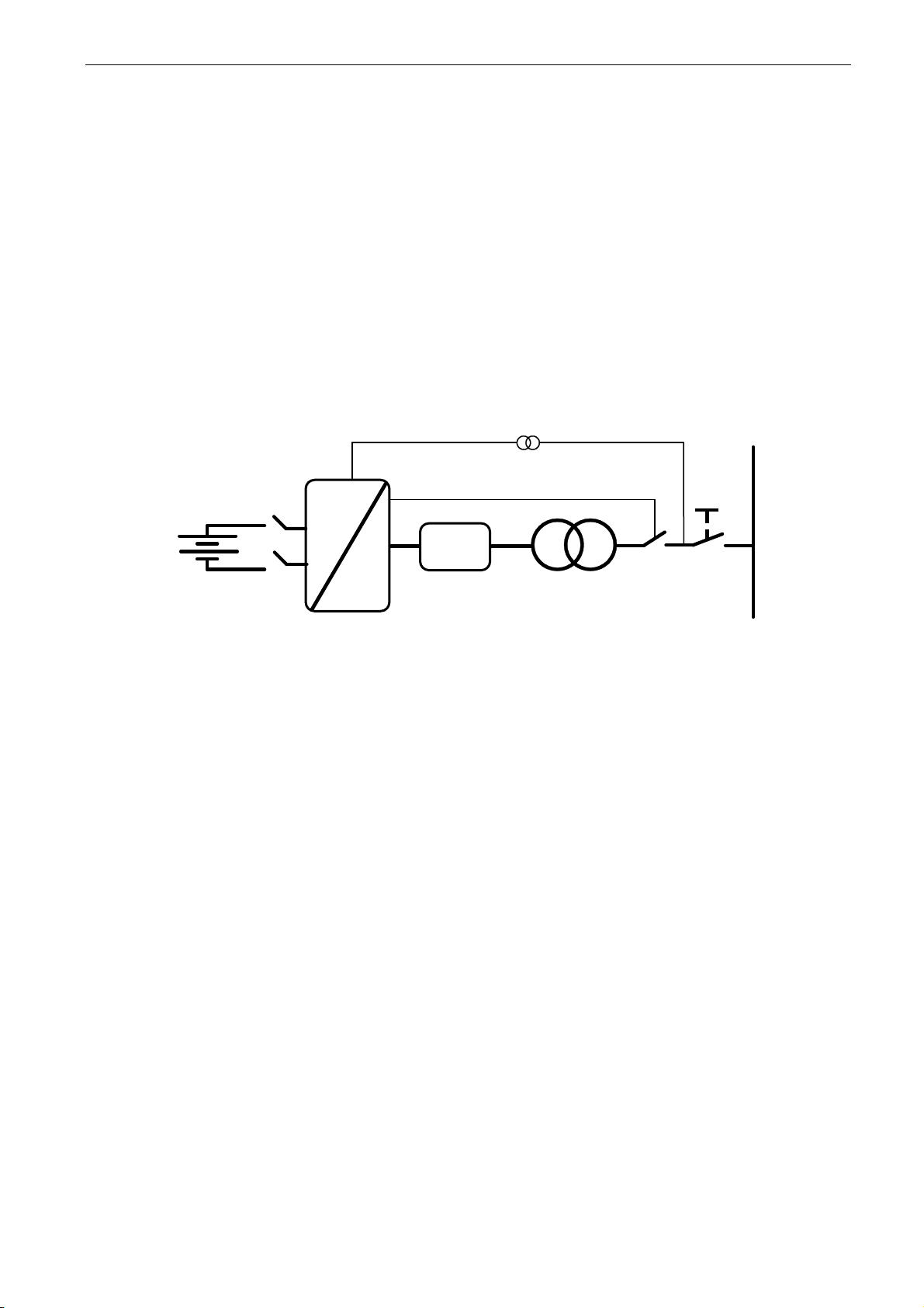
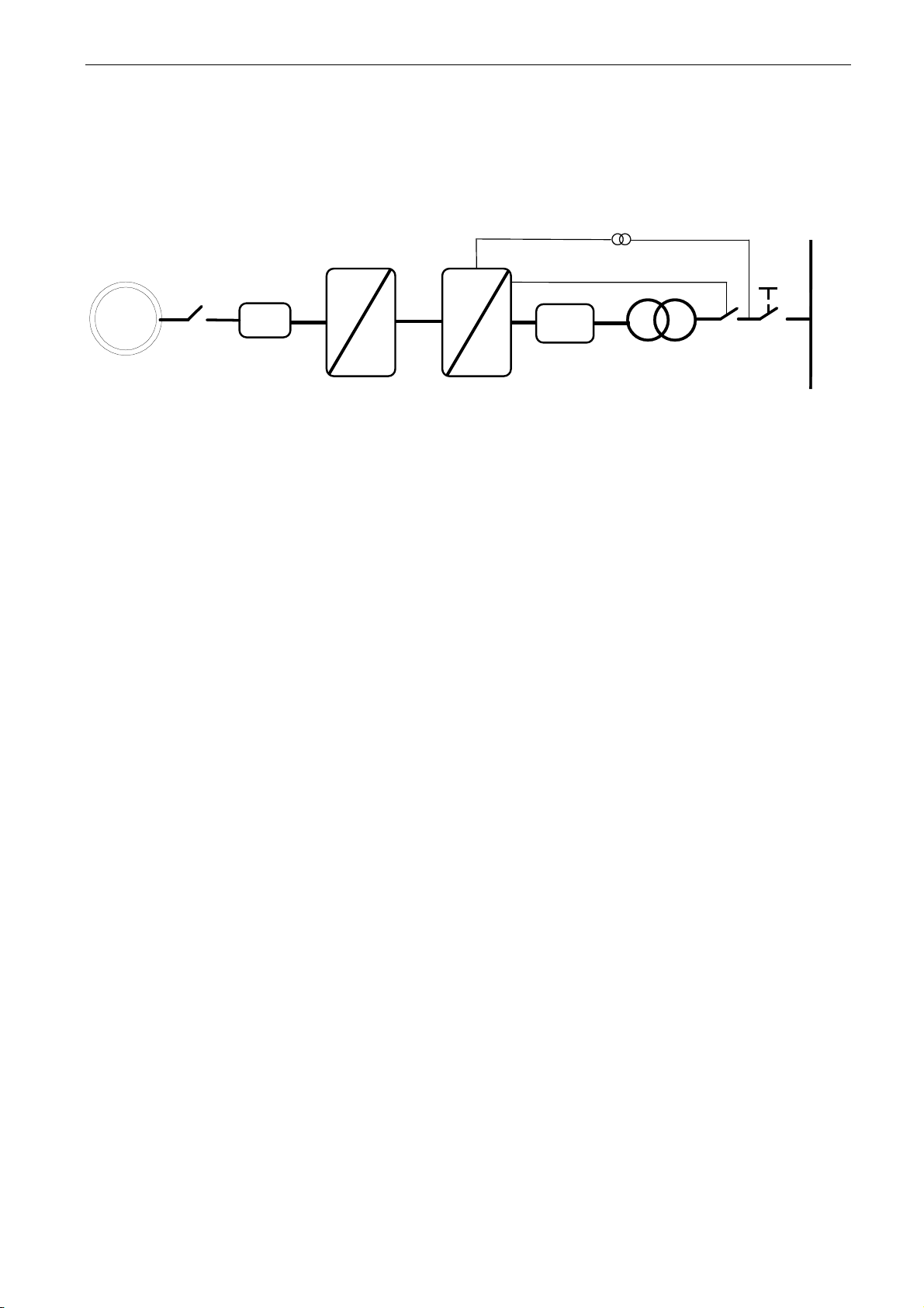
1.1 AFE Control
AFE function keeps constant DC voltage. AFE mode transfers power between DC and AC. AFE
cannot create grid by itself, it needs to be connected to existing grid.
Utility Grid
T1
Q1
U4
U3
U5
=
~
Filter
U4 = Transf. GC Side
U5 = Transf. Grid Side
D7
S1
D Y
T2
MCB Control
Figure 1.
Page 10
10 · VACON® arfif106 Grid Converter + Grid Codes
Local contacts: http://drives.danfoss.com/danfoss-drives/local-contacts/
Classified as Public
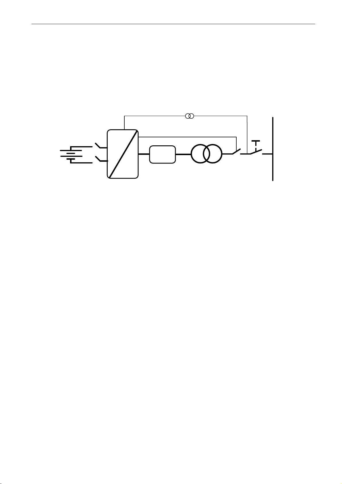
1.2 Island (Static Power Supply)
Island mode generates constant voltage and frequency. In island mode DC Voltage is not controlled.
Island mode cannot operate in parallel with other power sources in AC side, because the drive will
not balance reactive or active power with other power sources.
DC voltage level needs to be considered to have correct voltage on AC side in different load
situations, considering voltage losses in LCL filter and in transformer.
Utility Grid
T1
Q1
U4
U3
U5
=
~
Filter
U4 = Transf. GC Side
U5 = Transf. Grid Side
D7
S1
D Y
T2
MCB Control
Figure 2.
Page 11
arfif106 Grid Converter + Grid Codes VACON® · 11
Local contacts: http://drives.danfoss.com/danfoss-drives/local-contacts/
Classified as Public
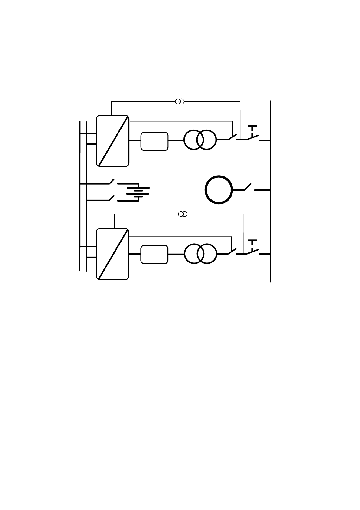
1.3 Micro Grid
Micro Grid mode controls the grid voltage and frequency. It functions like an ordinary generator.
Micro Grid mode does not control DC Voltage.
With the help of voltage droop and frequency droop, more than one Micro Grid and/or Generators
can work together.
Q1
Utility Grid
=
~
Filter
U4 = Transf. GC Side
U5 = Transf. Grid Side
T1
S1
Q1
U4
U3
U5
=
~
Filter
U4 = Transf. GC Side
U5 = Transf. Grid Side
D7
S1
G1
Q2
U4
U5
U3
T1
D7
D Y
T2
D Y
T2
MCB Control
MCB Control
Figure 3.
Page 12

12 · VACON® arfif106 Grid Converter + Grid Codes
Local contacts: http://drives.danfoss.com/danfoss-drives/local-contacts/
Classified as Public
1.4 Acronyms
AC = Alternating Current
AI = Analogue Input
AIO
=
All-In-One Applications
AM = Asynchronous Motor
ASIC
=
Application Specific Integrated Circuit
CL = Closed Loop
DC = Direct Current
DI = Digital Input
DO = Digital Output
DS = DriveSynch
FB = Field Bus
FFT
=
Function To Terminal
FW = Firmware
FWP
=
Field Weakening Point
FWPV
=
Field Weakening Point Voltage
GE = Greater or Egual
HW = Hardware
I/f
=
Current / Frequency
Id = Magnetization Current
IGBT
=
Insulated Gate Bipolar Transistor
INV
=
Inversion
Iq = Torque Producing Current
k-factor
=
Reactive relation to voltage. k = (Δiq/In)/(ΔU/Un)
LT = Less Than
MF = Master-Follower
OL = Open Loop
OV = Over Voltage
PID
=
Proportional Integral Derivative
PM = Permanent Magnet
PMS
=
Power Management System
PMSM
=
Permanent Magnet Synchronous Motor
PU = Per Unit
RO = Relay Output
RS = Reset Set
SB = System Bus
Sep.Ex SM
=
Separately Excitated Synchronous Motor
SM = Synchronous Machine
SPC
=
Speed Control
SQS
=
Safe Quick Stop
SR = Set Reset
SRM
=
Synchronous Reluctance Motor
SS1
=
Safe Stop 1
STO
=
Safe Torque Off
SW = Software
TC = Torque Control
TC = Time Constant
TTF
=
Terminal To Function
U/f
=
Voltage / Frequency
UV = Under Voltage
Page 13

arfif106 Grid Converter + Grid Codes VACON® · 13
Local contacts: http://drives.danfoss.com/danfoss-drives/local-contacts/
Classified as Public
1.5 Compatibility issues in parameters between versions
Update Note 1: This application parameters are not kept backwards compatible if new features or
improvements would be difficult to implement by doing so. Read this change note and chapter
“Compatibility issues in parameters between versions” from manual before updating the application.
Update Note 2: It’s recommended to use compare function for parameter changes when updating
application, especially in cases when version number change is considerably high.
Application is constantly developed; this includes changing parameter default values, and if
parameters are directly downloaded to drive improved default values may be lost.
V122
Page 14
14 · VACON® arfif106 Grid Converter + Grid Codes
Local contacts: http://drives.danfoss.com/danfoss-drives/local-contacts/
Classified as Public
2. Grid Codes
In AFE mode Grid Codes are available (Island mode and uGrid mode do not support Grid Codes).
To use Grid Codes, OPT-D7 is needed along with P2.17.1 Grid Code license.
Grid Codes are enabled with P2.17.3 EnableGridCode selection 2 / Enabled, whole parameter group
G2.17 is dedicated for grid code settings, by default, no grid code functionalises area active other
than unspecific frequency and voltage level tripping limits.
NOTE! Drive Grid Codes are compliant only when drive itself is controlling the MCB.
In case of upper system is controlling the breaker, the upper system will need certification.
Utility Grid
T1
Q1
U4
U3
U5
=
~
Filter
U4 = Transf. GC Side
U5 = Transf. Grid Side
D7
S1
D Y
T2
MCB Control
Page 15
arfif106 Grid Converter + Grid Codes VACON® · 15
Local contacts: http://drives.danfoss.com/danfoss-drives/local-contacts/
Classified as Public
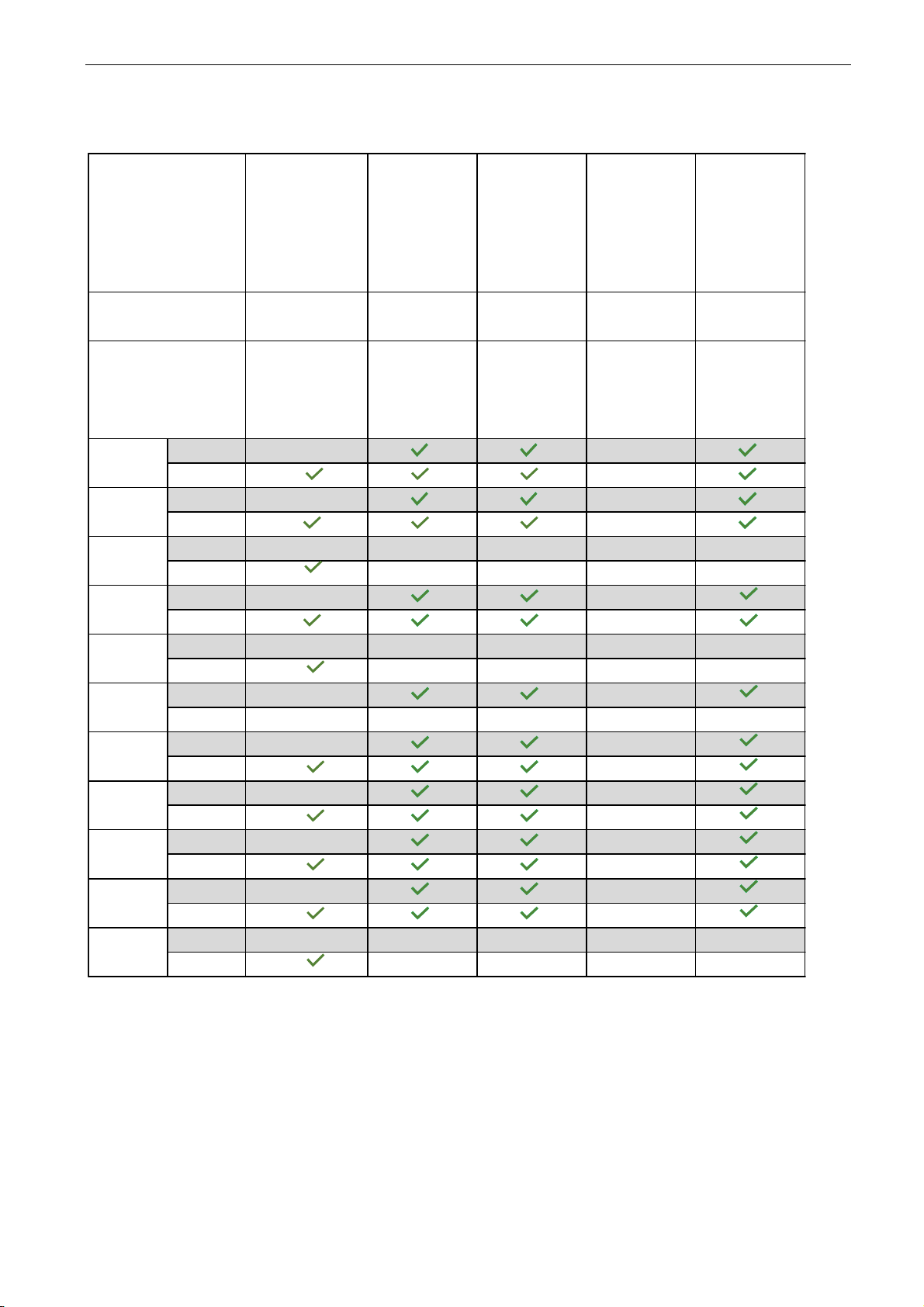
2.1 Grid Codes compliance
UL1741,
UL1741SA,
IEEE1547:2003,
IEEE1547.1:2005;
California Rule21,
Hawaii 14H
(USA/Canada)
ENTSO-e
Regulation
2016/031 of 14 of
April 2016
(Europe)
IEC62116:2014
(Anti-islanding)
(International)
EN50549-1:2019
EN50549-2:2019
(estimated April
2021)
(Europe)
VDE-AR-N-4105,
VDE-AR-N-
4110,
VDE-AR-N-4120
(Germany)
NXP2V200
NXP2V203
or later
NXP2V203
or later
NXP2V203
or later
NXP2V203
or later
ARFIF106 V103
ARFIF106
V121 or later
release
ARFIF106
V121 or later
release
ARFIF106
V121 or later
release
ARFIF106
V121 or later
release
400VAC
600VAC
400VAC
600VAC
400VAC
600VAC
400VAC
600VAC
400VAC
600VAC
400VAC
600VAC
400VAC
600VAC
400VAC
600VAC
400VAC
600VAC
400VAC
600VAC
400VAC
600VAC
CH63
CH64
2xCH64
FI12
FI13
FI14
CH5
CH61
CH62
Electric connection Grid
codes and Electrical
Safety standards
System software
Application software
FI9
FI10
Page 16
16 · VACON® arfif106 Grid Converter + Grid Codes
Local contacts: http://drives.danfoss.com/danfoss-drives/local-contacts/
Classified as Public
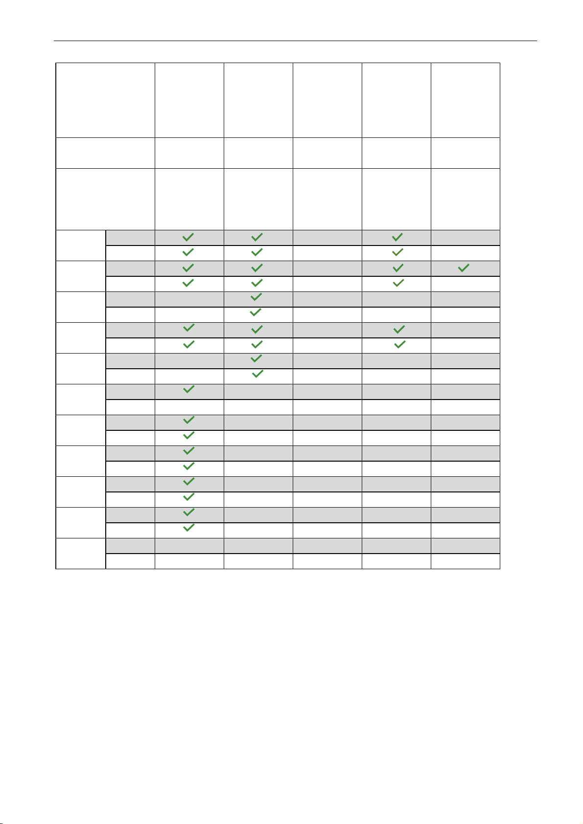
FGW TG3 rev
24,
FGW TG4 rev 8,
FGW TG8 rev 7
(Germany /
BDEW)
CEI 0-16: 04-
2019,
CEI 0-21: 04-
2019
(Italy)
Regulation
2016/631 of 14 of
April 2016;
(France)
IEC62109-1;
IEC62109-2;
AS/NZS
4777.2:2015
(PV)(Australia)
PEA (Thailand)
NXP2V203
or later
NXP2V203
or later
NXP2V203
or later
NXP2V200
or later
NXP2V203
or later
ARFIF106
V121 or later
release
ARFIF106
V121 or later
release
ARFIF106
V121 or later
release
ARFIF106
V104 or V121
or later release
ARFIF106
V121 or later
release
400VAC
600VAC
400VAC
600VAC
400VAC
600VAC
400VAC
600VAC
400VAC
600VAC
400VAC
600VAC
400VAC
600VAC
400VAC
600VAC
400VAC
600VAC
400VAC
600VAC
400VAC
600VAC
FI13
FI14
CH5
CH63
CH64
2xCH64
CH61
CH62
Electric connection Grid
codes and Electrical
Safety standards
System software
Application software
FI9
FI10
FI12
Page 17

arfif106 Grid Converter + Grid Codes VACON® · 17
Local contacts: http://drives.danfoss.com/danfoss-drives/local-contacts/
Classified as Public
3. Quick start and operation principles
NOTE! Before you start the commissioning, read the safety instructions in the user manual of your
product.
To use the Island, Micro Grid, or Shaft generator operation, you need a licence key. The AFE mode
is available without a licence.
This application requires an NXP3 control board VB761 or newer.
The control place (P3.1) of the Grid Converter drive is Keypad as a default.
The basic I/O configuration of the Grid Converter drive consists of OPT-A1, OPT-A2, and OPT-D7
option boards. The basic I/O configuration is described in Table 1.
OPT-D7 is required when the Grid Converter unit is needed to start with zero power to the grid. If
grid frequency is not monitored with OPT-D7, the unit may go generator side or directly to full power
because different reference frequency and grid frequency.
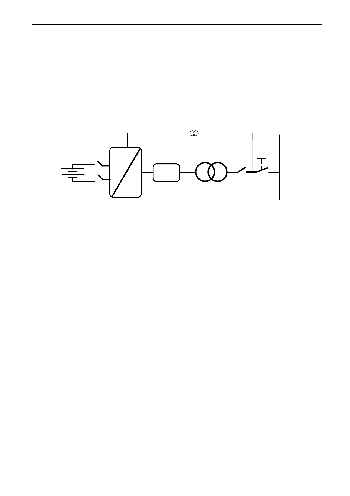
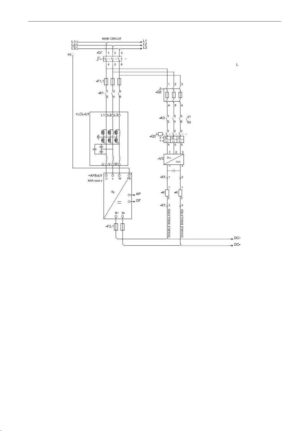
The Grid Converter is utilised by using AFE hardware with special software. An external LC(L)-filter
and charging circuit is needed. This unit is selected when low harmonics are required. The principle
connection of AFE drive has been described in Figure 4.
The external 24 Vdc is recommended for control board(s). It enables the setting of parameters even
when the power unit itself is not powered. This is important also when software updates are made.
Some default I/O configuration of the application can cause unexpected DO operation. When the
control board is powered, the drive can give information from the status of the system if, for example,
the drive I/O is used for an overall system monitoring.
The external 24 Vdc is required for the drives in cases where the start command starts the control
board-controlled precharging operation.
3.1 Quick start instructions
1. Connect the unit according to the Figure 4.
2. Power up the control unit with 24 Vdc.
3. Set the basic parameters (G2.1)
4. Check that the digital input parameters (G2.4.2) have been set according to the connections.
5. Change the control place according to the system requirements.
6. Charge the unit.
3.2 In case of parallel AFE:
1. Set P2.1.5 Parallel AFE to Yes. This will also set DC Drooping to 3.00% (Default).
Page 18
18 · VACON® arfif106 Grid Converter + Grid Codes
Local contacts: http://drives.danfoss.com/danfoss-drives/local-contacts/
Classified as Public
Figure 4. Connection
Page 19

arfif106 Grid Converter + Grid Codes VACON® · 19
Local contacts: http://drives.danfoss.com/danfoss-drives/local-contacts/
Classified as Public
3.3 Pre-Charging of DC
This AFE application has its own charging control, P2.5.1.13 DC Charge (24 Vdc required for control
board) and charging protection in case the external charging cannot get DC voltage to required level
within set time P2.9.1.6 Charge Max Time (provided that the DC Voltage reaches the under voltage
fault level).
The charging function is activated when P2.5.1.13 DC Charge is A.1 or higher. When the control
place is IO, Keypad or NCDrive, charging is started from the start command.
Charging is not started if:
- Drive is in fault state.
- P2.4.2.26 Enable CB Close is FALSE
- P2.4.2.8 Run Enable is FALSE
- P2.4.2.19 Quick Stop is FALSE
Charging is also stopped if above conditions occur during charging or if the start command is
removed.
For fieldbus control, charging is started with B0 of FB Control Word on the supporting FB profiles.
Charging is also stopped if B0 goes low. Also MCB is opened if already closed.
DC Charge (F80) is given if 85 % of DC Nominal is not reached within P2.9.1.6 Charge Max Time
and charging is stopped.
DC Charging is stopped when the drive receives feedback from P2.4.2.4 MCB Feedback.
NOTE! Use suitably sized DC Charging resistor. To select the correct size, check Pulse loadability
for time duration set in for Max Charge Time parameter.
Page 20

20 · VACON® arfif106 Grid Converter + Grid Codes
Local contacts: http://drives.danfoss.com/danfoss-drives/local-contacts/
Classified as Public
3.4 Main circuit breaker control (MCB)
The Grid Converter application controls the circuit breaker of the system with the relay output RO2.
When the DC bus is charged, the MCB will be closed. The status of the MCB is monitored via a
digital input. The digital input used for monitoring is selected with parameter P2.3.1.3. Faults can be
set to open the MCB by selecting a response to a fault to be 3=Fault, DC OFF.
An external charging circuit is necessary to charge the DC bus but drive can control this circuit if 24
Vdc is provided for the control board.
Closing limit is 85% of the nominal DC Voltage.
Opening limit is 75% of the nominal DC Voltage.
Nominal DC Voltage for the Grid Converter is adjusted with System Nominal DC parameter P2.1.7
ID1805.
Over Current (F1), Hardware IGBT (F31) and Software IGBT (F41) faults will open MCB immediately
to protect the drive.
For Grid Code use its recommended to have breaker that mechanical opening delay is less than 30
ms when clearing times are less than 200 ms also use early brake auxiliary contact as accessory to
breaker of contact.
NOTE! Drive Grid Codes are compliant only when drive itself is controlling the MCB.
NOTE! The MCB feedback is necessary for the correct operation of the Grid Converter application.
NOTE! Only the drive controls its own MCB. If additional interlocks or opening commands are
needed, these commands must go through the drive.
NOTE! UPS may be needed during short circuit situation to keep MCB closed if control voltage is
taken from the grid where the short circuit occurs.
NOTE! Missing feedback signal prevent drive going to ready state. MCB Feedback can be monitored
from Status Word B10.
NOTE! If feedback is not used there will be three second forced delay on internally generated MCB
feedback signal. MCB Feedback can be monitored from Status Word B10.
Page 21
arfif106 Grid Converter + Grid Codes VACON® · 21
Local contacts: http://drives.danfoss.com/danfoss-drives/local-contacts/
Classified as Public
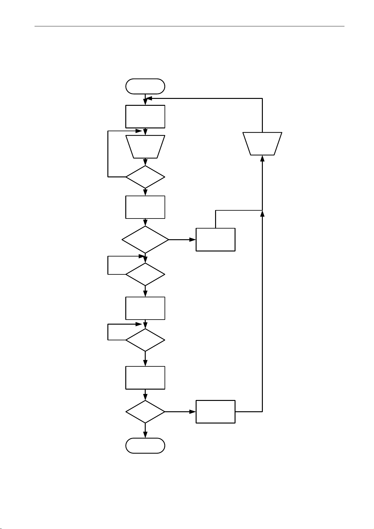
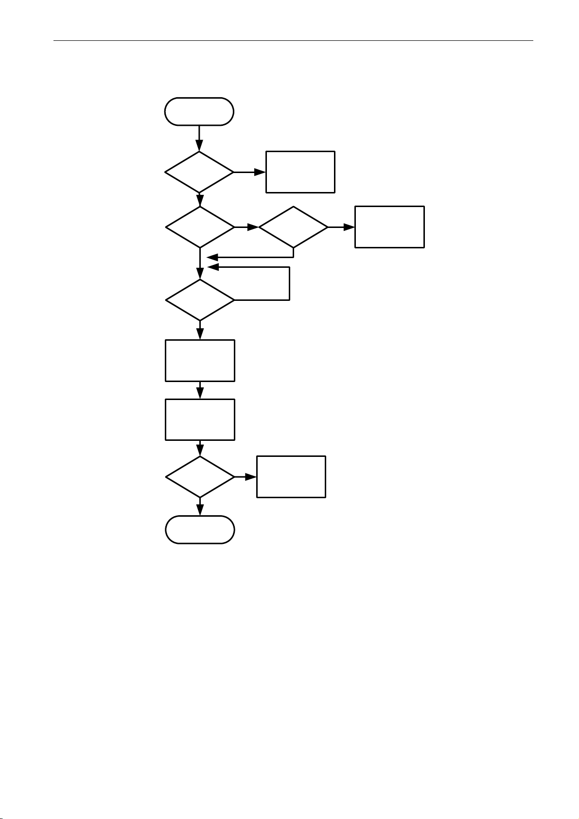
3.5 Start Sequence
In uGrid mode synchronization to main is done also but if grid is not found drive will make the grid. In
Island mode drive will make the grid immediately without synchronization to the grid.
Ready to switch on
Charge DC-
Link
DC-Link
> 85 %
NO
Close Main
Contactor
YES
Main Contactor
Closed
YES
NO
MCC Fault
Fault Rese t
Run Enable
Ready To Run
NO
Start Signal
YES
NO
Synchronize with
mains
Synch O K
NO
YES
Line Synch Fault
F10
Running
Start
Figure 5. AFE start sequence
Page 22
22 · VACON® arfif106 Grid Converter + Grid Codes
Local contacts: http://drives.danfoss.com/danfoss-drives/local-contacts/
Classified as Public
3.6 Stop sequence
Modulating
MCB Closed
No
F64 A4
Open MCB
No
Yes
Yes
Stop Modulation
(If Run State)
Open MCB
Stop Request MCB Closed
No
F64 A2
(If DC > 85 %)
(Delayed)
Yes
MCB Closed
No
Yes
F64 A3
(Delayed)
End
Figure 6. Stop sequence
Page 23
arfif106 Grid Converter + Grid Codes VACON® · 23
Local contacts: http://drives.danfoss.com/danfoss-drives/local-contacts/
Classified as Public
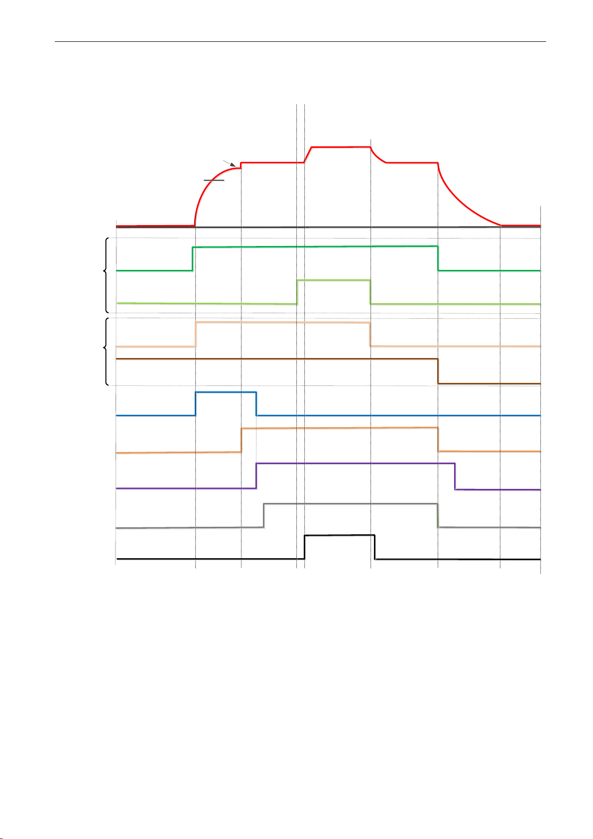
3.7 Start Stop timing diagram
DC Voltage
Charge Control
MCB Feedback
MCB Close Control
MCB Close level
Stable DC
Ready
IO Start
Run
FB CW.B00
Control in
FB Control
FB CW.B03
Contro in
IO Control
P. Start Delay
IO MCB Open
Command
Above example when “Standard” state machine is used. With “Basic” state machine operation
is like in IO Control.
Page 24
24 · VACON® arfif106 Grid Converter + Grid Codes
Local contacts: http://drives.danfoss.com/danfoss-drives/local-contacts/
Classified as Public
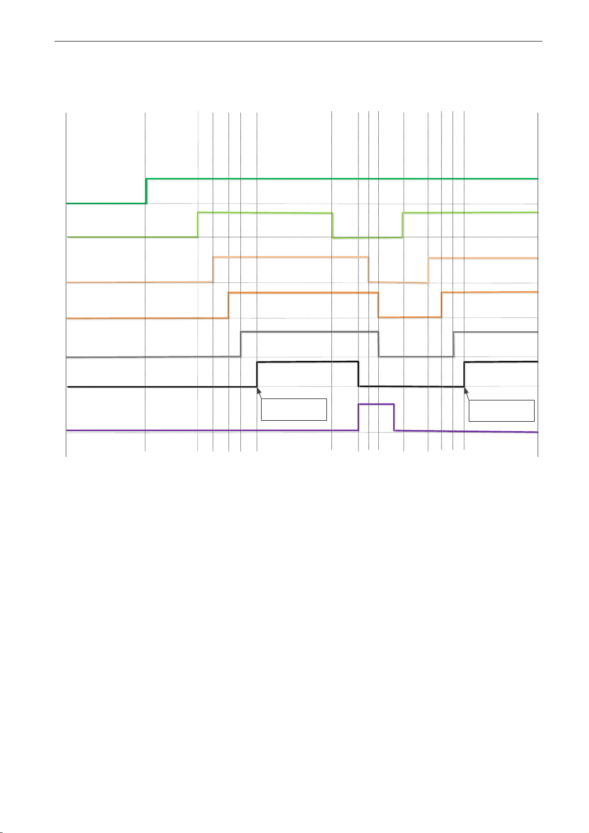
3.8 Start Stop Timing Diagram with Grid Codes
Main Circuit Breaker
Feedback
Main Circuit Breaker
Close Control
Ready State of
Inverter
Start Request
To Inverter
Run
(Modulating)
Line Frequency
and Voltage OK
P. Line OK Delay
P. Start Delay
Grid Code Trip
P. ReConnect
Time
Start
Synchronization
Start
Synchronization
Page 25
arfif106 Grid Converter + Grid Codes VACON® · 25
Local contacts: http://drives.danfoss.com/danfoss-drives/local-contacts/
Classified as Public
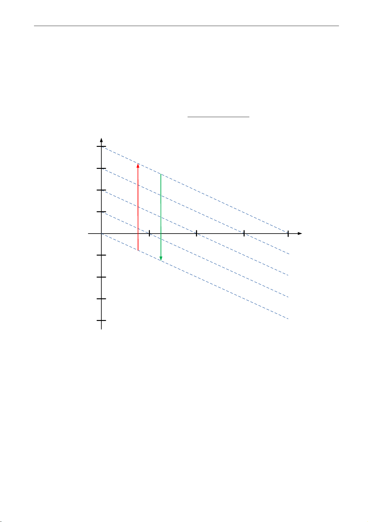
3.9 Operation principle: Droop Speed Control Mode
When the power demand increases, all generators on the grid allow frequency to droop. This will
balance the load between all the generators on the grid. Then the power management system gives
all generators a command to increase frequency so that the grid frequency is maintained at its
nominal value.
When the load is reducing on the grid, the frequency of the generators will increase, and the power
management system gives a command to decrease frequency.
+1%
+2%
+3%
+4%
-1%
-2%
-3%
-4%
50,5 Hz
51,0 Hz
51,5 Hz
52,0 Hz
48,0 Hz
48,5 Hz
49,0 Hz
49,5 Hz
50,0 Hz
Loading
Un-loading
Drooping
Freq. Change
25% 50% 75% 100%
Related
Load
Figure 7.
3.10 Operation principle: Isochronous Control Mode
In the isochronous control mode, the Micro Grid frequency reference is kept the same as the grid
frequency with help of OPT-D7. This will keep power at zero regardless of grid frequency. While
drive operates in drooping mode, the actual power is controlled by base current reference. This
reference needs to be controller by power management system (PMS) that will handle power sharing
between different machines on the grid.
Page 26
26 · VACON® arfif106 Grid Converter + Grid Codes
Local contacts: http://drives.danfoss.com/danfoss-drives/local-contacts/
Classified as Public
3.11 Voltage compensation
Grid Converter system will have voltage losses. Depending on the system, the losses may be more
than 50 Vac when operating close to Grid Converter nominal currents with low power factor between
points U3 and U5. This voltage loss needs to be compensated so that the grid voltage stays at
nominal. This also sets requirements for the needed DC link voltage.
Q1
T2
U4
U3
U5
UDCU2
=
~
=
~
Filter
Filter
SG
U1
Q2
U4 = Transf. GC Side
U5 = Transf. Grid Side
D7
T1
S1
MCB Control
Utility Grid
50 Hz
60 Hz
Figure 8. Voltage compensation
The normal operation voltage range in a land-based grid is usually between 80% and 115% of the
grid nominal voltage.
The voltage losses compensation is handled separately for Active power (kW) and Reactive power
(kVar), the latter being more significant. The Active power voltage losses are compensated with
Inductor Losses parameter (P2.2.6.6) and Reactive power voltage losses are compensated with
Inductor Size parameter (P2.2.6.5).
Uncompensated system may result in unnecessary reactive power circulation in a grid between the
different power sources and wrong grid voltage.
OPT-D7 can be used to compensate the voltage losses (closed loop voltage compensation) but it is
recommended to do an open loop voltage compensation tuning in case of OPT-D7 failure. When the
OPT-D7 measurements exceed the set limit values, the voltage compensation falls back to open
loop control.
Inductor Size and Losses affect
Grid Nom. Voltage: 400 Vac, Reactive Current: 30%, Active Current 50%, Inductor
Size: 15%, Inductor Losses: 15%, Voltage Correction: 0 Vac.
Reactive Increase: 400 Vac×30%×15%=18 Vac
Active Increase: 400 Vac Increase or Losses: 15% 400 Vac×50%×15%×15%=4.5 Vac
Total increase: 18 Vac+4.5 Vac =22.5 Vac
See also chapter 10.1 Open Loop Voltage Compensation.
Page 27

arfif106 Grid Converter + Grid Codes VACON® · 27
Local contacts: http://drives.danfoss.com/danfoss-drives/local-contacts/
Classified as Public
3.12 OPT-D7 voltage measurement option board
OPTD7 is an AC sinusoidal voltage measurement board. Using this board, the drive measures the
line voltage, the frequency and the voltage angle information.
Grid Codes cannot be used or activated without correctly connected OPT-D7 board and Grid Code
functionality is only available when drive is operating in AFE mode.
Measurement accuracies of OPT-D7 board
Frequency Accuracy: ±0,05 Hz
Voltage Accuracy: ±2,5% from full range.
The drive can compare this information with its output voltage angle when it runs. This feature can
be used to make synchronisations to a grid that is measured. For example, for line synchronisation
purposes you can use APFIFF44 LineSynch II Application. That will work as a smooth starter.
In Grid Converter application this can be used:
- To synchronise to existing external grid while the drive is running to enable bumpless transfer
from a generator operation to a shore powered operation in a ship.
- To control the grid voltage (Voltage losses compensation).
- To enable a zero power connection to an existing grid.
- To help in the commissioning of drive active power and reactive power voltage losses
compensation when the actual grid voltage is visible in NCDrive.
The OPT-D7 board is delivered with a measurement transformer (690 :11,5) which is suitable for a
voltage range up to 690 Vac. The measurement transformer cannot be connected directly to drive
output terminal since it can’t measure pulse width modulated (PWM) voltage input.
It is possible to use a customised transformer when the input voltage to be measured is not within
the OPT-D7 transformer voltage range. The transformation ratio parameter can be adjusted
according to the transformer primary to secondary ratio. See details in the OPT-D7 user manual.
Synchronisation to the grid can be made without the OPT-D7 when the drive operates in the AFE or
the Micro Grid mode. This requires that the output terminals of the drive are connected to the
existing grid when the drive is in the STOP state. When a start command has been given in AFE or
Micro Grid mode, the drive will make standard AFE synchronisation. Depending on the operation
mode, the drive will start to keep constant DC voltage (AFE) or start to share power based on grid
frequency (Micro Grid). Using OPT-D7 for synchronisation will make the start of the drive smoother.
If the drive does not detect an existing line voltage or frequency in Micro Grid mode, the output
voltage is raised defined time (VoltageRiseTime). In the Island mode, the detection of the grid is not
made and the voltage is raised from zero in the set time (VoltageRiseTime).
NOTE: The OPT-D7 board (in slot C) is mandatory for the Grid Converter unit.
Page 28

28 · VACON® arfif106 Grid Converter + Grid Codes
Local contacts: http://drives.danfoss.com/danfoss-drives/local-contacts/
Classified as Public
-
Page 29
arfif106 Grid Converter + Grid Codes VACON® · 29
Local contacts: http://drives.danfoss.com/danfoss-drives/local-contacts/
Classified as Public
4. Control I/O
4.1 Slot A and Slot B terminals
Table 1. Minimum recommended I/O configuration.
OPT-A1
Terminal
Signal
Description
1
+10V
ref
Reference voltage output
Voltage for potentiometer, etc.
2
AI1+
Analogue input 1.
Range 0-10V, Ri = 200
Range 0-20 mA Ri = 250
Input range selected by jumpers.
Default range: Voltage 0 – 10 V
3
AI1-
I/O Ground
Ground for reference and controls
4
AI2+
Analogue input 2.
Range 0-10V, Ri = 200
Range 0-20 mA Ri = 250
Input range selected by jumpers.
Default range: Current 0 – 20 mA
5
AI2-
6
+24V
Control voltage output
Voltage for switches, etc. max 0.1 A
7
GND
I/O ground
Ground for reference and controls
8
DIN1
Programmable G2.2.1
9
DIN2
Programmable G2.2.1
10
DIN3
Programmable G2.2.1
11
CMA
Common for DIN 1– DIN 3
Connect to GND or +24V
12
+24V
Control voltage output
Voltage for switches (see #6)
13
GND
I/O ground
Ground for reference and controls
14
DIN4
MCB Feedback
Programmable G2.2.1
0 = MCB open
1 = MCB closed
15
DIN5
Quick Stop
Programmable G2.2.1
0 = Quick Stop Active
1 = No Quick Stop
16
DIN6
Programmable G2.2.1
17
CMB
Common for DIN4– DIN6
Connect to GND or +24V
18
AO1+
Analogue output 1
Programmable
Range 0– 20 mA/RL, max. 500
19
AO1-
20
DO1
Digital output
READY
Programmable P2.3.1.1
Open collector, I50mA, U48 VDC
OPT-A2
21
RO1
Relay output 1
Programmable P2.3.1.2
Switching capacity
24 VDC / 8 A
22
RO1
23
RO1
250 VAC / 8A
125 VDC / 0.4 A
24
RO2
Relay output 2
MCB control
This RO is not programmable.
Fixed for MCB Control (Close)
25
RO2
26
RO2
4.2 Terminal To Function (TTF)
The programming principle of the input and output signals in the Grid Converter Application is
different compared to the conventional method used in other VACON® NX applications.
In the conventional programming method, Function to Terminal Programming Method (FTT), you
have a fixed input or output that you define a certain function for. The applications mentioned above,
however, use the Terminal to Function Programming method (TTF) in which the programming
pro¬cess is carried out the other way round: Functions appear as parameters which the operator
defines a certain input/output for.
Page 30
30 · VACON® arfif106 Grid Converter + Grid Codes
Local contacts: http://drives.danfoss.com/danfoss-drives/local-contacts/
Classified as Public
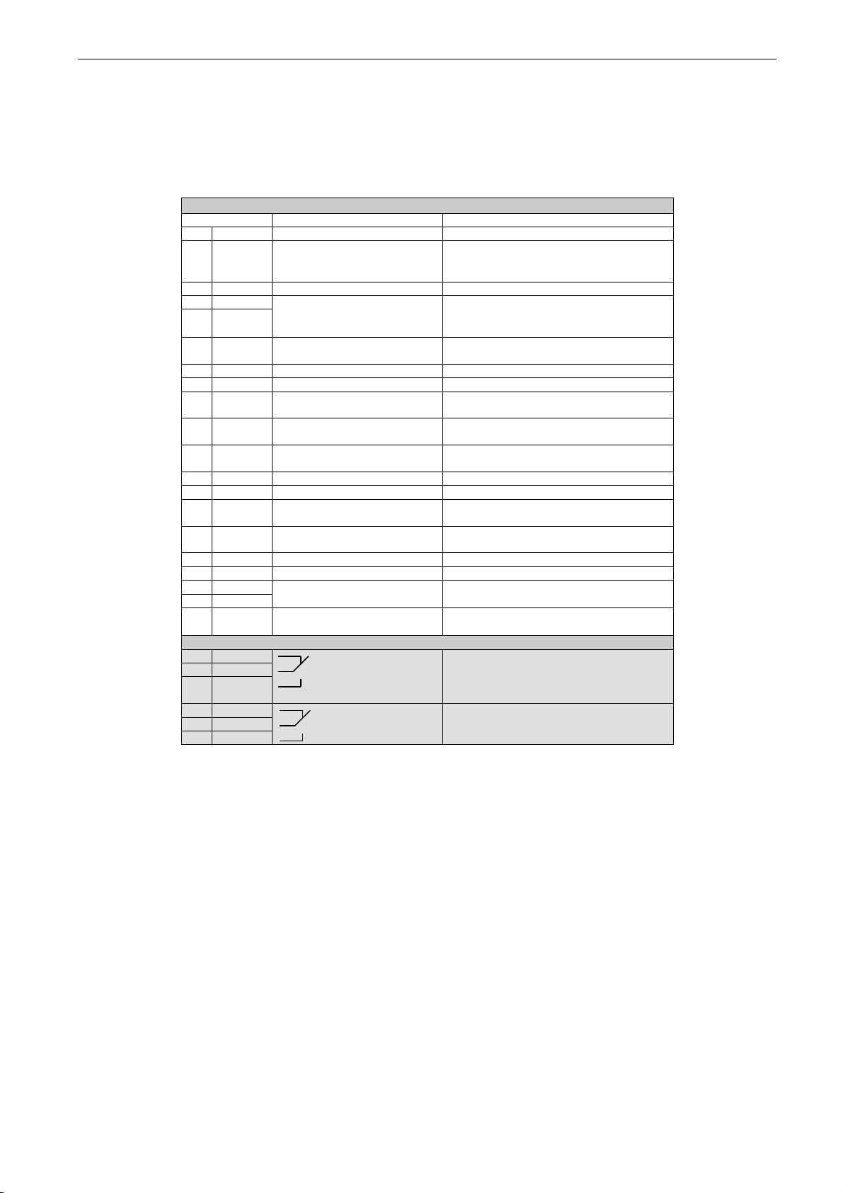
4.1 Defining inputs and outputs
Connecting a certain input or output with a certain function (parameter) is done by giving the
parameter an appropriate value. The value is formed of the Board slot on the VACON® NX control
board (see VACON® NX User Manual) and the respective signal number, see below.
Function name
Slot Terminal number
Terminal type
Example: You want to connect the digital output function Reference fault/warning (parameter
2.3.3.7) to the digital output DO1 on the basic board NXOPTA1 (see VACON® NX User Manual).
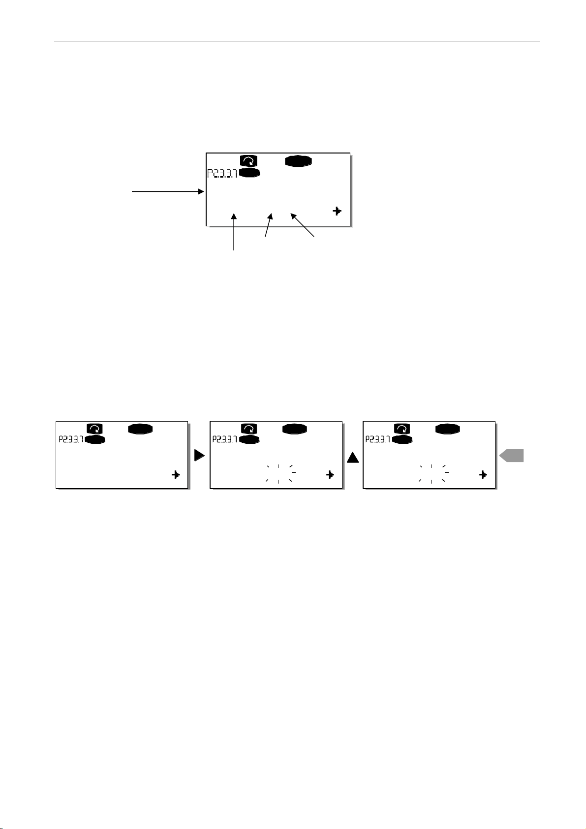
First find the parameter 2.3.3.7 on the keypad. Press the Menu button right once to enter the edit
mode. On the value line, you will see the terminal type on the left (DigIN, DigOUT, An.IN, An.OUT)
and on the right, the present input/output the function is connected to (B.3, A.2 etc.), or if not
connected, a value (0.#).
When the value is blinking, hold down the Browser button up or down to find the desired board slot
and signal number. The program will scroll the board slots starting from 0 and proceeding from A to
E and the I/O selection from 1 to 10.
Once you have set the desired value, press the Enter button once to confirm the change.
READY
I/Oterm
DigOUT:B.1
AI Ref Faul/Warn
READY
I/Oterm
DigOUT:0.0
READY
I/Oterm
DigOUT:0.0
READY
I/Oterm
DigOUT:B.1
enter
AI Ref Faul/Warn AI Ref Faul/Warn AI Ref Faul/Warn
Page 31

arfif106 Grid Converter + Grid Codes VACON® · 31
Local contacts: http://drives.danfoss.com/danfoss-drives/local-contacts/
Classified as Public
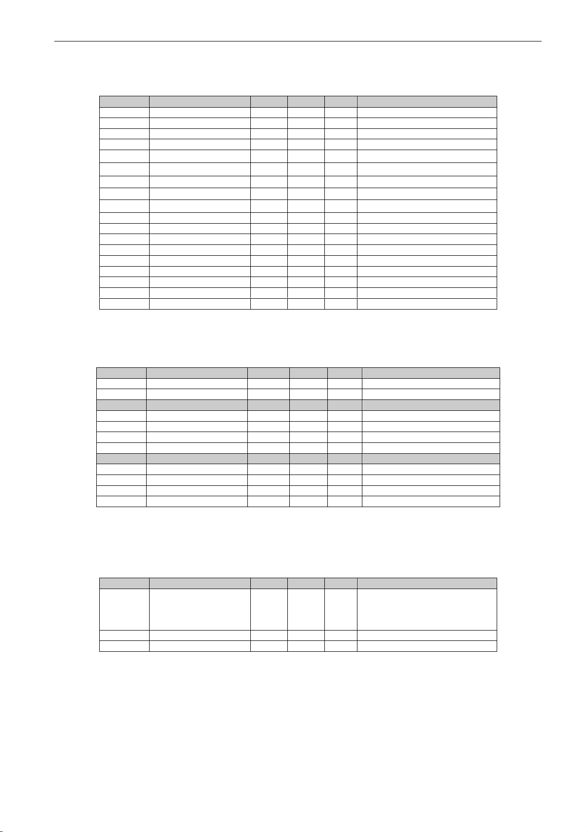
4.1 Defining a terminal in NCDrive
If you use the VACON® NCDrive Programming Tool for parametrizing you will have to establish the
connec¬tion between the function and input/output in the same way as with the control panel. Just
pick the address code from the drop-down menu in the Value column (see the Figure below).
Figure 3 1. Screenshot of NCDrive programming tool; Entering the address code
Be ABSOLUTELY sure not to connect two functions to one and
same output in order to avoid function overruns and to ensure
flawless operation.
!
WARNING
Note: The inputs, unlike the outputs, cannot be changed in RUN state.
Page 32

32 · VACON® arfif106 Grid Converter + Grid Codes
Local contacts: http://drives.danfoss.com/danfoss-drives/local-contacts/
Classified as Public
5. Monitoring signals
The menu M1 (Monitoring) has all the monitoring values.
Column explanations:
Code = Location indication on the keypad; Shows the operator the present parameter
number
Parameter = Name of parameter
Min = Minimum value of parameter
Max = Maximum value of parameter
Unit = Unit of parameter value; Given if available
Default = Value preset by factory
Cust = Customer’s own setting
ID = ID number of the parameter
_____ = On parameter code: Parameter value can only be changed after the FC has been
stopped.
_____ = Apply the Terminal to Function method (TTF) to these parameters (see chapter
Error! Reference source not found.)
_____ = Monitoring value is possible to control from fieldbus by ID number
The manual presents signals that are not normally visible for monitoring. i.e. is not a parameter or
standard monitoring signal. These signals are presented with [Letter]. e.g.
[FW]MotorRegulatorStatus
[V] Normal monitoring signal
[P] Normal parameter in application.
[FW] Firmware signal, Can be monitored with VACON® NCDrive when signal type is selected
Firmware
[A] Application signal, can be monitored with VACON® NCDrive when signal type is selected
Application.
[R] Reference type parameter on keypad.
[F] Function. Signal is received as a output of function.
[DI] Digital input signal.
5.1 Monitoring value tables
5.1.1 Monitoring values 1
Code
Parameter
Unit
Form.
ID
Description
V1.1.1
DC-Link Voltage
V # 1108
Measured DC Link voltage in volts,
filtered.
V1.1.2
DC Voltage Ref.
%
#,##
1200
Used DC voltage reference by the
regenerative unit in % of Nominal DC
voltage.
Nominal DC voltage = 1.35 * supply
voltage
V1.1.3
DC Voltage Act.
%
#,##
7
Same scaling as DC Voltage Ref.
V1.1.4
Total Current
A
Varies
1104
Filtered current
V1.1.5
Active Current
%
#,#
1125
> 0 power from AC side to DC side
< 0 power from DC side to AC side
V1.1.6
Reactive Current
%
#,#
1157
V1.1.7
Power kW
kW
Varies
1508
> 0 power from AC side to DC side
< 0 power from DC side to AC side
V1.1.8
Power %
%
#,#
5
> 0 power from AC side to DC side
Page 33

arfif106 Grid Converter + Grid Codes VACON® · 33
Local contacts: http://drives.danfoss.com/danfoss-drives/local-contacts/
Classified as Public
< 0 power from DC side to AC side
V1.1.9
Status Word
# 43 V1.1.10
Supply Frequency
Hz
#,##
1
Drive output frequency
V1.1.11
Supply Voltage
V
#,#
1107
Drive output voltage
V1.1.12
Line Frequency D7
Hz
#,##
1654
Measured line frequency
V1.1.13
Line Voltage D7
V # 1650
Measured line voltage
V1.1.14
AC Voltage
Reference
V # 1556
Used AC Voltage Reference
V1.1.15
DC Ref Max Lim
%
#,##
1606
Internal limit for DC Voltage Ref.
Page 34

34 · VACON® arfif106 Grid Converter + Grid Codes
Local contacts: http://drives.danfoss.com/danfoss-drives/local-contacts/
Classified as Public
5.1.2 Monitoring values 2
Code
Parameter
Unit
Form.
ID
Description
V1.2.1
DC Voltage
V # 44
Measured DC Link voltage in
volts, unfiltered.
V1.2.2
Operation Mode
# 1615
0 = AFE
1 = Island
2 = Micro Grid
V1.2.3
Used Current Ref
%
#,#
1704
Used current reference is
negated to parameter value.
Made to compare values in
NCDrive easier to Active current
V1.2.4
D7 Synch. Error
# 1659
Synchronisation error to external
grid
V1.2.5
Cos Phi Actual
#,###
1706 V1.2.6
Unit Temperature
°C # 1109 V1.2.7
Freq. Reference
Hz
#,#
1752
Used line frequency reference
V1.2.8
Current
A
Varies
1113
Unfiltered current
V1.2.9
Operation Hours
h
#,##
1856
V1.2.10
Reactive Current
Reference
%
#,#
1389
V1.2.11
Grid State
# 1882 V1.2.12
Mindex
%
#,#
1874
Modulation Index
V1.2.13
IU rms
A
Varies
39 V1.2.14
IV rms
A
Varies
40
V1.2.15
IW rms
A
Varies
41
V1.2.16
DC-Link Current
A
Varies
72 V1.2.17
DC-Link ActCurr
%
#,#
1158 V1.2.18
Iq Actual
%
#,#
4
Filtered by P2.17.16.11
V1.2.19
Id Actual
%
#,#
1134
5.1.3 Fieldbus monitoring values
Code
Parameter
Unit
Form.
ID
Description
V1.3.1
FB Control Word
# 1160
Control word from fieldbus
V1.3.2
FB Status Word
# 68
Status word to fieldbus
V1.3.3
Fault Word 1
# 1172
V1.3.4
Fault Word 2
# 1173 V1.3.5
Warning Word 1
# 1174 V1.3.6
FB Micro Grid CW1
# 1700
Control for Micro Grid operations
V1.3.7
FB Micro Grid SW1
# 1701
Status of Micro Grid operations
V1.3.8
Last Active Warning
# 74
V1.3.9
Last Active Fault
# 37 V1.3.10
MC Status
# 64 V1.3.11
FB Analogue Out
%
#,##
48
Page 35
arfif106 Grid Converter + Grid Codes VACON® · 35
Local contacts: http://drives.danfoss.com/danfoss-drives/local-contacts/
Classified as Public
5.1.4 I/O monitoring values
Code
Parameter
Unit
Form.
ID
Description
V1.4.1
DIN1, DIN2, DIN3
# 15 V1.4.2
DIN4, DIN5, DIN6
# 16 V1.4.3
DIN Status 1
# 56 V1.4.4
DIN Status 2
# 57
V1.4.5
Analogue Input 1
%
#,##
13 V1.4.6
Analogue Input 2
%
#,##
14
V1.4.7
Analogue input 3
%
#,##
27
AI3, unfiltered.
V1.4.8
Analogue input 4
%
#,##
28
AI4, unfiltered.
V1.4.9
Analogue Out 1
%
#,##
26
V1.4.10
Analogue Out 2
%
#,##
50
AO2
V1.4.11
Analogue Out 3
%
#,##
51
AO3
V1.4.12
PT100 Temp
°C
#,#
42
Maxim temperature
V1.4.13
PT100 Temp. 1
°C
#,#
50
V1.4.14
PT100 Temp. 2
°C
#,#
51 V1.4.15
PT100 Temp. 3
°C
#,#
52 V1.4.16
PT100 Temp. 4
°C
#,#
69 V1.4.17
PT100 Temp. 5
°C
#,#
70
V1.4.18
PT100 Temp. 6
°C
#,#
71
5.1.5 Master / Follower
Code
Parameter
Unit
Form.
ID
Description
V1.5.1
SB SystemStatus
# 1819 V1.5.2
Master CW
# 93 Code
Parameter
Unit ID
Description
V1.5.3.1
Current D1
A
Varies
1820
V1.5.3.2
Current D2
A
Varies
1821
V1.5.3.3
Current D3
A
Varies
1822
V1.5.3.4
Current D4
A
Varies
1823 Code
Parameter
Unit ID
Description
V1.5.4.1
Status Word D1
# 1828
V1.5.4.2
Status Word D2
# 1829
V1.5.4.3
Status Word D3
# 1830
V1.5.4.4
Status Word D4
# 1831
5.1.6 Licence activation status
Code
Parameter
Unit
Form.
ID
Description
V1.6.1
Serial Number Key
# 1997
Give this number to the
technical support of the
manufacturer in case of licence
key problems.
V1.6.2
Licence uGrid
# 1996 V1.6.3
Licence Grid Code
# 1993
Page 36

36 · VACON® arfif106 Grid Converter + Grid Codes
Local contacts: http://drives.danfoss.com/danfoss-drives/local-contacts/
Classified as Public
5.1.7 Grid Code
Code
Parameter
Unit
Form.
ID
Description
V1.7.1
Line State
# 2202 V1.7.2
Line Voltage GC
%
#,##
1912
Line Voltage used by Grid Code
V1.7.3
Line Frequency GC
%
#,##
1913
Line Frequency used by Grid
Code
V1.7.4
Line Voltage GC2
%
#,##
4500
V1.7.5
Line Freq. GC0
%
#,##
4501 V1.7.6
Line Voltage L1-L2
%
#,##
3203 V1.7.7
Line Voltage L2-L3
%
#,##
3204 V1.7.8
Line Voltage L3-L1
%
#,##
3205
V1.7.9
Trip State
2206
V1.7.10
Grid Code State
2203 V1.7.11
PosSeqVoltage
V
#,#
3511 V1.7.12
NegSeqVoltage
V
#,#
3512 V1.7.13
NewSeqCurrent
%
#,#
3513
5.1.8 PI Power Controller
Code
Parameter
Unit
Form.
ID
Description
V1.8.1
PID Reference
#,#
20
Base Current Ref in AFE mode
V1.8.2
PID Actual Value
#,#
21 V1.8.3
PID Output
#,##
23
5.1.9 Active Limits
Code
Parameter
Unit
Form.
ID
Description
V1.9.1
Output Power Limit
%
#,#
1953 V1.9.2
Input Power Limit
%
#,#
1952 V1.9.3
Current Limit
A
Varies
1954
5.1.10 Line Monitoring
Code
Parameter
Unit
Form.
ID
Description
V1.10.1
Line Voltage D7
V # 1650
Measured line voltage
V1.10.2
Line Frequency D7
Hz
#,##
1654
Measured line frequency
V1.10.3
Line Voltage THD
%
#,##
1670 V1.10.4
LineVoltageHFrms
V
#,#
1671
Page 37

arfif106 Grid Converter + Grid Codes VACON® · 37
Local contacts: http://drives.danfoss.com/danfoss-drives/local-contacts/
Classified as Public
5.2 Description of monitoring values
5.2.1 Monitoring 1 values
V1.1.1 DC-Link Voltage V ID1108
The measured DC voltage, filtered.
V1.1.2 DC Voltage Ref. % ID1200
The DC voltage reference. Compared to given System Nominal DC parameter.
V1.1.3 DC Voltage Act. % ID7
The actual DC Voltage, measured DC Voltage scaled to % value.
Percentage value of System Nom. DC.
V1.1.4 Total Current A ID 1104
The filtered current of the drive.
V1.1.5 Active Current % ID 1125
The active current in % of System Rated Current.
Active Current > 0: Current flow from AC-Side to Drive DC-Link.
Active Current < 0: Current flow from Drive DC-Link to AC-Side.
V1.1.6 Reactive Current % ID 1157
The reactive current of the regenerative drive in % of System Rated Current.
V1.1.7 Power kW [kW] ID 1508
The output power of the drive in kW.
Power kW > 0: Current flow from AC-Side to Drive DC-Link.
Power kW < 0: Current flow from Drive DC-Link to AC-Side.
V1.1.8 Power % [%] ID 5
The output power of the drive in %. 100,0 % equals 100.0 % Active Current and 100.0 %
Supply Voltage.
Power > 0: Current flow from AC-Side to Drive DC-Link.
Power < 0: Current flow from Drive DC-Link to AC-Side.
Page 38

38 · VACON® arfif106 Grid Converter + Grid Codes
Local contacts: http://drives.danfoss.com/danfoss-drives/local-contacts/
Classified as Public
V1.1.9 Status Word (Application) ID 43
The Application Status Word combines different statuses of the drive to one data word.
Status Word (Application) ID43
FALSE
TRUE
b0
Charging Control Not Active
Charging Control Active
b1
Not in Ready state
Ready
b2
Not Running
Running
b3
No Fault
Fault
b4
No Start Request
Start Request
b5
Quick stop active
Quick stop not active
b6
Run Disabled
Run Enable
b7
No Warning
Warning
b8
Charging Switch Open
Charging Switch closed (internal)
b9
MCB Control Open
MCB Control
b10
MCB Feedback; Open
MCB Feedback; Closed
b11
Short Circuit Mode Not Active
Short Circuit Mode Active
b12
No Run Request
Run Request
b13
Not At Current Limit
At Current Limit
b14
AFE Mode Active
Island Mode Active
b15
uGrid Mode Active
V1.1.10 Supply Frequency Hz ID 1
The drive output frequency. Updated in the STOP state when AFE Options 1 B9 is
activated.
V1.1.11 Supply Voltage V ID 1107
The drive output voltage.
V1.1.12 Line Frequency D7 Hz ID 1654
The measured line voltage frequency when using the OPT-D7 option board in slot C.
V1.1.13 Line Voltage D7 V ID 1650
The measured line voltage rms value when using the OPT-D7 option board in slot C.
V1.1.14 AC Voltage Reference V ID1556
The used AC voltage reference.
V1.1.15 DC Voltage Max Limit ID1606
The drive will limit the DC reference to inside drive specification, but allows higher
reference if lower supply voltage. This shows the final limit of the DC reference.
Page 39

arfif106 Grid Converter + Grid Codes VACON® · 39
Local contacts: http://drives.danfoss.com/danfoss-drives/local-contacts/
Classified as Public
5.2.2 Monitoring 2 values
V1.2.1 DC Voltage V ID44
The measured DC voltage, unfiltered.
V1.2.2 Operation Mode ID1615
The active Grid Converter operation mode. Operation mode is also included in Status
Word.
0 = AFE operation
1 = Island operation
2 = Micro Grid Operation
V1.2.3 Used Current Ref % ID 1704
The used current reference. The value is negative to the set parameter to make the
monitoring easier in NCDrive since Active Current shows negative value when power
direction is from DC-Link to AC Line When the Current Reference mode is not used this
will show Active Current.
V1.2.4 D7 Synch. Error ID 1659
An error on voltage angles between the drive and the measurement taken by OPT-D7.
-3072...+3071 = -180...180 degrees.
If the value is not near to zero when running in AFE mode, the phase order may be
wrong even if the OPT-D7 frequency is correct (Error about 2047 = 120 degree). If the
measurement is after the Dyn11 transformer, the error is usually about 512 (30.0
Degrees).
V1.2.5 CosPhiActual ID 1706
The calculated Cos Phi.
V1.2.6 Unit Temperature °C ID 1109
The heatsink temperature of the drive.
V1.2.7 Frequency Reference Hz ID1752
The used frequency reference. In AFE mode, the frequency reference is determined
internally when the synchronisation is made. In Island and Micro Grid mode, the
reference is used for a static power supply, and a power drooping in Micro Grid mode.
V1.2.8 Current A ID 1113
The unfiltered current of the drive.
Page 40

40 · VACON® arfif106 Grid Converter + Grid Codes
Local contacts: http://drives.danfoss.com/danfoss-drives/local-contacts/
Classified as Public
V1.2.9 Operation Hours h ID1856
This shows operation hours of the drive. G2.7 Operation Time is used to enter old value
if the software is updated.
V1.2.10 Reactive Current Reference % ID1389
The final reactive current reference.
V1.2.11 Grid State ID1882
The Status Word for the grid.
Grid State ID1882
b0
Supply frequency or frequency from OPT-D7 below fault limit
b1
Supply frequency or frequency from OPT-D7 below warning limit
b2
Supply frequency or frequency from OPT-D7 above warning limit
b3
Supply frequency or frequency from OPT-D7 above fault limit
b4
Voltage from OPT-D7 below fault limit
b5
Voltage from OPT-D7 below warning limit
b6
Voltage from OPT-D7 above warning limit
b7
Voltage from OPT-D7 above fault limit
b8
Supply voltage below fault limit
b9
Supply voltage below warning limit
b10
Supply voltage above warning limit
b11
Supply voltage above fault limit
b12
b13
b14
b15
V1.2.12 Mindex % ID1874
This value can be used to recognize low Dc-Link voltage when operating in island and
uGrid modes. If the value is above 90%, the drive is in limits to make correct voltage to
the AC side.
V1.2.13 IU rms A ID39
V1.2.14 IV rms A ID40
V1.2.15 IW rms A ID41
Phase currents. 1 second linear filtering.
V1.2.16 DC-Link Current [A] ID72
Calculated DC-Link Current in Amps.
V1.2.17 DC-Link ActCurr [%] #,# ID1158
Calculated DC-Link Current in %.
Page 41

arfif106 Grid Converter + Grid Codes VACON® · 41
Local contacts: http://drives.danfoss.com/danfoss-drives/local-contacts/
Classified as Public
V1.2.18 Iq Actual % #,# ID4
Filtered by P2.17.16.11
V1.2.19 Id Actual % #,# ID1134
5.2.3 Fieldbus monitoring values
V1.3.1 FB Control Word ID 1160
The control word from fieldbus. The table below is for “3 / Vacon AFE 2” Selection
(P2.10.35) in bypass operation for such fieldbus board that natively supports this or can
be parameterised to bypass mode. See other profile selections from chapter Status and
Control Word.
FB Control Word ID1160
Signal
Comment
SM
B00
DC Charge
0= Open MCB.
1= Close DC charge contactor, MCB closed automatically, see
B01.
1,2,3
B01
MCB Close Enable
0= Disable Closing of MCB (Also opens if Control
Options.B0=TRUE)
1= Enable Closing of MCB (Works also for reclosing)
3
B02
Quick Stop
0= Quick Stop
1= No Quick Stop
3
B03
Run
0= AFE is stopped
1= AFE is started
1,2,3
B04
Output Power Limit to
Zero
0= Output Power Limit to Zero
1= Output Power Limit = P2.5.2.1
3
B05
Disable Power
Increase.
Input or Output
0= Disable increase of power.
1= Power limits defined by G2.5.2
3
B06
Input Power Limit to
Zero
0= Input Power Limit to Zero (7%)
1= Output Power Limit = P2.5.2.2
3
B07
Reset
0>1 Reset fault.
1,2,3
B08
DC Voltage Ref B00
B00 | B01
0 | 0 = FB Reference. P2.2.1, if not FB Control & FB Ref > 50,00
%
0 | 1 = 110 %
1 | 0 = 115 %
1 | 1 = 120 %
2,3
B09
DC Voltage Ref B01
2,3
B10
Fieldbus Control
0= No control from fieldbus
1=Control from fieldbus
2,3
B11
Watchdog
0>1>0>1…0,5 sec square wave clock. This is used to check data
communication between fieldbus master and the drive.
2,3
B12
FB DIN2
Can be used to control RO or directly parameter by ID number.
G2.4.1
1,2,3
B13
FB DIN3
Can be used to control RO or directly parameter by ID number.
G2.4.1
1,2,3
B14
FB DIN4
Can be used to control RO or directly parameter by ID number.
G2.4.1
1,2,3
B15
Reserved for future use.
Page 42

42 · VACON® arfif106 Grid Converter + Grid Codes
Local contacts: http://drives.danfoss.com/danfoss-drives/local-contacts/
Classified as Public
V1.3.2 FB Status Word ID 68
This is referred as GeneralStatusWord in the fieldbus manual. See details in the fieldbus
manual.
FB Status Word ID68
Signal
Comment
b0
Ready On
0 = Drive not ready to charge
1 = Drive ready to charge
b1
Ready Run
0 = Drive not ready to run
1 = Drive ready to run and MCB is ON
b2
Running
0 = Drive not running
1 = Drive running with regenerative control ON
b3
Fault
0 = No active fault
1 = Fault is active
b4
Run Enabled
0 = Run Disabled by I/O Commands
1 = Run Enabled by I/O Commands
b5
Quick Stop
0 = Quick Stop Active
1 = Quick Stop Not Active
b6
Switch On Inhibit
0 = CB Control OK
1 = CB Requested open but DC is high
b7
Warning
0 = No warning
1 = Warning active
b8
At Reference
0 = DC Voltage Ref and Act DC Voltage are not same.
1 = DC Voltage Ref and Act DC Voltage are same.
b9
Fieldbus Control
Active
0 = Fieldbus control not active
1 = Fieldbus control active
b10
Above Limit
0 = DC voltage is below the level specified by P2.5.7.4
1 = The DC voltage is above the level specified by
P2.5.7.4
b11
MCB Control (DO
Final)
0= Drive is controlling MCB to be Open.
1= Drive is controlling MCB to be Closed
b12
MCB Feedback
0= Feedback indicates MCB to be Open
1= Feedback indicates MCB to be Closed
b13
Reserved for future use.
b14
DC Charge DO
Control
0= DC not charged
1= DC Charging Active
b15
Watchdog
Same as received on bit 11 of the FB Control Word.
Page 43

arfif106 Grid Converter + Grid Codes VACON® · 43
Local contacts: http://drives.danfoss.com/danfoss-drives/local-contacts/
Classified as Public
V1.3.3 Fault Word 1 ID 1172
b0 F1 Over current, F31 IGBT, F41 IGBT
b1 F2 Over Voltage
b2 F9 Under Voltage
b3 F91 Short Circuit
b4 F3 Earth Fault
b5
b6 F14 Unit Over temperature
b7 Temperature fault from measurements F56 PT100, F29 Thermistor
b8 F10 Line Synch Fault
b9
b10
b11 F52 Keypad or OC communication fault
b12 F53 Fieldbus fault
b13 F59 System bus fault
b14 F54 Slot Communication fault
b15 F50 4mA fault
V1.3.4 Fault Word 2 ID 1173
b0 F11 Output Phase Fault
b1 F80 Charge Fault
b2
b3
b4
b5
b6 F51 External fault
b7
b8
b9 F31 IGBT, F41 IGBT
b10
b11
b12
b13
b14 F64 MCB State fault
b15
Page 44

44 · VACON® arfif106 Grid Converter + Grid Codes
Local contacts: http://drives.danfoss.com/danfoss-drives/local-contacts/
Classified as Public
V1.3.5 Warning Word 1 ID 1174
Warning
Comment
b0
W91 Short Circuit
Triggered when current has reached current limit
b1
W29 Thermistor
Not implemented
b2
b3
b4
b5
b6
F53_FB_Warning_Slot_D
b7
F67_FB_Warning_Slot_E
b8
W14 Unit Temperature
b9
b10
b11
b12
b13
b14
b15
V1.3.6 FB Micro Grid CW1 ID 1700
Control for the Micro Grid operations.
FB Micro Grid CW1 ID1700
Signal
Comment
b0
Start As Island
If B0 & B1 = FALSE operation mode is AFE.
B10 to enable. B11 to change in Run State
b1
Start As Micro Grid
b2
Start synchronisation D7
Synchronization to external grid with OPT-D7
b3
b4
Power Down
Same as P2.2.6.2
b5
Power Up
Same as P2.2.6.3
b6
Reset Hz MotPot
Same as P2.4.2.27
b7
Voltage Down
Same as P2.2.6.7
b8
Voltage Up
Same as P2.2.6.8
b9
Reset Volt MotPot
b10
Enable FB Control Mode
B0 and B1 are controlliong Operation Mode
b11
Live Mode Control
B0 and B1, Mode changed in Run State
b12
P2.10.27 uCW B12
b13
P2.10.28 uCW B12
b14
P2.10.29 uCW B12
b15
P2.10.30 uCW B12
Page 45

arfif106 Grid Converter + Grid Codes VACON® · 45
Local contacts: http://drives.danfoss.com/danfoss-drives/local-contacts/
Classified as Public
V1.3.7 FB Micro Grid SW1 ID 1701
Status of the Micro Grid operations.
Micro Grid Status Word
Signal
Comment
b0
Charge Control active
Charging
b1
Internal Charging switch status
b2
MCB control
b3
MCB status
b4
Run Enabled
b5
Drive Ready
b6
AFE mode active
b7
Island mode active
b8
Micro Grid mode active
b9
Run Request active
b10
Drive in run state
b11
Fault Active
b12
SynchronizedToD7
b13
b14
D7 measurements OK
b15
V1.3.8 Warning ID74
The number of the last active warning.
V1.3.9 Last Active Fault ID37
The number of the last active fault.
Page 46

46 · VACON® arfif106 Grid Converter + Grid Codes
Local contacts: http://drives.danfoss.com/danfoss-drives/local-contacts/
Classified as Public
V1.3.10 MC Status ID 64
For the fieldbuses that do not have their own state machine, this value is sent to fieldbus.
Motor Control Status Word
FALSE
TRUE
b0
Not in Ready state
Ready
b1
Not Running
Running
b2
Direction Clockwise
Counter clockwise
b3
No Fault
Fault
b4
No Warning
Warning
b5 At reference speed
b6 At Zero Speed
b7 Flux Ready
b8 TC Speed Limiter Active
b9
Encoder Direction
Counter clockwise
b10 Under Voltage Fast stop
b11
No DC brake
DC Brake is active
b12
b13 Restart delay active
b14
b15
V1.3.11 FB Analogue Output ID 48
Signal to control analogue output from fieldbus.
Page 47

arfif106 Grid Converter + Grid Codes VACON® · 47
Local contacts: http://drives.danfoss.com/danfoss-drives/local-contacts/
Classified as Public
5.2.4 I/O monitoring values
V1.4.1 DIN1, DIN2, DIN3 ID 15
V1.4.2 DIN4, DIN5, DIN6 ID 16
DIN1/DIN2/DIN3 status
DIN4/DIN5/DIN6 status
b0
DIN3
DIN6
b1
DIN2
DIN5
b2
DIN1
DIN4
V1.4.3 DIN Status 1 ID 56
V1.4.4 DIN Status 2 ID 57
DIN StatusWord 1
DIN StatusWord 2
b0
DIN: A.1
DIN: C.5
b1
DIN: A.2
DIN: C.6
b2
DIN: A.3
DIN: D.1
b3
DIN: A.4
DIN: D.2
b4
DIN: A.5
DIN: D.3
b5
DIN: A.6
DIN: D.4
b6
DIN: B.1
DIN: D.5
b7
DIN: B.2
DIN: D.6
b8
DIN: B.3
DIN: E.1
b9
DIN: B.4
DIN: E.2
b10
DIN: B.5
DIN: E.3
b11
DIN: B.6
DIN: E.4
b12
DIN: C.1
DIN: E.5
b13
DIN: C.2
DIN: E.6
b14
DIN: C.3
b15
DIN: C.4
V1.4.5 Analogue Input 1 % ID13
V1.4.6 Analogue Input 2 % ID14
V1.4.7 Analogue input 3 % ID 27
V1.4.8 Analogue Input 4 % ID28
The unfiltered analogue input level.
0% = 0 mA / 0 V, -100% = -10 V, 100% = 20 mA / 10 V. Monitoring scaling is determined
by the option board parameter. It is possible to adjust this input value from fieldbus when
the input terminal selection is 0.1. This way it is possible to adjust the free analogue input
from fieldbus and have all the analogue input functions available for fieldbus process
data.
V1.4.9 Analogue Out 1 % ID 26
V1.4.10 Analogue Out 2 % ID 50
V1.4.11 Analogue Out 3 % ID 51
Analogue Output value 0% = 0 mA / 0 V, 100% = 20 mA / 10 V
Page 48

48 · VACON® arfif106 Grid Converter + Grid Codes
Local contacts: http://drives.danfoss.com/danfoss-drives/local-contacts/
Classified as Public
V1.4.12 PT100 MaxTemp °C ID 42
V1.4.13 PT100 Temp. 1 °C ID 50
V1.4.14 PT100 Temp. 2 °C ID 51
V1.4.15 PT100 Temp. 3 °C ID 52
V1.4.16 PT100 Temp. 4 °C ID 69
V1.4.17 PT100 Temp. 5 °C ID 70
V1.4.18 PT100 Temp. 6 °C ID 71
A separate measurement from two PT100 board. The signal has a 4 s filtering time.
5.2.5 Master Follower
V1.5.1 SB SystemStatus # ID1819
System Bus Status Word ID1819
b0
b1
Drive 1 Ready
b2
Drive 1 Running
b3
Drive 1 Fault
b4
b5
Drive 2 Ready
b6
Drive 2 Running
b7
Drive 2 Fault
b8
b9
Drive 3 Ready
b10
Drive 3 Running
b11
Drive 3 Fault
b12
b13
Drive 4 Ready
b14
Drive 4 Running
b15
Drive 4 Fault
Page 49

arfif106 Grid Converter + Grid Codes VACON® · 49
Local contacts: http://drives.danfoss.com/danfoss-drives/local-contacts/
Classified as Public
V1.5.2 Master CW # ID93
Master Control Word ID93
b0
b1
b2
b3
Fault Reset
b4
Start
b5
WD Pulse
b6
b7
b8
DIN RunEnable
b9
b10
b11
b12
b13
b14
b15
5.2.5.1 Currents
V1.5.3.1 Current D1 A Varies 1820
V1.5.3.2 Current D2 A Varies 1821
V1.5.3.3 Current D3 A Varies 1822
V1.5.3.4 Current D4 A Varies 1823
Page 50

50 · VACON® arfif106 Grid Converter + Grid Codes
Local contacts: http://drives.danfoss.com/danfoss-drives/local-contacts/
Classified as Public
5.2.5.2 Statuses
V1.5.4.1 Status Word D1 # 1828
V1.5.4.2 Status Word D2 # 1829
V1.5.4.3 Status Word D3 # 1830
V1.5.4.4 Status Word D4 # 1831
Follower Drive status word
b0
b1
Ready
b2
Run b3
Fault
b4
b5
b6
b7
b8
b9
b10
b11
b12
b13
b14
b15
WD Pulse
Page 51

arfif106 Grid Converter + Grid Codes VACON® · 51
Local contacts: http://drives.danfoss.com/danfoss-drives/local-contacts/
Classified as Public
5.2.6 Licence activation status
V1.6.1 Serial Number Key ID1997
Give this number to the technical support of the manufacturer when there is a problem in
the activation of a function. The drive shows a licence fault.
V1.6.2 Licence Status Grid Converter ID1996
V1.6.3 License Status Grid Code ID1993
This value indicates the status of the licence key activation.
0 / No Function
If PLC receives this number from this ID, it is likely that the Grid Converter application is
not loaded on the drive.
1 / No Code
Correct application in the drive, but the licence key has not been given.
2 / Code Given, not possible to verify, no connection to power unit
The licence key has been given, but there is no connection to power unit to verify it.
Charge the DC at least for 20 s.
3 / Code Wrong
The code that was entered is wrong.
4 / Licence Key entered too many times
A wrong licence key has been entered three times. Power down the drive before trying to
enter a new code.
5 / Code Accepted
The correct key has been entered, and all functions of Grid Converter application are
available.
Page 52

52 · VACON® arfif106 Grid Converter + Grid Codes
Local contacts: http://drives.danfoss.com/danfoss-drives/local-contacts/
Classified as Public
5.2.7 Grid Code
V1.7.1 Grid Code State ID2203
Grid Code State ID2203
Signal
b0
Grid Code Running
AFE Mode, License OK and Grid Code enabled
b1
Grid Code Run Enable
No Grid Code trip and Re-Connection time has passed
b2
FRT Active
b3
Line Voltage High 1
b4
Line Voltage High 2
b5
Line Voltage High 3
b6
Line Voltage Low 1
b7
Line Voltage Low 2
b8
Line Voltage Low 3
b9
Line Voltage Low 4
b10
Line Freq High 1
b11
Line Freq High 2
b12
Line Freq High 3
b13
Line Freq Low 1
b14
Line Freq Low 2
b15
Line Freq Low 3
b16
Line Frequency OK
b17
Line Voltage OK
b18
Trip Request
Grid Code command to open MCB
b19
FRT NegSequence
b20
b21
b22
Dynamic Grid Support Active
b23
Re-Connection
Drive is in re-connection sequence
b24
b25
b26
b27
b28
b29
Line Freq Low Power Ref
b30
Line Freq High Power Ref
b31
Line Voltage High Power Ref
Page 53

arfif106 Grid Converter + Grid Codes VACON® · 53
Local contacts: http://drives.danfoss.com/danfoss-drives/local-contacts/
Classified as Public
V1.7.2 Line Voltage GC % #,## 1912
Scaled line voltage from OPT-D7.
This signal is used in Grid Code functions that are running in 5 ms time level.
Filtered by P2.17.16.2 Voltage Filt TC ID3332
V1.7.3 Line Frequency GC % #,## 1913
Scaled line frequency from OPT-D7
This signal is used in Grid Code functions that are running in 5 ms time level.
Filtered by P2.17.16.3 Voltage Filt TC ID3333
V1.7.4 Line Voltage GC2 % #,## 4500
Scaled line voltage, high filtered.
This signal is used in Grid Code functions that have high slope in relation to voltage.
Filtered by P2.17.16.8 LVHighFiltTC ID3373
V1.7.5 Line Freq. GC0 % #,## 4501
Scaled Line Frequency, low filtering.
This signal is used line frequency tripping limits when triping delay time is less than 500
ms
Filtered by P2.17.16.9 LineFreqLow TC ID3375
V1.7.6 Line Voltage L1-L2 % #,## 3203
V1.7.7 Line Voltage L2-L3 % #,## 3204
V1.7.8 Line Voltage L3-L1 % #,## 3205
Page 54

54 · VACON® arfif106 Grid Converter + Grid Codes
Local contacts: http://drives.danfoss.com/danfoss-drives/local-contacts/
Classified as Public
V1.7.9 Trip State ID2206
This is same as the F95 Grid code sub code
0: No Trip
2: Line Voltage High Level 1
3: Line Voltage High Level 2
4: Line Voltage Low Level 1
5: Line Voltage Low Level 2
6: Line Frequency High Level 1
7: Line Frequency High Level 2
8: Line Frequency Low Level 1
9: Line Frequency Low Level 2
10: LVRT Three Phase trip.
11: LVRT Bi-Phase trip
12: Separate limits or forded trip
13: Line Frequency change rate trip.
14: 10 Min Average high voltage trip
16: Line Voltage High 3 Trip
17: Line Voltage Low 3 Trip
18: Line Frequency High 3 Trip
19: Line Frequency Low 3 Trip
20: Anti-Islanding Trip
21: Bi-Phase High Voltage 1 Trip
22: Bi-Phase High Voltage 2 Trip
23: Bi-Phase High Voltage 3 Trip
24: Bi-Phase Low Voltage 1 Trip
25: Bi-Phase Low Voltage 2 Trip
26: Bi-Phase Low Voltage 3 Trip
27: Line Voltage Low 4 Trip
28. Bi-Phase Low Voltage 4 Trip
V1.7.10 Line State ID2202
16 bit version of ID2203 Grid Code State
Line State ID2202
Signal
b0
Line voltage above high trip limits
b1
Line Voltage below low trip limits
b2
Line Frequency above high trip limits
b3
Line Frequency below low trip limits
b4
b5
b6
b7
b8
b9
b10
b11
Line Frequency OK
Within OK limits
b12
Line Voltage OK
Within OK limits
b13
FRT Active
Fault Ride Trough Active
b14
b15
Grid Code Trip Active
Page 55

arfif106 Grid Converter + Grid Codes VACON® · 55
Local contacts: http://drives.danfoss.com/danfoss-drives/local-contacts/
Classified as Public
Page 56

56 · VACON® arfif106 Grid Converter + Grid Codes
Local contacts: http://drives.danfoss.com/danfoss-drives/local-contacts/
Classified as Public
V1.7.11 PosSeqVoltage V #,# 3511
V1.7.12 NegSeqVoltage V #,# 3512
V1.7.13 NewSeqCurrent % #,# 3513
Page 57

arfif106 Grid Converter + Grid Codes VACON® · 57
Local contacts: http://drives.danfoss.com/danfoss-drives/local-contacts/
Classified as Public
5.2.8 PI Power Controller Monitoring values for power controller in AFE mode
V1.8.1 PID Reference 20
Active Current reference
V1.8.2 PID Actual Value 21
Active current
V1.8.3 PID Output 23
PID controller output for DC Voltage reference, gives an offset for DC Voltage
Reference.
5.2.9 Active Limits
V1.9.1 Output Power Limit ID1953
V1.9.2 Input Power Limit % #,# 1952
V1.9.3 Current Limit ID1954
5.2.10 Line Monitoring
V1.10.1 Line Voltage D7 V ID 1650
The measured line voltage rms value when using the OPT-D7 option board in slot C.
V1.10.2 Line Frequency D7 Hz ID 1654
The measured line voltage frequency when using the OPT-D7 option board in slot C.
V1.10.3 Line Voltage THD % ID 1670
Total Harmonic Distortion of the line voltage measurement when using the OPT-D7
option board in slot C.
V1.10.4 Line Voltage HF RMS V ID 1671
Root Mean Square value of high frequency components in the line voltage measurement
when using the OPT-D7 option board in slot C.
Page 58

58 · VACON® arfif106 Grid Converter + Grid Codes
Local contacts: http://drives.danfoss.com/danfoss-drives/local-contacts/
Classified as Public
6. Parameter list
In this chapter you will find the lists of parameters that are available in this application.
6.1 Basic parameters
Table 2. Basic parameters, G2.1
Code
Parameter
Min
Max
Unit
Default
ID
Description
P2.1.1
Grid Nom Voltage
Varies
Varies
Vac
500V:400
690V:690
110
Set the nominal voltage of the
grid.
Set also System Nominal DC
P2.1.7
P2.1.2
Grid Nom. Frequency
0
320
Hz
50.00
1532
Micro Grid and Island mode:
Grid Nominal Frequency
AFE Mode:
Initial start frequency.
P2.1.3
System Rated Current
0.0
Il A Ih
113
Recommended to keep default
P2.1.4
System Cos Phi
0.10
1.00 0.85
120 P2.1.5
System Rated kVA
0
32000
kVA 0 213 P2.1.6
System Rated kW
0
32000
kW 0 116
P2.1.7
System Nominal DC
0
1300
Vdc
500V:675
690V:931
1805
Used for DC Voltage reference
and for MCB close limit
P2.1.8
Parallel AFE
0 1 0 1501
0 = Single AFE
1 = Parallel AFE
Activation will set DC Drooping
to 3%.
P2.1.9
Transformer: Grid
Converter Side U
0
3200
Vac
1000
1850
P2.1.10
Transformer: Grid
Side
0
3200
Vac
1000
1851
P2.1.11
Transformer: Phase
Shift
-360
360
Deg
0.0
1852
e.g. Dyn11 = 30.0 Degree
P2.1.12
Identification
0 1 0 631
0 = No Action
1 = Current Offset
6.2 Reference handling
Table 3. Reference handling
Code
Parameter
Min
Max
Unit
Default
ID
Description
P2.2.1
DC Voltage Ref.
500V:
105%
690V:
105%
500V:
797 Vdc
690V:
1099 Vdc
%
110.00
1462
DC Voltage reference as % of
Nominal DC voltage = 1.35 *
Grid Nominal Voltage.
P2.2.2
Reactive Current
Reference
-170
170 % 0
1459
Regenerative reactive
current reference 100.0 =
Nominal current.
Positive =Inductive
Negative = Capacitive
Page 59

arfif106 Grid Converter + Grid Codes VACON® · 59
Local contacts: http://drives.danfoss.com/danfoss-drives/local-contacts/
Classified as Public
6.2.1 DC Reference Tuning
Table 4.
Code
Parameter
Min
Max
Unit
Default
ID
Description
P2.2.3.1
DC Voltage Drooping
0
100 % 0,00
620
AFE drooping DC-voltage.
P2.2.3.2
DC Voltage Reference
Ramp Rate
-10
10000
%/s
-1
1199
< 0 = Bypass ramp
P2.2.3.3
DCV PI Power Follower
rate
-1
32,000
%/s
0.00
1678
P2.2.3.4
DC Reference Offset
-15
15 % 0,00
1776
P2.2.3.5
DC Reference Mode
-1 2 1 1718
-1 = Direct Iq Ref
0 = Fixed
1 = Floating
2 = PI Ref Float
6.2.2 Power / Frequency reference
Table 5.
Code
Parameter
Min
Max
Unit
Default
ID
Description
P2.2.4.1
Freq Droop Offset
-5.00
5.00
Hz
0.00
1791
P2.2.4.2
Freq. Down
0.1
E.10
DigIn
0.1
417
P2.2.4.3
Freq. Up
0.1
E.10
DigIn
0.1
418
P2.2.4.4
Freq. Adjust Rate
0.001
20.000
Hz/s
0.100
331
P2.2.4.5
Freq. Max Adjust
0.00
25.00
Hz
2.50
1558
P2.2.4.6
Base Current Ref.
-170.0
170.0 % 0.0
1533
P2.2.4.7
Base reference
increase rate
0
10000
%/s
100
1536
P2.2.4.8
Base Ref To Zero
0 3 0 1537
0 = No Action
1 = At Stop State
2 = When AFE
3 = Stop & AFE
P2.2.4.9
Base Reference
At Stop
0
170.0 % 5.0
1538
P2.2.4.10
FreqMotPotReset
0 3 0 367
0 = No Action
1 = At Stop State
2 = When AFE
3 = Stop & AFE
P2.2.4.11
Reference Mode
0 1 0 1914
0=Pure Iq Ref
1= Voltage Comp. Iq Ref
Page 60

60 · VACON® arfif106 Grid Converter + Grid Codes
Local contacts: http://drives.danfoss.com/danfoss-drives/local-contacts/
Classified as Public
6.2.2.1 PID Power Controller for AFE
Table 6.
Code
Parameter
Min
Max
Unit
Default
ID
Description
P2.2.4.12.1
PID Power
Activation
0.1
E.10
DigIN
0.1
1905
P2.2.4.12.2
PID Kp
0,00
1e6 % 120,00
1911
P2.2.4.12.3
PID Ti
0
1e5
ms
210
1906
P2.2.4.12.4
PID DC Low
-
50,00
50,00 % -5,00
1903
P2.2.4.12.5
PID DC High
-
50,00
50,00 % 5,00
1904
P2.2.4.12.6
Reference Down
Rate
-1,00
320
%/s
50,00
1810
P2.2.4.12.7
Reference Up Rate
-1,00
320
%/s
50,00
1811
P2.2.4.12.8
PI LimHystToRef
0,0
20,0 % 5,0
1842
P2.2.4.12.9
PI RefHystToLim
0,0
20,0 % 2,0
1844
P2.2.4.12.10
ZeroErrorLimit
0,0
20,0 % 0,0
1843
P2.2.4.12.11
PI Start Delay
0
3200
0
ms
200
1845
P2.2.4.12.12
PID FRT Kp
0
1000 % 300
1915
P2.2.4.12.13
PID FRT Ti
0
1000
00
ms
125
1916
P2.2.4.12.14
RefRampFormat
1 3
3 / #,##
4530
6.2.2.2 High Frequency Power Reference
Code
Parameter
Min
Max
Unit
Default
Cust
ID
Description
P2.2.4.13.1
PowDecLogInFreq
0,00
200,00
%
0,00
4510
P2.2.4.13.2
PowDecLogOffFreq
0,00
200,00
%
0,00
4511
P2.2.4.13.3
PowerDecSlope
0,0
3200,0
%/%
0,0
4512
P2.2.4.13.4
PowerDecOffRamp
-1,00
320,00
%/s
-1,00
4513
P2.2.4.13.5
PowerDecOffDelay
0,0
600 s 0,000
4514
P2.2.4.13.6
PowerDec Max
0,0
300,0
%
300,0
4515
P2.2.4.13.7
PowerDecHighFreq
0,00
200,00
%
0,00
4516
6.2.2.3 Low Frequency Power Reference
Code
Parameter
Min
Max
Unit
Default
Cust
ID
Description
P2.2.4.14.1
Power Increase Log In
Frequency
0,00
200,00
%
0,00
4517
P2.2.4.14.2
Power Increase Log
Off Frequency
0,00
200,00
%
0,00
4518
P2.2.4.14.3
Power Increase Slope
0,0
200,0
%/%
0,0
4519
P2.2.4.14.4
Power Increase Off
Ramp
-1,00
320,00
%
-1,00
4520
P2.2.4.14.5
Power Increase Off
Delay
0
600 s 0,000
4521
P2.2.4.14.6
Power Increase Max
0
300,0
%
300,0
4522
Page 61

arfif106 Grid Converter + Grid Codes VACON® · 61
Local contacts: http://drives.danfoss.com/danfoss-drives/local-contacts/
Classified as Public
P2.2.4.14.7
Power Increase Low
Frequency
0
200,00
%
0,00
4523
P2.2.4.14.8
Power Increase Set
Power Frequency
0
200,00
%
0,00
4524
6.2.3 Reactive Reference
Table 7.
Code
Parameter
Min
Max
Unit
Default
ID
Description
P2.2.5.1
Reactive Adjust Rate
0.0
1000.0
%/s
1.0
1557
P2.2.5.2
Reactive Ref Up
0.1
E.10
DigIn
0.1
1553
P2.2.5.3
Reactive Ref Down
0.1
E.10
DigIn
0.1
1554
P2.2.5.4
MaxReactiveAdjust
0,0
100,0 % 25,0
1559
P2.2.5.5
Reactive Mot Pot Reset
0 1 1 1644
6.2.4 AC voltage reference
Table 8.
Code
Parameter
Min
Max
Unit
Default
ID
Description
P2.2.6.1
Voltage at field
weakening point
10.00
200.00
%
100.00
603
P2.2.6.2
Field weakening point
8.00
320.00
Hz
45.00
602 P2.2.6.3
Voltage Correction
-50
50 V 0
1790
P2.2.6.4
Capacitor Size
0.0
100.0 6,7
1460
P2.2.6.5
Inductor Size
0.0
100.0 1,2
1461
P2.2.6.6
Inductor Losses
0.0
100.0 12,0
1465
P2.2.6.7
Voltage Down
0.1
E.10
DigIn
0.1
1551
P2.2.6.8
Voltage Up
0.1
E.10
DigIn
0.1
1550
P2.2.6.9
Voltage Adjust Rate
0.0
1000.0
%/s
1.0
1555
P2.2.6.10
Voltage Maximum Adjust
0
20 % 20
1639
P2.2.6.11
VoltMotPotReset
0 1 0 1640
0 = No Action
1 = At Stop
P2.2.6.12
Start Voltage Mode
0 2 1 1641
0 = Zero Q Start
1 = Drooping
2 = Reactive Ref
P2.2.6.13
Reset Zero Q Delay
0,00
120,00 0,00
1642
0,00 = No Reset
P2.2.6.14
Zero Q Max Adjust
0,00
50,00 % 7,50
1643
P2.2.6.15
Capacitor Size 2nd
0,0
100,0 % 0,0
3330
P2.2.6.16
Capacitor Size 2nd
Voltage
0,0
1100,0 % 0,0
3331
6.3 Ramp control
Table 9.
Code
Parameter
Min
Max
Unit
Default
ID
Description
P2.3.1
Ramp Time
0.1
3200.0 s 25.0
103
2.00 Hz/s if Range 50 Hz
P2.3.2
Ramp Range
0.01
100.00
Hz
50.00
1980
Page 62

62 · VACON® arfif106 Grid Converter + Grid Codes
Local contacts: http://drives.danfoss.com/danfoss-drives/local-contacts/
Classified as Public
6.4 Input signals
6.4.1 Basic settings
Table 10.
Code
Parameter
Min
Max
Unit
Default
ID
Description
P2.4.1.1
Start/Stop Logic
0 3 0 300
0 = Start-No Act
1 = RPuls-FPuls
2 = RPuls-RPuls
3 = IO Toggle (Testing)
P2.4.1.2
Input Inversion
0
65535 4
1091
Inversion control of the input
I/O signals.
B0 = INV Open Contactor
B1 = INV Ext. Fault 1
B2 = INV Ext. Fault 2
B3 = INV Enable MCB
Close
B4 = INV DC Ground Fault
P2.4.1.3
IOStopDelToggle
0
320 s 15
4001
Testing Purposes
P2.4.1.4
IOStartDelToggle
0
320 s 15
4000
Testing Purposes
Page 63

arfif106 Grid Converter + Grid Codes VACON® · 63
Local contacts: http://drives.danfoss.com/danfoss-drives/local-contacts/
Classified as Public
6.4.2 Digital inputs
Table 11.
Digital inputs , G2.2.1
Code
Parameter
Min
Max
Unit
Default
ID
Description
P2.4.2.1
Start Signal 1
0
E.10
DigIn
A.1
403
P2.4.2.2
Start Signal 2
0
E.10
DigIn
0.1
404 P2.4.2.3
Open MCB
0
E.10
DigIn
0.1
1600
Forced open command
P2.4.2.4
CB Feed Back
0
E.10
DigIn
A.4
1453
AFE MCB feedback (MCB
1)
P2.4.2.5
Fault Reset
0
E.10
DigIn
0.1
414 P2.4.2.6
Ext Fault 1
0
E.10
DigIn
0.1
405 P2.4.2.7
Ext Fault 2
0
E.10
DigIn
0.2
406 P2.4.2.8
Run Enable
0
E.10
DigIn
0.2
407
P2.4.2.9
NET
Synchronisation
0
E.10
DigIn
0.1
1602
P2.4.2.10
NET Close Enabled
0
E.10
DigIn
0.1
1705
Interlock for shore
connection
P2.4.2.11
NET Close Request
0
E.10
DigIn
0.1
1604
P2.4.2.12
NET Contactor FB
0
E.10
DigIn
0.1
1660
P2.4.2.13
Forced AFE Mode
0
E.10
DigIn
0.1
1540
Force mode to AFE
P2.4.2.14
Cooling Monitor
0
E.10
DigIn
0.2
750
OK input from the cooling
unit
P2.4.2.15
Use CB 2
0
E.10
DigIn
0.1
1708
Second AFE contactor
coming from second grid to
have 2 different supplies
P2.4.2.16
CB 2 Status
0
E.10
DigIn
0.1
1710
Feedback signal from
second AFE contactor
P2.4.2.17
AFE Mode 2
0
E.10
DigIn
0.1
1711
Only active when P2.11.1 is
in 6/FRee select
P2.4.2.18
AFE Mode 3
0
E.10
DigIn
0.1
1712
Only active when P2.1.1 is
in 6/FRee select
P2.4.2.19
Quick Stop
0
E.10
DigIn
0.2
1213
Stop and opens MCB
P2.4.2.20
LCL Temperature
0
E.10
DigIn
0.2
1179
P2.4.2.21
RR Enable
0
E.10
DigIn
0.2
1896
P2.4.2.22
I/O Terminal Control
0
E.10
DigIn
0.1
409
Disables final Run
Command
P2.4.2.23
Keypad Control
0
E.10
DigIn
0.1
410
P2.4.2.24
Fieldbus Control
0
E.10
DigIn
0.1
411
P2.4.2.25
Enable MCB Close
0
E.10
DigIn
0.2
1619
P2.4.2.26
Reset P/Hz MPot
0
E.10
DigIn
0.1
1608
P2.4.2.27
DC Ground Fault
0
E.10
DigIn
0.1
441
P2.4.2.28
Klixon In 1
0.1
E.10
DigIn
0.2
780
P2.4.2.29
Klixon In 2
0.1
E.10
DigIn
0.2
781
P2.4.2.30
Input Switch
0.1
E.10
DigIn
0.2
1209
P2.4.2.31
Ambient Temp
0.1
E.10
DigIn
0.2
783
Page 64

64 · VACON® arfif106 Grid Converter + Grid Codes
Local contacts: http://drives.danfoss.com/danfoss-drives/local-contacts/
Classified as Public
6.4.3 Analogue input 1
Table 12.
Analogue Input 1, G2.2.2
Code
Parameter
Min
Max
Unit
Default
ID
Description
P2.4.3.1
AI1 signal selection
0.1
E.10 0.1
377
P2.4.3.2
AI1 filter time
0.000
32.000
s
0.000
324
P2.4.3.3
AI1 custom
minimum setting
-160.00
160.00 % 0.00
321
P2.4.3.4
AI1 custom
maximum setting
-160.00
160.00
%
100.00
322
P2.4.3.5
AI1 signal inversion
0 1 0 387
0 = No Inversion
1 = Inverted
P2.4.3.6
AI1 reference
scaling, minimum
value
-32000
32000 0
303
P2.4.3.7
AI1 reference
scaling, maximum
value
-32000
32000 0
304
P2.4.3.8
AI1 Controlled ID
0
10000 0
1507
6.4.4 Analogue input 2
Table 13.
Analogue Input 2, G2.2.3
Code
Parameter
Min
Max
Unit
Default
ID
Description
P2.4.4.1
AI2 signal selection
0.1
E.10 0.1
388
P2.4.4.2
AI2 filter time
0.000
32.000
s
0.000
329
P2.4.4.3
AI2 custom
minimum setting
-160.00
160.00
%
20.00
326
P2.4.4.4
AI2 custom
maximum setting
-160.00
160.00
%
100.00
327
P2.4.4.5
AI2 signal inversion
0 1 0 398
0 = No Inversion
1 = Inverted
P2.4.4.6
AI2 reference
scaling, minimum
value
-32000
32000 0
393
P2.4.3.7
AI2 reference
scaling, maximum
value
-32000
32000 0
394
P2.4.4.8
AI2 Controlled ID
0
10000 0
1511
Page 65

arfif106 Grid Converter + Grid Codes VACON® · 65
Local contacts: http://drives.danfoss.com/danfoss-drives/local-contacts/
Classified as Public
6.4.5 Analogue input 3
Table 14.
Analogue Input 2, G2.2.3
Code
Parameter
Min
Max
Unit
Default
ID
Description
P2.4.5.1
AI3 signal selection
0.1
E.10 0.1
141
P2.4.5.2
AI3 filter time
0.000
32.000
s
0.000
142
P2.4.5.3
AI3 custom
minimum setting
-160.00
160.00 % 0.00
144
P2.4.5.4
AI3 custom
maximum setting
-160.00
160.00
%
100.00
145
P2.4.5.5
AI3 signal inversion
0 1 0 151
0 = No Inversion
1 = Inverted
P2.4.5.6
AI3 reference
scaling, minimum
value
-32000
32000 0
1037
P2.4.5.7
AI3 reference
scaling, maximum
value
-32000
32000 10000
1038
P2.4.5.8
AI3 Controlled ID
0
10000 0
1509
6.4.6 Analogue input 4
Table 15.
Analogue Input 2, G2.2.3
Code
Parameter
Min
Max
Unit
Default
ID
Description
P2.4.6.1
AI4 signal selection
0.1
E.10 0.1
152
P2.4.6.2
AI4 filter time
0.000
32.000
s
0.000
153
P2.4.6.3
AI4 custom
minimum setting
-160.00
160.00 % 0.00
155
P2.4.6.4
AI4 custom
maximum setting
-160.00
160.00
%
100.00
156
P2.4.6.5
AI4 signal inversion
0 1 0 162
0 = No Inversion
1 = Inverted
P2.4.6.6
AI4 reference
scaling, minimum
value
-32000
32000 0
1039
P2.4.6.7
AI4 reference
scaling, maximum
value
-32000
32000 10000
1040
P2.4.6.8
AI4 Controlled ID
0
10000 0
1510
Page 66

66 · VACON® arfif106 Grid Converter + Grid Codes
Local contacts: http://drives.danfoss.com/danfoss-drives/local-contacts/
Classified as Public
6.5 Output signals
6.5.1 Digital output signals
Table 16.
Digital output signals, G2.3.1
Code
Parameter
Min
Max
Unit
Default
ID
Description
P2.5.1.1
MCB1 Close Control
0.1
E.10 0.1
1218
AFE contactor.
P2.5.1.2
MCB1 Open Control
0.1
E.10 0.1
1219
P2.5.1.3
Ready
0.1
E.10 0.1
432
The AC drive is ready to
operate.
P2.5.1.4
Run
0.1
E.10 0.1
433
The AC drive operates (the
motor is running).
P2.5.1.5
Common Fault
0.1
E.10 0.1
434
A fault trip has occurred.
P2.5.1.6
Fault, Inverted
0.1
E.10 0.1
435
No fault trip has occurred.
P2.5.1.7
At reference
0.1
E.10 0.1
442
P2.5.1.8
Overtemperature
Warn.
0.1
E.10 0.1
439
The heatsink temperature
exceeds +70 °C
P2.5.1.9
Warning
0.1
E.10 0.1
436
General warning signal.
P2.5.1.10
CB2 Close Control
0.1
E.10 0.1
1709
Second AFE contactor
control
P2.5.1.11
NET Contactor
0.1
E.10 0.1
1605
NET contactor ( DC )
P2.5.1.12
D7 Synchronized
0.1
E.10 0.1
1753
Drive is synchronised to D7
card
P2.5.1.13
Charge Control
0.1
E.10 0.1
1568
Charge control from start
command
P2.5.1.14
Common Alarm
0.1
E.10 0.1
1684
P2.5.1.15
Ready For Start
0.1
E.10 0.1
1686
No conditions that could
disable starting active
P2.5.1.16
Quick Stop Active
0.1
E.10 0.1
1687
P2.5.1.17
Fieldbus digital input 1
0.1
0.1 0.1
455
FB CW B11
P2.5.1.18
FB Dig 1 Parameter
ID0
ID0
891
Select parameter to control
P2.5.1.19
Fieldbus digital input 2
0.1
0.1 0.1
456
FB CW B12
P2.5.1.20
FB Dig 2 Parameter
ID0
ID0
892
Select parameter to control
P2.5.1.21
Fieldbus digital input 3
0.1
0.1 0.1
457
FB CW B13
P2.5.1.22
FB Dig 3 Parameter
ID0
ID0
893
Select parameter to control
P2.5.1.23
Fieldbus digital input 4
0.1
0.1 0.1
169
FB CW B14
P2.5.1.24
FB Dig 4 Parameter
ID0
ID0
894
Select parameter to control
Page 67

arfif106 Grid Converter + Grid Codes VACON® · 67
Local contacts: http://drives.danfoss.com/danfoss-drives/local-contacts/
Classified as Public
6.5.2 Delayed DO 1
Table 17.
Delayed DO 1, G2.3.2
Code
Parameter
Min
Max
Unit
Default
ID
Description
P2.5.2.1
Dig.Out 1 Signal
0.1
E.10 0.1
486
Connect the delayed DO1
signal to the digital output of
your choice with this
parameter.
P2.5.2.2
DO1 Content
0
15 0
312
0 = Not used
1 = Ready
2 = Run
3 = Fault
4 = Fault inverted
5 = FC overheat warning
6 = Ext. fault or warning
7 = Ref. fault or warning
8 = Warning
9 = Reverse
10 = SynchronisedToD7
11 = Start Command given
12 = FB DIN2
13 = FB DIN3
14 = ID.Bit DO
15 = Warning SR
P2.5.2.3
DO1 ON Delay
0.00
320.00 s 0.00
487
0.00 = On delay not in use
P2.5.2.4
DO1 OFF Delay
0.00
320.00 s 0.00
488
0.00 = On delay not in use
P2.5.2.5
ID.Bit Free DO
0.00
4000.00
ID.Bit
0.00
1216
6.5.3 Delayed DO 2
Table 18.
Delayed DO 2, G2.3.3
Code
Parameter
Min
Max
Unit
Default
ID
Description
P2.5.3.1
Dig.Out 2 Signal
0.1
E.10 0.1
486
Connect the delayed DO2
signal to the digital output of
your choice with this
parameter.
P2.5.3.2
DO2 Content
0
15 0
490
See ID312 P2.5.2.2
P2.5.3.3
DO2 ON Delay
0.00
320.00 S 0.00
487
0.00 = On delay not in use
P2.5.3.4
DO2 OFF Delay
0.00
320.00 S 0.00
488
0.00 = On delay not in use
P2.5.2.5
ID.Bit Free DO
0.00
4000.00
ID.Bit
0.00
1217
Page 68

68 · VACON® arfif106 Grid Converter + Grid Codes
Local contacts: http://drives.danfoss.com/danfoss-drives/local-contacts/
Classified as Public
6.5.4 Analogue output 1
Table 19.
Analogue output signals, G2.3.4
Code
Parameter
Min
Max
Unit
Default
ID
Description
P2.5.4.1
Iout 1 signal
AnOUT:0.1
AnOUT:E.10
0.1
464
Connect the AO1 signal to
the analogue output of your
choice with this parameter.
P2.5.4.2
Iout Content
0
11 1
307
0 =Not used
1 = DC Voltage
2 = Drive Current
3 = Output Voltage
4 = Active Current
5 = Power
6 = Reactive Current
7 = Power Bidirectional
8 = AI1
9 = AI2
10 = FB Analogue Output
11 = Line Voltage
12 = FreqOut, bidirectional
13 = Value Control Out
P2.5.4.3
Iout Filter
Time
0
10
s
1,000
308
0 = No filtering
P2.5.4.4
Iout Invert
0 1
0
309
0 = Not inverted
1 = Inverted
P2.5.4.5
Iout
Minimum
0 1 0 310
0 = 0 mA
1 = 4 mA
P2.5.4.6
Iout Scale
10
1000
%
100
311
Percentage multiplier.
Defines output when
content is in maximum value
P2.5.4.7
Iout Offset
-100
100
%
0,00
375
Add -1000 to 1000% to the
analogue output.
Page 69

arfif106 Grid Converter + Grid Codes VACON® · 69
Local contacts: http://drives.danfoss.com/danfoss-drives/local-contacts/
Classified as Public
6.5.5 Analogue output 2
Table 20.
Analogue output signals, G2.3.4
Code
Parameter
Min
Max
Unit
Default
ID
Description
P2.5.5.1
Iout 2 signal
AnOUT:0.1
AnOUT:E.10
0.1
464
Connect the AO1 signal to
the analogue output of your
choice with this parameter.
P2.5.5.2
Iout Content
0
11
307
0 = Not used
1 = DC Voltage
2 = Drive Current
3 = Output Voltage
4 = Active Current
5 = Power
6 = Reactive Current
7 = Power Bidirectional
8 = AI1
9 = AI2
10 = FB Analogue Output
11 = Line Voltage
12 = FreqOut, bidirectional
13 = Value Control Out
P2.5.5.3
Iout Filter
Time
0
10
s
0,020
308
0 = No filtering
P2.5.5.4
Iout Invert
0 1 0 309
0 = Not inverted
1 = Inverted
P2.5.5.5
Iout
Minimum
0 1 0 310
0 = 0 mA
1 = 4 mA
P2.5.5.6
Iout Scale
10
1000
%
100
311
Percentage multiplier.
Defines output when
content is in maximum value
P2.5.5.7
Iout Offset
-100
100 % 0
375
Add -1000 to 1000% to the
analogue output.
Page 70

70 · VACON® arfif106 Grid Converter + Grid Codes
Local contacts: http://drives.danfoss.com/danfoss-drives/local-contacts/
Classified as Public
6.5.6 Analogue output 3
Table 21.
Analogue output signals, G2.3.4
Code
Parameter
Min
Max
Unit
Default
ID
Description
P2.5.6.1
Iout 3 signal
AnOUT:0.1
AnOUT:E.10
0.1
464
Connect the AO1 signal to
the analogue output of your
choice with this parameter.
P2.5.6.2
Iout Content
0
11 0
307
0 = Not used
1 = DC Voltage
2 = Drive Current
3 = Output Voltage
4 = Active Current
5 = Power
6 = Reactive Current
7 = Power Bidirectional
8 = AI1
9 = AI2
10 = FB Analogue Output
11 = Line Voltage
12 = FreqOut, bidirectional
13 = Value Control Out
P2.5.6.3
Iout Filter
Time
0
10
s
0,020
308
0 = No filtering
P2.5.6.4
Iout Invert
0 1
0 / No
Inversion
309
0 = Not inverted
1 = Inverted
P2.5.6.5
Iout
Minimum
0 1 0 310
0 = 0 mA
1 = 4 mA
P2.5.6.6
Iout Scale
10
1000
%
100
311
Percentage multiplier.
Defines output when
content is in maximum value
P2.5.6.7
Iout Offset
-100
100
%
0,00
375
Add -1000 to 1000% to the
analogue output.
6.5.7 Options
Table 22.
Code
Parameter
Min
Max
Unit
Default
ID
Description
P2.5.7.1
Output Inversion
0
65535 0
1806
P2.5.7.2
DC Supervision
Limit
0
1500 V 602
1454
P2.5.7.3
MCB Close Mode
0 2 0 1607
0 = DC Voltage
1 = DC or Start command
2 = Start Command.
P2.5.7.4
MCB At Stop
Command
0 1 0 1685
0 = Keep CB Closed
1 = Open CB
P2.5.7.5
MCB Close Delay
0.00
3.00 0.00
1513
Delay to CB RO
P2.5.7.6
Grid Code Breaker
0 1 0 4531
0 = MCB 1
1 = NET Contactor
Page 71

arfif106 Grid Converter + Grid Codes VACON® · 71
Local contacts: http://drives.danfoss.com/danfoss-drives/local-contacts/
Classified as Public
6.6 Limit settings
6.6.1 Current limit
Table 23.
Code
Parameter
Min
Max
Unit
Default
ID
Description
P2.6.1.1
Current Limit
0
Varies
A
Varies
107
Total current limit
P2.6.1.2
Short Circuit Level
0
800,1 % 800.0
1620
Disabled above 499.0%
P2.6.1.3
Short Circuit Time
0
5000
ms 0 1515
P2.6.1.4
Bridge Current Limit
0 1 0 1517
0 = Enabled (FR)
1 = Disabled (INU)
P2.6.1.5
BiPhase fault
voltage level
0.00
150.00
%
80,00
1518
P2.6.1.6
Output Active
Current Limit
0
300,0 % 150,0
1290
Generating Active Current
limit in AFE mode to grid.
P2.6.1.7
Input Active Current
Limit
0
300,0 % 150,0
1289
Motoring active current limit
in AFE mode to DC-link.
P2.6.1.8
OverCurrentTripLim
0
1000,0 % 0,0
1094
Software Over Current Trip
6.6.2 Power limit
Table 24.
Code
Parameter
Min
Max
Unit
Default
ID
Description
P2.6.2.1
Output PowerLimit
0
300 % 150
1288
Generating Power limit in
AFE mode to grid.
P2.6.2.2
Input Power Limit
0
300 % 150
1287
Motoring Power limit in AFE
mode to DC.
P2.6.2.3
Limit increase Rate
0
10000
%/s
100
1502
P2.6.2.4
High Frequency
Power Limit
0.00
100.00
Hz
0.00
1703
0.00 = Not Used.
P2.6.2.5
Stop Power Ramp
Rate
-1,00
100,00
%/s
-0,01
1812
6.6.3 Frequency limit
Table 25.
Code
Parameter
Min
Max
Unit
Default
ID
Description
P2.6.3.1
Line Low Trip Limit
0.00
120.00
Hz
40,00
1717
F10 immediately if above
P2.6.3.2
Line High Trip Limit
0.00
120.00
Hz
70,00
1716
F10 immediately if below
6.6.4 Micro Grid
Table 26.
Code
Parameter
Min
Max
Unit
Default
ID
Description
P2.6.4.1
Current limit Min
-300.0
0.0 % -150
1621
Island and uGrid mode
P2.6.4.2
Current limit Max
0.0
300.0 % 150
1622
Island and uGrid mode
P2.6.4.3
Max Limit Increase
rate
0
10000
%/s
100
1502
P2.6.4.4
Current limit Kp
0
1000 100
1623
P2.6.4.5
Current Limit ti
0
1000
ms
32
1625
P2.6.4.6
Current Limit Max
Minimum
0.0
10.0 % 1,0
1890
P2.6.4.7
Current Limit To
Zero Mode
0
10 0
1539
0 = No Action
1 = At Stop State
Page 72

72 · VACON® arfif106 Grid Converter + Grid Codes
Local contacts: http://drives.danfoss.com/danfoss-drives/local-contacts/
Classified as Public
6.6.5 DC voltage
Table 27.
Code
Parameter
Min
Max
Unit
Default
ID
Description
P2.6.5.1
Under Voltage Limit
0.00
320.00 % 65.00
1524
P2.6.5.2
Over voltage limit
0.00
320.00
%
120.00
1523 P2.6.5.3
Brake Chopper
0 3 0 504
P2.6.5.4
BrakeChopperLev
Varie
s
Varies
Vdc
Varies
1267
P2.6.5.5
DC Limit Control Kp
0
32000 100
1525 P2.6.5.6
DC Limit Control Ti
0
32000
ms
50
1526 P2.6.5.7
HighMCBCloseLim
0
1300
Vdc 0 1251 P2.6.5.8
LK Low DC
0
65535 0
1813
6.7 Drive control
Table 28.
Drive control, G2.6
Code
Parameter
Min
Max
Unit
Default
ID
Description
P 2.7.1
Switching Freq
3.6 6 kHz
3.6
601 P 2.7.2
AFE Options 1
0
65535 544
1463
P 2.7.3
AFE Options 2
0
65535 0
1464
P 2.7.4
AFE Options 3
0
65535 0
1466
P 2.7.5
AFE Options 4
0
65535 0
1467
P 2.7.6
Start Delay
0.10
3200 s 1.00
1500
P 2.7.7
Modulator Type
0 4 1 1516
P2.7.8
Control Options
0
65535 0
1707
P2.7.9
Control Options 2
0
65535 0
1798
P2.7.10
Operation Time
0
2^32 0
1855
6.7.1 AFE control
Table 29.
AFE Control, G2.7.9
Code
Parameter
Min
Max
Unit
Default
ID
Description
P 2.7.11.1
Dynamic Support
Kp
0
32000 0
1797
P 2.7.11.2
Synch Kp
0
32000 2000
1457
P 2.7.11.3
Synch Ti
0
1000 50
1458
P 2.7.11.4
Active Current Kp
0
4000 400
1455
P 2.7.11.5
Active Current Ti
0,0
100,0 1,5
1456
P 2.7.11.6
Synch. Kp Start
0
10000 4000
1300
P 2.7.11.7
Voltage Ctrl Kp
0
32000 200
1451
P2.7.11.8
Voltage Ctrl Ti
0
1000
ms
50
1452
P2.7.11.9
Modulator #2
DPWM Optimization
0 1 1 1682
P2.7.11.10
AdvancedOptions1
0
65535 0
1560
P2.7.11.11
AdvancedOptions2
0
65535 0
1561
P2.7.11.12
AdvancedOptions4
0
65535 0
1563
P2.7.11.13
AdvancedOptions5
0
65535 0
1564
P2.7.11.14
AdvancedOptions6
0
65535 0
1565
Page 73

arfif106 Grid Converter + Grid Codes VACON® · 73
Local contacts: http://drives.danfoss.com/danfoss-drives/local-contacts/
Classified as Public
6.7.2 Identification
Table 30.
Identification
Code
Parameter
Min
Max
Unit
Default
ID
Description
P 2.7.11.1
IU Offset
-10000
10000 10000
668
P 2.7.11.2
IV Offset
-10000
10000 0
669
P 2.7.11.3
IW Offset
-10000
10000 0
670
P 2.7.11.4
DCLinkMeasCalib
-2,00
2,00 % 0,00
549
6.7.3 Active Compensation
Table 31.
DC Compensation
Code
Parameter
Min
Max
Unit
Default
ID
Description
P 2.7.12.1
DC Ripple
Compensation
Kp
0
100 0
1900
P 2.7.12.2
DC Ripple
Compensation
Phase
-360
360 0
1901
P 2.7.12.3
DC Ripple
Compensation
frequency
0 0
300
1902
P 2.7.12.4
HCompDropp
-32000
32000 100
1938
P 2.7.12.5
HCompDroopHi
-32000
32000 100
1939
6.8 Master/Follower
Code
Parameter
Min
Max
Unit
Default
ID
Description
P2.8.1
MF Mode
0 2 0 1324 P2.8.2
MF License
0
65535 0
1994
Page 74

74 · VACON® arfif106 Grid Converter + Grid Codes
Local contacts: http://drives.danfoss.com/danfoss-drives/local-contacts/
Classified as Public
6.9 Protections
6.9.1 General
Table 32.
Protections, G2.9
Code
Parameter
Min
Max
Unit Default
ID
Description
P2.9.1.1
Thermistor Fault
Response
0 3 2 732
0 = No response
1 = Warning
2 = Fault
P2.9.1.2
Overtemperature
Response
2 5 2 1757
0 = No response
1 = Warning
2 = Fault
3 = Fault, MCB Open
4 = Fault, NC Open
P2.9.1.3
Overvoltage
Response
2 5 2 1755
As Par. P2.9.1.2
P2.9.1.4
LCL Overtemperature
0 2 2 1505
As Par. P2.9.1.1
P2.9.1.5
Max Charge Time
0.00
30.00 s 5.00
1522
Charging time limit when
drive charging options are
used.
P2.9.1.6
MCB At Fault
0 1 0 1699
0 = No Action
1 = Open MCB
P2.9.1.7
Quick Stop Response
0 2
1 / Warning
1758
0 = No Indication
1 = Warning
2 = Fault
P2.9.1.8
Reactive Error Trip
Limit
-300
300 % 7.5
1759
P2.9.1.9
MCB Fault Delay
0.00
10.00 s 3.50
1521
P2.9.1.10
Line Phase
Supervision
0 2
0 / No Action
702
0 = No Action
1 = Warning
2 = Fault
P2.9.1.11
4 mA Fault Response
0 2
0 / No Action
700
0 = No Action
1 = Warning
2 = Fault
P2.9.1.12
Reactive Current Limit
Response
0 2
1 / Warning
1981
0 = No Action
1 = Warning
2 = Fault
P2.9.1.13
Klixon Response
0 3 2 782
0 = No Action
1 = Warning, Warning
2 = Warning, Fault
3 = Fault, Fault
P2.9.1.14
Ambient Temp
Response
0 2 1 784
0 = No Action
1 = Warning
2 = Fault
P2.9.1.15
Input Switch
Response
0 2 2 785
0 = No Action
1 = Warning
2 = Fault
Page 75

arfif106 Grid Converter + Grid Codes VACON® · 75
Local contacts: http://drives.danfoss.com/danfoss-drives/local-contacts/
Classified as Public
6.9.2 PT-100
Table 33.
Code
Parameter
Min
Max
Unit
Default
Cust
ID
Note
P2.9.2.1
No. of used inputs
on board 1
0 5
0 739
0=Not used (ID Write)
1 = Sensor 1 in use
2 = Sensor 1 & 2 in use
3 = Sensor 1 & 2 & 3 in use
4 = Sensor 2 & 3 in use
5 = Sensor 3 in use
P2.9.2.2
Response to
temperature fault
0 3
2 740
0=No response
1=Warning
2=Fault.
3=Fault, DC Off
P2.9.2.3
Board 1 warning
limit
–30.0
200.0
Cº
120.0
741
P2.9.2.4
Board 1 fault limit
–30.0
200.0
Cº
130.0
742
P2.9.2.5
No. of uses inputs
on board 2
0 5
0 743
0=Not used (ID Write)
1 = Sensor 1 in use
2 = Sensor 1 & 2 in use
3 = Sensor 1 & 2 & 3 in use
4 = Sensor 2 & 3 in use
5 = Sensor 3 in use
P2.9.2.6
Response to
temperature fault
0 3
2 766
0=No response
1=Warning
2=Fault.
3=Fault, DC Off
P2.9.2.7
Board 2 warning
limit
–30.0
200.0
Cº
120.0
745
P2.9.2.8
Board 2 fault limit
–30.0
200.0
Cº
130.0
746
P2.9.2.9.1
Channel 1B Warn
-30.0
200.0
Cº
0.0
764 P2.9.2.9.2
Channel 1B Fault
-30.0
200.0
Cº
0.0
765 P2.9.2.9.3
Channel 1C Warn
-30.0
200.0
Cº
0.0
768 P2.9.2.9.4
Channel 1C Fault
-30.0
200.0
Cº
0.0
769 P2.9.2.9.5
Channel 2B Warn
-30.0
200.0
Cº
0.0
770 P2.9.2.9.6
Channel 2B Fault
-30.0
200.0
Cº
0.0
771 P2.9.2.9.7
Channel 2C Warn
-30.0
200.0
Cº
0.0
772 P2.9.2.9.8
Channel 2C Fault
-30.0
200.0
Cº
0.0
773
6.9.3 Earth fault
Table 34.
Code
Parameter
Min
Max
Unit
Default
ID
Description
P2.9.3.1
Earth Fault Response
2 5
2 / Fault
1756
P2.9.3.2
Earth Fault Level
0
100 % 50
1333
6.9.4 Fieldbus fault
Table 35.
Code
Parameter
Min
Max
Unit
Default
ID
Description
P2.9.4.1
FB Fault response
Slot D
0 6 2 733
P2.9.4.2
FB Fault response
Slot E
0 6 2 761
P2.9.4.3
FB WD Time
0.00
30.00 s 0.00
1354
Page 76

76 · VACON® arfif106 Grid Converter + Grid Codes
Local contacts: http://drives.danfoss.com/danfoss-drives/local-contacts/
Classified as Public
6.9.5 External fault
Table 36.
Code
Parameter
Min
Max
Unit
Default
ID
Description
P2.9.5.1
External Fault 1
0 3
2 / Fault
701
P2.9.5.2
External Fault 2
0 3
1 / Warning
1504
P2.9.5.3
External Fault Delay
0.00
320.00 s 0.10
1506
6.9.6 Grid voltage D7
Table 37.
Code
Parameter
Min
Max
Unit
Default
ID
Description
P2.9.6.1
Voltage D7 Response
0 2 1 1626
P2.9.6.2
Voltage Low Warning
Limit
0.00
320.00 % 90.00
1893
P2.9.6.3
Voltage Low Trip Limit
0.00
320.00 % 80.00
1899
P2.9.6.4
Voltage High Warning
Limit
0.00
320.00 % 110.00
1895
P2.9.6.5
Voltage High Trip Limit
0.00
320.00 % 115.00
1799
P2.9.6.6
Voltage Trip Delay
0.00
320.00 s 0.50
1898
6.9.7 Grid frequency
Table 38.
Code
Parameter
Min
Max
Unit
Default
ID
Description
P2.9.7.1
Freq. Supply Response
0 2 2 1627
P2.9.7.2
Freq. D7 Response
0 2 1 1628
P2.9.7.3
Freq. Low Warning
Limit
0.00
320.00 % 95.00
1780
Low limit for e.g. Mot Pot
function
P2.9.7.4
Freq. Low Trip Limit
0.00
320.00 % 94.00
1781
P2.9.7.5
Freq. High Warning
Limit
0.00
320.00 % 106.00
1783
High limit for e.g. Mot Pot
function.
P2.9.7.6
Freq. High Trip Limit
0.00
320.00 % 110.00
1784
P2.9.7.7
Freq. Trip Delay
0.00
320.00 s 0.50
1785
6.9.8 Supply Voltage
Table 39.
Code
Parameter
Min
Max
Unit
Default
ID
Description
P2.9.8.1
Voltage Supply
Response
0 2 2 1629
P2.9.8.2
Voltage Low Trip
Limit
0.00
320.00 % 75.00
1891
P2.9.8.3
Voltage Low
Warning Limit
0.00
320.00 % 90.00
1880
P2.9.8.4
Voltage High
Warning Limit
0,00
320,00
%
120,00
1881
P2.9.8.5
Voltage High Trip
Limit
0.00
320.00
%
130.00
1992
Page 77

arfif106 Grid Converter + Grid Codes VACON® · 77
Local contacts: http://drives.danfoss.com/danfoss-drives/local-contacts/
Classified as Public
6.9.9 Over Load
Table 40.
Code
Parameter
Min
Max
Unit
Default
ID
Description
P2.9.9.1
Over Load
Response
0 2 0 1838
0=No response
1=Warning
2=Fault
P2.9.9.2
Over Load Signal
0 2 0 1837
0=Not Used
1=Current %
2=Active Current
3=Reactive Current
P2.9.9.3
Over Load Maximum
Input
0,0
300,0 % 150,0
1839
P2.9.9.4
Over Load maximum
Step
0
10000 200
1840
6.9.10 opt-d7 protections
Table 41.
D7 protection settings, G2.9.10
Code
Parameter
Min
Max
Unit
Default
ID
Description
P2.9.10.1
THD response
0 2 0 1672
0=No Action
1=Warning
2=Fault
P2.9.10.2
THD warning limit
0
5000 % 6,00
1673
P2.9.10.3
THD fault limit
0
5000 % 10,00
1674
P2.9.10.4
HF RMS response
0 2 0 1675
0=No Action
1=Warning
2=Fault
P2.9.10.5
HF RMS warning limit
0
4000 V 20,0
1676
P2.9.10.6
HF RMS fault limit
0
4000 V 60,0
1677
6.9.11 Cooling protection
Table 42.
Cooling protection settings, G2.9
Code
Parameter
Min
Max
Unit
Default
Cust
ID
Note
P2.9.11.1
Cooling Fault
Response
1 2
2 762
0= No Action, Warning
1= Warning, Warning
2= Warning, Fault
3= No Action, Fault
P2.9.11.1
Cooling Fault delay
0.00
7.00 s 2.00
751
6.9.12 Extra
Table 43.
Code
Parameter
Min
Max
Unit
Default
ID
Description
P2.9.12
Fault Simulation
0
65535 0
1569
P2.9.13
Reset Datalogger
0 4 0 1857
P2.9.14
Disable Stop Lock
0 1 0 1086
Page 78

78 · VACON® arfif106 Grid Converter + Grid Codes
Local contacts: http://drives.danfoss.com/danfoss-drives/local-contacts/
Classified as Public
6.10 Fieldbus
Table 44.
Fieldbus, G2.10
Code
Parameter
Min
Max
Unit
Default
ID
Description
P2.10.1
FB Actual Value
Sel
0
10000 1108
1853
P2.10.2
FB Data Out1 Sel
0
10000 1104
852
P2.10.3
FB Data Out2 Sel
0
10000 1508
853
P2.10.4
FB Data Out3 Sel
0
10000 1172
854
P2.10.5
FB Data Out4 Sel
0
10000 1173
855
P2.10.6
FB Data Out5 Sel
0
10000 56
856
P2.10.7
FB Data Out6 Sel
0
10000 1174
857
P2.10.8
FB Data Out7 Sel
0
10000 1125
858
P2.10.9
FB Data Out8 Sel
0
10000 1157
859
P2.10.10
FB Data Out9 Sel
0
10000 0
558
Data Out 9-16 visible only
with correct HW and SW.
P2.10.11
FB Data Out10
Sel
0
10000 0
559
P2.10.12
FB Data Out11
Sel
0
10000 0
560
P2.10.13
FB Data Out12
Sel
0
10000 0
561
P2.10.14
FB Data Out13
Sel
0
10000 0
562
P2.10.15
FB Data Out14
Sel
0
10000 0
563
P2.10.16
FB Data Out15
Sel
0
10000 0
564
P2.10.17
FB Data Out16
Sel
0
10000 0
565
P2.10.18
FB Data In 1 Sel
0
10000 0
876
P2.10.19
FB Data In 2 Sel
0
10000 0
877
P2.10.20
FB Data In 3 Sel
0
10000 0
878
P2.10.21
FB Data In 4 Sel
0
10000 0
879
P2.10.22
FB Data In 5 Sel
0
10000 0
880
P2.10.23
FB Data In 6 Sel
0
10000 0
881
P2.10.24
FB Data In 7 Sel
0
10000 0
882
P2.10.25
FB Data In 8 Sel
0
10000 0
883
P2.10.26
FB Data In 9 Sel
0
10000 0
550
Data In 9-16 visible only
with correct HW and SW.
P2.10.27
FB Data In 10 Sel
0
10000 0
551
P2.10.28
FB Data In 11 Sel
0
10000 0
552
P2.10.29
FB Data In 12 Sel
0
10000 0
553
P2.10.30
FB Data In 13 Sel
0
10000 0
554
P2.10.31
FB Data In 14 Sel
0
10000 0
555
P2.10.32
FB Data In 15 Sel
0
10000 0
556
P2.10.33
FB Data In 16 Sel
0
10000 0
557
P2.10.34
GSW Data
0
10000 68
897
P2.10.35
State Machine
0 2 2 896
0 = Basic
1 = Standard
2 = Vacon AFE 1
P2.10.36
Control Slot
Selector
0
Varies 0
1440
0=Not Sel,
4=Slot D,
5=Slot E,
8=Slot D 16 PD,
9=Slot E 16 PD
Note: Options 8-9 visible
only with correct HW and
SW.
P2.10.37
SW B11 ID.Bit
0.00
2000.15
0.00
1907
P2.10.38
SW B12 ID.Bit
0.00
2000.15
0.00
1908
Page 79

arfif106 Grid Converter + Grid Codes VACON® · 79
Local contacts: http://drives.danfoss.com/danfoss-drives/local-contacts/
Classified as Public
Code
Parameter
Min
Max
Unit
Default
ID
Description
P2.10.39
SW B13 ID.Bit
0.00
2000.15
0.00
1909
P2.10.40
SW B14 ID.Bit
0.00
2000.15
0.00
1910
P2.10.41
uCW B12
0
10000 0
1934
P2.10.42
uCW B13
0
10000 0
1935
P2.10.43
uCW B14
0
10000 0
1936
P2.10.44
uCW B15
0
10000 0
1937
Page 80

80 · VACON® arfif106 Grid Converter + Grid Codes
Local contacts: http://drives.danfoss.com/danfoss-drives/local-contacts/
Classified as Public
6.11 Micro Grid
Table 45.
Code
Parameter
Min
Max
Unit
Default
ID
Description
P2.11.1
Control Mode
0 6
0 / AFE
1531
0 = AFE
1 = Island
2 = Micro Grid
3 = Island-AFE
4 = Island-Micro Grid
5 = uGrid-AFE
6 = FreeSelect
P2.11.2
Frequency Droop
0
32
Hz
1,000
1534
P2.11.3
Voltage Droop
0
320 % 5,00
1535
Reactive current drooping in
percentage of P2.1.
P2.11.4
Start Power Mode
0 2 2 1503
0 = Zero power D7
1 = Zero Power F/O
2 = Drooping
3 = Isochron.Gen
P2.11.5
Voltage Rise Time
0
10000
ms
100
1541
P2.11.6
Generator
Mechanical Time
Constant
0
32000
ms 0 1722
0 = Not used
1 >= Active
Use 1000 ms as a starting
point.
P2.11.7
Generator Speed
Control Kp
0,0
3200,0
%/Hz
40,0
1723
P2.11.8
Generator Speed
Control Ti
0
32000
ms
500
1724
Code
Parameter
Min
Max
Unit
Default
ID
Description
P2.11.9.1
AFE Mode 1
0 6
0 / AFE
1616
P2.11.9.2
AFE Mode 2
0 6
1 / Island
1617
P2.11.9.3
AFE Mode 3
0 6
2 / Micro Grid
1713
Page 81

arfif106 Grid Converter + Grid Codes VACON® · 81
Local contacts: http://drives.danfoss.com/danfoss-drives/local-contacts/
Classified as Public
6.12 Synchronisation to external grid
Table 46.
Code
Parameter
Min
Max
Unit
Default
ID
Description
P2.12.1
Synch. Offset
-3172
3171 0
1601
Used to compensate for
transformer angle offset.
(3172 equals 180 degrees
offset).
P2.12.2
Synch Reference
-3170
3170 0
1611
Gives synchronisation point
for synch error.
P2.12.3
Synch Kp
0
32000 500
1612
P2.12.4
Synch Ti
0
32000 0
1613
P2.12.5
Synch. Hysteresis
-3170
3170 50
1614
P2.12.6
Contactor Delay
0
1000
ms 0 1624
In case no feedback from
shore contactor, this can be
used to simulate feedback
signal.
P2.12.7
Synch Stop Mode
0 1
0 / Stay Run
1618
When stop is selected, drive
will go to stop mode when
feedback from shore
contactor.
6.13 Reserved
Table 47.
Code
Parameter
Min
Max
Unit
Default
ID
Description
Page 82

82 · VACON® arfif106 Grid Converter + Grid Codes
Local contacts: http://drives.danfoss.com/danfoss-drives/local-contacts/
Classified as Public
6.14 ID control functions
6.14.1 Value control
Table 48.
Power reference input signal selection, G2.2.8
Code
Parameter
Min
Max
Unit
Default
Cust
ID
Description
P2.14.1.1
Control Input Signal
ID
0
10000
ID
0
1580
P2.14.1.2
Control Input Off
Limit
-32000
32000 0
1581
P2.14.1.3
Control Input On
Limit
-32000
32000 0
1582
P2.14.1.4
Control Output Off
Value
-32000
32000 0
1583
P2.14.1.5
Control Output On
Value
-32000
32000 0
1584
P2.14.1.6
Control Output Signal
ID
0
10000
ID
0
1585
P2.14.1.7
Control Mode
0 5
0
1586
0 = SR ABS
1 = Scale ABS
2 = Scale INV ABS
3 = SR
4 = Scale
5 = Scale INV
P2.14.1.8
Control Output
Filtering rime
0.000
32.000
s
0.000
1721
6.14.2 DIN ID control 1
Table 49.
DIN ID control parameters, G2.2.8
Code
Parameter
Min
Max
Unit
Default
Cust
ID
Description
P2.14.2.
1
ID Control DIN
0.1
E.10
0.1
1570
Slot Board input No.
If 0.1 ID61 can be
controlled from FB
P2.14.2.
2
Controlled ID
0
10000
ID
0 1571
Select ID that is
controlled by digital input
P2.14.2.
3
False value
-32000
32000
0
1572
Value when DI is low
P2.14.2.
4
True value
-32000
32000
0 1573
Value when DI is high
6.14.3 DIN ID control 2
Table 50.
DIN ID control parameters, G2.2.8
Code
Parameter
Min
Max
Unit
Default
Cust
ID
Description
P2.14.3.1
ID Control DIN
0.1
E.10
0.1
1590
Slot Board input No.
If 0.1 ID61 can be
controlled from FB
P2.14.3.2
Controlled ID
0
10000
ID
0 1575
Select ID that is
controlled by digital input
P2.14.3.3
False value
-32000
32000
0
1592
Value when DI is low
P2.14.3.4
True value
-32000
32000
0
1593
Value when DI is high
Page 83

arfif106 Grid Converter + Grid Codes VACON® · 83
Local contacts: http://drives.danfoss.com/danfoss-drives/local-contacts/
Classified as Public
6.14.4 DIN ID control 3
Table 51.
DIN ID control parameters, G2.2.8
Code
Parameter
Min
Max
Unit
Default
Cust
ID
Description
P2.14.4.1
ID Control DIN
0.1
E.10
0.1
1578
Slot Board input No.
If 0.1 ID61 can be
controlled from FB
P2.14.4.2
Controlled ID
0
10000
ID
0 1579
Select ID that is
controlled by digital input
P2.14.4.3
False value
-32000
32000
0
1594
Value when DI is low
P2.14.4.4
True value
-32000
32000
0
1596
Value when DI is high
6.14.5 DIN ID control 4
Table 52.
DIN ID control parameters, G2.2.8
Code
Parameter
Min
Max
Unit
Default
Cust
ID
Description
P2.14.5.1
ID Control DIN
0.1
E.10
0.1
1930
Slot Board input No.
If 0.1 ID61 can be
controlled from FB
P2.14.5.2
Controlled ID
0
10000
ID
0 1931
Select ID that is
controlled by digital input
P2.14.5.3
False value
-32000
32000
0
1932
Value when DI is low
P2.14.5.4
True value
-32000
32000
0
1933
Value when DI is high
6.14.6 ID Controlled Digital Output 1
Table 53.
Code
Parameter
Min
Max
Unit
Default
Cust
ID
Description
P2.14.6.1
ID.Bit Free DO
0.00
2000.15
ID.Bit
0.00
135
P2.14.6.2
Free DO Sel
0.1
E.10
0.1
1326
6.14.7 ID Controlled Digital Output 1
Table 54.
Code
Parameter
Min
Max
Unit
Default
Cust
ID
Description
P2.14.6.1
ID.Bit Free DO
0.00
2000.15
ID.Bit
0.00
1386
P2.14.6.2
Free DO Sel
0.1
E.10
0.1
1325
6.15 Auto Fault reset
Table 55.
Code
Parameter
Min
Max
Unit
Default
ID
Description
P2.15.1
Wait Time
0.00
60.00 s 0.5
717
P2.15.2
Trial Time
0.00
120.00 s 30.00
718
P2.15.3
Over voltage tries
0 3 0 721
P2.15.4
Over current tries
0 3 0 722
P2.15.5
External fault tries
0
10 0
725
Page 84

84 · VACON® arfif106 Grid Converter + Grid Codes
Local contacts: http://drives.danfoss.com/danfoss-drives/local-contacts/
Classified as Public
6.16 Grid voltage PI
Table 56.
Grid voltage PI function
Code
Parameter
Min
Max
Unit
Default
Cust
ID
Description
P2.16.1
PID Activation
0.1
E.10
DigIn
0.1
1807
Digital input to activate PI
controller
P2.16.2
PI controller gain
0.0
1000.0
%
200.0
118
PI controller gain
P2.16.3
PI controller I-time
0.00
320.00
s
0.05
119
PI controller I-time
P2.16.4
PI Max Adjust
-32000
32000 % 5.00
360
PI High limit
P2.16.5.1
PI Frequency Low
Limit
0.00
320.00
%
95.00
1630
P2.16.5.2
PI Frequency High
Limit
0.00
320.00
%
102.00
1631
P2.16.5.3
PI Voltage Low
Limit
0.00
320.00
%
90.00
1632
P2.16.5.4
PI Voltage High
Limit
0.00
320.00
%
110.00
1633
Page 85

arfif106 Grid Converter + Grid Codes VACON® · 85
Local contacts: http://drives.danfoss.com/danfoss-drives/local-contacts/
Classified as Public
6.17 Grid Code parameters
Code
Parameter
Min
Max
Unit
Default
Cust
ID
Description
P2.17.1
GGC License
0
65535 0
3201
P2.17.2
Set Grid Code
0 1 0
3401
1 = Factory Defaults
P2.17.3
EnableGridCode
0 3 0
3254
0 = Disabled
1 = Reserved
2 = Enabled
3 = Simulation
6.17.1 Anti-islanding
Code
Parameter
Min
Max
Unit
Default
Cust
ID
Description
P2.17.4.1
Anti-islanding
0 1 0
3250
P2.17.4.2
LF MaxChangeRate
0,00
20,00
Hz/s
3322
P2.17.4.3
High Volt AI
0
320 % 0
3404
P2.17.4.4
Low Volt AI
0
320 % 0
3405
P2.17.4.5
High Freq AI
0
320 % 110,00
3406
P2.17.4.6
Low Freq AI
0
320 % 80,00
3407
P2.17.4.7
AI Trip Deay
0
10000
ms
50
3408
P2.17.4.8
Anti-Islanding Kp
0
32000 0
3426
6.17.2 FRT (Fault Ride-Through)
Code
Parameter
Min
Max
Unit
Default
Cust
ID
Description
P2.17.5.1
FRT Function
0 4 0
3251
0 = Disabled; Both
1 = Enabled; Limits
2 = Enabled; Curve
3 = Enabled; Neither
4 = Enabled; Both
P2.17.5.2
ReactivInjection
0 2 0
3252
P2.17.5.3
Symmetrical
Reactive
0 1 1
3323
6.17.2.1 FRT Timer
Code
Parameter
Min
Max
Unit
Default
Cust
ID
Description
P2.17.5.4.1
Voltage X6
0
110 % 80,00
3284
P2.17.5.4.2
Time Y6
0
20000
ms
2500
3285
P2.17.5.4.3
Voltage X5
0
110 % 30,00
3282
P2.17.5.4.4
Time Y5
0
20000
ms
400
3283
P2.17.5.4.5
Voltage X4
0
110 % 0
3280
P2.17.5.4.6
Time Y4
0
20000
ms 0
3281
P2.17.5.4.7
Voltage X3
0
110 % 0
2278
P2.17.5.4.8
Time Y3
0
20000
ms 0
3279
P2.17.5.4.9
Voltage X2
0
110 % 0
3276
P2.17.5.4.10
Time Y2
0
20000
ms 0
3277
P2.17.5.4.11
Voltage X1
0
110 % 0
3274
P2.17.5.4.12
Time Y1
0
20000
ms 0
3275
P2.17.5.4.13
Voltage X0
0
110 % 0
3272
P2.17.5.4.14
Time Y0
0
20000
ms 0
3273
Page 86

86 · VACON® arfif106 Grid Converter + Grid Codes
Local contacts: http://drives.danfoss.com/danfoss-drives/local-contacts/
Classified as Public
6.17.3 Reconnection
Code
Parameter
Min
Max
Unit
Default
Cust
ID
Description
P2.17.6.1
ReConnectTime
1,1
1000 s 2
3253
P2.17.6.2
ReConnTimeStop
1,1
1000 s 2
3255
P2.17.6.3
ReConRampUpRate
-1
320
%/s
20
3297
P2.17.6.4
RampReleaseDelay
0
32000
ms
600
3421
P2.17.6.5
LF OK High
0
200 % 0
3287
P2.17.6.6
LF OK Low
0
110 % 0
3286
P2.17.6.7
LV OK High
0
200 % 0
3289
P2.17.6.8
LV OK Low
0
110 % 0
3288
P2.17.6.9
Line OK Delay
0
20000
ms 0
3290
Page 87

arfif106 Grid Converter + Grid Codes VACON® · 87
Local contacts: http://drives.danfoss.com/danfoss-drives/local-contacts/
Classified as Public
6.17.4 Line Voltage trip limits
Code
Parameter
Min
Max
Unit
Default
Cust
ID
Description
P2.17.7.1
Voltage Monitor
0 2 1
3364
0 = Average
1 = Phase Min Max
2 = Ave and BiPhase
P2.17.7.2
LV High 1
0
200 % 115
3256
P2.17.7.3
LV High 1 Delay
0
60000
ms
50
3257
P2.17.7.4
LV High 1 PLim
0
300 % -1,0
3412
P2.17.7.5
LV High 2
0
200 % 0
3258
P2.17.7.6
LV High 2 Delay
0
120000
ms 0
3259
P2.17.7.7
LV High 2 PLim
0
300 -1,0
3413
P2.17.7.8
LV High 3
0
200 % 0
3361
P2.17.7.9
LV High 3 Delay
0
120000
ms 0
3362
P2.17.7.10
LV High 3 PLim
0
300 % -1,0
3363
P2.17.7.11
LV Low 1
0
200 % 0
3260
P2.17.7.12
LV Low 1 Delay
0
120000
ms 0
3261
P2.17.7.13
LV Low 1 PLim
0
300 -1,0
3414
P2.17.7.14
LV Low 2
0
200 % 80
3262
P2.17.7.15
LV Low 2 Delay
0
120000
ms
50
3263
P2.17.7.16
LV Low 2 PLim
0
300 -1,0
3415
P2.17.7.17
LV Low 3
0
200 % 0
3365
P2.17.7.18
LV Low 3 Delay
0
120000
ms 0
3366
P2.17.7.19
LV Low 3 PLim
0
300 % -1,0
3367
P2.17.7.20
LV Low 4
0
200 % 0
3416
P2.17.7.21
LV Low 4 Delay
0
120000
ms
160
3417
P2.17.7.22
LV Low 4 PLim
0
300 % -1,0
3418
P2.17.7.23
10 Min Average
High Voltage
0
200 % 0,00
3353
P2.17.7.24
10 min Average
trip delay
0
10000
ms
50
3376
P2.17.7.25
Voltage Response
Time
0
500
ms 0
3410
P2.17.7.26
PLim Down Rate
-100
32000
%/s
100
3419
Page 88
88 · VACON® arfif106 Grid Converter + Grid Codes
Local contacts: http://drives.danfoss.com/danfoss-drives/local-contacts/
Classified as Public
6.17.5 Line Frequency trip limits
Code
Parameter
Min
Max
Unit
Default
Cust
ID
Description
P2.17.8.1
Frequency Monitor
0 1 0
3423
0 = Normal
1 = Fast Short
P2.17.8.2
LF High 1
0
200 % 103
3264
P2.17.8.3
LF High 1 Delay
0
1200000
ms
50
3265
P2.17.8.4
LF High 2
0
200 % 0
3266
P2.17.8.5
LF High 2 Delay
0
1200000
ms 0
3267
P2.17.8.6
LF High 3
0
200 % 0
3368
P2.17.8.7
LF High 3 Delay
0
1200000
ms 0
3369
P2.17.8.8
LF Low 1
0
200 % 0
3268
P2.17.8.9
LF Low 1 Delay
0
1200000
ms 0
3269
P2.17.8.10
LF Low 2
0
200 % 95
3270
P2.17.8.11
LF Low 2 Delay
0
1200000
ms
50
3271
P2.17.8.12
LF Low 3
0
200 % 0
3370
P2.17.8.13
LF Low 3 Delay
0
1200000
ms 0
3371
P2.17.8.14
LF
MaxChangeRate
0
20
Hz/
s
2,50
3322
P2.17.8.15
Frequency
Response Time
0
500
ms 0
3399
P2.17.8.16
Time Off Cycles
0
10 x 2
3411
Page 89

arfif106 Grid Converter + Grid Codes VACON® · 89
Local contacts: http://drives.danfoss.com/danfoss-drives/local-contacts/
Classified as Public
6.17.6 Dynamic reactive current injection
Code
Parameter
Min
Max
Unit
Default
Cust
ID
Description
P2.17.9.1
UV Reactive Mode
0 1
0 / Linear
3314
P2.17.9.2
OV Reactive Mode
0 1
0 / Linear
3377
6.17.6.1 Linear Under Voltage
Code
Parameter
Min
Max
Unit
Default
Cust
ID
Description
P2.17.9.3.1
UV High Corner
0
200 % 0
3291
P2.17.9.3.2
UV Low Corner
0
200 % 0
3292
P2.17.9.3.3
UV Reac. Ref
0
150 % 0
3293
P2.17.9.3.4
UV Bi Reac. Ref
0
150 % 0
3294
6.17.6.2 Linear Over Voltage
Code
Parameter
Min
Max
Unit
Default
Cust
ID
Description
P2.17.9.4.1
OV Low Corner
0
150 % 0
3300
P2.17.9.4.2
OV Max Reactiv
0
150 % 0
3301
P2.17.9.4.3
OV React Slope
0
150 % 0
3302
P2.17.9.4.4
OV React PLogIn
0
150 % 0
3303
P2.17.9.4.5
OV React PLogOut
0
150 % 0
3329
6.17.6.3 Power Lock Under Voltage
Code
Parameter
Min
Max
Unit
Default
Cust
ID
Description
P2.17.9.5.1
UV PowerLockIn
0
200 % 0
3315
P2.17.9.5.2
UV PowerLockOut
0
200 % 0
3316
P2.17.9.5.3
UV Power Log In
Mode
0 1 0
3372
0 = VoltageLevlTrig
1 = Linear
P2.17.9.5.4
UV High Corner
0
200 % 0
3291
P2.17.9.5.5
UV Low Corner
0
200 % 0
3292
P2.17.9.5.6
UV LockOutVoltag
0
200 % 0
3317
P2.17.9.5.7
UVReacRefHighCor
0
200 % 0
3318
P2.17.9.5.8
UV Reac. MaxRef
0
150 % 0
3293
P2.17.9.5.9
UV Bi ReacMaxRef
0
150 % 0
3294
P2.17.9.5.10
UV REac. Start V
0
230 % 0
3444
6.17.6.4 Power Lock In/Out Over Voltage
Code
Parameter
Min
Max
Unit
Default
Cust
ID
Description
P2.17.9.6.1
OV PowerLockIn
0
200 % 0
3378
P2.17.9.6.2
OV PowerLockOut
0
200 % 0
3379
P2.17.9.6.3
OV Power Log In
Mode
0 1 0
3380
0 = VoltageLevlTrig
1 = Linear
P2.17.9.6.4
OV Low Corner
0
150 % 0
3300
P2.17.9.6.5
OV High Corner
0
200 % 0
3320
P2.17.9.6.6
OV LockOutVoltag
0
200 % 0
3319
P2.17.9.6.7
OVReac Half Ref
0
200 % 0
3321
P2.17.9.6.8
OV Max Reactiv
0
150 % 0
3301
P2.17.9.6.9
OV Reac.Start V
0
200 % 0
3445
Page 90

90 · VACON® arfif106 Grid Converter + Grid Codes
Local contacts: http://drives.danfoss.com/danfoss-drives/local-contacts/
Classified as Public
6.17.6.5 Dynamic Grid Support
Code
Parameter
Min
Max
Unit
Default
Cust
ID
Description
P 2.17.9.7.1
OV Low Corner
0
320 % 0
3501
P 2.17.9.7.2
UV High Corner
0
320 % 0
3502
P 2.17.9.7.3
PosSeqSlope
0
10
%/%
2,00
3504
P 2.17.9.7.4
NegSeqSlope
0
10
%/%
2,00
3505
P 2.17.9.7.5
SlopeMaxReactive
0
170 % 100,0
3503
P 2.17.9.7.6
SudPosChanLim
-1
20 % 10,00
3506
P 2.17.9.7.7
SudNegChanLim
-1
20 % 10,00
3507
P 2.17.9.7.8
RampZeroTime
0
60 s 5,00
3508
P 2.17.9.7.9
ResetHysteresis
-10
10 % 1,50
3509
P2.17.9.7.10
Sudden Off Delay
0
32 s 5,000
3510
Page 91

arfif106 Grid Converter + Grid Codes VACON® · 91
Local contacts: http://drives.danfoss.com/danfoss-drives/local-contacts/
Classified as Public
6.17.7 Reactive power control
6.17.7.1 Q(U) Power
Code
Parameter
Min
Max
Unit
Default
Cust
ID
Description
P2.17.10.1.1
High Max Q Power
-300
300 % 0,0
3341
P2.17.10.1.2
High Max Voltage
0
200 % 115,00
3340
P2.17.10.1.3
High Min Voltage
0
200 % 105,00
3339
P2.17.10.1.4
Low Max Voltage
0
200 % 90,00
3343
P2.17.10.1.5
Low Min Voltage
0
200 % 80,00
3342
P2.17.10.1.6
Low Max Q Power
-300
300 % 0,0
3344
6.17.7.2 Q(U) Curve
Code
Parameter
Min
Max
Unit
Default
Cust
ID
Description
P2.17.10.2.1
Voltage 01
0
320 % 0
3385
P2.17.10.2.2
Q Power 01
-300
300 % 0
3391
P2.17.10.2.3
Voltage 02
0
320 % 0
3386
P2.17.10.2.4
Q Power 02
-300
300 % 0
3392
P2.17.10.2.5
Voltage 03
0
320 % 0
3387
P2.17.10.2.6
Q Power 03
-300
300 % 0
3393
P2.17.10.2.7
Voltage 04
0
320 % 0
3388
P2.17.10.2.8
Q Power 04
-300
300 % 0
3394
P2.17.10.2.9
Voltage 05
0
320 % 0
3389
P2.17.10.2.10
Q Power 05
-300
300 % 0
3395
P2.17.10.2.11
Voltage 06
0
320 % 0
3390
P2.17.10.2.12
Q Power 06
-300
300 % 0
3396
6.17.7.3 Q(P) curve
Code
Parameter
Min
Max
Unit
Default
Cust
ID
Description
P 2.17.10.3.1
Power 01
%
3520
P 2.17.10.3.2
QP Power 01
%
3530
P 2.17.10.3.3
Power 02
%
3521
P 2.17.10.3.4
QP Power 02
%
3531
P 2.17.10.3.5
Power 03
%
3522
P 2.17.10.3.6
QP Power 03
%
3532
P 2.17.10.3.7
Power 04
%
3523 P 2.17.10.3.8
QP Power 04
%
3533 P 2.17.10.3.9
Power 05
%
3524 P 2.17.10.3.10
QP Power 05
%
3534
P 2.17.10.3.11
Power 06
%
3525
P 2.17.10.3.12
QP Power 06
%
3535
P 2.17.10.3.13
Power 07
%
3526
P 2.17.10.3.14
QP Power 07
%
3536
P 2.17.10.3.15
Power 08
%
3527
P 2.17.10.3.16
QP Power 08
%
3537
P 2.17.10.3.17
Power 09
%
3528
P 2.17.10.3.18
QP Power 09
%
3538 P 2.17.10.3.19
Power 10
%
3529 P 2.17.10.3.20
QP Power 10
%
3539
Page 92

92 · VACON® arfif106 Grid Converter + Grid Codes
Local contacts: http://drives.danfoss.com/danfoss-drives/local-contacts/
Classified as Public
6.17.8 Power Limit/Reference
Code
Parameter
Min
Max
Unit
Default
Cust
ID
Description
P2.17.11.1.1
Power RampUp
Rate
-1,00
320,00
%/s
50,00
3324
Negative value means no
limitation in power
increase.
P2.17.11.1.2
GC Max Power
0,0
300,0
%
105,0
3397
P2.17.11.1.3
GC Min Power
0,0
300,0
%
105,0
3439
P2.17.11.1.4
PowerRefRamo
-1,00
320,00
%/s
50,00
3449
6.17.8.1 High Frequency Power Limit
Code
Parameter
Min
Max
Unit
Default
Cust
ID
Description
P2.17.11.2.1
HighFreqModes
0 1
0
3307
0 = High Limit
1 = Minimum
P2.17.11.2.2
HighFreqLowCornr
0
200 % 0,00
3295
P2.17.11.2.3
HighFreqPLimSlop
-1
300
%/Hz
50,0
3239
End corner mode
activated by setting this
to zero ->
- P2.17.11.1.7
- P2.17.11.1.8
P2.17.11.2.4
HighFreqLockOut
0
150 % 0,00
3308
P2.17.11.2.5
HighFreqPLimRamp
-1
320
%/s
-1,00
3298
P2.17.11.2.6
HighFreqPReleDel
0
100000
0
ms
50
3299
P2.17.11.2.7
HighLFFullPRelDe
0
400000
ms 0
3374
P2.17.11.2.8
HighFreqLimOnDel
0
3000
ms
100
3402
P2.17.11.2.9
HighFreqHigCornr
0
200 % 0,00
3296
P2.17.11.2.10
HighFreqPowRatio
0
100 % 0,0
3309
6.17.8.2 High Voltage Power Limit
Code
Parameter
Min
Max
Unit
Default
Cust
ID
Description
P2.17.11.3.1
Limit Mode
0 1 0
3360
0 = High Limit
1 = Minimum
P2.17.11.3.2
Log In Voltage
0,00
320,00 % 0
3325
P2.17.11.3.3
Log Out Voltage
0,00
320,00 % 0
3326
P2.17.11.3.4
Limit Slope
-1,0
3200,0
%/%
0,0
3327
P2.17.11.3.5
PLimReleaseDelay
0
120000
0
ms 0
3424
P2.17.11.3.6
PLimRelRAmpRAte
-1
320
%/s
-0,01
3425
6.17.8.3 Low Voltage Charge Limit
Code
Parameter
Min
Max
Unit
Default
Cust
ID
Description
P2.17.11.4.1
P Charge Max
Voltage
0
200 % 0
3347
P2.17.11.4.2
P Charge Min
Voltage
0
200 % 0
3348
Page 93

arfif106 Grid Converter + Grid Codes VACON® · 93
Local contacts: http://drives.danfoss.com/danfoss-drives/local-contacts/
Classified as Public
6.17.8.4 Low Frequency Charge Limit
Code
Parameter
Min
Max
Unit
Default
Cust
ID
Description
P2.17.11.5.1
P Charge Limit
mode
0 3 1
3354
0 = High Limit
1 = Minimum
P2.17.11.5.2
P Charge Max Freq
0
200 % 0,00
3349
P2.17.11.5.3
P Charge Min Freq
0
200 % 0,00
3350
P2.17.11.5.4
P Charge Log Out
Freq
0
200 % 0,00
3351
P2.17.11.5.5
P Charge Log Out
Delay
0
100000
0
ms
50
3352
P2.17.11.5.6
P Charge Release
Power Rate
-1
300
%/s
50,00
3355
P2.17.11.5.7
PChargeOnDelay
0
3000
ms
50
3403
Page 94

94 · VACON® arfif106 Grid Converter + Grid Codes
Local contacts: http://drives.danfoss.com/danfoss-drives/local-contacts/
Classified as Public
6.17.9 Power Reference
6.17.9.1 Low Frequency Power Reference
Code
Parameter
Min
Max
Unit
Default
Cust
ID
Description
P2.17.12.1.1
Power Increase Log In
Frequency
0,00
200,00
%
0,00
3334
P2.17.12.1.2
Power Increase Log
Off Frequency
0,00
200,00
%
0,00
3437
P2.17.12.1.3
Power Increase Slope
0,0
200,0
%/%
0,0
3335
P2.17.12.1.4
Power Increase Off
Ramp
-1,00
320,00
%
-1,00
3427
P2.17.12.1.5
Power Increase Off
Delay
0
600 s 0,000
3438
P2.17.12.1.6
Power Increase Max
0
300,0
%
300,0
3336
P2.17.12.1.7
Power Increase Low
Frequency
0
200,00
%
0,00
3441
P2.17.12.1.8
Power Increase Set
Power Frequency
0
200,00
%
0,00
3443
6.17.9.2 High Frequency Power Reference
Code
Parameter
Min
Max
Unit
Default
Cust
ID
Description
P 2.17.12.2.1
PowDecLogInFreq
0,00
200,00
%
0,00
3428
P 2.17.12.2.2
PowDecLogOffFreq
0,00
200,00
%
0,00
3436
P 2.17.12.2.3
PowerDecSlope
0,0
3200,0
%/%
0,0
3429
P 2.17.12.2.4
PowerDecOffRamp
-1,00
320,00
%/s
-1,00
3431
P 2.17.12.2.5
PowerDecOffDelay
0,0
600 s 0,000
3435
P 2.17.12.2.6
PowerDec Max
0,0
300,0
%
300,0
3430
P 2.17.12.2.7
PowerDecHighFreq
0,00
200,00
%
0,00
3442
6.17.9.3 High Voltage Power Reference
Code
Parameter
Min
Max
Unit
Default
Cust
ID
Description
P 2.17.12.3.1
HVPrefLowVolt
0,00
200,00
%
0,00
3432
P 2.17.12.3.2
HV Power Ref
-300,0
300,0 % 0,0
3433
P 2.17.12.3.3
HV Power Ramp
-1,00
320,00
%/s
-1,00
3434
Page 95

arfif106 Grid Converter + Grid Codes VACON® · 95
Local contacts: http://drives.danfoss.com/danfoss-drives/local-contacts/
Classified as Public
6.17.10 Cos Phii Control
Code
Parameter
Min
Max
Unit
Default
Cust
ID
Description
P2.17.13.1
CosPhiiMode
0 3 0
3345
0 = Direct Reference
1 = Volt LogIn LogOut
2 = Act. Current
P2.17.13.2
CosPhiiRef
-1 1 0
3304
6.17.10.1 Voltage Log In Log Out
Code
Parameter
Min
Max
Unit
Default
Cust
ID
Description
P2.17.13.3.1
Lock In Voltage
0
150 % 0
3305
P2.17.13.3.2
Lock Out Voltage
0
150 % 0
3306
P2.17.13.3.3
Max Cos Ref
-1 1
1,000
3346
6.17.10.2 Active Current
Code
Parameter
Min
Max
Unit
Default
Cust
ID
Description
P2.17.13.4.1
Min Cos Ref Min
Power
-150
150 % 15,0
3357
P2.17.13.4.2
Min Cos Ref
-1 1
1,000
3356
P2.17.13.4.3
CosRefMidPower
-150
150 % 50,0
3358
P2.17.13.4.4
Max Cos Ref
Max Power
-150
150 % 150,0
3359
P2.17.13.4.5
Max Cos Ref
-1 1
1,000
3346
6.17.11 External Input
Code
Parameter
Min
Max
Unit
Default
Cust
ID
Description
P2.17.14.1
Ext GC Trip NO
0.1
E.10
DI
0.1
3310
P2.17.14.2
Ext GC Trip NC
0.1
E.10
DI
0.2
3398
P2.17.14.3
SeparateFLimMon
0.1
E.10
DI
0.1
3311
P2.17.14.4
SepFreqHighLim
0
150 % 0
3312
P2.17.14.5
SepFreqLowLim
0
150 % 0
3313
6.17.12 Limited Grid Support
Code
Parameter
Min
Max
Unit
Default
Cust
ID
Description
P2.17.15.1
EnableLimSup
0.1
E.10
DI
0.1
3446
P2.17.15.2
LimitedSuppMode
0 1 0
3447
P2.17.15.3
Voltage Level Low
0
150 % 0,00
3448
P2.17.15.4
Voltage Level High
0
150 % 0,00
3542
Page 96

96 · VACON® arfif106 Grid Converter + Grid Codes
Local contacts: http://drives.danfoss.com/danfoss-drives/local-contacts/
Classified as Public
6.17.13 Options
Code
Parameter
Min
Max
Unit
Default
Cust
ID
Description
P2.17.16.1
GC Options 1
0
65535 0
3328
P2.17.16.2
Voltage Filt. TC
0
10000
ms
20
3332
P2.17.16.3
Frequency Filt. TC
0
10000
ms
35
3333
P2.17.16.4
FRT Options
0
65535 0
3400
P2.17.16.5
Vac Stop Offset
-10,00
10,00 % 0,00
3337
P2.17.16.6
Vac Run Offset
-10,00
10,00 % 0,00
3338
P2.17.16.7
Power Follower
Hysteresis
0,0
100,0 % 3,0
1529
P2.17.16.8
Line Voltage High
Filter TC
0
10000
ms
100
3373
P2.17.16.9
LineFreqLow TC
0
100
ms
20
3375
P2.17.16.10
FRT Trig Level
0,00
320,00
%
0,00
3382
P2.17.16.11
Current x TC
0
1000
ms
16
3409
P2.17.16.12
LV Feedback Kp
0
300 % 0,00
3420
P2.17.16.13
Current Priority Sel
0 4 0
3422
0 = Normal
1 = Active Current
2 = Reactive Current
3 = CosPhiiRef
4 = CosPhii&Reactive
P2.17.16.14
LineFreqHigh TC
0
3000
ms
120
3440
P2.17.16.15
Reactive Voltage
Compensation
0 1 0
3540
0 = Reactive Current Ref
1 = Reactive Power Ref
Page 97

arfif106 Grid Converter + Grid Codes VACON® · 97
Local contacts: http://drives.danfoss.com/danfoss-drives/local-contacts/
Classified as Public
6.18 Keypad control (Control panel: menu M3)
Table 57.
Keypad control parameters M3
Code
Parameter
Default
Min
Max
Unit
ID
Description
P3.1
Control Place
2 0 2
1403
0 = PC Control
1 = I/O terminal
2 = Keypad (Default)
3 = Fieldbus
4 = SystemBus
P3.2
Licence Key
0 0 1995 P3.3
SW Test LK
0 0 65535
4502
6.19 System menu (Control panel: menu M6)
For the parameters and functions related to the general use of the AC drive, such as application and
language selection, customised parameter sets or information about the hardware and software, see
the Vacon NX User Manual.
6.20 Expander boards (Control panel: menu M7)
The M7 menu shows the expander and option boards attached to the control board, and the boardrelated information. For more information, see the Vacon NX User Manual and the Vacon I/O option
board manual.
Page 98

98 · VACON® arfif106 Grid Converter + Grid Codes
Local contacts: http://drives.danfoss.com/danfoss-drives/local-contacts/
Classified as Public
7. Description of parameters
7.1 Basic parameters
2.1.1 Grid Nominal Voltage V ID110
This parameter sets the incoming line voltage for the regenerative drive at the OPT-D7
connection point, drive terminal voltage is calculated internally.
Set this parameter to the nominal line voltage at the installation site. Used also as a
reference point for Grid Code protection functions. Use G2.2.8 Voltage Correction for
static voltage correction.
In Grid Converter Application Grid Nominal Voltage is not used as reference point for DC
Voltage Reference, therefore set also System Rated DC correctly P2.1.7 ID1805. This is
needed that AFE operation will work correctly and MCB is closed at correct voltage level.
See chapter Transformer Parameters.
Depending on system, transformer and especially selected start synchronization,
acceptable AC Voltage level may differ from normal when using Grid Code functions or
operating as a single power source for the grid.
2.1.2 Grid Nominal Frequency Hz ID1532
Micro Grid and Island mode frequency set point. In Micro Grid mode used as a reference
point for the Base Current reference and drooping. Use G2.11 FreqDroopOffset for static
frequency adjustment.
In AFE mode used as a reference point for Grid Code protection functions.
+1
%
+2%
+3%
+4%
-1%
-2%
-3%
-4%
50,5 Hz
51,0 Hz
51,5 Hz
52,0 Hz
48,0 Hz
48,5 Hz
49,0 Hz
49,5 Hz
50,0 Hz
Loading
Un-loading
Drooping
Freq. Change
25% 50% 75% 100%
Related
Load
Figure 9.
Page 99

arfif106 Grid Converter + Grid Codes VACON® · 99
Local contacts: http://drives.danfoss.com/danfoss-drives/local-contacts/
Classified as Public
2.1.3 System Rated Current A ID113
Drive system rated current, recommended to keep default to have optimum control.
Grid Converter unit default values are fine tuned to it’s matching LCL filter and default
controls settings should not be changed unless using non-standard LCL filter.
The active current and the reactive current are scaled to this parameter as is the current
cutter level.
2.1.4 System Rated Cos Phi ID120
Enter the system rated Cos Phi.
2.1.5 System Rated kVA ID213
Enter the system rated kVA.
2.1.6 System Rated kW kW ID116
Set the rated active power of the system.
2.1.7 System Nominal DC ID1805
This value is used as a reference point for DC Voltage reference instead of Grid Nominal
Voltage.
Recommended to set to highest DC Source voltage of the system.
Based on:
Grid voltage: Grid Nominal Voltage * 1.35
Generator Voltage: Motor/Generator nominal voltage * 1.35
DC-DC Converter: Maximum battery DC voltage.
2.1.8 Parallel AFE ID1501
Set this to 1 if more than one unit is connected to same DC bus.
0 = Single AFE
1 = Parallel AFE
When you select parallel AFE, DC drooping is set to 3.00% and modulation is
synchronised to reduce circulating current if the drives are in a common DC bus.
Page 100

100 · VACON® arfif106 Grid Converter + Grid Codes
Local contacts: http://drives.danfoss.com/danfoss-drives/local-contacts/
Classified as Public
7.1.1 Transformer parameters These parameters are used to scale voltage so that the parameter P2.1.1 Grid Nominal Voltage can
be given a value as actual grid voltage. The drive will calculate the actual drive terminal voltage
based on these values.
NOTE: When ration is different than 1:1 also P2.1.7 System Nominal DC parameter must be given
so that MCB is closed at correct voltage level and AFE mode DC Voltage reference will give correct
DC-Link Voltage.
2.1.9 Transformer GC Side Voltage ID1850
Set the transformer nominal voltage on Grid Converter side (U4).
2.1.10 Transformer Grid Side Voltage ID1851
Set the transformer nominal voltage on Grid side (U5).
2.1.11 Transformer Phase Shift ID1852
Set the transformer phase shift. Difference in angle, between U3 and U5. When OPT-D7
measurement is connected to U5 (i.e. to ship grid). This information is used if OPT-D7
assisted AFE start synchronization is activated. Usually Dyn11 transformer has 30.0
degree phase shift.
NOTE: Synchronization to external grid will use different set of parameters for phase
shifts.
Utility Grid
T1
Q1
U4
U3
U5
=
~
Filter
U4 = Transf. GC Side
U5 = Transf. Grid Side
D7
S1
D Y
T2
MCB Control
Figure 10.
P2.1.12 Identification ID631
Identification function will calibrate current measurement.
0 = No Action
1 = Current measurement offset
 Loading...