

Page 1

vacon
dc/dc drives
®
nx
adfif101
dc/dc converter
Application manual
Page 2

Page 3

adfif101 dc/dc converter VACON® • 3
Local contacts: http://drives.danfoss.com/danfoss-drives/local-contacts/
Classified as Public
Vacon NXP DC/DC Converter Application
INDEX
Document code: DPD01886B
Software code: ADFIF101V096
Date: 31.5.2021
VACON NXP DC/DC CONVERTER APPLICATION ............................................................................... 3
1. Introduction ........................................................................................................................................................... 6
2. DC/DC Application compatibility issues.................................................................................................................. 7
3. CONTROL IO ........................................................................................................................................................... 8
4. DC/DC Application – Monitoring Values ................................................................................................................. 9
4.1 Monitoring values......................................................................................................................................... 10
4.1.1 Monitoring 1 ............................................................................................................................................ 10
4.1.2 Monitoring 2 values.................................................................................................................................. 10
4.1.3 Fieldbus values ......................................................................................................................................... 11
4.1.4 Master-Follower values ............................................................................................................................ 11
4.1.5 Voltage Reference Chain .......................................................................................................................... 11
4.2 Monitoring Values description ...................................................................................................................... 12
4.2.1 Monitoring 1 values.................................................................................................................................. 12
4.2.2 Monitoring 2 values.................................................................................................................................. 13
4.2.3 Fieldbus monitoring values ....................................................................................................................... 15
4.2.4 Master-Follower monitoring values .......................................................................................................... 19
4.2.5 Voltage Reference Chain .......................................................................................................................... 20
5. Parameter List ...................................................................................................................................................... 21
5.1 Basic parameters .......................................................................................................................................... 21
5.2 Reference Handling ...................................................................................................................................... 21
5.2.1 Reference Handling .................................................................................................................................. 21
5.2.2 Voltage Reference .................................................................................................................................... 21
5.2.3 Current Reference .................................................................................................................................... 22
5.2.4 Start Reference Handling .......................................................................................................................... 22
5.3 Input signals ................................................................................................................................................. 23
5.3.1 Basic Settings ........................................................................................................................................... 23
5.3.2 Digital inputs ............................................................................................................................................ 23
5.3.3 Analogue Input 1 ...................................................................................................................................... 23
5.3.4 Analogue Input 2 ...................................................................................................................................... 24
5.3.5 Analogue Input 3 ...................................................................................................................................... 24
5.3.6 Analogue Input 4 ...................................................................................................................................... 24
5.3.7 Input options ............................................................................................................................................ 25
5.4 Output signals .............................................................................................................................................. 26
5.4.1 Digital Outputs ......................................................................................................................................... 26
5.4.2 Analogue Output 1 ................................................................................................................................... 27
5.4.3 Analogue Output 2 ................................................................................................................................... 27
5.4.4 Delayed Digital Output 1 .......................................................................................................................... 28
5.4.5 Delayed Digital Output 2 .......................................................................................................................... 28
5.4.6 Output Options ........................................................................................................................................ 28
5.5 Limit Settings ................................................................................................................................................ 29
5.5.1 Current Limit ............................................................................................................................................ 29
5.5.2 Under Voltage Control for DC-Link Voltage ............................................................................................... 29
5.5.3 Over Voltage Control for DC-Link Voltage ................................................................................................. 29
5.5.4 Source Voltage ......................................................................................................................................... 29
Page 4

4 • VACON® adfif101 dc/dc converter
Local contacts: http://drives.danfoss.com/danfoss-drives/local-contacts/
5.5.5 Power Limit .............................................................................................................................................. 30
5.6 DC Control Parameters ................................................................................................................................. 31
5.6.1 Inner control ............................................................................................................................................ 31
5.6.2 Closed Loop .............................................................................................................................................. 31
5.6.3 Voltage Feedback Signal ........................................................................................................................... 31
5.7 Drive Control parameters ............................................................................................................................. 32
5.7.1 Identification ............................................................................................................................................ 32
5.7.2 System Test (Internal)............................................................................................................................... 32
5.7.3 Battery Emulator/Simulator ...................................................................................................................... 32
5.8 Master-Follower Parameters ........................................................................................................................ 33
5.9 Fieldbus parameters ..................................................................................................................................... 33
5.10 Protections ................................................................................................................................................... 35
5.10.1 General ................................................................................................................................................ 35
5.10.2 Temperature sensors ........................................................................................................................... 35
5.10.3 Thermal Protection .............................................................................................................................. 36
5.10.4 Fieldbus protection .............................................................................................................................. 36
5.10.5 External Faults ..................................................................................................................................... 36
5.10.6 Reference error .................................................................................................................................... 36
5.10.7 Cooling protection................................................................................................................................ 36
5.10.8 Current monitoring .............................................................................................................................. 37
5.10.9 Extra .................................................................................................................................................... 37
5.11 ID Control Functions ..................................................................................................................................... 38
5.11.1 Value Control ....................................................................................................................................... 38
5.11.2 DIN ID Control 1 ................................................................................................................................... 38
5.11.3 DIN ID Control 2 ................................................................................................................................... 39
5.11.4 DIN ID Control 3 ................................................................................................................................... 39
5.11.5 Signal Fault function ............................................................................................................................. 39
5.12 Keypad control (Control keypad: Menu M3) .................................................................................................. 40
5.13 System menu (Control keypad: Menu M6) .................................................................................................... 40
5.14 Expander boards (Control keypad: Menu M7) ............................................................................................... 40
6. Description of parameters.................................................................................................................................... 41
6.1 Basic parameters .......................................................................................................................................... 41
6.2 Reference Handling ...................................................................................................................................... 43
6.2.1 Voltage reference handling....................................................................................................................... 44
6.2.2 Current reference handling....................................................................................................................... 45
6.2.3 Start Reference Handling .......................................................................................................................... 46
6.3 Input Signals ................................................................................................................................................. 47
6.3.1 Basic Settings ........................................................................................................................................... 47
6.3.2 Digital Inputs ............................................................................................................................................ 48
6.3.3 Analogue Inputs 1-4 ................................................................................................................................. 50
6.3.4 Input options ............................................................................................................................................ 54
6.4 Output Signals .............................................................................................................................................. 54
6.4.1 Digital Outputs ......................................................................................................................................... 54
6.4.2 Analogue Outputs 1 & 2 ........................................................................................................................... 56
6.4.3 Delayed Digital Outputs 1 & 2 ................................................................................................................... 59
6.4.4 Output Options ........................................................................................................................................ 60
6.5 Limit Settings ................................................................................................................................................ 61
6.5.1 Current Limit ............................................................................................................................................ 61
6.5.2 Under Voltage Control .............................................................................................................................. 62
6.5.3 Over Voltage Controller ............................................................................................................................ 63
6.5.4 Source Dc Voltage limits ........................................................................................................................... 64
6.5.5 Power Limit .............................................................................................................................................. 64
6.6 DC Control .................................................................................................................................................... 65
6.6.1 Inner Control Loop ................................................................................................................................... 65
6.6.2 Closed Loop .............................................................................................................................................. 66
6.6.3 Voltage Feedback ..................................................................................................................................... 67
Page 5

adfif101 dc/dc converter VACON® • 5
Local contacts: http://drives.danfoss.com/danfoss-drives/local-contacts/
Classified as Public
6.7 Drive Control ................................................................................................................................................ 68
6.7.1 Identification ............................................................................................................................................ 69
6.7.2 System Test .............................................................................................................................................. 70
6.7.3 Battery Emulator/Simulator ...................................................................................................................... 71
6.8 Master-Follower parameters ........................................................................................................................ 73
6.8.1 Master follower configuration .................................................................................................................. 74
6.9 Fieldbus parameters ..................................................................................................................................... 76
6.10 Protections ................................................................................................................................................... 78
6.10.1 General ................................................................................................................................................ 78
6.10.2 Temperature Sensors ........................................................................................................................... 80
6.10.3 Thermal Protection .............................................................................................................................. 82
6.10.4 Fieldbus protection .............................................................................................................................. 82
6.10.5 External faults ...................................................................................................................................... 82
6.10.6 Reference error .................................................................................................................................... 83
6.10.7 Cooling protection................................................................................................................................ 83
6.10.8 Current Monitoring .............................................................................................................................. 84
6.10.9 Extra .................................................................................................................................................... 85
6.11 ID Function ................................................................................................................................................... 86
6.11.1 Value Control ....................................................................................................................................... 86
6.11.2 DIN ID Control ...................................................................................................................................... 89
6.11.3 Signal Fault Function ............................................................................................................................ 90
6.12 Keypad control ............................................................................................................................................. 91
7. Control and Status Words .................................................................................................................................... 92
7.1 FB Control Word with Basic In Bypass ........................................................................................................... 92
7.2 FB Control Word with Standard .................................................................................................................... 93
7.3 FB Status Word ............................................................................................................................................. 94
7.4 Status Word (Application) ID 43 .................................................................................................................... 96
8. Problem solving ................................................................................................................................................... 98
9. Fault codes ........................................................................................................................................................... 99
Page 6
6 • VACON® adfif101 dc/dc converter
Local contacts: http://drives.danfoss.com/danfoss-drives/local-contacts/
1. INTRODUCTION
This manual describes the DC/DC converter application software that can be used with Vacon NX
products.
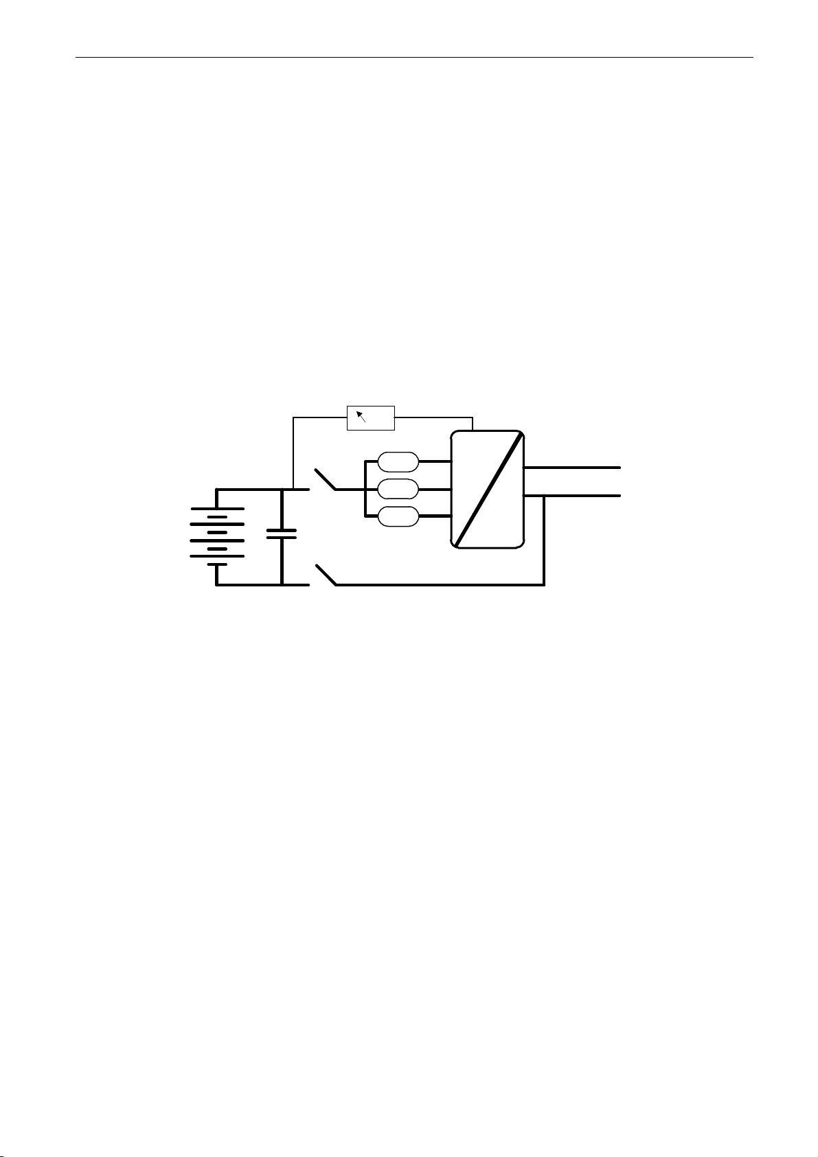
The DC/DC converter can be used to convert power between different DC-voltage levels. Typical
applications are power conversion between battery and DC-link of a drive system or grid converter.
The DC/DC converter can be used as a variable DC-voltage power supply.
This application requires the NXP3 control board and the VB761D version.
The capacitor and voltage measurements are optional, depending on the process requirements. The
measurement itself can be given via analogue input or trough fieldbus by power the management
system. The measurement is used to smoothen the start, because the voltage control can be started
at the correct level when it is known before start.
=
=
Vacon
DC-DC Converter
DC+
DC-
L
L
L
C
Source DC
DC-Link
Figure 1, DC/DC connection
Page 7

adfif101 dc/dc converter VACON® • 7
Local contacts: http://drives.danfoss.com/danfoss-drives/local-contacts/
Classified as Public
2. DC/DC APPLICATION COMPATIBILITY ISSUES
V093 & V094
- Compatibility note: Source voltage limits in current control mode are now operating as
limit regulators, thus it’s possible to charge or discharge source while voltage stays at
minimum or maximum limit. Read manual for updated descriptions or Source DC Voltage
limits. ADFIF101 DCDC New Source Voltage Limit Regulator
- Compatibility note: On start charging and discharging current limits are released with
ramp. default 1000,0 %/s
o P2.5.1.4 Charge Ramp Up ID1502
o P2.5.1.5 Discharge Ramp Up ID1532
-
Note 1: This application parameters are not kept backwards compatible if new features or
improvements would be difficult to implement by doing so. Read this change note and chapter
“Compatibility issues in parameters between versions” from manual before updating the application.
Note 2: It’s recommended to use compare function for parameter changes when updating application,
especially in cases when version number change is considerably high.
Application is constantly developed; this includes changing parameter default values, and if
parameters are directly downloaded to drive improved default values may be lost.
Page 8
8 • VACON® adfif101 dc/dc converter
Local contacts: http://drives.danfoss.com/danfoss-drives/local-contacts/
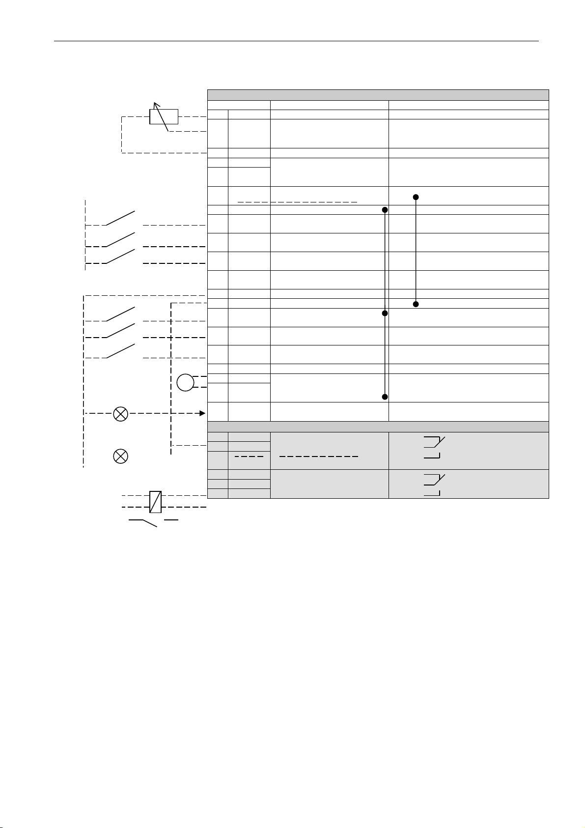
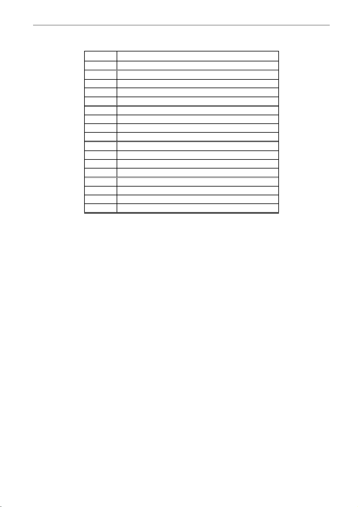
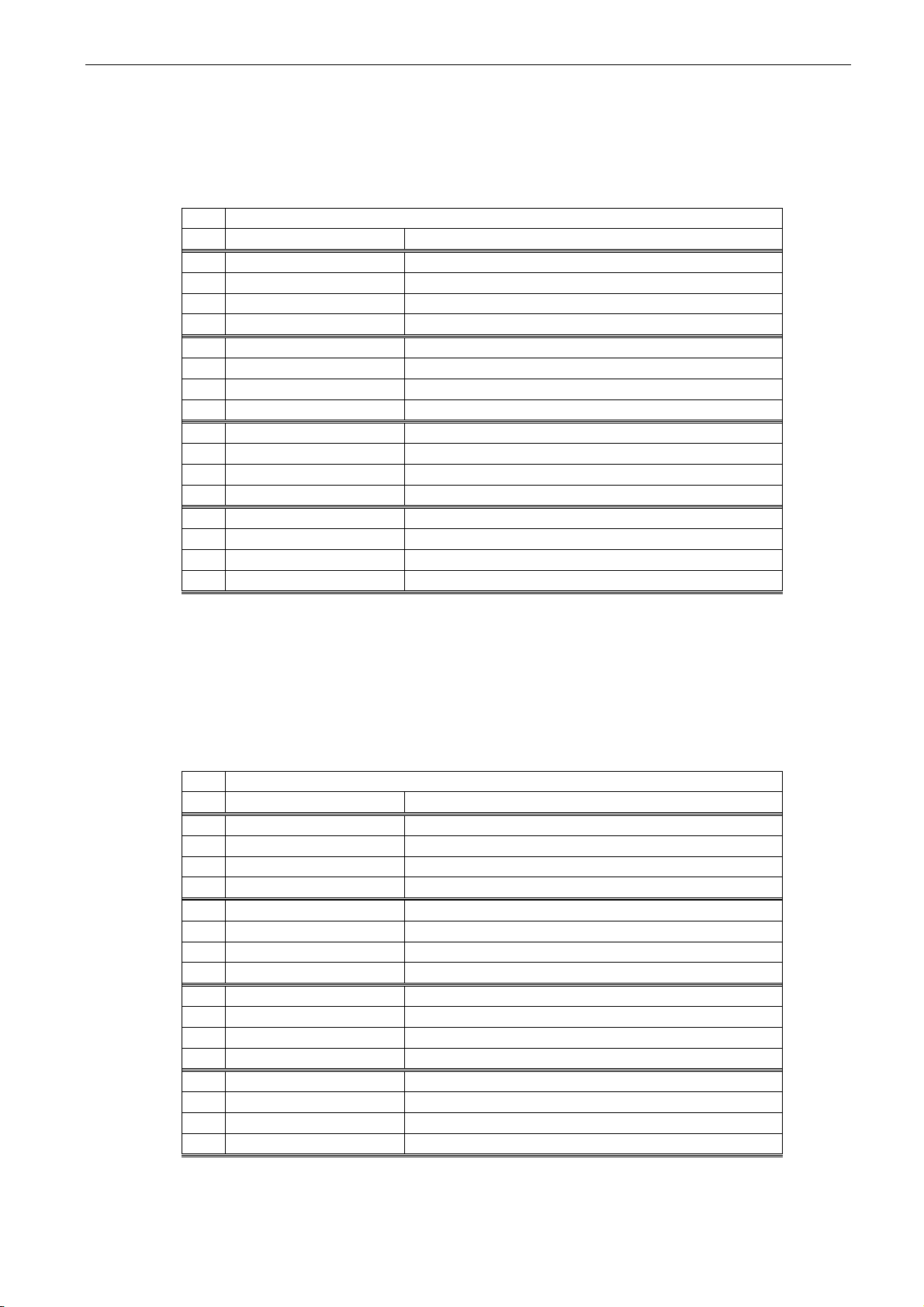
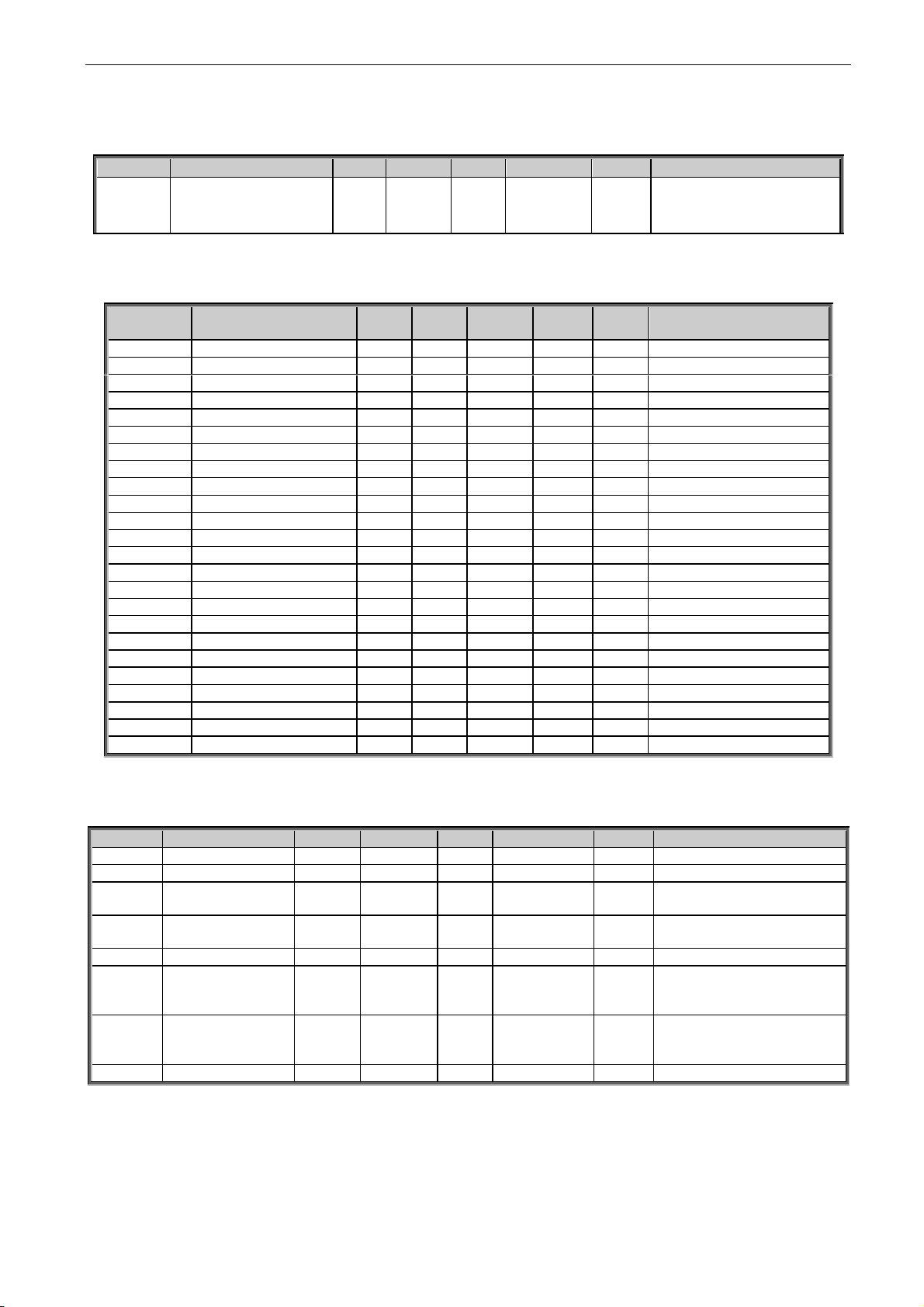
3. CONTROL IO
NXOPTA1
Terminal
Signal
Description
1
+10V
ref
Reference voltage output
Voltage for potentiometer, etc.
2
AI1+
Analogue input 1.
Range 0-10V, Ri = 200
Range 0-20 mA Ri = 250
Analogue input 1
Input range selected by jumpers.
Default range: Voltage 0 – 10 V
3
AI1-
I/O Ground
Ground for reference and controls
4
AI2+
Analogue input 2.
Range 0-10V, Ri = 200
Range 0-20 mA Ri = 250
Analogue input 2
Input range selected by jumpers.
Default range: Current 0 – 20 mA
5
AI2-
6
+24V
Control voltage output
Voltage for switches, etc. max 0.1 A
7
GND
I/O ground
Ground for reference and controls
8
DIN1
Start Request
Programmable G2.3.1
Contact closed = Start Request
9
DIN2
Programmable G2.3.1
No function defined at default
10
DIN3
Fault Reset
Programmable G2.3.1
Rising edge will reset active faults.
11
CMA
Common for DIN 1—DIN 3
Connect to GND or +24V
12
+24V
Control voltage output
Voltage for switches (see #6)
13
GND
I/O ground
Ground for reference and controls
14
DIN4
Programmable G2.3.1
No function defined at default
15
DIN5
Programmable G2.3.1
No function defined at default
16
DIN6
Programmable G2.3.1
No function defined at default
17
CMB
Common for DIN4—DIN6
Connect to GND or +24V
18
AOA1+
Analogue output 1
Programmable P2.3.1.2
Output range selected by jumpers.
Range 0—20 mA. RL, max. 500
Range 0—10 V. RL > 1k
19
AOA1-
20
DOA1
Digital output
Ready / Warning (Blinking)
Programmable
Open collector, I50mA, U48 VDC
NXOPTA2
21
RO1
Relay output 1
Programmable G2.4.1
Switching capacity
24 VCD / 8 A
250 VAC / 8 A
125 VDC / 0.4 A
22
RO1
23
RO1
24
RO2
Relay output 2
25
RO2
26
RO2
Table 3-1. Default I/O configuration.
220
VAC
mA
K1
K1
Page 9

adfif101 dc/dc converter VACON® • 9
Local contacts: http://drives.danfoss.com/danfoss-drives/local-contacts/
Classified as Public
4. DC/DC APPLICATION – MONITORING VALUES
On the next pages you will find the lists of parameters within the respective parameter groups.
Column explanations:
Code = Location indication on the keypad; Shows the operator the present parameter
number
Parameter = Name of parameter
Min = Minimum value of parameter
Max = Maximum value of parameter
Unit = Unit of parameter value; given if available
Default = Value preset by factory
Cust = Customer’s own setting
ID = ID number of the parameter
_____ = On parameter code: Parameter value can only be changed after the Drive has been
stopped.
_____ = Monitoring value is possible to control from fieldbus by ID number
The manual presents signals that are not normally visible for monitoring. i.e. is not a parameter or
standard monitoring signal. These signals are presented with [a letter]. e.g.
[FW]MotorRegulatorStatus
[V] Normal monitoring signal
[P] Normal parameter in application.
[FW] Firmware signal, Can be monitored with NCDrive when signal type is selected Firmware
[A] Application signal, can be monitored with NCDrive when signal type is selected Application.
[R] Reference type parameter on keypad.
[F] Function. Signal is received as an output of function.
[DI] Digital input signal.
Page 10
10 • VACON® adfif101 dc/dc converter
Local contacts: http://drives.danfoss.com/danfoss-drives/local-contacts/
4.1 Monitoring values
The monitoring values are the actual values of parameters and signals as well as statuses and
measurements. Monitoring values cannot be edited.
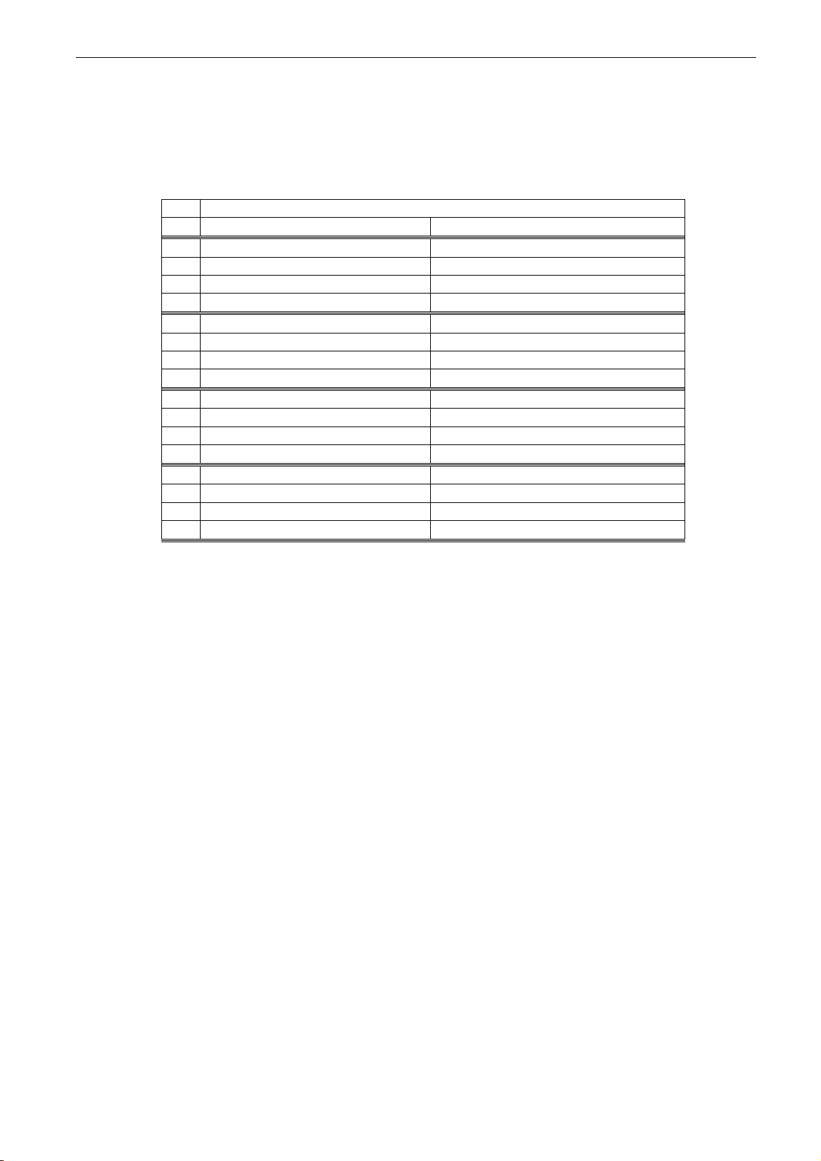
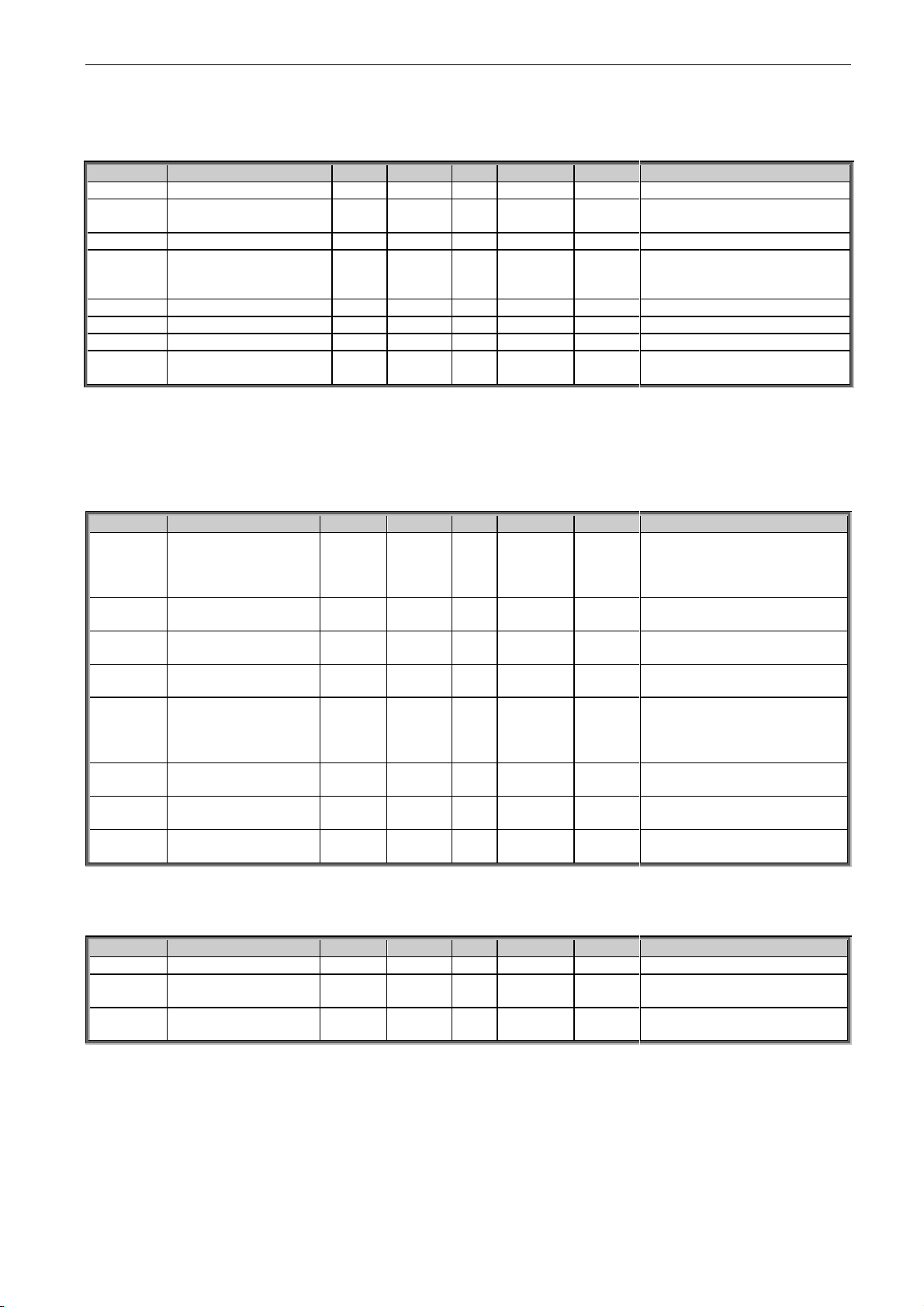
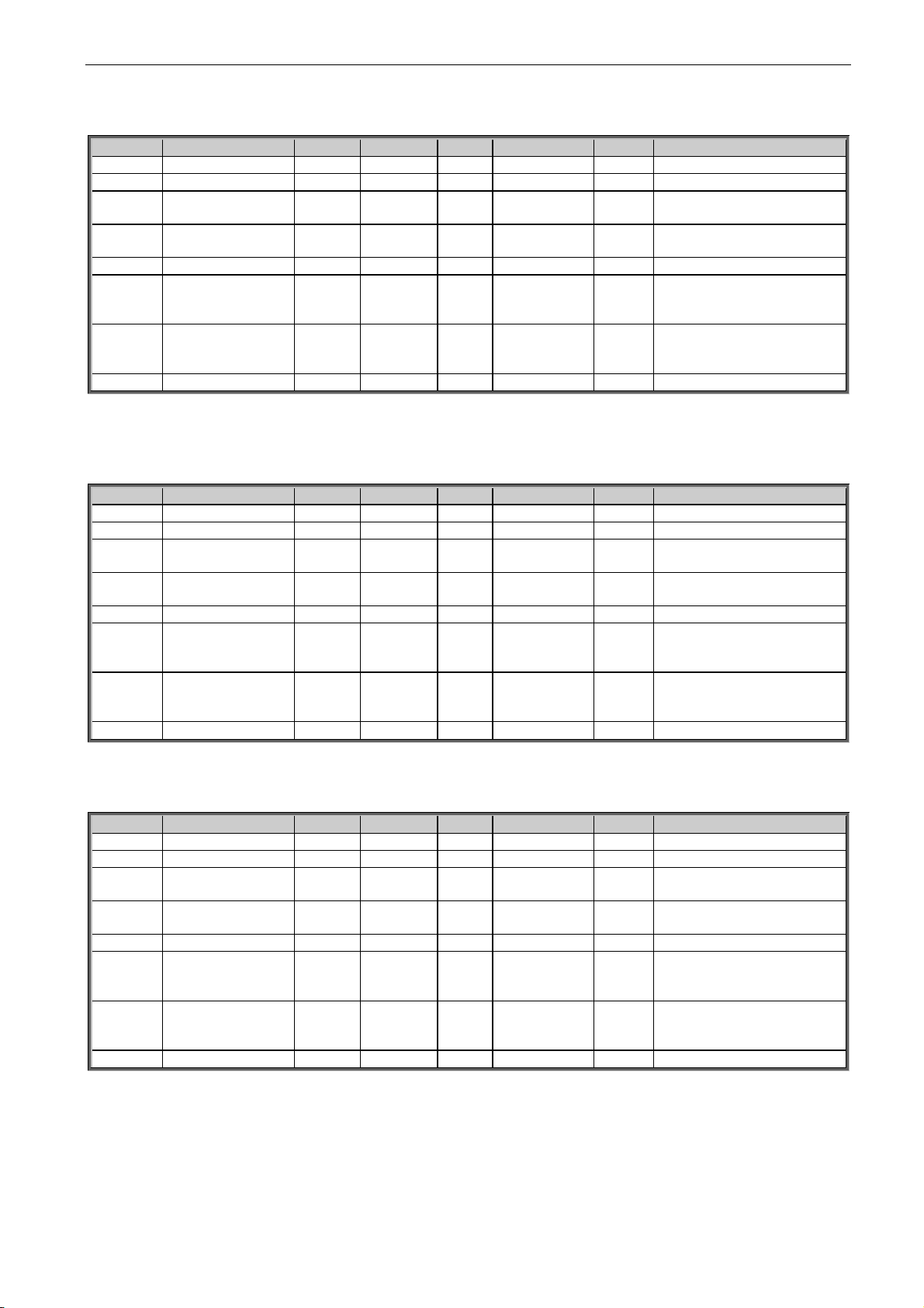
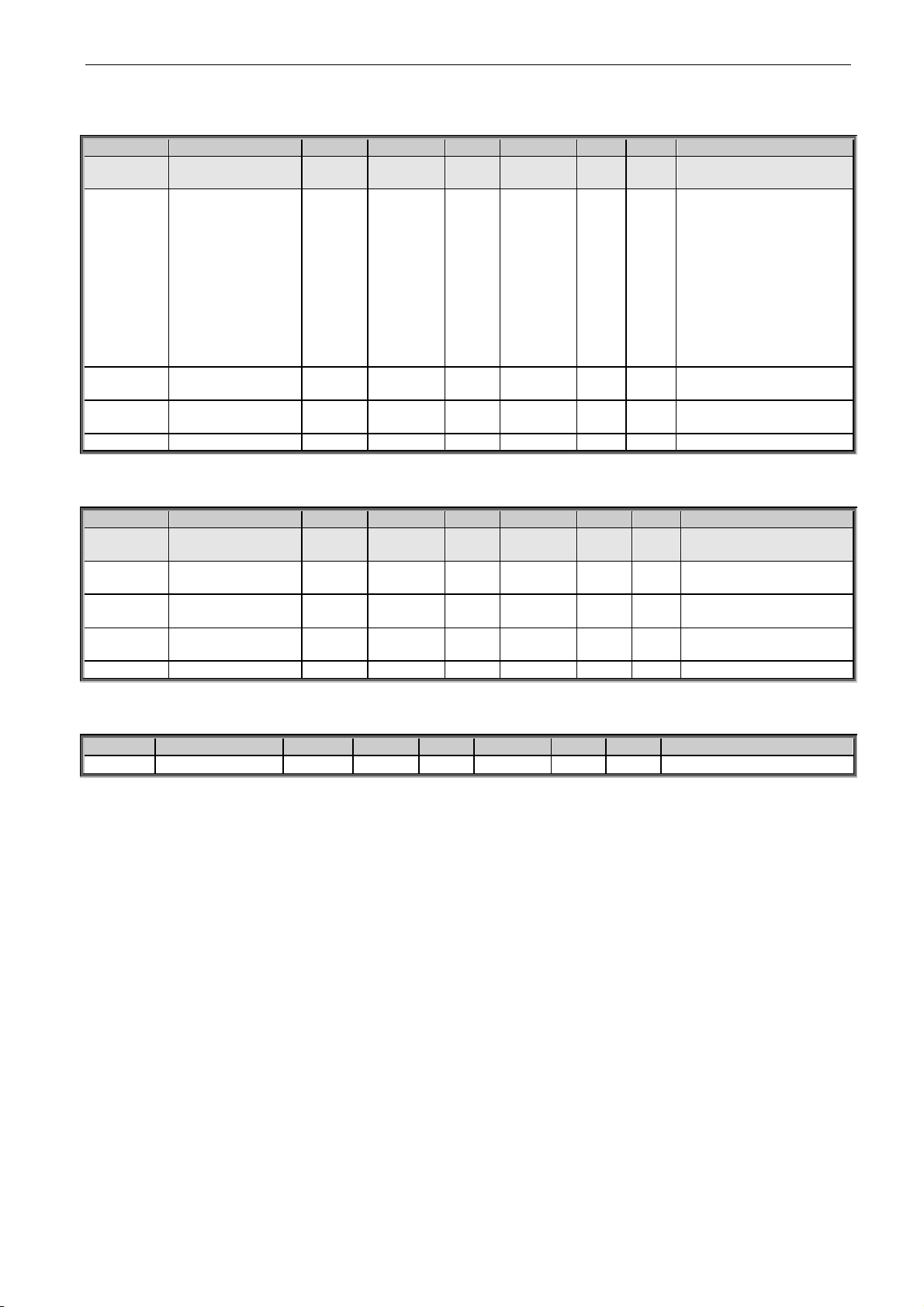
4.1.1 Monitoring 1
Code
Signal
Unit
Form.
ID
Description
V1.1
Source Current
A
Varies
1104
V1.2
Source Voltage
V
#,#
1107
Estimated at run state
V1.3
Active Current
Reference
%
#,#
1704
V1.4
Active Current
%
#,#
1125
Active current of the drive in % of Source
Nominal Current
> 0 Current from DC-Link To Source
< 0 Current from Source to DC-Link
V1.5
Source DC Ref.
%
#,##
606 V1.6
Source DC Act.
%
#,##
1873
Run state calculated, scaled.
V1.7
Source Meas. DC
%
#,##
1866 V1.8
Source Meas. Vdc
Vdc
#,#
1164
Voltage feedback signal selected in P2.6.4.1
V1.9
DC-Link Current
%
#,#
1861
V1.10
DC-Link Voltage
V # 1108
Measured DC Link voltage in Volts, filtered
V1.11
DC-Link Act.
%
#,##
7
Percentage of source nominal voltage
V1.12
Unit Temperature
°C
#
1109
Heatsink temperature
V1.13
Status Word
# 43
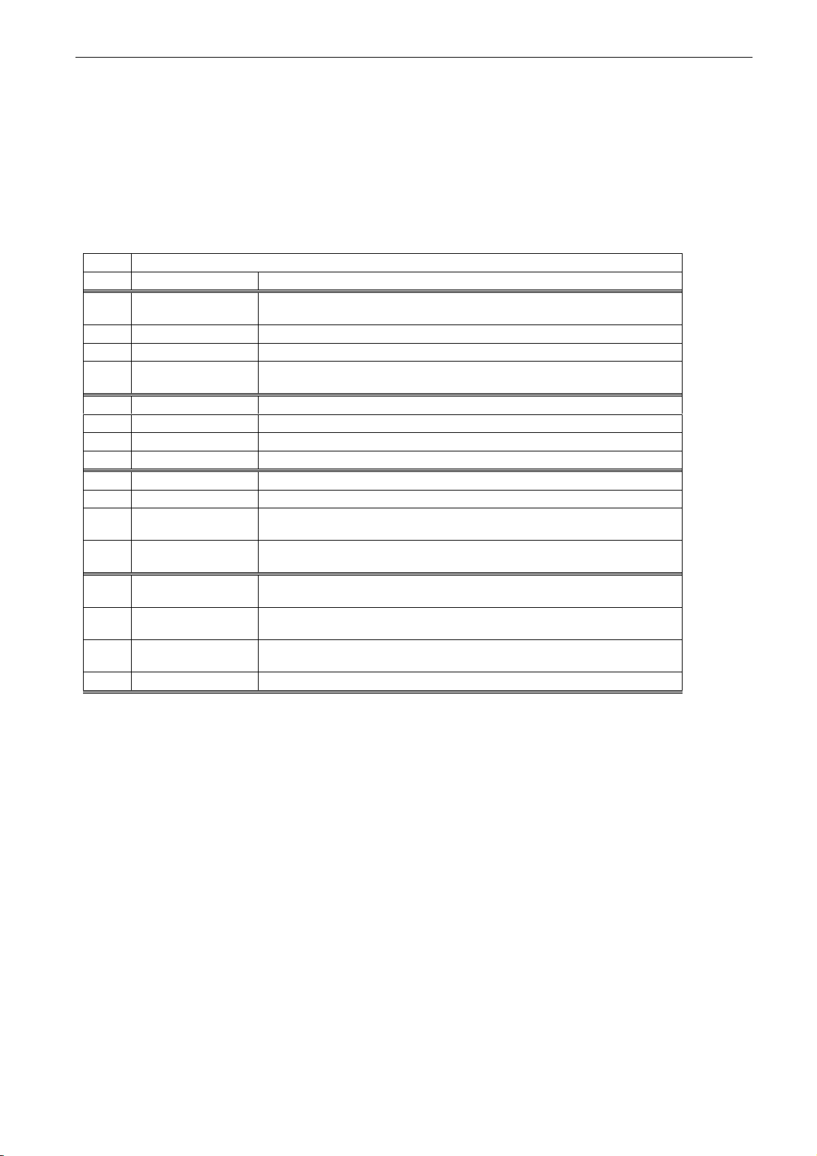
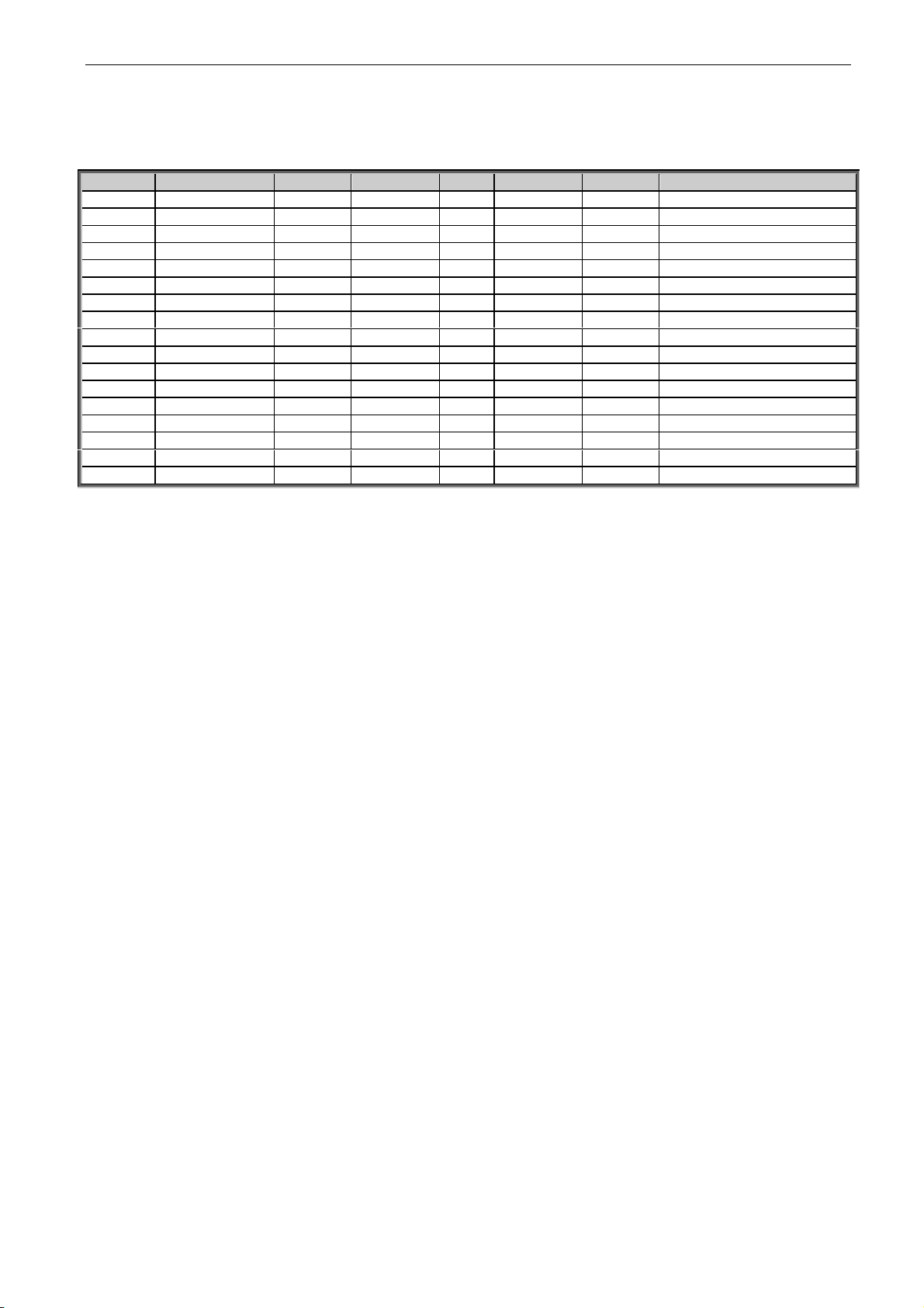
4.1.2 Monitoring 2 values
Code
Signal
Unit
Form.
ID
Description
V1.15.1
DC Voltage
V # 44
Unfiltered
V1.15.2
Current
A
Varies
1113
Unfiltered
V1.15.3
IU Current
%
#,#
1851
V1.15.4
IV Current
%
#,#
1852
V1.15.5
IW Current
%
#,#
1868
V1.15.6
Power kW
kW
Varies
1508
V1.15.7
Discharging Limit
%
#,#
1855
V1.15.8
Charging Limit
%
#,#
1854
V1.15.9
Mindex
%
#,##
1856
V1.15.10
Power Ref. %
%
#,#
1700
V1.15.11
Power Act. %
%
#,#
5 V1.15.12
DIN Status Word 1
# 56
V1.15.13
DIN Status Word 2
# 57
V1.15.14
Measured Temperature
Max
°C
#,#
42
V1.15.15
Meas. Temp 1
°C
#,#
51
V1.15.16
Meas. Temp 2
°C
#,#
52
V1.15.17
Meas. Temp 3
°C
#,#
53
V1.15.18
Meas. Temp 4
°C
#,#
69
V1.15.19
Meas. Temp 5
°C
#,#
70
V1.15.20
Meas. Temp 6
°C
#,#
71
Page 11
adfif101 dc/dc converter VACON® • 11
Local contacts: http://drives.danfoss.com/danfoss-drives/local-contacts/
Classified as Public
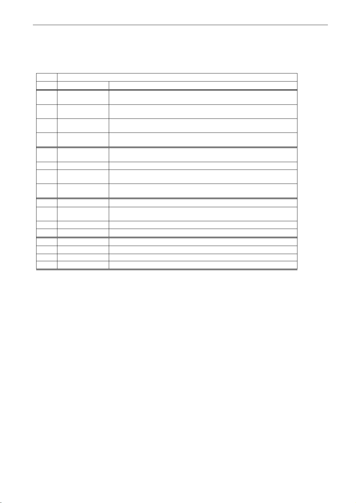
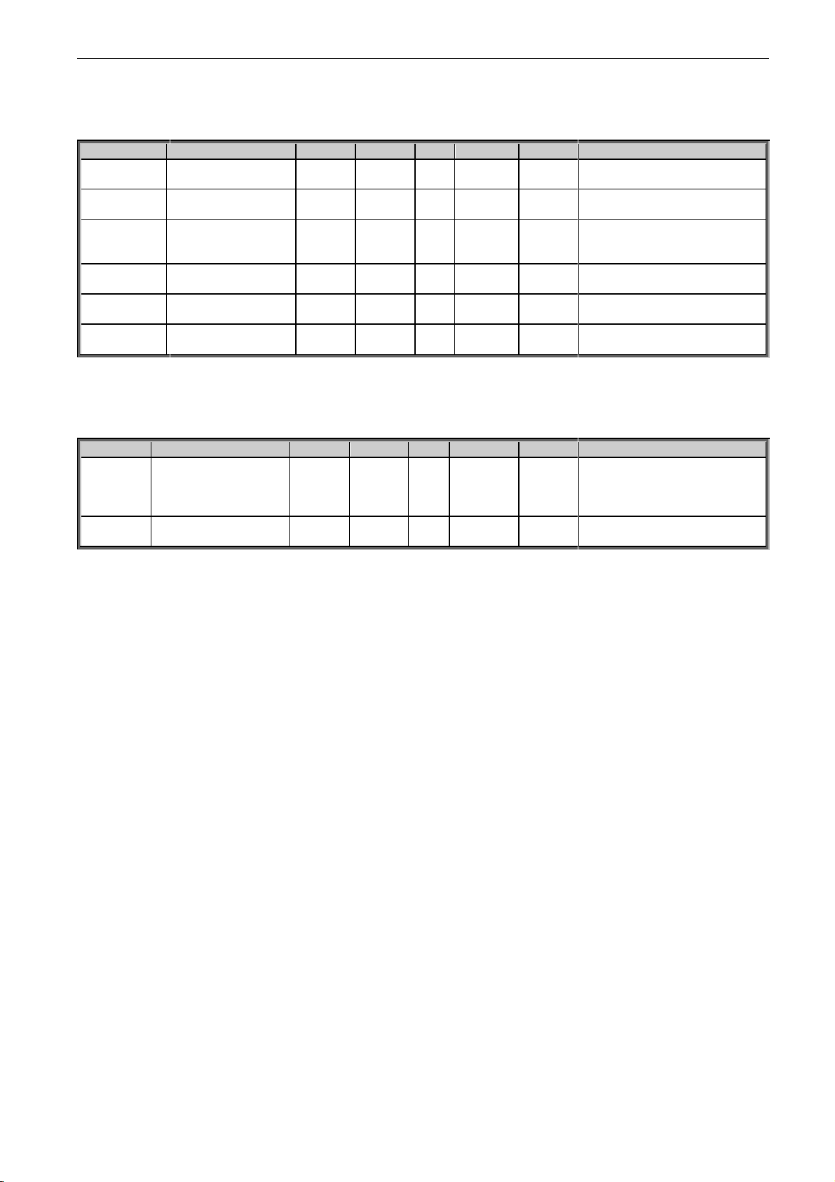
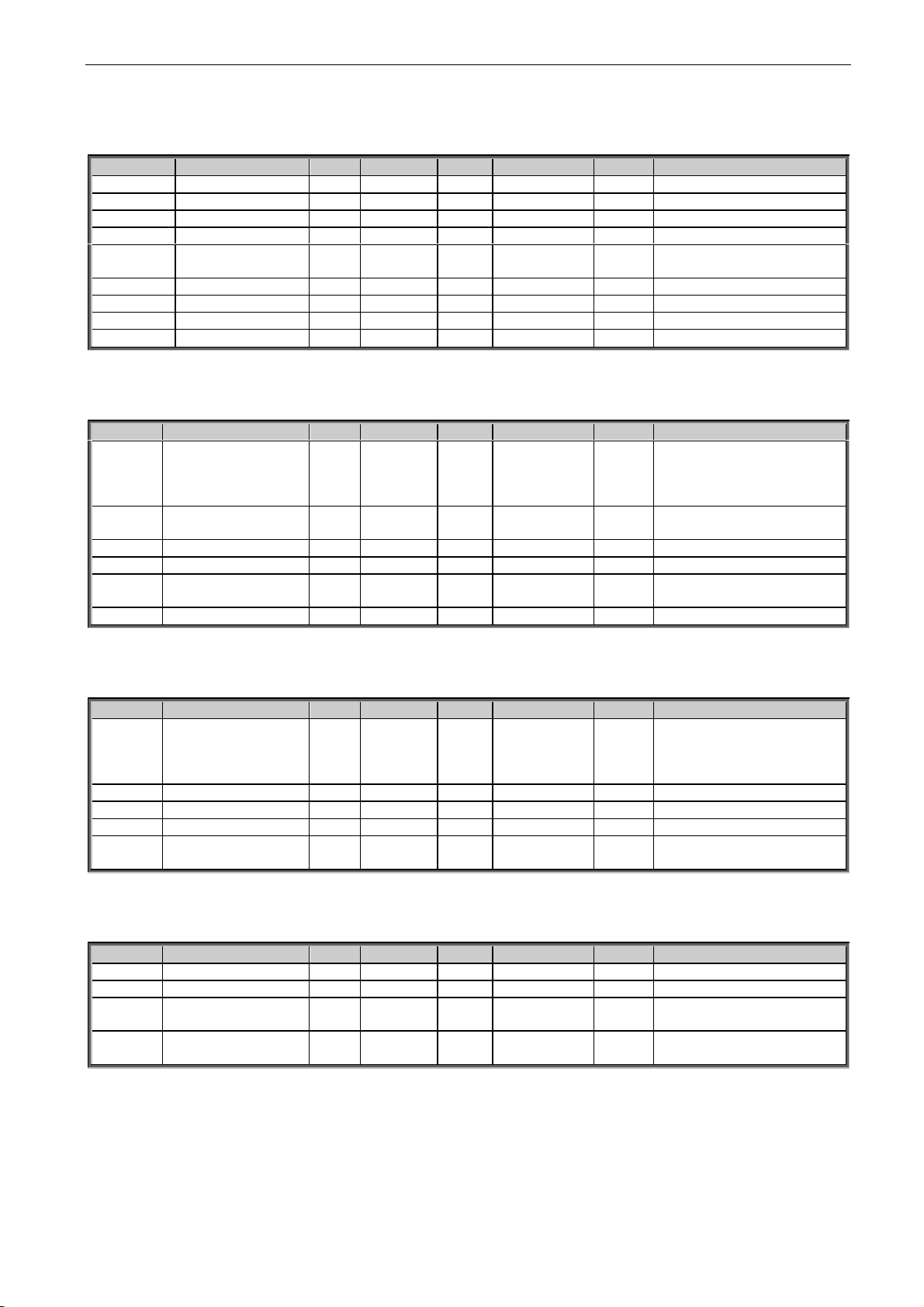
4.1.3 Fieldbus values
Code
Signal
Unit
Form.
ID
Description
V1.16.1
FB Control Word
# 1160
V1.16.2
FB Voltage Reference
%
#,##
875
V1.16.3
FB Status Word
# 68 V1.16.4
FB Current Reference
%
#,#
1140
V1.16.5
FB Power Reference
%
#,#
1141
V1.16.6
Warning No.
# 74 V1.16.7
Fault No.
# 37 V1.16.8
Fault Word 1
# 1172
V1.16.9
Fault Word 2
# 1173
V1.16.10
Warning Word 1
# 1174
V1.16.11
Analogue Input 1
#,##
13
V1.16.12
Analogue Input 2
#,##
14
V1.16.13
Analogue Input 3
#,##
27
V1.16.14
Analogue Input 4
#,##
28
V1.16.15
Analogue Output 1
#,##
26
V1.16.16
Analogue Output 2
#,##
31
V1.16.17
FB Analog Out
%
#,##
48
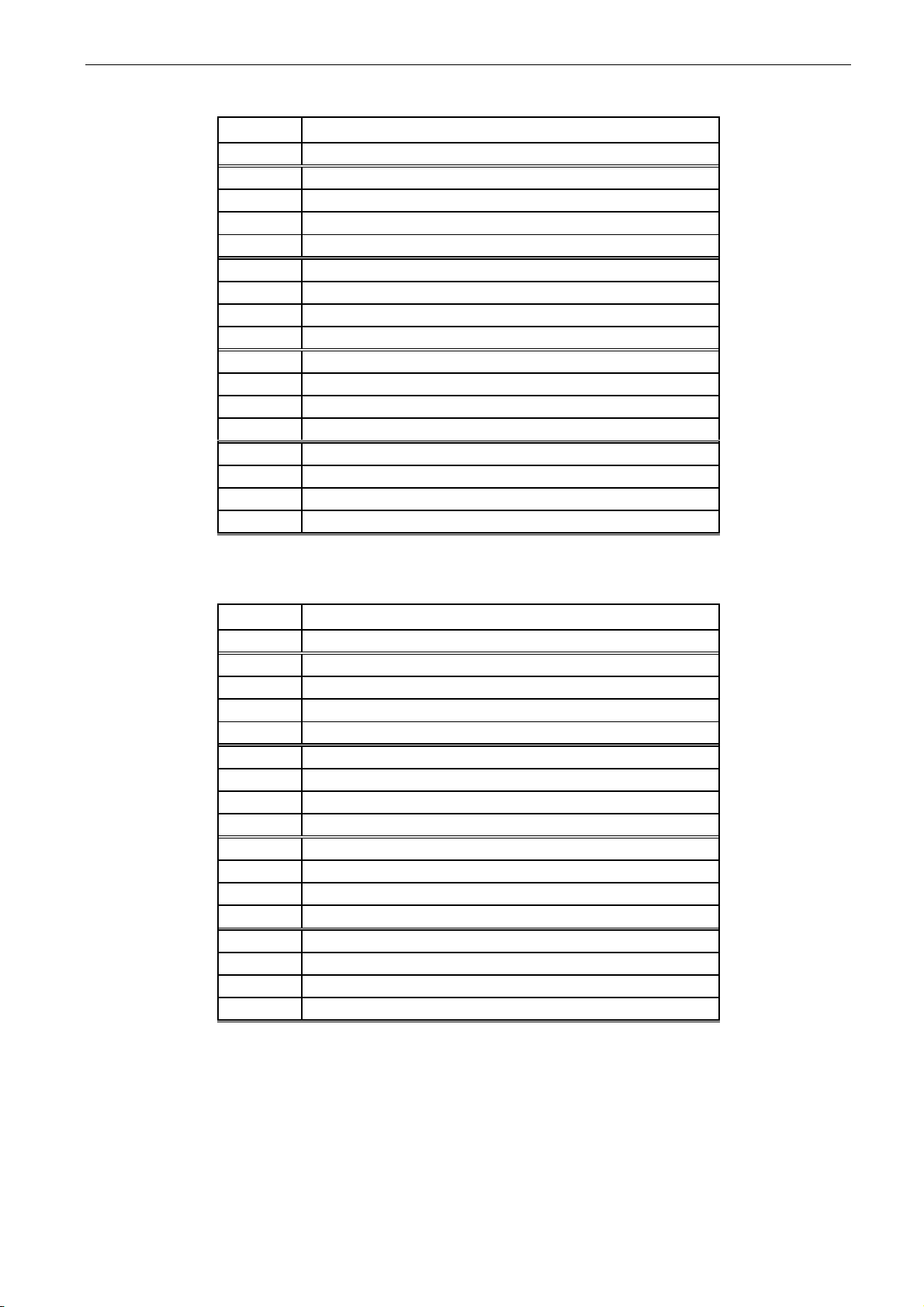
4.1.4 Master-Follower values
Code
Signal
Unit
Form.
ID
Description
V1.17.1
Master CW
# 93
Master Control Word
V1.17.2
Status Word D1
# 1615
V1.17.3
Status Word D2
# 1602
V1.17.4
Status Word D3
# 1603
V1.17.5
Status Word D4
# 1604
4.1.5 Voltage Reference Chain
Code
Signal
Unit
Form.
ID
Description
V1.18.1
Source DC Ref In
%
#,##
1127
Voltage reference before ramp
V1.18.2
Source DC Ref.
%
#,##
606
Voltage reference after ramp
V1.18.3
Source Ref. Final
%
#,##
1131
V1.18.4
Source Measured DC
%
#,##
1866
Page 12

12 • VACON® adfif101 dc/dc converter
Local contacts: http://drives.danfoss.com/danfoss-drives/local-contacts/
4.2 Monitoring Values description
4.2.1 Monitoring 1 values
V1.1 Source Current A ID1104
Sum current of all phases.
V1.2 Source Voltage V ID1107
Estimated source voltage. Value is update when drive is in run state.
V1.3 Active Current Reference % ID1704
Active current reference of the drive in percentage of Source Nominal Current.
Active Curr. Ref > 0: Current flow from Drive DC-Link to Source.
Active Curr. Ref < 0: Current flow from Source to Drive DC-Link.
V1.4 Active Current % ID1125
Active current of the drive in percentage of Source Nominal Current
Active Current > 0: Current flow from Drive DC-Link to Source.
Active Current < 0: Current flow from Source to Drive DC-Link.
V1.5 Source DC Ref. % ID606
DC Reference for the DC Source Voltage. Percentage of Source Nom Voltage
parameter.
V1.6 Source DC Act. % ID1873
DC Actual of the DC Source in percentage of Source Nom Voltage. Value is update
when drive is in run state.
V1.7 Source Measured DC % #,## ID1866
Measured DC Voltage.
If Source DC voltage is available by external measurement make connection to this by
Voltage feedback analogue input signal selected in P2.6.4.1.
If used Closed Loop Control and given trough fieldbus use Fast fieldbus communication
and FB Process Data In 1 channel for actual value by connecting to this monitoring
signal ID1866.
V1.8 Source Measured Vdc Vdc ID1164
Measured DC Voltage in Vdc for Closed Loop control and for starting voltage.
V1.9 DC-Link Current % ID1861
Calculated DC-Link Current in percentage of Source Nom Current.
V1.10 DC-Link Voltage V ID1108
Measured DC-link voltage in Vdc
V1.11 DC-Link Act. % ID7
Measured DC-Link voltage in percentage of Source Nom Voltage.
Page 13
adfif101 dc/dc converter VACON® • 13
Local contacts: http://drives.danfoss.com/danfoss-drives/local-contacts/
Classified as Public
V1.12 Unit Temperature °C ID1109
The highest measured drive temperature.
V1.13 Status Word ID43
Application Status Word combines different drive statuses to one data word.
Application Status Word ID43
FALSE
TRUE
b0
Closed Loop Control not active
Closed Loop Control active
b1
Not in Ready state
Ready
b2
Not Running
Running
b3
No Fault
Fault
b4
Discharging disabled, low voltage
Discharging Allowed
b5
Charging Disabled, high voltage
Charging Allowed
b6
Run Disabled
Run Enable
b7
No Warning
Warning
b8 Charging Switch closed (internal)
b9 Over Voltage Regulator Active
b10 Under Voltage regulator active.
b11
Quick Stop Not Active
Quick Stop Active
b12
No Run Request
Run Request
b13 One or more regulators active
b14
Current/Power Control Mode
Voltage Control Mode.
b15
4.2.2 Monitoring 2 values
V1.15.1 DC Voltage V ID44
Unfiltered DC-Link Voltage in V.
V1.15.2 Current A ID1113
Unfiltered source DC current in A.
V1.15.3 IU Current % ID1851
Unfiltered U phase current.
V1.15.4 IV Current % ID1852
Unfiltered U phase current.
V1.15.5 IW Current % ID1868
Unfiltered U phase current.
V1.15.6 Power kW kW ID1508
Calculated kW value of power flow.
Page 14

14 • VACON® adfif101 dc/dc converter
Local contacts: http://drives.danfoss.com/danfoss-drives/local-contacts/
V1.15.7 Discharge Limit % ID1855
Used Active discharge current limit, limit is showing 1/3 % of source nominal current. i.e.
limit is per phase.
V1.15.8 Charging Limit % ID1854
Used Active charge current limit, limit is showing 1/3 % of source nominal current. i.e.
limit is per phase.
V1.15.9 Mindex % ID 1856
Voltage reference as % of unit nominal voltage (500 V / 690 V)
V1.15.10 Power Ref. % % ID1700
Percentage power reference. Shown correctly when Power Control mode or Current
Control mode active.
V1.15.11 Power Act. % % ID5
Percentage power value scaled to Source Nom Power parameter.
V1.15.12 DIN Status 1 ID 56
V1.15.13 DIN Status 2 ID 57
DIN StatusWord 1
DIN StatusWord 2
b0
DIN: A.1
DIN: C.5
b1
DIN: A.2
DIN: C.6
b2
DIN: A.3
DIN: D.1
b3
DIN: A.4
DIN: D.2
b4
DIN: A.5
DIN: D.3
b5
DIN: A.6
DIN: D.4
b6
DIN: B.1
DIN: D.5
b7
DIN: B.2
DIN: D.6
b8
DIN: B.3
DIN: E.1
b9
DIN: B.4
DIN: E.2
b10
DIN: B.5
DIN: E.3
b11
DIN: B.6
DIN: E.4
b12
DIN: C.1
DIN: E.5
b13
DIN: C.2
DIN: E.6
b14
DIN: C.3
b15
DIN: C.4
V1.15.14 Measured Temperature °C ID42
Maximum temperature of the first used measurement board.
V1.15.15 Meas. Temp 1 °C #,# ID 51
V1.15.16 Meas. Temp 2 °C #,# ID 52
V1.15.17 Meas. Temp 3 °C #,# ID 53
V1.15.18 Meas. Temp 4 °C #,# ID 69
V1.15.19 Meas. Temp 5 °C #,# ID 70
V1.15.20 Meas. Temp 6 °C #,# ID 71
Separate measurement from two temperature measurement boards. The signal has 4 s
filtering time.
Page 15
adfif101 dc/dc converter VACON® • 15
Local contacts: http://drives.danfoss.com/danfoss-drives/local-contacts/
Classified as Public
4.2.3 Fieldbus monitoring values See detail descriptions from chapter Control and Status words
V1.16.1 FB Control Word ID 1160
Control word from fieldbus. Below table is for bypass operation for such fieldbus board that natively
supports this or can be parameterized to bypass mode. See details from chapter 8 Fieldbus profile for
Vacon DC/DC Drive.
FB Control Word ID1160
Bit
Signal
Comment
B00
DC Charge
0=
1= Charge DC
B01
B02
B03
Run
0= DC/DC Converter is stopped
1= DC/DC Converter is started
B04
B05
B06
B07
Reset
0>1 Reset fault.
B08
B09
B10
PLC Control
0= Disable FB Control
1= Enable FB Control
B11
FB DIN1 / WD
Can be used to control RO or directly parameter by ID number.
G2.4.1
B12
FB DIN2
Can be used to control RO or directly parameter by ID number.
G2.4.1
B13
FB DIN3
Can be used to control RO or directly parameter by ID number.
G2.4.1
B14
FB DIN4
Can be used to control RO or directly parameter by ID number.
G2.4.1
B15
V1.16.2 FB Voltage Reference [%] ID875
Voltage reference from fieldbus. Connection to here is made with ID number with
Fieldbus data mapping.
Page 16
16 • VACON® adfif101 dc/dc converter
Local contacts: http://drives.danfoss.com/danfoss-drives/local-contacts/
V1.16.3 FB Status Word ID 68
Status word to fieldbus. Below table is for bypass operation for such fieldbus board that natively
supports this or can be parameterized to bypass mode.
FB Status Word ID68
Signal
Comment
B00
Ready On
0=Drive not ready to switch on
1=Drive ready to start charging
B01
Ready Run
0=Drive not ready to run
1=Drive ready and Main Contactor is ON
B02
Running
0=Drive not running
1=Drive in Run state (Modulating)
B03
Fault
0=No active fault
1=Fault is active
B04
Run Enable
Status
0= Run Disabled. Drive in stop state
1= Run Enabled. Drive can be started.
B05
B06
Inhibit
0= Drive in operating condition.
1= Run disabled or fault state.
B07
Warning
0= No active warnings
1= Warning active
B08
B09
Fieldbus Control
Active
0=Fieldbus control not active
1=Fieldbus control active
B10
B11
B12
B13
B14
B15
WD Pulse
Feedback from FB Control Word B11
V1.16.4 FB Current Reference [%] ID1140
Current reference from fieldbus. Connection to here is made with ID number with
Fieldbus data mapping.
V1.16.5 FB Power Reference [%] ID1141
Power reference from fieldbus. Connection to here is made with ID number with Fieldbus
data mapping.
V1.16.6 Warning No. ID74
Number if last active warning.
V1.16.7 Fault No. ID37
Number if last active fault.
Page 17
adfif101 dc/dc converter VACON® • 17
Local contacts: http://drives.danfoss.com/danfoss-drives/local-contacts/
Classified as Public
V1.16.8 Fault Word 1 ID1172
Fault Word 1 ID1172
Bit
Fault(s)
B0
F1 Over current, F31 IGBT, F41 IGBT
B1
F2 Over Voltage
B2
F9 Under Voltage
B3 B4
F3 Earth Fault
B5
B6
F14 Unit Over Temperature
B7
F29 Thermistor
B8
B9
B10
B11
F52 Keypad or F52 PC communication fault
B12
F53 FieldBus fault
B13
B14
F54 Slot Communication fault
B15
F50 4mA fault
V1.16.9 Fault Word 2 ID 1173
Fault Word 2 ID1173
Bit
Fault(s)
B0 B1 B2 B3 B4 B5
B6
F51 External fault
B7
B8
B9
F31 IGBT, F41 IGBT
B10
B11
B12
B13 B14 B15
Page 18
18 • VACON® adfif101 dc/dc converter
Local contacts: http://drives.danfoss.com/danfoss-drives/local-contacts/
V1.16.10 Warning Word 1 ID 1174
Warning Word 1 ID1174
Bit
Warning(s)
B0
B1
W29 Thermistor
B2
B3
B4
B5
B6
F53 FB Warning
B7 B8
F14 Over Temperature
B9 B10 B11
W63 or F63 Quick Stop
B12
W62 or F62 Run Disabled
B13
B14
B15
V1.16.11 Analogue input 1 % ID 13
V1.16.12 Analogue input 2 % ID 14
Unfiltered analogue input level.
0 % = 0 mA / 0 V, -100 % = -10 V, 100 % = 20 mA / 10 V.
Monitoring scaling is determined by the option board parameter.
V1.16.13 Analogue input 3 % ID 27
V1.16.14 Analogue input 4 % ID 28
It is possible to adjust this input value from fieldbus when the input terminal selection is
0.1. This way it is possible to adjust the free analogue input from fieldbus and have all
analogue input functions available for fieldbus process data.
V1.16.15 Analogue Out 1 % ID 26
V1.16.16 Analogue Out 2 % ID 31
Analogue Output value 0 % = 0 mA / 0 V, 100 % = 20 mA / 10 V
V1.16.17 FB Analog Out % #,## ID48
Page 19
adfif101 dc/dc converter VACON® • 19
Local contacts: http://drives.danfoss.com/danfoss-drives/local-contacts/
Classified as Public
4.2.4 Master-Follower monitoring values
V1.17.1 Master CW ID93
SystemBus Master Control word that is send by master drive and received by follower
drives.
Master Control Word ID93
Signal
Comment
b0
b1
b2
b3
Fault Reset
b4
Master Running
b5
b6
b7
WD Pulse
b8
b9
Datalogger Trig command
b10
b11
b12
b13
b14
Voltage Control
b15
V1.17.2 Status Word D1 ID1615
V1.17.3 Status Word D2 ID1602
V1.17.4 Status Word D3 ID1603
V1.17.5 Status Word D4 ID1604
Follower status words received by SystemBus master drive from followers.
Follower Status Word
Signal
Comment
b0
b1
Ready
b2
Run b3
Fault
b4
Charge SW State
b5
b6
Run Enable
b7
Warning
b8
b9
b10
Synchronized
b11
b12
Run Request
b13
Limit Regulator
b14
b15
WD Pulse
Page 20

20 • VACON® adfif101 dc/dc converter
Local contacts: http://drives.danfoss.com/danfoss-drives/local-contacts/
4.2.5 Voltage Reference Chain
V1.18.1 Source DC Ref. In % ID1127
DC Reference for the DC Source voltage before the ramp.
V1.18.2 Source DC Ref. % ID606
DC Reference for the DC Source Voltage after the ramp. Percentage of Source Nom
Voltage parameter.
V1.18.3 Source Ref. Final % ID1131
DC Reference for the DC Source Voltage after Closed Loop PI controller.
V1.18.4 Source Measured DC % ID1866
Measured DC Voltage.
If Source DC voltage is available by external measurement make connection to this by
Voltage feedback analogue input signal selected in P2.6.4.1.
If used Closed Loop Control and given trough fieldbus use Fast fieldbus communication
and FB Process Data In 1 channel for actual value.
Page 21
adfif101 dc/dc converter VACON® • 21
Local contacts: http://drives.danfoss.com/danfoss-drives/local-contacts/
Classified as Public
5. PARAMETER LIST
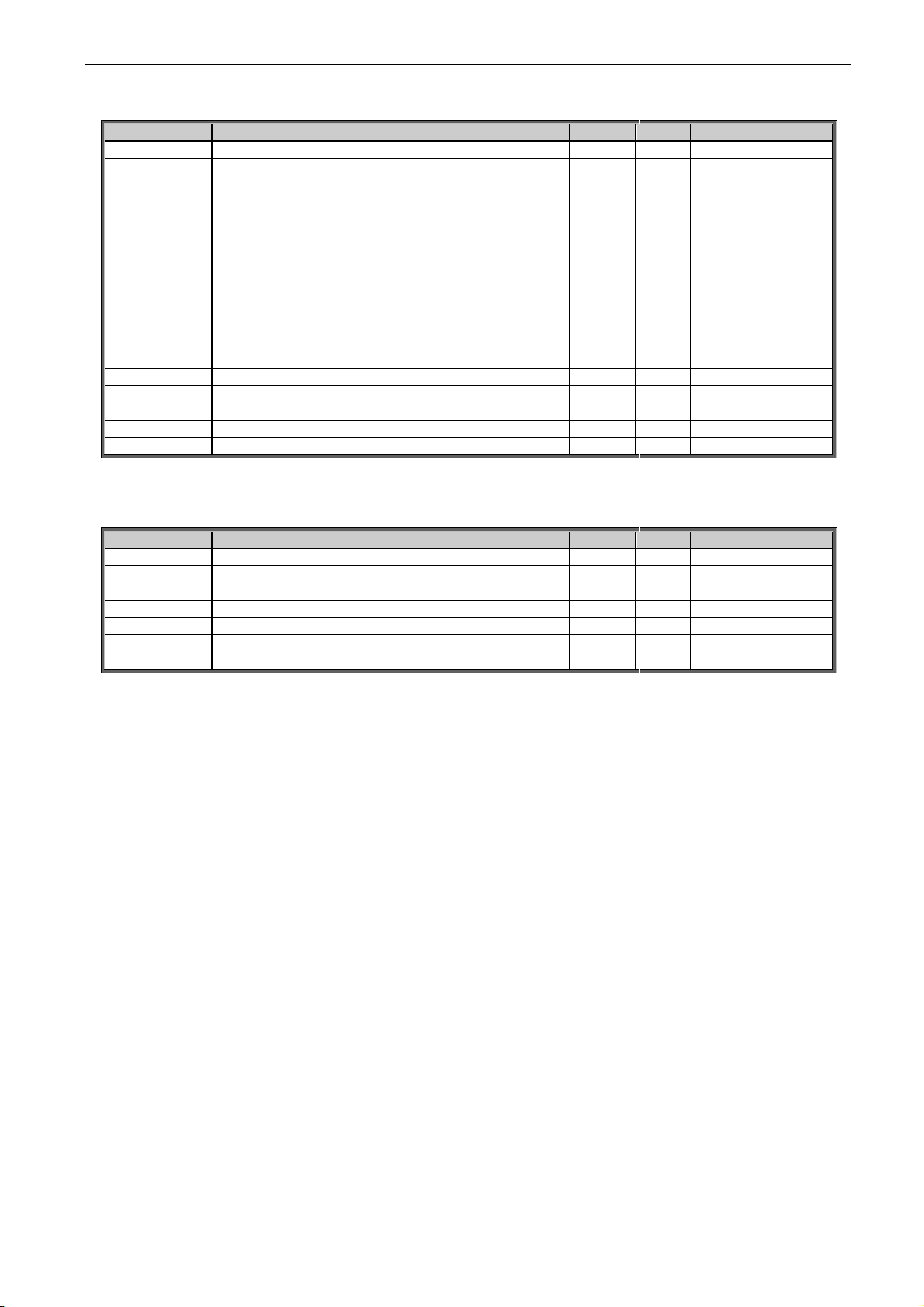
5.1 Basic parameters
Code
Parameter
Min
Max
Unit
Default
ID
Note
P2.1.1
Source Nom Current
0,0
Varies
A
Varies
113
Capacity of supply,
P2.1.2
Source Nom Voltage
50
797
1099
V
400
690
110
P2.1.3
Source Nom Power
0
32000
kW 0 116
P2.1.4
Control Mode
0 2 0 1858
0 = Current
1 = Voltage
2 = Power
P2.1.5
Voltage Reference
0
320 % 100
1462
P2.1.6
Current Reference
-150
150 % 0
1860
Common current reference
P2.1.7
Power Reference
-150
150 % 0
1869
Common power reference
P2.1.8
Identification
0 1 0 631
0 = No Action
1 = Current. Meas. Offset.
Table 5-1. Basic parameters
5.2 Reference Handling
5.2.1 Reference Handling
Code
Parameter
Min
Max
Unit
Default
ID
Note
P2.2.1
IO Control Mode
0 3 0 1856
0 = Control Mode P2.1.4
1 = Current Control
2 = Voltage Control
3 = Power Control
P2.2.2
IO Voltage Ref Sel.
0 1 0 117
0 = Voltage Ref. ID1462
1 = FB Voltage Ref. ID875
P2.2.3
IO Current Ref. Sel.
0 1 0 131
0 = Current Ref. ID1860
1 = FB Current Ref. ID1140
P2.2.4
IO Power Ref. Sel.
0 1 0 1620
0 = Power Ref. ID1869
1 = FB Power Ref. ID1141
P2.2.5
FB Control Mode
0 3 0 1848
0 = Control Mode ID1858
1 = Current Control
2 = Voltage Control
3 = Power Control
P2.2.6
FB Voltage Ref Sel.
0 1 0 112
0 = Voltage Ref. ID1462
1 = FB Voltage Ref. ID875
P2.2.7
FB Current Ref. Sel.
0 1 0 641
0 = Current Ref. ID1860
1 = FB Current Ref. ID1140
P2.2.8
FB Power Ref. Sel.
0 1 0 1621
0 = Power Ref. ID1869
1 = FB Power Ref. ID1141
Table 5-2. Current Reference Handling
5.2.2 Voltage Reference
Code
Parameter
Min
Max
Unit
Default
ID
Note
P2.2.9.1
Drooping
0
100 % 0
620
P2.2.9.2
Voltage Reference
Ramp Rate
-1
3200
%/s 5 1867
<0 = No ramp
P2.2.9.3
Direct Vdc Control
0 1 0 1743
0 = No
1 = Yes
Table 5-3. Voltage Reference Handling
Page 22
22 • VACON® adfif101 dc/dc converter
Local contacts: http://drives.danfoss.com/danfoss-drives/local-contacts/
5.2.3 Current Reference
Code
Parameter
Min
Max
Unit
Default
ID
Note
P2.2.10.1
Constant Reference
1
-320,00
320,00
%
0,0
1239
P2.2.10.2
Constant Reference
2
-320,00
320,00
%
0,0
1240
P2.2.10.3.1
Phase Reference
Mode
0 2 0 1859
0 = Average
1 = Individual
2 = Same
P2.2.10.3.2
IU Current
Reference
-300
300 % 0
128
P2.2.10.3.3
IV Current
Reference
-300
300 % 0
129
P2.2.10.3.4
IW Current
Reference
-300
300 % 0
130
Table 5-4. Current Reference Handling
5.2.4 Start Reference Handling
Code
Parameter
Min
Max
Unit
Default
ID
Note
P2.2.11.1
Voltage Reference At
Start
0 2 3 1864
0 = Reference
1 = Start Voltage Reference
2 = Measurement
3 = 80 %
P2.2.11.2
Start Voltage
Reference
0
320 % 90
1865
Table 5-4. Start Reference Handling
Page 23
adfif101 dc/dc converter VACON® • 23
Local contacts: http://drives.danfoss.com/danfoss-drives/local-contacts/
Classified as Public
5.3 Input signals
5.3.1 Basic Settings
Code
Parameter
Min
Max
Unit
Default
ID
Description
P2.3.1.1
Start/Stop Logic
0 2 0 300
0 = Start-No Act
1 = RPuls-FPuls
2 = RPuls-RPuls
Table 5-5. Basic Settings
5.3.2 Digital inputs
Code
Parameter
Min
Max
Unit
Defaul
t
ID
Description
P2.3.1.1
Start Signal 1
0.1
E.10
DigIn
A.1
403 P2.3.2.2
Start Signal 2
0.1
E.10
DigIn
0.1
404 P2.3.2.3
Run Enable
0.1
E.10
DigIn
0.2
407 P2.3.2.4
Fault Reset
0.1
E.10
DigIn
A.3
414 P2.3.2.5
External fault
0.1
E.10
DigIn
0.1
405 P2.3.2.6
External fault
0.1
E.10
DigIn
0.1
406 P2.3.2.7
Enable Constant Ref
0.1
E.10
DigIn
0.1
532 P2.3.2.8
Constant Ref. 1
0.1
E.10
DigIn
0.1
530 P2.3.2.9
Constant Ref. 2
0.1
E.10
DigIn
0.1
531
P2.3.2.10
I/O Term Control
0.1
E.10
DigIn
0.1
409
P2.3.2.11
Keypad Control
0.1
E.10
DigIn
0.1
410
P2.3.2.12
Fieldbus Control
0.1
E.10
DigIn
0.1
411
P2.3.2.13
DC CB State
0.1
E.10
DigIn
0.1
1453
P2.3.2.14
Thermal Switch
0.1
E.10
DigIn
0.2
1179
P2.3.2.15
Quick Stop
0.1
E.10
DigIn
0.2
1213
P2.3.2.16
Charge Limit 1
0.1
E.10
DigIn
0.1
1500
P2.3.2.17
Charge Limit 2
0.1
E.10
DigIn
0.1
1501
P2.3.2.18
Discharge Limit 1
0.1
E.10
DigIn
0.1
1506
P2.3.2.19
Discharge Limit 2
0.1
E.10
DigIn
0.1
1624
P2.3.2.20
Cooling Monitor
0.1
E.10
DigIn
0.2
750
P2.3.2.21
Klixon In 1
0
E.10
DigIn
0.2
780
P2.3.2.22
Klixon In 2
0
E.10
DigIn
0.2
781
P2.3.2.23
Input Switch
0
E.10
DigIn
0.2
1209
P2.3.2.24
Ambient Temp
0
E.10
DigIn
0.2
783
Table 5-6. Digital inputs parameters
5.3.3 Analogue Input 1
Code
Parameter
Min
Max
Unit
Default
ID
Note
P2.3.3.1
AI1 signal selection
0.1
E.10 0.1
377
P2.3.3.2
AI1 filter time
0,000
32,000
s
0,000
324
P2.3.3.3
AI1 custom
minimum setting
-160,00
160,00 % 0,00
321
P2.3.3.4
AI1 custom
maximum setting
-160,00
160,00
%
100,00
322
P2.3.3.5
AI1 signal inversion
0 1 0 387
P2.3.3.6
AI1 reference
scaling, minimum
value
-32000
32000 0
303
P2.3.3.7
AI1 reference
scaling, maximum
value
-32000
32000 0
304
P2.3.3.8
AI1 Controlled ID
0
10000 0
1507
Table 5-7. ANALOG INPUT 1,
Page 24
24 • VACON® adfif101 dc/dc converter
Local contacts: http://drives.danfoss.com/danfoss-drives/local-contacts/
5.3.4 Analogue Input 2
Code
Parameter
Min
Max
Unit
Default
ID
Note
P2.3.4.1
AI2 signal selection
0.1
E.10 0.1
388
P2.3.4.2
AI2 filter time
0,000
32,000
s
0,000
329
P2.3.4.3
AI2 custom
minimum setting
-160,00
160,00 % 0,00
326
P2.3.4.4
AI2 custom
maximum setting
-160,00
160,00
%
100,00
327
P2.3.4.5
AI2 signal inversion
0 1 0 398
P2.3.4.6
AI2 reference
scaling, minimum
value
-32000
32000 0
393
P2.3.4.7
AI2 reference
scaling, maximum
value
-32000
32000 0
394
P2.3.4.8
AI2 Controlled ID
0
10000 0
1511
Table 5-8. ANALOG INPUT 2,
5.3.5 Analogue Input 3
Code
Parameter
Min
Max
Unit
Default
ID
Note
P2.3.5.1
AI3 signal selection
0.1
E.10 0.1
141
P2.3.5.2
AI3 filter time
0,000
32,000
s
0,000
142
P2.3.5.3
AI3 custom
minimum setting
-160,00
160,00 % 0,00
144
P2.3.5.4
AI3 custom
maximum setting
-160,00
160,00
%
100,00
145
P2.3.5.5
AI3 signal inversion
0 1 0 151
P2.3.5.6
AI3 reference
scaling, minimum
value
-32000
32000 0
1037
P2.3.5.7
AI3 reference
scaling, maximum
value
-32000
32000 0
1038
P2.3.5.8
AI3 Controlled ID
0
10000 0
1509
Table 5-9. ANALOG INPUT 3,
5.3.6 Analogue Input 4
Code
Parameter
Min
Max
Unit
Default
ID
Note
P2.3.6.1
AI4 signal selection
0.1
E.10 0.1
152
P2.3.6.2
AI4 filter time
0,000
32,000
s
0,000
153
P2.3.6.3
AI4 custom
minimum setting
-160,00
160,00 % 0,00
155
P2.3.6.4
AI4 custom
maximum setting
-160,00
160,00
%
100,00
156
P2.3.6.5
AI4 signal inversion
0 1 0 162
P2.3.6.6
AI4 reference
scaling, minimum
value
-32000
32000 0
1039
P2.3.6.7
AI4 reference
scaling, maximum
value
-32000
32000 0
1040
P2.3.6.8
AI4 Controlled ID
0
10000 0
1510
Table 5-10. ANALOG INPUT 4,
Page 25

adfif101 dc/dc converter VACON® • 25
Local contacts: http://drives.danfoss.com/danfoss-drives/local-contacts/
Classified as Public
5.3.7 Input options
Code
Parameter
Min
Max
Unit
Default
ID
Note
P2.3.7.1
DI Inversion
0
65535 0
1091
Table 5-10. Input options
Page 26
26 • VACON® adfif101 dc/dc converter
Local contacts: http://drives.danfoss.com/danfoss-drives/local-contacts/
5.4 Output signals
5.4.1 Digital Outputs
Code
Parameter
Min
Max
Unit
Default
ID
Description
2.4.1.1
Ready
0.1
E.10
DiOut 432
2.4.1.2
Running
0.1
E.10
DiOut 433
2.4.1.3
Fault
0.1
E.10
DiOut 434
2.4.1.4
Fault, Inverted
0.1
E.10
DiOut 435
2.4.1.5
Warning
0.1
E.10
DiOut 436
2.4.1.6
FB Dig Input 1
0.1
E.10
DiOut 455
2.4.1.7
FB DIN 1 Par ID
0.1
E.10
DiOut 891
2.4.1.8
FB Dig Input 2
0.1
E.10
DiOut 456
2.4.1.9
FB DIN 2 Par ID
0.1
E.10
DiOut 892
2.4.1.10
FB Dig Input 3
0.1
E.10
DiOut 457
2.4.1.11
FB DIN 3 Par ID
0.1
E.10
DiOut 893
2.4.1.12
FB Dig Input 4
0.1
E.10
DiOut 169
2.4.1.13
FB DIN 4 Par ID
0.1
E.10
DiOut 894
2.4.1.14
Charge DC
0.1
E.10
DiOut 1668
2.4.1.15
DC Ready
0.1
E.10
DiOut 1218
2.4.1.16
Charging
0.1
E.10
DiOut 1219
2.4.1.17
Discharging
0.1
E.10
DiOut 1220
Table 5-11. Digital outputs parameters
Page 27
adfif101 dc/dc converter VACON® • 27
Local contacts: http://drives.danfoss.com/danfoss-drives/local-contacts/
Classified as Public
5.4.2 Analogue Output 1
Code
Parameter
Min
Max
Unit
Default
ID
Description
P2.4.2.1
Iout 1 Signal
0.1
E.10
AnOUT
0.1
464
P2.4.2.2
Iout 1 Content
0 8 0 307
0= 4 mA
1=±2*Active Current
2=Source Voltage
3=Measured Source
Voltage
4=DC Voltage
Unfiltered
5=DC Current
6= Power
7=FB Analogue
Input ID48
8=Value Control
Output
P2.4.2.3
Iout 1 Filter Time
0
10 s
308 P2.4.2.4
Iout 1 Invert
0 1 309
P2.4.2.5
Iout 1 Minimum
0 1 310
P2.4.2.6
Iout 1 Scale
10
1000 %
311 P2.4.2.7
Iout 1 Offset
-100
100 %
375
Table 5-12. Analogue Output 1 parameters
5.4.3 Analogue Output 2
Code
Parameter
Min
Max
Unit
Default
ID
Description
P2.4.3.1
Iout 2 Signal
0.1
E.10
AnOUT
471 P2.4.3.2
Iout 2 Content
0 8 0 472
See P2.4.2.2
P2.4.3.3
Iout 2 Filter Time
0
10 s
473
P2.4.3.4
Iout 2 Invert
0 1 474 P2.4.3.5
Iout 2 Minimum
0 1 475 P2.4.3.6
Iout 2 Scale
10
1000 %
476
P2.4.3.7
Iout 2 Offset
-100
100 %
477
Table 5-13. Analogue Output 2 parameters
Page 28
28 • VACON® adfif101 dc/dc converter
Local contacts: http://drives.danfoss.com/danfoss-drives/local-contacts/
5.4.4 Delayed Digital Output 1
Code
Parameter
Min
Max
Unit
Default
Cust
ID
Note
P2.4.4.1
Digital output 1
signal selection
0.1
E.10 0.1
486
Possibility to invert by
ID1808 Output Inversion
P2.4.4.2
Digital output 1
function
0
10 0
312
0=Not used
1=Ready
2=Run
3=Fault
4=Fault inverted
5=Warning
6=Therm. fault or warn.
7=Fieldbus input data 1
8=Fieldbus input data 2
9=Fieldbus input data 3
10=ID.Bit Select
P2.4.4.3
Digital output 1 on
delay
0.00
320.00
s
0.00
487
0.00 = On delay not in use
P2.4.4.4
Digital output 1 off
delay
0.00
320.00
s
0.00
488
0.00 = Off delay not in use
P2.4.4.5
ID.Bit Free DO
0.00
2000.15
0.00
1217
5.4.5 Delayed Digital Output 2
Code
Parameter
Min
Max
Unit
Default
Cust
ID
Note
P2.4.5.1
Digital output 2
signal selection
0.1
E.10 0.1
489
Possibility to invert by
ID1808 Output Inversion
P2.4.5.2
Digital output 2
function
0
28 0
490
See P2.4.4.2
P2.4.5.3
Digital output 2 on
delay
0.00
320.00
s
0.00
491
0.00 = On delay not in
use
P2.4.5.4
Digital output 2 off
delay
0.00
320.00
s
0.00
492
0.00 = Off delay not in
use
P2.4.5.5
ID.Bit Free DO
0.00
2000.15
0.00
1385
5.4.6 Output Options
Code
Parameter
Min
Max
Unit
Default
Cust
ID
Note
P2.4.6.1
Output Inversion
0
65535 0
1808
Page 29
adfif101 dc/dc converter VACON® • 29
Local contacts: http://drives.danfoss.com/danfoss-drives/local-contacts/
Classified as Public
5.5 Limit Settings
5.5.1 Current Limit
Code
Parameter
Min
Max
Unit
Default
ID
Note
P2.5.1.1
Current Limit
0
Varies
A
Varies
107
Total current limit
P2.5.1.2
Charging Limit
0
300 % 105
1290
% of Source Nom Current
P2.5.1.3
Discharge Limit
0
300 % 105
1289
% of Source Nom Current
P2.5.1.4
Charge Ramp Up
-1,0
3200
%/s 1502
P2.5.1.5
Discharge Ramp
Up
-1,0
3200
%/s 1532
P2.5.1.6
Charge Limit 1
0
9000 %
1503
P2.5.1.7
Charge Limit 2
0
9000 %
1625
P2.5.1.8
Discharge Limit 1
0
9000 %
1513
P2.5.1.9
Discharge Limit 2
0
9000 %
1514
Table 5-14. Current limit parameters
5.5.2 Under Voltage Control for DC-Link Voltage
Code
Parameter
Min
Max
Unit
Default
ID
Note
P2.5.2.1
Under Voltage
Reference
0,00
118,00
%
65,00
1567
% of unit nominal DC-Link
voltage.
500 Vac unit: 675 Vdc
690 Vac unit: 931 Vdc
P2.5.2.2
Under Voltage
Droop
0
100 % 0
1863
P2.5.2.3
Under Voltage Kp
0
32000 50
1468
P2.5.2.4
Under Voltage Ti
0
32000 15
1409
P2.5.2.5
Under Voltage Kp
Add
0
32000 50
1425
P2.5.2.6
Enable Black Start
0
65535 0
1813
> 0, enabled.
Table 5-15. Under voltage control parameters
5.5.3 Over Voltage Control for DC-Link Voltage
Code
Parameter
Min
Max
Unit
Default
ID
Note
P2.5.2.1
Over Voltage
Reference
0,00
118,00
%
118,00
1528
% of unit nominal DC-Link
voltage.
500 Vac unit: 675 Vdc
690 Vac unit: 931 Vdc
P2.5.2.2
Over Voltage Droop
0
100 % 0
1862
P2.5.2.3
Over Voltage Kp
0
32000 50
699
P2.5.2.4
Over Voltage Ti
0
32000 15
698
P2.5.2.5
Over Voltage Kp
Add
0
32000 50
697
Table 5-16. Over voltage control parameters
5.5.4 Source Voltage
Code
Parameter
Min
Max
Unit
Default
ID
Note
P2.5.4.1
Source Min Voltage
50,0
1100,0
Vdc
200/345
1893
Discharge limit
P2.5.4.2
Source Max Voltage
50,0
1100,0
Vdc
749/1099
1895
Charge limit
P2.5.4.3
Source Voltage
Hysteresis
0,0
100,0
Vdc
5,0
1896
P2.5.4.4
Reverse Current
Limit
0,0
900,0 % 2,0
1539
Table 5-17. Source voltage parameters
Page 30

30 • VACON® adfif101 dc/dc converter
Local contacts: http://drives.danfoss.com/danfoss-drives/local-contacts/
5.5.5 Power Limit
Code
Parameter
Min
Max
Unit
Default
ID
Note
P2.5.5.1
Charge Power Limit
-900
900 % -0,1
1287
P2.5.5.2
Discharge Power
Limit
-900
900 % -0,1
1288
Table 5-17. Source voltage parameters
Page 31

adfif101 dc/dc converter VACON® • 31
Local contacts: http://drives.danfoss.com/danfoss-drives/local-contacts/
Classified as Public
5.6 DC Control Parameters
Code
Parameter
Min
Max
Unit
Default
ID
Description
P2.6.1
DC Control Mode
0 1 0 600
0=Open Loop
1=Closed Loop
Table 5-18. DC control parameters
5.6.1 Inner control
Code
Parameter
Min
Max
Unit
Default
ID
Description
P2.6.2.1
Current Control Kp
1,00
320,00
%
20,00
617
P2.6.2.2
Current Control Ti
0,1
3200,0
ms
1,5
657
P2.6.2.3
Voltage Control Kp
1
32000
200
1870
P2.6.2.4
Voltage Control Ti
1
32000 50
1871
Table 5-19. Inner control loop parameters
5.6.2 Closed Loop
Code
Parameter
Min
Max
Unit
Default
ID
Description
P2.6.3.1
DC Control Kp
0,00
2000
%
100,00
613
P2.6.3.2
DC Control Ti
0
10000
ms
1000
614
P2.6.3.3
DC PI Max Adjust
0,00
20 % 5,00
1906
Also trip limit.
P2.6.3.5
Closed Loop
Feedback loss
response
0 2 2 752
0=No response
1=Warning
2=Fault
Table 5-20. Closed Loop control loop parameters
5.6.3 Voltage Feedback Signal
Code
Parameter
Min
Max
Unit
Default
ID
Description
P2.6.4.1
Feedback AnIN
0.1
E.10
AnIN
0.1
1595
P2.6.4.2
Feedback Filter TC
0
1000
ms
3
618
P2.6.4.3
Nom Vdc Signal Level
0,00
320,00
%
90,00
337
P2.6.4.4
Zero Vdc Signal Level
-320,00
320,00
%
20,00
320
Table 5-21. Voltage feedback signal parameters
Page 32

32 • VACON® adfif101 dc/dc converter
Local contacts: http://drives.danfoss.com/danfoss-drives/local-contacts/
5.7 Drive Control parameters
Code
Parameter
Min
Max
Unit
Default
ID
Description
P2.7.1
Switching frequency
3,6
Varies
kHz
5,0
601
Switching frequency
P2.7.2
Control Options 1
0
65535 0
1707
P2.7.3
DC/DC Options
0
65535 0
1463
Table5-22. Drive control parameters
5.7.1 Identification
Code
Parameter
Min
Max
Unit
Default
ID
Description
2.7.4.1
IU Offset
-32000
32000
10000
668
2.7.4.2
IV Offset
-32000
32000 0
669
2.7.4.3
IW Offset
-32000
32000 0
670 2.7.4.4
Charge Resistance
0
10000 1
662 2.7.4.5
Discharge Resistance
0
10000 1
665
2.7.4.6
DCLinkMeasCalib
-2,00
2,00
%
0,00
549
Table5-23. Identification parameters
5.7.2 System Test (Internal)
Code
Parameter
Min
Max
Unit
Default
ID
Description
2.7.5.1
Modulation Limit
0
250 100
1515
2.7.5.2
Advanced Options 1
0
65535 0
1560
2.7.5.3
Advanced Options 2
0
65535 0
1561
2.7.5.4
Inverse Synch
0 1 0 1857
2.7.5.5
DC Ripple
Compensation Kp
0
1000 0
1897
2.7.5.6
DC Ripple
Compensation Phase
-360
360 0
1898
2.7.5.7
DC Ripple
Compensation
Frequency
0
1000
Hz
300
1899
Table5-24. System Test parameters
5.7.3 Battery Emulator/Simulator
Code
Parameter
Min
Max
Unit
Default
ID
Description
P 2.7.6.1
Emulator Mode
0 3501
0 = off
1 = Emulator mode
2 = Simulation mode
3 = Parallel Simulation
mode
P 2.7.6.2
Model A
%
10,00
3502
P 2.7.6.3
Model B
%
1500
3503
P 2.7.6.4
Model K
%
4,00
3504
P 2.7.6.5
Model Q
%
130,00
3505
P 2.7.6.6
Model Qnomh
%
100
3506
P 2.7.6.7
Model R
%
2,00
3507
P 2.7.6.8
Model Set SoC
%
90,00
3508
V 2.7.6.9
Model Voltage
%
3509
V 2.7.6.10
Model SoC
%
3510
Table5-25. Battery Emulator/Simulator parameters
Page 33

adfif101 dc/dc converter VACON® • 33
Local contacts: http://drives.danfoss.com/danfoss-drives/local-contacts/
Classified as Public
5.8 Master-Follower Parameters
Code
Parameter
Min
Max
Unit
Default
ID
Description
P2.8.1
MF Mode
0 2 0 1324
P2.8.2
SB Comm. Fault
0 2 2 1082
P2.8.3
SB Fault Delay
0,00
10,00
0,50
1352
P2.8.4
Synch. Fault
Response
0 2 1 1701
P2.8.5
Follower fault
0 2 1 1536
Table 5-23. Master-Follower parameters
5.9 Fieldbus parameters
Code
Parameter
Min
Max
Unit
Default
ID
Description
P2.9.1
FB Actual
Selection
0
10000
1125
1853
Choose monitoring data
with parameter ID
P2.9.2
GSW ID
0
10000 0
897
P2.9.3
Fieldbus data out 1
selection
0
10000 0
852
P2.9.4
Fieldbus data out 2
selection
0
10000 0
853
P2.9.5
Fieldbus data out 3
selection
0
10000 0
854
P2.9.6
Fieldbus data out 4
selection
0
10000 0
855
P2.9.7
Fieldbus data out 5
selection
0
10000 0
856
P2.9.8
Fieldbus data out 6
selection
0
10000 0
857
P2.9.9
Fieldbus data out 7
selection
0
10000 0
858
P2.9.10
Fieldbus data out 8
selection
0
10000 0
859
P2.9.11
Fieldbus data out 9
selection
0
10000 0
558
Visible with correct
hardware and software
P2.9.12
Fieldbus data out
10 selection
0
10000 0
559
Visible with correct
hardware and software
P2.9.13
Fieldbus data out
11 selection
0
10000 0
560
Visible with correct
hardware and software
P2.9.14
Fieldbus data out
12 selection
0
10000 0
561
Visible with correct
hardware and software
P2.9.15
Fieldbus data out
13 selection
0
10000 0
562
Visible with correct
hardware and software
P2.9.16
Fieldbus data out
14 selection
0
10000 0
563
Visible with correct
hardware and software
P2.9.17
Fieldbus data out
15 selection
0
10000 0
564
Visible with correct
hardware and software
P2.9.18
Fieldbus data out
16 selection
0
10000 0
565
Visible with correct
hardware and software
P2.9.19
FB Reference
Selector
0
10000 0
1850
Choose controlled data
with parameter ID
P2.9.20
Fieldbus data in 1
selection
0
10000 0
876
P2.9.21
Fieldbus data in 2
selection
0
10000 0
877
P2.9.22
Fieldbus data in 3
selection
0
10000 0
878
P2.9.23
Fieldbus data in 4
selection
0
10000 0
879
P2.9.24
Fieldbus data in 5
selection
0
10000 0
880
P2.9.25
Fieldbus data in 6
selection
0
10000 0
881
Page 34

34 • VACON® adfif101 dc/dc converter
Local contacts: http://drives.danfoss.com/danfoss-drives/local-contacts/
Code
Parameter
Min
Max
Unit
Default
ID
Description
P2.9.26
Fieldbus data in 7
selection
0
10000 0
882
P2.9.27
Fieldbus data in 8
selection
0
10000 0
883
P2.9.28
Fieldbus data in 9
selection
0
10000 0
550
Visible with correct
hardware and software
P2.9.29
Fieldbus data in
10 selection
0
10000 0
551
Visible with correct
hardware and software
P2.9.30
Fieldbus data in
11 selection
0
10000 0
552
Visible with correct
hardware and software
P2.9.31
Fieldbus data in
12 selection
0
10000 0
553
Visible with correct
hardware and software
P2.9.32
Fieldbus data in
13 selection
0
10000 0
554
Visible with correct
hardware and software
P2.9.33
Fieldbus data in
14 selection
0
10000 0
555
Visible with correct
hardware and software
P2.9.34
Fieldbus data in
15 selection
0
10000 0
556
Visible with correct
hardware and software
P2.9.35
Fieldbus data in
16 selection
0
10000 0
557
Visible with correct
hardware and software
P2.9.36
Control Slot
Selector
0
Varies 0
1440
0=Not sel., 4=Slot D,
5=Slot E, 6=Slot D Fast,
7=Slot E Fast, 8=Slot D
16, 9=Slot E 16
Note: 6-9 visible with
correct hardware and
software.
P2.9.37
State Machine
0 1 0 896
P2.9.38
SW B11 ID.Bit
0.00
2000.15
0.00
1907
P2.9.39
SW B12 ID.Bit
0.00
2000.15
0.00
1908
P2.9.40
SW B13 ID.Bit
0.00
2000.15
0.00
1909
P2.9.41
SW B14 ID.Bit
0.00
2000.15
0.00
1910
Table 5-24. Fieldbus parameters
Page 35

adfif101 dc/dc converter VACON® • 35
Local contacts: http://drives.danfoss.com/danfoss-drives/local-contacts/
Classified as Public
5.10 Protections
5.10.1 General
Code
Parameter
Min
Max
Unit
Default
ID
Description
P2.10.1.1
Max Charge Time
0,00
10,00
s
5,00
1522
Charging time limit when
drive charging options are
used.
P2.10.1.2
Response to 4mA
reference fault
0 5 0 700
0=No response
1=Warning
2=Fault
P2.10.1.3
Fault / Warn
Indicat
0 2 1 1940
0=Static
1=Toggle
2=Marine
P2.10.1.4
Input Ph.
Supervision
0 2 1 730
P2.10.1.5
Quick Stop
Indication
0 2 1 1543
P2.10.1.6
Run Enable
Indication
0 2 1 1177
P2.10.1.7
Klixon Response
0 3 2 782
0 = No Action
1 = Warning, Warning
2 = Warning, Fault
3 = Fault, Fault
P2.10.1.8
Ambient Temp
Response
0 2 1 784
0 = No Action
1 = Warning
2 = Fault
P2.10.1.9
Input Switch
Response
0 2 2 785
0 = No Action
1 = Warning
2 = Fault
Table 5-25. Protections parameters
5.10.2 Temperature sensors
Code
Parameter
Min
Max
Unit
Default
ID
Description
P2.10.2.1
No. of used inputs
on board 1
0 5 0 739
0=Not used (ID Write)
1 = Sensor 1 in use
2 = Sensor 1 & 2 in use
3 = Sensor 1 & 2 & 3 in use
4 = Sensor 2 & 3 in use
5 = Sensor 3 in use
P2.10.2.2
Response to
temperature fault
0 2 2 740
0=No response
1=Warning
2=Fault
P2.10.2.3
Board 1 warning
limit
–30,0
200,0
Cº
120,0
741
P2.10.2.4
Board 1 fault limit
–30,0
200,0
Cº
130,0
742
P2.10.2.5
No. of uses inputs
on board 2
0 5 0 743
0=Not used (ID Write)
1 = Sensor 1 in use
2 = Sensor 1 & 2 in use
3 = Sensor 1 & 2 & 3 in use
4 = Sensor 2 & 3 in use
5 = Sensor 3 in use
P2.10.2.6
Response to
temperature fault
0 3 2 766
0=No response
1=Warning
2=Fault,stop acc. to 2.3.2
3=Fault,stop by coasting
P2.10.2.7
Board 2 warning
limit
–30.0
200.0
Cº
120.0
745
P2.10.2.8
Board 2 fault limit
–30.0
200.0
Cº
130.0
746
P2.10.2.9.1
Channel 1B Warn
-30.0
200.0
Cº
0.0
764
P2.10.2.9.2
Channel 1B Fault
-30.0
200.0
Cº
0.0
765
P2.10.2.9.3
Channel 1C Warn
-30.0
200.0
Cº
0.0
768
P2.10.2.9.4
Channel 1C Fault
-30.0
200.0
Cº
0.0
769
P2.10.2.9.5
Channel 2B Warn
-30.0
200.0
Cº
0.0
770
Page 36

36 • VACON® adfif101 dc/dc converter
Local contacts: http://drives.danfoss.com/danfoss-drives/local-contacts/
P2.10.2.9.6
Channel 2B Fault
-30.0
200.0
Cº
0.0
771
P2.10.2.9.7
Channel 2C Warn
-30.0
200.0
Cº
0.0
772
P2.10.2.9.8
Channel 2C Fault
-30.0
200.0
Cº
0.0
773
Table 5-26. Protections parameters
5.10.3 Thermal Protection
Code
Parameter
Min
Max
Unit
Default
ID
Description
P2.10.3.1
Response to
temperature fault
0 3 2 740
P2.10.3.2
Thermal Fault Delay
0
1800 s 0
707
Table 5-27. Thermal protection
5.10.4 Fieldbus protection
Code
Parameter
Min
Max
Unit
Default
ID
Description
P2.10.4.1
FB
Communication
Response
0 2 2 733
P2.10.4.2
FB WD Delay
0,00
30,00
S
0,00
1354
0,00 = Disabled
Table 5-28. Fieldbus protection
5.10.5 External Faults
Code
Parameter
Min
Max
Unit
Default
ID
Description
P2.10.5.1
Response to
external fault 1
0 3 2 701
0=No response
1=Warning
2=Fault
P2.10.5.2
Response to
external fault 2
0 3 2 1504
0=No response
1=Warning
2=Fault
Table 5-29. Protections parameters
5.10.6 Reference error
Code
Parameter
Min
Max
Unit
Default
ID
Description
P2.10.6.1
Ref Error
Response
0 2 0 735
P2.10.6.2
Ref Error
Hysteresis
-1
200 %
753
P2.10.6.3
Ref Error Delay
0
32000
s
2,000
754
P2.10.6.4
Source Vdc Lim
Response
0 2 1 1012
P2.10.6.5
Source Vdc Lim
Delay
0
32000
s
3,000
737
Table 5-29. Protections parameters
5.10.7 Cooling protection
Code
Parameter
Min
Max
Unit
Default
Cust
ID
Note
P2.10.7.1
Cooling Fault
Response
1 2
2 762
0= No Action, Warning
1= Warning, Warning
2= Warning, Fault
3= No Action, Fault
P2.10.7.2
Cooling Fault delay
0.00
7.00 s 2.00
751
Table 5-29. Protections parameters
Page 37

adfif101 dc/dc converter VACON® • 37
Local contacts: http://drives.danfoss.com/danfoss-drives/local-contacts/
Classified as Public
5.10.8 Current monitoring
Code
Parameter
Min
Max
Unit
Default
Cust
ID
Description
P2.10.8.1
Fault Mode
0 4 0
3511
P2 10.8.1
High Fault Limit
-32000
32000
32000
3512
P2.10.8.1
High Warn Limit
-32000
32000
31000
3513
P2.10.8.1
Low Warn Limit
-32000
32000
-31000
3514
P2.10.8.1
Low Fault Limit
-32000
32000
-32000
3515
Table 5-32. Signal Fault Function
5.10.9 Extra
Code
Parameter
Min
Max
Unit
Default
ID
Description
P2.10.7
Fault Simulation
0
65535 0
1569
P2.10.8
Reset Data Logger
0 1 0 1849
Table 5-29. Protections parameters
Page 38

38 • VACON® adfif101 dc/dc converter
Local contacts: http://drives.danfoss.com/danfoss-drives/local-contacts/
5.11 ID Control Functions
5.11.1 Value Control
Code
Parameter
Min
Max
Unit
Default
Cust
ID
Note
P2.11.1.1
Control Mode
0 5
0
1586
0=SR ABS
1=Scale ABS
2=Scale INV ABS
3=SR
4=Scale
5=Scale INV
6=XY-Control
P2.11.1.2
Control Input Signal
ID
0
10000
ID
0
1580
P2.11.1.3
Control Input Off
Limit
-32000
32000 0
1581
P2.11.1.4
Control Input On
Limit
-32000
32000 0
1582 P2.11.1.5
Control Output Off
Value
-32000
32000 0
1583
P2.11.1.6
Control Output On
Value
-32000
32000 0
1584
P2.11.1.7
Control Output Signal
ID
0
10000
ID
0
1585 P2.11.1.8
Control Output
Filtering rime
0,000
32,000
s
0,000
1721
P2.11.1.9
X Value 01
-32000
32000 0
1626
P2.11.1.10
Y Value 01
-32000
32000 0
2001
P2.11.1.11
X Value 02
-32000
32000 0
1627
P2.11.1.12
Y Value 02
-32000
32000 0
2002
P2.11.1.13
X Value 03
-32000
32000 0
1628
P2.11.1.14
Y Value 03
-32000
32000 0
2003
P2.11.1.15
X Value 04
-32000
32000 0
1629
P2.11.1.16
Y Value 04
-32000
32000 0
2004
P2.11.1.17
X Value 05
-32000
32000 0
1630
P2.11.1.18
Y Value 05
-32000
32000 0
2005
P2.11.1.19
X Value 06
-32000
32000 0
1631
P2.11.1.20
Y Value 06
-32000
32000 0
2006
Table 5-30. Power reference input signal selection
5.11.2 DIN ID Control 1
Code
Parameter
Min
Max
Unit
Default
Cust
ID
Note
P2.11.2.
1
ID Control DIN
0.1
E.10
0.1
1570
Slot . Board input No.
P2.11.2.
2
Controlled ID
0
10000
ID
0 1571
Select ID that is controlled
by digital input
P2.11.2.
3
False value
-32000
32000
0
1572
Value when DI is low
P2.11.2.
4
True value
-32000
32000
0 1573
Value when DI is high
Table 5-31. DIN ID Control parameters
Page 39

adfif101 dc/dc converter VACON® • 39
Local contacts: http://drives.danfoss.com/danfoss-drives/local-contacts/
Classified as Public
5.11.3 DIN ID Control 2
Code
Parameter
Min
Max
Unit
Default
Cust
ID
Note
P2.11.3.
1
ID Control DIN
0.1
E.10
0.1
1590
Slot . Board input No.
P2.11.3.
2
Controlled ID
0
10000
ID
0 1575
Select ID that is controlled
by digital input
P2.11.3.
3
False value
-32000
32000
0
1592
Value when DI is low
P2.11.3.
4
True value
-32000
32000
0 1593
Value when DI is high
Table 5-32. DIN ID Control parameters
5.11.4 DIN ID Control 3
Code
Parameter
Min
Max
Unit
Default
Cust
ID
Note
P2.11.4.1
ID Control DIN
0.1
E.10
0.1
1578
Slot . Board input No.
P2.11.4.2
Controlled ID
0
10000
ID
0 1579
Select ID that is controlled
by digital input
P2.11.4.3
False value
-32000
32000
0
1594
Value when DI is low
P2.11.4.4
True value
-32000
32000
0
1596
Value when DI is high
Table 5-33. DIN ID Control parameters
5.11.5 Signal Fault function
Code
Parameter
Min
Max
Unit
Default
Cust
ID
Description
P2.11.5.1
Fault Signal ID
0
10000
ID 0
1941
Signal to be monitored
P2.11.5.2
Fault Mode
0 4 0
1942
P2.11.5.3
High Fault Limit
-32000
32000
32000
1943
P2.11.5.4
High Warn Limit
-32000
32000
31000
1945
P2.11.5.5
Low Warn Limit
-32000
32000
-31000
1946
P2.11.5.6
Low Fault Limit
-32000
32000
-32000
1944
Table 5-32. Signal Fault Function
Page 40

40 • VACON® adfif101 dc/dc converter
Local contacts: http://drives.danfoss.com/danfoss-drives/local-contacts/
5.12 Keypad control (Control keypad: Menu M3)
Code
Parameter
Min
Max
Unit
Default
ID
Description
P3.1
Control place
1 3 2 125
0=PC Control
1=I/O terminal
2=Keypad (Default)
3= Fieldbus
P3.2
License Key
0 0 65535
1995 P3.3
Multi-Monitor ID1
0 0 65535
2632 P3.4
Multi-Monitor ID2
0 0 65535
2633 P3.5
Multi-Monitor ID3
0 0 65535
2634
Table 5-34. Keypad control parameters M3
5.13 System menu (Control keypad: Menu M6)
For parameters and functions related to the general use of the frequency converter, such as
application and language selection, customised parameter sets or information about the hardware and
software, see Chapter 7.3.6 in the Vacon NX User's Manual.
5.14 Expander boards (Control keypad: Menu M7)
The M7 menu shows the expander and option boards attached to the control board and board-related
information. For more information, see Chapter 7.3.7 in the Vacon NX User's Manual and Vacon I/O
option board manual.
Page 41

adfif101 dc/dc converter VACON® • 41
Local contacts: http://drives.danfoss.com/danfoss-drives/local-contacts/
Classified as Public
6. DESCRIPTION OF PARAMETERS
6.1 Basic parameters
P2.1.1 Source Nom Current ID113
This parameter defines current value that is used as 100 % current for e.g. charging
current limit. Keep default when correctly sized filters are used.
P2.1.2 Source Nom Voltage ID110
This parameter defines absolute voltage value that is used as 100 % voltage for e.g.
voltage reference. Minimum nominal source voltage is 50 Vdc
P2.1.3 Source Nom Power ID116
This parameter is used for scaling percentage power monitoring value and analogue
output signals. When left zero drive uses nominal power based on Source Nom Current
and Source Nom Voltage.
P2.1.4 Control Mode ID1858
Selection if drive is current, voltage or power-controlled mode.
0 = Current control mode
1 = Voltage control mode
Cascade voltage control. Use in combination of P2.7.3 to activate direct voltage control.
2 = Power control mode (current reference is computed internally based on the source
voltage)
P2.1.5 Voltage Reference ID1462
Voltage reference in percentage of Source Nom Voltage.
P2.1.6 Current Reference ID1860
Active current reference of the drive in percentage of Source Nominal Current parameter.
Active Curr. Ref > 0: Current flow from Drive DC-Link to Source.
Active Curr. Ref < 0: Current flow from Source to Drive DC-Link.
P2.1.6 Power Reference ID1869
Power reference of the drive in per cent. 100,0 % equals 100.0 % Active Current and
100.0 % Source Voltage.
Power Reference > 0: Current flow from Drive DC-Link to Source.
Power Reference < 0: Current flow from Source to Drive DC-Link.
Page 42

42 • VACON® adfif101 dc/dc converter
Local contacts: http://drives.danfoss.com/danfoss-drives/local-contacts/
P2.1.7 Identification ID631
Identification function will calibrate current measurement.
0 = No Action
1 = Current measurement offset
During identification drive needs to be connected to battery system (or the used DC
power source) and DC-Link voltage needs to be higher than the battery voltage so that
there is no power flow from batteries to DC-link.
Select identification run and give DC/DC converter start command within 20 second after
identification mode is selected.
Page 43

adfif101 dc/dc converter VACON® • 43
Local contacts: http://drives.danfoss.com/danfoss-drives/local-contacts/
Classified as Public
6.2 Reference Handling
P2.2.1 IO Control Mode ID1856
This parameter is used to select different control mode for IO control than the common
control mode selection parameter P2.1.4
0 = Control Mode P2.1.4
IO Control place operation mode defined by ID1858 (P2.1.4) parameter
1 = Current control mode
When control place is IO, control mode is Current Control.
2 = Voltage control mode
When control place is IO, control mode is Voltage Control.
3 = Power control mode
When control place is IO, control mode is Power Control.
P2.2.2 IO Voltage Ref Sel. ID117
0 = Voltage Ref. ID1462
1 = FB Voltage Ref. ID875
P2.2.3 IO Current Ref. Sel. ID131
0 = Current Ref. ID1860
1 = FB Current Ref. ID1140
P2.2.4 IO Power Ref. Sel. ID1620
0 = Power Ref. ID1869
1 = FB Power Ref. ID1141
P2.2.5 FB Control Mode ID1848
When using forced control place this parameter can be used change control mode.
0 = Control Mode P2.1.4
FB Control place operation mode defined by ID1858 (P2.1.4) parameter
1 = Current control mode
When control place is FB, control mode is Current Control.
2 = Voltage control mode
When control place is FB, control mode is Voltage Control.
3 = Power control mode
When control place is IO, control mode is Power Control.
P2.2.6 FB Voltage Ref Sel. ID112
0 = Voltage Ref. ID1462
1 = FB Voltage Ref. ID875
P2.2.7 FB Current Ref. Sel. ID641
0 = Current Ref. ID1860
1 = FB Current Ref. ID1140
P2.2.8 FB Power Ref. Sel. ID1621
0 = Power Ref. ID1869
1 = FB Power Ref. ID1141
Page 44

44 • VACON® adfif101 dc/dc converter
Local contacts: http://drives.danfoss.com/danfoss-drives/local-contacts/
6.2.1 Voltage reference handling
P2.2.9.1 Drooping ID620
Drooping for Source DC Voltage. Used when parallel DC/DC converters are used.
P2.2.9.2 Voltage Reference Ramp Rate ID1867
Voltage reference ramp rate in %/s. Values below zero means no ramp in voltage
reference.
P2.2.9.3 Direct Vdc Control ID1743
Direct voltage control when voltage control mode selected.
Controls duty cycle of the converter directly instead of cascade control used in the
standard voltage control mode. Use this control mode for DC-power supply applications
where robustness against load steps is required.
0 = No, normal cascade control
1 = Yes, Direct voltage control
Page 45

adfif101 dc/dc converter VACON® • 45
Local contacts: http://drives.danfoss.com/danfoss-drives/local-contacts/
Classified as Public
6.2.2 Current reference handling
.6.2.2.1 Constant Current Reference
Constant Current references, activated by digital input will also start the drive directly to the set
reference. If other start commands are active, the constant references is not activated. If control mode
is voltage by default, then it’s recommend to use same input to change to control mode to current as
is used from Enable Constant Current Reference.
P2.2.10.1 Constant Reference 1 ID1239
Constant reference 1 activated by ID530 and ID532.
P2.2.10.2 Constant Reference 2 ID1240
Constant reference 2 activated by ID530 and ID531.
P2.2.10.3.1 Phase Reference Mode ID1859
Select if same current reference is used for all phases or current is controlled
individually.
0 = Average
P2.2.4.1 Current Reference is used to control average current.
1 = Individual phase control
Each phase is controlled separately with G2.2.4.4 parameters.
Used when each phase have separate DC source.
2 = Same
P2.2.4.1 Current Reference is used to control every phase current to be same.
P2.2.10.3.2 IU Current Reference ID128
U phase current reference on individual mode.
P2.2.10.3.3 IV Current Reference ID129
V phase current reference on individual mode.
P2.2.10.3.4 IW Current Reference ID130
W phase current reference on individual mode.
Page 46

46 • VACON® adfif101 dc/dc converter
Local contacts: http://drives.danfoss.com/danfoss-drives/local-contacts/
6.2.3 Start Reference Handling
P2.2.11.1 Voltage Reference At Start ID1864
This parameter is used to define how the voltage reference starting value is handled in a
start. The start will be smoother when the value is close to the actual source voltage.
0 = Reference
Starting voltage is directly given reference P2.2.1.1 Voltage Reference.
1 = V Ref Start
Starting voltage is defined by parameter P2.2.1.5 Start Voltage Reference and
ramped to actual reference with set ramp rate.
2 = Measurement
Starting voltage is taken from measured voltage V1.12.11 Voltage Meas. ID1866.
This monitoring value can be written by analogue ID function or from fieldbus.
3 = 80 %
Drive will start as initial guess of 80 % of source voltage.
P2.2.11.2 Start Voltage Reference ID1865
Voltage value that is used for initial start voltage when P2.2.1.4 Voltage Reference At
Start is 1 / V Ref Start.
Page 47

adfif101 dc/dc converter VACON® • 47
Local contacts: http://drives.danfoss.com/danfoss-drives/local-contacts/
Classified as Public
6.3 Input Signals
6.3.1 Basic Settings
P2.3.1.1 Start/Stop Logic Selection ID300
This parameter defines the start/stop logic when using I/O control.
0 Start – No Act – Start Drive – No Action
Start 1: closed contact = start command DI “Start 1”
1 StartP-StopP – Start Pulse – Stop Pulse
3-wire connection (pulse control):
DIN1: closed contact = start pulse
DIN2: open contact = stop pulse, falling edge.
Start 1
Start 2
Freq. Out
Figure 1. Start pulse/ Stop pulse.
The selections including the text Rising edge required to start is be used to exclude the
possibility of an unintentional start when, for example, power is connected, re-connected
after a power failure, after a fault reset, after the drive is stopped by Run Enable (Run
Enable = False) or when the control place is changed. The Start/Stop contact must be
opened before the motor can be started.
2 RPuls – RPuls – Rising pulse start – Rising pulse stop
Start 1: closed contact = Start command DI “Start 1”
Start 2: closed contact = Stop command DI “Start 1”
Page 48

48 • VACON® adfif101 dc/dc converter
Local contacts: http://drives.danfoss.com/danfoss-drives/local-contacts/
6.3.2 Digital Inputs
P2.3.2.1 Start Signal 1 ID403
Signal selection 1 for the start/stop logic. This parameter is used to select the input for
Run Request signal.
P2.3.2.2 Start Signal 2 ID404
Signal selection 1 for the start/stop logic. This parameter is used to select the input for
Stop Request signal.
P2.3.2.3 Run Enable ID407
When the signal is low, the drive will lose READY status.
Contact open: the start of drive disabled.
Contact closed: the start of drive enabled.
P2.3.2.4 Fault Reset ID414
Contact closed: all faults are reset. Rising edge will reset faults.
P2.3.2.5 External fault 1 ID405
Contact Closed: the fault is displayed, and the drive stopped. Fault 51.
P2.3.2.6 External fault 2 ID406
Contact open: the fault is displayed, and the drive stopped. Fault 51.
P2.3.2.7 Enable Constant Ref ID532
Digital input to enable constant reference operation. When reference digital input is given
drive will also start.
P2.3.2.8 Constant Ref. 1 ID530
Activates constant reference 1 if constant reference function is enabled by digital input.
Note: Will start the drive without separate start command.
P2.3.2.9 Constant Ref. 2 ID531
Activates constant reference 2 if constant reference function is enabled by digital input.
Note: Will start the drive without separate start command.
P2.3.2.10 I/O Term Control ID409
Forces Control palace to IO.
P2.3.2.11 Keypad Control ID410
Forces Control place to keypad.
P2.3.2.12 Fieldbus Control ID411
Forces control place to fieldbus.
P2.3.2.13 DC CB State ID1453
Feedback from DC circuit breaker.
Page 49

adfif101 dc/dc converter VACON® • 49
Local contacts: http://drives.danfoss.com/danfoss-drives/local-contacts/
Classified as Public
P2.3.2.14 Thermal Switch ID1179
Digital input information from any temperature monitoring. Low signal will make selected
response.
P2.3.2.15 Quick Stop ID1213
Drive stops the modulation immediately.
P2.3.2.16 Charge Limit 1 ID1500
P2.3.2.17 Charge Limit 2 ID1501
Activates change limit 1, ID1503 or charge limit 2, ID1625. If both are active at the same
time limit is set to zero.
P2.3.2.18 Discharge Limit 1 ID1506
P2.3.2.19 Discharge Limit 2 ID1624
Activates discharge limit 1, ID1513 or discharge limit 2, ID1514. If both are active at the
same time limit is set to zero.
P2.3.2.20 Cooling monitor ID750 “Cooling Monitor”
When using a liquid-cooled drive, connect this input to the Cooling OK signal from
VACON® flow control application or any input that shows state of used cooling unit. See
details of operation from G2.10.7 cooling parameters group.
P2.3.2.21 Klixon In 1 ID780
Klixon type temperature monitoring input 1. Low signal will generate warning W66 Klixon.
P2.3.2.22 Klixon In 2 ID781
Klixon type temperature monitoring input 2. Low signal will generate fault F66 Klixon.
P2.3.2.23 Input Switch ID1209
Selects the digital input for the status of input switch. The input switch is normally switch
fuse unit or main contactor with which the power is fed to the drive. If the input switch
feedback is missing, the drive trips on “F55 Input Switch” fault.
P2.3.2.24 Ambient Temp ID783
Ambient temperature monitoring input Low signal will generate waring W88 Ambien
Temp.
Page 50

50 • VACON® adfif101 dc/dc converter
Local contacts: http://drives.danfoss.com/danfoss-drives/local-contacts/
6.3.3 Analogue Inputs 1-4
2.3.3.1 AI1 signal selection ID377 “AI1 Signal Sel”
2.3.4.1 AI2 signal selection ID388 “AI2 Signal Sel”
Connect the AI1/AI2 signal to the analogue input of your choice with this parameter.
2.3.5.1 AI3 signal selection ID141 “AI3 Signal Sel”
2.3.6.1 AI4 signal selection ID152 “AI4 Signal Sel”
Connect the AI3/AI4 signal to the analogue input of your choice with this parameter.
When analogue input selection parameter is set to 0.1 you can control analogue input
monitoring variable from Fieldbus by assign process data input ID number to monitoring
signal thus allowing making of scaling function in drive side to PLC input signals.
2.3.3.2 Analogue input 1 signal filtering time ID324 “AI1 Filter Time”
2.3.4.2 Analogue input 2 signal filtering time ID329 “AI2 Filter Time”
2.3.5.2 Analogue input 3 signal filtering time ID142 “AI3 Filter Time”
2.3.6.2 Analogue input 4 signal filtering time ID153 “AI3 Filter Time”
First order filtering is used for analogue inputs signals 3 and 4.
2.3.3.3 AI1 custom setting minimum ID321 “AI1 Custom Min”
2.3.3.4 AI1 custom setting maximum ID322 “AI1 Custom Max”
2.3.4.3 AI2 custom setting minimum ID326 “AI2 Custom Min”
2.3.4.4 AI2 custom setting maximum ID327 “AI2 Custom Max”
2.3.5.3 AI3 custom setting minimum ID144 “AI3 Custom Min”
2.3.5.4 AI3 custom setting maximum ID145 “AI3 Custom Max”
2.3.6.3 AI4 custom setting minimum ID155 “AI4 Custom Min”
2.3.6.4 AI4 custom setting maximum ID156 “AI4 Custom Max”
Set the custom minimum and maximum input levels for the AI3 signal within 160…160%.
0
2000
4000
6000
8000
10000
12000
-0,045
0,545
1,135
1,725
2,315
2,905
3,495
4,085
4,675
5,265
5,855
6,445
Unfiltered
1 s filter time
63 %
Page 51

adfif101 dc/dc converter VACON® • 51
Local contacts: http://drives.danfoss.com/danfoss-drives/local-contacts/
Classified as Public
AI3/AI4 Output
Analogue
Input
100 %
0 %
0 %
100 %
40 %
Custom
Min
80 %
Custom
Max
Page 52

52 • VACON® adfif101 dc/dc converter
Local contacts: http://drives.danfoss.com/danfoss-drives/local-contacts/
2.3.3.5 AI1 signal inversion ID387 “AI1 Signal Inv”
2.3.4.5 AI2 signal inversion ID398 “AI2 Signal Inv”
2.3.5.5 AI3 signal inversion ID151 “AI3 Signal Inv”
2.3.6.5 AI4 signal inversion ID162 “AI3 Signal Inv”
Signal inversion function is useful in situation when e.g. PLC is sending power limit to the
drive by using analogue inputs, if PLC is unable to communicate to the drive power limit
would be normally zero, by using inverted signal logic zero value from PLC would mean
maximum power limit thus allowing drive running e.g. from keypad without changing
power limit function parameters.
0 = No inversion
1 = Signal inverted
AI3/AI4 Output
Analogue
Input
100 %
0 %
40 %
Custom
Min
80 %
Custom
Max
Page 53

adfif101 dc/dc converter VACON® • 53
Local contacts: http://drives.danfoss.com/danfoss-drives/local-contacts/
Classified as Public
.6.3.3.1 Analogue input to any parameter
This function allows control of any parameter by using analogue input. with parameters it is selected
what will be range of control area and ID number for paramter that is controller
2.3.3.6 Analogue input 1, minimum value ID303 “AI1 Scale Min”
2.3.3.7 Analogue input 1, maximum value ID304 “AI1 Scale Max”
2.3.4.6 Analogue input 2, minimum value ID393 “AI2 Scale Min”
2.3.4.7 Analogue input 2, maximum value ID394 “AI2 Scale Max”
2.3.5.6 Analogue input 3, minimum value ID1037 “AI3 Scale Min”
2.3.5.7 Analogue input 3, maximum value ID1038 “AI3 Scale Max”
2.3.6.6 Analogue input 4, minimum value ID1039 “AI4 Scale Min”
2.3.6.7 Analogue input 4, maximum value ID1040 “AI4 Scale Max”
These parameters are defining range for controlled parameter. All the values are
considered to be integers thus when controlling FWP as in example you need to set also
numbers for decimals. e.g. FWP 100,00 needs to be set as 10000.
2.3.3.8 AI1 Controlled ID ID1507 “AI1 Control. ID”
2.3.4.8 AI2 Controlled ID ID1511 “AI2 Control. ID”
2.3.5.8 AI3 Controlled ID ID1509 “AI3 Control. ID”
2.3.6.8 AI4 Controlled ID ID1510 “AI4 Control. ID”
These parameters define what controller parameter is.
Example:
You want to control motor field weakening point voltage by analogue input from 70,00 %
to 130,00 %.
Set Scale min to 7000 = 70,00 %
Set Scale max to 13000 = 130,00 %
Set Controlled ID to 603 Voltage at filed weakening point
AI3/AI4 Output = Field weakening point voltage
ID603
Analogue
Input
100 %
0 %
40 %
Custom
Min
80 %
Custom
Max
7000
Scale
Min
13000
Scale
Max
Now analogue input 3 signal 0 V to 10 V (0 mA to 20 mA) will control field weakening
point voltage between 70,00 % - 130,00 %. When setting value, decimals are handled as
integer.
Page 54

54 • VACON® adfif101 dc/dc converter
Local contacts: http://drives.danfoss.com/danfoss-drives/local-contacts/
6.3.4 Input options
P2.3.7.1 DI Inversion ID1091
Select the bit to activate inverted signal function.
B04 = +16 = INV Klixon input 1
B05 = +32 = INV Klixon input 2
B06 = +64 = INV High Ambient temperature
B07 = +128 = INV Input Switch
B08 = +256 = Invert charging limit digital inputs.
B09 = +526 = Invert discharging limit digital inputs.
6.4 Output Signals
6.4.1 Digital Outputs
2.4.1.1 Ready ID432
The DC/DC drive is ready to operate.
2.4.1.2 Running ID433
The DC/DC drive operates (the drive is modulating).
2.4.1.3 Fault ID 434
Drive is in fault state
2.4.1.4 Fault, Inverted ID 435
No active faults.
2.4.1.5 Warning ID 436
Warning situation is active
Page 55

adfif101 dc/dc converter VACON® • 55
Local contacts: http://drives.danfoss.com/danfoss-drives/local-contacts/
Classified as Public
2.4.1.6 Fieldbus input data 1 ID455 “FB Dig Input 1”
2.4.1.8 Fieldbus input data 2 ID456 “FB Dig Input 2”
2.4.1.10 Fieldbus input data 3 ID457 “FB Dig Input 3”
2.4.1.12 Fieldbus input data 4 ID169 “FB Dig Input 4”
The data from the fieldbus main control word can be led to the digital outputs of the drive.
See the fieldbus board manual for the location of these bits.
2.4.1.7 FB DIN 1 Par ID ID 891
2.4.1.9 FB DIN 2 Par ID ID 892
2.4.1.11 FB DIN 3 Par ID ID 893
2.4.1.13 FB DIN 4 Par ID ID 894
With these parameters you can define the parameter to be controlled by using FB digital
input.
Example:
All option board inputs are already in use, but you want to give a DI: External Fault 1
(ID405) and drive has a fieldbus board.
Set parameter ID892 (Fieldbus Digital Input 2) to 405. Now you are able to control
External Fault 1 command from the fieldbus by Profibus control word (bit 11).
It is possible to control any parameter in the same way if values 0 = FALSE and 1 =
TRUE are significant for that parameter. For example, P2.1.5 Parallel AFE (ID1501) can
be switched on and off using this function (Parallel AFE: 0 = No, 1 = Yes).
2.4.1.14 Charge DC ID1668
Digital output for DC-Link charge control.
2.4.1.15 DC Ready ID1218
DC-Link voltage is high enough to close the DC Breaker. If Source DC Voltage is
monitored DC-Link voltage needs to be higher than Source DC Voltage.
2.4.1.16 Charging ID1219
Indication of direction of active current. When DO is high drive is charging the source more
than a 0,5 %.
2.4.1.17 Discharging ID1220
Indication of direction of active current. When DO is high drive is discharging the source
more than a 0,5 %.
Page 56

56 • VACON® adfif101 dc/dc converter
Local contacts: http://drives.danfoss.com/danfoss-drives/local-contacts/
6.4.2 Analogue Outputs 1 & 2
P2.4.2.1 Iout 1 Signal ID464
P2.4.3.1 Iout 2 Signal ID471
Connect the AO signal to the analogue output of your choice with this parameter.
P2.4.2.2 Iout 1 Content ID307
P2.4.3.2 Iout 2 Content ID472
0 = Not used
1 = ±2*Active Current
Bidirectional active current. Default scaling 50 %.
2 = Source Voltage
Estimated Source Voltage. Shows zero voltage when drive is not modulating.
3 = Measured Source Voltage
Shows V1.12.11 Voltage Meas. ID1866
4 = DC Voltage Unfiltered
500 Vdc unit scaling 1000 Vdc and 690 Vac unit 1317 Vdc
5 = DC Current
Bidirectional active current. Default scaling 50 %.
6 = Power
Bidirectional active current. Default scaling 50 %.
7 = FB Analogue Input ID48
8 = Value Control Output
P2.4.2.3 Iout 1 Filter Time ID308
P2.4.3.3 Iout 2 Filter Time ID473
Defines the filtering time of the analogue output signal. Setting this parameter value 0 will
deactivate the filtering. First order filtering is used for the analogue output signals.
0
2000
4000
6000
8000
10000
12000
-0,045
0,545
1,135
1,725
2,315
2,905
3,495
4,085
4,675
5,265
5,855
6,445
Unfiltered
1 s filter time
63 %
Page 57

adfif101 dc/dc converter VACON® • 57
Local contacts: http://drives.danfoss.com/danfoss-drives/local-contacts/
Classified as Public
P2.4.2.4 Iout 1 Invert ID309
P2.4.3.4 Iout 2 Invert ID474
Inverts the analogue output signal:
• Maximum output signal = Minimum set value.
• Minimum output signal = Maximum set value.
100 %
0 %
Analogue
Output
Function
Signal
0 %
100 %
P2.4.2.5 Iout 1 Minimum ID310
P2.4.3.5 Iout 2 Minimum ID475
0 = Set minimum value to 0 mA (0%)
1 = Set minimum value to 4 mA (20%)
100 %
0 %
Analogue
Output
Function
Signal
0 %
100 %
20 %
Inverted
Page 58

58 • VACON® adfif101 dc/dc converter
Local contacts: http://drives.danfoss.com/danfoss-drives/local-contacts/
P2.4.2.6 Iout 1 Scale ID311
P2.4.3.6 Iout 2 Scale ID476
A scaling factor for an analogue output.
100 %
0 %
Scaling
50 %
Function
Signal
0 %
100 %
20 %
50 %
Scaling
200 %
50 %
Analogue
Output
P2.4.2.7 Iout 1 Offset ID375
P2.4.3.7 Iout 2 Offset ID477
Add –100.0 to 100.0% to the analogue output.
100 %
0 %
Scaling
50 %
Function
Signal
0 %
100 %
20 %
50 %
Scaling
200 %
50 %
Analogue
Output
Page 59

adfif101 dc/dc converter VACON® • 59
Local contacts: http://drives.danfoss.com/danfoss-drives/local-contacts/
Classified as Public
6.4.3 Delayed Digital Outputs 1 & 2
P2.4.4.1 Digital output 1 signal selection ID486 “Dig.Out 1 Signal”
P2.4.5.1 Digital output 2 signal selection ID489 “Dig.Out 2 Signal”
Connect the delayed digital output signal to the digital output of your choice with this
parameter. For more information about the TTF programming method, see chapter
Error! Reference source not found..
P2.4.4.2 Digital output function ID312 “DO1 Content”
P2.4.5.2 Digital output 2 function ID490 “DO2 Content”
0 = “Not used”
1 = “Ready”
The AC drive is ready to operate.
Common reasons when ‘Ready’ signals are missing:
o Run enable signal is low
o DC Voltage is too low
o DC Voltage is too high
2 = “Run”
The AC drive is modulating.
3 = “Fault “
A fault trip has occurred
4 = “FaultInvert”
No active faults in the drive.
5 = “Warning”
Always if a warning is on
6 = “ThermFlt/Wrn”
Thermistor fault or warning
The thermistor input of option board indicates overtemperature. Fault or warning
depending on the response parameter.
7 = “FB DigInput1”
Fieldbus digital input data 1
8 = “FB DigInput2”
Fieldbus digital input data 2
9 = “FB DigInput3”
Fieldbus digital input data 3
10 = “ID.Bit”
Select the signal for controlling the DO. The parameter has to be set in format xxxx.yy
where xxxx is the ID number of a signal and yy is the bit number. For example, the
value for DO control is 1174.02. 1174 is the ID number of Warning Word 1. So the
digital output is ON when bit number 02 of the warning word (ID no. 1174) i.e. Motor
underload is high.
Page 60

60 • VACON® adfif101 dc/dc converter
Local contacts: http://drives.danfoss.com/danfoss-drives/local-contacts/
P2.4.4.3 Digital output 1 on-delay ID487 “DO1 ON Delay”
P2.4.5.4 Digital output 1 off-delay ID488 “DO1 OFF Delay”
P2.4.4.3 Digital output 2 on-delay ID491 “DO2 ON Delay”
P2.4.5.4 Digital output 2 off-delay ID492 “DO2 OFF Delay”
With these parameters you can set on- and off-delays to digital outputs.
Signal
DO
On
Delay
Off
Delay
Figure 6-1. Digital outputs 1 and 2, on- and off-delays
P2.4.4.5 ID.Bit Free DO 1 ID1217
P2.4.5.5 ID.Bit Free DO 2 ID1385
Select the signal for controlling the DO. The parameter has to be set in format xxxx.yy
where xxxx is the ID number of a signal and yy is the bit number. For example, the value
for DO control is 1174.02. 1174 is the ID number of Warning Word 1. So the digital
output is ON when bit number 02 of the warning word (ID no. 1174) i.e. Motor underload
is high.
6.4.4 Output Options
P2.5.9.1 Output Inversion ID1808
Invert selected digital output functions.
B2 =+4= Invert Digital Output 1
B3 =+8= Invert Digital Output 2
Page 61

adfif101 dc/dc converter VACON® • 61
Local contacts: http://drives.danfoss.com/danfoss-drives/local-contacts/
Classified as Public
6.5 Limit Settings
6.5.1 Current Limit
P2.5.1.1 Current Limit A ID107
Current limit in amps.
P2.5.1.2 Charging Limit % ID1290
Charging current limit in percentage of Source Nom Current
P2.5.1.2 Discharge Limit % ID1289
Discharging current limit in percentage of Source Nom Current
P2.5.1.4 Charge Ramp Up ID1502
Charging limit ramp up rate.
P2.5.1.5 Discharge Ramp Up ID1532
Discharging ramp up rate
P2.5.1.6 Charge Limit 1 ID1503
Charge limit activated by digital input ID1500.
P2.5.1.7 Charge Limit 2 ID1625
Charge limit activated by digital input ID1501.
P2.5.1.8 Discharge Limit 1 ID1513
Discharge limit activated by digital input ID1506.
P2.5.1.9 Discharge Limit 2 ID1514
Discharge limit activated by digital input ID1624.
Page 62

62 • VACON® adfif101 dc/dc converter
Local contacts: http://drives.danfoss.com/danfoss-drives/local-contacts/
6.5.2 Under Voltage Control Under voltage controller starts to feed DC-Link when limit is reached. Discharging is limited by
discharge current limit and minimum source voltage limit.
P2.5.2.1 Under Voltage Reference ID1567
Under voltage reference, % of unit nominal DC Voltage.
P2.5.2.2 Under Voltage Droop ID1863
Under voltage reference drooping, set droop is reached when active current is 100 %.
P2.5.2.3 Under Voltage Kp ID1468
P2.5.2.4 Under Voltage Ti ID1409
P2.5.2.5 Under Voltage Kp Add ID1425
P2.5.2.6 Enable Black Start ID1813
This parameter enables low DC-Link ready level. Any value above zero will enable
function. i.e. previous license codes will enable function even the license is no longer
needed.
Page 63

adfif101 dc/dc converter VACON® • 63
Local contacts: http://drives.danfoss.com/danfoss-drives/local-contacts/
Classified as Public
6.5.3 Over Voltage Controller Over voltage controller starts to limit source current to the DC-Link when limit is reached when
references makes drives to discharge. When DC-Link voltage rises to over voltage level from external
power drive will starts to charge source, until charging current limit is reached or maximum source
voltage.
P2.5.2.1 Over Voltage Reference ID1528
Over voltage reference, % of unit nominal DC Voltage.
P2.5.2.2 Over Voltage Droop ID1862
Over voltage reference drooping, set droop is reached when active current is 100 %.
P2.5.2.3 Over Voltage Kp ID699
P2.5.2.4 Over Voltage Ti ID698
P2.5.2.5 Over Voltage Kp Add ID697
Page 64

64 • VACON® adfif101 dc/dc converter
Local contacts: http://drives.danfoss.com/danfoss-drives/local-contacts/
6.5.4 Source Dc Voltage limits
P2.5.4.1 Source Min Voltage ID1893
If Source DC voltage reaches this minimum value while in current reference mode the
source voltage limit controllers start to adjust the current reference to keep correct
voltage in source.
In Voltage control mode this will limit the reference, if given higher value than battery
actual voltage drive will start to charge source until set new limit is reached.
P2.5.4.2 Source Max Voltage ID1895
If Source DC voltage reaches this maximum value while in current reference mode the
source voltage limit controllers start to adjust the current reference to keep correct
voltage in source.
In Voltage control mode this will limit the reference, if given lover value than battery
actual voltage drive will start to discharge source until set new limit is reached.
P2.5.4.3 Source Voltage Hysteresis ID1896
Hysteresis for limiting functions.
P2.5.4.4 Reverse Current Limit % ID1539
This parameter defined how much current reference can be reversed to keep the voltage
at correct level. Due to current measurement errors in current control mode the voltage
may start to creep slowly and allowing voltage limit controller charge or discharge source
while at zero current reference will keep the source voltage at correct level.
6.5.5 Power Limit
P2.5.5.1 Charge Power Limit ID1287
Charging power limit. 100 % equals nominal current at nominal voltage.
P2.5.5.2 Discharge Power Limit ID1288
Discharging power limit. 100 % equals nominal current at nominal voltage.
Page 65

adfif101 dc/dc converter VACON® • 65
Local contacts: http://drives.danfoss.com/danfoss-drives/local-contacts/
Classified as Public
6.6 DC Control
P2.6.1 DC Control Mode ID600
0 = Open Loop
External feedbacks are not used for control,
1 = Closed Loop
Voltage feedback is used for voltage controller.
6.6.1 Inner Control Loop Parameters for adjusting current and voltage controllers. No need to adjust unless recommended by
factory.
P2.6.2.1 Current Control Kp ID617
This parameter sets the gain of the current PI controller in current controller mode.
P2.6.2.2 Current Control Ti ID657
This parameter sets the integration time constant of the current PI controller in current
control mode.
P2.6.2.3 Voltage Control Kp ID1870
This parameter sets the gain for the PI voltage controller in voltage control mode.
P2.6.2.4 Voltage Control Ki ID1871
This parameter sets the integration time constant in ms of the PI controller in voltage
control mode.
Page 66

66 • VACON® adfif101 dc/dc converter
Local contacts: http://drives.danfoss.com/danfoss-drives/local-contacts/
6.6.2 Closed Loop Voltage controller loop using analogue input as feedback signal. PI controller will make correction to
final voltage reference within allowed maximum adjust.
P2.6.3.1 DC Control Kp ID613
Gain for feedback control loop for voltage.
P2.6.3.2 DC Control Ti ID614
Integration for feedback control loop for voltage.
P2.6.3.3 DC PI Max Adjust ID1906
Maximum adjustment to voltage that PI controller can do. If Measured voltage and open
loop calculated voltage difference is more that this drive will trip to F81 Closed Loop.
P2.6.3.4 CL Feed Back Loos response ID752
Response when feedback goes outside ID1906, regardless of response selection Closed
Loop PI controlled will be disabled.
0 = No response
1 = Warning
2 = Fault
Page 67

adfif101 dc/dc converter VACON® • 67
Local contacts: http://drives.danfoss.com/danfoss-drives/local-contacts/
Classified as Public
6.6.3 Voltage Feedback
P2.6.4.1 Feedback AnIN ID1595
Select analogue input that is used for feedback signal. When this input is not selected
actual value can be given trough fieldbus by connecting FB Process Data In 1 to
monitoring signal ID1866
P2.6.4.2 Feedback Filter TC ID618
Set filtering time constant for feedback signal.
P2.6.4.3 Nom Vdc Signal Leve ID337
Set here signal level when raw analogue input signal will be at Source Nom Voltage
level.
SNV = Source Nom Voltage
SVAMS = Source Voltage At Max Signal
ZVSL = Zero Vdc Signal Level
Source Voltage At MaxSignal (20 mA) : Sensor signal in Vdc at 20 mA
P2.6.4.4 Zero Vdc Signal Level ID320
Set here analogue input signal level where Vdc will be zero Vdc.
Page 68

68 • VACON® adfif101 dc/dc converter
Local contacts: http://drives.danfoss.com/danfoss-drives/local-contacts/
6.7 Drive Control
P2.7.1 Switching frequency ID601
Default 5,0 kHz, recommended to keep default. When all phases are connected to
source, source side will see 15 kHz switching frequency.
Maximum switching frequency is 6kHz for frame sizes FR/FR4-8 and 5kHz for FI/FR9-14
and the liquid cooled units. Lower switching frequency can be used to reduce derating,
but filter inductance needs to be higher.
P2.7.2 Control Options 1 ID1707
B01= Reserved
B08= Reserved
P2.7.3 DC/DC Options ID1463
B12 = +4096 = Direct voltage control when voltage control mode selected.
Controls duty cycle of the converter directly instead of cascade control used in the
standard voltage control mode. Use this control mode for DC-power supply
applications where robustness against load steps is required.
Page 69

adfif101 dc/dc converter VACON® • 69
Local contacts: http://drives.danfoss.com/danfoss-drives/local-contacts/
Classified as Public
6.7.1 Identification
P2.7.4.1 IU Offset ID668
Identified U phase current measurement offset, identified during identification run.
P2.7.4.2 IV Offset ID669
Identified U phase current measurement offset, identified during identification run.
P2.7.4.3 IW Offset ID670
Identified W phase current measurement offset, identified during identification run.
P2.7.4.4 Charge Resistance ID662
Resistance when charging, used for source voltage estimation after the filter. This
parameter needs to be tuned manually. Tune the resistance higher or lower when
comparing the actual battery voltage and Source Voltage. Tuning must be done when
some amount of current is flowing to correct directions.
P2.7.4.5 Discharge Resistance ID665
Resistance when discharging, used for source voltage estimation after the filter. This
parameter needs to be tuned manually. Tune the resistance higher or lower when
comparing the actual battery voltage and Source Voltage. Tuning must be done when
some amount of current is flowing to correct directions.
P2.7.4.6 DCLinkMeasCalib % ID549
To increase the DC-voltage accuracy you may use ID549 to adjust the DC-link voltage
measurement shown by the converter. This parameter will add a small gain offset to the
measured DC-link voltage value. This feature helps to balance the load sharing for
parallel converters.
Page 70

70 • VACON® adfif101 dc/dc converter
Local contacts: http://drives.danfoss.com/danfoss-drives/local-contacts/
6.7.2 System Test This parameter group is reserved for internal testing purposes.
Do not edit parameters in this group is not instructed to do so.
P2.7.5.1 Modulation Limit ID1515
This parameter can be used to limit maximum modulation voltage on source side.
P2.7.5.2 Advanced Options 1 ID1560
B10 = +1024 = Fast DC-Link ripple compensation
B11+B10 = +3072 = Fast DC-Link ripple compensation + 300 Hz ripple compensation
P2.7.5.3 Advanced Options 2 ID1561
Reserved
P2.7.5.4 Inverse Synch ID1857
P2.7.5.5 DC Ripple Compensation Kp ID1897
Gain for DC-Link ripple compensation.
P2.7.5.6 DC Ripple Compensation Phase ID1898
Phase for DC-Ripple compensation.
P2.7.5.7 DC Ripple Compensation Frequency ID1899
Frequency for DC-Link ripple compensation.
Page 71

adfif101 dc/dc converter VACON® • 71
Local contacts: http://drives.danfoss.com/danfoss-drives/local-contacts/
Classified as Public
6.7.3 Battery Emulator/Simulator The DC/DC converter can be used as a current source and sink like a battery. The battery model in
the converter emulates the battery voltage behavior. The model includes series resistance of the
battery and no load voltage model. The voltage will drop according to series resistance when
discharged and increase when charged. The voltage increase is simulated with negative resistance.
Battery no load voltage changes as a function of state of charge according to parameters of the model.
Power flow in the DC-link needs to be handled by AFE or other source and load.
There is also a simulation mode to show the emulated voltage without actually loading the converter.
Danfoss provides a tool to calculate the model parameters based on the battery cell datasheet. Use
the tool to parametrize the converter.
Battery model is given by equations:
1.
2.
Make sure P2.5.4.1 SourceMinVoltage and P.2.5.2 SourceMaxVoltage is not limiting the model
voltage unintentionally.
P 2.7.6.1 EmulatorMode ID3501
0 = Disabled
DC/DC converter operates without battery emulation
1 = Emulator Mode
Battery emulation is active. Source voltage is defined by the model parameters. Note:
P2.1.4 needs to be in voltage control mode to activate emulator mode.
2 = Simulator Mode
Battery emulation is running in simulation mode. NCDrive can be used to show the
model voltage without applying the voltage at the output of the converter.
Use P2.1.6 Current Reference to charge and discharge the battery. Battery is charged
and discharged ten times faster than actual(?)
P 2.7.6.2 Model A % ID3502
Defines voltage increase in the exponential zone of the battery voltage
P 2.7.6.3 Model B % ID3503
Defines shape of the exponential zone of the battery voltage
P 2.7.6.4 Model K % ID3504
Defines slope of the voltage change in the nominal zone
P 2.7.6.5 Model Q % ID3505
Defines virtual total capacity of the battery (zero voltage)
P 2.7.6.6 Model Qnomh % ID3506
Defines nominal capacity of the battery. Defines 100% SoC capacity.
Page 72

72 • VACON® adfif101 dc/dc converter
Local contacts: http://drives.danfoss.com/danfoss-drives/local-contacts/
P 2.7.6.7 Model R % ID3507
Battery internal resistance.
P 2.7.6.8 Model Set SoC % ID3508
User can initialize the state of charge of the battery model.
V 2.7.6.9 Model Voltage % ID3509
Model voltage monitoring variable.
V 2.7.6.10 Model SoC % ID3510
Model state of charge monitoring variable.
Page 73

adfif101 dc/dc converter VACON® • 73
Local contacts: http://drives.danfoss.com/danfoss-drives/local-contacts/
Classified as Public
6.8 Master-Follower parameters
These parameters are used to set up parallel operation of DC/DC converter drives. When activated
drives will interleave modulation to reduce voltage and current ripple.
Master drive control mode will be used in follower drives regardless of follower drive settings.
Master drive references will be used in follower drives regardless of follower drive settings.
Limit controllers are operational in follower drives.
Follower drives are “ramp” followers, i.e. follower drives are using e.g. ramp times set in master drive
assuming limit controllers are not active.
=
=
DC+
DC-
L
L
L
=
=
L
L
L
=
=
L
L
L
DC-Link
Page 74

74 • VACON® adfif101 dc/dc converter
Local contacts: http://drives.danfoss.com/danfoss-drives/local-contacts/
6.8.1 Master follower configuration The OPTD2 board in the Master has default jumper selection, X5:1-2. For the followers, the jumper
positions have to be changed: X5:2-3. This board also has a CAN communication option that is useful
for multiple drive monitoring with NCDrive PC software when commissioning Master Follower functions
or line systems. Older boards has X6, leave this to ON (X6:1-2).
OPT-D2
Jumper X5 : TX2
X6 : ON
OPT-D2
Jumper X5 : TX2
X6 : ON
OPT-D2
Jumper X5 : TX2
X6 : ON
OPT-D2
Jumper X5 : TX1
X6 : ON
H1
(RX)
H2
(TX)
Master
SBInUse = Yes
SBID = 1
SBNextID = 2
SBLastID = 4
Follower
SBInUse = Yes
SBID = 2
SBNextID = 3
SBLastID = 4
Follower
SBInUse = Yes
SBID = 3
SBNextID = 4
SBLastID = 4
Follower
SBInUse = Yes
SBID = 4
SBNextID = 1
SBLastID = 4
H1
(RX)
H1
(RX)
H1
(RX)
H2
(TX)
H2
(TX)
H2
(TX)
Figure 6-2. System bus physical connections with the OPT-D2 board
P2.8.1 Master/Follower selection ID1324 “MF Mode”
Select the Master Follower mode. When the drive is a follower, the Run Request
command is monitored from Master but all references are selectable by parameters.
0 = Single drive
System bus is deactivated
1 = Master
Drive sends Master CW, Current Reference and Voltage Reference to follower drives.
2 = Follower
Drive receives control word from Master and references and sends some diagnostic
information to the Master drive.
P2.8.2 SystemBus communication fault response ID1082 “SB Comm Fault”
Defines the action when the System Bus heartbeat is missing.
The master drive sends a heartbeat signal to all follower drives and this heartbeat is sent
back to the master drive.
0 = No response
1 = Warning
2 = Fault
P2.8.3 SystemBus fault delay ID1352 “SB fault Delay”
Defines the delay before fault generation when heartbeat is missing.
Page 75

adfif101 dc/dc converter VACON® • 75
Local contacts: http://drives.danfoss.com/danfoss-drives/local-contacts/
Classified as Public
P2.8.4 SynchFaultResponse ID1701 “SynchFaultResp”
Defines response when interleaving modulation is not in synch
0 = No response
1 = Warning
2 = Fault
P2.8.5 Follower Fault ID1536 “Follower Fault”
Defines the response in the Master drive when a fault occurs in any of the follower
drives. When one of the drives trips to fault the master drive will send a command to
trigger the Data Logger in all the drives for diagnostic purposes.
0 = No response
1 = Warning
2 = Fault, stop mode after fault according to Stop function
Page 76

76 • VACON® adfif101 dc/dc converter
Local contacts: http://drives.danfoss.com/danfoss-drives/local-contacts/
6.9 Fieldbus parameters
P2.9.1 FB Actual Value Selector ID1853
Select signal ID that is used as “FB Actual speed / Actual Value 1” from the drive.
P2.9.2 GSW ID ID897
Select the value for “FBGeneralStausWord”
P2.9.3 - Fieldbus data out 1-8 selection ID852-ID859
P2.9.10
Using these parameters, you can monitor any monitoring or parameter value from the
fieldbus. Enter the ID number of the item you wish to monitor for the value of these
parameters.
P2.9.11 - Fieldbus data out 9-16 selection ID558-ID565
P2.9.18
These are similar parameters as P2.9.3-10.
Note that these parameters are visible only if a Fieldbus board with support for 16
process data variables is inserted in slot D or E. By default, these parameters are not
used.
P2.9.19 FB Reference Selector ID1850
Select where the fieldbus “FBSpeedReference / Reference 1” signal in connected in the
application. Use only in ByPass mode.
P2.9.20 - Fieldbus data in 1-8 selection ID876-ID883
P2.9.27
Using these parameters, you can control any parameter from the fieldbus. Enter the ID
number of the item you wish to control for the value of these parameters.
P2.9.28 - Fieldbus data in 9-16 selection ID550-ID557
P2.9.35
These are similar parameters as P2.9.20-27.
Note that these parameters are visible only if a Fieldbus board with support for 16
process data variables is inserted in slot D or E. By default, these parameters are not
used.
Page 77

adfif101 dc/dc converter VACON® • 77
Local contacts: http://drives.danfoss.com/danfoss-drives/local-contacts/
Classified as Public
P2.9.36 Control Slot Selector ID1440
This parameter defines which slot is used as the main control place when two fieldbus
boards have been installed in the drive. When values 6 or 7 are selected, the drive can
use a Fast fieldbus profile, if a fieldbus board with support for the Fast profile is inserted
in slot D or E. When values 8 or 9 are selected the drive can use 16 process data
variables if the used fieldbus board hardware and firmware support it. See the Fieldbusboard manual for further details.
0 = Not Sel.
4 = Slot D, Normal (8 process data variables)
5 = Slot E, Normal (8 process data variables)
6 = Slot D, Fast fieldbus support
7 = Slot E, Fast fieldbus support
8 = Slot D, Extended (16 process data variables)
9 = Slot E, Extended (16 process data variables)
P2.9.37 State Machine ID896
0 = Basic: This mode makes fieldbus control behaves as in explained in used fieldbus
board manual.
1 = Standard: Simple control word that is used in modes where control word from
fieldbus is used as such, for some fieldbus board this requires bypass operation.
P2.10.38 SW ID.Bit selection B11 ID 1907
P2.10.39 SW ID.Bit selection B12 ID 1908
P2.10.40 SW ID.Bit selection B13 ID 1909
P2.10.41 SW ID.Bit selection B14 ID 1910
Select the bit that used in FB Status Word Bit 11, 12, 13 and 14.
Page 78

78 • VACON® adfif101 dc/dc converter
Local contacts: http://drives.danfoss.com/danfoss-drives/local-contacts/
6.10 Protections
6.10.1 General
P2.10.1.1 Max Charge Time ID1522
When drive charging options is used this parameter defines maximum time limit for
charging. Use suitably sized DC Charging resistor by checking Pulse loadability for time
duration set in for Max Charge Time parameter.
.6.10.1.1 4mA fault protection
The 4 mA protection monitors the analogue input signal level from Analogue input 1 and Analogue
input 2. The monitoring function is active when signal is below minimum and there is a start request.
A fault or warning is generated when the signal falls below 80 % of minimum for 5 seconds or below
50 % of minimum 0.5 seconds.
P2.10.1.2 Response to the 4mA reference fault ID700 “4mA Input Fault”
0 = No response
1 = Warning
2 = Fault.
P2.10.1.3 FaultWarnIndicat ID1940
With this parameter its possible to select how warning and fault indication as handled to
digital outputs and to fieldbus
0 = Static
Static signal, as long as warning or fault is active
1 = Toggle
New fault or warning toggles signal for one second.
2 = Marine
Signal toggles in new fault or warning and status needs to be reset to get signal
down.
P2.10.1.4 Input Ph. Supervision ID730
Select the response for input phase supervision function.
P2.10.1.5 Quick Stop Indication ID1543
Select the response for Quick Stop, regardless what is selected response drive will
always stop modulation.
P2.10.1.6 Run Enable Indication ID1177
Select the response for Run Enable, regardless what is selected response drive will
always stop modulation.
Page 79

adfif101 dc/dc converter VACON® • 79
Local contacts: http://drives.danfoss.com/danfoss-drives/local-contacts/
Classified as Public
P2.10.1.7 Klixon Response ID782
Select the response for klaxon inputs.
0 = No Action
1 = Warning, Warning
Both klixon inputs give a warning
2 = Warning, Fault
Klixon input 1 will generate warning and klixon input 2 will generate fault
3 = Fault, Fault
Both klixon inputs give a fault
P2.10.1.8 Ambient Temp Response ID784
Select the response for ambient temperature digital input.
P2.10.1.9 Input Switch Response ID785
Select the response for input switch digital input.
Page 80

80 • VACON® adfif101 dc/dc converter
Local contacts: http://drives.danfoss.com/danfoss-drives/local-contacts/
6.10.2 Temperature Sensors The temperature protection function is used to measure temperatures and issue warnings and/or faults
when the set limits are exceeded. The DC/DC Converter application supports two OPT-BH and OPTB8 board simultaneously.
P2.10.2.1 Number of used inputs in board 1 ID739 “Board1 Channels”
Select used temperature sensor combination with this parameter. See also the Vacon I/O
boards manual.
0 = Not used (ID Write, value of maximum temperature can be written from fieldbus)
1 = Sensor 1 in use
2 = Sensor 1 & 2 in use
3 = Sensor 1 & 2 & 3 in use
4 = Sensor 2 & 3 in use
5 = Sensor 3 in use
Note: If the selected value is greater than the actual number of used sensor inputs, the
display will read 200ºC. If the input is short-circuited the displayed value is –30ºC.
P2.10.2.2 Board 1 Temperature responce ID740 “Board1 Response”
0 = No response
1 = Warning
2 = Fault, stop mode after fault according to Stop Function
3 = Fault, stop mode after fault always by coasting
P2.10.2.3 Board 1 warning limit ID741 “Board1Warn.Limit”
Set here the limit at which the PT100 warning will be activated.
When individual warning and fault limits are activated this is first board first channel (1A).
P2.10.2.4 Board 1 fault limit ID742 “Board1 Fault Lim.”
Set here the limit at which the PT100 fault (F56) will be activated.
When individual warning and fault limits are activated this is first board first channel (1A).
P2.10.2.5 Number of used inputs in board 2 ID743 “Board2 Channels”
If you have two temperature sensor boards installed in your AC drive you can choose
here the combination inputs in use in the second board. See also the VACON® I/O
boards manual.
0 = Not used (ID Write, value of maximum temperature can be written from fieldbus)
1 = Sensor 1 in use
2 = Sensor 1 & 2 in use
3 = Sensor 1 & 2 & 3 in use
4 = Sensor 2 & 3 in use
5 = Sensor 3 in use
Page 81

adfif101 dc/dc converter VACON® • 81
Local contacts: http://drives.danfoss.com/danfoss-drives/local-contacts/
Classified as Public
P2.10.2.6 Board 2 Temperature response ID766 “Board2 Response”
0 = No response
1 = Warning
2 = Fault, stop mode after fault according to Stop Function
3 = Fault, stop mode after fault always by coasting
P2.10.2.7 Board 2 warning limit ID745 “Board2 Warn. Lim”
Set here the limit at which the second temperature sensor board warning will be
activated. When individual warning and fault limits are activated this is second board first
channel (2A).
P2.10.2.8 Board2 fault limit ID746 “Board2 FaultLim”
Set here the limit at which the second temperature sensor board fault (F61) will be
activated. When individual warning and fault limits are activated this is second board first
channel (2A).
.6.10.2.1 Individual channel monitoring
Individual channel monitoring is activated by setting one of the warning limits (per board) different than
zero. Common limits in above parameters will be channel A warning and fault limits. Channel B and C
limits are set with below parameters.
P2.10.2.9.1 Channel 1B Warn ID764
P2.10.2.9.2 Channel 1B Fault ID765
First board second (1B) channel warning and fault limits.
P2.10.2.9.3 Channel 1C Warn ID768
P2.10.2.9.4 Channel 1C Fault ID769
First board third (1C) channel warning and fault limits.
P2.10.2.9.5 Channel 2B Warn ID770
P2.10.2.9.6 Channel 2B Fault ID771
Second board second (2B) channel warning and fault limits.
P2.10.2.9.7 Channel 2C Warn ID772
P2.10.2.9.8 Channel 2C Fault ID773
Second board third (2C) channel warning and fault limits.
Page 82

82 • VACON® adfif101 dc/dc converter
Local contacts: http://drives.danfoss.com/danfoss-drives/local-contacts/
6.10.3 Thermal Protection
P2.10.3.1 Response to thermistor fault ID732
0 = No response
1 = Warning
2 = Fault
Setting the parameter to 0 will deactivate the protection.
P2.10.3.2 Thermal Fault Delay ID707
Delay parameter before fault is triggered when switch type thermal inputs are used.
6.10.4 Fieldbus protection
P2.10.4.1 Response to fieldbus fault ID733 “FBComm.FaultResp”
Set here the response for a fieldbus fault if the active control place is fieldbus. For more
information, see the respective Fieldbus Board Manual.
0 = No response
1 = Warning
2 = Fault.
P2.10.4.2 Fieldbus Watch Dog delay ID1354 “FB WD Delay”
Defines delay when fault is generated when watch dog pulse is missing from fieldbus.
Set the time to zero to disable watchdog monitoring.
6.10.5 External faults
P2.10.5.1 Response to external fault 1 ID701
P2.10.5.2 Response to external fault 2 ID1504
This parameter defines a response to external fault. If the drive monitors the state of
external fault input and a fault occurs the drive can be set to respond to the fault.
External fault 1 gives F51 and External fault 2 gives F82.
0 = No response
1 = Warning
2 = Fault
Page 83

adfif101 dc/dc converter VACON® • 83
Local contacts: http://drives.danfoss.com/danfoss-drives/local-contacts/
Classified as Public
6.10.6 Reference error These function monitors if reference is follower or if actual source Vdc is exceeding set limits.
P2.10.6.1 Ref Error Response ID735
Select the response when current reference and actual current has error of ID753 and
time ID754 has passed.
P2.10.6.2 Ref Error Hysteresis ID753
This parameter defined acceptable error for active current compared to current
reference.
P2.10.6.3 Ref Error Delay ID754
Delay to action selected by ID735 when active current is outside of set hysteresis.
P2.10.6.4 Source Vdc Lim Response ID1012
Select response when Source Voltage has exceeded low of high limit set by ID1893 and
1895, SourceMinVoltage and SourceMaxVoltage respectively.
P2.10.6.5 Source Vdc Lim Delay ID737
Delay to selected action selected by ID1012.
6.10.7 Cooling protection Protection for liquid cooled units. An external sensor is connected to the drive (DI: Cooling Monitor) to
indicate if cooling liquid is circulating.
P2.10.7.1 Cooling fault delay ID751 “Cooling F Delay”
This parameter defines the delay after which the drive goes to fault state when ‘Cooling
OK’ signal is missing.
P2.10.7.2 Cooling fault response ID762 “CoolingFaultREsp”
In some cases it is more important to allow the drive to run even if the cooling liquid is
not circulating. Then it is possible to select warning as the response. The drive will then
continue running until its internal protection will stop it. If cooling signal loss happens on
stop state indication is not stored to fault history if previous fault is already Cooling Fault.
In Run State indication is always stored to fault history
0 = Stop State: No Action, Run State: Warning
1= Stop State: Warning, Run State: Warning
2= Stop State: Warning, Run State: Fault
3= Stop State: No Action, Run State: Fault
Page 84

84 • VACON® adfif101 dc/dc converter
Local contacts: http://drives.danfoss.com/danfoss-drives/local-contacts/
6.10.8 Current Monitoring This function can monitor set limit for Active Current and give warning or fault depending on active
current level. Can be used e.g. secondary monitor for upper system current reference.
P2.10.8.1 Fault Mode ID3511
Select response when signal exceeds set low or high limit.
0 = No Action
1 = Warning generated in Run state
2 = Fault generated in Run state
3 = Warning generated in stop and run state
4 = Fault generated in stop and run state.
P2 10.8.1 High Fault Limit ID3512
Positive active current fault limit
P2.10.8.1 High Warn Limit ID3513
Positive active current warning limit
P2.10.8.1 Low Warn Limit ID3514
Negative active current warning limit
P2.10.8.1 Low Fault Limit ID3515
Negative active current fault limit
Page 85

adfif101 dc/dc converter VACON® • 85
Local contacts: http://drives.danfoss.com/danfoss-drives/local-contacts/
Classified as Public
6.10.9 Extra
P2.10.5 Fault Simulation ID1569 “Fault Simulation”
With this parameter it is possible to simulate different faults without actually making, for
example, an over current situation. In the point of view of the drive interface, the
operation is identical to actual fault situation.
B00 = +1 = Simulates an over current fault (F1)
B01 = +2 = Simulates an over voltage fault (F2)
B02 = +4 = Simulates an under voltage fault (F9)
B03 = +8 = Reserved
B04 = +16 = Simulates an earth fault (F3)
B05 = +32 = Reserved
B06 = +64 = Reserved
B07 = +128 = Simulates an over temperature warning (W14)
B08 = +256 = Simulates an over temperature fault (F14)
The warning bit must be active for a fault to appear in simulation. If the fault bit is left
active, the drive will go FAULT state at warning limit when the drive temperature rises
to the warning level.
B09 = +512 = Reserved
P2.10.6 Reset Datalogger UD1849
Parameter to reset data logger to its defaults. Recommended to reset settings after initial
commissioning if changed.
Page 86

86 • VACON® adfif101 dc/dc converter
Local contacts: http://drives.danfoss.com/danfoss-drives/local-contacts/
6.11 ID Function
Listed here are the functions that use the parameter ID number to control and monitor the signal.
6.11.1 Value Control The value control parameters are used to control an input signal parameter.
P2.11.1.1 Control Mode ID1586 “Control Mode”
This parameter defines how the value control output behaves.
0 = SR ABS
Absolute input value is used to make a step change in the output between On and Off
values.
Off
value
On
value
Control
Off
value
Control
On
Value
Off
value
On
value
Negative Positive
1 = Scale ABS
Absolute input value is scaled linearly between On and Off values.
Off
value
On
value
Control
Off
value
Control
On
Value
Off
value
On
value
Negative Positive
Page 87

adfif101 dc/dc converter VACON® • 87
Local contacts: http://drives.danfoss.com/danfoss-drives/local-contacts/
Classified as Public
2 = Scale ABS Inverted
Inverted absolute value is scaled linearly between On and Off values.
Off
value
On
value
Control
Off
value
Control
On
Value
Off
value
On
value
Negative Positive
3 = SR
Input value is used to make a step change in the output between On and Off values.
4 = Scale
Input value is scaled linearly between On and Off values.
5 = Scale Inverted
Inverted value is scaled linearly between On and Off values
P2.11.1.2 Control Input Signal ID ID1580 “ContrInSignal ID”
With this parameter you can select what signal is used to control selected parameter.
P2.11.1.3 Control Off Limit ID1581 “Contrl Off Limit”
This parameter defines the limit when the selected parameter value is forced to Off
value.
P2.11.1.4 Control On Limit ID1582 “Contrl On Limit”
This parameter defines the limit when the selected parameter value is forced to On
value.
P2.11.1.5 Control Off Value ID1583 “Contrl Off Value”
This parameter defines the value that is used when the used input signal is below Off
limit.
P2.11.1.6 Control On Value ID1584 “Contrl On Value”
This parameter defines the value that is used when the used input signal is above On
limit.
P2.11.1.7 Control Output Signal ID ID1585 “ContrlOutSignID”
This parameter defines which parameter is forced to On and Off values when selected
input signal exceeds the set limits.
Page 88

88 • VACON® adfif101 dc/dc converter
Local contacts: http://drives.danfoss.com/danfoss-drives/local-contacts/
P2.11.1.8 Control Signal Filtering TC ID1586 “Control Filt TC”
This parameter is used to filter the scaling function output. Used e.g. when unfiltered
torque is used to control a parameter that needs stabilization.
.6.11.1.1 XY-Blot
With this function is possible to make own curve. e.g. selecting DC-Link voltage and make the points
to control Current reference based on DC-Link voltage level. X-Values are input values and Y-values
are outputs.
P2.11.1.9 X Value 01 ID1626
P2.11.1.10 Y Value 01 ID2001
P2.11.1.11 X Value 02 ID1627
P2.11.1.12 Y Value 02 ID2002
P2.11.1.13 X Value 03 ID1628
P2.11.1.14 Y Value 03 ID2003
P2.11.1.15 X Value 04 ID1629
P2.11.1.16 Y Value 04 ID2004
P2.11.1.17 X Value 05 ID1630
P2.11.1.18 Y Value 05 ID2005
P2.11.1.19 X Value 06 ID1631
P2.11.1.20 Y Value 06 ID2006
In
(X01,Y01)
Out
(X02,Y02)
(X03,Y03)
(X04,Y04) (X05,Y05)
(X06,Y06)
Page 89

adfif101 dc/dc converter VACON® • 89
Local contacts: http://drives.danfoss.com/danfoss-drives/local-contacts/
Classified as Public
6.11.2 DIN ID Control This function is used to control any parameter between two different values with a digital input.
Different values are given for DI ‘low’ and DI ‘high’.
SEL
G
IN 0
IN 1
DI ID Control Digital Input
P Value for LOW
P Value for High
P DIN Controlled ID
P2.11.2.1 ID Control Digital Input ID1570 “ID Control DIN”
P2.11.3.1 ID Control Digital Input ID1590 “ID Control DIN”
P2.11.4.1 ID Control Digital Input ID1578 “ID Control DIN”
Select digital input to be used for controlling the parameter selected by ID1571, ID1575
and 1579.
P2.11.2.2 DIN Controlled ID ID1571 “Controlled ID”
P2.11.3.2 DIN Controlled ID ID1575 “Controlled ID”
P2.11.4.2 DIN Controlled ID ID1579 “Controlled ID”
Select parameter ID controlled by ID1570.
P2.11.2.3 Value for Low digital input (FALSE) ID1572 “FALSE Value”
P2.11.3.3 Value for Low digital input (FALSE) ID1592 “FALSE Value”
P2.11.4.3 Value for Low digital input (FALSE) ID1594 “FALSE Value”
Set here the controlled parameter value when the digital input (ID1570) is LOW for the
parameter selected by ID1571. The function does not recognize decimals. Give,
therefore, e.g. 10.00 Hz as ‘1000’.
P2.11.2.4 Value for High digital input (TRUE) ID1573 “TRUE Value”
P2.11.3.4 Value for High digital input (TRUE) ID1593 “TRUE Value”
P2.11.4.4 Value for High digital input (TRUE) ID1596 “TRUE Value”
Set here the controlled parameter value when the digital input (ID1570) is HIGH for the
parameter selected by ID1571. The function does not recognize decimals. Give,
therefore, e.g. 10.00 Hz as ‘1000’.
Page 90

90 • VACON® adfif101 dc/dc converter
Local contacts: http://drives.danfoss.com/danfoss-drives/local-contacts/
6.11.3 Signal Fault Function Signa fault function will monitor selected signal for high and low limits. Response is generated when
drive is Run state.
P2.11.5.1 Fault Signal ID ID1941
Select signal by ID number to be monitored for exceeding high or low limit.
P2.11.5.2 Fault Mode ID1942
Select response when signal exceeds set low or high limit.
0 = No Action
1 = Warning generated in Run state
2 = Fault generated in Run state
3 = Warning generated in stop and run state
4 = Fault generated in stop and run state.
P2.11.5.3 High Fault Limit ID1943
Set here the signal high limit when trigger is made for fault. note the decimals are also
needed from original signal. e.g. frequency limit 50,25 Hz is set as 5025.
P2.11.5.3 High Warn Limit ID1945
Set here the signal high limit when trigger is made for warning. note the decimals are
also needed from original signal. e.g. frequency limit 50,25 Hz is set as 5025.
P2.11.5.4 Low Warn Limit ID1946
Set here the signal low limit when trigger is made for warning. Note the decimals are also
needed from original signal. e.g. frequency limit 50,25 Hz is set as 5025.
P2.11.5.5 Low Fault Limit ID1944
Set here the signal low limit when trigger is made for fault. Note the decimals are also
needed from original signal. e.g. frequency limit 50,25 Hz is set as 5025.
Page 91

adfif101 dc/dc converter VACON® • 91
Local contacts: http://drives.danfoss.com/danfoss-drives/local-contacts/
Classified as Public
6.12 Keypad control
P3.1 Control place ID1403
The active control place can be changed with this parameter.
NOTE! Keypad is the default control place.
0 = PC Control
1 = I/O terminal
2 = Keypad (Default)
3 = Fieldbus
P3.2 License Key ID1995
Set here license key to activate DC/DC Converter operation. FR4 unit size will operate
without license key.
P3.3 Multi-Monitor ID1 ID2632
P3.4 Multi-Monitor ID2 ID2633
P3.5 Multi-Monitor ID3 ID2634
Select ID number of the signal to be shown in multimonitor page.
Page 92

92 • VACON® adfif101 dc/dc converter
Local contacts: http://drives.danfoss.com/danfoss-drives/local-contacts/
7. CONTROL AND STATUS WORDS
P2.9.20 State machine
0 / Basic
This mode makes fieldbus control behave as in explained in used
fieldbus board manual.
1 / Standard
Simple control word that is used in modes where control word from
fieldbus is used as such, for some fieldbus board this requires
bypass operation.
7.1 FB Control Word with Basic In Bypass
FB Control Word ID1160
Signal
Comment
B00
Run
0= DC/DC Drive is stopped
1= DC/DC Drive is started
B01
B02
Fault Reset
0>1 Reset fault.
B03
FB DIN1
Can be used to control RO or directly parameter by ID number. G2.4.1
B04
FB DIN2
Can be used to control RO or directly parameter by ID number. G2.4.1
B05
FB DIN3
Can be used to control RO or directly parameter by ID number. G2.4.1
B06
FB DIN4
Can be used to control RO or directly parameter by ID number. G2.4.1
B07
B08
B09
B10
B11
B12
B13
B14
B15
Page 93

adfif101 dc/dc converter VACON® • 93
Local contacts: http://drives.danfoss.com/danfoss-drives/local-contacts/
Classified as Public
7.2 FB Control Word with Standard
FB Control Word ID1160
Signal
Comment
B00
DC Charge
0= Stop the drive and/or charging
1= Charge DC
B01
B02
B03
Run
0= DC/DC is stopped
1= DC/DC is started
B04
B05
B06
B07
Reset
0>1 Reset fault.
B08
B09
B10
PLC Control
0= Disable FB Control
1= Enable FB Control
B11
FB DIN1/
Watchdog
Can be used to control RO or directly parameter by ID number. G2.4.1
This bit is connected also to FB Status Word B15
B12
FB DIN2
Can be used to control RO or directly parameter by ID number. G2.4.1
B13
FB DIN3
Can be used to control RO or directly parameter by ID number. G2.4.1
B14
FB DIN4
Can be used to control RO or directly parameter by ID number. G2.4.1
B15
This bit is connected
B00: FALSE = Stop Charging, TRUE = Charge DC
Stop Charging: Stop charging and/or Stops the drive.
Charge DC: Activates charging DO, will charge maximum 10 second, will stop earlier if DC CB
feedback is received. Needs to be high even if charging option is not used.
B03: FALSE = Stop Request, TRUE = Start Request
Stop Request: Drive will stop .
Start Request: Start Command to the drive. Rising edge needed for start.
B07: FALSE = No significance, TRUE = Fault Acknowledge
Fault Acknowledge: The group signal is acknowledged with a positive edge.
B10: FALSE = Disable FB Control, TRUE = Enable FB Control
Disable FB Control: Drive will stop.
Enable FB Control: Start Command is monitored from fieldbus if control place fieldbus.
Page 94

94 • VACON® adfif101 dc/dc converter
Local contacts: http://drives.danfoss.com/danfoss-drives/local-contacts/
7.3 FB Status Word
FB Status Word ID68
Signal
Comment
b0
Ready On
0=Drive not ready to switch on
1=Drive ready to start charging
b1
Ready Run
0=Drive not ready to run
1=Drive ready and Main Contactor is ON
b2
Running
0=Drive not running
1=Drive in Run state (Modulating)
b3
Fault
0=No active fault
1=Fault is active
b4
Run Enable Status
0= Run Disabled. Drive in stop state
1= Run Enabled. Drive can be started.
b5
TRUE
b6
Inhibit
0= Drive in operating condition.
1= Run disabled or fault state.
b7
Warning
0= No active warnings
1= Warning active
b8
b9
Fieldbus Control
Active
0=Fieldbus control not active
1=Fieldbus control active
b10
FALSE
b11
FALSE
b12
FALSE
b13
FALSE
b14
FALSE
b15
Watchdog
Same as received on bit 11 of the main control word.
B00: FALSE = Not Ready to Switch On, TRUE = Ready to Switch On
Not Ready to Switch On: Fault active, DI: Run Enable low,
Ready to Switch On: No Faults, DI: Run Enabled,
B01: FALSE = Not Ready To Operate, TRUE = Ready To Operate
Not Ready To Operate: CW.B0 = FALSE, DC Not Ready,.
Ready To Operate: CW.B0 = TRUE, DC Ready,
B02: FALSE = Drive is not operating, TRUE = Drive is operational
Drive is not operating: Drive is not run state (modulating)
Drive is operational: Drive is in run state and modulating.
B03: FALSE = No Fault, TRUE = Fault Present
No Fault: Drive is not on fault state.
Fault Present: Drive is in fault state.
B04: FALSE = Run Disabled, TRUE = Run Enabled
Run Disabled: DI: Run Enable False,
Run Enabled: Running Enabled
B06: FALSE = Run not inhibited, TRUE = Run inhibited
Run not inhibited: No faults and Run Enabled
Run Inhibited: Fault Active or Run Disabled.
Page 95

adfif101 dc/dc converter VACON® • 95
Local contacts: http://drives.danfoss.com/danfoss-drives/local-contacts/
Classified as Public
B07: FALSE = No Warning, TRUE = Warning Present
No Warning: There is no warning or the warning has disappeared again.
Warning Present: Drive still works; warning in the service/maintenance parameter;
no acknowledgement.
B09: FALSE = No Control Requested, TRUE = Control Requested
No Control Requested: Control by the automation system is not possible.
Control Requested: The automation system is controlling.
B15: FALSE = FB DW Feedback Low, TRUE = FB DW Feedback High
FB DW Feedback: FB Control Word B11 is echoed back to the Fieldbus. Can be used to monitor
communication status from the drive.
Page 96

96 • VACON® adfif101 dc/dc converter
Local contacts: http://drives.danfoss.com/danfoss-drives/local-contacts/
7.4 Status Word (Application) ID 43
Application Status Word combines different drive statuses to one data word.
Application Status Word ID43
FALSE
TRUE
b0
Closed Loop Control not active
Closed Loop Control active
b1
Not in Ready state
Ready
b2
Not Running
Running
b3
No Fault
Fault
b4
Discharging disabled, low voltage
Discharging Allowed
b5
Charging Disabled, high voltage
Charging Allowed
b6
Run Disabled
Run Enable
b7
No Warning
Warning
b8 Charging Switch closed (internal)
b9 Over Voltage Regulator Active
b10 Under Voltage regulator active.
b11
b12
No Run Request
Run Request
b13 One or more regulators active
b14
Current/Power Control Mode
Voltage Control Mode.
b15
B01: FALSE = Not Ready, TRUE = Ready
Not Ready: DC Voltage low, Fault active
Ready: Drive in ready state, start command can be given.
B02: FALSE = Not Running, TRUE = Running
Not Running: Drive is not modulating
Running: Drive is modulating.
B03: FALSE = No Fault, TRUE = Fault Active
No Faults: Drive do not have active faults.
Fault: Drive has an active faults.
B04: FALSE = Discharging disabled, TRUE = Discharging allowed
Discharging disabled:
Discharging allowed:
B05: FALSE = Charging disabled, TRUE = Charging allowed
Charging disabled:
Charging allowed:
B06: FALSE = Run Enable Low, TRUE = Run Enable High
Run Enable Low: Run Enable command to motor control is low
Run Enable High: Run Enable command to motor control is high.
B07: FALSE = No Warning, TRUE = Warning Active
No Warning: No warning signals active in the drive
Warning: Drive has active warning signal. Warning signal not stop the operation.
Page 97

adfif101 dc/dc converter VACON® • 97
Local contacts: http://drives.danfoss.com/danfoss-drives/local-contacts/
Classified as Public
B08: FALSE = Charging Switch Open, TRUE = Charging Switch closed
Charging Switch Open: DC voltage level is nor reached closing level or has drop below the opening
level. This information is from drive motor control.
Charging switch Closed: DC voltage level is above closing limit and no interlock active internally.
B09: FALSE = OV Control not active, TRUE = OV Control active
OV Control not Active: x.
OV Control Active: x.
B10: FALSE = UV Control not active, TRUE = UV Control active
UV Control not active: x.
UV Control active: x.
B12: FALSE = No Run Request, TRUE = Run Request
No Run Request: Final Run Request command has not been given to motor control.
Run Request: Final Run Request command has been given to motor control.
Page 98

98 • VACON® adfif101 dc/dc converter
Local contacts: http://drives.danfoss.com/danfoss-drives/local-contacts/
8. PROBLEM SOLVING
While proper information is needed form the problem, it’s also recommended to try with latest
application- and system software versions available. Software is continuously developed and default
settings are improved (See Chapter 1.13 Compatibility issues in parameters between versions).
Recommended signals for NCDrive
Use the fastest communication speed (Baudrate: 57 600) and a 50 ms update interval for signals for
the RS232 communication.
For the CAN communication, use a 1 Mbit communication speed and 7 ms update interval for signals.
When you contact the support, send the *.trn, *.par and Service info (*.txt) files with a description of
the situation. If the situation is caused by a fault, take also the Datalogger data from the drive.
Note that Datalogger settings can be changed to catch correct situation and it’s also to possible make
manual force trig for Datalogger.
Before storing the parameter file, upload the parameters from the drive and save when NCDrive is in
the ON-LINE state. If it is possible, do this while the problem is active.
It’s also helpful to have single line diagram from the system where problem is faced.
Figure 2. Datalogger window opening and Service Info upload.
Page 99

adfif101 dc/dc converter VACON® • 99
Local contacts: http://drives.danfoss.com/danfoss-drives/local-contacts/
Classified as Public
9. FAULT CODES
The fault codes, their causes and correcting actions are presented below.
Note: When contacting distributor or factory because of a fault condition, always write down all texts
and codes on the keypad display. Best way is to send parameter file and service info to Vacon
technical support
This chapter includes all fault codes that are possible. but some faults are not possible in AFE
application. And some faults description may be different when compared to standard frequency
converter.
F1 Over current fault
Drive has detected a high current in the output phase.
S1 = Hardware trip:
Current above 4*Ih
Possible cause and solutions
1. Sudden increase in load
• Check motor load.
2. Short circuit in cables
• Check cables.
F2 Overvoltage fault
DC-link voltage has exceeded the drive protection limits.
S1 = Hardware trip.
500 Vac unit DC voltage above 911 Vdc
690 Vac unit DC voltage above 1200 Vdc
S2 = Overvoltage control supervision (only 690 Vac unit).
DC voltage has been above 1100 Vdc for too long.
Possible cause and solutions
1. Too short a deceleration time
• Increase deceleration time.
• Use brake chopper and brake resistor.
• Use Brake chopper unit.
2. High overvoltage spikes in supply
• Check input voltage.
F3 Earth fault
Earth fault protection ensures that the sum of the phase currents is zero. The over current
protection is always working and protects the frequency converter from earth faults with high
currents.
S1 = Sum of output phase current is not zero
Possible cause and solutions
1. Insulation failure in cables
2. On DC/DC Converter HW failure, DC/DC converter cant monitor earth fault.
Page 100

100 • VACON® adfif101 dc/dc converter
Local contacts: http://drives.danfoss.com/danfoss-drives/local-contacts/
F5 Charge switch
Charge switch status is not correct when start command is given.
S1 = Charge switch was open when START command was given.
Possible cause and solutions
3. Charge switch was open when the START command was given.
o Check connection of the feedback from charging relay
4. Reset the fault and restart.
Should the fault re-occur, contact your local distributor.
F7 Saturation fault
S1 = Hardware failure
- Cannot be reset from the keypad.
- Switch off power.
- DO NOT RE-CONNECT POWER!
- Contact your local distributor.
F8 System Fault
A system fault indicates several different fault situations in drive operation.
S1 = Reserved
- Disturbance. Reset the unit and try again.
- If there is star coupler in the unit, check the fibre connections and phase order.
- Driver board or IGBT broken.
- FR9 and the bigger size drives, which includes not star coupler, ASIC board (VB00451) is
broken.
- FR8 and smaller size drives: control board broken.
- FR8 and smaller size drives: if there is boardsVB00449 / VB00450 in use, failure might be
in there.
S2 = Reserved
S3 = Reserved
S4 = Reserved
S5 = Reserved
S6 = Reserved
S7 = Charge switch
S8 = No power to driver card
S9 = Power unit communication (TX)
S10 = Power unit communication (Trip)
S11 = Power unit comm. (Measurement)
S12 = SystemBus synchronization has failed in DriveSynch operation
S30 = Safe disable inputs are in different state (OPT-AF)
S31 = Thermistor short circuit detected (OPT-AF)
S32 = OPT-AF board has been removed
S33 = OPT-AF board EEPROM eror
 Loading...