

Page 1

vacon
®
nx
ac drives
arfiff08 power generation
with general grid codes
application manual
Page 2

Page 3

arfiff08 power generation VACON® • 3
Local contacts: http://drives.danfoss.com/danfoss-drives/local-contacts/
VACON® POWER GENERATION APPLICATION MANUAL
INDEX
Document code: DPD02125
Software code: ARFIFF08V040
Date: 26.8.2019
1. Introduction ..................................................................................................................8
1.1 Grid Code Support Information .................................................................................................. 8
1.2 Compatibility issues in parameters between versions ............................................................. 8
2. General .........................................................................................................................9
2.1 Basic features .............................................................................................................................. 9
2.2 Stand Alone .................................................................................................................................. 9
2.3 Multimaster (2 … 8 x inverter size)........................................................................................... 10
2.4 How to use.................................................................................................................................. 11
2.4.1
Keypad push buttons ........................................................................................................ 11
2.4.2
Inverter status indications ................................................................................................ 12
2.4.3
Control place indications .................................................................................................. 13
2.4.4
Status LEDs (green green red) ................................................................................... 13
2.4.5
Text lines............................................................................................................................ 14
3. Application .................................................................................................................. 15
3.1 Quick Application Commissioning Guide ................................................................................. 15
3.1.1
Commissioning Steps ....................................................................................................... 15
3.1.2
Multimaster PLC out of commission ............................................................................... 17
4. Monitoring signals ...................................................................................................... 18
4.1 Basic monitor values ................................................................................................................. 18
4.1.1
Monitoring values 1 ........................................................................................................... 18
4.1.2
Monitoring values 2 ........................................................................................................... 19
4.1.3
Fieldbus monitoring values .............................................................................................. 19
4.1.4
I/O monitoring values........................................................................................................ 19
4.1.5
MPPT .................................................................................................................................. 20
4.1.6
License key activation ....................................................................................................... 20
4.1.7
Grid code ............................................................................................................................ 20
4.1.8
PID Controller ................................................................................................................... 20
4.2 Monitor Values descriptions ..................................................................................................... 21
4.2.1
Monitoring values 1 ........................................................................................................... 21
4.2.2
Monitoring values 2 ........................................................................................................... 23
4.2.3
Fieldbus monitoring values .............................................................................................. 27
4.2.4
I/O monitoring values........................................................................................................ 29
4.2.5
MPPT .................................................................................................................................. 30
4.2.6
License key activation ....................................................................................................... 31
4.2.7
Gird code ............................................................................................................................ 31
4.2.8
PID Controller ................................................................................................................... 32
5. Parameters ................................................................ ................................................. 33
5.1 P2.1 Basic parameters .............................................................................................................. 33
5.1.1
DC Level Setup .................................................................................................................. 34
5.2 Reference Handling ................................................................................................................... 34
Page 4

4 • VACON® arfiff08 power generation
Local contacts: http://drives.danfoss.com/danfoss-drives/local-contacts/
5.2.1
DC Reference .................................................................................................................... 34
5.2.2
Power/frequency reference ............................................................................................. 35
5.2.2.1 PID Power Controller ............................................................................................... 35
5.2.3
AC Voltage reference ........................................................................................................ 35
5.3 IO Signals ................................................................................................................................... 36
5.3.1
Digital Inputs ..................................................................................................................... 36
5.3.1.1 Configuration............................................................................................................. 37
5.3.1.2 Analog Inputs ............................................................................................................ 37
5.3.1.3 Power Limitation ....................................................................................................... 37
5.3.1.4 Analog Input as Digital Input #1 & #2 ..................................................................... 38
5.3.1.5 DC Ground Measurement......................................................................................... 38
5.3.1.6 Customizable Analog Input ...................................................................................... 38
5.3.2
Digital Outputs ................................................................................................................... 39
5.3.2.1 Configuration............................................................................................................. 40
5.3.3
Analog Outputs .................................................................................................................. 41
5.4 Limit Settings ............................................................................................................................. 42
5.4.1
Current Limit ..................................................................................................................... 42
5.4.2
Generator Power Limit ..................................................................................................... 42
5.5 Inverter Control ......................................................................................................................... 43
5.5.1
Standby Control ................................................................................................................. 43
5.5.2
MPP Tracker ...................................................................................................................... 43
5.5.3
Bypass Control .................................................................................................................. 46
5.5.4
Multimaster Follower Control .......................................................................................... 46
5.5.5
Power Adjust ..................................................................................................................... 46
5.6 Drive Control .............................................................................................................................. 46
5.6.1
Control ............................................................................................................................... 46
5.7 Protections ................................................................................................................................. 47
5.7.1
General .............................................................................................................................. 47
5.7.2
DC Earth Fault ................................................................................................................... 47
5.7.3
AC Earth Fault ................................................................................................................... 47
5.7.4
Main Contactor .................................................................................................................. 48
5.7.5
Fieldbus ............................................................................................................................. 48
5.7.6
System bus ........................................................................................................................ 49
5.7.7
Auto reset .......................................................................................................................... 49
5.7.8
Analog Inputs ..................................................................................................................... 50
5.7.9
AC Voltage Protections ..................................................................................................... 50
5.7.10
AC Frequency Protections ............................................................................................ 50
5.8 Fieldbus ...................................................................................................................................... 51
5.9 System Tests .............................................................................................................................. 52
5.9.1
Power Simulation .............................................................................................................. 52
5.9.2
System bus ........................................................................................................................ 52
5.9.3
Simulated Grid................................................................................................................... 52
5.10 Counters ..................................................................................................................................... 53
5.11 Admin Parameters .................................................................................................................... 54
5.11.1
Ext Fan Control ............................................................................................................. 54
5.11.2
Datalogger ..................................................................................................................... 54
5.11.2.1 Trigger ....................................................................................................................... 54
5.11.2.2 Settings ..................................................................................................................... 55
5.12 Grid Codes .................................................................................................................................. 56
5.12.1
FRT ................................................................................................................................. 56
5.12.2
Reconnection ................................................................................................................. 56
5.12.3
Line Voltage ................................................................................................................... 57
5.12.4
Line Frequency .............................................................................................................. 57
Page 5

arfiff08 power generation VACON® • 5
Local contacts: http://drives.danfoss.com/danfoss-drives/local-contacts/
5.12.5
Voltage Time Trip .......................................................................................................... 58
5.12.6
Line OK Limits ............................................................................................................... 58
5.12.7
Reactive Injection .......................................................................................................... 59
5.12.7.1 Linear UV ................................................................................................................... 59
5.12.7.2 Linear OV ................................................................................................................... 59
5.12.7.3 Power Lock UV .......................................................................................................... 59
5.12.7.4 Power Lock OV .......................................................................................................... 59
5.12.7.5 Q(U) Power ................................................................................................................ 60
5.12.8
Power Limit ................................................................................................................... 60
5.12.8.1 High Frequency ......................................................................................................... 60
5.12.8.2 High Voltage .............................................................................................................. 60
5.12.8.3 Low Frequency Power .............................................................................................. 60
5.12.8.4 Cos Phii Control ........................................................................................................ 61
5.12.8.5 External Input ........................................................................................................... 61
5.12.8.6 Options ...................................................................................................................... 61
5.13 Control........................................................................................................................................ 62
5.14 System menu ............................................................................................................................. 62
5.15 Expander boards (Control keypad: Menu M7) ......................................................................... 62
6. Parameters and descriptions ...................................................................................... 63
6.1 Basic Parameters ...................................................................................................................... 63
6.1.1
Transformer Parameters ................................................................................................. 64
6.1.2
Configuration Parameters ................................................................................................ 65
6.1.3
DC Level Setup .................................................................................................................. 66
6.2 Reference Handling ................................................................................................................... 67
6.2.1
DC Reference .................................................................................................................... 67
6.2.2
Power/ Frequency reference ........................................................................................... 68
6.2.2.1 PID Power Controller ............................................................................................... 69
6.2.3
AC Voltage reference ........................................................................................................ 70
6.3 IO signals.................................................................................................................................... 71
6.3.1
Digital inputs ..................................................................................................................... 71
6.3.1.1 Configuration............................................................................................................. 73
6.3.2
Analog inputs ..................................................................................................................... 74
6.3.2.1 Power limitation ........................................................................................................ 74
6.3.2.2 Analog Input as Digital Input #1 & #2 ..................................................................... 75
6.3.2.3 DC ground measurement ......................................................................................... 76
6.3.2.4 Custom analog input................................................................................................. 77
6.3.3
Digital outputs ................................................................................................................... 78
6.3.3.1 Configuration............................................................................................................. 79
6.3.4
Analog outputs .................................................................................................................. 80
6.4 Limit settings ............................................................................................................................. 81
6.4.1
Current limit ...................................................................................................................... 81
6.4.2
Generator power limit ....................................................................................................... 81
6.5 Inverter Control ......................................................................................................................... 82
6.5.1
Standby settings ................................................................................................................ 82
6.5.2
MPP tracker....................................................................................................................... 83
6.5.3
Bypass control ................................................................................................................... 85
6.5.4
Multimaster follower control ........................................................................................... 85
6.5.5
Power adjust ...................................................................................................................... 85
6.6 Drive Control .............................................................................................................................. 86
6.6.1
Control ............................................................................................................................... 88
6.7 Protections ................................................................................................................................. 89
6.7.1
General .............................................................................................................................. 89
Page 6

6 • VACON® arfiff08 power generation
Local contacts: http://drives.danfoss.com/danfoss-drives/local-contacts/
6.7.2
DC Earth fault .................................................................................................................... 90
6.7.3
AC Earth Fault ................................................................................................................... 90
6.7.4
Main Contactor .................................................................................................................. 90
6.7.5
Control Panel..................................................................................................................... 91
6.7.6
Systembus ......................................................................................................................... 91
6.7.7
Auto reset .......................................................................................................................... 92
6.7.8
Analog Inputs ..................................................................................................................... 93
6.7.9
AC Voltage Protection ....................................................................................................... 93
6.7.10
AC Frequency Protection .............................................................................................. 93
6.8 Fieldbus ...................................................................................................................................... 94
6.9 System Tests .............................................................................................................................. 95
6.9.1
Power Simulation .............................................................................................................. 95
6.9.2
Systembus test .................................................................................................................. 96
6.9.3
Simulated grid ................................................................................................................... 97
6.10 Counters ..................................................................................................................................... 98
6.11 Admin parameters .................................................................................................................... 99
6.11.1
External fan control ...................................................................................................... 99
6.11.2
Datalogger ................................................................................................................... 100
6.11.2.1 Datalogger trigger .................................................................................................. 100
6.11.2.2 Datalogger settings ................................................................................................ 101
6.12 Grid Code parameters ............................................................................................................. 102
6.12.1
FRT ............................................................................................................................... 103
6.12.2
Reconnection ............................................................................................................... 104
6.12.3
Line Voltage ................................................................................................................. 105
6.12.4
Line Frequency ............................................................................................................ 107
6.12.5
Voltage Time Trip ........................................................................................................ 109
6.12.6
Line OK Limits ............................................................................................................. 110
6.12.7
Reactive Injection ........................................................................................................ 111
6.12.7.1 Linear reference under voltage ............................................................................. 112
6.12.7.2 Linear reference over voltage ............................................................................... 113
6.12.7.3 Power Lock In and Out Reference under voltage. ................................................ 114
6.12.7.4 Power Lock In and Out Reference over voltage. .................................................. 115
6.12.7.5 Q(U) Power .............................................................................................................. 116
6.12.8
Power Limit ................................................................................................................. 117
6.12.8.1 High Frequency Power Limit ................................................................................. 117
6.12.8.2 High Voltage Power Limit ...................................................................................... 119
6.12.8.3 Low Freq Power ...................................................................................................... 120
6.12.9
Cos Phii Control .......................................................................................................... 121
6.12.9.1 Lock in and out control .......................................................................................... 121
6.12.9.2 Cos Phii Active Current Control ............................................................................. 122
6.12.10
External Input .............................................................................................................. 123
6.12.11
Grid Code Options ....................................................................................................... 124
7. Control...................................................................................................................... 125
8. Fieldbus interface ..................................................................................................... 126
8.1 Control Word ............................................................................................................................ 127
8.2 Status Words............................................................................................................................ 128
8.3 Warning Status words ............................................................................................................. 129
8.4 Monitoring values for Fieldbus use ........................................................................................ 131
9. Problem solving ........................................................................................................ 132
10. Application Fault Codes ............................................................................................. 133
Page 7

arfiff08 power generation VACON® • 7
Local contacts: http://drives.danfoss.com/danfoss-drives/local-contacts/
11. State Machine: .......................................................................................................... 137
11.1 General state machine: ........................................................................................................... 137
11.1.1
Start Criterions: .......................................................................................................... 138
11.1.2
Activation command: .................................................................................................. 139
11.2 General Substate Machine ...................................................................................................... 140
11.2.1
Field OK ....................................................................................................................... 140
11.3 MPPT State: ............................................................................................................................. 141
12. IO-Connections ......................................................................................................... 142
12.1 Appendix ................................................................................................................................... 143
Page 8

8 • VACON® arfiff08 power generation
Local contacts: http://drives.danfoss.com/danfoss-drives/local-contacts/
1. INTRODUCTION
In this application is kept backwards compatibility with ARFIFF07. The power generation application
is used to generate power to grid using the maximum power point tracker (MPPT) or manual DC
reference.
1.1 Grid Code Support Information
In this application is used general grid codes.
1.2 Compatibility issues in parameters between versions
NOTE! This application is not kept backwards compatible. See release notes and this chapter before
updating the application.
Update Note 1: When you update the application do not use NCDrive parameter download function.
Instead upload parameters from the unit and compare them to the old parameter file. The
application is constantly developed, and it includes changing parameter default values. If
parameters are directly downloaded to drive, improved default values will be lost.
Page 9
arfiff08 power generation VACON® • 9
Local contacts: http://drives.danfoss.com/danfoss-drives/local-contacts/
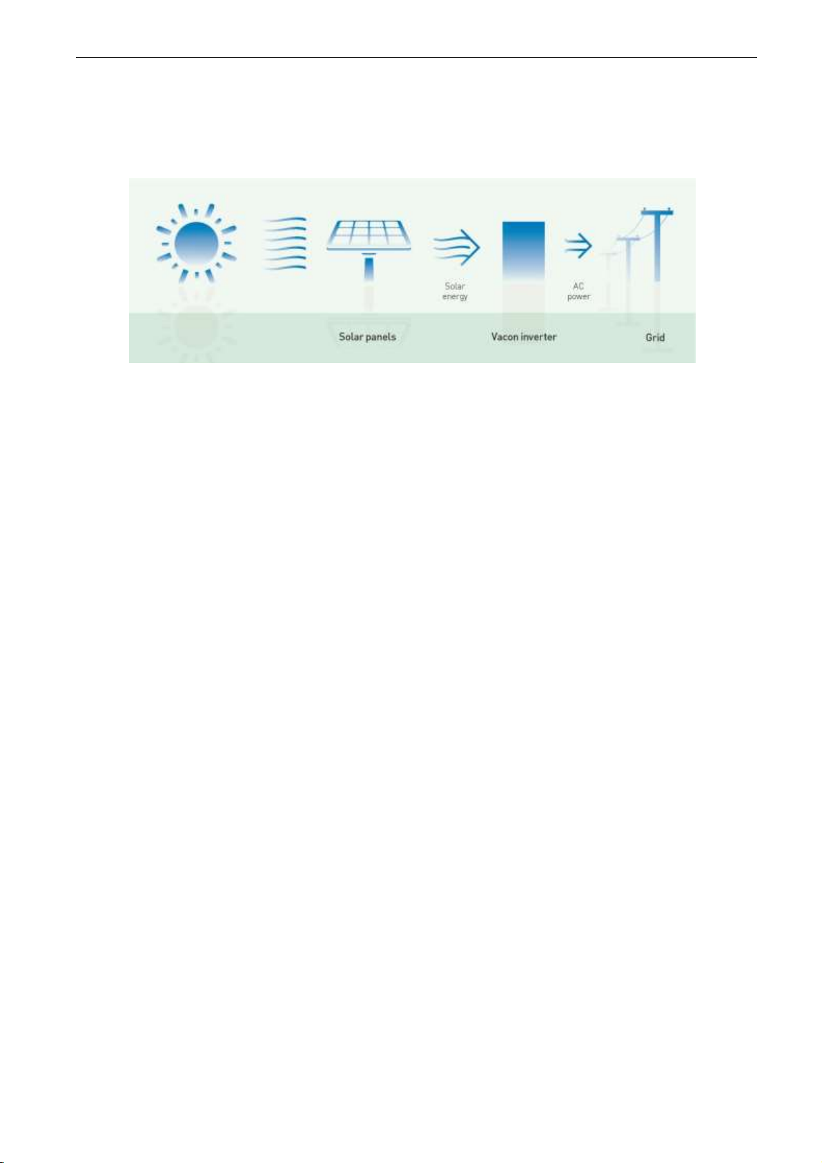
2. GENERAL
The power generation application is an answer to growing renewable energy market. The inverters
need only DC voltage and the grid to start producing energy.
Picture 1. Basic solar system.
2.1 Basic features
The power generation application works with Multi master and Stand-alone configurations. It can be
used with thin film and polycrystal Solar panels. Multi master configured system is controlled by
external Touch panel.
Additional functions:
• Grid Code functionality.
• Possibility to send Power Limit also from Fieldbus
• Multi-Master functionality with daily master change.
• Maximum Power Point Tracking
• Possibility to set any parameter value through Fieldbus interface.
2.2 Stand Alone
There is only one inverter unit which is producing energy to the grid. This system is working alone and
there is no need to use any external control systems or backup systems.
Page 10
10 • VACON® arfiff08 power generation
Local contacts: http://drives.danfoss.com/danfoss-drives/local-contacts/
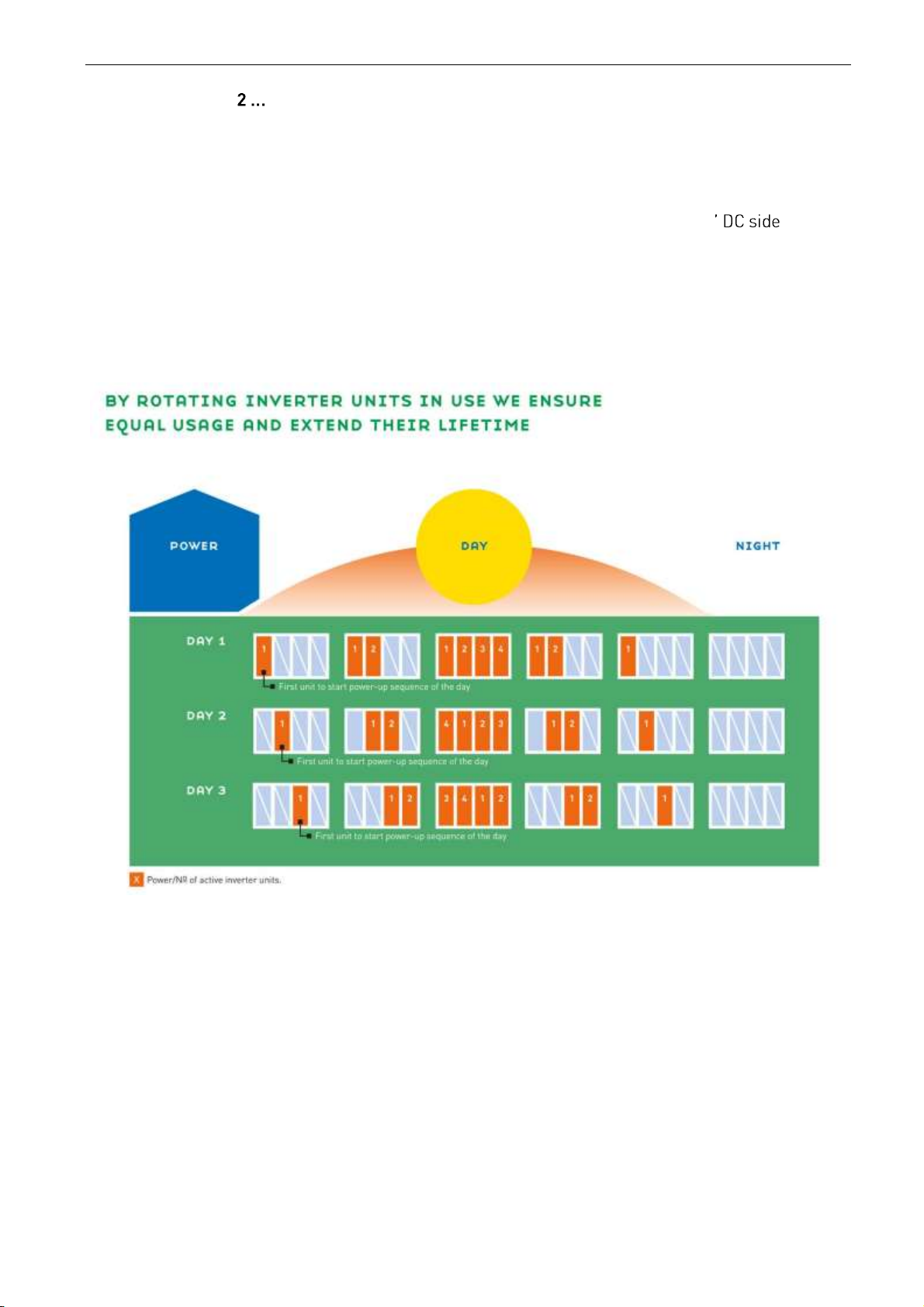
2.3 Multimaster ( 8 x inverter size)
The multi master functionality is used in bigger systems. There are two to eight inverter units which
are producing energy to the grid. This system has always the touch panel, which controls the system.
Inverters are equally loaded, because each time system is started, MPPT master is changed, which
will extend the lifetime of the inverters.
In the multi master system there is one inverter which is controlling other inverters behavior
and that inverter is called master inverter. Master inverter collects information of the DC bus and
makes decisions regarding what DC reference is used.
Other inverters are slave inverters and they follow DC reference coming from the master inverter.
Each of the inverters is responsible of its own behavior on the Grid side, i.e. complying with Grid Code
Standard.
Each unit is sending status information to operator panel and they can be read in touch panel.
Picture 2. Multi master system master change function.
Page 11
arfiff08 power generation VACON® • 11
Local contacts: http://drives.danfoss.com/danfoss-drives/local-contacts/
2.4 How to use
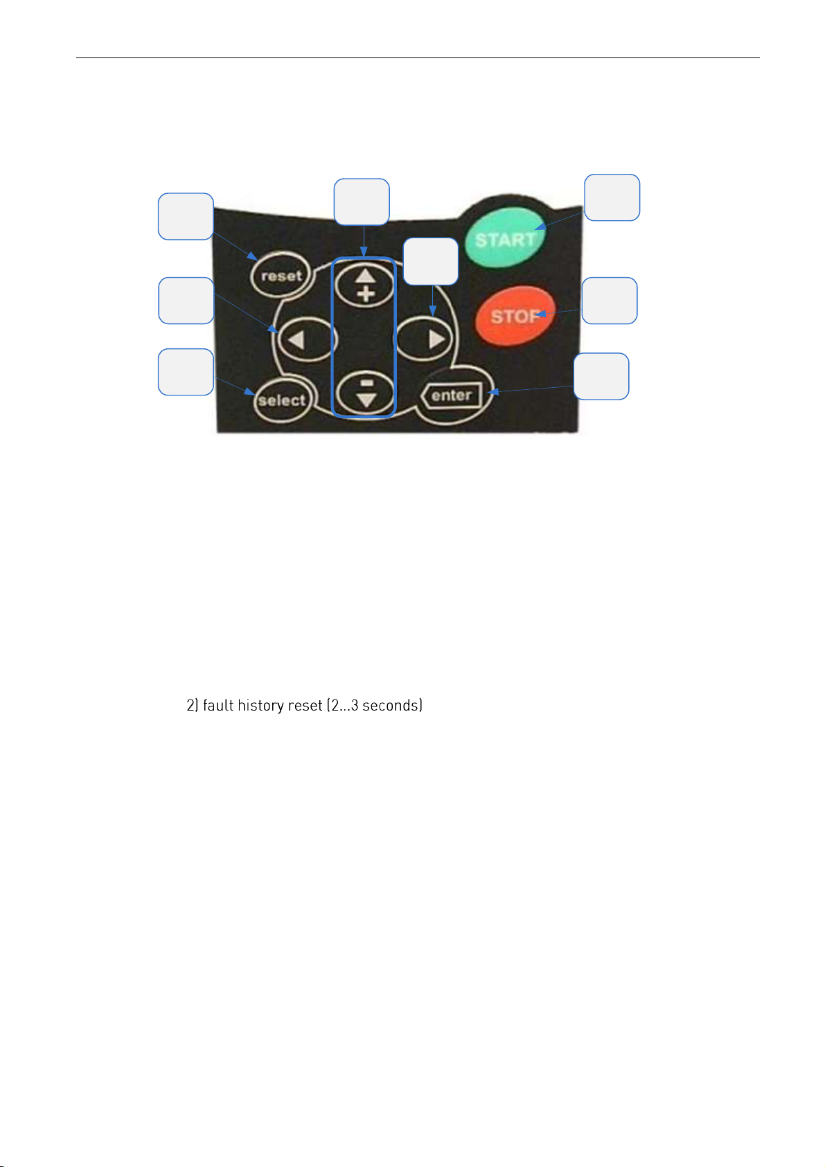
2.4.1
Keypad push buttons
1
1
2
3
4
5
6
7
8
Picture 3. Keypad push buttons
1 = Start button.
Pressing this button unit goes to ready state in multi master system or if standalone configuration is used it goes to ready state and if there is enough DC voltage, it
will try to run.
Pressing start button for 5 seconds when the Control Source is set to Panel forces
the drive to start regardless of DC level.
2 = Stop button.
Pressing this button stops the unit
3 = Enter button serves for:
1) confirmation of selections
4 = Select button is used to switch between two latest displays. May be useful when you
want to see how the changed new value influences some other value.
5 = Reset button is used to reset active faults.
6 = Browser button up and down
Browse the main menu and the pages of different submenus.
Edit values.
7 = Menu button left
Move backward in menu.
Move cursor left (in parameter menu).
Exit edit mode.
8 = Menu button right
Move forward in menu.
Move cursor right (in parameter menu).
Enter edit mode.
Page 12
12 • VACON® arfiff08 power generation
Local contacts: http://drives.danfoss.com/danfoss-drives/local-contacts/
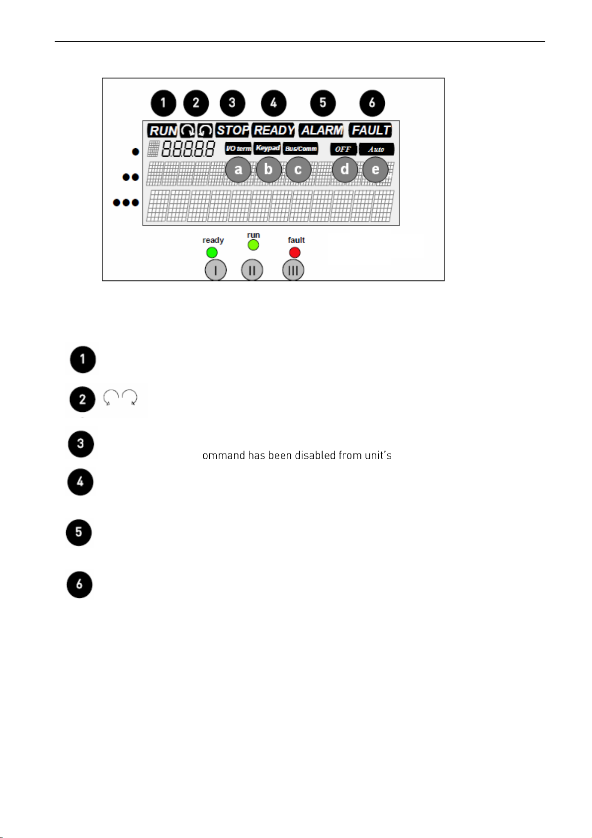
2.4.2
Inverter status indications
Picture 4.Keypad Indicators
The inverter status indications tell the user what the status of the Inverter and the Inverter is and
whether the Inverter control software has detected irregularities in Inverter functions.
RUN = Inverter is running;
= Indicates the direction of current flow.
STOP = Start c control panel.
READY = Lights when AC and DC Voltage is on. In case of a trip or stop button is pushed,
the symbol will not light up.
ALARM = Indicates that the Inverter is running outside a certain limit and a warning is
given.
FAULT = Indicates that unsafe operating conditions were encountered due to which the
Inverter was stopped.
Page 13
arfiff08 power generation VACON® • 13
Local contacts: http://drives.danfoss.com/danfoss-drives/local-contacts/
2.4.3
Control place indications
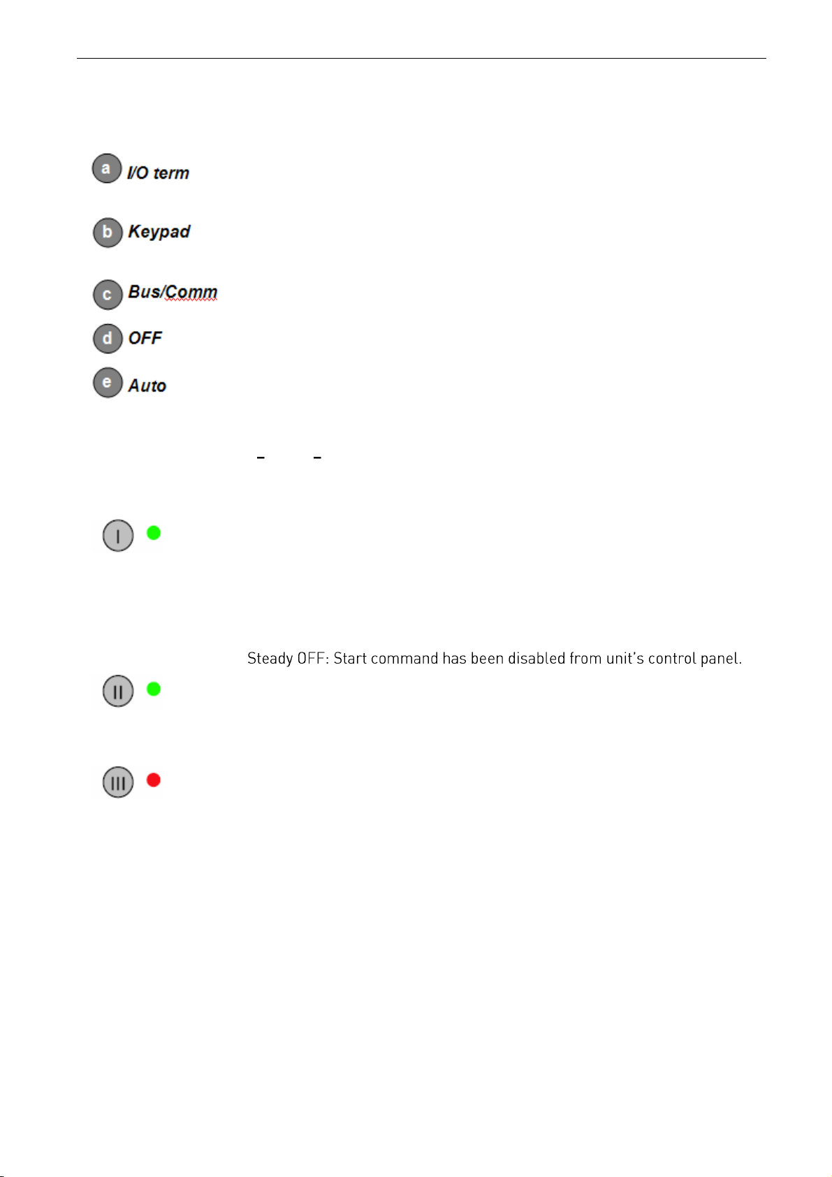
The symbols I/O term, Keypad and Bus/Comm (see Figure 7-1) indicate the choice of control place
made in the Keypad control menu (M3).
= I/O terminals are the selected control place; i.e. START/STOP commands or
reference values etc. are given through the I/O terminals.
= Control keypad is the selected control place; i.e. the Inverter can be started or
stopped, or its reference values etc. altered from the keypad.
= The inverter is controlled through a fieldbus.
= Run enable not active
= Unit is ready to start in the morning.
2.4.4
Status LEDs (green green red)
The status LEDs light up in connection with the READY, RUN and FAULT Inverter status
indicators.
(Ready) = Steady ON (no other LEDs): Start command has been given, all start criterions
have been fulfilled except that the drive has not detected high enough voltage
to start up.
Blinking at 2 Hz: All external start criterions have been fulfilled but no start
command has been given.
(Run) = Steady ON: The Inverter is running.
Blinking: Stop command has been given and the inverter is ramping power
down.
(Fault) = Blinks when unsafe operating conditions were encountered due to which the
Inverter was stopped (Fault Trip). Simultaneously, the Inverter status
indicator FAULT blinks on the display and the fault description can be seen
on the panel.
Page 14

14 • VACON® arfiff08 power generation
Local contacts: http://drives.danfoss.com/danfoss-drives/local-contacts/
2.4.5
Text lines
menu structure as well as with information related to the operation of the Inverter.
Location indication; displays the symbol and number of menu, parameter etc.
Description line; Displays the description of menu, value or fault.
Value line; Displays the numerical and textual values of references,
parameters etc. and the number of submenus available in each menu.
Page 15
arfiff08 power generation VACON® • 15
Local contacts: http://drives.danfoss.com/danfoss-drives/local-contacts/
3. APPLICATION
3.1 Quick Application Commissioning Guide
The Power generation application has been design for easy and fast commissioning. The user only
needs to set the Basic parameters and check if the there are any I/O parameters to be changed.
The Basic parameters are meant to be set in numerical order. Then the option board parameters are
set correctly automatically and system is ready faster.
3.1.1
Commissioning Steps
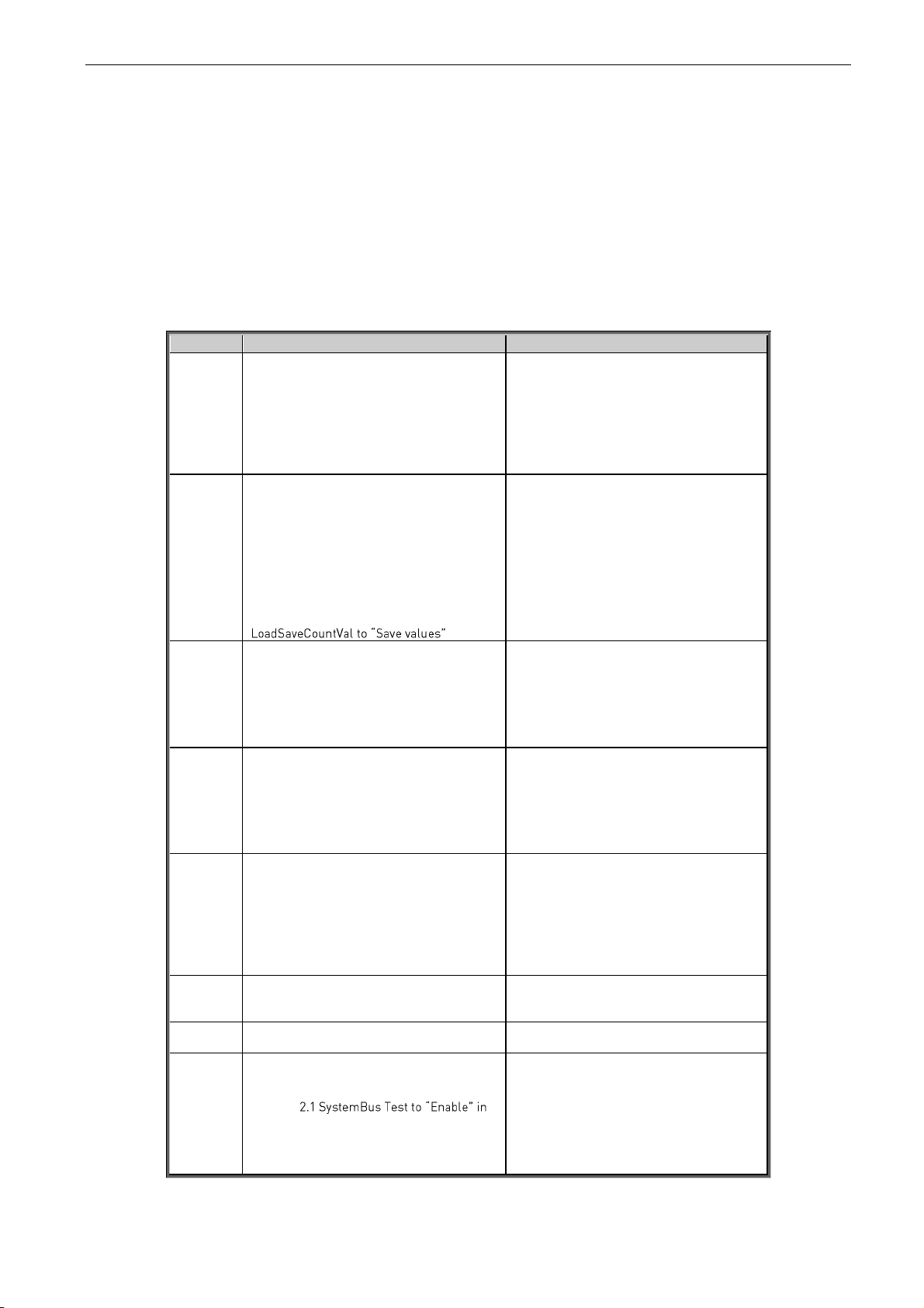
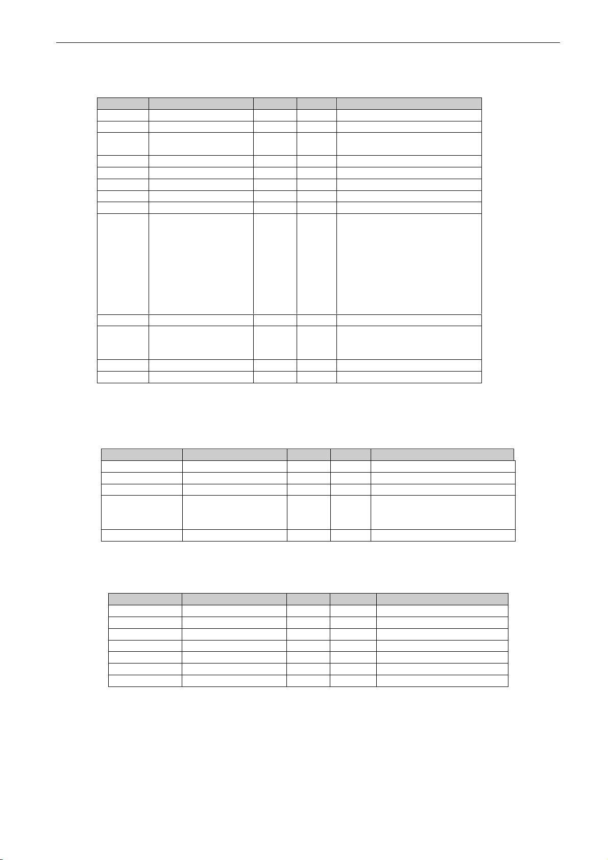
Table 1. Application Commissioning Steps
Step #
Step
Description
1
If you are updating the application to newer
version, write down the following counter
values before updating:
V1.1.10 Total Energy kWh
V1.1.13 RunTime Total
V1.1.16 Grid Connections
V1.1.17 IntFanRunHours
V1.1.18 ExtFanRunHours
These values need to be written down so
that the counters can be reset to correct
values after application update.
2
After application update, write the
corresponding counter values to these
parameters:
P2.10.2 TotalEnergyPreset
P2.10.3 GridConnPreset
P2.10.4 TotalRunTimPrese
P2.10.5 IntFanRuntPresVa
P2.10.6 ExtFanRuntPresVa
Change parameter P2.10.1
This will set the counters to the values
before application update.
3
Define right grid settings
P2.1.1 Grid Nom Voltage
P2.1.2 Grid Nom Freq
P2.1.6 Transf inv. side
P2.1.7 Transf grid side
When grid settings are right drive voltage is
calculated correct.
4
Set parameters P2.1.7 and P2.1.8 in
numerical order.
By setting the parameters in numerical
order the necessary option board
parameters are set also automatically to
their correct/default values.
This speeds up the process especially in
Multimaster system commissioning.
5
If commissioning is done before large scale
power production is possible, set P2.1.9.1
DC Start Level parameter to a level where
the inverter will surely start when the sun is
up.
Otherwise no need to change anything else
in Basic Parameters
This parameter indicates the minimum DC
voltage needed for the drive to try start up. If
this is larger than the current DC level when
the drive is stopped (as it is during morning
or evening commissioning) the drive will not
start.
6
Set the I/O parameters in G2.3 as required.
Some fault or warning may have been
triggered due to wiring in customized
cabinet solutions.
7
Reset any possible faults.
Reset the possible wiring related faults /
warnings.
8
Set P2.9.
any one unit
This will start a SystemBus test procedure
that will blink the Ready, Run and Fault
LEDs in all of the drives in order, starting
from the inverter where the parameter was
set.
If the LEDs do not blink in all of the units,
check the optical cables, jumper settings in
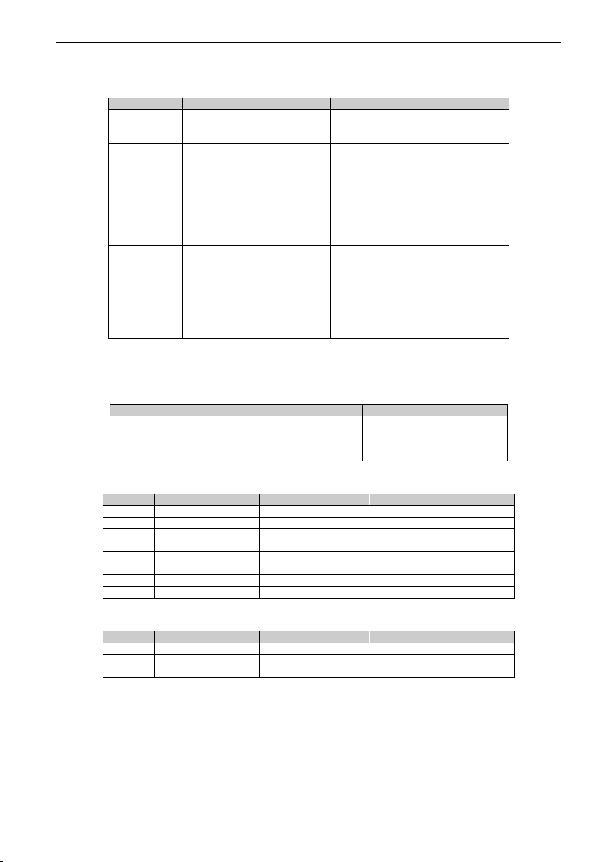
Page 16

16 • VACON® arfiff08 power generation
Local contacts: http://drives.danfoss.com/danfoss-drives/local-contacts/
OPT-D2 option boards and Basic parameters
in all of the drives.
9
Set P2.9.1.1 Simulation Mode to
and press start
in the Beijer panel
This activates the simulation mode where
drives use simulated DC voltage (P2.5.1.6)
and simulates power production which the
Beijer touch panel can see.
This test ensures that the system works as a
whole and the communication between the
inverters and Beijer touch panel is working
(in multimaster system) alright without
actually having DC or real output power.
You may need to lower the limit for starting
up the next follower in the Beijer
parameters to enable follower start ups.
10
When every drive in the system has ran,
press stop in the Beijer panel and set
P2.9
This disables the simulation mode and
enables the drive to run normally.
11
Give Start command.
If drive has not started but Ready LED is lit
and power production should be possible,
press Start button for 5 seconds.
If the DC is above the P2.1.9.1 DC Start Level
the drive will start. Pressing the Start button
for 5 seconds forces the drive to start
regardless of DC level.
12
Make sure parameter P2.1.9.6 DC Start
Level Max is set to appropriate value
compared to the specified open circuit
voltage of the panel field.
NOTE: during hot summer days, the actual
open circuit voltage can go as low as 90% of
the specified OC voltage, set the parameter
accordingly!
P2.1.9.6 DC Start Level Max is the absolute
maximum value that the addition of offset
after natural stops will not exceed. This is to
ensure that the start level never rises so
high that the drive will never start up.
13
In Multimaster system when power
production is ~75 % from system maximum,
use P2.2.2 DC Calibration to tweak the
output power of all of the drives to match
each other.
This is done to ensure that the small DC
voltage measurement errors between the
drives are not causing adverse effects on the
power production and the produced power
values are close to the same in the
Multimaster panel.
Page 17
arfiff08 power generation VACON® • 17
Local contacts: http://drives.danfoss.com/danfoss-drives/local-contacts/
3.1.2
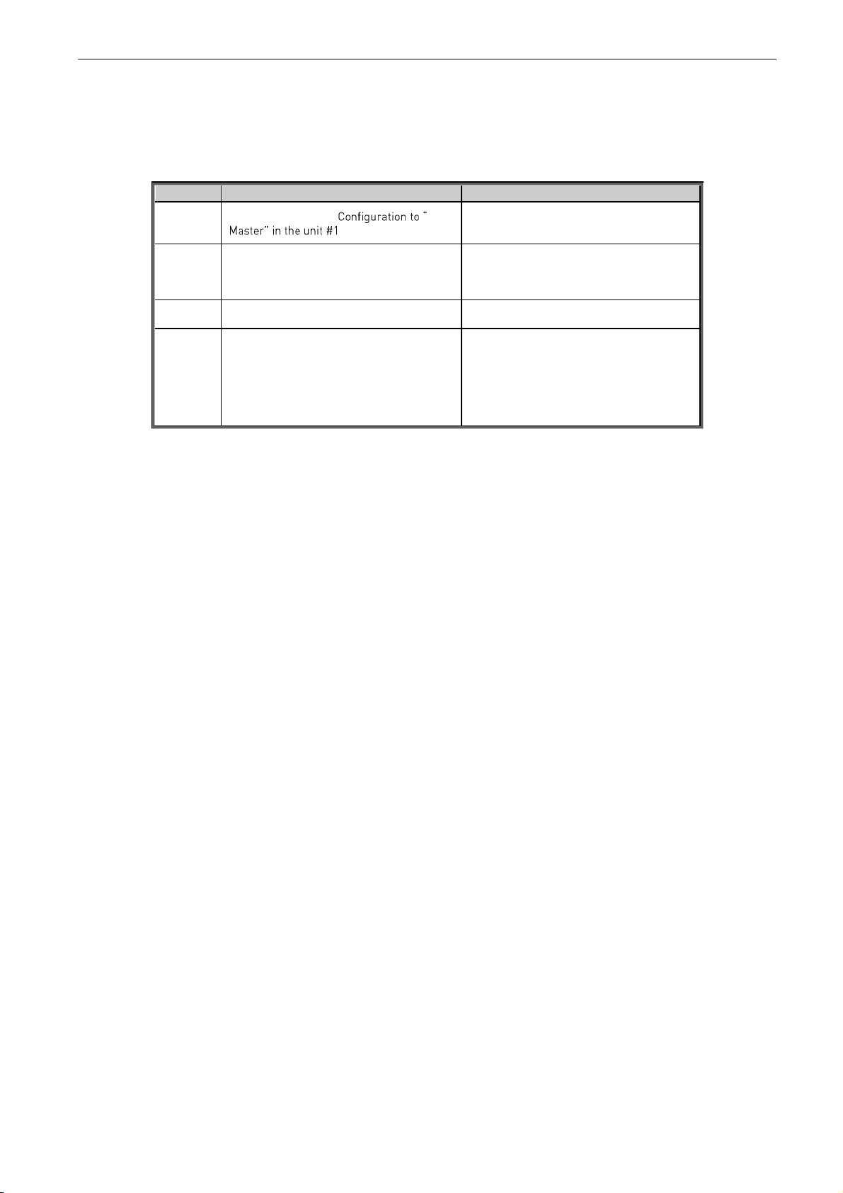
Multimaster PLC out of commission
If it happens that the multimaster control PLC is out of order, the drives are able to work using
master-follower operation mode where all of the drives are always working at the same time:
Step #
Step
Description
1
Set parameter P2.1.8 SB
This setting indicates for the unit #1 that it
needs to send the start command to the
other drives via SystemBus
2
Set P3.1 Control Source in the master to
Panel
This way the user can use the Panel to give
the Start command to the master unit and
the drive no longer listens to commands
from Fieldbus
3
Set P3.1 Control Source in all of the other
drives to SystemBus
This way the follower drives listen for the
Start command from SystemBus
4
Reset possible faults and give Start
command to the master unit.
If drives have not started but Ready LED is lit
in the Master unit and large scale power
production is possible, press Start button for
5 seconds.
The drives start up and start producing
power.
Page 18
18 • VACON® arfiff08 power generation
Local contacts: http://drives.danfoss.com/danfoss-drives/local-contacts/
4. MONITORING SIGNALS
The monitoring values are the actual values of parameters and signals as well as statuses and
measurements.
On the next pages you will find the lists of monitoring values within the respective monitor values
groups. The monitor values descriptions are given on pages 16 to 25.
Column explanations:
Code = Location indication on the keypad; Shows the operator the present parameter number
Values = Name of monitor value
Unit = Unit of monitor value; Given if available
ID = ID number of the parameter
All monitoring value is possible to monitoring from fieldbus by ID number
4.1 Basic monitor values
4.1.1
Monitoring values 1
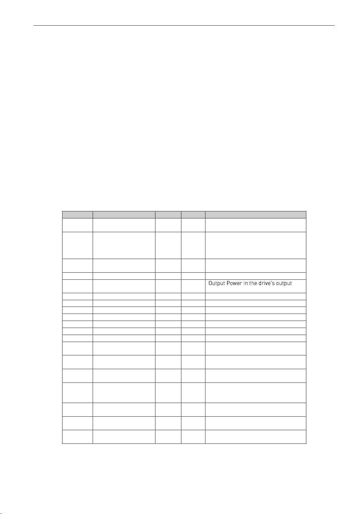
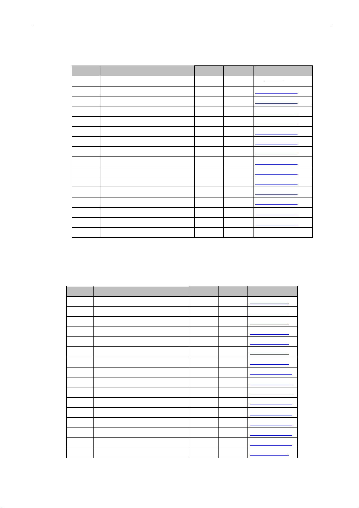
Table 2. Monitoring values 1
Code
Values
Unit
ID
Description
V1.1.1
DC-Link Voltage
V
1108
Measured DC Link voltage in volts,
filtered.
V1.1.2
DC Voltage Ref.
%
1200
Used DC voltage reference by the
regenerative unit in % of Nominal DC
voltage. Nominal DC voltage = 1.35 *
supply voltage
V1.1.3
Output Current
A
1834
Output current of the inverter coming
out of the cabinet.
V1.1.4
Reactive Current
%
1157
V1.1.5
Power kW
kW
1707
terminals.
V1.1.6
Supply Frequency
Hz
1123
Drive output frequency
V1.1.7
Supply Voltage
V
1107
Drive output voltage
V1.1.8
Grid Frequency
Hz
1835
Measured line frequency
V1.1.9
Grid Voltage
V
1709
Measured line voltage
V1.1.10
Total Energy kWh
kWh
1837
Total energy produced.
V1.1.11
Energy Today kWh
kWh
1708
Energy produced today.
V.1.1.12
Energy Yesterday
kWh
1733
Energy produced yesterday.
V1.1.13
Run Time Total
h
1836
Total time the inverter has been
running.
V1.1.14
RunTime Today
h
1731
The time the inverter has been
running today.
V.1.1.15
RunTimeYesterday
h
1732
The time the inverter was running
yesterday.
V1.1.16
Grid Connections
1706
Total number of times the inverter has
closed the main contactor and
connected to the grid.
V1.1.17
Int Fan Run Hours
h
1511
Total time internal fan has been
running
V1.1.18
Ext Fan Run Hours
h
1512
Total time external fan has been
running
V1.1.19
StandbyRemaining
s
1201
Remaining time in standby mode, if
standby mode is activated.
Page 19
arfiff08 power generation VACON® • 19
Local contacts: http://drives.danfoss.com/danfoss-drives/local-contacts/
4.1.2
Monitoring values 2
Table 3. Monitoring values 2
Code
Values
Unit
ID
Description
V1.2.1
Cos Phii Actual
1717 V1.2.2
Unit Temperature
°C
1109
V1.2.3
Reactive Current
Reference
%
1389
V1.2.4
Active Current
%
1125
V1.2.5
InverterStatus 1
1819
Diagnostic statusword 1
V1.2.6
InverterStatus 2
1820
Diagnostic statusword 2
V1.2.7
InverterStatus 3
1821
Diagnostic statusword 3
V1.2.8
InverterStatus 4
1822
Diagnostic statusword 4
V1.2.9
EEPROMSaveStatus
1106
Status of the nonvolatile
memory (EEPROM) storing
activated by the application
0 = IDLE
1 = ACTIVE
2 = RESOURCE ERROR
3 = WRITE ERROR
4 = NOT FOUND
5 = NOT SUPPORTED (e.g. NXP2)
V1.2.10
Status Word
43
V1.2.11
Used DC start level
V
1965
Monitoring Value for the
currently used DC Start Level
value.
V1.2.12
Mindex
%
1874
Modulation Index
V1.2.13
Calibrated DC Voltage
V
1839
4.1.3
Fieldbus monitoring values
Table 4. Fieldbus
Code
Values
Unit
ID
Description
V1.3.1
FB Control Word
1478
Control word from fieldbus
V1.3.2
FB Status Word
1479
Status word to fieldbus
V1.3.3
FB GenPowerLim
1481
Power limit sent by the fieldbus
V1.3.4
FB Q/PF Ref
Q: %
PF: -
1480
Reactive Current or Power
Factor reference sent by the
fieldbus
V1.3.5
Day from PLC
1719
Day index sent from the PLC
4.1.4
I/O monitoring values
Table 5. I/O Monitor
Code
Values
Unit
ID
Description
V1.4.1
DIN1, DIN2, DIN3
15
V1.4.2
DIN4, DIN5, DIN6
16
V1.4.3
DIN Status 1
56
V1.4.4
DIN Status 2
57
V1.4.5
Analogue Input 1
%
13
V1.4.6
Analogue Input 2
%
14
V1.4.7
Custom AnOut 1
%
1240
Page 20
20 • VACON® arfiff08 power generation
Local contacts: http://drives.danfoss.com/danfoss-drives/local-contacts/
4.1.5
MPPT
Table 6. MPPT
Code
Values
Unit
ID
Description
V1.5.1
MPPT Reference
1816
The DC reference from the
MPP tracker. Shows without
ramping if ramping is used.
V1.5.2
Actual Step Size
1815
This value shows the actual
momentary step size of the
MPP tracker.
V1.5.3
Actual Step Ratio
1825
This value shows the actual
step ratio. Power change
divided by actual step size.
The value is used for
evaluating the size of the next
step.
V1.5.4
Actual Step State
1817
State of the MPP tracker.
For debugging purpose only.
V1.5.5
Power Window On
0
Power window status.
V1.5.6
Optimal DC Point
1724
Estimated optimal DC Point
is the DC Reference point
which giving the best
simulated power.
4.1.6
License key activation
Table 7. License key activation
Code
Values
Unit
ID
Description
V1.6.1
Serial Number Key
1997
Give this number to the
technical support of the
manufacturer in case of licence
key problems.
4.1.7
Grid code
Code
Parameter
Unit
Form.
ID
Description
V1.7.1
Line State
# 2202
V1.7.2
Line Voltage GC
%
#,##
1912
Line Voltage used by Grid Code
V1.7.3
Line Frequency GC
%
#,##
1913
Line Frequency used by Grid
Code
V1.7.4
Line Voltage L1-L2
%
#,##
2203 V1.7.5
Line Voltage L2-L3
%
#,##
2204 V1.7.6
Line Voltage L3-L1
%
#,##
2205 V1.7.7
Trip State
2206
4.1.8
PID Controller
Code
Parameter
Unit
Form.
ID
Description
V1.8.1
PID Reference
#,#
20 V1.8.2
PID Actual Value
#,#
21 V1.8.3
PID Output
#,##
23
Page 21
arfiff08 power generation VACON® • 21
Local contacts: http://drives.danfoss.com/danfoss-drives/local-contacts/
4.2 Monitor Values descriptions
4.2.1
Monitoring values 1
V1.1 DC -link Voltage V ID 1108
Filtered DC Link voltage in Volts.
V1.2 DC Voltage Reference % ID 1200
Used DC voltage reference. 100 % = 1,35 x Nominal AC Voltage.
V1.3 Output Current A ID 1834
Output current of the inverter coming out of the cabinet.
V1.4 Reactive Current % ID 1157
The reactive current of the regenerative drive in % of System Rated Current.
V1.5 Output Power kW ID 1707
V1.6 Supply Frequency Hz ID 1123
The drive output frequency.
V1.7 Supply Voltage V ID 1107
The drive output voltage.
V1.8 Grid Frequency Hz ID 1835
Grid frequency in ##.## Hz. The sign indicates the phase order. Can be monitored only
when UNIT is in RUN state.
V1.9 Grid Voltage V ID 1709
AC Voltage measured on the grid side of the main contactor by an external measurement
circuit.
V1.10 Total Energy kWh kWh ID 1837
Total produced energy to the grid
V1.11 Energy Today kWh kWh ID 1708
Amount of energy produced today.
Page 22

22 • VACON® arfiff08 power generation
Local contacts: http://drives.danfoss.com/danfoss-drives/local-contacts/
V1.12 Energy Yesterday kWh ID 1733
Amount of energy produced yesterday.
V1.13 Run Time Total h ID 1836
Total time the inverter has been running.
V1.14 Run Time Today h ID 1731
The time the inverter has been running today.
V1.15 Run Time Yesterday h ID 1732
The time the inverter was running yesterday.
V1.16 Grid Connections ID 1706
Total number of times the inverter has closed the main contactor and connected to the
grid.
V1.17 Int Fan Run Hours h ID 1511
Total time internal fan has been running
V1.18 Ext Fan Run Hours h ID 1512
Total time external fan has been running
V1.19 Standby Remaining s ID 1201
Remaining time in standby mode, if standby mode is activated.
Page 23

arfiff08 power generation VACON® • 23
Local contacts: http://drives.danfoss.com/danfoss-drives/local-contacts/
4.2.2
Monitoring values 2
V1.2.1 CosPhiiActual ID 1717
The calculated Cos Phi.
V1.2.2 Unit Temperature °C ID 1109
The heatsink temperature of the drive.
V1.2.3 Reactive Current Reference % ID1389
The final reactive current reference.
V1.2.4 Active Current % ID 1125
The active current in % of System Rated Current.
A negative value means that the current is flowing to AC side from DC side.
Page 24
24 • VACON® arfiff08 power generation
Local contacts: http://drives.danfoss.com/danfoss-drives/local-contacts/
V1.2.5 Inverter statusword 1 ID 1819
Diagnostic statusword 1.
Bit
Name
Value = 0
Value = 1
Description
0
Main Switch Open Fault
No Fault
Fault
See Fault list 64
1
Main Switch Open Warning
No Alarm
Alarm
See Fault list 64
2
AC Voltage Max Fault
No Fault
Fault
See Fault list 72
3
AC Voltage Min Fault
No Fault
Fault
See Fault list 73
4
AC Freg Max Fault
No Fault
Fault
See Fault list 74
5
AC Freg Min Fault
No Fault
Fault
See Fault list 75
6
DC Ground Warning
No Alarm
Alarm
See Fault list 76
7
DC Ground Fault
No Fault
Fault
See Fault list 77
8
Surge Alarm
No Alarm
Alarm
See Fault list 83
9
FB Heardbeat timeout
No Fault
Fault
See Fault list 85
10
Input Switch Alarm
No Alarm
Alarm
See Fault list 86
11
Emergency Switch
No Fault
Fault
See Fault list 87
12
UnBalance
No Alarm
Alarm
See Fault list 18
13
Thermistor Fault
No Fault
Fault
See Fault list 29
14
Safe Disable
No Fault
Fault
See Fault list 30
15
Reserved
No Fault
Fault
V1.2.6 Inverter statusword 2 ID 1820
Diagnostic statusword 2.
Bit
Name
Value = 0
Value = 1
Description
0
Overvoltage
No Fault
Fault
See Fault list 2
1
Earth Fault
No Fault
Fault
See Fault list 3
2
Inverter Fault
No Fault
Fault
See Fault list 4
3
Charge Switch Fault
No Fault
Fault
See Fault list 5
4
Saturation
No Fault
Fault
See Fault list 7
5
Unknown Fault
No Fault
Fault
See Fault list 8
6
Undervoltage
No Fault
Fault
See Fault list 9
7
Input Phase Fault
No Fault
Fault
See Fault list 10
8
Input Phase Warning
No Alarm
Alarm
See Fault list 10
9
Supply Phase Loss
No Fault
Fault
See Fault list 11
10
Supply Phase Warning
No Alarm
Alarm
See Fault list 11
11
Over Temperature
No Fault
Fault
See Fault list 14
12
Over Temperature Warning
No Alarm
Alarm
See Fault list 14
13
Undertemp
No Fault
Fault
See Fault list 13
14
Temperature Power limit warning
No Alarm
Alarm
See Fault list 97
15
OverCurrent
No Fault
Fault
See Fault list 1
Page 25
arfiff08 power generation VACON® • 25
Local contacts: http://drives.danfoss.com/danfoss-drives/local-contacts/
V1.2.7 Inverter statusword 3 ID 1821
Diagnostic statusword 3.
V1.2.8 Inverter statusword 4 ID 1822
Diagnostic statusword 4.
Bit
Name
Value = 0
Value = 1
Description
0
Processor Watchdog
No Fault
Fault
See Fault list 25
1
Reserved
2 IGBT HW Temp
No Fault
Fault
See Fault list 31
3
Cooling Fan
No Fault
Fault
See Fault list 32
4
Application Fault
No Fault
Fault
See Fault list 35
5
Control Unit Fault
No Fault
Fault
See Fault list 36
6
Device Changed
No Fault
Fault
See Fault list 37
7
Device Added
No Fault
Fault
See Fault list 38
8
Device Moved
No Fault
Fault
See Fault list 39
9
Device Unknown
No Fault
Fault
See Fault list 40
10
Device Changed
No Fault
Fault
See Fault list 44
11
Device Added
No Fault
Fault
See Fault list 45
12
EEprom Checksum fault
No Fault
Fault
See Fault list 22
13
Counter Fault
No Fault
Fault
See Fault list 24
14
Reserved
No Fault
Fault 15
Reserved
No Fault
Fault
Bit
Name
Value = 0
Value = 1
Description
0
IGBT Temperature
No Fault
Fault
See Fault list 41
1
EEPROM Fault
No Fault
Fault
See Fault list 48
2
Zero Divice Fault
No Fault
Fault
See Fault list 49
3
External Fault Active
No Fault
Fault
See Fault list 51
4
External Warning Active
No Alarm
Alarm
See Fault list 51
5
Reserved
6 Fieldbus Communication
No Fault
Fault
See Fault list 53
7
Slot Communication
No Fault
Fault
See Fault list 54
8
System bus Master Heartbeat Trip active
No Fault
Fault
See Fault list 59
9
System bus Communication Fault Trip
Active
No Fault
Fault
See Fault list 55
10
LCL OverTemp Fault Active
No Fault
Fault
See Fault list 70
11
LCL OverTemp Warning Active
No Alarm
Alarm
See Fault list 70
12
User Temp Alarm
No Alarm
Alarm
Fault code 99
13
Analog Signal Too Low Fault active
No Fault
Fault
Fault code 50
14
Analog Signal Too Low Warning active
No Alarm
Alarm
Fault code 50
15
Reserved
Page 26
26 • VACON® arfiff08 power generation
Local contacts: http://drives.danfoss.com/danfoss-drives/local-contacts/
V1.2.9 EEPROM Saving Status ID 1106
Status of the nonvolatile memory (EEPROM) storing activated by the application
0 = IDLE
1 = ACTIVE
2 = RESOURCE ERROR
3 = WRITE ERROR
4 = NOT FOUND
5 = NOT SUPPORTED (e.g. NXP2)
V1.2.10 Status Word ID 43
Application Status Word combines different drive statuses to one data word.
Application Status Word ID43
FALSE
TRUE
b0
b1
Not in Ready state
Ready
b2
Not Running
Running
b3
No Fault
Fault
b4
b5
b6
Run Disabled
Run Enable
b7
No Warning
Warning
b8 Charging Switch closed (internal)
b9 MCB Control (DO Final)
b10 MCB Feedback
b11 DO Charging Active
b12
No Run Request
Run Request
b13
b14 PV Field OK
b15
V2.1.2.11 Used DC start level ID 1965
Monitoring Value for the currently used DC Start Level value.
V2.1.2.12 Mindex ID 1874
This value can be used to recognize low Dc-Link voltage when operating in island mode.
If the value is above 90%, the drive is in limits to make correct voltage to the AC side.
V2.1.2.13 Calibrated DC Voltage ID 1839
Calibrated DC Voltage is used in the parallel drives
Page 27
arfiff08 power generation VACON® • 27
Local contacts: http://drives.danfoss.com/danfoss-drives/local-contacts/
4.2.3
Fieldbus monitoring values
V1.3.1 FB Control Word ID 1478
Control Word received from the Fieldbus Master.
FB Control Word
Signal
Comment
b0
Start
0 = Stop Command
1 = Start Command
b1
b2
Reset
0>1 Reset fault.
b3
b4
b5
b6
b7
b8
Master
Master command
b9
b10
b11
b12
b13
ReactCurrOr
CosPhiiRefSel
0 = Reactive Current Control
1 = CosPhii Control
b14
FB Force start
0 = Normal Start
1 = Force Start regardless of DC voltage level
b15
Page 28
28 • VACON® arfiff08 power generation
Local contacts: http://drives.danfoss.com/danfoss-drives/local-contacts/
V1.3.2 FB Status Word ID 1479
Status Word sent to the upper system/PLC via Fieldbus.
FB Status Word
Signal
Comment
b0
StartCriterions
FullFilled
Not only if Inverter control is ready, but if all
b1
Inverter Activated
When active, the inverter can be in either in Standby or
Inverter Running mode.
b2
b3
Fault
b4
Warning
b5
Inverter Activated Standby
b6
b7
Main contactor close
command
b8
Master
Master command
b9
Pulse 1s
Heartbeat bit. The inverter toggles this bit on and off.
1s on, 1s off.
b10
ChargeSwState
0 = Open
1 = Closed
b11
b12
b13
b14
b15
V1.3.3 FB GenPowerLim ID 1481
Power limit sent by the fieldbus.
V1.3.4 FB Q/PF Ref ID 1480
Reactive Current or Power Factor Reference received from Fieldbus. Control Word
states which reverence is used.
V1.3.5 Day From PLC ID 1719
Day index sent from the PLC.
Page 29
arfiff08 power generation VACON® • 29
Local contacts: http://drives.danfoss.com/danfoss-drives/local-contacts/
4.2.4
I/O monitoring values
V1.4.1 DIN1, DIN2, DIN3 ID 15
V1.4.2 DIN4, DIN5, DIN6 ID 16
DIN1/DIN2/DIN3 status
DIN4/DIN5/DIN6 status
b0
DIN3
DIN6
b1
DIN2
DIN5
b2
DIN1
DIN4
V1.4.3 DIN Status 1 ID 56
V1.4.4 DIN Status 2 ID 57
DIN StatusWord 1
DIN StatusWord 2
b0
DIN: A.1
DIN: C.5
b1
DIN: A.2
DIN: C.6
b2
DIN: A.3
DIN: D.1
b3
DIN: A.4
DIN: D.2
b4
DIN: A.5
DIN: D.3
b5
DIN: A.6
DIN: D.4
b6
DIN: B.1
DIN: D.5
b7
DIN: B.2
DIN: D.6
b8
DIN: B.3
DIN: E.1
b9
DIN: B.4
DIN: E.2
b10
DIN: B.5
DIN: E.3
b11
DIN: B.6
DIN: E.4
b12
DIN: C.1
DIN: E.5
b13
DIN: C.2
DIN: E.6
b14
DIN: C.3
b15
DIN: C.4
V1.4.5 Analogue Input 1 % ID 13
V1.4.6 Analogue Input 2 % ID 14
V1.4.7 Custom AnOut 1 % ID 1240
Customized analogue output
Page 30
30 • VACON® arfiff08 power generation
Local contacts: http://drives.danfoss.com/danfoss-drives/local-contacts/
4.2.5
MPPT
V1.5.1 MPP Reference ID 1816
The DC reference of the MPP tracker.
V1.5.2 Actual Step Size ID 1815
This value shows the actual momentary step size of the MPP tracker.
V1.5.3 Actual Step Ratio ID 1825
This value shows the actual step ratio. Power change divided by actual step size. The
value is used for evaluating the size of the next step.
V1.5.4 MPPT State ID 1817
State of the MPP tracker. For debugging purposes only.
P1.5.5 Power Window On
When the MPP tracker takes a step in any direction, the power change has to be bigger
than the Power Window for making a decision if the Power has increased or decreased.
Otherwise it will take another step in the same direction until the limit is exceeded.
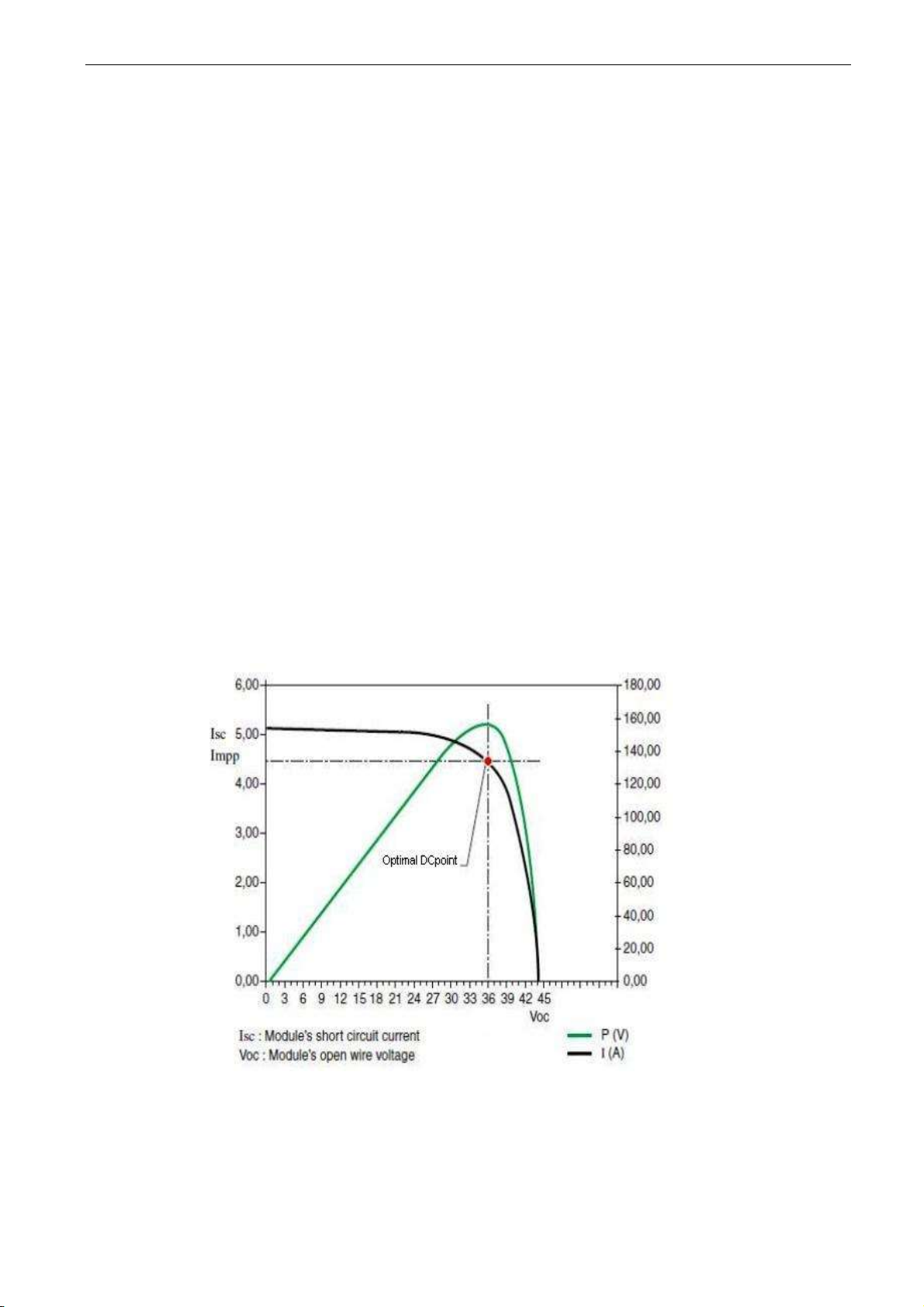
V1.5.6 Simulated Optimal DC point ID 1724
Estimated optimal DC Point is the DC Reference point which giving the best simulated
power.
Picture xx. Optimal DC point.
Page 31

arfiff08 power generation VACON® • 31
Local contacts: http://drives.danfoss.com/danfoss-drives/local-contacts/
4.2.6
License key activation
V1.6.1 Serial Number Key ID 1997
Give this number to the technical support of the manufacturer when there is a problem
in the activation of a function. The drive shows a licence fault.
4.2.7
Gird code
V1.7.1 Line State ID 2202
Give this number to the technical support of the manufacturer when there is a problem
in the activation of a function. The drive shows a licence fault.
Line State
Signal
b0
LineVoltageHighFast_Act
b1
LineVoltageHighSlow_Act
b2
LineVoltageLowSlow_Act
b3
LineVoltageLowFast_Act
b4
LineFreqHighFast_Act
b5
LineFreqHighSlow_Act
b6
LineFreqLowSlow_Act
b7
LineFreqLowFast_Act
b8
LVRTTimerStart
b9
LVRTBiTimerStart
b10
SeparateLimitOrForces
b11
LineFreqRate
b12
10minAverageTrip
b13
FALSE
b14
FALSE
b15
FALSE
V1.7.2 Line Voltage GC % #,## 1912
V1.7.3 Line Frequency GC % #,## 1913
V1.7.4 Line Voltage L1-L2 % #,## 2203
V1.7.5 Line Voltage L2-L3 % #,## 2204
V1.7.6 Line Voltage L3-L1 % #,## 2205
V1.7.7 Trip State 2206
Page 32

32 • VACON® arfiff08 power generation
Local contacts: http://drives.danfoss.com/danfoss-drives/local-contacts/
4.2.8
PID Controller
Monitoring values for power controller
V1.8.1 PID Reference ID 20
Active Current reference
V1.8.2 PID Actual Value ID 21
Active current
V1.8.3 PID Output ID 23
PID controller output for DC Voltage reference, gives an offset for DC Voltage Reference.
Page 33

arfiff08 power generation VACON® • 33
Local contacts: http://drives.danfoss.com/danfoss-drives/local-contacts/
5. PARAMETERS
On the next pages you will find the lists of parameters within the respective parameter groups. The
parameter descriptions are given in the chapter 6. Parameter description includes more than is
available in this application see parameter list what is available.
Column explanations:
Code = Location indication on the keypad; Shows the operator the present parameter number
Parameter = Name of parameter
Min = Minimum value of parameter
Max = Maximum value of parameter
Unit = Unit of parameter value; Given if available
Default = Value preset by factory
ID = ID number of the parameter
All parameters is possible to control from fieldbus by ID number
5.1 P2.1 Basic parameters
Table 9. Basic parameters
Code
Parameter
Min
Max
Unit
Default
ID
Description
P2.1.1
Grid Nom Voltage
200
1000
Vac
500V:400
690V:690
110
Set the nominal voltage of the
grid.
P2.1.2
Grid Nom Frequency
-320,00
320,00
Hz
50,00
1532
Initial start frequency
P2.1.3
Unit nom Current
0.0
Ih A Il
113
Used to scale % values.
P2.1.4
Parallel AFE
0 1 0 1501
0 = Single AFE
1 = Parallel AFE
P2.1.5
Transformer: Inverter
Side
0
3200
Vac
400
1850
P2.1.6
Transformer: Grid Side
0
3200
Vac
400
1851
P2.1.7
Number Of Units
0 8 1 1604
Number of units in array mode
system. Needed e.g. for system
bus communication
P2.1.8
Configuration
-1 9 0 1531
Sets the inverter in a standalone or panel/array mode. In
array mode the inverter has to
be given a unique inverter
number. Communication
parameters for touchpad panel
communication, systembus and
CAN communication are set
based on this value.
Page 34
34 • VACON® arfiff08 power generation
Local contacts: http://drives.danfoss.com/danfoss-drives/local-contacts/
5.1.1
DC Level Setup
Table 10. DC Level Setup
Code
Parameter
Min
Max
Unit
Default
ID
Description
P2.1.9.1
DC Start Lvl
0
2000 V 570
1962
If DC voltage is above this limit when the
drive is stopped, DC is considered to be
high enough to start-up.
If the the DC is below this level when the
drive is stopped, the DC is considered to
be too low to produce power and drive
will not try to start-up.
P2.1.9.2
DCStartLvlDelay
1,00
320,00 s 10,00
1964
Delay for when the DC rises above
P2.1.7.2 before DC level is considered
high enough for starting.
P2.1.9.3
DCStartLvlSource
0 1
1
1966
will always use the user-set value in
P2.1.7.1 as the Start Level
drive will use the open circuit DC voltage
from the previous natural stop + offset
from P2.1.7.5 as the new Start Level.
P2.1.9.4
DCStartLvlOffset
0
300 V 15
1967
Offset value to be used when P2.1.7.4 is
P2.1.9.5
DCStartMaxLimit
0
2000 V 590
1968
Absolute maximum value for the Strt/Stp
Level when P2.1.7.4 is set to
5.2 Reference Handling
Code
Parameter
Min
Max
Unit
Default
ID
Description
P2.2.1
Cos phi ref
-1,0
1,0 1,0
2304
Cos phi reference
P2.2.2
Reactive Current
Reference
-300
300 % 0
1459
Regenerative reactive
current reference 100.0 =
Nominal current.
Positive =Inductive
Negative = Capacitive
5.2.1
DC Reference
Code
Parameter
Min
Max
Unit
Default
ID
Description
P2.2.3.1
DC Drooping
0,00
100,00
%
0,00
620
DC Drooping for balancing
current output.
P2.2.3.2
DC Calibration
-5,00
5,00 % 0,00
1777
DC calibration for balancing
the outputs of parallel drives
P2.2.3.3
Manual DC
0 1 0 1808
0 = Disable
1 = Enable
P2.2.3.4
Manual DC Reference
0,00
320.00
%
150,00
1809
Reference for manual DC
control
Page 35

arfiff08 power generation VACON® • 35
Local contacts: http://drives.danfoss.com/danfoss-drives/local-contacts/
5.2.2
Power/frequency reference
Code
Parameter
Min
Max
Unit
Default
ID
Description
P2.2.4.1
Gen Power Ref.
0
170.0 % 0.0
1533
P2.2.4.2
ReferenceMode
0 1 0 1914
0 = Pure Iq ref
1 = Volt comp Iq
5.2.2.1 PID Power Controller
Code
Parameter
Min
Max
Unit
Default
ID
Description
2.2.4.3.1
PID Power Activation
0.1
W.10
DigIN
0.1
1907
2.2.4.3.2
PID Kp
0,00
1e6 % 100,00
1911 2.2.4.3.3
PID Ti
0
1e5
ms
1000
1906 2.2.4.3.4
PID DC Low
-50,00
50,00 % -5,00
1903 2.2.4.3.5
PID DC High
-50,00
50,00 % 5,00
1904
2.2.4.3.6
Reference Down Rate
-1,00
100
%/s
-1,00
1842
2.2.4.3.7
Reference Up Rate
-1,00
100
%/s
-1,00
1843
5.2.3
AC Voltage reference
Code
Parameter
Min
Max
Unit
Default
ID
Description
P2.2.5.1
Capacitor Size
0,0
100,0 % 5,4
1460
Regen filter capacitor size in
###.# %
P2.2.5.2
Inductor Size
0,0
100,0 % 3,0
1461
Regen total filter inductance in
###.# %
P2.2.5.3
Capacitor Size 2nd
0,0
100,0 % 0,0
3330
P2.2.5.4
Capacitor Size 2nd
Voltage
0,0
1100,0
%
0,0
3331
Page 36

36 • VACON® arfiff08 power generation
Local contacts: http://drives.danfoss.com/danfoss-drives/local-contacts/
5.3 IO Signals
5.3.1
Digital Inputs
Note! Check also G2.3.1.13 Configuration parameters for inverted inputs!
Note! If Digital Input signal source is set to DigIn:F.1 or DigIn:F.2, ANIN as
DIGIN1 ANIN as DIGIN2 respectively as signal source.
Note! To disable certain function, set the signal source to DigIN:0.1 (always FALSE) or DigIN:0.2
(always TRUE).
Table 12. Digital Input parameters
Code
Parameter
Min
Max
Default
ID
Description
P2.3.1.1
External Trip
DigIN:0.1
DigIN:F.10
DigIN:0.1
1214
Select the digital input to
activate External Trip.
P2.3.1.2
Surge Alarm
DigIN:0.1
DigIN:F.10
DigIN:0.1
1806
Select the digital input to
Activate Surge Alarm.
P2.3.1.3
Main Cont Ack
DigIN:0.1
DigIN:F.10
DigIN:0.1
1453
This parameter defines if the
inverter monitors the status of
the main contactor of the unit.
If the monitoring function is
used, the unit monitors the
status and will not start if the
state of the contactor does not
correspond to the required
status, i.e. is open when it
should be closed.
If status of the main contactor
is not monitored in the system
the option DigIN:0.x must be
chosen.
P2.3.1.4
Fault Reset
DigIN:0.1
DigIN:F.10
DigIN:0.1
1208
Select digital input used for
fault reset.
P2.3.1.5
DCSwitchFeedback
DigIN:0.1
DigIN:F.10
DigIN:0.2
1212
This parameter defines which
digital input is used for DC
Switch Feedback signal. If this
is used the inverter will not go
to ready state unless the
DCSwitchFeedback signal is
TRUE.
P2.3.1.6
FilterOverTemp
DigIN:0.1
DigIN:F.10
DigIN:0.1
1179
Digital input for trigging a LCL
filter over temperature fault.
P2.3.1.7
DC Insulation
DigIN:0.1
DigIN:F.10
DigIN:0.1
1180
Digital input for trigging DC
Insulation.
P2.3.1.8
Emergency Switch
DigIN:0.1
DigIN:F.10
DigIN:0.1
1181
Digital input for trigging
Emergency Switch.
P2.3.1.9
Start Ok
DigIN:0.1
DigIN:F.10
DigIN:0.2
1974
Digital input for giving external
Start Ok signal.
P2.3.1.10
Power Limit 1
DigIN:0.1
DigIN:F.10
DigIN:0.1
1182
Digital Input to activate DI
Power Limit 1 (P2.3.1.13.11)
P2.3.1.11
Power Limit 2
DigIN:0.1
DigIN:F.10
DigIN:0.1
1183
Digital Input to activate DI
Power Limit 2 (P2.3.1.13.13)
P2.3.1.12
Custom DIN 1
DigIN:0.1
DigIN:F.10
DigIN:0.1
1184
Digital input which can be used
to control any other variable
which has an ID. (Give ID to be
controlled in P2.3.1.13.15)
Page 37

arfiff08 power generation VACON® • 37
Local contacts: http://drives.danfoss.com/danfoss-drives/local-contacts/
5.3.1.1 Configuration
These signals are used to specify are the G2.3.1 Digital Inputs using Normal or Inverted Logic and
with some input certain specialized parameters also.
Note! The Normal/Inverted Logic parameters have no effect on Digital Input which is set to DigIN:0.x
Table 13. Digital Input configuration parameters
Code
Parameter
Min
Max
Unit
Default
ID
Description
P2.3.1.13.1
Input inversion
0
65535 - 33
1091
Inversion control of the input
I/O signals.
B0: Invert external fault
B1: Invert surge protection
B2: Invert main contactor
feedback
B3: Invert IO fault reset
B4: Invert DC switch closed
B5: Invert LCL over temp
B6: Invert DC insulation
B7: Invert emergency stop
B8: Invert IO start OK
B9: Invert power limit 1
B10: Invert power limit 2
B11: Invert custom DIN
P2.3.1.13.2
PowerLim 1 Value
0,0
110,0 % 110,0
767
P2.3.1.13.3
PowerLim 2 Value
0,0
110,0 % 110,0
769
P2.3.1.13.4
CustomDIN1 ID
0
65535 - 0
771
5.3.1.2 Analog Inputs
The Analog Inputs, like Digital Inputs, have been implemented using Terminal To Function (TTF)
programming method, which means, user needs to specify which Analog Input is linked to certain
function. To disable certain function, set the input to anything between AnIN:0.1 and AnIN:0.10.
5.3.1.3 Power Limitation
Table 14. Power Limitation Analog Input parameters
Code
Parameter
Min
Max
Default
ID
Description
P2.3.2.1.1
Power Lim Input
AnIN:0.1
AnIN:E.10
AnIN:0.1
1787
This parameter specifies which
Analog Input is used for Power
Limitation.
P2.3.2.1.2
Power Lim Max
Power Lim
Min
110,0 %
110,0 %
1788
This parameter specifies what is the
Power Limitation value at maximum
input level.
P2.3.2.1.3
Power Lim Min
0,0 %
Power Lim
Max
0,0 %
1789
This parameter specifies what is the
Power Limitation value at minimum
input level.
P2.3.2.1.4
PLimInput Filter
0,00 s
10,00 s
0,2 s
1791
Filter Time for Power Limitation
measurement.
P2.3.2.1.5
AnPLimOnFault
0,0 %
110,0 %
110,0 %
1792
Specifies what Power Limit value
from Analog Input is given to the
system when Analog Input Fault for
this signal has been detected.
Page 38

38 • VACON® arfiff08 power generation
Local contacts: http://drives.danfoss.com/danfoss-drives/local-contacts/
5.3.1.4 Analog Input as Digital Input #1 & #2
With these parameter groups 2 analog inputs can be programmed to be used as Digital Inputs.
Parameter group G2.3.2.2 has parameters for Digital Input #1 and G2.3.2.3 for #2.
If any signal in G2.3.1 is set as DigIN:F.1 it is then controlled by Analog Input specified in G2.3.2.2
(Digital Input #1), DigIN:F.2 corresponds to G2.3.2.3 (Digital Input #2).
The parameter groups and functionalities are identical, so only G2.2.2.3 is described here.
Table 15. Parameters for using an Analog Input as Digital Input #1
Code
Parameter
Min
Max
Default
ID
Description
P2.3.2.2.1
P2.3.2.3.1
AnalogDIN1 Input
AnIN:0.1
AnIN:E.10
AnIN:0.1
#1: 1770
#2: 1766
This parameter specifies which
Analog Input is used as Digital
Input.
P2.3.2.2.2
P2.3.2.3.2
AnalogDIN1 Filt
0,00 s
10,00 s
0,2 s
#1: 1771
#2: 1767
Filter Time for Digital Input.
P2.3.2.2.3
P2.3.2.3.3
AnalogDIN1 Hyst
0,00 %
20,00 %
5,00 %
#1: 1772
#2: 1768
Hysteresis for the input.
P2.3.2.2.4
P2.3.2.3.4
AnDIGIN1FaultVal
False
True
False
#1: 1773
#2: 1769
Specifies what this Digital Input
is set to in Analog Input Fault
situation
5.3.1.5 DC Ground Measurement
Table 16. DC Ground Analog Input parameters
Code
Parameter
Min
Max
Default
ID
Description
P2.3.2.4.1
DCGroundMonInput
AnIN:0.1
AnIN:E.10
AnIN:0.1
1763
This parameter specifies which
Analog Input is used for DC
Ground Monitoring.
P2.3.2.4.2
DCGrdInputFilter
0,00 s
10,00 s
0,2 s
1764
Filter Time for DC Ground
Monitoring.
P2.3.2.4.3
AnDCGrndFaultVal
0,00 %
100,00 %
100,00 %
1765
Specifies the DC Ground
measurements value in Analog
Input Fault situation.
5.3.1.6 Customizable Analog Input
Table 17
Code
Parameter
Min
Max
Default
ID
Description
P2.3.2.5.1
CustomANINInput
AnIN:0.1
AnIN:E.10
AnIN:0.1
1757
Used to select which analog
input is used as Custom Analog
Input
P2.3.2.5.2
CustomANINFiltT
0,00 s
10,00 s
0,05 s
1758
Filter Time setting for the analog
input signal
P2.3.2.5.3
CustomANINMax
P2.3.2.5.4
32767
10000
1759
Defines the maximum value set
to the variable defined by
P2.3.2.5.6 when the Analog Input
is feed with maximum signal
P2.3.2.5.4
CustomANINMin
-32768
P2.3.2.5.3
0
1760
Defines the minimum value set
to the variable defined by
Page 39

arfiff08 power generation VACON® • 39
Local contacts: http://drives.danfoss.com/danfoss-drives/local-contacts/
P2.3.2.5.6 when the Analog Input
is feed with minimum signal
P2.3.2.5.5
CustomANINID
0
1999
0
1761
ID of the variable this analog
input is controlling
P2.3.2.5.6
CustomANINInv
0 1 0
1762
No = The stronger the input
value is set to the selected
variable
Yes = The stronger the input
value is set to the selected
variable
5.3.2
Digital Outputs
Table 18.Digital Output parameters
Code
Parameter
Min
Max
Default
ID
Description
P2.3.3.1
Ready
DigOUT:0.1
DigOUT:E.10
DigOUT:0.1
432
Open: Drive is not ready
Closed: Drive is ready
P2.3.3.2
Run
DigOUT:0.1
DigOUT:E.10
DigOUT:0.1
433
Open: Drive is not running
Closed: Drive is running
P2.3.3.3
Fault
DigOUT:0.1
DigOUT:E.10
DigOUT:0.1
434
Open: Drive is not faulted
Closed: Drive is faulted
P2.3.3.4
Fault, Inverted
DigOUT:0.1
DigOUT:E.10
DigOUT:0.1
435
Open: Drive is faulted
Closed: Drive is not faulted
P2.3.3.5
Warning
DigOUT:0.1
DigOUT:E.10
DigOUT:0.1
436
Open: Drive has no
warnings active
Closed: Drive has active
warnings
P2.3.3.6
MContControl
DigOUT:B.2
DigOUT:B.2
DigOUT:B.2
445
Open: Drive commands the
main contactor open
Closed: Drive commands
the main contactor closed
P2.3.3.7
DC Supply Ready
DigOUT:0.1
DigOUT:E.10
DigOUT:0.1
440
Open: DC Supply not ready
Closed: DC Supply ready
P2.3.3.8
DC Earth Fault
DigOUT:0.1
DigOUT:E.10
DigOUT:0.1
441
Open: DC Grounding Ok
Closed: DC Grounding
Faulted
P2.3.3.9
Ready/WarnBlink
DigOUT:0.1
DigOUT:E.10
DigOUT:0.1
442
Open: Drive is not ready
Blinking: Drive is ready but
has active warning
Closed: Drive is ready
P2.3.3.10
Ext Fan Control
DigOUT:0.1
DigOUT:E.10
DigOUT:0.1
443
Open: Drive commands the
external fan to stop
Closed: Drive commands
the external fan to run
P2.3.3.11
FollOpenMCont
DigOUT:0.1
DigOUT:E.10
DigOUT:0.1
444
Closed: Drive is a
multimaster follower and
Grid disconnection is
forced
P2.3.3.12
PLimitationActive
DigOUT:0.1
DigOUT:E.10
DigOUT:0.1
446
Closed: Selected Power
Limit Reference
(P2.3.3.19.1) is lower than
the trigger level
(P2.3.3.19.2)
P2.3.3.13
PowerLimitTooLo
w
DigOUT:0.1
DigOUT:E.10
DigOUT:0.1
449
External Power Limit
Reference has been set
and the Actual Power Limit
value has ramped too low
and the inverter has
stopped.
Page 40

40 • VACON® arfiff08 power generation
Local contacts: http://drives.danfoss.com/danfoss-drives/local-contacts/
P2.3.3.14
Drive Charged
DigOUT:0.1
DigOUT:E.10
DigOUT:0.1
450
Closed: Drive is Charged
Open: Drive is not Charged
P2.3.3.15
Drive Ok
DigOUT:0.1
DigOUT:E.10
DigOUT:0.1
451
With power generation
application, for the drive to
Start Command. This
signal will be active even if
been activated, but all the
other criterions application
can see are fulfilled.
P2.3.3.16
DrvOk/WarnBlink
DigOUT:0.1
DigOUT:E.10
DigOUT:0.1
452
also a warning is activated
in the drive, this output will
blink at frequency of 2 Hz.
P2.3.3.17
Fault or GCStop
DigOUT:0.1
DigOUT:E.10
DigOUT:0.1
453
The drive is stopped due to
fault or Grid Code related
issue.
P2.3.3.18
Charging Pulse
DigOUT:0.1
DigOUT:E.10
DigOUT:0.1
454
Charging Pulse for
external devices.
5.3.2.1 Configuration
Table 19. Digital Output configuration parameters
Code
Parameter
Min
Max
Unit
Default
ID
Description
P2.3.3.19.1
PLimActTrigLevel
0,0
300,0
%
110,0
447
Trigger level for Power
Limitation Active Digital Output
(P2.3.3.12)
P2.3.3.19.2
PLimActTrigSel
0 2 0 448
Monitored Power Limit
Reference:
0 = External Power Limit
Reference
1 = Grid Code Power Limit
Value
2 = Both
P2.3.3.19.3
ChargPulseLength
10
100 s 15
455
Length of the charging pulse
from output specified by
P2.3.3.18
Page 41

arfiff08 power generation VACON® • 41
Local contacts: http://drives.danfoss.com/danfoss-drives/local-contacts/
5.3.3
Analog Outputs
Table 20.Analog Output parameters
Code
Parameter
Min
Max
Unit
Default
ID
Description
P2.3.4.1
AnOut Sel
AnOUT:0.1
AnOUT:E.10
AnOUT:0.1
1232
Specify the port for analog
output
P2.3.4.2
AnOut ID
0
2000 0
1233
Set the ID of the signal to
be connected to the Analog
Output specified by
P2.3.4.1.
To connect e.g. DC-link
voltage to the analog
output, enter 1839 as
parameter value.
P2.3.4.3
AnOut FilterTime
0,00
10,00
s
0,10
1235
Filter time for the selected
signal in seconds.
P2.3.4.4
AnOutputVarMax
P2.3.4.5
32767
32767
1236
Maximum value of a signal
selected for Analog Output.
P2.3.4.5
AnOutputVarMin
-32768
P2.3.4.4
0 1237
Minimum value of a signal
connected to the Analog
Output.
P2.3.4.6
AnOutOutpuMax
P2.3.4.7
100,00
%
100,00
1238
strength corresponding
with P2.3.4.4
AnOutputVarMax
P2.3.4.7
AnOutOutpuMin
0,00
P2.3.4.6
%
0,00
1234
strength corresponding
with P2.3.4.5
AnOutputVarMin
P2.3.4.8
AnOut Inverted
0 1 0 1239
If this is enabled, the
strength is at maximum,
value is at its minimum
and vice versa.
Page 42

42 • VACON® arfiff08 power generation
Local contacts: http://drives.danfoss.com/danfoss-drives/local-contacts/
5.4 Limit Settings
5.4.1
Current Limit
Table 21. Current limit
Code
Parameter
Min
Max
Unit
Default
ID
Description
P2.4.1.1
Current Limit
0
Varies A Varies
107
Total current limit
P2.4.1.2
LCL OvertTempFact
40
100
%
70
1748
Factor multiplied to current
limit when LCL Over Temp
input is active.
5.4.2
Generator Power Limit
Table 22. Generator power limit
Code
Parameter
Min
Max
Unit
Default
ID
Description
P2.4.2.1
Power Lim Gen
0,1
130,0
%
110,0
1290
Power limit for the
generator side operation.
P2.4.2.2
GenLimRampStart
-0,1
110,0 % -0,1
1786
Generator limit starting ramp
rate %/s.
P2.4.2.3
GenLimRampStop
-0,1
110,0 % 10,0
1785
Generator limit stopping ramp
rate %/s.
P2.4.2.4
MinGenPowerLimit
0
300,0 % 4,0
1938
Minimum Power limit for
generator side power limitter
P2.4.2.5
PowLimStartLevel
P2.4.2.6
20,0 % 6,0
1983
Drive can start to generate
power when power limit over
this parameter.
P2.4.2.6
PowLimStopLevel
-1,0
P2.4.2.5
%
4,0
1977
Drive stop to generate power
when power limit below this
parameter.
P2.4.2.7
Disable TempLimit
0
1 0
1756
Disabled temperature power
limit
Page 43

arfiff08 power generation VACON® • 43
Local contacts: http://drives.danfoss.com/danfoss-drives/local-contacts/
5.5 Inverter Control
5.5.1
Standby Control
Table 23 Standby control
Code
Parameter
Min
Max
Unit Default
ID
Description
P2.5.1.1
PwrStandbyLevel
-0,1
1000,0
%
4,0 1540
The Inverter will stop if power is
below this level for a time longer
. When
level is negative then standby is
not used
P2.5.1.2
PwrStandbyDelay
0
32000
s
120
1541
Delay before stopping when
power is below
P2.5.1.3
PwrQuickStandby
-0.1
10.0 % 0
1549
Inverter will stop without any
ramps after delay stated in
P2.5.1.4, if power is below this
value and go to standby mode.
Value should be tuned so that
inverter stops e.g. if DC breaker
is opened. When level is
negative then standby is not
used
P2.5.1.4
PwrQuickStdbyDel
0.00
10.00
s
3,00
1560
Delay time for the quick standby
functionality.
P2.5.1.5
QuickStandbyDC
0 1 0 1905
Use quick standby DC level in
the DC start level
P2.3.1.6
Standby Interval
1
3600 s 300
1754
How long to wait before trying to
start again after the inverter has
gone into standby mode.
Reasons for standby mode
might be a failed test of the
photovoltaic field or inverter
going into standby because of
low power.
5.5.2
MPP Tracker
Table 24. MPP Tracker parameters
Code
Parameter
Min
Max
Unit
Default
ID
Description
P2.5.2.1
MinStepSize
0,05
P2.3.2.2
%
0,60
1810
Minimum step size for the
maximum power point
tracker. MinStepSize is used
when (P(k)-P(k-1))/(U(k)U(k-1)) is below
MinStepRatio. Scaled
linearly betwen MinStepSize
and MaxStepSize when step
ratio is between
MinStepRatio and
MaxStepRatio respectively.
P2.5.2.2
MaxStepSize
P2.5.2.
1
20,00
%
0,80
1811
Maximum step size for the
maximum power point
tracker. MaxStepSize is used
when (P(k)-P(k-1))/(U(k)U(k-1))
(step ratio) is above
MaxStepRatio. Scaled
linearly betwen MinStepSize
and MaxStepSize when step
Page 44

44 • VACON® arfiff08 power generation
Local contacts: http://drives.danfoss.com/danfoss-drives/local-contacts/
ratio is between
MinStepRatio and
MaxStepRatio respectively.
P2.5.2.3
MinStepRatio
0,05
20,00
dPdU
10,00
1814
Minimum step size for the
maximum power point
tracker. MinStepSize is used
when (P(k)-P(k-1))/(U(k)U(k-1)) is below
MinStepRatio. Scaled
linearly betwen MinStepSize
and MaxStepSize when step
ratio is between
MinStepRatio and
MaxStepRatio respectively.
P2.5.2.4
MaxStepRatio
0,05
20,00
dPdU
15,00
1813
Maximum step size for the
maximum power point
tracker. MaxStepSize is used
when (P(k)-P(k-1))/(U(k)U(k-1))
(step ratio) is above
MaxStepRatio. Scaled
linearly betwen MinStepSize
and MaxStepSize when step
ratio is between
MinStepRatio and
MaxStepRatio respectively.
P2.5.2.5
Min DC Reference
80,00
300,00
%
109,00
1818
Minimum DC Reference to
which the MPP tracker will
limit itself and not go below.
109,00% is close to the
theoretical minimum value if
nominal AC voltage is 230280V.
P2.5.2.6
Step Time
10
10000
ms
2500
1812
This parameter defines how
often the MPP tracker will
take a step in any direction.
Default varies depending on
the inverter size class.
P2.5.2.7
PowerFilterTime
0,00
320,00
s
0,00
1827
The MPP tracker compares
the power value before and
after a step to see if it has
increased or decreased.
Hence, if it's going in the
right or wrong direction
respectively. This parameter
adds a low pass filter to the
compared signal.
P2.5.2.8
UseAveragedPMeas
0 1 1 1831
This parameter enables or
disables the 10 sample
averaging of the output
power figure to filter out
noise from the
measurement.
P2.5.2.9
ReferenceWindow
0,8
20,00
%
3,00
1838
In some cases the MPP
tracker might not get the
requested DC reference. E.g.
if the inverter is running at
the current limit. In this case
it will show up as a deviation
between the DC reference
and actual. This parameter
states the maximum allowed
deviation. If bigger, the MPP
tracker freezes and forces
Page 45

arfiff08 power generation VACON® • 45
Local contacts: http://drives.danfoss.com/danfoss-drives/local-contacts/
its value towards the actual
value. Should the deviation
decrease to the allowed
range, then it starts tracking
again.
P2.5.2.10
Ramped DC Ref.
0 1 1 1826
This parameter will activate
ramping of the DC reference
step changes. The reference
will be ramped to its new
value in one third of the step
time (StepTime/3). This
calms the DC link and power
output down a little bit if step
changes are big. If the
inverter is in array
configuration it's advised to
always enable Ramped DC
Ref. The slave inverters will
get the reference with a little
delay, but if the refs are
ramped, the deviation in
reference between master
and slaves is very small. (If
no ramping is used, then the
deviation can be
MaxStepSize for 10-20ms.)
P2.5.2.11
Actual DC Following
Power Limit
0
100 % 70
1755
Fine tuning parameter, used
in situations when starting
ramp-up is very fast. DC
Reference will follow Actual
DC level when produced
power is over this limit and
Actual DC level is not
following DC Reference.
P2.5.2.12
DC Reference at
Start
50
100 % 100
1595
Percentage of start
moments open circuit DC
Voltage, which is going to be
used as DC Reference at
start up.
P2.5.2.13
DCRampT%StepT
0
100 % 33
1829
DC Reference Ramp rate
compared to the Step Time
P2.5.2.6.
P2.5.2.14
PowerWindow(Dec)
0
100,00
%
0,12
1842
When the MPP tracker takes
a step in any direction. Then
the power change has to be
bigger than the Power
Window for making a
decision if the Power has
increased or decreased.
Otherwise it will take
another step in the same
direction until the limit is
exceeded.
Power Window size when
decreasing DC reference.
P2.5.2.15
PowerWindow(Inc)
0
100,00
%
0,05
1843
Power Window size when
increasing DC reference.
P2.5.2.16
FastCondTreshold
0,0
100,0 % 2,0
1946
Fine tuning
P2.5.2.17
PDiffGIncTresh
-100,0
100,0 % 0,0
1944
Fine tuning
P2.5.2.18
PDiffGDecTresh
-100,0
100,0 % 0,2
1943
Fine tuning
Page 46

46 • VACON® arfiff08 power generation
Local contacts: http://drives.danfoss.com/danfoss-drives/local-contacts/
5.5.3
Bypass Control
Table 25. Bypass Control parameters
Code
Parameter
Min
Max
Unit
Default
ID
Description
P2.5.3.1
PC Control Mode
0 3 1 1807
0 = Disable
1 = Start
2 = Reference
3 = Start/Ref
5.5.4
Multimaster Follower Control
Table 26. Multimaster follower Control parameters
Code
Parameter
Min
Max
Unit
Default
ID
Description
P2.5.4.1
Foll Start Lvl
P2.5.4.3
100,0
%
70,0
1984
Follower start level
P2.5.4.2
Foll Start Delay
0,00
300 s 5
1985
Follower start delay
P2.5.4.3
Foll Stop Lvl
-1,0
P2.5.4.1
%
27,0
1986
Follower stop level
P2.5.4.4
Foll Stop Delay
0,00
300 s 300
1987
Follower stop delay
5.5.5
Power Adjust
Table 27. Field Adjustable Power Scaling Parameter
Code
Parameter
Min
Max
Defa
ult
ID
Description
P2.5.5.1
a*Power^2
-5,0000
5,0000
0
1523
Power calculation fine tuning
P2.5.5.2
b*Power
-50,000
50,000
1,000
1524
Power calculation fine tuning
P2.5.5.3
c
-50,000
50,000
0
1525
Power calculation fine tuning
5.6 Drive Control
Table 28. Drive control
Code
Parameter
Min
Max
Unit
Default
ID
Description
P 2.6.1
Switching Freq
2 6 kHz
3.6
601
P 2.6.2
AFE Options 1
0
65535 32
1463
P 2.6.3
AFE Options 2
0
65535 0
1464
P 2.6.4
AFE Options 3
0
65535 0
1466
P 2.6.5
Start Delay
0
320 s 0
1500
P 2.6.6
Modulator Type
0 4 1 1516
P 2.6.7
App Controlword1
0
65535 0
1900
5.6.1
Control
Code
Parameter
Min
Max
Unit
Default
ID
Description
P 2.6.8.1
Active Current Kp
0
4000 400
1455
P2.6.8.2
Active Current Ti
0
1000
ms
1,5
1456
P2.6.8.3
Sync Kp
0
32000 2000
1457
P2.6.8.4
Sync Ti
0
1000 50
1458
Page 47

arfiff08 power generation VACON® • 47
Local contacts: http://drives.danfoss.com/danfoss-drives/local-contacts/
5.7 Protections
5.7.1
General
Table 29.Protections, General parameters
Code
Parameter
Min
Max
Unit
Default
ID
Description
P2.7.1.1
External Trip
0 2 2 701
This parameter defines a
response to external trip. If the
inverter monitors the state of
external trip input and a fault
occurs the inverter can be set to
respond to the fault.
0 = No response
1 = Warning
2 = Fault
P2.7.1.2
Input Ph. Superv
0 2 2 1518
The input phase supervision
ensures that the input phases of
the Inverter have an
approximately equal current.
0 = No response
1 = Warning
2 = Fault
P2.7.1.3
InputFilter Temp
0 2 2 1505
This parameter defines a
response to Input filter over
temperature fault. The fault is
monitored through digital input
0 = No response
1 = Warning
2 = Fault
P2.7.1.4
UserTempWarnLimit
40
100
°C
78
1853
Limit for giving the temperature
rising warning.
P2.7.1.5
DCSwitchNOKDelay
0,00
100,00 s 0,20
1971
Delay for dropping DC Switch
digital input signal to FALSE.
P2.7.1.6
StartNOKDelay
0,00
100,00 s 0,20
1973
Delay for dropping Start Ok
digital input signal to FALSE.
5.7.2
DC Earth Fault
Table 30.DC Earth Fault parameters
Code
Parameter
Min
Max
Unit
Default
ID
Description
P2.7.2.1
DCGround Source
0 2 2 1801
Analog input source to take the
DC Earth Fault measurement
from.
0 = Not Used
1 = Analog Input
2 = Digital Input
P2.7.2.2
DCGroundFaultLev
0,00
100,00
%
13,00
1715
Fault level of analog input.
P2.7.2.3
DCGoundWarnLevel
0,00
100,00 % 8,00
1716
Warning level of analog input.
P2.7.2.4
DCGroundHysteres
0,00
2,00 % 0,00
1714
Hysteresis for warning and fault
levels.
P2.7.2.5
DCGround Delay
0,00
100,00
s
60,00
1782
Delay for warning and fault.
P2.7.2.6
DCGroundRstDelay
1
3600 s 180
1750
Reset delay of fault, if fault
conditions no longer active.
5.7.3
AC Earth Fault
Table 31.AC Earth Fault parameters
Code
Parameter
Min
Max
Unit
Default
ID
Description
Page 48

48 • VACON® arfiff08 power generation
Local contacts: http://drives.danfoss.com/danfoss-drives/local-contacts/
P2.7.3.1
Earth fault
0 1 1 1332
Action in case of Earth Fault.
0 = No response
1 = Fault
P2.7.3.2
Earth Fault Curr
0,0
100,0 % 50,0
1333
Max level of Earth current in %
of unit current.
5.7.4
Main Contactor
Table 32.Main Contactor parameters
Code
Parameter
Min
Max
Unit
Default
ID
Description
P2.7.4.1
MCont FaultDelay
0,00
10,00 s 0,50
1521
Delay for Main contactor fault.
Delay between main contactor
control relay close command
and main contactor
acknowledge signal. If
acknowledge signal is not
received within this time, then
fault 64 is trigged.
P2.7.4.2
Start Delay
0,00
10,00 s 0,40
1519
Main contactor ON delay. Delay
from Main contactor
acknowledge to modulation
start.
5.7.5
Fieldbus
Table 33. Field bus fault parameters
Code
Parameter
Min
Max
Unit
Default
ID
Description
P2.7.5.1
HeartbeatTimeout
0,000
65,000
s
3,000
1840
The inverter should receive a
heartbeat signal from the
external control panel once
every second. If the signals
are not received and inverter
is controlled by external
panel, then the inverter will
trip after the set delay with
this parameter.
P2.7.5.2
TimeoutRstDelay
0
65000 s 30
1841
The heartbeat timeout fault
will be reset automatically
after this time if the heartbeat
signal re-appears.
Page 49

arfiff08 power generation VACON® • 49
Local contacts: http://drives.danfoss.com/danfoss-drives/local-contacts/
5.7.6
System bus
Table 34.System bus fault parameters
Code
Parameter
Min
Max
Unit
Default
ID
Description
P2.7.6.1
HeartbtFltDelay
0,000
65,00 s 3,000
1600
If a slave does not receive a
heartbeat signal from the
master, it will lock to its current
DC reference and trip after this
delay.
P2.7.6.2
CommFaultDelay
0,00
65,00 s 3,000
1601
Trip delay from communication
problems with systembus option
board.
5.7.7
Auto reset
Table 35.Automatic reset parameters
Code
Parameter
Min
Max
Unit
Default
ID
Description
P2.7.7.1
Wait Time
0,10
10,00 s 0,50
717
This parameter defines the time
to wait after a fault trigger has
disappeared. When the time has
elapsed, the Inverter tries to
automatically restart
modulation.
P2.7.7.2
Trial Time
0,00
60,00 s 30,00
718
If the fault trigger appears more
often than defined by
parameters P2.7.7.3 to P2.7.7.7
inside the trial time
P2.7.7.3
Overvolt. Tries
0
10 10
721
This parameter determines how
many automatic restarts can be
made during the trial time set by
parameter P2.7.7.2. after an
overvoltage trip.
0 = No automatic restart after
overvoltage fault trip.
>0 = Number of automatic
restarts after overvoltage fault
trip. The fault is reset and the
inverter is started automatically
after the DC-link voltage has
returned to the normal level.
P2.7.7.4
Overcurr. Tries
0 3 3 722
NOTE! IGBT temp fault also
included.
This parameter determines how
many automatics restarts can be
made during the trial time set by
P2.7.7.2.
0 = No automatic restart after
overcurrent fault trip
>0 = Number of automatic
restarts after overcurrent trip
and IGBT temperature faults.
P2.7.7.5
Ext.Trip Tries
0
10 0
725
This parameter determines how
many automatics restarts can be
made during the trial time set by
P2.7.7.2.
0 = No automatic restart after
External fault trip
>0 = Number of automatic
restarts after External trip.
Page 50

50 • VACON® arfiff08 power generation
Local contacts: http://drives.danfoss.com/danfoss-drives/local-contacts/
P2.7.7.6
Input Ph. Tries
0
10 10
726
This parameter determines how
many automatics restarts can be
made during the time set by
P2.7.7.2.
5.7.8
Analog Inputs
Table 36. Analog Input Supervision Parameters
Code
Parameter
Min
Max
Unit
Defa
ult
ID
Description
P2.7.8.1
AnInputFaultMode
0 2 - 1 1947
Analog Input Fault Mode:
0 = No Action
1 = Warning
2 = Fault
P2.7.8.2
AnInFaultDelay
0,000
10,000
s
1,000
1941
The Analog Input fault will be
triggered after this delay when
faulty operation has been
detected.
5.7.9
AC Voltage Protections
Note! This is only visible when Grid code functionality is turned OFF
Table 37. AC Voltage Protection Parameters
Code
Parameter
Min
Max
Unit
Default
ID
Description
P2.7.9.1
AC Voltage Max
0
200 % 110
1710
Max AC Voltage Limit.
P2.7.9.2
AC Voltage Min
0
200 % 70
1711
Min AC Voltage Limit.
P2.7.9.3
AC Max TripDelay
0
300 s 0
1796
Trip delay if voltage above max
limit.
P2.7.9.4
AC Min TripDelay
0
300 s 0
1797
Trip delay if voltage below min
limit.
P2.7.9.5
AC Volt RstDelay
1
3600 s 185
1703
Reset delay of fault if fault
conditions no longer active.
5.7.10
AC Frequency Protections
Note! This is only visible when Grid code functionality is turned OFF
Table 38. AC Frequency Protection Parameters
Code
Parameter
Min
Max
Unit
Default
ID
Description
P2.7.10.1
AC Freq Max
0
200 % 103
1752
Max AC Frequency Limit.
P2.7.10.2
AC Freq Min
0
200 % 98
1753
Min AC Frequency Limit.
P2.7.10.3
AC Freq TripDelay
0
300 s 0
1805
Trip delay if frequency is above
or below limits.
P2.7.10.4
AC Freqt RstDelay
1
3600 s 185
1751
Reset delay of fault, if fault
conditions no longer active.
Page 51

arfiff08 power generation VACON® • 51
Local contacts: http://drives.danfoss.com/danfoss-drives/local-contacts/
5.8 Fieldbus
Table 39. Fieldbus
Code
Parameter
Min
Max
Unit
Default
ID
Description
P2.8.1
FB Data Out1
Sel
0
10000 1650
852
P2.8.2
FB Data Out2
Sel
0
10000 1651
853 P2.8.3
FB Data Out3
Sel
0
10000 1652
854 P2.8.4
FB Data Out4
Sel
0
10000 1653
855
P2.8.5
FB Data Out5
Sel
0
10000 1654
856
P2.8.6
FB Data Out6
Sel
0
10000 1655
857
P2.8.7
FB Data Out7
Sel
0
10000 1656
858 P2.8.8
FB Data Out8
Sel
0
10000 1657
859
P2.8.9
FB Data In 1
Sel
0
10000 1481
876
P2.8.10
FB Data In 2
Sel
0
10000 1480
877 P2.8.11
FB Data In 3
Sel
0
10000 0
878 P2.8.12
FB Data In 4
Sel
0
10000 0
879
P2.8.13
FB Data In 5
Sel
0
10000 0
880
P2.8.14
FB Data In 6
Sel
0
10000 0
881 P2.8.15
FB Data In 7
Sel
0
10000 0
882 P2.8.16
FB Data In 8
Sel
0
10000 0
883
P2.8.17
FB Control Slot
0 4 0 1979
0 = Slots D & E
1 = Slot D
2 = Slot E
3 = Slot D + Fast PB
4 = Slot E + Fast PB
Page 52

52 • VACON® arfiff08 power generation
Local contacts: http://drives.danfoss.com/danfoss-drives/local-contacts/
5.9 System Tests
5.9.1
Power Simulation
Table 40.System test Power simulation parameters
Code
Parameter
Min
Max
Unit
Default
ID
Description
P2.9.1.1
Simulation Mode
0 2 0 1720
0 = Disable
1 = Enable
2 =SimModSimDC
P2.9.1.2
BreakDownPoint
0,00
320,00
V
190,00
1721
P29.1.3
BreakDownPower
0,0
3200,0
%
70,0
1722
P2.9.1.4
BreakDownRatio
0,00
320,00
%
1,35
1723
P2.9.1.5
Simulation DC
400
1500 V 600
1577
Simulation without DC works
with this Value
5.9.2
System bus
Table 41.System test, System bus parameters
Code
Parameter
Min
Max
Unit
Default
ID
Description
P2.9.2.1
SystemBus Test
0 1 0 1780
Parameter for testing if system
bus configuration is ok.
0 = Disable
1 = Enable
5.9.3
Simulated Grid
Table 42.Simulated grid parameters
Code
Parameter
Min
Max
Unit
Default
ID
Description
P2.9.3.1
SimGridFreq
0,00
100,00
Hz
50,00
1725
Simulated Grid Frequency
P2.9.3.2
SimGridVoltage
0
1000 V 400
1726
Simulated Grid Voltage, default
value varies between power
sizes.
P2.9.3.3
UseSimulatedFreq
0 1 1 1728
Enable or disable the use of
simulated frequency in
simulation mode.
P2.9.3.4
UseSimulatedVolt
0 1 1 1729
Enable or disable the use of
simulated voltage in simulation
mode.
Page 53

arfiff08 power generation VACON® • 53
Local contacts: http://drives.danfoss.com/danfoss-drives/local-contacts/
5.10 Counters
Table 43.Countes parameters
Code
Parameter
Min
Max
Unit
Defa
ult
ID
Description
P2.10.1
LoadSaveCountVal
0
2 0
1861
Counters Values Load or Save
Functionality
0 = Idle Do nothing
1 = Load Values; Load inverter
counters values to parameters
P2.10.2-6
2 = Save Values; Save
parameters P2.10.2-6 values to
the inverter counters values.
P2.10.2
TotalEnergyPrese
0,0
42949
6729,5
kWh 0 1858
Value to save to Total Energy
counter when
"LoadSaveCountVal" parameter
is set to 2/Save.
P2.10.3
GridConnPreset
0
42949
67295
0 1730
Value to load into
GridConnection counter when
"LoadSaveCountVal" parameter
is set to 2/Save.
P2.10.4
TotalRuntimPrese
0
42949
67295
h 0 1859
Value to load into Runtime total
counter when
"LoadSaveCountVal" parameter
is set to 2/Save.
P2.10.5
IntFanRuntPresVa
0
42949
67295
h 0 1894
Value to load into Internal Fan
Runtime counter when
"LoadSaveCountVal" parameter
is set to 2/Save.
P2.10.6
ExtFanRuntPresVa
0
42949
67295
h 0 1896
Value to load into External Fan
Runtime total counter when
"LoadSaveCountVal" parameter
is set to 2/Save.
P2.10.7
EnergyProdIntegT
0,200
1,000
s
0,200
1856
integration interval
Page 54

54 • VACON® arfiff08 power generation
Local contacts: http://drives.danfoss.com/danfoss-drives/local-contacts/
5.11 Admin Parameters
5.11.1
Ext Fan Control
Table 54. External fan control parameters
Code
Parameter
Min
Max
Unit
Default
ID
Description
P2.11.1.1
Start temp
30
60
°C
45
1727
The temperature level of the
inverter unit, at which the external
fan control signal will be activated.
The external fan signal can be
selected for any digital/relay
output.
P2.11.1.2
Stop temp
25
45
°C
40
1734
The temperature level of the
inverter unit, at which the external
fan control signal will be
deactivated.
Notice! The deactivation can also
be delayed with the "Stop Delay"
parameters. (If the inverter stops
the unit temperature might
decrease much faster than e.g. the
LCL's, then a delay to get some
more cooling time might be
appropriate.)The external fan
signal can be selected for any
digital/relay output.
P2.11.1.3
Stop delay
1
3600 s 120
1857
The deactivation of the external fan
control signal after unit
temperature has decreased below
"Stop Temp" can be delayed with
this parameter. (If the inverter
stops the unit temperature might
decrease much faster than e.g. the
LCL's, then a delay to get some
more cooling time might be
appropriate.)The external fan
signal can be selected for any
digital/relay output.
5.11.2
Datalogger
5.11.2.1 Trigger
Table 55. Datalogger trigger parameters
Code
Parameter
Min
Max
Default
ID
Description
P2.11.2.1.1
Trigger signal
0
65535
0
2704
Trigger signal definition (ID or
index). If set to 0 and
DL_TriggerOptions B0 is 0,
then MCStatus.B3 (fault bit) is
used as trigger signal / value.
P2.11.2.1.2
Trigger value
low
0
65535
0
2705
Trigger value as level or
bitmask depending on trigger
options
P2.11.2.1.3
Trigger value
high
0
65535
0
2706
High word of trigger value, in
case trigger variable is of
DINT/UDINT type
P2.11.2.1.4
Trig on fault
0 1 1
2712
0 = no fault trig
1 = trig on fault
P2.11.2.1.5
Trigger is
0 1 1
2713
0 = trigger value is level
1 = trigger value is bitmask
Page 55

arfiff08 power generation VACON® • 55
Local contacts: http://drives.danfoss.com/danfoss-drives/local-contacts/
P2.11.2.1.6
Trigger level is
0 1 1
2711
0 = trigger level is negative
1 = trigger level is positive
P2.11.2.1.7
Trigger on
0 1 1
2710
0 = trig on rising edge
1 = trig on falling edge
P2.11.2.1.8
Pre-trig
0 3 3
2707
pre-trig %: 00 = 70%, 01 =
50%, 10 = 25%, 11 = 10%
P2.11.2.1.9
Trigger mode
0 1 0
2708
0 = continuous mode
1 = single mode
P2.11.2.1.10
Store settings
0 1 1
2709
0 = don't store settings (reset
at power down)
1 = store settings.
5.11.2.2 Settings
Table 56. Datalogger setting parameters
Code
Parameter
Min
Max
Default
ID
Description
P2.11.2.2.1
Sample period
0
65535
1
2703
Sample period in ms. If 0, then set
to default (1 ms).
P2.11.2.2.2
Max samples
0
65535
0
2702
Number of samples in
DataLogger. Set to nonzero value
to limit size of log. DataLogger
must be set again for change to
take effect.
P2.11.2.2.3
DL signal 1
0
65535
14589
2714
Signal definition (ID or index):
1 - 9999 = variable ID 10001 19999 = fw interface variable
index (10001 = index 1)
20001 - 29999 = application
variable index (20001 = index 1)
P2.11.2.2.4
DL signal 2
0
65535
14367
2715
Signal definition (ID or index)
P2.11.2.2.5
DL signal 3
0
65535
14544
2716
Signal definition (ID or index)
P2.11.2.2.6
DL signal 4
0
65535
14508
2717
Signal definition (ID or index)
P2.11.2.2.7
DL signal 5
0
65535
14509
2718
Signal definition (ID or index)
P2.11.2.2.8
DL signal 6
0
65535
14592
2719
Signal definition (ID or index)
P2.11.2.2.9
DL signal 7
0
65535
10401
2720
Signal definition (ID or index)
P2.11.2.2.10
DL signal 8
0
65535
10463
2721
Signal definition (ID or index)
P2.11.2.2.11
DL signal 9
0
65535
14590
2722
Signal definition (ID or index)
P2.11.2.2.12
DL signal 10
0
65535
14591
2723
Signal definition (ID or index)
P2.11.2.2.13
DL signal 11
0
65535
14547
2724
Signal definition (ID or index)
P2.11.2.2.14
DL signal 12
0
65535
14548
2725
Signal definition (ID or index)
P2.11.2.2.15
DL signal 13
0
65535
11095
2726
Signal definition (ID or index)
P2.11.2.2.16
DL signal 14
0
65535
43
2727
Signal definition (ID or index)
P2.11.2.2.17
DL signal 15
0
65535
14837
2728
Signal definition (ID or index)
P2.11.2.2.18
DL signal 16
0
65535
14362
2729
Signal definition (ID or index)
P2.11.2.2.19
DL Controlword
0
65535
0
2730
DataLogger control word.
bit 0 = external trigger
bit 1 = restart
bit 2 = PC trigger (don't set in
application code)
bit 3 = Reserved (disable flash
store)
bit 4 = pause logging after RUN
state trigs
bit 5 = set datalogger to system
software de
Page 56

56 • VACON® arfiff08 power generation
Local contacts: http://drives.danfoss.com/danfoss-drives/local-contacts/
5.12 Grid Codes
Code
Parameter
Min
Max
Unit
Default
Cust
ID
Description
P2.17.1
GGC License
0
65535 0
3201
P2.17.2
EnableGridCode
0 2 0
3254
0 = Disabled
1 = Enabled; No Trip.
2 = Enabled
P2.17.3
Anti-islanding
0 2
0 /
Disabled
3250
P2.17.4
Power RampUp
Rate
-1,00
320,00
%/s
50
3324
Negative value means no
limitation in power
increase.
5.12.1
FRT
Code
Parameter
Min
Max
Unit
Default
Cust
ID
Description
P2.17.5.1
FRT Function
0 4
0 / No
3251
0 = Disabled; Both
1 = Enabled; Limits
2 = Enabled; Curve
3 = Enabled; Neither
4 = Enabled; Both
P2.17.5.2
ReactivInjection
0 2
0 / Tri:N,
Bi:N
3252
P2.17.5.3
Symmetrical
Reactive
0 1
0 / No
3323
5.12.2
Reconnection
Code
Parameter
Min
Max
Unit
Default
Cust
ID
Description
P2.17.6.1
ReConnectTime
1,1
1000 s 2
3253
P2.17.6.2
ReConnTimeStop
1,1
1000 s 2
3255
P2.17.6.3
ReConRampUpRate
-1
320
%/s
20
3297
Page 57

arfiff08 power generation VACON® • 57
Local contacts: http://drives.danfoss.com/danfoss-drives/local-contacts/
5.12.3
Line Voltage
Code
Parameter
Min
Max
Unit
Default
Cust
ID
Description
P2.17.7.1
Voltage Monitor
0 1 1
3364
0 = Average
1 = Phase Min Max
P2.17.7.2
LV High 1
0
200 % 115
3256
P2.17.7.3
LV High 1 Delay
0
60000
ms 0
3257
P2.17.7.4
LV High 2
0
200 % 0
3258
P2.17.7.5
LV High 2 Delay
0
120000
ms 0
3259
P2.17.7.6
LV High 3
0
200 % 0
3361
P2.17.7.7
LV High 3 Delay
0
120000
ms 0
3362
P2.17.7.8
LV High 3 PLim
0
300 % 300,0
3363
P2.17.7.9
LV Low 1
0
200 % 0
3260
P2.17.7.10
LV Low 1 Delay
0
120000
ms 0
3261
P2.17.7.11
LV Low 2
0
200 % 80
3262
P2.17.7.12
LV Low 2 Delay
0
120000
ms 0
3263
P2.17.7.13
LV Low 3
0
200 % 0
3365
P2.17.7.14
LV Low 3 Delay
0
120000
ms 0
3366
P2.17.7.15
LV Low 3 PLim
0
300 % 300,0
3367
P2.17.7.16
10 Min Average
High Voltage
0
200 % 0
3353
P2.17.7.17
10 min Average
trip delay
0
10000
ms
50
3376
P2.17.7.18
10 Min Average
Trip Act
0.1
E.10 0.1
3375
5.12.4
Line Frequency
Code
Parameter
Min
Max
Unit
Default
Cust
ID
Description
P2.17.8.1
LF High 1
0
200 % 103
3264
P2.17.8.2
LF High 1 Delay
0
120000
ms 0
3265
P2.17.8.3
LF High 2
0
200 % 0
3266
P2.17.8.4
LF High 2 Delay
0
120000
ms 0
3267
P2.17.8.5
LF High 3
0
200 % 0
3368
P2.17.8.6
LF High 3 Delay
0
12000
ms 0
3369
P2.17.8.7
LF Low 1
0
200 % 0
3268
P2.17.8.8
LF Low 1 Delay
0
120000
ms 0
3269
P2.17.8.9
LF Low 2
0
200 % 95
3270
P2.17.8.10
LF Low 2 Delay
0
120000
ms 0
3271
P2.17.8.11
LF Low 3
0
200 % 0
3370
P2.17.8.12
LF Low 3 Delay
0
120000
ms 0
3371
P2.17.8.13
LF MaxChangeRate
0
20
Hz/s 0
3322
Page 58

58 • VACON® arfiff08 power generation
Local contacts: http://drives.danfoss.com/danfoss-drives/local-contacts/
5.12.5
Voltage Time Trip
Code
Parameter
Min
Max
Unit
Default
Cust
ID
Description
P2.17.9.1
Voltage X0
0
110 % 0
3272
P2.17.9.2
Time Y0
0
20000
ms 0
3273 P2.17.9.3
Voltage X1
0
110 % 0
3274 P2.17.9.4
Time Y1
0
20000
ms 0
3275 P2.17.9.5
Voltage X2
0
110 % 0
3276
P2.17.9.6
Time Y2
0
20000
ms 0
3277
P2.17.9.7
Voltage X3
0
110 % 0
2278
P2.17.9.8
Time Y3
0
20000
ms 0
3279
P2.17.9.9
Voltage X4
0
110 % 0
3280
P2.17.9.10
Time Y4
0
20000
ms 0
3281
P2.17.9.11
Voltage X5
0
110 % 30
3282
P2.17.9.12
Time Y5
0
20000
ms
400
3283
P2.17.9.13
Voltage X6
0
110 % 80
3284
P2.17.9.14
Time Y6
0
20000
ms
2500
3285
5.12.6
Line OK Limits
Code
Parameter
Min
Max
Unit
Default
Cust
ID
Description
P2.17.10.1
LF OK High
0
200 % 0
3287
P2.17.10.2
LF OK Low
0
110 % 0
3286
P2.17.10.3
LV OK High
0
200 % 0
3289
P2.17.10.4
LV OK Low
0
110 % 0
3288
P2.17.10.5
Line OK Delay
0
20000
ms 0
3290
Page 59

arfiff08 power generation VACON® • 59
Local contacts: http://drives.danfoss.com/danfoss-drives/local-contacts/
5.12.7
Reactive Injection
Code
Parameter
Min
Max
Unit
Default
Cust
ID
Description
P2.17.11.1
UV Reactive Mode
0 1
0 / Linear
3314
P2.17.11.2
OV Reactive Mode
0 1
0 / Linear
3377
5.12.7.1 Linear UV
Code
Parameter
Min
Max
Unit
Default
Cust
ID
Description
P2.17.11.3.1
UV High Corner
0
200 % 0
3291
P2.17.11.3.2
UV Low Corner
0
200 % 0
3292
P2.17.11.3.3
UV Reac. Ref
0
150 % 0
3293
P2.17.11.3.4
UV Bi Reac. Ref
0
150 % 0
3294
5.12.7.2 Linear OV
Code
Parameter
Min
Max
Unit
Default
Cust
ID
Description
P2.17.11.4.1
OV Low Corner
0
150 % 0
3300
P2.17.11.4.2
OV Max Reactiv
0
150 % 0
3301
P2.17.11.4.3
OV React Slope
0
150 % 0
3302
P2.17.11.4.4
OV React PLim In
0
150 % 0
3303
P2.17.11.4.5
OV React PLim Out
0
150 % 0
3329
5.12.7.3 Power Lock UV
Code
Parameter
Min
Max
Unit
Default
Cust
ID
Description
P2.17.11.5.1
PowerLockIn
0
200 % 0
3315
P2.17.11.5.2
PowerLockOut
0
200 % 0
3316
P2.17.11.5.3
Power Log In Mode
0 1 0
3372
P2.17.11.5.4
UV High Corner
0
200 % 0
3291
P2.17.11.5.5
UV Low Corner
0
200 % 0
3292
P2.17.11.5.6
UV LockOutVoltag
0
200 % 0
3317
P2.17.11.5.7
UVReacRefHighCor
0
200 % 0
3318
P2.17.11.5.8
UV Reac. Ref
0
150 % 0
3293
P2.17.11.5.9
UV Bi Reac. Ref
0
150 % 0
3294
5.12.7.4 Power Lock OV
Code
Parameter
Min
Max
Unit
Default
Cust
ID
Description
P2.17.11.6.1
OV Low Corner
0
150 % 0
3300
P2.17.11.6.2
OV High Corner
0
200 % 0
3320
P2.17.11.6.3
OVReacRefLowCorn
0
200 % 0
3321
P2.17.11.6.4
OV Max Reactiv
0
150 % 0
3301
P2.17.11.6.5
OV LockOutVoltag
0
200 % 0
3319
Page 60

60 • VACON® arfiff08 power generation
Local contacts: http://drives.danfoss.com/danfoss-drives/local-contacts/
5.12.7.5 Q(U) Power
Code
Parameter
Min
Max
Unit
Default
Cust
ID
Description
P2.17.11.7.1
High Max Q Power
-300
300 % 0,0
3341
P2.17.11.7.2
High Max Voltage
0
200 % 105,00
3340
P2.17.11.7.3
High Min Voltage
0
200 % 100,00
3339
P2.17.11.7.4
Low Max Q Power
-300
300 % 0,0
3344
P2.17.11.7.5
Low Max Voltage
0
200 % 100,00
3343
P2.17.11.7.6
Low Min Voltage
0
200 % 95,00
3342
5.12.8
Power Limit
5.12.8.1 High Frequency
Code
Parameter
Min
Max
Unit
Default
Cust
ID
Description
P2.17.12.1.1
HighFreqModes
0 1
0
3307
0 = High Limit
1 = Minimum
P2.17.12.1.2
HighFreqLowCornr
0
200 % 0,00
3295
P2.17.12.1.3
HighFreqPLimSlop
-1
300
%/Hz
50,0
3239
End corner mode
activated by setting this
to zero ->
- P2.17.12.1.7
- P2.17.12.1.8
P2.17.12.1.4
HighFreqLockOut
0
150 % 0,00
3308
P2.17.12.1.5
HighFreqPLimRamp
-1
320
%/s
-1,00
3298
P2.17.12.1.6
HighFreqPReleDel
0
1000000
ms
50
3299
P2.17.12.1.7
HighLFFullPRelDe
0
400000
ms 0
3374
P2.17.12.1.8
HighFreqHigCornr
0
200 % 0,00
3296
P2.17.12.1.9
HighFreqPowRatio
0
100 % 0,0
3309
5.12.8.2 High Voltage
Code
Parameter
Min
Max
Unit
Default
Cust
ID
Description
P2.17.12.2.1
Log In Voltage
0,00
320,00 % 0
3325
P2.17.12.2.2
Log Out Voltage
0,00
320,00 % 0
3326
P2.17.12.2.3
Limit Slope
-1,0
3200,0
%/%
0,0
3327
P2.17.12.2.4
PowerLm
VoltMode
0 1 0
3360
5.12.8.3 Low Frequency Power
Code
Parameter
Min
Max
Unit
Default
Cust
ID
Description
P2.17.12.5.1
Power Increase High
Frequency
0,00
150,00 % 0,00
3334
P2.17.12.5.2
Power Increase Slope
0,0
200,0
%/%
15,0
3335
P2.17.12.5.3
Power Increase Max
0,0
200,0 % 200,0
3336
Page 61

arfiff08 power generation VACON® • 61
Local contacts: http://drives.danfoss.com/danfoss-drives/local-contacts/
5.12.8.4 Cos Phii Control
Code
Parameter
Min
Max
Unit
Default
Cust
ID
Description
P2.17.13.1
CosPhiiMode
0 3 0
3345
0 = Direct Reference
1 = Volt LogIn LogOut
2 = Act. Current
P2.17.13.2
CosPhiiRef
-1 1 0
3304
Code
Parameter
Min
Max
Unit
Default
Cust
ID
Description
P2.17.13.3.1
Lock In Voltage
0
150 % 0
3305
P2.17.13.3.2
Lock Out Voltage
0
150 % 0
3306
P2.17.13.3.3
Max Cos Ref
-1 1
1,000
3346 Code
Parameter
Min
Max
Unit
Default
Cust
ID
Description
P2.17.13.4.1
Min Cos Ref Min
Power
-150
150 % 15,0
3357
P2.17.13.4.2
Min Cos Ref
-1 1
1,000
3356
P2.17.13.4.3
CosRefMidPower
-150
150 % 50,0
3358
P2.17.13.4.4
Max Cos Ref Max
Power
-150
150 % 150,0
3359
P2.17.13.4.5
Max Cos Ref
-1 1
1,000
3346
5.12.8.5 External Input
Code
Parameter
Min
Max
Unit
Default
Cust
ID
Description
P2.17.14.1
Ext GC Trip In
0.1
E.10
DI
0.1
3310
P2.17.14.2
SeparateFLimMon
0.1
E.10
DI
0.1
3311
P2.17.14.3
SepFreqHighLim
0
150 % 0
3312
P2.17.14.4
SepFreqLowLim
0
150 % 0
3313
5.12.8.6 Options
Code
Parameter
Min
Max
Unit
Default
Cust
ID
Description
P2.17.15.1
GC Options 1
0
65535 0
3328
P2.17.15.2
Voltage Filt. TC
0
10000
ms
20
3332
P2.17.15.3
Frequency Filt. TC
0
10000
ms
35
3333
P2.17.15.4
FRT Options
0
65535 0
3400
P2.17.15.5
Vac Stop Offset
-10,00
10,00 % 0,00
3337
P2.17.15.6
Vac Run Offset
-10,00
10,00 % 0,00
3338
P2.17.15.7
Power Follower
Hysteresis
0,0
100,0 % 3,0
1529
P2.17.15.8
Line Voltage High
Filter TC
0
10000
ms
100
3373
Page 62

62 • VACON® arfiff08 power generation
Local contacts: http://drives.danfoss.com/danfoss-drives/local-contacts/
5.13 Control
Table 57.Control parameters
Parameter
Min
Max
Unit
Default
ID
Description
P 3.1
Control Source
0 1
Varies
1403
0=Keypad Cntrl
1=External PLC
2=Systembus
5.14 System menu
For parameters and functions related to the general use of the inverter, such as application and
language selection, customised parameter sets or information about the hardware and software,
see the Vacon NX User Manual.
5.15 Expander boards (Control keypad: Menu M7)
The M7 menu shows the expander and option boards attached to the control board, and the boardrelated information. For more information, see the Vacon NX User Manual and the Vacon I/O option
board manual.
Note! These parameters are set automatically when parameter Configuration is set
Page 63

arfiff08 power generation VACON® • 63
Local contacts: http://drives.danfoss.com/danfoss-drives/local-contacts/
6. PARAMETERS AND DESCRIPTIONS
6.1 Basic Parameters
P2.1.1 Grid Nominal Voltage ID 110
This parameter sets the incoming line voltage for the regenerative drive. Set this
parameter to the nominal line voltage at the installation site. Used also as a reference
point for grid voltage protection functions.
P2.1.2 Grid Nominal Frequency ID 1532
Grid Nominal frequency. Used for frequency protection functions and initial guess for
synchronization frequency.
P2.1.3 Unit Nominal Current ID 113
The rated current capacity of the supply or the transformer. It can be necessary to set it
if AFE is overdesigned compared to the supply or feeding transformer capacity.
The active current and the reactive current are scaled to this parameter as is the current
cutter level.
For testing purposes (FAT) feeding transformer should not be less than 20% of the unit
nominal current or following breakers or fuses.
P2.1.4 Parallel AFE ID 1501
Set this to 1 if more than one unit is connected to same DC bus.
0 = Single AFE
1 = Parallel AFE
Parallel AFE parameter is used for reducing the circulating current between the parallel
connected AFEs. If the AFEs are fed from the isolated transformers then there is no need
parallel AFE activation. That means parallel AFE is required to be enabled in all AFEs
only when DC links of more than one AFE are connected together and AFEs are fed from
the same incoming source without the isolation transformer. Each AFE must have its
own LCL filter. The drooping parameter (P2.3.1.7) is set to 5 % also in all AFEs when
parallel AFE is enabled.
Page 64

64 • VACON® arfiff08 power generation
Local contacts: http://drives.danfoss.com/danfoss-drives/local-contacts/
6.1.1
Transformer Parameters
These parameters are used to scale voltage so that the parameter P2.1.1 Grid Nominal Voltage can
be given a value as actual grid voltage. The drive will calculate the actual drive terminal voltage
based on these values.
Q1
T2
Grid
U2
U1
U3
=
~
Filter
U2 = Transf. Inverter Side
U3 = Transf. Grid Side
D7
T1
Q2
Source DC
Picture 5. D7 measurements.
P2.1.5 Transformer inverter side ID 1850
Set the transformer nominal voltage on inverter side (U2).
P2.1.6 Transformer grid side ID 1851
Set the transformer nominal voltage on grid side (U3).
Page 65

arfiff08 power generation VACON® • 65
Local contacts: http://drives.danfoss.com/danfoss-drives/local-contacts/
6.1.2
Configuration Parameters
These parameters are used to define stand-alone and multi master system.
P2.1.7 Number of units: 3
P2.1.8 Configuration: Array/Unit1
P2.1.7 Number of units: 3
P2.1.8 Configuration: Array/Unit2
P2.1.7 Number of units: 3
P2.1.8 Configuration: Array/Unit3
P2.1.8 Configuration: Stand-alone
AFE1
A1
D2
D7
B2
=
CI
AFE2
CI
A1
D2
D7
B2
≈
=
AFE3
CI
A1
D2
D7
B2
≈
=
AFE1
A1
D2
D7
B2
=
CI
≈
≈
Picture 6. Multimaster and stand-alone configurations.
P2.1.7 Number of units ID 1604
Number of units in the multi master system, defines how many inverter units are
connected to system. This information is needed for system bus communication.
P2.1.8 Configuration ID 1531
Sets the inverter in a stand-alone or multi master mode (Array/Unit x). In multimaster
mode the inverter has to be given a unique inverter number. This number is used in
communication and system identification.
-1 = SB Master
0 = Undefined
1 = Stand-alone
2 = Array/Unit 1
3 = Array/Unit 2
4 = Array/Unit 3
5 = Array/Unit 4
6 = Array/Unit 5
7 = Array/Unit 6
8 = Array/Unit 7
9 = Array/Unit 8
Page 66

66 • VACON® arfiff08 power generation
Local contacts: http://drives.danfoss.com/danfoss-drives/local-contacts/
6.1.3
DC Level Setup
Using these parameters it is possible to modify the awakening level of the drive.
P2.1.9.1 DC start level ID 1962
When DC rises above this limit when the drive is stopped, DC is considered to be high
enough to start-up. If the the DC falls below this level when the drive is stopped, the DC
is considered to be too low to produce power and drive will not try to start-up.
P2.1.9.2 DC start level delay ID 1964
Delay for when the DC rises above used DC start level before DC level is considered high
enough for starting.
P2.1.9.3 DC start level source ID 1966
use the user-set value in P2.1.9.1 as
the Start/Stp Level
ltage from
the previous natural stop + offset from P2.1.9.5 as the new Start Level. The new level is
shown in V2.1.9.2
P2.1.9.4 DC start level offset ID 1967
Offset value to be used when P2.1.9 added
to the open circuit voltage of the DC bus after a stop due to low power production.
P2.1.9.5 DC start max limit ID 1968
Absolute maximum limit for the Start Level when P2.1.9
is to make sure adding the offset value after an unsuccessful startStart Level too high which would make the start-up impossible or to use unreasonable
high DC level as start limit.
Page 67

arfiff08 power generation VACON® • 67
Local contacts: http://drives.danfoss.com/danfoss-drives/local-contacts/
6.2 Reference Handling
P2.2.1 Cosphii reference ID 2304
Direct cosphii reference. If P2.11.13.1 lock in and P2.11.13.2 out is used this function is
not active.
P2.2.2 Reactive current reference ID 1459
This parameter sets the reference for the reactive current in % of the nominal current.
This can be used for power factor correction of AFE system or reactive power
compensation. Positive value gives inductive compensation whereas negative value gives
capacitive compensation.
6.2.1
DC Reference
P2.2.3. 1 DC drooping ID 620
When inverters are used in array mode, drooping can be used for current balancing. The
DC voltage reference drooping is set as % of active current reference. E.g. if drooping is
3.00% and active current is 50% then DC voltage reference is reduced 1,5%. With
drooping paralleled units can be balanced by adjusting the DCVoltReference to slightly
different values.
Power[%]
Reference
100 %
DC
Voltage
Actual
3 %
Picture 7. DC drooping.
P2.2.3. 2 DC calibration ID 1777
In multi master system inverters are connected to same DC-bus. There can be some
small errors in the measurements of DC voltage between the inverters and as they are
trying to maintain a slightly different DC Voltage because of this error, it will result in the
output power not being equally shared between the inverters in the system. With this
parameter the DC Voltage can be calibrated to show same values on all inverters.
Page 68

68 • VACON® arfiff08 power generation
Local contacts: http://drives.danfoss.com/danfoss-drives/local-contacts/
P2.2.3.3 Manual DC ID 1808
This parameter disables the Maximum Power Point Tracker and the drive uses a manual
DC Reference.
0 = Disable
1 = Enable
P2.2.3.4 Manual DC Reference ID 1809
If MPP Tracker is disabled then you must set DC Voltage reference in percentage to the
drive.
6.2.2
Power/ Frequency reference
P2.2.4.1 Generator Power Reference ID 1533
Power reference for PID controller.
P2.2.4.2 Reference Mode ID 1533
0 = Pure Iq Ref
1 = Voltage Compensated Iq
Page 69

arfiff08 power generation VACON® • 69
Local contacts: http://drives.danfoss.com/danfoss-drives/local-contacts/
6.2.2.1 PID Power Controller
PID Controller is forced to zero when DI: PID Power Activation is low or drive is in stop state or drive
is not operating in AFE mode. PID Controller will adjust power flow by giving offset to given DC
2.2.4.3.1 PID Power Activation ID1907
Select digital input to activate PID Power control function.
2.2.4.3.2 PID Kp ID1911
Gain for PID controller.
2.2.4.3.3 PID Ti ID1906
Integration time for PID controller.
2.2.4.3.4 PID DC Low ID1903
This parameter defined how low PID controller can adjust DC Voltage Reference from
P2.2.3.4 Manual DC Voltage Ref.
2.2.4.3.5 PID DC High ID1904
This parameter defined how high PID controller can adjust DC Voltage Reference from
P2.2.3.4 Manual DC Voltage Ref.
2.2.4.3.6 Reference Down Rate %/s ID1842
Power reference ramp rate when increasing the reference
2.2.4.3.7 Reference Up Rate %/s ID1843
Power reference ramp rate when decreasing the reference
Page 70

70 • VACON® arfiff08 power generation
Local contacts: http://drives.danfoss.com/danfoss-drives/local-contacts/
6.2.3
AC Voltage reference
P2.2.5.1 Capacitor size ID 1460
This parameter defines the reactive current going to the LCL filter capacitor. It
compensates the LCL effect to the reactive current by adjusting the reactive current
reference internally. The inductor size is also added to compensation. If set correctly, the
power factor on the grid side will be 1.
CurrentScale; if no decimals in current value then current scale is 1. If one decimal in
current value then current scale is 10. If two decimals in current value, then current
scale is 100.
P2.2.5.2 Inductor size ID 1461
This parameter defines voltage losses in percentage of the nominal voltage at 100%
active current. This value is internally added to the reactive current reference thus giving
power factor 1 on the grid side, if set correctly together with Capacitor Size. The
transformer and feeding cables can be compensated by increasing this value.
P2.2.5.3 Capacitor Size 2nd ID3330
Capacitor size can be adjusted based on voltage level. Set here the capacitor size at
voltage level defined by ID3331
P2.2.5.4 Capacitor Size 2nd Voltage ID3331
Set here the voltage level where Capacitor Size 2nd is used ID3330
Page 71

arfiff08 power generation VACON® • 71
Local contacts: http://drives.danfoss.com/danfoss-drives/local-contacts/
6.3 IO signals
6.3.1
Digital inputs
Note! Check also G2.3.1.13 Configuration parameters for inverted inputs!
Note! If Digital Input signal source is set to DigIn:F.1 or DigIn:F.2 ANIN as
DIGIN1 ANIN as DIGIN2
Note! To disable certain function, set the signal source to DigIN:0.1 (always FALSE) or DigIN:0.2
(always TRUE).
P2.3.1.1 External trip ID 1214
Select the digital input to activate External Trip fault.
P2.3.1.2 Surge Alarm Input ID 1806
Select the digital input to trigging Activate Surge Alarm.
P2.3.1.3 Main Contactor Feedback ID 1453
This Digital Input is used for feedback signal of the main contactor, if the feedback and
C
Fault. If this parameter is set to DigIN:0.x the F64 is disabled.
P2.3.1.4 Fault Reset Input ID 1208
Select digital input used for fault reset
P2.3.1.5 DC Switch Feedback ID 1212
This parameter defines which digital input is used for external DC Switch Feedback
signal. If DC Switch Feedback is used the inverter will not go to ready state unless the
signal is high.
P2.3.1.6 Filter over Temperature ID 1179
Digital input for trigging a LCL filter over temperature fault
P2.3.1.7 DC Insulation fault input ID 1180
Digital input for trigging DC Insulation fault.
P2.3.1.8 Emergency Switch Input ID 1181
Digital input for trigging Emergency Switch fault.
P2.3.1.9 Start Ok ID 1974
External signal for Start permission.
Page 72

72 • VACON® arfiff08 power generation
Local contacts: http://drives.danfoss.com/danfoss-drives/local-contacts/
P2.3.1.10 DI Power Limit 1 Activation ID 1182
Digital input for activating Power Limit 1. Limitation can be adjusted using P2.3.11.13.2.
P2.3.1.11 DI Power Limit 2 Activation ID 1183
Digital input for activating Power Limit 2. Limitation can be adjusted using P2.3.11.13.3.
P2.3.1.12 DI signal for controlling custom variable ID 1184
Digital input which can be used to control any other variable which has an ID. Give ID to
be controlled in P2.3.11.13.4.
Page 73

arfiff08 power generation VACON® • 73
Local contacts: http://drives.danfoss.com/danfoss-drives/local-contacts/
6.3.1.1 Configuration
These signals are used to specify are the G2.3.1 Digital Inputs using Normal or Inverted Logic and
with some input certain specialized parameters also.
Note! The Normal/Inverted Logic parameters have no effect on Digital Input which is set to DigIN:0.x
P2.3.1.13.1 Input inversion ID 1091
Bit selection to invert input signal logic.
E.g. If you need to invert external fault and surge protection you need to set value 3.
B0 (+1): Invert external fault
B1 (+2): Invert surge protection
B2 (+4): Invert main contactor feedback
B3 (+8): Invert IO fault reset
B4 (+16): Invert DC switch closed
B5 (+32): Invert LCL over temp
B6 (+64): Invert DC insulation
B7 (+128): Invert emergency stop
B8 (+256): Invert IO start OK
B9 (+512): Invert power limit 1
B10 (+1024): Invert power limit 2
B11 (+2048): Invert custom DIN
B12 (+4096): Reserved
B13 (+8192): Reserved
B14 (+16384): Reserved
B15 (+32768): Reserved
P2.3.1.13.2 Power limit value 1 ID 767
Power limit value when DI power limit 1 activate
P2.3.1.13.3 Power limit value 2 ID 769
Power limit value when DI power limit 2 activate
P2.3.1.13.4 Custom DIN 1 ID ID 771
ID number when Custom DIN 1 activate
Page 74

74 • VACON® arfiff08 power generation
Local contacts: http://drives.danfoss.com/danfoss-drives/local-contacts/
6.3.2
Analog inputs
The Analog Inputs, like Digital Inputs, have been implemented using Terminal To Function (TTF)
programming method, which means, user needs to specify which Analog Input is linked to certain
function. To disable certain function, set the input to anything between AnIN:0.1 and AnIN:0.10.
6.3.2.1 Power limitation
P2.3.2.1.1 Power Limitation Input ID 1787
This parameter can be used to select which input is used for Power Limitation
functionality.
P2.3.2.1.2 Maximum Power Limitation Value ID 1788
Specifies the Power Limit setting at maximum input.
P2.3.2.1.3 Minimum Power Limitation Value ID 1789
Specifies the Power Limit setting at minimum input.
P2.3.2.1.4 ime ID 1791
Filter time in seconds for Power Limitation Input. The range of the time can be selected
from 0.01 sec to 10.00 sec.
Picture 5. Analog input filter.
P2.3.2.1.5 Power Limit value from Analog Input Fault situation ID 1792
Specifies what Power Limit value from Analog Input is given to the system when Analog
Input Fault for this signal has been detected. The system uses always the smallest
Power Limit value given by any means.
0
2000
4000
6000
8000
10000
12000
-0,045
0,545
1,135
1,725
2,315
2,905
3,495
4,085
4,675
5,265
5,855
6,445
Unfiltered
1 s filter time
63 %
Page 75

arfiff08 power generation VACON® • 75
Local contacts: http://drives.danfoss.com/danfoss-drives/local-contacts/
6.3.2.2 Analog Input as Digital Input #1 & #2
With these parameter groups 2 analog inputs can be programmed to be used as Digital Inputs.
Parameter group G2.3.2.2 has parameters for Digital Input #1 and G2.3.2.3 for #2.
If any signal in G2.3.1 is set as DigIN:F.1 it is then controlled by Analog Input specified in G2.3.2.2
(Digital Input #1), DigIN:F.2 corresponds to G2.3.2.3 (Digital Input #2).
P2.3.2.2.1 Analog DIN 1 input ID 1770
This parameter can be used to select which Analog Input is used Digital Input #1.
P2.3.2.2.2 Filter Time ID 1771
Filter time in seconds for the Analog Input. The range of the time can be selected from
0.01 sec to 10.00 sec.
P2.3.2.2.3 Hysteresis ID 1772
Hysteresis value for the Analog Input. The range can be selected from 0.01 to 20.00 %.
P2.3.2.2.4 Digital ID 1773
Specifies what this Digital Input is set to in Analog Input Fault situation
50,00 %
50,00 %
+ Hysteresis
50,00 %
- Hysteresis
TRUE
FALSE
Ouput
Input
Picture 6. Operation principle of the Analog Input usage as Digital Input.
Page 76

76 • VACON® arfiff08 power generation
Local contacts: http://drives.danfoss.com/danfoss-drives/local-contacts/
P2.3.2.3.1 Analog DIN 2 input ID 1766
This parameter can be used to select which Analog Input is used Digital Input #2.
P2.3.2.3.2 Filter Time ID 1767
Filter time in seconds for the Analog Input. The range of the time can be selected from
0.01 sec to 10.00 sec.
P2.3.2.3.3 Hysteresis ID 1768
Hysteresis value for the Analog Input. The range can be selected from 0.01 to 20.00 %.
P2.3.2.3.4 ID 1769
Specifies what this Digital Input is set to in Analog Input Fault situation
6.3.2.3 DC ground measurement
P2.3.2.4.1 DC Ground Monitoring Input ID 1763
This parameter can be used to select which input is used for DC Ground Monitoring.
P2.3.2.4.2 DC Ground Monitoring Filter Time ID 1764
Filter time in seconds for DC Ground Monitoring. The range of the time can be selected
from 0.01 sec to 10.00 sec.
P2.3.2.4.3 DC Ground input in Analog Input Fault Situation ID 1765
Specifies the DC Ground measurements value in Analog Input Fault situation.
Page 77

arfiff08 power generation VACON® • 77
Local contacts: http://drives.danfoss.com/danfoss-drives/local-contacts/
6.3.2.4 Custom analog input
P2.3.2.5.1 Custom Anal ID 1757
Used to select which analog input is used as Custom Analog Input.
P2.3.2.5.2 s ID 1758
Filter Time setting for the analog input signal. The range of the time can be selected
from 0.01 sec to 10.00 sec.
P2.3.2.5.3 Custom maximum value ID 1759
Defines the maximum value set to the variable defined by P2.3.2.5.5 when the Analog
Input is feed with maximum signal
P2.3.2.5.4 Custom minimum value ID 1760
Defines the minimum value set to the variable defined by P2.3.2.5.5 when the Analog
Input is feed with minimum signal.
P2.3.2.5.5 Custom Analog Input ID ID 1761
ID of the variable this analog input is controlling.
P2.3.2.5.6 ID 1762
variable
the selected
variable
Page 78

78 • VACON® arfiff08 power generation
Local contacts: http://drives.danfoss.com/danfoss-drives/local-contacts/
6.3.3
Digital outputs
P2.3.3.1 Ready Signal DO Selection ID 432
P2.3.3.2 Run Signal DO Selection ID 433
P2.3.3.3 Fault Signal DO Selection ID 434
P2.3.3.4 ID 435
P2.3.3.5 Warning Signal DO Selection ID 436
P2.3.3.6 Main Contactor Control Signal DO Selection ID 445
P2.3.3.7 ID 440
P2.3.3.8 DC Earth Fault Signal DO Selection ID 441
P2.3.3.9 Ready/Warning Blink Signal DO Selection ID 442
P2.3.3.10 External Fan Control Signal DO Selection ID 443
P2.3.3.11 ID 444
they have to be disconnected from the grid, due to Grid Code requirement or fault, but
the master drive is not wanted to be disconnected.
P2.3.3.12 Power Limitation Active Signal DO Selection ID 446
This signal indicates if selected Power Limit Reference (P2.3.3.19.2) is lower than trigger
level (P2.3.3.19.1).
P2.3.3.13 Power Limit Reference Too Low DO Selection ID 449
External Power Limit Reference (Panel, Fieldbus, Digital or Analog Input) has been set
and the Actual Power Limit value has ramped too low and the inverter has stopped.
P2.3.3.14 Drive Charged Signal DO Selection ID 450
P2.3.3.15 Drive Ok Signal DO Selection ID 451
P2.3.3.16 Drive Ok/Warning Blink Signal DO Selection ID 452
P2.3.3.17 Fault or Grid Code related stop ID 453
P2.3.3.18 Charging Pulse for External Devices ID 454
The length of the this pulse can be set by P2.3.3.19.3
Page 79

arfiff08 power generation VACON® • 79
Local contacts: http://drives.danfoss.com/danfoss-drives/local-contacts/
6.3.3.1 Configuration
P2.3.3.19.1 Power Limit Active Sig ID 447
signal closes.
P2.3.3.19.2 Power Limit Level Selection ID 448
Selects which Power Limit Reference value is used as trigger.
0 = External Power Limit Reference
1 = Grid Code Power Limit Value (signal active also during ramps)
2 = Both
P2.3.3.19.3 ID 455
Length of the charging pulse from output specified by P2.3.3.18.
Page 80

80 • VACON® arfiff08 power generation
Local contacts: http://drives.danfoss.com/danfoss-drives/local-contacts/
6.3.4
Analog outputs
P2.3.4.1 Analog Output Selection ID 1232
P2.3.4.2 Analog Output Signal ID ID 1233
Set the ID of a signal to be connected to the Analog Output.
To connect e.g. DC-link voltage to Analog terminal, use 1839 as parameter value.
P2.3.4.3 Analog Output Filter Time ID 1235
Filter Time for the Analog Output.
P2.3.4.4
strength ID 1236
Maximum value of a signal selected for Analog Output.
P2.3.4.5
strength ID 1237
Minimum value of a signal connected to the Analog Output.
P2.3.4.6
value ID 1238
strength corresponding with P2.3.4.4 AnOutputVarMax
P2.3.4.7 Signal ID 1234
strength corresponding with P2.3.4.5 AnOutputVarMin
P2.3.4.8 Analog Output Inversion ID 1239
um, when the linked
and vice versa.
Page 81

arfiff08 power generation VACON® • 81
Local contacts: http://drives.danfoss.com/danfoss-drives/local-contacts/
6.4 Limit settings
6.4.1
Current limit
P2.4.1.1 Current Limit ID 107
Sets the current limit for the regenerative supply unit. Set this to correspond to the
maximum required load or peak overload for the unit, bearing in mind that the load
might consist of several motor drive units.
Maximum value 2 * IH depends on the unit size.
P2.4.1.2 LCL Over temperature factor ID 1748
Factor multiplied to current limit when LCL Over Temp input is active.
6.4.2
Generator power limit
P2.4.2.1 Generator power limit ID 1290
Power limit for the generator side operation.
P2.4.2.2 Generator limit ramp start ID 1786
Generator starting ramp rate %/s.
P2.4.2.3 Generator limit ramp stop ID 1785
Generator stop ramp time sets by %/s.
P2.4.2.4 Minimum generator power limit ID 1938
Minimum Power limit for generator side power limitter,1000 equals 100.0% of Nominal
power
P2.4.2.5 Power limit start level ID 1983
Drive can start to generate power when power limit over this parameter.
P2.4.2.6 Power limit stop level ID 1977
Drive stop to generate power when power limit below this parameter.
P2.4.2.7 Disable temp limit ID 1756
Disabled temperature power limit
Page 82

82 • VACON® arfiff08 power generation
Local contacts: http://drives.danfoss.com/danfoss-drives/local-contacts/
6.5 Inverter Control
6.5.1
Standby settings
P2.5.1.1 Power standby level ID 1540
The Inverter will stop if power is below this level for a time longer than standby delay.
When standby level is negative then standby is not used
P2.5.1.2 Power standby delay ID 1541
Delay before stopping, when power is below standby level
P2.5.1.3 Power quick standby ID 154
Inverter will stop within the time specified in power quick standby delay if power is below
this value and go to standby mode. Value should be tuned so that inverter stops e.g. if DC
breaker is opened. When quick standby level is negative then quick standby is not used
P2.5.1.4 Power quick standby delay ID 1560
Delay for power quick standby.
P2.5.1.5 Power quick standby DC -level ID 1905
Quick standby DC-level is used in the wake up DC-level calculation.
P2.5.1.6 Standby interval ID 1754
Time, how long to wait before trying to start again after the inverter has gone into
standby mode. Reasons for standby mode might be a failed test of the photovoltaic field
or inverter going into standby because of low power.
Page 83

arfiff08 power generation VACON® • 83
Local contacts: http://drives.danfoss.com/danfoss-drives/local-contacts/
6.5.2
MPP tracker
MPPT idea is to find maximum power point in any conditions. This MPPT tracker recognizes when
there are stable or fast moving conditions.
P2.5.2.1 Minimum Step Size ID 1810
Minimum step size for the maximum power point tracker. MinStepSize is used when
(P(k)-P(k-1))/(U(k)-U(k-1)) is below MinStepRatio. Scaled linearly between MinStepSize
and MaxStepSize when step ratio is between MinStepRatio and MaxStepRatio
respectively.
P2.5.2.2 Maximum Step Size ID 1811
Maximum step size for the maximum power point tracker. MaxStepSize is used when
(P(k)-P(k-1))/(U(k)-U(k-1))(step ratio) is above MaxStepRatio. Scaled linearly betwen
MinStepSize and MaxStepSize when step ratio is between MinStepRatio and
MaxStepRatio respectively.
P2.5.2.3 Minimum Step Ratio ID 1814
Minimum step size for the maximum power point tracker. MinStepSize is used when
(P(k)-P(k-1))/(U(k)-U(k-1)) is below MinStepRatio. Scaled linearly between MinStepSize
and MaxStepSize when step ratio is between MinStepRatio and MaxStepRatio
respectively.
P2.5.2.4 Maximum Step Ratio ID 1813
Maximum step size for the maximum power point tracker. MaxStepSize is used when
(P(k)-P(k-1))/(U(k)-U(k-1)) (step ratio) is above MaxStepRatio. Scaled linearly betwen
MinStepSize and MaxStepSize when step ratio is between MinStepRatio and
MaxStepRatio respectively.
P2.5.2.5 Min DC Reference ID 1818
Minimum DC Reference to which the MPP tracker will limit itself and not go below.
109,00% is close to the theoretical minimum value if nominal AC voltage is 230-280V.
P2.5.2.6 Step Time ID 1812
This parameter defines how often the MPP tracker will take a step in any direction.
P2.5.2.7 Power Filter Time ID 1827
The MPP tracker compares the power value before and after a step to see if it has
increased or decreased. Hence, if it's going in the right or wrong direction respectively.
This parameter adds a low pass filter to the compared signal.
P2.5.2.8 Use Averaged Power Measurement ID 1831
This parameter enables or disables the 10 sample averaging of the output power figure
to filter out noise from the measurement.
Page 84

84 • VACON® arfiff08 power generation
Local contacts: http://drives.danfoss.com/danfoss-drives/local-contacts/
P2.5.2.9 Reference Window ID 1838
In some cases the MPP tracker might not get the requested DC reference, e.g. if the
inverter is running at the current limit. In this case it will show up as a deviation between
the DC reference and actual voltage. This parameter states the maximum allowed
deviation. If bigger, the MPP tracker freezes and forces its reference towards the actual
value. Should the deviation decrease to the allowed range, then it starts tracking again.
P2.5.2.10 Ramped DC Reference ID 1826
This parameter will activate ramping of the DC reference step changes. The ramp time is
specified by P2.3.2.18 as percentage of Step Time. This calms the DC link and power
output down a little bit if step changes are big. If the inverter is in array configuration it's
advised to always enable Ramped DC Ref. The slave inverters will get the reference with
a little delay, but if the refs are ramped, the deviation in reference between master and
slaves is very small. (If no ramping is used, then the deviation can be MaxStepSize for 1020ms.)
P2.5.2.11 Actual DC Following Power Limit ID 1755
Fine tuning parameter, used in situations when starting ramp-up is very fast. DC
Reference will follow Actual DC level when produced power is over this limit and Actual
DC level is not following DC Reference.
P2.5.2.12 DC Reference at Start ID 1595
Percentage from current DC Voltage, that is going to be used as DC Reference at start
up.
P2.5.2.13 DC Reference Ramp Time as % of Step Time ID 1829
DC Reference Ramp rate compared to the Step Time. When the DC Reference is changed
that changes the voltage of the capacitors and depending if the voltage is lowered or
raised the output of the capacitors cause momentarily either raise or fall of output
power. The DC Reference Ramp is used to make that disturbance smaller.
NOTE: The MPPT makes a power measurement at half point of Step Time period, so
power output has to be stabilized before Step Time / 2 time period has elapsed,
otherwise the MPPT will not work properly.
P2.5.2.14 Power Window (Dec) ID 1945
Power Window size when decreasing DC reference.
P2.5.2.15 Power Window (Inc) ID 1939
Power Window size when increasing DC reference.
P2.5.2.16 Fast condition threshold ID 1946
Fast moving condition threshold limit.
Page 85

arfiff08 power generation VACON® • 85
Local contacts: http://drives.danfoss.com/danfoss-drives/local-contacts/
P2.5.2.17 Fast condition intensity increase threshold ID 1944
Limit when no changes are made to DC reference in the fast moving conditions
P2.5.2.18 Fast condition intensity decrease threshold ID 1943
Limit when no changes are made to DC reference in the fast moving conditions
6.5.3
Bypass control
P2.5.3.1 PC Control Mode ID 1807
With PC control mode can choose is the possible run Units with the NCDrive program.
0 = Disable
1 = Can Start/Stop unit with NCDrive
2 = Can set Reference to unit with NCDrive
3 = Can Start/Stop and set Reference
6.5.4
Multimaster follower control
The master can be programmed to start the followers according to the power production using
application control word B2. The master unit can be any of the units, but the master has to be
changed manually if/when needed.
P2.5.4.1 Follower start level ID 1984
P2.5.4.2 Follower start delay ID 1985
P2.5.4.3 Follower stop level ID 1986
P2.5.4.4 Follower stop delay ID 1987
6.5.5
Power adjust
These parameters can be used to calculate more precise power figures. These parameters are the
arguments a quadratic equation:
where P equals measured power and
P
adjusted
is shown as monitor value output power. The same
scaling works also output current figures and the adjusted current can be seen in monitor value
output current
P2.5.5.1 a*Power^2 ID 1523
P2.5.5.2 b*Power ID 1524
P2.5.5.3 c ID 152
Page 86

86 • VACON® arfiff08 power generation
Local contacts: http://drives.danfoss.com/danfoss-drives/local-contacts/
6.6 Drive Control
P2.6.1 Switching Frequency ID 601
The switching frequency of the IGBT Bridge in kHz. Changing the default value can have
an impact on the LCL filter operation.
P2.6.2 AFE Options ID 1463
This packed bit word is made for enabling/disabling different control options for the
regeneration control.
B5 = Disable all harmonic elimination compensation.
This is active by default. When activated, this function will reduce little 5th and 7th
harmonics. This will not reduce harmonics of the grid, only the harmonics of the drive.
B13 = Enable use of D7 board for start synchronisation.
When an OPT-D7 board is installed, this bit will activate the synchronisation by using a
voltage angle and frequency information from the D7 board. The phase order must be
same in both the OPT-D7 and input phases. It is also necessary to keep the frequency on
the positive side. The frequency of the D7 board can be the same as a Supply Frequency
but the phase order can be still wrong.
P2.6.3 AFE Options 2 ID 1464
This packed bit word is made for enabling/disabling different control options for the
regeneration control.
P2.6.4 AFE Options 3 ID 1466
This packed bit word is made for enabling/disabling different control options for the
regeneration control.
P2.6.5 Start Delay ID 1500
This parameter defines a starting delay when a run command is given. When
programming different delays to parallel units, the units will start in sequence. This is
necessary in parallel units to make sure that the synchronisation does not happen
simultaneously in all the drives. A simultaneous start can lead to a failed
synchronisation. The recommended value between the drives is 500 ms.
Page 87

arfiff08 power generation VACON® • 87
Local contacts: http://drives.danfoss.com/danfoss-drives/local-contacts/
Time * 500 ms
Stop
AFE 1
Run
Stop
AFE 2
Run
Stop
AFE 3
Run
Stop
AFE 4
Run
Picture 10. Start delay.
P2.6.6 Modulator Type ID 1516
With this parameter you can change the modulator type. With an ASIC (HW) modulator,
the current distortion is lower, but losses are higher compared to a software modulator.
It is recommended to use Software modulator 1 as a default option.
0 = Hardware modulator: an ASIC modulator, with a classical third harmonic injection.
The spectrum is slightly better compared to Software 1 modulator.
1 = Software modulator 1: A symmetric vector modulator with symmetrical zero
vectors. The current distortion is smaller than with Software modulator 2 if boosting is
used.
2 = Software modulator 2: A symmetric BusClamb, in which one switch always
conducts 60 degrees either to a negative or a positive DC-rail. Switching losses are
reduced without different heating of upper and lower switches. The spectrum is narrow.
Not recommended for parallel units.
3 = Software modulator 3: An unsymmetric BusClamb, in which one switch always
conducts 120 degrees to a negative DC-rail to reduce switching losses. The upper and
lower switches are unevenly loaded and the spectrum is wide. Not recommended for
parallel units.
4 = Software modulator 4: A pure sine wave, sinusoidal modulator without harmonic
injection. It is dedicated to be used, for example, in back-to-back test benches to avoid a
circulating third harmonic current. The required DC voltage is 15% higher compared to
other modulator types.
Page 88

88 • VACON® arfiff08 power generation
Local contacts: http://drives.danfoss.com/danfoss-drives/local-contacts/
P2.6.7 Application control word ID 1900
This packed bit word is made for enabling/disabling different application control options.
E.g. If you need to activate B0 and B1 then you need to set value 3.
B0 (+1): Calculate total capacitor size. This must be active when there is LC-filter
connected in multi master system
B1 (+2): Enable Dynamic Active Current Limit Handling
B2 (+4): SB master acts like normal multi master
B3 (+8): Reserved
B4 (+16): Reserved
B5 (+32): Use Normal AFE Charging levels
B6 (+64): Activate Double sampling when Grid Code is not active
B7 (+128): Use simulated energy production
B8 (+256): Reserved
B9 (+512): Reserved
B10 (+1024): Reserved
B11 (+2048): Reserved
B12 (+4096): Reserved
B13 (+8192): Reserved
B14 (+16384): Reserved
B15 (+32768): Reserved
6.6.1
Control
P2.6.8.1 Active current Kp ID 1455
Regen active current controller gain.
P.2.6.8.2 Active current Ti ID 1456
Regen active current controller integral time.
P2.6.8.3 Sync Kp ID 1457
Regen synchronization gain.
P2.6.8.4 Sync Ti ID 1458
Regen synchronization integral time.
Page 89

arfiff08 power generation VACON® • 89
Local contacts: http://drives.danfoss.com/danfoss-drives/local-contacts/
6.7 Protections
6.7.1
General
P2.7.1.1 External Trip ID 701
This parameter defines a response to external trip. If the inverter monitors the state of
external trip input and a fault occurs the inverter can be set to respond to the fault.
0 = No response
1 = Warning
2 = Fault
P2.7.1.2 Input Phase Supervisor ID 1518
The input phase supervision ensures that the input phases of the Inverter have an
approximately equal current.
0 = No response
1 = Warning
2 = Fault
P2.7.1.3 Input Filter Temp ID 1505
This parameter defines a response to Input filter over temperature fault. The fault is
monitored through digital input.
0 = No response
1 = Warning
2 = Fault
P2.7.1.4 UserTempWarnLimit ID 1853
Limit for giving the temperature rising warning
P2.7.1.5 DCSwitchNOKDelay ID 1603
Delay for dropping DC Switch digital input signal to FALSE.
P2.7.1.6 StartNOKDelay ID 1602
Delay forpping Start Ok digal input signal to FALSE.
Page 90

90 • VACON® arfiff08 power generation
Local contacts: http://drives.danfoss.com/danfoss-drives/local-contacts/
6.7.2
DC Earth fault
P2.7.2.1 DC Ground Source ID 1801
Used to select the input method for DC Ground Fault.
P2.7.2.2 DC Ground Fault Level ID 1715
Fault level of analog input.
P2.7.2.3 DC Ground Warning Level ID 1716
Warning level of analog input.
P2.7.2.4 DC Ground Hysteresis ID 1714
Hysteresis for warning and fault levels.
P2.7.2.5 DC Ground Delay ID 1782
Delay for warning and fault.
P2.7.2.6 DC Ground Reset Delay ID 1750
Reset delay of fault, if fault conditions no longer active.
6.7.3
AC Earth Fault
P2.7.3.1 Earth fault ID 1332
Action in case of Earth Fault.
0 = No response
1= Fault
P2.7.3.2 Earth Fault Current ID 1333
Max level of Earth current in % of unit current.
6.7.4
Main Contactor
P2.7.4.1 Main Contactor Fault Delay ID 1521
Delay for Main contactor fault. Delay between main contactor control relay close/open
command and main contactor acknowledge signal. If acknowledge signal is not received
within this time, then fault 64 is trigged.
P2.7.4.2 Start Delay ID 1519
Main contactor ON delay. Delay from Main contactor acknowledge to modulation start.
Page 91

arfiff08 power generation VACON® • 91
Local contacts: http://drives.danfoss.com/danfoss-drives/local-contacts/
6.7.5
Control Panel
P2.7.5.1 Heartbeat Timeout ID 1840
The inverter should receive a heartbeat signal from the external control panel once every
second. If the signals are not received and inverter is controlled by external panel, then
the inverter will trip after the set delay with this parameter.
P2.7.5.2 Timeout Reset Delay ID 1841
The heartbeat timeout fault will be reset automatically after this time if the heartbeat
signal re-appears.
6.7.6
Systembus
P2.7.6.1 Heartbeat Filter Delay ID 1600
If a slave does not receive a heartbeat signal from the master, it will lock to its current
DC reference and trip after this delay.
P2.7.6.2 Communication Fault Delay ID 1601
Trip delay from communication problems with systembus option board.
Page 92

92 • VACON® arfiff08 power generation
Local contacts: http://drives.danfoss.com/danfoss-drives/local-contacts/
6.7.7
Auto reset
P2.7.7.1 Automatic reset Wait Time ID 717
This parameter defines the time to wait after a fault trigger has disappeared. When the
time has elapsed, the Inverter tries to automatically restart modulation.
P2.7.7.2 Automatic reset Trial Time ID 718
If the fault trigger appears more often than defined by parameters P2.7.7.3 to P2.7.7.6
inside the trial time
P2.7.7.3 Over voltage Autoreset tries ID 721
This parameter determines how many automatic restarts can be made during the trial
time set by parameter P2.7.7.2. "Trial Time" After an over voltage trip.
0 = No automatic restart after overvoltage fault trip.
>0 = Number of automatic restarts after overvoltage fault trip. The fault is reset and the
inverter is started automatically after the DC-link voltage has returned to the normal
level.
P2.7.7.4 Over current Autoreset tries ID 722
NOTE! IGBT temp fault also included. This parameter determines how many automatics
restarts can be made during the trial time set by P2.7.7.2. "Trial Time"
0 = No automatic restart after over current fault trip
>0 = Number of automatic restarts after over current trip and IGBT temperature faults.
P2.7.7.5 External Trip Autoreset tries ID 725
This parameter determines how many automatics restarts can be made during the trial
time set by P2.7.7.2. "Trial Time"
0 = No automatic restart after External fault trip
>0 = Number of automatic restarts after External trip.
P2.7.7.6 Input Phase Autoreset Tries ID 726
This parameter determines how many automatics restarts can be made during the time
set by P2.7.7.2. "Trial Time"
Page 93

arfiff08 power generation VACON® • 93
Local contacts: http://drives.danfoss.com/danfoss-drives/local-contacts/
6.7.8
Analog Inputs
P2.7.8.1 Response for Analog Input Malfunction ID 1947
How the inverter responses to Analog Input malfunction:
0 = No Action
1 = Warning
2 = Fault
P2.7.5.2 Reaction Time for Analog Input Malfunction ID 1941
6.7.9
AC Voltage Protection
P2.7.9.1 AC Voltage Maximum ID 1710
Max AC Voltage Limit.
P2.7.9.2 AC Voltage Minimum ID 1711
Min AC Voltage Limit.
P2.7.9.3 AC Maximum Trip Delay ID 1796
Trip delay if voltage above max limit.
P2.7.9.4 AC Minimum Trip Delay ID 1797
Trip delay if voltage below min limit.
P2.7.9.5 AC Voltage Reset Delay ID 1703
Reset delay of fault if fault conditions no longer active.
6.7.10
AC Frequency Protection
P2.7.10.1 AC Frequency Maximum ID 1752
Max AC Frequency Limit.
P2.7.10.2 AC Frequency Minimum ID 1753
Min AC Frequency Limit.
P2.7.10.3 AC Frequency Trip Delay ID 1805
Trip delay if frequency is above or below limits.
P2.7.10.4 AC Frequency Reset Delay ID 1751
Reset delay of fault, if fault conditions no longer active.
Page 94

94 • VACON® arfiff08 power generation
Local contacts: http://drives.danfoss.com/danfoss-drives/local-contacts/
6.8 Fieldbus
P2.8.1 FB Data Out1 Sel ID 852
P2.8.2 FB Data Out2 Sel ID 853
P2.8.3 FB Data Out3 Sel ID 854
P2.8.4 FB Data Out4 Sel ID 855
P2.8.5 FB Data Out5 Sel ID 856
P2.8.6 FB Data Out6 Sel ID 857
P2.8.7 FB Data Out7 Sel ID 858
P2.8.8 FB Data Out8 Sel ID 859
Using these parameters, you can monitor any monitoring or parameter value from the
fieldbus. Enter the ID number of the item you wish to monitor as the value of these
parameters.
P2.8.9 FB Data In 1 Sel ID 876
P2.8.10 FB Data In 2 Sel ID 877
P2.8.11 FB Data In 3 Sel ID 878
P2.8.12 FB Data In 4 Sel ID 879
P2.8.13 FB Data In 5 Sel ID 880
P2.8.14 FB Data In 6 Sel ID 881
P2.8.15 FB Data In 7 Sel ID 882
P2.8.16 FB Data In 8 Sel ID 883
Using these parameters, you can control any parameter value from the fieldbus. Enter
the ID number of the item you wish to control as the value of these parameters.
P2.8.17 FB Control Slot ID 1979
This parameter defines which slot is used as the main control place when two fieldbus
boards have been installed in the drive.
0 = Slots D & E
1 = Slot D
2 = Slot E
3 = Slot D + Fast PB
4 = Slot E + Fast PB
Page 95

arfiff08 power generation VACON® • 95
Local contacts: http://drives.danfoss.com/danfoss-drives/local-contacts/
6.9 System Tests
There is possibly to put the application in a power unit simulation mode. This mode is meant for
testing the inverter without actually starting the power unit, hence generating any real power. This
feature is useful during the commissioning phase and gives the possibility to test application logic,
I/Os and fieldbus communication.
6.9.1
Power Simulation
P2.9.1.1 Simulation mode ID1720
0 = Simulation Mode Disabled
"Disable"
1 = Simulation Mode with Real DC Voltage
"Enable"
2 = Simulation Mode with Simulated DC Voltage (P2.9.1.6)
"SimModSimDC"
P2.9.1.2 Break down point ID 1721
This parameter defines break down point voltage.
Picture 11. Break down point.
P2.9.1.3 Break down power ID 1722
Picture 12. Break down power.
Page 96

96 • VACON® arfiff08 power generation
Local contacts: http://drives.danfoss.com/danfoss-drives/local-contacts/
P2.9.1.4 Break down ratio ID 1723
This parameter defines break down ratio.
Picture 13. Break down ratio.
P2.9.1.6 Simulation DC ID 1577
There is possibly to give simulation DC-link value to the system without connection to
power unit by using this feature.
6.9.2
Systembus test
P2.9.2.1 Systembus test ID 1780
Parameter for testing if systembus configuration and connections are ok. The test can be
started from any inverter in multimaster system. The inverter where test is started
sends test pulses first to itself and after 5 seconds, to the next and so on, until all
inverters have been tested. When the pulse is received in the inverter, the LEDs in the NX
panel are flashing, so if the LEDs in all of the inverter flash during the test, the test is
successful.
0 = Disable
1 = Enable
Page 97

arfiff08 power generation VACON® • 97
Local contacts: http://drives.danfoss.com/danfoss-drives/local-contacts/
6.9.3
Simulated grid
P2.9.3.1 Simulated Grid Frequency ID 1725
This parameter specifies the simulated grid frequency if the application is tested without
actual AC grid present.
P2.9.3.2 Simulated Grid Voltage ID 1726
This parameter specifies the simulated grid voltage if the application is tested without
actual AC grid present.
P2.9.3.3 Use Simulated Grid Frequency ID 1728
Enable or disable the use of simulated frequency in simulation mode.
P2.9.3.4 Use Simulated Grid Voltage ID 1729
Enable or disable the use of simulated Voltage in simulation mode.
Page 98

98 • VACON® arfiff08 power generation
Local contacts: http://drives.danfoss.com/danfoss-drives/local-contacts/
6.10 Counters
P2.10.1 Load or Save Counters Value ID 1861
Counters Values Load or Save Functionaly:
0 = Idle; "Do nothing"
1 = Load Values; Counter current values to parameters P2.10.2-6
2 = Save Values; Save values in parameters P2.10.2-6
P2.10.2 Total Energy Preset value ID 1858
Value to save to Total Energy counter when "LoadSaveCountVal" parameter save is
activated.
P2.10.3 Grid Connection Preset value ID 1730
Value to save to Grid Connection counter when "LoadSaveCountVal" parameter save is
activated
P2.10.4 Total Runtime Preset value ID 1859
Value to save to Runtime total counter when "LoadSaveCountVal" parameter save is
activated
P2.10.5 Internal Fan Runtime Preset Value ID 1894
Value to save to Internal Fan Runtime (Internal) counter when" LoadSaveCountVal "
parameter save is activated
P2.10.6 External Fan Runtime Preset Value ID1896
Value to save to External Fan Runtime (Internal) total counter when
parameter save is activated
Page 99

arfiff08 power generation VACON® • 99
Local contacts: http://drives.danfoss.com/danfoss-drives/local-contacts/
P2.10.7 Integration interval for energy counter ID 1856
This parameter defines how often the current power output is added to the energy
counters.
Picture 15. Energy production counter principle.
6.11 Admin parameters
6.11.1
External fan control
P2.11.1.1 Start temp ID 1727
The temperature level of the inverter unit, at which the external fan control signal will be
activated. The external fan signal can be selected for any digital/relay output.
P2.11.1.2 Stop temp ID 1734
The temperature level of the inverter unit, at which the external fan control signal will be
deactivated.
Notice! The deactivation can also be delayed with the "Stop Delay" parameters. (If the
inverter stops the unit temperature might decrease much faster than e.g. the LCL's, then
a delay to get some more cooling time might be appropriate.)The external fan signal can
be selected for any digital/relay output.
P2.11.1.3 Stop delay ID 1857
The deactivation of the external fan control signal after unit temperature has decreased
below "Stop Temp" can be delayed with this parameter. (If the inverter stops the unit
temperature might decrease much faster than e.g. the LCL's, then a delay to get some
more cooling time might be appropriate.)The external fan signal can be selected for any
digital/relay output.
Page 100

100 • VACON® arfiff08 power generation
Local contacts: http://drives.danfoss.com/danfoss-drives/local-contacts/
6.11.2
Datalogger
6.11.2.1 Datalogger trigger
P2.11.2.1.1 Trigger signal ID 2704
Trigger signal definition (ID or index). If set to 0 and DL_TriggerOptions B0 is 0, then
MCStatus.B3 (fault bit) is used as trigger signal / value.
P2.11.2.1.2 Trigger value low ID 2705
Trigger value as level or bitmask depending on trigger options
P2.11.2.1.3 Trigger value high ID 2706
High word of trigger value, in case trigger variable is of DINT/UDINT type
P2.11.2.1.4 Trig on fault ID 2712
0 = no fault trig
1 = trig on fault
P2.11.2.1.5 Trigger is ID 2713
0 = trigger value is level
1 = trigger value is bitmask
P2.11.2.1.6 Trigger level is ID 2711
0 = trigger level is negative
1 = trigger level is positive
P2.11.2.1.7 Trigger on ID 2710
0 = trig on rising edge
1 = trig on falling edge
P2.11.2.1.8 Pre-trig ID 2707
pre-trig %: 00 = 70%, 01 = 50%, 10 = 25%, 11 = 10%
P2.11.2.1.9 Trigger mode ID 2708
0 = continuous mode
1 = single mode
 Loading...