


vacon® 100 x
ac drives
installation manual


vacon • 3
I
NDEX
Document code (Original Instructions): DPD00534L
Revision release date: 5.2.2021
1. Safety................................................................................................................6
1.1 Signs....................................................................................................................................6
1.2 Units ....................................................................................................................................6
1.3 Danger.................................................................................................................................7
1.4 Warnings .............................................................................................................................7
1.5 Grounding and earth fault protection .................................................................................9
1.6 Insulation system ..............................................................................................................12
1.7 Compatibility with RCDs ...................................................................................................13
1.8 Extended temperature range ...........................................................................................13
1.9 Electro-magnetic compatibility (EMC)..............................................................................13
1.10 Marine environment..........................................................................................................14
2. Receiving the delivery.....................................................................................15
2.1 Type designation code.......................................................................................................16
2.2 order codes .......................................................................................................................17
2.3 Unpacking and lifting the AC drive ...................................................................................18
2.4 Accessories .......................................................................................................................18
2.4.1 Enclosure MM4 .................................................................................................................18
2.4.2 Enclosure MM5 .................................................................................................................19
2.4.3 Enclosure MM6 .................................................................................................................19
2.4.4 STO terminal connector....................................................................................................20
2.4.5 ‘Product modified’ sticker.................................................................................................20
2.4.6 Disposal.............................................................................................................................20
3. Mounting......................................................................................................... 21
3.1 Dimensions MM4...............................................................................................................21
3.2 Dimensions MM5...............................................................................................................22
3.3 Dimensions MM6...............................................................................................................23
3.4 Introduction of modules....................................................................................................24
3.5 Mounting ...........................................................................................................................25
3.5.1 Wall-mounting ..................................................................................................................26
3.5.2 Motor-mounting ................................................................................................................26
3.5.3 Segregated modules.........................................................................................................26
3.6 Cooling ..............................................................................................................................27
4. Power cabling .................................................................................................28
4.1 Circuit breaker ..................................................................................................................30
4.2 UL standards on cabling ...................................................................................................30
4.3 Description of the terminals .............................................................................................31
4.4 Cable dimensioning and selection....................................................................................34
4.4.1 Cable and fuse sizes, enclosures MM4 to MM6 ...............................................................34
4.4.2 Cable and fuse sizes, enclosures MM4 to MM6, North America .....................................35
4.4.3 Brake resistor cables........................................................................................................36
4.4.4 Control cables ...................................................................................................................36
4.5 Cable installation ..............................................................................................................37
5. Control unit.....................................................................................................45
5.1 Control unit cabling...........................................................................................................46
5.1.1 Control cable sizing ..........................................................................................................46
5.1.2 Standard I/O terminals .....................................................................................................47
5.1.3 Relay and thermistor input terminals ..............................................................................48
5.1.4 Safe Torque off (STO) terminals .......................................................................................48
5.1.5 Selection of terminal functions with DIP switches...........................................................49
5.1.6 Isolating digital inputs from ground .................................................................................49
Local contacts: https://www.danfoss.com/en/contact-us/contacts-list/

vacon • 4
5.1.7 Bus termination of the RS485 connection ........................................................................50
5.2 I/O cabling and fieldbus connection .................................................................................51
5.2.1 Prepare for use through Ethernet ....................................................................................51
5.2.2 Prepare for use through RS485........................................................................................52
5.2.3 RS485 cable data...............................................................................................................53
5.3 Battery installation for Real Time Clock (RTC) ................................................................54
6. Commissioning ...............................................................................................57
6.1 Commissioning of the drive ..............................................................................................58
6.2 Changing EMC protection class........................................................................................59
6.3 Running the motor ............................................................................................................61
6.3.1 Cable and motor insulation checks ..................................................................................61
6.3.2 Motor overload protection ................................................................................................61
6.4 Maintenance......................................................................................................................64
7. Technical data.................................................................................................65
7.1 AC drive power ratings......................................................................................................65
7.1.1 Mains voltage 3AC 208-240V.............................................................................................65
7.1.2 Mains voltage 3AC 380-480/500V......................................................................................66
7.1.3 Definitions of overloadability ............................................................................................67
7.2 Brake resistor ratings.......................................................................................................68
7.3 VACON® 100 X - technical data........................................................................................69
7.3.1 Technical information on control connections.................................................................72
8. Options............................................................................................................74
8.1 Mains switch......................................................................................................................74
8.1.1 Installation ........................................................................................................................75
8.2 Control Keypad..................................................................................................................79
8.2.1 Mounting onto the drive ....................................................................................................79
8.2.2 Installation ........................................................................................................................80
8.2.3 Wall-mounting ..................................................................................................................82
8.2.4 Graphical and Text keypad................................................................................................85
8.2.5 VACON® keypad with graphical display...........................................................................86
8.2.6 VACON® keypad with text segment display.....................................................................93
8.2.7 Fault Tracing .....................................................................................................................97
8.3 Heater (arctic option) ......................................................................................................106
8.3.1 Safety...............................................................................................................................106
8.3.2 Dangers ...........................................................................................................................106
8.3.3 Technical data .................................................................................................................106
8.3.4 Fuses ...............................................................................................................................107
8.3.5 Mounting instructions: MM4 Example............................................................................107
8.4 Option boards ..................................................................................................................110
8.5 Flange adapter ................................................................................................................111
8.5.1 Mounting instructions: MM4 Example............................................................................114
9. Safe Torque Off .............................................................................................116
9.1 General description.........................................................................................................116
9.2 Warnings .........................................................................................................................116
9.3 Standards ........................................................................................................................117
9.4 The principle of STO ........................................................................................................118
9.4.1 Technical details .............................................................................................................119
9.5 Connections.....................................................................................................................119
9.5.1 Safety Capability Cat. 4 / PL e / SIL 3 .............................................................................120
9.5.2 Safety Capability Cat. 3 / PL e / SIL 3 .............................................................................122
9.5.3 Safety Capability Cat. 2 / PL d / SIL 2 .............................................................................123
9.5.4 Safety Capability Cat. 1 / PL c / SIL 1..............................................................................124
9.6 Commissioning ...............................................................................................................125
9.6.1 General wiring instructions ............................................................................................125
Local contacts: https://www.danfoss.com/en/contact-us/contacts-list/

vacon • 5
9.6.2 Checklist for commissioning ..........................................................................................126
9.7 Parameters and fault tracing .........................................................................................127
9.8 Maintenance and diagnostics .........................................................................................127
Local contacts: https://www.danfoss.com/en/contact-us/contacts-list/
vacon • 6 Safety
1. S
This manual contains clearly marked warning information which is intended for your personal safety and to avoid any unintentional damage to the product or connected appliances.
Please read the warning information carefully.
VACON® 100 X is a drive designed to control asynchronous AC motors and permanent magnet
motors. The product is intended to be installed in a restricted access location and for a general
purpose use.
Only trained and qualified personnel authorized by the manufacturer are allowed to install, operate and maintain the drive.
AFETY
1.1 Signs
The cautions and warnings are marked as follows:
Table 1. Warning signs.
= DANGEROUS VOLTAGE!
= HOT SURFACE
= WARNING or CAUTION
1.2 Units
The dimensions used in this manual conform to International Metric System units, otherwise known
as SI (Système International d’Unités) units. For the purpose of the equipment's UL certification,
some of these dimensions are accompanied by their imperial equivalents.
Table 2. Unit conversion table.
Physical
dimension
length 1 mm 0.0394 inch 25.4 inch
Weight 1 kg 2.205 lb 0.4536 pound
Speed
Temperature 1 °C (T1) 33.8 °F (T2) T2 = T1 x 9/5 + 32 Fahrenheit
SI value US value Conversion factor US designation
1 min
-1
1 rpm 1
revolution per
minute
Torque 1 Nm 8.851 lbf in 0.113
Power 1 kW 1.341 HP 0.7457 horsepower
Local contacts: https://www.danfoss.com/en/contact-us/contacts-list/
pound-force
inches
Safety vacon • 7
1.3 Danger
The components of the power unit of VACON® 100 X drives are live when the drive is connected to mains potential. Coming into contact with this voltage is extremely dangerous and
may cause death or severe injury.
The motor terminals (U, V, W), the brake resistor terminals and the DC-terminals are live
when VACON® 100 X Drive is connected to the mains, even if the motor is not running.
After disconnecting the AC drive from the mains, wait until the indicators on the keypad go out
(if no keypad is connected, see the indicators on the cover). Wait an additional 30 seconds
before doing any work on the connections of VACON® 100 X Drive. Do not open the unit before
this time has expired. After expiration of this time, use measuring equipment to absolutely
ensure that no
trical work!
The control I/O-terminals are isolated from the mains potential. However, the relay outputs
and other I/O-terminals may have a dangerous control voltage present even when VACON
100 X drive is disconnected from the mains.
Before connecting the AC drive to mains make sure that the powerhead of VACON® 100 X
Drive is mounted firmly on the terminal box.
voltage is present.
Always ensure absence of voltage before starting any elec-
®
During a coast stop (see the Application Manual), the motor is still generating voltage to the
drive. Therefore, do not touch the components of the AC drive before the motor has completely
stopped and wait until the indicators on the keypad go out (if no keypad is connected, see the
indicators on the cover). Wait an additional 30 seconds before starting any work on the drive.
The terminals are live when the VACON®100X Drive is connected to a photovoltaic system.
Photovoltaic cells generate DC voltage even at low intensity of sunlight.
1.4 Warnings
VACON® 100 X AC drive is meant for fixed installations (on the motor or on the wall) only.
Only DVC A circuits (Decisive Voltage Class A, according to IEC 61800-5-1) are allowed to
be connected to the control unit. This advice aims to protect both the drive and the client-
application. The manufacturer is not responsible for direct or consequential damages
resulting from unsafe connections of external circuits to the drive. See paragraph 1.6 for
more details.
Do not perform any measurements when the AC drive is connected to the mains.
The touch current of VACON® 100 X AC drives exceeds 3.5mA AC. According to standard
EN61800-5-1, a reinforced protective ground connection must be ensured. See paragraph 1.5 for more details.
If the AC drive is used as a part of a machine, the machine manufacturer is responsible
for providing the machine with a supply disconnecting device (EN 60204-1). See paragraph 4.1 for more details.
Only spare parts delivered by the manufacturer can be used.
Local contacts: https://www.danfoss.com/en/contact-us/contacts-list/
vacon • 8 Safety
At power-up or fault reset, the motor will start immediately if the start signal is active,
(unless the pulse control for
Start/Stop logic has been selected
) and the STO inputs are ready
to be used (normal operation). The I/O functionalities (including start inputs) may change
if parameters, applications or software are changed. Disconnect, therefore, the motor if
an unexpected start can cause danger. This is valid only if STO inputs are energized. For
prevention on unexpected restart, use appropriate safety relay connected to the STO
inputs.
The motor starts automatically after automatic fault reset if the autoreset function is
activated. See the Application Manual for more detailed information. This is valid only if
STO inputs are energized. For prevention on unexpected restart, use appropriate safety
relay connected to the STO inputs.
Before performing any measurement on the motor or on the motor cable, disconnect
the motor cable from the AC drive.
Do not perform any voltage withstand test on any part of VACON® 100 X. The tests must
be performed according to a specific procedure. Ignoring this procedure may damage the
product.
Do not touch the components on the circuit boards. Static voltage discharge may damage
the components.
Check that the EMC level of the AC drive corresponds to the requirements of your supply
network. See paragraph 6.2 for more details.
In a domestic environment, this product may cause radio interference in which case supplementary mitigation measures may be required.
Optional keypad is IP66/Type 4X outdoor rated. Strong exposure to direct sunlight or to
heavy temperatures might cause the degradation of display LCD.
Do not remove the EMC screws in the solar pump application. IT (impedance-grounded)
AC supply network is not allowed in the solar pump application.
If a service switch is used on the motor output, parameter P3.1.2.6 Motor Switch must be
enabled. Otherwise turning the service switch on while the drive is modulating can cause
damage to the equipment. Notice also that the parameter Motor Switch is designed for a
service switch or similar, not for repeated daily use.
Local contacts: https://www.danfoss.com/en/contact-us/contacts-list/

Safety vacon • 9
1.5 Grounding and earth fault protection
CAUTION!
The VACON® 100 X AC drive must always be earthed with a grounding conductor connected to the
grounding terminal marked with .
See Table 16 and Table 17 for the required cross-section of phase conductor and protective grounding conductor (both made of copper).
Since the touch current exceeds 3.5 mA AC, according to EN61800-5-1, the MM4 and MM5 must
have a fixed connection and provision of an additional terminal for a second protective grounding
conductor of the same cross-sectional area as the original protective grounding conductor. MM6
must have a fixed installation and a cross-section of the protective grounding conductor of at least
10 mm2 Cu.
On the terminal-box, three screws (for MM4 and MM5) and two screws (for MM6)are provided for
ORIGINAL and MOTOR protective grounding conductors: the customer can choose the screw for
each one.
The cross-sectional area of every protective grounding conductor which does not form a part of the
supply cable or cable enclosure must, in any case, be not less than:
• 2.5 mm2 if mechanical protection is provided or
• 4 mm2 if mechanical protection is not provided. For cord-connected equipment, provisions
must be made so that the protective grounding conductor in the cord is, in the case of failure
of the strain-relief mechanism, the last conductor to be interrupted.
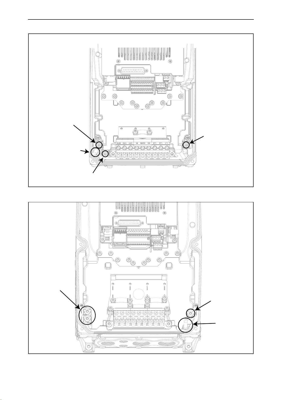
The power-head is earthed through metal aglets, located on the terminal-box, which fit into spring
baskets on the powerhead. See Figure 1, Figure 2 and Figure 3 for the location of the screws (three
for MM4 and MM5, two for MM6) and the metal aglets (one for MM4 and MM5, two for MM6). Please,
pay attention not to damage or remove these aglets.
Local contacts: https://www.danfoss.com/en/contact-us/contacts-list/
vacon • 10 Safety
Earth connection
Metal aglet
Earth connection
Earth connection
Earth connections
Metal aglet
Earth connection
Figure 1. Earth connections and metal aglet in MM4
Figure 2. Earth connections and metal aglet in MM5
Local contacts: https://www.danfoss.com/en/contact-us/contacts-list/
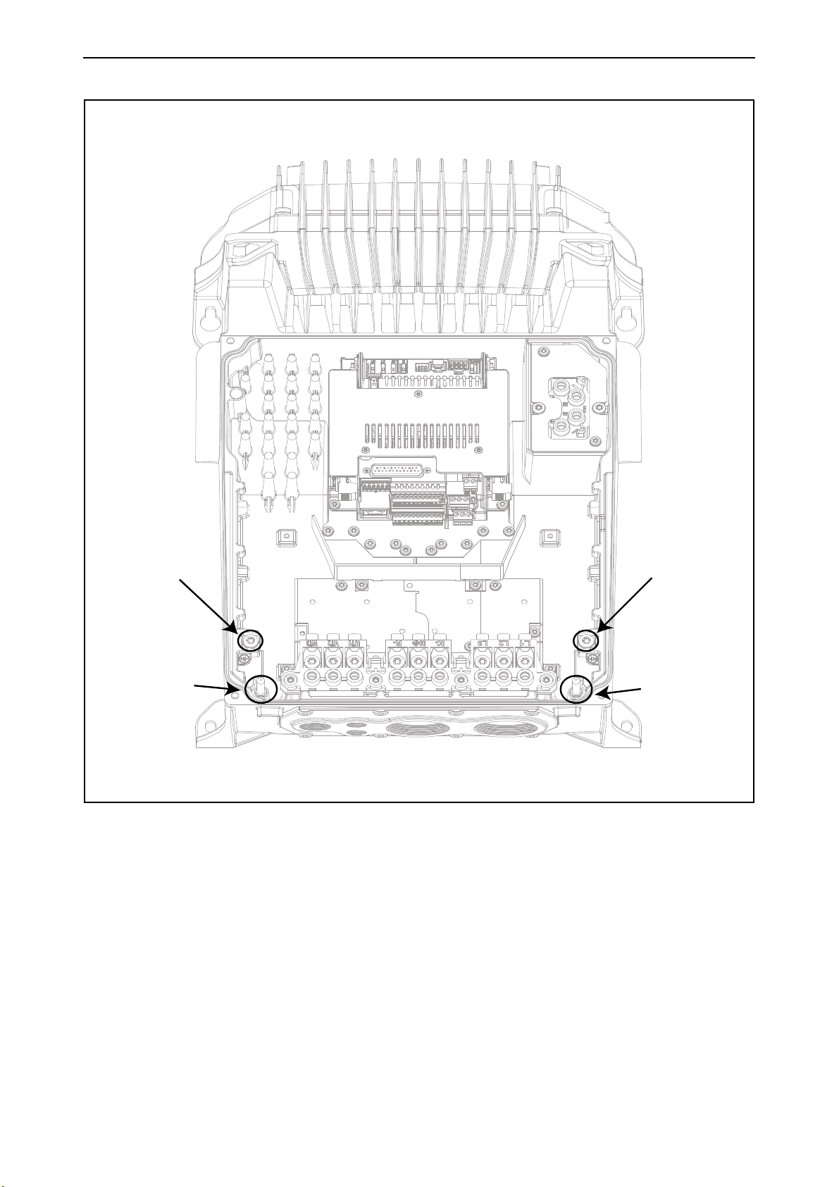
Safety vacon • 11
Earth connection Earth connection
Metal aglet
Metal aglet
Figure 3. Earth connections and metal aglet in MM6
However, always follow the local regulations for the minimum size of the protective grounding
conductor.
NOTE: Due to the high capacitive currents present in the AC drive, fault current protective switches
may not function properly.
Local contacts: https://www.danfoss.com/en/contact-us/contacts-list/
vacon • 12 Safety
POWER UNIT
L1
L2
L3
U
V
W
R01 __
R02 __
DC- DC+/R+ R-
10Vref __
Analog Inputs __
Digital Inputs__
Digital Outputs__
24V __
Ethernet __
RS485 __
STO __
___Thermistor
Keypad
CONTROL UNIT
Reinforced
Mains
Mains
DVC A
DVC A or
Mains
(*)
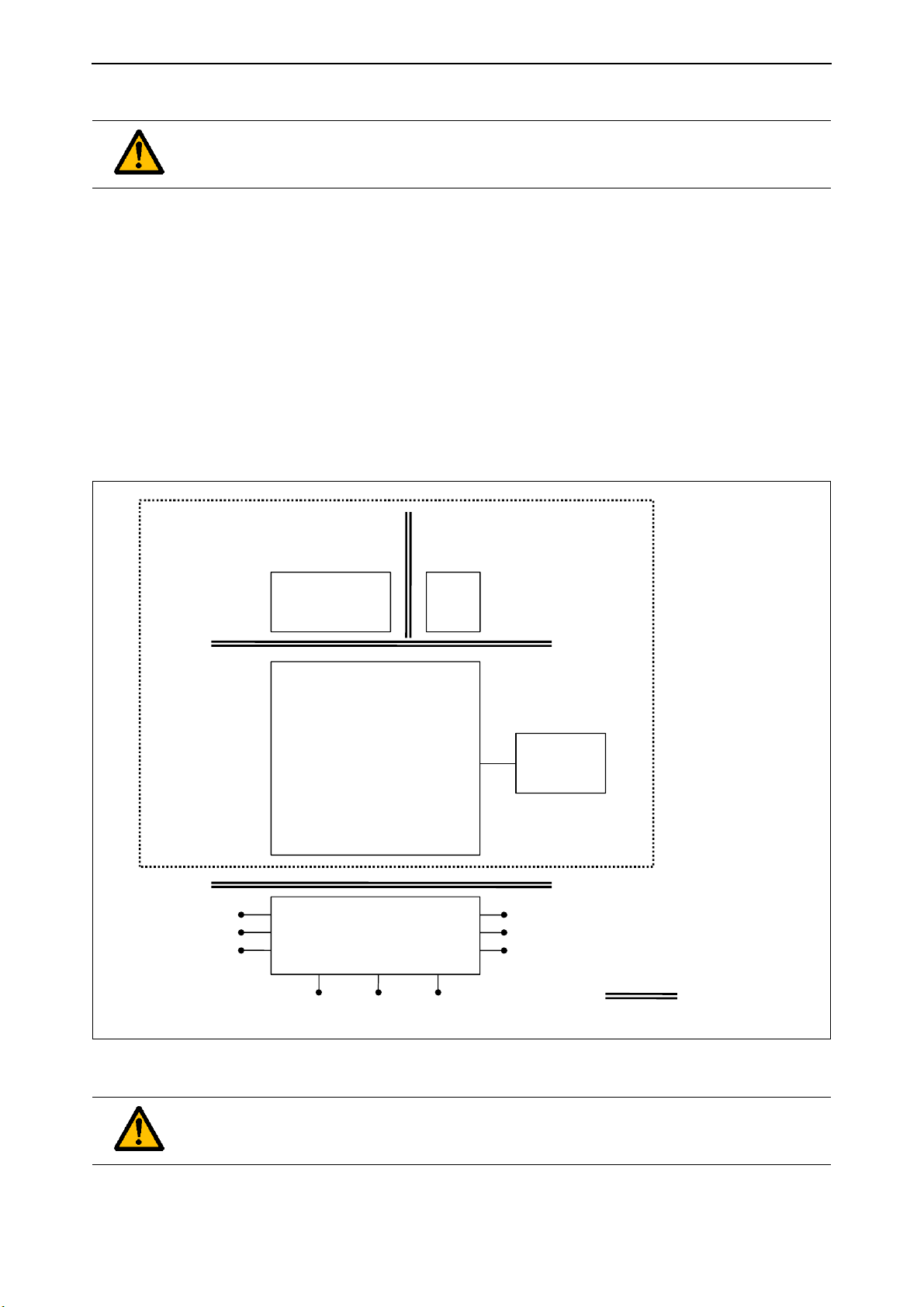
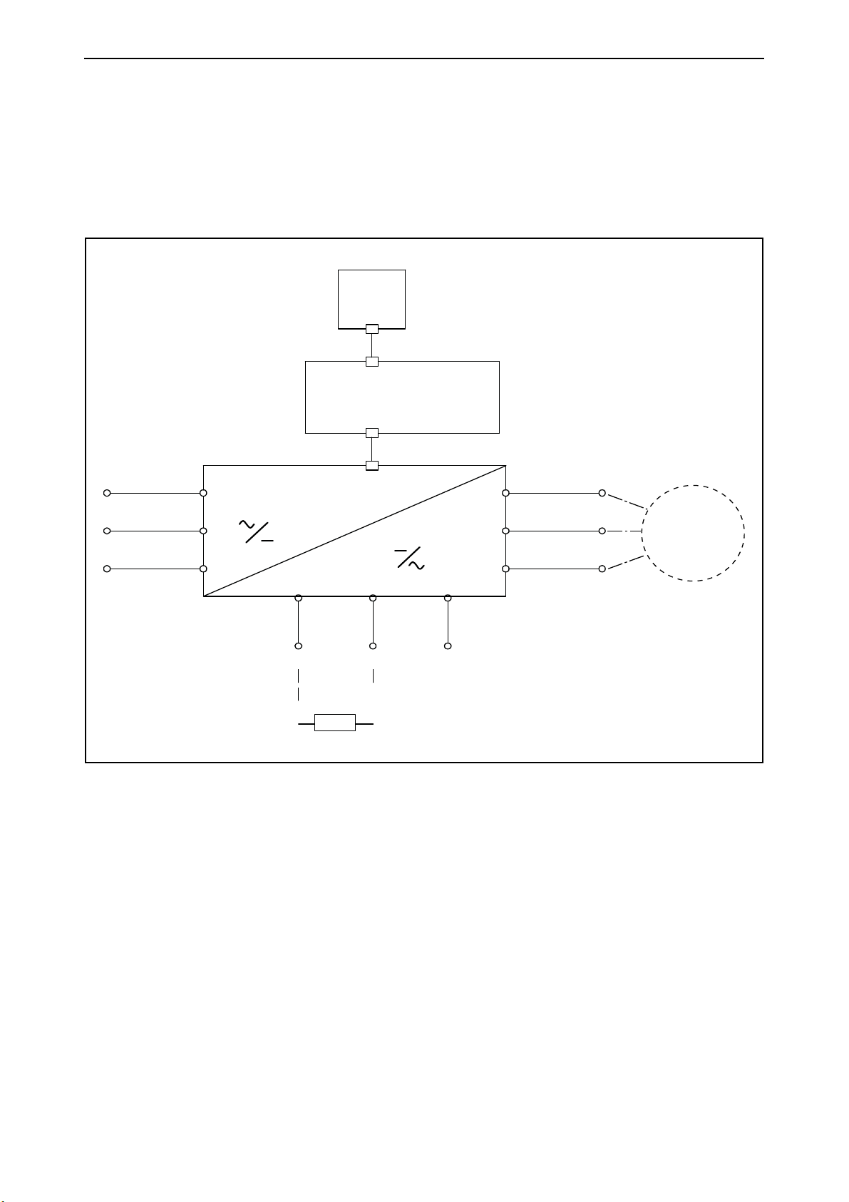
1.6 Insulation system
Please, consider carefully the insulation system depicted in Figure 4 before connecting any circuit to the unit.
A distinction has to be made for the following three groups of terminals, according the insulation
system of VACON® 100 X:
• Mains and motor connections (L1, L2, L3, U, V, W)
• Relays (R01, R02)
• Thermistor-input
• Control terminals (I/Os, RS485, Ethernet, STO)
The Control terminals (I/Os, RS485, Ethernet, STO) are isolated from the Mains (the insulation is reinforced, according to IEC 61800-5-1) and the GND terminals are referred to PE.
This is important when you need to connect other circuits to the drive and test the complete assembly. Should you have any doubt or question, please contact your local distributor.
(*)
(*)
The relays may be used also with DVC A circuits. This is possible only if both relays
are used with DVC A circuit: to mix Mains and DVC A is not allowed.
Figure 4. Insulation system
Local contacts: https://www.danfoss.com/en/contact-us/contacts-list/
Safety vacon • 13
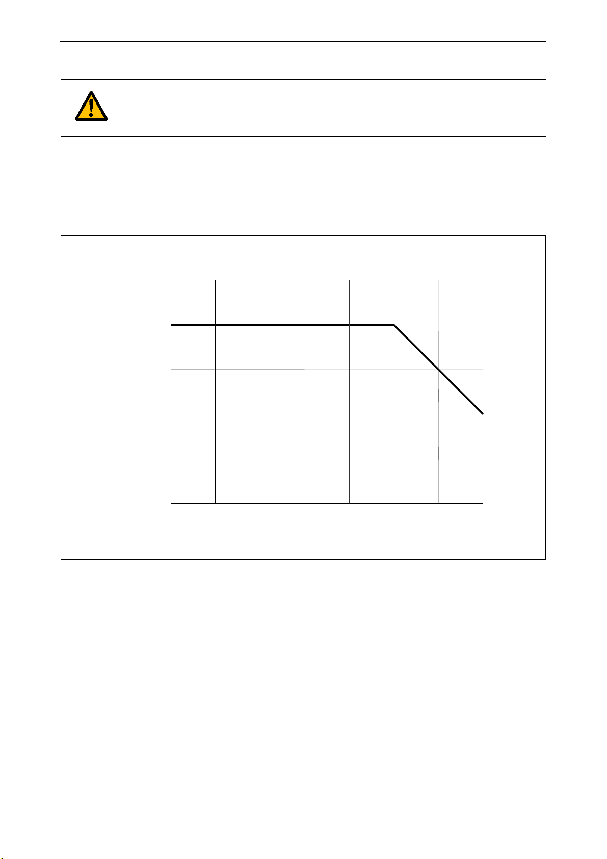
Ambient temperature (°C)
Percent rated output current (% I
N
)
10 20 30 40 50
100
75
50
25
0-10
150
60
Temperature - Output Current Derating Curve
1.7 Compatibility with RCDs
This product can cause a d.c. current in the protective grounding conductor. Where a
residual current-operated protective (RCD) or monitoring (RCM) device is used for
protection in case of direct or indirect contact, only an RCD or RCM of Type B is allowed
on the supply side of this product.
1.8 Extended temperature range
VACON® 100 X has an integrated cooling system, independent from the motor fan. Under maximum operating conditions, the ambient temperature cannot exceed 40 °C. See Table and Table 31
for the output rated current. Higher temperatures are allowed only with derating of the output current. With derating the unit can operate up to 60°C. See the Figure 5.
Figure 5. Temperature-output current derating curve
NOTE: the maximum allowed switching frequency above 50°C is 1.5 kHz.
The AC drive is cooled down by air-ventilation. Therefore, make sure that enough free space is left
around the AC drive to ensure sufficient air circulation (see for more details the mounting instructions on chapter 3).
1.9 Electro-magnetic compatibility (EMC)
The VACON® 100 X complies with IEC 61000-3-12, provided that the short circuit ratio (R
greater than or equal to 120 at the interface point between the user's supply and the public system.
It is the responsibility of the installer or user of the equipment to ensure, by consultation with the
distribution network operator if necessary, that the equipment is connected only to a supply with a
short-circuit ratio R
Local contacts: https://www.danfoss.com/en/contact-us/contacts-list/
greater than or equal to 120.
SCE
SCE
) is

vacon • 14 Safety
1.10 Marine environment
For installation, safety and EMC requirements in a marine environment download and read the Marine Installation Guide.
NOTE! You can download the English and French product manuals with applicable safety,
warning and caution information from https://www.danfoss.com/en/service-and-support/.
REMARQUE Vous pouvez télécharger les versions anglaise et française des manuels produit
contenant l’ensemble des informations de sécurité, avertissements et mises en garde
applicables sur le site https://www.danfoss.com/en/service-and-support/.
Local contacts: https://www.danfoss.com/en/contact-us/contacts-list/
Receiving the delivery vacon • 15
44023949
M163500721
70SCO00387
Danfoss A/S, 6430 Nordborg, Denmark
P2: 18.5 kW: 400 V / 25 hp: 480 V
IP66
U2: 3AC 0-Input V 0-320 Hz, I2: 38 A
U1: 3AC 380-480 V 50/60 Hz, I1: 36.7 A
Made in Italy
POWER:
OUTPUT:
INPUT:
VACON DRIVES A/S
VACON0100-3L-0038-4-X+HMGR
160907
FW0072V021
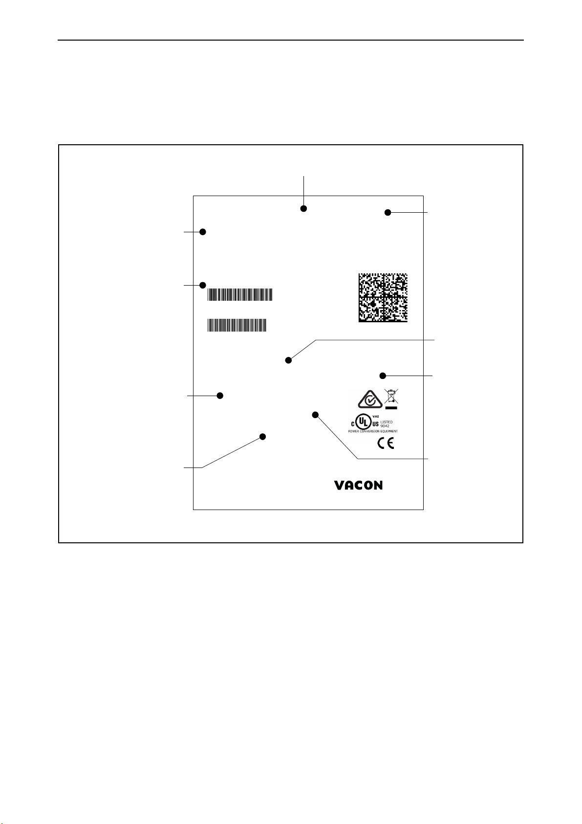
Marks:
Cust. Ord. No:
Application:
Firmware:
B.ID:
M163500721
S/N:
70SCO00387
Code:
Type:
AC DRIVE
Vacon type code
Rated
current
Supply
voltage
Application
code
EMC level
IP class
Serial number
Customer’s
order number
Vacon order
number
Batch ID
2. R
ECEIVING THE DELIVERY
Check the correctness of delivery by comparing your order data to the drive information found on
the package label. If the delivery does not correspond to your order, contact the supplier immediately. See chapter 2.4.
Local contacts: https://www.danfoss.com/en/contact-us/contacts-list/
Figure 6. VACON® package label

vacon • 16 Receiving the delivery
VACON
This segment is common for all products.
0100
Product range:
0100 = VACON® 100 Product family
3L
Input/Function:
3L = Three-phase input
0061
Drive rating in ampere; e.g. 0061 = 61 A
See Table 30, Table 31 and Table 32 for all
the drive ratings.
4
Supply voltage:
2 = 208-240 V
4 = 380-480 V
5 = 380-500 V
X
-IP66/ Type 4X
-EMC-level C2
-Two relay outputs
-One thermistor input
-STO function
-GP software package installed
R02
+EMC4
+LS60
+LSUS
+QGLC
+xxxx +yyyy
Additional codes (Several options possible).
Examples of additional codes:
+HMGR
Graphical keypad IP66
+SRBT
Integrated battery for real time clock
+FBIE
Onboard fieldbus protocols activated
(EtherNet/IP and PROFINET IO)
+A1181
Solar pump application
2.1 Type designation code
VACON® type designation code is formed of a nine-segment code and optional +codes. Each segment of the type designation code uniquely corresponds to the product and options you have ordered. The code is of the following format:
VACON0100-3L-0061-4-X +xxxx +yyyy
Local contacts: https://www.danfoss.com/en/contact-us/contacts-list/
Receiving the delivery vacon • 17
2.2 order codes
The order codes for VACON® 100 X drive family are shown in the following table:
Table 3. Order codes of VACON® 100 X. See chapter 7 for more details.
Enclosure size Order code Description
Supply voltage 3AC 208-240V
VACON0100-3L-0006-2-X 1.1 kW - 1.5 HP drive
MM4
MM5
MM6
Supply voltage 3AC 380-480V
MM4
MM5
VACON0100-3L-0008-2-X 1.5 kW - 2.0 HP drive
VACON0100-3L-0011-2-X 2.2 kW - 3.0 HP drive
VACON0100-3L-0012-2-X 3.0 kW - 4.0 HP drive
VACON0100-3L-0018-2-X 4.0 kW - 5.0 HP drive
VACON0100-3L-0024-2-X 5.5 kW - 7.5 HP drive
VACON0100-3L-0031-2-X 7.5 kW - 10.0 HP drive
VACON0100-3L-0048-2-X 11.0 kW - 15.0 HP drive
VACON0100-3L-0062-2-X 15.0 kW - 20.0 HP drive
VACON0100-3L-0003-4-X 1.1 kW - 1.5 HP drive
VACON0100-3L-0004-4-X 1.5 kW - 2.0 HP drive
VACON0100-3L-0005-4-X 2.2 kW - 3.0 HP drive
VACON0100-3L-0008-4-X 3.0 kW - 4.0 HP drive
VACON0100-3L-0009-4-X 4.0 kW - 5.0 HP drive
VACON0100-3L-0012-4-X 5.5 kW - 7.5 HP drive
VACON0100-3L-0016-4-X 7.5 kW - 10.0 HP drive
VACON0100-3L-0023-4-X 11.0 kW - 15.0 HP drive
VACON0100-3L-0031-4-X 15.0 kW - 20.0 HP drive
MM6
Supply voltage 3AC 380-500V
MM4
MM5
MM6
VACON0100-3L-0038-4-X 18.5 kW - 25.0 HP drive
VACON0100-3L-0046-4-X 22.0 kW - 30.0 HP drive
VACON0100-3L-0061-4-X 30.0 kW - 40.0 HP drive
VACON0100-3L-0072-4-X 37.0 kW - 50.0 HP drive
VACON0100-3L-0003-5-X 1.1 kW - 1.5 HP drive
VACON0100-3L-0004-5-X 1.5 kW - 2.0 HP drive
VACON0100-3L-0005-5-X 2.2 kW - 3.0 HP drive
VACON0100-3L-0008-5-X 3.0 kW - 4.0 HP drive
VACON0100-3L-0009-5-X 4.0 kW - 5.0 HP drive
VACON0100-3L-0012-5-X 5.5 kW - 7.5 HP drive
VACON0100-3L-0016-5-X 7.5 kW - 10.0 HP drive
VACON0100-3L-0023-5-X 11.0 kW - 15.0 HP drive
VACON0100-3L-0031-5-X 15.0 kW - 20.0 HP drive
VACON0100-3L-0038-5-X 18.5 kW - 25.0 HP drive
VACON0100-3L-0046-5-X 22.0 kW - 30.0 HP drive
VACON0100-3L-0061-5-X 30.0 kW - 40.0 HP drive
VACON0100-3L-0072-5-X 37.0 kW - 50.0 HP drive
Local contacts: https://www.danfoss.com/en/contact-us/contacts-list/
vacon • 18 Receiving the delivery
2.3 Unpacking and lifting the AC drive
The weights of the AC drives vary according to enclosure size. You may need to use a piece of special
lifting equipment to move the drive from its package. Note the weights of each individual enclosure
size in Table below.
Table 4. Enclosure weights.
Enclosure
size
[kg] [lb]
Weight
MM4 8.8 19.4
MM5 14.9 32.8
MM6 31.5 69.4
VACON® 100 X drives have undergone scrupulous tests and quality checks at the factory before they
are delivered to the customer. However, after unpacking the product, check that no signs of transport damage are to be found on the product and that the delivery is complete.
Should the drive have been damaged during shipping, please contact the cargo insurance company
or the carrier in the first instance.
2.4 Accessories
After having opened the transport package and lifted the drive out, check immediately that these
various accessories were included in the delivery. The contents of the accessories bag differ by
drive size:
2.4.1 Enclosure MM4
Table 5. Content of accessory bag, MM4.
Item Quantity Purpose
STO terminal connector 1
M4 x 12 DIN6900-3-Combi-Delta-Tx
screw
10 Screws for control cable clamps
Six pin black connector (see
Figure 7) to use STO function
M1-3 Cable clamp 5 Clamping control cables
M4 x 12 DIN6900-3-Combi-Delta-Tx
screw
6 Screws for power cable clamps
M25 Cable clamp 3 Clamping power cables
‘Product modified’ sticker 1 Information about modifications
HMI cap
*. Provided only if the drive is delivered with the keypad.
*
1 Closing cap for the HMI connector
Local contacts: https://www.danfoss.com/en/contact-us/contacts-list/
Receiving the delivery vacon • 19
2.4.2 Enclosure MM5
Table 6. Content of accessory bag, MM5.
Item Quantity Purpose
STO terminal connector 1
M4 x 12 DIN6900-3-Combi-Delta-Tx
screw
10 Screws for control cable clamps
Six pin black connector (see
Figure 7) to use STO function
M1-3 Cable clamp 5 Clamping control cables
M4 x 12 DIN6900-3-Combi-Delta-Tx
screw
6 Screws for power cable clamps
M32 Cable clamp 3 Clamping power cables
‘Product modified’ sticker 1 Information about modifications
HMI cap
*. Provided only if the drive is delivered with the keypad.
*
1 Closing cap for the HMI connector
2.4.3 Enclosure MM6
Table 7. Content of accessory bag, MM6.
Item Quantity Purpose
STO terminal connector 1
M4 x 12 DIN6900-3-Combi-Delta-Tx
screw
10 Screws for control cable clamps
Six pin black connector (see
Figure 7) to use STO function
M1-3 Cable clamp 5 Clamping control cables
M4 x 25 DIN6900-3-Combi-Delta-Tx
screw
6 Screws for power cable clamps
M40 Cable clamp 3 Clamping power cables
‘Product modified’ sticker 1 Information about modifications
HMI cap
*. Provided only if the drive is delivered with the keypad mounted.
*
1 Closing cap for the HMI connector
Local contacts: https://www.danfoss.com/en/contact-us/contacts-list/
vacon • 20 Receiving the delivery
Product modified
Date:
Date:
Date:
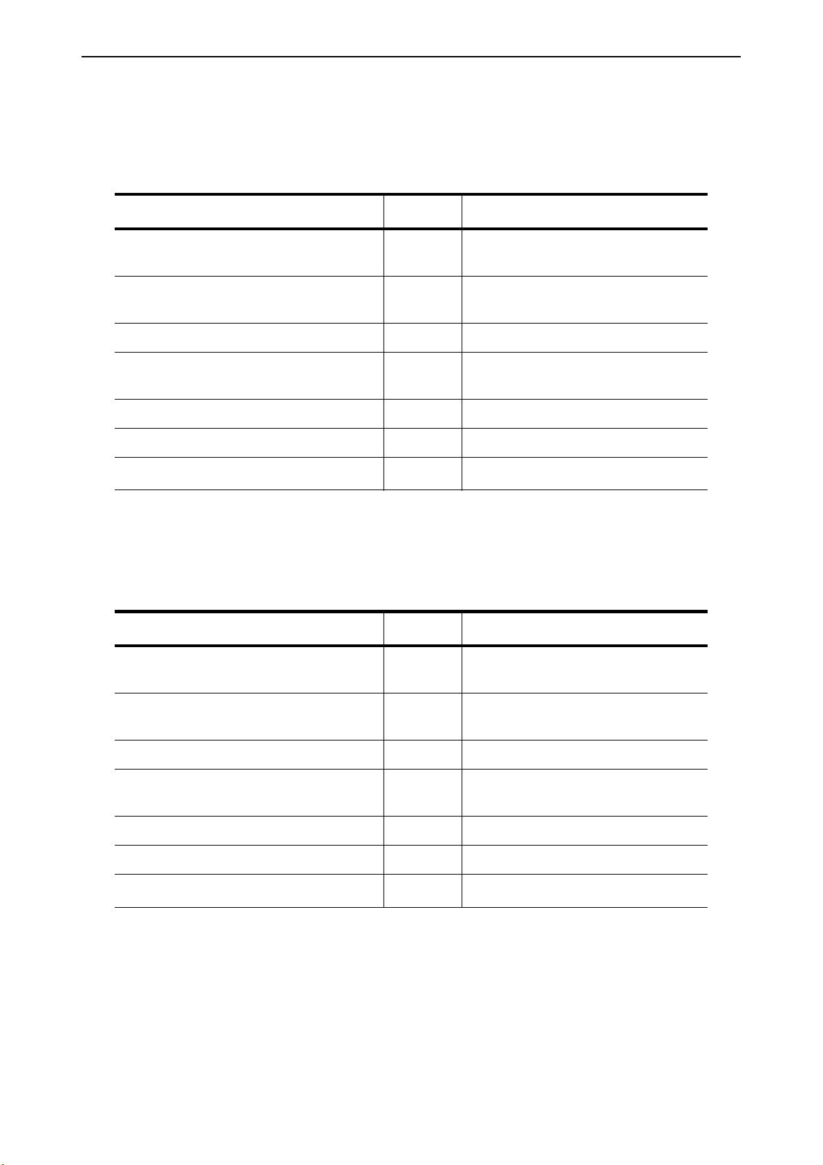
2.4.4 STO terminal connector
Figure 7. STO connector
2.4.5 ‘Product modified’ sticker
In the small plastic bag included in the delivery you will find a silver
Product modified
sticker. The
purpose of the sticker is to notify the service personnel about the modifications made in the AC
drive. Attach the sticker on the side of the AC drive to avoid losing it. Should the AC drive be later
modified, mark the change on the sticker.
Figure 8. ‘Product modified’ sticker
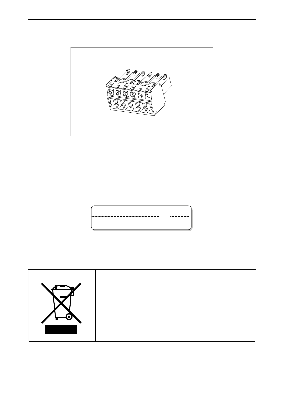
2.4.6 Disposal
When the device reaches the end of its operating life do not dispose
of it as a part of standard household garbage. Main components of
the product can be recycled, but some need to be fragmented to
separate different types of materials and components that need to
be treated as special waste from electrical and electronic
components. To ensure environmentally sound and safe recycling
treatment, the product can be taken to appropriate recycling center
or returned to the manufacturer.
Observe local and other applicable laws as they may mandate
special treatment for specific components or special treatment may
be ecologically sensible.
Local contacts: https://www.danfoss.com/en/contact-us/contacts-list/
Mounting vacon • 21
315,3
190,7
187,8
213,8
293,0
296,5
5
,
9
143,5
196,4
3. M
OUNTING
VACON® 100 X is the ideal solution for a decentralised installation. It is conceived to be mounted on
a wall or directly on the motor, saving space and reducing the cabling complexity. In both cases, it
must be ensured that the mounting plane is even.
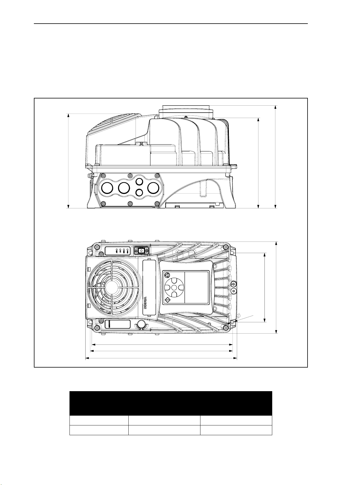
3.1 Dimensions MM4
Figure 9. VACON® 100 X drive dimensions, MM4
Dimensions W x H x D
Enclosure size
[mm] [in]
MM4 190.7 x 315.3 x 196.4 7.51 x 12.41 x 7.73
MM4 +HMGR 190.7 x 315.3 x 213.8 7.51 x 12.41 x 8.42
Local contacts: https://www.danfoss.com/en/contact-us/contacts-list/
vacon • 22 Mounting
367,4
203,7
230,8
180,0
345,2
349,2
6
,
1
232,6
213,5
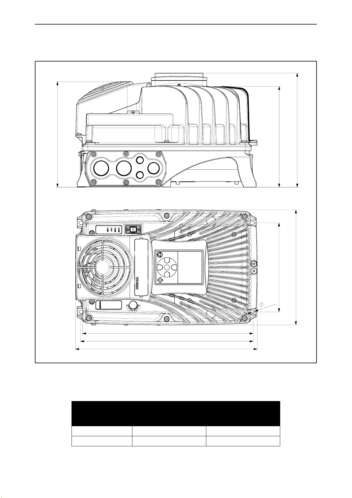
3.2 Dimensions MM5
Figure 10. VACON® 100 X drive dimensions, MM5
Dimensions W x H x D
Enclosure size
[mm] [in]
MM5 232.6 x 367.4 x 213.5 9.16 x 14.46 x 8.41
MM5 +HMGR 232.6 x 367.4 x 230.8 9.16 x 14.46 x 9.08
Local contacts: https://www.danfoss.com/en/contact-us/contacts-list/
Mounting vacon • 23
229,6
254,2
322,0
349,5
382,8
385,3
499,8
8
,
2
235,4
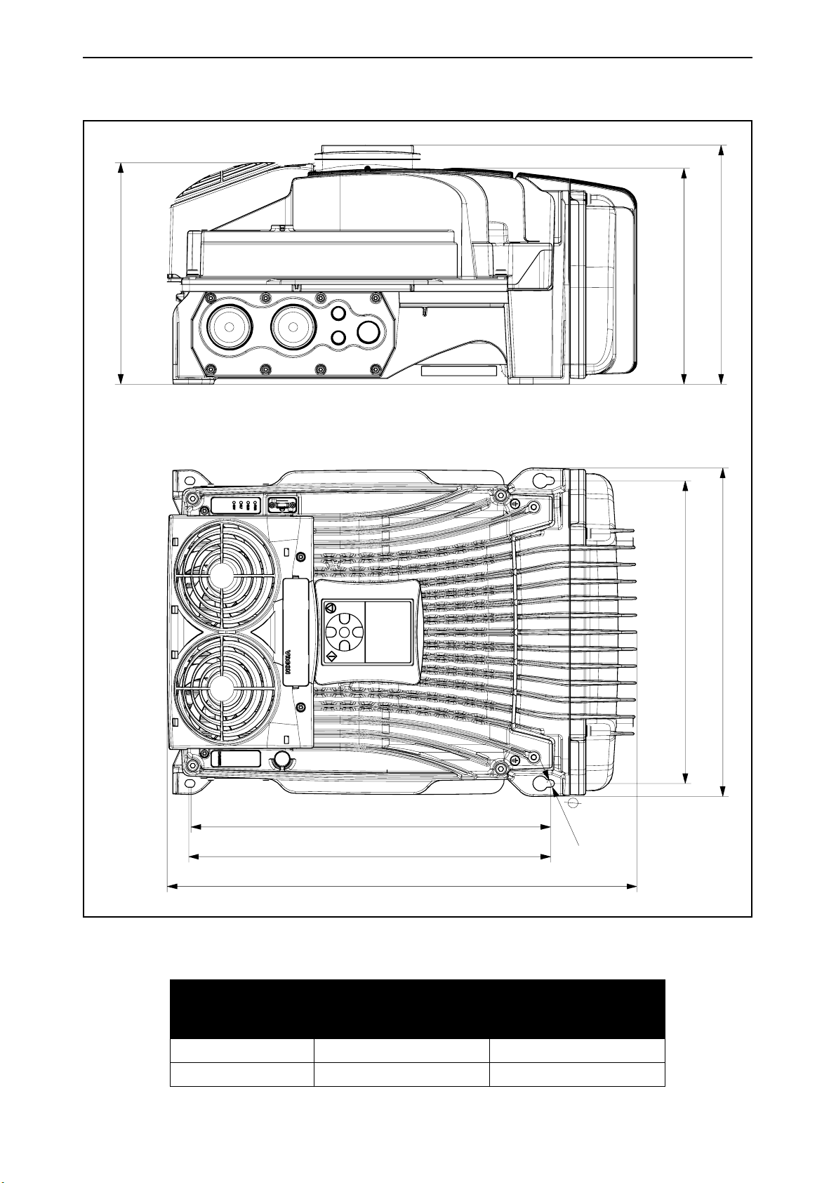
3.3 Dimensions MM6
Figure 11. VACON® 100 X drive dimensions, MM6
Dimensions W x H x D
Enclosure size
[mm] [in]
MM6 349.5 x 499.8 x 235.4 13.76 x 19.68 x 9.27
MM6 +HMGR 349.5 x 499.8 x 254.2 13.76 x 19.68 x 10.00
Local contacts: https://www.danfoss.com/en/contact-us/contacts-list/
vacon • 24 Mounting
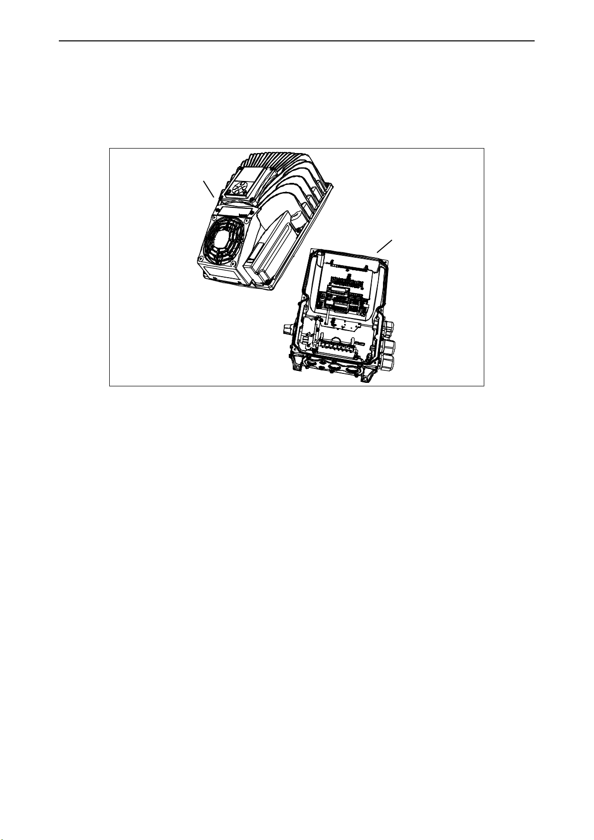
Powerhead
Terminal box
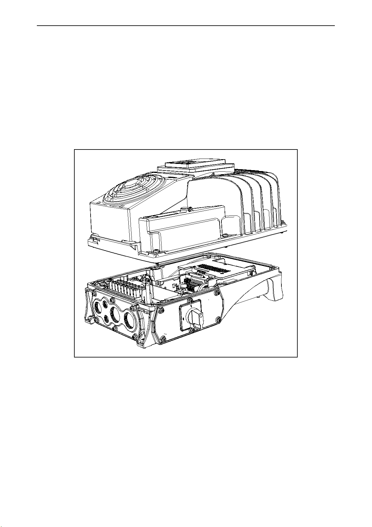
3.4 Introduction of modules
The mechanical concept of VACON® 100 X drive is based on two segregated parts, power and control, connected to each other by pluggable terminals. The power unit, called powerhead, includes
all the power electronics such as the EMC-filter, IGBTs, capacitors, choke or power boards while
the control board and the control terminals are located in the terminal box.
Figure 12. VACON® 100 X drive modules
Local contacts: https://www.danfoss.com/en/contact-us/contacts-list/
Mounting vacon • 25
3.5 Mounting
The drive consists of two main elements:
1. The terminal box that includes the power terminals and control board with the control terminals
and
2. The powerhead containing all the power electronics.
To install the drive, both parts need to be separated. The terminal box must be fixed first and all
cabling done. After this, the powerhead will be plugged on the terminal box and fixed with 4 (MM4
and MM6) or 6 (MM5) dedicated screws located on top side of the powerhead (see Figure 13.). In order to guarantee specified IP protection, recommended fastening torque is 2-3 Nm. The screws
must be tightened crosswise.
Figure 13. Separation of modules (MM5 example)
Local contacts: https://www.danfoss.com/en/contact-us/contacts-list/
vacon • 26 Mounting
3.5.1 Wall-mounting
The drive can be mounted in vertical or horizontal position on the wall or any other relatively even
mounting plane or machine frame and fixed with the screws recommended in Table 8.
Recommended screw or bolt size for MM4 is M5, for MM5 M6 and MM6 is M8.
Table 8. Screws for wall mounting.
Enclosure
size
Screw number Screw size
MM4 4 M5
MM5 4 M6
MM6 4 M8
3.5.2 Motor-mounting
The drive can also be mounted on a motor (on top or on any side of the motor). The drive is equipped
with a cooling system independent of the motor. Motor-mounting requires special adapting components. Contact your local distributor for additional information.
3.5.3 Segregated modules
In order to ease replacements in case of failure, the power and the control sub-systems are enclosed in two segregated parts, connected together through pluggable terminals:
• Power-head: heat-sink enclosing all power electronics
• Terminal-box: block containing unit control and power terminals
Firstly, the terminal-box has to be fixed and the cabling has to be done. Secondly, the power-head
has to be plugged and fixed to the terminal-box with dedicated screws (see Table 9). In order to preserve the specified IP protection class, the recommended fastening torque is 2-3 Nm.
Table 9. Screws for fixing the powerhead to the terminal box.
Enclosure
size
Screw number Screw size
MM4 4 M5
MM5 6 M5
MM6 4 M6
Local contacts: https://www.danfoss.com/en/contact-us/contacts-list/
Mounting vacon • 27
B
C
AAA
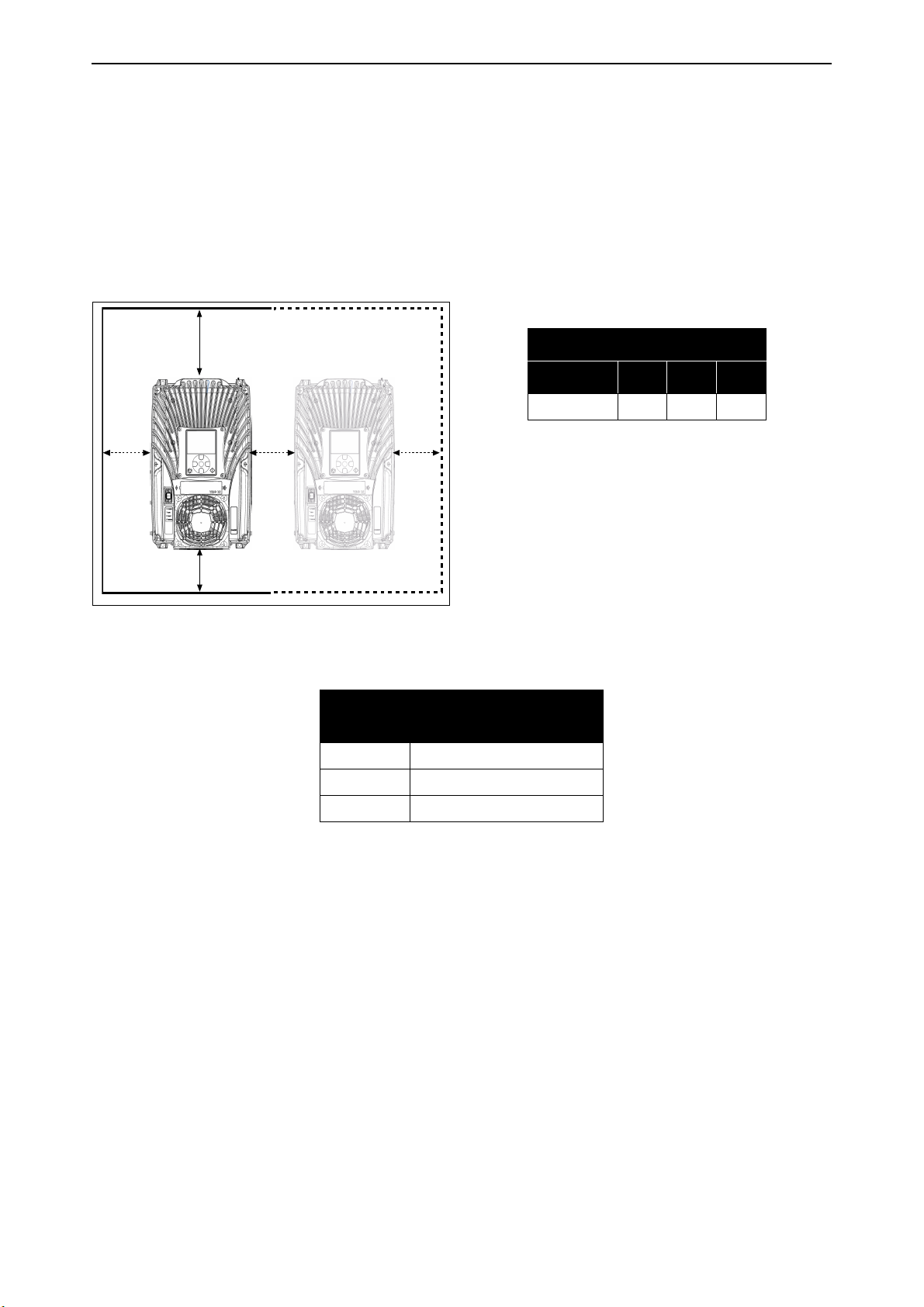
3.6 Cooling
The AC drive produces heat in operation and is cooled down by air circulated by a fan. The cooling
concept is independent of the motor fan.
Enough free space must be left around the AC drive to ensure sufficient air circulation and cooling.
Different acts of maintenance may also require a certain amount of free space.
The minimum clearances given in Table 10 must not be exceeded. It is also important to ensure that
the temperature of the cooling air does not exceed the maximum ambient temperature of the drive.
Contact local distributor for more information on required clearances in different installations.
Min clearance [mm]
Type A B C
All types 80 160 60
Table 10. Min. clearances around AC drive.
A = Clearance left and right from the drive
B = Clearance above the drive
C = Clearance underneath the AC drive
Figure 14. Installation space
Table 11. Required cooling air.
Type
Cooling air required
[m3/h]
MM4 140
MM5 140
MM6 280
Should you need further details on the cooling system of the VACON® 100 X, please contact your
local distributor.
Local contacts: https://www.danfoss.com/en/contact-us/contacts-list/
vacon • 28 Power cabling
U/T1
V/T2
W/T3
M
L1
L2
L3
DC+
R-
DC-
Keypad
Control unit
Power unit
4. P
The mains cables are connected to terminals L1, L2 and L3 and the motor cables to terminals
marked with U, V and W. See principal connection diagram in Figure 15. See also Table 12 for the
cable recommendations for different EMC levels.
OWER CABLING
Figure 15. Principal connection diagram
Use cables with heat resistance in accordance with the application requirements. The cables and
the fuses must be dimensioned according to the AC drive nominal OUTPUT current which you can
find on the rating plate.
Local contacts: https://www.danfoss.com/en/contact-us/contacts-list/
Power cabling vacon • 29
Shield
PE conductors
Shield
PE conductor
Table 12. Cable types required to meet standards.
EMC levels
1st environment 2nd environment
Cable type
Category C2 Category C3 Category C4
Mains cable 1 1 1
Motor cable 3* 2 2
Control cable 4 4 4
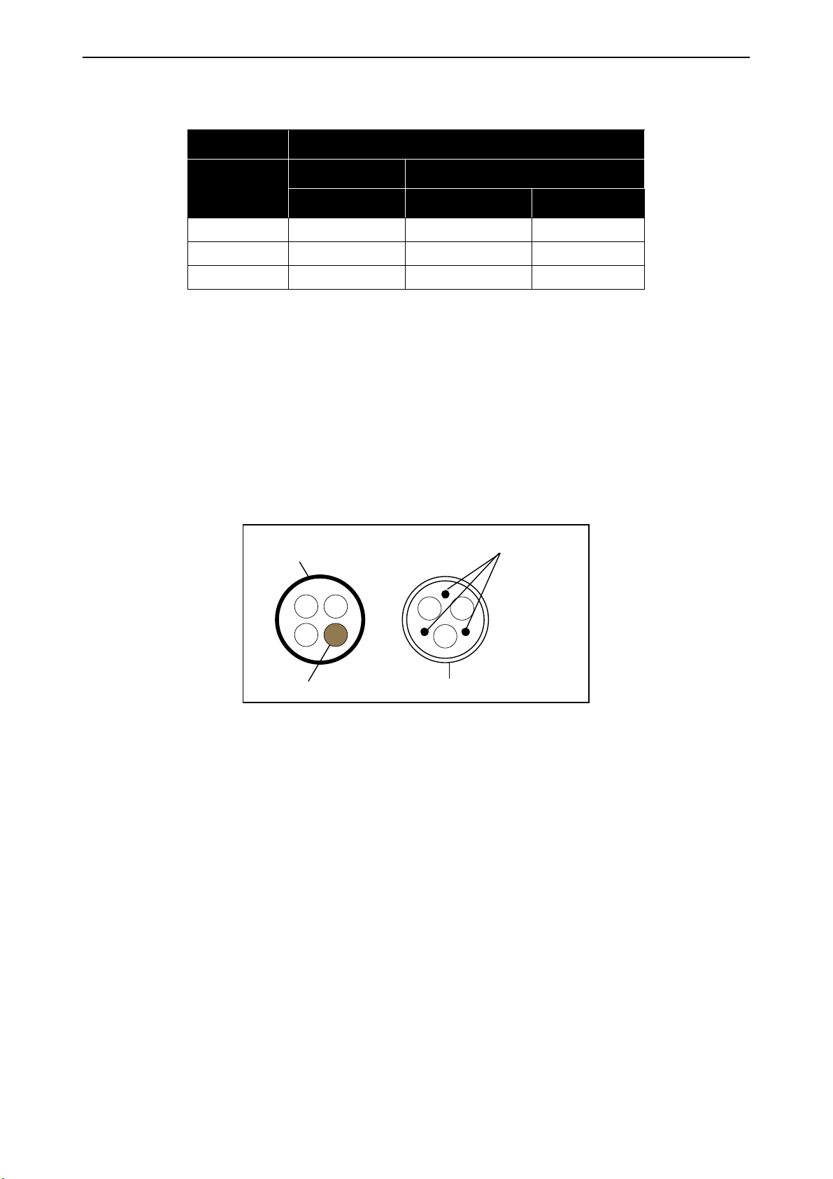
1 = Power cable intended for fixed installation and the specific mains voltage. Shielded cable not
required. (MCMK or similar recommended).
2 = Symmetrical power cable equipped with concentric protection wire and intended for the spe-
cific mains voltage. (MCMK or similar recommended). See Figure 16.
3 = Symmetrical power cable equipped with compact low-impedance shield and intended for
the specific mains voltage. [MCCMK, EMCMK or similar recommended. See Figure 16.
*360º grounding of the shield with cable glands in motor end needed for EMC level C2.
4 = Screened cable equipped with compact low-impedance shield (JAMAK, SAB/ÖZCuY-O or
similar).
Figure 16.
NOTE: The EMC requirements are fulfilled at factory defaults of switching frequencies (all frames).
NOTE: If safety switch is connected, the EMC protection must be continuous over the whole cable
installation.
Local contacts: https://www.danfoss.com/en/contact-us/contacts-list/
vacon • 30 Power cabling
4.1 Circuit breaker
Please disconnect the drive via an external circuit breaker. You have to provide a switching device
between supply and main connection terminals.
When connecting the input terminals to the power supply using a circuit breaker, observe that this
is of type B or type C and ensure it has a capacity of 1.5 to 2 times of the inverter’s rated current
(see Table and Table 31).
NOTE: circuit breaker is not allowed in installations where C-UL is required. Only fuses are recommended.
4.2 UL standards on cabling
To meet the UL (Underwriters Laboratories) regulations, use a UL-approved copper cable with a
minimum heat-resistance of +75°C. Use Class 1 wire only.
The units are suitable for use on a circuit capable of delivering not more than 100,000 rms symmetrical amperes, 500V AC maximum, when protected by T or J class fuses.
Integral solid state short circuit protection does not provide branch circuit protection.
Branch circuit protection must be provided in accordance with the National Electrical
Code and any additional local codes.
Local contacts: https://www.danfoss.com/en/contact-us/contacts-list/

Power cabling vacon • 31
PES
AC power supply
Three phases
PE
3AC
Motor
PE
brake
resistor
4.3 Description of the terminals
The following pictures describe the power terminals and the typical connections in
drives.
VACON
®
100 X
Figure 17. Power connections, MM4
Table 13. Terminal description.
Terminal Description
L1
L2
L3
DCDC+/R+
R-
U/T1
V/T2
These terminals are the input connections for the power
supply.
DC bus terminals (DC- DC+)
and
Brake resistor terminals (R+ R-)
These terminals are for motor connections.
W/T3
Local contacts: https://www.danfoss.com/en/contact-us/contacts-list/

vacon • 32 Power cabling
PES
AC power supply
Three phases
PE
3AC
Motor
PE
brake
resistor
Figure 18. Power connections, MM5
Table 14. Terminal description.
Terminal Description
L1
L2
L3
DCDC+/R+
R-
These terminals are the input connections for the power
supply.
DC bus terminals (DC- DC+)
and
Brake resistor terminals (R+ R-)
U/T1
V/T2
These terminals are for motor connections.
W/T3
Local contacts: https://www.danfoss.com/en/contact-us/contacts-list/

Power cabling vacon • 33
PES
AC power supply
Three phases
PE
3AC
Motor
PE
brake
resistor
Figure 19. Power connections, MM6
Table 15. Terminal description.
Terminal Description
L1
L2
L3
DCDC+/R+
R-
These terminals are the input connections for the power
supply.
DC bus terminals (DC- DC+)
and
Brake resistor terminals (R+ R-)
U/T1
V/T2
These terminals are for motor connections.
W/T3
Local contacts: https://www.danfoss.com/en/contact-us/contacts-list/

vacon • 34 Power cabling
4.4 Cable dimensioning and selection
Table 16 and Table 17 show the minimum dimensions of the Cu-cables and the corresponding fuse
sizes.
These instructions apply only to cases with one motor and one cable connection from the AC drive
to the motor. In any other case, ask the factory for more information.
4.4.1 Cable and fuse sizes, enclosures MM4 to MM6
The recommended fuse type is gG/gL (IEC 60269-1). The fuse voltage rating must be selected according to the supply network. The final selection must be made according to local regulations, cable installation conditions and cable specification. Bigger fuses than those recommended below
must not be used.
Check that the fuse operating time is less than 0.4 seconds. Operating time depends on used fuse
type and impedance of the supply circuit. Consult the factory about faster fuses. The manufacturer
also recommends high speed gS (IEC 60269-4) fuse ranges.
Table 16. Cable and fuse sizes for VACON® 100 X.
Enclosure
size
MM4
MM5
Type
0003 4 - 0004 4
0003 5 - 0004 5
0006 2 - 0008 2
0005 4 - 0008 4
0005 5 - 0008 5
0011 2 - 0012 2
0009 4 - 0012 4
0009 5 - 0012 5
0018 2
0016 4
0016 5
0024 2
0023 4
0023 5
0031 2
0031 4
0031 5
Mains, motor
I
INPUT
[A]
Fuse
(gG/gL)
[A]
and brake
resistor*
cable
Cu [mm2]
3.4 - 4.6 6 3*1.5+1.5
6.0 - 7.2
5.4 - 8.1
9.7 - 10.9
9.3 - 11.3
16.1
15.4
21.7
21.3
27.7
28.4
10 3*1.5+1.5
16 3*2.5+2.5
20 3*6+6
25 3*6+6
32 3*10+10
Terminal cable size
Main terminal
[mm2]
0.5—10
0.5—6
0.5—10
0.5—6
0.5—10
0.5—6
0.5—16
or stranded
0.5—16
or stranded
0.5—16
stranded
solid
stranded
solid
stranded
solid
stranded
solid
solid
solid or
Earth terminal
[mm2]
M4
ring terminal
or
1—6
M4
ring terminal
or
1—6
M4
ring terminal or
1—6
M5
ring terminal or
1—10
M5
ring terminal or
1—10
M5
ring terminal or
1—10
MM6
0038 4
0038 5
0048 2
0046 4
0046 5
0062 2
0061 4
0061 5
0072 4
0072 5
36.7 40 3*10+10 M6
43.8
43.6
57.0
58.2
50 3*16+16 M6
63 3*25+16 M6
67.5 80 3*35+16 M6
Local contacts: https://www.danfoss.com/en/contact-us/contacts-list/
ring terminal
ring terminal
ring terminal
ring terminal
M6
ring terminal
M6
ring terminal
M6
ring terminal
M6
ring terminal

Power cabling vacon • 35
The terminal sizes are intended for 1 conductor. For MM6, the max. diameter of the ring terminal is 14 mm.
The cable dimensioning is based on the criteria of the International Standard IEC60364-5-52: Cables must be
PVC-isolated; Max number of parallel cables is 9.
When using cables in parallel,
the max number of cables must be observed.
For important information on the requirements of the grounding conductor, see chapter Grounding and earth
fault protection of the standard.
For the correction factors for each temperature, see International Standard IEC60364-5-52.
NOTE HOWEVER
that the requirements of both the cross-sectional area and
4.4.2 Cable and fuse sizes, enclosures MM4 to MM6, North America
The recommended fuse type is class T (UL & CSA). The fuse voltage rating must be selected according to the supply network. The final selection must be made according to local regulations, cable
installation conditions and cable specification. Bigger fuses than those recommended below must
not be used.
Check that the fuse operating time is less than 0.4 seconds. Operating time depends on used fuse
type and impedance of the supply circuit. Consult the factory about faster fuses. The manufacturer
also recommends high speed J (UL & CSA) fuse ranges.
Table 17. Cable and fuse sizes for VACON® 100 X.
Enclosure
size
MM4
MM5
Type
0003 4 - 0004 4
0003 5 - 0004 5
0006 2 - 0008 2
0005 4 - 0008 4
0005 5 - 0008 5
0011 2
0009 4
0009 5
0012 2
0012 4
0012 5
0018 2
0016 4
0016 5
0024 2
0023 4
0023 5
0031 2
0031 4
0031 5
I
INPUT
[A]
Fuse
(class T)
[A]
3.4 - 4.6 6
6.0 - 7.2
5.4 - 8.1
9.7
9.3
10.9
11.3
16.1
15.4
21.7
21.3
27.7
28.4
10
15
20
25
30
40
Mains and
Terminal cable size
motor cable
Cu
AWG14 AWG24-AWG10
AWG14 AWG24-AWG10
AWG14 AWG24-AWG10
AWG14 AWG24-AWG10
AWG10 AWG20-AWG5
AWG10 AWG20-AWG5
AWG8 AWG20-AWG5
Main terminal Earth terminal
AWG17-AWG10
M4
ring
terminal
AWG17-AWG10
M4
ring
terminal
AWG17-AWG10
M4
ring
terminal
AWG17-AWG10
M4
ring
terminal
AWG17-AWG8
M5
ring
terminal
AWG17-AWG8
M5
ring
terminal
AWG17-AWG8
M5
ring
terminal
Local contacts: https://www.danfoss.com/en/contact-us/contacts-list/

vacon • 36 Power cabling
Table 17. Cable and fuse sizes for VACON® 100 X.
Enclosure
size
Type
0038 4*
0038 5*
0048 2*
0046 4*
0046 5*
I
INPUT
[A]
Fuse
(class T)
36.7 50
43.8
43.6
[A]
60
Mains and
motor cable
Cu
AWG4
AWG4
Terminal cable size
Main terminal Earth terminal
AWG13-AWG0
M6
ring terminal
AWG13-AWG0
M6
ring
terminal
AWG13-AWG2
M6
ring
terminal
AWG13-AWG2
M6
ring
terminal
MM6
0062 2**
0061 4**
0061 5**
0072 4**
0072 5**
* With the optional mains switch, the mains cable must be rated AWG6 (minimum 75ºC, Cu). The motor cable
must be rated AWG4 (minimum 75ºC, Cu).
** The optional mains switch cannot be used with these models, unless current derating is applied. The input
current cannot exceed 52 A at 30°C ambient temperature and 45 A at 40°C ambient temperature. With the
optional main switch, use a maximum 60 A fuse.
The cable dimensioning is based on the criteria of the Underwriters’ Laboratories UL508C:Cables must be
PVC-isolated; Max ambient temperature +40 °C (104 °F), max temperature of cable surface +75 °C (167 °F);
Use only cables with concentric copper shield; Max number of parallel cables is 9.
57.0
58.2
80
67.5 100
AWG4
AWG2
AWG13-AWG0
M6
ring
terminal
AWG9-AWG2/0
M6
ring
terminal
AWG13-AWG2
M6
ring
terminal
AWG9-AWG2/0
M6
ring
terminal
When using cables in parallel, NOTE HOWEVER that the requirements of both the cross-sectional area and
the max number of cables must be observed.
For important information on the requirements of the grounding conductor, see standard Underwriters’ Laboratories UL508C.
For the correction factors for each temperature, see the instructions of standard Underwriters’ Laboratories
UL508C.
4.4.3 Brake resistor cables
VACON® 100 X AC drives are equipped with terminals for an optional external brake resistor. These
terminals are marked with DC+/R+ and R-. See Table 33 and Table 34 for the resistor ratings and
Table 16 for cable sizing.
4.4.4 Control cables
For information on control cables see chapter Control unit.
Local contacts: https://www.danfoss.com/en/contact-us/contacts-list/

Power cabling vacon • 37
D1
B1
C1
A1
D2
C2
Earth conductor
MAINS MOTOR
Shield
E
Earth conductor
4.5 Cable installation
• Before starting, check that none of the components of the AC drive is live. Read carefully the
warnings in chapter 1.
• Place the motor cables sufficiently far from other cables.
• Avoid placing the motor cables in long parallel lines with other cables.
• If the motor cables run in parallel with other cables note the minimum distances between
the motor cables and other cables given in table below.
Distance between
cables, [m]
0.3 ≤ 50
1.0 ≤ 200
• The given distances also apply between the motor cables and signal cables of other systems.
• The maximum lengths of motor cables (shielded) are 100 m (MM4) and 150 m (MM5 and
MM6).
• The motor cables should cross other cables at an angle of 90 degrees.
• If cable insulation checks are needed, see chapter Cable and motor insulation checks.
Start the cable installation according to the instructions below:
1
Strip the motor and mains cables as recommended below.
Shielded
cable, [m]
Local contacts: https://www.danfoss.com/en/contact-us/contacts-list/
Figure 20. Stripping of cables

vacon • 38 Power cabling
Table 18. Cables stripping lengths [mm].
Enclosure
size
MM4 15 70 10 30 7 30
MM6 20 90 15 60 15 60
IEC installation:
2
3
A1 B1 C1 D1 C2 D2 E
as short as possibleMM5 20 70 10 40 10 40
• Remove the cable entry plate. The cable entry system is a combination of a
cable entry plate (see the figure below) and cable glands. In the cable entry
plate there are several openings available for the cables with ISO metric
thread.
• Open only the inlet holes where you need to run the cables.
• Choose the correct cable glands according to drive and cable size as shown in
the following pictures.
Figure 21. Cable entry plate, MM4
Local contacts: https://www.danfoss.com/en/contact-us/contacts-list/

Power cabling vacon • 39
Figure 22.Cable entry plate, MM5
Figure 23.Cable entry plate, MM6
Local contacts: https://www.danfoss.com/en/contact-us/contacts-list/

vacon • 40 Power cabling
• Cable glands must be made of plastic materials. They are used for sealing
4
cables passing through cable entries to ensure the characteristics of the
enclosure.
Figure 24.Cable gland
Plastic cable glands are recommend. If metal cable glands are needed, all insulation system requirements and all protective grounding requirements have to be
fulfilled in accordance with the national electrical regulations and IEC 61800-5-1.
5
Tightening torques of cable glands:
• Screw the cable glands on the cable entry holes using the proper tightening
torque as shown in Table 19.
Table 19. Tightening torque and dimension of cable glands.
Enclosure
size
MM4
MM5
Gland screw
type [metric]
M16 1.0 8.9
M25 4.0 35.5
M16 1.0 8.9
M25 4.0 35.5
M32 7.0 62.1
Tightening torque [Nm]/[lb-in.]
[Nm] lb-in.
MM6
M16 1.0 8.9
M25 4.0 35.5
M40 10.0 88.7
Local contacts: https://www.danfoss.com/en/contact-us/contacts-list/

Power cabling vacon • 41
UL installation:
• To connect NPT pipes to VACON® 100 X, use the optional metal cable entry
plate (included in -R02 option) to meet UL installation rules.
6
• One metal conduit plate with accessories (screws and gasket) is delivered in a
separate bag together with the drive. See the following figures for more
details.
Figure 25.Cable entry plate, MM4 UL installation
Local contacts: https://www.danfoss.com/en/contact-us/contacts-list/

vacon • 42 Power cabling
Figure 26.Cable entry plate, MM5 UL installation
Figure 27.Cable entry plate, MM6 UL installation
Local contacts: https://www.danfoss.com/en/contact-us/contacts-list/

Power cabling vacon • 43
7
• All the (3) terminal box openings are closed with the standard plastic plates
• The metal cable entry plate for UL installation has to be installed in place of
8
• Flexible or rigid cable conduit can be used.
• Use proper fittings to join and terminate rigid conduit tubing, and protect it
9
• The proper selection of electrical conduit materials, fittings, and installation
• Setscrew fittings are commonly used with conduit; they provide weather tight
10
Cable installation:
• Pass the cables (supply cable, motor cable, brake cable and I/O cables) through
11
12
13
• Detach the cable clamps and the grounding clamps.
Connect the stripped cables:
• Expose the shield of both cables in order to make a 360-degree connection with
• Connect the phase conductors of the supply and motor cables into their
• Form the rest of the cable shield of both cables into “pigtails” and make a
with the metric threads.
one of standard plastic cable entries provided with the default package. The
tightening torque of cable entry plate screws: 1.5 -2.0 Nm (13.2-17.7 lb-in). The
metal cable entry plate has three not-threaded openings: input line, motor and
I/Os and can be mounted only on left or right-hand side of the drive.
from damage too.
are important for safe electrical wiring.
joints that are firm to keep the IP degree of the drive.
the conduits (UL connections) or through the cable glands (IEC connections)
and cable entries.
the cable clamp (reverse the shield over the plastic cover of the cable and fix all
together).
respective terminals.
grounding connection with the clamp. Make the pigtails just long enough to
reach and be fixed to the terminal - no longer.
Local contacts: https://www.danfoss.com/en/contact-us/contacts-list/

vacon • 44 Power cabling
Tightening torques of cable terminals:
Table 20. Tightening torques of terminals.
Enclosure
size
MM4
MM5
MM6
14
Tightening torque
Type
0006 2 - 0012 2
0003 4 - 0012 4
0003 5 - 0012 5
0018 2 - 0031 2
0016 4 - 0031 4
0016 5 - 0031 5
0048 2 - 0062 2
0038 4 - 0072 4
0038 5 - 0072 5
• Check the connection of the earth cable to the motor and the AC drive terminals marked with .
[Nm]/[lb-in.]
Power and motor
terminals
[Nm] lb-in. [Nm] lb-in. [Nm] lb-in.
1.2—1.5 10.6—13.3 1.5 13.3 2.0 17.7
1.2—1.5 10.6—13.3 1.5 13.3 2.0 17.7
4—5 35.4—44.3 1.5 13.3 2.0 17.7
Tightening torque
[Nm]/[lb-in.]
EMC grounding
clamps
Tightening torque,
[Nm]/[lb-in.]
Grounding
terminals
Local contacts: https://www.danfoss.com/en/contact-us/contacts-list/

Control unit vacon • 45
8
8
4
7
5
3
1 2
6
5. C
Remove the powerhead of the drive to reveal the terminal box with the control terminals.
The control unit of the AC drive consists of the control board and additional boards (option boards)
connected to the slot connectors of the control board. The locations of boards, terminals and
switches are presented in Figure 28 below.
ONTROL UNIT
Table 21. Locations of components in control unit.
Number Meaning
1 Control terminals 1-11 (see chapter 5.1.2)
2 Control terminals 12-30, A-B (see chapter 5.1.2)
3 Relay terminals (see chapter 5.1.2)
4 Thermistor input (see chapter 5.1.2)
5 STO terminals
6 DIP switches
7 Ethernet terminal (see chapter 5.2.1)
8 Option boards
Figure 28. Locations of components in control unit
When delivered from the factory, the control unit of the AC drive contains the standard controlling
interface - the control and relay terminals of the control unit - unless otherwise specifically ordered. On the next pages you will find the arrangement of the control I/O and the relay terminals,
the general wiring diagram and the control signal descriptions.
Local contacts: https://www.danfoss.com/en/contact-us/contacts-list/

vacon • 46 Control unit
The control board can be powered externally (+24VDC, max. 1000mA, ±10%) by connecting the external power source to terminal #30, see chapter 5.1.2. This voltage is sufficient for parameter setting and for keeping the control unit active. Note however that the measurements of the main circuit
(e.g. DC-link voltage, unit temperature) are not available when the mains is not connected.
5.1 Control unit cabling
The principal terminal block placement is presented in Figure 29 below. The control board is
equipped with 22 fixed control I/O terminals and the relay board with 6+2. Additionally, the terminals for the Safe Torque Off (STO) function (see chapter 9.) can be seen in the picture below. All signal descriptions are also given in Table 23.
Figure 29. Control terminals
5.1.1 Control cable sizing
The control cables shall be at least 0.5 mm2 screened multicore cables, see Table 22. The maximum terminal wire size is 2.5 mm2 for the relay terminals and 1.5 mm2 for other terminals.
Find the tightening torques of the control and relay board terminals in Table 22.
Table 22. Control cable tightening torques.
Tightening torque
Terminal screw
Nm lb-in.
I/O terminals and STO terminals
(screw M2)
0.22-0.25 2.0-2.2
Relay terminals (screw M3) 0.22-0.25 2.0-2.2
Local contacts: https://www.danfoss.com/en/contact-us/contacts-list/

Control unit vacon • 47
Reference
potentiometer 1...10 k
Ω
Remote reference
4...20mA/0...10V
mA
5.1.2 Standard I/O terminals
The terminals of the
the connections, see chapter 7.
The terminals shown on shadowed background are assigned for signals with optional functions selectable with DIP switches. See more information in chapter 5.1.5 and in chapter 5.1.6.
Standard I/Os
Table 23. Control I/O terminal signals and connection example.
and the
Relays
are described below. For more information on
Standard I/O
Terminal Signal
1 +10 Vref Reference output
AI1+
2
AI1-
3
AI2+
4
AI2-
5
24Vout 24V aux. voltage
6
GND I/O ground
7
DI1 Digital input 1
8
DI2 Digital input 2
9
10
11
12
13
14
15
16
17
18
19
30 +24 Vin
DI3 Digital input 3
CM
24Vout 24V aux. voltage
GND I/O ground
DI4 Digital input 4
DI5 Digital input 5
DI6 Digital input 6
CM Common for DI1-DI6*
AO1+
AO-/GND
A RS485 Serial bus, negative
B RS485 Serial bus, positive
Analogue input,
voltage or current
Analogue input common
Analogue input,
voltage or current
Analogue input common
Common for DI1-DI6
Analogue output,
voltage or current
Analogue output common
24V auxiliary input
voltage
*
Local contacts: https://www.danfoss.com/en/contact-us/contacts-list/
*. Can be isolated from ground, see
chapter 5.1.6.

vacon • 48 Control unit
From
standard I/O
From term.
#13
From term.
#6
RUN
5.1.3 Relay and thermistor input terminals
Table 24. I/O terminal signals for relay and thermistor terminals and connection example.
Relays and thermistor
Terminal Signal
21
22
23
24
25
26
28
29
RO1/1
RO1/2
RO1/3
RO2/1
RO2/2
RO2/3
TI1+
Thermistor input
TI1-
5.1.4 Safe Torque off (STO) terminals
For more information on the functionalities of the Safe Torque Off (STO), see chapter 9.
Table 25. I/O terminal signals for the STO functions.
Safe Torque Off terminals
Terminal Signal
S1
Isolated digital input 1 (interchangeable polarity);
G1
S2
+24V ±20% 10...15mA
Isolated digital input 2 (inter-
changeable polarity);
G2
+24V ±20% 10...15mA
Relay output 1
Relay output 2
Isolated feedback (CAUTION!
F+
Polarity to be respected);
+24V ±20%
Isolated feedback (CAUTION!
F-
Polarity to be respected);
GND
Local contacts: https://www.danfoss.com/en/contact-us/contacts-list/

Control unit vacon • 49
5.1.5 Selection of terminal functions with DIP switches
The VACON® 100 X drive embodies five so-called
DIP switches
that allow for three functional selections each. The shadowed terminals in Table 23 can be functionally modified with the DIP switches. The switches have three positions: C, 0 and V. The switch in the position “C” means that the input
or the output has been set in current mode. The switch in the position “V” means voltage mode.The
middle position “0” is for
Test mode
. See Figure 30 to locate the switches and make appropriate
selections for your requirements. Factory defaults are: AI1 = V; AI2 = C, AO = C.
Figure 30. DIP switches for analogue inputs and analogue output
5.1.6 Isolating digital inputs from ground
The digital inputs (terminals 8-10 and 14-16) on the standard I/O board can be isolated from ground
by setting the
DIP switch
to position ‘0’. The switch in the position “1” means that the common of
digital input has been connected to 24 V (negative logic). The switch in the position “2” means that
the common of digital inputs has been connected to ground (positive logic). See Figure 31. Locate
the switch and set it in desired position. Factory default is 2.
Figure 31. Digital inputs DIP switch
Local contacts: https://www.danfoss.com/en/contact-us/contacts-list/

vacon • 50 Control unit
1 2 3 4
5.1.7 Bus termination of the RS485 connection
This DIP switch is related to the RS485 connection. It is used for bus termination. The bus termination must be set to the first and to the last device on the network. This switch in position “0” means
that a termination resistor of 120 ohm is connected and the termination of the bus has been set.
This switch in the position “1” means that a pull-up and a pull-down resistors of 10 kOhm have been
connected for biasing purpose. The switch in the position “2” means no termination and no biasing
resistors have been connected. Factory default is 2. See Figure 32.
In case other termination or biasing values are needed, use the advanced connector. Biasing resistors (for example 390 ohm) can be connected between terminals 1 (+5V) to 2 (RS485_A) and 3
(RS485_B) to 4(GND). Termination resistor (for example 220 ohm) can be connected between terminals 2 (RS485_A) to 3 (RS485_B). When the advanced connector is used, the DIP switch must be
set to "2".
Figure 32. RS485 DIP switch and advanced connector
Local contacts: https://www.danfoss.com/en/contact-us/contacts-list/

Control unit vacon • 51
1 2 3 4 5 6 7 8 9 10 11
12 13 14 15 16 17 18 19 30
BA
RS485
terminals
Ethernet
connection
5.2 I/O cabling and fieldbus connection
The AC drive can be connected to fieldbus either through RS485 or Ethernet. The connection for
RS485 is on the standard I/O terminals (A and B) and the connection for Ethernet is left to the control terminals. See Figure 33.
Figure 33.
5.2.1 Prepare for use through Ethernet
1
2
For more detailed information, see the user’s manual of the fieldbus you are using.
5.2.1.1 Ethernet cable data
Connect the Ethernet cable (see specification on page 51) to its terminal and run the
cable through the conduit plate.
Remount the powerhead. NOTE: When planning the cable runs, remember to keep
the distance between the Ethernet cable and the motor cable at a minimum of 30 cm.
Table 26. Ethernet cable data.
Connector
Cable type CAT5e STP
Cable length Max. 100m
Shielded RJ45 connector. Note: max
length of the connector 40 mm.
Local contacts: https://www.danfoss.com/en/contact-us/contacts-list/

vacon • 52 Control unit
10
5
5.2.2 Prepare for use through RS485
Strip about 15 mm of the RS485 cable (see specification on page 53) and cut off the
grey cable shield. Remember to do this for both bus cables (except for the last
device).
Leave no more than 10 mm of the cable outside the terminal block and strip the
cables at about 5 mm to fit in the terminals. See picture below.
1
2
3
Also strip the cable now at such a distance from the terminal that you can fix it to the
frame with the grounding clamp. Strip the cable at a maximum length of 15 mm. Do
not strip the aluminum cable shield!
Then connect the cable to its appropriate terminals on VACON® 100 X AC drive standard terminal block, terminals A and B (A = negative, B = positive). See Figure 33.
Using the cable clamp included in the delivery of the drive, ground the shield of the
RS485 cable to the frame of the AC drive.
4
5
If VACON® 100 X AC drive is the last device on the bus, the
bus termination must be set. Locate the DIP switches to the
top of the control unit (see Figure 32) and turn the right most
switch to position “0”. This setting creates a 120 ohm termination. In case something else is needed and/or biasing is
needed, use the advanced connector to add external resistors
(see Figure 32). See also step 6.
NOTE: When planning the cable runs, remember to keep the distance between the
fieldbus cable and the motor cable at a minimum of 30 cm.
Local contacts: https://www.danfoss.com/en/contact-us/contacts-list/

Control unit vacon • 53
Fieldbus
= Bus termination
Resistor = 120 ohm
Termination
activated
Termination
activated with
DIP switch
Termination
deactivated
Vacon 100X Vacon 100X Vacon 100X Vacon 100X Vacon 100X
The bus termination must be set for the first and the last device of the fieldbus line.
See picture below and step 4. We recommend that the first device on the bus and,
thus, terminated, was the Master device.
6
5.2.3 RS485 cable data
Connector
Cable type
Cable length
Table 27. RS485 cable data.
2.5 mm
2
STP (Shielded Twisted Pair), type Belden
9841 or similar
Depends on the used fieldbus. See
respective bus manual.
Local contacts: https://www.danfoss.com/en/contact-us/contacts-list/

vacon • 54 Control unit
5.3 Battery installation for Real Time Clock (RTC)
Enabling the functions of the Real Time Clock (RTC) requires that an optional battery is installed in
the VACON® 100 X drive.
Detailed information on the functions of the
Manual. See the following figures to install the battery on the control box of VACON® 100 X AC drive.
1
Remove the three screws on the control box as shown in Figure 34.
Real Time Clock (RTC)
can be found in the Application
Figure 34. Remove the three screws on the control box
Local contacts: https://www.danfoss.com/en/contact-us/contacts-list/

Control unit vacon • 55
2
Rotate and open the cover of the control box as shown in Figure 35.
Figure 35. Open the cover of control box
Local contacts: https://www.danfoss.com/en/contact-us/contacts-list/

vacon • 56 Control unit
Location for battery
Connector for
battery
3
Install the battery in the correct place and connect it to the control box. See Figure 36
for battery location and connector.
Figure 36. Location and connector for the battery on the control box
Local contacts: https://www.danfoss.com/en/contact-us/contacts-list/

Commissioning vacon • 57
6. C
Before commissioning, note the following directions and warnings:
OMMISSIONING
Internal components and circuit boards of VACON® 100 X drive (except for the galvanically isolated I/O terminals) are live when it is connected to the mains potential.
Coming into contact with this voltage is extremely dangerous and may cause death
or severe injury.
The motor terminals U, V, W and the brake resistor terminals R-/R+ are live when
VACON® 100 X drive is connected to the mains, even if the motor is not running.
The control I/O-terminals are isolated from the mains potential. However, the relay
outputs and other I/O-terminals may have a dangerous control voltage present
even when VACON® 100 X drive is disconnected from the mains.
Do not make any connections to or from the AC drive when it is connected to the
mains.
After disconnecting the AC drive from the mains, wait until the fan stops and the
indicators on the powerhead go out. Wait an additional 30 seconds before doing any
work on the connections of VACON® 100 X Drive. Do not open the unit before this time
has expired. After expiration of this time, use a measuring equipment to absolutely
ensure that no
any electrical work!
voltage is present.
Always ensure absence of voltage before starting
Before connecting the AC drive to mains make sure that the powerhead VACON® 100
X Drive is mounted firmly on the terminal box.
Local contacts: https://www.danfoss.com/en/contact-us/contacts-list/

vacon • 58 Commissioning
6.1 Commissioning of the drive
Read carefully the safety instructions in Chapter 1 and above and follow them.
After the installation:
Check that both the AC drive and the motor are grounded.
Check that the mains and motor cables comply with the requirements given in
chapter 5.
Check that the control cables are located as far as possible from the power cables.
Check that the shields of the shielded cables are connected to protective earth
marked with .
Check the tightening torques of all terminals.
Check that the wires do not touch the electrical components of the drive.
Check that the common inputs of digital input groups are connected to +24V or
ground of the I/O terminal.
Check the quality and quantity of cooling air.
Check the inside of the AC drive for condensation.
Check that all Start/Stop switches connected to the I/O terminals are in the Stopposition.
Before connecting the AC drive to mains: Check mounting and condition of all fuses and other protective devices.
Run the Startup Wizard (see the Application Manual).
Local contacts: https://www.danfoss.com/en/contact-us/contacts-list/

Commissioning vacon • 59
6.2 Changing EMC protection class
If your supply network is an IT (impedance-grounded) system but your AC drive is EMC-protected
according to class C1 or C2 you need to modify the EMC protection of the AC drive to EMC-level T
(C4). This is done by removing the EMC screws as described below:
Warning! Do not perform any modifications on the AC drive when it is connected to
mains.
Do not remove the EMC screws in the solar pump application. IT (impedancegrounded) AC supply network is not allowed in the solar pump application.
Separate the powerhead and the terminal box. Turn the powerhead upside down and
1
remove the two screws marked in Figure 37 (for MM4), Figure 38 (for MM5) and in
Figure 40(for MM6).
Figure 37. Locations of EMC screws in MM4
Figure 38. Locations of EMC screws in MM5
Local contacts: https://www.danfoss.com/en/contact-us/contacts-list/

vacon • 60 Commissioning
Figure 39. Powerhead separated from the terminal box in MM6
2
Figure 40.Locations of EMC screws in MM6
CAUTION! Before connecting the AC drive to mains make sure that the EMC protection class settings of the drive are appropriately made.
Local contacts: https://www.danfoss.com/en/contact-us/contacts-list/

Commissioning vacon • 61
Product modified
Date:
Date:
Date:
EMC-level modified C1->C4
DDMMYY
NOTE! After having performed the change write
included in the VACON® 100 X delivery (see below) and note the date. Unless already
done, attach the sticker close to the name plate of the AC drive.
3
6.3 Running the motor
MOTOR RUN CHECK LIST
Before starting the motor, check that the motor is mounted properly and ensure
that the machine connected to the motor allows the motor to be started.
Set the maximum motor speed (frequency) according to the motor and the machine
connected to it.
Before reversing the motor make sure that this can be done safely.
‘EMC level modified’
on the sticker
Make sure that no power correction capacitors are connected to the motor cable.
Make sure that the motor terminals are not connected to mains potential.
6.3.1 Cable and motor insulation checks
1. Motor cable insulation checks
Disconnect the motor cable from terminals U, V and W of the AC drive and from the motor.
Measure the insulation resistance of the motor cable between each phase conductor as well as
between each phase conductor and the protective ground conductor. The insulation resistance
must be >1MΩ at ambient temperature of 20°C.
2. Mains cable insulation checks
Disconnect the mains cable from terminals L1, L2 and L3 of the AC drive and from the mains.
Measure the insulation resistance of the mains cable between each phase conductor as well as
between each phase conductor and the protective ground conductor. The insulation resistance
must be >1MΩ at ambient temperature of 20°C.
3. Motor insulation checks
Disconnect the motor cable from the motor and open the bridging connections in the motor
connection box. Measure the insulation resistance of each motor winding. The measurement
voltage must equal at least the motor nominal voltage but not exceed 1000 V. The insulation
resistance must be >1MΩ at ambient temperature of 20°C.
6.3.2 Motor overload protection
On VACON® 100 X, the motor temperature can be measured with sensors in the motor or be calculated by the electronic motor overload protection. The AC drive provides an input for an external
Local contacts: https://www.danfoss.com/en/contact-us/contacts-list/

vacon • 62 Commissioning
temperature sensor, which must be embedded in the motor. This is a standard feature of VACON®
100 X.
The electronic motor overload protection is based on a temperature model and algorithms to estimate the motor temperature from the operating conditions. The internal electronic motor overload
protection implemented in VACON® 100 X has thermal memory retention and speed sensitivity.
According to EN 61800-5-1:2007/A1:2017, the electronic motor overload protection shall comply
with
Table 28
.
Table 28. Multiplier values for current settings
Multiplier Maximum trip time
7.2 (trip at a lower overload could occur) 20 s
1.5 8 min
1.2 2 h
To guarantee a thermal protection in accordance with the standard, set the following parameters
for VACON® 100 X.
Table 29. Parameter settings
Index Parameter Description Value
The estimated temperature rise is
added to a motor ambient temperature set by the parameter
P3.9.2.6 MotorThermMemoryAdjust
P3.9.2.2 MotAmbientTemp.
0 = Disabled
100
1 = Constant
2 = Last value
3 = Real time clock
The time constant is the time
P3.9.2.4 Motor Thermal Time Const
within which the calculated thermal stage has reached 63% of its
3
final value
For more parameters related to the motor overload protection, see the Application Manual.
Internal motor overload protection operates at 105% of the motor full load current.
Instruct the AC drives with nominal motor current (full load current according to the
motor technical label) in order to use the protection properly.
Parameters other than those previously described may not be changed. If further
parameters related to the motor overload protection are changed, the protection
function of the motor model can no longer be guaranteed.
Local contacts: https://www.danfoss.com/en/contact-us/contacts-list/

Commissioning vacon • 63
The thermal model cannot protect the motor in the event of incorrect installation or
parameter assignment. Follow the instructions for installation and commissioning.
Local contacts: https://www.danfoss.com/en/contact-us/contacts-list/

vacon • 64 Commissioning
6.4 Maintenance
In normal conditions, the AC drive is maintenance-free. However, regular maintenance is recommended to ensure trouble-free operation and longevity of the drive. We recommend the table below
is followed for maintenance intervals.
NOTE: Because of capacitor type (thin film capacitors), reforming of capacitors is not necessary.
Maintenance interval Maintenance action
Regularly and according to
general maintenance interval
6...24 months (depending on
environment)
6...20 years • Change the main fan.
10 years • Replace the battery of the RTC.
• Check the tightening torques of terminals.
• Check the input and output terminals
and the control I/O terminals.
• Check the operation of the cooling fan.
• Clean the fan and the fan housing if
necessary.
• Check the heatsink for dust, and clean
it if necessary.
Local contacts: https://www.danfoss.com/en/contact-us/contacts-list/

Technical data vacon • 65
7. T
ECHNICAL DATA
7.1 AC drive power ratings
7.1.1 Mains voltage 3AC 208-240V
Table 30. Power ratings of VACON® 100 X, supply voltage 3AC 208-240V.
Mains voltage 3AC 208-240V, 50/60 Hz
AC drive
type
Input
current
[A]
Rated continuous
current I
[A]
0006 6.0 6.6 9.9 13.2 1.1 1.5
0008 7.2 8.0 12.0 16.0 1.5 2.0
0011 9.7 11.0 16.5 22.0 2.2 3.0
MM4
0012 10.9 12.5 18.8 25.0 3.0 4.0
0018 16.1 18.0 27.0 36.0 4.0 5.0
Loadability
N
50% overload
current
[A]
Max current
I
S
Motor shaft power
230V supply
[kW] [HP]
0024 21.7 24.2 36.3 48.4 5.5 7.5
MM5
0031 27.7 31.0 46.5 62.0 7.5 10.0
0048 43.8 48.0 72.0 96.0 11.0 15.0
0062 57.0 62.0 93.0 124.0 15.0 20.0
MM6
NOTE: The rated currents in given ambient temperatures (in Table 30) are achieved only when the
switching frequency is equal to or less than the factory default.
Local contacts: https://www.danfoss.com/en/contact-us/contacts-list/

vacon • 66 Technical data
7.1.2 Mains voltage 3AC 380-480/500V
Table 31. Power ratings of VACON® 100 X, supply voltage 3AC 380-480/500V, high overload.
Mains voltage 3AC 380-480/500V, 50/60 Hz
Motor shaft power
Loadability
AC drive
type
Input
current
[A]
Rated continuous
current I
N
[A]
50% overload
current
[A]
Max current
I
S
400V 480V
[kW] [HP]
0003 3.4 3.4 5.1 6.8 1.1 1.5
0004 4.6 4.8 7.2 9.6 1.5 2.0
0005 5.4 5.6 8.4 11.2 2.2 3.0
0008 8.1 8.0 12.0 16.0 3.0 5.0
MM4
0009 9.3 9.6 14.4 19.2 4.0 5.0
0012 11.3 12.0 18.0 24.0 5.5 7.5
0016 15.4 16.0 24.0 32.0 7.5 10.0
0023 21.3 23.0 34.5 46.0 11.0 15.0
MM5
0031 28.4 31.0 46.5 62.0 15.0 20.0
0038 36.7 38.0 57.0 76.0 18.5 25.0
0046 43.6 46.0 69.0 92.0 22.0 30.0
MM6
0061 58,2 61.0 91.5 122.0 30.0 40.0
Table 32. Power ratings of VACON® 100 X, supply voltage 3AC 380-480/500V, low overload.
Mains voltage 3AC 380-480/500V, 50/60 Hz
Motor shaft power
Loadability
AC drive
type
Input
current
[A]
Rated continuous
current I
N
[A]
10% overload
current
[A]
Max current
I
S
400V 480V
[kW] [HP]
0072 67.5 72.0 80.0 108.0 37.0 50.0
MM6
NOTE: The rated currents in given ambient temperatures (in Table 31 and Table 32) are achieved
only when the switching frequency is equal to or less than the factory default.
Local contacts: https://www.danfoss.com/en/contact-us/contacts-list/

Technical data vacon • 67
I
N
I
N*150%
1 min 9 min
I
N*150%
Current
Time
I
N
I
N*110%
1 min 9 min
I
N*110%
Current
Time
7.1.3 Definitions of overloadability
High overload
Example: If the duty cycle requires 150% rated current for 1 min in every 10 min, the remaining 9 min
= Following continuous operation at rated output current IN, the drive supplies 150% * IN for
1 min, followed by a period of at least 9 min at IN or below.
must be at rated current IN or less.
Figure 41. High overload
Low overload
Example: If the duty cycle requires 110% rated current for 1 min in every 10 min, the remaining 9 min
NOTE! For more information, refer to IEC61800-2 (IEC:1998) Standard.
= Following continuous operation at rated output current IN, the drive supplies 110% * IN for
1 min, followed by a period of at least 9 min at IN or below.
must be at rated current IN or less.
Figure 42. Low overload
Local contacts: https://www.danfoss.com/en/contact-us/contacts-list/

vacon • 68 Technical data
7.2 Brake resistor ratings
Make sure that the resistance is higher than the minimum resistance defined. The power handling
capacity must be sufficient for the application.
Recommended minimum brake resistor values for VACON® 100 X AC drives:
Table 33. Brake resistor ratings, 208-240V.
Mains Voltage 3AC 208-240V, 50/60 Hz
Enclosure
size
MM4
MM5
MM6
Enclosure
size
Type
Minimum Resistance
recommended
[ohm]
Brake power @405
[kW]
0006 25 6.6
0008 25 6.6
0011 25 6.6
0012 25 6.6
0018 15 10.9
0024 15 10.9
0031 10 16.4
0048 8 20.5
0062 8 20.5
Table 34. Brake resistor ratings, 380-480/500V.
Mains Voltage 3AC 380-480/500V, 50/60 Hz
Type
Minimum Resistance
recommended
Brake power @845
[ohm]
VDC
VDC
[kW]
MM4
MM5
MM6
0003 50 14.3
0004 50 14.3
0005 50 14.3
0008 50 14.3
0009 50 14.3
0012 50 14.3
0016 30 23.8
0023 30 23.8
0031 20 35.7
0038 15 47.6
0046 15 47.6
0061 15 47.6
0072 15 47.6
Local contacts: https://www.danfoss.com/en/contact-us/contacts-list/

Technical data vacon • 69
7.3 VACON® 100 X - technical data
Table 35. VACON® 100 X technical data.
3 AC 208…240 V
Input voltage U
in
3 AC 380...480 V
3 AC 380...500 V
Mains connection
DC connection
Input voltage
tolerance
-15%...+10%
Input frequency 50/60 Hz
Protection class I
Input frequency
tolerance
47.5...66 Hz
Connection to mains Once per minute or less
Starting delay <7 s
Supply network
Short-circuit current
TN- and IT-network (cannot be used with corner
earthed network)
Max. short-circuit current has to be < 100 kA
(with optional mains switch < 5 kA)
234 … 400 VDC
436 … 800 VDC
Input Voltage UDC:
Input voltage tolerance: No tolerance permissible,
0%
Output voltage
Rated output current
3 AC 0... U
in
IN: Ambient temperature max. +40°C. See
Table 30, Table 31 and Table 32.
Motor connection
Overload output
current
1.1 x IN (1 min/10 min) only for MM6 0072.
See Table 30, Table 31 and Table 32.
1.5 x IN (1 min/10 min);
Starting output current
IS for 2 s every 20 s.
See Table 30, Table 31 and Table 32.
Output frequency 0…320 Hz (standard)
Frequency resolution 0.01 Hz
Protection class I
AC squirrel cage motors
Motor characteristics
Permanent magnet motors
Synchronous Reluctance Motors
Cable type Screened motor cable
Cable maximum length
(full EMC compliance)
C2: 5 m
Local contacts: https://www.danfoss.com/en/contact-us/contacts-list/

vacon • 70 Technical data
Table 35. VACON® 100 X technical data.
Programmable 1.5…16 kHz;
Switching frequency
Default: 6 kHz (MM4 and MM5); 4 kHz (MM6)
Automatic switching frequency derating in case of
overheating
Frequency reference
Control
characteristics
Analogue input
Panel reference
Resolution 0.1% (10-bit), accuracy ±1%
Resolution 0.01 Hz
Field weakening point 8…320 Hz
Acceleration time 0.1…3000 s
Deceleration time 0.1…3000 s
Brake chopper standard in all frames
External brake resistor optional
Control
connections
Braking
See chapter 5.
Standard: Serial communication (RS485/Mod-
bus); EtherNet/IP, PROFINET IO, Modbus TCP,
Communication
Fieldbus
interface
Status indicators
Ambient operating
temperature
Extended temperature
range
BACnet IP
Optional: CANOpen; PROFIBUS DP, DeviceNet,
LonWorks, AS-interface
Drive status indicators (LED) on top side (POWER,
RUN, FAULT, READY)
-10°C …+40°C
up to 60°C with current derating (see chapter 1.8)
Storage temperature -40°C…+70°C
Ambient
conditions
Noise Level
Relative humidity
0 to 100% R
PD2 used for PCB design.
Pollution degree
However the drives are suitable for outdoor use
because of dust-tight enclosure to numeral 6
[acc. to IEC 60529].
Altitude
Stationary vibration:
sinusoidal
Shock/Bump
100% load capacity (no derating) up to 1,000m;
derating 1%/100m at 1,000...3,000m
3 Hz ≤ f ≤ 8.72 Hz: 10 mm
8.72 Hz ≤ f ≤ 200 Hz: 3g
[3M7 acc. to IEC 60721-3-3]
25g / 6 ms
[3M7 acc. to IEC 60721-3-3]
Degree of protection IP66/Type 4X
The sound pressure depends on the cooling fan
Average noise level
(min-max) in dB (A)
speed, which is controlled in accordance with the
drive temperature.
MM4: 45-56
MM5: 57-65
MM6: 63-72
H
Local contacts: https://www.danfoss.com/en/contact-us/contacts-list/

Technical data vacon • 71
Table 35. VACON® 100 X technical data.
EMC 2014/30/EU
Directives
Low Voltage Directive 2014/35/EU
RoHS 2011/65/EU, amended 2015/863/EU
WEEE 2012/19/EU
Immunity
Standards
Emissions
THD EN61000-3-12 (see chapter 1.9)
Safety EN 61800-5-1
Production quality ISO 9001
Functional Safety TÜV - Tested
Electrical Safety TÜV - Tested
Approvals
EMC TÜV - Tested
USA, Canada cULus approval, file number E171278
Korea KC mark
Declaration of
Conformity
Australia
Europe EC Declaration of Conformity
Undervoltage trip limit
EN61800-3, 1st and 2nd environment
EN61800-3, Category C2
The drive can be modified for IT-networks.
RCM Declaration of Conformity
Registration number E2204
Depends on supply voltage (0.8775*supply volt-
age):
Supply voltage 240 V: Trip limit 211 V
Supply voltage 400 V: Trip limit 351 V
Supply voltage 480 V: Trip limit 421 V
Protections
Overvoltage fault protection
Yes
Earth fault protection Yes
Mains supervision Yes
Motor phase supervision Yes
Overcurrent protection Yes
Unit overtemperature
protection
Motor overload protec-
tion
Yes
Yes. These devices provide motor overload protec-
tion at 105% of full load amperes.
Motor stall protection Yes
Motor underload protec-
tion
Yes
Short-circuit protection
of +24V and +10V refer-
Yes
ence voltages
Thermal motor protection
DC-link absolute maximum voltage
Yes (by PTC)
Supply voltage 240 V: absolute maximum 450 VDC
Supply voltage 400 V: 900 V
DC
Local contacts: https://www.danfoss.com/en/contact-us/contacts-list/

vacon • 72 Technical data
7.3.1 Technical information on control connections
Table 36. Technical information on standard I/O terminals.
Standard I/O
Terminal Signal Technical information
1 Reference output +10V, +3%; Maximum current 10 mA
Analogue input channel 1
0-20 mA (Ri =250 Ω)
Analogue input,
2
voltage or current
Analogue input common
3
Analogue input,
4
voltage or current
Analogue input common
5
24V aux. voltage
6
I/O ground
7
Digital input 1
8
Digital input 2
9
10
11
12
13
14
15
16
17
18
19
30 24V auxiliary input voltage
Digital input 3
Common A for DIN1-DIN6.
24V aux. voltage Same as terminal 6.
I/O ground
Digital input 4
Digital input 5
Digital input 6
Common A for DIN1-DIN6.
Analogue output,
voltage or current
Analogue output common
0-10 V (Ri=200kΩ)
Resolution 0.1%, accuracy ±1%
Selection V/mA with DIP switches (see chapter 5).
Default 0-10V
Short-circuited protected.
Differential input if not connected to ground;
Allows ±20V differential mode voltage to GND
Analogue input channel 2
0-20 mA (Ri =250 Ω)
0-10 V (Ri=200kΩ)
Resolution 0.1%, accuracy ±1%
Selection V/mA with DIP switches (see chapter 5).
Default 0-20mA
Short-circuited protected.
Differential input if not connected to ground;
Allows 20V differential mode voltage to GND
+24V, ±10%, max volt. ripple < 100mVrms; max. 250mA
Short-circuit protected
Ground for reference and controls (connected internally to frame earth
through 1MΩ)
Positive or negative logic
Ri = min. 5k
18…30V = "1"
0...5V = “0”
Digital inputs can be isolated from ground, see chapter 5.
Default: connected to ground.
Ground for reference and controls (connected internally to frame earth
through 1MΩ)
Positive or negative logic
Ri = min. 5k
18…30V = "1"
0...5V = “0”
Digital inputs can be isolated from ground, see chapter 5.
Default: connected to ground.
Analogue output channel 1
0-20 mA (RL<500 Ω)
0-10 V (RL>1kΩ)
Resolution 0.1%, accuracy ±2%
Selection V/mA with DIP switches (see chapter 5).
Default 0-20mA
Short-circuited protected.
Can be used with an external power supply (with a current limiter or fuse
protected) to supply the control unit and fieldbus for backup purposes.
Dimensioning: max. 1000mA/control unit.
Ω
Ω
Local contacts: https://www.danfoss.com/en/contact-us/contacts-list/

Technical data vacon • 73
Table 36. Technical information on standard I/O terminals.
Standard I/O
Terminal Signal Technical information
A RS485 Differential receiver/transmitter
B RS485
Table 37. Technical information on Relay and thermistor terminals.
Set bus termination with DIP switches (see page 49).
Default: but termination disconnected.
Relays
Terminal Signal Technical information
21
22
23
24
25
26
Relays with two change-over contact (SPDT) and a PTC thermistor input.
5.5 mm isolation between channels.
Switching capacity 24VDC/8A
Relay output 1
Relay output 2*
*
Min.switching load 5V/10mA
Switching capacity 24VDC/8A
Min.switching load 5V/10mA
250VAC/8A
125VDC/0.4A
250VAC/8A
125VDC/0.4A
28
Thermistor input
Rtrip = 4.7 kΩ (PTC); Measuring voltage 3.5V
29
*
If 230VAC is used as control voltage from the output relays, the control circuitry must be powered with a
separate isolation transformer to limit short circuit current and overvoltage spikes. This is to prevent
welding on the relay contacts. Refer to standard EN 60204-1, section 7.2.9
Local contacts: https://www.danfoss.com/en/contact-us/contacts-list/

vacon • 74 Options
8. O
The options available for VACON® 100 X are described below.
PTIONS
8.1 Mains switch
The mains switch can be used for service or urgency stop. The purpose of the mains switch is to
disconnect the VACON® 100 X from the mains when, for example, service actions are needed. The
mains switch color is red/yellow. The mains switch is available as option and it can be integrated in
the drive. The mains switch can be mounted on either side of the drive. See Figure 43.
Figure 43. The mains switch mounted on either side of the drive, MM4 example
NOTE! If the cULus mark is required, the use of the optional mains switch is not allowed with the
models 0062-2, 0061-4, 0061-5, 0072-4, and 0072-5, unless current derating is applied. The input
current cannot exceed 52 A at 30°C ambient temperature and 45 A at 40°C ambient temperature.
NOTE! Mains switch only for AC voltage. Do not use for DC voltage.
NOTE! Braided cable types recommended for mains switch cabling.
Table 38. Order codes for VACON® 100 X Mains Switch
Order code Description Option type
POW-QDSS-MM04
POW-QDSS-MM05
POW-QDSS-MM06
VACON®100 X MM4 Mains Switch Option
VACON®100 X MM5 Mains Switch Option
VACON®100 X MM6 Mains Switch Option
Loose Option
Loose Option
Loose Option
Local contacts: https://www.danfoss.com/en/contact-us/contacts-list/

Options vacon • 75
8.1.1 Installation
• Remove the cable entry plate from the drive on the left-hand-side if the mains
1
switch must be mounted on this side. Otherwise remove the cable entry plate
from the right-hand-side. See the Figure 44.
2
Figure 44. Disconnect the cable entry plate: example for MM5
• Remove the cable entry plate from the bottom side of the terminal box by loosing the six screws. Cables pass through this inlet hole.
Figure 45. Cable entry plate from the bottom side of the drive
Local contacts: https://www.danfoss.com/en/contact-us/contacts-list/

vacon • 76 Options
3
• Remove the powerhead from the terminal box by loosing the screws on the top
side of the drive.
4
Figure 46. Powerhead separated from the terminal box
• Connect the supply cable to the Mains switch passing through the cable entry
plate of the bottom side (use the cable gland for sealing the cable to the gland
plate) and then through the terminal box as shown in the figure below.
Figure 47. Connection of the supply cable to the Mains switch (right-hand-side example)
Local contacts: https://www.danfoss.com/en/contact-us/contacts-list/

Options vacon • 77
5
6
7
• Connect the cables from the Mains switch to the terminal box. The cables have
to be connected to the terminals L1, L2 and L3.
• Place the Mains switch plate with the cables in the groove and fix it with its
screws.
• Place the cable entry plate with the other cables (motor cable, brake cable, I/O
cables) in the groove on the bottom side of the drive and fix it with its screws.
Figure 48. Mains switch, cable entry and cables connected
8
Local contacts: https://www.danfoss.com/en/contact-us/contacts-list/
• Mount the powerhead on the terminal box with its screws: the installation process has been completed. See Figure 49.

vacon • 78 Options
Figure 49. Mount the powerhead on the terminal box
Local contacts: https://www.danfoss.com/en/contact-us/contacts-list/

Options vacon • 79
8.2 Control Keypad
The control keypad is the interface between the VACON® 100 X AC drive and the user. With the control keypad it is possible to control the speed of a motor, to supervise the state of the equipment
and to set the AC drive's parameters.
The keypad is an option and can be delivered separately. The option includes the keypad, the keypad
holder and three screws. You can use one screw to fix the keypad holder to the drive or three screws
to fix the keypad holder to an enclosure/cabinet or any special housing for the drive in which you
want to have a remote keypad control available.
Table 39. Keypad order codes
Order code Description Type of option
PAN-HMWM-MK02 Keypad Wallmounting Kit Loose Option
CAB-HMI2M-MC05-X MC05 HMI cable l=2m for -X keypads Option Loose Option
CAB-HMI5M-MC05-X MC05 HMI cable l=5m for -X keypads Option Loose Option
8.2.1 Mounting onto the drive
Figure 50. Drive and the optional keypad kit
Local contacts: https://www.danfoss.com/en/contact-us/contacts-list/
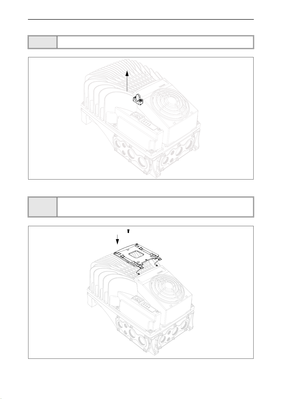
vacon • 80 Options
8.2.2 Installation
1
• Remove the HMI cap from the drive as shown in the Figure 51.
2
Figure 51. Disconnection of the HMI cap from the drive
• Install the keypad holder with a screw as shown in the Figure 52. The metal
sheets of the keypad holder have to be mounted under the fan holder as
shown in the following figures.
Figure 52. Installation of the keypad holder on the powerhead
Local contacts: https://www.danfoss.com/en/contact-us/contacts-list/

Options vacon • 81
3
• Connect the keypad to the drive and plug the cable on the HMI connector as
shown in the Figure 53 and in the Figure 54.
Figure 53. Mounting of the keypad
Figure 54. Keypad mounted onto the drive. Tighten the fixing screws of the cable connector (to
0.5 Nm or 4.5 lb-in) to the enclosure of the drive. This is to keep the high IP66 protection degree
of the drive.
Local contacts: https://www.danfoss.com/en/contact-us/contacts-list/

vacon • 82 Options
8.2.3 Wall-mounting
The keypad can be mounted on the wall in a convenient location by using the same keypad holder
and three screws provided with the keypad option kit.
•
Fix the keypad holder with three screws to the wall.
1
Figure 55. Fix the keypad holder with three screws to the wall
Local contacts: https://www.danfoss.com/en/contact-us/contacts-list/

Options vacon • 83
11863_00
2
Figure 56. Display holder dimensions for wall-mounting
• Connect and fix the cable to the enclosure of the drive and hold the keypad
to the wall.
Local contacts: https://www.danfoss.com/en/contact-us/contacts-list/

vacon • 84 Options
Figure 57. Keypad connected to the drive
Local contacts: https://www.danfoss.com/en/contact-us/contacts-list/

Options vacon • 85
9086.emf
FUNCT
Scroll menu up
Increase value
Scroll menu down
Decrease value
Move cursor left Move cursor right
Move backward in menu
Exit edit mode
Reset faults with long press
Change control place
Access control page
Change direction
Stop button Start button
Enter active level/item
Confirm selection
8.2.4 Graphical and Text keypad
There are two keypad types you can choose for your user interface: keypad with graphical display
and keypad with text segment display (text keypad).
The button section of the keypad is identical for both keypad types.
Figure 58. Keypad buttons
Local contacts: https://www.danfoss.com/en/contact-us/contacts-list/

vacon • 86 Options
Location field
Status field
(Parameter ID number
Main Menu
Quick Setup
( 17 )
Parameters
( 12 )
STOP READY I/O
ID: M1
( 5 )
Monitor
Activated group/item. Press OK to enter.
Number of items in the group
STOP/RUN
Status field
READY/NOT READY/FAULT
Control place:
PC/IO/KEYPAD/FIELDBUS
ALARM
and current menu location)
Direction
8.2.5 VACON® keypad with graphical display
The graphical keypad features an LCD display and 9 buttons.
8.2.5.1 Keypad display
The keypad display indicates the status of the motor and the drive and any irregularities in motor or
drive functions. On the display, the user sees information about
his present
location in the menu
structure and the item displayed.
8.2.5.2 Main menu
The data on the control keypad are arranged in menus and submenus. Use the Up and Down arrows
to move between the menus. Enter the group/item by pressing the OK button and
return
to the for-
mer level by pressing the Back/Reset button.
The
Location field
indicates your current location. The
Status field
gives information about the
present status of the drive. See Figure 59.
Figure 59. Main menu
8.2.5.3 Using the graphical keypad
Editing values
The selectable values can be accessed and edited in two different ways on the graphical keypad.
Parameters with one valid value
Typically, one parameter is set one value. The value is selected either from a list of values (see example below) or the parameter is given a numerical value from a defined range (e.g. 0.00...50.00
Hz).
Change value of a parameter following the procedure below:
1. Locate the parameter.
2. Enter the
3. Set new value with the arrow buttons up/down. You can also move from digit to digit with the
arrow buttons left/right if the value is numerical and then change the value with the arrow buttons up/down.
Edit
4. Confirm change with OK button or ignore change by returning to previous level with Back/
Reset button.
mode.
Local contacts: https://www.danfoss.com/en/contact-us/contacts-list/

Options vacon • 87
Start/Stop Setup
Rem Control Place
I/O Control
KeypadStopButton
Yes
Start Function
Ramping
STOP READY I/O
ID:172 M3.2.1
Edit
Help
Add to favorites
Rem Control Place
STOP READY I/O
ID: M3.2.1
Rem Control Place
STOP READY I/O
M3.2.1
I/O Control
FieldbusCTRL
Start/Stop Setup
Rem Control Place
I/O Control
KeypadStopButton
Yes
Start Function
Ramping
STOP REA DY I/O
ID:172 M3.2.1
Rem Control Place
STOP READY I/O
M3.2.1
I/O Control
FieldbusCTRL
OR:
OKOKOK
BACK
RESET
9257.emf
OK
9256.emf
...
O K
Symbol for checkbox selection
Figure 60. Typical editing of values on graphical keypad (text value)
Figure 61. Typical editing of values on graphical keypad (numerical value)
Parameters with checkbox selection
Some parameters allow selecting several values. Make a checkbox selection at each value you wish
to activate as instructed below.
Figure 62. Applying the checkbox value selection on graphical keypad
Local contacts: https://www.danfoss.com/en/contact-us/contacts-list/

vacon • 88 Options
Resetting fault
Instructions for how to reset a fault can be found in chapter 8.2.7.
Function button
The FUNCT button is used for four functions:
1. to quickly access the Control page,
2. to easily change between the Local (Keypad) and Remote control places,
3. to change the rotation direction and
4. to quickly edit a parameter value.
Control places
The
control place
place has its own parameter for selecting the frequency reference source. The
is always the keypad. The
is the source of control where the drive can be started and stopped. Every control
Local control place
Remote control place
is determined by parameter P3.2.1 (I/O or Field-
bus). The selected control place can be seen on the status bar of the keypad.
Remote control place
I/O A, I/O B and Fieldbus can be used as remote control places. I/O A and Fieldbus have the lowest
priority and can be chosen with parameter P3.2.1
(Rem Control Place)
. I/O B, again, can bypass the
remote control place selected with parameter P3.2.1 using a digital input. The digital input is selected with parameter P3.5.1.7
(I/O B Ctrl Force)
.
Local control
Keypad is always used as control place while in local control. Local control has higher priority than
remote control. Therefore, if, for example, bypassed by parameter P3.5.1.7 through digital input
while in
Remote
, the control place will still switch to Keypad if
Local
is selected. Switching between
Local and Remote Control can be done by pressing the FUNCT-button on the keypad or by using the
"Local/Remote" (ID211) parameter.
Changing control places
Change of control place from
1. Anywhere in the menu structure, push the
2. Push the
Arrow up
or the
Remote
Arrow down
to
Local
(keypad).
FUNCT
button.
button to select
Local/Remote
and confirm with the OK
button.
3. On the next display, select
4. The display will return to the same location as it was when the
Local
or
Remote
and again confirm with the OK button.
FUNCT
button was pushed. However, if the Remote control place was changed to Local (Keypad) you will be prompted for keypad reference.
Local contacts: https://www.danfoss.com/en/contact-us/contacts-list/

Options vacon • 89
Main Menu
Parameters
( 15 )
Diagnostics
STOP READY Keypad
ID: M1
( 7 )
Monitor
( 6 )
ID:
Choose action
STOP Ready Keypad
ID:1805
Local/Remote
Control page
Change direction
?
Remote
ID:
Local/Remote
STOP READY Keypad
ID:211
Remote
Local
Main Menu
Parameters
( 15 )
Diagnostics
STOP READY I/O
ID: M1
( 7 )
Monitor
( 6 )
FUNCT
O K
O K
9161.emf
Main Menu
Parameters
( 15 )
Diagnostics
STOP READY I/O
ID: M1
( 7 )
Monitor
( 6 )
ID:
Choose action
STOP Ready Keypad
ID:1805
Local/Remote
Control page
Change direction
STOP READY Keypad
( 6 )
Keypad Reference
0.00 Hz
Output Frequ ency
0.00Hz
Motor Curren t
0.00A
Motor Torque
0.00%
0.00%
Motor Power
ID:184
Keypad
0.00 Hz
Output Frequ ency
0.00Hz
Motor Curren t
0.00A
Motor Torque
0.00%
0.00%
Motor Power
STOP READY Keypad
( 6 )
ID:168
Keypad Reference
0.00 Hz
Output Frequ ency
0.00Hz
Motor Curren t
0.00A
Motor Torque
0.00%
0.00%
Motor Power
FUNCT
O K
O K
O K
9162.emf
Figure 63. Changing control places
Accessing the control page
The
Control page
is meant for easy operation and monitoring of the most essential values.
1. Anywhere in the menu structure, push the
2. Push the
Arrow up
or the
Arrow down
FUNCT
button.
button to select
Control page
and confirm with the OK
button.
3. The control page appears
If keypad control place and keypad reference are selected to be used you can set the
Reference
after having pressed the OK button. If other control places or reference values are
Keypad
used the display will show Frequency reference which is not editable. The other values on the
page are Multimonitoring values. You can choose which values appear here for monitoring.
Figure 64. Accessing Control page
Local contacts: https://www.danfoss.com/en/contact-us/contacts-list/
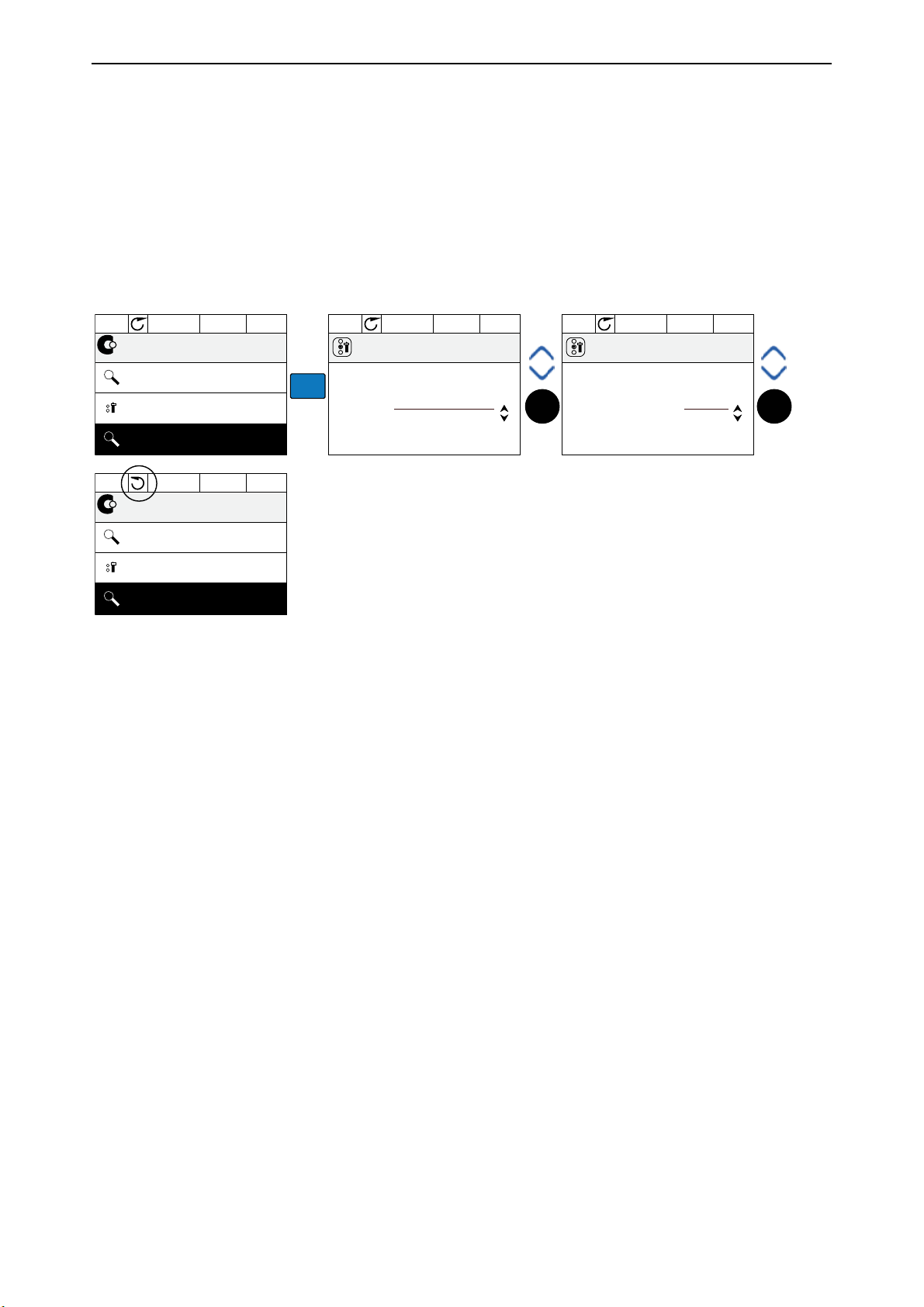
vacon • 90 Options
Main Menu
Parameters
( 15 )
Diagnostics
STOP READY I/O
ID: M1
( 7 )
Monitor
( 6 )
ID:
Choose action
RUN Ready Keypad
ID:1805
Local/Remote
Control page
Change direction
ID:
Choose action
RUN Ready Keypad
ID:1805
Forward
Reverse
Main Menu
Parameters
( 15 )
Diagnostics
STOP READY I/O
ID: M1
( 7 )
Monitor
( 6 )
FUNCT
O K O K
9163.ai
Changing direction
Rotation direction of the motor can quickly be changed by applying the FUNCT button.
ing direction
command is not visible in the menu unless the selected control place is
NOTE!
Local
Chang-
.
1. Anywhere in the menu structure, push the Funct button.
2. Push the Arrow up or the Arrow down button to select Change direction and confirm with the OK
button.
3. Then choose the direction you wish to run the motor to. The actual rotation direction is blinking.
Confirm with the OK button.
4. The rotation direction changes immediately and the arrow indication in the status field changes.
Figure 65. Changing direction
Quick edit
Through the
parameter’s ID number.
1. Anywhere in the menu structure, push the FUNCT button.
2. Push the Arrow up or the Arrow down buttons to select Quick Edit and confirm with the OK button.
3. Then enter the ID number of parameter or monitoring value you wish to access. Press OK button to confirm.
4. Requested Parameter/Monitoring value appears on the display (in editing/monitoring mode.)
Quick edit
functionality you can quickly access the desired parameter by entering the
Local contacts: https://www.danfoss.com/en/contact-us/contacts-list/

Options vacon • 91
STOP READY Keypad
Application selection
HVAC
User settings
Drive name
Drive
Parameter backup
( 3 )
ID: M6.5
STOP READY Keypad
Restore factory defaults
Parameter backup
Restore from keypad
Save to keypad
ID: M6.5.1
STOP READY Keypad
I/O and Hardware
( 8 )
Main Menu
Favourites
( 0 )
User settings
( 4 )
ID: M6
OK OK
Copying parameters
NOTE: This feature is available with graphical keypad only.
The parameter copy function can be used to copy parameters from one drive to another.
The parameters are first saved to the keypad, then the keypad is detached and connected to another
drive. Finally the parameters are downloaded to the new drive restoring them from the keypad.
Before any parameters can successfully be copied from one drive to another the drive has to be
stopped when the parameters are downloaded.
• First go into
eter backup
•
Restore factory defaults
User settings
menu and locate the
Parameter backup
submenu. In the
submenu, there are three possible functions to be selected:
will re-establish the parameter settings originally made at the fac-
Param-
tory.
• By selecting
•
Restore from keypad
Figure 66. Parameter copy
Save to keypad
will copy all parameters from keypad to a drive.
you can copy all parameters to the keypad.
NOTE: If the keypad is changed between drives of different sizes, the copied values of these parameters will not be used:
Motor nominal current (P3.1.1.4)
Motor nominal voltage (P3.1.1.1)
Motor nominal speed (P3.1.1.3)
Motor nominal power (P3.1.1.6)
Motor nominal frequency (P3.1.1.2)
Motor cos phi (P3.1.1.5)
Switching frequency (P3.1.2.3)
Motor current limit (P3.1.3.1)
Stall current limit (P3.9.3.2)
Stall time limit (P3.9.3.3)
Stall frequency (P3.9.3.4)
Maximum frequency (P3.3.1.2)
Local contacts: https://www.danfoss.com/en/contact-us/contacts-list/

vacon • 92 Options
( 6 )
Digital Inputs
Ctrl Signal 1 A
Ctrl Signal 1 B
STOP READY I/O
ID:403 M3.5.1.1
Ctrl Signal 2 A
( 6 )
Add to favorites
STOP READY I/O
ID:403 M3.5.1.1
Ctrl signal 1 A
Edit
Help
Start Signal 1 for control Place
I/O A. Start Signal 1
functionality chosen with I/O A
Logic in Start/Stop Setup Menu.
STOP READY I/O
Ctrl signal 1 A
ID:403 M3. 5.1.1
OK
OK
Basic Settings
Motor Nom Voltg
230.00 V
Motor Nom Speed
1430 rpm
STOP REA DY I/O
Motor Nom Freq
50.00 Hz
Edit
Help
Motor Nom Freq
STOP RE ADY I/O
Add to favorites
Motor Nom Freq
was added to
favorites. Press OK
to continue.
STOP RE ADY I/O
OK
OK
Help texts
The graphical keypad features instant help and information displays for various items.
All parameters offer an instant help display. Select Help and press the OK button.
Text information is also available for faults, alarms and the startup wizard.
Figure 67. Help text example
Adding item to favourites
You might need to refer to certain parameter values or other items often. Instead of locating them
one by one in the menu structure, you may want to add them to a folder called
Favorites
where they
can easily be reached.
To add an item to the Favorites.
Figure 68. Adding item to Favorites
Local contacts: https://www.danfoss.com/en/contact-us/contacts-list/

Options vacon • 93
Indicators:
Status
Indicators:
Alarm, Fault
Indicators:
Direction
Indicators:
Control place
Group or parameter
name
Menu location
8.2.6 VACON® keypad with text segment display
You can also choose a
Keypad with text segment display
(Text keypad) for your user interface. It
has mainly the same functionalities as the keypad with graphical display although some of these
are somewhat limited.
8.2.6.1 Keypad display
The keypad display indicates the status of the motor and the drive and any irregularities in motor or
drive functions. On the display, the user sees information about
his present
location in the menu
structure and the item displayed. If the text on the text line is too long to fit in the display, the text
will scroll from left to right to reveal the whole text string.
8.2.6.2 Main menu The data on the control keypad are arranged in menus and submenus. Use the Up and Down arrows
to move between the menus. Enter the group/item by pressing the OK button and
return
to the for-
mer level by pressing the Back/Reset button.
Local contacts: https://www.danfoss.com/en/contact-us/contacts-list/

vacon • 94 Options
BACK
RESET
OK
OK
OK
8.2.6.3 Using the keypad
Editing values
Change value of a parameter following the procedure below:
1. Locate the parameter.
2. Enter the Edit mode by pressing OK.
3. Set new value with the arrow buttons up/down. You can also move from digit to digit with the
arrow buttons left/right if the value is numerical and change then the value with the arrow buttons up/down.
4. Confirm change with OK button or ignore change by returning to previous level with Back/
Reset button.
Figure 69. Editing values
Resetting fault
Instructions for how to reset a fault can be found in chapter 8.2.7.
Function button
The FUNCT button is used for four functions:
1. to quickly access the Control page,
2. to easily change between the Local (Keypad) and Remote control places,
3. to change the rotation direction and
4. to quickly edit a parameter value.
Control places
The
control place
place has its own parameter for selecting the frequency reference source. The
is always the keypad. The
is the source of control where the drive can be started and stopped. Every control
Local control place
Remote control place
is determined by parameter P3.2.1 (I/O or Field-
bus). The selected control place can be seen on the status bar of the keypad.
Remote control place
I/O A, I/O B and Fieldbus can be used as remote control places. I/O A and Fieldbus have the lowest
priority and can be chosen with parameter P3.2.1
(Rem Control Place)
. I/O B, again, can bypass the
remote control place selected with parameter P3.2.1 using a digital input. The digital input is selected with parameter P3.5.1.7
(I/O B Ctrl Force)
.
Local control
Keypad is always used as control place while in local control. Local control has higher priority than
remote control. Therefore, if, for example, bypassed by parameter P3.5.1.7 through digital input
while in
Remote
, the control place will still switch to Keypad if
Local
is selected. Switching between
Local and Remote Control can be done by pressing the FUNCT-button on the keypad or by using the
"Local/Remote" (ID211) parameter.
Local contacts: https://www.danfoss.com/en/contact-us/contacts-list/

Options vacon • 95
FUNCT
OK OK
9169.emf
9170.emf
FUNCT
OK
O K
Changing control places
Change of control place from
Remote
to
Local
(keypad).
1. Anywhere in the menu structure, push the FUNCT button.
2. Using the arrow buttons, select Local/Remote and confirm with the OK button.
3. On the next display, select Local or Remote and again confirm with the OK button.
4. The display will return to the same location as it was when the
FUNCT
button was pushed.
However, if the Remote control place was changed to Local (Keypad) you will be prompted for
keypad reference.
Figure 70. Changing control places
Accessing the control page
The
Control page
is meant for easy operation and monitoring of the most essential values.
1. Anywhere in the menu structure, push the
2. Push the
Arrow up
or the
Arrow down
FUNCT
button.
button to select
Control page
and confirm with the OK
button.
3. The control page appears
If keypad control place and keypad reference are selected to be used you can set the
Reference
after having pressed the OK button. If other control places or reference values are
used the display will show Frequency reference which is not editable.
Figure 71. Accessing Control page
Keypad
Local contacts: https://www.danfoss.com/en/contact-us/contacts-list/

vacon • 96 Options
Changing direction
Rotation direction of the motor can quickly be changed by applying the FUNCT button.
ing direction
command is not visible in the menu unless the selected control place is
NOTE!
Local
Chang-
.
1. Anywhere in the menu structure, push the Funct button.
2. Push the Arrow up or the Arrow down button to select Change direction and confirm with the OK
button.
3. Then choose the direction you wish to run the motor to. The actual rotation direction is blinking.
Confirm with the OK button.
4. The rotation direction changes immediately and the arrow indication in the status field changes.
Quick edit
Through the
Quick edit
functionality you can quickly access the desired parameter by entering the
parameter’s ID number.
1. Anywhere in the menu structure, push the FUNCT button.
2. Push the Arrow up or the Arrow down buttons to select Quick Edit and confirm with the OK button.
3. Then enter the ID number of parameter or monitoring value you wish to access. Press OK button to confirm.
4. Requested Parameter/Monitoring value appears on the display (in editing/monitoring mode.)
Local contacts: https://www.danfoss.com/en/contact-us/contacts-list/

Options vacon • 97
Main Menu
( 5 )
Monitor
Parameters
( 12 )
Diagnostics
( 6 )
ID: M4
STOP READY I/O
Diagnostics
Active faults
( 0 )
Fault history
( 39 )
ID: M4.1
STOP READY I/O
Reset faults
Reset faults
Reset faults
Help
ID: M4.2
STOP READY I/O
OK
OK
OK
OK
8.2.7 Fault Tracing
When an unusual operating condition is detected by the AC drive control diagnostics, the drive initiates a notification visible, for example, on the keypad. The keypad will show the code, the name
and a short description of the fault or alarm.
The notifications vary in consequence and required action.
reset of the drive.
ning.
Info
may require resetting but do not affect the functioning of the drive.
Alarms
inform of unusual operating conditions but the drive will continue run-
Faults
make the drive stop and require
For some faults you can program different responses in the application. See parameter group Protections.
The fault can be reset with the
Reset button
on the control keypad or via the I/O terminal. The faults
are stored in the Fault history menu which can be browsed. The different fault codes you will find
in the table below.
NOTE: When contacting distributor or factory because of a fault condition, always write down all
texts and codes on the keypad display.
Fault appears
When a fault appears and the drive stops, examine the cause of fault, perform the actions advised
here and reset the fault as instructed below.
1. With a long (1 s) press on the
2. By entering the
Diagnostics
Reset
button on the keypad or
Menu (M4), entering
Reset faults
(M4.2) and selecting
Reset faults
parameter.
3. For keypad with LCD display only: By selecting value
Yes
for the parameter and clicking OK.
Figure 72. Diagnostic menu with graphical keypad
Figure 73. Diagnostic menu with text keypad
Local contacts: https://www.danfoss.com/en/contact-us/contacts-list/

vacon • 98 Options
Diagnostics
Active faults
( 0 )
Reset faults
Fault history
( 39 )
ID: M4.1
STOP READY I/O
!
!
!
Fault history
External Fault
Fault old
51
891384s
External Fault
Fault old
51
871061s
Device removed
Info old
39
862537s
ID:
STOP READY I/O
!
Device removed
ID: M4.3.3.2
Code 39
ID 380
State Info old
Date 7.12.2009
Time 04:46:33
Operating time 862537s
STOP READY I/O
OK
OK
OK
8.2.7.1 Fault History
In menu M4.3 Fault history you find the maximum number of 40 occurred faults. On each fault in the
memory you will also find additional information, see below.
Figure 74. Fault history menu with graphical keypad
Figure 75. Fault history menu with text keypad
Local contacts: https://www.danfoss.com/en/contact-us/contacts-list/
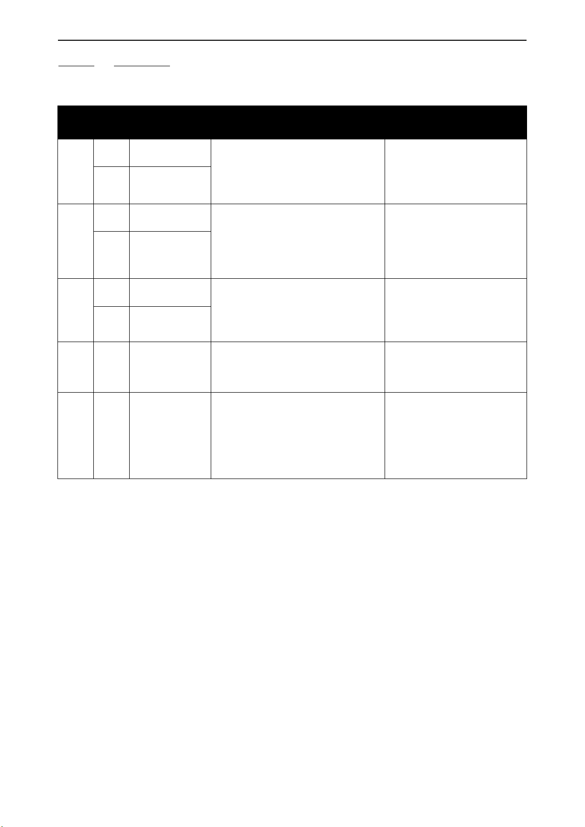
Options vacon • 99
8.2.7.2 Fault codes
Table 40. Fault codes and descriptions.
Fault
code
1
2
3
5 40
7 60
Fault
ID
1
2
10
11
20
21
Fault name Possible cause Remedy
Overcurrent
(hardware fault)
Overcurrent
(software fault)
Overvoltage
(hardware fault)
Overvoltage (software fault)
Earth fault (hardware fault)
Earth fault (software fault)
Charging switch
Saturation
AC drive has detected too high a current (>4*IH) in the motor cable:
• sudden heavy load increase
• short circuit in motor cables
• unsuitable motor
The DC-link voltage has exceeded the
limits defined.
• too short a deceleration time
• brake chopper is disabled
• high overvoltage spikes in supply
• Start/Stop sequence too fast
Current measurement has detected
that the sum of motor phase current is
not zero.
• insulation failure in cables or
motor
The charging switch is open, when the
START command has been given.
• faulty operation
• component failure
Various causes:
• defective component
• brake resistor short-circuit or
overload
Check loading.
Check motor.
Check cables and connections.
Make identification run.
Check ramp times.
Make deceleration time longer.
Use brake chopper or brake
resistor (available as options).
Activate overvoltage controller.
Check input voltage.
Check motor cables and motor.
Reset the fault and restart.
Should the fault re-occur, contact the distributor near to you.
Cannot be reset from keypad.
Switch off power.
DO NOT RE-CONNECT POWER!
Contact factory.
If this fault appears simultaneously with F1, check motor
cables and motor.
Local contacts: https://www.danfoss.com/en/contact-us/contacts-list/

vacon • 100 Options
Table 40. Fault codes and descriptions.
Fault
code
8
Fault
ID
600
601
602
603
604
605
606
607
608
609
610
Fault name Possible cause Remedy
Communication between control board
and power unit has failed.
Communication between control board
and power unit has interference, but it
is still working.
Reset the fault and restart.
Should the fault re-occur, contact the distributor near to you.
Update software. Should the
fault re-occur, contact the distributor near to you.
Update power unit software.
Should the fault re-occur, contact the distributor near to you.
Reset the fault and restart.
Should the fault re-occur, contact the distributor near to you.
System fault
Watchdog has reset the CPU
Voltage of auxiliary power in power unit
is too low.
Phase fault: Voltage of an output phase
does not follow the reference
CPLD has faulted but there is no
detailed information about the fault
Control and power unit software are
incompatible
Software version cannot be read. There
is no software in power unit.
CPU overload. Some part of the software (for example application) has
caused an overload situation. The
source of fault has been suspended
Memory access has failed. For example, retain variables could not be
restored.
Necessary device properties cannot be
read.
614
647
648
649
80
9
81
10 91
Configuration error.
Software error
Invalid function block used in application. System software and application
are not compatible.
Resource overload.
Error when loading parameter initial
values.
Error when restoring parameters.
Error when saving parameters.
Undervoltage
(fault)
DC-link voltage is under the voltage
limits defined.
• most probable cause: too low a
supply voltage
• AC drive internal fault
Undervoltage
(alarm)
• defect input fuse
• external charge switch not
closed
NOTE!
This fault is activated only if the
drive is in Run state.
Input phase Input line phase is missing.
Update software. Should the
fault re-occur, contact the distributor near to you.
In case of temporary supply
voltage break reset the fault
and restart the AC drive. Check
the supply voltage. If it is adequate, an internal failure has
occurred.
Contact the distributor near to
you.
Check supply voltage, fuses and
cable.
Local contacts: https://www.danfoss.com/en/contact-us/contacts-list/
 Loading...