

Danfoss vacon 100 industrial, vacon 100 flow, vacon 100 hvac, vacon 100 x Installation guide

vacon
®
100 industrial
vacon
vacon
®
100 flow
®
100 hvac
vacon® 100 x
ac drives
integrated bacnet
installation manual


vacon • 1
Table of Contents
Document: DPD00091D
Version release date: 8.12.16
1. Safety................................................................................................................2
1.1 Danger.................................................................................................................................2
1.2 Warnings .............................................................................................................................3
1.3 Earthing and earth fault protection ....................................................................................4
2. BACnet - general info .......................................................................................5
3. BACnet technical data.......................................................................................6
3.1 BACnet MS/TP protocol ......................................................................................................6
3.2 BACnet IP protocol..............................................................................................................6
3.3 ACD (Address Conflict Detection).......................................................................................6
4. Programming....................................................................................................7
4.1 BACnet MS/TP parameters and monitoring values ...........................................................8
4.2 BACnet IP parameters and monitoring values...................................................................9
4.2.1 Ethernet common settings .................................................................................................9
4.2.2 BACnet IP settings ..............................................................................................................9
4.3 BACnet MS/TP parameter descriptions ...........................................................................11
4.3.1 BACnet MS/TP Parameters ..............................................................................................11
4.3.2 BACnet MS/TP monitoring values ....................................................................................12
4.4 BACnet IP parameter descriptions...................................................................................13
4.4.1 Ethernet common settings ...............................................................................................13
4.4.2 BACnet IP settings ............................................................................................................14
4.4.3 BACnet IP monitoring values............................................................................................15
5. Installation......................................................................................................16
5.1 VACON® 100 family AC drive............................................................................................16
5.1.1 Prepare for use through Ethernet....................................................................................17
5.1.2 Prepare for use through RS485........................................................................................20
5.2 Installation in VACON® 100 X...........................................................................................24
5.2.1 Prepare for use through Ethernet....................................................................................24
5.2.2 Prepare for use through RS485........................................................................................25
6. Communications .............................................................................................27
6.1 Device Object.....................................................................................................................27
6.2 Object types and properties supported ............................................................................27
6.2.1 Binary Value Object...........................................................................................................28
6.2.2 Analogue Value Object ......................................................................................................29
6.3 Control word bits...............................................................................................................31
6.4 Status word bits ................................................................................................................31
6.5 COV functionality ...............................................................................................................31
6.6 Processdata mapping in drive application .......................................................................32
7. Fault tracing ...................................................................................................33
7.1 Typical fault conditions .....................................................................................................33
7.2 Other fault conditions .......................................................................................................34
8. Quick setup .....................................................................................................36
9. Annex - Protocol implementation conformance statement ............................37
Local contacts: http://drives.danfoss.com/danfoss-drives/local-contacts/
vacon • 2 Safety
9000.emf
13006.emf
9001.emf
9000.emf
9000.emf
9000.emf
9000.emf
9000.emf
9000.emf
1. SAFETY
This manual contains clearly marked cautions and warnings that are intended for your personal
safety and to avoid any unintentional damage to the product or connected appliances.
Please read the information included in cautions and warnings carefully.
The cautions and warnings are marked as follows:
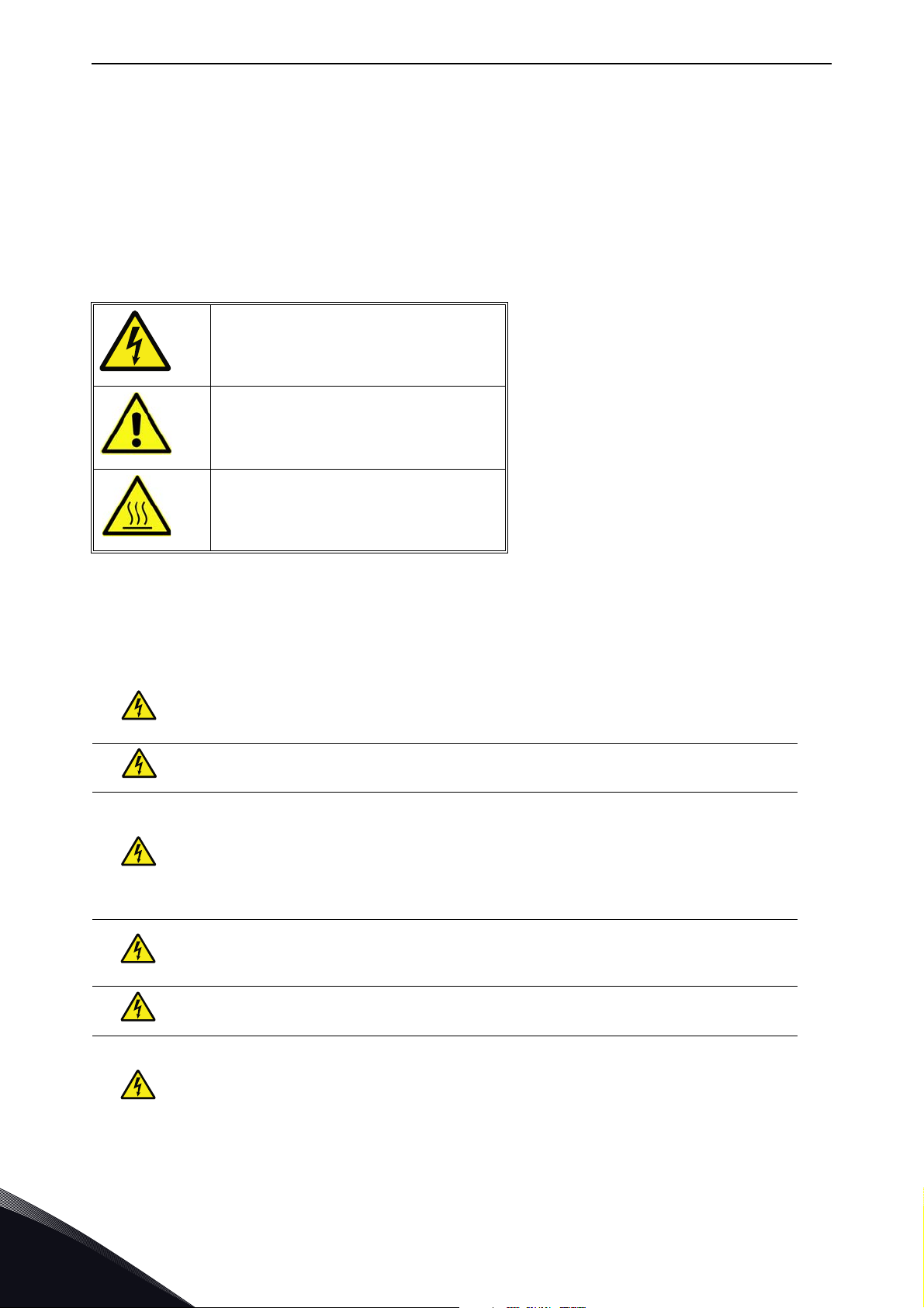
Table 1. Warning signs
= DANGER! Dangerous voltage
= WARNING or CAUTION
= Caution! Hot surface
1.1 Danger
The components of the power unit are live when the drive is connected to mains
potential. Coming into contact with this voltage is extremely dangerous and may
cause death or severe injury.
The motor terminals U, V, W and the brake resistor terminals are live when the
AC drive is connected to mains, even if the motor is not running.
After disconnecting the AC drive from the mains, wait until the indicators on the
keypad go out (if no keypad is attached, see the indicators on the cover). Wait 5
more minutes before doing any work on the connections of the drive. Do not open
the cover before this time has expired. After expiration of this time, use a measuring equipment to absolutely ensure that no
absence of voltage before starting any electrical work!
The control I/O-terminals are isolated from the mains potential. However, the
relay outputs and other I/O-terminals may have a dangerous control voltage
present even when the AC drive is disconnected from mains.
voltage is present.
Always ensure
Before connecting the AC drive to mains make sure that the front and cable covers of the drive are closed.
During a ramp stop (see the Application Manual), the motor is still generating
voltage to the drive. Therefore, do not touch the components of the AC drive
before the motor has completely stopped. Wait until the indicators on the keypad
go out (if no keypad is attached, see the indicators on the cover). Wait additional 5
minutes before starting any work on the drive.
Local contacts: http://drives.danfoss.com/danfoss-drives/local-contacts/
1
Safety vacon • 3
13006.emf
13006.emf
13006.emf
13006.emf
13006.emf
13006.emf
13006.emf
13006.emf
13006.emf
13006.emf
13006.emf
1.2 Warnings
The AC drive is meant for fixed installations only.
Do not perform any measurements when the AC drive is connected to the mains.
The earth leakage current of the AC drives exceeds 3.5mA AC. According to stan-
dard EN61800-5-1, a reinforced protective ground connection must be ensured.
See Chapter 1.3.
If the AC drive is used as a part of a machine, the machine manufacturer is
responsible for providing the machine with a supply disconnecting device (EN
60204-1).
Only spare parts delivered by VACON
®
can be used.
At power-up, power break or fault reset the motor will start immediately if the
start signal is active, unless the pulse control for
Start/Stop logic has been selected
Furthermore, the I/O functionalities (including start inputs) may change if parameters, applications or software are changed. Disconnect, therefore, the motor if
an unexpected start can cause danger.
The motor starts automatically after automatic fault reset if the auto restart
function is activated. See the Application Manual for more detailed information.
Prior to measurements on the motor or the motor cable, disconnect the motor
cable from the AC drive.
Do not touch the components on the circuit boards. Static voltage discharge may
damage the components.
Check that the EMC level of the AC drive corresponds to the requirements of your
supply network.
Wear protective gloves when you do mounting, cabling or maintenance operations. There can be sharp edges in the AC drive that can cause cuts.
.
Local contacts: http://drives.danfoss.com/danfoss-drives/local-contacts/
1
vacon • 4 Safety
13006.emf 13006.emf
1.3 Earthing and earth fault protection
CAUTION!
The AC drive must always be earthed with an earthing conductor connected to the earthing terminal
marked with .
The earth leakage current of the drive exceeds 3.5mA AC. According to EN61800-5-1, one or more
of the following conditions for the associated protective circuit must be satisfied:
a) The protective conductor must have a cross-sectional area of at least 10 mm2 Cu or 16
mm2 Al, through its total run.
b) Where the protective conductor has a cross-sectional area of less than 10 mm2 Cu or 16
mm2 Al, a second protective conductor of at least the same cross-sectional area must be
provided up to a point where the protective conductor has a cross-sectional area not less
than 10 mm2 Cu or 16 mm2 Al.
c) Automatic disconnection of the supply in case of loss of continuity of the protective conduc-
tor.
The cross-sectional area of every protective earthing conductor which does not form part of the
supply cable or cable enclosure must, in any case, be not less than:
-2.5mm
-4mm
2
if mechanical protection is provided or
2
if mechanical protection is not provided.
The earth fault protection inside the AC drive protects only the drive itself against earth faults in the
motor or the motor cable. It is not intended for personal safety.
Due to the high capacitive currents present in the AC drive, fault current protective switches may
not function properly.
Do not perform any voltage withstand tests on any part of the AC drive. There is
a certain procedure according to which the tests must be performed. Ignoring
this procedure may result in damaged product.
NOTE! You can download the English and French product manuals with applicable safety,
warning and caution information from
http://drives.danfoss.com/knowledge-center/technical-documentation/.
REMARQUE Vous pouvez télécharger les versions anglaise et française des manuels produit
contenant l’ensemble des informations de sécurité, avertissements et mises en garde
applicables sur le site http://drives.danfoss.com/knowledge-center/technical-documentation/
.
Local contacts: http://drives.danfoss.com/danfoss-drives/local-contacts/
1
BACnet - general info vacon • 5
BACnet IP - Ethernet
Ethernet to
MS/TP
Router
Switch
BACnet IP
BACnet MS/TP
7061.emf
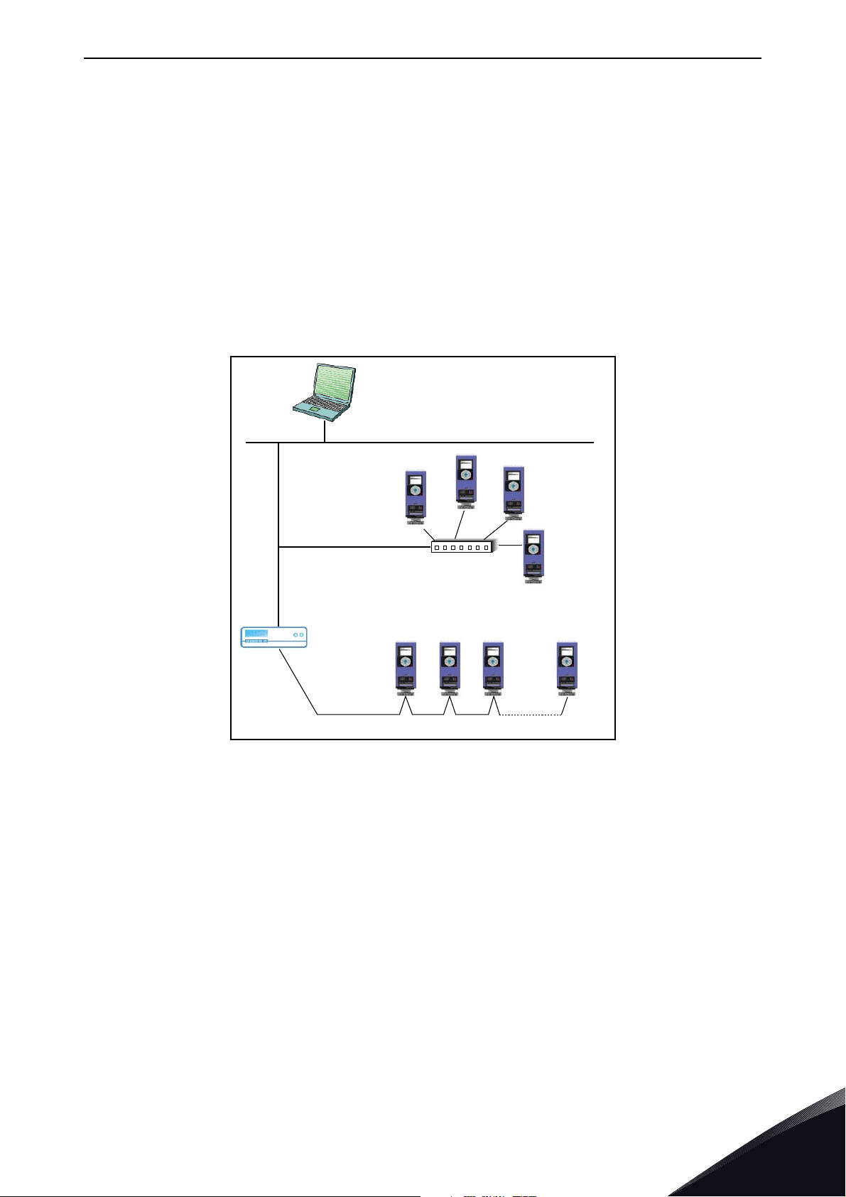
2. BACNET - GENERAL INFO
BACnet stands for ‘Building Automation and Control Networks’. It is the common name for the
communication standard ISO 16484-5 which defines the methods and the protocol for cooperating
building automation devices to communicate. Devices can be designed to operate using BACnet
communication protocol as well as utilising BACnet protocol to communicate between systems.
BACnet is an internationally accepted protocol for building automation (e.g. lightning control, air
conditioning and heating automation) and control over a communications network.
BACnet provides a method by which computer-based control equipment, from different
manufacturers can work together, or 'interoperate'. For this to be achieved, components must be
able to exchange and understand BACnet data messages.
®
Your VACON
100 family AC drive is equipped with BACnet support as standard.
Figure 1. Principal example diagram of BACnet
®
If you need to contact VACON
problem together with the Drive Info File taken with VACON
download the Service Information file with the VACON
service in problems related to BACnet, send a description of the
®
®
Live to your local support. You can
Live tool. In BACnet/IP networks, also send
a log file captured with the Wireshark tool that contains the error situation.
Local contacts: http://drives.danfoss.com/danfoss-drives/local-contacts/
2

vacon • 6 BACnet technical data
3. BACNET TECHNICAL DATA
3.1 BACnet MS/TP protocol
Table 2.
Interface RS-485
Data transfer method RS-485 MS/TP, half-duplex
Transfer cable
Connections and
communications
Connector
Electrical isolation Functional
BACnet MS/TP
Baud rate
3.2 BACnet IP protocol
Interface 100BaseTX, IEEE 802.3 compatible
Data transfer method Ethernet half/full -duplex
Data transfer speed 10/100 MBit/s, autosensing
Connections and
communications
Protocol BACnet over UDP/IP
Connector Shielded RJ45 connector.
Cable type CAT5e STP
STP (Shielded Twisted Pair), type
Belden 9841 or similar
2.5 mm
As described in ANSI/ASHRAE Standards 135-2010 Ver.1 Rev.12
9600, 19200, 38400 and 76800
baud(supports autobaud detection)
Table 3.
2
BACnet IP
IP address mode Selectable: Static or DHCP
As described in ANSI/ASHRAE Standards 135-2010 Ver.1 Rev.12
3.3 ACD (Address Conflict Detection)
The VACON® 100 family AC drives implement the ACD algorithm (IETF RFC 5227).
The ACD algorithm tries to actively detect if the IP address configured to this device is been used by
another device in the same network. To accomplish this, ACD sends four ARP request packets when
the device's Ethernet interface goes up or when its IP address changes. ACD prevents the use of the
Ethernet interface until the ARP probing finishes. This delays the startup of fieldbus protocols about
one second. During the delay or after it, the ACD passively checks incoming ARP messages for use
of the device's IP address.
If another device with the same IP address is detected, the ACD will try to defend its IP address with
a single ARP message. If the other device with the same IP address also supports ACD, it should
stop using the address. If not, the ACD will close the Ethernet connection and indicate the situation
with an Alarm. This is done according the "DefendWithPolicyB". Acknowledging of the Alarm is not
possible if the problem is active. ACD opens Ethernet connection if the other device with the same
IP address disappears from the network. Alarm can be acknowledged after this. Other policies are
not supported. If the fieldbus protocol has been active, a fieldbus fault may be activated (depends
on the fieldbus and drive application configuration).
3
Local contacts: http://drives.danfoss.com/danfoss-drives/local-contacts/

Programming vacon • 7
4. PROGRAMMING
You will find basic information on how to use the control keypad in the Application Manual of your
VACON
Below you will find some examples of navigation paths to the fieldbus parameters.
®
100 family AC drive.
Table 4.
1. First ensure that the right fieldbus protocol is selected.
Activating BACnet MSTP (P5.8.1.1)
Main Menu > I/O and Hardware > RS-485 > Common settings > Protocol > BACnet MSTP <
Activating BACnet IP (P5.9.3.1.4)
Main Menu > I/O and Hardware > Ethernet > Bacnet IP > Protocol in
use > Yes <
2. Select
3. Activate Remote control.
4. Select controlling fieldbus
5. Set up Protocol Parameters.
‘Fieldbus control’ as the Remote Control Place.
Control Place (P3.2.1)
Main Menu > Parameters > Start/Stop Setup > Rem Control Place >
FieldbusCTRL <
Local/Remote (P3.2.2)
Main Menu > Parameters > Start/Stop Setup > Local/Remote >
Remote <
Controlling Fieldbus (P5.13.1)
Main Menu > I/O and Hardware > Fieldbus General > Controlling
Fieldbus > Automatic/BACnet IP/RS-485 <
BACnet MS/TP parameters see Chapter 4.1
BACnet IP parameters see Chapter 4.2
Local contacts: http://drives.danfoss.com/danfoss-drives/local-contacts/
4

vacon • 8 Programming
4.1 BACnet MS/TP parameters and monitoring values
Table 5. Parameters related with BACnet used through MS/TP
Code Parameter Min Max Default ID Description
Communication speed
1 = 9600
P5.8.3.1.1 Baud rate 9600 76800 9600 2392
P5.8.3.1.2 MAC Address 1 127 1 2331 BACnet device MAC address
P5.8.3.1.3 Instance number 0 4194304 automatic 2332
P5.8.3.1.4 MaxMaster 1 127 127 2561
P5.8.3.1.5
P5.8.3.1.6 MaxAPDUcycle 0 65535 0 2554
Communication
time-out
0 65535 10 2333
2 = 19200
3 = 38400
4 = 76800
5 = Autobaud
Device Object's instance number.
0 = Automatically
generated from the last 22 bit from
Ethernet MAC address.
Max Master parameter of device object.
This can be used to reduce poll for
master cycles.
Defines the number of seconds after
which a communication timeout is indicated after a communication break.
Value 0 disables this feature.
Defines the number of seconds after
which the next application level message is shown after a communication
break. Value 0 disables this feature.
Table 6. Monitoring values
Code Parameter Min Max ID Description
V5.8.3.2.1 Fieldbus protocol status INITIALIZING INACTIVE 2393 See Table 11
V5.8.3.2.2 Communication status 0.0 99.999 2394
V5.8.3.2.3 Actual instance 0 4194304 2395
See fault codes
V5.8.3.2.4 Last fault
V5.8.3.2.5 UartDBG 0.0.0
V5.8.3.2.6 ActiveCOVcount 0 20 2558 Number of active COV subscriptions
V5.8.3.2.7 Control Word 0 FFFFFFFF 2397 Control word monitor value
V5.8.3.2.8 Status Word 0 FFFFFFFF 2398 Status word monitor value
(table Table 10) 2396 Information about the latest fault detected.
32767.
32767.
32767
2559
Counter for failed and good messages
failed msg's <-> good msg's
Actual instance in use. If the instance
parameter is 0, the generated instance
number shows here.
Uart error counters in the following order:
framing errors.
overrun errors.
parity errors.
4
Local contacts: http://drives.danfoss.com/danfoss-drives/local-contacts/

Programming vacon • 9
4.2 BACnet IP parameters and monitoring values
4.2.1 Ethernet common settings
Table 7. Eth e r net Common S ettings
Code Parameter Min Max Default ID Description
P5.9.1.1 IP address mode 0 1 1 2482
P5.9.1.2
P5.9.1.2.1 IP address 1.0.0.0 223.255.255.255 192.168.0.10 2529
P5.9.1.2.2 Subnet mask 0.0.0.0 255.255.255.255 255.255.0.0 2530
P5.9.1.2.3 Default gateway 0.0.0.0 255.255.255.255 192.168.0.1 2531
P5.9.1.3 IP address - - 0 2483 IP address in use
P5.9.1.4 Subnet mask - - 0 2484 Subnet mask in use
P5.9.1.5 Default gateway - - 0 2485 Default gateway in use
P5.9.1.6 MAC address - - - 2486 MAC address
Duplicate IP Detec-
tion
0 1 1 2569
0 = Fixed IP
1 = DHCP with AutoIP
This is setting for enabling ACD
(See Chapter 3.3). When disabled
drive does not check for or react to
address conflict situation.
0 = Disabled
1 = Enabled
The parameter is in use if P5.9.1.1
= 0/Fixed IP
The parameter is in use if P5.9.1.1
= 0/Fixed IP
The parameter is in use if P5.9.1.1
= 0/Fixed IP
4.2.2 BACnet IP settings
Table 8. Parameters related with BACnet used through Ethernet
Code Parameter Min Max Default ID Description
Device Object’s instance
P5.9.3.1.1 Instance number 0 4194304 automatic 2406
P5.9.3.1.2 BACnet Port Number 47808 47823 47808 2538
P5.9.3.1.2 Communication time-out 0 65535 10 2407
P5.9.3.1.3 Protocol in use 0 1 0 2408 Activates BACnet IP protocol
P5.9.3.1.4 ForeignDevice Sub menu for Foreign Device setting
P5.9.3.1.5.1 ForeignDevice No Yes No 2555
P5.9.3.1.5.2 BBMD IP 192.168.0.1 2409
P5.9.3.1.5.3 BBMD Port 47808 47823 47808 2410 BBMD port number
P5.9.3.1.5.4 RegistrationInterval 1 65535 10 2411
0 = Automatically generated from
the last 22 bit from the Ethernet
MAC address.
UDP port for BACnet IP communication.
Defines the number of seconds
after which a communication
timeout is indicated after a communication break. Value 0 disables this feature.
Activates foreign device registration
IP address of BBMD device to
send registration
Registration interval to keep a
live connection to BBMD.
NOTE! Registration message
TTL is twice as long as this time.
Local contacts: http://drives.danfoss.com/danfoss-drives/local-contacts/
4

vacon • 10 Programming
Table 9. Monitoring values
Code Parameter Min Max ID Description
V5.9.3.2.1
V5.9.3.2.2
V5.9.3.2.3 Actual instance 0 4194304 2414
V5.9.3.2.4 Last fault
V5.9.3.2.5 ActiveCOVcount 0 20 2557 Number of active COV subscriptions
V5.9.3.2.6 Control Word 0 FFFFFFFF 2397 Control word monitor value
V5.9.3.2.7 Status Word 0 FFFFFFFF 2398 Status word monitor value
Fieldbus protocol
status
Communication
status
INITIALIZING INACTIVE 2412 See Table 11
0.0 99.999 2413
See fault codes
(Table 10)
2556 The fault code of the latest fault detected.
Counter for failed and good messages
failed msg's <-> good msg's
Actual instance is use. In case instance parameter is zero you can see here generated
instance number
Table 10. Fault Code values
Fault
Number
0 No fault No fault detected since the last power-up.
1 Connection timeout Timeout occurred in communication.
2 MAC address Duplicate MAC address detected.
3 Autobaud Error Error during baudrate detection.
4 Ethernet link lost Ethernet cable disconnected during communication.
Fault Text Description
Table 11. Fieldbus Protocol Status
Value Tex t Description
1 INITIALIZING Protocol is starting
2 STOPPED Protocol is stopped
3OPERATIONALCommunicating
4 FAULTED Timeout/APDU time expired
5 INACTIVE No communication
4
Local contacts: http://drives.danfoss.com/danfoss-drives/local-contacts/

Programming vacon • 11
4.3 BACnet MS/TP parameter descriptions
4.3.1 BACnet MS/TP Parameters
P5.8.3.1.1 BAUD RATE
Select the communication speed for the network. The default value is 9600 baud. If Autobauding is
selected, the node will detect the baudrate. There must be at least one device in the bus to select
the baud rate and to start token transmitting. When the baudrate is detected, it is saved into this
parameter.
NOTE! Autobauding is disabled after baudrate is detected.
P5.8.3.1.2 MAC ADDRESS
The parameters of every device must be set before connecting to the bus. Especially the
parameters
The first parameter, BACnet MAC (Medium Access Control) address, must be unique on the
network to which it is connected. The same MAC address may be used on a device on another
network within the internetwork.
Addresses 128-254 are reserved for slaves. Addresses 1-127 are valid for both masters and slaves.
The portion of the address space that is actually used for masters in a particular installation is
determined by the value of the Max_Master property of the Device object.
MAC address and Baud rate must be the same as in the master’s configuration.
It is recommended that MAC address 0 be reserved for use by the MS/TP router. 255 is reserved for
broadcasts.
P5.8.3.1.3 INSTANCE NUMBER
The Device Object's Instance number must be unique across the entire BACnet internetwork
because it is used to uniquely identify the BACnet devices. It may be used to conveniently identify
the BACnet device from other devices during installation.
If 0 (default) is selected, the Device Instance number is generated from the last 22 bit of the
Ethernet MAC address. This unique number is then shown in the Monitor menu (actual instance).
P5.8.3.1.4 MAXMASTER
This parameter defines the last possible master on the network segment. Each master node is
responsible for searching new devices from network using the ‘poll for master’ messages. The
nodes are searched up to MAC address defined by MaxMaster parameter.
This parameter affects the cycle time of the token. We recommend to use the highest MAC address
value in the network for this parameter.
P5.8.3.1.5 COMMUNICATION TIMEOUT
The BACnet MS/TP indicates timeout error if the node is not receiving a token within time defined
by this parameter. It can be used to detect communication loss to other nodes. Time unit is
seconds.
NOTE! Application parameter P3.9.1.6 (ID 733) can be use to define action for communication
timeout.
Local contacts: http://drives.danfoss.com/danfoss-drives/local-contacts/
4

vacon • 12 Programming
P5.8.3.1.6 MAXAPDUCYCLE
This parameter defines the maximum time in seconds between APDU messages addressed to this
node. The APDU messages are Application layer messages, for example, 'ReadParameter' and
'Write Parameter' messages. This can be used to detect communication loss to the controlling
node.
NOTE! The application parameter P3.9.1.6 (ID 733) can be used to define the action for
communication timeout.
4.3.2 BACnet MS/TP monitoring values
V5.8.3.2.1 FIELDBUS PROTOCOL STATUS
Fieldbus Protocol Status tells the status of the protocol.
V5.8.3.2.2 COMMUNICATION STATUS
The Communication status shows how many error and how many good messages the AC drive has
received. The Communication status includes a common error counter that counts CRC and parity
errors and a counter for good messages.
Only messages to the current slave in use are counted in the good messages, not MS/TP token
packages.
Table 12 .
Good messages
0…999
Number of messages received without errors
Bad Frames
0…99
V5.8.3.2.3 ACTUAL INSTANCE NUMBER
Number of messages received with
errors
Shows the actual instance number.
V5.8.3.2.4 LAST FAULT
This monitor value consist of text string that gives extra information about the fault condition. Can
be used to track the reason for communication timeout. See Table 10.
V5.8.3.2.5 UARTDBG
This is advanced debug information from RS-485 uart module. It shows parity, framing and overrun
errors occurred while receiving the MSTP messages.
4
V5.8.3.2.6 ACTIVECOVCOUNT
This shows the number of active COV subscriptions on the device.
V5.8.3.2.7 CONTROL WORD
Shows control word that is written by BACnet MS/TP into drive application. This is shown in panel
as hexadecimal format.
V5.8.3.2.8 STATUS WORD
Shows control word that is written by BACnet MS/TP into drive application. This is shown in panel
as hexadecimal format.
Local contacts: http://drives.danfoss.com/danfoss-drives/local-contacts/

Programming vacon • 13
4.4 BACnet IP parameter descriptions
4.4.1 Ethernet common settings
P5.9.1.1 IP ADDRESS MODE
Selectable alternatives are DHCP (Dynamic Host Configuration Protocol) and Fixed.
DHCP protocol gives IP addresses to new devices connecting to local network. This address is valid
for a certain period of time.
A fixed IP address is specified manually and it does not change.
If the fixed IP mode is selected, the addresses defined in the 'Fixed IP' menu come into use. The
default Fixed IP is shown below.
IP: 192.168.0.10
Subnet mask: 255.255.0.0
Default gateway: 0.0.0.0
P5.9.1.3 IP ADDRESS
An IP address is a series of numbers (like above) specific to the device connected to the Internet.
P5.9.1.4 SUBNET MASK
The network mask marks all the bits of an IP address for the identification of the network and the
subnetwork.
P5.9.1.5 DEFAULT GATEWAY
Gateway address is the IP address of a network point that acts as an entrance to another network.
This needs to be defined if the device communicates with nodes on different networks, for example,
if the 'Foreign Device' functionality is active.
P5.9.1.6 MAC ADDRESS
The Ethernet MAC address of the control board.
MAC address (Media Access Control) is a unique address given to each network host.
Local contacts: http://drives.danfoss.com/danfoss-drives/local-contacts/
4

vacon • 14 Programming
4.4.2 BACnet IP settings
P5.9.3.1.1 INSTANCE NUMBER
Similar to BACnet MS/TP device object instance number (see Chapter 4.3.1).
P5.9.3.1.2 BACNET PORT NUMBER
The UDP port for the BACnet IP communication.
P5.9.3.1.3 COMMUNICATION TIME-OUT
Defines the number of seconds after a timeout is indicated after a communication break or
disconnected ethernet link. Value 0 disables communication and link supervision.
NOTE! The Application parameter P3.9.1.6 (ID 733) can be used to define the action for
communication timeout.
P5.9.3.1.4 PROTOCOL IN USE
BACnet/IP protocol can be enabled and disabled with this parameter. When the parameter value is
set to "1" the BACnet/IP protocol is enabled and disabled when set to "0".
P5.9.3.1.5 FOREIGNDEVICE
The foreign device settings are located under this submenu. The foreign device feature is used
when the device is located in a different network than the BBMD. A normal router does not send
broadcast messages between different networks. The 'Foreign device' feature solves this problem
by establishing a connection to the BBMD with unicast messages. All broadcast messages are
forwarded to a BBMD device that takes care of receiving and transmitting broadcast messages in
both directions for all foreign devices.
P5.9.3.1.5.1 FOREIGNDEVICE
If this parameter is set to value 'Yes', the foreign device registration becomes active.
P5.9.3.1.5.2 BBMD IP
The IP address of the BACnet IP Broadcast Management Device.
P5.9.3.1.5.3 BBMD PORT
The BBMD Port number.
P5.9.3.1.5.4 REGISTRATIONINTERVAL
The registration interval to keep a live connection to the BBMD. Unit is seconds.
NOTE! The Registration TTL is twice as long as this time.
4
Local contacts: http://drives.danfoss.com/danfoss-drives/local-contacts/

Programming vacon • 15
4.4.3 BACnet IP monitoring values
V5.9.3.2.1 FIELDBUS PROTOCOL STATUS
Fieldbus Protocol Status tells the status of the protocol.
V5.9.3.2.2 COMMUNICATION STATUS
The Communication status shows how many error and how many good messages the AC drive has
received. The Communication status includes a common error counter that counts CRC and parity
errors and a counter for good messages.
Table 13 .
Good messages
0…999
Number of messages received without errors
Bad Frames
0…99
V5.9.3.2.3 ACTUAL INSTANCE NUMBER
Number of messages received with
errors
The Device Object's actual instance number. This monitoring value is needed when value 0 is
written to parameter P5.8.3.1.1.
V5.9.3.2.4 LAST FAULT
This monitor value contains a text string that gives extra information about the fault condition. Can
be used to track reason for communication timeout. See Table 10.
V5.9.3.2.5 ACTIVECOVCOUNT
This shows the number of active COV subscriptions on the device.
V5.9.3.2.6 CONTROL WORD
Shows control word that is written by BACnet IP into drive application. This is shown in panel as
hexadecimal format.
V5.9.3.2.7 STATUS WORD
Shows status word that is written by drive application to BACnet IP. This is shown in panel as
hexadecimal format.
Local contacts: http://drives.danfoss.com/danfoss-drives/local-contacts/
4

vacon • 16 Installation
M4x55
9174.emf
9000.emf
5. INSTALLATION
5.1 VACON® 100 family AC drive
Open the cover of the AC drive.
1
2
The relay outputs and other I/O-terminals may have a dangerous control voltage
present even when the AC drive is disconnected from mains.
Open the inner cover of the drive.
5
Local contacts: http://drives.danfoss.com/danfoss-drives/local-contacts/

Installation vacon • 17
Ethernet
cable
9316.emf
5.1.1 Prepare for use through Ethernet
Connect the Ethernet cable (see specification in Chapter 3.2) to its terminal as
shown in figure below.
3
Local contacts: http://drives.danfoss.com/danfoss-drives/local-contacts/
5

vacon • 18 Installation
9068.emf
Protection class IP21: Cut free the opening on the AC drive cover for the Ethernet cable.
Protection class IP54: Cut the rubber grommets open to slide the cables
through. Should the grommets fold in while inserting the cable, just draw the
cable back a bit to straighten the grommets up. Do not cut the grommet openings wider than what is necessary for the cables you are using.
NOTE! To meet the requirements of the enclosure class IP54, the connection
between the grommet and the cable must be tight. Therefore, lead the first bit of
the cable out of the grommet straight before letting it bend. If this is not possible, the tightness of the connection must be ensured with insulation tape or a
cable tie.
4
5
Local contacts: http://drives.danfoss.com/danfoss-drives/local-contacts/

Installation vacon • 19
IP54
9265.emf
IP21
Ethernet
cable
Remount the AC drive cover.
NOTE! When planning the cable runs, remember to keep the distance between
the Ethernet cable and the motor cable at a minimum of 30 cm.
5
Local contacts: http://drives.danfoss.com/danfoss-drives/local-contacts/
5

vacon • 20 Installation
9189.emf
10
5
1
5
m
m
9188.emf
5.1.2 Prepare for use through RS485
Strip about 15 mm of the RS485 cable (see specification in Chapter 3.1) and cut
off the grey cable shield. Remember to do this for both bus cables (except for the
last device).
Leave no more than 10 mm of the cable outside the terminal block and strip the
cables at about 5 mm to fit in the terminals. See picture below.
Also strip the cable now at such a distance from the terminal that you can fix it to
1
the frame with the grounding clamp. Strip the cable at a maximum length of 15
mm. Do not strip the aluminum cable shield!
5
Local contacts: http://drives.danfoss.com/danfoss-drives/local-contacts/

Installation vacon • 21
Cable clamp
3020.emf
Then connect the cable to its appropriate terminals on VACON® 100 family AC
2
drive standard terminal block, terminals A and B (A = negative, B = positive). See
figure below.
3
Using the cable clamp included in the delivery of the drive, ground the shield of
the RS485 cable to the frame of the AC drive.
NOTE! This can be done in all drives if there is no difference in PE potentialbetween the drives. However, if there is PE potential difference then the shieldshould be connected to PE only at one point in the system. The shields of
thecables shall be joint but not connected to several PE points with different
poten-tial.
NOTE! This is only a principle drawing and the actual drive may look different.
Local contacts: http://drives.danfoss.com/danfoss-drives/local-contacts/
5

vacon • 22 Installation
RS-485 bus termination
OFF
ON
9110.emf
9201.emf
9202.emf
Fieldbus
cables
If VACON® 100 family AC drive is the last device on the bus, the bus termination
must be set. Locate the DIP switches to the right of the control keypad of the
drive and turn the switch for the RS485 bus termination resistor to position ON.
Biasing is built in the termination resistor. See also step 6 on page 23.
4
5
Unless already done for the other control cables,
cut free the opening on the AC drive cover for the
RS485 cable (protection class IP21).
NOTE! This is only a principle drawing and the
actual drive may look different.
Remount the AC drive cover and run the RS485
cables as shown in picture.
NOTE! When planning the cable runs, remember
to keep the distance between the fieldbus cable
and the motor cable at a minimum of 30 cm.
5
6
Local contacts: http://drives.danfoss.com/danfoss-drives/local-contacts/

Installation vacon • 23
Fieldbus cable
= Bus termination
Termination
activated
Termination
activated with
jumper
Ter min ati on
deactivated
Vacon 100 Vacon 100 Vacon 100 Vacon 100 Vacon 100
3007.emf
The bus termination must be set for the first and the last device of the fieldbus
line. See picture below. See also step 3 on page 22.
7
Local contacts: http://drives.danfoss.com/danfoss-drives/local-contacts/
5

vacon • 24 Installation
Ethernet
connection
1234567891011
12 13 14 15 16 17 18 19 30
BA
RS485
terminals
5.2 Installation in VACON® 100 X
The AC drive can be connected to fieldbus either through RS485 or Ethernet. The connection for
RS485 is on the standard I/O terminals (A and B) and the connection for Ethernet is left to the control
terminals.
Figure 2.
5.2.1 Prepare for use through Ethernet
1
2
For more detailed information, see the user’s manual of the fieldbus you are using.
Connect the Ethernet cable (see specification in Chapter 3.2) to its terminal and
run the cable through the conduit plate.
Remount the powerhead.
NOTE: When planning the cable runs, remember to keep the distance between
the Ethernet cable and the motor cable at a minimum of 30 cm.
5
Local contacts: http://drives.danfoss.com/danfoss-drives/local-contacts/

Installation vacon • 25
9189.emf
10
5
1
5
m
m
9188.emf
5.2.2 Prepare for use through RS485
Strip about 15 mm of the RS485 cable (see specification in Chapter 3.1) and cut
off the grey cable shield. Remember to do this for both bus cables (except for the
last device).
Leave no more than 10 mm of the cable outside the terminal block and strip the
cables at about 5 mm to fit in the terminals. See picture below.
Also strip the cable now at such a distance from the terminal that you can fix it to
the frame with the grounding clamp. Strip the cable at a maximum length of 15
1
mm. Do not strip the aluminum cable shield!
Then connect the cable to its appropriate terminals on VACON® 100 X AC drive
standard terminal block, terminals A and B (A = negative, B = positive). See
Figure 2.
Using the cable clamp included in the delivery of the drive, ground the shield of
the RS485 cable to the frame of the AC drive.
2
3
Local contacts: http://drives.danfoss.com/danfoss-drives/local-contacts/
5

vacon • 26 Installation
Fieldbus
= Bus termination
Termination
activated
Termination
activated with
DIP switch
Termination
deactivated
Vacon 100X Vacon 100X Vacon 100X Vacon 100X Vacon 100X
11782_uk
120 Ohm
If VACON® 100 X AC drive is the last device on the bus, the bus termination must
be set. Locate the DIP switches to the top of the control unit (see figure below).
4
5
Turn the right most switch to position “1”. Biasing is built
in the termination resistor. See also step 6.
NOTE: When planning the cable runs, remember to keep
the distance between the fieldbus cable and the motor
cable at a minimum of 30 cm.
The bus termination must be set for the first and the last device of the fieldbus
line. See picture below and step 4. We recommend that the first device on the bus
and, thus, terminated, was the Master device.
5
Local contacts: http://drives.danfoss.com/danfoss-drives/local-contacts/

Communications vacon • 27
6. COMMUNICATIONS
6.1 Device Object
Device object provides information about device and its configuration. Note that the Device Object
"Object_Name" property corresponds to the AC drive’s “Drive name” (P6.7).
Device object ‘Object_Name’ property value should be unique in the BACnet network. You can
®
change the ‘Drive Name’ using VACON
PC tool. The new “Drive Name” becomes active when the
drive/protocol is restarted.
6.2 Object types and properties supported
Table 14. Object types and properties supported
Object Type
Property
Device Binary Value Analogue Value
Object_Identifier X X X
Object_Name X X X
Object_Type X X X
System_Status X
Vendor_Name X
Vendor_Identifier X
Model_Name X
Firmware_Revision X
Application_Software_Version X
Description
Protocol_Version X
Protocol_Revision X
Protocol_Services_Supported X
Protocol_Object_Types_Supported X
Object_List X
Max_APDU_Length_Accepted X
Segmentation_Supported X
Max_Segments_Accepted X
Local_Time X
Local_Date X
UTC_Offset X
Daylight_Savings_Status X
APDU_Segment_Timeout X
APDU_Timeout X
Number_Of_APDU_Retries X
Max_Master X
Max_Info_Frames X
Device_Address_Binding X
Database_Revision X
Local contacts: http://drives.danfoss.com/danfoss-drives/local-contacts/
6

vacon • 28 Communications
Table 14. Object types and properties supported
Active_COV_Subscriptions X
Event_State X X
Out_Of_Service X X
Present_Value X X
Priority_Array X * X *
Relinquish_Default X * X *
Status_Flags X X
COV_Increment X
Units X
*. Only with commandable values
6.2.1 Binary Value Object
Table 15.
Instance ID Object Name Description
BV0
BV1
BV2
BV3
BV4
BV5
BV6
BV7
BV8
BV9
BV10
Ready State
Run/Stop State
Fwd/Rev State
Fault State Indicates if a fault is active OK / Fault R
Alarm State Indicates if an alarm is active OK / Alarm R
At Setpoint Ref. Frequency reached False / True R
At Zero Speed Motor Running at zero speed False / True R
fb_ProcessdataOut_01 Bit_0 ProcessDataOut1 bit 0 0 / 1 R
fb_ProcessdataOut_01 Bit_1 ProcessDataOut1 bit 1 0 / 1 R
fb_ProcessdataOut_01 Bit_2 ProcessDataOut1 bit 2 0 / 1 R
fb_ProcessdataOut_01 Bit_3 ProcessDataOut1 bit 3 0 / 1 R
Indicates whether the drive is ready
or not
Indicates whether the drive is running
or stopped
Indicates the rotation direction of the
motor
Present
Inactive /
Active
Value
Access
Type
Not Ready / Ready R
Stop / Run R
Fwd / Rev R
6
BV11
BV12
BV13
BV14
BV15
BV16
BV17
fb_ProcessdataOut_01 Bit_4 ProcessDataOut1 bit 4 0 / 1 R
fb_ProcessdataOut_01 Bit_5 ProcessDataOut1 bit 5 0 / 1 R
fb_ProcessdataOut_01 Bit_6 ProcessDataOut1 bit 6 0 / 1 R
fb_ProcessdataOut_01 Bit_7 ProcessDataOut1 bit 7 0 / 1 R
Run/Stop CMD
Fwd/Rev CMD Command to run forward/reverse Fwd/Rev C
Reset Fault
Command to start drive (FB control is
active)
Command to reset Active Fault from
drive
Local contacts: http://drives.danfoss.com/danfoss-drives/local-contacts/
Stop / Run C
0 / Reset C

Communications vacon • 29
Table 15.
BV18
BV19
BV20
BV21
BV22
BV23
BV24
BV25
BV26
BV27
BV28
BV29
BV30
Stop By Coast Stop Drive by coast 0 / 1 C
Stop By Ramp Stop Drive by ramp 0 / 1 C
Quick Stop Quick Stop 0 / 1 C
Zero Ramp Stop by zero ramp 0 / 1 C
Hold Ramp Hold ramp 0 / 1 C
BusCtrl Activate Bus control 0 / 1 C
BusRef Activate Bus reference 0 / 1 C
fb_control_word Bit_10 fb_control_word bit 10 0 / 1 C
fb_control_word Bit_11 fb_control_word bit 11 0 / 1 C
fb_control_word Bit_12 fb_control_word bit 12 0 / 1 C
fb_control_word Bit_13 fb_control_word bit 13 0 / 1 C
fb_control_word Bit_14 fb_control_word bit 14 0 / 1 C
fb_control_word Bit_15 fb_control_word bit 15 0 / 1 C
NOTE! Present Value Access Types: R = Read-only, W = Writeable, C = Commandable.
Commandable values support priority arrays & relinquish defaults.
6.2.2 Analogue Value Object
Table 16.
Instance ID Object Name Description Units
AV0
AV1
AV2
AV3
AV4
AV5
AV6
AV7
AV8
AV9
Frequency Setpoint Frequency Setpoint Hz R
Output Frequency Output Frequency Hz R
Motor Speed Motor Speed rpm R
Load (power) Motor Shaft Power % R
Kilowatt Hours total Kilowatt Hour Counter (Total) kWh R
Motor Current Motor Current A R
DC link Voltage DC link Voltage V R
Motor Voltage Motor Voltage V R
Unit Temperature Heatsink Temperature °C R
Motor Torque In % of motor nominal Torque % R
Present Value
Access Type
AV10
AV11
AV12
Local contacts: http://drives.danfoss.com/danfoss-drives/local-contacts/
Operating Days Operating Days (resettable) Day R
Operating Hours Operating Hours (resettable) Hour R
Kilowatt Hours Kilowatt Hours (resettable) kWh R
6

vacon • 30 Communications
Table 16.
AV13
AV14
AV15
AV16
AV17
AV18
AV19
AV20
AV21
AV22
AV23
AV24
AV25
Torque Reference Torque Reference %
Calculated motor tempera-
Temperature Rise
fb_ProcessdataOut_01
fb_ProcessdataOut_02
fb_ProcessdataOut_03
fb_ProcessdataOut_04
fb_ProcessdataOut_05
fb_ProcessdataOut_06
fb_ProcessdataOut_07
fb_ProcessdataOut_08
Active Fault Code Active Fault Code - R
Speed Reference
Current Limit Current Limit A W
ture 100.0% = nominal temperature of motor
Application specific
Application specific
Application specific
Application specific
Application specific
Application specific
Application specific
Application specific
Speed Reference, percentage of nominal speed
2)
2)
2)
2)
2)
2)
2)
2)
%R
%C
R
R
R
R
R
R
R
R
R
AV26
AV27
AV28
AV29
AV30
AV31
AV32
AV33
AV34
AV35
AV36
AV37
AV38
AV39
Min Frequency Minimum Frequency Hz W
Maximum Frequency Maximum Frequency Hz W
Accel Time Acceleration Time s W
Decel Time Deceleration Time s W
fb_ProcessdataIn_01
fb_ProcessdataIn_02
fb_ProcessdataIn_03
fb_ProcessdataIn_04
AnyParam ID
AnyParam Value Value of ID defined by AV34 32 bits Value W
1)
Fb_Control_Word Lo16
1)
Fb_Control_Word Hi16
Fb_Status_Word Lo16
Fb_Status_Word Hi16
Application specific
Application specific
Application specific
Application specific
ID number that is used in
AV35
Fixed Control Word First 16
bits 0-15
Fixed Control Word Last 16
bits 16-31
Fixed Status Word First 16
bits 0-15
Fixed Status Word Last 16
bits 16-31
2)
2)
2)
2)
0 to 65535
resolution 1
range 65535 - 0 C
range 65535 - 0 C
range 65535 - 0 R
range 65535 - 0 R
C
C
C
C
W
6
1) ANSI/IEEE-754 floating point. Binary coding can be done only if the value has no decimals.
2) Map only analog data to these objects. If binary coded data is mapped into these objects, the data may be
invalid because of ANSI/IEEE-754 floating point to 32bit integer conversion.
NOTE! Present Value Access Types: R = Read-only, W = Writeable, C = Commandable.
Commandable values support priority arrays & relinquish defaults.
Local contacts: http://drives.danfoss.com/danfoss-drives/local-contacts/

Communications vacon • 31
High and Low limits for the objects are defined in the application. See corresponding application for
exact limits.
6.3 Control word bits
Table 17. Control Word bits
Bit Name Value = 1 Value = 0 Description
B0 Start/Stop Start request Stop request Start/Stop command to application
B1 Fwd/Rev
B2 Fault reset Reset faults No action Command to reset fault
B3-B15 Not used
Reverse
direction
Forward
direction
Controls the direction of motor axis rotation
6.4 Status word bits
Table 18. Status Word bits
Bit Name Value = 1 Value = 0 Description
B0 Ready Ready Not ready Indicates whether the drive is ready or not
B1 Run Running Stop
B2 Direction Counterclockwise Clockwise
B3 Fault Faulted Not faulted Indicates if a fault is active
B4 Alarm Alarm No alarm Indicates if an alarm is active
B5 AtReference True False Reference frequency reached
B6 ZeroSpeed True False Motor running at zero speed
B7-B15 Not used
Indicates whether the drive is running or
stopped
Indicates the rotation direction of the
motor
6.5 COV functionality
It is possible to subscribe to up to 20 objects for COV monitoring. When the change occurs, the
subscribed object COV indication is sent with new object value.
When you subscribe to objects for COV monitoring, the object are added into background monitoring
list that has 150ms update cycle per item. So, the update rate for COV indication is depending on the
amoount of subscribed objects. The maximum amount of COV items to subscribe to is 20. This
means that the update rate is 150ms – 3000ms for the whole list.
Local contacts: http://drives.danfoss.com/danfoss-drives/local-contacts/
6

vacon • 32 Communications
6.6 Processdata mapping in drive application
The drive application allows you to choose freely which data is mapped into processdata out objects.
See the drive appllication 'Fieldbus DataMap' parameters (P3.6).
Some of the drive processdata values are available in BACnet analog value object and some are
available via binary value objects.
fb_ProcessdataOut_01 BV7 - BV14 and AV15
fb_ProcessdataOut_02 - 08 AV16 - AV22
If binary coded data needs to be produced over BACnet, we recommend to use
‘fb_ProcessdataOut_01’ which is available via BV objects. Note that ‘fb_ProcessdataOut_01’ is also
available via AV15 object but we recommend to use it only when an analog value is mapped into
‘fb_ProcessdataOut_01’. Follow the same principle with ‘fb_ProcessdataOut_01’ –
‘fb_ProcessdataOut_08’ which are available in AV objects 16-22.
6
Local contacts: http://drives.danfoss.com/danfoss-drives/local-contacts/

Fault tracing vacon • 33
7. F AULT TRACING
When an unusual operating condition is detected by the AC drive control diagnostics, the drive
initiates a notification visible, for example, on the keypad. The keypad will show the ordinal number
of the fault, the fault code and a short fault description.
The fault can be reset with the Reset button on the control keypad or via the I/O terminal. The faults
are stored in the Fault history menu, which can be browsed. The different fault codes you will find in
the table below. This fault table presents only the faults related to the fieldbus in use.
NOTE! If you need support in problems related to BACnet, send a description of the problem
®
together with the Drive Info File taken with VACON
Live to your local support. In case of BACnet IP
protocol please send also a "Wireshark" log from the situation if applicable.
7.1 Typical fault conditions
Table 19. Typical fault conditions
Fault condition Possible cause Remedy
Termination
resistor
Cabling
Grounding Inadequate grounding. Ensure grounding in all points on the net
Connections
Parameter
Missing or excessive termination resistor.
• Supply or motor cables are located
too close to the fieldbus cable
• Wrong type of fieldbus cable
• Too long cabling
Faulty connections:
• Excessive stripping of cables
• Conductors in wrong terminals
• Too loose connections of conductors
• Faulty address
• Overlapping slave addresses
•Wrong baud rate
• Wrong control place selected
Install termination resistors at both ends of
the fieldbus line.
Local contacts: http://drives.danfoss.com/danfoss-drives/local-contacts/
7

vacon • 34 Fault tracing
Drivedoes notstart from the
bus
C
heckcommuni-
cati
o
nsta
t
us
(
par.
5.7.
3
.
2.
1/5.8.3.2.2
)
C
o
unter does not
run
C
o
unter for b
a
d
fra
m
es (s
e
e
T
a
b
l
e
3) in
cr
eases
C
o
u
nter
O
K
.
No
co
m
m
unic
atio
n
P
o
or
c
o
m
m
u
n
ic
a
tio
n
Is the
d
e
vice i
n
READY s
ta
te?
Che
c
ktheledon
key
p
ad
Che
c
kexterna
l
inter
l
ockings (
I
/
O
)
Is fieldbus selec
t
e
d
as c
o
ntro
l
place?
Che
c
k
p
aramete
r
Doe
sMaster
g
ive
RUN c
o
m
m
an
d
?
Us
ek
eypad to
mon
ito
r
S
e
tvariable AV36
to ‘1’
C
he
c
k
fieldb
u
s
param
e
te
r
s
C
h
eck
o
th
e
rfi
e
ld-
bus par
a
mete
r
s
C
he
c
k
selected
protocol
Che
c
kMaster’s
pa
ra
met
e
rs
Che
c
kconfigura
-
tio
n
s(
S
la
v
e
a
d
d
-
re
s
s
,
b
a
ud
ra
t
e
e
t
c.
)
Che
c
kterminat
i
o
n
r
e
s
i
sto
r
s
Check that both
en
d
softhefield
b
us
lin
e
h
a
ve
t
erm
i
na
-
tio
n
r
e
s
i
s
to
rs
(c
h
apter 4.2)
Ch
e
c
k
cab
l
ing
Ch
e
c
k
cab
l
efor
cuts
C
h
e
ck c
orr
e
ct p l
a
ce-
ment o
fc
ondu cto
rs
i
n
te
rm
i
n
a
ls
Oth
e
r
b
us devices
Check o
th
er
nec
e
s
sa
ry dev ice
s
(
e
.g
.
r
ou
te
r)
C
h
eck t
e
rmin
a
ti
o
n
re
s
i
s
tors
C
he
c
k
th
a
t
b
o
th
en
d
so
f
t
h
efi
e
l
db
u
s
line
ha
v
e
t
e
r
m
i-
n
a
tio
n
resist
o
rs
(cha
pt
e
r
4.2)
Che
c
kcabling
Ch
e
c
kdis
tan
c
e
s
be
t
w
e
en
c
a
bl
e
s
,
s
e
e
c
h
a
pter
4
.2
.
Ch
e
c
k
cab
l
e
t
y
p
e
s
,
s
e
e
c
h
a
pter
3
.
Che
c
k
g
roundi ng
Ch
e
c
k
g
ro
u
nd
in
g
,
se
ec
h
a
p
te
r
4.
R
e
-
me
m
b
e
rto
m
a
ke
gro
u
nd
i
ng for eac
h
devi
c
e!
C
h
eckconnect
i
on
s
C
h
e
c
kst
ripp
ing
o
f
c
a
b
le
sand
c
o
n
d
u
c
t
or
s
,s
e
e
chapter 4.
C
h
e
c
k
t
er
mi
n
a
l
sf
o
r
l
oo
s
ec
onn
e
ct
i
o
n
s
7076A_uk
M3.2.1
FB Control
Word (M2.12)
7.2 Other fault conditions
The following fault tracing diagram will help you to locate and fix some of the most usual problems.
If the problem persists contact your local distributor.
7
Figure 3. Fault tracing diagram for BACnet MS/TP
Local contacts: http://drives.danfoss.com/danfoss-drives/local-contacts/

Fault tracing vacon • 35
Drivedoes not
start from the bus
Check communi-
cation status(par.
Counter does not
run
Counter for bad
frames (see Table
3) increases
Counter OK.
No communication
Poor
communication
Is the device in
READY state?
Check the led on
keypad
Check external
interlockings (I/O)
Is fieldbus selected
as control place?
Check parameter
M1.15 or P3.2.1
Does Master give
RUN command?
Use keypad t o
monitor
FB Control
Set variable AV36
to ‘1’
Check fieldbus
parameters
Check other field-
bus parameters
Check Master’s
parameters
Check IP address,
gateway etc.
Check cabling
Check cable for
cuts
Check correct plac e-
ment of conductors
in termi na ls
Other bus devices
Check other
necessary devices
(e.g. switches)
Check cabling
Check distances
between cables,
seechapter 4.2.
Check cable types,
seechapter 3.
Check connections
Check stripping of
cables and
conductors, see
chapter 4.
Check e.gWLAN or
other routers
7075A_uk
P5.9.3.2.2)
Word (M2.12)
Check BACnet IP ‘protocol
in use’ parameter (P5.9.3.1.4)
Figure 4. Fault tracing diagram for BACnet IP
Local contacts: http://drives.danfoss.com/danfoss-drives/local-contacts/
7

vacon • 36 Quick setup
8. QUICK SETUP
Following these instructions, you can easily and fast set up your BACnet bus for use.
1
2
Parametrize BACnet functionality as described in Chapter 4. “Programming”.
Make these settings in the master software.
A. Set
B. Set
C. AC drive status is RUN.
D. Set Reference value to ‘50’ (50.00%) (AV24 Speed Reference).
E.
F. Set
G. AC drive status is STOP.
Control Word to ‘0’ (AV36 Fb_Control_Word_Lo16).
Control Word to
Frequency setpoint is 25.00 Hz (if MinFreq is 0.00 Hz and MaxFreq is 50.00 Hz)
Control Word to ‘0’ (AV36 Fb_Control_Word_Lo16).
‘1’
(AV36 Fb_Control_Word_Lo16).
8
Local contacts: http://drives.danfoss.com/danfoss-drives/local-contacts/

Annex - Protocol implementation conformance statement vacon • 37
9. A NNEX - PROTOCOL IMPLEMENTATION CONFORMANCE
STATEMENT
PROTOCOL IMPLEMENTATION CONFORMANCE STATEMENT (NORMATIVE)
(This annex is part of this Standard and is required for its use.)
BACnet Protocol Implementation Conformance Statement
Date: December 17, 2014
Vendor Name: VACON
Product Name: VACON 100
Product Model Number: VACON 100, VACON 100 X, VACON FLOW
Applications Software Version: 1.0
Firmware Revision: 1.0
BACnet Protocol Revision: 12
Product Description: VACON 100 Variable Frequency Drive (VFD) product range contains the
following models based on the same software: VACON 100, VACON 100 FLOW, VACON 100 X
BACnet Standardized Device Profile (Annex L):
List all BACnet Interoperability Building Blocks Supported (Annex K): DS-RP-B, DS-RPM-B, DS-
WP-B, DS-WPM-B, DS-COV-B, DM-TS-B, DM-UTC-B, DM-RD-B, DM-DDB-B, DM-DOB-B, DMDCC-B.
BACnet
Application Specific Controller (B-
ASC
)
Segmentation Capability:
Segmented requests supportedWindow Size 8
Segmented responses supportedWindow Size 8
Standard Object Types Supported:
®
VACON
Local contacts: http://drives.danfoss.com/danfoss-drives/local-contacts/
100 product family supports:
• Device Object
•Analog Value Object
• Binary Value Object
9

vacon • 38 Annex - Protocol implementation conformance statement
The Analog Values that are commandable contain the priority array and relinquish default
properties. All Analog Values that are not
property is set to true.
commandable become writable when the out of service
The Binary Values that are
properties. All Binary Values that are not
property is set to true.
Device Object
Table 20:
object-identifier x
object-name x
object-type x
system-status x
vendor-name x
vendor-identifier x
model-name x
firmware-revision x
application-software-version x
description x
protocol-version x
protocol-revision x
commandable contain the priority array and relinquish default
Object property Readable Writable
commandable become writable when out of service
protocol-services-supported x
protocol-object-types-supported x
object-list x
max-apdu-length-accepted x
segmentation-supported x
max-segments-accepted x
local-time x
local-date x
apdu-segment-timeout x
apdu-timeout x
number-of-apdu-retries x
max-master x
max-info-frames x
device-address-binding x
database-revision x
active-cov-subscriptions x
9
Local contacts: http://drives.danfoss.com/danfoss-drives/local-contacts/

Annex - Protocol implementation conformance statement vacon • 39
Analog Value Object
Table 21:
Analog Value Object - Commandable
Object property Readable Writable Commandable
object-identifier x
object-name x
object-type x
present-value x x
status-flags x
event-state x
out-of-service x x
units x
priority-array x
relinquish-default x x
cov-increment x x
Table 22:
Analog Value Object - writable when out-of-service is set true
Object property Readable Writable
object-identifier x
object-name x
object-type x
* x Normally ‘read only’ but
present-value x
status-flags x
event-state x
out-of-service x x
units x
cov-increment x x
becomes writable when out-of-
service set to true
Local contacts: http://drives.danfoss.com/danfoss-drives/local-contacts/
9

vacon • 40 Annex - Protocol implementation conformance statement
Binary Value Object
Table 23:
Binary Value Object - Commandable
Object property Readable Writable Commandable
object-identifier x
object-name x
object-type x
present-value x x
status-flags x
event-state x
out-of-service x x
priority-array x
relinquish-default x x
Table 24:
Binary Value Object - writable when out-of-service is set true
Object property Readable Writable
object-identifier x
object-name x
object-type x
* x Normally ‘read only’ but
present-value x
status-flags x
event-state x
out-of-service x x
priority-array x
relinquish-default x x
becomes writable when out-
of-service set to true
9
Local contacts: http://drives.danfoss.com/danfoss-drives/local-contacts/

Annex - Protocol implementation conformance statement vacon • 41
Data Link Layer Options:
MS/TP master (Clause 9), baud rate(s): 9600,19200,34800, 76800 (supports autobaud detection)
BACnet IP, (Annex J), Foreign Device
Device Address Binding:
Is static device binding supported? (This is currently necessary for two-way communication with
MS/TP slaves and certain other devices.)
Networking Options:
Yes No
Router, Clause 6 - List all
routing configurations
, e.g.,
ARCNET-Ethernet
, Ethernet-MS/TP, etc.
Annex H, BACnet Tunneling Router over IP
BACnet/IP Broadcast Management Device (BBMD)
Character Sets Supported:
Indicating support for multiple character sets does not imply that they can all be supported
simultaneously.
ISO 10646 (UTF-8) IBM
TM
/MicrosoftTM DBCS ISO 8859-1
ISO 10646 (UCS-2) ISO 10646 (UCS-4) JIS X 0208
Local contacts: http://drives.danfoss.com/danfoss-drives/local-contacts/
9

www.danfoss.com
Vacon Ltd
Member of the Danfoss Group
Runsorintie 7
65380 Vaasa
Finland
Document ID:
DPD00091D
Rev. D
Sales code: DOC-INSBACNET+DLUK
 Loading...