

Page 1

®
vacon 100 industrial
vacon 100 flow
®
vacon 100 hvac
®
vacon 100 x
®
ac drives
modbus tcp/udp and modbus rtu
user manual
Page 2

Page 3

vacon • 1
Table of Contents
Document: DPD00156D
Version release date: 30.11.16
1. Safety................................................................................................................3
1.1 Danger.................................................................................................................................3
1.2 Warnings .............................................................................................................................4
1.3 Earthing and earth fault protection ....................................................................................5
2. Modbus - general info.......................................................................................6
3. Modbus technical data ......................................................................................8
3.1 Modbus RTU protocol .........................................................................................................8
3.2 Modbus TCP protocol..........................................................................................................8
3.3 Modbus UDP vs TCP............................................................................................................8
3.4 Connections and wiring ....................................................................................................11
3.5 ACD (Address Conflict Detection) in Ethernet network ...................................................11
4. Installation......................................................................................................12
4.1 Installation in VACON® 100 family AC drives ..................................................................12
4.1.1 Prepare for use through ethernet ....................................................................................13
4.1.2 Prepare for use through RS485........................................................................................15
4.2 Installation in VACON® 100 X...........................................................................................19
4.2.1 Prepare for use through Ethernet....................................................................................19
4.2.2 Prepare for use through RS485........................................................................................20
5. Fiedlbus parametrization ...............................................................................22
5.1 Fieldbus control and basic reference selection...............................................................22
5.1.1 Torque control parametrization .......................................................................................22
5.1.2 Enabling Modbus protocol ................................................................................................23
5.2 Modbus RTU parameters and monitoring values (M5.8.3) ..............................................23
5.2.1 Slave address ....................................................................................................................24
5.2.2 Baud rate...........................................................................................................................24
5.2.3 Parity type .........................................................................................................................24
5.2.4 Stop bits.............................................................................................................................24
5.2.5 Communication timeout ...................................................................................................24
5.2.6 Operate mode....................................................................................................................24
5.2.7 IDMap IDs ..........................................................................................................................25
5.2.8 Fieldbus protocol status ...................................................................................................25
5.2.9 Communication status......................................................................................................25
5.2.10Illegal functions ................................................................................................................26
5.2.11Illegal data addresses ......................................................................................................26
5.2.12Illegal data values.............................................................................................................26
5.2.13Slave device busy ..............................................................................................................26
5.2.14Memory parity error .........................................................................................................26
5.2.15Slave device failure...........................................................................................................26
5.2.16Last fault response...........................................................................................................26
5.2.17Control word .....................................................................................................................26
5.2.18Status word .......................................................................................................................26
5.3 Modbus TCP/UDP parameters and monitoring values ....................................................27
5.3.1 Ethernet common settings (M5.9.1) .................................................................................27
5.3.2 IP Address mode ...............................................................................................................27
5.3.3 Fixed IP address................................................................................................................27
5.3.4 Fixed Subnet Mask............................................................................................................28
5.3.5 Fixed default gateway .......................................................................................................28
5.3.6 Active IP address, subnet mask and default gateway......................................................28
5.3.7 MAC Address.....................................................................................................................28
5.3.8 Modbus TCP/UDP settings (M5.9.2)..................................................................................28
Local contacts: http://drives.danfoss.com/danfoss-drives/local-contacts/
Page 4

vacon • 2
5.3.9 Connection limit ................................................................................................................29
5.3.10Unit Identifier number ......................................................................................................29
5.3.11Communication timeout ...................................................................................................29
5.3.12IDMap IDs..........................................................................................................................29
6. Communications .............................................................................................30
6.1 Data addresses in Modbus messages ..............................................................................30
6.2 Supported Modbus Functions...........................................................................................30
6.3 Modbus data mapping.......................................................................................................31
6.3.1 Coils registers...................................................................................................................31
6.3.2 Clearing resettable counters............................................................................................31
6.3.3 Discrete inputs ..................................................................................................................31
6.3.4 Holding registers and input registers ..............................................................................32
6.3.5 Vacon Application IDs........................................................................................................33
6.3.6 FB Process data IN ...........................................................................................................33
6.3.7 FB Process data OUT ........................................................................................................34
6.3.8 ID map ...............................................................................................................................35
6.3.9 Operation day counter.......................................................................................................36
6.3.10Resettable operation day counter ....................................................................................37
6.3.11Energy counter..................................................................................................................38
6.3.12Resettable energy counter ...............................................................................................39
6.3.13Fault history ......................................................................................................................40
6.3.14Fault history with 16-bit error codes................................................................................40
6.4 Modbus TCP/UDP communication and connection timeout............................................41
6.5 Example messages ...........................................................................................................42
6.5.1 Example 1 - Write Process Data.......................................................................................42
6.5.2 Example 2 - Read process data ........................................................................................43
6.5.3 Example 3 - Exception response ......................................................................................44
7. Fault tracing ...................................................................................................45
7.1 Typical fault conditions .....................................................................................................45
7.2 RS-485 bus biasing ...........................................................................................................45
7.3 Other fault conditions .......................................................................................................46
8. Quick setup .....................................................................................................48
9. APPENDIX 1 - PROCESS DATA ........................................................................49
10. APPENDIX 2 - CONTROL AND STATUS WORD ................................................. 50
10.1 Control Word bit description ......................................................................................50
10.2 Status Word Descriptions ...........................................................................................52
11. APPENDIX 6 - LWIP LICENCE..........................................................................53
Local contacts: http://drives.danfoss.com/danfoss-drives/local-contacts/
Page 5
Safety vacon • 3
9000.emf
13006.emf
9001.emf
9000.emf
9000.emf
9000.emf
9000.emf
9000.emf
9000.emf
1. SAFETY
This manual contains clearly marked cautions and warnings which are intended for your personal
safety and to avoid any unintentional damage to the product or connected appliances.
Please read the information included in cautions and warnings carefully.
The cautions and warnings are marked as follows:
Table 1. Warning signs
= DANGER! Dangerous voltage
= WARNING or CAUTION
= Caution! Hot surface
1.1 Danger
The components of the power unit are live when the drive is connected to mains
potential. Coming into contact with this voltage is extremely dangerous and may
cause death or severe injury.
The motor terminals U, V, W and the brake resistor terminals are live when the
AC drive is connected to mains, even if the motor is not running.
After disconnecting the AC drive from the mains, wait until the indicators on the
keypad go out (if no keypad is attached see the indicators on the cover). Wait 5
more minutes before doing any work on the connections of the drive. Do not open
the cover before this time has expired. After expiration of this time, use a measuring equipment to absolutely ensure that no
absence of voltage before starting any electrical work!
The control I/O-terminals are isolated from the mains potential. However, the
relay outputs and other I/O-terminals may have a dangerous control voltage
present even when the AC drive is disconnected from mains.
voltage is present.
Always ensure
Before connecting the AC drive to mains make sure that the front and cable covers of the drive are closed.
During a ramp stop (see the Application Manual), the motor is still generating
voltage to the drive. Therefore, do not touch the components of the AC drive
before the motor has completely stopped. Wait until the indicators on the keypad
go out (if no keypad is attached see the indicators on the cover). Wait additional 5
minutes before starting any work on the drive.
Local contacts: http://drives.danfoss.com/danfoss-drives/local-contacts/
1
Page 6
vacon • 4 Safety
13006.emf
13006.emf
13006.emf
13006.emf
13006.emf
13006.emf
13006.emf
13006.emf
13006.emf
13006.emf
1.2 Warnings
The AC drive is meant for fixed installations only.
Do not perform any measurements when the AC drive is connected to the mains.
The earth leakage current of the AC drives exceeds 3.5mA AC. According to stan-
dard EN61800-5-1, a reinforced protective ground connection must be ensured.
See chapter 1.3.
If the AC drive is used as a part of a machine, the machine manufacturer is
responsible for providing the machine with a supply disconnecting device (EN
60204-1).
Only spare parts delivered by VACON
®
can be used.
At power-up, power break or fault reset the motor will start immediately if the
start signal is active, unless the pulse control for
Start/Stop logic has been selected
Futhermore, the I/O functionalities (including start inputs) may change if parameters, applications or software are changed. Disconnect, therefore, the motor if
an unexpected start can cause danger.
The motor starts automatically after automatic fault reset if the auto restart
function is activated. See the Application Manual for more detailed information.
Prior to measurements on the motor or the motor cable, disconnect the motor
cable from the AC drive.
Do not touch the components on the circuit boards. Static voltage discharge may
damage the components.
Check that the EMC level of the AC drive corresponds to the requirements of your
supply network.
.
Local contacts: http://drives.danfoss.com/danfoss-drives/local-contacts/
1
Page 7
Safety vacon • 5
13006.emf 13006.emf
1.3 Earthing and earth fault protection
CAUTION!
The AC drive must always be earthed with an earthing conductor connected to the earthing terminal
marked with .
The earth leakage current of the drive exceeds 3.5mA AC. According to EN61800-5-1, one or more
of the following conditions for the associated protective circuit shall be satisfied:
b) The protective conductor shall have a cross-sectional area of at least 10 mm2 Cu or 16
mm2 Al, through its total run.
c) Where the protective conductor has a cross-sectional area of less than 10 mm2 Cu or 16
mm2 Al, a second protective conductor of at least the same cross-sectional area shall be
provided up to a point where the protective conductor has a cross-sectional area not less
than 10 mm2 Cu or 16 mm2 Al.
d) Automatic disconnection of the supply in case of loss of continuity of the protective conduc-
tor.
The cross-sectional area of every protective earthing conductor which does not form part of the
supply cable or cable enclosure shall, in any case, be not less than:
-2.5mm
-4mm
2
if mechanical protection is provided or
2
if mechanical protection is not provided.
The earth fault protection inside the AC drive protects only the drive itself against earth faults in the
motor or the motor cable. It is not intended for personal safety.
Due to the high capacitive currents present in the AC drive, fault current protective switches may
not function properly.
Do not perform any voltage withstand tests on any part of the AC drive. There is
a certain procedure according to which the tests shall be performed. Ignoring this
procedure may result in damaged product.
NOTE! You can download the English and French product manuals with applicable safety,
warning and caution information from
http://drives.danfoss.com/knowledge-center/technical-documentation/.
REMARQUE Vous pouvez télécharger les versions anglaise et française des manuels produit
contenant l’ensemble des informations de sécurité, avertissements et mises en garde
applicables sur le site http://drives.danfoss.com/knowledge-center/technical-documentation/
.
Local contacts: http://drives.danfoss.com/danfoss-drives/local-contacts/
1
Page 8
vacon • 6 Modbus - general info
11608_uk
Master´s
message
Slave
response
Start
Address
Function
Data
CRC
End
Start
Address
Function
Data
CRC
End
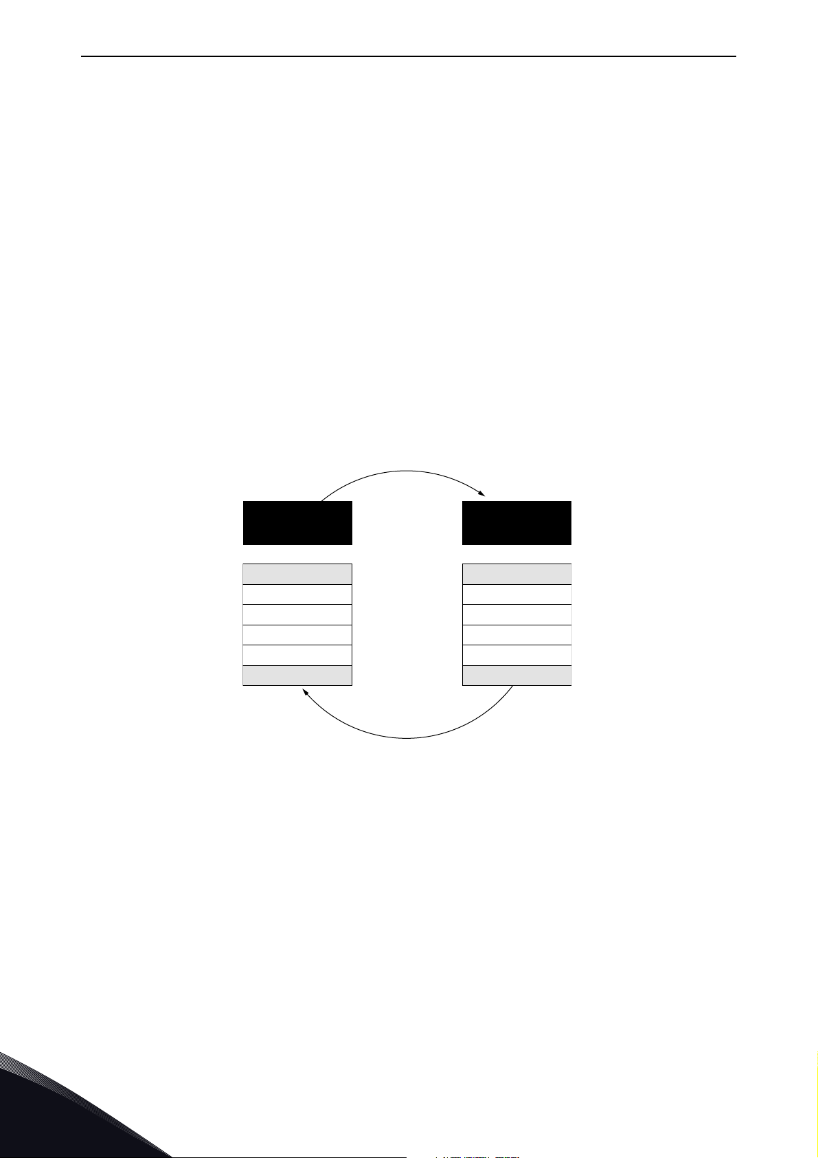
2. MODBUS - GENERAL INFO
Modbus is a communication protocol developed by Modicon systems. In simple terms, it is a way of
sending information between electronic devices. The device requesting the information is called the
Modbus Master (or the Client in Modbus TCP/UDP) and the devices supplying information are Modbus Slaves (in Modbus TCP/UDP servers). The Master can also write information to the Slaves. Modbus is typically used to transmit signals from instrumentation and control devices back to a main
controller or data gathering system.
Standard Modbus network contains one Master device and up to 247 Slave devices. In ModbusRTU
and ModbusUDP networks it is mandatory to define a unique Slave Address (or Unit identifier number) for the every Slave Device. Slave Address is a number between 1 and 247. In ModbusTCP networks, it is not mandatory to define a unique Slave Address, because the IP address identifies the
device.
The Modbus communication interface is built around messages. The format of these Modbus messages is independent of the type of physical interface used. The same protocol can be used regardless of the connection type. Because of this, Modbus gives the possibility to easily upgrade the
hardware structure of an industrial network, without the need for large changes in the software. A
device can also communicate with several Modbus nodes at once, even if they are connected with
different interface types, without the need to use a different protocol for every connection.
2
Figure 1.Basic structure of Modbus frame
On simple interfaces like RS485, the Modbus messages are sent in plain form over the network. In
this case the network is dedicated to Modbus. When using more versatile network systems like
TCP/IP over Ethernet, the Modbus messages are embedded in packets with the format necessary
for the physical interface. In that case Modbus and other types of connections can co-exist at the
same physical interface at the same time. Although the main Modbus message structure is peerto-peer, Modbus is able to function on both point-to-point and multidrop networks.
Each Modbus message has the same structure. Four basic elements are present in each message.
The sequence of these elements is the same for all messages, to make it easy to parse the content
of the Modbus message. A conversation is always started by a master in the Modbus network. A
Modbus master sends a message and—depending of the contents of the message—a slave takes
action and responds to it. There can be more masters in a Modbus network. Addressing in the message header is used to define which device should respond to a message. All other nodes on the
Modbus network ignore the message if the address field does not match their own address.
Local contacts: http://drives.danfoss.com/danfoss-drives/local-contacts/
Page 9

Modbus - general info vacon • 7
Your VACON® 100 family AC drive is equipped with Modbus support as standard. If you need to con-
®
tact VACON
with the Drive Info File taken with VACON
service in problems related to Modbus, send a description of the problem together
®
Live to customer support. If possible, also send a "Wire-
shark" log from the situation if applicable.
Ethernet
Modbus TCP
Switch
Modbus
RTU
master
Modbus RTU
Figure 2.Principal example diagram of Modbus
11781_uk
Local contacts: http://drives.danfoss.com/danfoss-drives/local-contacts/
2
Page 10

vacon • 8 Modbus technical data
3. MODBUS TECHNICAL DATA
3.1 Modbus RTU protocol
Table 2.
Interface RS-485
Data transfer method RS-485 MS/TP, half-duplex
STP (Shielded Twisted Pair), type Belden
9841 or similar
2.5 mm
As described in “Modicon Modbus Protocol Reference Guide”
300, 600, 1200, 2400, 4800, 9600, 19200,
38400, 57600, 76800, 115200 and 230400
bits/s
2
Connections and
communications
Transfer cable
Connector
Electrical isolation Functional
Modbus RTU
Bitrate
Addresses 1 to 247
3.2 Modbus TCP protocol
Table 3.
Interface 100BaseTX, IEEE 802.3 compatible
Data transfer method Ethernet half/full -duplex
Data transfer speed 10/100 MBit/s, autosensing
Connections and
communications
Protocol Modbus TCP
Connector Shielded RJ45 connector
Cable type CAT5e STP
Modbus TCP
Default IP Selectable: Fixed or DHCP (AutoIP)
As described in Modbus Messaging
Implementation Guide
3.3 Modbus UDP vs TCP
In addition to TCP, the VACON® 100 family AC drive supports also UDP starting from following firmware versions:
®
•VACON
•VACON
•VACON
It is recommended that UDP is used when reading and writing rapidly and repetitively (cyclically)
the same data as in case of process data. TCP must be used for single operations, like service data
(e.g. reading or writing parameter values).
100 INDUSTRIAL and VACON® 100 X: FW0072V025
®
100 FLOW: FW0159V016
®
100 HVAC: FW0065V035
3
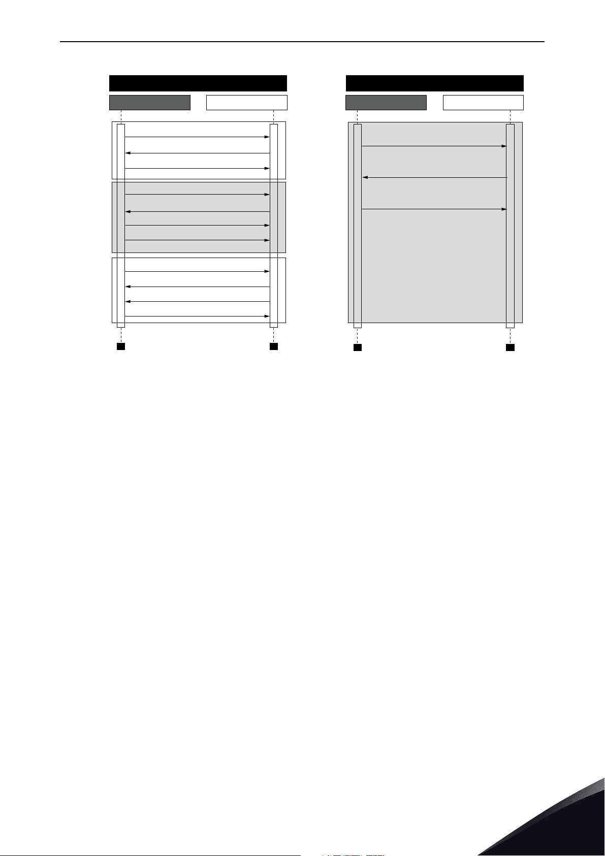
The key difference between UDP and TCP is that when using TCP, each and every Modbus frame
needs to be acknowledged by the receiver (see the figure below). This adds extra traffic to the network and more load to the system (PLC and drives) because software needs to keep track of sent
frames to make sure that they have reached their destination.
Local contacts: http://drives.danfoss.com/danfoss-drives/local-contacts/
Page 11
Modbus technical data vacon • 9
Modbus TCP Communication
PLC
TCP, SYN
TCP, SYN, ACK
Open
Connection
Modbus Response, TCP, ACK
Communicate
Close
Connection
TCP, ACK
Modbus Query
TCP, ACK
Modbus Query
TCP, ACK
TCP, ACK
TCP, FIN, ACK
TCP, ACK
Drive
Modbus UDP Communication
PLC Drive
Modbus Query
Modbus Response
Modbus Query
Communicate
11716_uk
Figure 3. Modbus TCP and UDP communication comparison
Another difference between TCP and UDP is that UDP is connectionless. TCP connections are always opened with TCP SYN messages and closed with TCP FIN or TCP RST. With UDP, the first
packet is already a Modbus query. IP address and port combination is treated as a connection. If
port number changes, it is considered as a new connection or as a second connection if both stay
active.
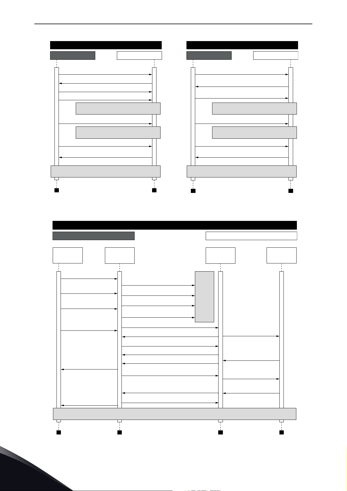
When using UDP, it is not guaranteed that the sent frame reaches its destination. The PLC must
keep track of the Modbus requests by using the Modbus transaction id-field. It actually must do this
also when using TCP. If the PLC does not receive response in time from the AC drive in UDP connection, it needs to send the query again. When using TCP, the TCP/IP stack will keep resending the
request until it has been acknowledged by the receiver (see Figure 4). If the PLC sends new queries
during this time, some of those may not be sent to the network (by TCP/IP stack) until previous sent
package(s) has been acknowledged. This can cause small packet storms when the connection is resumed between the PLC and the AC drive (See Figure 5).
Local contacts: http://drives.danfoss.com/danfoss-drives/local-contacts/
3
Page 12
vacon • 10 Modbus technical data
11717_uk
Modbus TCP Communication
PLC Drive
Modbus Query (1)
Modbus Query (2)
Modbus Response (1), TCP, ACK
Modbus Response (2), TCP, ACK
TCP, ACK
TCP retransmission, Modbus Query (2)
TCP retransmission, Modbus Query (2)
Normal communication continues
Packet lost, no response
Packet lost, no response
Modbus Query (1)
Modbus Response (1)
Modbus Response (4)
Modbus Query (2)
Modbus Query (3)
Modbus Query (4)
Packet lost, no response
Packet lost, no response
Normal communication continues
Modbus UDP Communication
PLC Drive
11718_uk
Modbus TCP Communication
PLC Drive
Modbus Modbus
TCP
stack
TCP
stack
Modbus Query (1)
Modbus Query (2)
Modbus Query (3)
Modbus Query (4)
Modbus Query
(1,2,3)
Modbus Query (4)
Modbus Response
(1,2,3)
Modbus Response
(4)
TCP Modbus Query
TCP, ACK
TCP, ACK
TCP, ACK
TCP, ACK
TCP, Modbus Response (1,2,3)
TCP, Modbus Response (4)
TCP, Modbus Query (4)
Retransmission
Modbus Query (1,2,3)
Retransmission Modbus Query (1,2,3)
Retransmission
Modbus Query (1,2)
Retransmission
Modbus Query (1)
Modbus
Response (1,2,3)
Modbus
Response (4)
Normal communication continues
Packet lost
Figure 4. Modbus TCP and UDP communication errors comparison
Figure 5. Modbus TCP retransmissions
3
Local contacts: http://drives.danfoss.com/danfoss-drives/local-contacts/
Page 13

Modbus technical data vacon • 11
Losing one packet is not a big issue because the same request can be sent again after timeout. In
TCP, the packages always reach their destination but if network congestion causes retransmissions, the resent packages will most likely contain old data or instructions when they reach their
destination.
3.4 Connections and wiring
The VACON® 100 family AC drive supports 10/100Mb speeds in both Full- and Half-duplex modes.
However, real-time process control requires the Full-duplex mode and the 100-megabit speed.
Drives must be connected to the Ethernet network with a Shielded Twisted Pair (STP) CAT-5e cable
(or better). Use only industrial standard components in the network and avoid complex structures
to minimize the length of response time and the amount of incorrect dispatches.
The maximum length of an RS-485 cable depends on the bitrate used, the cable (gauge, capacitance
or characteristic impedance) and the number of devices in the bus. The Modbus RTU specification
states that for a maximum 9600 bits/second bitrate and AWG26 or wider gauge, the maximum
length is 1000 meters. The actual cable length used in an installation can be lower than this number
depending on the aforementioned parameters.
3.5 ACD (Address Conflict Detection) in Ethernet network
The VACON® 100 family AC drive implements the ACD algorithm (IETF RFC 5227).
The ACD algorithm tries to actively detect if the IP address configured to this device is used by another device in the same network. To accomplish this, the ACD sends four ARP request packets
when the device's Ethernet interface goes up or when its IP address changes. The ACD prevents the
use of the Ethernet interface until the ARP probing finishes. This delays the startup of fieldbus protocols about one second. During the delay or after it, the ACD passively checks incoming ARP messages for use of the device's IP address. If another device with the same IP address is detected, the
ACD will try to defend its IP address with a single ARP message. If the other device with the same
IP address also supports ACD, it should stop using the address. If not, the ACD will close the Ethernet connection and indicate the situation with an Alarm. This is done according the "DefendWithPolicyB". Acknowledging of the Alarm is not possible if the problem is active. The ACD opens an
Ethernet connection if the other device with the same IP address disappears from the network. The
alarm can be acknowledged after this. Other policies are not supported. If the fieldbus protocol has
been active, a fieldbus fault may be activated (depends on the fieldbus and drive application configuration).
The ACD functionality can be enabled and disabled with Duplicate IP Detection panel parameter
(see Chapter 5.3.1 Ethernet common settings (M5.9.1)).
Local contacts: http://drives.danfoss.com/danfoss-drives/local-contacts/
3
Page 14
vacon • 12 Installation
M4x55
9174.emf
9000.emf
9235.emf
4. INSTALLATION
4.1 Installation in VACON® 100 family AC drives
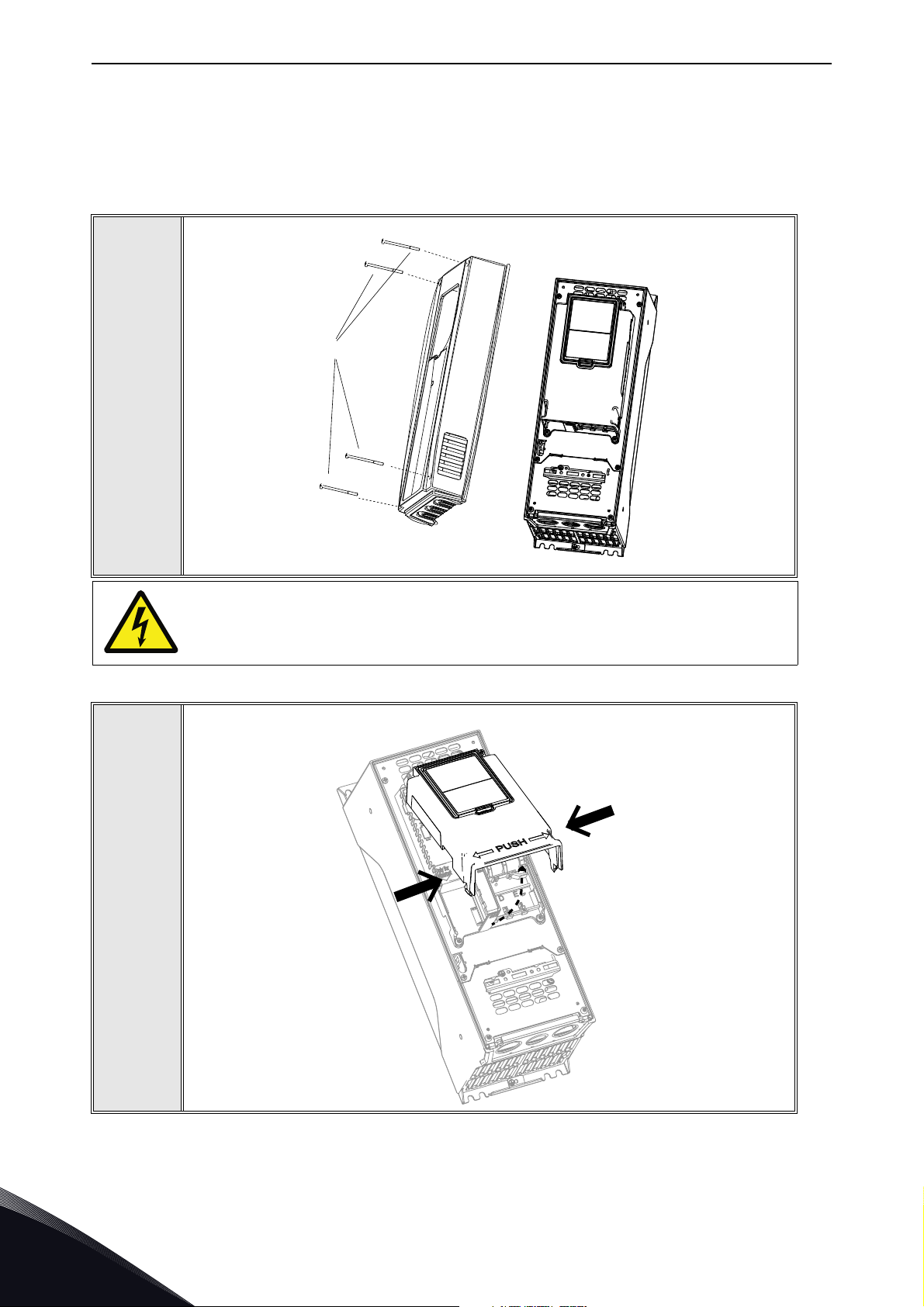
Open the cover of the AC drive.
1
2
The relay outputs and other I/O-terminals may have a dangerous control voltage
present even when the AC drive is disconnected from mains.
Open the inner cover of the drive.
4
Local contacts: http://drives.danfoss.com/danfoss-drives/local-contacts/
Page 15
Installation vacon • 13
Ethernet
cable
9316.emf
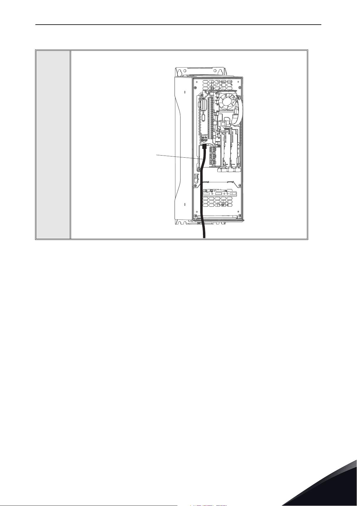
4.1.1 Prepare for use through ethernet
Connect the Ethernet cable (see specification in Chapter 3.2) to its terminal as
shown in figure below.
3
Local contacts: http://drives.danfoss.com/danfoss-drives/local-contacts/
4
Page 16
vacon • 14 Installation
9068.emf
IP54
9265.emf
IP21
Ethernet
cable
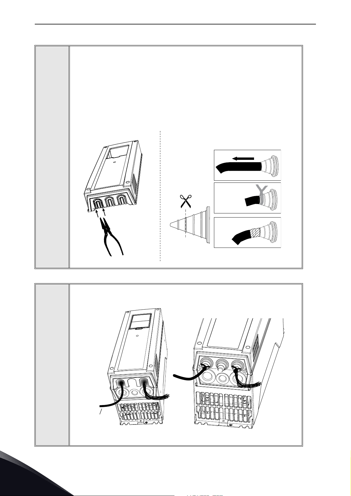
Protection class IP21: Cut free the opening on the AC drive cover for the Ethernet cable.
Protection class IP54: Cut the rubber grommets open to slide the cables
through. Should the grommets fold in while inserting the cable, just draw the
cable back a bit to straighten the grommets up. Do not cut the grommet openings wider than what is necessary for the cables you are using.
NOTE! To meet the requirements of the enclosure class IP54, the connection
between the grommet and the cable must be tight. Therefore, lead the first bit of
the cable out of the grommet straight before letting it bend. If this is not possible, the tightness of the connection must be ensured with insulation tape or a
cable tie.
4
5
Remount the AC drive cover.
NOTE! When planning the cable runs, remember to keep the distance between
the Ethernet cable and the motor cable at a minimum of 30 cm. See figure below.
4
Local contacts: http://drives.danfoss.com/danfoss-drives/local-contacts/
Page 17
Installation vacon • 15
9189.emf
10
5
1
5
m
m
9188.emf
4.1.2 Prepare for use through RS485
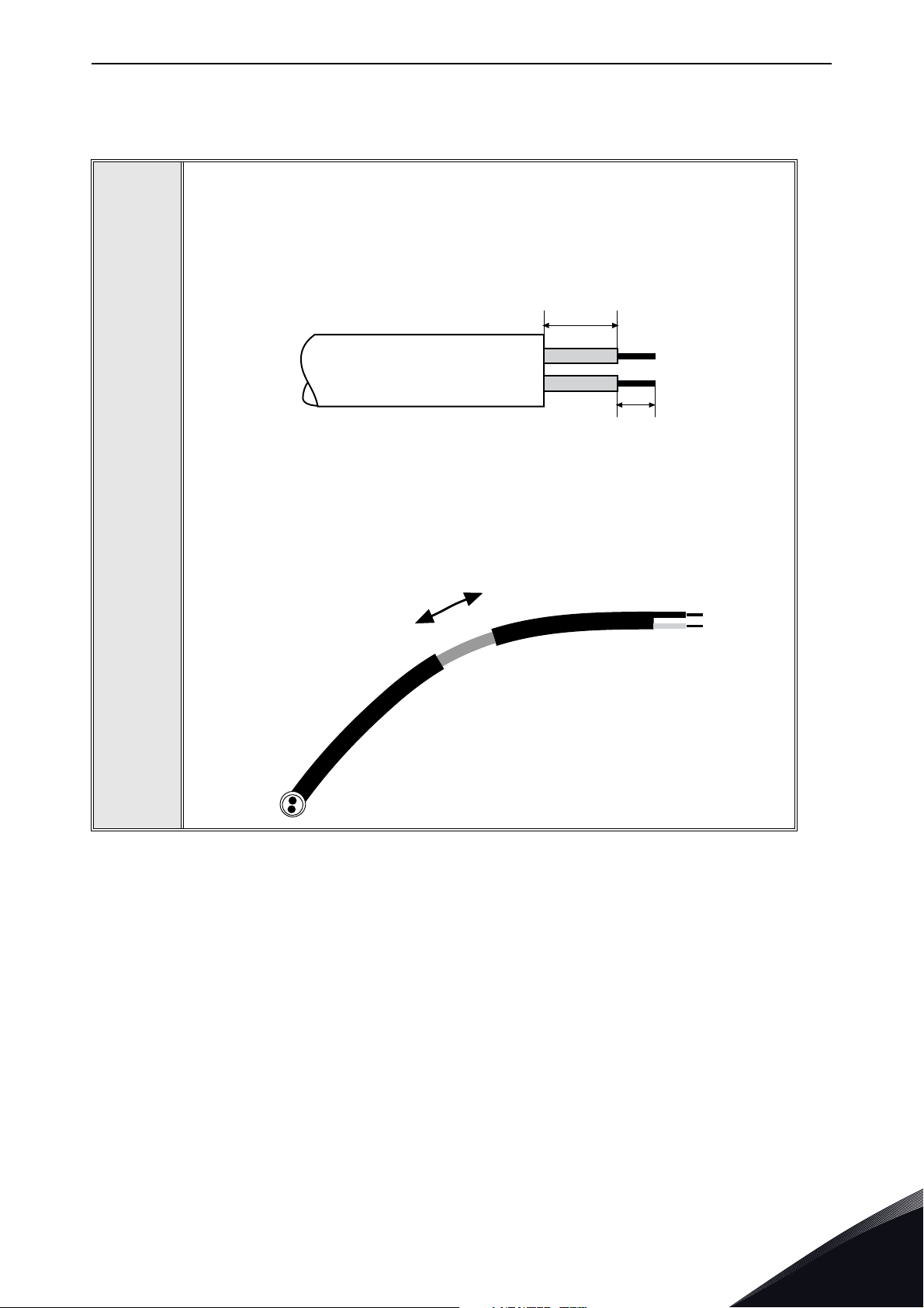
Strip about 15 mm of the RS485 cable (see specification in Chapter 3.1) and cut
off the grey cable shield. Remember to do this for both bus cables (except for the
last device).
Leave no more than 10 mm of the cable outside the terminal block and strip the
cables at about 5 mm to fit in the terminals. See picture below.
Also strip the cable now at such a distance from the terminal that you can fix it to
1
the frame with the grounding clamp. Strip the cable at a maximum length of 15
mm. Do not strip the aluminum cable shield!
Local contacts: http://drives.danfoss.com/danfoss-drives/local-contacts/
4
Page 18

vacon • 16 Installation
Cable clamp
3020.emf
Then connect the cable to its appropriate terminals on VACON® 100 family AC
drive standard terminal block, terminals A and B (A = negative, B = positive). See
figure below.
2
3
Using the cable clamp included in the delivery of the drive, ground the shield of
the RS485 cable to the frame of the AC drive.
NOTE! This can be done in all drives if there is no difference in PE potentialbetween the drives. However, if there is PE potential difference then the shieldshould be connected to PE only at one point in the system. The shields of
thecables shall be joint but not connected to several PE points with different
poten-tial.
NOTE! This is only a principle drawing and the actual drive may look different.
4
Local contacts: http://drives.danfoss.com/danfoss-drives/local-contacts/
Page 19

Installation vacon • 17
RS-485 bus termination
OFF
ON
9110.emf
9201.emf
9202.emf
Fieldbus
cables
If VACON® 100 family AC drive is the last device on the bus, the bus termination
must be set. Locate the DIP switches to the right of the control keypad of the
drive and turn the switch for the RS485 bus termination resistor to position ON.
Biasing is built in the termination resistor. See also step 6 on page 18.
4
5
Unless already done for the other control cables,
cut free the opening on the AC drive cover for the
RS485 cable (protection class IP21).
NOTE! This is only a principle drawing and the
actual drive may look different.
Remount the AC drive cover and run the RS485
cables as shown in picture.
NOTE! When planning the cable runs, remember
to keep the distance between the fieldbus cable
and the motor cable at a minimum of 30 cm.
6
Local contacts: http://drives.danfoss.com/danfoss-drives/local-contacts/
4
Page 20

vacon • 18 Installation
Fieldbus cable
= Bus termination
Termination
activated
Termination
activated with
jumper
Ter min ati on
deactivated
Vacon 100 Vacon 100 Vacon 100 Vacon 100 Vacon 100
3007.emf
The bus termination must be set for the first and the last device of the fieldbus
line. See picture below. See also step 3 on page 17. We recommend that the first
device on the bus and, thus, terminated was the Master device.
7
4
Local contacts: http://drives.danfoss.com/danfoss-drives/local-contacts/
Page 21

Installation vacon • 19
Ethernet
connection
1234567891011
12 13 14 15 16 17 18 19 30
BA
RS485
terminals
4.2 Installation in VACON® 100 X
The AC drive can be connected to fieldbus either through RS485 or Ethernet. The connection for
RS485 is on the standard I/O terminals (A and B) and the connection for Ethernet is left to the control
terminals.
Figure 6.
4.2.1 Prepare for use through Ethernet
1
2
For more detailed information, see the user’s manual of the fieldbus you are using.
Connect the Ethernet cable (see specification in Chapter 3.2) to its terminal and
run the cable through the conduit plate.
Remount the powerhead.
NOTE: When planning the cable runs, remember to keep the distance between
the Ethernet cable and the motor cable at a minimum of 30 cm.
Local contacts: http://drives.danfoss.com/danfoss-drives/local-contacts/
4
Page 22

vacon • 20 Installation
9189.emf
10
5
1
5
m
m
9188.emf
4.2.2 Prepare for use through RS485
Strip about 15 mm of the RS485 cable (see specification in Chapter 3.1) and cut
off the grey cable shield. Remember to do this for both bus cables (except for the
last device).
Leave no more than 10 mm of the cable outside the terminal block and strip the
cables at about 5 mm to fit in the terminals. See picture below.
Also strip the cable now at such a distance from the terminal that you can fix it to
the frame with the grounding clamp. Strip the cable at a maximum length of 15
1
mm. Do not strip the aluminum cable shield!
4
2
3
Then connect the cable to its appropriate terminals on VACON® 100 X AC drive
standard terminal block, terminals A and B (A = negative, B = positive). See
Figure 6.
Using the cable clamp included in the delivery of the drive, ground the shield of
the RS485 cable to the frame of the AC drive.
Local contacts: http://drives.danfoss.com/danfoss-drives/local-contacts/
Page 23

Installation vacon • 21
Modbus RTU
= Bus termination
Term inat ion
activated
Termin atio n
activated
with
DIP switch
Term inat ion
deactivated
Vacon 100 Vacon 100 Vacon 100 Vacon 100 Vacon 100
If VACON® 100 X AC drive is the last device on the bus, the bus termination must
be set. Locate the DIP switches to the top of the control unit (see figure below).
4
5
Turn the right most switch to position “1”. Biasing is built
in the termination resistor. See also step 6.
NOTE: When planning the cable runs, remember to keep
the distance between the fieldbus cable and the motor
cable at a minimum of 30 cm.
The bus termination must be set for the first and the last device of the fieldbus
line. See picture below and step 4. We recommend that the first device on the bus
and, thus, terminated, was the Master device.
Local contacts: http://drives.danfoss.com/danfoss-drives/local-contacts/
4
Page 24

vacon • 22 Fiedlbus parametrization
5. FIEDLBUS PARAMETRIZATION
The following chapter describes briefly how to parametrise the AC drive in order for the motor to be
controllable via fieldbus. These instructions are written for basic applications. For more
information, consult the application-specific manual.
In order for the AC drive to accept commands from the fieldbus network, the control place of the AC
drive has to be set to fieldbus. The default value of the parameter "Control Place" is usually I/O. Note
that if the control unit firmware is updated, the default settings are restored. In addition, some
applications may have the remote speed reference selection set by default to other than fieldbus. In
these cases, the speed reference selection must be set to fieldbus, in order for the speed reference
to be controlled via fieldbus.
NOTE! The motor control mode should be selected to support the used process and profile.
The navigation path to the fieldbus parameters may differ from application to application. The
exemplary paths below apply to the VACON
®
100 family AC drive.
5.1 Fieldbus control and basic reference selection
The following tables list some of the parameters related to fieldbus control in case of VACON®
applications for the VACON
detailed information.
Parameters can be read and written by using the drive panel, PC Tool or fieldbus protocol. See
Chapter 6.3.5 for reading and writing application parameters over Modbus. Notice that some of
connection parameters for fieldbus may need to be set (depending on your configuration) via panel
or PC tool, before you can connect over fieldbus and write application parameters.
Table 4. Parametrization for VACON
Parameter name ID Value Default Panel Tree
Control mode 600
Remote control place 172 1 = Fieldbus CTRL 0 P 3.2.1
Local / remote 211 0 = Remote 0 P 3.2.2
Fieldbus ref. sel. 122 3 = Fieldbus 3 P 3.3.1.10
®
100 family AC drive. See the application specific manuals for more
®
100 family AC drive (Standard application)
0 = Frequency
1 = Speed
2 = Torque
0 P 3.1.2.1
5
5.1.1 Torque control parametrization
Some extra parametrisation has to be made in order to control the frequency control with torque
control. The following instructions are for the VACON
specific manual for more detailed information.
• Motor control mode (ID 600) must be configured to "Torque control" (2).
To configure the drive to use correct torque reference, select the parameter "Torque
Reference Selection" to ProcessDataIn1 (9). This can be done with: PC-tool or panel in panel
tree: P 3.3.2.1, ID 64
Local contacts: http://drives.danfoss.com/danfoss-drives/local-contacts/
®
100 family AC drives, see the application
Page 25

Fiedlbus parametrization vacon • 23
5.1.2 Enabling Modbus protocol
Modbus TCP/UDP is always enabled in VACON
network settings (IP address etc) before using it. See Chapter 5.3.1.
When using Modbus RTU, you need to enable the protocol. After enabling it, protocol settings will
appear under panel tree P5.8.3.
Table 5. Enabling Modbus RTU protocol
Parameter name ID Value Default Panel Tree
0 = No Protocol
RS-485 protocol 2208
1 = Modbus RTU
2 = BACnet MSTP
3 = N2
®
100 family devices. You need to parametrize the
No protocol P 5.8.1.1
5.2 Modbus RTU parameters and monitoring values (M5.8.3)
Table 6. Parameters related with Modbus used through RTU
Panel Tree Parameter Range Default ID Description
P5.8.3.1.1 Slave address 1…247 1 2320
P5.8.3.1.2 Baud rate 300…230400 6 2378
Unique slave device
address.
Communication speed
300
600
1200
2400
4800
9600
19200
38400
57600
76800
115200
230400
1 = 1 stop bit
P5.8.3.1.4 Stopbits 1…3 3 2380
P5.8.3.1.3 Parity type 0…2 0 2379
P5.8.3.1.5
P5.8.3.1.6 * Operate Mode 0…1 0 2374
P5.8.3.1.7.130
* This feature is not supported in VACON® 100 HVAC. The default application in the VACON® 100
family AC drives supports only Slave mode. A special application is required for Master functionality.
Local contacts: http://drives.danfoss.com/danfoss-drives/local-contacts/
Communication
time-out
IDMap IDs 0…65535 0
0…65535 10 2321
3130-
3159
2 = 1.5 stop bits
3 = 2 stop bits
0 = Even
1 = Odd
2 = None
Unit is seconds
0 = Not used
0 = Slave
1 = Master
IDMap IDs
5
Page 26

vacon • 24 Fiedlbus parametrization
5.2.1 Slave address
Each slave must have a unique address (from 1 to 247) so that it can be addressed independently
from other nodes.
5.2.2 Baud rate
Select the communication speed for the network. The default value is 9600 baud.
5.2.3 Parity type
You can select the parity type for the network. Modbus RTU specifies the stop bit configuration
shown in table below. You can modify this stop bit configuration manually using parameter
P5.X.3.1.4.
Table 7. Parity type and stop bits
Parity Stopbits
Even 1
Odd 1
None 2
5.2.4 Stop bits
You can select the stop bit amount for the Modbus RTU network.
5.2.5 Communication timeout
Modbus initiates a communication error for a time defined with this parameter. '0' means that no
fault is generated.
5.2.6 Operate mode
Used to select the operate mode of the Modbus RTU protocol (slave / master). This feature is not
supported in VACON
supports only Slave mode. A special application is required for Master functionality.
®
100 HVAC. The default application in the VACON® 100 family AC drives
Table 8. Operate mode values
Value Description
0Slave
1Master
5
Local contacts: http://drives.danfoss.com/danfoss-drives/local-contacts/
Page 27

Fiedlbus parametrization vacon • 25
5.2.7 IDMap IDs
See Chapter 6.3.8.
Table 9. Monitoring values related with Modbus used through RTU
Panel Tree Parameter Range ID Description
0 = Init
P5.8.3.2.1 Fieldbus protocol status 1…3 2381
P5.8.3.2.2 Communication status 0.0…99.999 2382
P5.8.3.2.3 Illegal functions 0…65535 2383
P5.8.3.2.4 Illegal data addresses 0…65535 2384
P5.8.3.2.5 Illegal data values 0…65535 2385
1 = Stopped
2 = Operational
3 = Faulted
0-99 Number of messages
with errors
0-999 Number of messages
without communication errors
Reset on drive restart
P5.8.3.2.6 Slave device busy 0…65535 2386
P5.8.3.2.7 Memory parity error 0…65535 2387
P5.8.3.2.8 Slave device failure 0…65535 2388
P5.8.3.2.9 Last fault response 0…65535 2389
P5.8.3.2.10 Control word - 2390 Shown as hex value
P5.8.3.2.11 Status word - 2391 Shown as hex value
5.2.8 Fieldbus protocol status
Fieldbus Protocol Status tells the status of the protocol.
Table 10. Fieldbus protocol status descriptions
Status Description
INITIALIZING Protocol is starting up
STOPPED No connections active via fieldbus
OPERATIONAL
FAULTED Fieldbus connection has timedout.
Protocol is running. At least one
active connection
5.2.9 Communication status
The Communication status shows how many good and bad messages the drive has received. The
Communication status includes a common error counter that counts CRC and parity errors and a
counter for good messages.
Local contacts: http://drives.danfoss.com/danfoss-drives/local-contacts/
5
Page 28

vacon • 26 Fiedlbus parametrization
Only messages to the current slave in use are counted in the good messages.
Table 11. Communication status description
Good messages
0…999 Number of messages received without errors
Bad messages
0…99 Number of messages received with errors
5.2.10 Illegal functions
This value counts error situations. The function code received in the query refers to a not allowed
action for the server (or slave). This corresponds to Modbus fault code 01h.
5.2.11 Illegal data addresses
This value counts error situations. The data address received in the query refers to not allowed
address for the server (or slave). This corresponds to Modbus fault code 02h.
5.2.12 Illegal data values
This value counts error situations. A value contained in the query data field refers to a not allowed
value for server (or slave). This corresponds to Modbus fault code 03h.
5.2.13 Slave device busy
This value counts error situations. The server (or slave) is engaged in processing a long-duration
program command. The client (or master) should retransmit the message later when the server (or
slave) is free. This corresponds to Modbus fault code 06h.
5.2.14 Memory parity error
This value counts error situations. The server (or slave) attempted to read record file but detected
a parity error in the memory. This corresponds to Modbus fault code 08h.
5.2.15 Slave device failure
This value counts error situations. An unrecoverable error occurred while the server (or slave) was
attempting to perform the requested action. This corresponds to Modbus fault code 04h.
5.2.16 Last fault response
Shows the last fault response as Fault code.
5
5.2.17 Control word
Shows the Control Word received from the bus.
5.2.18 Status word
Shows the current Status Word that is sent to the bus.
Local contacts: http://drives.danfoss.com/danfoss-drives/local-contacts/
Page 29

Fiedlbus parametrization vacon • 27
5.3 Modbus TCP/UDP parameters and monitoring values
5.3.1 Ethernet common settings (M5.9.1)
Table 12. Ethernet common settings (M5.9.1)
Panel
Tree
P5.9.1.1 IP address mode
P5.9.1.2
P5.9.1.3.1 IP address
P5.9.1.3.2 Subnet mask
P5.9.1.3.3 Default gateway
P5.9.1.4 Active IP address - - 2483
P5.9.1.5
P5.9.1.6
P5.9.1.7 MAC address - - 2486 Drive MAC address
Parameter Range Default ID Description
Duplicate IP
Detection
Active subnet
mask
Active default
gateway
Fixed (1),
DHCP(2)
Disabled (0),
Enabled (1)
1.0.0.0 -
223.255.255.255
0.0.0.0-
255.255.255.255
0.0.0.0-
255.255.255.255
- - 2484
- - 2485
DHCP (2) 2482 IP Mode
This is setting for enabling
ACD (See Chapter 3.4).
enabled 2569
192.168.0.10 2529 Fixed IP address
255.255.0.0 2530 Fixed Subnet mask
192.168.0.1 2531 Fixed default gateway
When disabled drive does
not check for or react to
address conflict situation.
Shows current active IP
address. It is same as fixed
value if IP mode is "Fixed".
Shows current active subnet mask. It is same as fixed
value if IP mode is "Fixed".
Shows current active default
gateway. It is same as fixed
value if IP mode is "Fixed".
5.3.2 IP Address mode
Selectable alternatives are DHCP (Dynamic Host Configuration Protocol) and Fixed. The DHCP
protocol gives IP addresses to new devices connecting to local network. This address is valid for a
certain period of time. If no DHCP server is found, an automatic random IP is given. A fixed IP
address is specified manually and it does not change. When the mode is changed from DHCP to
Fixed the addresses will read:
IP: 192.168.0.10
Subnet mask: 255.255.0.0
Default gateway: 192.168.0.1
5.3.3 Fixed IP address
An IP address is a series of numbers (like above) specific to the device connected to the Internet.
Local contacts: http://drives.danfoss.com/danfoss-drives/local-contacts/
5
Page 30

vacon • 28 Fiedlbus parametrization
5.3.4 Fixed Subnet Mask
The network mask marks all the bits of an IP address for the identification of the network and the
subnetwork.
5.3.5 Fixed default gateway
Gateway address is the IP address of a network point that acts as an entrance to another network.
5.3.6 Active IP address, subnet mask and default gateway
This value cannot be changed. If the IP mode is "fixed", it will display the same value as in Fixed IP
address (5.3.3). If the mode is "DHCP", the value is 0.0.0.0 when the DHCP is retrieving IP settings
or 169.x.x.x if it could not retrieve an address. Otherwise it shows the currently active IP address.
5.3.7 MAC Address
The MAC address of the control board. The MAC address (Media Access Control) is a unique address
given to each network host. It is not editable.
5.3.8 Modbus TCP/UDP settings (M5.9.2)
Table 13. Modbus TCP/UDP parameters
Panel Tree Parameter Range Default ID Description
P5.9.2.1.1 Connection limit 0…3 3 2446 Number of allowed connections
P5.9.2.1.2
P5.9.2.1.3
P5.9.2.1.4.1-30 IDMap IDs 0…65535 0
The monitoring values menu structure is duplicated to all connections. Maximum number of
connections is three (3). Monitoring menus are visible even though connection has not been opened.
Panel Tree Parameter Range Unit Default ID Description
P5.9.2.2.1.1
P5.9.2.2.1.2
Unit identifier
number
Communication
time-out
Table 14. Modbus TCP/UDP Monitoring values
Fieldbus protocol
status
Communication
status
0…255 255 2447 See Chapter 5.2.10
0…65535 10 2448
3100-
3129
1…3 - - 2449
0.0…99.9999 - 0.0 2450
Unit is seconds
0 = Not used
IDMap IDs
1 = Stopped
2 = Operational
3 = Faulted
See 5.2.8
0-99 Number of messages
with errors
0-999 Number of messages
without communication
errors
See 5.2.9
5
P5.9.2.2.1.3 Illegal functions 0…65535 - - 2451 See 5.2.10
P5.9.2.2.1.4
Illegal data
addresses
0…65535 - - 2452 See 5.2.11
Local contacts: http://drives.danfoss.com/danfoss-drives/local-contacts/
Page 31

Fiedlbus parametrization vacon • 29
Table 14. Modbus TCP/UDP Monitoring values
Panel Tree Parameter Range Unit Default ID Description
P5.9.2.2.1.5 Illegal data values 0…65535 - - 2453 See 5.2.12
P5.9.2.2.1.6 Slave device busy 0…65535 - - 2454 See 5.2.13
P5.9.2.2.1.7
P5.9.2.2.1.8
P5.9.2.2.1.9
P5.9.2.2.1.10 Control word - hex - 2458 See 5.2.17
P5.9.2.2.1.11 Status word - hex - 2459 See 5.2.18
5.3.9 Connection limit
Defines how many clients can access the server simultaneously.
Memory parity
error
Slave device failure
Last fault
response
0…65535 - - 2455 See 5.2.14
0…65535 - - 2456 See 5.2.15
0 - - 2457 See 5.2.16
5.3.10 Unit Identifier number
The Modbus 'slave address' field usually used on Modbus Serial Line is replaced by a single byte
'Unit Identifier'.
When the TCP is used as the communications protocol, the AC drive is addressed by its IP address
and broadcast messages are not possible. In this case, the unit identifier is useless. In the UDP, it is
possible to send broadcast messages and therefore the unit identifier becomes important.
To keep things simple, the unit identifier is checked when using both TCP and UDP. In TCP you can
use value 255 (non-significant) as a unit identifier and send the messages to all slaves with that
value.
5.3.11 Communication timeout
For Modbus, this value defines the time in which a message must be received (from Client in
Modbus TCP/UDP) before a fieldbus fault is generated. If timeout is set to zero, no fault is created.
5.3.12 IDMap IDs
See Chapter 6.3.8.
Local contacts: http://drives.danfoss.com/danfoss-drives/local-contacts/
5
Page 32

vacon • 30 Communications
6. COMMUNICATIONS
Features of the Modbus-Vacon interface:
• Direct control of VACON® drive (e.g. Run, Stop, Direction, Speed reference, Fault reset)
®
• Full access to all VACON
®
• Monitor VACON
status (e.g. Output frequency, Output current, Fault code)
6.1 Data addresses in Modbus messages
All data addresses in Modbus messages are referenced to zero. The first occurrence of a data item
is addressed as item number zero. For example:
• The coil known as ‘Coil 1’ in a programmable controller is addressed as ‘Coil 0000’ in the
data address field of a Modbus message.
• Coil 127 decimal is addressed as ‘Coil 007E hex’ (126 decimal).
• Holding register 40001 is addressed as register 0000 in the data address field of the message. The function code field already specifies a ‘holding register’ operation. Therefore the
‘4XXXX’ reference is implicit.
• Holding register 40108 is addressed as register 006B hex (107 decimal).
parameters
6.2 Supported Modbus Functions
The VACON® variables and fault codes as well as the parameters can be read and written from
Modbus. The parameter addresses are determined in the application. Every parameter and actual
value have been given an ID number in the application. The ID numbering of the parameter as well
as the parameter ranges and steps can be found in the application manual in question. The
parameter value must be given without decimals. If several parameters/actual values are read with
one message, the addresses of the parameters/actual values must be consecutive.
Table 15. Supported functions
Func t i o n
(dec)
1 1 Read coils x Discrete (1-bit) 00000-0FFFF
2 2 Read Discrete Inputs x Discrete (1-bit) 10000-1FFFF
3 3 Read Holding Registers x x Register (16bit) 40000-4FFFF
4 4 Read Input Registers x x Register (16bit) 30000-3FFFF
5 5 Write Single Coils x Discrete (1-bit) 00000-0FFFF
6 6 Write Single Register x x Register (16bit) 40000-4FFFF
15 F Write Multiple Coils x Discrete (1-bit) 00000-0FFFF
16 10 Write Multiple Registers x x Register (16bit) 40000-4FFFF
Function
(hex)
Modbus Function Name
TCP/
UDP
RTU Access type
Address
range (hex)
6
23 17 Read/Write Multiple Registers x x Register (16bit) 40000-4FFFF
NOTE! Broadcasting not supported in TCP.
Broadcast supported with function code 06 and 16 in RTU and in UDP.
The address ranges of the different function codes are in many cases not relevant to the user and
can be ignored. The targeted information type (coil, register etc.) can be selected separate from the
address.
Local contacts: http://drives.danfoss.com/danfoss-drives/local-contacts/
Page 33

Communications vacon • 31
6.3 Modbus data mapping
6.3.1 Coils registers
A "coil" in Modbus is a single-bit binary data item which can be both read and written. In VACON
100 family AC drives, the coils refer to some bits in the fieldbus control word." See page 34.
Table 16. Defined coil registers
Address Function Purpose
0001 RUN/STOP Control Word, bit 0
0002 Direction Control Word, bit 1
0003 Fault reset Control Word, bit 2
0017 Reset Clears operation days trip counter
0018 Reset Clears energy trip counter
6.3.2 Clearing resettable counters
The VACON
reset to zero by writing value '1' to addresses defined in table below. You can also use coils defined
in chapter 6.3.1.
®
AC drives have trip counters for operation days and energy. These counters can be
Table 17. Clearing trip counters
Address Function Purpose
®
40101 Reset Clears operation days trip counter
40301 Reset Clears energy trip counter
6.3.3 Discrete inputs
A "discrete input" in Modbus is a single-bit binary data item which is read-only. In VACON
family AC drives, the discrete inputs refer to the fieldbus status word bits. See Chapter 10.
Table 18. Defined Input Discrete
Address Function Purpose
10001 Ready Status Word, bit 0
10002 Run Status Word, bit 1
10003 Direction Status Word, bit 2
10004 Fault Status Word, bit 3
10005 Alarm Status Word, bit 4
10006 At reference Status Word, bit 5
10007 Zero speed Status Word, bit 6
10008 Flux ready Status Word, bit 7
®
100
Local contacts: http://drives.danfoss.com/danfoss-drives/local-contacts/
6
Page 34

vacon • 32 Communications
6.3.4 Holding registers and input registers
An "input register" in Modbus is a 16-bit value which is read-only. A "holding register" in Modbus is
a 16-bit value which can be both read and written. Holding and input registers are accessed using
different function codes, and the address ranges are different. In VACON
same information can be accessed as input registers and holding registers, i.e. input register X
refers to the same 16-bit value as the holding register X.
The Modbus registers are mapped to the VACON
Table 19. Defined holding registers
®
100 family AC drive as follows:
®
100 family AC drives, the
Address range Purpose
0001 - 2000 Vacon Application IDs 16bit Table 20 RW 30/30
2001 - 2019 FBProcessDataIN 16bit Table 21 RW 19/19
2051 - 2086 FBProcessDataIN 32bit Table 21 RW 36/36
2101 - 2119 FBProcessDataOUT 16bit Table 22 RO 19/0
2151 - 2186 FBProcessDataOUT 32bit Table 22 RO 36/0
2200 - 10000 Vacon Application IDs 16bit Table 20 RW 30/30
10501 - 10530 IDMap 16bit Figure 7. RW 30/30
10601 - 10630 IDMap Read/Write 16bit Table 23 RW 30/30
10701 - 10760 IDMap Read/Write 32bit Table 24 RW 30/30
20001 - 40000 Vacon Application IDs 32bit Table 20 RW 30/30
40001 - 40005 Operation day counter 16bit Table 26 RO 5/0
40011 - 40012 Operation day counter 32bit Table 25 RO 2/0
40101 - 40105
40111 - 40112
40201 - 40203 Energy counter 16bit Table 30 RO 3/0
40211 - 40212 Energy counter 32bit Table 29 RO 2/0
Resettable operation
day counter
Resettable operation
day counter
Access
type
16bit Table 28
32bit Table 27 RO 2/0
See R/W
R, Write 1 to
first index
to reset
Max R/W
size
5/0
6
40301 - 40303
40311 - 40312
40401 - 40430 Fault history 16bit Table 33 RO 30/0
40501
40511-40568
Accessing unsupported values returns the error code "Illegal Data Address".
Resettable energy counter
Resettable energy counter
Communication time
out
Fault history with 16 bit
fault codes
Local contacts: http://drives.danfoss.com/danfoss-drives/local-contacts/
16bit Table 32
32bit Table 31 RO 2/0
16bit Table 35 RW 1/1
16bit Table 34 RO 30/0
R, Write 1 to
first index
to reset
3/0
Page 35

Communications vacon • 33
6.3.5 Vacon Application IDs
Application IDs are parameters that depend on the drive's application. These parameters can be
read and written by pointing the corresponding memory range directly or by using the so-called ID
map (more information below). The easiest way to read a single parameter value or parameters with
consecutive ID numbers is to use a straight address. It is possible to read 30 consecutive ID
addresses. Notice that the operation will fail if even one of the consecutive IDs do not exist for such
case see Chapter 6.3.8 ID map.
Parameters which have 32 bit value can be read from their own range. For example, if you want to
read the value for ID 864 (FB Status Word), the address must be set to 21726. This address value
comes from values: 20000 + ((ID -1) * 2). The ID value is reduced with one because of zero-based
addressing and the result is multiplied with 2 because one 32 bit value will take two (16 bit)
addresses.
Table 20. Application IDs
Address range Purpose Application ID
0001-2000 16 bit application parameters 1-2000
2200-10000 16 bit application parameters 2200-10000
20001-40000 32 bit application parameters 1-10000
6.3.6 FB Process data IN
The process data fields are used to control the drive (e.g. Run, Stop , Reference, Fault Reset) and to
quickly read actual values (e.g. Output frequency, Output current, Fault code). The fields are
structured as follows:
Local contacts: http://drives.danfoss.com/danfoss-drives/local-contacts/
6
Page 36

vacon • 34 Communications
Process Data Master -> Slave (max 22 bytes)
Table 21. Fieldbus Process Data IN
Address
Name Range/Type
16-bit
*
32-bit
2001
2002 - FB General Control Word Binary coded
2003
2004
2005
2006
2007
2008
2009
2010
2011
2051 = High data
2052 = Low data
2053 = High data
2054 = Low data
2055 = High data
2056 = Low data
2057 = High data
2058 = Low data
2059 = High data
2060 = Low data
2061 = High data
2062 = Low data
2063 = High data
2064 = Low data
2065 = High data
2066 = Low data
2067 = High data
2068 = Low data
2069 = High data
2070 = Low data
FB Control Word Binary coded
FB Speed Reference 0…10000 (100%)
FB Process Data In 1
FB Process Data In 2
FB Process Data In 3
FB Process Data In 4
FB Process Data In 5
FB Process Data In 6
FB Process Data In 7
FB Process Data In 8
See Chapter 9.
APPENDIX 1 PROCESS DATA
*. In VACON® 100 family AC drives, the Control Word and the Status Word are
formed of 32 bits. Only the initial 16 bits can be read in the 16-bit area.
Control word bits
For control word bit descriptions, see Chapter 10. APPENDIX 2 - CONTROL AND STATUS WORD.
6.3.7 FB Process data OUT
Process Data Slave -> Master (max 22 bytes)
Table 22. Fieldbus Process Data Out
Address
Name Range/Type
16-bit 32-bit
2101
2102 -
2103
2151 = High data
2152 = Low data
2153 = High data
2154 = Low data
FB Status Word Binary coded
In case of 16-bit, FB General
Status Word (High data)
FB Actual Speed
Binary coded
0…10000
(100.00%)
6
Local contacts: http://drives.danfoss.com/danfoss-drives/local-contacts/
Page 37

Communications vacon • 35
Table 22. Fieldbus Process Data Out
Address
Name Range/Type
16-bit 32-bit
2104
2105
2106
2107
2108
2109
2110
2111
Status Word bits
For status word bit descriptions, see Chapter 10. APPENDIX 2 - CONTROL AND STATUS WORD.
2155 = High data
2156 = Low data
2157 = High data
2158 = Low data
2159 = High data
2160 = Low data
2161 = High data
2162 = Low data
2163 = High data
2164 = Low data
2165 = High data
2166 = Low data
2167 = High data
2168 = Low data
2169 = High data
2170 = Low data
FB Process Data Out 1
FB Process Data Out 2
FB Process Data Out 3
FB Process Data Out 4
FB Process Data Out 5
FB Process Data Out 6
FB Process Data Out 7
FB Process Data Out 8
See Chapter 9.
APPENDIX 1 PROCESS DATA
6.3.8 ID map
Using the ID map, you can read consecutive memory blocks that contain parameters whose ID's are
not in a consecutive order. The address range 10501 - 10530 is called 'IDMap', and it includes an
address map in which you can write your parameter ID's in any order. The address range 10601 to
10630 is called 'IDMap Read/Write,' and it includes values for parameters written in the IDMap. As
soon as one ID number has been written in the map cell 10501, the corresponding parameter value
can be read and written in the address 10601, and so on. The address range 10701 - 10760 contains
the ID Map read/write for 32bit values. Maximum of 30 IDs and ID values can be written and read
with single request.
IDMap IDs can be also configured from the panel or VACON
under Modbus TCP and Modbus RTU settings. See details in chapters 5.1 and 5.2.2.
®
Live PC tool. IDmap menu is located
Local contacts: http://drives.danfoss.com/danfoss-drives/local-contacts/
6
Page 38

vacon • 36 Communications
ID Value
699 123
700 321
701 456
702 654
703 1789
704 987
705 2741
706 1147
707 258
708 3852
Parameters
Address Data: ID
10501 700
10502 702
10503 707
10504 704
Address Data: ID
10601 321
10602 654
10603 258
10604 987
ID Map
11609_uk
Figure 7. IDMap initialization
Once the IDMap address range has been initialized with any parameter ID number, the parameter
value can be read and written in the IDMap Read/Write address range address IDMap address + 100.
If the IDMap table has not been initialized, all data fields are showing the value '0'. Once the IDMap
table has been initialized, the parameter ID's are stored in the VACON
memory.
Example of 32Bit IDMap
Table 24. Example of parameter values in 32-bit IDMap Read/Write registers
6.3.9 Operation day counter
Control unit operating time counter (total value). This counter cannot be reset. The values are read
only.
6
Table 23. Parameter Values in 16-bit IDMap Read/Write registers
Address Data
10601 Data included in parameter ID700
10602 Data included in parameter ID702
10603 Data included in parameter ID707
10604 Data included in parameter ID704
®
100 family AC drive’s flash
Address Data
10701 Data High, parameter ID700
10702 Data Low, parameter ID700
10703 Data High, parameter ID702
10704 Data Low, parameter ID702
Local contacts: http://drives.danfoss.com/danfoss-drives/local-contacts/
Page 39

Communications vacon • 37
Operation day counter as seconds
This counter in registers 40011d to 40012d holds the value of operation days as seconds in a 32-bit
unsigned integer.
Table 25. Operation days counter as seconds
Address Description
40011 High data
40012 Low data
Operation day counter
This counter in registers 40001d to 40005d holds the value of operation days counter. The values are
read only.
Table 26. Operation day counter
Holding register address Input register address Purpose
40001 1 Years
40002 2 Days
40003 3 Hours
40004 4 Minutes
40005 5 Seconds
6.3.10 Resettable operation day counter
This register holds the value for resettable control unit operating time counter (trip value). The
values are read only.
For resetting this counter see Chapter 6.3.2.
Holds the counter value as seconds.
Resettable operation day counter as seconds
This counter in registers 40111d to 40112d holds the value of resettable operation days as seconds
in a 32-bit unsigned integer.
Table 27. Resettable operation days counter as seconds
Address Description
40111 High data
40112 Low data
Resettable operation day counter
This counter in registers 40101d to 40105d holds the value of operation days counter.
Table 28. Resettable operation day counter
Holding register
address
40101 101 Years
40102 102 Days
40103 103 Hours
40104 104 Minutes
Input register
Holds the counter value as seconds.
address
Purpose
40105 105 Seconds
Local contacts: http://drives.danfoss.com/danfoss-drives/local-contacts/
6
Page 40

vacon • 38 Communications
6.3.11 Energy counter
This counter holds the value of total amount of energy taken from a supply network. This counter
cannot be reset. The values are read only.
Energy counter as kWh
This counter is in registers 40211d to 40212d and is a 32-bit floating point (IEEE 754) value
containing the number of kilowatt-hours (kWh) that is in the drive's energy counter. This value is
read-only.
Table 29. Energy counter as kWh
Address Description
40211 High data
40212 Low data
Energy counter
These registers hold three values for the energy counter, amount of energy used, format of the
energy value and unit of the energy value.
Example: If energy = 1200, format = 52, unit = 1, then actual energy is 12.00 kWh.
Table 30. Energy count e r
Holding register
address
40201 201 Energy
40202 202 Format
40203 203
Input register
address
Holds the value of energy counter in
kWh. Datatype is 32 bit float IEEE 754
Purpose Description
Amount of energy taken from a supply
network.
The last number of the Format field indicates the decimal point place in the
Energy field.
Example:
40 = 4 number of digits, 0 fractional digits
41 = 4 number of digits, 1 fractional digit
42 = 4 number of digits, 2 fractional digits
Unit
1 = kWh
2 = MWh
3 = GWh
4 = TWh
Unit of the value.
6
Local contacts: http://drives.danfoss.com/danfoss-drives/local-contacts/
Page 41

Communications vacon • 39
6.3.12 Resettable energy counter
This counter holds the value of total amount of energy taken from a supply network since the
counter was last reset. For resetting this counter see Chapter 6.3.2". The values are read only.
Resettable energy counter as kWh
This counter is in registers 40311d to 40312d and is a 32-bit floating point (IEEE 754) value
containing the number of kilowatt-hours (kWh) that is in the drive's resettable energy counter.
Table 31. Resettable energy counter as kWh
Address Description
40311 High data
40312 Low data
Resettable energy counter
These registers hold three values for the energy counter, amount of energy used, format of the
energy value and unit of the energy value.
Example: If energy = 1200, format = 52, unit = 1, then actual energy is 12.00 kWh
Table 32. Resettable energy counter
Holding
register
address
40301 301 Energy
40302 302 Format
Input
register
address
Purpose Description
Holds the value of energy counter in
kWh since last counter reset.
Datatype is 32 bit float IEEE 754
Amount of energy taken from a supply
network.
The last number of the Format field indicates the decimal point place in the
Energy field.
Example:
40 = 4 number of digits, 0 fractional digits
41 = 4 number of digits, 1 fractional digit
42 = 4 number of digits, 2 fractional digits
Unit
1 = kWh
40303 303
Local contacts: http://drives.danfoss.com/danfoss-drives/local-contacts/
2 = MWh
3 = GWh
4 = TWh
Unit of the value.
6
Page 42

vacon • 40 Communications
6.3.13 Fault history
The fault history can be viewed by reading from address 40401 onward. The faults are listed in
chronological order so that the latest fault is mentioned first and the oldest last. The fault history
can contain 29 faults at the same time. The fault history contents are represented as follows.
NOTE! Reading the fault history items is slow. Reading all 30 items at once might take up to 600
milliseconds.
Table 33. Fault history
Holding register
address
40401 401
40402 402
40403 403
... ...
40429 429
6.3.14 Fault history with 16-bit error codes
The fault history can be viewed by reading from address 40511 onward. The faults are listed in a
chronological order so that the latest fault is mentioned first and the oldest last. These addresses
contain the fault code and the subcode for the fault. Reading can be started from any address.
Table 34. Fault history with 16-bit error codes
Holding register
address
40511 Fault code 1 16-bit fault code in index 1.
Input register
address
Upper byte is a fault code, lower byte
Purpose Description
Purpose
is a sub code
40512 Sub code 1 16-bit sub code for the fault in index 1.
40513 Fault code 2 16-bit fault code in index 2.
40514 Sub code 2 16-bit sub code for the fault in index 2.
... ...
40567 Fault code 29
40568 Sub code 29
6
Local contacts: http://drives.danfoss.com/danfoss-drives/local-contacts/
Page 43

Communications vacon • 41
6.4 Modbus TCP/UDP communication and connection timeout
It is possible to open up to three Modbus TCP/UDP connections to the VACON® 100 family AC drive.
One of the connections could be used for process data and other just for reading monitoring data.
In most cases it is desirable that if "monitor" connection gets disconnected, no fault is generated
but when the connection is handling the process data, a fault should be generated in the time
specified.
This register address enables the user to give custom communication timeout for each connection.
If a custom timeout value is used, it must be given every time a connection is opened. Timeout can
be set only to the connection which is been used to access this register. By default the connection
uses the communication timeout value given via panel parameters.
If the cable is disconnected, a fieldbus fault is activated after the timeout period. When
communication timeout is zero, no fault is activated.
In Modbus RTU you can only have one connection, so there is no need to use this value.
Table 35. Communication timeout register
Holding
register
address
Purpose Description
40501
Communication timeout zero?
Connection closed or broken?
Broken
Has second connection with
communication timeout
other than zero?
Communication
timeout
Timeout
No
No
Connection timeout value for this
connection in seconds.
Communicating
No
Received packet during
communication
timout time?
Yes
Closed
Yes
CheckYes
FAULT! No fault
Figure 8. The Modbus TCP/UDP function in case of timeout
Local contacts: http://drives.danfoss.com/danfoss-drives/local-contacts/
7092_uk
6
Page 44

vacon • 42 Communications
6.5 Example messages
6.5.1 Example 1 - Write Process Data
Write the process data 42001…42003 with command 16 (Preset Multiple Registers).
Command Master - Slave:
Table 36.
ADDRESS 01 hex Slave address 1 hex (= 1)
FUNCTION 10 hex Function 10 hex (= 16)
Starting address HI 07 hex
Starting address LO D0 hex
No. of registers HI 00 hex
No. of registers LO 03 hex
Byte count 06 hex Byte count 06 hex (= 6)
DATA
ERROR
CHECK
Message frame:
01 10 07 D0 00 03 06 00 01 00 00 13 88 C8 CB
Data HI 00 hex
Data LO 01 hex
Data HI 00 hex
Data LO 00 hex
Data HI 13 hex
Data LO 88 hex
CRC HI C8 hex
CRC LO CB hex
Table 37.
Starting address 07D0 hex (= 2000)
Number of registers 0003 hex (= 3)
Data 1 = 0001 hex (= 1). Setting control word run bit to 1.
Data 2 = 0000 hex (= 0).
Data 3 = 1388 hex (= 5000), Speed Reference to 50.00%
CRC field C8CB hex (= 51403)
6
The reply to Preset Multiple Registers message is the echo of 6 first bytes.
Answer Slave - Master:
Table 38.
ADDRESS 01 hex Slave address 1 hex (= 1)
FUNCTION 10 hex Function 10 hex (= 16)
DATA
ERROR
CHECK
Starting address HI 07 hex
Starting address LO D0 hex
No. of registers HI 00 hex
No. of registers LO 03 hex
CRC HI 80 hex
CRC LO 85 hex
Local contacts: http://drives.danfoss.com/danfoss-drives/local-contacts/
Starting address 07D0 hex (= 2000)
Number of registers 0003 hex (= 3)
CRC 8085 hex (= 32901)
Page 45

Communications vacon • 43
Reply frame:
Table 39.
01 10 07 D0 00 03 80 85
6.5.2 Example 2 - Read process data
Read the Process Data 42103…42104 with command 4 (Read Input Registers).
Command Master - Slave:
Table 40.
ADDRESS 01 hex Slave address 1 hex (= 1)
FUNCTION 04 hex Function 4 hex (= 4)
DATA
ERROR
CHECK
Starting address HI 08 hex
Starting address LO 36 hex
No. of registers HI 00 hex
No. of registers LO 02 hex
CRC HI 93 hex
CRC LO A5 hex
Starting address 0836 hex (= 2102)
Number of registers 0002 hex (= 2)
CRC field 93A5 hex (= 37797)
Message frame:
Table 41.
01 04 08 36 00 02 93 A5
The reply to the Read Input Registers message contains the values of the read registers.
Answer Slave - Master:
Table 42.
ADDRESS 01 hex Slave address 1 hex (= 1)
FUNCTION 04 hex Function 4 hex (= 4)
Byte count 04 hex Byte count 4 hex (= 4)
DATA
ERROR
CHECK
Data HI 13 hex
Data LO 88 hex
Data HI 09 hex
Data LO C4 hex
CRC HI 78 hex
CRC LO E9 hex
Speed reference = 1388 hex (=5000 => 50.00%)
Output Frequency = 09C4 hex (=2500 =>25.00Hz)
CRC field 78E9 hex (=30953)
Local contacts: http://drives.danfoss.com/danfoss-drives/local-contacts/
6
Page 46

vacon • 44 Communications
Reply frame:
Table 43.
01 04 04 13 88 09 C4 78 E9
6.5.3 Example 3 - Exception response
In an exception response, the Slave sets the
The Slave returns an exception code in the data field.
Command Master - Slave:
ADDRESS 01 hex Slave address 1 hex (= 1)
FUNCTION 04 hex Function 4 hex (= 4)
Starting address HI 17 hex
DATA
ERROR
CHECK
Message frame:
01 04 17 70 00 05 34 66
Starting address LO 70 hex
No. of registers HI 00 hex
No. of registers LO 05 hex
CRC HI 34 hex
CRC LO 66 hex
Table 45.
most-significant bit (MSB) of the function code to 1.
Table 44.
Starting address 1770 hex (= 6000)
Invalid number of registers 0005 hex (= 5)
CRC field 3466 hex (=13414)
Exception response:
Answer Slave - Master:
ADDRESS 01 hex Slave address 1 hex (= 1)
FUNCTION 84 hex Most significant bit set to 1
DATA
ERROR
CHECK
Reply frame:
Table 47.
01 84 04 42 C3
Error
code
CRC HI 42 hex
CRC LO C3 hex
04 hex Error code 04 => Slave Device Failure
Table 46.
CRC field 42C3 hex (= 17091)
6
Local contacts: http://drives.danfoss.com/danfoss-drives/local-contacts/
Page 47

Fault tracing vacon • 45
7. FAULT TRACING
When an unusual operating condition is detected by the AC drive control diagnostics, the drive initiates a notification visible, for example, on the keypad. The keypad will show the ordinal number of
the fault, the fault code and a short fault description.
The fault can be reset with the Reset button on the control keypad or via the I/O terminal. The faults
are stored in the Fault history menu which can be browsed. The different fault codes you will find
in the table below. This fault table presents only the faults related to the fieldbus in use.
NOTE! When contacting distributor or factory because of a fault condition, always write down all
texts and codes on the keypad display and send a description of the problem together with the
Info File
to your local support.
7.1 Typical fault conditions
Table 48. Typical fault conditions
Fault condition Possible cause Remedy
Drive
Termination
resistor
Cabling
Grounding Inadequate grounding.
Connections
Parameter
Missing or excessive termination resistor.
• Supply or motor cables are located
too close to the fieldbus cable
• Wrong type of fieldbus cable
• Too long cabling
Faulty connections.
• Excessive stripping of cables
• Conductors in wrong terminals
• Too loose connections of conductors
• Faulty address
• Overlapping slave addresses
• Wrong baud rate
• Wrong control place selected
Install termination resistors at both ends of the
fieldbus line.
Ensure grounding in all
points on the net
7.2 RS-485 bus biasing
When none of the devices on the RS-485 bus is sending data, all devices are in idle status. This being
the case, the bus voltage is in indefinate state, usually near 0 V due to the termination resistors. This
may cause problems in character reception because the single characters in serial communication
begin with start bit referring to bus status '0' with voltage of less than -200mV whereas the bus status '1' corresponds to bus voltage of more than +200mV. The RS-485 standard considers the voltage
interval -200mV...+200mV as undefined state. Bus biasing is therefore needed to maintain the voltage in status ‘1’ (above +200mV) also between the messages.
To bias the bus you will have to add a separate active termination resistor specifically designed for
the RS-485 bus (e.g. Siemens active RS 485 terminating element (6ES7972-0DA00-0AA0)).
Local contacts: http://drives.danfoss.com/danfoss-drives/local-contacts/
7
Page 48

vacon • 46 Fault tracing
.
Check cabling
Check grounding
9330.emf
No communication
Counter OK
Poor
communication
Check communi-
cation status (par.
5.7.3.2.1/5.8.3.2.2)
Counter does not
run
Counter for bad
frames (see Table
3) increases
Check fieldbus
parameters
bus parameters in
menu
Check other field-
Check selected
protocol
Check termination
resistors
Check that both
ends of the fieldbus
line hav termi-
nation resistors
(chapter 4.4)
Check parameters
e
Is the device in
READY state?
Check Master’s
parameters
Is fieldbus selected
as control place?
Does Master give
RUN command?
Check cabling
Check termination
resistors
Other bus devices
Check connections
Check the led on
keypad
Check external
interlockings (I/O)
Check configura-
tions (Sla e add-
ress, baudrate etc.)
v
Check distances
between cables,
see chapter 4.4.
Check cable types,
see chapter 3.
Check grounding,
see chapter 4. Re-
member to make
grounding for each
device!
Check terminalsfor
loose connections
Check stripping of
cables and
conductors, see
chapter 4.
Use keypad to
monitor variable
Check that both
ends of th fieldbus
line have t rmina-
tion resistors
(chapter 4.4)
e
e
Check cable for
cuts
Check correctplace-
ment of conductors
in terminals
Check other
necessary devices
(e.g. router)
Drive does not
start from the bus
Check parameter
M1.15 or M3.2.1
7.3 Other fault conditions
The following fault tracing diagram will help you to locate and fix some of the most usual problems.
If the problem persists contact your local distributor.
Figure 9. Fault tracing diagram for Modbus RTU
Local contacts: http://drives.danfoss.com/danfoss-drives/local-contacts/
7
Page 49

Fault tracing vacon • 47
.
Check cabling
Check parameter
M1.15 OR P3.2.1
No communication
Counter OK
Poor
communication
Check communi-
cation status (par.
5.7.3.2.1/5.8.3.2.2)
Counter does not
run
Counter for bad
frames (see Table
3) increases
Check fieldbus
parameters
busparametersin
menu
Check other field-
Check selected
protocol
Is the device in
READY state?
Check Master’s
parameters
Is fieldbus selected
as control place?
Does Master give
RUN command?
Check cabling
Other bus devices
Check connections
Check the led on
keypad
Check external
interlockings (I/O)
Check distances
between cables,
see chapter 4.4.
Check stripping of
cables and
conductors, see
chapter 4.
Use keypad to
monitor variable
Check cable for
cuts
Check correct place-
ment of conductors
in terminals
Check other
necessary devices
(e.g. router)
Drive does not
start from the bus
Check cable types
and lenghts, see
chapter 3.
Check e.g WLAN
or other routers
Check IP address,
gateway etc.
9329.emf
7
Local contacts: http://drives.danfoss.com/danfoss-drives/local-contacts/
Figure 10. Fault tracing diagram for Modbus TCP
Page 50

vacon • 48 Quick setup
8. QUICK SETUP
Following these instructions, you can easily and fast set up your Modbus for use:
Choose control place.
1
2
A. Press LOC/REM button on keypad to select
Select Fieldbus as remote control place: Main Menu > Quick Setup (M1) >
B.
Rem. Ctrl. Place (P1.15) > FieldbusCTRL
Make these settings in the master software
A. Set Control Word to '0' by writing the data 0000h to the register 2001
B. Set Control Word to '1' by writing the data 0001h to the register 2001
C. AC drive status is RUN
D. Set Speed Reference value to '5000' (=50.00%) by writing the data 1388h to the
register 2003
E.
Actual speed is 5000 (25.00 Hz if MinFreq is 0.00 Hz and MaxFreq is 50.00 Hz)
F. Set Control Word to '0' by writing the data 0000h to the register 2001
G. AC drive status is STOP.
.
d
Remote Control Place
.
d
.
d
.
d
8
Local contacts: http://drives.danfoss.com/danfoss-drives/local-contacts/
Page 51

APPENDIX 1 - PROCESS DATA vacon • 49
9. APPENDIX 1 - PROCESS DATA
Process Data IN (Master to Slave)
Use of Process Data In variables depends on the used application. The configuration of the data is
free.
Process Data OUT (Slave to Master)
Use of Process Data Out variables depends on the used application.
The Fieldbus Master can read the AC drive’s actual values using process data variables. Control
applications use process data as follows:
Table 49. Process Data OUT variables
Table 50.
Register Data Default ID Information Unit
2104 Process data OUT 1
2105 Process data OUT 2
2106 Process data OUT 3
2107 Process data OUT 4
2108 Process data OUT 5
2109 Process data OUT 6
2110 Process data OUT 7
2111 Process data OUT 8
NOTE 1! In VACON
®
VACON
100 HVAC the Motor Current scale is always 0.1 A.
NOTE 2! In VACON
®
100 family AC drives, the Motor Current scale depends on the drive size. In
®
100 HVAC, the default ID is 45 meaning "Motor Current 1 Decimal". In VACON®
1
2
3(45)
4
5
6
7
37
Output Frequency 0.01 Hz
Motor Speed 1 rpm
2
Motor Current 0.1 A
Motor Torque 0.1 %
Motor Power 0.1 %
Motor Voltage 0.1 V
DC link voltage 1 V
Active Fault Code -
100 family AC drives, the default ID is 3 for Motor Current. The ID 45 can be mapped by the user to
®
this variable also in VACON
100 family AC drives.
Local contacts: http://drives.danfoss.com/danfoss-drives/local-contacts/
9
Page 52

vacon • 50 APPENDIX 2 - CONTROL AND STATUS WORD
10. APPENDIX 2 - CONTROL AND STATUS WORD
10.1 Control Word bit description
The Control word is composed of 32 bits. FBFixedControlWord consist of the first 16 bits. FBGeneralControlWord consist of the remaining 16 bits. While the functionality of FBFixedControlWord is
fixed in the VACON
application specific and can vary even in the VACON
The meanings of FBFixedControlWord bits are described below. Unused bits have to be set to zero.
NOTE! This table is valid for VACON
functions. See Table 52.
Bit Function Value Description
®
standard applications, the functionality of FBGeneralControlWord is totally
®
standard applications. VACON® 100 HVAC may not support all
Table 51. Control Word
®
standard applications.
0 Start/Stop
1 Direction
2Fault reset
3Stop mode 1
4Stop mode 2
5 Quick ramp time
6 Freeze Setpoint
7Setpoint to Zero
8
Request Fieldbus
Control
0 Stop request from fieldbus.
1 Run request from fieldbus.
0 Requested direction is "FORWARD".
1 Requested direction is "REVERSE".
0 No action.
1
0 Stop mode is unmodified.
1 Stop mode is overridden to "Coasting".
0 Stop mode is unmodified.
1 Stop mode is overridden to "Ramping".
0 Normal deceleration ramp time.
1
0
1
0
1 The setpoint value from fieldbus is changed to 0.
0
1 Control Place is overridden to Fieldbus Control.
Rising edge (0->1) = Active faults, alarms and
infos are reset.
Deceleration ramp time is switched to shorter
than normal.
Changes in the setpoint value from fieldbus (FB
Speed Reference) are taken into use by the application.
Changes in the setpoint value from fieldbus (FB
Speed Reference) are not taken into use by the
application.
The setpoint value from fieldbus is taken from FB
Speed Reference.
Control Place is as parameterized in the drive
(unchanged).
10
9
10 Jogging 1
Request Fieldbus
Reference
Source of the setpoint value is as parameterized
0
in the drive (unchanged).
Source of the setpoint value is overridden to
1
Fieldbus.
0 No action.
1 Jogging request with reference 1.
Local contacts: http://drives.danfoss.com/danfoss-drives/local-contacts/
Page 53

APPENDIX 2 - CONTROL AND STATUS WORD vacon • 51
Table 51. Control Word
Bit Function Value Description
11 Jogging 2
12 Quick stop
13 - 15 Reserved
Table 52. Control word bit support in VACON
Bit Function
0Start/Stop x x
1 Direction x x
2Fault reset x x
3 Stop mode 1 x x
4 Stop mode 2 x x
5 Quick ramp time x
6 Freeze setpoint x x
7Setpoint to Zero x
8 Request Fieldbus Control x x
0 No action.
1 Jogging request with reference 2.
0 No action
1 Drive executes quick stop / emergency stop.
®
100 family AC drives
VACON® 100
INDUSTRIAL / FLOW
VACON® 100 HVAC
9 Request Fieldbus Reference x x
10 Jogging 1 x
11 Jogging 2 x
12 Quick stop x
13-15 Reserved
Local contacts: http://drives.danfoss.com/danfoss-drives/local-contacts/
10
Page 54

vacon • 52 APPENDIX 2 - CONTROL AND STATUS WORD
10.2 Status Word Descriptions
The Status word is composed of 32 bits. FBFixedStatusWord consist of the first 16 bits. FBGeneralStatusWord consist of the remaining 16 bits. While the functionality of FBFixedStatusWord is
fixed in the VACON
application specific and can vary even in the VACON
The meanings of FBFixedStatusWord bits are described below. Unused bits have to be set to zero.
®
standard applications, the functionality of FBGeneralStatusWord is totally
Table 53. Status Word
Bit Function Description
®
standard applications.
B0 Ready
B1 Run
B2 Direction
B3 Fault
B4 Alarm
B5 At reference
B6 Zero speed
B7 Flux ready
B8-B12 Reserved
0Drive is not ready.
1 Drive is ready to run.
0 Motor is not running.
1 Motor is running.
0 Motor is running clockwise.
1 Motor is running counterclockwise.
0No fault active.
1 Drive has an active fault.
0 No alarm active.
1 Drive has active alarm.
0 Motor is not running at reference speed.
1 Motor is running at reference speed.
0 Motor is not at zero speed.
1 Motor is running at zero speed.
0 Motor is not magnetized.
1 Motor is magnetized.
10
The following table is valid for most of VACON 100 applications.
Table 54. Status Word bits B29-B31, descriptions of bit connections
B29
Control place
00 1 Fieldbus
01 0 Keypad
0 1 1 PC tool
10 0 I/O terminals
B30
Control place
Local contacts: http://drives.danfoss.com/danfoss-drives/local-contacts/
B31
Control place
Description
Page 55

APPENDIX 6 - LWIP LICENCE vacon • 53
11. APPENDIX 6 - LWIP LICENCE
License for LWIP
Copyright (c) 2001, 2002 Swedish Institute of Computer Science.
All rights reserved.
Redistribution and use in source and binary forms, with or without modification, are permitted
provided that the following conditions are met:
1.Redistributions of source code must retain the above copyright notice, this list of conditions and
the following disclaimer.
2.Redistributions in binary form must reproduce the above copyright notice, this list of conditions
and the following disclaimer in the documentation and/or other materials provided with the distribution.
3.The name of the author may not be used to endorse or promote products derived from this software without specific prior written permission.
THIS SOFTWARE IS PROVIDED BY THE AUTHOR “AS IS” AND ANY EXPRESS OR IMPLIED
WARRANTIES, INCLUDING, BUT NOT LIMITED TO, THE IMPLIED WARRANTIES OF
MERCHANTABILITY AND FITNESS FOR A PARTICULAR PURPOSE ARE DISCLAIMED. IN NO EVENT
SHALL THE AUTHOR BE LIABLE FOR ANY DIRECT, INDIRECT, INCIDENTAL, SPECIAL, EXEMPLARY,
OR CONSEQUENTIAL DAMAGES (INCLUDING, BUT NOT LIMITED TO, PROCUREMENT OF
SUBSTITUTE GOODS OR SERVICES; LOSS OF USE, DATA, OR PROFITS; OR BUSINESS
INTERRUPTION) HOWEVER CAUSED AND ON ANY THEORY OF LIABILITY, WHETHER IN CONTRACT,
STRICT LIABILITY, OR TORT (INCLUDING NEGLIGENCE OR OTHERWISE) ARISING IN ANY WAY OUT
OF THE USE OF THIS SOFTWARE, EVEN IF ADVISED OF THE POSSIBILITY OF SUCH DAMAGE.
Local contacts: http://drives.danfoss.com/danfoss-drives/local-contacts/
11
Page 56

www.danfoss.com
Vacon Ltd
Member of the Danfoss Group
Runsorintie 7
65380 Vaasa
Finland
Document ID:
DPD00156D
Rev. D
Sales code: DOC-INSMODBUS+DLUK
 Loading...