

Operating Guide
VACON® 100 Wall-mounted Drives
VACON® 100 INDUSTRIAL, VACON® 100 FLOW,
VACON® 100 HVAC


Operating Guide | VACON® 100 Wall-mounted Drives
Contents
Contents
1 Introduction 7
1.1 Additional Resources 7
1.2 Disposal 7
1.3 Type Approvals and Certifications 7
2 Safety 9
2.1 Safety Symbols 9
2.2 Danger and Warnings 9
2.3 Cautions and Notices 11
3 Product Overview 13
3.1 Manual Version 13
3.2 Package Label 13
3.3 Description of the Type Code 14
3.4 Enclosure Sizes 15
4 Receiving the Delivery 19
4.1 Checking the Delivery 19
4.2 Accessories 19
4.2.1 Accessories Bag, MR4 19
4.2.2 Accessories Bag, MR5 19
4.2.3 Accessories Bag, MR6 20
4.2.4 Accessories Bag, MR7 20
4.2.5 Accessories Bag, MR8 21
4.2.6 Accessories Bag, MR9 21
4.3 Storing the Product 22
4.4 Lifting the Enclosure Sizes MR8 and MR9 22
4.5 Using the Product Modified Label 23
5 Mounting 25
5.1 Wall-mounting Requirements 25
5.2 Flange-mounting Requirements 25
5.3 Cooling Requirements 27
5.3.1 General Cooling Requirements 27
5.3.2 Cooling 27
5.3.3 Necessary Quantity of Cooling Air 30
6 Electrical Installation 31
6.1 Cable Connections 31
6.1.1 General Cable Requirements 31
AQ298036140958en-000101 / | 3Danfoss A/S © 2019.05

Operating Guide | VACON® 100 Wall-mounted Drives
6.1.2 UL Standards on Cabling 32
6.1.3 Cable Selection and Dimensioning 32
6.1.4 Cable Selection and Dimensioning, North America 32
6.1.5 Fuse Selection 33
6.1.6 Fuse Selection, North America 33
6.1.7 Brake Resistor Cables 33
6.2 EMC-compliant Installation 34
6.2.1 Installation in a Corner-grounded Network 35
6.3 Grounding 35
6.4 Get Access and Locate the Terminals 36
6.4.1 Get Access and Locate the Terminals for MR4-MR7 36
6.4.2 Get Access and Locate the Terminals for MR8 38
6.4.3 Get Access and Locate the Terminals for MR9 40
6.5 Installation of Cables 43
6.5.1 Additional Instructions for Cable Installation 43
6.5.2 Installing the Cables, MR4-MR7 44
6.5.3 Installing the Cables, MR8-MR9 48
6.6 Installation in an IT System 53
6.6.1 Installing the AC drive in an IT System, MR4-MR6 53
6.6.2 Installing the AC drive in an IT System, MR7 55
6.6.3 Installing the AC drive in an IT System, MR8 58
6.6.4 Installing the AC drive in an IT System, MR9 60
6.7 Installation in a Marine Environment 63
Contents
7 Control Unit 64
7.1 Control Unit Components 64
7.2 Control Unit Cabling 65
7.2.1 Selection of the Control Cables 65
7.2.2 Control Unit Terminals 65
7.3 DIP Switches on the Control Unit 67
7.3.1 Selection of Terminal Functions with DIP Switches 67
7.3.2 Isolation of the Digital Inputs from Ground 69
7.4 Fieldbus Connection 69
7.4.1 Fieldbus Terminals 69
7.4.2 Internal Fieldbuses in VACON® 100 Products 70
7.4.3 General Cabling Instructions for Fieldbus 71
7.4.3.1 Cable Routing 71
7.4.3.2 Strain Relief 73
7.4.4 Ethernet Commissioning and Cabling 73
7.4.4.1 General Cabling Instructions for Ethernet 73
7.4.4.2 Grounding the Cable Shield 73
7.4.4.3 Using Fieldbus through an Ethernet Cable 75
AQ298036140958en-000101 /4 | Danfoss A/S © 2019.05

Operating Guide | VACON® 100 Wall-mounted Drives
7.4.5 RS485 Commissioning and Cabling 78
7.4.5.1 General Cabling Instructions for RS485 78
7.4.5.2 Grounding the Cable Shield 79
7.4.5.3 The RS485 Bus Biasing 80
7.4.5.4 Using Fieldbus through an RS485 Cable 80
7.5 Available Option Boards 84
7.6 Option Board Installation 85
7.7 Battery for the Real-Time Clock (RTC) 87
7.8 Galvanic Isolation Barriers 87
7.9 Description of the Control Panel 88
7.9.1 Control Panel and the Keypad 88
7.9.2 Displays of the Control Panel 89
Contents
8 Commissioning 91
8.1 Safety Checks before Starting the Commissioning 91
8.2 Commissioning the AC Drive 92
8.3 Measuring the Cable and Motor Insulation 92
8.3.1 Insulation Checks of the Motor Cable 93
8.3.2 Insulation Checks of the Mains Cable 93
8.3.3 Insulation Checks of the Motor 93
8.4 Checking the AC Drive after Commissioning 94
9 Maintenance 95
9.1 Maintenance Schedule 95
10 Specifications 96
10.1 Weight of the Drive 96
10.2 Dimensions 96
10.2.1 Dimensions for Wall-mounting 96
10.2.1.1 Dimensions for Wall-mounting for MR4 96
10.2.1.2 Dimensions for Wall-mounting for MR5 97
10.2.1.3 Dimensions for Wall-mounting for MR6 98
10.2.1.4 Dimensions for Wall-mounting for MR7 99
10.2.1.5 Dimensions for Wall-mounting for MR8 100
10.2.1.6 Dimensions for Wall-mounting for MR9 101
10.2.2 Dimensions for Flange-mounting 102
10.2.2.1 Dimensions for Flange-mounting for MR4 102
10.2.2.2 Dimensions for Flange-mounting for MR5 103
10.2.2.3 Dimensions for Flange-mounting for MR6 104
10.2.2.4 Dimensions for Flange-mounting for MR7 105
10.3 Cable and Fuse Sizes 105
10.3.1 List of Cable and Fuse Size Information 105
10.3.2 Cable and Fuse Sizes, Mains Voltage 208–240 V and 380–500 V 106
AQ298036140958en-000101 / | 5Danfoss A/S © 2019.05

Operating Guide | VACON® 100 Wall-mounted Drives
10.3.3 Cable and Fuse Sizes, Mains Voltage 525–690 V 107
10.3.4 Cable and Fuse Sizes, Mains Voltage 208–240 V and 380–500 V, North America 109
10.3.5 Cable and Fuse Sizes, Mains Voltage 525–690 V, North America 111
10.4 Cable Stripping Lengths 112
10.5 Tightening Torques of the Terminals 113
10.6 Power Ratings 114
10.6.1 Power Ratings of VACON® 100 INDUSTRIAL, 208–240 V 114
10.6.2 Power Ratings of VACON® 100 INDUSTRIAL, 380–500 V 116
10.6.3 Power Ratings of VACON® 100 INDUSTRIAL, 525–600 V 117
10.6.4 Power Ratings of VACON® 100 INDUSTRIAL, 525–690 V 118
10.6.5 Power Ratings of VACON® 100 FLOW, 208–240 V 119
10.6.6 Power Ratings of VACON® 100 FLOW, 380–500 V 120
10.6.7 Power Ratings of VACON® 100 FLOW, 525–600 V 121
10.6.8 Power Ratings of VACON® 100 FLOW, 525–690 V 122
10.6.9 Power Ratings of VACON® 100 HVAC, 208–240 V 123
10.6.10 Power Ratings of VACON® 100 HVAC, 380–500 V 124
10.7 Overload Capability 124
10.8 Brake Resistor Ratings 126
10.8.1 Brake Resistor Ratings 126
10.8.2 Brake Resistance in Light duty and Heavy Duty 126
10.8.3 Brake Resistor Types, Mains Voltage 208–240 V and 380–500 V 127
10.8.4 Brake Resistor Types, Mains Voltage 525–690 V 127
10.8.5 Brake Resistance and Brake Power, Mains Voltage 208–240 V 128
10.8.6 Brake Resistance and Brake Power, Mains Voltage 380–500 V 129
10.8.7 Brake Resistance and Brake Power, Mains Voltage 525–600 V 129
10.8.8 Brake Resistance and Brake Power, Mains Voltage 525–690 V 129
10.9 Control Connections 130
10.10 Technical Data, VACON® 100 INDUSTRIAL 133
10.11 Technical Data, VACON® 100 FLOW 138
10.12 Technical Data, VACON® 100 HVAC 142
Contents
AQ298036140958en-000101 /6 | Danfoss A/S © 2019.05

Operating Guide | VACON® 100 Wall-mounted Drives
Introduction
1 Introduction
1.1 Additional Resources
Other resources are available to understand advanced AC drive functions and operation.
• VACON® 100 INDUSTRIAL Application Guide
• VACON® 100 FLOW Application Guide
• VACON® 100 HVAC Application Guide
• VACON® 100 Enclosed Drives Installation Manual
• VACON® 100 IP00 Drive Modules Installation Manual
• VACON® 100 X Installation Manual
• Instructions for operation with option boards and other optional equipment.
Supplementary publications and manuals are available from Danfoss.
For US and Canada market:
NOTE! Download the English and French product manuals with applicable safety, warning and caution information from https://
www.danfoss.com/en/service-and-support/.
REMARQUE Vous pouvez télécharger les versions anglaise et française des manuels produit contenant l'ensemble des informations
de sécurité, avertissements et mises en garde applicables sur le site https://www.danfoss.com/en/service-and-support/.
1.2 Disposal
Context:
Do not dispose of equipment containing electrical components together with domestic waste. Collect it separately in accordance with
local and currently valid legislation.
1.3 Type Approvals and Certifications
The following list is a selection of possible type approvals and certifications for Danfoss drives:
Danfoss A/S © 2019.05
AQ298036140958en-000101 / DPD01711| 7
089
Operating Guide | VACON® 100 Wall-mounted Drives
Introduction
NOTI CE
The specific approvals and certification for the drive are on the nameplate of the drive. For more information, contact the local
Danfoss office or partner.
8 | Danfoss A/S © 2019.05
AQ298036140958en-000101 / DPD01711
Operating Guide | VACON® 100 Wall-mounted Drives
2 Safety
2.1 Safety Symbols
The following symbols are used in this manual:
DA NG ER
Indicates a hazardous situation which, if not avoided, will result in death or serious injury.
WA RN IN G
Indicates a hazardous situation which, if not avoided, could result in death or serious injury.
CA UT IO N
Indicates a hazardous situation which, if not avoided, could result in minor or moderate injury.
Safety
NO TI CE
Indicates information considered important, but not hazard-related (for example, messages relating to property damage).
2.2 Danger and Warnings
DA NG ER
SHOCK HAZARD FROM POWER UNIT COMPONENTS
The power unit components are live when the drive is connected to mains. A contact with this voltage can lead to death or
serious injury.
Do not touch the components of the power unit when the drive is connected to mains. Before connecting the drive to
-
mains, make sure that the covers of the drive are closed.
DA NG ER
SHOCK HAZARD FROM TERMINALS
The motor terminals U, V, W, the brake resistor terminals, or the DC terminals are live when the drive is connected to mains, also
when the motor does not operate. A contact with this voltage can lead to death or serious injury.
Do not touch the motor terminals U, V, W, the brake resistor terminals, or the DC terminals when the drive is connected to
-
mains. Before connecting the drive to mains, make sure that the covers of the drive are closed.
Danfoss A/S © 2019.05
AQ298036140958en-000101 / DPD01711| 9
Operating Guide | VACON® 100 Wall-mounted Drives
DA NG ER
SHOCK HAZARD FROM DC LINK OR EXTERNAL SOURCE
The terminal connections and the components of the drive can be live 5 minutes after the drive is disconnected from the mains
and the motor has stopped. Also the load side of the drive can generate voltage. A contact with this voltage can lead to death
or serious injury.
Before doing electrical work on the drive:
-
• Disconnect the drive from the mains and make sure that the motor has stopped.
• Lock out and tag out the power source to the drive.
• Make sure that no external source generates unintended voltage during work.
• Wait 5 minutes before opening the cabinet door or the cover of the AC drive.
• Use a measuring device to make sure that there is no voltage.
WA RN IN G
SHOCK HAZARD FROM CONTROL TERMINALS
The control terminals can have a dangerous voltage also when the drive is disconnected from mains. A contact with this
voltage can lead to injury.
Make sure that there is no voltage in the control terminals before touching the control terminals.
-
Safety
WA RN IN G
ACCIDENTAL MOTOR START
When there is a power-up, a power break, or a fault reset, the motor starts immediately if the start signal is active, unless the
pulse control for Start/Stop logic is selected. If the parameters, the applications or the software change, the I/O functions
(including the start inputs) can change. If you activate the auto reset function, the motor starts automatically after an automatic
fault reset. See the Application Guide. Failure to ensure that the motor, system, and any attached equipment are ready for start
can result in personal injury or equipment damage.
Disconnect the motor from the drive if an accidental start can be dangerous. Make sure that the equipment is safe to
-
operate under any condition.
WA RN IN G
LEAKAGE CURRENT HAZARD
Leakage currents exceed 3.5 mA. Failure to ground the drive properly can result in death or serious injury.
Ensure the correct grounding of the equipment by a certified electrical installer.
-
WA RN IN G
SHOCK HAZARD FROM PE CONDUCTOR
The drive can cause a DC current in the PE conductor. Failure to use a residual current-operated protective (RCD) device Type B
or a residual current-operated monitoring (RCM) device can lead to the RCD not providing the intended protection and
therefore can result in death or serious injury.
Use a type B RCD or RCM device on the mains side of the drive.
-
10 | Danfoss A/S © 2019.05
AQ298036140958en-000101 / DPD01711
Operating Guide | VACON® 100 Wall-mounted Drives
2.3 Cautions and Notices
CA UT IO N
DAMAGE TO THE AC DRIVE FROM INCORRECT MEASUREMENTS
Doing measurements on the AC drive when it is connected to mains can damage the drive.
Do not do measurements when the AC drive is connected to mains.
-
CA UT IO N
DAMAGE TO THE AC DRIVE FROM INCORRECT SPARE PARTS
Using spare parts that are not from the manufacturer can damage the drive.
Do not use spare parts that are not from the manufacturer.
-
CA UT IO N
DAMAGE TO THE AC DRIVE FROM INSUFFICIENT GROUNDING
Not using a grounding conductor can damage the drive.
Make sure that the AC drive is always grounded with a grounding conductor that is connected to the grounding terminal
-
that is identified with the PE symbol.
Safety
CA UT IO N
CUT HAZARD FROM SHARP EDGES
There can be sharp edges in the AC drive that can cause cuts.
Wear protective gloves when mounting, cabling, or doing maintenance operations.
-
CA UT IO N
BURN HAZARD FROM HOT SURFACES
Touching surfaces, which are marked with the 'hot surface' sticker, can result in injury.
Do not touch surfaces which are marked with the 'hot surface' sticker.
-
NO TI CE
DAMAGE TO THE AC DRIVE FROM STATIC VOLTAGE
Some of the electronic components inside the AC drive are sensitive to ESD. Static voltage can damage the components.
Remember to use ESD protection always when working with electronic components of the AC drive. Do not touch the
-
components on the circuit boards without proper ESD protection.
Danfoss A/S © 2019.05
AQ298036140958en-000101 / DPD01711| 11

Operating Guide | VACON® 100 Wall-mounted Drives
NO TI CE
DAMAGE TO THE AC DRIVE FROM MOVEMENT
Movement after installation can damage the drive.
Do not move the AC drive during operation. Use a fixed installation to prevent damage to the drive.
-
NO TI CE
DAMAGE TO THE AC DRIVE FROM INCORRECT EMC LEVEL
The EMC level requirements for the AC drive depend on the installation environment. An incorrect EMC level can damage the
drive.
Before connecting the AC drive to the mains, make sure that the EMC level of the AC drive is correct for the mains.
-
NO TI CE
RADIO INTERFERENCE
In a residential environment, this product can cause radio interference.
Take supplementary mitigation measures.
-
Safety
NO TI CE
MAINS DISCONNECTION DEVICE
If the AC drive is used as a part of a machine, the machine manufacturer must supply a mains disconnection device (refer to EN
60204-1).
NO TI CE
MALFUNCTION OF FAULT CURRENT PROTECTIVE SWITCHES
Because there are high capacitive currents in the AC drive, it is possible that the fault current protective switches do not
operate correctly.
NO TI CE
VOLTAGE WITHSTAND TESTS
Doing voltage withstand tests can damage the drive.
Do not do voltage withstand tests on the AC drive. The manufacturer has already done the tests.
-
12 | Danfoss A/S © 2019.05
AQ298036140958en-000101 / DPD01711

Operating Guide | VACON® 100 Wall-mounted Drives
3 Product Overview
3.1 Manual Version
This manual is regularly reviewed and updated. All suggestions for improvement are welcome.
The original language of this manual is English.
Table 1: Manual and Software Version
Edition Remarks
DPD01711H Information about the new enclosure size MR9B and internal fieldbuses was added.
Information about option boards was updated.
EC declaration was removed.
Information about VACON® 100 IP00 drive modules was removed.
Hyperlink to company web page was updated.
Product Overview
Structure of the manual was changed.
Minor changes throughout the manual.
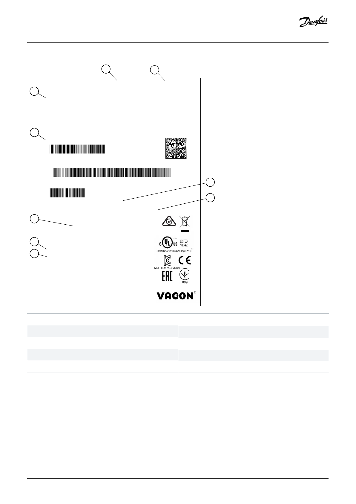
3.2 Package Label
The package label gives detailed information about the delivery.
Danfoss A/S © 2019.05
AQ298036140958en-000101 / DPD01711| 13
1003350719
V00002373919
70-AB3L00045W04B220BM2H-00055783
135U1814
Danfoss A/S, 6430 Nordborg, Denmark
1.5kW:400V / 2HP:480V
IP21/Type1
3~AC,0-Uin, 0-320Hz,
Uin:3~AC,380-500V, 50/60Hz,4.6A
Made in Finland
POWER:
4.8A
OUTPUT:
INPUT:
Danfoss S.A.
DLES
VACON0100-3L-0004-5-FLOW+FL03+DPAP+
190304
0021396473
FW0159V021
Marks:
Cust. Ord. No:
Application:
Firmware:
B.ID:
V00002373919
S/N:
70-AB3L00045W04B220BM2H-00055783
Code:
Type:
AC DRIVE
A
C
B
D
F
E
G
H
I
e30bh338.10
Operating Guide | VACON® 100 Wall-mounted Drives
Product Overview
A The batch ID
C The type code
E The mains voltage
G The protection rating
B
The VACON® order number
D The serial number
F The nominal output current
H The application code
I The order number of the customer
Illustration 1: Package Label of VACON® 100 Wall-mounted Drives
3.3 Description of the Type Code
The type code of VACON® is made of standard codes and optional codes. Each part of the type code agrees to the data in the order.
14 | Danfoss A/S © 2019.05
AQ298036140958en-000101 / DPD01711

Operating Guide | VACON® 100 Wall-mounted Drives
Example:
The code can have this format, for example:
• VACON0100-3L-0061-5+IP54
• VACON0100-3L-0061-5-FLOW
Table 2: Description of the Type Code
Code Description
Product Overview
VACON0100
3L Input/Function: 3L = A 3-phase input
0061 The drive rating in amperes. For example, 0061 = 61 A
5 The mains voltage:
FLOW The product:
+IP54 The optional codes. There are many options, for example +IP54 (an AC drive with the protection rating IP54).
The product family: VACON0100 = the VACON® 100 product family
2 = 208–240 V
5 = 380–500 V
6 = 525–600 V
7 = 525–690 V
(empty) = The VACON® 100 INDUSTRIAL AC drive
FLOW = The VACON® 100 FLOW AC drive
HVAC = The VACON® 100 HVAC AC drive
3.4 Enclosure Sizes
The codes for nominal current and nominal mains voltage are part of the type code (see 3.3 Description of the Type Code) on the
package label (see 3.2 Package Label). Use these values to find out the enclosure size of the AC drive from the table.
In the example "VACON0100-3L-0061-5+IP54", the code for nominal current is 0003 and the code for nominal mains voltage is 5.
Danfoss A/S © 2019.05
AQ298036140958en-000101 / DPD01711| 15
Operating Guide | VACON® 100 Wall-mounted Drives
Table 3: Enclosure Sizes
Nominal mains voltage Nominal current Enclosure size
2 (208–240 V) 0003 MR4
0004
0007
0008
0011
0012
0018 MR5
0024
0031
0048 MR6
0062
0075 MR7
Product Overview
0088
0105
0140 MR8
0170
0205
0261 MR9A
0310
16 | Danfoss A/S © 2019.05
AQ298036140958en-000101 / DPD01711

Operating Guide | VACON® 100 Wall-mounted Drives
Nominal mains voltage Nominal current Enclosure size
5 (380–500 V) 0003 MR4
0004
0005
0008
0009
0012
0016 MR5
0023
0031
0038 MR6
0046
0061
0072 MR7
Product Overview
0087
0105
0140 MR8
0170
0205
0261 MR9A
0310
0386 MR9B
Danfoss A/S © 2019.05
AQ298036140958en-000101 / DPD01711| 17

Operating Guide | VACON® 100 Wall-mounted Drives
Nominal mains voltage Nominal current Enclosure size
6 (525–600 V) 0004 MR5
0006
0009
0011
0018 MR6
0022
0027
0034
0041 MR7
0052
0062
0080 MR8
0100
Product Overview
0125
0144 MR9A
0208
0262 MR9B
7 (525–690 V) 0007 MR6
0010
0013
0018
0022
0027
0034
0041 MR7
0052
0062
0080 MR8
0100
0125
18 | Danfoss A/S © 2019.05
0144 MR9A
0170
0208
0262 MR9B
AQ298036140958en-000101 / DPD01711
Operating Guide | VACON® 100 Wall-mounted Drives
Receiving the Delivery
4 Receiving the Delivery
4.1 Checking the Delivery
Context:
Procedure
1. After you remove the packaging, examine the drive for transport damages.
A If the drive was damaged during the shipping, speak to the cargo insurance company or the carrier.
2. To make sure that the delivery is correct, compare your order data to the data on the package label.
A If the delivery does not agree with your order, speak to the vendor immediately.
3. To make sure that the contents of the delivery is correct and complete, compare the type designation of the product to the type
code.
4.2 Accessories
4.2.1 Accessories Bag, MR4
Table 4: The Content of the Accessories Bag
Item Quantity Description
M4x16 screw 11 Screws for the grounding clamps for cable shield (6), the grounding
clamps for control cable (3), and the grounding clamps for grounding
conductor (2)
M4x8 screw 1 Screw for the optional grounding
M5x12 screw 1 Screw for the external grounding of the drive
Grounding clamp for control cable 3 Control cable grounding
Grounding clamp for cable shield, size M25 3 Clamping the power cables
Grounding clamp for grounding conductor 2 Power cable grounding
"Product modified" label 1 Data about changes
IP21: Cable grommet 3 Sealing for the cables
IP54: Cable grommet 6 Sealing for the cables
4.2.2 Accessories Bag, MR5
Table 5: The Content of the Accessories Bag
Item Quantity Description
M4x16 screw 13 Screws for the grounding clamps for cable shield (6), the grounding
clamps for control cable (3), and the grounding clamps for grounding
conductor (4)
M4x8 screw 1 Screw for the optional grounding
Danfoss A/S © 2019.05
AQ298036140958en-000101 / DPD01711| 19
Operating Guide | VACON® 100 Wall-mounted Drives
Item Quantity Description
M5x12 screw 1 Screw for the external grounding of the drive
Grounding clamp for control cable 3 Control cable grounding
Grounding clamp for cable shield, size M25 1 Clamping the brake cable
Grounding clamp for cable shield, size M32 2 Clamping the power cables
Grounding clamp for grounding conductor 2 Power cable grounding
"Product modified" label 1 Data about changes
IP21: Cable grommet, hole diameter 25.3 mm 1 Sealing for the cables
IP54: Cable grommet, hole diameter 25.3 mm 4 Sealing for the cables
Cable grommet, hole diameter 33.0 mm 2 Sealing for the cables
4.2.3 Accessories Bag, MR6
Table 6: The Content of the Accessories Bag
Receiving the Delivery
Item Quantity Description
M4x20 screw 10 Screws for the grounding clamps for cable shield (6), and the ground-
ing clamps for grounding conductor (4)
M4x16 screw 3 Screws for the control cable clamps
M4x8 screw 1 Screw for the optional grounding
M5x12 screw 1 Screw for the external grounding of the drive
Grounding clamp for control cable 3 Control cable grounding
Grounding clamp for cable shield, size M32 1 Clamping the brake resistor cable
Grounding clamp for cable shield, size M40 2 Clamping the power cables
Grounding clamp for grounding conductor 2 Power cable grounding
"Product modified" label 1 Data about changes
Cable grommet, hole diameter 33.0 mm 1 Sealing for the cables
Cable grommet, hole diameter 40.3 mm 2 Sealing for the cables
IP54: Cable grommet, hole diameter 25.3 mm 3 Sealing for the cables
4.2.4 Accessories Bag, MR7
Table 7: The Content of the Accessories Bag
Item Quantity Description
M6x30 slotted nut 6 Nuts for the grounding clamps for cable shield
M4x16 screw 3 Screws for the grounding clamps for control cable
M6x12 screw 1 Screw for the external grounding of the drive
Grounding clamp for control cable 3 Control cable grounding
20 | Danfoss A/S © 2019.05
AQ298036140958en-000101 / DPD01711
Operating Guide | VACON® 100 Wall-mounted Drives
Item Quantity Description
Grounding clamp for cable shield, size M25 3 Clamping the power cables
Grounding clamp for grounding conductor 2 Power cable grounding
"Product modified" label 1 Data about changes
IP21: Cable grommet 3 Sealing for the cables
IP54: Cable grommet 3 Sealing for the cables
Receiving the Delivery
4.2.5 Accessories Bag, MR8
Table 8: The Content of the Accessories Bag
Item Quantity Description
M4x16 screw 3 Screws for the grounding clamps for control cable
Grounding clamp for control cable 3 Control cable grounding
Grounding clamp for cable shield KP40 3 Clamping the power cables
Cable insulator 11 To prevent contact between cables
Cable grommet, hole diameter 25.3 mm 4 Sealing for the cables
Bushing rubber 4 Sealing for the control cables
M8 hexagon nut 15 For cable installation
Conical spring washer 11 For cable installation
Split spring washer 4 For grounding clamp installation
M4x10 pan head screw 2 For touch cover installation (IP00)
Grounding clamp for grounding conductor 2 Clamping the grounding conductor of the power cables
Product modified label 1 Data about changes
4.2.6 Accessories Bag, MR9
Table 9: The Content of the Accessories Bag
Item Quantity Description
M4x16 screw 3 Screws for the grounding clamps for control cable
Grounding clamp for control cable 3 Control cable grounding
Cable insulator 10 To prevent contact between cables
Cable grommet, hole diameter 25.3 mm 4 Sealing for the cables
Bushing rubber 4 Sealing for the control cables
M4x8 screw 2 For installation
M8 hexagon nut 6 For installation
Split spring washer 4 For grounding clamp installation
Danfoss A/S © 2019.05
AQ298036140958en-000101 / DPD01711| 21

Operating Guide | VACON® 100 Wall-mounted Drives
Item Quantity Description
M10 hexagon nut 9 For cable installation
Conical spring washer 9 For cable installation
Grounding clamp for grounding conductor 2 Grounding cover
Product modified label 1 Data about changes
4.3 Storing the Product
Context:
If you need to store the product before installing it, follow these instructions.
Procedure
1. Make sure that the ambient conditions agree to these:
Temperature: -40...+70 °C (-40...+158°F)
Humidity: 0...95%, no condensation
2. If you keep the package in storage for more than 2 months, keep it in controlled conditions.
A Make sure that the temperature variation is small.
B Make sure that the humidity is less than 50%.
Receiving the Delivery
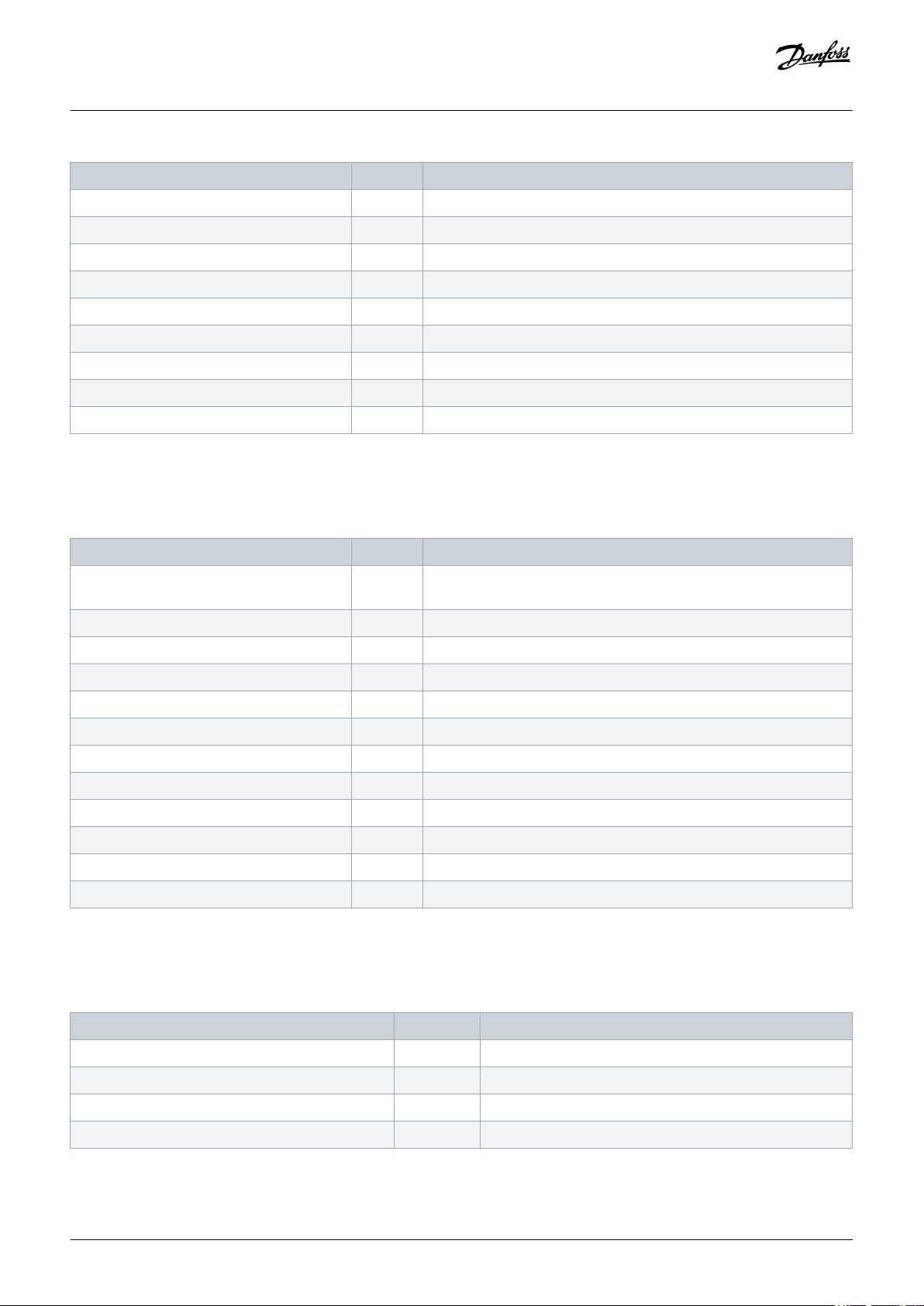
4.4 Lifting the Enclosure Sizes MR8 and MR9
Context:
The weights of AC drives of different enclosure sizes are different. It can be necessary for you to use a lifting device to move the drive
from its package. See the weights of the different enclosure sizes in table 23.
WA RN IN G
LIFTING HEAVY LOAD
Not following the safe lifting instructions can result in death or serious injury.
Do not walk under suspended loads. Use lifting devices that are appropriate for the weight of the unit. Use the
-
recommended lifting method.
22 | Danfoss A/S © 2019.05
AQ298036140958en-000101 / DPD01711
≤45°
e30bh138.10
Operating Guide | VACON® 100 Wall-mounted Drives
Procedure
1. Remove the drive from the pallet where it was bolted to.
2. Use a lifting device that is sufficiently strong for the weight of the drive.
3. Put the lifting hooks symmetrically in a minimum of 2 holes.
A The maximum lifting angle is 45 °.
Receiving the Delivery
Illustration 2: Maximum Lifting Angle
4.5 Using the Product Modified Label
Context:
In the accessories bag, there is also a "product modified" label. The function of the label is to tell the service personnel about the
changes that are made in the AC drive.
Danfoss A/S © 2019.05
AQ298036140958en-000101 / DPD01711| 23

e30bg773.10
Product modified
Date:
Date:
Date:
Operating Guide | VACON® 100 Wall-mounted Drives
Illustration 3: The Product Modified Label
Procedure
1. Attach the label on the side of the AC drive to know where to find it.
2. If changes are made in the AC drive, write the change on the label.
Receiving the Delivery
24 | Danfoss A/S © 2019.05
AQ298036140958en-000101 / DPD01711
A
B
D
A
C
E
e30bh167.10
Operating Guide | VACON® 100 Wall-mounted Drives
Mounting
5 Mounting
5.1 Wall-mounting Requirements
Install the AC drive in a vertical position on the wall.
If you install the drive in a horizontal position, there is no protection against drops of water that fall vertically. Use the same mounting
points as with vertical installation and pay special attention to cooling requirements (see 5.3.2 Cooling).
Install the AC drive with the screws and other components included in the delivery.
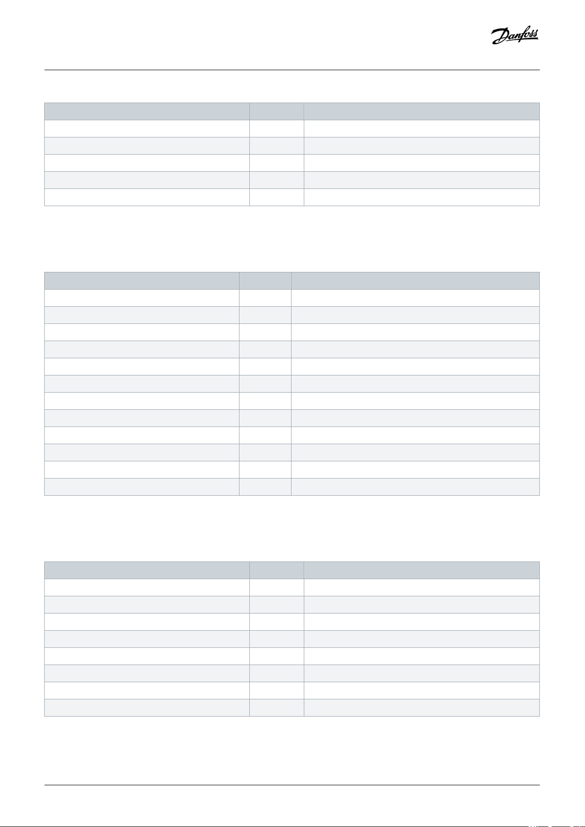
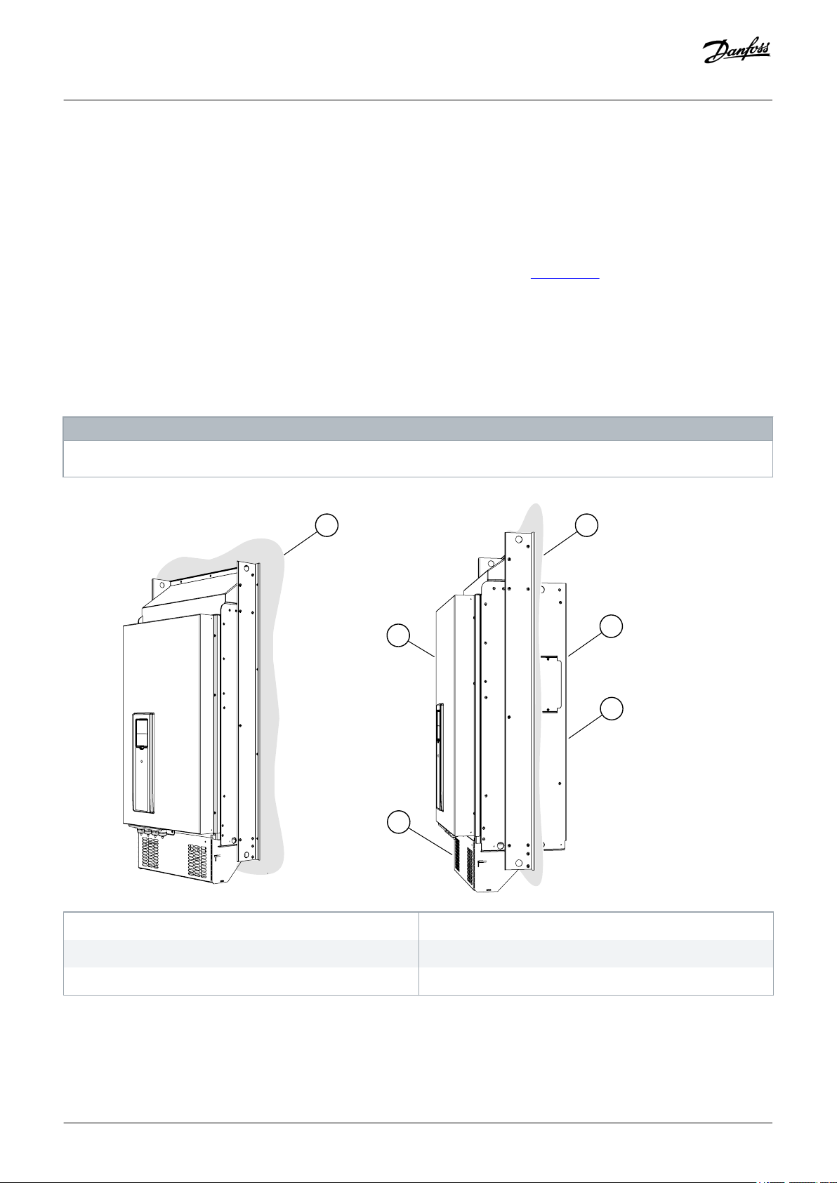
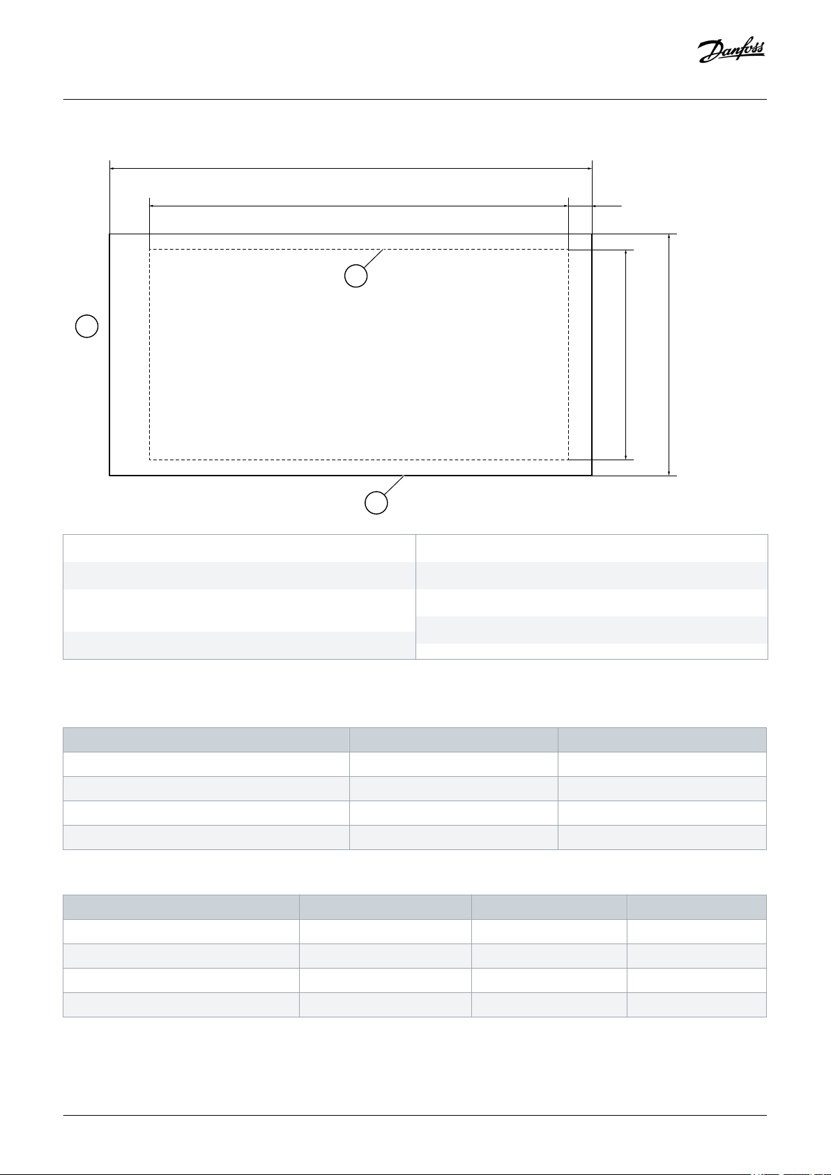
5.2 Flange-mounting Requirements
You can also install the AC drive into the cabinet wall with a flange mounting option.
NO TI CE
The protection classes are different in different sections of the drive.
A The cabinet wall or other surface
C The rear
E IP54/UL Type 12
Illustration 4: Example of Flange Mounting
Danfoss A/S © 2019.05
B The front
D IP21/UL Type 1
AQ298036140958en-000101 / DPD01711| 25
G
F
A E
B
D
C
H
e30bh168.10
Operating Guide | VACON® 100 Wall-mounted Drives
Mounting
A The height of the opening
C The height of the drive
E The distance between the bottom of the drive and the
bottom of the opening
G The outline of the drive
Illustration 5: Dimensions of the Opening and Drive Outline with Flange
Table 10: The Dimensions of the Drive, MR4 to MR7, in mm (in inch)
Enclosure size C D
MR4 357 (14.1) 152 (6.0)
MR5 454 (17.9) 169 (6.7)
MR6 580 (22.8) 220 (8.7)
MR7 680 (26.8) 286 (11.3)
Table 11: The Dimensions of the Opening for the Flange Mounting, MR4 to MR7, in mm (in inch)
Enclosure size A B E
MR4 315 (12.4) 137 (5.4) 24 (0.9)
B The width of the opening
D The width of the drive
F The outline of the opening
H The top of the drive
MR5 408 (16.1) 152 (6.0) 23 (0.9)
MR6 541 (21.3) 203 (8.0) 23 (0.9)
MR7 655 (25.8) 240 (9.4) 13 (0.5)
26 | Danfoss A/S © 2019.05
AQ298036140958en-000101 / DPD01711
A
D
A
B
B
C
e30bg010.10
Operating Guide | VACON® 100 Wall-mounted Drives
Mounting
5.3 Cooling Requirements
5.3.1 General Cooling Requirements
The AC drive produces heat in operation. The fan moves air and decreases the temperature of the drive. Make sure that there is
sufficiently free space around the drive. Some free space is also necessary for maintenance.
Make sure that the temperature of the cooling air does not go above the maximum ambient operating temperature or below the
minimum ambient operating temperature of the drive.
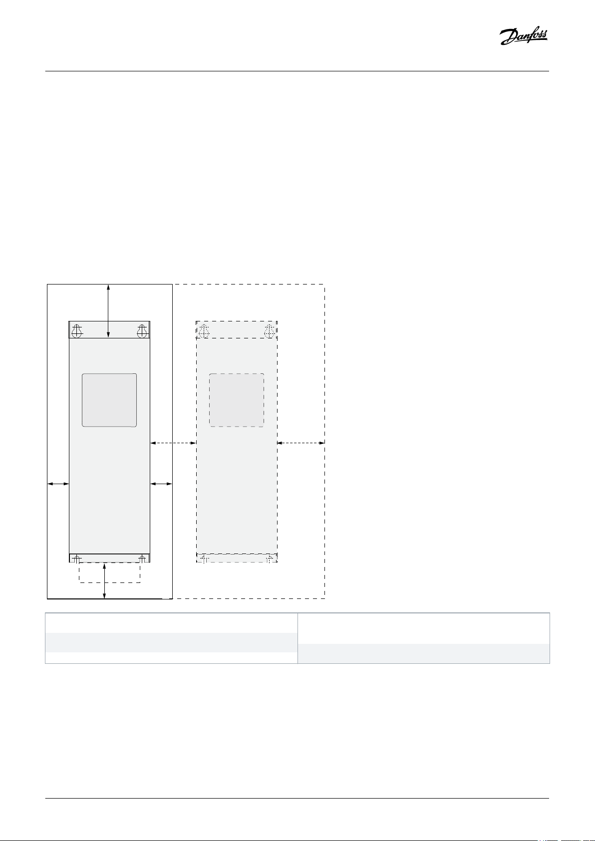
5.3.2 Cooling
A The clearance around the drive (see also B and C)
C The free space above the drive
Illustration 6: Installation Space
Danfoss A/S © 2019.05
B The distance from a drive to a second drive, or the distance to
the cabinet wall
D The free space below the drive
AQ298036140958en-000101 / DPD01711| 27

Operating Guide | VACON® 100 Wall-mounted Drives
Table 12: Minimum Clearances around the AC Drive in mm (in inch)
Mounting
Enclosure size
(1)
A
(1)
B
C D
MR4 20 (0.8) 20 (0.8) 100 (3.9) 50 (2.0)
MR5 20 (0.8) 20 (0.8) 120 (4.7) 60 (2.4)
MR6 20 (0.8) 20 (0.8) 160 (6.3) 80 (3.1)
MR7 20 (0.8) 20 (0.8) 250 (9.8) 100 (3.9)
MR8 20 (0.8) 20 (0.8) 300 (11.8) 150 (5.9)
MR9 20 (0.8) 20 (0.8) 350 (13.8) 200 (7.9)
1
For a drive with IP54/UL Type 12, the minimum clearances A and B are 0 mm/0 in.
28 | Danfoss A/S © 2019.05
AQ298036140958en-000101 / DPD01711
e30bh172.10
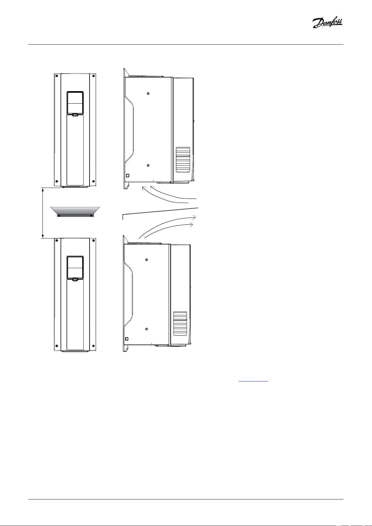
C+D
Operating Guide | VACON® 100 Wall-mounted Drives
Mounting
Illustration 7: Installation Space when Drives Are Installed on Top of Each Other
• If many AC drives are installed above each other, the necessary free space is C + D (see illustration 6).
• Make also sure that the outlet air from the lower drive goes to a different direction than the air intake of the top drive. To do this,
attach a metal plate to the cabinet wall between the drives.
• When the drives are installed in a cabinet, make sure to prevent recirculation of air.
Danfoss A/S © 2019.05
AQ298036140958en-000101 / DPD01711| 29

Operating Guide | VACON® 100 Wall-mounted Drives
5.3.3 Necessary Quantity of Cooling Air
Table 13: The Necessary Quantity of Cooling Air
Mounting
Enclosure size
MR4 45 26
MR5 75 44
MR6 190 112
MR7 185 109
MR8 335 197
MR9 620 365
The quantity of cooling air, m3/h
The quantity of cooling air, CFM
30 | Danfoss A/S © 2019.05
AQ298036140958en-000101 / DPD01711

A
B
C
e30bh206.10
U/T1
V/T2
W/T3
L1
L2
L3
DC-
DC+/R+
R-
Operating Guide | VACON® 100 Wall-mounted Drives
Electrical Installation
6 Electrical Installation
6.1 Cable Connections
The mains cables are connected to terminals L1, L2, and L3. The motor cables are connected to terminals U, V, and W.
A The control panel
C The power unit
Illustration 8: Principal Connection Diagram
For EMC-compliant installation, see 6.2 EMC-compliant Installation.
6.1.1 General Cable Requirements
Use cables with a minimum heat resistance of +70 °C (158 °F). In the selection of the cables and the fuses, refer to the nominal output
current of the drive. Find the nominal output current on the nameplate.
For information on how to make the cable installation to comply with the UL standards, see 6.1.2 UL Standards on Cabling.
These instructions are valid only for processes that have 1 motor and 1 cable connection from the AC drive to the motor. In other
conditions, speak to the manufacturer to get more information.
B The control unit
Danfoss A/S © 2019.05
AQ298036140958en-000101 / DPD01711| 31

Operating Guide | VACON® 100 Wall-mounted Drives
Electrical Installation
6.1.2 UL Standards on Cabling
To comply with the UL (Underwriters Laboratories) regulations, use a UL-approved copper wire with a minimum heat resistance of
60 °C or 75 °C (140 °F or 167 °F).
To comply with the standards, use cables with +90 °C (194 °F) heat resistance for the 500 V drive.
Use Class 1 wire only.
When the drive has Class T and J fuses, it can be used on a circuit that gives a maximum of 100 000 rms symmetrical amperes, and a
maximum of 600 V.
The integral solid-state short-circuit protection does not give a branch circuit protection. Obey the National Electric Code and any
additional local codes to get the branch circuit protection. Only fuses give the branch circuit protection.
For the tightening torques of the terminals, see 10.5 Tightening Torques of the Terminals.
6.1.3 Cable Selection and Dimensioning
Find the typical sizes and types of cables used with the AC drive in the tables in 10.3.1 List of Cable and Fuse Size Information. In the
selection of cables, refer to local regulations, cable installation conditions, and cable specification.
The dimensions of the cables must comply with the requirements of the standard IEC60364-5-52.
• The cables must be PVC-isolated.
• The maximum ambient temperature is +30 °C.
• The maximum temperature of the cable surface is +70 °C.
• Use only cables with a concentric copper shield.
• The maximum number of parallel cables is 9.
When using parallel cables, make sure to obey the requirements of the cross-sectional area and the maximum number of cables.
For important information on the requirements of the grounding conductor, see
For the correction factors for each temperature, see the standard IEC60364-5-52.
6.3 Grounding.
6.1.4 Cable Selection and Dimensioning, North America
Find the typical sizes and types of cables used with the AC drive in the tables in 10.3.1 List of Cable and Fuse Size Information. In the
selection of cables, refer to local regulations, cable installation conditions, and cable specification.
The dimensions of the cables must comply with the requirements of the Underwriters Laboratories UL 61800-5-1.
• The cables must be PVC-isolated.
• The maximum ambient temperature is +86 °F.
• The maximum temperature of the cable surface is +158 °F.
• Use only cables with a concentric copper shield.
• The maximum number of parallel cables is 9.
When using parallel cables, make sure to obey the requirements of the cross-sectional area and the maximum number of cables.
For important information on the requirements of the grounding conductor, see the Underwriters Laboratories standard UL 61800-5-1.
32 | Danfoss A/S © 2019.05
AQ298036140958en-000101 / DPD01711

Operating Guide | VACON® 100 Wall-mounted Drives
For the correction factors for each temperature, see the instructions of the Underwriters Laboratories UL 61800-5-1.
Electrical Installation
6.1.5 Fuse Selection
We recommend the fuse type gG/gL (IEC 60269-1). To make a selection of the fuse voltage rating, refer to the mains. Refer also to local
regulations, cable installation conditions, and cable specification. Do not use larger fuses than what is recommended.
Find the recommended fuses in tables in 10.3.1 List of Cable and Fuse Size Information.
Make sure that the operation time of the fuse is less than 0.4 s. The operation time agrees with the fuse type and the impedance of the
supply circuit. For more information on faster fuses, speak to the manufacturer. The manufacturer can also recommend some aR (UL
recognized, IEC 60269-4) and gS (IEC 60269-4) fuse ranges.
6.1.6 Fuse Selection, North America
We recommend the fuse class T (UL & CSA). To make a selection of the fuse voltage rating, refer to the mains. Refer also to local
regulations, cable installation conditions, and cable specification. Do not use larger fuses than what is recommended.
Find the recommended fuses in tables in 10.3.1 List of Cable and Fuse Size Information.
Make sure that the operation time of the fuse is less than 0.4 s. The operation time agrees with the fuse type and the impedance of the
supply circuit. For more information on faster fuses, speak to the manufacturer. The manufacturer can also recommend some highspeed Class J (UL & CSA) and aR (UL recognised) fuse ranges.
The solid-state short circuit protection does not supply protection for the branch circuit of the AC drive. To supply the branch circuit
protection, refer to the National Electric Code and the local regulations. Do not use other devices than fuses to supply branch circuit
protection.
6.1.7 Brake Resistor Cables
VACON® 100 wall-mounted drives have terminals for an optional external brake resistor. These terminals are identified with R+ and R(in MR4) or DC+/R+ and R- (in MR5, MR6, MR7, MR8, and MR9). Find the dimensions that we recommend for the brake resistor cables in
the tables linked in 10.3.1 List of Cable and Fuse Size Information. See also the brake resistor ratings in 10.8.1 Brake Resistor Ratings.
CA UT IO N
SHOCK HAZARD FROM MULTI-CONDUCTOR CABLES
With a multi-conductor cable, the conductors that are not connected can cause an accidental contact with a conducting
component.
If a multi-conductor cable is used, cut off all conductors that are not connected.
-
The enclosure sizes MR7, MR8, and MR9 have the brake chopper only if their type code has the code +DBIN. The frames MR4, MR5, and
MR6 have the brake chopper as standard.
NO TI CE
The VACON® 100 FLOW and HVAC software do not have the dynamic braking or the brake resistor functions.
Danfoss A/S © 2019.05
AQ298036140958en-000101 / DPD01711| 33

A
C
B
e30bg079.10
Operating Guide | VACON® 100 Wall-mounted Drives
Electrical Installation
6.2 EMC-compliant Installation
For cable selections in different EMC levels, see table 14.
To comply with the EMC levels, use a grommet when installing the motor cable at the two ends. For the EMC level C2, it is necessary to
have a 360º grounding of the shield with grommets in the motor end.
Table 14: Recommendations for Cables
Cable
type
Motor cable
Mains cable
Control
cable
1
st
1
environment
2
2nd environment
Category C2
(1)
A symmetrical power cable with a compact low-impe-
Category C3
A symmetrical power cable with a concentric protection wire.
(2)
Category C4
(2)
dance shield.
A cable for the specified mains voltage.
A cable for the specified mains voltage.
We recommend an MCMK cable. See illustration 9.
We recommend an MCCMK, or an EMCMK cable. See
illustration 9.
We recommend that the cable transfer impedance
(1–30 MHz) is a maximum of 100 mΩ/m.
A power cable for a fixed installation.
A cable for the specified mains voltage.
A shielded cable is not necessary.
We recommend an MCMK cable.
A shielded cable with a compact low-impedance shield, for example a JAMAK, or an SAB/ÖZCuY-O cable.
For the definitions of EMC protection levels, see IEC/EN 61800-3 + A1.
A The PE conductor and the shield
C The shield
Illustration 9: Cables with PE Conductors
B The PE conductors
34 | Danfoss A/S © 2019.05
AQ298036140958en-000101 / DPD01711

Operating Guide | VACON® 100 Wall-mounted Drives
In all the enclosure sizes, to comply with the EMC standards, use the default values of the switching frequencies.
If installing a safety switch, make sure that the EMC protection continues from the start of the cables until their ends.
Electrical Installation
The drive must obey the standard IEC 61000-3-12. To obey it, the short circuit power SSC must be a minimum of 120 R
interface point between mains and the public mains. Make sure to connect the drive and the motor to mains with a short circuit power
SSC that is a minimum of 120 R
. If necessary, contact the mains operator.
SCE
SCE
at the
6.2.1 Installation in a Corner-grounded Network
Corner grounding can be used in these conditions:
• Enclosure sizes MR4-MR6 with mains voltage 208–240 V up to 2000 m
• Enclosure sizes MR7-MR9 with a rating of 75–310 A and with mains voltage 208–240 V
Enclosure sizes MR7-MR9 with a rating of 72–385 A and with mains voltage 380–500 V
Do not use corner grounding in these conditions:
• Enclosure sizes MR4-MR6 with a rating of 3.4–61 A and with mains voltage 380–500 V
• Drives with mains voltage 525–600 V or 525–690 V
When using corner grounding, the drive must have EMC protection level C4. To change the EMC protection level from C2 or C3 to C4,
see instructions in 6.6 Installation in an IT System.
6.3 Grounding
Ground the AC drive in accordance with applicable standards and directives.
CA UT IO N
DAMAGE TO THE AC DRIVE FROM INSUFFICIENT GROUNDING
Not using a grounding conductor can damage the drive.
Make sure that the AC drive is always grounded with a grounding conductor that is connected to the grounding terminal
-
that is identified with the PE symbol.
WA RN IN G
LEAKAGE CURRENT HAZARD
Leakage currents exceed 3.5 mA. Failure to ground the drive properly can result in death or serious injury.
Ensure the correct grounding of the equipment by a certified electrical installer.
-
The standard EN 61800-5-1 tells that 1 or more of these conditions for the protective circuit must be true.
The connection must be fixed.
• The protective earthing conductor must have a cross-sectional area of minimum 10 mm2 Cu or 16 mm2 Al. OR
• There must be an automatic disconnection of the mains, if the protective earthing conductor breaks. OR
• There must be a terminal for a second protective earthing conductor in the same cross-sectional area as the first protective
earthing conductor.
Danfoss A/S © 2019.05
AQ298036140958en-000101 / DPD01711| 35

Operating Guide | VACON® 100 Wall-mounted Drives
Electrical Installation
Cross-sectional area of the phase conductors (S) [mm2]
S ≤ 16 S
16 < S ≤ 35 16
35 < S S/2
The values of the table are valid only if the protective earthing conductor is made of the same metal as the phase conductors. If this is
not so, the cross-sectional area of the protective earthing conductor must be determined in a manner that produces a conductance
equivalent to that which results from the application of this table.
The cross-sectional area of each protective earthing conductor that is not a part of the mains cable or the cable enclosure, must be a
minimum of:
• 2.5 mm2 if there is mechanical protection, and
• 4 mm2 if there is not mechanical protection. With cord-connected equipment, make sure that the protective earthing conductor in
the cord is the last conductor to be interrupted, if the strain-relief mechanism breaks.
Obey the local regulations on the minimum size of the protective earthing conductor.
The minimum cross-sectional area of the protective earthing
conductor in question [mm2]
NO TI CE
MALFUNCTION OF FAULT CURRENT PROTECTIVE SWITCHES
Because there are high capacitive currents in the AC drive, it is possible that the fault current protective switches do not
operate correctly.
NO TI CE
VOLTAGE WITHSTAND TESTS
Doing voltage withstand tests can damage the drive.
Do not do voltage withstand tests on the AC drive. The manufacturer has already done the tests.
-
WA RN IN G
SHOCK HAZARD FROM PE CONDUCTOR
The drive can cause a DC current in the PE conductor. Failure to use a residual current-operated protective (RCD) device Type B
or a residual current-operated monitoring (RCM) device can lead to the RCD not providing the intended protection and
therefore can result in death or serious injury.
Use a type B RCD or RCM device on the mains side of the drive.
-
6.4 Get Access and Locate the Terminals
6.4.1 Get Access and Locate the Terminals for MR4-MR7
Context:
Follow these instructions to open the AC drive for installing the cables, for example.
36 | Danfoss A/S © 2019.05
AQ298036140958en-000101 / DPD01711

M4x55
e30bh222.10
M4x8
e30bh223.10
Operating Guide | VACON® 100 Wall-mounted Drives
Procedure
1. Open the cover of the AC drive.
2. Remove the screws of the cable cover. Remove the cable cover. Do not open the cover of the power unit.
Electrical Installation
3. Locate the terminals.
Danfoss A/S © 2019.05
AQ298036140958en-000101 / DPD01711| 37

A B C
e30bh286.10
Operating Guide | VACON® 100 Wall-mounted Drives
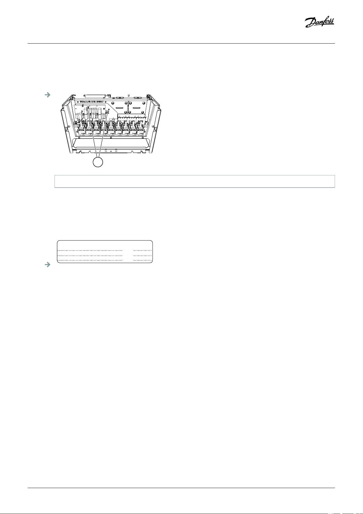
Electrical Installation
A Mains terminals
C Motor terminals
Illustration 10: Locating the Terminals, MR4-MR7
B Brake resistor terminals
6.4.2 Get Access and Locate the Terminals for MR8
Context:
Follow these instructions to open the AC drive for installing the cables, for example.
38 | Danfoss A/S © 2019.05
AQ298036140958en-000101 / DPD01711

e30bh251.10
M4x8
e30bh252.10
M4x8
Operating Guide | VACON® 100 Wall-mounted Drives
Procedure
1. Open the cover of the AC drive.
2. Remove the cable cover.
Electrical Installation
3. Remove the cable entry plate.
4. Remove the EMC shield plate.
Danfoss A/S © 2019.05
AQ298036140958en-000101 / DPD01711| 39

M5
M4x8
A
e30bh253.10
L1
U V W
L2 L3 DC-
DC+
R+
R-
e30bh254.10
Operating Guide | VACON® 100 Wall-mounted Drives
A The wing nut
Electrical Installation
Illustration 11: Removing the EMC Shield Plate, MR8
5. Find the motor terminals. The location of the terminals is different than usually, especially in MR8.
6.4.3 Get Access and Locate the Terminals for MR9
Context:
Follow these instructions to open the AC drive for installing the cables, for example.
40 | Danfoss A/S © 2019.05
AQ298036140958en-000101 / DPD01711

M4x10
e30bh244.10
M4x8
e30bh245.10
Operating Guide | VACON® 100 Wall-mounted Drives
Procedure
1. Open the cover of the AC drive.
Electrical Installation
2. Remove the cable cover.
3. Remove the cable entry plate.
Danfoss A/S © 2019.05
AQ298036140958en-000101 / DPD01711| 41

e30bh246.10
M5x10
e30bh247.10
M4x8
Operating Guide | VACON® 100 Wall-mounted Drives
4. Loosen the screws and remove the sealing plate.
Electrical Installation
5. Remove the EMC shield plate.
42 | Danfoss A/S © 2019.05
AQ298036140958en-000101 / DPD01711

e30bh248.10
L1
U V W
L2
L3 DC-
DC+
R+
R-
e30bh249.10
Operating Guide | VACON® 100 Wall-mounted Drives
6. Find the motor terminals. The location of the terminals is different than usually, especially in MR8.
Electrical Installation
6.5 Installation of Cables
6.5.1 Additional Instructions for Cable Installation
• Before starting, make sure that none of the components of the AC drive is live. Read carefully the warnings in Safety section.
• Make sure that the motor cables are sufficiently far from other cables.
• The motor cables must go across other cables at an angle of 90°.
• If it is possible, do not put the motor cables in long parallel lines with other cables.
• If the motor cables are in parallel with other cables, obey the minimum distances (see table 15).
• The distances are also valid between the motor cables and the signal cables of other systems.
• The maximum lengths of shielded motor cables are 100 m/328 ft (for MR4), 150 m/492 ft (for MR5 and MR6), and 200 m/656 ft (for
MR7, MR8, and MR9).
• If the cable insulation checks are necessary, see
Table 15: Minimum Distances between Cables
The distance between cables [m]
0.3 ≤ 50 1.0 ≤ 164.0
1.0 ≤ 300 3.3 ≤ 656.1
The length of the shielded cable
[m]
8.3 Measuring the Cable and Motor Insulation.
The distance between cables [ft]
The length of the shielded cable
[ft]
Danfoss A/S © 2019.05
AQ298036140958en-000101 / DPD01711| 43

Operating Guide | VACON® 100 Wall-mounted Drives
Electrical Installation
6.5.2 Installing the Cables, MR4-MR7
Context:
Follow these instructions to install the cables and cable accessories. For information on how to comply with the UL regulations in cable
installation, see 6.1.2 UL Standards on Cabling.
Prerequisites:
Make sure that the delivery contains all necessary components. For the installation, the contents of the accessories bag is needed, see
4.2 Accessories.
Open the covers according to instructions in 6.4.1 Get Access and Locate the Terminals for MR4-MR7.
44 | Danfoss A/S © 2019.05
AQ298036140958en-000101 / DPD01711

A B C
e30bh224.10
e30bg086.10
Operating Guide | VACON® 100 Wall-mounted Drives
Procedure
1. Strip the motor cable, the mains cable, and the brake resistor cable. See 10.4 Cable Stripping Lengths.
The VACON® 100 FLOW and HVAC software do not have the dynamic braking or the brake resistor functions.
2. Put the grommets in the openings of the cable entry plate. These parts are included in the package.
3. Put the cables in the openings of the cable entry plate.
4. Cut the grommets open to move the cables through them.
A Do not cut the grommet openings wider than what is necessary for the used cables.
B If the grommets fold in when putting the cable, pull the cable back to make the grommets straight.
Electrical Installation
A The mains cable
B The brake cable
C The motor cable
Illustration 12: Installing Cables through Grommets
5. With the protection rating IP54, the connection between the grommet and the cable must be tight. Pull the first bit of the cable out
of the grommet so that is stays straight. If this is not possible, make the connection tight with some insulation tape or a cable tie.
6. Remove the grounding clamps for cable shield and the grounding clamps for grounding conductor. The tightening torque is 2.2
Nm or 19.5 lb-in.
Danfoss A/S © 2019.05
AQ298036140958en-000101 / DPD01711| 45

M4x16
(2.2 Nm)
e30bh225.10
e30bh226.10
Operating Guide | VACON® 100 Wall-mounted Drives
Electrical Installation
7. Put the cable entry plate with the cables into the groove on the frame of the drive.
8. Connect the cables. See the correct tightening torques in 10.5 Tightening Torques of the Terminals.
A Expose the shield of all the 3 cables to make a 360-degree connection with the grounding clamps for cable shield.
B Connect the phase conductors of the mains cable and of the motor cable, and the conductors of the brake resistor cable into
the correct terminals.
C Attach the grounding conductor of each cable to a grounding terminal with a grounding clamp for grounding conductor.
D Make sure that the external grounding conductor is connected to the grounding bar. See
6.3 Grounding.
46 | Danfoss A/S © 2019.05
AQ298036140958en-000101 / DPD01711

C
D
F
C
B
A
e30bh227.10
E
e30bh228.10
= M5; 2 Nm
Operating Guide | VACON® 100 Wall-mounted Drives
Electrical Installation
A The grounding clamp for cable shield
C The grounding terminal
E The brake resistor cable
Illustration 13: Connecting the Stripped Cables
B The terminals
D The mains cable
F The motor cable
9. Make sure that the grounding conductor is connected to the motor and also to the terminals that are identified with the PE symbol.
A To comply with the requirements of the standard EN 61800-5-1, obey the instructions in 6.3 Grounding.
B If a double grounding is necessary, use the grounding terminal under the drive. Use an M5 screw and tighten it to 2.0 Nm or
17.7 lb-in.
10. Attach again the cable cover.
Danfoss A/S © 2019.05
AQ298036140958en-000101 / DPD01711| 47

e30bh229.10
e30bh230.10
Operating Guide | VACON® 100 Wall-mounted Drives
Electrical Installation
11. Close the cover of the drive.
6.5.3 Installing the Cables, MR8-MR9
Context:
Follow these instructions to install the cables and cable accessories. For information on how to comply with the UL regulations in cable
installation, see 6.1.2 UL Standards on Cabling.
Prerequisites:
Make sure that the delivery contains all necessary components. For the installation, the contents of the accessories bag is needed, see
4.2 Accessories.
Open the covers according to instructions in 6.4.2 Get Access and Locate the Terminals for MR8 and 6.4.3 Get Access and Locate the
Terminals for MR9.
48 | Danfoss A/S © 2019.05
AQ298036140958en-000101 / DPD01711

e30bh277.10
e30bh278.10
Operating Guide | VACON® 100 Wall-mounted Drives
Procedure
1. Strip the motor cable, the mains cable, and the brake resistor cable. See 10.4 Cable Stripping Lengths.
The VACON® 100 FLOW and HVAC software do not have the dynamic braking or the brake resistor functions.
2. Cut the grommets open to move the cables through them.
A Do not cut the grommet openings wider than what is necessary for the used cables.
B If the grommets fold in when putting the cable, pull the cable back to make the grommets straight.
Electrical Installation
3. Attach the grommet and the cable so that the frame of the drive goes into the groove of the grommet.
A With the protection rating IP54 (UL Type 12), the connection between the grommet and the cable must be tight. Pull the first
bit of the cable out of the grommet so that it stays straight.
B If this is not possible, make the connection tight with some insulation tape or a cable tie.
Danfoss A/S © 2019.05
AQ298036140958en-000101 / DPD01711| 49

e30bh279.10
e30bh280.10
Operating Guide | VACON® 100 Wall-mounted Drives
Electrical Installation
4. If thick cables are used, put the cable insulators in between the terminals to prevent contact between the cables.
5. Connect the cables. See the correct tightening torques in 10.5 Tightening Torques of the Terminals.
A Connect the phase conductors of the mains cable and of the motor cable into the correct terminals. If a brake resistor cable is
used, connect its conductors into the correct terminals.
B Attach the grounding conductor of each cable to a grounding terminal with a grounding clamp for grounding conductor.
C Make sure that the external grounding conductor is connected to the grounding bar. See
6.3 Grounding.
50 | Danfoss A/S © 2019.05
AQ298036140958en-000101 / DPD01711

A
e30bh255.10
A
e30bh250.10
Operating Guide | VACON® 100 Wall-mounted Drives
Electrical Installation
A The grounding connection
Illustration 14: Connecting the Cables, MR8
A The grounding connection
Illustration 15: Connecting the Cables, MR9
6. If many cables are used on one connector, put the cable lugs on top of each other.
Danfoss A/S © 2019.05
AQ298036140958en-000101 / DPD01711| 51

A
C
B
e30bh281.10
e30bh282.10
Operating Guide | VACON® 100 Wall-mounted Drives
7. Expose the shield of all 3 cables to make a 360° connection with the grounding clamp for cable shield.
Electrical Installation
8. Make sure that the grounding conductor is connected to the motor and also to the terminals that are identified with the PE symbol.
A To comply with the requirements of the standard EN 61800-5-1, obey the instructions in 6.3 Grounding.
B Connect the protective conductor to one of the screw connectors with a cable shoe and an M8 screw.
52 | Danfoss A/S © 2019.05
AQ298036140958en-000101 / DPD01711

e30bh285.10
Operating Guide | VACON® 100 Wall-mounted Drives
9. For MR8, attach the EMC shield plate, the cable entry plate, and the cable cover.
10. For MR9, attach the EMC shield plate, the sealing plate, the cable entry plate, and the cable cover.
11. Close the cover of the drive.
Electrical Installation
6.6 Installation in an IT System
If your mains is impedance-grounded (IT), the AC drive must have the EMC protection level C4. If the drive has the EMC protection level
C2 or C3, it is necessary to change it to C4. To do this, remove the EMC jumpers.
WA RN IN G
SHOCK HAZARD FROM THE COMPONENTS
The components of the drive are live when the drive is connected to mains.
Do not make changes in the AC drive when it is connected to mains.
-
NO TI CE
DAMAGE TO THE AC DRIVE FROM INCORRECT EMC LEVEL
The EMC level requirements for the AC drive depend on the installation environment. An incorrect EMC level can damage the
drive.
Before connecting the AC drive to the mains, make sure that the EMC level of the AC drive is correct for the mains.
-
NO TI CE
For a 600 and 690V product that is configured for a C4 installation on IT network, the maximum switching frequency is limited
to the default 2 kHz.
6.6.1 Installing the AC drive in an IT System, MR4-MR6
Context:
Use these instructions to change the EMC protection of the AC drive to level C4.
Prerequisites:
Open the cover of the AC drive (for MR4-MR6) and remove the cable cover (for MR4-MR5) as instructed in
the Terminals for MR4-MR7.
6.4.1 Get Access and Locate
Danfoss A/S © 2019.05
AQ298036140958en-000101 / DPD01711| 53

e30bh297.10
MR4 MR5
e30bh299.10
MR6, 200–500 V
MR6, 600/690 V
e30bh301.10
Operating Guide | VACON® 100 Wall-mounted Drives
Procedure
1. Find the EMC jumpers that connect the RFI filters to ground.
Electrical Installation
2. To disconnect the RFI filters from ground, remove the EMC jumpers. Pull the EMC jumper out with the tool.
54 | Danfoss A/S © 2019.05
AQ298036140958en-000101 / DPD01711

e30bg773.10
Product modified
Date:
Date:
Date:
Operating Guide | VACON® 100 Wall-mounted Drives
Electrical Installation
3. For MR4 and MR5, attach the cable cover.
4. Close the cover of the AC drive.
5. After the change, write "The EMC level was changed" and the date on the "product modified" label. If the label is not yet attached,
attach it on the drive near the nameplate.
6.6.2 Installing the AC drive in an IT System, MR7
Context:
Use these instructions to change the EMC protection of the AC drive to level C4.
Prerequisites:
Open the cover of the AC drive and remove the cable cover (for 600/690 V) as instructed in
for MR4-MR7.
6.4.1 Get Access and Locate the Terminals
Danfoss A/S © 2019.05
AQ298036140958en-000101 / DPD01711| 55

e30bh302.10
e30bh303.10
Operating Guide | VACON® 100 Wall-mounted Drives
Procedure for 200–500 V
1. Find the EMC box. To get access to the EMC jumper, remove the cover of the EMC box.
2. Remove the EMC jumper. Attach the cover of the EMC box again.
Electrical Installation
3. Find the DC grounding busbar between the terminals R- and U. To remove the busbar from the frame, remove the M4 screw.
56 | Danfoss A/S © 2019.05
AQ298036140958en-000101 / DPD01711

L1
L2 L3
DC-
R-
DC+
R+
U
V
W
T1
T2 T3
e30bh304.10
e30bg773.10
Product modified
Date:
Date:
Date:
e30bh306.10
e30bg773.10
Product modified
Date:
Date:
Date:
Operating Guide | VACON® 100 Wall-mounted Drives
Electrical Installation
4. Close the cover of the AC drive.
5. After the change, write "The EMC level was changed" and the date on the "product modified" label. If the label is not yet attached,
attach it on the drive near the nameplate.
Procedure for 600/690 V
1. Remove the EMC jumper.
2. Attach the cable cover.
3. Close the cover of the AC drive.
4. After the change, write "The EMC level was changed" and the date on the "product modified" label. If the label is not yet attached,
attach it on the drive near the nameplate.
Danfoss A/S © 2019.05
AQ298036140958en-000101 / DPD01711| 57

Operating Guide | VACON® 100 Wall-mounted Drives
6.6.3 Installing the AC drive in an IT System, MR8
Context:
Use these instructions to change the EMC protection of the AC drive to level C4.
Prerequisites:
Open the cover of the AC drive and remove the cable cover as instructed in
6.4.2 Get Access and Locate the Terminals for MR8.
Electrical Installation
58 | Danfoss A/S © 2019.05
AQ298036140958en-000101 / DPD01711

A
e30bh307.10
A
B
e30bh308.10
Operating Guide | VACON® 100 Wall-mounted Drives
Procedure
1. Find the EMC box. To get access to the EMC jumper, remove the cover of the EMC box.
A The EMC jumper
Illustration 16: Removing the EMC Box Cover, MR8
2. Remove the EMC jumper. Attach the cover of the EMC box again.
3. Find the grounding arm and push it down.
Electrical Installation
A The grounding arm is up B The grounding arm is down (level C4)
Illustration 17: Finding the Grounding Arm, MR8
4. Attach the cable cover.
5. Close the cover of the AC drive.
6. After the change, write "The EMC level was changed" and the date on the "product modified" label. If the label is not yet attached,
attach it on the drive near the nameplate.
Danfoss A/S © 2019.05
AQ298036140958en-000101 / DPD01711| 59

e30bg773.10
Product modified
Date:
Date:
Date:
Operating Guide | VACON® 100 Wall-mounted Drives
6.6.4 Installing the AC drive in an IT System, MR9
Context:
Use these instructions to change the EMC protection of the AC drive to level C4.
Prerequisites:
Open the cover of the AC drive as instructed in
6.4.3 Get Access and Locate the Terminals for MR9.
Electrical Installation
60 | Danfoss A/S © 2019.05
AQ298036140958en-000101 / DPD01711

e30bh375.10
e30bh376.10
e30bg773.10
Product modified
Date:
Date:
Date:
Operating Guide | VACON® 100 Wall-mounted Drives
Procedure for EMC Jumper 1, MR9A
1. Remove the cover of the fan.
2. In IP54, also remove the fan.
3. Loosen the screws of the cover plate and remove it.
4. Find the place of the jumper behind the fan. Remove the EMC jumper.
Electrical Installation
5. Attach the cover plate.
6. In IP54, attach the fan.
7. Attach the cover of the fan.
8. After the change, write "The EMC level was changed" and the date on the "product modified" label. If the label is not yet attached,
attach it on the drive near the nameplate.
Danfoss A/S © 2019.05
AQ298036140958en-000101 / DPD01711| 61

e30bh377.10
e30bg773.10
Product modified
Date:
Date:
Date:
Operating Guide | VACON® 100 Wall-mounted Drives
Electrical Installation
Procedure for EMC Jumper 1, MR9B
1. Remove the EMC jumper.
2. After the change, write "The EMC level was changed" and the date on the "product modified" label. If the label is not yet attached,
attach it on the drive near the nameplate.
62 | Danfoss A/S © 2019.05
AQ298036140958en-000101 / DPD01711
A
e30bh378.10
e30bg773.10
Product modified
Date:
Date:
Date:
Operating Guide | VACON® 100 Wall-mounted Drives
Electrical Installation
Procedure for EMC Jumpers 2 + 3, MR9A and MR9B
1. Remove the cover of the extension box, the touch shield, and the I/O plate with the I/O grommet plate.
2. Find the 2 EMC jumpers on the EMC board. They are not next to each other. Remove the EMC jumpers.
A The EMC jumpers
Illustration 18: EMC Jumpers 2 and 3, MR9A and MR9B
3. Attach the I/O plate with the I/O grommet plate, the touch shield, and the cover of the extension box.
4. Close the cover of the AC drive.
5. After the change, write "The EMC level was changed" and the date on the "product modified" label. If the label is not yet attached,
attach it on the drive near the nameplate.
6.7 Installation in a Marine Environment
When you install the AC drive in a marine environment, see the Marine Installation Guide.
Danfoss A/S © 2019.05
AQ298036140958en-000101 / DPD01711| 63
STO JMP
L
I
M
K
H
G
F
J
E
D
A
B
C
e30bh331.10
Operating Guide | VACON® 100 Wall-mounted Drives
7 Control Unit
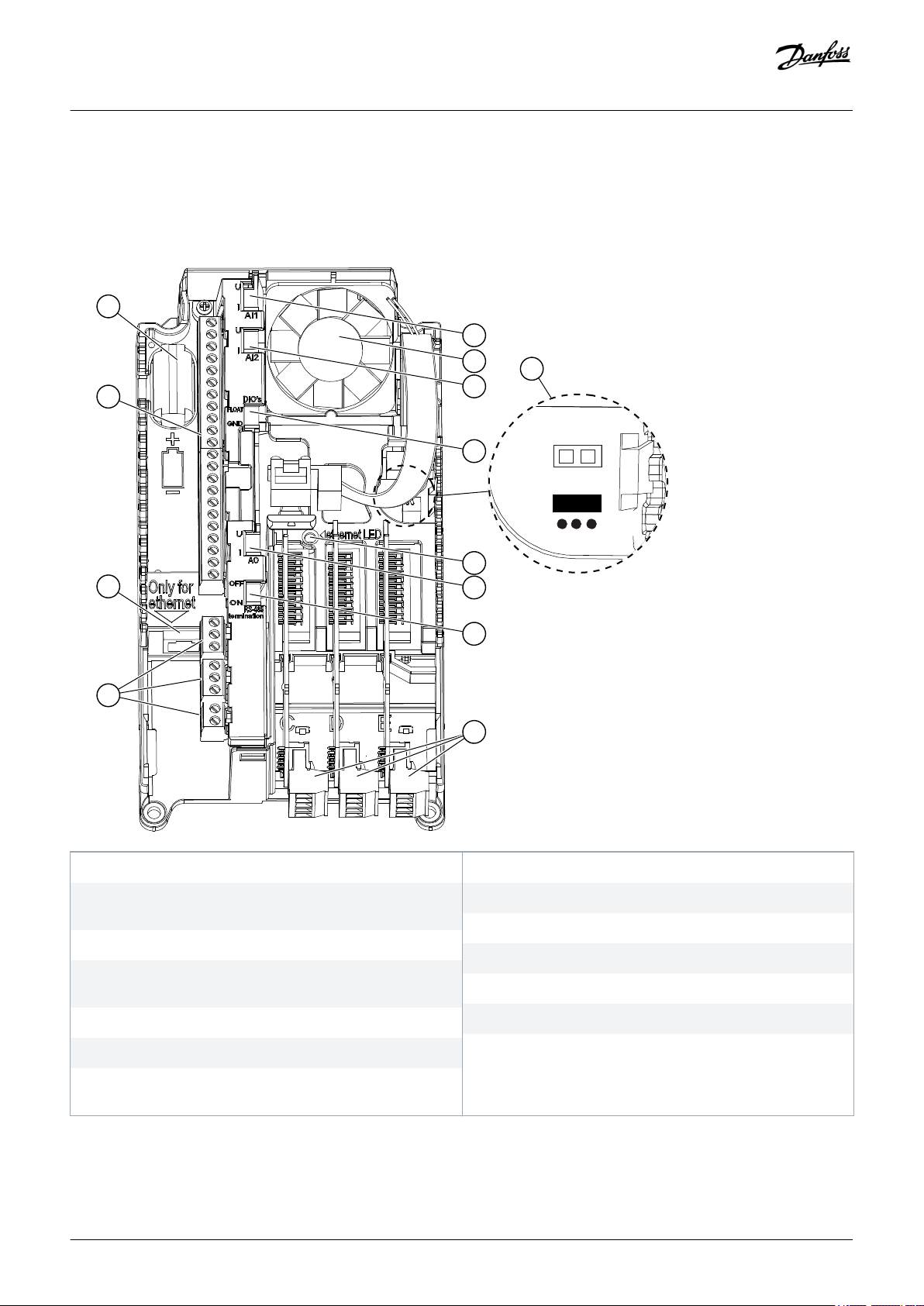
7.1 Control Unit Components
Control Unit
A The control terminals for the standard I/O connections
C The relay board terminals for 3 relay outputs or 2 relay
outputs and a thermistor
E A DIP switch for the RS485 bus termination
G A DIP switch for the isolation of the digital inputs from
ground
I A DIP switch for the signal selection of Analog Input 1
K A fan (only in IP54 of MR4 and of MR5)
M The location and the default position of the Safe Torque Off
(STO) jumper
Illustration 19: Components of the Control Unit
B The Ethernet connection
D The option boards
F A DIP switch for the signal selection of Analog Output
H A DIP switch for the signal selection of Analog Input 2
J The status indicator of the Ethernet connection
L The battery for the RTC
64 | Danfoss A/S © 2019.05
AQ298036140958en-000101 / DPD01711

Operating Guide | VACON® 100 Wall-mounted Drives
On delivery of the AC drive, the control unit contains the default control interface (graphical keypad). If special options were selected in
the order, the option boards are included loose in the delivery. On the next pages, there is information on the terminals and general
wiring examples.
It is possible to use the drive with an external power source with these properties: +24 V DC ±10%, minimum 1000 mA. Connect the
external power source to terminal 30. This voltage is sufficient to keep the control unit on and for setting the parameters. The
measurements of the main circuit (for example, the DC-link voltage, and the unit temperature) are not available when the drive is not
connected to mains.
The status indicator on the control unit shows the status of the drive. The status indicator is located in the control panel, below the
keypad, and it can show five different statuses.
Table 16: Control Unit LED Status Definitions
Color/status of the LED Status of the drive
Blinking slowly Ready
Green Run
Red Fault
Orange Alarm
Control Unit
Blinking fast Downloading software
7.2 Control Unit Cabling
7.2.1 Selection of the Control Cables
NO TI CE
CABLE SELECTION
Obey regional low-voltage standards in the cable selection.
The control cables must be a minimum of 0.5 mm2 (AWG20) multi-core shielded cables. The terminal wires must be a maximum of 2.5
mm2 (AWG13) for the relay board terminals and other terminals.
Table 17: The Tightening Torques of the Control Cables
Terminal Terminal screw size Tightening torque
(Nm)
All the terminals of the I/O board and the relay board M3 0.5 4.5
Tightening torque (lb-in)
7.2.2 Control Unit Terminals
Here is the basic description of the terminals of the default I/O and relay board. The standard I/O board has 22 fixed control terminals
and 8 relay board terminals.
Some terminals are assigned for signals that have optional functions that can be used with the DIP switches. For more information, see
7.3 DIP Switches on the Control Unit.
Danfoss A/S © 2019.05
AQ298036140958en-000101 / DPD01711| 65

e30bh417.10
RUN
FAULT
READY
*)
*)
Reference output
+10 Vref
Terminal
Standard I/O board
Signal
1
24V auxiliary voltage
24Vout6
Analog input,
voltage or current
Reference
potentiometer
1...10kΩ
Actual value
2-wire transmitter
I = (0)4...20mA
AI1+2
Analog input
common, (current)
AI1-3
Analog input,
voltage or current
AI2+4
Analog input
common, (current)
AI2-5
Analog signal
(+output)
AO1+
RUN
18
Analog output
common / I/O ground
AO1-/GND19
24V auxiliary
input voltage
+24Vin
30
24V auxiliary voltage
24Vout
12
I/O ground
GND7
I/O ground
GND13
Digital input 1
DI18
Digital input 2
DI29
Digital input 3
DI310
Digital input 4
DI414
Digital input 5
DI515
Digital input 6
DI616
Relay output 1
RO1 NC21
22
RO1 CM
RO1 NO23
Common for DI1-DI6
CM11
Common for DI1-DI6
CM
17
Serial bus, negative
RS485A
Serial bus, positive
RS485
B
Relay output 2
Relay output 3
RO2 NC24
25
RO2 CM
RO2 NO26
32
RO3 CM
RO3 NO33
Description
Frequency reference
Frequency reference
Start forward
Start reverse
External fault
DI4
DI5
Freq. ref.
Open
Closed
Open
Closed
Open
Open
Closed
Closed
Analog input 1
Preset Freq. 1
Preset Freq. 2
Preset Freq. 3
Fault reset
Output frequency
Modbus RTU
BACnet, N2
mA
Operating Guide | VACON® 100 Wall-mounted Drives
Control Unit
Illustration 20: The Signals of the Control Terminals on the Default I/O Board and the Default Control Connections
66 | Danfoss A/S © 2019.05
AQ298036140958en-000101 / DPD01711

RO1 NC
RO1 CM
RO1 NO
RO2 NC
RO2 CM
RO2 NO
RO3 CM
RO3 NO
21
22
23
24
25
26
32
33
e30bh329.10
RUN
RUN
FAULT
READY
Relay output 1
Relay output 2
Relay output 3
From Standard I/O board
Terminal Signal
Default
Relay board 1
From term. #6
or 12
From term.
#13
RO1 NC
RO1 CM
RO1 NO
RO2 NC
RO2 CM
RO2 NO
TI1+
TI1-
21
22
23
24
25
26
28
29
e30bh330.10
RUN
RUN
FAULT
NO ACTION
Relay output 1
Relay output 2
From Standard I/O board
Terminal Signal
Default
Relay board 2
From term.
#12
From term.
#13
Thermistor input
Operating Guide | VACON® 100 Wall-mounted Drives
*) You can isolate digital inputs from ground with a DIP switch. See 7.3.2 Isolation of the Digital Inputs from Ground.
There are 2 different relay boards available. If you include the optional code +SBF4 in your order, the relay output 3 is replaced with a
thermistor input.
The thermistor input function is not automatically active. To use the thermistor input function, activate the parameter Thermistor Fault
in the software. See the Application Guide.
Control Unit
Illustration 21: Standard Relay Board (+SBF3)
Illustration 22: Optional Relay Board (+SBF4)
7.3 DIP Switches on the Control Unit
7.3.1 Selection of Terminal Functions with DIP Switches
Two selections for specified terminals can be done with the DIP switches. The switches have two positions: up and down. See the
location of the DIP switches and the possible selections in illustration 23.
Danfoss A/S © 2019.05
AQ298036140958en-000101 / DPD01711| 67

A B
A
B
C
D
E
AI1
U
I
AO1
U
I
RS485
OFF
ON
AI2
U
I
e30bg737.10
Operating Guide | VACON® 100 Wall-mounted Drives
Control Unit
A The voltage signal (U), 0–10 V input
C OFF
E The RS485 bus termination
Illustration 23: The Selections of the DIP Switches
Table 18: The Default Positions of the DIP Switches
The DIP switch The default position
AI1 U
AI2 I
AO1 I
RS485 bus termination OFF
B The current signal (I), 0–20 mA input
D ON
68 | Danfoss A/S © 2019.05
AQ298036140958en-000101 / DPD01711

A
B
C
e30bg738.10
Operating Guide | VACON® 100 Wall-mounted Drives
Control Unit
7.3.2 Isolation of the Digital Inputs from Ground
It is possible to isolate from ground the digital inputs (terminals 8–10 and 14–16) on the standard I/O board. To do this, change the
position of a DIP switch on the control board.
A The digital inputs
C Connected to ground (default)
Illustration 24: Change the Position of This Switch to Isolate the Digital Inputs from Ground
B Floating
7.4 Fieldbus Connection
7.4.1 Fieldbus Terminals
The drive can be connected to fieldbus with an RS485 or an Ethernet cable.
• If an RS485 cable is used, connect it to terminals A and B of the standard I/O board.
• If an Ethernet cable is used, connect it to the Ethernet terminal.
Danfoss A/S © 2019.05
AQ298036140958en-000101 / DPD01711| 69

C
D
B
A
e30bh332.10
Operating Guide | VACON® 100 Wall-mounted Drives
Control Unit
A RS485 terminal A = Data -
C The Ethernet terminal
Illustration 25: Ethernet and RS485 Connections
B RS485 terminal B = Data +
D The control terminals
7.4.2 Internal Fieldbuses in VACON® 100 Products
VACON® 100 product family supports internally four Ethernet fieldbuses:
• Modbus TCP/UDP
• BACnet/IP
• PROFINET IO (requires +FBIE license)
• EtherNet/IP (requires +FBIE license)
Having a single Ethernet port, the Ethernet fieldbuses can be connected to networks with star topology.
The VACON® 100 family RJ45 connector does not have speed or activity LEDs. Instead it has a single LED in the middle of the AC drive.
The LED cannot be seen unless the covers are removed. The LED works as listed below:
• LED is dimmed (dark) when the port is connected to a 10 Mbit/s network.
• LED is yellow when the port is connected to a 100 Mbit/s network.
• LED is dimmed (dark) when the port is connected to a 1000 Mbit/s network. The AC drive does not support a 1000 Mbit/s Ethernet,
so there is no communication.
The VACON® 100 product family supports internally three RS485 fieldbuses:
70 | Danfoss A/S © 2019.05
AQ298036140958en-000101 / DPD01711

A
B
e30bh379.10
≥ 300 mm
90°
Operating Guide | VACON® 100 Wall-mounted Drives
• Modbus RTU
• BACnet MSTP
• Metasys N2
Control Unit
7.4.3 General Cabling Instructions for Fieldbus
To keep the response time and the number of incorrect dispatches to minimum, use only standard industrial components in the
network and avoid complex structures. The requirements for commercial cabling components are specified in section 8-8 in the
ANSI/TIA/EIA-568-B series standards. Using commercial components can decrease system performance. The use of such products or
components can cause unsatisfactory performance in industrial control applications.
7.4.3.1 Cable Routing
It is important that fieldbus cables are routed separately from motor cables. The recommended minimum distance is 300 mm. Do not
let fieldbus cables and motor cables cross each other. If it is not possible, the fieldbus cables must cross other cables at an angle of 90°.
Shielded fieldbus and control cables can be routed in parallel. To have further shielding, install a grounded metal conduit around the
fieldbus and control cable run.
A Motor cables B Fieldbus cables
Illustration 26: Routing the Motor and Fieldbus Cables
Use cables with right length. If there is extra cable, put it in a noise free location. Multiple rounds of cable and a large circumstance area
make an antenna (see illustration 27). Noise connects to fieldbus cable and can cause communication problems.
Danfoss A/S © 2019.05
AQ298036140958en-000101 / DPD01711| 71

B
A
e30bh380.10
e30bh381.10
Operating Guide | VACON® 100 Wall-mounted Drives
Control Unit
A Motor cables B Fieldbus cables
Illustration 27: Installation that Makes an Antenna
Illustration 28: Example of Good Routing of Extra Fieldbus Cable
NO TI CE
To prevent shield fracture, do not bend the cable too much or run the cable back and forth on the same path.
AQ298036140958en-000101 / DPD01711
72 | Danfoss A/S © 2019.05

Operating Guide | VACON® 100 Wall-mounted Drives
Control Unit
7.4.3.2 Strain Relief
If there is a possibility of tensile load on the cable, install it with a strain relief. When it is possible, the strain relief of the fieldbus cables
should not be done at the shield connection to ground. This may reduce the effectiveness of the bonding. The tensile load and
vibration can also damage the shield.
7.4.4 Ethernet Commissioning and Cabling
7.4.4.1 General Cabling Instructions for Ethernet
Use only shielded cables of category CAT5e or CAT6.
Table 19: The Recommended Cable Shielding
Recommendation order Cable
1 Shielded and Foiled Twisted Pair (S/FTP) CAT5e or CAT6
2 Shielded Twisted Pair (STP) CAT5e or CAT6
3 Foiled Twisted Pair (FTP) CAT5e or CAT6
4 Unshielded Twisted Pair (UTP) CAT5e or CAT6
Use standard Ethernet 100 Mbit pinout connectors. The plug type to be used is a shielded RJ45 plug, maximum length 40 mm (1.57 in).
The maximum length of the CAT5e or CAT6 cable between two RJ45 ports is 100 meters. You can get cables that have a certain length,
or get cable in bulk and assemble the connectors at commissioning. Obey the instructions of the manufacturer if you assemble the
connectors manually. If you make the cables by yourself, be sure to select correct crimp tools and use precaution. The individual
contacts of the RJ45 socket are allocated as per the T568-B standard.
In basic use, it is important that the RJ45 connectors in the cable (or the ones assembled) connect the cable shield to the ground level
of the Ethernet terminal in the AC drive.
7.4.4.2 Grounding the Cable Shield
Equipotential bonding refers to using metal parts to make ground potential everywhere in the installation the same, the system
ground. If the ground potential of all the devices is the same, you can prevent current from flowing through paths that are not
designed to have current. You can also shield cables efficiently.
An error in the equipotential bonding can cause bad quality or malfunction of the fieldbus communication. It is not easy to find an
error in equipotential bonding. It is also not easy to correct errors in large installations after commissioning. Thus, in the planning
phase it is important to plan the installation to get good equipotential bonding. In the commissioning phase, make the equipotential
bonding connections carefully.
Do grounding with low HF impedance, for example, via backplane mounting. If ground connection wires are necessary, use wires that
are as short as possible. Paint coating acts as an insulator on metal and prevents grounding. Remove paint coating before doing
grounding.
When equipotential bonding is good, the RJ45 connectors in the cable (or the ones assembled) must connect the cable shield to the
ground level of the Ethernet terminal in the AC drive. The cable shield can be connected to the ground level at both ends via the builtin RC circuit (illustration 29). This grounds the disturbances and, to some degree, prevents current from flowing in the cable shield. To
do this, use shielded Ethernet cable (S/FTP or STP) which grounds devices via a RJ45 connector and thus uses a built-in drive RC circuit.
Danfoss A/S © 2019.05
AQ298036140958en-000101 / DPD01711| 73

C D
BA
e30bh383.10
C D
BA
e30bh384.10
C D
BA
e30bh385.10
A B C
e30bh386.10
Operating Guide | VACON® 100 Wall-mounted Drives
Illustration 29: Grounding via the Built-in RC Circuit
Control Unit
When disturbances are strong, the cable shield can be exposed and then 360 degrees grounded (see
illustration 32) directly to the AC
drive ground (see illustration 31).
Illustration 30: Grounding in noisy environment with good equipotential. If potentials at points A, B, C, and D are very different and cannot be
made similar, cut the shields as in Illustration Grounding in noisy environment with poor equipotential.
If ground potentials of the connected devices are different, cable shield that is connected at both ends causes current to flow in the
shield. To prevent this, the cable shield must be disconnected or cut at some point between the devices. Grounding should be done at
a location nearest to the place where the disturbances meet the cable (see illustration 31).
Illustration 31: Grounding in Noisy Environment with Poor Equipotential. Example of Cutting Shield.
We recommend grounding the cable shield as in examples A and C (see illustration 32). Do not ground the cable shield as in example
B.
A Cable clamp
C Cable gland
Illustration 32: Grounding the Cable Shield
74 | Danfoss A/S © 2019.05
B Ground terminal
AQ298036140958en-000101 / DPD01711

Operating Guide | VACON® 100 Wall-mounted Drives
Control Unit
7.4.4.3 Using Fieldbus through an Ethernet Cable
Prerequisites:
Open the covers according to instructions in 6.4.1 Get Access and Locate the Terminals for MR4-MR7, 6.4.2 Get Access and Locate the
Terminals for MR8, or 6.4.3 Get Access and Locate the Terminals for MR9.
Danfoss A/S © 2019.05
AQ298036140958en-000101 / DPD01711| 75

A
e30bh382.10
e30bh387.10
Operating Guide | VACON® 100 Wall-mounted Drives
Ethernet Cabling
1. Connect the Ethernet cable to its terminal.
Control Unit
A The Ethernet cable
Illustration 33: Ethernet Cable Installation Location
2. In IP21, cut free the opening on the cover of the AC drive for the Ethernet cable.
3. In IP54, cut a hole in a grommet and move the cable through it.
76 | Danfoss A/S © 2019.05
AQ298036140958en-000101 / DPD01711

e30bg086.10
A
e30bh388.10
Operating Guide | VACON® 100 Wall-mounted Drives
Control Unit
A Do not cut the grommet openings wider than what is necessary for the used cables.
B If the grommet folds in when putting the cable, pull the cable back to make the grommet straight.
C Pull the first bit of the cable out of the grommet so that it stays straight. If this is not possible, make the connection tight with
some insulation tape or a cable tie.
4. Put the cover of the drive back. Pull the fieldbus cables away from other cables.
Danfoss A/S © 2019.05
A Ethernet cable
Illustration 34: Routing the Ethernet Cables in IP21
AQ298036140958en-000101 / DPD01711| 77

A
e30bh389.10
Operating Guide | VACON® 100 Wall-mounted Drives
A Ethernet cable
Illustration 35: Routing the Ethernet Cables in IP54
See more in the installation guide of the used fieldbus.
Control Unit
7.4.5 RS485 Commissioning and Cabling
7.4.5.1 General Cabling Instructions for RS485
Use only shielded cables with twisted-pair signal wires.
For example, the following cables are recommended:
• Lapp Kabel UNITRONICR BUS LD FD P A, part number 2170813 or 2170814
• Belden 9841
The plug type to be used is 2.5 mm2 (AWG13).
The theoretical maximum cable length depends on baud rate. See the following table for suggested maximum cable lengths.
Table 20: The RS485 Cable Lengths
Baud rate (kbit/s) Length of line A (m) Length of line B (m)
9.6 1200 1200
19.2 1200 1200
93.75 1200 1200
187.5 1000 600
500 400 200
1500 200 -
3000–12000 100 -
78 | Danfoss A/S © 2019.05
AQ298036140958en-000101 / DPD01711

C D
BA
e30bh384.10
C D
BA
e30bh385.10
Operating Guide | VACON® 100 Wall-mounted Drives
Control Unit
7.4.5.2 Grounding the Cable Shield
Equipotential bonding refers to using metal parts to make ground potential everywhere in the installation the same, the system
ground. If the ground potential of all the devices is the same, you can prevent current from flowing through paths that are not
designed to have current. You can also shield cables efficiently.
An error in the equipotential bonding can cause bad quality or malfunction of the fieldbus communication. It is not easy to find an
error in equipotential bonding. It is also not easy to correct errors in large installations after commissioning. Thus, in the planning
phase it is important to plan the installation to get good equipotential bonding. In the commissioning phase, make the equipotential
bonding connections carefully.
Do grounding with low HF impedance, for example, via backplane mounting. If ground connection wires are necessary, use wires that
are as short as possible. Note that paint coating acts as an insulator on metal and prevents grounding. Remove paint coating before
doing grounding.
This chapter describes the principles of cable shield grounding. Notice that the internal RS485 fieldbus in VACON 100® products does
not have jumpers for grounding options.
Connect the cable shield directly to the frame of the AC drive (see illustration 36 and illustration 38).
Illustration 36: Grounding in noisy environment with good equipotential. If potentials at points A, B, C and D are very different and cannot be
made similar, cut the shields as in Illustration Grounding in noisy environment with poor equipotential.
If ground potentials of the connected devices are different, cable shield that is connected at both ends causes current to flow in the
shield. To prevent this, the cable shield must be disconnected or cut at some point between the devices (see illustration 37).
When disturbances are strong, the cable shield can be exposed and then 360 degrees grounded directly to the AC drive ground (see
illustration 38). When the connection is made like in illustration 37, grounding should be done at a location nearest to the place where
the disturbances meet the cable.
Illustration 37: Grounding in Noisy Environment with Poor Equipotential. An Example of Cutting the Shield.
We recommend grounding the cable shield as in examples A and C (see illustration 38). Do not ground the cable shield as in example
B.
Danfoss A/S © 2019.05
AQ298036140958en-000101 / DPD01711| 79

A B C
e30bh386.10
Operating Guide | VACON® 100 Wall-mounted Drives
Control Unit
A Cable clamp
C Cable gland
Illustration 38: Grounding the Cable Shield
B Ground terminal
7.4.5.3 The RS485 Bus Biasing
When no device on the RS485 bus line transmits data, all devices are in an idle state. In such conditions, the bus voltage is in an
indefinite state, usually near 0 V, because of the termination resistors. This can cause problems in character reception because the
RS485 standard considers the voltage interval from -200 m to +200 mV as an undefined state. Thus, bus biasing is necessary to keep
the voltage in state ‘1’ (above +200 mV) also between the messages.
Unless the first and last device in the RS485 bus line have a built-in bus biasing function, you must add a separate active termination
resistor specially designed for the RS485 bus (e.g. Siemens active RS485 terminating element 6ES7972-0DA00-0AA0).
7.4.5.4 Using Fieldbus through an RS485 Cable
Prerequisites:
Open the covers according to instructions in 6.4.1 Get Access and Locate the Terminals for MR4-MR7, 6.4.2 Get Access and Locate the
Terminals for MR8, or 6.4.3 Get Access and Locate the Terminals for MR9.
80 | Danfoss A/S © 2019.05
AQ298036140958en-000101 / DPD01711

10
5
e30bg841.10
15 mm
e30bg842.10
e30bg843.10
Operating Guide | VACON® 100 Wall-mounted Drives
Control Unit
RS485 Cabling
1. Remove approximately 15 mm (0.59 in) of the gray shield of the RS485 cable. Do this for the two fieldbus cables.
A Strip the cables for approximately 5 mm (0.20 in) to put them in the terminals. Do not keep more than 10 mm (0.39 in) of the
cable outside the terminals.
B Strip the cable at such a distance from the terminal that it can be attached to the frame with the grounding clamp for the
control cable. Strip the cable at a maximum length of 15 mm (0.59 in). Do not remove the aluminum shield of the cable.
2. Connect the cable to the default I/O board of the drive, in terminals A and B.
• A = negative
• B = positive
3. Attach the shield of the cable to the frame of the drive with a grounding clamp for the control cable to make a grounding
connection.
Danfoss A/S © 2019.05
AQ298036140958en-000101 / DPD01711| 81

e30bh333.10
e30bg845.10
Operating Guide | VACON® 100 Wall-mounted Drives
Illustration 39: Grounding the Cable with a Grounding Clamp
Control Unit
4. If the drive is the last device on the fieldbus line, set the bus termination. Set the bus termination for the first and the last device of
the fieldbus line. It is recommended that the first device on the fieldbus is the master device.
A Find the DIP switches on the left side of the control unit of the drive.
B Set the DIP switch of the RS485 bus termination to the ON position.
The termination resistors are placed at both ends of the fieldbus line to decrease signal reflections on the line.
Biasing is built in the bus termination resistor. The termination resistance is 220 Ω.
82 | Danfoss A/S © 2019.05
AQ298036140958en-000101 / DPD01711

D
D
E
A
C
B
e30bg846.10
e30bh336.10
Operating Guide | VACON® 100 Wall-mounted Drives
Control Unit
A The termination is activated
C The termination is activated with a DIP switch
E The fieldbus
Illustration 40: Setting the Bus Termination for a Fieldbus Line
B The termination is deactivated
D The bus termination. The resistance is 220 Ω.
NO TI CE
LOSS OF TERMINATION RESISTANCE
If the last device on the fieldbus line is powered down, the termination resistance is lost. The loss of termination resistance
causes signal reflections on the line, which can disrupt the fieldbus communication.
- Do not power down the last device on the fieldbus line while the fieldbus is active.
5. In IP21, unless you have cut the openings for other cables, cut an opening on the cover of the drive for the RS485 cable.
6. Put the cover of the drive back. Pull the RS485 cables to the side.
A Keep the distance of the Ethernet, I/O and Fieldbus cables from the motor cable at a minimum of 30 cm (11.81 in).
Danfoss A/S © 2019.05
AQ298036140958en-000101 / DPD01711| 83

A
e30bh337.10
Operating Guide | VACON® 100 Wall-mounted Drives
B Move the fieldbus cables away from the motor cable.
Control Unit
A The fieldbus cables
Illustration 41: Routing the Fieldbus Cables
7.5 Available Option Boards
Table 21: Option Boards and their Correct Option Board Slots
The option board The name of the option board The correct slot or slots
OPTB1 The I/O expander board C, D, E
OPTB2 The Thermistor relay board C, D, E
OPTB4 The I/O expander board C, D, E
OPTB5 The Relay board C, D, E
OPTB9 The I/O expander board C, D, E
OPTBF The I/O expander board C, D, E
OPTBH The Temperature measurement board C, D, E
OPTBJ The Safe Torque Off board E
OPTC4 The LonWorks fieldbus board D, E
OPTE2 The RS485 (Modbus/N2) fieldbus board D, E
84 | Danfoss A/S © 2019.05
AQ298036140958en-000101 / DPD01711

Operating Guide | VACON® 100 Wall-mounted Drives
The option board The name of the option board The correct slot or slots
OPTE3 The PROFIBUS DPV1 fieldbus board D, E
OPTE5 The PROFIBUS DPV1 fieldbus board (with a type D connector) D, E
OPTE6 The CANopen fieldbus board D, E
OPTE7 The DeviceNet fieldbus board D, E
OPTE8 The RS485 (Modbus/N2) fieldbus board (with a type D connector) D, E
OPTE9 The Dual-port ethernet fieldbus board D, E
OPTEA The Advanced dual-port ethernet fieldbus board D, E
OPTEC The EtherCAT fieldbus board D, E
Control Unit
7.6 Option Board Installation
Prerequisites:
WA RN IN G
SHOCK HAZARD FROM CONTROL TERMINALS
The control terminals can have a dangerous voltage also when the drive is disconnected from mains. A contact with this
voltage can lead to injury.
Make sure that there is no voltage in the control terminals before touching the control terminals.
-
CA UT IO N
DAMAGE TO OPTION BOARDS
Do not install, remove, or replace option boards on the drive when the power is on. Doing this can cause damage to the boards.
Switch off the AC drive before installing, removing, or replacing option boards on the drive.
-
NO TI CE
INCOMPATIBLE OPTION BOARDS
It is not possible to install option boards that are not compatible with the drive.
If the installed board is an OPTB or an OPTC option board, make sure that the label on it says "dv" (dual voltage). This marking shows
that the option board is compatible with the drive.
Danfoss A/S © 2019.05
AQ298036140958en-000101 / DPD01711| 85

OPT
dv
A
e30bg847.10
e30bg848.10
B
A
e30bg849.10
Operating Guide | VACON® 100 Wall-mounted Drives
A The slot coding
Illustration 42: Label on the Option Board
Installation Procedure
1. To get access to the option slots, open the cover of the control unit.
Control Unit
2. Install the option board into the correct slot: C, D, or E.
The option board has a slot coding, because of which it is not possible to install the option board in an incorrect slot.
A The slot coding B The option slots
Illustration 43: Installing the Option Boards
3. Close the cover of the control unit.
86 | Danfoss A/S © 2019.05
AQ298036140958en-000101 / DPD01711

Operating Guide | VACON® 100 Wall-mounted Drives
Control Unit
7.7 Battery for the Real-Time Clock (RTC)
To use the real-time clock (RTC), a battery must be installed in the left side of the control unit. See 7.1 Control Unit Components. Use a
½ AA battery with 3.6 V and a capacity of 1000–1200 mAh. Use, for example, a Vitzrocell SB-AA02 battery.
The battery lasts approximately 10 years. See more about the functions of the RTC in the application guides.
7.8 Galvanic Isolation Barriers
The control connections are isolated from the mains. The ground terminals are permanently connected to the I/O ground.
The digital inputs on the standard I/O board can be galvanically isolated from the I/O ground. To isolate the digital inputs, use the DIP
switch that has the positions FLOAT and GND. See 7.3.2 Isolation of the Digital Inputs from Ground.
Danfoss A/S © 2019.05
AQ298036140958en-000101 / DPD01711| 87

A
B
e30bh340.10
10Vref
GND
+24V
GND
AI1+
AI1-
AI2+
AI2DI1...
DI6
CM
AO1+
AO1+24Vin
RS485
RO1/1
RO1/2
RO1/3
RO2/1
RO2/2
RO2/3
TI1+
TI1-
L1
L2
L3
DC- DC+/R+ R-
U
V
W
Operating Guide | VACON® 100 Wall-mounted Drives
Control Unit
A The control unit B The power unit
Illustration 44: Galvanic isolation barriers
7.9 Description of the Control Panel
7.9.1 Control Panel and the Keypad
The control panel is the interface between the AC drive and the user. With the control panel, you can control the speed of a motor and
monitor the status of the AC drive. You can also set the parameters of the AC drive.
88 | Danfoss A/S © 2019.05
AQ298036140958en-000101 / DPD01711

e30bu012
A
B C
I
H D
G
F E
Operating Guide | VACON® 100 Wall-mounted Drives
Control Unit
A The [BACK/RESET] button. Use it to move back in the menu,
exit the Edit mode, reset a fault.
C The [FUNCT] button. Use it to change the rotation direction
of the motor, access the control page, and change the
control place.
E The START button.
G The STOP button.
I The [OK] button. Use it to go into an active level or item, or to
accept a selection.
Illustration 45: Buttons of the VACON® 100 Keypad
B The arrow button UP. Use it to scroll the menu up and to
increase a value.
D The arrow button RIGHT.
F The arrow button DOWN. Use it to scroll the menu down and
to decrease a value.
H The arrow button LEFT. Use it to move the cursor left.
7.9.2 Displays of the Control Panel
There are 2 display types: the graphical display and the text display. The control panel always has the same keypad and buttons.
The display shows this data.
• The status of the motor and the drive.
• Faults in the motor and in the drive.
• Your location in the menu structure.
If the text in the text display is too long for the display, the text scrolls to show the full text string. Some functions are only available in
the graphical display.
Danfoss A/S © 2019.05
AQ298036140958en-000101 / DPD01711| 89

STOP
READY
I/O
Main Menu
A
B C D E
F
H
G
Quick Setup
( 17 )
Monitor
( 5 )
Parameters
( 12 )
M1ID:
e30bu013.10
A B
F
C
D
E
e30bu014.10
Operating Guide | VACON® 100 Wall-mounted Drives
Control Unit
A The first status field: STOP/RUN
C The second status field: READY/NOT READY/FAULT
E The control place field: PC/I/O/KEYPAD/ FIELDBUS
G An activated group or item
Illustration 46: Graphical Display of the Control Panel
B The rotation direction of the motor
D The alarm field: ALARM/-
F The location field: the ID number of the parameter and the
current location in the menu
H The number of items in the group in question
A The indicators of status
C The name of the group or item of the current location
E The indicators of the control place
Illustration 47: Text Display of the Control Panel
See more information in the VACON® 100 INDUSTRIAL, VACON® 100 FLOW, and VACON® 100 HVAC Application Guides.
90 | Danfoss A/S © 2019.05
B The indicators of alarm and fault
D The current location in the menu
F The indicators of the rotation direction
AQ298036140958en-000101 / DPD01711

Operating Guide | VACON® 100 Wall-mounted Drives
Commissioning
8 Commissioning
8.1 Safety Checks before Starting the Commissioning
Before starting the commissioning, read these warnings.
DA NG ER
SHOCK HAZARD FROM POWER UNIT COMPONENTS
The power unit components are live when the drive is connected to mains. A contact with this voltage can lead to death or
serious injury.
Do not touch the components of the power unit when the drive is connected to mains. Before connecting the drive to
-
mains, make sure that the covers of the drive are closed.
DA NG ER
SHOCK HAZARD FROM TERMINALS
The motor terminals U, V, W, the brake resistor terminals, or the DC terminals are live when the drive is connected to mains, also
when the motor does not operate. A contact with this voltage can lead to death or serious injury.
Do not touch the motor terminals U, V, W, the brake resistor terminals, or the DC terminals when the drive is connected to
-
mains. Before connecting the drive to mains, make sure that the covers of the drive are closed.
DA NG ER
SHOCK HAZARD FROM DC LINK OR EXTERNAL SOURCE
The terminal connections and the components of the drive can be live 5 minutes after the drive is disconnected from the mains
and the motor has stopped. Also the load side of the drive can generate voltage. A contact with this voltage can lead to death
or serious injury.
Before doing electrical work on the drive:
-
• Disconnect the drive from the mains and make sure that the motor has stopped.
• Lock out and tag out the power source to the drive.
• Make sure that no external source generates unintended voltage during work.
• Wait 5 minutes before opening the cabinet door or the cover of the AC drive.
• Use a measuring device to make sure that there is no voltage.
WA RN IN G
SHOCK HAZARD FROM CONTROL TERMINALS
The control terminals can have a dangerous voltage also when the drive is disconnected from mains. A contact with this
voltage can lead to injury.
Make sure that there is no voltage in the control terminals before touching the control terminals.
-
Danfoss A/S © 2019.05
AQ298036140958en-000101 / DPD01711| 91

Operating Guide | VACON® 100 Wall-mounted Drives
Commissioning
8.2 Commissioning the AC Drive
Context:
Follow these instructions to commission the AC drive.
Prerequisites:
Read the safety instructions in 2.2 Danger and Warnings and 8.1 Safety Checks before Starting the Commissioning and obey them.
Procedure
1. Make sure that the motor is installed correctly.
2. Make sure that the motor is not connected to mains.
3. Make sure that the AC drive and the motor are grounded.
4. Make sure to select the mains cable, the brake cable, and the motor cable correctly.
For information on cable selections, see:
• 6.1.3 Cable Selection and Dimensioning and related tables
• 6.1 Cable Connections
• 6.2 EMC-compliant Installation
5. Make sure that the control cables are as far as possible from the power cables. See 6.5.1 Additional Instructions for Cable
Installation.
6. Make sure that the shields of the shielded cables are connected to a grounding terminal that is identified with the PE symbol.
7. Check the tightening torques of all the terminals.
8. Make sure that no power correction capacitors are connected to the motor cable.
9. Make sure that the cables do not touch the electrical components of the drive.
10. Make sure that the common inputs of the digital input groups are connected to +24 V or ground of the control terminal or the
external power source.
11. Check the quality and quantity of the cooling air.
For further information on cooling requirements, see:
• 5.3.1 General Cooling Requirements
• 5.3.2 Cooling
• 5.3.3 Necessary Quantity of Cooling Air
12. Make sure that there is no condensation on the surfaces of the AC drive.
13. Make sure that there are no unwanted objects in the installation space.
14. Before connecting the drive to mains, check the installation and the condition of all the fuses (see 10.3.1 List of Cable and Fuse Size
Information) and other protective devices.
8.3 Measuring the Cable and Motor Insulation
Do these checks if necessary.
• The insulation checks of the motor cable, see 8.3.1 Insulation Checks of the Motor Cable
• The insulation checks of the mains cable, see 8.3.2 Insulation Checks of the Mains Cable
• The insulation checks of the motor, see 8.3.3 Insulation Checks of the Motor
92 | Danfoss A/S © 2019.05
AQ298036140958en-000101 / DPD01711

Operating Guide | VACON® 100 Wall-mounted Drives
Commissioning
8.3.1 Insulation Checks of the Motor Cable
Context:
Use these instructions to check the insulation of the motor cable.
Procedure
1. Disconnect the motor cable from the terminals U, V, and W and from the motor.
2. Measure the insulation resistance of the motor cable between phase conductors 1 and 2, between phase conductors 1 and 3, and
between phase conductors 2 and 3.
3. Measure the insulation resistance between each phase conductor and the grounding conductor.
4. The insulation resistance must be >1 MΩ at the ambient temperature of 20 °C (68 °F).
8.3.2 Insulation Checks of the Mains Cable
Context:
Use these instructions to check the insulation of the mains cable.
Procedure
1. Disconnect the mains cable from the terminals L1, L2, and L3 and from mains.
2. Measure the insulation resistance of the mains cable between phase conductors 1 and 2, between phase conductors 1 and 3, and
between phase conductors 2 and 3.
3. Measure the insulation resistance between each phase conductor and the grounding conductor.
4. The insulation resistance must be >1 MΩ at the ambient temperature of 20 °C (68 °F).
8.3.3 Insulation Checks of the Motor
Context:
Use these instructions to check the insulation of the motor.
NO TI CE
Obey the instructions of the motor manufacturer.
Procedure
1. Disconnect the motor cable from the motor.
2. Open the bridging connections in the motor connection box.
3. Measure the insulation resistance of each motor winding. The voltage must be the same or higher than the motor nominal voltage,
but at least 1000 V.
4. The insulation resistance must be >1 MΩ at the ambient temperature of 20 °C (68 °F).
5. Connect the motor cables to the motor.
6. Do the final insulation check on the drive side. Put all phases together and measure to the ground.
7. Connect the motor cables to the drive.
Danfoss A/S © 2019.05
AQ298036140958en-000101 / DPD01711| 93

Operating Guide | VACON® 100 Wall-mounted Drives
Commissioning
8.4 Checking the AC Drive after Commissioning
Context:
Before starting the motor, do these checks.
Procedure
1. Make sure that all the START and STOP switches that are connected to the control terminals are in the STOP position.
2. Make sure that the motor can be started safely.
3. Activate the Start-up wizard. See the relevant application guide.
4. Set the maximum frequency reference (that is, the maximum speed of the motor) to agree with the motor and the device that is
connected to the motor.
94 | Danfoss A/S © 2019.05
AQ298036140958en-000101 / DPD01711

Operating Guide | VACON® 100 Wall-mounted Drives
Maintenance
9 Maintenance
9.1 Maintenance Schedule
To make sure that the drive operates correctly and has a long life, we recommend doing regular maintenance. Refer to the table for
maintenance intervals.
It is not necessary to replace the main capacitors of the drive, because they are thin film type capacitors.
Table 22: Maintenance Intervals and Tasks
Maintenance interval Maintenance task
Regularly Check the tightening torques of the terminals.
Check the filters.
6–24 months (The interval is different in different environments.)
24 months (The interval is different in different environments.)
3–6 years In IP54, change the internal fan.
6–10 years Change the main fan.
10 years Replace the battery of the RTC.
Check the mains terminals, the motor terminals, and the control terminals.
Make sure that the cooling fan operates correctly.
Make sure that there is no corrosion on the terminals, the busbars, or other surfaces.
Check the door filters, if you have a cabinet installation.
Clean the heat sink and the cooling channel.
Danfoss A/S © 2019.05
AQ298036140958en-000101 / DPD01711| 95

Ø25 (0.98)
Ø25 (0.98)
Ø7 (0.28)
Ø13
(0.51)
e30bh139.10
IP21
IP54
112 (4.41)
147 (5.79)
128 (5.04)
100 (3.94)
313 (12.32)
100 (3.94)
328 (12.91)
190 (7.48)
151 (5.94)
112 (4.41)
Operating Guide | VACON® 100 Wall-mounted Drives
10 Specifications
10.1 Weight of the Drive
Table 23: Weight of the Drive
Enclosure size Weight [kg] Weight [lb.]
MR4 6.0 13.2
MR5 10.0 20.0
MR6 20.0 44.1
MR7 37.5 82.7
MR8 66.0 145.5
MR9 119.5 263.5
10.2 Dimensions
10.2.1 Dimensions for Wall-mounting
Specifications
10.2.1.1 Dimensions for Wall-mounting for MR4
Illustration 48: Dimensions of the AC Drive, MR4, mm (in)
96 | Danfoss A/S © 2019.05
AQ298036140958en-000101 / DPD01711

Ø7 (0.28)
Ø33
(1.30)
Ø25
(0.98)
Ø25 (0.98)
Ø33
(1.30)
A
A
e30bh140.10
214 (8.43)
144 (5.67)
115 (4.53)
Ø7
0.28
Ø14
0.55
Ø7 (0.28)
100 (3.94)
419 (16.50)
406 (15.98)
115 (4.53)
100 (3.94)
IP21
39 (1.54)
37.5 (1.48)
130 (5.12)
134 (5.28)
130 (5.12)
134 (5.28)
IP54
Operating Guide | VACON® 100 Wall-mounted Drives
10.2.1.2 Dimensions for Wall-mounting for MR5
Specifications
A
Mounting holes for replacing a VACON® NX AC drive with a VACON® 100 Wall-mounted AC drive
Illustration 49: Dimensions of the AC Drive, MR5, mm (in)
Danfoss A/S © 2019.05
AQ298036140958en-000101 / DPD01711| 97

e30bh141.10
195 (7.68)
148 (5.83)
Ø15.5 (0.61)
Ø9 (0.35)
557 (21.93)
541 (21.30)
Ø9 (0.35)
148 (5.83)
229 (9.02)
148 (5.83)
151 (5.94)
IP21
IP54
42 (1.65) 43.7 (1.72)
148 (5.83)
151 (5.94)
Ø40
1.57
Ø33
1.30
Ø40
1.57
Ø25 (0.98)
Operating Guide | VACON® 100 Wall-mounted Drives
10.2.1.3 Dimensions for Wall-mounting for MR6
Specifications
Illustration 50: Dimensions of the AC Drive, MR6, mm (in)
98 | Danfoss A/S © 2019.05
AQ298036140958en-000101 / DPD01711

e30bh142.10
259 (10.20)
Ø20 (0.79)
660 (25.98)
645 (25.39)
237 (9.33)
190 (7.48)
IP21
IP54
160 (6.30)
211 (8.31)
160 (6.30)
217 (8.54)
Ø9 (0.35)
Ø16 (0.63)
Ø51 (2.01)
Ø25 (0.98)
Ø50 (1.97)
Operating Guide | VACON® 100 Wall-mounted Drives
10.2.1.4 Dimensions for Wall-mounting for MR7
Specifications
Illustration 51: Dimensions of the AC Drive, MR7, mm (in)
Danfoss A/S © 2019.05
AQ298036140958en-000101 / DPD01711| 99

e30bh143.10
Ø25 (0.98)
Ø60 (2.36)
Ø11 (0.43)
Ø22 (0.87)
Ø9 (0.35)
Ø9 (0.35)
164 (6.46)
62.5 (2.46)
114 (4.49)
3 x 38 (3 x 1.50)
117 (4.61) 188 (7.40)
9 (0.35)
663 (26.10)
22 (0.87)
262 (10.31)
217 (8.54)
235 (9.25)
216 (8.50)
290 (11.42)
966 (38.03)
343 (13.50)
Operating Guide | VACON® 100 Wall-mounted Drives
10.2.1.5 Dimensions for Wall-mounting for MR8
Specifications
Illustration 52: Dimensions of the AC Drive, MR8, mm (in)
100 | Danfoss A/S © 2019.05
AQ298036140958en-000101 / DPD01711
 Loading...