

Page 1

vacon 100 industrial
®
vacon 100 flow
®
®
vacon 100 hvac
ac drives
drive supply switch
installation instruction
taajuusmuuttajan syöttökytkin
asennusohje
netztrennschalter
installationsanleitung
Interrupteur d'alimentation du
convertisseur de fréquence
manuel d’installation
lastbrytare
installationsinstruktion
hoofdschakelaar frequentieregelaar
installatiehandleiding
Page 2

Page 3

vacon • 3
TABLE OF CONTENTS
Document ID: DPD01421D
Revision release date: 19.03.2018
UK: VACON® 100 drive supply switch.............................................................................. 4
1. General .................................................................................................................................. 4
2. Installation............................................................................................................................. 5
3. Cable requirements .............................................................................................................. 9
4. Mechanical dimensions....................................................................................................... 10
FI: VACON® 100 -taajuusmuuttajan syöttökytkin .......................................................... 11
1. Yleistä .................................................................................................................................. 11
2. Asennus............................................................................................................................... 12
3. Kaapelivaatimukset............................................................................................................. 16
4. Mekaaniset mitat................................................................................................................. 17
DE: VACON® 100 Netztrennschalter.............................................................................. 18
1. Allgemeines......................................................................................................................... 18
2. Installation........................................................................................................................... 19
3. Kabelanforderungen ........................................................................................................... 23
4. Mechanische Abmessungen ............................................................................................... 24
FR : Interrupteur d'alimentation du convertisseur de fréquence VACON® 100............. 25
1. Général ................................................................................................................................ 25
2. Installation........................................................................................................................... 26
3. Caractéristiques des câbles................................................................................................ 30
4. Dimensions mécaniques..................................................................................................... 31
SE: VACON® 100 lastbrytare ......................................................................................... 32
1. Allmänt ................................................................................................................................ 32
2. Installation........................................................................................................................... 33
3. Krav på kablar ..................................................................................................................... 37
4. Mekaniska mått................................................................................................................... 38
NL: Hoofdschakelaar VACON® 100 frequentieregelaar ................................................ 39
1. Algemeen............................................................................................................................. 39
2. Installatie............................................................................................................................. 40
3. Kabelvereisten .................................................................................................................... 44
4. Fysieke afmetingen ............................................................................................................. 45
Local contacts: http://drives.danfoss.com/danfoss-drives/local-contacts/
Page 4
vacon • 4 UK: VACON® 100 drive supply switch
13006.emf
UK: VACON® 100 DRIVE SUPPLY SWITCH
1. General
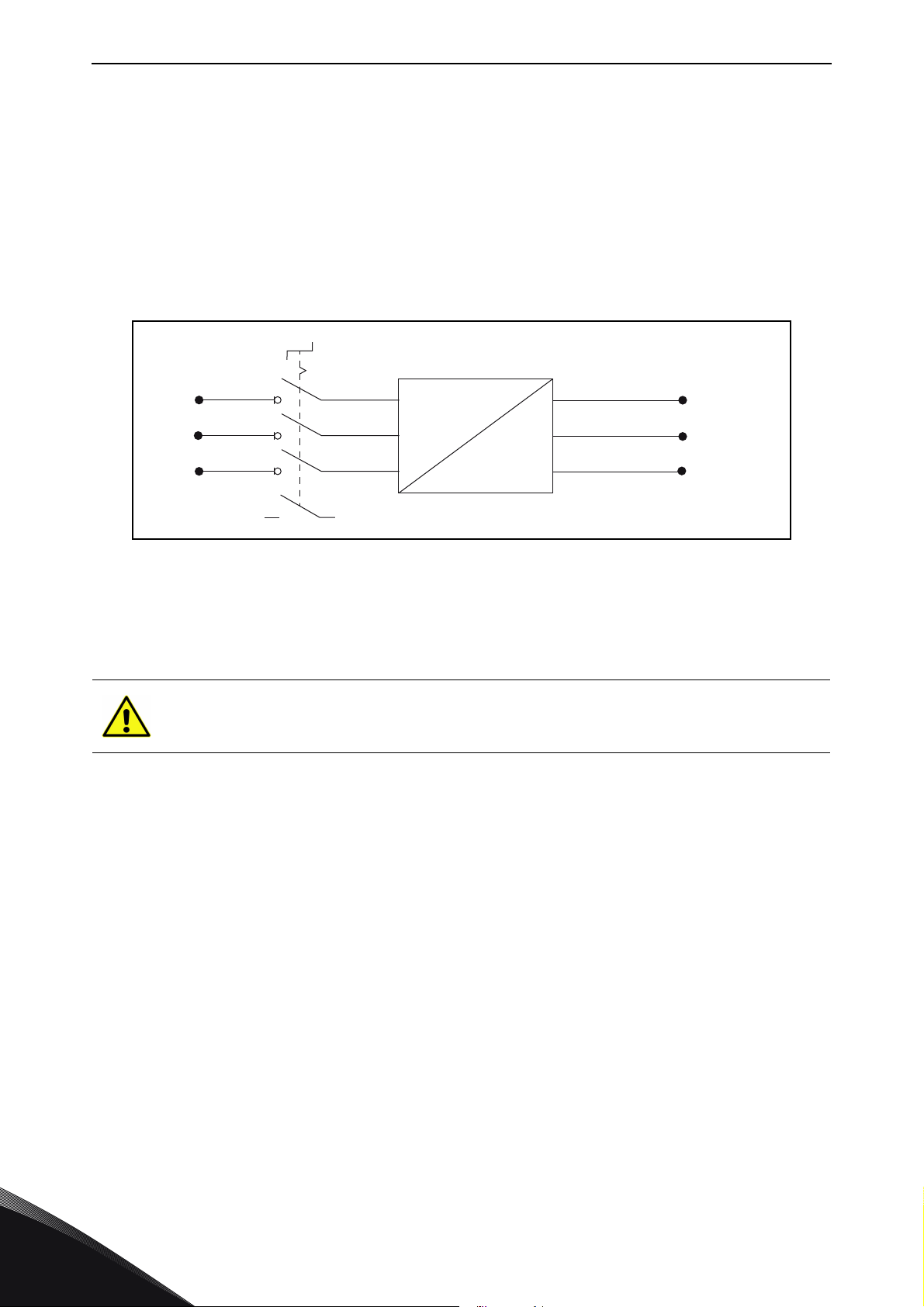
The drive supply switch is used for switching off the input power of the drive. This option is available
for drive sizes MR4-MR7 with IP54 enclosure class up to output current 105A, see the exact data in
Table 1. The drive supply switch has CE approval up to 105A and is UL listed up to 87A.
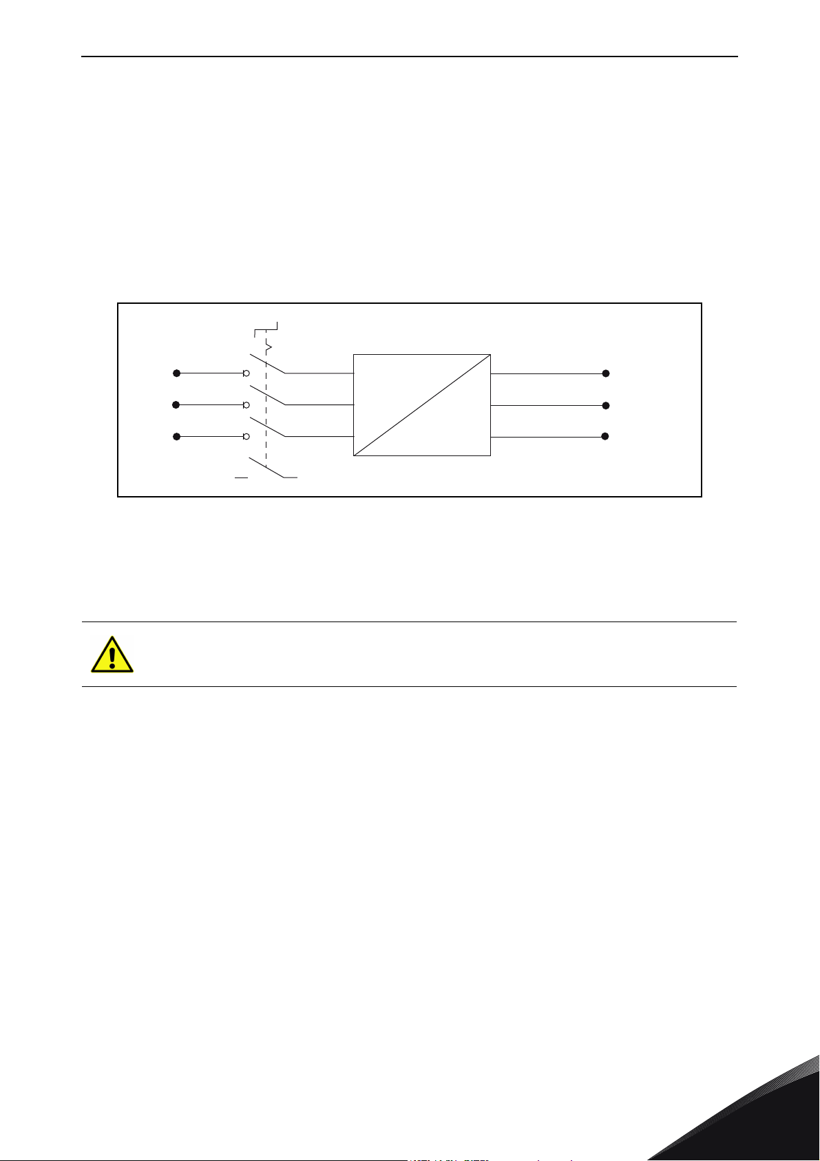
Drive supply switch operation principle:
L1
1
f
L2
L3
One additional auxiliary switch, type normal open (NO), is added on the drive supply switch as
standard. This contact switch helps in receiving status information of the drive supply switch
for PLC, etc.
CAUTION!
The drive supply switch is a safety device. It is not allowed to use the drive supply
switch when the drive is in operation.
Chapter 2 presents the installation steps, the maximum cable sizes and tightening torques are
given in Chapter 3 and the mechanical dimensions of drives with the drive supply switch option
are given in Chapter 4.
2
f
U/T1
V/T2
W/T3
uk
NOTE! When using Profibus option board OPT-E5 in MR4 with a drive supply switch, it's recommended
to use a Phoenix Profibus connector (SUBCON-PLUS-PROFIB/AX/SC 27 44 38 0) to ensure mechanical
compatibility.
Local contacts: http://drives.danfoss.com/danfoss-drives/local-contacts/
Page 5
UK: VACON® 100 drive supply switch vacon • 5
M
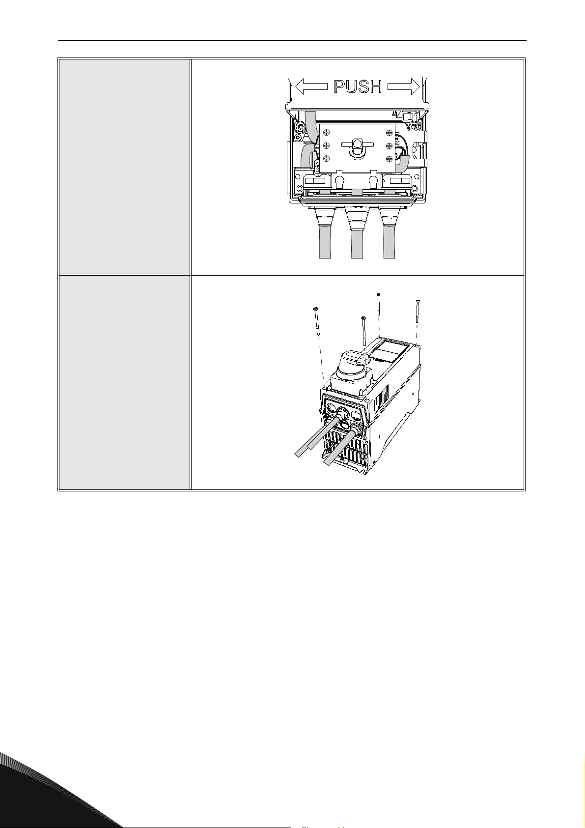
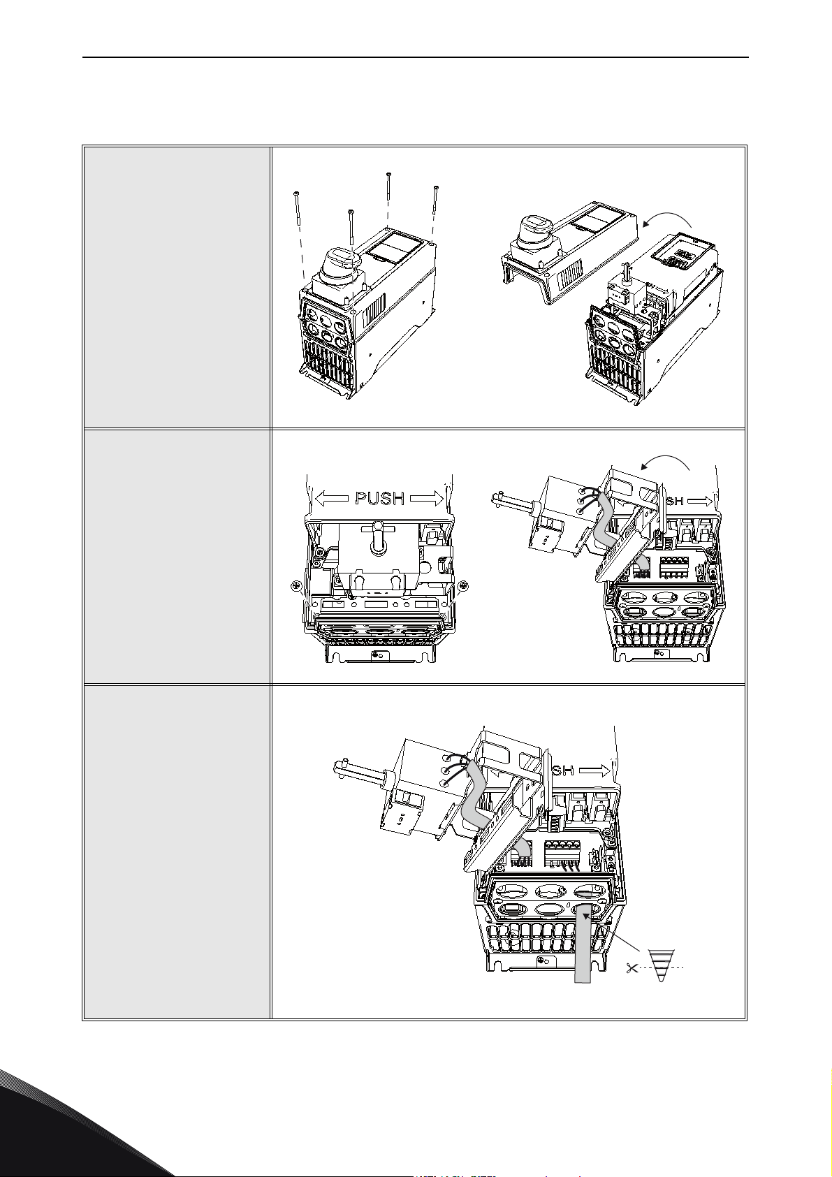
2. Installation
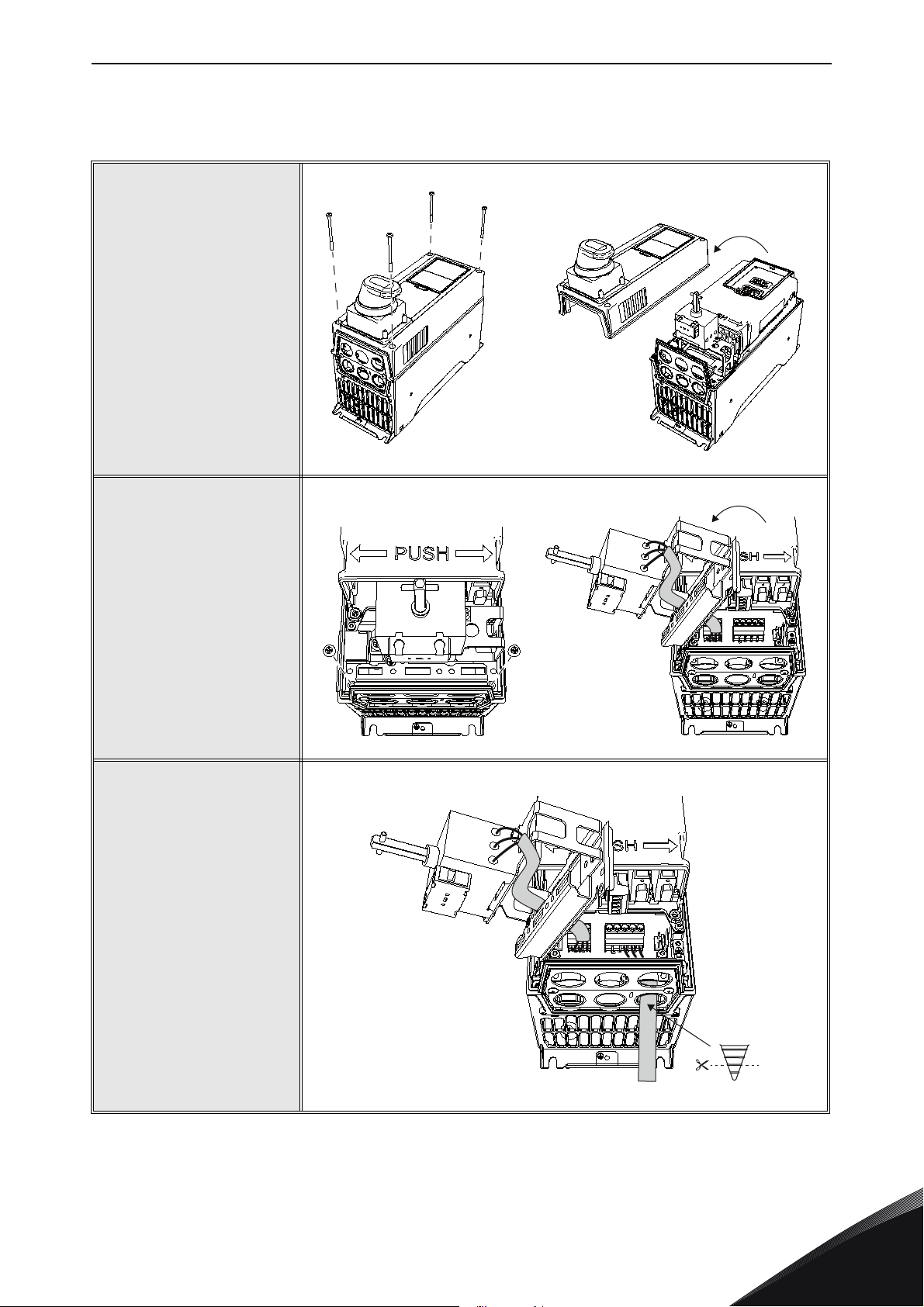
1
Remove the cover of
the drive.
2
Remove the two screws of
the drive supply switch
and tilt the switch to
the left.
3
Connect the motor
cable “M” (see Step 4).
Tighten the screws
according to the tightening torques given in
Table 1. Check also the
tightening of the factoryinstalled drive supply
switch cable!
NOTE! Remember to use
cable grommets provided
with the drive, see the
VACON
manual for detailed cable
installation instructions!
®
100 installation
Local contacts: http://drives.danfoss.com/danfoss-drives/local-contacts/
uk
Page 6
vacon • 6 UK: VACON® 100 drive supply switch
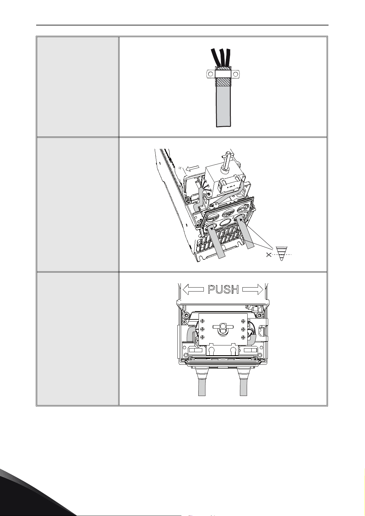
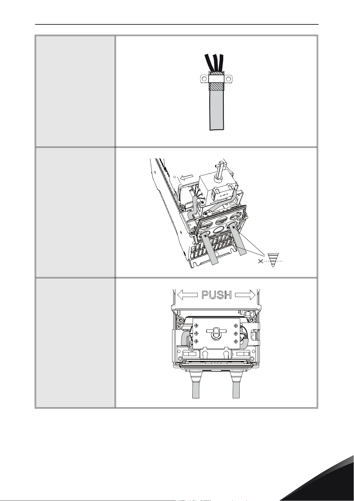
4
Attaching the cables: fold
the cable shield backwards onto the cable and
attach the cable with
a cable clamp on the
shield.
NOTE! See detailed cable
installation instructions in
®
the VACON
100
installation manual!
5
Install the supply cable
“S” and lead it to the drive
supply switch as shown in
the picture.
NOTE 1! Protect the
cables as close to the
drive supply switch as
possible with an insulation
tube.
NOTE 2! See detailed
cable installation
instructions in the
VACON
®
100 installation
manual!
S
M
uk
6
The motor and supply
cable installation seen
from above.
2T1
4T2
6T3
S
Local contacts: http://drives.danfoss.com/danfoss-drives/local-contacts/
1L1
3L2
5L3
M
Page 7
UK: VACON® 100 drive supply switch vacon • 7
S
M
2T1
4T2
6T3
1L1
3L2
5L3
M
S
D
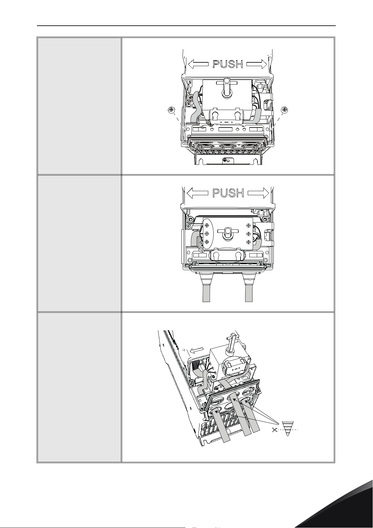
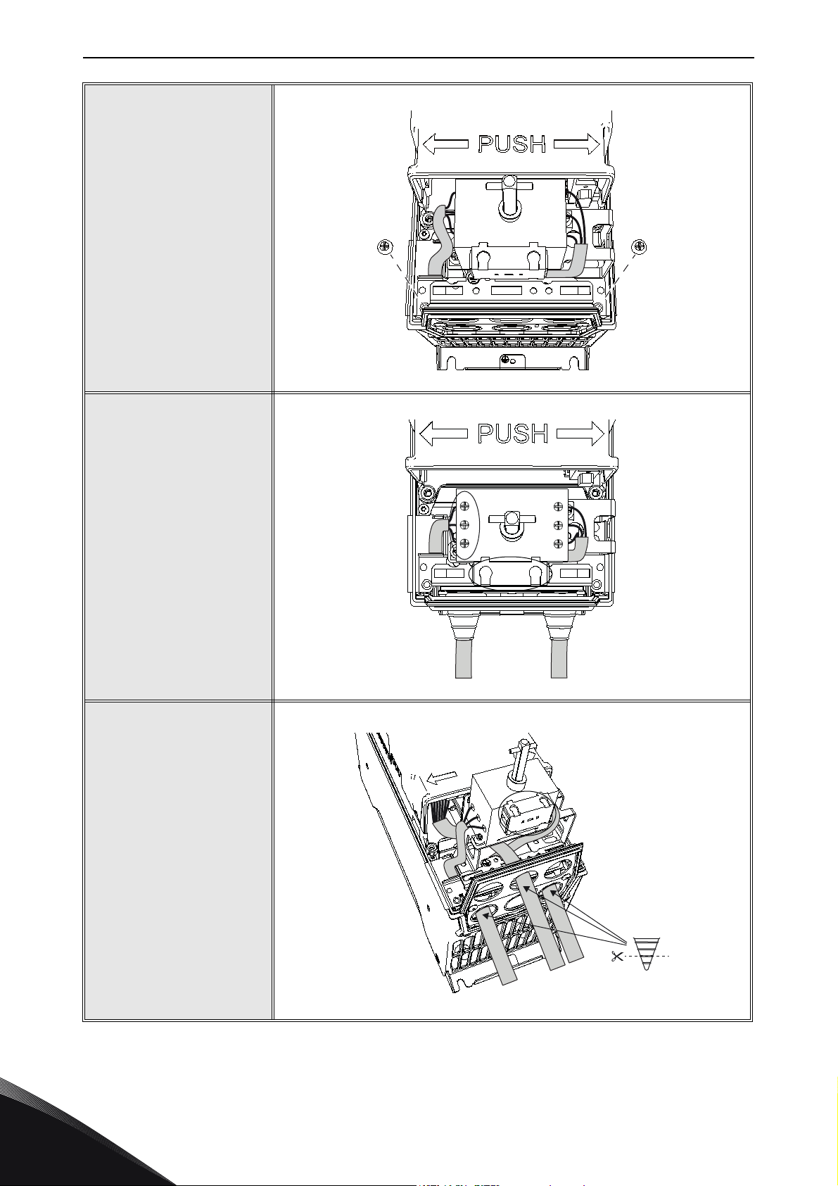
7
Attach the drive supply
switch screws.
8
Tighten the supply cable
screws on the drive supply
switch according to the
tightening torques given in
Table 1 and Table 2.
Please also check the
tightening of the factoryinstalled cable connection
screws on the right side of
the drive supply switch.
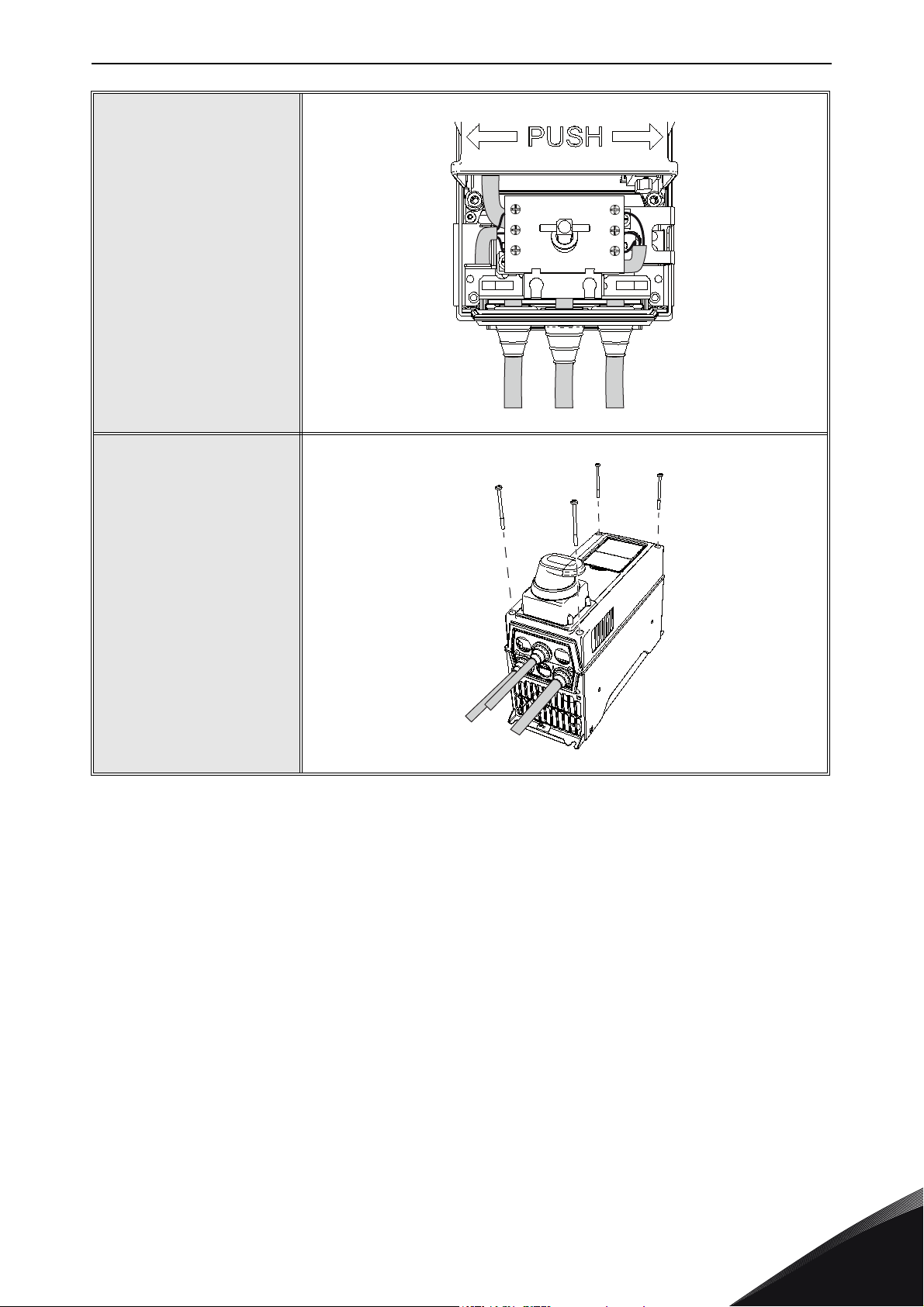
9
MR4: Lead the data
cable “D” under the drive
supply switch and attach it.
MR5-MR7: Lead the data
cable around the drive
supply switch to the
control terminal.
NOTE 1! Protect the data
cable as close to the
terminal as possible with
the cable insulation tube!
NOTE 2! See detailed
cable installation
instructions in the
VACON
manual!
®
100 installation
Local contacts: http://drives.danfoss.com/danfoss-drives/local-contacts/
uk
Page 8
vacon • 8 UK: VACON® 100 drive supply switch
10
The data cable installation
in MR4 seen from above.
11
Close the cover of the
drive.
2T1
4T2
6T3
S
1L1
3L2
5L3
D
M
uk
Local contacts: http://drives.danfoss.com/danfoss-drives/local-contacts/
Page 9
UK: VACON® 100 drive supply switch vacon • 9
3. Cable requirements
The following table shows the maximum sizes for the cables to be used with the drive supply switch.
NOTE! Use only copper cables with the drive supply switch option, no aluminium cables allowed!
Table 1. Cable data for the drive supply switch option
Frame Type
0003 2 - 0008 2 3 x 1.5 + 1.5
0011 2 - 0012 2 3 x 2.5 + 2.5
MR4
0003 5 - 0008 5 3 x 1.5 + 1.5
0009 5 - 0012 5 3 x 2.5 + 2.5
0018 2 - 0024 2 3 x 6 + 6
0031 2 3 x 10 + 10
0016 5 - 0023 5 3 x 6 + 6
MR5
0031 5 3 x 10 + 10
0004 6 - 0006 6 3 x 1.5 + 1.5
0009 6 - 0011 6 3 x 2.5 + 2.5
0048 2 3 x 16 + 16
0062 2 3 x 25 + 16
0038 5 3 x 10 + 10
0046 5 3 x 16 + 16
0061 5 3 x 25 + 16
Maximum mains
and motor cable
size (mm
2
)
Tightening torque of
the drive supply
switch screws (Nm)
0.8 10/70
0.8 16/80
Insulation tube size
for supply cable,
diameter/length (mm)
MR6
MR7
* Cables with heat resistance of at least +90°C must be used.
0018 6 - 0027 6 3 x 10 + 10
0034 6 3 x 16 + 16
0007 7 - 0010 7 3 x 2.5 + 2.5
0013 7 3 x 6 + 6
0018 7 - 0027 7 3 x 10 + 10
0034 7 3 x 16 + 16
0075 2 - 0088 2 3 x 35 + 16
0105 2 3 x 50 + 25*
0072 5 - 0087 5 3 x 35 + 16
0105 5 3 x 50 + 25*
0041 6 3 x 16 + 16
0052 6 - 0062 6 3 x 25 + 16
0041 7 3 x 16 + 16
0052 7 - 0062 7 3 x 25 + 16
2 20/80
6 25/80
Local contacts: http://drives.danfoss.com/danfoss-drives/local-contacts/
uk
Page 10
vacon • 10 UK: VACON® 100 drive supply switch
Table 2. Cable data for the auxiliary switch
Frame Auxiliary switch type Auxiliary switch cable
MR4-7
OA1G10
NO (Normally open)
2x0.75...2.5mm
2x18...14AWG
2
Tightening torque of the auxiliary
switch screws (Nm)
0.8Nm (Pozidrive M3.5 Form 2)
7lb.-in.
4. Mechanical dimensions
Table 3. Mechanical dimensions of the drives with drive supply switch option
Drive size Width (mm) Height (mm) Depth (mm) Weight (kg)
MR4 128 328 270 6.5
MR5 144 419 295 10.5
MR6 195 557 302 20.5
MR7 237 660 332 38.5
uk
Local contacts: http://drives.danfoss.com/danfoss-drives/local-contacts/
Page 11
FI: VACON® 100 -taajuusmuuttajan syöttökytkin vacon • 11
13006.emf
FI: VACON® 100 -TAAJUUSMUUTTAJAN SYÖTTÖKYTKIN
1. Yleistä
Syöttökytkintä käytetään taajuusmuuttajan syöttövirran katkaisemiseen. Tämä lisävaruste
on saatavana taajuusmuuttajakokoihin MR4–MR7, joiden suojausluokka on IP54 ja
enimmäislähtövirta 105 A. Tarkat tiedot ovat taulukossa 1. Taajuusmuuttajan syöttökytkimellä on
CEhyväksyntä 105 ampeeriin ja UL-hyväksyntä 87 ampeeriin saakka.
Taajuusmuuttajan syöttökytkimen toimintaperiaate:
L1
1
f
L2
L3
Taajuusmuuttajan syöttökytkimeen on vakiovarusteena lisätty yksi lisäkytkin, joka on tyyppiä
NO (normaalisti auki). Tämä kytkin auttaa esimerkiksi syöttökytkimen tilatietojen vastaanotossa
PLC-piiriin.
VAROITUS!
Taajuusmuuttajan syöttökytkin on turvalaite. Sitä ei saa käyttää, kun taajuusmuuttaja
on toiminnassa.
Asennusvaiheet kuvataan kohdassa luku 2, kaapelien enimmäiskoot sekä kiristysmomentit
kohdassa luku 3 ja syöttökytkimen sisältävien taajuusmuuttajien mekaaniset mitat kohdassa
luku 4.
2
f
U/T1
V/T2
W/T3
HUOMAUTUS: Kun käytetään Profibus-lisäkorttia OPT-E5 MR4-rungossa, jossa on syöttökytkin,
on suositeltavaa käyttää Phoenix Profibus -liitintä (SUBCON-PLUS-PROFIB/AX/SC 27 44 38 0),
jotta voidaan varmistaa mekaaninen yhteensopivuus.
Local contacts: http://drives.danfoss.com/danfoss-drives/local-contacts/
fi
Page 12
vacon • 12 FI: VACON® 100 -taajuusmuuttajan
M
2. Asennus
1
Irrota taajuusmuuttajan
kansi.
2
Ruuvaa syöttökytkimen
kaksi ruuvia irti ja kallista
kytkintä vasemmalle.
3
Kytke moottorikaapeli M
(katso vaihe 4). Kiristä
ruuvit oikeisiin momentteihin (katso taulukko 1).
Tarkista myös tehtaalla
asennetun syöttökytkimen
kaapelin kiristys!
HUOMAUTUS: Käytä aina
taajuusmuuttajan mukana
toimitettuja kaapelien
läpivientisuojuksia.
Kaapelien yksityiskohtaiset asennusohjeet ovat
VACON
muuttajan asennusoppaassa.
®
100 -taajuus-
fi
Local contacts: http://drives.danfoss.com/danfoss-drives/local-contacts/
Page 13
FI: VACON® 100 -taajuusmuuttajan syöttökytkin vacon • 13
4
Kaapelien kiinnittäminen:
Taita kaapelin suojavaippaa taaksepäin kaapelin
päälle ja kiinnitä kaapeli
asentamalla kaapelikiinnike suojavaipan päälle.
HUOMAUTUS:
Kaapelien yksityiskohtaiset asennusohjeet ovat
®
VACON 100
-taajuusmuuttajan asennusoppaassa.
5
Asenna syöttökaapeli S ja
johda se taajuusmuuttajan
syöttökytkimeen kuvassa
esitetyllä tavalla.
HUOMAUTUS 1:
Suojaa kaapelit eristeputkella mahdollisimman
läheltä syöttökytkintä.
HUOMAUTUS 2:
Kaapelien yksityiskohtaiset
asennusohjeet ovat
VACON
®
100 -taajuusmuut-
tajan asennusoppaassa.
S
M
6
Moottorin ja syöttö-
2T1
4T2
6T3
kaapelin kytkennät
ylhäältä katsottuna.
S
Local contacts: http://drives.danfoss.com/danfoss-drives/local-contacts/
1L1
3L2
5L3
M
fi
Page 14
vacon • 14 FI: VACON® 100 -taajuusmuuttajan
S
M
2T1
4T2
6T3
1L1
3L2
5L3
M
S
D
7
Kiinnitä syöttökytkimen
ruuvit.
8
Kiristä syöttökytkimessä
olevat syöttökaapelin ruuvit oikeisiin momentteihin
(katso taulukko 1 ja
taulukko 2).
Tarkista myös syöttökytkimen oikealla puolella olevat tehtaalla asennetun
kaapelin liitäntäruuvit.
9
MR4: Vie datakaapeli D
syöttökytkimen alle ja
kiinnitä se.
MR5–MR7: Vie datakaapeli syöttökytkimen
ympäri ohjausliittimeen.
HUOMAUTUS 1:
Suojaa datakaapeli eristeputkella mahdollisimman
läheltä liitintä.
HUOMAUTUS 2:
Kaapelien yksityiskohtaiset
asennusohjeet ovat
VACON
tajan asennusoppaassa.
®
100 -taajuusmuut-
fi
Local contacts: http://drives.danfoss.com/danfoss-drives/local-contacts/
Page 15

FI: VACON® 100 -taajuusmuuttajan syöttökytkin vacon • 15
10
Datakaapelin kytkentä
MR4-rungossa ylhäältä
katsottuna.
11
Sulje taajuusmuuttajan
kansi.
2T1
4T2
6T3
S
1L1
3L2
5L3
D
M
Local contacts: http://drives.danfoss.com/danfoss-drives/local-contacts/
fi
Page 16

vacon • 16 FI: VACON® 100 -taajuusmuuttajan
3. Kaapelivaatimukset
Seuraavassa taulukossa esitetään syöttökytkimessä käytettävien kaapeleiden enimmäiskoot.
HUOMAUTUS: Käytä syöttökytkimessä vain kuparikaapeleita. Alumiinikaapelit eivät ole sallittuja.
Taulukko 1. Syöttökytkinlisävarusteen kaapelitiedot.
Runko Tyyppi
0003 2 - 0008 2 3 x 1.5 + 1.5
0011 2 - 0012 2 3 x 2.5 + 2.5
MR4
0003 5 - 0008 5 3 x 1.5 + 1.5
0009 5 - 0012 5 3 x 2.5 + 2.5
0018 2 - 0024 2 3 x 6 + 6
0031 2 3 x 10 + 10
0016 5 - 0023 5 3 x 6 + 6
MR5
0031 5 3 x 10 + 10
0004 6 - 0006 6 3 x 1.5 + 1.5
0009 6 - 0011 6 3 x 2.5 + 2.5
0048 2 3 x 16 + 16
0062 2 3 x 25 + 16
0038 5 3 x 10 + 10
0046 5 3 x 16 + 16
0061 5 3 x 25 + 16
Verkkojännitekaapelin
ja moottorikaapelin
enimmäiskoko (mm
2
)
Syöttökytkimen
ruuvien kiristys-
momentti (Nm)
0.8 10/70
0.8 16/80
Syöttökaapelin
eristeputken koko,
halkaisija/pituus (mm)
MR6
MR7
* Käytettävien kaapelien lämmönkeston on oltava vähintään +90 °C.
Runko Lisäkytkimen tyyppi Lisäkytkimen johdin Lisäkytkimen ruuvien kiristysmomentti
0018 6 - 0027 6 3 x 10 + 10
0034 6 3 x 16 + 16
0007 7 - 0010 7 3 x 2.5 + 2.5
0013 7 3 x 6 + 6
0018 7 - 0027 7 3 x 10 + 10
0034 7 3 x 16 + 16
0075 2 - 0088 2 3 x 35 + 16
0105 2 3 x 50 + 25*
0072 5 - 0087 5 3 x 35 + 16
0105 5 3 x 50 + 25*
0041 6 3 x 16 + 16
0052 6 - 0062 6 3 x 25 + 16
0041 7 3 x 16 + 16
0052 7 - 0062 7 3 x 25 + 16
Taulukko 2. Lisäkytkimen kaapelitiedot
220/80
625/80
fi
MR4-7
OA1G10
NO (Normaalisti auki)
2x0,75...2,5mm
2x18...14AWG
Local contacts: http://drives.danfoss.com/danfoss-drives/local-contacts/
2
0,8Nm (Pozidrive M3,5 Form 2)
7lb.-in.
Page 17

FI: VACON® 100 -taajuusmuuttajan syöttökytkin vacon • 17
4. Mekaaniset mitat
Taulukko 3. Syöttökytkimellä varustettujen taajuusmuuttajien mekaaniset mitat.
Taajuusmuut-
tajan koko
MR4 128 328 270 6,5
MR5 144 419 295 10,5
MR6 195 557 302 20,5
MR7 237 660 332 38,5
Leveys (mm) Korkeus (mm) Syvyys (mm) Paino (kg)
Local contacts: http://drives.danfoss.com/danfoss-drives/local-contacts/
fi
Page 18

vacon • 18 DE: VACON® 100 Netztrennschalter
13006.emf
DE: VACON® 100 NETZTRENNSCHALTER
1. Allgemeines
Der Netztrennschalter wird verwendet, um die Stromzufuhr zum Umrichter abzuschalten.
Verfügbar ist diese Option für die Umrichtergrößen MR4 bis MR7 mit der Schutzart IP54 und einem
maximalen Ausgangsstrom von 105 A (Details siehe Tabelle 1). Der Netztrennschalter entspricht
bis 105 A den CE-Richtlinien und bis 87 A den UL-Richtlinien.
Arbeitsweise des Netztrennschalters:
L1
1
f
L2
L3
Der Netztrennschalter ist standardmäßig mit einem zusätzlichen Hilfsschalter, Typ Schließer (NO),
ausgerüstet. Dieser Kontaktschalter wird u. a. beim Abrufen von Statusinformationen des
Netztrennschalters an die PLC verwendet.
VORSICHT!
Der Netztrennschalter ist eine Sicherheitsvorrichtung. Der Netztrennschalter darf
nicht während des Umrichterbetriebs verwendet werden.
Kapitel 2 enthält die Installationsschritte, die maximalen Kabelgrößen und Anzugsmomente
werden in Kapitel 3 vorgestellt und in Kapitel 4 finden sich die mechanischen Abmessungen der
Umrichter mit Netztrennschalteroption.
2
f
U/T1
V/T2
W/T3
de
HINWEIS: Wird eine Profibus-Zusatzkarte OPT-E5 in einem MR4 mit einem Netztrennschalter
verwendet, ist es empfehlenswert, einen Phoenix Profibus-Konnektor (SUBCON-PLUSPROFIB/AX/SC 27 44 38 0) zu verwenden, um die mechanische Kompatibilität zu gewährleisten.
Local contacts: http://drives.danfoss.com/danfoss-drives/local-contacts/
Page 19

DE: VACON® 100 Netztrennschalter vacon • 19
M
2. Installation
1
Entfernen Sie die Abdeckung des Umrichters.
2
Entfernen Sie die
beiden Schrauben am
Netztrennschalter und
kippen Sie den Schalter
nach links.
3
Schließen Sie das mit „M“
gekennzeichnete Motorkabel an (siehe Schritt 4).
Ziehen Sie die Schrauben
unter Berücksichtigung
der in Tabelle 1 aufgeführten Anzugsmomente
fest. Überprüfen Sie
außerdem, ob das werkseitig installierte
Netztrennschalterkabel
ordnungsgemäß
befestigt ist.
HINWEIS: Verwenden
Sie unbedingt die Kabeldichtungen aus dem
Lieferumfang des
Umrichters. Genaue
Anweisungen zur Kabelinstallation finden Sie im
Installationshandbuch
des VACON
®
100.
Local contacts: http://drives.danfoss.com/danfoss-drives/local-contacts/
de
Page 20

vacon • 20 DE: VACON® 100 Netztrennschalter
4
So befestigen Sie die
Kabel: Schlagen Sie die
Kabelabschirmung zurück
über das Kabel und setzen
Sie anschließend eine
Kabelklemme auf die
Abschirmung, um das
Kabel zu befestigen.
HINWEIS: Genaue
Anweisungen zur Kabelinstallation finden Sie im
Installationshandbuch
des VACON
®
100.
5
Installieren Sie das mit
„S“ gekennzeichnete
Netzkabel und verbinden
Sie es mit dem Netztrennschalter (siehe
Abbildung).
HINWEIS 1: Sichern Sie
die Kabel möglichst nah
am Netztrennschalter
mit einem Isolierrohr.
HINWEIS 2: Genaue
Anweisungen zur Kabelinstallation finden Sie im
Installationshandbuch
®
des VACON
100.
S
M
de
6
Darstellung des installierten Motor- und Netzkabels von oben.
2T1
4T2
6T3
S
Local contacts: http://drives.danfoss.com/danfoss-drives/local-contacts/
1L1
3L2
5L3
M
Page 21

DE: VACON® 100 Netztrennschalter vacon • 21
S
M
2T1
4T2
6T3
1L1
3L2
5L3
M
S
D
7
Ziehen Sie die Schrauben
des Netztrennschalters
fest.
8
Ziehen Sie die Schrauben
des Netzkabels am
Netztrennschalter fest.
Berücksichtigen Sie dabei
die in Tabelle 1 und
Tabelle 2 aufgeführten
Anzugsmomente. Überprüfen Sie außerdem, ob
die werkseitig installierten Kabelverbindungsschrauben auf der rechten
Seite des Netztrennschalters festgezogen sind.
9
MR4: Führen Sie das
mit „D“ gekennzeichnete
Datenkabel unter dem
Netztrennschalter entlang
und befestigen Sie das
Kabel.
MR5-MR7: Führen Sie das
Datenkabel um den Netztrennschalter herum zum
Steueranschluss.
HINWEIS 1: Sichern Sie
das Datenkabel möglichst
nah an der Klemme mit
einem Isolierrohr.
HINWEIS 2: Genaue
Anweisungen zur Kabelinstallation finden Sie im
Installationshandbuch
des VACON
®
100.
Local contacts: http://drives.danfoss.com/danfoss-drives/local-contacts/
de
Page 22

vacon • 22 DE: VACON® 100 Netztrennschalter
10
Das in MR4 installierte
Datenkabel von oben.
11
Schließen Sie die Abdeckung des Umrichters.
2T1
4T2
6T3
S
1L1
3L2
5L3
D
M
de
Local contacts: http://drives.danfoss.com/danfoss-drives/local-contacts/
Page 23

DE: VACON® 100 Netztrennschalter vacon • 23
3. Kabelanforderungen
Die folgende Tabelle enthält die größtmöglichen mit dem Netztrennschalter kompatiblen Kabelgrößen.
HINWEIS: Verwenden Sie ausschließlich Kupferkabel für den Netztrennschalter. Der Einsatz von
Aluminiumkabeln ist unzulässig!
Tabelle 1. Kabelspezifikationen für die Netztrennschalteroption
Baugröße Typ
0003 2 - 0008 2 3 x 1.5 + 1.5
0011 2 - 0012 2 3 x 2.5 + 2.5
MR4
0003 5 - 0008 5 3 x 1.5 + 1.5
0009 5 - 0012 5 3 x 2.5 + 2.5
0018 2 - 0024 2 3 x 6 + 6
0031 2 3 x 10 + 10
0016 5 - 0023 5 3 x 6 + 6
MR5
0031 5 3 x 10 + 10
0004 6 - 0006 6 3 x 1.5 + 1.5
0009 6 - 0011 6 3 x 2.5 + 2.5
0048 2 3 x 16 + 16
0062 2 3 x 25 + 16
0038 5 3 x 10 + 10
0046 5 3 x 16 + 16
Maximale
Netz- und Motorka-
belgrößen (mm
2
)
Anzugsmomente
der Netz-
trennschalter-
schrauben (Nm)
0.8 10/70
0.8 16/80
Größe des Netzkabel-
Isolierrohrs,
Durchmesser/
Länge (mm)
0061 5 3 x 25 + 16
MR6
MR7
* Verwenden Sie Kabel mit einer Hitzebeständigkeit von mindestens +90 °C.
0018 6 - 0027 6 3 x 10 + 10
0034 6 3 x 16 + 16
0007 7 - 0010 7 3 x 2.5 + 2.5
0013 7 3 x 6 + 6
0018 7 - 0027 7 3 x 10 + 10
0034 7 3 x 16 + 16
0075 2 - 0088 2 3 x 35 + 16
0105 2 3 x 50 + 25*
0072 5 - 0087 5 3 x 35 + 16
0105 5 3 x 50 + 25*
0041 6 3 x 16 + 16
0052 6 - 0062 6 3 x 25 + 16
0041 7 3 x 16 + 16
0052 7 - 0062 7 3 x 25 + 16
2 20/80
6 25/80
Local contacts: http://drives.danfoss.com/danfoss-drives/local-contacts/
de
Page 24

vacon • 24 DE: VACON® 100 Netztrennschalter
Tabelle 2. Kabelspezifikationen für den Hilfsschalter
Baugröße Hilfsschaltertyp Hilfsschalterkabel
MR4-7
OA1G10
NO (Schließkontakt)
2 x 0,75–2,5 mm
2 x 18–14AWG
2
Anzugsmomente der
Hilfsschalterschrauben (Nm)
0,8 Nm (Pozidriv M3,5 Form 2)
7lb-in
4. Mechanische Abmessungen
Tabelle 3. Mechanische Abmessungen der Umrichter mit Netztrennschalteroption
Umrichtergröße Breite (mm) Höhe (mm) Tiefe (mm) Gewicht (kg)
MR4 128 328 270 6,5
MR5 144 419 295 10,5
MR6 195 557 302 20,5
MR7 237 660 332 38,5
de
Local contacts: http://drives.danfoss.com/danfoss-drives/local-contacts/
Page 25

FR : Interrupteur d'alimentation du convertisseur de fréquence VACON® 100 vacon •
13006.emf
FR : INTERRUPTEUR D'ALIMENTATION DU CONVERTISSEUR
DE FRÉQUENCE VACON
1. Général
L'interrupteur d'alimentation permet de couper l'alimentation du convertisseur de fréquence.
Cette option est disponible pour les convertisseurs de taille MR4 à MR7 dotés d'un boîtier de classe
IP54 avec un courant d'entrée maximal de 105 A. Pour connaître les caractéristiques exactes, voir
le Tableau 1. L'interrupteur d'alimentation dispose de l'homologation CE pour une intensité
maximale de 105 A et de la certification UL jusqu'à 87 A.
Principe de fonctionnement de l'interrupteur d'alimentation du convertisseur :
®
100
L1
1
f
L2
L3
Un interrupteur auxiliaire supplémentaire, de type normalement ouvert (NO), est ajouté de série
à l'interrupteur d'alimentation du convertisseur. Cet interrupteur de contact facilite la réception
des informations d'état de l'interrupteur d'alimentation du convertisseur pour l'automate, etc.
ATTENT ION !
L'interrupteur d'alimentation du convertisseur est un dispositif de sécurité.
Vous n'êtes pas autorisé à l'utiliser lorsque le convertisseur est en cours
de fonctionnement.
Le Chapitre 2 présente les étapes d'installation, les tailles de câble maximales et les couples
de serrage sont indiqués au Chapitre 3 et les dimensions mécaniques des convertisseurs avec
interrupteur d'alimentation en option sont disponibles au Chapitre 4.
2
f
U/T1
V/T2
W/T3
REMARQUE
de taille MR4 équipé d'un interrupteur d'alimentation, il est recommandé d'utiliser un connecteur
Profibus Phoenix (SUBCON-PLUS-PROFIB/AX/SC 27 44 38 0) pour garantir la compatibilité mécanique.
Local contacts: http://drives.danfoss.com/danfoss-drives/local-contacts/
Lorsque vous utilisez une carte optionnelle Profibus OPT-E5 dans un convertisseur
fr
Page 26

vacon • 26 FR : Interrupteur d'alimentation du
M
2. Installation
1
Déposez le capot du convertisseur de fréquence.
2
Déposez les deux vis de
l'interrupteur d'alimentation du convertisseur et
inclinez celui-ci sur la
gauche.
3
Connectez le câble
moteur "M" (voir Étape 4).
Serrez les vis en respectant les couples de serrage indiqués dans le
Tableau 1. Vérifiez également le serrage du câble
de l'interrupteur d'alimentation du convertisseur installé en usine.
REMARQUE ! Utilisez les
passe-câbles fournis avec
le convertisseur de
fréquence. Reportez-vous
au manuel d'installation
du VACON
obtenir des instructions
détaillées sur l'installation des câbles.
®
100 pour
fr
Local contacts: http://drives.danfoss.com/danfoss-drives/local-contacts/
Page 27

FR : Interrupteur d'alimentation du convertisseur de fréquence VACON® 100 vacon •
S
M
2T1
4T2
6T3
1L1
3L2
5L3
4
Fixation des câbles :
repliez les blindages des
câbles en arrière sur les
câbles, puis fixez les
câbles à l'aide de colliers
apposés sur le blindage.
REMARQUE ! Reportezvous aux instructions
détaillées d'installation
des câbles disponibles
dans le manuel d'installa-
®
tion du VACON
100.
5
Installez le câble d'alimentation "S" et menezle jusqu'à l'interrupteur
d'alimentation du convertisseur, comme illustré.
REMARQUE 1 : Protégez
les câbles à l'aide d'une
gaine d'isolation placée
aussi près que possible de
l'interrupteur d'alimentation du convertisseur.
REMARQUE 2 : Reportezvous aux instructions
détaillées d'installation
des câbles disponibles
dans le manuel d'installa-
tion du VACON
®
100.
S
M
6
Installation du câble
moteur et du câble
d'alimentation vue
de dessus.
Local contacts: http://drives.danfoss.com/danfoss-drives/local-contacts/
fr
Page 28

vacon • 28 FR : Interrupteur d'alimentation du
S
M
2T1
4T2
6T3
1L1
3L2
5L3
M
S
D
7
Serrez les vis de l'interrupteur d'alimentation
du convertisseur.
8
Serrez les vis du câble
d'alimentation sur l'interrupteur d'alimentation
du convertisseur en
respectant les couples de
serrage indiqués dans le
Tableau 1 et le Tableau 2.
Vérifiez également le
serrage des vis de fixation
du câble installées en
usine sur la droite de
l'interrupteur d'alimentation du convertisseur.
9
MR4 : Passez le câble de
données "D" sous l'interrupteur d'alimentation du
convertisseur et fixez-le.
MR5-MR7 : Passez le
câble de données autour
de l'interrupteur
d'alimentation du convertisseur et raccordez-le au
bornier de commande.
REMARQUE 1 : Protégez
le câble de données
à l'aide d'une gaine d'isolation placée aussi près
que possible du bornier.
REMARQUE 2 : Reportezvous aux instructions
détaillées d'installation
des câbles disponibles
dans le manuel d'installa-
tion du VACON
®
100.
fr
Local contacts: http://drives.danfoss.com/danfoss-drives/local-contacts/
Page 29

FR : Interrupteur d'alimentation du convertisseur de fréquence VACON® 100 vacon •
10
Installation du câble
de données dans un
convertisseur de
fréquence de taille MR4
vue de dessus.
11
Refermez le capot
du convertisseur
de fréquence.
2T1
4T2
6T3
S
1L1
3L2
5L3
D
M
Local contacts: http://drives.danfoss.com/danfoss-drives/local-contacts/
fr
Page 30

vacon • 30 FR : Interrupteur d'alimentation du
3. Caractéristiques des câbles
Le tableau suivant indique les tailles maximales des câbles utilisés avec l'interrupteur
d'alimentation du convertisseur.
REMARQUE ! N'utilisez que des câbles en cuivre pour l'installation de l'interrupteur d'alimentation
du convertisseur. N'utilisez en aucun cas de câbles en aluminium !
Tableau 1. Caractéristiques des câbles de l'interrupteur d'alimentation du convertisseur en option
Tai ll e Type
0003 2 - 0008 2 3 x 1.5 + 1.5
0011 2 - 0012 2 3 x 2.5 + 2.5
MR4
0003 5 - 0008 5 3 x 1.5 + 1.5
0009 5 - 0012 5 3 x 2.5 + 2.5
0018 2 - 0024 2 3 x 6 + 6
0031 2 3 x 10 + 10
0016 5 - 0023 5 3 x 6 + 6
MR5
0031 5 3 x 10 + 10
0004 6 - 0006 6 3 x 1.5 + 1.5
0009 6 - 0011 6 3 x 2.5 + 2.5
0048 2 3 x 16 + 16
0062 2 3 x 25 + 16
0038 5 3 x 10 + 10
0046 5 3 x 16 + 16
0061 5 3 x 25 + 16
Taille maximale
des câbles réseau
et moteur (mm
2
)
Couple de serrage des
vis de l'interrupteur
d'alimentation du
convertisseur (Nm)
0.8 10/70
0.8 16/80
Gaine d'isolation du
câble d'alimentation,
diamètre/
longueur (mm)
MR6
MR7
* Des câbles résistant à une chaleur d'au moins +90°C doivent être utilisés.
0018 6 - 0027 6 3 x 10 + 10
0034 6 3 x 16 + 16
0007 7 - 0010 7 3 x 2.5 + 2.5
0013 7 3 x 6 + 6
0018 7 - 0027 7 3 x 10 + 10
0034 7 3 x 16 + 16
0075 2 - 0088 2 3 x 35 + 16
0105 2 3 x 50 + 25*
0072 5 - 0087 5 3 x 35 + 16
0105 5 3 x 50 + 25*
0041 6 3 x 16 + 16
0052 6 - 0062 6 3 x 25 + 16
0041 7 3 x 16 + 16
0052 7 - 0062 7 3 x 25 + 16
220/80
625/80
fr
Local contacts: http://drives.danfoss.com/danfoss-drives/local-contacts/
Page 31

FR : Interrupteur d'alimentation du convertisseur de fréquence VACON® 100 vacon •
Tableau 2. Caractéristiques des câbles de l'interrupteur auxiliaire
Câbles de
l'interrupteur
auxiliaire
2 x 0,75...2,5 mm
2 x 18...14 AWG
Couple de serrage des vis de
l'interrupteur auxiliaire (Nm)
2
0,8 Nm (Pozidrive M3.5 Form 2)
7lb.-in.
Tai ll e
MR4-7
Type d'interrupteur
auxiliaire
OA1G10
NON (Normalement
ouvert)
4. Dimensions mécaniques
Tableau 3. Dimensions mécaniques des convertisseurs équipés de l'interrupteur
d'alimentation du convertisseur en option
Taille du convertisseur Largeur (mm) Hauteur (mm) Profondeur (mm) Poids (kg)
MR4 128 328 270 6,5
MR5 144 419 295 10,5
MR6 195 557 302 20,5
MR7 237 660 332 38,5
Local contacts: http://drives.danfoss.com/danfoss-drives/local-contacts/
fr
Page 32

vacon • 32 SE: VACON® 100 lastbrytare
13006.emf
SE: VACON® 100 LASTBRYTARE
1. Allmänt
Lastbrytaren används när strömtillförseln till omriktaren ska brytas. Detta tillval finns för
omriktarstorlekarna MR4–MR7 med skyddsklass IP54 och maximal utgångsström 105 A, se
exakta data i tabell 1. Lastbrytaren är CE-märkt för upp till 105 A och UL-märkt upp till 87 A.
Lastbrytarens funktionssätt:
L1
1
f
L2
L3
En extra hjälpbrytare, av typen normalt öppen (NO), läggs till i lastbrytaren som standard.
Kontakten underlättar mottagandet av statusinformation om lastbrytare för PLC osv.
SE UPP!
Lastbrytaren är en skyddsfunktion. Den får inte användas när omriktaren är i drift.
I avsnitt 2 beskrivs installationsstegen medan kabelstorlekarna och åtdragningsmomenten
beskrivs i avsnitt 3. Måtten på omriktarna och lastbrytarna anges i avsnitt 4.
OBS! När tilläggskortet Profibus OPT-E5 används i MR4 med en lastbrytare rekommenderar vi att
använda Phoenix Profibus-kontakten (SUBCON-PLUS-PROFIB/AX/SC 27 44 38 0) för största möjliga
mekaniska kompatibilitet.
2
f
U/T1
V/T2
W/T3
se
Local contacts: http://drives.danfoss.com/danfoss-drives/local-contacts/
Page 33

SE: VACON® 100 lastbrytare vacon • 33
M
2. Installation
1
Ta bort kåpan över
omriktaren.
2
Ta bort de båda skruvarna
till lastbrytaren och luta
brytaren åt vänster.
3
Anslut motorkabeln ”M”
(se steg 4). Dra åt skruvarna enligt momentangivelserna i tabell 1.
Kontrollera också att den
fabriksmonterade kabeln
till lastbrytaren sitter
ordentligt.
OBS! Kom ihåg att
använda de genomföringar som medföljer
omriktaren, se installationshandboken för
VACON
anvisningar om kabelinstallation.
®
100 för utförliga
Local contacts: http://drives.danfoss.com/danfoss-drives/local-contacts/
se
Page 34

vacon • 34 SE: VACON® 100 lastbrytare
4
Anslutning av kablarna:
vik ned kabelstrumpan
över kabeln och fäst
kabeln med en kabelklämma på strumpan.
OBS! Se utförliga
anvisningar om
kabelinstallation
i installationshandboken
®
till VACON
100!
5
Installera nätkabeln ”S”
och dra den till lastbrytaren enligt figuren.
ANMÄRKNING 1!
Skydda kablarna med ett
isolationsrör så nära lastbrytaren som möjligt.
ANMÄRKNING 2!
Se utförliga anvisningar
om kabelinstallation
i installationshandboken
till VACON
®
100!
S
M
se
6
Motor- och nätkabelinstallation sedd ovanifrån.
2T1
4T2
6T3
S
Local contacts: http://drives.danfoss.com/danfoss-drives/local-contacts/
1L1
3L2
5L3
M
Page 35

SE: VACON® 100 lastbrytare vacon • 35
S
M
2T1
4T2
6T3
1L1
3L2
5L3
M
S
D
7
Fäst lastbrytarens
skruvar.
8
Dra åt skruvarna till lastbrytarens kabel enligt
momentangivelserna
i tabell 1 och tabell 2.
Kontrollera också att de
fabriksmonterade kabelanslutningsskruvarna på
höger sida om lastbrytaren sitter ordentligt.
9
MR4: Dra ned
datakabeln ”D” under
lastbrytaren och fäst den.
MR5–MR7: Dra datakabeln runt lastbrytaren
till styrplinten.
ANMÄRKNING 1! Skydda
datakabeln med kabelisolationsröret så nära
plinten som möjligt.
ANMÄRKNING 2!
Se utförliga anvisningar
om kabelinstallation
i installationshandboken
till VACON
®
100!
Local contacts: http://drives.danfoss.com/danfoss-drives/local-contacts/
se
Page 36

vacon • 36 SE: VACON® 100 lastbrytare
10
Datakabelinstallationen
i MR4 sedd ovanifrån.
11
Stäng kåpan över
omriktaren.
2T1
4T2
6T3
S
1L1
3L2
5L3
D
M
se
Local contacts: http://drives.danfoss.com/danfoss-drives/local-contacts/
Page 37

SE: VACON® 100 lastbrytare vacon • 37
3. Krav på kablar
Följande tabell visar de största storlekarna på kablar som ska användas tillsammans med lastbrytaren.
OBS! Använd endast kopparkablar tillsammans med lastbrytaren. Aluminiumkablar är inte tillåtna!
Tabell 1. Kabeldata för lastbrytare
Chassi Typ
0003 2 - 0008 2 3 x 1.5 + 1.5
MR4
MR5
MR6
0011 2 - 0012 2 3 x 2.5 + 2.5
0003 5 - 0008 5 3 x 1.5 + 1.5
0009 5 - 0012 5 3 x 2.5 + 2.5
0018 2 - 0024 2 3 x 6 + 6
0031 2 3 x 10 + 10
0016 5 - 0023 5 3 x 6 + 6
0031 5 3 x 10 + 10
0004 6 - 0006 6 3 x 1.5 + 1.5
0009 6 - 0011 6 3 x 2.5 + 2.5
0048 2 3 x 16 + 16
0062 2 3 x 25 + 16
0038 5 3 x 10 + 10
0046 5 3 x 16 + 16
0061 5 3 x 25 + 16
0018 6 - 0027 6 3 x 10 + 10
Största
nätkabel- och
motorkabelstorlek
(mm
2
)
Åtdragningsmoment
för skruvarna till
lastbrytaren (Nm)
0.8 10/70
0.8 16/80
220/80
Storlek på
isolationsrör
för nätkabel,
diameter/längd (mm)
0034 6 3 x 16 + 16
0007 7 - 0010 7 3 x 2.5 + 2.5
0013 7 3 x 6 + 6
0018 7 - 0027 7 3 x 10 + 10
0034 7 3 x 16 + 16
0075 2 - 0088 2 3 x 35 + 16
0105 2 3 x 50 + 25*
0072 5 - 0087 5 3 x 35 + 16
0105 5 3 x 50 + 25*
MR7
0041 6 3 x 16 + 16
0052 6 - 0062 6 3 x 25 + 16
0041 7 3 x 16 + 16
0052 7 - 0062 7 3 x 25 + 16
* Använd kablar som klarar minst +90 °C.
625/80
Local contacts: http://drives.danfoss.com/danfoss-drives/local-contacts/
se
Page 38

vacon • 38 SE: VACON® 100 lastbrytare
Tabell 2. Kabeldata för hjälpbrytaren
Byggstorlek Hjälpbrytartyp Hjälpbrytarkabel
MR4-7
OA1G10
NO (Normally open)
2x0,75...2,5 mm
2x18...14 AWG
Åtdragningsmoment för skruvarna
på hjälpbrytaren (Nm)
2
0,8 Nm (Pozidrive M3.5 Form 2)
7lb.-in.
4. Mekaniska mått
Tabel l 3. Mekan iska mått för omriktarna med lastbrytare
Omriktarstorlek Bredd (mm) Höjd (mm) Djup (mm) Vikt (kg)
MR4 128 328 270 6,5
MR5 144 419 295 10,5
MR6 195 557 302 20,5
MR7 237 660 332 38,5
se
Local contacts: http://drives.danfoss.com/danfoss-drives/local-contacts/
Page 39

NL: Hoofdschakelaar VACON® 100 frequentieregelaar vacon • 39
13006.emf
NL: HOOFDSCHAKELAAR VACON® 100 FREQUENTIEREGELAAR
1. Algemeen
Deze hoofdschakelaar wordt gebruikt voor het uitschakelen van de ingangsstroom van
de frequentieregelaar. Deze optie is beschikbaar voor frequentieregelaars MR4–MR7 met
behuizingsklasse IP54 en een maximale uitgangsstroom van 105 A (zie Tabel 1 voor de
exacte gegevens). De hoofdschakelaar is voorzien van CE-goedkeuring tot 105 A en heeft
een ULvermelding voor vermogens tot 87 A.
Werkingsprincipe van de hoofdschakelaar:
L1
1
f
L2
L3
De hoofdschakelaar is standaard voorzien van één extra hulpschakelaar (maakcontact).
Deze contactschakelaar helpt bij het ontvangen van statusinformatie over de hoofdschakelaar
voor PLC's etc.
LET OP!
De hoofdschakelaar is een veiligheidsapparaat. Het is niet toegestaan om de
hoofdschakelaar te gebruiken wanneer de frequentieregelaar in bedrijf is.
Hoofdstuk 2 toont de installatiestappen. De maximale kabellengten en de aandraaimomenten
worden aangegeven in Hoofdstuk 3 en de fysieke afmetingen van frequentieregelaars met de
optionele hoofdschakelaar worden aangegeven in Hoofdstuk 4.
2
f
U/T1
V/T2
W/T3
OPMERKING! Bij gebruik van een MR4-frequentieregelaar met PROFIBUS-optiekaart OPT-E5
in combinatie met een hoofdschakelaar wordt een Phoenix PROFIBUS-connector (SUBCONPLUS-PROFIB/AX/SC 27 44 38 0) aanbevolen voor mechanische compatibiliteit.
Local contacts: http://drives.danfoss.com/danfoss-drives/local-contacts/
nl
Page 40

vacon • 40 NL: Hoofdschakelaar VACON® 100
M
2. Installatie
1
Verwijder de kap van
de frequentieregelaar.
2
Verwijder de twee
schroeven van de
hoofdschakelaar en
kantel de schakelaar
naar links.
3
Sluit de motorkabel 'M'
aan (zie Stap 4). Draai
de schroeven aan volgens
de aandraaimomenten in
Tabel 1. Controleer
bovendien of de af fabriek
geïnstalleerde kabel van
de hoofdschakelaar
correct is aangedraaid!
OPMERKING!
Zorg dat u de met de
frequentieregelaar meegeleverde rubberen doorvoertules gebruikt. Zie de
installatiehandleiding van
de VACON
gebreide instructies met
betrekking tot de installatie van de kabels.
®
100 voor uit-
nl
Local contacts: http://drives.danfoss.com/danfoss-drives/local-contacts/
Page 41

NL: Hoofdschakelaar VACON® 100 frequentieregelaar vacon • 41
4
De kabels bevestigen:
vouw de kabelafscherming terug op de kabel en
bevestig de kabel met een
kabelklem op de afscherming.
OPMERKING! Zie de
installatiehandleiding van
®
de VACON
100 voor uitgebreide instructies met
betrekking tot de installatie van de kabels.
5
Monteer de voedingskabel 'S' en leid deze naar
de hoofdschakelaar zoals
getoond in de afbeelding.
OPMERKING 1! Bescherm
de kabels met een isolatiehuls zo dicht mogelijk
bij de hoofdschakelaar.
OPMERKING 2! Zie de
installatiehandleiding van
de VACON
®
100 voor uitgebreide instructies met
betrekking tot de installatie van de kabels.
S
M
6
De motor en de installatie
2T1
4T2
6T3
van de voedingskabel van
bovenaf gezien.
S
Local contacts: http://drives.danfoss.com/danfoss-drives/local-contacts/
1L1
3L2
5L3
M
nl
Page 42

vacon • 42 NL: Hoofdschakelaar VACON® 100
S
M
2T1
4T2
6T3
1L1
3L2
5L3
M
S
D
7
Bevestig de schroeven van
de hoofdschakelaar.
8
Draai de schroeven van
de voedingskabel op de
hoofdschakelaar aan
volgens de aandraaimomenten in Tabel 1 en
Tabel 2. Controleer ook
het aandraaimoment van
de in de fabriek geïnstalleerde kabelbevestigingsschroeven aan de
rechterkant van de
hoofdschakelaar.
9
MR4: Leid de gegevenska-
bel 'D' onder de hoofdschakelaar door en
bevestig deze.
MR5-MR7: Leid de
gegevenskabel rondom
de hoofdschakelaar
naar de besturingsklem.
OPMERKING 1! Bescherm
de gegevenskabel met
een isolatiehuls zo dicht
mogelijk bij de
hoofdschakelaar.
OPMERKING 2! Zie de
installatiehandleiding
van de VACON
uitgebreide instructies
met betrekking tot de
installatie van de kabels.
®
100 voor
nl
Local contacts: http://drives.danfoss.com/danfoss-drives/local-contacts/
Page 43
NL: Hoofdschakelaar VACON® 100 frequentieregelaar vacon • 43
10
De installatie van de
gegevenskabel bij MR4,
van bovenaf gezien.
11
Sluit de kap van de
frequentieregelaar.
2T1
4T2
6T3
S
1L1
3L2
5L3
D
M
Local contacts: http://drives.danfoss.com/danfoss-drives/local-contacts/
nl
Page 44

vacon • 44 NL: Hoofdschakelaar VACON® 100
3. Kabelvereisten
De volgende tabel toont de maximale maten voor de kabels die gebruikt mogen worden met de
hoofdschakelaar.
OPMERKING! Gebruik de hoofdschakelaar uitsluitend met koperen kabels. Aluminium kabels zijn
niet toegestaan.
Tabel 1. Kabelgegevens voor de hoofdschakelaar
Frame Type
0003 2 - 0008 2 3 x 1.5 + 1.5
MR4
MR5
MR6
0011 2 - 0012 2 3 x 2.5 + 2.5
0003 5 - 0008 5 3 x 1.5 + 1.5
0009 5 - 0012 5 3 x 2.5 + 2.5
0018 2 - 0024 2 3 x 6 + 6
0031 2 3 x 10 + 10
0016 5 - 0023 5 3 x 6 + 6
0031 5 3 x 10 + 10
0004 6 - 0006 6 3 x 1.5 + 1.5
0009 6 - 0011 6 3 x 2.5 + 2.5
0048 2 3 x 16 + 16
0062 2 3 x 25 + 16
0038 5 3 x 10 + 10
0046 5 3 x 16 + 16
0061 5 3 x 25 + 16
0018 6 - 0027 6 3 x 10 + 10
0034 6 3 x 16 + 16
Maximale maat
voor voedings- en
motorkabel (mm
Aandraaimoment van
de schroeven van de
2
hoofdschakelaar (Nm)
)
0.8 10/70
0.8 16/80
220/80
Maat isolatiehuls
voor voedingskabel,
doorsnede/lengte (mm)
nl
0007 7 - 0010 7 3 x 2.5 + 2.5
0013 7 3 x 6 + 6
0018 7 - 0027 7 3 x 10 + 10
0034 7 3 x 16 + 16
0075 2 - 0088 2 3 x 35 + 16
0105 2 3 x 50 + 25*
0072 5 - 0087 5 3 x 35 + 16
0105 5 3 x 50 + 25*
MR7
0041 6 3 x 16 + 16
0052 6 - 0062 6 3 x 25 + 16
0041 7 3 x 16 + 16
0052 7 - 0062 7 3 x 25 + 16
* Gebruik kabels die bestand zijn tegen ten minste +90 °C.
Local contacts: http://drives.danfoss.com/danfoss-drives/local-contacts/
625/80
Page 45
NL: Hoofdschakelaar VACON® 100 frequentieregelaar vacon • 45
Tabel 2. Kabelgegevens voor de hulpschakelaar
Frame Type hulpschakelaar Kabel hulpschakelaar
MR4-7
OA1G10
NO (normaal open)
2 x 0,75...2,5 mm
2 x 18...14 AWG
4. Fysieke afmetingen
Tabel 3. Fysieke afmetingen van de frequentieregelaars met optionele hoofdschakelaar
Grootte
frequentieregelaar
MR4 128 328 270 6,5
MR5 144 419 295 10,5
MR6 195 557 302 20,5
MR7 237 660 332 38,5
Breedte (mm) Hoogte (mm) Diepte (mm) Gewicht (kg)
Aandraaimoment voor schroeven
hulpschakelaar (Nm)
2
0,8 Nm (Pozidriv M3,5 Form 2)
7 lb-in
Local contacts: http://drives.danfoss.com/danfoss-drives/local-contacts/
nl
Page 46

www.danfoss.com
Vacon Ltd
Member of the Danfoss Group
Runsorintie 7
65380 Vaasa
Finland
Document ID:
DPD01421D
Rev. D
 Loading...