

Application Guide
VACON® 100 FLOW
drives.danfoss.com


VACON® 100 FLOW
Application Guide
Contents
1
Introduction 11
1.1
Purpose of this Application Guide 11
Manual and Software Version 11
1.2
Additional Resources 11
1.3
1.4
Parameter Table Reading Guide 11
1.5
Functions of the AC Drive 12
1.6
Start-up Quick Guide 13
1.6.1
Start-Up Wizard 13
User Interfaces 14
2
Description of the Control Panel 14
2.1
Control Panel and the Keypad 14
2.1.1
Displays of the Control Panel 14
2.1.2
Contents
Menu Structure 15
2.2
2.3
Graphical Display 18
2.3.1
Editing the Text Values 18
2.3.2
Editing the Numerical Values 18
2.3.3
Selecting More than 1 Value 19
2.3.4
Resetting a Fault 19
2.3.5
[FUNCT] Button 19
2.3.5.1
2.3.5.2
2.3.5.3
2.3.5.4
2.3.5.5
2.3.6
Copying the Parameters of an AC Drive 22
2.3.7
Comparing the Parameters 22
2.3.8
Reading Help Texts 23
2.3.9
Using the Favourites Menu 24
Different Control Places 19
Changing the Control Place 20
Going into the Control Page 20
Changing the Rotation Direction 21
Using the Quick Edit Function 21
2.4
Text Display 24
2.4.1
Editing the Text Values 24
2.4.2
Editing the Numerical Values 24
2.4.3
Resetting a Fault 19
2.4.4
[FUNCT] Button 25
2.4.4.1
2.4.4.2
2.4.4.3
Different Control Places 19
Changing the Control Place 25
Going into the Control Page 26
AB298035655957en-000101/DPD01083 | 3Danfoss A/S © 2021.05

VACON® 100 FLOW
Application Guide
2.4.4.4
2.4.4.5
2.5
VACON® Live PC Tool 27
3
Applications 28
3.1
Using the Applications 28
3.2
Standard and HVAC Applications 28
3.3
PID Control Application 32
3.4
Multi-pump (Single Drive) Application 36
3.5
Multi-pump (Multidrive) Application 43
4
Wizards 67
4.1
Application Wizards 67
4.1.1
Standard Application Wizard 67
4.1.2
HVAC Application Wizard 67
Changing the Rotation Direction 26
Using the Quick Edit Function 21
Contents
4.1.3
PID Control Application Wizard 68
4.1.4
Multi-pump (Single Drive) Application Wizard 69
4.1.5
Multi-pump (Multidrive) Application Wizard 70
4.2
Function Wizards 72
4.2.1
Wizards in Menu 1.1 72
4.2.2
Fire Mode Wizard 72
5
Monitor Menu 73
5.1
Uses of the Monitor Menu 73
5.2
Multimonitor Monitoring 73
5.2.1
Changing the Items to Monitor 73
5.3
Trend Curve Monitoring 73
5.3.1
Uses of the Trend Curve 73
5.3.2
Changing the Values in Trend Curve Monitoring 73
5.3.3
Stopping the Progression of the Curve 74
5.3.4
Trend Curve Parameters 75
5.4
Basic Monitoring 75
5.4.1
Uses of the Basic Monitoring 75
5.4.2
Basic Monitoring Parameters 75
5.5
I/O Monitoring 76
5.6
Temperature Inputs 76
5.7
Extras and Advanced 77
5.8
Timer Functions Monitoring 79
5.9
PID Controller Monitoring 79
AB298035655957en-000101/DPD010834 | Danfoss A/S © 2021.05

VACON® 100 FLOW
Application Guide
5.10
External PID Controller Monitoring 80
5.11
Multi-pump Monitoring 80
5.12
Monitoring of Maintenance Counters 81
5.13
Fieldbus Process Data Monitoring 81
5.14
Drive Customizer Monitoring 82
5.15
Condition-based Monitoring 83
6
Parameters Menu 85
6.1
Group 3.1: Motor Settings 85
6.2
Group 3.2: Start/Stop Setup 87
6.3
Group 3.3: References 88
6.4
Group 3.4: Ramps and Brakes Setup 91
6.5
Group 3.5: I/O Configuration 92
6.6
Group 3.6: Fieldbus Data 99
6.7
Group 3.7: Prohibit Frequencies 101
Contents
6.8
Group 3.8 Supervisions 101
6.9
Group 3.9: Protections 102
6.10
Group 3.10: Automatic Reset 105
6.11
Group 3.11: Application Settings 106
6.12
Group 3.12: Timer Functions 107
6.13
Group 3.13: PID Controller 109
6.14
Group 3.14: External PID Controller 117
6.15
Group 3.15: Multi-pump 120
6.16
Group 3.16: Maintenance Counters 122
6.17
Group 3.17: Fire Mode 123
6.18
Group 3.18: Motor Preheat Parameters 124
6.19
Group 3.19: Drive Customizer 124
6.20
Group 3.21: Pump Control 124
6.21
Group 3.23: Advanced Harmonic Filter 127
6.22
Group 3.24: Condition-based Monitoring 127
7
Diagnostics Menu 132
7.1
Faults 132
7.1.1
Uses of the Active Faults Submenu 132
7.1.2
Reset Faults 132
7.1.2.1
7.1.2.2
7.1.2.3
7.1.3
Uses of the Fault History 133
Resetting Faults with the [BACK/RESET] Button 132
Resetting Faults with a Parameter on the Graphical Display 132
Resetting Faults with a Parameter on the Text Display 132
AB298035655957en-000101/DPD01083 | 5Danfoss A/S © 2021.05

VACON® 100 FLOW
Application Guide
7.1.3.1
7.1.3.2
7.2
Counters 134
7.2.1
Using the Counters 134
7.2.2
Total Counters 134
7.2.3
Trip Counters 135
7.3
Software Info 136
7.4
Drive Info 136
7.5
Unit Status 136
8
I/O and Hardware Menu 137
8.1
Basic I/O 137
8.2
Option Board Slots 137
8.3
Real-time Clock 138
8.4
Simple Network Time Protocol (SNTP) 138
Examining the Fault History on the Graphical Display 133
Examining the Fault History on the Text Display 133
Contents
8.5
Power Unit Settings 139
8.6
Keypad 139
8.7
Fieldbus 140
8.8
Fieldbus General 142
8.9
STO 143
8.10
Fieldbus Redundancy 143
9
User Settings, Favourites, and User Level Menus 144
9.1
User Settings 144
9.1.1
User Settings Parameters 144
9.1.2
Parameter Back-up Parameters 144
9.1.3
Parameter Compare Parameters 145
9.1.4
License Parameters 145
9.2
Favourites 145
9.2.1
Using the Favourites Menu 145
9.2.2
Adding an Item to the Favourites 145
9.2.3
Removing an Item from the Favourites 145
9.3
User Levels 146
9.3.1
Using the User Levels Menu 146
9.3.2
The User Level Parameters 146
9.3.3
Changing the Access Code of the User Levels 146
10
Monitoring Value Descriptions 148
10.1
Multimonitor 148
AB298035655957en-000101/DPD010836 | Danfoss A/S © 2021.05

VACON® 100 FLOW
Application Guide
10.2
Basic 149
10.3
I/O 150
10.4
Temperature Inputs 151
10.5
Extras and Advanced 152
10.6
Timer Functions 153
10.7
PID Controller 154
10.8
External PID Controller 155
10.9
Multi-pump 155
10.10
Maintenance Counters 156
10.11
Fieldbus Data 156
10.12
Drive Customizer 159
10.13
Condition-based Monitoring 160
10.13.1
Baseline Data 160
10.13.2
Stator Winding Monitor 161
Contents
10.13.3
Vibration 161
10.13.4
Load 162
11
Parameter Descriptions 163
11.2
Trend Curve 163
11.3
Motor Settings 164
11.3.1
Motor Nameplate Parameters 164
11.3.2
Motor Control Parameters 164
11.3.3
Motor Limits 168
11.3.4
Open Loop Parameters 168
11.3.5
I/f Start Function 171
11.3.6
Torque Stabilator Function 172
11.4
Start/Stop Setup 173
11.4.1
Start and Stop Commands in Different Control Places 173
11.5
References 181
11.5.1
Frequency Reference 181
11.5.2
Preset Frequencies 182
11.5.3
Motor Potentiometer Parameters 185
11.5.4
Flushing Parameters 186
11.6
Ramps and Brakes Setup 186
11.6.1
Ramp 1 186
11.6.2
Ramp 2 187
11.6.3
Start Magnetizing 189
11.6.4
DC Brake 189
AB298035655957en-000101/DPD01083 | 7Danfoss A/S © 2021.05

VACON® 100 FLOW
Application Guide
11.6.5
Flux Braking 189
11.7
I/O Configuration 190
11.7.1
Programming of Digital and Analog Inputs 190
11.7.1.1
11.7.1.2
11.7.1.3
11.7.1.4
11.7.1.5
11.7.1.6
11.7.1.7
11.7.2
Descriptions of Signal Sources 196
11.7.3
Default Functions of Programmable Inputs 197
11.7.4
Digital Inputs 197
11.7.5
Analog Inputs 202
Contents
General Information on the Programming 190
Programming of Digital Inputs 191
Programming of Digital Inputs in the Graphical Display 193
Programming of Digital Inputs in the Text Display 193
Programming of Analog Inputs 194
Programming of Analog Inputs in the Graphical Display 195
Programming of Analog Inputs in the Text Display 196
11.7.6
Digital Outputs 206
11.7.7
Analog Outputs 209
11.8
Fieldbus Data 212
11.9
Prohibit Frequencies 214
11.10
Supervisions 216
11.11
Protections 216
11.11.1
General 216
11.11.2
Motor Thermal Protections 218
11.11.3
Motor Stall Protection 221
11.11.4
Underload (Dry Pump) Protection 222
11.11.5
Quick Stop 224
11.11.6
AI Low Protection 225
11.12
Automatic Reset 226
11.13
Application Settings 229
11.14
Timer Functions 229
11.14.1
Introduction to Timer Functions 229
11.14.2
Time Channels, Intervals, and Timers 230
11.14.3
Editing an Interval 232
11.15
PID Controller 233
11.15.1
Basic Settings 233
11.15.2
Setpoints 235
11.15.3
Feedback 236
11.15.4
Feedforward 236
11.15.5
Sleep Function 237
AB298035655957en-000101/DPD010838 | Danfoss A/S © 2021.05

VACON® 100 FLOW
Application Guide
11.15.6
Feedback Supervision 240
11.15.7
Pressure Loss Compensation 242
11.15.8
Soft Fill 243
11.15.9
Input Pressure Supervision 244
11.15.10
Sleep Function When No Demand Is Detected 246
11.15.11
Multi-setpoint 248
11.16
External PID Controller 249
11.17
Multi-pump Function 250
11.17.1
The Multi-pump Function 250
11.17.1.1
11.17.2
System Configuration 251
11.17.3
Interlocks 256
11.17.4
Feedback Sensor Connection in a Multi-pump System 256
11.17.5
Overpressure Supervision 263
Contents
Commissioning Multi-pump (Multidrive) 250
11.17.6
Pump Run-time Counters 264
11.17.7
Advanced Settings 265
11.18
Maintenance Counters 266
11.18.1
The Maintenance Counters 266
11.19
Fire Mode 267
11.19.1
The Fire Mode Function 267
11.20
Motor Preheat Function 270
11.21
Drive Customizer 271
11.22
Pump Control 271
11.22.1
Auto-Cleaning 271
11.22.2
Jockey Pump 273
11.22.3
Priming Pump 274
11.22.4
Anti-blocking Function 275
11.22.5
Frost Protection 275
11.22.6
Flow Switch 276
11.23
Advanced Harmonic Filter 277
11.24
Condition-based Monitoring 277
11.24.1
Introduction to Condition-based Monitoring 277
11.24.1.1
11.24.6
Manual Run 279
11.24.7
Stator Winding Monitoring 280
11.24.8
Threshold Value 280
11.24.9
Warning and Alarm/Fault Stages 281
11.25
Default Values of Parameters in the Different Applications 286
Stages of Condition-based Monitoring 278
AB298035655957en-000101/DPD01083 | 9Danfoss A/S © 2021.05

VACON® 100 FLOW
Application Guide
12
Fault Tracing 292
Fault Types 292
12.1
12.2
Alarms and Warnings 292
Fault Codes 292
12.3
12.4
Total and Trip Counters 317
12.4.1
Operating Time Counter 317
12.4.2
Operating Time Trip Counter 318
12.4.3
Run Time Counter 318
12.4.4
Power on Time Counter 319
12.4.5
Energy Counter 319
12.4.6
Energy Trip Counter 320
Contents
AB298035655957en-000101/DPD0108310 | Danfoss A/S © 2021.05
Edition
Software version
DPD01083H
FW0159V024
NOTE! Download the English and French product guides with applicable safety, warning and caution information from https://
www.danfoss.com/en/service-and-support/.
REMARQUE Vous pouvez télécharger les versions anglaise et française des guides produit contenant l'ensemble des informations
de sécurité, avertissements et mises en garde applicables sur le site https://www.danfoss.com/en/service-and-support/.
Index
Min Max Unit Default
ID Description
Parameter
e30bg858.10
A
B
C
D E F G H
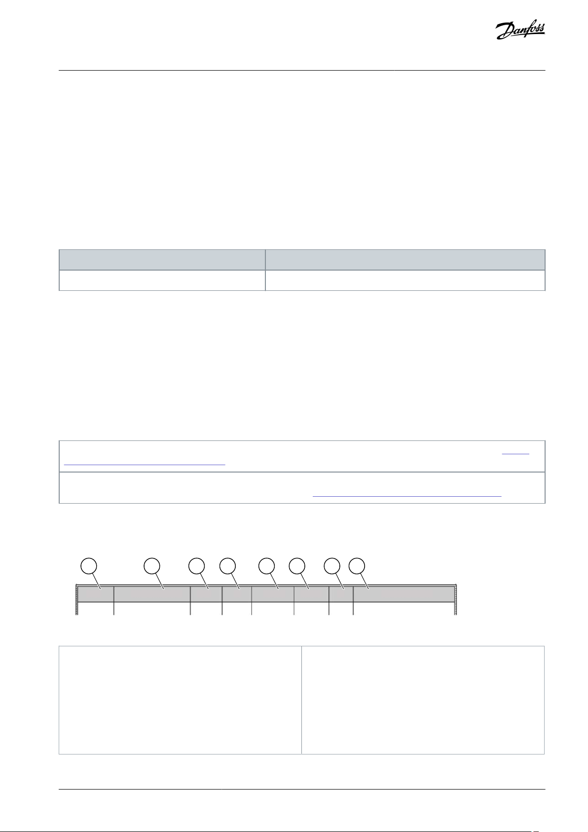
A
The location of the parameter in the menu, that is,
the parameter number.
B
The name of the parameter.
C
The minimum value of the parameter.
D
The maximum value of the parameter.
E
The unit of the value of the parameter. The unit
shows if it is available.
F
The value that was set in the factory.
G
The ID number of the parameter.
H
A short description of the values of the parameter
and/or its function.
VACON® 100 FLOW
Application Guide
Introduction
1 Introduction
1.1 Purpose of this Application Guide
This Application Guide provides information for configuring the system, controlling the AC drive, accessing parameters, programming, and troubleshooting of the AC drive. It is intended for use by qualified personnel. Read and follow the instructions to use the
drive safely and professionally. Pay particular attention to the safety instructions and general warnings that are provided in this
manual and other documentation delivered with the drive.
1.2 Manual and Software Version
This manual is regularly reviewed and updated. All suggestions for improvement are welcome.
The original language of this manual is English.
Table 1: Manual and Software Version
1.3 Additional Resources
Other resources are available to understand advanced AC drive functions and operation.
•
VACON® 100 Wall-mounted Drives Operating Guide
•
VACON® 100 Enclosed Drives Installation Manual
VACON® 100 IP00 Drive Modules Installation Manual
•
VACON® 100 X Installation Manual
•
Instructions for operation with option boards and other optional equipment.
•
Supplementary publications and manuals are available from Danfoss.
For US and Canadian markets:
1.4 Parameter Table Reading Guide
This manual includes a large quantity of parameter tables. These instructions tell you how to read the tables.
Illustration 1: Parameter Table Reading Guide
AB298035655957en-000101 / DPD01083 | 11Danfoss A/S © 2021.05

VACON® 100 FLOW
Application Guide
1.5 Functions of the AC Drive
•
Easy setup functions
-
Applications with preset parameters and I/O configuration for your process: Standard, HVAC, PID control, Multi-pump
-
Start-up wizards for fast and easy parameterization
•
Navigation functions
-
The [FUNCT] button for an easy change between the local and the remote control place (I/O or fieldbus)
-
A control page to operate and monitor of the most important values quickly
•
Advanced monitoring functions
-
Multimonitor
-
Trend curve
•
Fieldbus and I/O control
•
Motor control
-
Open loop control with frequency reference
-
Support for induction, permanent magnet, and synchronous reluctance motors
-
Identification run for setup of motor parameters
-
Flux and DC brake
•
Start and stop logic configuration
•
Reference selection and handling
-
8 preset frequencies
-
Motor potentiometer functions
-
A flush function
-
2 programmable ramp times
-
2 supervisions
-
3 ranges of prohibited frequencies
-
A forced stop
•
PID control
-
An external PID controller is available. Use it, for example, to control a valve with the I/O of the AC drive.
-
A sleep mode function that automatically enables and disables the operation of the drive to save energy
-
A 2-zone PID controller with 2 different feedback signals: minimum and maximum control
-
2 setpoint sources for the PID control. Selection to be made with a digital input.
-
A function for PID setpoint boost
-
A feedforward function to make the response to the process changes better
•
Pump control
-
A multi-pump control for the single drive and multidrive systems
-
The multimaster and multifollower modes in the multidrive system
-
A multi-pump system that uses a real time clock to autochange the pumps
-
Priming pump control, jockey pump control, pump impeller auto-cleaning, pump input pressure supervision, and frost protection function
•
Mechanical brake control
•
Timer functions and a real-time clock and (an optional battery is necessary)
•
Fire mode
•
Diagnostic and maintenance functions
-
Variety of configurable protection functions including user-defined faults
-
Supervision functions for frequency and motor variables and analog inputs
-
Motor overload protections
Introduction
AB298035655957en-000101 / DPD0108312 | Danfoss A/S © 2021.05

VACON® 100 FLOW
Application Guide
-
An automatic reset
-
Different preheat modes to prevent condensation problems
-
Maintenance counters
•
Drive Customizer for custom logic programming
•
Control, parametrization, and diagnostics via PC-tools
Introduction
1.6 Start-up Quick Guide
There are 5 applications available for the product. When an application is selected, a group of parameters get their preset values.
The selection of the application makes the commissioning of the drive easy and reduces the manual work with the parameters. It is
also possible to edit these parameters later.
W A R N I N G
ACCIDENTAL START BECAUSE OF CHANGE OF SETTINGS
Running the Startup wizard, changing the application or the software can cause the I/O functions to change.
Disconnect the motor from the drive if an accidental start can be dangerous.
-
The available applications:
•
Standard application (3.2 Standard and HVAC Applications)
•
HVAC application (3.2 Standard and HVAC Applications)
•
PID control application (3.3 PID Control Application)
•
Multi-pump (single drive) application (3.4 Multi-pump (Single Drive) Application)
•
Multi-pump (double drive) application (3.5 Multi-pump (Multidrive) Application)
Wizards make it more convenient to use the AC drive. There is a start-up wizard (see 1.6.1 Start-Up Wizard), 5 applications wizards
(see 4.1 Application Wizards), and 1 function wizard (see 4.2.2 Fire Mode Wizard).
1.6.1 Start-Up Wizard
The Start-up wizard asks for necessary data for the drive to control the procedure.
Procedure
1.
Select language (P6.1).
If a battery is installed, the steps 2–5 are shown.
2.
Set daylight saving time (P5.5.5). (Russia, US, EU, or OFF)
3.
Set time (P5.5.2).
4.
Set year (P5.5.4).
5.
Set date (P5.5.3).
6.
Run Startup wizard?
If the selection is No, the Start-up wizard ends.
7.
Select an application (P1.2 Application, ID 212).
8.
Run the Application wizard?
a.
To continue to the application wizard, set the selection to Yes and push the [OK] button. See the description of the
different application wizards in chapter 4.1 Application Wizards.
After these selections, the Start-up wizard is completed. To start the Start-up wizard again, there are 2 alternatives.
Go to the parameter P6.5.1 Restore Factory Defaults or to the parameter B1.1.1 Start-up Wizard. Then set the value
to Activate.
AB298035655957en-000101 / DPD01083 | 13Danfoss A/S © 2021.05
e30bu012
A
B C
I
H D
G
F E
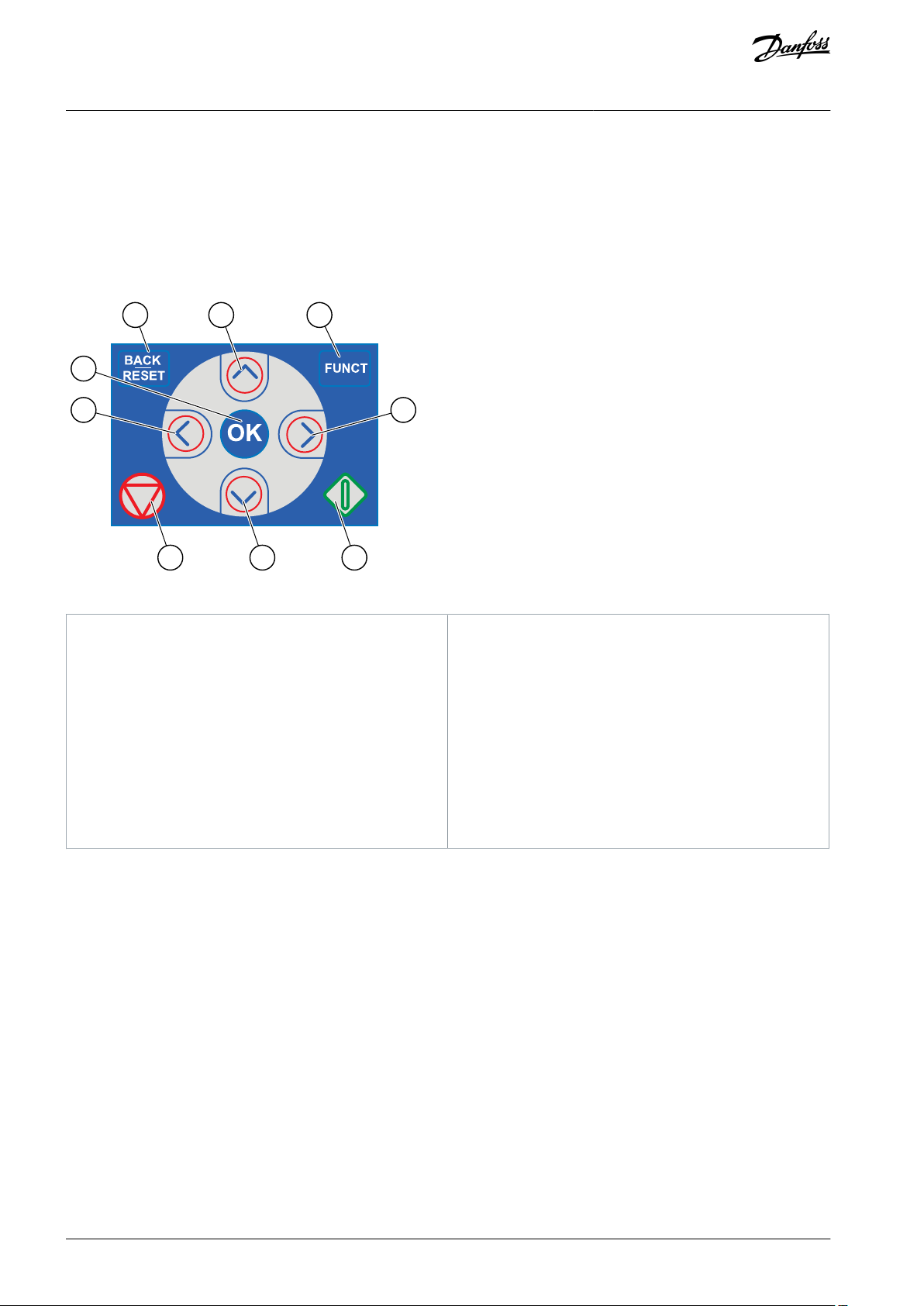
A
The [BACK/RESET] button. Use it to move back in the
menu, exit the Edit mode, reset a fault.
B
The arrow button UP. Use it to scroll up the menu
and to increase a value.
C
The [FUNCT] button. Use it to change the rotation
direction of the motor, access the control page, and
change the control place.
D
The arrow button RIGHT.
E
The START button.
F
The arrow button DOWN. Use it to scroll the menu
down and to decrease a value.
G
The STOP button.
H
The arrow button LEFT. Use it to move the cursor
left.
I
The [OK] button. Use it to go into an active level or
item, or to accept a selection.
VACON® 100 FLOW
Application Guide
User Interfaces
2 User Interfaces
2.1 Description of the Control Panel
2.1.1 Control Panel and the Keypad
The control panel is the interface between the AC drive and the user. With the control panel, it is possible to control the speed of a
motor and monitor the status of the AC drive. It is also possible to set the parameters of the AC drive.
Illustration 2: Buttons of the VACON® 100 Keypad
2.1.2 Displays of the Control Panel
There are 2 display types: the graphical display and the text display. The control panel always has the same keypad and buttons.
The display shows this data.
•
The status of the motor and the drive.
•
Faults in the motor and in the drive.
•
Your location in the menu structure.
If the text in the text display is too long for the display, the text scrolls to show the full text string. Some functions are only available
in the graphical display.
AB298035655957en-000101 / DPD0108314 | Danfoss A/S © 2021.05
STOP
READY
I/O
Main Menu
A
B C D E
F
H
G
Quick Setup
( 17 )
Monitor
( 5 )
Parameters
( 12 )
M1ID:
e30bu013.10
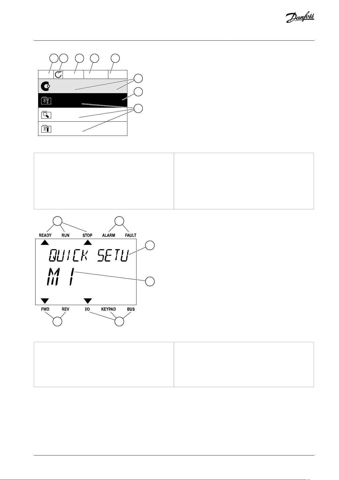
A
The first status field: STOP/RUN
B
The rotation direction of the motor
C
The second status field: READY/NOT READY/FAULT
D
The alarm field: ALARM/-
E
The control place field: PC/I/O/KEYPAD/ FIELDBUS
F
The location field: the ID number of the parameter
and the current location in the menu
G
An activated group or item
H
The number of items in the group in question
A B
F
C
D
E
e30bu014.10
A
The indicators of status
B
The indicators of alarm and fault
C
The name of the group or item of the current locationDThe current location in the menu
E
The indicators of the control place
F
The indicators of the rotation direction
VACON® 100 FLOW
Application Guide
Illustration 3: Graphical Display of the Control Panel
User Interfaces
Illustration 4: Text Display of the Control Panel
2.2 Menu Structure
The data of the AC drive is in menus and submenus. To move between the menus, use the arrow buttons Up and Down in the
keypad. To go into a group or an item, push the [OK] button. To go back to the previous level, push the [BACK/RESET] button.
On the display, current location in the menu shows, for example M3.2.1. The display also shows the name of the group or item in the
current location.
AB298035655957en-000101 / DPD01083 | 15Danfoss A/S © 2021.05

Menu
Function
M1 Quick setup
Wizards (Content depends on P1.2 Application.)
M2 Monitor
Multimonitor
Trend curve
Basic
I/O
Temperature inputs
Extras/Advanced
Timer functions
PID controller
External PID controller
Multi-pump
Maintenance counters
Fieldbus data
Drive customizer
Condition-based monitoring
M3 Parameters
Motor settings
Start/Stop setup
References
Ramps and brakes
I/O Configuration
Fieldbus data
Prohibit frequencies
Supervisions
Protections
Automatic reset
Application settings
Timer functions
PID controller
External PID controller
Multi-Pump
Maintenance counters
Fire mode
VACON® 100 FLOW
Application Guide
Table 2: Menu Structure
User Interfaces
AB298035655957en-000101 / DPD0108316 | Danfoss A/S © 2021.05

Menu
Function
Motor preheat
Drive customizer
Pump control
Advanced harmonic filter
Condition-based monitoring
M4 Diagnostics
Active faults
Reset faults
Fault history
Total counters
Trip counters
Software info
Drive info
Unit status
M5 I/O and Hardware
Basic I/O
Slot C
Slot D
Slot E
Real-time clock
Power unit settings
Keypad
RS485
Ethernet
Fieldbus general
M6 User settings
Language selections
Parameter back-up
Drive name
Parameter compare
Licenses
M7 Favourites
See 9.2.1 Using the Favourites Menu.
M8 User levels
See 9.3.1 Using the User Levels Menu.
VACON® 100 FLOW
Application Guide
User Interfaces
AB298035655957en-000101 / DPD01083 | 17Danfoss A/S © 2021.05
STOP
READY
I/O
Rem Control Place
M3.2.1
ID:
Edit
Help
Add to favourites
e30bu017.10
STOP
READY
I/O
Rem Control Place
M3.2.1ID:
FieldbusCTRL
I/O Control
e30bu018.10
STOP
READY
I/O
MinFreqReference
P3.3.1.1
ID:101
0.00 Hz
Min: 0.00Hz
Max: 50.00Hz
e30bu020.10
VACON® 100 FLOW
Application Guide
2.3 Graphical Display
2.3.1 Editing the Text Values
This topic gives instructions on how to edit the text values on the graphical display.
Procedure
1.
Find the parameter with the arrow buttons.
2.
To go to the Edit mode, push the [OK] button 2 times or push the arrow button Right.
3.
To set a new value, push the arrow buttons Up and Down.
User Interfaces
4.
To accept the change, push the [OK] button. To ignore the change, use the [BACK/RESET] button.
2.3.2 Editing the Numerical Values
This topic gives instructions on how to edit the numerical values on the graphical display.
Procedure
1.
Find the parameter with the arrow buttons.
2.
To go to the Edit mode, push the [OK] button 2 times or push the arrow button Right.
Move from digit to digit with the arrow buttons Left and Right. Change the digits with the arrow buttons Up and Down.
3.
4.
To accept the change, push the [OK] button. To ignore the change, use the [BACK/RESET] button.
AB298035655957en-000101 / DPD0108318 | Danfoss A/S © 2021.05
STOP
READY
I/O
P3.12.1.3ID:1466
Interval 1
00:00:00
00:00:00
ON Time
OFF Time
Days
0
A
e30bu023.10
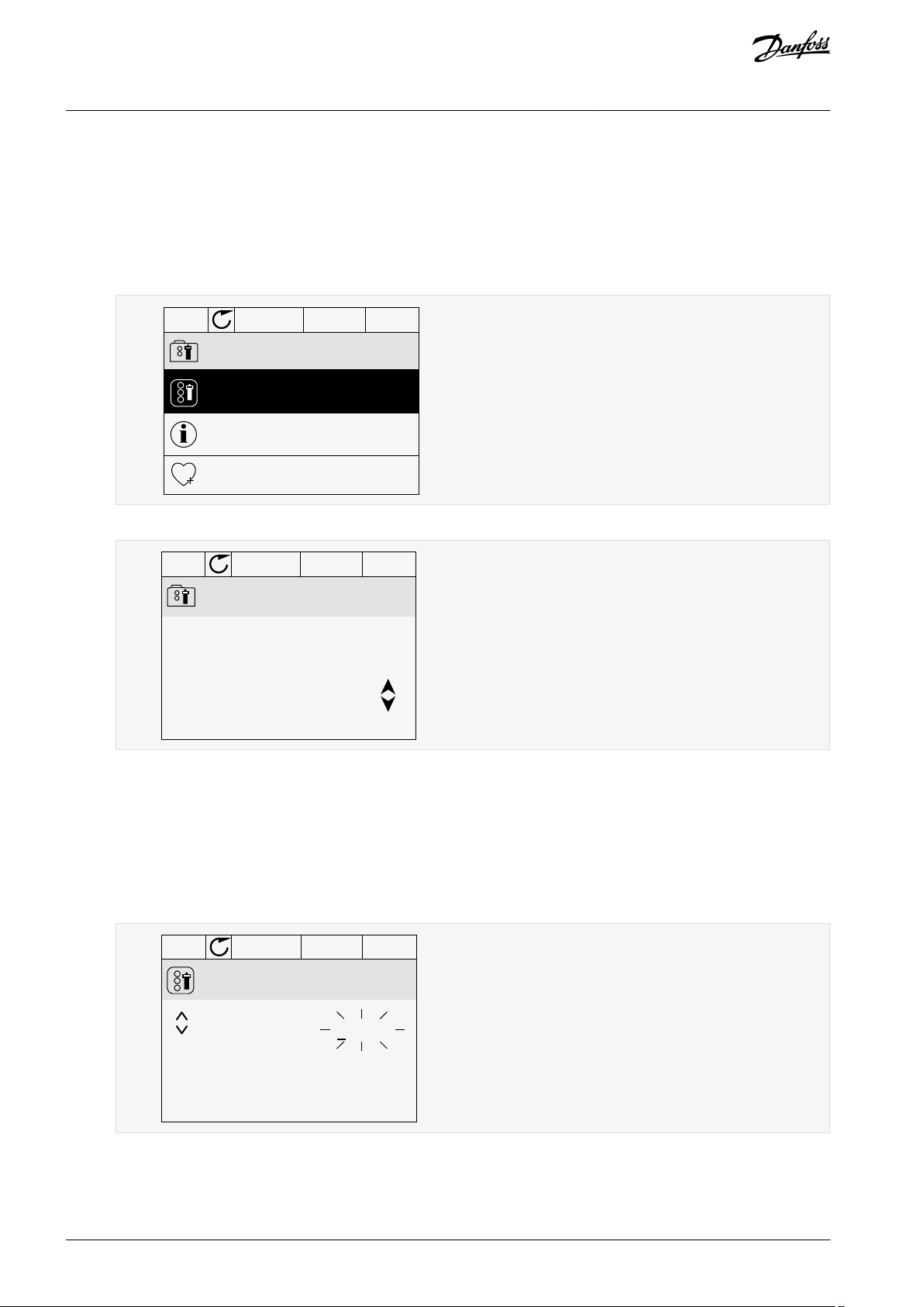
A
The symbol of the checkbox selection
STOP
READY
I/O
M 3.12.1.3.1
ID:
Days
Monday
Tuesday
Wednesday
Thursday
Friday
Sunday
e30bu025.10
VACON® 100 FLOW
Application Guide
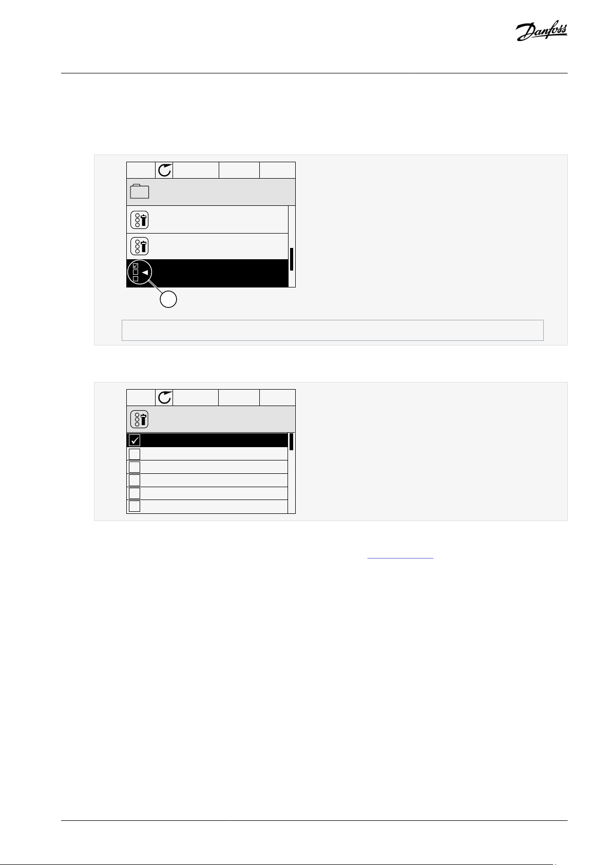
2.3.3 Selecting More than 1 Value
With some parameters, more than 1 value can be selected. Select a checkbox at each necessary value.
Procedure
1.
Find the parameter. There is a symbol on the display when a checkbox selection is possible.
2.
To move in the list of values, use the arrow buttons Up and Down.
3.
To add a value into your selection, select the box that is next to it with the arrow button Right.
User Interfaces
2.3.4 Resetting a Fault
To reset a fault, use the [BACK/RESET] button or the parameter Reset Faults. See 7.1.2 Reset Faults.
2.3.5 [FUNCT] Button
The [FUNCT] button can be used for 4 functions.
•
To have access to the Control page.
•
To change easily between the Local and Remote control places.
•
To change the rotation direction.
•
To edit quickly a parameter value.
2.3.5.1 Different Control Places
The selection of the control place determines from where the AC drive takes the start and stop commands. All the control places
have a parameter for the selection of the frequency reference source. The Local control place is always Keypad. The Remote control
place is I/O or Fieldbus. The status bar of the display shows the current control place.
It is possible to use I/O A, I/O B, and Fieldbus as Remote control places. I/O A and Fieldbus have the lowest priority. Select them with
P3.2.1 (Remote Control Place). I/O B can bypass the Remote control places I/O A and Fieldbus with a digital input. Select the digital
input with parameter P3.5.1.7 (I/O B Control Force).
Keypad is always used as a control place when the control place is Local. Local control has higher priority than Remote control. For
example, if parameter P3.5.1.7 bypasses the control place with a digital input, and Local is selected in Remote control, Keypad becomes the control place. Use the [FUNCT] button or P3.2.2 Local/Remote to change between the Local and Remote control.
AB298035655957en-000101 / DPD01083 | 19Danfoss A/S © 2021.05
STOP
READY Keypad
ID:1805
Choose action
Control page
Change direction
Local/Remote
e30bu027.10
STOP
READY Keypad
ID:211
Local/Remote
Remote
Local
e30bu028.10
VACON® 100 FLOW
Application Guide
2.3.5.2 Changing the Control Place
This topic gives instructions on how to change the control place on the control panel.
Procedure
1.
Anywhere in the menu structure, push the [FUNCT] button.
2.
To select Local/Remote, use the arrow buttons Up and Down. Push the [OK] button.
3.
To select Local or Remote, use the arrow buttons Up and Down again. To accept the selection, push the [OK] button.
User Interfaces
4.
If Remote control place is changed to Local, that is, Keypad, give a keypad reference.
After the selection, the display goes back into the same location where it was when the [FUNCT] button was push-
ed.
2.3.5.3 Going into the Control Page
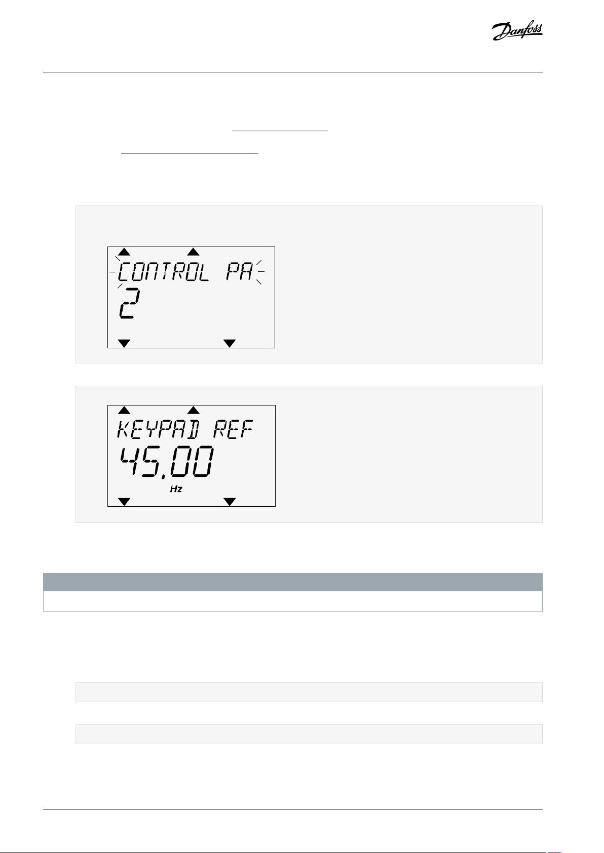
It is easy to monitor the most important values in the Control page.
See more information about Keypad Reference in
display shows the frequency reference, which cannot be edited. The other values on the page are Multimonitor values. These values
can be selected (see 5.2.1 Changing the Items to Monitor).
Procedure
1.
Anywhere in the menu structure, push the [FUNCT] button.
2.
To select the Control page, push the arrow buttons Up and Down. Go in with the [OK] button.
The Control page opens.
With the Local control place and the keypad reference selected, P3.3.1.8 Keypad Reference can be set with the [OK] button.
3.
6.3 Group 3.3: References. If other control places or reference values are used, the
AB298035655957en-000101 / DPD0108320 | Danfoss A/S © 2021.05
STOP
READY Keypad
ID: 168
Keypad Reference
0.00Hz
Output Frequency
Motor Current
Motor Torque
Motor Power
0.00Hz
0.00A
0.00%
0.00%
e30bg671.10
RUN
READY Keypad
ID:1805
Choose action
Forward
Reverse
e30bg672.10
STOP
READY I/O
ID:
M1
Main Menu
Monitor
( 7 )
Parameters
( 15 )
Diagnostics
( 6 )
e30bg673.10
VACON® 100 FLOW
Application Guide
4.
To change the digits in the value, push the arrow buttons Up and Down. Accept the change with the [OK] button.
2.3.5.4 Changing the Rotation Direction
The rotation direction of the motor can be changed quickly with the [FUNCT] button.
N O T I C E
The command Change direction is available in the menu only if the current control place is Local.
Procedure
1.
Anywhere in the menu structure, push the [FUNCT] button.
2.
To select Change direction, push the arrow buttons Up and Down. Push the [OK] button.
3.
Select a new rotation direction.
User Interfaces
The current rotation direction blinks.
4.
Push the [OK] button.
The rotation direction changes immediately. The arrow indication in the status field of the display changes.
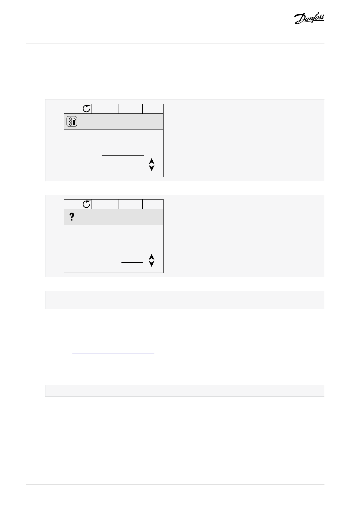
2.3.5.5 Using the Quick Edit Function
With the Quick Edit function, a parameter can be accessed quickly by typing the ID number of the parameter.
Procedure
1.
Anywhere in the menu structure, push the [FUNCT] button.
AB298035655957en-000101 / DPD01083 | 21Danfoss A/S © 2021.05
STOP
READY Keypad
ID: M6.5
User settings
Language selection
English
Parameter backup
( 7 )
Drive name
Drive
e30bg674.10
STOP
READY Keypad
ID: M6.5.1
Parameter backup
Restore factory defaults
Save to keypad
Restore from keypad
e30bg675.10
VACON® 100 FLOW
Application Guide
2.
Push the arrow buttons Up and Down to select Quick Edit and accept with the [OK] button.
3.
Write the ID number of a parameter or monitoring value. Push [OK].
The display shows the parameter value in the edit mode and the monitoring value in the monitoring mode.
User Interfaces
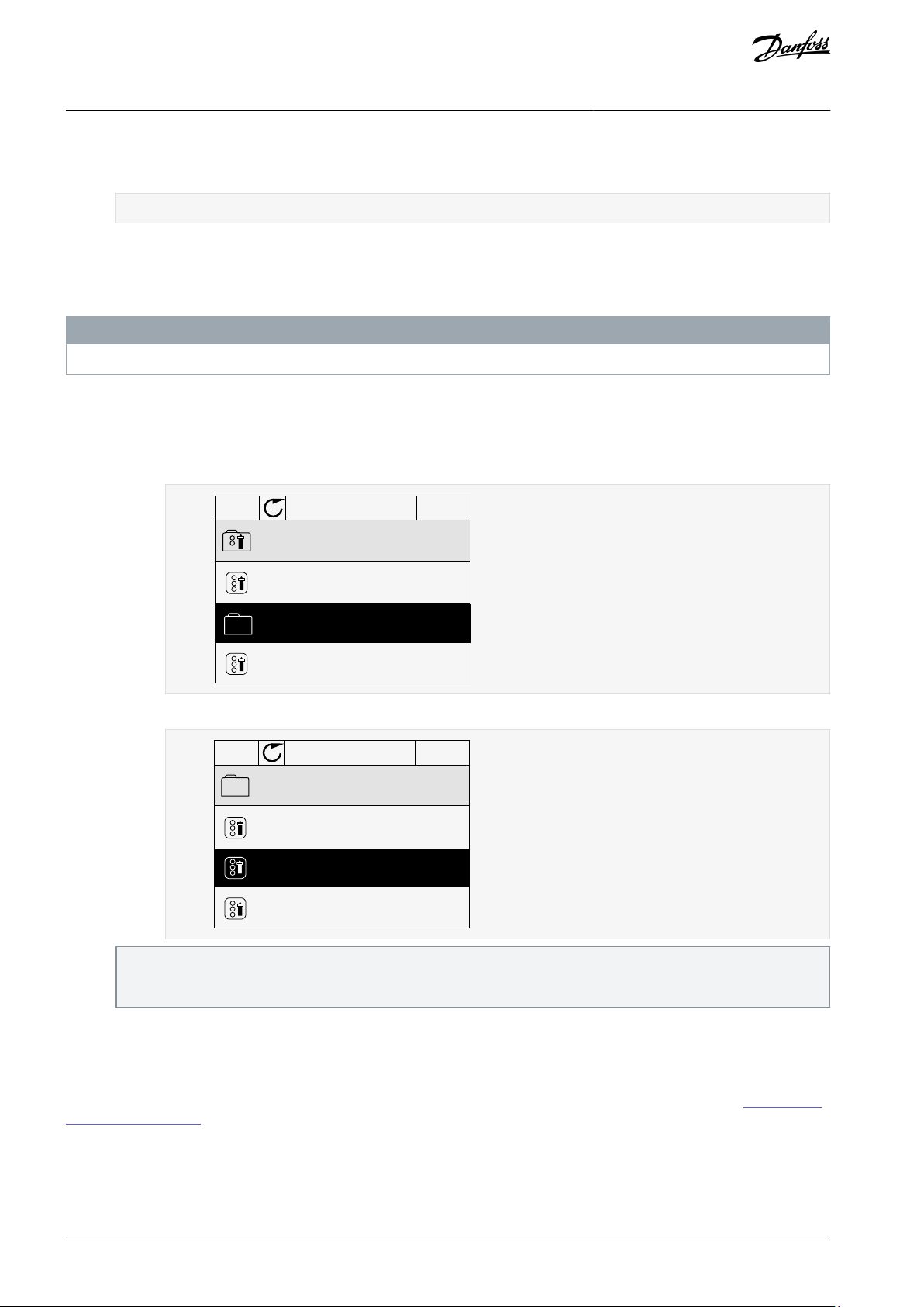
2.3.6 Copying the Parameters of an AC Drive
Use this function to copy parameters from a drive to another. Before downloading parameters from the control panel to the drive,
stop the drive.
N O T I C E
This function is available only in the graphical display.
Procedure
1.
Save the parameters to the control panel.
a.
Go into the User settings menu.
b.
Go into the Parameter backup submenu.
The command Restore factory defaults brings back the parameter settings that were made at the factory. Use the command Save to keypad to copy all the parameters to the control panel. The command Restore from keypad copies all the
parameters from the control panel to the drive.
2.
Detach the control panel and connect it to another drive.
3.
Download the parameters to the new drive with the command Restore from keypad.
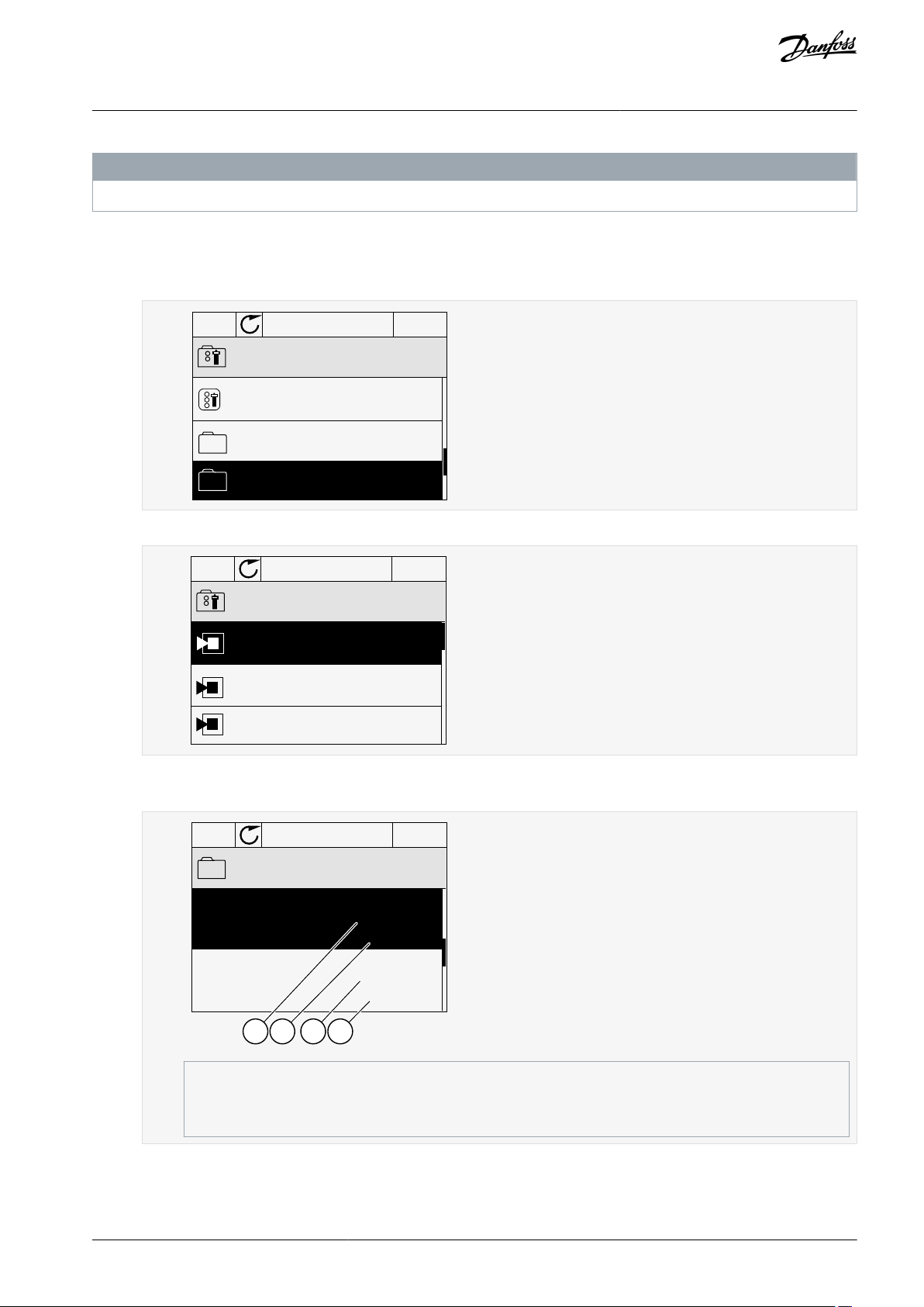
2.3.7 Comparing the Parameters
Use this function to compare the current parameter set with one of these 4 sets. See more about these parameters in
ter Back-up Parameters.
•
Set 1 (P6.5.4 Save to Set 1)
•
Set 2 (P6.5.6 Save to Set 2)
•
Defaults (P6.5.1 Restore Factory Defaults)
•
Keypad set (P6.5.2 Save to Keypad)
c.
Use the arrow buttons Up and Down to select a function. Accept the selection with the [OK] button.
AB298035655957en-000101 / DPD0108322 | Danfoss A/S © 2021.05
9.1.2 Parame-
STOP
READY I/O
ID: M6.6
User Settings
Language Selection
Parameter Backup
Parameter Compare
English
(4)
(7)
e30bg676.10
STOP
READY I/O
ID:
B6.6.1
Parameter Compare
Active set-Set 1
Active set-Set 2
Active set-Defaults
e30bg677.10
STOP
READY I/O
ID:113
Active set-Set 1
Motor Nom Currnt
Motor Cos Phi
0.56A
1.90A
0.68
1.74
A B C D
e30bg678.10
A
The current value
B
The value of the other set
C
The current value
D
The value of the other set
VACON® 100 FLOW
Application Guide
User Interfaces
N O T I C E
If the parameter set with which the current set is compared was not saved, the display shows the text Comparing failed.
Procedure
1.
Go into the User settings menu.
2.
Go into the Parameter Compare function.
3.
Select the pair of sets. Push [OK] to accept the selection.
4.
Select Active and push [OK].
5.
Examine the comparing between the current values and the values of the other set.
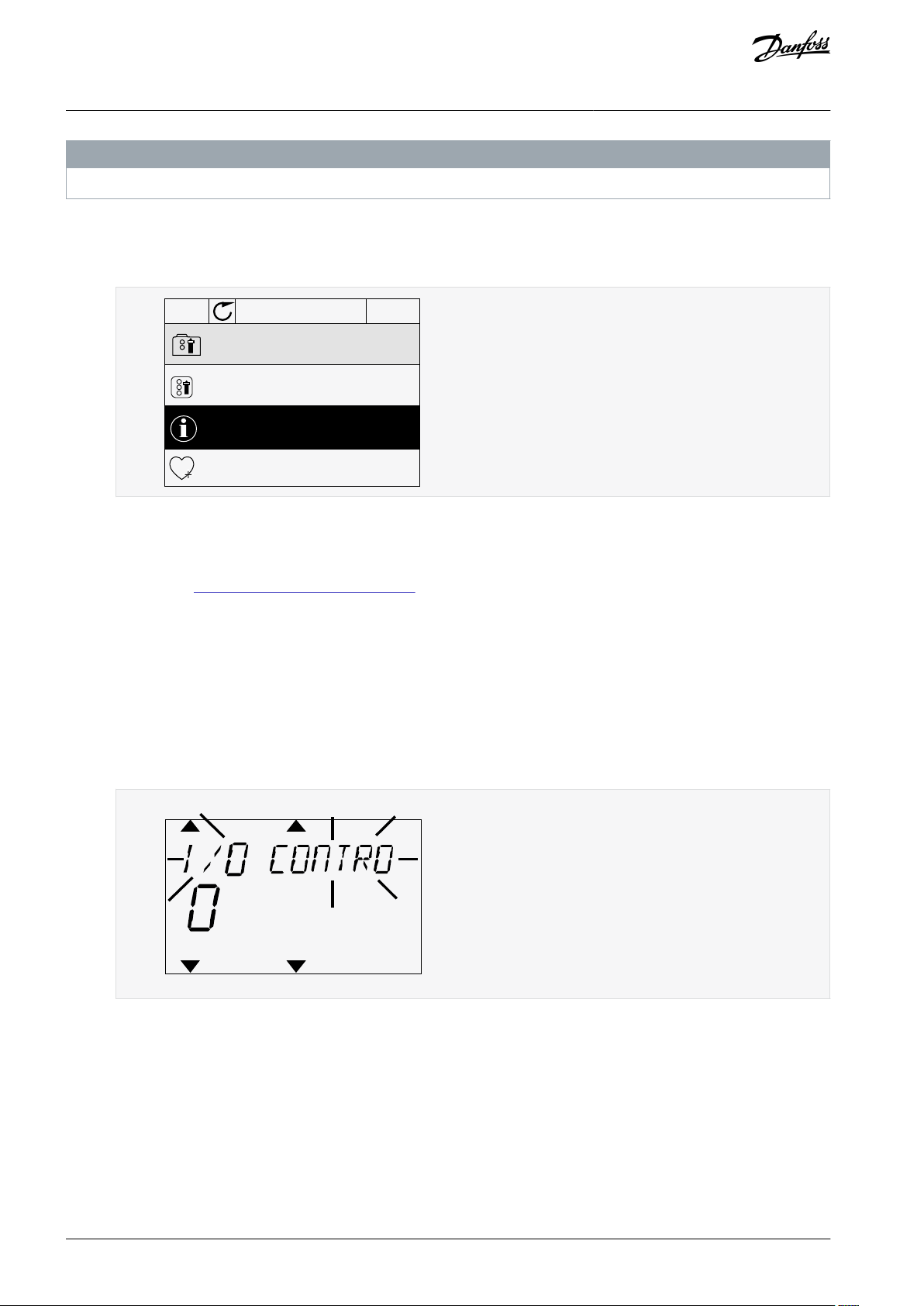
2.3.8 Reading Help Texts
The graphical display can show help texts on many topics. All the parameters have a help text. The help texts are also available for
the faults, alarms, and the start-up wizard.
AB298035655957en-000101 / DPD01083 | 23Danfoss A/S © 2021.05
STOP
READY I/O
ID:403 M3.5.1.1
Ctrl signal 1 A
Edit
Help
Add to favourites
e30bg679.10
READY
FAULT
ALARM
STOP
RUN
KEYPAD
I/O
REV
FWD
BUS
e30bg680.10
VACON® 100 FLOW
Application Guide
The help texts are always in English.
Procedure
1.
Find the item to read.
2.
Use the arrow buttons Up and Down to select Help.
3.
To open the help text, push the [OK] button.
User Interfaces
N O T I C E
2.3.9 Using the Favourites Menu
If the same items are used frequently, add them into Favourites. Collect a set of parameters or monitoring signals from all the control panel menus. See 9.2.2 Adding an Item to the Favourites.
2.4 Text Display
2.4.1 Editing the Text Values
This topic gives instructions on how to edit text values on the text display.
Procedure
1.
Find the parameter with the arrow buttons.
2.
To go to the Edit mode, push the [OK] button.
3.
To set a new value, push the arrow buttons Up and Down.
4.
Accept the change with the [OK] button. To ignore the change, use the [BACK/RESET] button.
2.4.2 Editing the Numerical Values
This topic gives instructions on how to edit the numerical values on the text display.
Procedure
1.
Find the parameter with the arrow buttons.
2.
Go to the Edit mode.
3.
Move from digit to digit with the arrow buttons Left and Right. Change the digits with the arrow buttons Up and Down.
4.
Accept the change with the [OK] button. To ignore the change, use the [BACK/RESET] button.
AB298035655957en-000101 / DPD0108324 | Danfoss A/S © 2021.05
READY
FAULT
ALARM
STOP
RUN
KEYPAD
I/O
REV
FWD
BUS
e30bg681.10
READY
FAULT
ALARM
STOP
RUN
KEYPAD
I/O
REV
FWD
BUS
e30bg682.10
VACON® 100 FLOW
Application Guide
User Interfaces
2.4.3 Resetting a Fault
To reset a fault, use the [BACK/RESET] button or the parameter Reset Faults. See 7.1.2 Reset Faults.
2.4.4 [FUNCT] Button
The [FUNCT] button can be used for 4 functions.
•
To have access to the Control page.
•
To change easily between the Local and Remote control places.
•
To change the rotation direction.
•
To edit quickly a parameter value.
2.4.4.1 Different Control Places
The selection of the control place determines from where the AC drive takes the start and stop commands. All the control places
have a parameter for the selection of the frequency reference source. The Local control place is always Keypad. The Remote control
place is I/O or Fieldbus. The status bar of the display shows the current control place.
It is possible to use I/O A, I/O B, and Fieldbus as Remote control places. I/O A and Fieldbus have the lowest priority. Select them with
P3.2.1 (Remote Control Place). I/O B can bypass the Remote control places I/O A and Fieldbus with a digital input. Select the digital
input with parameter P3.5.1.7 (I/O B Control Force).
Keypad is always used as a control place when the control place is Local. Local control has higher priority than Remote control. For
example, if parameter P3.5.1.7 bypasses the control place with a digital input, and Local is selected in Remote control, Keypad becomes the control place. Use the [FUNCT] button or P3.2.2 Local/Remote to change between the Local and Remote control.
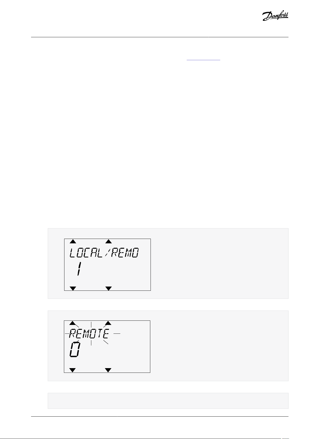
2.4.4.2 Changing the Control Place
This topic gives instructions on how to change the control place on the control panel.
Procedure
Anywhere in the menu structure, push the [FUNCT] button.
1.
2.
To select Local/Remote, use the arrow buttons Up and Down. Push the [OK] button.
3.
To select Local or Remote, use the arrow buttons Up and Down again. To accept the selection, push the [OK] button.
4.
If Remote control place is changed to Local, that is, the keypad, give a keypad reference.
After the selection, the display goes back into the same location where it was when the [FUNCT] button was pushed.
AB298035655957en-000101 / DPD01083 | 25Danfoss A/S © 2021.05
READY
FAULT
ALARM
STOP
RUN
KEYPAD
I/O
REV
FWD
BUS
e30bg683.10
READY
FAULT
ALARM
STOP
RUN
KEYPAD
I/O
REV
FWD
BUS
e30bg684.10
VACON® 100 FLOW
Application Guide
User Interfaces
2.4.4.3 Going into the Control Page
It is easy to monitor the most important values in the Control page.
See more information about Keypad Reference in 6.3 Group 3.3: References. If other control places or reference values are used, the
display shows the frequency reference that cannot be edited. The other values on the page are Multimonitor values. These values
can be selected (see
Procedure
1.
Anywhere in the menu structure, push the [FUNCT] button.
2.
To select the Control page, push the arrow buttons Up and Down. Go in with the [OK] button.
5.2.1 Changing the Items to Monitor).
The Control page opens.
3.
If the Local control place and the keypad reference are used, P3.3.1.8 Keypad Reference can be set with the [OK] button.
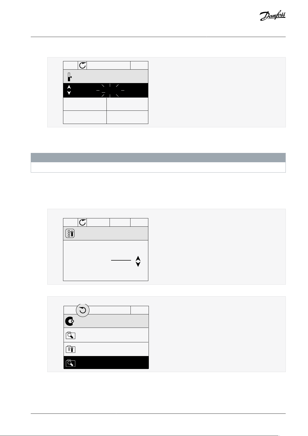
2.4.4.4 Changing the Rotation Direction
The rotation direction of the motor can be changed quickly with the [FUNCT] button.
N O T I C E
The command Change direction is available in the menu only if the current control place is Local.
Procedure
1.
Anywhere in the menu structure, push the [FUNCT] button.
2.
To select Change direction, push the arrow buttons Up and Down. Push the [OK] button.
3.
Select a new rotation direction.
The current rotation direction blinks.
4.
Push the [OK] button.
The rotation direction changes immediately. The arrow indication in the status field of the display changes.
2.4.4.5 Using the Quick Edit Function
With the Quick Edit function, a parameter can be accessed quickly by typing the ID number of the parameter.
Procedure
AB298035655957en-000101 / DPD0108326 | Danfoss A/S © 2021.05
e30bg685.10
VACON® 100 FLOW
Application Guide
1.
Anywhere in the menu structure, push the [FUNCT] button.
2.
Push the arrow buttons Up and Down to select Quick Edit and accept with the [OK] button.
3.
Write the ID number of a parameter or monitoring value. Push [OK].
The display shows the parameter value in the edit mode and the monitoring value in the monitoring mode.
User Interfaces
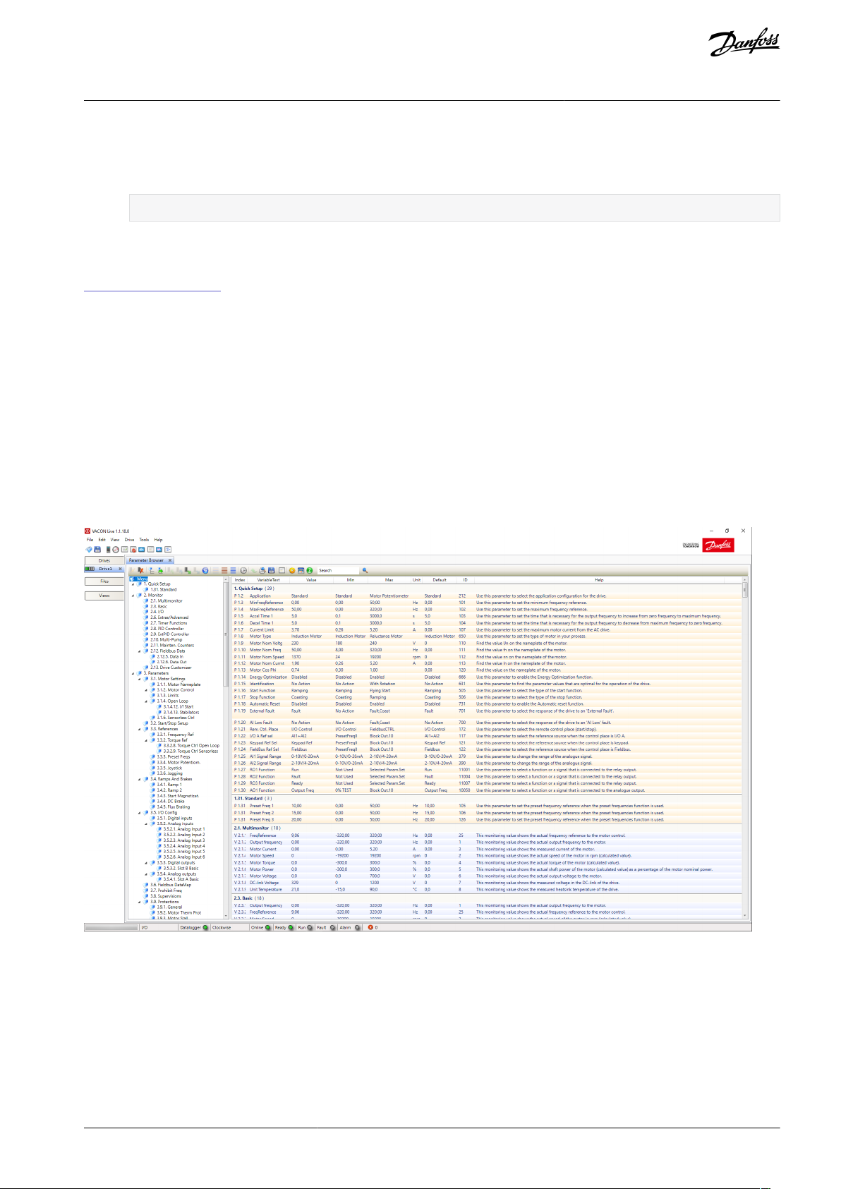
2.5 VACON® Live PC Tool
VACON® Live is a PC tool for commissioning and maintenance of the VACON® AC drives. VACON® Live can be downloaded from
https://www.danfoss.com.
The VACON® Live PC tool includes these functions.
•
Parameterization, monitoring, drive info, data logger, and so on.
•
The software download tool VACON® Loader
Serial communication and Ethernet support
•
Windows XP, Vista, 7, 8, and 10 support
•
17 languages: English, German, Spanish, Finnish, French, Italian, Russian, Swedish, Chinese, Czech, Danish, Dutch, Polish, Portu-
•
guese, Romanian, Slovak and Turkish
Make the connection between the AC drive and the PC tool with the VACON® serial communication cable. The serial communication drivers are installed automatically during the installation of VACON® Live. After the cable is installed, VACON® Live finds the
connected drive automatically.
See more on how to use VACON® Live in the help menu of the program.
Illustration 5: The VACON® Live PC Tool
AB298035655957en-000101 / DPD01083 | 27Danfoss A/S © 2021.05

VACON® 100 FLOW
Application Guide
Applications
3 Applications
3.1 Using the Applications
Use the parameter P1.2 (Application) to select an application for the drive. Immediately when the parameter P1.2 changes, parameter groups get their preset values.
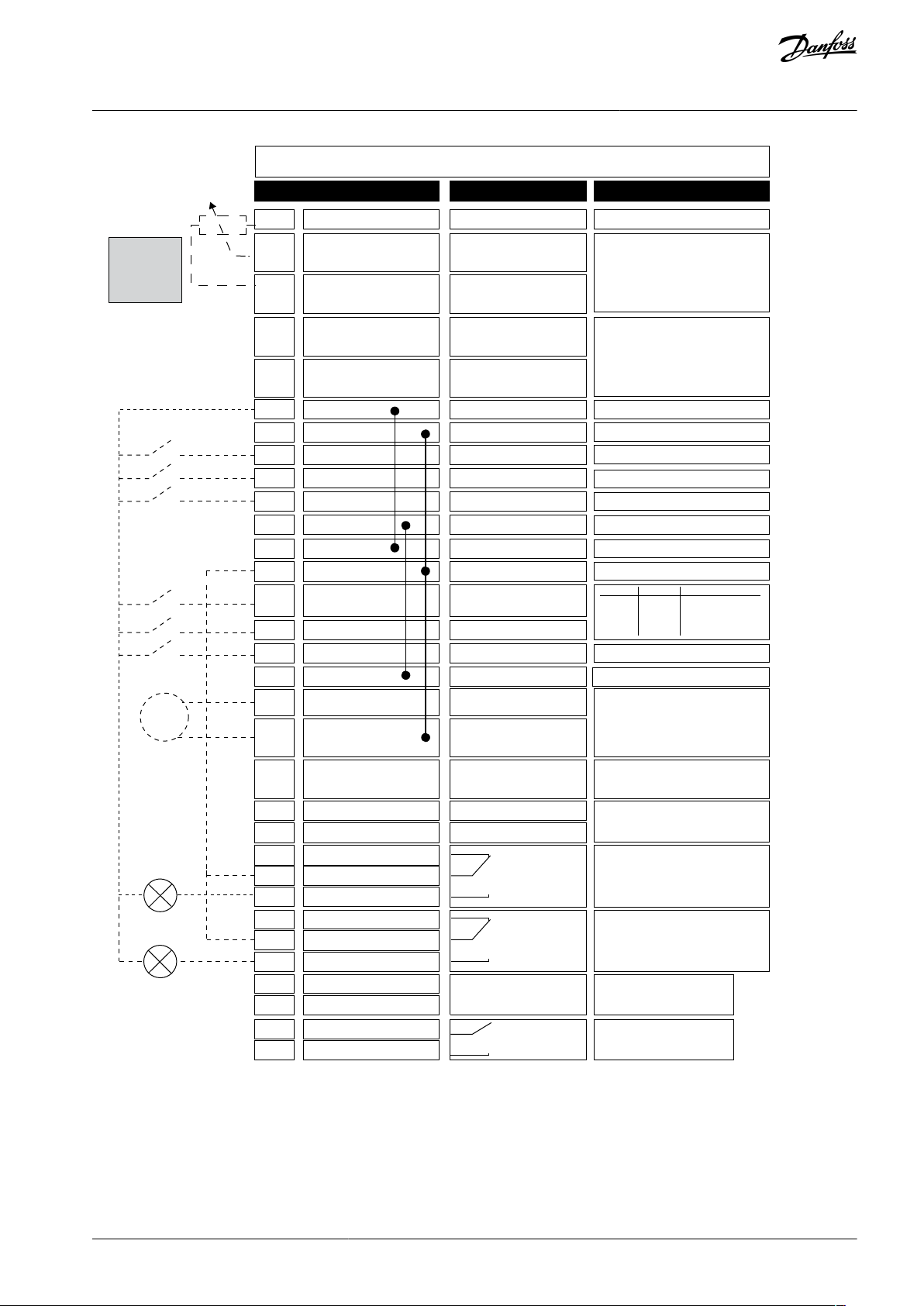
3.2 Standard and HVAC Applications
Use the Standard and HVAC applications to control pumps or fans, for example.
It is possible to control the drive from the control panel (keypad), Fieldbus, or I/O terminal.
When the drive is controlled with the I/O terminal, the frequency reference signal is connected to AI1 (0…10 V) or AI2 (4…20 mA).
The connection depends the type of the signal. There are also 3 preset frequency references available. The preset frequency references can be activated with DI4 and DI5. The start/stop signals of the drive are connected to DI1 (start forward) and DI2 (start reverse).
It is possible to configure all the drive outputs freely in all the applications. There is 1 analog output (Output Frequency) and 3 relay
outputs (Run, Fault, Ready) available on the basic I/O board.
AB298035655957en-000101 / DPD0108328 | Danfoss A/S © 2021.05
DI4
DI5
**)
*)
Modbus RTU,
N2, BACnet
1
6
2
3
4
5
18
19
30
12
7
13
8
9
10
14
15
16
21
22
23
11
17
A
B
24
25
26
32
33
28
29
e30bg590.10
mA
FAULT
RUN
RUN
AO1-
+24Vin
24Vout
GND
GND
DI1
DI2
DI3
DI4
DI5
DI6
R
O1/1 NC
R
O1/2 CM
R
O1/3 NO
CM
CM
RS485
RS485
R
O2/1 NC
R
O2/2 CM
R
O2/3 NO
R
O3/2 CM
R
O3/3 NO
Standard I/O board
Terminal Signal Description
+10 Vref
AI1+
AI1-
AI2+
AI2-
24Vout
Reference output
Analog input 1 +
Analog input 1 -
Analog input 2 +
Analog input 2 -
24 V auxiliary voltage
I/O ground
Digital input 1
Digital input 2
Digital input 3
Digital input 4
Digital input 5
Digital input 6
Common for DI1-DI6
Common for DI1-DI6
24 V auxiliary voltage
I/O ground
Analog output 1 +
Analog output 1 -
24V auxiliary
input voltage
Output
frequency
0...20 mA)
READY
Serial bus, negative
Serial bus, positive
Relay output 1
Relay output 2
Relay output 3
FAULT
Fault reset
AO1+
Frequency reference
(default 0...10 V)
Frequency reference
(Default 4...20 mA)
Start forward
Start reverse
External fault
Freq. ref.
Open
Closed
Open
Closed
Open
Open
Closed
Closed
Analog input 1
Preset Freq. 1
Preset Freq. 2
Preset Freq. 3
Reference-
potentiome-
ter
1...10 kΩ
TI1+
TI1-
Thermistor input
VACON® 100 FLOW
Application Guide
Applications
Illustration 6: The Default Control Connections of the Standard and HVAC Applications
*) Available only in VACON® 100 X. **) For the DIP switch configurations in VACON® 100 X, see the VACON® 100 X Installation manual.
AB298035655957en-000101 / DPD01083 | 29Danfoss A/S © 2021.05
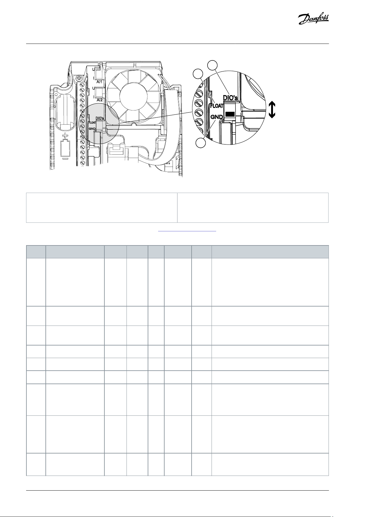
A
B
C
e30bg589.10
A
Digital input DIP switch
B
Floating
C
Connected to GND (Default)
Index
Parameter
Min
Max
Unit
Default
ID
Description
1.2
Application
040
212
0 = Standard
1 = HVAC
2 = PID Control
3 = Multi-pump (single drive)
4 = Multi-pump (multidrive)
1.3
Minimum Frequency
Reference
0.00
P1.4Hz0.0
101
1.4
Maximum Frequency
Reference
P1.3
320.0
Hz
50.0/60.0
102
1.5
Acceleration Time 1
0.1
3000.0
s
5.0
103
1.6
Deceleration Time 1
0.1
3000.0
s
5.0
104
1.7
Motor Current Limit
IH*0.1
ISA
Varies
107
1.8
Motor Type
020
650
0 = Induction Motor
1 = Permanent Magnet Motor
2 = Reluctance Motor
1.9
Motor Nominal Voltage
Varies
Varies
V
Varies
110
Find this value Un on the nameplate of the motor.
NOTE! Find out if the motor connection is Delta
or Star.
1.10
Motor Nominal Frequency
8.0
320.0
Hz
50/60
111
Find this value fn on the nameplate of the motor.
VACON® 100 FLOW
Application Guide
Illustration 7: The DIP Switch
Applications
See information on the Startup, and Fire mode wizards in 4.2.1 Wizards in Menu 1.1.
Table 3: M1 Quick Setup
AB298035655957en-000101 / DPD0108330 | Danfoss A/S © 2021.05

Index
Parameter
Min
Max
Unit
Default
ID
Description
1.11
Motor Nominal Speed
24
19200
RPM
Varies
112
Find this value nn on the nameplate of the motor.
1.12
Motor Nominal Current
IH * 0.1
IH * 2
A
Varies
113
Find this value In on the nameplate of the motor.
1.13
Motor Cos Phi (Power
Factor)
0.30
1.00
Varies
120
Find this value on the nameplate of the motor.
1.14
Energy Optimization
010
666
0 = Disabled
1 = Enabled
1.15
Identification
020
631
0 = No action
1 = At standstill
2 = With rotation
1.16
Start Function
010
505
0 = Ramping
1 = Flying Start
1.17
Stop Function
010
506
0 = Coasting
1 = Ramping
1.18
Automatic Reset
010
731
0 = Disabled
1 = Enabled
1.19
Response to External
Fault
032
701
0 = No action
1 = Alarm
2 = Fault (Stop according to stop mode)
3 = Fault (Stop by coasting)
1.20
Response to AI Low
Fault
050
700
0 = No action
1 = Alarm
2 = Alarm+preset fault frequency (P3.9.1.13)
3 = Alarm + previous frequency
4 = Fault (Stop according to stop mode)
5 = Fault (Stop by coasting)
1.21
Remote Control Place
010
172
0 = I/O control
1 = Fieldbus control
1.22
I/O Control Reference
A Selection
1205
117
1 = Preset Frequency 0
2 = Keypad reference
3 = Fieldbus
4 = AI1
5 = AI2
6 = AI1+AI2
7 = PID reference
8 = Motor potentiometer
11 = Block Out.1
12 = Block Out.2
13 = Block Out.3
14 = Block Out.4
15 = Block Out.5
VACON® 100 FLOW
Application Guide
Applications
AB298035655957en-000101 / DPD01083 | 31Danfoss A/S © 2021.05

Index
Parameter
Min
Max
Unit
Default
ID
Description
16 = Block Out.6
17 = Block Out.7
18 = Block Out.8
19 = Block Out.9
20 = Block Out.10
1.23
Keypad Control Reference Selection
1201
121
See P1.22.
1.24
Fieldbus Control Reference Selection
1202
122
See P1.22.
1.25
AI1 Signal Range
010
379
0= 0...10 V/0...20 mA
1= 2...10 V/4...20 mA
1.26
AI2 Signal Range
011
390
0= 0...10 V/0...20 mA
1= 2...10 V/4...20 mA
1.27
RO1 Function
0742
11001
See P3.5.3.2.1.
1.28
RO2 Function
0743
11004
See P3.5.3.2.1.
1.29
RO3 Function
0741
11007
See P3.5.3.2.1.
1.30
AO1 Function
0312
10050
See P3.5.4.1.1.
Index
Parameter
Min
Max
Unit
Default
ID
Description
1.31.1
Preset Frequency 1
P1.3
P1.4Hz10.0
105
1.31.2
Preset Frequency 2
P1.3
P1.4Hz15.0
106
1.31.3
Preset Frequency 3
P1.3
P1.4Hz20.0
126
VACON® 100 FLOW
Application Guide
Applications
Table 4: M1.31 Standard/M1.32 HVAC
3.3 PID Control Application
Use the PID control application with processes where the process variable (for example pressure) is controlled through control of
the speed of the motor.
In this application, the internal PID controller of the drive is configured for 1 setpoint and 1 feedback signal.
It is possible to use 2 control places. Make the selection of the control place A or B with DI6. When control place A is active, the start/
stop commands are given by DI1, and the PID controller gives the frequency reference. When control place B is active, start/stop
commands are given by DI4, and AI1 gives the frequency reference.
It is possible to configure all the drive outputs freely in all the applications. There are 1 analog output (Output Frequency) and 3
relay outputs (Run, Fault, Ready) available on the basic I/O board.
AB298035655957en-000101 / DPD0108332 | Danfoss A/S © 2021.05

1
6
2
3
4
5
18
19
30
12
7
13
8
9
10
14
15
16
21
22
23
11
17
A
B
24
25
26
28
29
32
33
Modbus RTU
+
-
*)
**)
TI1-
TI1+
mA
FAULT
RUN
RUN
AO1-/GND
+24 Vin
24 Vout
GND
GND
DI1
DI2
DI3
DI4
DI5
DI6
CM
CM
RS485
RS485
Standard I/O board
Terminal Signal Description
+10Vref
AI1+
AI1-
AI2+
AI2-
24 Vout
Reference output
Analog input 1 +
Analog input 1 -
Analog input 2 +
Analog input 2 -
24 V auxiliary voltage
I/O ground
Digital input 1
Digital input 2
Digital input 3
Digital input 4
Digital input 5
Digital input 6
Common for DI1-DI6
Common for DI1-DI6
24 V auxiliary voltage
I/O ground
Analog output 1 +
Analog output 1 -
24 V auxiliary
input voltage
Output
frequency
0...20 mA)
Serial bus, negative
Serial bus, positive
Relay output 1
Relay output 2
READY
Relay output 3
FAULT
Fault reset
AO1+
Place A: PID setpoint (reference)
Place B: Frequency reference
(default: 0...10 V)
PID feedback
(actual value)
(default: 4...20 mA)
Place A: Start forward
(PID controller)
External fault
Control place A/B selection
Referencepo-
tentiometer
1...10 kΩ
Preset frequency 1
I =
(0)4...20 mA
Actual
value
2-wire
transmitter
Place B: Start forward
(Freq. reference P3.3.1.6)
RO3/3 NO
RO3/2 CM
RO2/3 NO
RO2/2 CM
RO2/1 NC
RO1/1 NC
RO1/2 CM
RO1/3 NO
Thermistor input
e30bi987.10
VACON® 100 FLOW
Application Guide
Applications
Illustration 8: The Default Control Connections of the PID Control Application
*) Available only in VACON® 100 X. **) For the DIP switch configurations in VACON® 100 X, see the VACON® 100 X Installation manual.
AB298035655957en-000101 / DPD01083 | 33Danfoss A/S © 2021.05

A
B
C
e30bg589.10
A
Digital input DIP switch
B
Floating
C
Connected to GND (Default)
Index
Parameter
Min
Max
Unit
Default
ID
Description
1.2
Application
042
212
0 = Standard
1 = HVAC
2 = PID Control
3 = Multi-pump (single drive)
4 = Multi-pump (multidrive)
1.3
Minimum Frequency
Reference
0.00
P1.4Hz0.0
101
1.4
Maximum Frequency
Reference
P1.3
320.0
Hz
50.0/60.0
102
1.5
Acceleration Time 1
0.1
3000.0
s
5.0
103
1.6
Deceleration Time 1
0.1
3000.0
s
5.0
104
1.7
Motor Current Limit
IH*0.1
ISA
Varies
107
1.8
Motor Type
020
650
0 = Induction Motor
1 = Permanent Magnet Motor
2 = Reluctance Motor
1.9
Motor Nominal Voltage
Varies
Varies
V
Varies
110
Find this value Un on the nameplate of the motor.
NOTE! Find out if the motor connection is Delta
or Star.
1.10
Motor Nominal Frequency
8.0
320.0
Hz
50/60
111
Find this value fn on the nameplate of the motor.
VACON® 100 FLOW
Application Guide
Illustration 9: The DIP Switch
Applications
See information on the Startup, and Fire mode wizards in 4.2.1 Wizards in Menu 1.1.
Table 5: M1 Quick Setup
AB298035655957en-000101 / DPD0108334 | Danfoss A/S © 2021.05

Index
Parameter
Min
Max
Unit
Default
ID
Description
1.11
Motor Nominal Speed
24
19200
RPM
Varies
112
Find this value nn on the nameplate of the motor.
1.12
Motor Nominal Current
IH * 0.1
IH * 2
A
Varies
113
Find this value In on the nameplate of the motor.
1.13
Motor Cos Phi (Power
Factor)
0.30
1.00
Varies
120
Find this value on the nameplate of the motor.
1.14
Energy Optimization
010
666
0 = Disabled
1 = Enabled
1.15
Identification
020
631
0 = No action
1 = At standstill
2 = With rotation
1.16
Start Function
010
505
0 = Ramping
1 = Flying Start
1.17
Stop Function
010
506
0 = Coasting
1 = Ramping
1.18
Automatic Reset
010
731
0 = Disabled
1 = Enabled
1.19
Response to External
Fault
032
701
0 = No action
1 = Alarm
2 = Fault (Stop according to stop mode)
3 = Fault (Stop by coasting)
1.20
Response to AI Low
Fault
050
700
0 = No action
1 = Alarm
2 = Alarm+preset fault frequency (P3.9.1.13)
3 = Alarm + previous frequency
4 = Fault (Stop according to stop mode)
5 = Fault (Stop by coasting)
1.21
Remote Control Place
010
172
0 = I/O control
1 = Fieldbus control
1.22
I/O Control Reference
A Selection
1206
117
1 = Preset Frequency 0
2 = Keypad reference
3 = Fieldbus
4 = AI1
5 = AI2
6 = AI1+AI2
7 = PID reference
8 = Motor potentiometer
11 = Block Out.1
12 = Block Out.2
13 = Block Out.3
14 = Block Out.4
15 = Block Out.5
VACON® 100 FLOW
Application Guide
Applications
AB298035655957en-000101 / DPD01083 | 35Danfoss A/S © 2021.05

Index
Parameter
Min
Max
Unit
Default
ID
Description
16 = Block Out.6
17 = Block Out.7
18 = Block Out.8
19 = Block Out.9
20 = Block Out.10
1.23
Keypad Control Reference Selection
1201
121
See P1.22.
1.24
Fieldbus Control Reference Selection
1202
122
See P1.22.
1.25
AI1 Signal Range
010
379
0= 0...10 V/0...20 mA
1= 2...10 V/4...20 mA
1.26
AI2 Signal Range
011
390
0= 0...10 V/0...20 mA
1= 2...10 V/4...20 mA
1.27
RO1 Function
0742
11001
See P3.5.3.2.1.
1.28
RO2 Function
0743
11004
See P3.5.3.2.1.
1.29
RO3 Function
0741
11007
See P3.5.3.2.1.
1.30
AO1 Function
0312
10050
See P3.5.4.1.1.
Index
Parameter
Min
Max
Unit
Default
ID
Description
1.33.1
PID Gain
0.00
100.00
%
100.00
118
1.33.2
PID Integration Time
0.00
600.00
s
1.00
119
1.33.3
PID Derivation Time
0.00
100.00
s
0.00
132
1.33.4
Process Unit Selection
1441
1036
See P3.13.1.4
1.33.5
Process Unit Min
Varies
Varies
Varies
1033
See P3.13.2.6.
1.33.6
Process Unit Max
Varies
Varies
Varies
1034
1.33.7
Feedback 1 Source Selection
0302
334
See P3.13.3.3
1.33.8
Setpoint 1 Source Selection
0321
332
See P3.13.2.6
1.33.9
Keypad Setpoint 1
Varies
Varies
Varies
0
167
1.33.10
SP1 Sleep Frequency Limit
0.0
320.0
Hz
0.0
1016
1.33.11
SP1 Sleep Delay
0
3000s0
1017
0 = Not used
1.33.12
SP1 Wake Up Level
Varies
Varies
Varies
Varies
1018
0 = Not used
1.33.13
Preset Frequency 1
P1.3
P1.4Hz10.0
105
VACON® 100 FLOW
Application Guide
Applications
Table 6: M1.33 PID Control
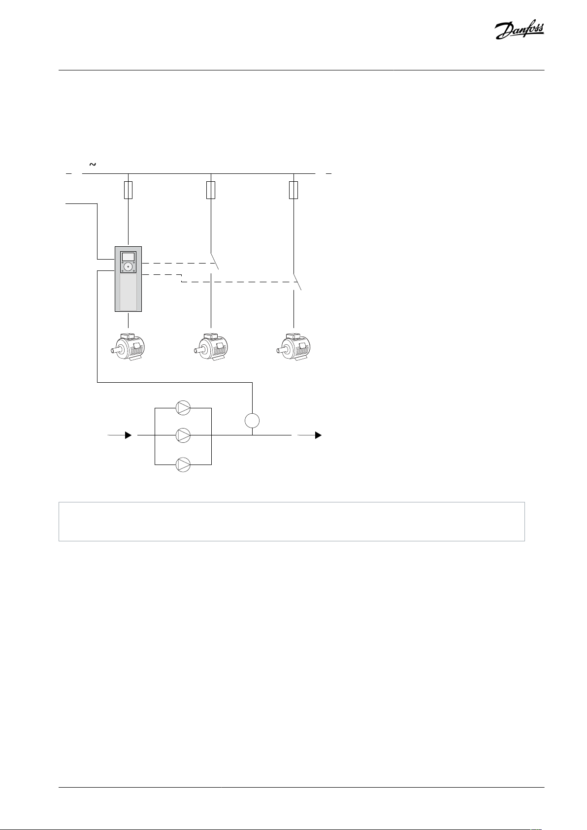
3.4 Multi-pump (Single Drive) Application
Use the Multi-pump (single drive) application in applications, where 1 drive controls a system that has the maximum of 8 parallel
motors, for example, pumps, fans or compressors. By default, Multi-pump (single drive) application is configured for 3 parallel motors.
AB298035655957en-000101 / DPD0108336 | Danfoss A/S © 2021.05
3
B
RO2
RO3
M1
M1
M2
M2
M3
M3
A
e30bi974.10
A
Start / Stop
B
Pressure sensor
VACON® 100 FLOW
Application Guide
Applications
The drive is connected to 1 of the motors, which becomes the regulating motor. The internal PID controller of the drive controls the
speed of the regulating motor and gives control signals by relay outputs to start or stop the auxiliary motors. External contactors
(switch) set the auxiliary motors to the mains.
It is possible to control a process variable, the pressure, for example, by the control of the speed of the regulating motor and by the
number of motors that operate.
Illustration 10: Multi-pump (Single Drive) Configuration
Autochange function (change of start order) makes the wear of the motors in the system more equal. Autochange function monitors the running hours and sets the start order of each motor. The motor that has the lowest running hours starts first and the motor
that has the highest running hours starts last. It is possible to configure the autochange to start based on the autochange interval
time set by the internal real-time clock (an RTC battery needed) of the drive.
It is possible to configure the autochange for all the motors in the system or only the auxiliary motors.
AB298035655957en-000101 / DPD01083 | 37Danfoss A/S © 2021.05

K2 K3
M1 M2 M3
3
e30bi975.10
K1 K2 K2
K1.1
K2.1 K3.1
M1 M2 M3
e30bi976.10
VACON® 100 FLOW
Application Guide
Applications
Illustration 11: Control Diagram with Only the Auxiliary Motors Configured to Autochange
Illustration 12: Control Diagram with All the Motors Configured to Autochange
It is possible to use 2 control places. Make the selection of the control place A or B with DI6. When control place A is active, DI1 gives
the start and stop commands, and the PID controller gives the frequency reference. When control place B is active, DI4 gives the
start and stop commands, and AI1 gives the frequency reference.
It is possible to configure all the drive outputs freely in all the applications. There is 1 analog output (Output Frequency) and 3 relay
outputs (Run, Fault, Ready) available on the basic I/O board.
AB298035655957en-000101 / DPD0108338 | Danfoss A/S © 2021.05

1
6
2
3
4
5
18
19
30
12
7
13
8
9
10
14
15
16
21
22
23
11
17
A
B
24
25
26
28
29
Modbus RTU
*)
32
33
**)
+
-
A1
A1
A1
A2
A2
A2
TI1-
TI1+
mA
Motor 1 control
(Multi-pump K2 contactor)
Motor 2 control
(Multi-pump K2 contactor)
Motor 3 control
(Multi-pump K2 contactor)
AO1-/GND
+24 V
in
GND
GND
DI1
DI2
DI3
DI4
DI5
DI6
RO1/1 NC
RO1/2 CM
RO1/3 NO
CM
CM
RS485
RS485
RO2/1 NC
RO2/2 CM
RO2/3 NO
RO3/2 CM
RO3/3 NO
Standard I/O board
Terminal Signal Description
+10V
ref
AI1+
AI1-
AI2+
AI2-
24 V
out
Reference output
Analog input 1 +
Analog input 1 -
Analog input 2 +
Analog input 2 -
24V auxiliary voltage
I/O ground
Digital input 1
Digital input 2
Digital input 3
Digital input 4
Digital input 5
Digital input 6
Common for DI1-DI6
Common for DI1-DI6
24V auxiliary voltage
I/O ground
Analog output 1 +
Analog output 1 -
24 V auxiliary
input voltage
Output
frequency
( default 0...20 mA)
Serial bus, negative
Serial bus, positive
Relay output 1
Relay output 2
Relay output 3
Control place A/B selection
AO1+
Place A: Not used
Place B: Frequency reference
(default: 0...10 V)
PID feedback
(actual value)
(default: 4...20 mA)
Place A: Start forward
(PID controller)
Place B: Start forward
(Freq. ref. P3.3.1.6 )
Reference-
potentiome-
ter
1...10 kΩ
I =
(0)4...20 mA
Actual
value
2-wire
transmitter
Motor 1 interlock
Motor 2 interlock
Motor 3 interlock
24 V
out
Thermistor input
e30bj008.10
VACON® 100 FLOW
Application Guide
Applications
Illustration 13: The Default Control Connections of the Multi-pump (Single Drive) Application
*) Available only in VACON® 100 X. **) For the DIP switch configurations in VACON® 100 X, see the VACON® 100 X Installation manual.
AB298035655957en-000101 / DPD01083 | 39Danfoss A/S © 2021.05

A
B
C
e30bg589.10
A
Digital input DIP switch
B
Floating
C
Connected to GND (Default)
Index
Parameter
Min
Max
Unit
Default
ID
Description
1.2
Application
042
212
0 = Standard
1 = HVAC
2 = PID Control
3 = Multi-pump (single drive)
4 = Multi-pump (multidrive)
1.3
Minimum Frequency
Reference
0.00
P1.4Hz0.0
101
1.4
Maximum Frequency
Reference
P1.3
320.0
Hz
50.0/60.0
102
1.5
Acceleration Time 1
0.1
3000.0
s
5.0
103
1.6
Deceleration Time 1
0.1
3000.0
s
5.0
104
1.7
Motor Current Limit
IH*0.1
ISA
Varies
107
1.8
Motor Type
020
650
0 = Induction Motor
1 = Permanent Magnet Motor
2 = Reluctance Motor
1.9
Motor Nominal Voltage
Varies
Varies
V
Varies
110
Find this value Un on the nameplate of the motor.
NOTE! Find out if the motor connection is Delta
or Star.
1.10
Motor Nominal Frequency
8.0
320.0
Hz
50/60
111
Find this value fn on the nameplate of the motor.
VACON® 100 FLOW
Application Guide
Illustration 14: The DIP Switch
Applications
See information on the Startup, and Fire mode wizards in 4.2.1 Wizards in Menu 1.1.
Table 7: M1 Quick Setup
AB298035655957en-000101 / DPD0108340 | Danfoss A/S © 2021.05

Index
Parameter
Min
Max
Unit
Default
ID
Description
1.11
Motor Nominal Speed
24
19200
RPM
Varies
112
Find this value nn on the nameplate of the motor.
1.12
Motor Nominal Current
IH * 0.1
IH * 2
A
Varies
113
Find this value In on the nameplate of the motor.
1.13
Motor Cos Phi (Power
Factor)
0.30
1.00
Varies
120
Find this value on the nameplate of the motor.
1.14
Energy Optimization
010
666
0 = Disabled
1 = Enabled
1.15
Identification
020
631
0 = No action
1 = At standstill
2 = With rotation
1.16
Start Function
010
505
0 = Ramping
1 = Flying Start
1.17
Stop Function
010
506
0 = Coasting
1 = Ramping
1.18
Automatic Reset
010
731
0 = Disabled
1 = Enabled
1.19
Response to External
Fault
032
701
0 = No action
1 = Alarm
2 = Fault (Stop according to stop mode)
3 = Fault (Stop by coasting)
1.20
Response to AI Low
Fault
050
700
0 = No action
1 = Alarm
2 = Alarm+preset fault frequency (P3.9.1.13)
3 = Alarm + previous frequency
4 = Fault (Stop according to stop mode)
5 = Fault (Stop by coasting)
1.21
Remote Control Place
010
172
0 = I/O control
1 = Fieldbus control
1.22
I/O Control Reference
A Selection
1206
117
1 = Preset Frequency 0
2 = Keypad reference
3 = Fieldbus
4 = AI1
5 = AI2
6 = AI1+AI2
7 = PID reference
8 = Motor potentiometer
11 = Block Out.1
12 = Block Out.2
13 = Block Out.3
14 = Block Out.4
15 = Block Out.5
VACON® 100 FLOW
Application Guide
Applications
AB298035655957en-000101 / DPD01083 | 41Danfoss A/S © 2021.05

Index
Parameter
Min
Max
Unit
Default
ID
Description
16 = Block Out.6
17 = Block Out.7
18 = Block Out.8
19 = Block Out.9
20 = Block Out.10
1.23
Keypad Control Reference Selection
1201
121
See P1.22.
1.24
Fieldbus Control Reference Selection
1202
122
See P1.22.
1.25
AI1 Signal Range
010
379
0= 0...10 V/0...20 mA
1= 2...10 V/4...20 mA
1.26
AI2 Signal Range
011
390
0= 0...10 V/0...20 mA
1= 2...10 V/4...20 mA
1.27
RO1 Function
0742
11001
See P3.5.3.2.1.
1.28
RO2 Function
0743
11004
See P3.5.3.2.1.
1.29
RO3 Function
0741
11007
See P3.5.3.2.1.
1.30
AO1 Function
0312
10050
See P3.5.4.1.1.
Index
Parameter
Min
Max
Unit
Default
ID
Description
1.34.1
PID Gain
0.00
100.00
%
100.00
118
1.34.2
PID Integration Time
0.00
600.00
s
1.00
119
1.34.3
PID Derivation Time
0.00
100.00
s
0.00
132
1.34.4
Process Unit Selection
1441
1036
See P3.13.1.4
1.34.5
Process Unit Min
Varies
Varies
Varies
1033
1.34.6
Process Unit Max
Varies
Varies
Varies
1034
1.34.7
Feedback 1 Source Selection
0302
334
See P3.13.3.3
1.34.8
Setpoint 1 Source Selection
0321
332
See P3.13.2.6
1.34.9
Keypad Setpoint 1
Varies
Varies
Varies
0
167
1.34.10
SP1 Sleep Frequency Limit
0.0
320.0
Hz
0.0
1016
1.34.11
SP1 Sleep Delay
0
3000s0
1017
0 = Not used
1.34.12
SP1 Wake Up Level
Varies
Varies
Varies
Varies
1018
0 = Not used
1.34.13
Multi-pump Mode
020
1785
0= Single drive
1= Multifollower
2= Multimaster
1.34.14
Number of Pumps
181
1001
1.34.15
Pump Interlocking
011
1032
0 = Disabled
VACON® 100 FLOW
Application Guide
Applications
Table 8: M1.34 Multi-pump (Single Drive)
AB298035655957en-000101 / DPD0108342 | Danfoss A/S © 2021.05

Index
Parameter
Min
Max
Unit
Default
ID
Description
1 = Enabled
1.34.16
Autochange
021
1027
0 = Disabled
1 = Enabled (interval)
2 = Enabled (weekdays)
1.34.17
Autochanged Pump
011
1028
0 = Auxiliary Pump
1 = All Pumps
1.34.18
Autochange Interval
0.0
3000.0
h
48.0
1029
1.34.19
Autochange Days
0
127
15904
B0 = Sunday
B1 = Monday
B2 = Tuesday
B3 = Wednesday
B4 = Thursday
B5 = Friday
B6 = Saturday
1.34.20
Autochange Time of Day
00:00:00
23:59:59
Time
15905
Range: 00:00:00-23:59:59
1.34.21
Autochange: Frequency Limit
0.00
P3.3.1.2
Hz
25:00
1031
1.34.22
Autochange: Pump Limit
141030
1.34.23
Bandwidth
0
100%10
1097
1.34.24
Bandwidth Delay
0
3600s10
1098
1.34.25
Pump 1 Interlock
DigIN Slot0.1
426
OPEN = Not active
CLOSED = Active
1.34.26
Pump 2 Interlock
DigIN Slot0.1
427
See 1.34.25
1.34.27
Pump 3 Interlock
DigIN Slot0.1
428
See 1.34.25
1.34.28
Pump 4 Interlock
DigIN Slot0.1
429
See 1.34.25
1.34.29
Pump 5 Interlock
DigIN Slot0.1
430
See 1.34.25
1.34.30
Pump 6 Interlock
DigIN Slot0.1
486
See 1.34.25
1.34.31
Pump 7 Interlock
DigIN Slot0.1
487
See 1.34.25
1.34.32
Pump 8 Interlock
DigIN Slot0.1
488
See 1.34.25
VACON® 100 FLOW
Application Guide
Applications
3.5 Multi-pump (Multidrive) Application
Use the Multi-pump (multidrive) application in a system that has the maximum of 8 parallel speed motors with different speeds, for
example, pumps, fans or compressors. By default, the Multi-pump (Multidrive) application is configured for 3 parallel motors.
The checklist for the commissioning a Multi-pump (multidrive) system is in 11.17.1.1 Commissioning Multi-pump (Multidrive).
Each motor has a drive controls that applicable motor. The drives of the system communicate with each other by Modbus RTU com-
munication.
AB298035655957en-000101 / DPD01083 | 43Danfoss A/S © 2021.05

M1
M1
M2
M2
M3
M3
3
B
A
e30bi977.10
A
Start / Stop
B
Pressure sensor
A
P1 P2 P3
f
max
f
min
RPM
t
e30bi978.10
VACON® 100 FLOW
Application Guide
Applications
Illustration 15: Multi-pump (Multidrive) Configuration
It is possible to control a process variable, the pressure, for example, by the control of the speed of the regulating motor and by the
number of motors that operate. The internal PID controller in the drive of the regulating motor controls the speed, the start and
stop of the motors.
The selected operation mode specifies the operation of the system. In the Multifollower mode, auxiliary motors follow the speed of
the regulating motor.
Pump 1 controls and pumps 2 and 3 follow the speed of pump 1, as the curves A show.
Illustration 16: Control in the Multifollower Mode
AB298035655957en-000101 / DPD0108344 | Danfoss A/S © 2021.05

A
B
f
max
f
min
RPM
t
P1
P2
P3
e30bj007.10
A
Curves A show the control of the pumps
B
The pumps are locked to the constant production frequency
VACON® 100 FLOW
Application Guide
Applications
The figure Illustration 17 shows an example of the Multimaster mode, where the speed of the regulating motor locks to the constant production speed B, when next motor starts. Curves A show the regulating of the pumps.
Illustration 17: Control in the Multimaster Mode
Autochange function (change of start order) makes the wear of the motors in the system more equal. Autochange function monitors the running hours and sets the start order of each motor. The motor that has the lowest running hours starts first and the motor
that has the highest running hours starts last. It is possible to configure the autochange to start based on the autochange interval
time or on the internal real-time clock of the drive (an RTC battery needed).
AB298035655957en-000101 / DPD01083 | 45Danfoss A/S © 2021.05

e30bj006.10
1
6
2
3
4
5
18
19
30
12
7
13
8
9
10
14
15
16
21
22
23
11
17
A
B
24
25
26
28
29
32
33
*)
**)
+
-
TI1+
TI1-
mA
FAULT
RUN
RUN
AO1-
+24 Vin
Actual value
GND
GND
DI1
DI2
DI3
DI4
DI5
DI6
RO1/1 NC
RO1/2 CM
RO1/3 NO
CM
CM
RS485
RS485
RO2/1 NC
RO2/2 CM
RO2/3 NO
Standard I/O board
Terminal Signal Description
+10 Vref
AI1+
AI1-
AI2+
AI2-
24 Vout
24 Vout
Reference output
Analog input 1 +
Analog input 1 -
Analog input 2 +
Analog input 2 -
24 V auxiliary voltage
I/O ground
Digital input 1
Digital input 2
Digital input 3
Digital input 4
Digital input 5
Digital input 6
Common for DI1-DI6
Common for DI1-DI6
24 V auxiliary voltage
I/O ground
Analog output 1 +
Analog output 1 -
24 V auxiliary
input voltage
Output
frequency
(0...20 mA)
Serial bus, negative
Serial bus, positive
Relay output 1
Relay output 2
RO3/2 CM
RO3/3 NO
READY
Relay output 3
FAULT
Fault reset
External Fault
AO1+
Not in use by default
(default: 0...10 V)
PID feedback
(actual value)
(Default 4...20 mA)
Start forward
Flushing
(StartForward + Flushing Freg.)
PID Setpoint Selection
(Open =Keypad SP1, Closed =Keypad SP2)
Pump Interlock
(Open=Not Available, Closed =Available)
Drive-to-Drive
Communication
(Modbus RTU )
2-wire transducer
To terminal
A on other
drives
To terminal
B on other
drives
(0)4...20 mA
Thermistor input
VACON® 100 FLOW
Application Guide
Applications
Illustration 18: The Default Control Connections of the Multi-pump (Multidrive) Application
*) Available only in VACON® 100 X. **) For the DIP switch configurations in VACON® 100 X, see the VACON® 100 X Installation manual.
AB298035655957en-000101 / DPD0108346 | Danfoss A/S © 2021.05

A
B
C
e30bg589.10
A
Digital input DIP switch
B
Floating
C
Connected to GND (Default)
VACON® 100 FLOW
Application Guide
Illustration 19: The DIP Switch
Applications
Each drive has a pressure sensor. When the redundancy level is high, the drive and the pressure sensors are redundant.
•
If there is a drive failure, the next drive starts to operate as master.
•
If there is a sensor failure, the next drive (that has a separate sensor) starts to operate as master.
An individual switch that has an auto, off and man setting controls each drive.
AB298035655957en-000101 / DPD01083 | 47Danfoss A/S © 2021.05

1 +10V ref
2AI1 +
3AI1
-
4AI2 +
5AI2
-
6 +24V ou
t
7GN
D
8DIN1
9DIN2
10DIN
3
11C
M
12+24V ou
t
13GND
14DIN
4
15DIN
5
16DIN
6
17C
M
1
8 AO1 +
19AO1
-
3
0 +24V in
ARS485
BRS485
21RO1
22RO1
23RO1
24RO2
25RO2
26RO2
32RO3
33RO3
0
AUTOMAN
2-WIRE
TRANSMITTER
P
I
PRESSUR
E
SENSOR
1
1S1
2
4
1
3
Reference voltage
NOT USED
(0...10V)
PID FEEDBACK
(4...20mA)
24V auxilary voltage o
ut
I/O ground
START FORWAR
D
FLUSHIN
G
(Start Forward + Flushing Freq
.)
PID SETPOINT SELECT
.
(Open=Keypad SP1, Closed=Keypad SP
2)
Common for DI1-DI6
24V auxilary voltage o
ut
I/O ground
FAULT RESET
PUMP INTERLOC
K
(Not in use by default
)
EXTERNAL FAUL
T
Common for DI1-DI6
OUTPUT FREQUENC
Y
(0...20mA)
24V auxilary voltage i
n
Drive-To-Drive
Communication
(Modbus RTU)
Relay Output 1
(RUN)
Relay Output 2
(FAULT
)
Relay Output 3
(READY)
0
AUTOMAN
2-WIRE
TRANSMITTER
P
I
PRESSUR
E
SENSOR 2
2S1
2
4
1
3
0
AUTOMAN
3S1
2
4
1
3
2-WIRE
TRANSMITTE
R
P
I
PRESSUR
E
SENSOR
3
FLOA
T
GND
DIO´S
U
I
AI1
U
I
AI2
U
I
A
O
OFF
O
N
RS48
5
termination
FLOAT
GND
DIO
´S
U
I
AI
1
U
I
AI
2
U
I
A
O
OFF
O
N
RS485
terminatio
n
FLO
AT
GND
DIO
´S
U
I
AI1
U
I
AI2
U
I
A
O
OFF
O
N
RS48
5
terminatio
n
1+10V re
f
2AI1
+
3AI1 -
4AI2
+
5AI2 -
6+24V ou
t
7GN
D
8 DIN1
9 DIN2
1
0 DIN3
11C
M
12+24V out
13GND
1
4 DIN4
1
5 DIN5
1
6 DIN6
17C
M
18AO1
+
1
9 AO1 -
30+24V in
A RS48
5
B RS48
5
2
1 RO1
2
2 RO1
2
3 RO1
2
4 RO2
2
5 RO2
2
6 RO2
3
2 RO3
3
3 RO3
Reference voltage
NOT USED
(0...10V
)
PID FEEDBAC
K
(4...20mA)
24V auxilary voltage out
I/O ground
START FORWAR
D
FLUSHIN
G
(Start Forward + Flushing Freq.
)
PID SETPOINT SELECT
.
(Open=Keypad SP1, Closed=Keypad SP2)
Common for DI1-D
I6
24V auxilary voltage out
I/O ground
FAULT RESET
PUMP INTERLOCK
(Not in use by default)
EXTERNAL FAULT
Common for DI1-D
I6
OUTPUT FREQUENCY
(0...20mA)
24V auxilary voltage in
Drive-To-Driv
e
Communicatio
n
(Modbus RTU)
Relay Output
1
(RUN)
Relay Output
2
(FAULT
)
Relay Output
3
(READY
)
1+10V ref
2AI1 +
3AI1
-
4AI2 +
5AI2
-
6+24V ou
t
7GN
D
8DIN
1
9DIN
2
1
0 DIN3
11C
M
12+24V out
13GND
1
4 DIN4
1
5 DIN5
1
6 DIN6
17C
M
18AO1
+
1
9 AO1
-
30+24V in
A RS48
5
B RS48
5
2
1 RO1
2
2 RO1
2
3 RO1
2
4 RO2
2
5 RO2
2
6 RO2
3
2 RO3
3
3 RO3
Reference voltage
NOT USED
(0...10V
)
PID FEEDBACK
(4...20mA)
24V auxilary voltage ou
t
I/O ground
START FORWAR
D
FLUSHING
(Start Forward + Flushing Freq.
)
PID SETPOINT SELECT.
(Open=Keypad SP1, Closed=Keypad SP2)
Common for DI1-DI
6
24V auxilary voltage out
I/O ground
FAULT RESE
T
PUMP INTERLOCK
(Not in use by default
)
EXTERNAL FAULT
Common for DI1-DI
6
OUTPUT FREQUENCY
(0...20mA)
24V auxilary voltage in
Drive-To-Driv
e
Communication
(Modbus RTU)
Relay Output
1
(RUN
)
Relay Output
2
(FAULT
)
Relay Output
3
(READY)
VACON 100 FLOW
P1.2 Application= Multipump(MultiDrive)
P3.15.3 Pump ID Number= 1
P3.15.4 Start & Feedback= Signals Connected
VACON 100 FLOW
P1.2 Applica
tion= Multipump(MultiDrive
)
P3.15.3 Pump ID Number=
2
P3.15.4 Start & Feedback= Signals Connecte
d
VACON 100 FLO
W
P1.2 Application= Multipump(MultiDrive)
P3.15.3 Pump ID Number= 3
P3.15.4 Start & Feedback= Signals Connected
+
-
0
P
I
2
4
1
3
DRIVE 1
VACON 100 FLOW
P1.2 Application = Multipump(MultiDrive)
P3.15.3 Pump ID Number = 1
P3.15.4 Start & Feedback = Signals Connected
2-WIRE
TRANSMITTER
PRESSURE
SENSOR 1
Reference voltage
NOT USED (0...10V)
OUTPUT FREQUENCY
(0...20mA)
PID FEEDBACK (4...20mA)
24V auxilary voltage out
24V auxilary voltage in
I/O ground
I/O ground
FAULT RESET
EXTERNAL FAULT
START FORWARD
Common for DI1-DI6
Common for DI1-DI6
24V auxilary voltage out
PUMP INTERLOCK
(Not in use by default)
Drive-To-Drive
Communication
(Modbus RTU)
Relay Output 1
(RUN)
Relay Output 2
(FAULT)
Relay Output 3
(READY)
FLUSHING
(Start Forward + Flushing Freq.)
PID SETPOINT SELECT.
(Open=Keypad SP1, Closed=Keypad SP2)
DIO´S
FLOAT
GND
U
1
2
3
4
5
6
7
8
9
10
11
12
13
14
15
16
17
18
19
30
A
B
21
22
23
24
25
26
32
33
RO1
RO1
RO1
RO2
RO2
RO2
RO3
RO3
+10V
ref
AI2+
AI1-
AI2+
AI2-
+24V
out
GND
DIN1
DIN2
DIN3
CM
+24V
out
GND
DIN4
DIN5
DIN6
CM
AO1+
AO1-
+24V
in
RS485
RS485
I
U
I
U
I
OFF
ON
AI1
AI2
AO
RS485
termination
AUTO
MAN
1S1
DRIVE 1
DRIVE 2 DRIVE 3
e30bi990.10
VACON® 100 FLOW
Application Guide
Applications
Illustration 20: Electric Wiring Diagram of the Multi-pump (Multidrive) System, Example 1A
AB298035655957en-000101 / DPD0108348 | Danfoss A/S © 2021.05

1 +10V ref
2AI1 +
3AI1
-
4AI2 +
5AI2
-
6 +24V ou
t
7GN
D
8DIN1
9DIN2
10DIN
3
11C
M
12+24V ou
t
13GND
14DIN
4
15DIN
5
16DIN
6
17C
M
1
8 AO1 +
19AO1
-
3
0 +24V in
ARS485
BRS485
21RO1
22RO1
23RO1
24RO2
25RO2
26RO2
32RO3
33RO3
0
AUTOMAN
2-WIRE
TRANSMITTER
P
I
PRESSUR
E
SENSOR
1
1S1
2
4
1
3
Reference voltage
NOT USED
(0...10V)
PID FEEDBACK
(4...20mA)
24V auxilary voltage o
ut
I/O ground
START FORWAR
D
FLUSHIN
G
(Start Forward + Flushing Freq
.)
PID SETPOINT SELECT
.
(Open=Keypad SP1, Closed=Keypad SP
2)
Common for DI1-DI6
24V auxilary voltage o
ut
I/O ground
FAULT RESET
PUMP INTERLOC
K
(Not in use by default
)
EXTERNAL FAUL
T
Common for DI1-DI6
OUTPUT FREQUENC
Y
(0...20mA)
24V auxilary voltage i
n
Drive-To-Drive
Communication
(Modbus RTU)
Relay Output 1
(RUN)
Relay Output 2
(FAULT
)
Relay Output 3
(READY)
0
AUTOMAN
2-WIRE
TRANSMITTER
P
I
PRESSUR
E
SENSOR 2
2S1
2
4
1
3
0
AUTOMAN
3S1
2
4
1
3
2-WIRE
TRANSMITTE
R
P
I
PRESSUR
E
SENSOR
3
FLOA
T
GND
DIO´S
U
I
AI1
U
I
AI2
U
I
A
O
OFF
O
N
RS48
5
termination
FLOAT
GND
DIO
´S
U
I
AI
1
U
I
AI
2
U
I
A
O
OFF
O
N
RS485
terminatio
n
FLO
AT
GND
DIO
´S
U
I
AI1
U
I
AI2
U
I
A
O
OFF
O
N
RS48
5
terminatio
n
1+10V re
f
2AI1
+
3AI1 -
4AI2
+
5AI2 -
6+24V ou
t
7GN
D
8 DIN1
9 DIN2
1
0 DIN3
11C
M
12+24V out
13GND
1
4 DIN4
1
5 DIN5
1
6 DIN6
17C
M
18AO1
+
1
9 AO1 -
30+24V in
A RS48
5
B RS48
5
2
1 RO1
2
2 RO1
2
3 RO1
2
4 RO2
2
5 RO2
2
6 RO2
3
2 RO3
3
3 RO3
Reference voltage
NOT USED
(0...10V
)
PID FEEDBAC
K
(4...20mA)
24V auxilary voltage out
I/O ground
START FORWAR
D
FLUSHIN
G
(Start Forward + Flushing Freq.
)
PID SETPOINT SELECT
.
(Open=Keypad SP1, Closed=Keypad SP2)
Common for DI1-D
I6
24V auxilary voltage out
I/O ground
FAULT RESET
PUMP INTERLOCK
(Not in use by default)
EXTERNAL FAULT
Common for DI1-D
I6
OUTPUT FREQUENCY
(0...20mA)
24V auxilary voltage in
Drive-To-Driv
e
Communicatio
n
(Modbus RTU)
Relay Output
1
(RUN)
Relay Output
2
(FAULT
)
Relay Output
3
(READY
)
1+10V ref
2AI1 +
3AI1
-
4AI2 +
5AI2
-
6+24V ou
t
7GN
D
8DIN
1
9DIN
2
1
0 DIN3
11C
M
12+24V out
13GND
1
4 DIN4
1
5 DIN5
1
6 DIN6
17C
M
18AO1
+
1
9 AO1
-
30+24V in
A RS48
5
B RS48
5
2
1 RO1
2
2 RO1
2
3 RO1
2
4 RO2
2
5 RO2
2
6 RO2
3
2 RO3
3
3 RO3
Reference voltage
NOT USED
(0...10V
)
PID FEEDBACK
(4...20mA)
24V auxilary voltage ou
t
I/O ground
START FORWAR
D
FLUSHING
(Start Forward + Flushing Freq.
)
PID SETPOINT SELECT.
(Open=Keypad SP1, Closed=Keypad SP2)
Common for DI1-DI
6
24V auxilary voltage out
I/O ground
FAULT RESE
T
PUMP INTERLOCK
(Not in use by default
)
EXTERNAL FAULT
Common for DI1-DI
6
OUTPUT FREQUENCY
(0...20mA)
24V auxilary voltage in
Drive-To-Driv
e
Communication
(Modbus RTU)
Relay Output
1
(RUN
)
Relay Output
2
(FAULT
)
Relay Output
3
(READY)
VACON 100 FLOW
P1.2 Application= Multipump(MultiDrive)
P3.15.3 Pump ID Number= 1
P3.15.4 Start & Feedback= Signals Connected
VACON 100 FLOW
P1.2 Applica
tion= Multipump(MultiDrive
)
P3.15.3 Pump ID Number=
2
P3.15.4 Start & Feedback= Signals Connecte
d
VACON 100 FLO
W
P1.2 Application= Multipump(MultiDrive)
P3.15.3 Pump ID Number= 3
P3.15.4 Start & Feedback= Signals Connected
+
-
0
P
I
2
4
1
3
DRIVE 1
VACON 100 FLOW
P1.2 Application = Multipump(MultiDrive)
P3.15.3 Pump ID Number = 1
P3.15.4 Start & Feedback = Signals Connected
2-WIRE
TRANSMITTER
PRESSURE
SENSOR 1
Reference voltage
NOT USED (0...10V)
OUTPUT FREQUENCY
(0...20mA)
PID FEEDBACK (4...20mA)
24V auxilary voltage out
24V auxilary voltage in
I/O ground
I/O ground
FAULT RESET
EXTERNAL FAULT
START FORWARD
Common for DI1-DI6
Common for DI1-DI6
24V auxilary voltage out
PUMP INTERLOCK
(Not in use by default)
Drive-To-Drive
Communication
(Modbus RTU)
Relay Output 1
(RUN)
Relay Output 2
(FAULT)
Relay Output 3
(READY)
FLUSHING
(Start Forward + Flushing Freq.)
PID SETPOINT SELECT.
(Open=Keypad SP1, Closed=Keypad SP2)
DIO´S
FLOAT
GND
U
1
2
3
4
5
6
7
8
9
10
11
12
13
14
15
16
17
18
19
30
A
B
21
22
23
24
25
26
32
33
RO1
RO1
RO1
RO2
RO2
RO2
RO3
RO3
+10V
ref
AI2+
AI1-
AI2+
AI2-
+24V
out
GND
DIN1
DIN2
DIN3
CM
+24V
out
GND
DIN4
DIN5
DIN6
CM
AO1+
AO1-
+24V
in
RS485
RS485
I
U
I
U
I
OFF
ON
AI1
AI2
AO
RS485
termination
AUTO
MAN
1S1
DRIVE 1
DRIVE 2 DRIVE 3
e30bi991.10
VACON® 100 FLOW
Application Guide
Applications
Illustration 21: Electric Wiring Diagram of the Multi-pump (Multidrive) System, Example 1B
AB298035655957en-000101 / DPD01083 | 49Danfoss A/S © 2021.05

1 +10V ref
2AI1 +
3AI1
-
4AI2 +
5AI2
-
6 +24V ou
t
7GN
D
8DIN1
9DIN2
10DIN
3
11C
M
12+24V ou
t
13GND
14DIN
4
15DIN
5
16DIN
6
17C
M
1
8 AO1 +
19AO1
-
3
0 +24V in
ARS485
BRS485
21RO1
22RO1
23RO1
24RO2
25RO2
26RO2
32RO3
33RO3
0
AUTOMAN
2-WIRE
TRANSMITTER
P
I
PRESSUR
E
SENSOR
1
1S1
2
4
1
3
Reference voltage
NOT USED
(0...10V)
PID FEEDBACK
(4...20mA)
24V auxilary voltage o
ut
I/O ground
START FORWAR
D
FLUSHIN
G
(Start Forward + Flushing Freq
.)
PID SETPOINT SELECT
.
(Open=Keypad SP1, Closed=Keypad SP
2)
Common for DI1-DI6
24V auxilary voltage o
ut
I/O ground
FAULT RESET
PUMP INTERLOC
K
(Not in use by default
)
EXTERNAL FAUL
T
Common for DI1-DI6
OUTPUT FREQUENC
Y
(0...20mA)
24V auxilary voltage i
n
Drive-To-Drive
Communication
(Modbus RTU)
Relay Output 1
(RUN)
Relay Output 2
(FAULT
)
Relay Output 3
(READY)
0
AUTOMAN
2-WIRE
TRANSMITTER
P
I
PRESSUR
E
SENSOR 2
2S1
2
4
1
3
0
AUTOMAN
3S1
2
4
1
3
2-WIRE
TRANSMITTE
R
P
I
PRESSUR
E
SENSOR
3
FLOA
T
GND
DIO´S
U
I
AI1
U
I
AI2
U
I
A
O
OFF
O
N
RS48
5
termination
FLOAT
GND
DIO
´S
U
I
AI
1
U
I
AI
2
U
I
A
O
OFF
O
N
RS485
terminatio
n
FLO
AT
GND
DIO
´S
U
I
AI1
U
I
AI2
U
I
A
O
OFF
O
N
RS48
5
terminatio
n
1+10V re
f
2AI1
+
3AI1 -
4AI2
+
5AI2 -
6+24V ou
t
7GN
D
8 DIN1
9 DIN2
1
0 DIN3
11C
M
12+24V out
13GND
1
4 DIN4
1
5 DIN5
1
6 DIN6
17C
M
18AO1
+
1
9 AO1 -
30+24V in
A RS48
5
B RS48
5
2
1 RO1
2
2 RO1
2
3 RO1
2
4 RO2
2
5 RO2
2
6 RO2
3
2 RO3
3
3 RO3
Reference voltage
NOT USED
(0...10V
)
PID FEEDBAC
K
(4...20mA)
24V auxilary voltage out
I/O ground
START FORWAR
D
FLUSHIN
G
(Start Forward + Flushing Freq.
)
PID SETPOINT SELECT
.
(Open=Keypad SP1, Closed=Keypad SP2)
Common for DI1-D
I6
24V auxilary voltage out
I/O ground
FAULT RESET
PUMP INTERLOCK
(Not in use by default)
EXTERNAL FAULT
Common for DI1-D
I6
OUTPUT FREQUENCY
(0...20mA)
24V auxilary voltage in
Drive-To-Driv
e
Communicatio
n
(Modbus RTU)
Relay Output
1
(RUN)
Relay Output
2
(FAULT
)
Relay Output
3
(READY
)
1+10V ref
2AI1 +
3AI1
-
4AI2 +
5AI2
-
6+24V ou
t
7GN
D
8DIN
1
9DIN
2
1
0 DIN3
11C
M
12+24V out
13GND
1
4 DIN4
1
5 DIN5
1
6 DIN6
17C
M
18AO1
+
1
9 AO1
-
30+24V in
A RS48
5
B RS48
5
2
1 RO1
2
2 RO1
2
3 RO1
2
4 RO2
2
5 RO2
2
6 RO2
3
2 RO3
3
3 RO3
Reference voltage
NOT USED
(0...10V
)
PID FEEDBACK
(4...20mA)
24V auxilary voltage ou
t
I/O ground
START FORWAR
D
FLUSHING
(Start Forward + Flushing Freq.
)
PID SETPOINT SELECT.
(Open=Keypad SP1, Closed=Keypad SP2)
Common for DI1-DI
6
24V auxilary voltage out
I/O ground
FAULT RESE
T
PUMP INTERLOCK
(Not in use by default
)
EXTERNAL FAULT
Common for DI1-DI
6
OUTPUT FREQUENCY
(0...20mA)
24V auxilary voltage in
Drive-To-Driv
e
Communication
(Modbus RTU)
Relay Output
1
(RUN
)
Relay Output
2
(FAULT
)
Relay Output
3
(READY)
VACON 100 FLOW
P1.2 Application= Multipump(MultiDrive)
P3.15.3 Pump ID Number= 1
P3.15.4 Start & Feedback= Signals Connected
VACON 100 FLOW
P1.2 Applica
tion= Multipump(MultiDrive
)
P3.15.3 Pump ID Number=
2
P3.15.4 Start & Feedback= Signals Connecte
d
VACON 100 FLO
W
P1.2 Application= Multipump(MultiDrive)
P3.15.3 Pump ID Number= 3
P3.15.4 Start & Feedback= Signals Connected
+
-
0
P
I
2
4
1
3
DRIVE 1
VACON 100 FLOW
P1.2 Application = Multipump(MultiDrive)
P3.15.3 Pump ID Number = 1
P3.15.4 Start & Feedback = Signals Connected
2-WIRE
TRANSMITTER
PRESSURE
SENSOR 1
Reference voltage
NOT USED (0...10V)
OUTPUT FREQUENCY
(0...20mA)
PID FEEDBACK (4...20mA)
24V auxilary voltage out
24V auxilary voltage in
I/O ground
I/O ground
FAULT RESET
EXTERNAL FAULT
START FORWARD
Common for DI1-DI6
Common for DI1-DI6
24V auxilary voltage out
PUMP INTERLOCK
(Not in use by default)
Drive-To-Drive
Communication
(Modbus RTU)
Relay Output 1
(RUN)
Relay Output 2
(FAULT)
Relay Output 3
(READY)
FLUSHING
(Start Forward + Flushing Freq.)
PID SETPOINT SELECT.
(Open=Keypad SP1, Closed=Keypad SP2)
DIO´S
FLOAT
GND
U
1
2
3
4
5
6
7
8
9
10
11
12
13
14
15
16
17
18
19
30
A
B
21
22
23
24
25
26
32
33
RO1
RO1
RO1
RO2
RO2
RO2
RO3
RO3
+10V
ref
AI2+
AI1-
AI2+
AI2-
+24V
out
GND
DIN1
DIN2
DIN3
CM
+24V
out
GND
DIN4
DIN5
DIN6
CM
AO1+
AO1-
+24V
in
RS485
RS485
I
U
I
U
I
OFF
ON
AI1
AI2
AO
RS485
termination
AUTO
MAN
1S1
DRIVE 1
DRIVE 2 DRIVE 3
e30bi992.10
VACON® 100 FLOW
Application Guide
Applications
Illustration 22: Electric Wiring Diagram of the Multi-pump (Multidrive) System, Example 1C
1 sensor is connected to all the drives. The redundancy level of the system is low because only the drives are redundant.
•
If there is a drive failure, the next drive starts to operate as master.
•
If there is a sensor failure, the system stops.
AB298035655957en-000101 / DPD0108350 | Danfoss A/S © 2021.05

1 +10V ref
2
AI1 +
3
AI1 -
4
AI2 +
5 AI2 -
6
+24V out
7
GND
8 DIN1
9 DIN2
10 DIN3
11
CM
12 +24V out
13
GND
14
DIN4
15 DIN5
16 DIN6
17
CM
18
AO1 +
19
AO1 -
30
+24V in
A RS485
B
RS485
21
RO1
22
RO1
23
RO1
24
RO2
25
RO2
26
RO2
32
RO3
33
RO3
0
AUTO MAN
2-WIRE
TRANSMITTER
P
I
PRESSURE
SENSOR 1
1S1
2 4
1
3
Reference voltage
NOT USED
(0...10V)
PID FEEDBACK
(4...20mA)
24V auxilary voltage out
I/O ground
START FORWARD
FLUSHING
(Start Forward + Flushing Freq.)
PID SETPOINT SELECT.
(Open=Keypad SP1, Closed=Keypad SP2)
Common for DI1-DI6
24V auxilary voltage out
I/O ground
FAULT RESET
PUMP INTERLOCK
(Not in use by default)
EXTERNAL FAULT
Common for DI1-DI6
OUTPUT FREQUENCY
(0...20mA)
24V auxilary voltage in
Drive-To-Drive
Communication
(Modbus RTU)
Relay Output 1
(RUN)
Relay Output 2
(FAULT)
Relay Output 3
(READY)
0
AUTO MAN
2S1
2 4
1
3
0
AUTO MAN
3S1
2 4
1
3
FLOAT
GND
DIO´S
U
I
AI1
U
I
AI2
U
I
AO
OFF
ON
RS485
termination
FLOAT
GND
DIO´S
U
I
AI1
U
I
AI2
U
I
AO
OFF
ON
RS485
termination
FLOAT
GND
DIO´S
U
I
AI1
U
I
AI2
U
I
AO
OFF
ON
RS485
termination
1 +10V ref
2
AI1 +
3
AI1 -
4
AI2 +
5
AI2 -
6 +24V out
7
GND
8
DIN1
9
DIN2
10 DIN3
11
CM
12
+24V out
13
GND
14 DIN4
15 DIN5
16
DIN6
17
CM
18
AO1 +
19
AO1 -
30
+24V in
A
RS485
B
RS485
21
RO1
22
RO1
23
RO1
24
RO2
25
RO2
26
RO2
32
RO3
33
RO3
Reference voltage
NOT USED
(0...10V)
PID FEEDBACK
(4...20mA)
24V auxilary voltage out
I/O ground
START FORWARD
FLUSHING
(Start Forward + Flushing Freq.)
PID SETPOINT SELECT.
(Open=Keypad SP1, Closed=Keypad SP2)
Common for DI1-DI6
24V auxilary voltage out
I/O ground
FAULT RESET
PUMP INTERLOCK
(Not in use by default)
EXTERNAL FAULT
Common for DI1-DI6
OUTPUT FREQUENCY
(0...20mA)
24V auxilary voltage in
Drive-To-Drive
Communication
(Modbus RTU)
Relay Output 1
(RUN)
Relay Output 2
(FAULT)
Relay Output 3
(READY)
1 +10V ref
2
AI1 +
3
AI1 -
4
AI2 +
5
AI2 -
6
+24V out
7
GND
8
DIN1
9
DIN2
10
DIN3
11
CM
12 +24V out
13
GND
14
DIN4
15
DIN5
16
DIN6
17
CM
18
AO1 +
19
AO1 -
30
+24V in
A
RS485
B
RS485
21
RO1
22
RO1
23
RO1
24
RO2
25
RO2
26
RO2
32
RO3
33
RO3
Reference voltage
NOT USED
(0...10V)
PID FEEDBACK
(4...20mA)
24V auxilary voltage out
I/O ground
START FORWARD
FLUSHING
(Start Forward + Flushing Freq.)
PID SETPOINT SELECT.
(Open=Keypad SP1, Closed=Keypad SP2)
Common for DI1-DI6
24V auxilary voltage out
I/O ground
FAULT RESET
PUMP INTERLOCK
(Not in use by default)
EXTERNAL FAULT
Common for DI1-DI6
OUTPUT FREQUENCY
(0...20mA)
24V auxilary voltage in
Drive-To-Drive
Communication
(Modbus RTU)
Relay Output 1
(RUN)
Relay Output 2
(FAULT)
Relay Output 3
(READY)
VACON 100 FLOW
P1.2 Application
= Multipump(MultiDrive)
P3.15.3 Pump ID Number = 1
P3.15.4 Start & Feedback = Signals Connected
VACON 100 FLOW
P1.2 Application
= Multipump(MultiDrive)
P3.15.3 Pump ID Number = 2
P3.15.4 Start & Feedback = Signals Connected
VACON 100 FLOW
P1.2 Application
= Multipump(MultiDrive)
P3.15.3 Pump ID Number = 3
P3.15.4 Start & Feedback = Signals Connected
-
+
+ -
0
P
I
2
4
1
3
DRIVE 1
VACON 100 FLOW
P1.2 Application = Multipump(MultiDrive)
P3.15.3 Pump ID Number = 1
P3.15.4 Start & Feedback = Signals Connected
2-WIRE
TRANSMITTER
PRESSURE
SENSOR 1
Reference voltage
NOT USED (0...10V)
OUTPUT FREQUENCY
(0...20mA)
PID FEEDBACK (4...20mA)
24V auxilary voltage out
24V auxilary voltage in
I/O ground
I/O ground
FAULT RESET
EXTERNAL FAULT
START FORWARD
Common for DI1-DI6
Common for DI1-DI6
24V auxilary voltage out
PUMP INTERLOCK
(Not in use by default)
Drive-To-Drive
Communication
(Modbus RTU)
Relay Output 1
(RUN)
Relay Output 2
(FAULT)
Relay Output 3
(READY)
FLUSHING
(Start Forward + Flushing Freq.)
PID SETPOINT SELECT.
(Open=Keypad SP1, Closed=Keypad SP2)
1
2
3
4
5
6
7
8
9
10
11
12
13
14
15
16
17
18
19
30
A
B
21
22
23
24
25
26
32
33
RO1
RO1
RO1
RO2
RO2
RO2
RO3
RO3
+10V
ref
AI2+
AI1-
AI2+
AI2-
+24V
out
GND
DIN1
DIN2
DIN3
CM
+24V
out
GND
DIN4
DIN5
DIN6
CM
AO1+
AO1-
+24V
in
RS485
RS485
AUTO MAN
1S1
DIO´S
FLOAT
GND
U
I
U
I
U
I
OFF
ON
AI1
AI2
AO
RS485
termination
DRIVE 1
DRIVE 2
DRIVE 3
e30bi993.10
VACON® 100 FLOW
Application Guide
Applications
An individual switch that has an auto, off and man setting controls each drive. Terminal 17 connects +24 V between the drive 1 and
2. External diodes are connected between terminals 1 and 2. The digital input signals use negative logic (ON = OV).
Illustration 23: Electric Wiring Diagram of the Multi-pump (Multidrive) System, Example 2A
AB298035655957en-000101 / DPD01083 | 51Danfoss A/S © 2021.05

1 +10V ref
2
AI1 +
3
AI1 -
4
AI2 +
5 AI2 -
6 +24V out
7
GND
8 DIN1
9 DIN2
10 DIN3
11 CM
12
+24V out
13
GND
14
DIN4
15 DIN5
16 DIN6
17
CM
18
AO1 +
19
AO1 -
30
+24V in
A RS485
B
RS485
21
RO1
22
RO1
23
RO1
24
RO2
25
RO2
26
RO2
32
RO3
33
RO3
0
AUTO MAN
2-WIRE
TRANSMITTER
P
I
PRESSURE
SENSOR 1
1S1
2 4
1
3
Reference voltage
NOT USED
(0...10V)
PID FEEDBACK
(4...20mA)
24V auxilary voltage out
I/O ground
START FORWARD
FLUSHING
(Start Forward + Flushing Freq.)
PID SETPOINT SELECT.
(Open=Keypad SP1, Closed=Keypad SP2)
Common for DI1-DI6
24V auxilary voltage out
I/O ground
FAULT RESET
PUMP INTERLOCK
(Not in use by default)
EXTERNAL FAULT
Common for DI1-DI6
OUTPUT FREQUENCY
(0...20mA)
24V auxilary voltage in
Drive-To-Drive
Communication
(Modbus RTU)
Relay Output 1
(RUN)
Relay Output 2
(FAULT)
Relay Output 3
(READY)
0
AUTO MAN
2S1
2 4
1
3
0
AUTO MAN
3S1
2 4
1
3
FLOAT
GND
DIO´S
U
I
AI1
U
I
AI2
U
I
AO
OFF
ON
RS485
termination
FLOAT
GND
DIO´S
U
I
AI1
U
I
AI2
U
I
AO
OFF
ON
RS485
termination
FLOAT
GND
DIO´S
U
I
AI1
U
I
AI2
U
I
AO
OFF
ON
RS485
termination
1 +10V ref
2
AI1 +
3
AI1 -
4
AI2 +
5
AI2 -
6 +24V out
7
GND
8
DIN1
9
DIN2
10 DIN3
11
CM
12
+24V out
13
GND
14 DIN4
15 DIN5
16
DIN6
17
CM
18
AO1 +
19
AO1 -
30
+24V in
A
RS485
B
RS485
21
RO1
22
RO1
23
RO1
24
RO2
25
RO2
26
RO2
32
RO3
33
RO3
Reference voltage
NOT USED
(0...10V)
PID FEEDBACK
(4...20mA)
24V auxilary voltage out
I/O ground
START FORWARD
FLUSHING
(Start Forward + Flushing Freq.)
PID SETPOINT SELECT.
(Open=Keypad SP1, Closed=Keypad SP2)
Common for DI1-DI6
24V auxilary voltage out
I/O ground
FAULT RESET
PUMP INTERLOCK
(Not in use by default)
EXTERNAL FAULT
Common for DI1-DI6
OUTPUT FREQUENCY
(0...20mA)
24V auxilary voltage in
Drive-To-Drive
Communication
(Modbus RTU)
Relay Output 1
(RUN)
Relay Output 2
(FAULT)
Relay Output 3
(READY)
1 +10V ref
2
AI1 +
3
AI1 -
4
AI2 +
5
AI2 -
6
+24V out
7
GND
8
DIN1
9
DIN2
10
DIN3
11
CM
12 +24V out
13
GND
14
DIN4
15
DIN5
16
DIN6
17
CM
18
AO1 +
19
AO1 -
30
+24V in
A
RS485
B
RS485
21
RO1
22
RO1
23
RO1
24
RO2
25
RO2
26
RO2
32
RO3
33
RO3
Reference voltage
NOT USED
(0...10V)
PID FEEDBACK
(4...20mA)
24V auxilary voltage out
I/O ground
START FORWARD
FLUSHING
(Start Forward + Flushing Freq.)
PID SETPOINT SELECT.
(Open=Keypad SP1, Closed=Keypad SP2)
Common for DI1-DI6
24V auxilary voltage out
I/O ground
FAULT RESET
PUMP INTERLOCK
(Not in use by default)
EXTERNAL FAULT
Common for DI1-DI6
OUTPUT FREQUENCY
(0...20mA)
24V auxilary voltage in
Drive-To-Drive
Communication
(Modbus RTU)
Relay Output 1
(RUN)
Relay Output 2
(FAULT)
Relay Output 3
(READY)
VACON 100 FLOW
P1.2 Application
= Multipump(MultiDrive)
P3.15.3 Pump ID Number = 1
P3.15.4 Start & Feedback = Signals Connected
VACON 100 FLOW
P1.2 Application
= Multipump(MultiDrive)
P3.15.3 Pump ID Number = 2
P3.15.4 Start & Feedback = Signals Connected
VACON 100 FLOW
P1.2 Application
= Multipump(MultiDrive)
P3.15.3 Pump ID Number = 3
P3.15.4 Start & Feedback = Signals Connected
-
+
0
2
4
1
3
DRIVE 2
VACON 100 FLOW
P1.2 Application = Multipump(MultiDrive)
P3.15.3 Pump ID Number = 2
P3.15.4 Start & Feedback = Signals Connected
Reference voltage
NOT USED (0...10V)
OUTPUT FREQUENCY
(0...20mA)
PID FEEDBACK (4...20mA)
24V auxilary voltage out
24V auxilary voltage in
I/O ground
I/O ground
FAULT RESET
EXTERNAL FAULT
START FORWARD
Common for DI1-DI6
Common for DI1-DI6
24V auxilary voltage out
PUMP INTERLOCK
(Not in use by default)
Drive-To-Drive
Communication
(Modbus RTU)
Relay Output 1
(RUN)
Relay Output 2
(FAULT)
Relay Output 3
(READY)
FLUSHING
(Start Forward + Flushing Freq.)
PID SETPOINT SELECT.
(Open=Keypad SP1, Closed=Keypad SP2)
1
2
3
4
5
6
7
8
9
10
11
12
13
14
15
16
17
18
19
30
A
B
21
22
23
24
25
26
32
33
RO1
RO1
RO1
RO2
RO2
RO2
RO3
RO3
+10V
ref
AI2+
AI1-
AI2+
AI2-
+24V
out
GND
DIN1
DIN2
DIN3
CM
+24V
out
GND
DIN4
DIN5
DIN6
CM
AO1+
AO1-
+24V
in
RS485
RS485
AUTO MAN
2S1
DIO´S
FLOAT
GND
U
I
U
I
U
I
OFF
ON
AI1
AI2
AO
RS485
termination
DRIVE 1
DRIVE 2
DRIVE 3
e30bi994.10
VACON® 100 FLOW
Application Guide
Applications
Illustration 24: Electric Wiring Diagram of the Multi-pump (Multidrive) System, Example 2B
AB298035655957en-000101 / DPD0108352 | Danfoss A/S © 2021.05

1 +10V ref
2
AI1 +
3
AI1 -
4
AI2 +
5 AI2 -
6
+24V out
7
GND
8 DIN1
9 DIN2
10
DIN3
11
CM
12
+24V out
13
GND
14
DIN4
15
DIN5
16 DIN6
17
CM
18
AO1 +
19
AO1 -
30
+24V in
A RS485
B
RS485
21
RO1
22
RO1
23
RO1
24
RO2
25
RO2
26
RO2
32
RO3
33
RO3
0
AUTO MAN
2-WIRE
TRANSMITTER
P
I
PRESSURE
SENSOR 1
1S1
2 4
1
3
Reference voltage
NOT USED
(0...10V)
PID FEEDBACK
(4...20mA)
24V auxilary voltage out
I/O ground
START FORWARD
FLUSHING
(Start Forward + Flushing Freq.)
PID SETPOINT SELECT.
(Open=Keypad SP1, Closed=Keypad SP2)
Common for DI1-DI6
24V auxilary voltage out
I/O ground
FAULT RESET
PUMP INTERLOCK
(Not in use by default)
EXTERNAL FAULT
Common for DI1-DI6
OUTPUT FREQUENCY
(0...20mA)
24V auxilary voltage in
Drive-To-Drive
Communication
(Modbus RTU)
Relay Output 1
(RUN)
Relay Output 2
(FAULT)
Relay Output 3
(READY)
0
AUTO MAN
2S1
2 4
1
3
0
AUTO MAN
3S1
2 4
1
3
FLOAT
GND
DIO´S
U
I
AI1
U
I
AI2
U
I
AO
OFF
ON
RS485
termination
FLOAT
GND
DIO´S
U
I
AI1
U
I
AI2
U
I
AO
OFF
ON
RS485
termination
FLOAT
GND
DIO´S
U
I
AI1
U
I
AI2
U
I
AO
OFF
ON
RS485
termination
1 +10V ref
2
AI1 +
3
AI1 -
4
AI2 +
5
AI2 -
6 +24V out
7
GND
8
DIN1
9
DIN2
10 DIN3
11
CM
12
+24V out
13
GND
14 DIN4
15 DIN5
16
DIN6
17
CM
18
AO1 +
19
AO1 -
30
+24V in
A
RS485
B
RS485
21
RO1
22
RO1
23
RO1
24
RO2
25
RO2
26
RO2
32
RO3
33
RO3
Reference voltage
NOT USED
(0...10V)
PID FEEDBACK
(4...20mA)
24V auxilary voltage out
I/O ground
START FORWARD
FLUSHING
(Start Forward + Flushing Freq.)
PID SETPOINT SELECT.
(Open=Keypad SP1, Closed=Keypad SP2)
Common for DI1-DI6
24V auxilary voltage out
I/O ground
FAULT RESET
PUMP INTERLOCK
(Not in use by default)
EXTERNAL FAULT
Common for DI1-DI6
OUTPUT FREQUENCY
(0...20mA)
24V auxilary voltage in
Drive-To-Drive
Communication
(Modbus RTU)
Relay Output 1
(RUN)
Relay Output 2
(FAULT)
Relay Output 3
(READY)
1 +10V ref
2
AI1 +
3
AI1 -
4
AI2 +
5
AI2 -
6
+24V out
7
GND
8
DIN1
9
DIN2
10
DIN3
11
CM
12 +24V out
13
GND
14
DIN4
15
DIN5
16
DIN6
17
CM
18
AO1 +
19
AO1 -
30
+24V in
A
RS485
B
RS485
21
RO1
22
RO1
23
RO1
24
RO2
25
RO2
26
RO2
32
RO3
33
RO3
Reference voltage
NOT USED
(0...10V)
PID FEEDBACK
(4...20mA)
24V auxilary voltage out
I/O ground
START FORWARD
FLUSHING
(Start Forward + Flushing Freq.)
PID SETPOINT SELECT.
(Open=Keypad SP1, Closed=Keypad SP2)
Common for DI1-DI6
24V auxilary voltage out
I/O ground
FAULT RESET
PUMP INTERLOCK
(Not in use by default)
EXTERNAL FAULT
Common for DI1-DI6
OUTPUT FREQUENCY
(0...20mA)
24V auxilary voltage in
Drive-To-Drive
Communication
(Modbus RTU)
Relay Output 1
(RUN)
Relay Output 2
(FAULT)
Relay Output 3
(READY)
VACON 100 FLOW
P1.2 Application
= Multipump(MultiDrive)
P3.15.3 Pump ID Number = 1
P3.15.4 Start & Feedback = Signals Connected
VACON 100 FLOW
P1.2 Application
= Multipump(MultiDrive)
P3.15.3 Pump ID Number = 2
P3.15.4 Start & Feedback = Signals Connected
VACON 100 FLOW
P1.2 Application
= Multipump(MultiDrive)
P3.15.3 Pump ID Number = 3
P3.15.4 Start & Feedback = Signals Connected
-
+
0
2
4
1
3
DRIVE 3
VACON 100 FLOW
P1.2 Application = Multipump(MultiDrive)
P3.15.3 Pump ID Number = 3
P3.15.4 Start & Feedback = Signals Connected
Reference voltage
NOT USED (0...10V)
OUTPUT FREQUENCY
(0...20mA)
PID FEEDBACK (4...20mA)
24V auxilary voltage out
24V auxilary voltage in
I/O ground
I/O ground
FAULT RESET
EXTERNAL FAULT
START FORWARD
Common for DI1-DI6
Common for DI1-DI6
24V auxilary voltage out
PUMP INTERLOCK
(Not in use by default)
Drive-To-Drive
Communication
(Modbus RTU)
Relay Output 1
(RUN)
Relay Output 2
(FAULT)
Relay Output 3
(READY)
FLUSHING
(Start Forward + Flushing Freq.)
PID SETPOINT SELECT.
(Open=Keypad SP1, Closed=Keypad SP2)
1
2
3
4
5
6
7
8
9
10
11
12
13
14
15
16
17
18
19
30
A
B
21
22
23
24
25
26
32
33
RO1
RO1
RO1
RO2
RO2
RO2
RO3
RO3
+10V
ref
AI2+
AI1-
AI2+
AI2-
+24V
out
GND
DIN1
DIN2
DIN3
CM
+24V
out
GND
DIN4
DIN5
DIN6
CM
AO1+
AO1-
+24V
in
RS485
RS485
AUTO MAN
3S1
DIO´S
FLOAT
GND
U
I
U
I
U
I
OFF
ON
AI1
AI2
AO
RS485
termination
DRIVE 1
DRIVE 2
DRIVE 3
e30bi995.10
VACON® 100 FLOW
Application Guide
Applications
Illustration 25: Electric Wiring Diagram of the Multi-pump (Multidrive) System, Example 2C
2 drives have individual pressure sensors. The redundancy level of the system is medium because the drives and the pressure sensors are duplicated.
•
If there is a drive failure, the second drive starts to operate as master.
•
If there is a sensor failure, the second drive (that has a separate sensor) starts to operate as master.
AB298035655957en-000101 / DPD01083 | 53Danfoss A/S © 2021.05

1
+10V
ref
2
AI1 +
3 AI1 -
4
AI2 +
5 AI2 -
6
+24V out
7
GND
8
DIN1
9
DIN2
10
DIN3
11
CM
12
+24V out
13
GND
14
DIN4
15
DIN5
16
DIN6
17
CM
18
AO1 +
19
AO1 -
30
+24V in
A
RS485
B
RS485
21 RO1
22
RO1
23
RO1
24 RO2
25 RO2
26 RO2
32 RO3
33
RO3
0
AUTO MAN
2-WIRE
TRANSMITTER
P
I
PRESSURE
SENSOR 1
1S1
2 4
1
3
Reference voltage
NOT USED
(0...10V)
PID FEEDBACK
(4...20mA)
24V auxilary voltage out
I/O ground
START FORWARD
FLUSHING
(Start Forward + Flushing Freq.)
PID SETPOINT SELECT.
(Open=Keypad SP1, Closed=Keypad SP2)
Common for DI1-DI6
24V auxilary voltage out
I/O ground
FAULT RESET
PUMP INTERLOCK
(Not in use by default)
EXTERNAL FAULT
Common for DI1-DI6
OUTPUT FREQUENCY
(0...20mA)
24V auxilary voltage in
Drive-To-Drive
Communication
(Modbus RTU)
Relay Output 1
(RUN)
Relay Output 2
(FAULT)
Relay Output 3
(READY)
0
AUTO MAN
2-WIRE
TRANSMITTER
P
I
PRESSURE
SENSOR 2
2S1
2 4
1
3
0
AUTO MAN
3S1
2 4
1
3
FLOAT
GND
DIO´S
U
I
AI1
U
I
AI2
U
I
AO
OFF
ON
RS485
termination
FLOAT
GND
DIO´S
U
I
AI1
U
I
AI2
U
I
AO
OFF
ON
RS485
termination
FLOAT
GND
DIO´S
U
I
AI1
U
I
AI2
U
I
AO
OFF
ON
RS485
termination
1 +10V ref
2
AI1 +
3 AI1 -
4
AI2 +
5 AI2 -
6 +24V out
7
GND
8 DIN1
9
DIN2
10 DIN3
11 CM
12
+24V out
13 GND
14 DIN4
15 DIN5
16 DIN6
17 CM
18
AO1 +
19 AO1 -
30 +24V in
A RS485
B RS485
21
RO1
22 RO1
23 RO1
24 RO2
25 RO2
26 RO2
32
RO3
33 RO3
Reference voltage
NOT USED
(0...10V)
PID FEEDBACK
(4...20mA)
24V auxilary voltage out
I/O ground
START FORWARD
FLUSHING
(Start Forward + Flushing Freq.)
PID SETPOINT SELECT.
(Open=Keypad SP1, Closed=Keypad SP2)
Common for DI1-DI6
24V auxilary voltage out
I/O ground
FAULT RESET
PUMP INTERLOCK
(Not in use by default)
EXTERNAL FAULT
Common for DI1-DI6
OUTPUT FREQUENCY
(0...20mA)
24V auxilary voltage in
Drive-To-Drive
Communication
(Modbus RTU)
Relay Output 1
(RUN)
Relay Output 2
(FAULT)
Relay Output 3
(READY)
1 +10V ref
2 AI1 +
3
AI1 -
4 AI2 +
5 AI2 -
6 +24V out
7 GND
8 DIN1
9 DIN2
10
DIN3
11 CM
12 +24V out
13
GND
14 DIN4
15 DIN5
16 DIN6
17 CM
18 AO1 +
19
AO1 -
30
+24V in
A RS485
B RS485
21 RO1
22
RO1
23 RO1
24 RO2
25 RO2
26 RO2
32 RO3
33 RO3
Reference voltage
NOT USED
(0...10V)
PID FEEDBACK
(4...20mA)
24V auxilary voltage out
I/O ground
START FORWARD
FLUSHING
(Start Forward + Flushing Freq.)
PID SETPOINT SELECT.
(Open=Keypad SP1, Closed=Keypad SP2)
Common for DI1-DI6
24V auxilary voltage out
I/O ground
FAULT RESET
PUMP INTERLOCK
(Not in use by default)
EXTERNAL FAULT
Common for DI1-DI6
OUTPUT FREQUENCY
(0...20mA)
24V auxilary voltage in
Drive-To-Drive
Communication
(Modbus RTU)
Relay Output 1
(RUN)
Relay Output 2
(FAULT)
Relay Output 3
(READY)
VACON 100 FLOW
P1.2 Application
= Multipump(MultiDrive)
P3.15.3 Pump ID Number = 1
P3.15.4 Start & Feedback = Signals Connected
VACON 100 FLOW
P1.2 Application = Multipump(MultiDrive)
P3.15.3 Pump ID Number = 2
P3.15.4 Start & Feedback = Signals Connected
VACON 100 FLOW
P1.2 Application = Multipump(MultiDrive)
P3.15.3 Pump ID Number = 3
P3.15.4 Start & Feedback = Start Signal Only
-
+
-
+
+
-
0
P
I
2
4
1
3
DRIVE 1
VACON 100 FLOW
P1.2 Application = Multipump(MultiDrive)
P3.15.3 Pump ID Number = 1
P3.15.4 Start & Feedback = Signals Connected
2-WIRE
TRANSMITTER
PRESSURE
SENSOR 1
Reference voltage
NOT USED (0...10V)
OUTPUT FREQUENCY
(0...20mA)
PID FEEDBACK (4...20mA)
24V auxilary voltage out
24V auxilary voltage in
I/O ground
I/O ground
FAULT RESET
EXTERNAL FAULT
START FORWARD
Common for DI1-DI6
Common for DI1-DI6
24V auxilary voltage out
PUMP INTERLOCK
(Not in use by default)
Drive-To-Drive
Communication
(Modbus RTU)
Relay Output 1
(RUN)
Relay Output 2
(FAULT)
Relay Output 3
(READY)
FLUSHING
(Start Forward + Flushing Freq.)
PID SETPOINT SELECT.
(Open=Keypad SP1, Closed=Keypad SP2)
1
2
3
4
5
6
7
8
9
10
11
12
13
14
15
16
17
18
19
30
A
B
21
22
23
24
25
26
32
33
RO1
RO1
RO1
RO2
RO2
RO2
RO3
RO3
+10V
ref
AI2+
AI1-
AI2+
AI2-
+24V
out
GND
DIN1
DIN2
DIN3
CM
+24V
out
GND
DIN4
DIN5
DIN6
CM
AO1+
AO1-
+24V
in
RS485
RS485
AUTO MAN
1S1
DIO´S
FLOAT
GND
U
I
U
I
U
I
OFF
ON
AI1
AI2
AO
RS485
termination
DRIVE 1
DRIVE 2
DRIVE 3
e30bi996.10
VACON® 100 FLOW
Application Guide
An individual switch that has an auto, off and man setting controls each drive.
Applications
Illustration 26: Electric Wiring Diagram of the Multi-pump (Multidrive) System, Example 3A
AB298035655957en-000101 / DPD0108354 | Danfoss A/S © 2021.05

1
+10V
ref
2
AI1 +
3 AI1 -
4
AI2 +
5 AI2 -
6
+24V out
7
GND
8
DIN1
9
DIN2
10
DIN3
11
CM
12
+24V out
13
GND
14
DIN4
15
DIN5
16
DIN6
17
CM
18
AO1 +
19
AO1 -
30
+24V in
A
RS485
B
RS485
21 RO1
22
RO1
23
RO1
24 RO2
25 RO2
26 RO2
32 RO3
33
RO3
0
AUTO MAN
2-WIRE
TRANSMITTER
P
I
PRESSURE
SENSOR 1
1S1
2 4
1
3
Reference voltage
NOT USED
(0...10V)
PID FEEDBACK
(4...20mA)
24V auxilary voltage out
I/O ground
START FORWARD
FLUSHING
(Start Forward + Flushing Freq.)
PID SETPOINT SELECT.
(Open=Keypad SP1, Closed=Keypad SP2)
Common for DI1-DI6
24V auxilary voltage out
I/O ground
FAULT RESET
PUMP INTERLOCK
(Not in use by default)
EXTERNAL FAULT
Common for DI1-DI6
OUTPUT FREQUENCY
(0...20mA)
24V auxilary voltage in
Drive-To-Drive
Communication
(Modbus RTU)
Relay Output 1
(RUN)
Relay Output 2
(FAULT)
Relay Output 3
(READY)
0
AUTO MAN
2-WIRE
TRANSMITTER
P
I
PRESSURE
SENSOR 2
2S1
2 4
1
3
0
AUTO MAN
3S1
2 4
1
3
FLOAT
GND
DIO´S
U
I
AI1
U
I
AI2
U
I
AO
OFF
ON
RS485
termination
FLOAT
GND
DIO´S
U
I
AI1
U
I
AI2
U
I
AO
OFF
ON
RS485
termination
FLOAT
GND
DIO´S
U
I
AI1
U
I
AI2
U
I
AO
OFF
ON
RS485
termination
1 +10V ref
2
AI1 +
3 AI1 -
4
AI2 +
5 AI2 -
6 +24V out
7
GND
8 DIN1
9
DIN2
10 DIN3
11 CM
12
+24V out
13 GND
14 DIN4
15 DIN5
16 DIN6
17 CM
18
AO1 +
19 AO1 -
30 +24V in
A RS485
B RS485
21
RO1
22 RO1
23 RO1
24 RO2
25 RO2
26 RO2
32
RO3
33 RO3
Reference voltage
NOT USED
(0...10V)
PID FEEDBACK
(4...20mA)
24V auxilary voltage out
I/O ground
START FORWARD
FLUSHING
(Start Forward + Flushing Freq.)
PID SETPOINT SELECT.
(Open=Keypad SP1, Closed=Keypad SP2)
Common for DI1-DI6
24V auxilary voltage out
I/O ground
FAULT RESET
PUMP INTERLOCK
(Not in use by default)
EXTERNAL FAULT
Common for DI1-DI6
OUTPUT FREQUENCY
(0...20mA)
24V auxilary voltage in
Drive-To-Drive
Communication
(Modbus RTU)
Relay Output 1
(RUN)
Relay Output 2
(FAULT)
Relay Output 3
(READY)
1 +10V ref
2 AI1 +
3
AI1 -
4 AI2 +
5 AI2 -
6 +24V out
7 GND
8 DIN1
9 DIN2
10
DIN3
11 CM
12 +24V out
13
GND
14 DIN4
15 DIN5
16 DIN6
17 CM
18 AO1 +
19
AO1 -
30
+24V in
A RS485
B RS485
21 RO1
22
RO1
23 RO1
24 RO2
25 RO2
26 RO2
32 RO3
33 RO3
Reference voltage
NOT USED
(0...10V)
PID FEEDBACK
(4...20mA)
24V auxilary voltage out
I/O ground
START FORWARD
FLUSHING
(Start Forward + Flushing Freq.)
PID SETPOINT SELECT.
(Open=Keypad SP1, Closed=Keypad SP2)
Common for DI1-DI6
24V auxilary voltage out
I/O ground
FAULT RESET
PUMP INTERLOCK
(Not in use by default)
EXTERNAL FAULT
Common for DI1-DI6
OUTPUT FREQUENCY
(0...20mA)
24V auxilary voltage in
Drive-To-Drive
Communication
(Modbus RTU)
Relay Output 1
(RUN)
Relay Output 2
(FAULT)
Relay Output 3
(READY)
VACON 100 FLOW
P1.2 Application
= Multipump(MultiDrive)
P3.15.3 Pump ID Number = 1
P3.15.4 Start & Feedback = Signals Connected
VACON 100 FLOW
P1.2 Application = Multipump(MultiDrive)
P3.15.3 Pump ID Number = 2
P3.15.4 Start & Feedback = Signals Connected
VACON 100 FLOW
P1.2 Application = Multipump(MultiDrive)
P3.15.3 Pump ID Number = 3
P3.15.4 Start & Feedback = Start Signal Only
-
+
-
+
+
-
0
P
I
2
4
1
3
DRIVE 1
VACON 100 FLOW
P1.2 Application = Multipump(MultiDrive)
P3.15.3 Pump ID Number = 1
P3.15.4 Start & Feedback = Signals Connected
2-WIRE
TRANSMITTER
PRESSURE
SENSOR 1
Reference voltage
NOT USED (0...10V)
OUTPUT FREQUENCY
(0...20mA)
PID FEEDBACK (4...20mA)
24V auxilary voltage out
24V auxilary voltage in
I/O ground
I/O ground
FAULT RESET
EXTERNAL FAULT
START FORWARD
Common for DI1-DI6
Common for DI1-DI6
24V auxilary voltage out
PUMP INTERLOCK
(Not in use by default)
Drive-To-Drive
Communication
(Modbus RTU)
Relay Output 1
(RUN)
Relay Output 2
(FAULT)
Relay Output 3
(READY)
FLUSHING
(Start Forward + Flushing Freq.)
PID SETPOINT SELECT.
(Open=Keypad SP1, Closed=Keypad SP2)
1
2
3
4
5
6
7
8
9
10
11
12
13
14
15
16
17
18
19
30
A
B
21
22
23
24
25
26
32
33
RO1
RO1
RO1
RO2
RO2
RO2
RO3
RO3
+10V
ref
AI2+
AI1-
AI2+
AI2-
+24V
out
GND
DIN1
DIN2
DIN3
CM
+24V
out
GND
DIN4
DIN5
DIN6
CM
AO1+
AO1-
+24V
in
RS485
RS485
AUTO MAN
1S1
DIO´S
FLOAT
GND
U
I
U
I
U
I
OFF
ON
AI1
AI2
AO
RS485
termination
DRIVE 1
DRIVE 2
DRIVE 3
e30bi997.10
VACON® 100 FLOW
Application Guide
Applications
Illustration 27: Electric Wiring Diagram of the Multi-pump (Multidrive) System, Example 3B
AB298035655957en-000101 / DPD01083 | 55Danfoss A/S © 2021.05

1
+10V
ref
2
AI1 +
3 AI1 -
4
AI2 +
5 AI2 -
6
+24V out
7
GND
8
DIN1
9
DIN2
10
DIN3
11
CM
12
+24V out
13
GND
14
DIN4
15
DIN5
16
DIN6
17
CM
18
AO1 +
19
AO1 -
30
+24V in
A
RS485
B
RS485
21 RO1
22
RO1
23
RO1
24 RO2
25 RO2
26 RO2
32 RO3
33
RO3
0
AUTO MAN
2-WIRE
TRANSMITTER
P
I
PRESSURE
SENSOR 1
1S1
2 4
1
3
Reference voltage
NOT USED
(0...10V)
PID FEEDBACK
(4...20mA)
24V auxilary voltage out
I/O ground
START FORWARD
FLUSHING
(Start Forward + Flushing Freq.)
PID SETPOINT SELECT.
(Open=Keypad SP1, Closed=Keypad SP2)
Common for DI1-DI6
24V auxilary voltage out
I/O ground
FAULT RESET
PUMP INTERLOCK
(Not in use by default)
EXTERNAL FAULT
Common for DI1-DI6
OUTPUT FREQUENCY
(0...20mA)
24V auxilary voltage in
Drive-To-Drive
Communication
(Modbus RTU)
Relay Output 1
(RUN)
Relay Output 2
(FAULT)
Relay Output 3
(READY)
0
AUTO MAN
2-WIRE
TRANSMITTER
P
I
PRESSURE
SENSOR 2
2S1
2 4
1
3
0
AUTO MAN
3S1
2 4
1
3
FLOAT
GND
DIO´S
U
I
AI1
U
I
AI2
U
I
AO
OFF
ON
RS485
termination
FLOAT
GND
DIO´S
U
I
AI1
U
I
AI2
U
I
AO
OFF
ON
RS485
termination
FLOAT
GND
DIO´S
U
I
AI1
U
I
AI2
U
I
AO
OFF
ON
RS485
termination
1 +10V ref
2
AI1 +
3 AI1 -
4
AI2 +
5 AI2 -
6 +24V out
7
GND
8 DIN1
9
DIN2
10 DIN3
11 CM
12
+24V out
13 GND
14 DIN4
15 DIN5
16 DIN6
17 CM
18
AO1 +
19 AO1 -
30 +24V in
A RS485
B RS485
21
RO1
22 RO1
23 RO1
24 RO2
25 RO2
26 RO2
32
RO3
33 RO3
Reference voltage
NOT USED
(0...10V)
PID FEEDBACK
(4...20mA)
24V auxilary voltage out
I/O ground
START FORWARD
FLUSHING
(Start Forward + Flushing Freq.)
PID SETPOINT SELECT.
(Open=Keypad SP1, Closed=Keypad SP2)
Common for DI1-DI6
24V auxilary voltage out
I/O ground
FAULT RESET
PUMP INTERLOCK
(Not in use by default)
EXTERNAL FAULT
Common for DI1-DI6
OUTPUT FREQUENCY
(0...20mA)
24V auxilary voltage in
Drive-To-Drive
Communication
(Modbus RTU)
Relay Output 1
(RUN)
Relay Output 2
(FAULT)
Relay Output 3
(READY)
1 +10V ref
2 AI1 +
3
AI1 -
4 AI2 +
5 AI2 -
6 +24V out
7 GND
8 DIN1
9 DIN2
10
DIN3
11 CM
12 +24V out
13
GND
14 DIN4
15 DIN5
16 DIN6
17 CM
18 AO1 +
19
AO1 -
30
+24V in
A RS485
B RS485
21 RO1
22
RO1
23 RO1
24 RO2
25 RO2
26 RO2
32 RO3
33 RO3
Reference voltage
NOT USED
(0...10V)
PID FEEDBACK
(4...20mA)
24V auxilary voltage out
I/O ground
START FORWARD
FLUSHING
(Start Forward + Flushing Freq.)
PID SETPOINT SELECT.
(Open=Keypad SP1, Closed=Keypad SP2)
Common for DI1-DI6
24V auxilary voltage out
I/O ground
FAULT RESET
PUMP INTERLOCK
(Not in use by default)
EXTERNAL FAULT
Common for DI1-DI6
OUTPUT FREQUENCY
(0...20mA)
24V auxilary voltage in
Drive-To-Drive
Communication
(Modbus RTU)
Relay Output 1
(RUN)
Relay Output 2
(FAULT)
Relay Output 3
(READY)
VACON 100 FLOW
P1.2 Application
= Multipump(MultiDrive)
P3.15.3 Pump ID Number = 1
P3.15.4 Start & Feedback = Signals Connected
VACON 100 FLOW
P1.2 Application = Multipump(MultiDrive)
P3.15.3 Pump ID Number = 2
P3.15.4 Start & Feedback = Signals Connected
VACON 100 FLOW
P1.2 Application = Multipump(MultiDrive)
P3.15.3 Pump ID Number = 3
P3.15.4 Start & Feedback = Start Signal Only
-
+
-
+
0
2
4
1
3
DRIVE 3
VACON 100 FLOW
P1.2 Application = Multipump(MultiDrive)
P3.15.3 Pump ID Number = 3
P3.15.4 Start & Feedback = Signals Connected
Reference voltage
NOT USED (0...10V)
OUTPUT FREQUENCY
(0...20mA)
PID FEEDBACK (4...20mA)
24V auxilary voltage out
24V auxilary voltage in
I/O ground
I/O ground
FAULT RESET
EXTERNAL FAULT
START FORWARD
Common for DI1-DI6
Common for DI1-DI6
24V auxilary voltage out
PUMP INTERLOCK
(Not in use by default)
Drive-To-Drive
Communication
(Modbus RTU)
Relay Output 1
(RUN)
Relay Output 2
(FAULT)
Relay Output 3
(READY)
FLUSHING
(Start Forward + Flushing Freq.)
PID SETPOINT SELECT.
(Open=Keypad SP1, Closed=Keypad SP2)
1
2
3
4
5
6
7
8
9
10
11
12
13
14
15
16
17
18
19
30
A
B
21
22
23
24
25
26
32
33
RO1
RO1
RO1
RO2
RO2
RO2
RO3
RO3
+10V
ref
AI2+
AI1-
AI2+
AI2-
+24V
out
GND
DIN1
DIN2
DIN3
CM
+24V
out
GND
DIN4
DIN5
DIN6
CM
AO1+
AO1-
+24V
in
RS485
RS485
AUTO MAN
3S1
DIO´S
FLOAT
GND
U
I
U
I
U
I
OFF
ON
AI1
AI2
AO
RS485
termination
DRIVE 1
DRIVE 2
DRIVE 3
e30bi998.10
VACON® 100 FLOW
Application Guide
Applications
Illustration 28: Electric Wiring Diagram of the Multi-pump (Multidrive) System, Example 3C
1 common pressure sensor is connected to 2 drives. The redundancy level of the system is low because only the drives are redundant.
•
If there is a drive failure, the second drive starts to operate as master.
•
If there is a sensor failure, the system stops.
AB298035655957en-000101 / DPD0108356 | Danfoss A/S © 2021.05

+
-
0
P
I
2
4
1
3
DRIVE 1
VACON 100 FLOW
P1.2 Application = Multipump(MultiDrive)
P3.15.3 Pump ID Number = 1
P3.15.4 Start & Feedback = Signals Connected
2-WIRE
TRANSMITTER
PRESSURE
SENSOR 1
Reference voltage
NOT USED (0...10V)
OUTPUT FREQUENCY
(0...20mA)
PID FEEDBACK (4...20mA)
24V auxilary voltage out
24V auxilary voltage in
I/O ground
I/O ground
FAULT RESET
EXTERNAL FAULT
START FORWARD
Common for DI1-DI6
Common for DI1-DI6
24V auxilary voltage out
PUMP INTERLOCK
(Not in use by default)
Drive-To-Drive
Communication
(Modbus RTU)
Relay Output 1 (RUN)
Relay Output 2
(FAULT)
Relay Output 3
(READY)
FLUSHING
(Start Forward + Flushing Freq.)
PID SETPOINT SELECT.
(Open=Keypad SP1, Closed=Keypad SP2)
1
2
3
4
5
6
7
8
9
10
11
12
13
14
15
16
17
18
19
30
A
B
21
22
23
24
25
26
32
33
RO1
RO1
RO1
RO2
RO2
RO2
RO3
RO3
+10V
ref
AI2+
AI1-
AI2+
AI2-
+24V
out
GND
DIN1
DIN2
DIN3
CM
+24V
out
GND
DIN4
DIN5
DIN6
CM
AO1+
AO1-
+24V
in
RS485
RS485
AUTO
MAN
1S1
DIO´S
FLOAT
GND
U
I
U
I
U
I
OFF
ON
AI1
AI2
AO
RS485
termination
DRIVE 1
DRIVE 2
DRIVE 3
e30bi999.10
VACON® 100 FLOW
Application Guide
Applications
An individual switch that has an auto, off and man setting controls each drive. Terminal 17 connects +24V between the drive 1 and
2. External diodes are connected between terminals 1 and 2. The digital input signals use negative logic (ON = OV).
Illustration 29: Electric Wiring Diagram of the Multi-pump (Multidrive) System, Example 4A
AB298035655957en-000101 / DPD01083 | 57Danfoss A/S © 2021.05

0
2
4
1
3
DRIVE 2
VACON 100 FLOW
P1.2 Application = Multipump(MultiDrive)
P3.15.3 Pump ID Number = 2
P3.15.4 Start & Feedback = Signals Connected
Reference voltage
NOT USED (0...10V)
OUTPUT FREQUENCY
(0...20mA)
PID FEEDBACK (4...20mA)
24V auxilary voltage out
24V auxilary voltage in
I/O ground
I/O ground
FAULT RESET
EXTERNAL FAULT
START FORWARD
Common for DI1-DI6
Common for DI1-DI6
24V auxilary voltage out
PUMP INTERLOCK
(Not in use by default)
Drive-To-Drive
Communication
(Modbus RTU)
Relay Output 1 (RUN)
Relay Output 2
(FAULT)
Relay Output 3
(READY)
FLUSHING
(Start Forward + Flushing Freq.)
PID SETPOINT SELECT.
(Open=Keypad SP1, Closed=Keypad SP2)
1
2
3
4
5
6
7
8
9
10
11
12
13
14
15
16
17
18
19
30
A
B
21
22
23
24
25
26
32
33
RO1
RO1
RO1
RO2
RO2
RO2
RO3
RO3
+10V
ref
AI2+
AI1-
AI2+
AI2-
+24V
out
+24V
out
GND
DIN1
DIN2
DIN3
CM
GND
DIN4
DIN5
DIN6
CM
AO1+
AO1-
+24V in
RS485
RS485
AUTO MAN
2S1
DIO´S
FLOAT
GND
U
I
U
I
U
I
OFF
ON
AI1
AI2
AO
RS485
termination
DRIVE 1 DRIVE 2 DRIVE 3
e30bj001.10
VACON® 100 FLOW
Application Guide
Applications
Illustration 30: Electric Wiring Diagram of the Multi-pump (Multidrive) System, Example 4B
AB298035655957en-000101 / DPD0108358 | Danfoss A/S © 2021.05

0
2
4
1
3
DRIVE 3
VACON 100 FLOW
P1.2 Application = Multipump(MultiDrive)
P3.15.3 Pump ID Number = 3
P3.15.4 Start & Feedback = Signals Connected
Reference voltage
NOT USED (0...10V)
OUTPUT FREQUENCY
(0...20mA)
PID FEEDBACK (4...20mA)
24V auxilary voltage out
24V auxilary voltage in
I/O ground
I/O ground
FAULT RESET
EXTERNAL FAULT
START FORWARD
Common for DI1-DI6
Common for DI1-DI6
24V auxilary voltage out
PUMP INTERLOCK
(Not in use by default)
Drive-To-Drive
Communication
(Modbus RTU)
Relay Output 1 (RUN)
Relay Output 2
(FAULT)
Relay Output 3
(READY)
FLUSHING
(Start Forward + Flushing Freq.)
PID SETPOINT SELECT.
(Open=Keypad SP1, Closed=Keypad SP2)
1
2
3
4
5
6
7
8
9
10
11
12
13
14
15
16
17
18
19
30
A
B
21
22
23
24
25
26
32
33
RO1
RO1
RO1
RO2
RO2
RO2
RO3
RO3
+10V
ref
AI2+
AI1-
AI2+
AI2-
+24V
out
GND
DIN1
DIN2
DIN3
CM
+24V
out
GND
DIN4
DIN5
DIN6
CM
AO1+
AO1-
+24V
in
RS485
RS485
AUTO
MAN
3S1
DIO´S
FLOAT
GND
U
I
U
I
U
I
OFF
ON
AI1
AI2
AO
RS485
termination
DRIVE 1
DRIVE 2
DRIVE 3
e30bj002.10
VACON® 100 FLOW
Application Guide
Applications
Illustration 31: Electric Wiring Diagram of the Multi-pump (Multidrive) System, Example 4C
1 pressure sensor is connected to the first drive. The system is not redundant, because the system stops if there is a drive or sensor
failure.
AB298035655957en-000101 / DPD01083 | 59Danfoss A/S © 2021.05

e30bj003.10
+
-
P
I
2
1
DRIVE 1
VACON 100 FLOW
P1.2 Application = Multipump(MultiDrive)
P3.15.3 Pump ID Number = 1
P3.15.4 Start & Feedback = Signals Connected
2-WIRE
TRANSMITTER
PRESSURE
SENSOR 1
Reference voltage
NOT USED (0...10V)
OUTPUT FREQUENCY
(0...20mA)
PID FEEDBACK (4...20mA)
24V auxilary voltage out
24V auxilary voltage in
I/O ground
I/O ground
FAULT RESET
EXTERNAL FAULT
START FORWARD
Common for DI1-DI6
Common for DI1-DI6
24V auxilary voltage out
PUMP INTERLOCK
(Not in use by default)
Drive-To-Drive
Communication
(Modbus RTU)
Relay Output 1 (RUN)
Relay Output 2
(FAULT)
Relay Output 3
(READY)
FLUSHING
(Start Forward + Flushing Freq.)
PID SETPOINT SELECT.
(Open=Keypad SP1, Closed=Keypad SP2)
DIO´S
FLOAT
GND
U
1
2
3
4
5
6
7
8
9
10
11
12
13
14
15
16
17
18
19
30
A
B
21
22
23
24
25
26
32
33
RO1
RO1
RO1
RO2
RO2
RO2
RO3
RO3
+10V
ref
AI2+
AI1-
AI2+
AI2-
+24V
out
GND
DIN1
DIN2
DIN3
CM
+24V
out
GND
DIN4
DIN5
DIN6
CM
AO1+
AO1-
+24V
in
RS485
RS485
I
U
I
U
I
OFF
ON
AI1
AI2
AO
RS485
termination
1S1
DRIVE 1
DRIVE 2 DRIVE 3
STOP
START
SYSTEM START
COMMAND
VACON® 100 FLOW
Application Guide
Applications
Illustration 32: Electric Wiring Diagram of the Multi-pump (Multidrive) System, Example 5A
AB298035655957en-000101 / DPD0108360 | Danfoss A/S © 2021.05

e30bj004.10
DRIVE 2
VACON 100 FLOW
P1.2 Application = Multipump(MultiDrive)
P3.15.3 Pump ID Number = 1
P3.15.4 Start & Feedback = Signals Connected
Reference voltage
NOT USED (0...10V)
OUTPUT FREQUENCY
(0...20mA)
PID FEEDBACK (4...20mA)
24V auxilary voltage out
24V auxilary voltage in
I/O ground
I/O ground
FAULT RESET
EXTERNAL FAULT
START FORWARD
Common for DI1-DI6
Common for DI1-DI6
24V auxilary voltage out
PUMP INTERLOCK
(Not in use by default)
Drive-To-Drive
Communication
(Modbus RTU)
Relay Output 1 (RUN)
Relay Output 2
(FAULT)
Relay Output 3
(READY)
FLUSHING
(Start Forward + Flushing Freq.)
PID SETPOINT SELECT.
(Open=Keypad SP1, Closed=Keypad SP2)
DIO´S
FLOAT
GND
U
1
2
3
4
5
6
7
8
9
10
11
12
13
14
15
16
17
18
19
30
A
B
21
22
23
24
25
26
32
33
RO1
RO1
RO1
RO2
RO2
RO2
RO3
RO3
+10V
ref
AI2+
AI1-
AI2+
AI2-
+24V
out
GND
DIN1
DIN2
DIN3
CM
+24V
out
GND
DIN4
DIN5
DIN6
CM
AO1+
AO1-
+24V
in
RS485
RS485
I
U
I
U
I
OFF
ON
AI1
AI2
AO
RS485
termination
DRIVE 1
DRIVE 2 DRIVE 3
VACON® 100 FLOW
Application Guide
Applications
Illustration 33: Electric Wiring Diagram of the Multi-pump (Multidrive) System, Example 5B
AB298035655957en-000101 / DPD01083 | 61Danfoss A/S © 2021.05

e30bj005.10
DRIVE 3
VACON 100 FLOW
P1.2 Application = Multipump(MultiDrive)
P3.15.3 Pump ID Number = 1
P3.15.4 Start & Feedback = Signals Connected
Reference voltage
NOT USED (0...10V)
OUTPUT FREQUENCY
(0...20mA)
PID FEEDBACK (4...20mA)
24V auxilary voltage out
24V auxilary voltage in
I/O ground
I/O ground
FAULT RESET
EXTERNAL FAULT
START FORWARD
Common for DI1-DI6
Common for DI1-DI6
24V auxilary voltage out
PUMP INTERLOCK
(Not in use by default)
Drive-To-Drive
Communication
(Modbus RTU)
Relay Output 1 (RUN)
Relay Output 2
(FAULT)
Relay Output 3
(READY)
FLUSHING
(Start Forward + Flushing Freq.)
PID SETPOINT SELECT.
(Open=Keypad SP1, Closed=Keypad SP2)
DIO´S
FLOAT
GND
U
1
2
3
4
5
6
7
8
9
10
11
12
13
14
15
16
17
18
19
30
A
B
21
22
23
24
25
26
32
33
RO1
RO1
RO1
RO2
RO2
RO2
RO3
RO3
+10V
ref
AI2+
AI1-
AI2+
AI2-
+24V
out
GND
DIN1
DIN2
DIN3
CM
+24V
out
GND
DIN4
DIN5
DIN6
CM
AO1+
AO1-
+24V
in
RS485
RS485
I
U
I
U
I
OFF
ON
AI1
AI2
AO
RS485
termination
DRIVE 1
DRIVE 2 DRIVE 3
VACON® 100 FLOW
Application Guide
Applications
Illustration 34: Electric Wiring Diagram of the Multi-pump (Multidrive) System, Example 5C
See information on the Startup, and Fire mode wizards in 4.2.1 Wizards in Menu 1.1.
AB298035655957en-000101 / DPD0108362 | Danfoss A/S © 2021.05

Index
Parameter
Min
Max
Unit
Default
ID
Description
1.2
Application
042
212
0 = Standard
1 = HVAC
2 = PID Control
3 = Multi-pump (single drive)
4 = Multi-pump (multidrive)
1.3
Minimum Frequency
Reference
0.00
P1.4Hz0.0
101
1.4
Maximum Frequency
Reference
P1.3
320.0
Hz
50.0/60.0
102
1.5
Acceleration Time 1
0.1
3000.0
s
5.0
103
1.6
Deceleration Time 1
0.1
3000.0
s
5.0
104
1.7
Motor Current Limit
IH*0.1
ISA
Varies
107
1.8
Motor Type
020
650
0 = Induction Motor
1 = Permanent Magnet Motor
2 = Reluctance Motor
1.9
Motor Nominal Voltage
Varies
Varies
V
Varies
110
Find this value Un on the nameplate of the motor.
NOTE! Find out if the motor connection is Delta
or Star.
1.10
Motor Nominal Frequency
8.0
320.0
Hz
50/60
111
Find this value fn on the nameplate of the motor.
1.11
Motor Nominal Speed
24
19200
RPM
Varies
112
Find this value nn on the nameplate of the motor.
1.12
Motor Nominal Current
IH * 0.1
ISA
Varies
113
Find this value In on the nameplate of the motor.
1.13
Motor Cos Phi (Power
Factor)
0.30
1.00
Varies
120
Find this value on the nameplate of the motor.
1.14
Energy Optimization
010
666
0 = Disabled
1 = Enabled
1.15
Identification
020
631
0 = No action
1 = At standstill
2 = With rotation
1.16
Start Function
010
505
0 = Ramping
1 = Flying Start
1.17
Stop Function
010
506
0 = Coasting
1 = Ramping
1.18
Automatic Reset
010
731
0 = Disabled
1 = Enabled
VACON® 100 FLOW
Application Guide
Table 9: M1 Quick Setup
Applications
AB298035655957en-000101 / DPD01083 | 63Danfoss A/S © 2021.05

Index
Parameter
Min
Max
Unit
Default
ID
Description
1.19
Response to External
Fault
032
701
0 = No action
1 = Alarm
2 = Fault (Stop according to stop mode)
3 = Fault (Stop by coasting)
1.20
Response to AI Low
Fault
050
700
0 = No action
1 = Alarm
2 = Alarm+preset fault frequency (P3.9.1.13)
3 = Alarm + previous frequency
4 = Fault (Stop according to stop mode)
5 = Fault (Stop by coasting)
1.21
Remote Control Place
010
172
0 = I/O control
1 = Fieldbus control
1.22
I/O Control Reference
A Selection
1206
117
1 = Preset Frequency 0
2 = Keypad reference
3 = Fieldbus
4 = AI1
5 = AI2
6 = AI1+AI2
7 = PID reference
8 = Motor potentiometer
11 = Block Out.1
12 = Block Out.2
13 = Block Out.3
14 = Block Out.4
15 = Block Out.5
16 = Block Out.6
17 = Block Out.7
18 = Block Out.8
19 = Block Out.9
20 = Block Out.10
1.23
Keypad Control Reference Selection
1201
121
See P1.22.
1.24
Fieldbus Control Reference Selection
1202
122
See P1.22.
1.25
AI1 Signal Range
010
379
0= 0...10 V/0...20 mA
1= 2...10 V/4...20 mA
1.26
AI2 Signal Range
011
390
0= 0...10 V/0...20 mA
1= 2...10 V/4...20 mA
1.27
RO1 Function
0742
11001
See P3.5.3.2.1.
1.28
RO2 Function
0743
11004
See P3.5.3.2.1.
1.29
RO3 Function
0741
11007
See P3.5.3.2.1.
1.30
AO1 Function
0312
10050
See P3.5.4.1.1.
VACON® 100 FLOW
Application Guide
Applications
AB298035655957en-000101 / DPD0108364 | Danfoss A/S © 2021.05

Index
Parameter
Min
Max
Unit
Default
ID
Description
1.35.1
PID Gain
0.00
100.00
%
100.00
118
1.35.2
PID Integration Time
0.00
600.00
s
1.00
119
1.35.3
PID Derivation Time
0.00
100.00
s
0.00
132
1.35.4
Process Unit Selection
1441
1036
See P3.13.1.4
1.35.5
Process Unit Min
Varies
Varies
Varies
1033
1.35.6
Process Unit Max
Varies
Varies
Varies
1034
1.35.7
Feedback 1 Source Selection
0302
334
See P3.13.3.3
1.35.8
Setpoint 1 Source Selection
0321
332
See P3.13.2.6
1.35.9
Keypad Setpoint 1
Varies
Varies
Varies
0
167
1.35.10
SP1 Sleep Frequency Limit
0.0
320.0
Hz
0.0
1016
1.35.11
SP1 Sleep Delay
0
3000s0
1017
0 = Not used
1.35.12
SP1 Wake Up Level
Varies
Varies
Varies
Varies
1018
0 = Not used
1.35.13
Multi-pump Mode
020
1785
0= Single drive
1= Multifollower
2= Multimaster
1.35.14
Number of Pumps
181
1001
1.35.15
Pump ID Number
181
1500
1.35.16
Start and Feedback Signals
021
1782
0 = Not connected
1 = Only Start Signal Con-
nected
2 = Both Signals Connec-
ted
1.35.17
Pump Interlocking
011
1032
0 = Disabled
1 = Enabled
1.35.18
Autochange
021
1027
0 = Disabled
1 = Enabled (interval)
2 = Enabled (weekdays)
1.35.19
Autochanged Pump
011
1028
0 = Auxiliary Pump
1 = All Pumps
1.35.20
Autochange Interval
0.0
3000.0
h
48.0
1029
1.35.21
Autochange Days
0
127
1786
1.35.22
Autochange Time of Day
Time
1787
1.35.23
Autochange: Frequency Limit
0.00
P3.3.1.2
Hz
25:00
1031
1.35.24
Autochange: Pump Limit
161030
VACON® 100 FLOW
Application Guide
Table 10: M1.34 Multi-pump (Multidrive)
Applications
AB298035655957en-000101 / DPD01083 | 65Danfoss A/S © 2021.05

Index
Parameter
Min
Max
Unit
Default
ID
Description
1.35.25
Bandwidth
0
100%10
1097
1.35.26
Bandwidth Delay
0
3600s10
1098
1.35.27
Constant Production Speed
0
100%100
1513
1.35.28
Pump 1 Interlock
DigIN
Slot0.1
426
OPEN = Not active
CLOSED = Active
1.35.29
Flushing Reference
Maximum
reference
Maximum
reference
Hz
50.00
1239
VACON® 100 FLOW
Application Guide
Applications
AB298035655957en-000101 / DPD0108366 | Danfoss A/S © 2021.05

Index
Parameter
Process type
Pump
Fan
Compressor
P3.1.4.1
U/f Ratio
Linear
Squared
Linear
P3.2.4
Start Function
Ramping
Flying start
Ramping
P3.2.5
Stop Function
Ramping
Coasting
Ramping
P3.4.1.2
Acceleration Time
5.0 s
30.0 s
3.0 s
P3.4.1.3
Deceleration Time
5.0 s
30.0 s
3.0 s
VACON® 100 FLOW
Application Guide
Wizards
4 Wizards
4.1 Application Wizards
4.1.1 Standard Application Wizard
The application wizard helps to set the basic parameters that are related to the application.
To start the Standard application wizard, set the value Standard to parameter P1.2 Application (ID 212) in the keypad.
If the application wizard is started from the Start-up wizard, the wizard goes directly to step 11.
See the range of values of the parameters in 6.1 Group 3.1: Motor Settings, 6.3 Group 3.3: References, 6.4 Group 3.4: Ramps and
Brakes Setup.
Procedure
1.
Set a value for P3.1.2.2 Motor Type (so that it agrees with the nameplate of the motor).
If Motor Type is set to Induction Motor, also step 6 is shown. If the selection is PM Motor, the value of parameter
P3.1.1.5 Motor Cos Phi is set to 1.00, and the wizard skips step 6.
2.
Set a value for P3.1.1.1 Motor Nominal Voltage (so that it agrees with the nameplate of the motor).
3.
Set a value for P3.1.1.2 Motor Nominal Frequency (so that it agrees with the nameplate of the motor).
4.
Set a value for P3.1.1.3 Motor Nominal Speed (so that it agrees with the nameplate of the motor).
5.
Set a value for P3.1.1.4 Motor Nominal Current (so that it agrees with the nameplate of the motor).
6.
Set a value for P3.1.1.5 Motor Cos Phi (so that it agrees with the nameplate of the motor).
7.
Set a value for P3.3.1.1 Minimum Frequency Reference.
8.
Set a value for P3.3.1.2 Maximum Frequency Reference.
9.
Set a value for P3.4.1.2 Acceleration Time 1.
10.
Set a value for P3.4.1.3 Deceleration Time 1.
11.
Select the a control place (where to give the start and stop commands, and the frequency reference of the drive).
The Standard application wizard is completed.
4.1.2 HVAC Application Wizard
The application wizard helps to set the basic parameters that are related to the application.
To start the HVAC application wizard, set the value Standard to parameter P1.2 Application (ID 212) in the keypad.
See the range of values of the parameters in 6.2 Group 3.2: Start/Stop Setup, 6.1 Group 3.1: Motor Settings, 6.3 Group 3.3: Referen-
ces, 6.4 Group 3.4: Ramps and Brakes Setup.
Procedure
1.
Select the type or process (or application) to control.
-
Compressor
-
Fan
-
Pump
-
Other
Some parameters have preset values specified by the selection. See the parameters and their values in the following table.
Table 11: Preset Values of Parameters
AB298035655957en-000101 / DPD01083 | 67Danfoss A/S © 2021.05

VACON® 100 FLOW
Application Guide
If process is set to Compressor, also step 2 is shown. If the selection is anything else, the wizard skips step 2. If
process is set to Other, also steps 11 and 12 are shown.
2.
Set a value for P3.2.11 Restart Delay.
3.
Set a value for P3.1.2.2 Motor Type (so that it agrees with the nameplate of the motor).
If Motor Type is set to Induction Motor, also step 8 is shown. If the selection is PM Motor, the value of parameter
P3.1.1.5 Motor Cos Phi is set to 1.00, and the wizard skips step 8.
4.
Set a value for P3.1.1.1 Motor Nominal Voltage (so that it agrees with the nameplate of the motor).
5.
Set a value for P3.1.1.2 Motor Nominal Frequency (so that it agrees with the nameplate of the motor).
6.
Set a value for P3.1.1.3 Motor Nominal Speed (so that it agrees with the nameplate of the motor).
7.
Set a value for P3.1.1.4 Motor Nominal Current (so that it agrees with the nameplate of the motor).
8.
Set a value for P3.1.1.5 Motor Cos Phi (so that it agrees with the nameplate of the motor).
9.
Set a value for P3.3.1.1 Minimum Frequency Reference.
10.
Set a value for P3.3.1.2 Maximum Frequency Reference.
11.
Set a value for P3.4.1.2 Acceleration Time 1.
12.
Set a value for P3.4.1.3 Deceleration Time 1.
The wizard goes to steps specified by the application.
13.
Select the control place (where to give the start and stop commands, and the frequency reference of the drive).
Wizards
The HVAC application wizard is completed.
4.1.3 PID Control Application Wizard
The application wizard helps to set the basic parameters that are related to the application.
To start the PID Control application wizard, set the value PID Control to parameter P1.2 Application (ID 212) in the keypad.
If the application wizard is started from the Start-up wizard, the wizard goes directly to step 11.
See the range of values of the parameters in 6.1 Group 3.1: Motor Settings, 6.3 Group 3.3: References, 6.4 Group 3.4: Ramps and
Brakes Setup, 6.13 Group 3.13: PID Controller.
Procedure
1.
Set a value for P3.1.2.2 Motor Type (so that it agrees with the nameplate of the motor).
If Motor Type is set to Induction Motor, also step 6 is shown. If the selection is PM Motor, the value of parameter
P3.1.1.5 Motor Cos Phi is set to 1.00, and the wizard skips step 6.
2.
Set a value for P3.1.1.1 Motor Nominal Voltage (so that it agrees with the nameplate of the motor).
3.
Set a value for P3.1.1.2 Motor Nominal Frequency (so that it agrees with the nameplate of the motor).
4.
Set a value for P3.1.1.3 Motor Nominal Speed (so that it agrees with the nameplate of the motor).
5.
Set a value for P3.1.1.4 Motor Nominal Current (so that it agrees with the nameplate of the motor).
6.
Set a value for P3.1.1.5 Motor Cos Phi (so that it agrees with the nameplate of the motor).
7.
Set a value for P3.3.1.1 Minimum Frequency Reference.
8.
Set a value for P3.3.1.2 Maximum Frequency Reference.
9.
Set a value for P3.4.1.2 Acceleration Time 1.
10.
Set a value for P3.4.1.3 Deceleration Time 1.
11.
Select a control place (where to give the start and stop commands, and the frequency reference of the drive).
12.
Set a value for P3.13.1.4 Process Unit Selection.
If the selection is other than %, the next steps are shown. If the selection is %, the wizard goes directly to step 16.
13.
Set a value for P3.13.1.5 Process Unit Min.
The range depends on the selection in step 12.
14.
Set a value for P3.13.1.6 Process Unit Max.
The range depends on the selection in step 12.
15.
Set a value for P3.13.1.7 Process Unit Decimals.
AB298035655957en-000101 / DPD0108368 | Danfoss A/S © 2021.05

VACON® 100 FLOW
Application Guide
16.
Set a value for P3.13.3.3 Feedback 1 Source Selection.
See the table Feedback settings in chapter 6.13 Group 3.13: PID Controller.
If analog input signal is selected, step 18 is shown. With other selections, the wizard goes to step 19.
17.
Set the signal range of the analog input.
18.
Set a value for P3.13.1.8 Error Inversion.
19.
Set a value for P3.13.2.6 Setpoint Source Selection.
See table Setpoints in chapter 6.13 Group 3.13: PID Controller.
If analog input signal is selected, step 21 is shown. With other selections, the wizard goes to step 23. If Keypad
Setpoint 1 or Keypad Setpoint 2 are set for the value, the wizard goes directly to step 22.
20.
Set the signal range of the analog input.
21.
Set a value for P3.13.2.1 (Keypad Setpoint 1) and P3.13.2.2 (Keypad Setpoint 2).
Depends on the range set in step 20.
22.
Using the sleep function.
If value Yes is set for step 22, the next 3 steps are shown. If the value No is selected, the wizard is completed.
23.
Set a value for P3.13.5.1 SP1 Sleep Frequency Limit.
24.
Set a value for P3.13.5.2 SP1 Sleep Delay.
25.
Set a value for P3.13.5.3 SP1 Wake-up Level.
Wizards
The range depends on the set process unit.
The PID Control application wizard is completed.
4.1.4 Multi-pump (Single Drive) Application Wizard
The application wizard helps to set the basic parameters that are related to the application.
To start the Multi-pump (single drive application wizard, set the value PID Control to parameter P1.2 Application (ID 212) in the
keypad.
If the application wizard is started from the Start-up wizard, the wizard goes directly to step 11.
See the range of values of the parameters in 6.1 Group 3.1: Motor Settings, 6.3 Group 3.3: References, 6.4 Group 3.4: Ramps and
Brakes Setup, 6.13 Group 3.13: PID Controller.
Procedure
1.
Set a value for P3.1.2.2 Motor Type (so that it agrees with the nameplate of the motor).
If Motor Type is set to Induction Motor, also step 6 is shown. If the selection is PM Motor, the value of parameter
P3.1.1.5 Motor Cos Phi is set to 1.00, and the wizard skips step 6.
2.
Set a value for P3.1.1.1 Motor Nominal Voltage (so that it agrees with the nameplate of the motor).
3.
Set a value for P3.1.1.2 Motor Nominal Frequency (so that it agrees with the nameplate of the motor).
4.
Set a value for P3.1.1.3 Motor Nominal Speed (so that it agrees with the nameplate of the motor).
5.
Set a value for P3.1.1.4 Motor Nominal Current (so that it agrees with the nameplate of the motor).
6.
Set a value for P3.1.1.5 Motor Cos Phi (so that it agrees with the nameplate of the motor).
7.
Set a value for P3.3.1.1 Minimum Frequency Reference.
8.
Set a value for P3.3.1.2 Maximum Frequency Reference.
9.
Set a value for P3.4.1.2 Acceleration Time 1.
10.
Set a value for P3.4.1.3 Deceleration Time 1.
11.
Select a control place (where to give the start and stop commands, and the frequency reference of the drive).
12.
Set a value for P3.13.1.4 Process Unit Selection.
If the selection is other than %, the next steps are shown. If the selection is %, the wizard goes directly to step 16.
13.
Set a value for P3.13.1.5 Process Unit Min.
AB298035655957en-000101 / DPD01083 | 69Danfoss A/S © 2021.05

VACON® 100 FLOW
Application Guide
14.
Set a value for P3.13.1.6 Process Unit Max.
15.
Set a value for P3.13.1.7 Process Unit Decimals.
16.
Set a value for P3.13.3.3 Feedback 1 Source Selection.
See the table Feedback settings in chapter 6.13 Group 3.13: PID Controller.
If analog input signal is selected, step 17 is shown. With other selections, the wizard goes to step 18.
17.
Set the signal range of the analog input.
See table Analog inputs in chapter 6.5 Group 3.5: I/O Configuration.
18.
Set a value for P3.13.1.8 Error Inversion.
19.
Set a value for P3.13.2.6 Setpoint Source Selection.
See table Setpoints in chapter 6.13 Group 3.13: PID Controller.
If analog input signal is selected, step 20 is shown. With other selections, the wizard goes to step 21. If Keypad
Setpoint 1 or Keypad Setpoint 2 is selected for the value, step 22 is shown.
20.
Set the signal range of the analog input.
See table Analog inputs in chapter 6.5 Group 3.5: I/O Configuration.
21.
Set a value for P3.13.2.1 (Keypad setpoint 1) and P3.13.2.2 (Keypad setpoint 2).
22.
Using the sleep function.
Wizards
If the value "Yes" is given step 22, the next 3 steps are shown.
23.
Set a value for P3.13.5.1 SP1 Sleep Frequency Limit.
24.
Set a value for P3.13.5.2 SP1 Sleep Delay.
25.
Set a value for P3.13.5.3 SP1 Wake-up Level.
26.
Set a value for P3.15.2 Number of pumps.
27.
Set a value for P3.15.5 Pump Interlocking.
28.
Set a value for P3.15.6 Autochange.
If the value Enabled (Interval or Weekdays) is set to parameter Autochange, the next 6 steps are shown. If the Au-
tochange function is not used, the wizard goes directly to step 21.
29.
Set a value for P3.15.7 Autochanged pumps.
If the value Enabled (Interval) is set to parameter Autochange in step 28, the next step is shown.
30.
Set a value for P3.15.8 Autochange Interval.
If the value Enabled (Weekdays) is set to parameter Autochange in step 28, the next 2 steps are shown.
31.
Set a value for P3.15.9 Autochange Days.
32.
Set a value for P3.15.10 Autochange Time of Day.
33.
Set a value for P3.15.11 Autochange Frequency Limit.
34.
Set a value for P3.15.12 Autochange Pump Limit.
35.
Set a value for P3.15.13 Bandwidth.
36.
Set a value for P3.15.14 Bandwidth Delay.
The Multi-pump (single drive) application wizard is completed.
4.1.5 Multi-pump (Multidrive) Application Wizard
The application wizard helps to set the basic parameters that are related to the application.
To start the Multi-pump (single drive application wizard, set the value PID Control to parameter P1.2 Application (ID 212) in the
keypad.
If the application wizard is started from the Start-up wizard, the wizard goes directly to step 11.
AB298035655957en-000101 / DPD0108370 | Danfoss A/S © 2021.05

VACON® 100 FLOW
Application Guide
See the range of values of the parameters in 6.1 Group 3.1: Motor Settings, 6.3 Group 3.3: References, 6.4 Group 3.4: Ramps and
Brakes Setup, 6.13 Group 3.13: PID Controller.
Procedure
1.
Set a value for P3.1.2.2 Motor Type (so that it agrees with the nameplate of the motor).
If Motor Type is set to Induction Motor, also step 6 is shown. If the selection is PM Motor, the value of parameter
P3.1.1.5 Motor Cos Phi is set to 1.00, and the wizard skips step 6.
2.
Set a value for P3.1.1.1 Motor Nominal Voltage (so that it agrees with the nameplate of the motor).
3.
Set a value for P3.1.1.2 Motor Nominal Frequency (so that it agrees with the nameplate of the motor).
4.
Set a value for P3.1.1.3 Motor Nominal Speed (so that it agrees with the nameplate of the motor).
5.
Set a value for P3.1.1.4 Motor Nominal Current (so that it agrees with the nameplate of the motor).
6.
Set a value for P3.1.1.5 Motor Cos Phi (so that it agrees with the nameplate of the motor).
7.
Set a value for P3.3.1.1 Minimum Frequency Reference.
8.
Set a value for P3.3.1.2 Maximum Frequency Reference.
9.
Set a value for P3.4.1.2 Acceleration Time 1.
10.
Set a value for P3.4.1.3 Deceleration Time 1.
11.
Select a control place (where to give the start and stop commands, and the frequency reference of the drive).
12.
Set a value for P3.13.1.4 Process Unit Selection.
If the selection is other than %, the next steps are shown. If the selection is %, the wizard goes directly to step 16.
13.
Set a value for P3.13.1.5 Process Unit Min.
14.
Set a value for P3.13.1.6 Process Unit Max.
15.
Set a value for P3.13.1.7 Process Unit Decimals.
16.
Set a value for P3.13.3.3 Feedback 1 Source Selection.
Wizards
See the table Feedback settings in chapter 6.13 Group 3.13: PID Controller.
If analog input signal is selected, step 17 is shown. With other selections, the wizard goes to step 18.
17.
Set the signal range of the analog input.
See table Analog inputs in chapter 6.5 Group 3.5: I/O Configuration.
18.
Set a value for P3.13.1.8 Error Inversion.
19.
Set a value for P3.13.2.6 Setpoint Source Selection.
See table Setpoints in chapter 6.13 Group 3.13: PID Controller.
If analog input signal is selected, step 20 is shown. With other selections, the wizard goes to step 21. If Keypad
Setpoint 1 or Keypad Setpoint 2 is selected for the value, step 22 is shown.
20.
Set the signal range of the analog input.
See table Analog inputs in chapter 6.5 Group 3.5: I/O Configuration.
21.
Set a value for P3.13.2.1 (Keypad setpoint 1) and P3.13.2.2 (Keypad setpoint 2).
22.
Using the sleep function.
If the value "Yes" is given step 22, the next 3 steps are shown.
23.
Set a value for P3.13.5.1 SP1 Sleep Frequency Limit.
24.
Set a value for P3.13.5.2 SP1 Sleep Delay.
25.
Set a value for P3.13.5.3 SP1 Wake-up Level.
26.
Set a value for P3.15.1 Multi-pump Mode.
27.
Set a value for P3.15.3 Pump ID Number.
28.
Set a value for P3.15.4 Start and Feedback.
29.
Set a value for P3.15.2 Number of pumps.
30.
Set a value for P3.15.5 Pump Interlocking.
AB298035655957en-000101 / DPD01083 | 71Danfoss A/S © 2021.05

Index
Parameter
Min
Max
Unit
Default
ID
Description
1.1.1
Start-up wizard
010
1171
0 = Do not activate
1 = Activate
The selection Activate starts the Start-up wizard (see 1.6.1
Start-Up Wizard).
1.1.2
Fire mode Wizard
010
1672
The selection Activate starts the Fire mode wizard (see 4.2.2
Fire Mode Wizard).
VACON® 100 FLOW
Application Guide
31.
Set a value for P3.15.6 Autochange.
If the value Enabled (Interval) is set to parameter Autochange, step 33 shows. If the value Enabled (Weekdays) is set
to parameter Autochange, step 34 shows. If the Autochange function is not used, the wizard goes directly to step
36.
32.
Set a value for P3.15.7 Autochanged pumps.
If the value Enabled (Interval) is set to parameter Autochange in step 31, the next step is shown.
33.
Set a value for P3.15.8 Autochange Interval.
If the value Enabled (Weekdays) is set to parameter Autochange in step 31, the next 2 steps are shown.
34.
Set a value for P3.15.9 Autochange Days.
35.
Set a value for P3.15.10 Autochange Time of Day.
36.
Set a value for P3.15.13 Bandwidth.
37.
Set a value for P3.15.14 Bandwidth Delay.
The Multi-pump (single drive) application wizard is completed.
4.2 Function Wizards
Wizards
4.2.1 Wizards in Menu 1.1
Table 12: M1.1 Wizards
4.2.2 Fire Mode Wizard
To start the Fire Mode Wizard, make the selection Activate for parameter B1.1.4 in the Quick setup menu. See 11.19.1 The Fire Mode
Function for information on the password and warranty.
See the range of values of the parameters in 6.17 Group 3.17: Fire Mode.
N O T I C E
Before continuing, read about the password and warranty.
Procedure
1.
Set a value for parameter P3.17.2 Fire Mode Frequency Source.
If other value than Fire mode frequency is selected, the wizard goes directly to step 3.
2.
Set a value for parameter P3.17.3 Fire Mode Frequency.
3.
Activate the signal when the contact opens or when it closes.
4.
Set a value for parameters P3.17.4 Fire Mode Activation on OPEN/P3.17.5 Fire Mode Activation on CLOSE.
See also chapter 11.7.1.1 General Information on the Programming.
5.
Set a value for parameter P3.17.6 Fire Mode Reverse.
6.
Set a value for P3.17.1 Fire Mode Password.
AB298035655957en-000101 / DPD0108372 | Danfoss A/S © 2021.05

STOP
READY I/O
ID:25
FreqReference
Multimonitor
20.0 Hz
Motor Curre
0.00A
DC-link volt
0.0V
Output Freq
0.00 Hz
Motor Speed
0.0 rpm
Motor Voltage
0.0V
Motor Tempera
0.0%
Motor Torque
0.00 %
Unit Tempera
81.9°C
FreqReference
e30bg686.10
STOP
READY I/O
ID:1 M2.1.1.1
FreqReference
0.00 %
Motor Power
Output frequency
FreqReference
Motor Speed
Motor Current
Motor Torque
0.00 Hz
10.00 Hz
0.00 rpm
0.00 A
0.00 %
e30bg687.10
VACON® 100 FLOW
Application Guide
Monitor Menu
5 Monitor Menu
5.1 Uses of the Monitor Menu
Monitor Menu allows monitoring the actual values of the parameters and signals. It also allows monitoring the statuses and measurements. Some of the values to be monitored can be customized.
5.2 Multimonitor Monitoring
5.2.1 Changing the Items to Monitor
On the Multimonitor page, 4–9 items to monitor can be collected. Select the number of items with the parameter 3.11.4 Multimonitor View. See more in 6.11 Group 3.11: Application Settings.
Procedure
1.
Go into the Monitor menu with the [OK] button.
2.
Go into Multimonitor.
To replace an old item, activate it. Use the arrow buttons.
3.
4.
To select a new item in the list, push [OK].
5.3 Trend Curve Monitoring
5.3.1 Uses of the Trend Curve
The Trend curve is a graphical presentation of 2 monitor values.
When a value is selected, the drive starts to record the values. The Trend curve submenu allows examining the trend curve, and
making the signal selections. Also the minimum and maximum settings and the sampling interval, and use autoscaling can be given
there.
5.3.2 Changing the Values in Trend Curve Monitoring
Procedure
1.
In the Monitor menu, find the Trend curve submenu and push [OK].
2.
Go into the submenu View trend curve with the [OK] button.
AB298035655957en-000101 / DPD01083 | 73Danfoss A/S © 2021.05

STOP
READY I/O
FreqReference
Motor Speed
0.00Hz
0rpm
e30bg688.10
STOP
READY I/O
ID:3 V2.2.1.1.4
FreqReference
Motor Shaft Power
Output frequency
FreqReference
Motor Speed
Motor Current
Motor Torque
e30bg689.10
RUN
READY
ALARM
I/O
Motor Current
Motor Speed
0.02A
-317rpm
e30bg690.10
VACON® 100 FLOW
Application Guide
3.
To select the current value that to change, use the arrow buttons up and down. Push [OK].
Only 2 values as trend curves can be monitored at the same time. The current selections, FreqReference, and Motor speed,
are at the bottom of the display.
4.
Go through the list of the monitoring values with the arrow buttons.
Monitor Menu
5.
5.3.3 Stopping the Progression of the Curve
The Trend curve function allows stopping the curve and reading the current values. After, the progression of the curve can be restarted.
Procedure
1.
2.
Make a selection and push [OK].
In Trend curve view, activate a curve with the arrow button Up.
The frame of the display turns bold.
Push [OK] at the target point of the curve.
A vertical line comes into view on the display. The values at the bottom of the display agree to the location of the
line.
AB298035655957en-000101 / DPD0108374 | Danfoss A/S © 2021.05

RUN
READY
ALARM
I/O
Motor Current
Motor Speed
0.01A
-252rpm
e30bg691.10
Index
Parameter
Min
Max
Unit
Default
ID
Description
M2.2.1
View Trend curve
Go into this menu to monitor values in a curve form.
P2.2.2
Sampling interval
100
432000
ms
100
2368
P2.2.3
Channel 1 min
-214748
1000
-1000
2369
P2.2.4
Channel 1 max
-1000
214748
1000
2370
P2.2.5
Channel 2 min
-214748
1000
-1000
2371
P2.2.6
Channel 2 max
-1000
214748
1000
2372
P2.2.7
Autoscale
010
2373
0 = Disabled
1 = Enabled
Index
Monitoring value
Unit
Scale
ID
Description
V2.3.1
Output frequency
Hz
0.011V2.3.2
Frequency reference
Hz
0.0125V2.3.3
Motor speed
RPM12
V2.3.4
Motor current
A
Varies
3
V2.3.5
Motor torque
%
0.14V2.3.7
Motor shaft power
%
0.1
5
VACON® 100 FLOW
Application Guide
3.
To move the line to see the values of some other location, use the arrow buttons Left and Right.
5.3.4 Trend Curve Parameters
Table 13: The Trend Curve Parameters
Monitor Menu
5.4 Basic Monitoring
5.4.1 Uses of the Basic Monitoring
Only the standard I/O board statuses are available in the Monitor menu. For the statuses of all the I/O board signals as raw data, see
the I/O and Hardware menu.
Check the statuses of the expander I/O board in the I/O and Hardware menu when the system asks.
5.4.2 Basic Monitoring Parameters
Table 14: Items in the Basic Monitoring Menu
AB298035655957en-000101 / DPD01083 | 75Danfoss A/S © 2021.05

Index
Monitoring value
Unit
Scale
ID
Description
V2.3.8
Motor shaft power
kW/hp
Varies
73
V2.3.9
Motor voltage
V
0.16V2.3.10
DC-link voltage
V17
V2.3.11
Unit temperature
°C
0.18V2.3.12
Motor temperature
%
0.1
9
V2.3.13
Motor Preheat
1
1228
0 = OFF
1 = Heating (feeding DC-current)
V2.3.15
kWh Trip Counter Low
kWh11054
V2.3.14
kWh Trip Counter High
1
1067
Index
Monitoring value
Unit
Scale
ID
Description
V2.4.1
Slot A DIN 1, 2, 3
115V2.4.2
Slot A DIN 4, 5, 6
116V2.4.3
Slot B RO 1, 2, 3
117V2.4.4
Analog input 1
%
0.0159Slot A.1 as default.
V2.4.5
Analog input 2
%
0.0160Slot A.2 as default.
V2.4.6
Analog input 3
%
0.0161Slot D.1 as default.
V2.4.7
Analog input 4
%
0.0162Slot D.2 as default.
V2.4.8
Analog input 5
%
0.0175Slot E.1 as default.
V2.4.9
Analog input 6
%
0.0176Slot E.2 as default.
V2.4.10
Slot A AO1
%
0.01
81
Index
Monitoring value
Unit
Scale
ID
Description
V2.5.1
(1)
Temperature input 1
°C
0.150V2.5.2
(1)
Temperature input 2
°C
0.151V2.5.3
(1)
Temperature input 3
°C
0.1
52
VACON® 100 FLOW
Application Guide
5.5 I/O Monitoring
Table 15: I/O Signal Monitoring
Monitor Menu
5.6 Temperature Inputs
Table 16: Monitoring the Temperature Inputs
AB298035655957en-000101 / DPD0108376 | Danfoss A/S © 2021.05

Index
Monitoring value
Unit
Scale
ID
Description
V2.5.4
(1)
Temperature input 4
°C
0.169V2.5.5
(1)
Temperature input 5
°C
0.170V2.5.6
(1)
Temperature input 6
°C
0.1
71
Index
Monitoring value
Unit
Scale
ID
Description
V2.6.1
Drive Status Word
1
43
B1 = Ready
B2 = Run
B3 = Fault
B6 = Run Enable
B7 = Alarm Active
B10 = DC current in stop
B11 = DC brake active
B12 = Run Request
B13 = Motor Regulator Active
B15 = Brake Chopper Active
V2.6.2
Ready status
1
78
B0 = Run Enable high
B1 = No fault active
B2 = Charge switch closed
B3 = DC voltage OK
B4 = Power unit OK
B5 = Power unit is not blocking start
B6 = System software is not blocking start
V2.6.3
Application Status Word1
1
89
B0 = Interlock 1
B1 = Interlock 2
B2 = Ramp 2 active
B3 = Reserved
B4 = I/O A control active
B5 = I/O B control active
B6 = Fieldbus Control Active
B7 = Local control active
B8 = PC control active
B9 = Preset frequencies active
B10 = Flushing active
B11 = Fire Mode active
B12 = Motor Preheat active
B13 = Quick stop active
B14 = Drive stopped from keypad
V2.6.4
Application Status Word2
1
90
B0 = Acc/Dec prohibited
B1 = Motor switch open
B2 = PID running
B3 = PID sleep
VACON® 100 FLOW
Application Guide
1
This parameter group is visible with an option board for temperature measurement (OPTBH).
5.7 Extras and Advanced
Table 17: Monitoring of the Advanced Values
Monitor Menu
AB298035655957en-000101 / DPD01083 | 77Danfoss A/S © 2021.05

Index
Monitoring value
Unit
Scale
ID
Description
B4 = PID soft fil
B5 = Autocleaning active
B6 = Jockey pump
B7 = Priming pump
B8 = Anti-blocking
B9 = Input pressure alarm
B10 = Frost protection alarm
B11 = Overpressure alarm
B14 = Supervision 1
B15 = Supervision 2
V2.6.5
DIN Status Word 1
156V2.6.6
DIN Status Word 2
157V2.6.7
Motor current 1 decimal
0.1
45
V2.6.8
Frequency reference source
1
1495
0 = PC
1 = Preset Freqs
2 = Keypad Reference
3 = Fieldbus
4 = AI1
5 = AI2
6 = AI1+AI2
7 = PID Controller
8 = Motor Potentiom.
10 = Flushing
11 = Block Out.1
12 = Block Out.2
13 = Block Out.3
14 = Block Out.4
15 = Block Out.5
16 = Block Out.6
17 = Block Out.7
18 = Block Out.8
19 = Block Out.9
20 = Block Out.10
100 = Not defined
101 = Alarm,PresetFreq
102 = Auto-cleaning
V2.6.9
Last active fault code
137V2.6.10
Last active fault ID
195V2.6.11
Last active alarm code
174V2.6.12
Last active alarm ID
1
94
V2.6.13
Motor regulator status
1
77
B0 = Current Limit (Motor)
B1 = Current Limit (Generator)
B2 = Torque Limit (Motor)
B3 = Torque Limit (Generator)
B4 = Overvoltage Control
VACON® 100 FLOW
Application Guide
Monitor Menu
AB298035655957en-000101 / DPD0108378 | Danfoss A/S © 2021.05

Index
Monitoring value
Unit
Scale
ID
Description
B5 = Undervoltage Control
B6 = Power Limit (Motor)
B7 = Power Limit (Generator)
V2.6.14
Motor Shaft Power 1 Decimal
kW/hp
98
Index
Monitoring value
Unit
Scale
ID
Description
V2.7.1
TC 1, TC 2, TC 3
1
1441
V2.7.2
Interval 1
1
1442
V2.7.3
Interval 2
1
1443
V2.7.4
Interval 3
1
1444
V2.7.5
Interval 4
1
1445
V2.7.6
Interval 5
1
1446
V2.7.7
Timer 1
s11447
V2.7.8
Timer 2
s11448
V2.7.9
Timer 3
s11449
V2.7.10
Real-time clock
1450
Index
Monitoring value
Unit
Scale
ID
Description
V2.8.1
PID setpoint
Varies
As is set in P3.13.1.7 (See 6.13 Group 3.13:
PID Controller.)
20
V2.8.2
PID feedback
Varies
As is set in P3.13.1.7
21
V2.8.3
PID Feedback (1)
Varies
As is set in P3.13.1.7
15541
V2.8.4
PID Feedback (2)
Varies
As is set in P3.13.1.7
15542
V2.8.5
PID Error
Varies
As is set in P3.13.1.7
22
V2.8.6
PID Output
%
0.01
23
V2.8.7
PID Status
1
24
0 = Stopped
1 = Running
3 = Sleep mode
4 = In dead band (see 6.13 Group
3.13: PID Controller)
VACON® 100 FLOW
Application Guide
5.8 Timer Functions Monitoring
Table 18: Monitoring of the Timer Functions
Monitor Menu
5.9 PID Controller Monitoring
Table 19: Monitoring of the Values of the PID Controller
AB298035655957en-000101 / DPD01083 | 79Danfoss A/S © 2021.05

Index
Monitoring value
Unit
Scale
ID
Description
V2.9.1
ExtPID Setpoint
Varies
As set in P3.14.1.10 (See 6.14 Group 3.14:
External PID Controller.)
83
V2.9.2
ExtPID Feedback
Varies
As set in P3.14.1.10
84
V2.9.3
ExtPID Error
Varies
As set in P3.14.1.10
85
V2.9.4
ExtPID Output
%
0.01
86
V2.9.5
ExtPID Status
1
87
0 = Stopped
1 = Running
2 = In dead band (See 6.14 Group 3.14:
External PID Controller.)
Index
Monitoring value
Unit
Scale
ID
Description
V2.10.1
Motors Running
130V2.10.2
Autochange
1
1114
V2.10.3
Next Autochange
h
0.1
1503
V2.10.4
Operate Mode
1
1505
0 = Slave
1 = Master
V2.10.5
Multi-pump Status
1
1628
0 = Not used
10 = Stopped
20 = Sleep
30 = Anti-blocking
40 = Auto-cleaning
50 = Flushing60 = Soft filling 70 = Regulating
80 = Following
90 = Const. producing200 = Unknown
V2.10.6
CommunicationStatus
h
0.1
1629
0 = Not used (Multi-pump multidrive function)
10 = Fatal communication errors occurred (or no communication)
11 = Errors occurred (data sending)
12 = Errors occurred (data receiving)
20 = Communication operational, no errorsoccurred
30 = Status unknown
V2.10.7
Pump (1) RunningTime
h
0.1
1620
V2.10.8
Pump 2 RunningTime
h
0.1
1621
V2.10.9
Pump 3 RunningTime
h
0.1
1622
V2.10.10
Pump 4 RunningTime
h
0.1
1623
V2.10.11
Pump 5 RunningTime
h
0.1
1624
VACON® 100 FLOW
Application Guide
5.10 External PID Controller Monitoring
Table 20: Monitoring of the Values of the External PID Controller
5.11 Multi-pump Monitoring
Table 21: Multi-pump Monitoring
Monitor Menu
AB298035655957en-000101 / DPD0108380 | Danfoss A/S © 2021.05

Index
Monitoring value
Unit
Scale
ID
Description
V2.10.12
Pump 6 RunningTime
h
0.1
1625
V2.10.13
Pump 7 RunningTime
h
0.1
1626
V2.10.14
Pump 8 RunningTime
h
0.1
1627
Index
Monitoring value
Unit
Scale
ID
Description
V2.11.1
Maintenance Counter 1
h/kRev
Varies
1101
Index
Monitoring value
Unit
Scale
ID
Description
V2.12.1
FB Control Word
874
V2.12.2
FB Status Word
864
V2.12.3
FB Speed Reference
875
V2.12.4
FB Speed Actual
865
V2.12.5
Fieldbus General Control Word
861
V2.12.6
Fieldbus General Status Word
862
Index
Monitoring value
Unit
Scale
ID
Description
V2.12.7.1
FB Data In 1
1
876
V2.12.7.2
FB Data In 2
1
877
V2.12.7.3
FB Data In 3
1
878
V2.12.7.4
FB Data In 4
1
879
V2.12.7.5
FB Data In 5
1
880
V2.12.7.6
FB Data In 6
1
881
V2.12.7.7
FB Data In 7
1
882
V2.12.7.8
FB Data In 8
1
883
V2.12.7.9
FB Data In 9
1
229
V2.12.7.10
FB Data In 10
1
230
V2.12.7.11
FB Data In 11
1
231
V2.12.7.12
FB Data In 12
1
232
V2.12.7.13
FB Data In 13
1
233
VACON® 100 FLOW
Application Guide
5.12 Monitoring of Maintenance Counters
Table 22: Maintenance Counter Monitoring
5.13 Fieldbus Process Data Monitoring
Table 23: Fieldbus Process Data Monitoring
Monitor Menu
Table 24: Fieldbus Data In
AB298035655957en-000101 / DPD01083 | 81Danfoss A/S © 2021.05

Index
Monitoring value
Unit
Scale
ID
Description
V2.12.7.14
FB Data In 14
1
234
V2.12.7.15
FB Data In 15
1
235
V2.12.7.16
FB Data In 16
1
236
Index
Monitoring value
Unit
Scale
ID
Description
V2.12.8.1
FB Data Out 1
1
866
V2.12.8.2
FB Data Out 2
1
867
V2.12.8.3
FB Data Out 3
1
868
V2.12.8.4
FB Data Out 4
1
869
V2.12.8.5
FB Data Out 5
1
870
V2.12.8.6
FB Data Out 6
1
871
V2.12.8.7
FB Data Out 7
1
872
V2.12.8.8
FB Data Out 8
1
873
V2.12.8.9
FB Data Out 9
1
245
V2.12.8.10
FB Data Out 10
1
246
V2.12.8.11
FB Data Out 11
1
247
V2.12.8.12
FB Data Out 12
1
248
V2.12.8.13
FB Data Out 13
1
249
V2.12.8.14
FB Data Out 14
1
250
V2.12.8.15
FB Data Out 15
1
251
V2.12.8.16
FB Data Out 16
1
252
Index
Monitoring value
Unit
Scale
ID
Description
V2.13.2
Block Out.1
15020
V2.13.3
Block Out.2
15040
V2.13.4
Block Out.3
15060
V2.13.5
Block Out.4
15080
V2.13.6
Block Out.5
15100
V2.13.7
Block Out.6
15120
V2.13.8
Block Out.7
15140
VACON® 100 FLOW
Application Guide
Table 25: Fieldbus Data Out
Monitor Menu
5.14 Drive Customizer Monitoring
Table 26: Drive Customizer Monitoring
AB298035655957en-000101 / DPD0108382 | Danfoss A/S © 2021.05

Index
Monitoring value
Unit
Scale
ID
Description
V2.13.9
Block Out.8
15160
V2.13.10
Block Out.9
15180
V2.13.11
Block Out.10
15200
Index
Name
Min
Max
Unit
Default
ID
Description
V2.16.1 Baseline Data
V2.16.1.1
BaselineDataElem1
-300.00
320.00
various
0.00
3601
V2.16.1.2
BaselineDataElem2
-300.00
320.00
various
0.00
3602
V2.16.1.3
BaselineDataElem3
-300.00
320.00
various
0.00
3603
V2.16.1.4
BaselineDataElem4
-300.00
320.00
various
0.00
3604
V2.16.1.5
BaselineDataElem5
-300.00
320.00
various
0.00
3605
V2.16.1.6
BaselineDataElem6
-300.00
320.00
various
0.00
3606
V2.16.1.7
BaselineDataElem7
-300.00
320.00
various
0.00
3607
V2.16.1.8
BaselineDataElem8
-300.00
320.00
various
0.00
3608
V2.16.1.9
BaselineDataElem9
-300.00
320.00
various
0.00
3609
V2.16.1.10
BaselineDataElem10
-300.00
320.00
various
0.00
3610
V2.16.1.11
BaselineRun Status
0140
3622
0=Not Started
1=Running
2=Running 10%
3=Running 20%
4=Running 30%
5=Running 40%
6=Running 50%
7=Running 60%
8=Running 70%
9=Running 80%
10=Running 90%
11=Completed
12=Run Failed
13=Manual Before Baseline
14=Manual After Baseline
V2.16.2 Stator Winding Monitor
V2.16.2.1
Current Unbalance
0.00
100.00
%
0.00
3617
V2.16.2.2
Current Threshold Value
0.00
100.00
%
0.00
3620
V2.16.2.3
Current Warning S1 High Threshold
0.00
100.00
%
0.00
3611
V2.16.2.4
Current Warning S2 High Threshold
0.00
100.00
%
0.00
3612
VACON® 100 FLOW
Application Guide
5.15 Condition-based Monitoring
Table 27: Condition-based Monitoring
Monitor Menu
AB298035655957en-000101 / DPD01083 | 83Danfoss A/S © 2021.05

Index
Name
Min
Max
Unit
Default
ID
Description
V2.16.2.5
Current Alarm High Threshold
0.00
100.00
%
0.00
3613
V2.16.3 Vibration
V2.16.3.1
Vibration
0.00
100.00
%
0.00
3623
V2.16.3.2
Vibration Threshold Value
0.00
100.00
%
0.00
3624
V2.16.3.3
Vibration Warning S1 High Threshold
0.00
100.00
%
0.00
3625
V2.16.3.4
Vibration Warning S2 High Threshold
0.00
100.00
%
0.00
3626
V2.16.3.5
Vibration Alarm High Threshold
0.00
100.00
%
0.00
3627
V2.16.4 Load
V2.16.4.1
Motor Torque
-300.0
300.0
%
0.04V2.16.4.2
Load Threshold Value
-300.0
300.0
%
0.00
3628
V2.16.4.3
Load Warning S1 High Threshold
-300.0
300.0
%
0.00
3629
V2.16.4.4
Load Warning S2 High Threshold
-300.0
300.0
%
0.00
3630
V2.16.4.5
Load Alarm High Threshold
-300.0
300.0
%
0.00
3631
V2.16.4.6
Load Warning S1 Low Threshold
-300.0
300.0
%
0.00
3632
V2.16.4.7
Load Warning S2 Low Threshold
-300.0
300.0
%
0.00
3633
V2.16.4.8
Load Alarm Low Threshold
-300.0
300.0
%
0.00
3634
V2.16.5
Condition Based Monitoring Status
0
65535
0
3619
B0= Stator current warning S1
B2= Vibration warning S1
B3= Load warning S1
B5= Stator current warning S2
B7= Vibration warning S2
B8= Load warning S2
B10= Stator current alarm/
fault
B12= Vibration alarm/fault
B13= Load alarm/fault
VACON® 100 FLOW
Application Guide
Monitor Menu
AB298035655957en-000101 / DPD0108384 | Danfoss A/S © 2021.05

Index
Parameter
Min
Max
Unit
Default
ID
Description
P3.1.1.1
Motor Nominal Voltage
Varies
Varies
V
Varies
110
P3.1.1.2
Motor Nominal Frequency
8.00
320.00
Hz
50 / 60
111
P3.1.1.3
Motor Nominal Speed
24
19200
rpm
Varies
112
P3.1.1.4
Motor Nominal Current
IH * 0.1
IH * 2
A
Varies
113
P3.1.1.5
Motor Cos Phi (Power Factor)
0.30
1.00
Varies
120
P3.1.1.6
Motor Nominal Power
Varies
Varies
kW
Varies
116
Index
Parameter
Min
Max
Unit
Default
ID
Description
P3.1.2.2
Motor Type
020
650
0 = Induction motor
1 = PM motor
2 = Reluctance motor
P3.1.2.3
Switching Frequency
1.5
Varies
kHz
Varies
601
P3.1.2.4
Identification
020
631
0 = No action
1 = At standstill
2 = With rotation
P3.1.2.5
Magnetizing Current
0.0
2*IHA0.0
612
P3.1.2.6
Motor Switch
010
653
0 = Disabled
1 = Enabled
P3.1.2.10
Overvoltage Control
011
607
0 = Disabled
1 = Enabled
P3.1.2.11
Undervoltage Control
011
608
0 = Disabled
1 = Enabled
P3.1.2.12
Energy Optimization
010
666
0 = Disabled
1 = Enabled
P3.1.2.13
Stator Voltage Adjust
50.0
150.0
%
100.0
659
P3.1.2.15
Rs Voltage Drop
0.00
50.00
%
0.00
662
P3.1.2.16
Ls Voltage Drop
0.00
200.00
%
0.00
673
P3.1.2.17
Motor BEM Voltage
0
Varies
V0674
VACON® 100 FLOW
Application Guide
6 Parameters Menu
6.1 Group 3.1: Motor Settings
Table 28: Motor Nameplate Parameters
Table 29: Motor Control Settings
Parameters Menu
AB298035655957en-000101 / DPD01083 | 85Danfoss A/S © 2021.05

Index
Parameter
Min
Max
Unit
Default
ID
Description
P3.1.3.1
Motor Current Limit
IH*0.1
ISAVaries
107
P3.1.3.2
Motor Torque Limit
0.0
300.0
%
300.0
1287
Index
Parameter
Min
Max
Unit
Default
ID
Description
P3.1.4.1
U/f Ratio
020
108
0 = Linear
1 = Squared
2 = Programmable
P3.1.4.2
Field Weakening Point
Frequency
8.00
P3.3.1.2
Hz
Varies
602
P3.1.4.3
Voltage at Field Weakening Point
10.00
200.00
%
100.00
603
P3.1.4.4
U/f Midpoint Frequency
0.00
P3.1.4.2
Hz
Varies
604
P3.1.4.5
U/f Midpoint Voltage
0.0
100.0
%
100.00
605
P3.1.4.6
Zero Frequency Voltage
0.00
40.00
%
Varies
606
P3.1.4.7
Flying Start Options
0
25501590
B0 = Search the shaft frequency only from
the same direction as the frequency reference
B1 = Disable AC scanning
B4 = Use the frequency reference for the ini-
tial guess
B5 = Disable DC pulses
B6 = Flux build with current control
B7 = Reverse injection direction
P3.1.4.8
Flying Start Scan Current
0.0
100.0
%
Varies
1610
P3.1.4.9
Start Boost
010
109
0 = Disabled
1 = Enabled
M3.1.4.12
I/f Start
This menu includes 3 parameters. See Table 32.
Index
Parameter
Min
Max
Unit
Default
ID
Description
P3.1.4.12.1
I/f Start
010
534
0 = Disabled
1 = Enabled
P3.1.4.12.2
I/f Start Frequency
5.0
0.5 * P3.1.1.2
0.2 * P3.1.1.2
535
P3.1.4.12.3
I/f Start Current
0.0
150.0
%
80.0
536
VACON® 100 FLOW
Application Guide
Table 30: Motor Limit Settings
Table 31: Open Loop Settings
Parameters Menu
Table 32: I/f Start Parameters
AB298035655957en-000101 / DPD0108386 | Danfoss A/S © 2021.05

•
•
•
•
•
•
•
•
•
Index
Parameter
Min
Max
Unit
Default
ID
Description
P3.1.4.13.1
Torque Stabilator Gain
0.0
500.0
%
50.0
1412
P3.1.4.13.2
Torque Stabilator Gain at Field Weakening Point
0.0
500.0
%
50.0
1414
P3.1.4.13.3
Torque Stabilator Damping Time Constant
0.0005
1.0000
s
0.0050
1413
P3.1.4.13.4
Torque Stabilator Damping Time Constant for PM motors
0.0005
1.0000
s
0.0500
1735
P3.1.4.13.5
Torque Stabilator Filter Time Constant
0.0000
0.5000
s
0.0005
15650
P3.1.4.13.6
Torque Stabilator Filter Time Constant for PM motors
0.0000
0.5000
s
0.0005
15651
Index
Parameter
Min
Max
Unit
Default
ID
Description
P3.2.1
Remote Control Place
0
1
0
(1)
172
0 = I/O control
1 = Fieldbus control
P3.2.2
Local/Remote
0
1
0
(1)
211
0 = Remote
1 = Local
P3.2.3
Keypad Stop Button
010
114
0 = Yes
1 = No
P3.2.4
Start Function
010
505
0 = Ramping
1 = Flying start
P3.2.5
Stop Function
010
506
0 = Coasting
1 = Ramping
P3.2.6
I/O A Start/Stop Logic
0
4
2
(1)
300
Logic = 0
Ctrl sgn 1 = Forward
Ctrl sgn 2 = Backward
Logic = 1
Ctrl sgn 1 = Forward (edge)
Ctrl sgn 2 = Inverted Stop
Ctrl sgn 3 = Bckwrd (edge)
Logic = 2
Ctrl sgn 1 = Forward (edge)
Ctrl sgn 2 = Bckwrd (edge)
Logic = 3
Ctrl sgn 1 = Start
Ctrl sgn 2 = Reverse
Logic = 4
VACON® 100 FLOW
Application Guide
Table 33: Torque Stabilator Parameters
6.2 Group 3.2: Start/Stop Setup
Table 34: Start/Stop Setup
Parameters Menu
AB298035655957en-000101 / DPD01083 | 87Danfoss A/S © 2021.05

•
•
Index
Parameter
Min
Max
Unit
Default
ID
Description
Ctrl sgn 1 = Start (edge)
Ctrl sgn 2 = Reverse
P3.2.7
I/O B Start/Stop Logic
0
4
2
(1)
363
See P3.2.6.
P3.2.8
Fieldbus Start Logic
010
889
0 = A rising edge is necessary
1 = State
P3.2.9
Start Delay
0.000
60.000
s
0.000
524
P3.2.10
Remote to Local Function
022
181
0 = Keep Run
1 = Keep Run & Reference
2 = Stop
P3.2.11
Restart Delay
0.0
20.0
min
0.0
15555
0 = Not used
Index
Parameter
Min
Max
Unit
Default
ID
Description
P3.3.1.1
Minimum Frequency Reference
0.00
P3.3.1.2
Hz
0.00
101
P3.3.1.2
Maximum Frequency Reference
P3.3.1.1
320.00
Hz
50.00/60.00
102
P3.3.1.3
Positive Frequency Reference Limit
-320.0
320.0
Hz
320.00
1285
P3.3.1.4
Negative Frequency Reference Limit
-320.0
320.0
Hz
-320.00
1286
P3.3.1.5
I/O Control Reference A Selection
1
20
6
(1)
117
1 = Preset Frequency 0
2 = Keypad reference
3 = Fieldbus
4 = AI1
5 = AI2
6 = AI1+AI2
7 = PID reference
8 = Motor potentiometer
11 = Block Out.1
12 = Block Out.2
13 = Block Out.3
14 = Block Out.4
15 = Block Out.5
16 = Block Out.6
17 = Block Out.7
18 = Block Out.8
19 = Block Out.9
20 = Block Out.10
VACON® 100 FLOW
Application Guide
1
The selection of the application with parameter P1.2 Application gives the default value. See 11.25 Default Values of Parameters in the Different
Applications.
Parameters Menu
6.3 Group 3.3: References
Table 35: Frequency Reference Parameters
AB298035655957en-000101 / DPD0108388 | Danfoss A/S © 2021.05

Index
Parameter
Min
Max
Unit
Default
ID
Description
P3.3.1.6
I/O Control Reference B Selection
1
20
4
(1)
131
See P3.3.1.5.
P3.3.1.7
Keypad Control Reference Selection
1
20
2
(1)
121
1 = Preset Frequency 0
2 = Keypad reference
3 = Fieldbus
4 = AI1
5 = AI2
6 = AI1+AI2
7 = PID reference
8 = Motor potentiometer
11 = Block Out.1
12 = Block Out.2
13 = Block Out.3
14 = Block Out.4
15 = Block Out.5
16 = Block Out.6
17 = Block Out.7
18 = Block Out.8
19 = Block Out.9
20 = Block Out.10
P3.3.1.8
Keypad Reference
0.00
P3.3.1.2
Hz
0.00
184
P3.3.1.9
Keypad Direction
010
123
0 = Forward
1 = Reverse
P3.3.1.10
Fieldbus Control Reference Selection
1
20
3
(1)
122
1 = Preset Frequency 0
2 = Keypad reference
3 = Fieldbus
4 = AI1
5 = AI2
6 = AI1+AI2
7 = PID reference
8 = Motor potentiometer
11 = Block Out.1
12 = Block Out.2
13 = Block Out.3
14 = Block Out.4
15 = Block Out.5
16 = Block Out.6
17 = Block Out.7
18 = Block Out.8
19 = Block Out.9
20 = Block Out.10
VACON® 100 FLOW
Application Guide
Parameters Menu
1
The selection of the application with parameter P1.2 Application gives the default value. See the default values in
ters in the Different Applications.
11.25 Default Values of Parame-
AB298035655957en-000101 / DPD01083 | 89Danfoss A/S © 2021.05

Index
Parameter
Min
Max
Unit
Default
ID
Description
P3.3.3.1
Preset Frequency Mode
0
1
0
(1)
182
0 = Binary coded
1 = Number of inputs
P3.3.3.2
Preset Frequency 0
P3.3.1.1
P3.3.1.2
Hz
5.00
180
P3.3.3.3
Preset Frequency 1
P3.3.1.1
P3.3.1.2
Hz
10.00
(1)
105
P3.3.3.4
Preset Frequency 2
P3.3.1.1
P3.3.1.2
Hz
15.00
(1)
106
P3.3.3.5
Preset Frequency 3
P3.3.1.1
P3.3.1.2
Hz
20.00
(1)
126
P3.3.3.6
Preset Frequency 4
P3.3.1.1
P3.3.1.2
Hz
25.00
(1)
127
P3.3.3.7
Preset Frequency 5
P3.3.1.1
P3.3.1.2
Hz
30.00
(1)
128
P3.3.3.8
Preset Frequency 6
P3.3.1.1
P3.3.1.2
Hz
40.00
(1)
129
P3.3.3.9
Preset Frequency 7
P3.3.1.1
P3.3.1.2
Hz
50.00
(1)
130
P3.3.3.10
Preset Frequency Selection 0
DigIN SlotA.4
419
P3.3.3.11
Preset Frequency Selection 1
DigIN SlotA.5
420
P3.3.3.12
Preset Frequency Selection 2
DigIN Slot0.1
421
Index
Parameter
Min
Max
Unit
Default
ID
Description
P3.3.4.1
Motor Potentiometer UP
DigIN Slot0.1
418
OPEN = Not active
CLOSED = Active
P3.3.4.2
Motor Potentiometer DOWN
DigIN Slot0.1
417
OPEN = Not active
CLOSED = Active
P3.3.4.3
Motor Potentiometer Ramp Time
0.1
500.0
Hz/s
10.0
331
P3.3.4.4
Motor Potentiometer Reset
021
367
0 = No reset
1 = Reset if stopped
2 = Reset if powered down
Index
Parameter
Min
Max
Unit
Default
ID
Description
P3.3.6.1
Flushing ReferenceActivation
DigINSlot0.1 *
530
P3.3.6.2
Flushing reference
-MaxRef
MaxRef
Hz
0.00 *
1239
VACON® 100 FLOW
Application Guide
Table 36: Preset Frequency Parameters
Parameters Menu
1
The selection of the application with parameter P1.2 Application gives the default value. See the default values in
ters in the Different Applications.
Table 37: Motor Potentiometer Parameters
Table 38: Flushing Parameters
11.25 Default Values of Parame-
AB298035655957en-000101 / DPD0108390 | Danfoss A/S © 2021.05

Index
Parameter
Min
Max
Unit
Default
ID
Description
P3.4.1.1
Ramp 1 Shape
0.0
100.0
%
0.0
500
P3.4.1.2
Acceleration Time 1
0.1
3000.0
s
5.0
103
P3.4.1.3
Deceleration Time 1
0.1
3000.0
s
5.0
104
Index
Parameter
Min
Max
Unit
Default
ID
Description
P3.4.2.1
Ramp 2 Shape
0.0
100.0
%
0.0
501
P3.4.2.2
Acceleration Time 2
0.1
3000.0
s
10.0
502
P3.4.2.3
Deceleration Time 2
0.1
3000.0
s
10.0
503
P3.4.2.4
Ramp 2 Selection
Varies
Varies
DigIN Slot0.1
408
OPEN = Ramp 1 Shape, Acceleration
Time 1 and Deceleration Time 1.
CLOSED = Ramp 2 Shape, Acceleration
Time 2 and Deceleration Time 2.
P3.4.2.5
Ramp 2 Threshold Frequency
0.0
P3.3.1.2
Hz
0.0
533
0 = Not used
Index
Parameter
Min
Max
Unit
Default
ID
Description
P3.4.3.1
Start Magnetizing Current
0.00ILAIH517
0 = Disabled
P3.4.3.2
Start Magnetizing Time
0.00
600.00
s
0.00
516
Index
Parameter
Min
Max
Unit
Default
ID
Description
P3.4.4.1
DC Brake Current
0ILAIH507
0 = Disabled
P3.4.4.2
DC Braking Time at Stop
0.00
600.00
s
0.00
508
0 = DC braking not used
P3.4.4.3
Frequency to Start DC Braking at Ramp Stop
0.10
10.00
Hz
1.50
515
Index
Parameter
Min
Max
Unit
Default
ID
Description
P3.4.5.1
Flux Braking
010
520
0 = Disabled
1 = Enabled
P3.4.5.2
Flux Braking Current
0ILAIH519
VACON® 100 FLOW
Application Guide
6.4 Group 3.4: Ramps and Brakes Setup
Table 39: Ramp 1 Setup
Table 40: Ramp 2 Setup
Parameters Menu
Table 41: Start Magnetization Parameters
Table 42: DC Brake Parameters
Table 43: Flux Braking Parameters
AB298035655957en-000101 / DPD01083 | 91Danfoss A/S © 2021.05

Index
Parameter
Min
Max
Unit
Default
ID
Description
P3.5.1.1
Control Signal 1 A
DigIN SlotA.1
(1)
403
P3.5.1.2
Control Signal 2 A
DigIN SlotA.2
(1)
404
P3.5.1.3
Control Signal 3 A
DigIN Slot0.1
434
P3.5.1.4
Control Signal 1 B
DigIN Slot0.1
(1)
423
P3.5.1.5
Control Signal 2 B
DigIN Slot0.1
(1)
424
P3.5.1.6
Control Signal 3 B
DigIN Slot0.1
435
P3.5.1.7
I/O B Control Force
DigIN Slot0.1
(1)
425
CLOSED = Force the control place to
I/O B
P3.5.1.8
I/O B Reference Force
DigIN Slot0.1
(1)
343
CLOSED = I/O reference B (P3.3.1.6)
gives the frequency reference
P3.5.1.9
Fieldbus Control Force
DigIN Slot0.1
(1)
411
P3.5.1.10
Keypad Control Force
DigIN Slot0.1
(1)
410
P3.5.1.11
External Fault Close
DigIN SlotA.3
(1)
405
OPEN = OK
CLOSED = External fault
P3.5.1.12
External Fault Open
DigIN Slot0.2
406
OPEN = External fault
CLOSED = OK
P3.5.1.13
Fault Reset Close
Varies
414
CLOSED = Resets all active faults
P3.5.1.14
Fault Reset Open
DigIN Slot0.1
213
OPEN = Resets all active faults
P3.5.1.15
Run Enable
DigIN Slot0.2
407
P3.5.1.16
Run Interlock 1
DigIN Slot0.2
1041
P3.5.1.17
Run Interlock 2
DigIN Slot0.2
1042
P3.5.1.18
Motor Preheat ON
DigIN Slot0.1
1044
OPEN = No action
CLOSED = Uses the DC current of the
motor preheat in Stop state. Used
when the value of P3.18.1 is 2.
P3.5.1.19
Ramp 2 Selection
DigIN Slot0.1
408
OPEN = Ramp 1 Shape, Acceleration
Time 1, and Deceleration Time 1.
CLOSED = Ramp 2 Shape, Acceleration Time 2, and Deceleration Time 2.
P3.5.1.20
Acc/Dec Prohibit
DigIN Slot0.1
415
VACON® 100 FLOW
Application Guide
6.5 Group 3.5: I/O Configuration
Table 44: Digital Input Settings
Parameters Menu
AB298035655957en-000101 / DPD0108392 | Danfoss A/S © 2021.05

Index
Parameter
Min
Max
Unit
Default
ID
Description
P3.5.1.21
Preset Frequency Selection 0
DigIN SlotA.4
(1)
419
P3.5.1.22
Preset Frequency Selection 1
Varies
420
P3.5.1.23
Preset Frequency Selection 2
DigIN Slot0.1
(1)
421
P3.5.1.24
Motor Potentiometer UP
DigIN Slot0.1
418
OPEN = Not active
CLOSED = Active
P3.5.1.25
Motor Potentiometer DOWN
DigIN Slot0.1
417
OPEN = Not active
CLOSED = Active
P3.5.1.26
Quick Stop Activation
Varies
1213
OPEN = Activated
P3.5.1.27
Timer 1
DigIN Slot0.1
447
P3.5.1.28
Timer 2
DigIN Slot0.1
448
P3.5.1.29
Timer 3
DigIN Slot0.1
449
P3.5.1.30
PID Setpoint Boost
DigIN Slot0.1
1046
OPEN = No boost
CLOSED = Boost
P3.5.1.31
PID Select Setpoint
DigIN Slot0.1
(1)
1047
OPEN = Setpoint 1
CLOSED = Setpoint 2
P3.5.1.32
External PID Start Signal
DigIN Slot0.2
1049
OPEN = PID2 in stop mode
CLOSED = PID2 regulating
P3.5.1.33
External PID Select Setpoint
DigIN Slot0.1
1048
OPEN = Setpoint 1
CLOSED = Setpoint 2
P3.5.1.34
Reset Maintenance Counter 1
DigIN Slot0.1
490
CLOSED = Reset
P3.5.1.36
Flushing Reference Activation
DigIN Slot0.1
(1)
530
P3.5.1.38
Fire Mode Activation OPEN
DigIN Slot0.2
1596
OPEN = Fire mode active
CLOSED = No action
P3.5.1.39
Fire Mode Activation CLOSE
DigIN Slot0.1
1619
OPEN = No action
CLOSED = Fire Mode active
P3.5.1.40
Fire Mode Reverse
DigIN Slot0.1
1618
OPEN = Forward
CLOSED = Reverse
P3.5.1.41
Auto-cleaning Activation
DigIN Slot0.1
1715
P3.5.1.42
Pump 1 Interlock
DigIN Slot0.1
(1)
426
OPEN = Not active
CLOSED = Active
P3.5.1.43
Pump 2 Interlock
DigIN Slot0.1
()
427
OPEN = Not active
CLOSED = Active
VACON® 100 FLOW
Application Guide
Parameters Menu
AB298035655957en-000101 / DPD01083 | 93Danfoss A/S © 2021.05

Index
Parameter
Min
Max
Unit
Default
ID
Description
P3.5.1.44
Pump 3 Interlock
DigIN Slot0.1
()
428
OPEN = Not active
CLOSED = Active
P3.5.1.45
Pump 4 Interlock
DigIN Slot0.1
429
OPEN = Not active
CLOSED = Active
P3.5.1.46
Pump 5 Interlock
DigIN Slot0.1
430
OPEN = Not active
CLOSED = Active
P3.5.1.47
Pump 6 Interlock
DigIN Slot0.1
486
OPEN = Not active
CLOSED = Active
P3.5.1.48
Pump 7 Interlock
DigIN Slot0.1
487
OPEN = Not active
CLOSED = Active
P3.5.1.49
Pump 8 Interlock
DigIN Slot0.1
488
OPEN = Not active
CLOSED = Active
P3.5.1.52
Reset kWh Trip Counter
DigIN Slot0.1
1053
P3.5.1.53
Parameter Set 1/2 Selection
DigIN Slot0.1
496
OPEN = Parameter Set 1
CLOSED = Parameter Set 2
P3.5.1.54
Multi-Setpoint Selection 0
DigIN Slot0.1
15576
P3.5.1.55
Multi-Setpoint Selection 1
DigIN Slot0.1
15577
P3.5.1.56
Multi-Setpoint Selection 2
DigIN Slot0.1
15578
P3.5.1.57
Multi-Setpoint Selection 3
DigIN Slot0.1
15579
P3.5.1.58
Flow Switch
DigIN Slot0.2
15590
P3.5.1.59
AHF Over Temperature
DigIN Slot0.2
15513
Index
Parameter
Min
Max
Unit
Default
ID
Description
P3.5.2.1.1
AI1 Signal Selection
AnIN SlotA.1
(1)
377
P3.5.2.1.2
AI1 Signal Filter Time
0.00
300.00
s
0.1
(1)
378
P3.5.2.1.3
AI1 Signal Range
0
1
0
(1)
379
0 = 0…10 V/0…20 mA
1 = 2…10 V/4…20 mA
VACON® 100 FLOW
Application Guide
Parameters Menu
1
The selection of the application with parameter P1.2 Application gives the default value. See the default values in
ters in the Different Applications.
Your option board and board setup give the number of available analogue inputs. The standard I/O board has 2 analog inputs.
Table 45: Analog Input 1 Settings
11.25 Default Values of Parame-
N O T I C E
AB298035655957en-000101 / DPD0108394 | Danfoss A/S © 2021.05

Index
Parameter
Min
Max
Unit
Default
ID
Description
P3.5.2.1.4
AI1 Custom. Min
-160.00
160.00
%
0.00
(1)
380
P3.5.2.1.5
AI1 Custom. Max
-160.00
160.00
%
100.00
(1)
381
P3.5.2.1.6
AI1 Signal Inversion
0
1
0
(1)
387
0 = Normal
1 = Signal inverted
Index
Parameter
Min
Max
Unit
Default
ID
Description
P3.5.2.2.1
AI2 Signal Selection
AnIN SlotA.2
(1)
388
See P3.5.2.1.1.
P3.5.2.2.2
AI2 Signal Filter Time
0.00
300.00
s
0.1
(1)
389
See P3.5.2.1.2.
P3.5.2.2.3
AI2 Signal Range
0
1
1
(1)
390
See P3.5.2.1.3.
P3.5.2.2.4
AI2 Custom. Min
-160.00
160.00
%
0.00
(1)
391
See P3.5.2.1.4.
P3.5.2.2.5
AI2 Custom. Max
-160.00
160.00
%
100.00
(1)
392
See P3.5.2.1.5.
P3.5.2.2.6
AI2 Signal Inversion
0
1
0
(1)
398
See P3.5.2.1.6.
Index
Parameter
Min
Max
Unit
Default
ID
Description
P3.5.2.3.1
AI3 Signal Selection
AnIN SlotD.1
141
See P3.5.2.1.1.
P3.5.2.3.2
AI3 Signal Filter Time
0.00
300.00
s
0.1
142
See P3.5.2.1.2.
P3.5.2.3.3
AI3 Signal Range
010
143
See P3.5.2.1.3.
P3.5.2.3.4
AI3 Custom. Min
-160.00
160.00
%
0.00
144
See P3.5.2.1.4.
P3.5.2.3.5
AI3 Custom. Max
-160.00
160.00
%
100.00
145
See P3.5.2.1.5.
P3.5.2.3.6
AI3 Signal Inversion
0
10151
See P3.5.2.1.6.
Index
Parameter
Min
Max
Unit
Default
ID
Description
P3.5.2.4.1
AI4 Signal Selection
AnIN SlotD.2
152
See P3.5.2.1.1.
P3.5.2.4.2
AI4 Signal Filter Time
0.00
300.00
s
0.1
153
See P3.5.2.1.2.
VACON® 100 FLOW
Application Guide
1
The selection of the application with parameter P1.2 Application gives the default value. See the default values in 11.25 Default Values of Parame-
ters in the Different Applications.
Table 46: Analog Input 2 Settings
Parameters Menu
1
The selection of the application with parameter P1.2 Application gives the default value. See the default values in
ters in the Different Applications.
Table 47: Analog Input 3 Settings
Table 48: Analog Input 4 Settings
11.25 Default Values of Parame-
AB298035655957en-000101 / DPD01083 | 95Danfoss A/S © 2021.05

Index
Parameter
Min
Max
Unit
Default
ID
Description
P3.5.2.4.3
AI4 Signal Range
010
154
See P3.5.2.1.3.
P3.5.2.4.4
AI4 Custom. Min
-160.00
160.00
%
0.00
155
See P3.5.2.1.4.
P3.5.2.4.5
AI4 Custom. Max
-160.00
160.00
%
100.00
156
See P3.5.2.1.5.
P3.5.2.4.6
AI4 Signal Inversion
010
162
See P3.5.2.1.6.
Index
Parameter
Min
Max
Unit
Default
ID
Description
P3.5.2.5.1
AI5 Signal Selection
AnIN SlotE.1
188
See P3.5.2.1.1.
P3.5.2.5.2
AI5 Signal Filter Time
0.00
300.00
s
0.1
189
See P3.5.2.1.2.
P3.5.2.5.3
AI5 Signal Range
010
190
See P3.5.2.1.3.
P3.5.2.5.4
AI5 Custom. Min
-160.00
160.00
%
0.00
191
See P3.5.2.1.4.
P3.5.2.5.5
AI5 Custom. Max
-160.00
160.00
%
100.00
192
See P3.5.2.1.5.
P3.5.2.5.6
AI5 Signal Inversion
010
198
See P3.5.2.1.6.
Index
Parameter
Min
Max
Unit
Default
ID
Description
P3.5.2.6.1
AI6 Signal Selection
AnIN SlotE.2
199
See P3.5.2.1.1.
P3.5.2.6.2
AI6 Signal Filter Time
0.00
300.00
s
0.1
200
See P3.5.2.1.2.
P3.5.2.6.3
AI6 Signal Range
010
201
See P3.5.2.1.3.
P3.5.2.6.4
AI6 Custom. Min
-160.00
160.00
%
0.00
203
See P3.5.2.1.4.
P3.5.2.6.5
AI6 Custom. Max
-160.00
160.00
%
100.00
204
See P3.5.2.1.5.
P3.5.2.6.6
AI6 Signal Inversion
010
209
See P3.5.2.1.6.
Index
Parameter
Min
Max
Unit
Default
ID
Description
P3.5.3.2.1
RO1 Function
075Varies
11001
The function selection for R01:
0 = None
1 = Ready
2 = Run
3 = General fault
4 = General fault inverted
5 = General alarm
6 = Reversed
VACON® 100 FLOW
Application Guide
Table 49: Analog Input 5 Settings
Parameters Menu
Table 50: Analog Input 6 Settings
Table 51: Digital Output Settings on Standard I/O Board, Slot B
AB298035655957en-000101 / DPD0108396 | Danfoss A/S © 2021.05

Index
Parameter
Min
Max
Unit
Default
ID
Description
7 = At speed
8 = Thermistor fault
9 = Motor regulator active
10 = Start signal active
11 = Keypad control active
12 = I/O B control activated
13 = Limit supervision 1
14 = Limit supervision 2
15 = Fire Mode active
16 = Flushing activated
17 = Preset freq. active
18 = Quick stop activated
19 = PID in Sleep mode
20 = PID soft fill active
21 = PID feedback supervision (limits)
22 = Ext. PID supervision (limits)
23 = Input press. alarm/fault
24 = Frost prot. alarm/fault
25 = Time channel 1
26 = Time channel 2
27 = Time channel 3
28 = FB ControlWord B13
29 = FB ControlWord B14
30 = FB ControlWord B15
31 = FB Process- Data1.B0
32 = FB Process- Data1.B1
33 = FB Process- Data1.B2
34 = Maintenance alarm
35 = Maintenance fault
37 = Block 2 Out
38 = Block 3 Out
39 = Block 4 Out
40 = Block 5 Out
41 = Block 6 Out
42 = Block 7 Out
43 = Block 8 Out
44 = Block 9 Out
45 = Block 10 Out
46 = Jockey pump control
47 = Priming pump control
48 = Auto-cleaning active
49 = Multi-pump K1 control
50 = Multi-pump K2 control
51 = Multi-pump K3 control
52 = Multi-pump K4 control
53 = Multi-pump K5 control
54 = Multi-pump K6 control
55 = Multi-pump K7 control
56 = Multi-pump K8 control
69 = Selected parameter set
VACON® 100 FLOW
Application Guide
Parameters Menu
AB298035655957en-000101 / DPD01083 | 97Danfoss A/S © 2021.05

Index
Parameter
Min
Max
Unit
Default
ID
Description
72 = AHF Cap Disconnect
73 = AHF Cap Disconnect Inv
74 = Run indication
75 = Motor Switch Open
P3.5.3.2.2
RO1 ON
Delay
0.00
320.00
s
0.00
11002
P3.5.3.2.3
RO1 OFF
Delay
0.00
320.00
s
0.00
11003
P3.5.3.2.4
RO2 Function
056Varies
11004
See P3.5.3.2.1.
P3.5.3.2.5
RO2 ON
Delay
0.00
320.00
s
0.00
11005
See P3.5.3.2.2.
P3.5.3.2.6
RO2 OFF
Delay
0.00
320.00
s
0.00
11006
See P3.5.3.2.3.
P3.5.3.2.7
RO3 Function
056Varies
11007
See P3.5.3.2.1. Not visible if only 2 output relays are installed.
P3.5.3.2.8
R03 ON Delay
0.00
320.00
s
0.00
11008
See P3.5.3.2.2. Not visible if only 2 output relays are installed.
P3.5.3.2.9
R03 OFF
Delay
0.00
320.00
s
0.00
11009
See P3.5.3.2.3. Not visible if only 2 output relays are installed.
Index
Parameter
Min
Max
Unit
Default
ID
Description
P3.5.4.1.1
AO1 function
0
31
2
(1)
10050
0 = TEST 0% (Not used)
1 = TEST 100%
2 = Output freq (0 - fmax)
3 = Freq reference (0 - fmax)
4 = Motor speed (0 - Motor nominal speed)
5 = Output current (0 - InMotor)
6 = Motor torque (0 - TnMotor)
7 = Motor power (0 - PnMotor)
8 = Motor voltage (0 - UnMotor)
9 = DC link voltage (0–1000 V)
10 = PID Setpoint (0–100%)
11 = PID Feedback (0–100%)
12 = PID1 output (0–100%)
13 = Ext.PID output (0–100%)
VACON® 100 FLOW
Application Guide
Parameters Menu
The Digital Outputs of the Expander Slots C, D, and E
Shows only the parameters for the outputs on option boards in slots C, D, and E. Make the selections as in Basic AO1 Function
(P3.5.4.1.1). This group or these parameters are not visible if there are no digital outputs in slots C, D, or E.
Table 52: Analog Output Settings on Standard I/O board
N O T I C E
AB298035655957en-000101 / DPD0108398 | Danfoss A/S © 2021.05

Index
Parameter
Min
Max
Unit
Default
ID
Description
14 = ProcessDataIn1 (0–100%)
15 = ProcessDataIn2 (0–100%)
16 = ProcessDataIn3 (0–100%)
17 = ProcessDataIn4 (0–100%)
18 = ProcessDataIn5 (0–100%)
19 = ProcessDataIn6 (0–100%)
20 = ProcessDataIn7 (0–100%)
21 = ProcessDataIn8 (0–100%)
22 = Block Out.1 (0–100%)
23 = Block Out.2 (0–100%)
24 = Block Out.3 (0–100%)
25 = Block Out.4 (0–100%)
26 = Block Out.5 (0–100%)
27 = Block Out.6 (0–100%)
28 = Block Out.7 (0–100%)
29 = Block Out.8 (0–100%)
30 = Block Out.9 (0–100%)
31 = Block Out.10 (0–100%)
P3.5.4.1.2
AO1 Filter Time
0.0
300.0
s
1.0
(1)
10051
0 = No filtering
P3.5.4.1.3
AO1 minimum
0
1
0
(1)
10052
P3.5.4.1.4
AO1 minimum
scale
-214748. 36
214748. 36
Varies
0.0
(1)
10053
0 = 0 mA/0 V
1 = 4 mA/2 V
P3.5.4.1.5
AO1 maximum
scale
-214748. 36
214748. 36
Varies
0.0
(1)
10054
Index
Parameter
Min
Max
Unit
Default
ID
Description
P3.6.1
Fieldbus Data Out 1 Selection
0
35000
1
852
P3.6.2
Fieldbus Data Out 2 Selection
0
35000
2
853
P3.6.3
Fieldbus Data Out 3 Selection
0
35000
3
854
P3.6.4
Fieldbus Data Out 4 Selection
0
35000
4
855
P3.6.5
Fieldbus Data Out 5 Selection
0
35000
5
856
VACON® 100 FLOW
Application Guide
Parameters Menu
1
The selection of the application with parameter P1.2 Application gives the default value. See the default values in
ters in the Different Applications.
The Analog Outputs of the Expander Slots C, D, and E
Shows only the parameters for the outputs on option boards in slots C, D, and E. Make the selections as in Basic AO1 Function
(P3.5.4.1.1). This group or these parameters are not visible if there are no digital outputs in slots C, D, or E.
6.6 Group 3.6: Fieldbus Data
Table 53: Fieldbus Data Parameters
11.25 Default Values of Parame-
N O T I C E
AB298035655957en-000101 / DPD01083 | 99Danfoss A/S © 2021.05

Index
Parameter
Min
Max
Unit
Default
ID
Description
P3.6.6
Fieldbus Data Out 6 Selection
0
35000
6
857
P3.6.7
Fieldbus Data Out 7 Selection
0
35000
7
858
P3.6.8
Fieldbus Data Out 8 Selection
0
35000
37
859
P3.6.9
Fieldbus Data Out 9 Selection
0
35000
0
890
P3.6.10
Fieldbus Data Out 10 Selection
0
35000
0
891
P3.6.11
Fieldbus Data Out 11 Selection
0
35000
0
892
P3.6.12
Fieldbus Data Out 12 Selection
0
35000
0
893
P3.6.13
Fieldbus Data Out 13 Selection
0
35000
0
894
P3.6.14
Fieldbus Data Out 14 Selection
0
35000
0
895
P3.6.15
Fieldbus Data Out 15 Selection
0
35000
0
896
P3.6.16
Fieldbus Data Out 16 Selection
0
35000
0
897
P3.6.17
FB Sign of Actual
020
888
0 = Positive
1 = Actual direction
2 = Follow reference
Data
Default Value
Scale
Process Data Out 1
Output frequency
0.01 Hz
Process Data Out 2
Motor speed
1 RPM
Process Data Out 3
Motor current
0.1 A
Process Data Out 4
Motor torque
0.1%
Process Data Out 5
Motor power
0.1%
Process Data Out 6
Motor voltage
0.1 V
Process Data Out 7
DC link voltage
1 V
Process Data Out 8
Last active fault code
1
VACON® 100 FLOW
Application Guide
Parameters Menu
Table 54: The Default Values for Process Data Out in Fieldbus
Example
The value 2500 for output frequency equals 25.00 Hz, because the scale is 0.01. All the monitoring values in the Monitor menu
(chapter 5.1 Uses of the Monitor Menu) are given the scale value.
AB298035655957en-000101 / DPD01083100 | Danfoss A/S © 2021.05
 Loading...