

Page 1
Operating Guide
VACON® 1000
drives.danfoss.com
Page 2

Page 3

VACON® 1000
Operating Guide
Contents
1
Introduction 8
1.1
Purpose of this Operating Guide 8
Additional Resources 8
1.2
Manual Version 8
1.3
1.4
Disposal 8
2
Safety 9
2.1
Safety Symbols 9
2.2
Qualified Personnel 9
2.3
Danger and Warnings 9
2.4
Cautions and Notices 10
Product Overview 13
3
Product Characteristics 13
3.1
Contents
3.2
Applications 13
3.3
System Hardware 14
3.3.1
Control Cabinet 15
3.3.1.1
3.3.2
Power Cell Cabinet 18
3.3.3
Transformer Cabinet 20
3.3.4
Junction Cabinet 21
3.3.5
Start-up Cabinet 21
3.3.6
Output Filter Cabinet 23
3.3.7
Bypass Cabinet 24
3.3.7.1
3.3.7.2
3.3.7.3
3.4
System Operation 29
3.4.1
Main Circuit 29
3.4.2
Power Cells 30
Controls and Indicators 17
Manual Bypass Cabinet 24
Automatic Bypass Cabinet 25
Synchronous Transfer Cabinet 28
3.4.3
Control System 31
3.5
Type Code Description 33
3.6
Available Options 34
3.6.1
Cabinet Bypass 36
3.6.2
Input Devices 36
3.6.3
Output Devices 37
3.6.4
Mechanical Options 37
AQ363633621020en-000201/172F3117 | 3Danfoss A/S © 2021.06
Page 4

VACON® 1000
Operating Guide
3.7
VACON® 1000 PC Tool 37
4
Receiving the Delivery 38
4.1
Checking the Delivery 38
4.2
Storage 38
4.3
Lifting and Moving the Drive 38
4.3.1
Lifting the Standalone Cabinets 38
4.3.2
Lifting the Line-up Cabinets 40
4.3.3
Using a Forklift 40
5
Mechanical Installation 42
5.1
Operating Environment 42
5.2
Cabinet Installation 42
5.2.1
Attaching the Cabinets 42
5.2.2
Mounting the Cabinets 44
Contents
5.3
Installing the Power Cells 44
5.4
Dimensions of the Enclosed Drive 45
5.5
Cooling and Free Space Around the Enclosed Drive 45
5.5.1
Air Ducting Guidelines 46
6
Electrical Installation 47
6.1
The Main Circuit 47
6.2
Main Circuit Breaker and Fuses 47
6.3
Galvanic Isolation Between the MV and LV Sections 47
6.4
Terminals 47
6.4.1
Terminal Locations in the Standalone Cabinet 47
6.4.2
Terminal Locations in the Line-up Cabinet 48
6.5
Cable Entry and Termination 49
6.5.1
Power Cable Entry of Standalone Cabinet 49
6.5.2
Power Cable Entry of Line-up Cabinet 50
6.5.3
Power Cable Termination 51
6.5.4
Control Cable Entry 51
6.6
Grounding 53
6.7
Power Cable Selection 53
6.8
Additional Instructions for Cable Installation 54
6.9
Control Wiring 54
6.9.1
Control Cable Selection 54
6.9.2
Control Power Wiring 54
6.9.3
Control Circuit Wiring 55
AQ363633621020en-000201/172F31174 | Danfoss A/S © 2021.06
Page 5

VACON® 1000
Operating Guide
6.9.4
Application Wiring Example 59
6.9.5
PLC Configuration 60
6.9.5.1
6.9.5.2
7
Human-Machine Interface 63
7.1
The VACON® 1000 HMI 63
7.2
HMI Homepage 63
7.2.1
System Status 63
7.2.2
Dashboard 64
7.2.3
Single-line Diagram 64
7.3
Control Panel 64
7.4
Status 65
7.4.1
Power Cell 65
7.4.2
Cooling Fan 65
PLC Basic Configuration 60
Options and Customized Designs 61
Contents
7.5
Graphs & Reports 65
7.6
Setup & Service 66
7.6.1
Operation Mode 67
7.6.2
Motor Parameter 67
7.6.3
Functions 68
7.6.4
Protections 68
7.6.5
PID Setup 68
7.6.6
System Configuration 69
7.7
Events 69
7.7.1
Warning & Fault 69
7.7.2
Event Log 70
7.8
Administration 71
7.9
Tool Settings 72
7.9.1
Language 72
7.9.2
Software Version 72
7.9.3
HMI Set 72
8
Commissioning 74
8.1
Safety Checks before Starting the Commissioning 74
8.2
Personnel Requirements 74
8.3
Commissioning Checks 74
8.4
Commissioning Report 76
8.5
Operating the Drive 76
8.5.1
Powering the Drive 76
AQ363633621020en-000201/172F3117 | 5Danfoss A/S © 2021.06
Page 6

VACON® 1000
Operating Guide
8.5.2
Starting the Drive 76
8.5.3
Stopping the Drive 77
8.5.4
Powering Off the Drive 77
8.6
Interlocking System 78
8.6.1
Electromagnetic Interlocking System 78
8.6.2
Mechanical Interlocking System 78
9
Maintenance 79
9.1
Safety 79
9.2
Standard Maintenance Process 80
9.3
Maintenance Schedule 80
9.3.1
Daily Maintenance 80
9.3.2
Yearly Maintenance 81
9.4
Replacing the Air Filters 82
9.4.1
Air Filters of Standalone Cabinets 82
Contents
9.4.2
Air Filters of Transformer and Power Cell Cabinets 83
9.4.3
Air Filters of Control Cabinet 84
9.5
Replacing the HMI Battery 84
9.6
Replacing the Cooling Fans 85
9.6.1
Diagram of the Cooling Fan Replacement 86
9.7
UPS Battery 86
9.7.1
Replacing the UPS Battery 86
9.7.2
UPS Battery Maintenance 86
9.8
Power Cells 87
9.8.1
Power Cell Maintenance 87
9.8.2
Replacing the Power Cells 88
9.8.2.1
9.8.3
Reforming the Power Cell Capacitors 90
9.8.3.1
9.8.3.2
9.9
Dielectric Withstand Test 91
Diagram of the Power Cell Replacement 89
Reforming with an AC Supply 90
Reforming with a DC Supply 91
9.9.1
Testing Input and Output Together 92
9.9.2
Testing Input and Output Separately 92
10
Fault Tracing 94
10.1
Fault Types 94
10.2
Fault Response Configuration 94
10.3
Faults and Alarms 94
AQ363633621020en-000201/172F31176 | Danfoss A/S © 2021.06
Page 7

VACON® 1000
Operating Guide
11
Specifications 108
Technical Data 108
11.1
11.2
Power Ratings and Dimensions 111
IEC Ratings 111
11.2.1
11.2.2
UL Ratings 119
11.3
Internal Cables and Terminals 133
11.4
Replacement Fuses 135
11.5
Standards 136
11.6
Abbreviations 140
Contents
AQ363633621020en-000201/172F3117 | 7Danfoss A/S © 2021.06
Page 8

Version
Release date
Remarks
B
29.06.2021
Updates to dimensions and weights
VACON® 1000
Operating Guide
Introduction
1 Introduction
1.1 Purpose of this Operating Guide
This Operating Guide provides information for safe installation and commissioning of the AC drive. It is intended for use by qualified
personnel.
Read and follow the instructions to use the drive safely and professionally.
Pay particular attention to the safety instructions and general warnings. Always keep this Operating Guide with the drive.
VLT® is a registered trademark for Danfoss A/S.
1.2 Additional Resources
Other resources are available to understand advanced AC drive functions, programming, and options.
•
The VACON® 1000 Application Guide provides greater detail on how to work with the application and how to set the parameters of the AC drive.
•
User guides for product options.
Supplementary publications and manuals are available from Danfoss. See
1.3 Manual Version
This manual is regularly reviewed and updated. All suggestions for improvement are welcome.
The original language of this manual is English.
www.danfoss.com for listings.
Table 1: VACON® 1000 Operating Guide Version
1.4 Disposal
Do not dispose of equipment containing electrical components together with domestic waste. Collect it separately in accordance
with local and currently valid legislation.
AQ363633621020en-000201 / 172F31178 | Danfoss A/S © 2021.06
Page 9
VACON® 1000
Operating Guide
2 Safety
2.1 Safety Symbols
The following symbols are used in this manual:
D A N G E R
Indicates a hazardous situation which, if not avoided, will result in death or serious injury.
W A R N I N G
Indicates a hazardous situation which, if not avoided, could result in death or serious injury.
C A U T I O N
Indicates a hazardous situation which, if not avoided, could result in minor or moderate injury.
N O T I C E
Indicates information considered important, but not hazard-related (for example, messages relating to property damage).
Safety
2.2 Qualified Personnel
To allow trouble-free and safe operation of the unit, only qualified personnel with proven skills are allowed to transport, store, assemble, install, program, commission, maintain, and decommission this equipment.
Persons with proven skills:
•
Are qualified electrical engineers, or persons who have received training from qualified electrical engineers and are suitably
experienced to operate devices, systems, plant, and machinery in accordance with pertinent laws and regulations.
•
Are familiar with the basic regulations concerning health and safety/accident prevention.
•
Have read and understood the safety guidelines given in all manuals, especially the instructions given in the operating guide of
the unit.
•
Have good knowledge of the generic and specialist standards applicable to the specific application.
•
Are familiar with the structure and operation of medium-voltage drives and the related risks. Special training for medium-voltage installations may be necessary.
2.3 Danger and Warnings
D A N G E R
SHOCK HAZARD FROM POWER UNIT COMPONENTS
The power unit components are live when the drive is connected to mains. Contact with this voltage can result in death or seri-
ous injury.
Do not touch the components of the power unit when the drive is connected to mains.
-
Do not do any work on live equipment.
Before doing any work on internal drive components, follow proper lock out and tag out procedure.
Before connecting the drive to mains, make sure that all covers are installed on the drive and the enclosure doors are closed.
D A N G E R
SHOCK HAZARD FROM TERMINALS
The motor terminals U, V, W, and the DC-link terminals must be treated as live when the drive is connected to mains. Contact with
this voltage can lead to death or serious injury.
Do not touch the motor terminals U, V, W, or the DC terminals when the drive is connected to mains.
-
Do not do any work on live equipment.
Before doing any work on the drive, follow proper lock out and tag out procedure.
Before connecting the drive to mains, make sure that all covers are installed on the drive and the enclosure doors are closed.
AQ363633621020en-000201 / 172F3117 | 9Danfoss A/S © 2021.06
Page 10
VACON® 1000
Operating Guide
D A N G E R
SHOCK HAZARD FROM DC LINK OR EXTERNAL SOURCE
The terminal connections and the components of the drive can be live several minutes after the drive is disconnected from the
mains and the motor has stopped. The load side of the drive can also generate voltage. A contact with this voltage can lead to
death or serious injury.
Do not do touch the main circuit of the drive or the motor before the system is powered off and grounded.
-
Disconnect the drive from the mains and make sure that the motor has stopped.
Disconnect the motor.
Lock out and tag out the power source to the drive.
Make sure that no external source generates unintended voltage during work.
Ground the drive for work.
Wait at least 15 minutes for the DC-link capacitors to discharge fully before opening the cabinet door or the cover of the AC
drive.
Use a measuring device to make sure that there is no voltage.
W A R N I N G
SHOCK HAZARD FROM CONTROL TERMINALS
The control terminals can have a dangerous voltage also when the drive is disconnected from mains. A contact with this voltage
can lead to injury.
Make sure that there is no voltage in the control terminals before touching the control terminals.
-
Safety
W A R N I N G
ACCIDENTAL MOTOR START
When there is a power-up, a power break, or a fault reset, the motor starts immediately if the start signal is active, unless the pulse
control for Start/Stop logic is selected. If the parameters, the applications or the software change, the I/O functions (including the
start inputs) can change. If you activate the auto reset function, the motor starts automatically after an automatic fault reset. See
the Application Guide. Failure to ensure that the motor, system, and any attached equipment are ready for start can result in
personal injury or equipment damage.
Disconnect the motor from the drive if an accidental start can be dangerous. Make sure that the equipment is safe to operate
-
under any condition.
W A R N I N G
ELECTRICAL SHOCK HAZARD - LEAKAGE CURRENT HAZARD >3.5 MA
Leakage currents exceed 3.5 mA. Failure to connect the drive properly to protective earth (PE) can result in death or serious in-
jury.
Ensure reinforced protective earthing conductor according to IEC 60364-5-54 cl. 543.7 or according to local safety regula-
-
tions for high touch current equipment. The reinforced protective earthing of the drive can be done with:
a PE conductor with a cross-section of at least 10 mm2 (8 AWG) Cu or 16 mm2 (6 AWG) Al.
-
an extra PE conductor of the same cross-sectional area as the original PE conductor as specified by IEC 60364-5-54 with a
-
minimum cross-sectional area of 2.5 mm2 (14 AWG) (mechanical protected) or 4 mm2 (12 AWG) (not mechanical protected).
a PE conductor completely enclosed with an enclosure or otherwise protected throughout its length against mechanical
-
damage.
a PE conductor part of a multi-conductor power cable with a minimum PE conductor cross-section of 2.5 mm2 (14 AWG)
-
(permanently connected or pluggable by an industrial connector. The multi-conductor power cable shall be installed with an
appropriate strain relief).
NOTE: In IEC/EN 60364-5-54 cl. 543.7 and some application standards (for example IEC/EN 60204-1), the limit for requiring
-
reinforced protective earthing conductor is 10 mA leakage current.
2.4 Cautions and Notices
AQ363633621020en-000201 / 172F311710 | Danfoss A/S © 2021.06
Page 11
VACON® 1000
Operating Guide
C A U T I O N
DAMAGE TO THE AC DRIVE FROM INCORRECT SPARE PARTS
Using spare parts that are not from the manufacturer can damage the drive.
Do not use spare parts that are not from the manufacturer.
-
C A U T I O N
DAMAGE TO THE AC DRIVE FROM CHANGES TO DRIVE COMPONENTS
Doing electrical or mechanical changes to the drive components can cause malfunctions and can damage the AC Drive.
Do not make electrical or mechanical changes to the drive components.
-
C A U T I O N
DAMAGE TO THE AC DRIVE FROM INSUFFICIENT GROUNDING
Not using a grounding conductor can damage the drive.
Always ground the AC drive with a grounding conductor that is connected to the grounding terminal that is identified with
-
the PE symbol.
Safety
C A U T I O N
DAMAGE TO THE AC DRIVE DUE TO DISCONNECTED CONTROL POWER
Disconnecting the control auxiliary power when the AC drive is connected to mains or when the power indicator is on can cause
abnormalities in the function of the power cells and damage the cells.
Do not disconnect the control auxiliary power supply when the AC drive is connected to mains or if the power indicator is
-
on.
C A U T I O N
CUT HAZARD FROM SHARP EDGES
There can be sharp edges in the AC drive that can cause cuts.
Wear protective gloves when mounting, cabling, or doing maintenance operations.
-
C A U T I O N
BURN HAZARD FROM HOT SURFACES
Touching surfaces, which are marked with the 'hot surface' sticker, can result in injury.
Do not touch surfaces which are marked with the 'hot surface' sticker.
-
N O T I C E
DAMAGE TO THE AC DRIVE FROM STATIC VOLTAGE
Some of the electronic components inside the AC drive are sensitive to ESD. Static voltage can damage the components.
Use ESD protection when working with electronic components of the AC drive. Do not touch the components on the circuit
-
boards without proper ESD protection.
N O T I C E
DAMAGE TO THE AC DRIVE FROM INCORRECT EMC LEVEL
The EMC level requirements for the AC drive depend on the installation environment. An incorrect EMC level can damage the
drive.
Before connecting the AC drive to the mains, make sure that the EMC level of the AC drive is correct for the mains.
-
AQ363633621020en-000201 / 172F3117 | 11Danfoss A/S © 2021.06
Page 12

VACON® 1000
Operating Guide
N O T I C E
MAINS DISCONNECTION DEVICE
If the AC drive is used as a part of a machine, the machine manufacturer must supply a mains disconnection device (refer to EN
60204-1).
N O T I C E
MALFUNCTION OF FAULT CURRENT PROTECTIVE SWITCHES
Because there are high capacitive currents in the AC drive, it is possible that the fault current protective switches do not operate
correctly.
N O T I C E
VOLTAGE WITHSTAND TESTS
If done improperly, doing voltage withstand tests can damage the drive.
Megohmmeter testing is the only recommended test type for field installations.
-
Only a qualified field service engineer is allowed to perform this test.
Refer to the proper high potential/megohmmeter testing instructions in the service guide.
Safety
N O T I C E
WARRANTY
If the power modules are opened, the warranty is not valid.
Do not open the power modules.
-
N O T I C E
PERSONAL PROTECTIVE EQUIPMENT AND APPROVED TOOLS
When doing electrical work on the AC drive, always use personal protective equipment (PPE) and tools which are approved for
work with medium-voltage devices.
AQ363633621020en-000201 / 172F311712 | Danfoss A/S © 2021.06
Page 13

VACON® 1000
Operating Guide
Product Overview
3 Product Overview
3.1 Product Characteristics
The VACON® 1000 medium-voltage drive is an alternating current speed regulating device from Danfoss. The drive features include
excellent performance, easy and convenient operation, and a wide range of applications using IGBT power devices and complete
digital control.
High efficiency and low distortion
•
The used multi-pulse input rectification transformer technology efficiently lowers the content of the input side distortion current to less than 5%. It meets the IEEE 519-1992 standard and the strict requirements of electric grids for distortion, and enhances the power factor to more than 0.96 lagging.
•
With the used cell-cascaded multilevel technology, there is normally no need for an output filter, and the output voltage waveform is similar to a sine-wave.
•
System efficiency >98.5% (at rated frequency, excluding transformer).
Tolerant to power disturbances and wide applicable scope
•
When the input voltage is as low as 70%, the system can still continue derated operation.
•
With automatic output voltage adjusting function, when the input voltage fluctuates between 90–110%, the output voltage
can still be kept steady. Thus, safe and steady operation of the motor is possible.
High reliability
•
SOA (Service-oriented architecture) design ensures that the system operates in a wide safe range:
-
Sufficient design margin makes sure that each device operates in the middle area of the safe operating area.
-
Optimized thermal design ensures temperature margin for the devices.
-
The DC-link capacitors are designed for long lifetime service.
•
Redundant auxiliary control power.
•
The system provides a self-diagnosis function to show the position and type of failure and warn the user about the fault occurrence.
•
Automatic detection and warning function for cooling fan failure or excessive dust in the inlet air filter notifying the user to
conduct maintenance.
•
Production quality management, control flow process, and perfect test equipment and methods ensure the effective implementation of each test item for devices, components, and units during the manufacturing process at Danfoss.
Site flexibility
•
The compact structure and high power density of VACON® 1000 can reduce the space requirements on site.
•
The electric connections between the cabinets use highly reliable connectors which are easy to install and maintain.
•
Easy-to-operate human-machine interface.
•
Sufficient communication interfaces, which can be professionally configured in accordance with the application requirements.
•
All PCBs are coated to avoid problems with pollution and corrosive environments.
3.2 Applications
VACON® 1000 is used for the speed control of square torque loads such as fans, pumps, and compressors, as well as for mills, crushers, and conveyor belts that require constant torque operation over the entire speed range. Accurate speed and torque controls
result in better energy saving, improved process quality, and prolonged equipment lifetime. Various industries that require reliable
and stable operation can benefit from the high performance of VACON® 1000.
•
Power generation: Coal mills, blower fans, and water pumps.
•
Metallurgy: Conveyor belts, positive displacement pumps, fans, and water pumps.
•
Mining: Crushers, conveyor belts, PD pumps, fans, and water pumps.
•
Petrochemical: Compressors, PD pumps, centrifugal pumps, fans, and water pumps.
•
Cement and materials: Crushers, mixers, extruders, rotary kilns, drying furnaces, fans, and water pumps.
•
Sugar and ethanol: Mills, pumps, and fans.
•
Municipal works: Water supply pumps, sewage pumps, heat network pumps.
AQ363633621020en-000201 / 172F3117 | 13Danfoss A/S © 2021.06
Page 14
C
D
e30bi640.10
A
B
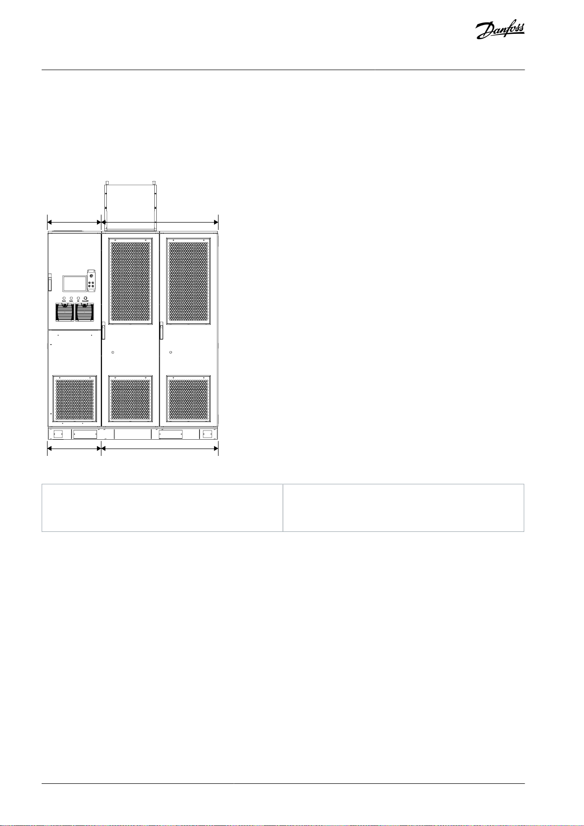
A
Control cabinet
B
Power cell cabinet
C
Junction cabinet
D
Transformer cabinet
VACON® 1000
Operating Guide
Product Overview
3.3 System Hardware
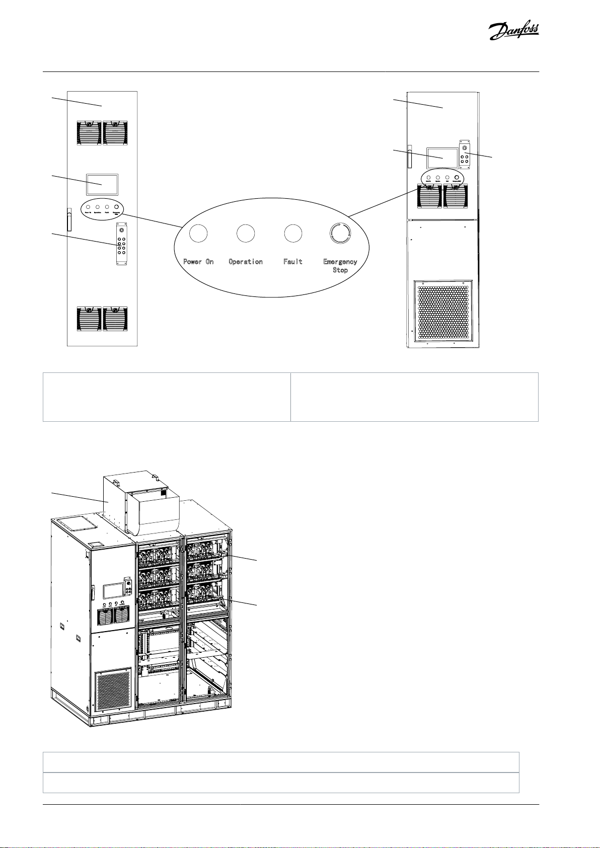
The VACON® 1000 medium-voltage drive consists of a controller cabinet, power cell cabinet, transformer cabinet, and junction cabinet. Other cabinets can be configured in accordance with customer requirements in the actual application.
There are two types of drive enclosure:
•
Standalone type with current ratings up to 215 A
•
Line-up type with current ratings 215–680 A (IEC ratings up to 11 kV, UL ratings up to 6.9 kV)
Illustration 1: Standalone System Structure
AQ363633621020en-000201 / 172F311714 | Danfoss A/S © 2021.06
Page 15
A B C D
e30bi639.10
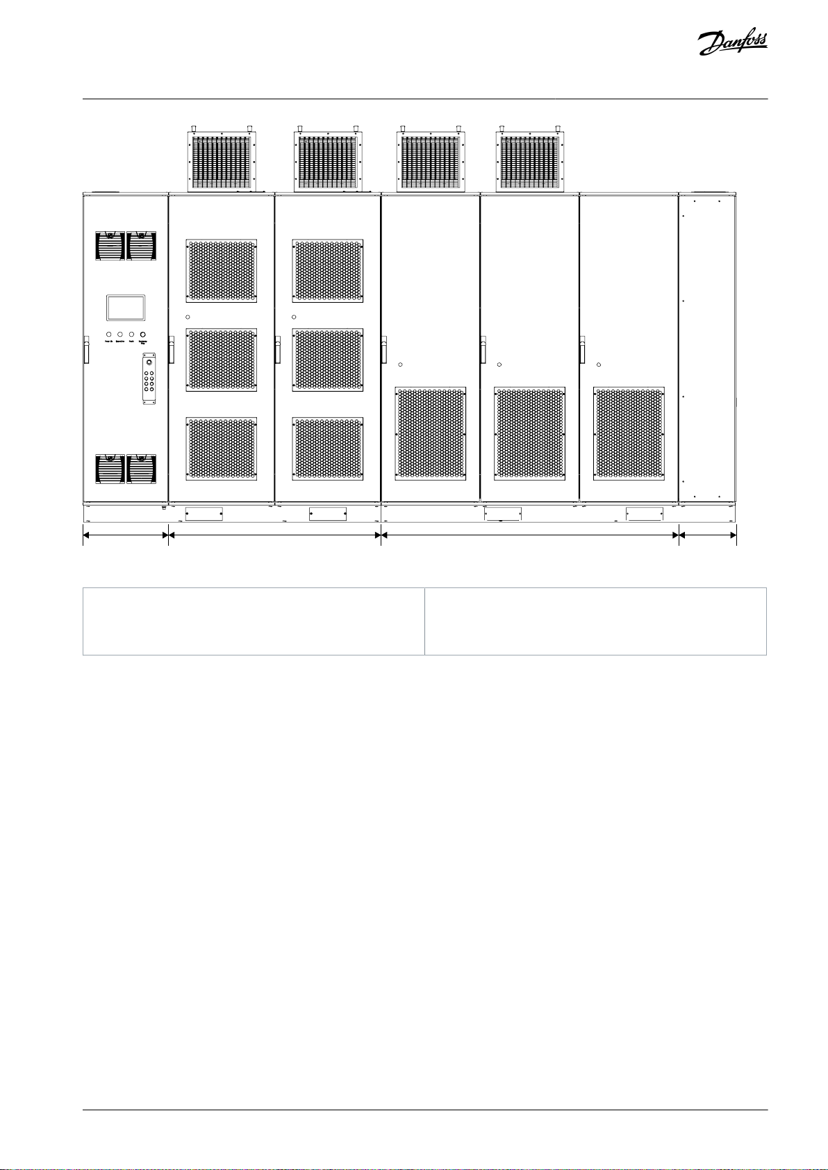
A
Control cabinet
B
Power cell cabinet
C
Transformer cabinet
D
Junction cabinet
VACON® 1000
Operating Guide
Product Overview
Illustration 2: Line-up System Structure
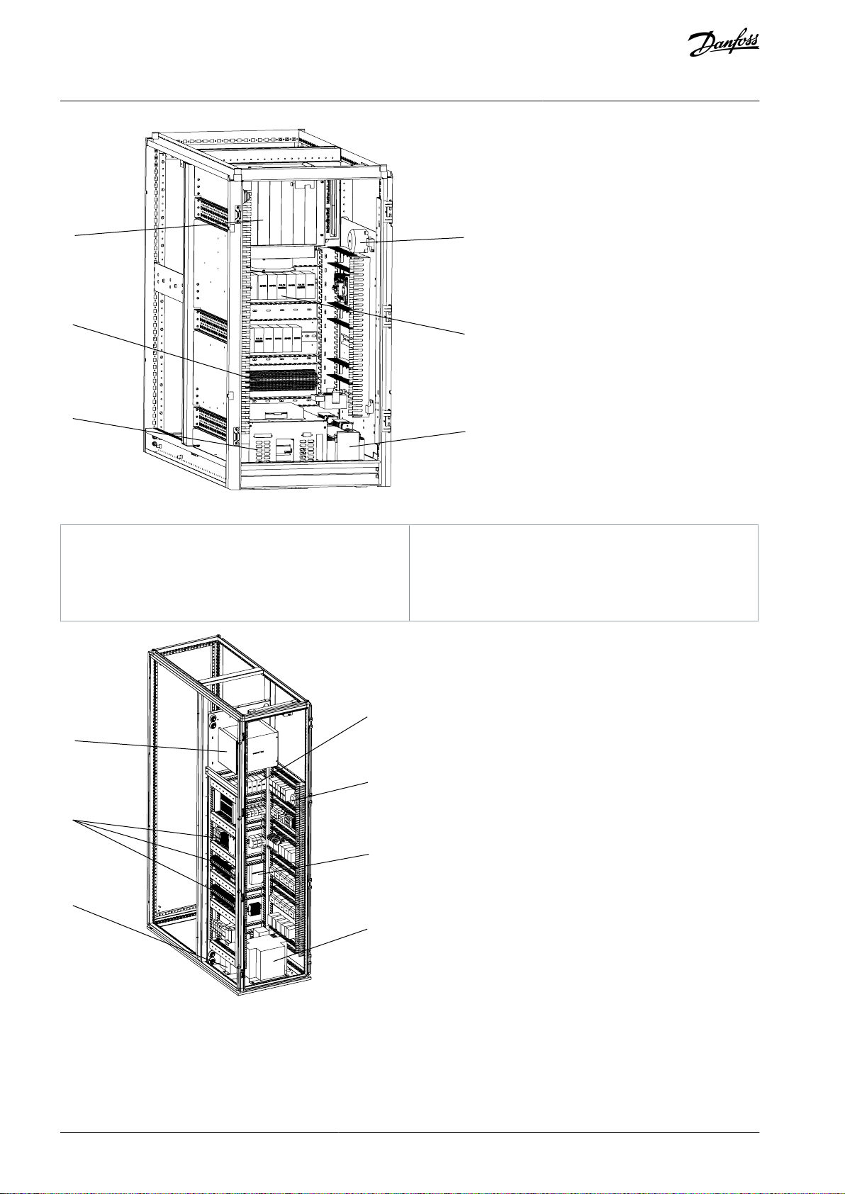
3.3.1 Control Cabinet
The control cabinet includes:
•
Main control system
•
PLC
•
HMI
•
Battery
•
Other accessories
AQ363633621020en-000201 / 172F3117 | 15Danfoss A/S © 2021.06
Page 16
e30bi642.10
A
B
C
D
E
F
A
Control rack
B
Terminal block
C
UPSDAirflow pressure switch
E
PLCFIsolation transformer
e30bi641.10
A
B
C
D
E
F
G
VACON® 1000
Operating Guide
Product Overview
Illustration 3: Control Cabinet in VACON® 1000 Standalone Systems
Illustration 4: Control Cabinet in VACON® 1000 Line-up Systems
AQ363633621020en-000201 / 172F311716 | Danfoss A/S © 2021.06
Page 17
A
Control rack
B
Terminal block
C
Battery
D
PLCEAirflow pressure switch
F
DC power supply
G
Isolation transformer
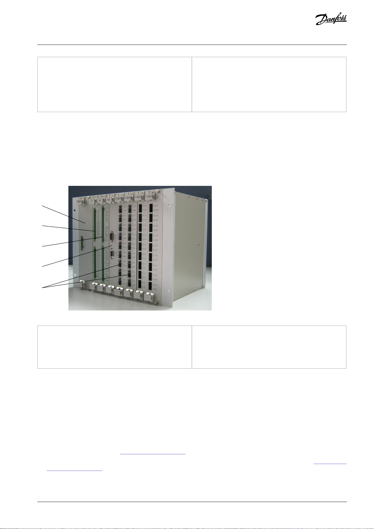
e30bi643.10
A
B
C
D
E
A
Power supply board
B
I/O board
C
A/D board
D
Main control board
E
Fiber optical boards
VACON® 1000
Operating Guide
The main control system is mounted in the control rack and consists of:
•
Main control board
•
I/O board
•
A/D board
•
Two fiber optical boards (extendable)
•
Power supply board
•
Bus motherboard, which connects the boards to each other.
Product Overview
Illustration 5: Main Control System
3.3.1.1 Controls and Indicators
The following are mounted on the control cabinet door:
•
High voltage power-on indicator: A green indicator, which indicates high voltage applied to the drive.
•
Operation indicator: A green indicator, which indicates that the drive is in operation.
•
Fault indicator: A red indicator, which indicates that the system is in “failure” state.
•
Emergency Stop button (E-stop): This button is used to break the high-voltage power of the drive when the system has an
emergency (such as unexpected incidents threatening the safety of the personnel or equipment). The button has a self-locking
function. Turn the button clockwise to reset and to turn power on again.
•
Human-machine interface: See 7 Human-Machine Interface.
•
Mechanical interlocking system: Standard in UL type drives and available as option +MMKI for IEC type drives. See 8.6.2 Mechan-
ical Interlocking System.
AQ363633621020en-000201 / 172F3117 | 17Danfoss A/S © 2021.06
Page 18
e30bi644.10
A
B
D
C
C
D
A
Line-up cabinet
B
Standalone cabinet
C
HMIDMechanical interlocking system
e30bi646.10
A
B
C
A
Cooling fan
B
Output current Hall sensor
VACON® 1000
Operating Guide
Product Overview
Illustration 6: Controls and Indicators on the Door of the Control Cabinet
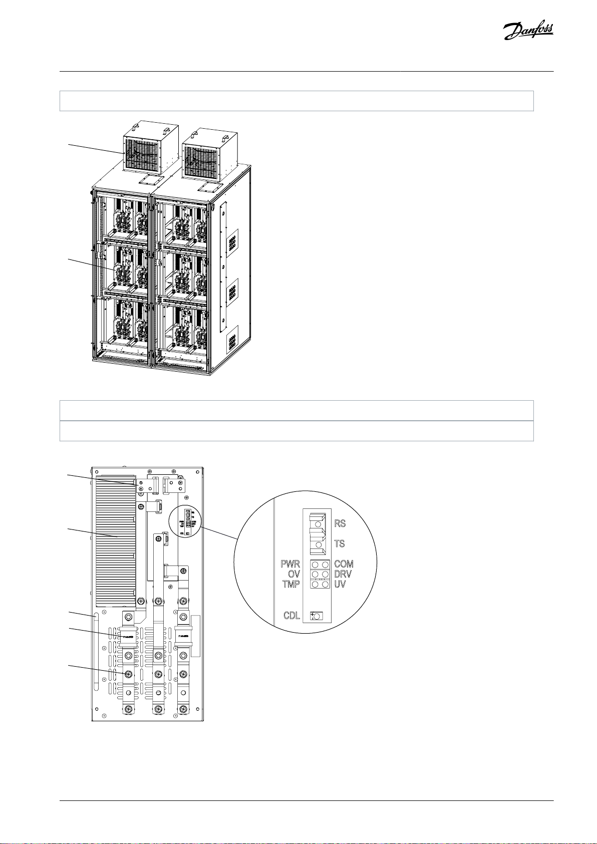
3.3.2 Power Cell Cabinet
The power cell cabinet contains the power cells and their accessories.
Illustration 7: Power Cell Cabinet in VACON® 1000 Standalone Systems
AQ363633621020en-000201 / 172F311718 | Danfoss A/S © 2021.06
Page 19
C
Power cell
e30bi645.10
A
B
A
Cooling fan
B
Power cell
e30bi647.10
A
B
C
D
E
VACON® 1000
Operating Guide
Product Overview
Illustration 8: Power Cell Cabinet in VACON® 1000 Line-up Systems
The power cells in the cabinet have the same electrical and mechanical parameters and can be replaced by each other.
Illustration 9: Power Cell
AQ363633621020en-000201 / 172F3117 | 19Danfoss A/S © 2021.06
Page 20
A
Output terminal
B
Heat sink
C
Handle
D
FuseEInput terminal
RS
Optical fiber (receive)
TS
Optical fiber (transmit)
COM
Communication fail indicator
DRV
Drive fault indicator
UV
Undervoltage indicator
TMP
Overtemperature indicator
PWR
Power indicator
OV
Overvoltage indicator
CDL
50 V DC-link voltage indicator
e30bi649.10
A
B
C
A
Cooling fan
B
Phase-shift transformer
C
Input current Hall sensor
VACON® 1000
Operating Guide
Product Overview
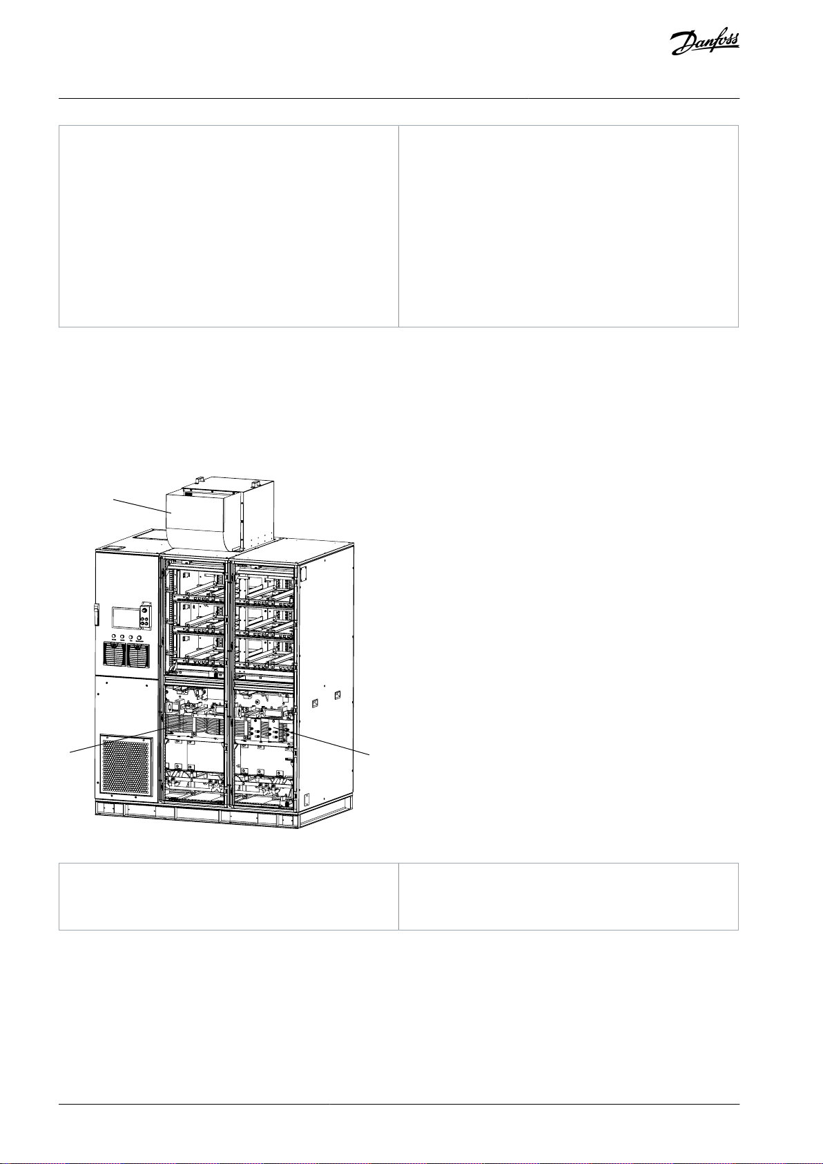
3.3.3 Transformer Cabinet
The transformer cabinet includes the phase-shift transformer and its accessories.
The transformer is integrated with the cabinet base through screws for the convenience of transportation and installation. The sys-
tem default setting is that, when the transformer temperature exceeds 95°C, the system reports an excessive high temperature
alarm but does not shut down. When the temperature exceeds 110°C, the system reports an extra-high temperature fault and shuts
down.
In standalone systems, the same fan is used to cool the transformer and power cell cabinets.
Illustration 10: Transformer Cabinet in VACON® 1000 Standalone Systems
AQ363633621020en-000201 / 172F311720 | Danfoss A/S © 2021.06
Page 21
e30bi648.10
A
B
C
D
A
Cooling fan
B
Phase-shift transformer
C
Input current Hall sensor
D
Output current Hall sensor
HV~
MCB
M
Junction
cabinet
Startup
cabinet
Drive
KM51
Output filter
cabinet
e30bi650.10
VACON® 1000
Operating Guide
Product Overview
Illustration 11: Transformer Cabinet in VACON® 1000 Line-up Systems
3.3.4 Junction Cabinet
The junction cabinet is used for field cable connections. See 6.5 Cable Entry and Termination.
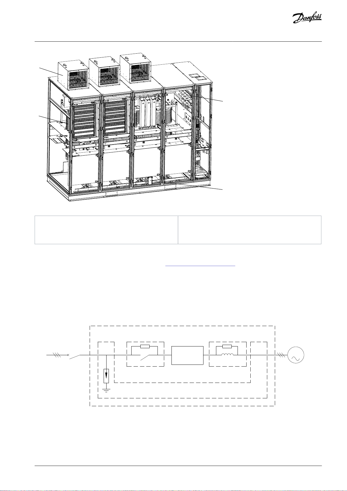
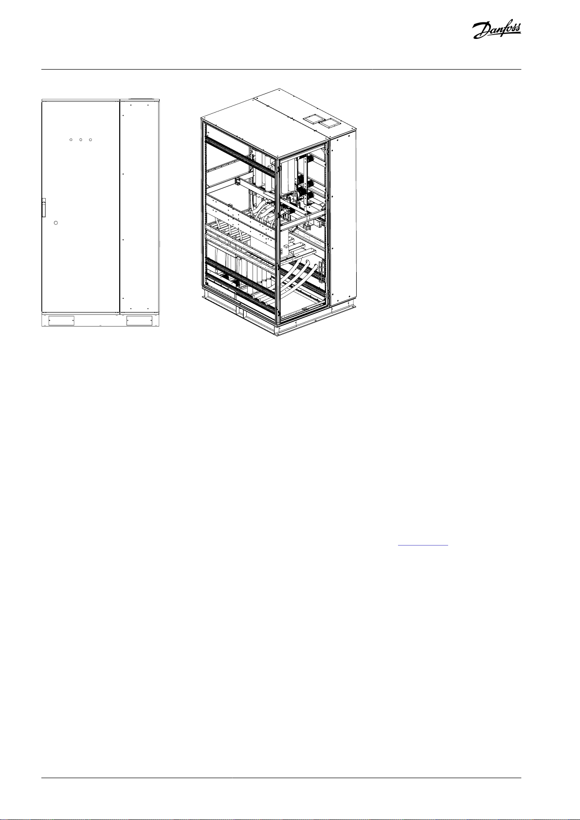
3.3.5 Start-up Cabinet
The start-up cabinet (+PSTC) is an option for the VACON® 1000 line-up systems. The main function of the start-up cabinet is to depress inrush currents that can lead to a dip in the supply voltage:
•
A phase-shifting transformer with a large capacity can produce a magnetizing surge as high as 6–8 times the rated current of
the transformer itself.
•
The power cells of the drive contain several capacitors, which require a large precharge current when high voltage is applied.
Illustration 12: Start-up Cabinet Primary Side Diagram
Install the start-up cabinet between the high-voltage power input and phase-shifting transformer. When the MCB of the drive is
closed, the start-up cabinet limits the magnetizing surge and charge current of the capacitance quickly and efficiently. After the
drive is powered up, the current-limiting resistance passes through the KM51 bypass, and the drive can function normally.
The main electrical components of the start-up cabinet are a high-voltage switch (vacuum contactor or vacuum breaker) and a current-limiting resistor.
AQ363633621020en-000201 / 172F3117 | 21Danfoss A/S © 2021.06
Page 22
e30bi651.10
VACON® 1000
Operating Guide
Product Overview
Illustration 13: Start-up Cabinet
The function of current-limiting resistance is to limit the primary current when a high voltage is connected. Each resistor can bear a
30 kJ energy during the power-up. The capacity of the drive defines how much resistance is needed in the start-up cabinet: the
larger the capacity, the more current-limiting resistors are needed.
The function of the high-voltage switch is to bypass the current-limiting resistor after the powering-up procedure, making the drive
function under normal load. If the rated current is small, a vacuum contactor can be used. If the rated current is large, a vacuum
breaker can be used.
Operation process
•
Power up the drive.
•
The control program confirms if the system is ready and if the cabinet switch is separated or not.
•
Power up the start-up cabinet and the control program counts the time it takes to complete the process. The process requires
about 5 s.
•
The closing of the start-up cabinet switch bypasses the charged resistor and the drive has status 'running allowed'.
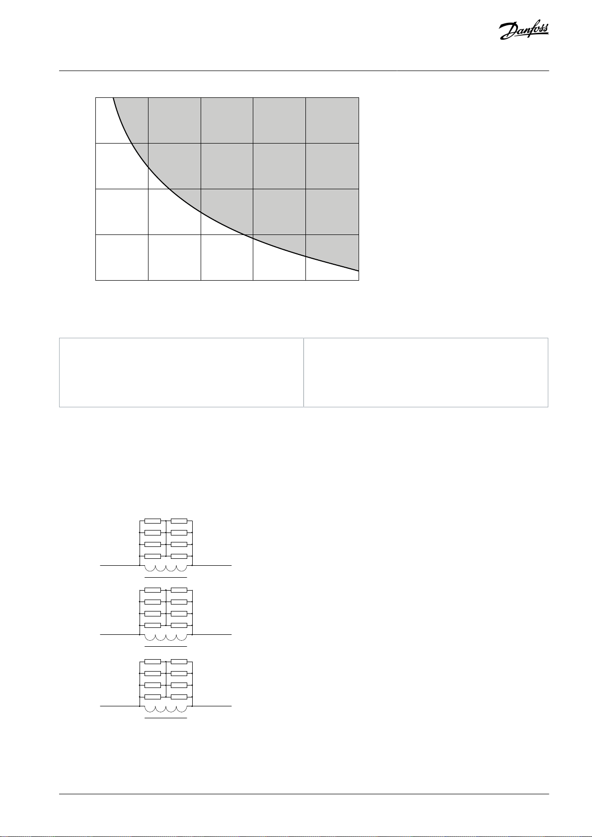
When to select the Start-up cabinet option?
The MCB protection at the installation site must not trip because of the inrush current when the drive is powered up or in normal
overload conditions. The overcurrent protection of the MCB must be set in the grey area shown in Illustration 14.
If the MCB meets these requirements, the start-up cabinet is not required. It is important to verify this condition, especially in retrofit
applications where a circuit breaker is already installed at the motor control center panel.
Even if it is not required, a start-up cabinet can still be installed to:
•
Reduce inrush current.
•
Reduce stresses in the electrical installation during the drive power-up operation.
AQ363633621020en-000201 / 172F311722 | Danfoss A/S © 2021.06
Page 23
20T
O
t(I)
I/I
LN
0.2I
ratio
0.4I
ratio
0.6I
ratio
0.8I
ratio
I
ratio
15T
O
10T
O
5T
O
0
0
e30bj032.10
I
Inrush current
ILNRated input current of the drive
I
ratio
I/I
LN
t(I)
Time of the inrush current decay
TOThe basic period: 20 ms for 50 Hz or 16.7 ms for
60 Hz
L71-a
L71-b
L71-c
To
inverter
To
motor
R72A
R74A
R78A
R76A
R71A
R73A
R77A
R75A
R72B
R74B
R78B
R76B
R71B
R73B
R77B
R75B
R72C
R74C
R78C
R76C
R71C
R73C
R77C
R75C
e30bi652.10
VACON® 1000
Operating Guide
Illustration 14: Overcurrent Protection Setting Area
Product Overview
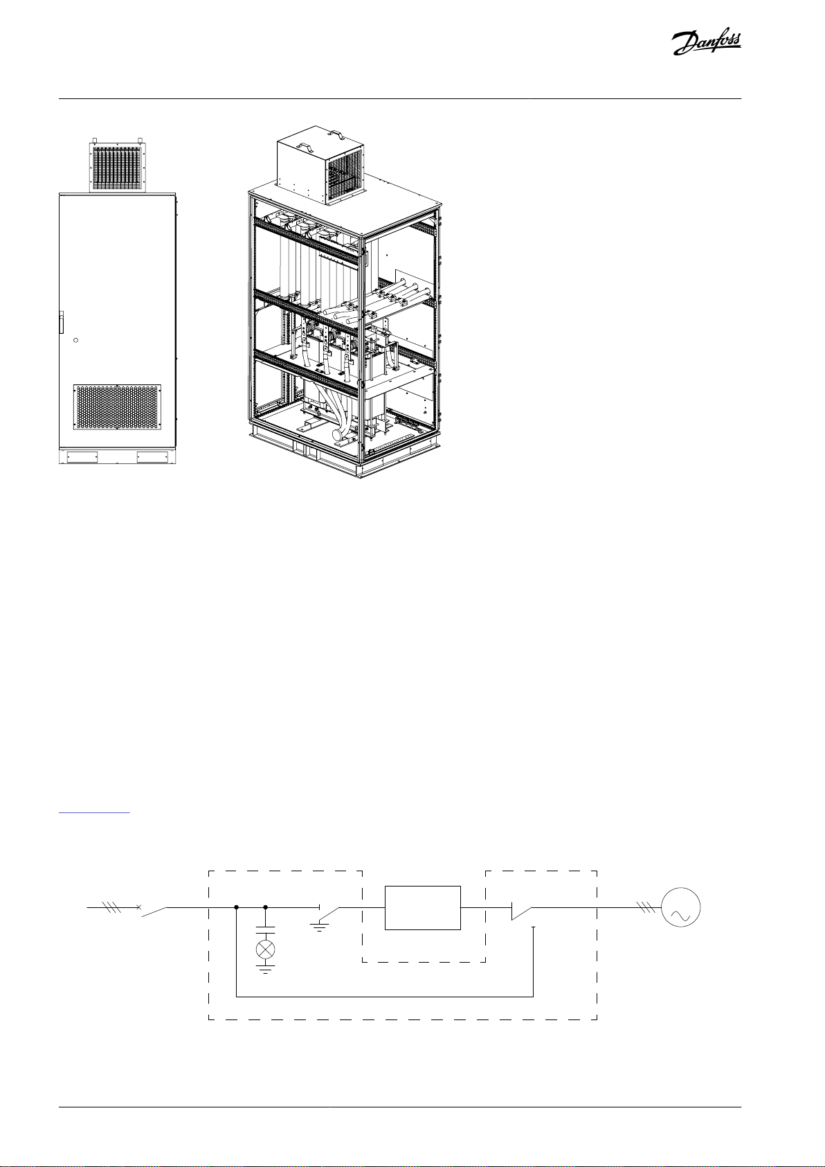
3.3.6 Output Filter Cabinet
The output filter cabinet is an optional cabinet which is connected at the output of the drive, between the inverter and motor. The
filter is used to:
•
Reduce the dU/dt of the voltage waveform.
•
Prevent resonance/overvoltage caused by motor cables.
•
Reduce the charging current of the cable.
Illustration 15: Output Filter Cabinet Circuit Diagram
Install the output filter cabinet between the drive and motor. The filter consists of a reactor and paralleling damping resistors. The
reactor decreases the rising edge of the PWM. The resistor damps the resonance caused by the reactor and stray inductance.
AQ363633621020en-000201 / 172F3117 | 23Danfoss A/S © 2021.06
Page 24
e30bi653.10
HV~
MCB
M
Manual bypass cabinet
QS41
DN41
QS42
QS43
Drive
e30bi747.10
VACON® 1000
Operating Guide
Product Overview
Illustration 16: Output Filter Cabinet
When to select the Output Filter cabinet option?
The need for an output filter is application and case specific. Several things must be considered to find out if a dU/dt Filter is required:
•
The type of the motor.
•
The type of the motor cable.
•
The length of the motor cable.
To evaluate if a dU/dt Filter is required, contact Danfoss.
3.3.7 Bypass Cabinet
Different bypass cabinets are available as options:
•
Manual bypass cabinet
•
Automatic bypass cabinet
•
Synchronous transfer cabinet
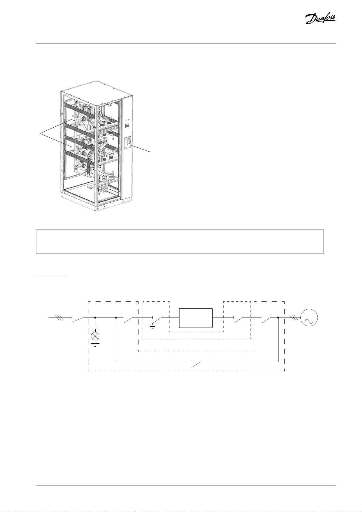
3.3.7.1 Manual Bypass Cabinet
Illustration 17 shows a typical bypass cabinet configuration, where:
•
QS41 is a single-pole isolation switch with a manual grounding knife gate.
•
QS42 and QS43 are double-pole double-throw manual knife gate isolation switches.
Illustration 17: Manual Bypass Cabinet Circuit Diagram
The bypass cabinet includes an isolation switch, which:
AQ363633621020en-000201 / 172F311724 | Danfoss A/S © 2021.06
Page 25
A
B
e30bi750.10
A
Manual knife gate switch
B
Dual-isolation switch panel
HV~
MCB
M
Automatic bypass/Synchronous transfer cabinet
Manual bypass cabinet
QS41KM41 KM42
KM43
DN41
QS42
Drive
e30bi748.10
VACON® 1000
Operating Guide
•
Realizes the electrical isolation between the phase-shift transformer and the power distribution system.
•
Provides the power frequency and variable frequency switching function and related electrical protection measures.
Product Overview
Illustration 18: Manual Bypass Cabinet
3.3.7.2 Automatic Bypass Cabinet
Illustration 19 shows an automatic bypass cabinet configuration, where:
•
KM41–KM43, high-voltage vacuum contactors.
•
QS41–QS42, manual separation knife switches.
Illustration 19: Automatic Bypass Cabinet Circuit Diagram
When the drive is running:
•
QS41 and QS42 are closed.
•
KM41 and KM42 are closed.
•
KM43 is open.
When the drive is bypassed:
•
KM41 and KM42 are open.
•
KM43 is closed.
When maintenance is performed on the drive:
AQ363633621020en-000201 / 172F3117 | 25Danfoss A/S © 2021.06
Page 26

VACON® 1000
Operating Guide
•
QS41 and QS42 are open.
•
KM41 and KM42 are open.
•
KM43 is closed.
The sequence in which the drive is switched from running to bypassed:
•
1. KM41 is opened.
•
2. KM42 is opened.
•
3. KM43 is closed.
Secondary Control Logic
The three switches KM41–KM43 use assistant contact interlock to ensure that the time course is followed.
•
KM41 does not open and KM42 does not act when the normally closed contactor of KM41 is connected into the opening circuit
of KM42.
•
The normally closed contactor of KM42 is connected to the MCB-closed circuit of KM43.
•
The normally closed contactor of KM43 is connected to the MCB-closed circuit of KM42.
•
KM43 is not able to close the MCB when KM42 is not opening.
•
KM42 is not able to close MCB when KM43 is not opening.
The status of the five switches KM41–KM43 and QS41–QS42 is monitored through the PLC.
•
If any switch is not at the right working position, the system does not allow the MCB to close, and powering up high voltage to
the system is forbidden.
•
If the drive goes into fault, the system breaks the switch automatically to cut off the HV input for safety, if KM41 is not able to
open during the process of VF switching to working frequency automatically.
The two switches KM42 and KM43 control the function of reserving postponed action in the circuit, which can adjust the action
interval of the switch during the process of VF switching to working frequency. It can be more convenient to calibrate the machine
on site according to the status of the electric motor and load, to switch speed reasonably to avoid an overcurrent malfunction because of the electric motor remanence.
Product Overview
AQ363633621020en-000201 / 172F311726 | Danfoss A/S © 2021.06
Page 27
e30bi751.10
AC/DC 220 V
501
ZK1
FU21
504
415
415
415
415
415
415
415
415
415
415
415
417
1
2
1
2
5
6
7
8
3
4
542
543
548
527
530
537
538
539
533
544
415
540
541
524
536
535
534
546
413
532
528
KA12
SF2
SA3
SB2
SF1
SF2
SB1
SF1
KT2
KA1-I
KA1
KA1
KA1
K4
SB3
SA2
SA1
KA2
KT3
KT3
KT3
KT2
KT1
KT1
KM43
KM43
KM43
KM42
KM41
KA2
KA2
KA2
KA2
KA1
KA1-II
KA2-I
KA2-II
KT1
KM42
KM43
KM41
KM41
KM42
KM43 closing coil
KM41 opening
coil
KM42 opening coil
KM43 opening coil
KM42 open switch
KM43 opening switch
KM43 close switch
KM41 close switch
KM41 close switch
KM42 close switch
SF1
503
505
AC 220 V
Micro breaker
Fuse
PF auto transfer switch
VF to PF manual transfer switch SF2
PF to VF manual transfer switch SF2
KA2 self-lock circuit
Operation mode switch SF1
KM41 open push button SB1
KM43 open push button SB3
KM42 close push button SA2
KM41 close push button SA1
KM42 open command
KM43 open command
KM42 open push button SB2
KM43 close command
KM41 close command
KM42 close command
Time relay
Time relay circuit
KM43 close push button
KM42 close coil
KM41 close coil
e30bi752.10
VACON® 1000
Operating Guide
Product Overview
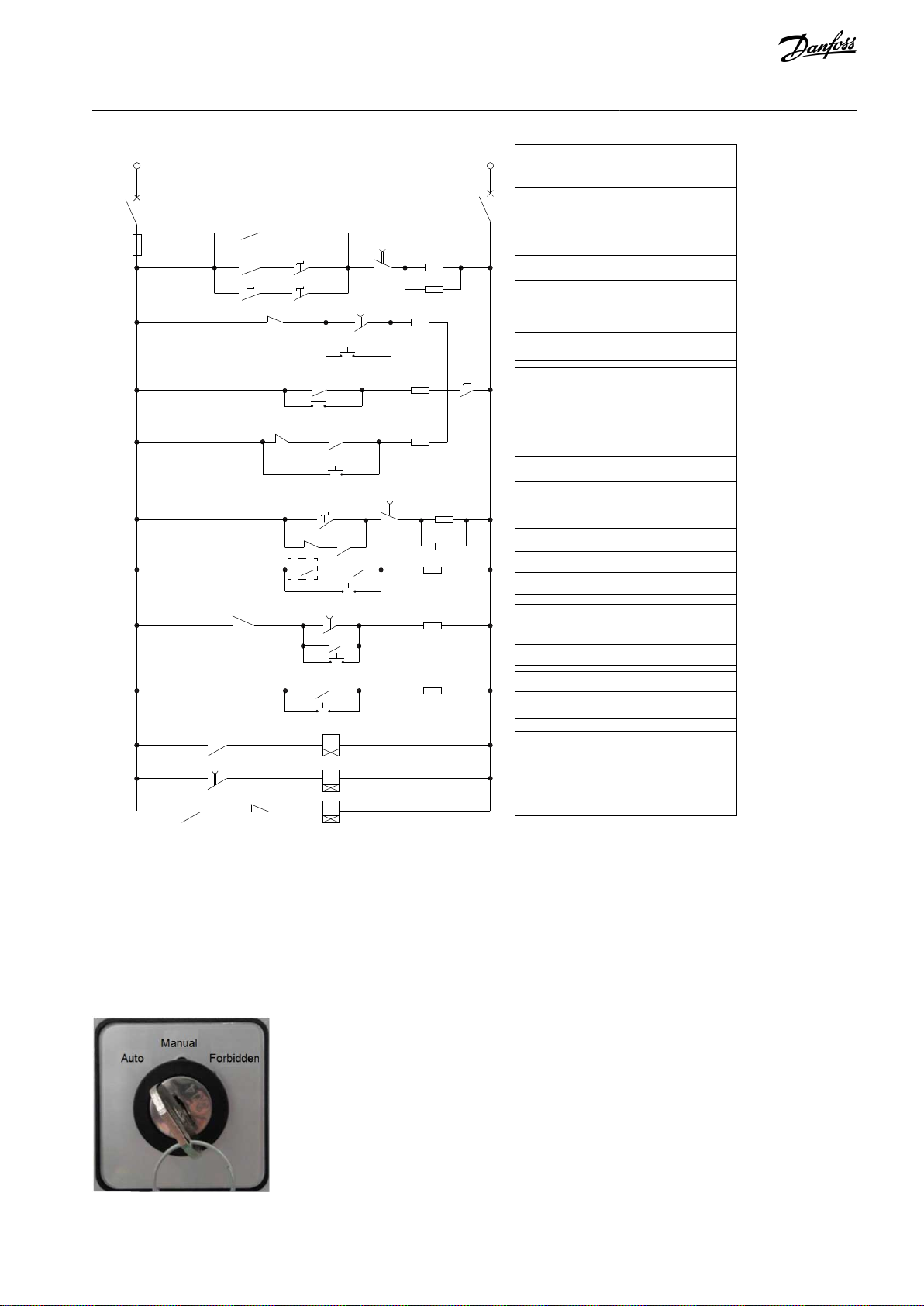
Illustration 20: Secondary Control Logic Diagram of VF Switching to PF
Operation Mode Switches
Switch SF1 is used to select the working mode to prevent incorrect operation.
•
Auto: Allows switching to PF bypass automatically when the drive is in a serious fault.
•
Manual: Allows manual switching to working-frequency bypass according to the real production requirements when the drive is
normally running.
•
Forbidden: If the production conditions do not allow the switching to working-frequency bypass, this mode can be selected to
prevent incorrect operation.
Illustration 21: Working Mode Selection Switch SF1
AQ363633621020en-000201 / 172F3117 | 27Danfoss A/S © 2021.06
Page 28
e30bi753.10
HV~
MCB
M
Automatic bypass/Synchronous transfer cabinet
Manual bypass cabinet
QS41KM41 KM42
KM43
DN41
QS42
Drive
e30bi748.10
VACON® 1000
Operating Guide
Product Overview
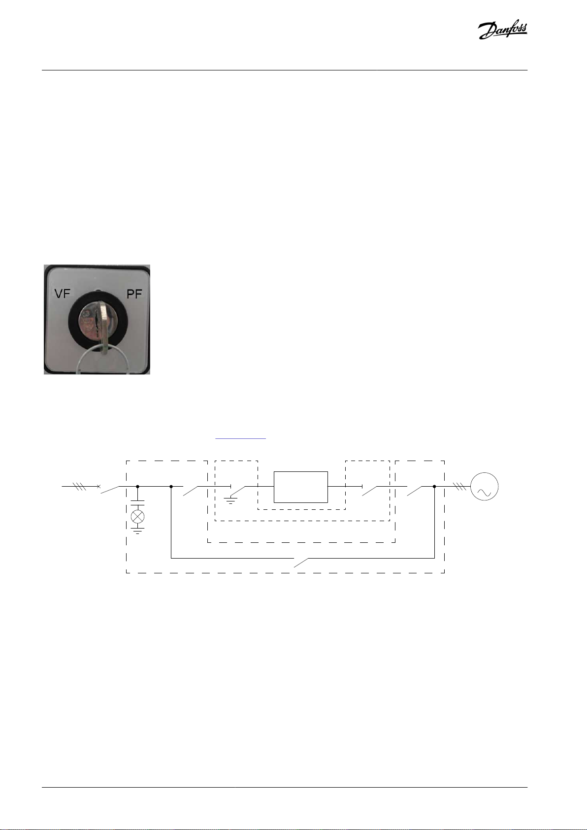
Switch SF2 is used to select between variable-frequency (VF) and power-frequency (PF) switching.
•
When the automatic bypass cabinet is in manual operation mode, and switch SF2 is in PF position, the drive switches the system
to PF bypass status automatically.
•
When switch SF2 is in VF position, the drive can switch from power-frequency bypass status to variable-frequency mode automatically (QS41 and QS42 must be closed). This function needs the coordination of engine racing starting-up. Therefore, engine
racing must be enabled and must comply with all the related electric motor parameters.
•
VF logic sequence:
-
KM41 is closed.
-
If self-detection shows normal after 10 s, bypass switch KM43 is opened.
-
KM42 is closed.
-
Automatic engine racing of the drive starts up.
-
PF is switched to VF.
Illustration 22: Switching Mode Selection Switch SF2
3.3.7.3 Synchronous Transfer Cabinet
The synchronous transfer function can realize undisturbed transfer between the grid and the drive, and reduce the impact on the
motor and grid. The primary circuit is shown in Illustration 23. The switching devices and cabinets are the same as in the automatic
bypass cabinet. QS41 and QS42 are for drive maintenance use and are closed during operation.
Illustration 23: Synchronous Transfer Cabinet Circuit Diagram
Process sequence of load transfer from the drive to the grid
•
Initial state: KM41 and KM42 are closed, and KM43 is open.
•
Phase lock: The drive runs to grid frequency and starts to lock phase to grid voltage.
•
Synchronous transfer: After phase lock, KM43 is closed and the load transfer to grid is started.
•
Synchronous transfer finished: After the load transfer, KM42 and KM41 are opened.
Process sequence of load transfer from the grid to the drive
•
Initial state: KM41 and KM42 are open, and KM43 is closed.
•
Phase lock: KM41 is closed. The drive runs to grid frequency and starts to lock phase to grid voltage.
•
Synchronous transfer: After phase lock, KM42 is closed and the load transfer to the drive is started.
•
Synchronous transfer finished: After the load transfer, KM43 is opened.
AQ363633621020en-000201 / 172F311728 | Danfoss A/S © 2021.06
Page 29
Motor
Phase-shift
Transformer
-12°
-24°
0°
12°
24°
Power Cells
≈
≈
≈
≈
≈
≈
≈
≈
≈
≈
≈
≈
≈
≈
≈
≈
≈
≈
≈
≈
≈
≈
≈
≈
≈
≈
≈
≈
≈
≈
Source
e30bi654.10
Drive series
Number of power cells per phase
System cell number
Output phase voltage (V)
Output line voltage (V)
2.4 kV
391385
2400
3 kV39
1732
3000
3.3 kV
391905
3300
4.16 kV
4122400
4160
6 kV515
3464
6000
VACON® 1000
Operating Guide
Product Overview
3.4 System Operation
3.4.1 Main Circuit
The typical main circuit topological structure diagram of VACON® 1000 medium-voltage drive is shown in Illustration 24.
Illustration 24: Main Circuit Diagram of VACON® 1000
The phase-shift rectifier transformer is a 3-phase air-cooled dry-type transformer directly connected with the incoming high voltage.
The secondary windings use an extended delta connection, which can lower the content of the input side current distortion. The
phase-shift angle between the secondary windings can be calculated according to the following formula:
Phase − shiftangle =
The secondary windings of the transformer provide input power for each power cell respectively. The number of secondary windings and the phase-shift angle between the windings are determined according to the voltage level and structure of the drive, as
Numberofpowercells
shown in Table 2.
Table 2: Power Cell Configuration for VACON® 1000
60°
AQ363633621020en-000201 / 172F3117 | 29Danfoss A/S © 2021.06
Page 30
Drive series
Number of power cells per phase
System cell number
Output phase voltage (V)
Output line voltage (V)
6.6 kV
6183810
6600
6.9 kV
6183984
6900
10 kV
8245774
10000
11 kV
9276351
11000
PWM1
PWM2
PWM3
PWM4
PWM5
PWM6
Time (ms)
Output phase voltage
0 4 8 12 16
20
e30bi655.10
VACON® 1000
Operating Guide
Product Overview
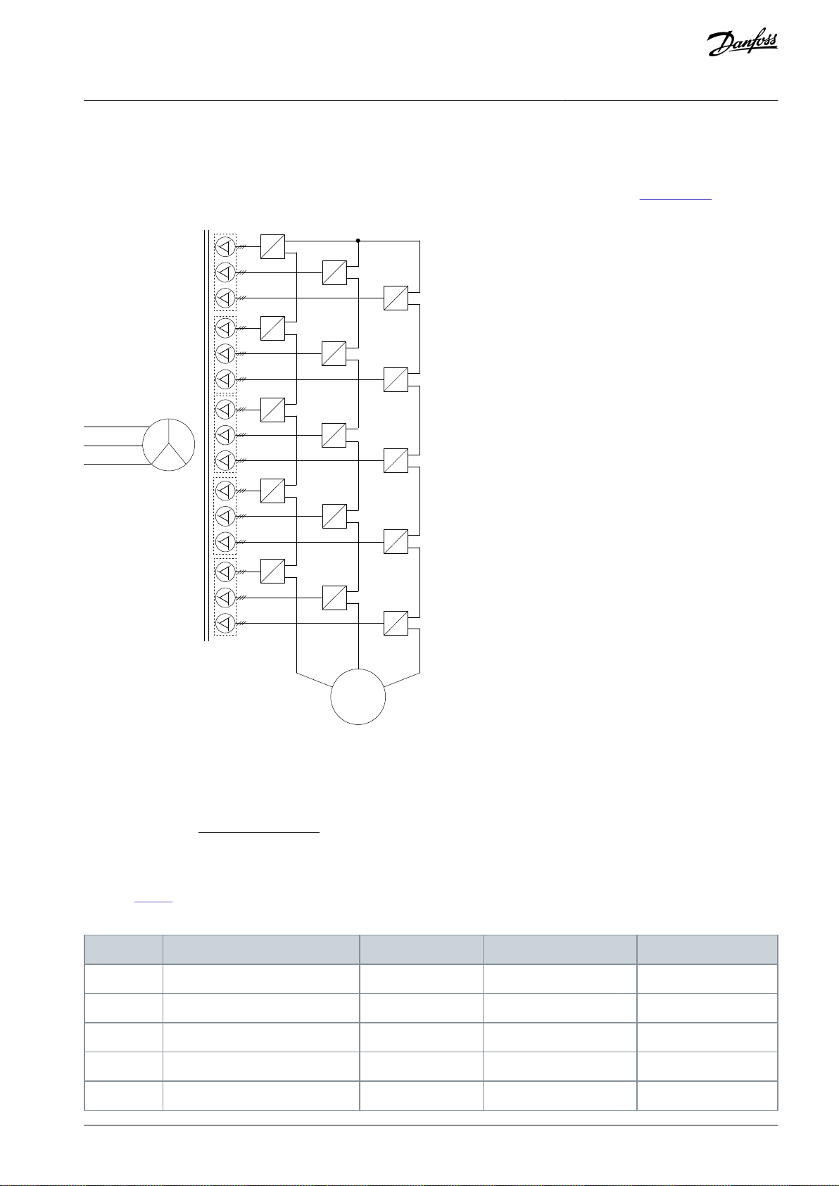
3.4.2 Power Cells
The power cell is the basic module of the medium-voltage drive, which produces a variable voltage and frequency output. It is composed of fast acting fuses, a rectification bridge, DC-link capacitance, IGBT inverting bridge, and so on.
The input terminals of the power cells are connected with the 3-phase winding of the secondary side of the phase-shift transformer.
The 3-phase diode provides full-wave rectification to charge the DC-link capacitance, and the voltage on the capacitance is provided to the H-bridge 1-phase bridge inverter circuit formed by 4 IGBTs.
The power cell receives signals through optical fibers, and controls the closing and opening of the S1–S4 IGBTs by using PWM modulation mode to output a 1-phase impulse modulated waveform. Each cell has only 3 possible output states:
•
When S1 and S4 are closed, the state of the output voltage VUV is VDC.
•
When S2 and S3 are closed, the output voltage VUV is -VDC.
•
When S1 and S3 or S2 and S4 are closed, the output voltage VUV is 0.
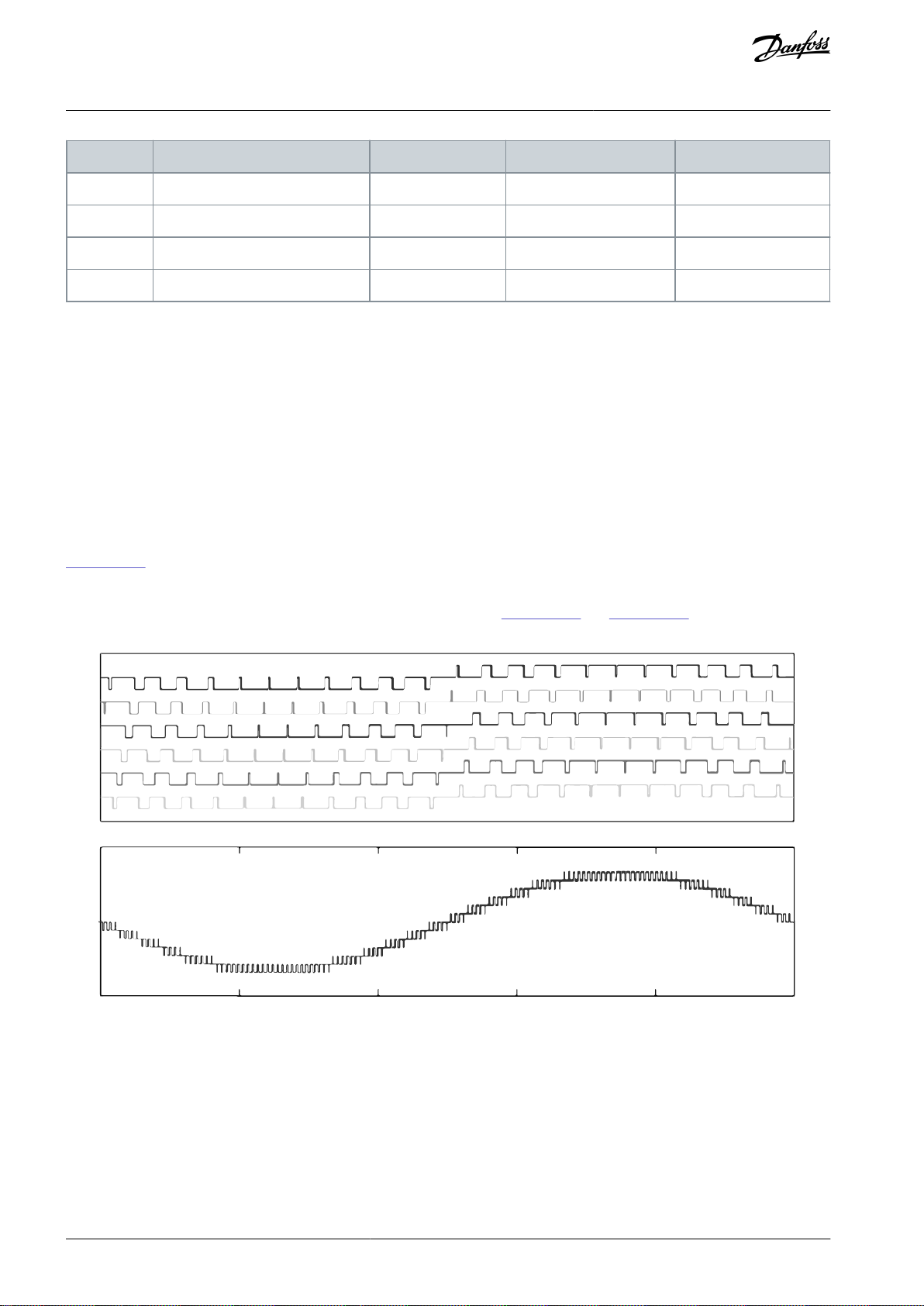
Illustration 25 shows the waveform diagram of the output voltage of each power cell and the superimposed output phase voltage
waveform when 6 cells are connected in series. As shown in the figure, 13 voltage levels are obtained through connecting the 6
power cells in series. The increasing number of the voltage levels reduces the distortion content of the output voltage and simultaneously lowers the risk of damaging the motor insulation caused by dU/dt. Illustration 26 and Illustration 27 are the waveform diagrams of the output voltage and current of the drive when loaded by a motor.
Illustration 25: Output and Phase-Voltage Diagrams
AQ363633621020en-000201 / 172F311730 | Danfoss A/S © 2021.06
Page 31

e30bi656.10
e30bi657.10
VACON® 1000
Operating Guide
Illustration 26: Output Line-to-line Voltage Waveform
Illustration 27: Output Current Waveform
Product Overview
Each power cell has an independent cell control board and driver board. The cell control board receives the PWM signal transmitted
by the main control system through optical fiber to control the IGBT. Simultaneously, the status information of each power cell is
fed back to the main control system by the cell control board through optical fiber. The driver board is used to drive the IGBT and
feedback the failure signal of the IGBTs to the cell control board, such as short-circuit protection.
3.4.3 Control System
An example structure diagram of the control system is shown in Illustration 28. The number of power cells depends on the nominal
voltage of the drive.
AQ363633621020en-000201 / 172F3117 | 31Danfoss A/S © 2021.06
Page 32

Motor
Phase-shifted
transformer
Input current sensor
Output current sensor
Input
Power
-12°
-24°
0°
12°
24°
Optical
fiber
communication
Main
control
system
User
end
Power cells
PLC
HMI
I/O
signals
RS485
RS485
4-20mA/0-10V
Analog signals
Digital signals
≈
≈
≈
≈
≈
≈
≈
≈
≈
≈
≈
≈
≈
≈
≈
≈
≈
≈
≈
≈
≈
≈
≈
≈
≈
≈
≈
≈
≈
≈
RS485
Auxiliary winding
Input
voltage
sensor
Output
voltage
sensor
e30bi658.10
VACON® 1000
Operating Guide
Product Overview
Illustration 28: Structure Diagram of the Control System
The main functions of the main control system include:
•
Digital input and output
•
Analog input and output
•
PWM control signal generation of each power cell
•
Encoding and decoding of the control signal
•
System self-diagnosis
•
Delivery of various implementation instructions
•
Collection and handling of various failures
•
Communication with external systems
To enhance the flexibility at the site application, a PLC is used for the logical processing of the internal switching signals, site operation signals, and status signals of the medium-voltage drive. The VACON® 1000 medium-voltage drive uses a high-quality PLC to:
•
Accomplish the input and output drive signal control
•
Protection and interlocking
•
External failure detection
•
Communication with the main control system
•
Control of the human-machine interface
The HMI (Human-machine interface) is based on a high-definition liquid-crystal touch-type screen. It is easy to operate and is used
to set functional parameters, display and record the system status, operation status, and faults through the connection to the PLC.
See 7 Human-Machine Interface.
AQ363633621020en-000201 / 172F311732 | Danfoss A/S © 2021.06
Page 33

PWM
Inverter
Coordinate
transformation
Flux & Speed
Estimation
Coordinate
transformation
Motor
Voltage & Current
measurements
Calculation
Calculation
Calculation
Calculation
Calculation
Encoder
ω
*
ω
T
e
*
T
e
*
i
q
*
i
d
*
i
d
*
u
d
*
u
d
*
i
d
i
d
Ψ
Ψ
r
Ψ
r
*
iAiBi
C
u
A
u
A
*
u
B
*
u
C
*
uBu
C
i
q
i
q
u
d
u
q
i
q
*
u
q
*
u
q
*
e30bi659.10
Code
Voltage (V)
Frequency (Hz)
024
240060030
300060033
330050041
416060060
600050066
660050069
690060100
10000
50
110
11000
50
VACON® 1000
Operating Guide
Product Overview
VACON® 1000 delivers high performance control accuracy using Vector Control. The ability to control motor flux and speed independently yields fast dynamic response to load fluctuations and high torque at low speeds, including during motor startup. The
control diagram is shown in Illustration 29.
Both encoder and sensorless Vector Control approaches are available for selection. The speed sensors can be installed depending
on actual application conditions. For cases without the speed sensors, the system can still provide fast dynamic responses and high
output torque when the motor is running at low speed.
Illustration 29: Vector Control Diagram
3.5 Type Code Description
The type code for VACON® 1000 has four basic parts and option codes.
•
VACON1000-ED-019-024+____+____
1. Product series
VACON® 1000. This part of the code is always the same.
2. Product type
The VACON® 1000 product.
•
ED: Enclosed Drive
3. Nominal output current
For example, -040 = 40 A. See the available output currents in 11.2 Power Ratings and Dimensions.
4. Nominal system voltage
Table 3: Available System Voltages
AQ363633621020en-000201 / 172F3117 | 33Danfoss A/S © 2021.06
Page 34

Option
Description
Degree of protection
+IP42
Protection rating IP42
Input frequency
+LS50
50 Hz input frequency
+LS60
60 Hz input frequency
I/O options
+IAF1
Synchronous transfer I/O (8DI/8DO)
+IBF2
Advanced control module
+ICF3
Excitator control I/O
+IDF4
PID control module
+IEF5
Motor temperature module (8 channels)
I/O PLC options
+IAP1
PLC DI module (16 DI)
+IBP2
PLC DIO module (8DI/8DO)
+ICP3
PLC AIO module (2AI/4AO)
+IDP4
Motor temperature module (8 channels); Not compatible with all bypass options
Fieldbus options
+S_E2
Modbus RTU
+S_E5
PROFIBUS DP-V0
+S_E6
CANopen
+S_E7
DeviceNet
™
+S_EC
EtherCAT
+S_EI
Modbus TCP
+S_EL
POWERLINK
+S_EN
ControNet
™
+S_EP
PROFINET I/O
+S_EQ
EtherNet/IP
™
User interface
VACON® 1000
Operating Guide
5. Options
Optional components or specifications.
See the available codes in 3.6 Available Options.
3.6 Available Options
Table 4: Available Options for VACON® 1000
Product Overview
AQ363633621020en-000201 / 172F311734 | Danfoss A/S © 2021.06
Page 35

Option
Description
+MHMI
HMI 10"
System firmware
+F101
Induction motor
+F102
Synchronous motor (external exciter)
Cell bypass
+PPCB
Power cell bypass
Cell redundancy
(1)
+PPCR
Power cell redundancy
Cabinet bypass
(1)
+PMBP
Manual motor bypass
+PABP
Automatic motor bypass
+PSBP
Synchronous transfer (1 motor only)
+PSB2
Engineered synchronous transfer
Input devices
(1)
+PSTC
Start-up cabinet available for drives >215 A
Output devices
(1)
+POCK
Reactor for synchronous transfer
+PODU
dU/dt filter for cable <2000 m
Cabinet options
+QDFR
Cooling fan redundancy
+QDEX
External cooling fan supply
+QSPD
Surge protection device (standard for UL, optional for IEC variants)
+QT01
Control power without heater XFMR
+QT02
Control power with heater XFMR
Mechanical options
+MHET
Heater + Thermostat
+MHEH
Heater + Humidity sensor
+MMKI
Mechanical key interlock (standard for UL, optional for IEC variants)
Input voltage options
(1)
+I023
Input voltage: 2300 V
+I024
Input voltage: 2400 V
+I030
Input voltage: 3000 V
VACON® 1000
Operating Guide
Product Overview
AQ363633621020en-000201 / 172F3117 | 35Danfoss A/S © 2021.06
Page 36

Option
Description
+I033
Input voltage: 3300 V
+I040
Input voltage: 4000 V
+I041
Input voltage: 4160 V
+I042
Input voltage: 4200 V
+I048
Input voltage: 4800 V
+I050
Input voltage: 5000 V
+I060
Input voltage: 6000 V
+I063
Input voltage: 6300 V
+I066
Input voltage: 6600 V
+I069
Input voltage: 6900 V
+I072
Input voltage: 7200 V
+I084
Input voltage: 8400 V
+I100
Input voltage: 10000 V
+I110
Input voltage: 11000 V
+I114
Input voltage: 11400 V
+I120
Input voltage: 12000 V
+I124
Input voltage: 12400 V
+I132
Input voltage: 13200 V
+I138
Input voltage: 13800 V
Environment
+THAL
High altitude, >2000 m above sea level
+T50C
50°C ambient temperature operation
Seismic zone
+SZ04
Zone 4
Factory Acceptance Test
+QFAT
FAT
+QFNO
No-load FAT
VACON® 1000
Operating Guide
Product Overview
1
If this option is selected, it can impact the overall dimensions and weight of the product.
3.6.1 Cabinet Bypass
See 3.3.7 Bypass Cabinet.
3.6.2 Input Devices
See 3.3.5 Start-up Cabinet.
AQ363633621020en-000201 / 172F311736 | Danfoss A/S © 2021.06
Page 37

Option
+MHET
+MHEH
Devices
Heater and thermostat
Heater and hygrostat
Application
area
Low operation temperature area (-5 °C...0 °C)
High relative humidity and condensation area
Purpose
To warm up the drive before turning it on if the temperature is lower than 0 °C (but higher than -5 °C). The
low temperatures exceed the rated operation temperature of the micro chips and capacitors inside control
cabinet and power cells.
To prevent devices and cabinets from condensation and
corrosion in a high relative humidity operation environment, otherwise break down or flashover can occur during operation.
Location
Control cabinet and power cell cabinet
Power cell cabinet, transformer cabinet, junction cabinet, or any other cabinets with high voltage parts
Key parameters
Thermostat setting range: -10...50°C (14–122 °F),0 °C as
default preset value.
Heater power: 220 V, 400/150 W, depending on the
cabinet size.
Hygrostat setting range: 35–95% RH, 80% as default preset value.
Heater power: 220 V, 400/150 W, depending on the cabinet size.
VACON® 1000
Operating Guide
3.6.3 Output Devices
See 3.3.6 Output Filter Cabinet.
3.6.4 Mechanical Options
Heater Options +MHET/+MHEH
Table 5: Heater Options +MHET and +MHEH
Product Overview
Mechanical Interlocking System, +MMKI
See 8.6.2 Mechanical Interlocking System.
3.7 VACON® 1000 PC Tool
The VACON® 1000 PC Tool is an Ethernet-based computer-assisted software. Only one network cable is needed, and the monitoring
and fault diagnosis of the drive can be completed with this software.
The VACON® 1000 PC Tool integrates some auxiliary functions that are often used during normal operation and commissioning.
•
The status display panel shows the running status of the drive in real time.
•
The waveform display function allows the direct observation of the internal variables when the drive is running.
•
The parameter management function allows the direct modification or saving of the current system parameters on the computer.
•
The fault analysis function can process the fault information in the DSP cache, list the fault content of the system, and the time
of occurrence, and show the waveform of the system input and output near the fault point.
In addition to these functions, the VACON® 1000 PC Tool also provides commissioning auxiliary functions and DSP program update
functions.
Minimum requirements for the VACON® 1000:
•
Operating system: Windows 10
•
Processor: Intel® Core™ i5-6300U CPU @2.40 GHz 2.50 GHz
•
RAM: 8.00 GB
AQ363633621020en-000201 / 172F3117 | 37Danfoss A/S © 2021.06
Page 38

VACON® 1000
Operating Guide
Receiving the Delivery
4 Receiving the Delivery
4.1 Checking the Delivery
1.
Before unpacking, check the number of packing boxes according to the shipping list and then check whether the appearance of the packing boxes is in good condition.
2.
After removing the packaging, check the product and enclosed documents according to the shipping list to see whether
anything is missing or does not match the order. Compare the type code for the order to the type code on the package
label. See 3.5 Type Code Description.
-
If the delivery does not agree with the order, speak to the vendor immediately.
3.
Examine the product for any transport damage.
-
If the drive was damaged during the shipping, speak to the cargo insurance company or the carrier.
4.2 Storage
The storage temperature range of the VACON® 1000 drive is between -40°C to 70°C, and the relative humidity must not exceed 95%.
The storage environment must be out of direct sunlight, corrosion, inflammable gas, conductive dust, salt smog, oil smoke, and so
on.
Keep the equipment sealed in its packaging until installation. In its packaging, the drive can be stored in a dry and ventilated place
for more than one year. If the drive is required to be stored for a longer period, contact Danfoss.
If the drive is unpacked, apply desiccant on the drive when stored again. The wrapped product with VCI bag can be put on the
wooden pallet and stored for more than one year in a dry and ventilated place.
4.3 Lifting and Moving the Drive
W A R N I N G
LIFTING HEAVY EQUIPMENT
Follow local safety regulations for lifting heavy weights. Failure to follow recommendations and local safety regulations can result
in death or serious injury.
Ensure that the lifting equipment is in proper working condition.
-
Move the cabinets in vertical position. To lift the cabinets, use a lifting device that can lift the weight of the cabinets. Refer to the
shipping marks on the package for more information, such as weight, center of gravity, and lifting positions.
Move the drive to the installation location before removing the packaging material.
VACON® 1000 standalone cabinets are delivered in one piece, but line-up designs are delivered in separate sections:
•
Control cabinet
•
Power cell cabinet
•
Transformer cabinet
•
Options cabinet
To divide the weight of the cabinets equally, and to prevent damage to the equipment, always use 4 lifting holes. Align the lifting
locations with the center of gravity, which is marked on the package.
Move the cabinets slowly and carefully. Switchgear parts can easily fall because their center of gravity is high up at the back of the
cabinets.
4.3.1 Lifting the Standalone Cabinets
After the packaging of the cabinets is removed, a crane or forklift is required to lift them off the wooden pallets and to the installation location.
1.
Use a crane to lift the cabinet from the bottom.
The distance (D) between crane hook and cabinet top must be more than 1.5 m (4.92 ft).
The minimum angle between two lifting ropes must be 45°.
AQ363633621020en-000201 / 172F311738 | Danfoss A/S © 2021.06
Page 39

e30bi662.10
D
≥45°
e30bi663.10
e30bi664.10
VACON® 1000
Operating Guide
Illustration 30: Lifting the Standalone Cabinets
2.
Use the shackles in the holes of the lifting bar.
Use only 33 mm (1.3 in) diameter holes and 30 mm (0.75–1.125 in) width for the shackles.
Receiving the Delivery
Illustration 31: Shackle Attached to Lifting Bar
3.
Make sure that the crane lifting ropes do not compress the cabinet and damage it. Use spreader bars or a block of wood
between the ropes on the top of the cabinet.
Illustration 32: Lifting Ropes Spread with a Block of Wood
4.
Lift the cabinet slowly and without jerking. Lower in the same manner to a standstill position.
AQ363633621020en-000201 / 172F3117 | 39Danfoss A/S © 2021.06
Page 40

D
e30bi660.10
D
e30bi661.10
VACON® 1000
Operating Guide
Receiving the Delivery
4.3.2 Lifting the Line-up Cabinets
After the packaging of the cabinets is removed, a crane or forklift is required to lift them off the wooden pallets and to the installation location.
1.
To lift the power cell cabinet and control cabinet, use the four holes of angle steels on the top of the cabinet.
The distance (D) between crane hook and cabinet top must be more than 1.5 m (4.92 ft).
Remove the angle steels after the lifting.
Illustration 33: Lifting Points of the Power Cell Cabinet
2.
To lift the options cabinet, use the eyebolts at the four corners on the top of the cabinet.
3.
Since the transformer cabinet is heavy, do not lift it from the lifting rings on the top of the cabinet. Instead, use the lifting
rings of the transformer.
The distance (D) between crane hook and cabinet top must be more than 1.5 m (4.92 ft).
Illustration 34: Lifting Points of the Transformer
4.
Lift the cabinet slowly and without jerking. Lower in the same manner to a standstill position.
4.3.3 Using a Forklift
The forklift must be able lift and bear the weight of the cabinet.
AQ363633621020en-000201 / 172F311740 | Danfoss A/S © 2021.06
Page 41

e30bi665.10
A
B
A
Block of wood
B
Center of gravity
VACON® 1000
Operating Guide
Receiving the Delivery
1.2.To prevent the truck arm from scratching the cabinet, add a block of wood or something similar between the forklift and
the cabinet.
Illustration 35: Using a Forklift to move a Cabinet
Lift the cabinet slowly and reduce vibration as much as possible.
Consider the center of gravity of the cabinet before lifting.
AQ363633621020en-000201 / 172F3117 | 41Danfoss A/S © 2021.06
Page 42

VACON® 1000
Operating Guide
Mechanical Installation
5 Mechanical Installation
5.1 Operating Environment
N O T I C E
CONDENSATION
Moisture can condense on the electronic components and cause short circuits. Avoid installation in areas subject to frost. Install
an optional space heater when the drive is colder than the ambient air.
N O T I C E
EXTREME AMBIENT CONDITIONS
Hot or cold temperatures compromise unit performance and longevity.
To ensure the long-term and reliable operation of the drive, the installation environment must meet the following requirements:
•
The temperature in the normal operating environment must be between -5°C...+40°C. If the ambient temperature exceeds
these values, the equipment must be used in derated operation or equipped with corresponding air conditioning equipment.
•
The installation altitude must be less than 1000 m above sea level. If the altitude is higher than 1000 m, use the equipment in
derated operation.
•
The relative humidity must be within 5% to 95% without condensation.
•
Pollution degree: II
-
Chemical gas: IEC 721-3-3, class 3C1
-
Solid particle: IEC 721-3-3, class 3S2
5.2 Cabinet Installation
Installation guidelines:
•
To keep motor cable length as short as possible, locate the drive close to the motor.
•
Ensure unit stability by mounting the enclosure on a solid surface.
•
Ensure that the strength of the mounting location supports the unit weight.
•
For safety and easier cabling, it is recommended to install the cabinet on a cable trench.
•
Do not install the cabinet on top of inflammable objects.
•
Ensure that there is enough space around the unit for proper cooling.
•
Ensure that there is enough room to open the cabinet doors and for working on the equipment.
•
Remove the moving and lifting parts from the cabinet before installation.
5.2.1 Attaching the Cabinets
Once the cabinets are in position and aligned, attach the cabinets to each other.
For line-up cabinets, secure the power cell cabinet with control part and the transformer cabinets with junction part to each other.
Install the optional cabinets on the right side of the transformer cabinet in sequence.
For standalone cabinets, install the optional cabinets on the left side of the cabinet.
AQ363633621020en-000201 / 172F311742 | Danfoss A/S © 2021.06
Page 43

e30bi667.10
e30bi666.10
VACON® 1000
Operating Guide
Illustration 36: Attachment Points in Standalone Cabinets
Mechanical Installation
Illustration 37: Attachment Points in Line-up Cabinets
Notice the following points:
•
When handling and installing the cabinet, consider safety protection measures, such as shockproof and moisture proof, to avoid
deformation of the frame and damage to the paint coating.
•
Align the cabinets well before attachment.
•
When attaching the cabinets, the bases of the two cabinets can be leaned against each other completely by using a lifting truck
or chain-reversing hoist before they are fixed.
•
Use M6×40 hexagonal spacers and M6×10 screws to connect the adjacent cabinets.
•
The cabinets must be grounded reliably.
•
The fastening parts used in installation must be standard parts with Zn-Ni alloy plating.
•
If the cabinet is placed against the wall or the depth of the cabinets is different, the hexagonal spacers cannot be used for attaching the back side of the cabinet. In this case, use angle steel parts to connect the cabinets.
AQ363633621020en-000201 / 172F3117 | 43Danfoss A/S © 2021.06
Page 44

e30bi668.10
e30bi669.10
VACON® 1000
Operating Guide
Illustration 38: Angle Steel
Mechanical Installation
5.2.2 Mounting the Cabinets
Connect and fix the round hole on each channel steel base with the trench channel steel. Use M12×35 screws. The cabinet can also
be welded to the channel steel base.
Illustration 39: Mounting the Cabinets to the Foundation
5.3 Installing the Power Cells
At least two persons are required for cooperation during the installation.
A power cell lifting cart is available from Danfoss as an option.
1.
Once the power cell is removed from the package, make sure that it is not damaged.
2.
Use the power cell lifting cart or other lifting device to move and lift the power cell.
The lifting device must:
•
Be able to lift the weight of the power cells.
•
Be able to lift the power cells to the required height.
•
Have a locking mechanism.
3.
Push the power cell completely into the fixing support slot in the cabinet.
AQ363633621020en-000201 / 172F311744 | Danfoss A/S © 2021.06
Page 45

e30bi670.10
A
e30bi671.10
VACON® 1000
Operating Guide
4. After the power cell is in place, use M6 screws to fix the corners to the fixing support.
Mechanical Installation
Illustration 40: Power Cell Installation
5.4 Dimensions of the Enclosed Drive
See the dimensions of the drive cabinet in 11.2 Power Ratings and Dimensions.
Always refer to the delivery-specific information for the accurate dimensions.
5.5 Cooling and Free Space Around the Enclosed Drive
The AC drive produces heat in operation. VACON® 1000 uses forced air cooling to control the temperature of the transformer, power
cells, and other components. Fans on the top of the cabinet provide the airflow. The cool air is drawn into the cabinet through the
inlet and directed out from the outlet as shown in the picture.
Illustration 41: Flow of Cooling Air
Make sure that the temperature of the cooling air does not become higher than the maximum ambient operating temperature or
lower than the minimum ambient operating temperature of the drive. See 5.1 Operating Environment.
AQ363633621020en-000201 / 172F3117 | 45Danfoss A/S © 2021.06
Page 46

VACON® 1000
Operating Guide
Make sure that the hot air goes out of the cabinet and does not come back into the cabinet. There must be free space above the
cabinet without obstacles that can stop the airflow. Some free space in front of the cabinet is also necessary to be able to open the
cabinet doors and for maintenance.
•
The back side of the cabinet can be placed against a wall.
•
The distance between the cabinet front and walls ≥1500 mm.
•
The distance between the cabinet fan cover top and ceiling:
-
≥400 mm for non-ducted drives.
-
≥1000 mm for ducted drives.
The power loss of the AC drive can change significantly, when the load, the output frequency or the switching frequency changes. It
is useful to know the power loss, when planning the cooling equipment in an electrical room.
To calculate the power loss, use the ecoSmart tool. See http://ecosmart.danfoss.com/#/app/intro.
Mechanical Installation
5.5.1 Air Ducting Guidelines
Air ducts can be used to direct the warm outlet air from the VACON® 1000 out from the electrical room.
Guidelines for using an air duct:
•
The outlet area of the air duct must be larger than the sum of the cabinet fan outlet areas.
•
The air inlet area of the cabinet location must be larger than 1.2–1.5 times the sum of the fan outlet areas. The air inlet must
have a primary air filter.
•
The outlet of the air duct must be waterproof to prevent water entering the air duct.
•
The recommended maximum length of the air duct is 3 m. For longer air ducts, support brackets and an induced draft fan are
required.
AQ363633621020en-000201 / 172F311746 | Danfoss A/S © 2021.06
Page 47

HV~
MCB
M
Junction
cabinet
Startup
cabinet
Drive
KM51
Output filter
cabinet
e30bi650.10
VACON® 1000
Operating Guide
6 Electrical Installation
6.1 The Main Circuit
The typical main circuit of VACON® 1000 is shown in Illustration 42.
•
The circuit breaker (MCB), the motor, and the mains and motor cables are not included in the delivery.
•
The start-up cabinet and output filter cabinet are optional.
Illustration 42: Main Circuit of VACON® 1000
Electrical Installation
6.2 Main Circuit Breaker and Fuses
For the short-circuit protection of the drive, install fuses or a circuit breaker on the grid side of the equipment in accordance with all
applicable installation codes.
When selecting the size of the fuses or mains circuit breaker, refer to the available
•
Short circuit power
•
Continuous current
•
Supply voltage
6.3 Galvanic Isolation Between the MV and LV Sections
There is galvanic isolation between the low-voltage (LV) and medium-voltage (MV) sections of the cabinets. The insulation between
the sections protects the devices in the LV section from the medium voltages.
Most of the LV components are in the control cabinet. Only the current sensors (HECS) and some optional components, such as
space heaters, humidity sensors, and thermostat controllers are in the other cabinets. The connections between the LV and MV devices are done either through optical fibers or are electrically isolated.
6.4 Terminals
6.4.1 Terminal Locations in the Standalone Cabinet
AQ363633621020en-000201 / 172F3117 | 47Danfoss A/S © 2021.06
Page 48

A
D
C
E
F
G
H
I
B
e30bi675.10
A
Output power terminal
B
Motor connection terminal
C
Power connection terminal
D
Grounding connection between cabinets
E
System grounding terminal
F
Busbars for connecting power cells in series
G
Output neutral point terminal
H
Transformer input terminal
I
Transformer output terminal
A
B
C
D
e30bi673.10
VACON® 1000
Operating Guide
Electrical Installation
Illustration 43: Terminals in the Standalone Cabinet
6.4.2 Terminal Locations in the Line-up Cabinet
Illustration 44: Terminals in the Control and Power Cell Cabinets
AQ363633621020en-000201 / 172F311748 | Danfoss A/S © 2021.06
Page 49

A
Busbars for connecting power cells in series
B
Output neutral point terminal
C
Output power terminal
D
Transformer output terminal
A
B
E
C
F
G
D
e30bi674.10
A
Transformer input terminal
B
Transformer output terminal
C
Grounding connection between cabinets
D
Power connection terminal
E
Motor connection terminal
F
Output power terminal
G
System grounding terminal
VACON® 1000
Operating Guide
Electrical Installation
Illustration 45: Terminals in the Transformer Cabinet
6.5 Cable Entry and Termination
6.5.1 Power Cable Entry of Standalone Cabinet
Bottom entry and top entry are possible to the input/output cabinet. The cable routing is assembled for bottom entry or top entry
according to customer requirement.
AQ363633621020en-000201 / 172F3117 | 49Danfoss A/S © 2021.06
Page 50

A
B
C
D
E
F
e30bi677.10
A
Top cable entry cover
B
Output terminal (top cable entry)
C
Input terminal (top cable entry)
D
Input terminal (bottom cable entry)
E
Output terminal (bottom cable entry)
F
Bottom cable entry cover
VACON® 1000
Operating Guide
Electrical Installation
Illustration 46: Bottom Entry and Top Entry
6.5.2 Power Cable Entry of Line-up Cabinet
Bottom entry and top entry are possible to the input/output cabinet. The cable routing is assembled for bottom entry or top entry
according to customer requirement.
If it is necessary to change the cable entry way on site, rotate the position of two mechanical parts by 180°:
•
The output busbar (part B)
•
The cable clamp and supporting bracket (part D)
AQ363633621020en-000201 / 172F311750 | Danfoss A/S © 2021.06
Page 51

A
B
C
E
D
A
B
C
E
D
e30bi676.10
A
Input busbar
B
Output busbar
C
Insulation barrier and supporting bracket
D
Cable clamp and supporting bracket
E
Clamp for three-core cable and supporting bracket
VACON® 1000
Operating Guide
Electrical Installation
Illustration 47: Bottom Entry (Left) and Top Entry (Right)
6.5.3 Power Cable Termination
Wiring kits including the recommended lugs, bolts, washers, and nuts are provided and delivered with cabinets.
Connect the lugs to the power cables and mount them to the input and output terminals with the parts included in the wiring kits.
6.5.4 Control Cable Entry
Both bottom entry and top entry are possible to the control cabinet. No modifications are required.
Once cable routing is finished, tie the control cables on the wire duct/bracket.
AQ363633621020en-000201 / 172F3117 | 51Danfoss A/S © 2021.06
Page 52

A
B
C
D
e30bi679.10
A
Top cable entry
B
Wire duct for bundling cable
C
Bracket for bundling cable
D
Bottom cable entry
A
B
C
D
e30bi678.10
A
Top cable entry
B
Bracket for bundling cable
C
Wire duct for bundling cable
D
Bottom cable entry
VACON® 1000
Operating Guide
Electrical Installation
Illustration 48: Control Cable Entry to Standalone Cabinet
Illustration 49: Control Cable Entry to Line-up Cabinet
AQ363633621020en-000201 / 172F311752 | Danfoss A/S © 2021.06
Page 53

e30bi680.10
A
A
Interconnection busbar
Input/output current rating
Conductor specification, IEC
Conductor specification, UL
≤100 A
25 mm
2
2 AWG
≤120 A
35 mm
2
2 AWG
≤150 A
50 mm
2
1 AWG
≤190 A
70 mm
2
1/0 AWG
≤240 A
95 mm
2
2/0 AWG
≤270 A
120 mm
2
4/0 AWG
≤310 A
150 mm
2
250 kcmil
≤350 A
185 mm
2
350 kcmil
VACON® 1000
Operating Guide
Electrical Installation
6.6 Grounding
Use interconnection busbars to connect the ground busbars in each cabinet.
In installations following the IEC standard, the cross-sectional area of the interconnection busbars must be at least:
•
Standalone type: 25 mm × 3 mm.
•
Lineup type <350 A: 40 mm × 3 mm.
•
Lineup type 350–680 A: 50 mm × 4 mm.
In installations following the UL standard, the cross-sectional area of the interconnection busbars must be at least 50 mm × 6 mm.
Connect the main grounding busbar of the cabinet to the system grounding cable. The recommended minimum cross-sectional
area for the connection is 95 mm2.
The cross-sectional area of the grounding cables must be ≥16 mm2 and no more than half of the cross-sectional area of the high
voltage phase wires. In addition, the grounding resistance of the grounding connection must be lower than 4 Ω.
The ground leakage current value must be lower than 3.5 mA AC or 10 mA DC and must meet the safety specifications related to
high leakage current equipment.
The PE of the system grounding terminal must be grounded reliably to prevent accidents.
Do not use the same grounding wire with other power equipment or welding machine. Ground each drive independently where
there are multiple drives in the same room. Series connection to the ground is forbidden.
Illustration 50: Grounding Connection Between Cabinets
6.7 Power Cable Selection
•
Use armored three-core copper cable with XLPE or ERP insulation and metallic shield.
•
The wire sectional area recommended for the power and motor cables is based on the single-cable method of the three-core
cable and an ambient temperature of 40°C. If the conditions change (cable configuration, cable bundle, and ambient temperature), refer to the design information according to the cable configuration.
•
The highest temperature of the cables in the cabinet when operating continuously is 90°C.
•
The motor cable in the cabinet is copper-core with ethylene-propylene rubber insulation and chloroethene jacket.
•
If the input voltage is larger than the output voltage, the nominal voltage of the output power cable must be equal to the input
voltage.
Table 6: Recommended Power Cable Sizes
AQ363633621020en-000201 / 172F3117 | 53Danfoss A/S © 2021.06
Page 54

Input/output current rating
Conductor specification, IEC
Conductor specification, UL
≤410 A
240 mm
2
500 kcmil
≤460 A
300 mm
2
500 kcmil
≤530 A
400 mm
2
750 kcmil
≤600 A
500 mm
2
750 kcmil
≤680 A
630 mm
2
1000 kcmil
Terminal
Definition
Description
1
L1
220 V AC, 1-phase, 50 Hz
230 V AC, 1-phase, 60 Hz
600 V AC, 1-phase, 50/60 Hz
2L13L24
L2
VACON® 1000
Operating Guide
Electrical Installation
6.8 Additional Instructions for Cable Installation
For the specific wiring scheme, see the site wiring diagram. Note the following during cabling:
•
Only use symmetrically EMC shielded cables between the drive and other equipment (high voltage power cabinet and motor).
•
To avoid interference, route the control signals, communication, power source cables, and power motor separately rather than
in the same cabling slot. If separate routing is impossible, the spacing between the control, signal, communication and power
source cables, and power motor cables must be >30 cm.
•
If it is possible, do not put the motor cables in long parallel lines with other cables.
•
For the control signals, use multi-core wire with a shielding layer, wherein the shielding layer is equipotentially grounded at
both ends and is not too long.
•
The wires used to transmit different signals must be routed in an alternative and mutually vertical way, for example AC signal
and DC signal.
6.9 Control Wiring
6.9.1 Control Cable Selection
Control power cables
Use low-voltage cables with PVC or XLPE insulations of copper, with shield, and in single or multi-core constructions.
Cable specification for input voltage 208–600 V:
•
Solid type cable, 2.5–6.0 mm2, or 14–10 AWG.
•
Flexible type cable, 4.0 mm2, or 12 AWG.
Cable specification for input voltage 120 V:
•
Solid type cable, two parallel connected cables, 2.5–6.0 mm2, or 14–10 AWG.
•
Flexible type cable, two parallel connected cables, 4.0 mm2, or 12 AWG.
Control signal cables
Use control cables with XLPE or PVC insulation, with screening, and in multi-core constructions.
•
Solid type cable, 1.0–4.0 mm2, or 17–12 AWG.
•
Flexible type cable, 2.5 mm2, or 13 AWG.
6.9.2 Control Power Wiring
Connect L and N of the control power to terminals 1 and 7 in terminal block X12. See Table 7.
Table 7: Connections to Terminal Block X12
AQ363633621020en-000201 / 172F311754 | Danfoss A/S © 2021.06
Page 55

Terminal
Definition
Description
5L36L37N8N9
A
External cooling fan power (optional):
380 V AC 3-phase, 50 Hz
460 V AC 3-phase, 60 Hz
10A11B12B13C14C15PEGrounding
Terminal
Definition
Signal
Signal type
Note
1
Coast stop
DI
Normal open: Effective by closing
Standard configuration
2
3
StartDINormal open: Effective by closing
Standard configuration
4
5
Ramp stop
DI
Normal open: Effective by closing
Standard configuration
6
7
Reset
DI
Normal open: Effective by closing
Standard configuration
8
9
MCB closed/open status 2
DI
Normal open: Effective by closing
Optional
10
VACON® 1000
Operating Guide
Electrical Installation
The drive has a double supply circuit. If external power is lost, the supply switches to the auxiliary winding of the phase-shift transformer to output 1-phase power, and the drive can still operate normally. When the external power is restored, the supply switches
back to the external power.
Protection Requirements for the Supply Circuit
TT networks: If the neutral point of the control power is directly grounded, connect the frame to the grounding terminal (the
grounding terminal has no connection with the neutral point grounding).
IT networks: The neutral point of the control power is not directly grounded.
6.9.3 Control Circuit Wiring
The wiring terminals of the control circuit are as shown in table.
The digital input terminals must be passive nodes with a capacity of 1 A/24 V DC.
•
The digital output terminals provided by the system are passive nodes with a capacity of 5 A/220 V AC or 5 A/220 V DC.
•
The definitions of all the I/O terminals are defaults, and can be defined and configured again according to requirements.
•
Table 8: Control Circuit Wiring
AQ363633621020en-000201 / 172F3117 | 55Danfoss A/S © 2021.06
Page 56

Terminal
Definition
Signal
Signal type
Note
11PE–
Grounding
–
12
MCB closed/open status
DI
Normal open: Effective by closing
Standard configuration
13
14
MCB Trip
DO
Normal open: Effective by closing
Standard configuration
15
16
MCB Closing Allowed
DO
Normal open: Effective by closing
Standard configuration
1718PE
Grounding
–
19
Ready
DO
Normal open: Effective by closing
Standard configuration
20
21
Running
DO
Normal open: Effective by closing
Standard configuration
22
23
HV Power on
DO
Normal open: Effective by closing
Standard configuration
24
25
Remote Mode/Local
Mode
DO
Normal open: Effective by closing
Standard configuration
26
27
FaultDONormal open: Effective by closing
Standard configuration
28
29
Alarm
DO
Normal open: Effective by closing
Standard configuration
30
31
MCB trip 2
DO
Normal open: Effective by closing
Optional
32
33
Exciting Current
Feedback
AI
+
Standard configuration.
0–10 V voltage signal or 4–20 mA current signal
according to requirements.
34-35
Speed Reference (AI)
AI
+36-
37
Analog Output 1
AO
+
Standard configuration.
0–10 V voltage signal or 4–20 mA current signal
according to requirements.
If the analog output signal is voltage type, the
load impedance must be higher than 20 kΩ.
If the analog output signal is current type, the
load impedance must be lower than 500 Ω.
38-39
Analog Output 2
AO
+40-
41
Analog Output 3
AO
+42-
VACON® 1000
Operating Guide
Electrical Installation
AQ363633621020en-000201 / 172F311756 | Danfoss A/S © 2021.06
Page 57

Terminal
Definition
Signal
Signal type
Note
43
Analog Output 4
AO
+44-45PE–Grounding
–46PE–Grounding
–
47
RS485
D+
–
Standard configuration
48D-–49SG–50
External fault
DI
Normal open: Effective by closing
Optional
51
52
Emergency Stop
DI
Normal open: Effective by closing
Optional
53
54
Grid Mode
DO
Normal open: Effective by closing
Optional
55
56
Drive Mode
DO
Normal open: Effective by closing
Optional
57
58
Reserved
DO
Normal open: Effective by closing
Optional
59
60
Auto Bypass-Manual
DO
Normal open: Effective by closing
Optional
61
62
Auto Bypass-Auto
DO
Normal open: Effective by closing
Optional
63
64
Drive to Grid
DI
Normal open: Effective by closing
Optional
65
66
Grid to drive (to Bypass Cabinet)
DI
Normal open: Effective by closing
Optional
67
68
Grid to drive (to PLC)
DI
Normal open: Effective by closing
Optional
6970PE–––71
Encoder PE
PE–Optional
72
Encoder A-
DI–Optional
73
Encoder A+
DI–Optional
74
Encoder B-
DI–Optional
VACON® 1000
Operating Guide
Electrical Installation
AQ363633621020en-000201 / 172F3117 | 57Danfoss A/S © 2021.06
Page 58

Terminal
Definition
Signal
Signal type
Note
75
Encoder B+
DI–Optional
76
Encoder GND
––Optional
77
Encoder Z-
DI–Optional
78
Encoder Z+
DI–Optional
79
Speed Ramp Selection Bit0
DI
Normal open: Effective by closing
Optional
80
81
Speed Ramp Selection Bit1
DI
Normal open: Effective by closing
Optional
82
83
Motor Selection Bit0
DI
Normal open: Effective by closing
Optional
84
85
Motor Selection Bit1
DI
Normal open: Effective by closing
Optional
86
87
Motor Selection Bit2
DI
Normal open: Effective by closing
Optional
8889PE–Grounding
–
90
JOG Forward
DI
Normal open: Effective by closing
Optional
91
92
JOG reverse
DI
Normal open: Effective by closing
Optional
93
94
Forward/Reverse
DI
Normal open: Effective by closing
Optional
9596Spare
–––97Spare
–––98Spare
–––99Spare
–––
100
Spare
–––
101
Spare
–––
102
Spare
–––
103
Spare
–––
104
Spare
–––
105
Spare
–––
106
Spare
–––
VACON® 1000
Operating Guide
Electrical Installation
AQ363633621020en-000201 / 172F311758 | Danfoss A/S © 2021.06
Page 59

Terminal
Definition
Signal
Signal type
Note
107
Spare
–––
108
Spare
–––
109
Spare
–––
110
Spare
–––
111
Spare
–––
112
Spare
–––
113
Spare
–––
114
Spare
–––
115
Spare
–––
116
Spare
–––
117
Spare
–––
118
Spare
–––
119
Spare
–––
120
Spare
–––
VACON® 1000
Operating Guide
Electrical Installation
6.9.4 Application Wiring Example
AQ363633621020en-000201 / 172F3117 | 59Danfoss A/S © 2021.06
Page 60

DCS
DI signal
M
A
B
C
U
V
W
Main circuit
power input
L
N
Control power input
AC220V
External fault
Reset
Coast stop
Ramp stop
Start
Ready
Running
Remote mode /local mode
Analog
output
Output current
Analog
input
MCB closed/open status
Ready
Run
Remote/Local
Spare
Start
Ramp stop
Coast stop
Reset
External fault
Spare
Spare Spare
PE
RS485
(COM3)
Communication interface
Fault
Alarm
HV power on
HV power on
Alarm Status
Fault Status
MCB closing allowed
Output voltage
Running speed
Exciting Current Feedback
from synchronous motor
Exciting current reference to
synchronous motor
Speed reference
Emergency stop E-stop
MCB closed/open status
2 (optional)
MCB trip 2(optional)
MCB trip
e30bi681.10
VACON® 1000
Operating Guide
Electrical Installation
Illustration 51: Typical Application Wiring Diagram
6.9.5 PLC Configuration
6.9.5.1 PLC Basic Configuration
The basic configuration for the PLC is shown in Illustration 52.
Basic drive modules
•
C1: RS485 (Modbus RTU follower default)
•
DI_M: System control
•
DO_M: System control
•
DI: System control
•
TM1: Transformer
•
T31 temperature monitoring
•
DIDO1: Fan control 1
•
DIDO2: Fan control 2
•
DIDO3: Fan control 3
•
TM2: Transformer
•
T32 temperature monitoring
Standard option modules
•
DIDO4: Synchronous Transfer
•
DIDO5: Multi-motor selection/speed ramps selection/others
•
DIDO6: Excitation cabinet
AQ363633621020en-000201 / 172F311760 | Danfoss A/S © 2021.06
Page 61

CPU DIDO1TM1
DI
DO_MDI_M
Remote
communication
module
Remote
communication
module
DIDO5DIDO4TM2DIDO3DIDO2 DIDO6 AIAO1
TM4TM3
1. row
2. row
3. row
Basic Drive
Basic Drive Standard option
Standard option
C1
e30bi757.10
VACON® 1000
Operating Guide
•
AIAO1: PID
•
TM3: Motor temperature monitoring
•
TM4: Motor temperature monitoring
Electrical Installation
Illustration 52: PLC Basic Configuration
6.9.5.2 Options and Customized Designs
Some of the options can be installed in the basic drive part of the PLC, some in the Standard options part, and some require a
customized design.
PROFINET: This communication module can be installed in the CPU slot as shown in Illustration 53, but this slot is standard for basic
drive (RS485 and remote I/O card).
CANopen/DeviceNet/RS485: These communication modules can be placed at the far right in the first row with the basic drive modules as shown in Illustration 53. Only one of them can be selected because of the space constraints. Also, the PLC firmware needs
customized design.
Basic drive module
•
C1:RS485 (Modbus RTU follower default)
Standard options module
•
C2: Ethernet (Modbus TCP/EtherNetIP)
•
C3: CANopen
•
C4: PROFINET I/O
•
C5: DeviceNet
•
C6: RS485 to PROFIBUS DP
•
C7: RS485 to EtherCAT
•
C8: RS485 to ControNet
Customized design
•
C9: RS485 to POWERLINK. C1 must change to Modbus RTU master.
•
C10: RS485 extension module, maximum 2 ports.
AQ363633621020en-000201 / 172F3117 | 61Danfoss A/S © 2021.06
Page 62

CPU
DIDO1 C3/C5/C10TM1
DI
DO_MDI_M
Basic Drive
RS485 bus
Customized
design
Customized
design
Standard option
C1
C2 C6 C7 C8 C9
C4
e30bi758.10
CPU DIDO1 C10TM1
DI
DO_MDI_M
Basic Drive
RS485 bus
Customized
design
Customized
design
Standard option
C1
C2 C3 C7 C8 C9
e30bi759.10
C4 C5 C6
VACON® 1000
Operating Guide
Illustration 53: PLC Configuration Example 1
Electrical Installation
Illustration 54: PLC Configuration Example 2
AQ363633621020en-000201 / 172F311762 | Danfoss A/S © 2021.06
Page 63

A
B
C
D
E
H
I
J
F
G
e30bi733.10
A
Status
B
Graphs & Reports
C
Setup & Service
D
Events
E
Single-line diagram
F
Administration
G
Tool Settings
H
System Status
I
Dashboard
J
Control panel
VACON® 1000
Operating Guide
Human-Machine Interface
7 Human-Machine Interface
7.1 The VACON® 1000 HMI
By using a high-quality touch-screen HMI (human-machine interface), simple and visual operation are possible to achieve for all the
functions of VACON® 1000, such as:
•
Parameter setting
•
Operation status
•
Fault diagnosis
To ensure operation safety, the user interface is protected by password that only opens up for authorized operators.
7.2 HMI Homepage
The homepage of the VACON® 1000 HMI is shown in Illustration 55. The homepage shows:
•
Single-line diagram
•
System status
•
Dashboard
Access the submenus from the menu on the left side of the homepage, and the control panel from the icon in the lower right corner.
Illustration 55: HMI Homepage
7.2.1 System Status
When the system is in a specific state, the indicator of this state turns from gray to green.
•
•
Emergency stop: The emergency Stop button on the control cabinet is pressed down.
MCB close allowed: The system is ready, but the HV breaker is not closed.
-
The MCB can be closed.
AQ363633621020en-000201 / 172F3117 | 63Danfoss A/S © 2021.06
Page 64

A
B
C
D
E
e30bi734.10
VACON® 1000
Operating Guide
•
MCB closed: The input HV breaker is closed.
•
Startup ready: HV power of the drive is on and internal diagnosis is done.
-
There is a delay of 22 s after the HV power is turned on. The DSP transmits the "operation request" signal after transmitting
the main control ready state.
•
VFD running: The VACON® 1000 is running and the main control system has no active faults.
Human-Machine Interface
7.2.2 Dashboard
The dashboard shows real-time values of the drive status:
•
Grid voltage
•
Input current
•
Output voltage
•
Output current
•
Reference speed
•
Input power
•
Transformer temperature values
•
Output speed
7.2.3 Single-line Diagram
The single-line diagram shows the status of each switch connected to the drive, such as breakers and contactors.
7.3 Control Panel
The control side panel includes the main controls for the drive. These controls can be used in HMI operation mode:
•
To unlock the other function buttons in the control panel, press the REQUEST button. Otherwise the other function buttons are
disabled.
•
To start the drive, press the START button (in HMI operation mode). When the drive is running, this button is disabled. If the
drive is at ramp stop state or stop state, this button is enabled, and can be used to restart the drive.
•
To stop the drive, press the STOP button. Select either ramp stop or coast stop.
Make the speed setting by numerical setting or slider.
•
•
To reset the fault status of the drive, press the RESET button. When the drive is running, this button is disabled.
Illustration 56: Control Panel
AQ363633621020en-000201 / 172F311764 | Danfoss A/S © 2021.06
Page 65

A
Request
B
StartCStopDSpeed setting
E
Reset
e30bi736.10
VACON® 1000
Operating Guide
7.4 Status
To select one of the status submenus, press the Status button in the HMI menu:
•
Dashboard
•
Power cell status submenu
•
Cooling fan status submenu
7.4.1 Power Cell
The power cell submenu shows the DC-link voltages and active fault codes of the power cells.
Human-Machine Interface
Illustration 57: Power Cell Submenu
7.4.2 Cooling Fan
The cooling fan submenu shows the status of all the cooling fans in the drive cabinets. The fans of the different cabinets are shown
on separate tabs.
Actions available in this menu:
•
Manual operation of the fans.
•
Changing the running cycle/day.
•
Recovery confirmation.
7.5 Graphs & Reports
The Graphs & reports submenu shows historical graphs of selected parameters. Four channels are available.
Each channel can show different parameters, such as:
•
Input voltage
•
Output voltage
•
Input current
•
Output current
•
Reference speed
AQ363633621020en-000201 / 172F3117 | 65Danfoss A/S © 2021.06
Page 66
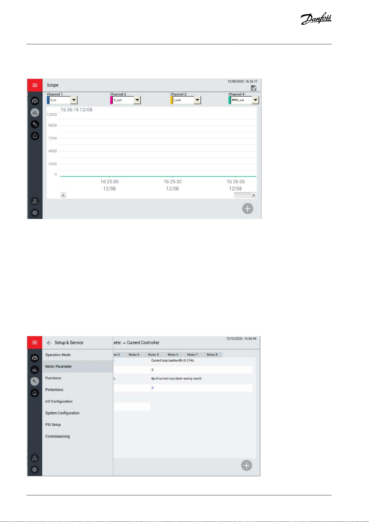
e30bi735.10
e30bi739.10
VACON® 1000
Operating Guide
•
Speed command
•
Input power
Human-Machine Interface
Illustration 58: Graphs & Reports Submenu
7.6 Setup & Service
The Setup & Service button in the HMI menu opens a submenu with the following system function settings:
•
Operation mode
•
Motor parameter
•
Functions
•
Protections
•
I/O configuration
•
System configuration
•
PID setup
•
Commissioning
Illustration 59: Setup & Service Submenu
AQ363633621020en-000201 / 172F311766 | Danfoss A/S © 2021.06
Page 67

e30bi740.10
VACON® 1000
Operating Guide
Human-Machine Interface
7.6.1 Operation Mode
Use this submenu to select the operation mode and the reference set.
Operation mode options:
•
HMI: The drive is operated by HMI.
•
Digital: The drive is operated by DCS (the remote digital control of the drive, see 6.9.4 Application Wiring Example for the specific interface definition).
•
Communication: The drive is operated by communication, such as RS485 or Ethernet.
Reference set options:
•
HMI: Speed is set by HMI.
•
Analog: Speed is set by analog input.
•
Digital: Speed is set by DCS (the remote digital control of the drive, see 6.9.4 Application Wiring Example for the specific interface definition).
•
Communication: Speed is set by communication, such as RS485 or Ethernet.
•
PID: Speed is adjusted automatically by PID module.
Illustration 60: Operation Mode Submenu
7.6.2 Motor Parameter
Use this submenu to select the motor parameters:
•
Multi-motor configuration
-
Select different motors through HMI, digital input, or communication.
-
Set the maximum number of motors.
•
Rated parameter
-
Set the rated frequency, rated speed, pole number, rated voltage, and rated current for different motors.
•
Speed operation configuration
-
Set the rotation direction, maximum speed, and minimum speed for different motors.
•
Auto tuning parameter
-
Check the parameters regarding auto tuning.
•
Speed controller
•
Flux controller
AQ363633621020en-000201 / 172F3117 | 67Danfoss A/S © 2021.06
Page 68

VACON® 1000
Operating Guide
•
Current controller
•
Encoder
-
Input the specifications of the encoder for each motor.
Human-Machine Interface
7.6.3 Functions
Use this submenu to set the parameters for different functions. The parameters are divided into groups according to the functions.
7.6.4 Protections
Use this submenu to set the parameters for different protection functions. The parameters are divided into groups according to the
protection functions.
7.6.5 PID Setup
Use this submenu to set the PID parameters.
•
Analog Input Range: The range of the sensor.
•
Proportional Gain (Kp): The magnified proportional value of the SV-PV error.
-
Unit: %
-
Set range: 0–30000
•
Integral Gain (Ki): The magnified proportional value of an accumulation of each sampling time unit times the error value.
-
Unit: %
-
Set range: 0–30000
•
Differential Gain (Kd): The magnified proportional value of an error variable of each sampling time unit.
-
Unit: %
-
Set range: 0–30000
•
Upper Limit: If the upper limit is 900 RPM, the PID output stays at 900 RPM when the adjusting output value is above 900 RPM.
•
Lower Limit: If the lower limit is 300 RPM, the PID output stays at 300 RPM when the adjusting output value is below 300 RPM.
•
Error Band: The error band value is equal to the SV-PV deviation. If the difference between SV and PV is smaller than the error
band, PID stops output and the drive maintains the current output speed.
•
PID Output: The display of the actual PID output results.
•
SV: The expected values of the user set.
•
PV: The real value of the system output.
•
Output Enable/Disable switch
•
Start/Stop switch
AQ363633621020en-000201 / 172F311768 | Danfoss A/S © 2021.06
Page 69

e30bj288.10
VACON® 1000
Operating Guide
Illustration 61: PID Setup Submenu
Human-Machine Interface
7.6.6 System Configuration
Use this submenu to set the system configuration parameters. The parameters are divided into groups according to the functions.
7.7 Events
Two submenus can be accessed by pushing the Events button in the HMI menu:
•
Warning & Fault
•
Event Log
7.7.1 Warning & Fault
The warning & fault submenu lists the real-time alarm and fault record of the drive during operation.
There are 2 different types of notification.
•
An alarm informs of unusual operation on the drive. The alarm does not stop the drive. The system can be powered on, started,
and operated normally.
•
A fault stops the drive immediately. Reset the drive and find a solution to the problem. Do not operate the system until the
problem has been found and corrected.
This page only shows general faults. To check the actual faults, see the "Event Log".
AQ363633621020en-000201 / 172F3117 | 69Danfoss A/S © 2021.06
Page 70
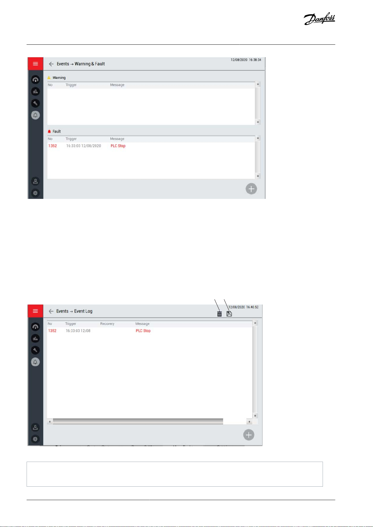
e30bi737.10
BA
e30bi738.10
A
Delete event log
B
Save event log
VACON® 1000
Operating Guide
Illustration 62: Warning & Fault Submenu
Human-Machine Interface
7.7.2 Event Log
The event log submenu shows a record of all:
•
Alarms
•
Faults
•
Operations (for example, starting and stopping the drive)
To save the event log, push the Save button in the upper right corner. The event log information is saved as a CSV-file to a USB
storage device, which must be inserted separately. The USB port is at the back side of the HMI.
To delete the event log, push the Delete button in the upper right corner. This operation needs higher operation authority.
Illustration 63: Event Log Submenu
AQ363633621020en-000201 / 172F311770 | Danfoss A/S © 2021.06
Page 71

e30bi742.10
e30bi743.10
VACON® 1000
Operating Guide
7.8 Administration
Use the Administration submenu for password management. Two actions can be done in this submenu:
•
Relogin
•
Change password
Human-Machine Interface
Illustration 64: Administration Submenu
To bring up the password dialog box, press the Relogin button. If the password input is incorrect, the dialog box remains until the
password input is correct. The original password is provided in the product delivery.
Illustration 65: Password Dialog Box
VACON® 1000 has 3 user authority levels. To prevent malfunctions, the drive restricts important parameter changes by users without authorization.
•
Level 1 authority limits operation to the buttons in the main interface. Parameter changes are not allowed.
•
Level 2 authority limits operation to the buttons in the main interface, and changes to level 2 parameters.
•
Level 3 authority limits operation to the buttons in the main interface, and changes to level 2 and 3 parameters.
To change the password, press the Change button. Users at a higher authority level can see and change the password of the user at
a lower level.
Users at different levels can carry on corresponding operation on the system after entering the correct password. If the user forgets
to exit the loading manually, the system is locked automatically in 5 minutes.
The required passwords are delivered during the commissioning of the drive.
If a password is lost, contact Danfoss.
AQ363633621020en-000201 / 172F3117 | 71Danfoss A/S © 2021.06
Page 72

e30bi741.10
VACON® 1000
Operating Guide
7.9 Tool Settings
The tool settings submenu includes settings for the HMI.
•
Language setting
•
Software version
•
HMI set
7.9.1 Language
Select the language of the HMI according to requirements.
Human-Machine Interface
Illustration 66: Language Submenu
7.9.2 Software Version
This menu shows the software version information for the HMI, PLC, and DSP. Also the power cell version and optical fiber board
version are available.
7.9.3 HMI Set
To adjust the brightness of the HMI screen, select Brightness.
To adjust the date and time setting, select Date/Time.
AQ363633621020en-000201 / 172F311772 | Danfoss A/S © 2021.06
Page 73

e30bi756.10
VACON® 1000
Operating Guide
Illustration 67: HMI Set Submenu
Human-Machine Interface
AQ363633621020en-000201 / 172F3117 | 73Danfoss A/S © 2021.06
Page 74

VACON® 1000
Operating Guide
Commissioning
8 Commissioning
8.1 Safety Checks before Starting the Commissioning
Only qualified and trained engineers authorized by Danfoss are allowed to do the commissioning of the VACON® 1000 mediumvoltage drive.
Functional tests, commissioning, and primary parameter calibration must be executed by professional engineers in coordination
with the end users to make sure that the final test and performance are according to the end users requirements.
Before starting the commissioning, read these warnings.
D A N G E R
SHOCK HAZARD FROM POWER UNIT COMPONENTS
The power unit components are live when the drive is connected to mains. A contact with this voltage can lead to death or seri-
ous injury.
Do not touch the components of the power unit when the drive is connected to mains. Before connecting the drive to mains,
-
make sure that the covers of the drive are closed.
D A N G E R
SHOCK HAZARD FROM TERMINALS
The motor terminals U, V, W are live when the drive is connected to mains, also when the motor does not operate. A contact with
this voltage can lead to death or serious injury.
Do not touch the motor terminals U, V, W when the drive is connected to mains. Before connecting the drive to mains, make
-
sure that the covers of the drive are closed.
D A N G E R
SHOCK HAZARD FROM DC LINK OR EXTERNAL SOURCE
The terminal connections and the components of the drive can be live several minutes after the drive is disconnected from the
mains and the motor has stopped. The load side of the drive can also generate voltage. A contact with this voltage can lead to
death or serious injury.
Disconnect the drive from the mains and make sure that the motor has stopped.
-
Disconnect the motor.
Lock out and tag out the power source to the drive.
Make sure that no external source generates unintended voltage during work.
To ground the drive input and DC link, close the grounding switch. If there is no grounding switch, make sure that the drive
input and DC link are grounded for work. Also ground the motor terminals for work.
Wait for the DC-link capacitors to discharge fully before opening the cabinet door or the cover of the AC drive.
Use a measuring device to make sure that there is no voltage.
8.2 Personnel Requirements
At least two professional electrical technicians are necessary as the operators for commissioning. The operators must meet the following conditions.
•
Must be familiar with the low, medium, and high-voltage electrical equipment and the related safety regulations.
•
Must be familiar with the distribution system on site.
•
Must be authorized to operate low and medium-voltage equipment (high-voltage power breaker and other medium and lowvoltage transmission switches).
•
Must be authorized to operate the distribution equipment in the premises.
8.3 Commissioning Checks
After the VACON® 1000 is installed, follow these instructions to commission the AC drive.
Read the safety instructions in
8.1 Safety Checks before Starting the Commissioning and obey them.
AQ363633621020en-000201 / 172F311774 | Danfoss A/S © 2021.06
Page 75

VACON® 1000
Operating Guide
Visual inspection
Input and output inspection
Cabling inspection
Grounding inspection
Insulation inspection
Other preparations
1.
Check that there is no damage, deformation, or other defects on the cabinet.
2.
Open the controller cabinet door and check for problems such as loose wires or switches in the wrong position.
3.
Check that the terminal boards on the main control box are in the right positions.
4.
Check that the optical fiber connections are in good condition.
5.
Open the transformer cabinet and check that the connections of the wiring terminals are in good condition.
6.
Make sure that there is no contact between the high and low-voltage circuits.
7.
Check that the temperature sensor installation is in good condition.
8.
Open the power cell cabinet and check that the connections in the front of the power cell are solid.
9.
Check that the installation of the voltage and current sensors is correct and that the jacks of the signal wires are firmly
connected.
10.
Check that the grounding copper busbars are connected reliably.
11.
Make sure that there is no condensation on the surfaces of the AC drive.
12.
Make sure that there are no unwanted objects in the installation space.
13.
Check that the input power of the drive meets the drive specification.
14.
Check that the output voltage of the drive matches the rated voltage of the motor.
15.
Check that the control power supply matches the drive specification.
16.
Check that the rated power of the drive matches the motor specification.
17.
Check that the secondary transformer wiring is correct according to the secondary wiring diagram.
18.
Check that the primary wiring is correct according to the primary wiring diagram.
19.
Make sure that the motor cable shield is grounded at the drive and motor ends of the cable.
20.
Make sure that the control cables are as far as possible from the power cables.
21.
Make sure that the cables do not touch the electrical components of the drive.
22.
Do a check of the tightening torques of all the terminals.
23.
Make sure that the AC drive and the motor are grounded.
24.
Make sure that the shields of the shielded cables are connected to a grounding terminal that is identified with the grounding symbol.
25.
Check that the resistances of the grounding copper busbars match the requirements.
Commissioning
•
Control system grounding: ≤0.5 Ω
•
System safety grounding: ≤0.5 Ω
•
Machine cabinet support: ≤0.5 Ω
•
Transformer support: ≤0.5 Ω
•
External housing of the cooling fans: ≤0.5 Ω
•
Door locks: ≤0.5 Ω
26.
Check that all cables meet the requirements.
See 6.7 Power Cable Selection.
27.
Do an insulation test for the control power.
a.
Disconnect the control power input.
b.
Measure the insulation resistance of the 220 V AC terminal at the outgoing parts of the bypass switches QF11,
QF12, and QF13.
Use a 2500 V insulation resistance tester.
The insulation resistance must be higher than 1 MΩ.
28.
Provide an auxiliary AC supply.
29.
Make sure that the installation follows EMC guidelines.
AQ363633621020en-000201 / 172F3117 | 75Danfoss A/S © 2021.06
Page 76

VACON® 1000
Operating Guide
30.
Do a check of the quality and quantity of the cooling air.
31.
Before connecting the drive to the mains, do a check of the installation and the condition of all the protective devices.
32.
Collect all the necessary device instruction manuals, drawings, and materials, and save them.
Commissioning
8.4 Commissioning Report
After the commissioning is finished, the user and the commissioning engineer from Danfoss must accept and sign the commissioning report. The Danfoss commissioning engineer must write two duplicate commissioning reports, one copy is for the user and the
other for Danfoss.
8.5 Operating the Drive
8.5.1 Powering the Drive
Only personnel who have been trained professionally can operate the VACON® 1000 medium-voltage drive.
Procedure
1.
Switch on the auxiliary control supply.
2.
Input the correct password to the HMI.
3.
Set and check the system function and start-up parameters.
See the VACON® 1000 Application Guide.
C A U T I O N
To ensure the safety and normal operation of the drive, the important parameters must be confirmed carefully.
-
4.
Close all cabinet doors.
All the cabinet doors must be closed reliably, otherwise the drive does not start.
5.
If a bypass cabinet is configured, check the main circuit configuration.
a.
Close the input isolation switch.
b.
Close the output isolation switch.
Live operation of the knife gate isolation switch is prohibited.
6.
Check that the VACON® 1000 is ready.
a.
The HMI display is normal, and no failure warning information is shown.
If a warning is shown, see 10 Fault Tracing.
b.
The “MCB close allowed” indicator in the VACON® 1000 status interface blinks.
7.
Close the high voltage breaker.
The “MCB closed” indicator in the VACON® 1000 status interface blinks.
The VACON® 1000 is ready, and the “Start-up ready” indicator in the status interface blinks.
8.
8.5.2 Starting the Drive
The steps for starting the VACON® 1000 depend on the operation mode and reference mode.
Make sure that it is safe to start the motor.
Procedure
1.
Set the speed.
-
HMI: Input the reference speed in the HMI.
-
Analog: Input the speed setting through the analog input.
-
Digital: Input the speed setting through DCS digital signal.
-
Communication: Input the speed setting through communication.
-
PID: Input PID reference value.
AQ363633621020en-000201 / 172F311776 | Danfoss A/S © 2021.06
Page 77

VACON® 1000
Operating Guide
2.
Send the start command.
-
HMI: Press the START button.
-
Digital: Start the equipment through DCS digital signal.
-
Communication: Start the drive through communication.
Commissioning
8.5.3 Stopping the Drive
The procedure for stopping the drive depends on the selected operation mode.
•
HMI: In the control panel, select Ramp or Coast, and press the STOP button. The drive stops according to the corresponding stop
mode, while the main circuit breaker is still closed.
•
Digital: Stop the drive through DCS digital signal.
•
Communication: Stop the drive through communication.
Two different stop modes are possible: Ramp stop and coast stop.
Ramp stop
The drive stops the motor according to the preset deceleration time. For setting the decelerated stop time, see the VACON®
•
1000 Application Guide.
Coast stop
The drive stops the voltage output, and the motor rotates freely and decelerates gradually through the load and friction until it
•
stops.
Consider carefully according to the operation condition whether the motor is allowed to stop freely.
•
D A N G E R
SHOCK HAZARD
During a coast stop, there can still be voltage in the motor cables due to the back EMF generated by the motor. Contact with this
voltage can lead to death or serious injury.
Do not touch the motor terminals or cables when the drive is connected to mains.
-
8.5.4 Powering Off the Drive
D A N G E R
SHOCK HAZARD
The terminals and the components of the drive can be live several minutes after the drive is disconnected from the mains and the
motor has stopped. The load side of the drive can also generate voltage. A contact with this voltage can lead to death or serious
injury.
Keep the cabinet doors closed for 15 minutes after the high voltage is cut off.
-
Procedure
1.
Stop the drive. See 8.5.3 Stopping the Drive.
2.
Command the input high-voltage breaker to open.
3.
If a bypass cabinet is installed, disconnect the input and output isolation switch.
4.
After the power cells finish discharging, power off the control power.
C A U T I O N
Do not cut off the control power when the drive is powered on or the LED indicators of the power cells are on.
-
AQ363633621020en-000201 / 172F3117 | 77Danfoss A/S © 2021.06
Page 78

A
e30bi797.10
B
A
Main key
B
Door keys
VACON® 1000
Operating Guide
Commissioning
8.6 Interlocking System
8.6.1 Electromagnetic Interlocking System
N O T I C E
The electromagnetic interlocking system is installed as standard in IEC type drives.
The electromagnetic interlocking system ensures that the cabinet doors cannot be opened during operation of the drive.
Operation of the electromagnetic interlocking system
•
Before HV power on: All electromagnetic locks are energized, all doors are unlocked, and can be opened or closed. Only after all
doors are closed, and after self-diagnosis, the PLC can send out the "MCB closing allowed" signal.
•
HV power on: Once the MCB is closed to power the drive, the electromagnetic locks are de-energized, the doors are locked, and
cannot be opened during operation of the drive. If the doors are opened despite the locking (for example, by force), an "MCB
trip" signal is immediately sent to trip the MCB.
•
HV power off: After the drive is powered off and the power cell discharge process is completed (15 minutes), the electromagnetic locks are energized, the doors are unlocked, and can be opened.
8.6.2 Mechanical Interlocking System
N O T I C E
The mechanical interlocking system is installed as standard in UL type drives. It is available as an option for IEC variants.
The interlock system ensures that a process is followed and cannot be circumvented or short cut. The transfer of a key ensures that
wherever personnel find themselves, in either starting or shutting down operations, they can be assured that they are safe.
The interlock device contains three main parts:
•
Main key for the isolating means (only one)
•
Door keys (one for each cabinet door)
•
Key exchange box
Illustration 68: Key Exchange Box
Operation of the interlock system
•
While the main key for the isolating means is free from the key exchange box, the other door keys are locked in the box.
•
To release the door keys sequentially, insert and turn the main key in the key exchange box. The released keys can then be used
to open the cabinet doors and to access the hazardous areas.
•
The inserted main key stays locked in the key exchange box until all the released door keys are returned to their original positions.
•
The drive cannot be restarted until all the door keys are returned to the key exchange box and the main key is removed and
taken to the isolating means.
AQ363633621020en-000201 / 172F311778 | Danfoss A/S © 2021.06
Page 79

VACON® 1000
Operating Guide
Maintenance
9 Maintenance
9.1 Safety
C A U T I O N
Only authorized trained personnel can conduct service on the VACON® 1000 medium-voltage drive.
Do not conduct any service, spare parts replacements, or other related operations which are not described in this manual.
-
Do not revise the system software or connect other equipment with the drive. If changes are required, contact Danfoss.
Do not modify or scratch the labels and markings of the drive, as these are provided for the safety of the users and for the use
of the product.
D A N G E R
SHOCK HAZARD FROM DC LINK OR EXTERNAL SOURCE
The terminal connections and the components of the drive can be live several minutes after the drive is disconnected from the
mains and the motor has stopped. The load side of the drive can also generate voltage. A contact with this voltage can lead to
death or serious injury.
Do not do touch the main circuit of the drive or the motor before the system is powered off and grounded.
-
Disconnect the drive from the mains and make sure that the motor has stopped.
Disconnect the motor.
Lock out and tag out the power source to the drive.
Make sure that no external source generates unintended voltage during work.
Ground the drive for work.
Wait 15 minutes for the DC-link capacitors to discharge fully before opening the cabinet door or the cover of the AC drive.
Use a measuring device to make sure that there is no voltage.
W A R N I N G
SHOCK HAZARD
Output voltage detection signals are wired from the voltage divider board to the AD board in the control unit. If any of these
wires are disconnected while MV power is on, a transient high voltage is generated.
Do not disconnect any wires from the AD board terminals while MV power is on.
-
•
More than one disconnect switch can be required to de-energize the equipment before maintenance.
•
Low-voltage fuses that are accessible with the control transformer can be energized. Cut off the supply to the control transformer before replacing the fuses.
•
There are bulk DC-link capacitors in the drive, which must be discharged to a level below 50 V DC for safe maintenance work.
•
The socket in the control cabinet is only for maintaining or repairing equipment. The current rating is 10 A. Any equipment with
rated current larger than 10 A is prohibited. This equipment does not provide isolation. Separate isolating means are required.
-
The isolating means listed in Table 9 or equivalent can be used.
AQ363633621020en-000201 / 172F3117 | 79Danfoss A/S © 2021.06
Page 80

Type of isolating means
Manufacturer
Model name
Rating
Medium-voltage controller
ROCKWELL AUTOMATION CANADA INC
(E102991)
1512A-1
400 A/7.2 kV
Medium-voltage switchgear
ABB INC POWER TECHNOLOGY PRODUCTS
MEDIUM VOLTAGE (E143324)
ADVANCE Series
3000 A/ 1000 MVA/
27 kV max.
SAFEGEAR Series
4000 A/1000 MVA/
15 KV
Circuit breakers and metal-clad
switchgear
EATON (E146558)
VC-W series
3000 A/15 kV max.
Maintenance item
Maintenance interval
Maintenance task
Environment
Daily
Check that the temperature inside the drive cabinets is -5...+40°C, preferably 25°C.
Check that humidity is below 95% and that there is no condensation.
VACON® 1000
Operating Guide
Table 9: Recommended Isolating Means
9.2 Standard Maintenance Process
To ensure safe maintenance, follow the described steps.
Procedure
1.
Familiarize with the safety measures and cautions described in this manual, and obey them.
2.
Cut off the system power and shut down the UPS. If a bypass cabinet is installed, cut off the power of the bypass cabinet.
All maintenance tasks must be conducted with the mains and auxiliary power disconnected.
Maintenance
3.
Conduct the necessary maintenance.
Refer to the maintenance plan and the specific instructions.
4.
After maintenance, check before power-on.
a.
Make sure that the connections to the mains and the motor are in good condition.
b.
Make sure that the connections to the auxiliary power and the control circuit are in good condition.
c.
Make sure that no tools or foreign objects are left in the cabinets.
d.
Make sure that all the cabinet doors including protective isolation facilities are closed and ready in position.
5.
Restart the drive. Follow the instructions in 8.5.1 Powering the Drive and make sure that there is nothing abnormal in the
operation.
6.
Make a record of the maintenance done to the VACON® 1000 drive.
The maintenance record must include:
•
The date and time.
•
The maintenance actions performed according to the maintenance plan.
•
Any special situation or work (planned or unplanned spare parts replacement).
9.3 Maintenance Schedule
To ensure the long-term steady operation of the equipment, conduct correct operation and maintenance. The daily protective
maintenance and inspections must be conducted in a planned way. In addition to the emergency system maintenance, predictive
maintenance must be conducted, including daily, weekly, monthly, quarterly, and annual inspections and maintenance.
The daily maintenance tasks are limited to various visual inspections, air filter cleaning, and keeping the installation room as clean
as possible. Other maintenance tasks are only allowed for authorized trained personnel.
9.3.1 Daily Maintenance
Table 10: Daily Maintenance Tasks
AQ363633621020en-000201 / 172F311780 | Danfoss A/S © 2021.06
Page 81

Maintenance item
Maintenance interval
Maintenance task
Check the condition of the ventilation and air ducts.
Record the environment parameters daily, and note if there are abnormal conditions.
Operating
parameters
Daily
Check that the drive input voltage is correct.
Check that the drive operating parameters are normal.
Check the drive for warnings/faults.
Check the indicator lights of the drive.
Check that the temperature of the transformer, shown on HMI, is below 90°C.
Check that there is no abnormal sound, vibration, fire, or smell.
Cooling fans
Daily
Check that there is no abnormal vibration or sound.
Check that there are no cooling fan overtemperature or cooling fan power supply drop alarms.
Air filters
Daily
Check that the air filters are not blocked.
Check that there is no air pressure alarm.
Weekly
Clean the filters at least once a week. If the dust is heavy, the cleaning interval must be shorter.
To remove dust, gently tap the filters or blow slightly with compressed air outside the electrical
room.
To remove caked on dirt, rinse the filters with water and a gentle detergent. Dry the filters before
installing back on the drive.
If necessary, replace the filters with new ones.
Drive room
Daily
Check the drive room daily. Remove any foreign items.
Weekly
Clean the drive room once a week. Use a vacuum cleaner or mop to clean any dust or ash.
Maintenance
item
Maintenance
interval
Maintenance task
Cabling
Yearly
Check the tightening torques of the terminals.
Check that the insulation layer of cables is not damaged.
Check the grounding.
Transformer
Yearly
Measure the insulation resistance between primary/secondary to ground.
Every 2 years
Perform dielectric withstand tests between primary/secondary to ground.
Drive cabinets
Yearly
Clean inside the drive cabinets with a vacuum cleaner.
Clean the dust on the surface of components, and clean the dust in the heat sinks of power
cells.
Components
Yearly
Use a multimeter to check that the output voltage of power supply in control cabinet is
26±0.5 V DC.
Check that the output voltage of the UPS is 25±0.5 V DC.
Check that the relay works normally and there is no abnormal sound.
Check that the indicators work normally.
Check that the electromagnetic interlocks work normally.
VACON® 1000
Operating Guide
Maintenance
9.3.2 Yearly Maintenance
Table 11: Yearly Maintenance Tasks
AQ363633621020en-000201 / 172F3117 | 81Danfoss A/S © 2021.06
Page 82

Maintenance
item
Maintenance
interval
Maintenance task
Check the heater and humidistat. Set the threshold of the humidistat below the ambient humidity and check that the heater starts working. After testing, set the threshold to 80%.
Check the high voltage electric display light and that the second locked circuit is normal.
Check that the thermal relay setting value is correct.
Do a close test for the vacuum contactor or breaker, and check that the operation and feed-
back status is correct.
Check that the fuse and breaker is normal and there are no burn marks.
UPS battery
Every 3 years
Change the battery every 3 years for reliable operation.
Every 3 months
If the drive is stored for over 3 months and is not turned on during that time, charge the UPS
battery for 8 hours.
Charge spare storage batteries every 3 months.
HMI
Depending on
condition
The brightness of the HMI decays over time. The lifetime depends on the use conditions.
High voltage
electric display
device
Every 4 years
Change every 4 years for reliable operation.
Cooling fan
Every 4 years
Change every 4 years.
Indicator
Every 5 years
Change every 5 years.
Switching
power supply
Every 10 years
Change every 10 years.
Power cells
1 year
If a stored power cell has not been energized in the last 1 year, the electrolytic capacitors
must be reformed.
If the drive is stored for more than 2 years, high voltage cannot be applied directly to the
drive. Raise the input voltage gradually to wait until the capacitors are charged properly.
e30bi682.10
A
B
A
Screws
VACON® 1000
Operating Guide
Maintenance
9.4 Replacing the Air Filters
9.4.1 Air Filters of Standalone Cabinets
Procedure
1.
Loosen the screws on the air filter cover.
Illustration 69: Releasing the Filter Cover
AQ363633621020en-000201 / 172F311782 | Danfoss A/S © 2021.06
Page 83

B
Filter cover
e30bi683.10
e30bi684.10
A
A
Air filter
e30bi685.10
A
B
C
VACON® 1000
Operating Guide
2.
Remove the air filter cover.
Illustration 70: Removing the Filter Cover
3.
Remove the filter and replace it with a new one.
Maintenance
Illustration 71: Replacing the Air Filter
4.
Reinstall the filter cover and tighten the screws.
5.
Note the filter replacement date.
9.4.2 Air Filters of Transformer and Power Cell Cabinets
Procedure
1.
Loosen the screws on the air filter cover.
Illustration 72: Air Filter Replacement
AQ363633621020en-000201 / 172F3117 | 83Danfoss A/S © 2021.06
Page 84

A
Screws
B
Filter cover
C
Air filter
e30bi686.10
1
2
1
Filter cover
2
Air filter
A
A
e30bi723.10
A
Cover mounting screws
VACON® 1000
Operating Guide
2.
Remove the air filter cover and remove the old filter.
3.
Install a new air filter in place of the old one.
4.
Reinstall the filter cover and tighten the screws.
5.
Note the filter replacement date.
9.4.3 Air Filters of Control Cabinet
Procedure
1.
Press the button and pull back the top part of the filter cover.
Maintenance
Illustration 73: Releasing the Filter Cover
2.
Remove the air filter cover.
3.
Remove the filter and replace it with a new one.
4.
Reinstall the filter cover.
5.
Note the filter replacement date.
9.5 Replacing the HMI Battery
Procedure
1.
Remove the screws at the back side of the HMI.
Illustration 74: Locations of the HMI Cover Mounting Screws
AQ363633621020en-000201 / 172F311784 | Danfoss A/S © 2021.06
Page 85

e30bi724.10
VACON® 1000
Operating Guide
2.
Open the HMI back cover plate.
3.
Replace the battery.
The HMI uses a 3 V lithium battery, type CR2032×1.
Illustration 75: Location of the Battery Inside the HMI
9.6 Replacing the Cooling Fans
Cut off the system power according to 9.2 Standard Maintenance Process and take all the safety measures.
N O T I C E
The cooling fans have different models according to power levels.
Maintenance
Procedure
1.
If an air duct is used to exhaust hot air outside the installation room, disassemble the interface between the air duct and the
cooling fan.
2.
Remove the front and back grates (A). Each is mounted with 9 M6x16 hexagonal combination screws. Retain the screws.
3.
Remove the cooling fan cover (B). Remove and retain 16 M4x8 countersunk head screws.
4.
Remove the bottom grate (C). Remove and retain ten M6x16 hexagonal combination screws.
5.
Remove the wiring cover and disconnect the fan wiring.
6.
Remove the fan bracket (D). Remove and retain 8 M8x20 hexagonal combination screws.
7.
Remove the fan (E). Remove and retain 5 M6x16 and 4 M4x12 hexagonal combination screws.
8.
Install the new fan and fasten all screws in reverse sequence.
9.
Finish up the maintenance and replacement by reinstalling the parts in reverse order.
10.
If there is an air duct, restore and fix the interface of the air duct.
9.6.1 Diagram of the Cooling Fan Replacement.
See
The bottom grate is only available in optional configurations.
Finish the installation of the fan power and cable interface before fastening the cooling fan mounting screws.
AQ363633621020en-000201 / 172F3117 | 85Danfoss A/S © 2021.06
Page 86

e30bi672.10
M4×12
A
E
D
B
M8×20
M4×8
M6×16
M6×16
C
M6×16
M6×16
A
Front and back grates
B
Cooling fan cover
C
Bottom grate
D
Fan bracket
E
Cooling fan
VACON® 1000
Operating Guide
11.
Check that the fan is in normal operation after power-on. Pay special attention to the rotation direction of the fan. The fan
must suck air from the inlet window frame and blow air outwards from the top of the cabinet.
9.6.1 Diagram of the Cooling Fan Replacement
Maintenance
Illustration 76: Cooling Fan Replacement
9.7 UPS Battery
9.7.1 Replacing the UPS Battery
Procedure
1.
Switch off QF15.
2.
Remove the cover of the UPS battery. The cover is mounted with 4 screws.
3.
Disconnect the wires from the battery terminals.
4.
Install the new UPS battery and reconnect the wires.
Note the polarity of the battery, and make sure that the wires are connected correctly.
9.7.2 UPS Battery Maintenance
If the UPS battery is not used in the long term, a scheduled periodical maintenance of the battery is highly recommended.
AQ363633621020en-000201 / 172F311786 | Danfoss A/S © 2021.06
Page 87

Storage temperature
Maintenance interval
<20ºC
Every six months
20–30ºC
Every three months
>30ºC
Storage above this temperature in the long term is strictly forbidden.
+
-
e30bi754.10
R
S
T
A
B
C
Power
Current-limiting resistors
e30bi720.10
VACON® 1000
Operating Guide
Table 12: Maintenance Schedule
A power supply with a tunable DC output and an output current limit function, is required for the maintenance.
Procedure
1.
Tune the output voltage of the DC power to 14.4–14.7 V.
2.
Set the output current limit to 1.3 A.
3.
Connect the positive/negative poles of the DC power to the correspondent sides of the battery.
Maintenance
Illustration 77: UPS Battery Terminals
4.
Switch on the DC power to charge the battery.
5.
Charge each battery for at least 16–24 hours.
6.
After charging, cut off the DC power and disconnect the wires between UPS battery and DC power.
9.8 Power Cells
9.8.1 Power Cell Maintenance
Procedure
1.
Take the power cell out of the drive cabinet, or if in storage, out of its insulated plastic bag.
2.
Place the power cell on an insulated location.
The withstand voltage level must exceed the input power.
3.
Connect a 3-phase power to the power cell input terminals though a 3-phase current-limiting resistor.
Different power cells have different mechanical designs.
Connect to the hung-up side of the fuses.
Illustration 78: Power Cell Circuit Diagram
AQ363633621020en-000201 / 172F3117 | 87Danfoss A/S © 2021.06
Page 88

A
B
C
e30bi721.10
e30bi722.10
VACON® 1000
Operating Guide
Illustration 79: Power Cell Input Terminals A, B, C
4.
Power up the power cell and check the indicator lights on the power cell.
Maintenance
Illustration 80: Power Cell Indicator Locations
The status of the power cell is normal if the indicators PWR and COM are on.
If any other LED indicators are on, further inspection is necessary. Contact Danfoss.
5.
Keep the power cell powered up for one hour.
If after one hour there is nothing abnormal shown by the power cell indicators, the maintenance is done.
6.
Turn off the power and remove the connections.
7.
Put power cell back in the drive cabinet, or if stored, in its insulated plastic bag.
8.
If there are any problems, contact Danfoss.
9.8.2 Replacing the Power Cells
Cut off the system power according to 9.2 Standard Maintenance Process and take all the safety measures.
Procedure
1.
Disconnect the fiber optical wiring (A) from the power cell.
See 9.8.2.1 Diagram of the Power Cell Replacement.
2.
Remove the combination screws from the interconnection busbars (B) on the two sides of the power cells. Retain the
screws carefully.
Use an M6/M8 torque sleeve wrench.
AQ363633621020en-000201 / 172F311788 | Danfoss A/S © 2021.06
Page 89

e30bi755.10
A
B
C
D
D
D
D
E
VACON® 1000
Operating Guide
3.
Remove the fixed screws on the 3-phase input terminals (C). Retain the screws carefully.
Use an M8/M10 torque sleeve wrench.
4.
To release the power cell from the brackets (D), remove the screws in front of the power cell. Save the screws carefully.
Use an M6 torque wrench.
5.
Pull out the power cell along the guide rails (E).
6.
Check the nameplate of each power cell. Confirm that the nameplate of the new power cell matches the old one.
7.
Push the new power cell into place on along the guide rail.
8.
Mount the power cell on the brackets.
Use an M6 torque wrench to install the screws. Tighten the screws to torque 9.8±0.2 Nm.
9.
Mount the 3-phase input cables on the power cell terminals.
Use an M8/M10 torque sleeve wrench. The fixing order from outside to inside is flat washer, spring washer, screw nut.
Tightening torques:
•
M8 screws: 9.8±0.2 Nm.
•
M10 screws: 24.5±0.5 Nm.
10.
Mount the combination screws on the interconnection busbars.
Use an M6/M8 torque sleeve wrench.
Tightening torques:
•
M6 screws: 7.8±0.2 Nm.
•
M8 screws: 9.8±0.2 Nm.
Maintenance
11.
Connect the fiber optical wiring on the power cell.
9.8.2.1 Diagram of the Power Cell Replacement
Illustration 81: Power Cell Replacement
AQ363633621020en-000201 / 172F3117 | 89Danfoss A/S © 2021.06
Page 90

A
Fiber optic connectors
B
Interconnection busbars
C
Input terminals
D
Bracket
E
Guide rail
Voltage
regulator
Power
cell
MCB
Power
supply
380 V AC
(460 V AC)
e30bi744.10
5 min
10 min
15 min
15 min
t (min)
30%
50%
80%
100%
V (%)
0
e30bi745.10
VACON® 1000
Operating Guide
Maintenance
9.8.3 Reforming the Power Cell Capacitors
If a stored power cell has not been energized in the last 1 year, the electrolytic capacitors must be reformed. The reforming can be
done with an AC or DC supply.
9.8.3.1 Reforming with an AC Supply
Required equipment:
•
Three-phase voltage regulator, 0–750 V AC, ≥500 VA
•
MCB, ≥380 V AC (460 V AC), ≥20 A
C A U T I O N
During the reforming, observe whether there is any abnormal phenomenon. If there is anything abnormal, open the MCB
-
immediately.
Make sure that the wiring for the reforming is done correctly.
Check that the power cell fuses are OK.
If there still are problems, contact Danfoss for assistance.
Procedure
1.
Isolate the power cell from earth ground and separate it from personnel. Make sure that no wires are connected to the
power cell output.
2.
Connect the wires as shown in
the voltage regulator secondary winding to the power cell 3-phase input.
Illustration 82: AC Supply Wiring Diagram
3.
Close the MCB. Turn on the voltage regulator, and bring up the input voltage slowly to 30% of the power cell nominal
voltage (690 V AC). Maintain 30% voltage for 5 minutes.
Illustration 82. Install the MCB between the AC supply and the voltage regulator. Connect
Illustration 83: Reforming Process Diagram
4.
Slowly increase the regulator input voltage to 50%. Maintain the voltage for 10 minutes.
5.
Slowly increase the regulator input voltage to 80%. Maintain the voltage for 15 minutes.
6.
Slowly increase the regulator input voltage to 100%. Maintain the voltage for 15 minutes.
7.
Once the process is complete, decrease the voltage source to zero and open the MCB.
8.
Disconnect the voltage regulator from power cell and AC supply.
AQ363633621020en-000201 / 172F311790 | Danfoss A/S © 2021.06
Page 91

AC
F1
F2
F3
DC
DC
AC
C
Power
supply
Power cell
1000 V DC
e30bi746.10
VACON® 1000
Operating Guide
9.
Wait for 15 minutes for the power cell capacitors to discharge fully.
10.
Use a measuring device to make sure that there is no voltage.
11.
Restore the original wiring.
9.8.3.2 Reforming with a DC Supply
Required equipment:
•
DC supply, 0–1000 V DC adjustable, ≥1000 VA
C A U T I O N
During the reforming, observe whether there is any abnormal phenomenon. If there is anything abnormal, open the MCB
-
immediately.
Make sure that the wiring for the reforming is done correctly.
Check that the power cell fuses are OK.
If there still are problems, contact Danfoss for assistance.
Procedure
1.
Isolate the power cell from earth ground and separate it from personnel. Make sure that no wires are connected to the
power cell output.
2.
Connect the wires as shown in Illustration 84. Connect the DC supply to any 2 of the power cell input phases.
Maintenance
Illustration 84: DC Supply Wiring Diagram
3.
Turn on the DC supply. To prevent DC supply overcurrent protection, step up the input voltage slowly to 30% of the power
cell nominal voltage 975 V DC. Maintain 30% voltage for 5 minutes.
See Illustration 83.
4.
Slowly increase the DC supply input voltage to 50%. Maintain the voltage for 10 minutes.
5.
Slowly increase the DC supply input voltage to 80%. Maintain the voltage for 15 minutes.
6.
Slowly increase the DC supply input voltage to 100%. Maintain the voltage for 15 minutes.
7.
Once the process is complete, decrease the voltage source to zero and turn off the DC suppply.
8.
Disconnect the wires from the power cell and DC supply.
9.
Wait for 15 minutes for the power cell capacitors to discharge fully.
10.
Use a measuring device to make sure that there is no voltage.
11.
Restore the original wiring.
9.9 Dielectric Withstand Test
Procedure
1.
Disconnect the input and output cables.
2.
Short the input terminals (3 phases).
3.
Short the output terminals (3 phases).
4.
Short the transformer auxiliary winding terminals (3 phases) and grounding.
5.
Short all power cell input terminals and output terminals.
6.
If installed, disconnect the neutral grounding resistor connected to power cell U1/V1/W1.
7.
If installed, disconnect the surge arrestor, and the input and output voltage divider from the HV terminal.
8.
Test the input and output voltages.
-
If the input voltage and output voltage ratings are not the same, conduct the dielectric withstand test separately.
AQ363633621020en-000201 / 172F3117 | 91Danfoss A/S © 2021.06
Page 92

System voltage (kV)
Dielectric withstand voltage (kV)
2.3/2.4
839
3.3104/4.16/4.2
12
4.8/5146176.3186.6196.9/7.2
20
8.4221025112711.428122912.47
30
13.23213.8
34
VACON® 1000
Operating Guide
-
If the input voltage and output voltage rating are the same, conduct the dielectric withstand test covering both input
and output.
9.9.1 Testing Input and Output Together
Procedure
1.
Connect the shorted input and output terminals to ground.
2.
Measure the insulation resistance between the input terminals and ground with a 1000 V megohmmeter. The resistance
must be >100 MΩ.
3.
Apply power frequency high voltage at the input terminal referred to ground for 5 s. No breakdown and flashover are required.
4.
Measure the insulation resistance again. The resistance must be >100 MΩ, and the variation must be less than 30% compared with the first measurement result.
5.
After the test, restore the drive to its original state. Restore the wiring connections and remove the shorting.
9.9.2 Testing Input and Output Separately
Procedure
1.
Connect the shorted input and output terminals to ground.
2.
Measure the insulation resistance between the input terminals and ground with a 1000 V megohmmeter. The resistance
must be >100 MΩ.
3.
Apply power frequency high voltage (see table) at the input terminal referred to ground for 60 s. No breakdown and flashover are required.
Maintenance
4.
Measure the insulation resistance again. The resistance must be >100 MΩ, and the variation must be less than 30% compared with the first measurement result.
5.
Disconnect the short circuit wire between the output terminal to ground, and short the input terminal to ground.
6.
Repeat the measurements in steps 2–4 for the output terminals.
AQ363633621020en-000201 / 172F311792 | Danfoss A/S © 2021.06
Page 93

VACON® 1000
Operating Guide
7. After the test, restore the drive to its original state. Restore the wiring connections and remove the shorting.
Maintenance
AQ363633621020en-000201 / 172F3117 | 93Danfoss A/S © 2021.06
Page 94

Configuration value
Detection enable
Alarm/Fault
Action (not running)
Action (running)
0
Disable
–––1Enable
Alarm
No action
No action
2
Enable
Fault
No action
Coast stop
3
Enable
Fault
No action
Coast stop, and bypass system
4
Enable
Fault
No action
Deceleration and stop
5
Enable
Fault
No action
Trip MCB
6
Enable
Fault
No action
Trip MCB, and bypass system
7
Enable
Fault
Trip MCB
Trip MCB
8
Enable
Fault
Trip MCB
Trip MCB, and bypass system
VACON® 1000
Operating Guide
Fault Tracing
10 Fault Tracing
10.1 Fault Types
When the control diagnostics of the drive find an unusual condition in the operation of the drive, the drive shows a notification
about it. The notification can be seen on the display of the control panel. The display shows the number, the name, and a short
description of the fault or alarm.
There are 2 different types of notification.
•
An alarm informs of unusual operation on the drive. The alarm does not stop the drive. The system can be powered on, started,
and operated normally.
•
A fault stops the drive immediately. Reset the drive and find a solution to the problem. Do not operate the system until the
problem has been found and corrected.
It is possible to configure different responses for some faults in the application. See
To view specific information about alarms or faults, click AlarmFault.
Before contacting the distributor or the factory because of unusual operation, prepare some data. Write down the fault number and
all other information on the display.
10.2 Fault Response Configuration
It is possible to configure different responses for some faults in the application. There are 9 valid combinations for alarm and fault
action configuration.
10.2 Fault Response Configuration.
Table 13: Fault Response Configurations for VACON® 1000
10.3 Faults and Alarms
10.3.1 Fault Code 1 - Input Overcurrent (Software Fault)
Cause
The input current is higher than 150% of the rated current.
System default operation: Trip
Troubleshooting
•
Check the input current.
•
Check the set value.
10.3.2 Fault Code 2 - Input Phase Loss
Cause
One or more high-voltage input cables cannot supply primary power to the input transformer.
AQ363633621020en-000201 / 172F311794 | Danfoss A/S © 2021.06
Page 95

VACON® 1000
Operating Guide
System default operation: Trip
Troubleshooting
•
Check the input voltage.
•
Check if the input cables are loose or disconnected.
10.3.3 Fault Code 3 - Input Power Loss
Cause
The voltage values of the 3 input phases are all lower than 70% of the rated value.
System default operation: Trip. System operation is configurable.
Troubleshooting
•
Check the input voltage.
10.3.4 Fault Code 4 - Input Undervoltage
Cause
The effective value of the input voltage is lower than 90% of the rated value.
System default operation: Alarm. System operation is configurable.
Troubleshooting
•
Check the input voltage.
10.3.5 Fault Code 5 - Input Overvoltage
Cause
The effective value of the input voltage is higher than 110% of the rated value.
System default operation: Trip
Troubleshooting
•
Check the input voltage.
Fault Tracing
10.3.6 Fault Code 6 - Input Grounding
Cause
Input grounding occurs, and the duration time is above 5 s.
System default operation: Trip. System operation is configurable.
Troubleshooting
•
Check the input cables, copper busbars, and transformer.
10.3.7 Fault Code 7 - Input Sequence Fault
Cause
The input cables are connected in reverse.
System default operation: Alarm. System operation is configurable.
Troubleshooting
•
Check the sequence of the input cables.
10.3.8 Fault Code 8 - Output Overcurrent (Software Fault)
Cause
The output current is higher than 150% of the rated current.
System default operation: Coast stop. System operation is configurable.
Troubleshooting
•
Check the output current.
•
Check the set value.
10.3.9 Fault Code 9 - Output Overload
Cause
Constant torque: When the output current is higher than 150% of the rated current, allow for 1 minute overload every 10 minutes.
Variable torque: When the output current is higher than 120% of the rated current, allow for 1 minute overload every 10 minutes.
AQ363633621020en-000201 / 172F3117 | 95Danfoss A/S © 2021.06
Page 96

VACON® 1000
Operating Guide
System default operation: Coast stop. System operation is configurable.
Troubleshooting
•
Check the power grid voltage.
•
Reset the rated current of the motor.
•
Check the load and adjust the torque increase.
•
Select proper motor.
10.3.10 Fault Code 10 - Output Phase Loss
Cause
The software detects that the output phase from the drive to motor is disconnected.
System default operation: Coast stop. System operation is configurable.
Troubleshooting
•
Check if the output cables are loose or disconnected.
10.3.11 Fault Code 11 - Output Grounding
Cause
The software detects a grounding fault which is usually caused by an output grounding fault (phase-to-ground fault).
System default operation: Coast stop. System operation is configurable.
Troubleshooting
•
Check that the external cables and the motor are grounded.
•
Check the insulation of the motor and its cables.
Fault Tracing
10.3.12 Fault Code 12 - Output Phase Imbalance Alarm
Cause
During 10 minutes of continuous running time, the output imbalance is above 15‰ for a cumulative time of more than 30 s.
System default operation: Alarm. System operation is configurable.
Troubleshooting
•
Check that the capacitance of the DC-link capacitors matches the specifications.
•
Check that the voltage of the transformer secondary windings is balanced.
10.3.13 Fault Code 13 - Output Phase Imbalance Fault
Cause
The output imbalance is above 30‰ for over 1 s.
System default operation: Coast stop. System operation is configurable.
Troubleshooting
•
Check that the capacitance of the DC-link capacitors matches the specifications.
•
Check that the voltage of the transformer secondary windings is balanced.
10.3.14 Fault Code 14 - Output Underload
Cause
The software detects the motor operating in the underload area for longer than 20 s.
System default operation: Not detected. System operation is configurable.
Troubleshooting
•
Check if the load of motor is too light.
10.3.15 Fault Code 15 - Electronic Motor Thermal Protection
Cause
The calculated temperature or temperature rise is higher than the setting value.
AQ363633621020en-000201 / 172F311796 | Danfoss A/S © 2021.06
Page 97

VACON® 1000
Operating Guide
System default operation: Not detected. System operation is configurable.
Troubleshooting
•
Check if the ambient temperature is high.
•
Check if the load of the motor is heavy.
10.3.16 Fault Code 16 - Motor Stall
Cause
•
The motor frequency/speed is below the set value.
•
A torque limit condition is present.
•
Both conditions occur simultaneously and the duration is above the stall time setting.
System default operation: Not detected. System operation is configurable.
Troubleshooting
•
Check if the motor is overloaded.
•
Check if there is a mechanical failure.
•
Check if there are any other problems which make the motor jam.
10.3.17 Fault Code 17 - Motor Reverse
Cause
The motor is rotating in reverse.
System default operation: Not detected. System operation is configurable.
Troubleshooting
•
Check the motor rotating status.
Fault Tracing
10.3.18 Fault Code 18 - Motor Overspeed
Cause
The speed of the motor is 120% of the maximum operational speed for longer than 10 s.
System default operation: Coast stop. System operation is configurable.
Troubleshooting
•
Check the motor status.
•
Check if the speed encoder is broken.
10.3.19 Fault Code 19 - Motor Underspeed
Cause
The speed of the motor is 6% of the minimum operational speed for longer than 60 s.
System default operation: Not detected. System operation is configurable.
Troubleshooting
•
Check the motor status.
•
Check if the speed encoder is broken.
10.3.20 Fault Code 20 - Analog Reference Loss
Cause
The analog input is disconnected.
System default operation: Alarm. System operation is configurable. The system continues to operate and keeps the last reference
speed.
Troubleshooting
•
Check the analog circuit.
10.3.21 Fault Code 21 - Encoder Abnormal
Cause
The encoder signal is lost or the error between encoder speed and estimated speed is higher than 5%.
AQ363633621020en-000201 / 172F3117 | 97Danfoss A/S © 2021.06
Page 98

VACON® 1000
Operating Guide
System default operation: Coast stop during SVC, not detected during SLVC. System operation is configurable.
Troubleshooting
•
Check if the encoder is operating normally.
10.3.22 Fault Code 22 - Input Overcurrent (Hardware Fault)
Cause
The input current is larger than 210% of the input current sample rating.
System default operation: Trip
Troubleshooting
•
Check the input current.
10.3.23 Fault Code 23 - Output Overcurrent (Hardware Fault)
Cause
The output current is larger than 210% of the output current sample rating.
System default operation: Trip
Troubleshooting
•
Check the output current.
10.3.24 Fault Code 24 - Current Sensor Power Fault
Cause
The LEM power board is not energized.
System default operation: Trip. System operation is configurable.
Troubleshooting
•
Check the supply of the LEM power board.
Fault Tracing
10.3.25 Fault Code 25 - Bypassed Cell Quantity Over Limit
Cause
The quantity of bypassed power cells in one phase is above the setting value.
System default operation: Coast stop
Troubleshooting
•
Check the power cells for faults.
•
Check the quantity of bypassed power cells.
•
Repair or replace the failed power cell.
10.3.26 Fault Code 26 - System Running with MCB Open
Cause
During operation, the MCB status digital input in the main controller I/O board is open.
System default operation: Coast stop
Troubleshooting
•
Check the status of the MCB.
10.3.27 Fault Code 27 - Synchronous Switch Status Error
Cause
KM2 and KM4 are closed at the same time before synchronous transfer start.
System default operation: Trip
Troubleshooting
•
Check the status of switches.
10.3.28 Fault Code 28 - Auto Tuning Failure
Cause
During auto tuning, a fault occurs or a stop command is received.
AQ363633621020en-000201 / 172F311798 | Danfoss A/S © 2021.06
Page 99

VACON® 1000
Operating Guide
System default operation: Coast stop
Troubleshooting
•
Check the fault record.
Fault Tracing
10.3.29 Fault Code 29 - Flying Start Failure
Cause
During flying start, a speed search failure occurs or any other fault is generated.
System default operation: Coast stop
Troubleshooting
•
If a speed search failure caused the flying start failure, check the parameter of the flying start result for the reason for the flying
start failure.
•
If some other fault caused the flying start failure, check the fault record.
10.3.30 Fault Code 30 - Automatic Restart Failure
Cause
During the trial time of the automatic restart, the number of faults is higher than the maximum number of trials, or a permanent
fault occurs.
System default operation: Trip
Troubleshooting
•
Check the fault record.
10.3.31 Fault Code 31 - Synchronous Transfer Failure
Cause
One of the following occurs during synchronous transfer:
•
Switch status/close/open failure.
•
Speed stable timeout. Caused by load fluctuation, which can occur during acceleration to grid frequency in the drive to grid
synchronization process.
•
Voltage synchronous timeout. Caused by electric network fluctuation, which can occur during the voltage synchronization
process.
•
Load transfer timeout. Caused by load fluctuation, which can occur during the load transfer process.
System default operation: Trip
Troubleshooting
•
If there is a switch status/close/open failure:
-
Check the status of the switches.
-
Check the wiring of the digital inputs/outputs.
-
Make sure that there are no problems with the breaker.
•
If there is a speed stable timeout, modify parameter “Speed err threshold of synchronous transfer” (P0772).
•
If there is a voltage synchronous timeout, modify one of these parameters:
-
“Phase error threshold of synchronous transfer” (P0767)
-
“Voltage error threshold of synchronous transfer” (P0771)
-
“Maximum voltage synchronize time of synchronous transfer” (P0778)
•
If there is a load transfer timeout, modify one of these parameters:
-
“Current error threshold of synchronous transfer” (P0353)
-
“Maximum load transfer time of synchronous transfer” (P0779)
10.3.32 Fault Code 32 - Failure Of Motor Selection
Cause
The serial number of selected motor is wrong.
AQ363633621020en-000201 / 172F3117 | 99Danfoss A/S © 2021.06
Page 100

VACON® 1000
Operating Guide
System default operation: Coast stop
Troubleshooting
•
Check if the value of parameter “Motor selection” is larger than parameter “Maximum number of motor”.
•
Check that the motor connected to the drive is the motor specified by parameter “Motor selection”.
10.3.33 Fault Code 33 - LVRT Failure
Cause
One of the following occurs during the low voltage ride through:
•
The duration of power loss is more than 1 s.
•
The DC-capacitor voltage is below 400 V.
•
The motor speed is below 5%.
System default operation: Trip
Troubleshooting
•
Check the parameter “Fault flag of low voltage ride through”.
•
Modify the related parameters according to parameter “Fault flag of low voltage ride through”.
10.3.34 Fault Code 34 - Bypass Derating Failure
Cause
During bypass derating, another power cell bypass occurs.
System default operation: Coast stop
Troubleshooting
•
If the quantity of bypassed power cells is not over the limit, reset and start the system.
•
If the quantity of bypassed power cells is over the limit:
-
Check the fault of the power cell.
-
Check the quantity of the bypassed power cells.
-
Repair or replace the failed power cell.
Fault Tracing
10.3.35 Fault Code 35 - Input Current Sampling Fault
Cause
Input current is out of the current sampling scope.
System default operation: Trip
Troubleshooting
•
Check the input current.
10.3.36 Fault Code 36 - Output Current Sampling Fault
Cause
Output current is out of the current sampling scope.
System default operation: Coast stop. System operation is configurable.
Troubleshooting
•
Check the output current.
10.3.37 Fault Code 37 - Internal Control Power Loss
Cause
The back-up control power provided by the phase-shift transformer auxiliary winding is lost.
System default operation: Alarm
Troubleshooting
•
Check the wiring and voltage of the back-up control power.
•
Check that the corresponding switches are closed.
•
Check that the corresponding relays work normally.
AQ363633621020en-000201 / 172F3117100 | Danfoss A/S © 2021.06
 Loading...