

Page 1

vacon
ac drives
®
opte2/e8
rs485 multiprotocol option board
installation manual
Page 2

Page 3

vacon • 3
TABLE OF CONTENTS
Document: DPD01780C
Release date : 7/1/19
1. Safety...............................................................................................................5
1.1 Danger................................................................................................................................5
1.2 Warnings ............................................................................................................................6
1.3 Grounding and earth fault protection ................................................................................7
2. General ............................................................................................................8
3. Option board technical data .............................................................................9
3.1 General...............................................................................................................................9
3.2 New features ......................................................................................................................9
4. Layout and connections..................................................................................10
4.1 OPTE2 (screw plug) option board layout .........................................................................10
4.2 OPTE8 (Sub-D9) option board layout ...............................................................................11
4.3 LED indications ................................................................................................................12
4.4 Jumpers ...........................................................................................................................12
4.5 Bus terminal and bias resistors ......................................................................................13
5. Cabling instructions .......................................................................................15
5.1 Selecting cable.................................................................................................................15
5.2 Setting the termination resistance..................................................................................15
5.3 Shield grounding options .................................................................................................15
5.3.1 Shield grounding when equipotential bonding is good ...................................................15
5.3.2 Shield grounding when equipotential bonding is poor....................................................16
6. Installation.....................................................................................................17
6.1 Installation in VACON® 20 ...............................................................................................18
6.1.1 Enclosures MI1, MI2, MI3.................................................................................................18
6.1.2 Enclosures MI4, MI5.........................................................................................................21
6.2 Installation in VACON
6.3 Installation in VACON
6.4 Installation in VACON
6.5 Installation in VACON
®
6.6 VACON
PC tools.............................................................................................................37
6.6.1 PC tool support ................................................................................................................37
6.6.2 OPTE2/E8 option board firmware update with VACON® Loader....................................37
6.6.3 PC tools for VACON
6.6.4 PC tools for VACON
7. Commissioning ..............................................................................................45
7.1 Option board menu...........................................................................................................45
7.1.1 Option board monitor menu.............................................................................................45
7.1.2 Option board parameter menu ........................................................................................46
7.1.3 System Parameter menu.................................................................................................47
8. Modbus RTU ...................................................................................................48
8.1 Overview ...........................................................................................................................48
8.2 Modbus RTU communications.........................................................................................48
8.2.1 Data addresses in Modbus message...............................................................................48
8.2.2 Modbus memory map ......................................................................................................48
8.2.3 Modbus exception responses ..........................................................................................49
8.3 Modbus data mapping......................................................................................................49
8.3.1 Holding and input registers .............................................................................................49
8.4 Quick setup.......................................................................................................................59
8.5 Example messages ..........................................................................................................60
®
20 X and 20 CP ...........................................................................25
®
100 family ..................................................................................28
®
100 X (enclosures MM4-MM6)...................................................31
®
NX...............................................................................................35
®
NXP/NXS: NCDrive .......................................................................40
®
100 family and VACON® 20: VACON® Live...................................42
Local contacts: https://www.danfoss.com/en/contact-us/contacts-list/
Page 4

vacon • 4
8.5.1 Example 1: Write process data........................................................................................60
8.5.2 Example 2: Read process data ........................................................................................61
8.5.3 Example 3: Exception response.......................................................................................62
9. Metasys N2.....................................................................................................63
9.1 Overview ...........................................................................................................................63
9.2 Metasys N2 communication.............................................................................................63
9.2.1 Analogue Input (AI)...........................................................................................................63
9.2.2 Binary Input (BI) ...............................................................................................................63
9.2.3 Analogue Output (AO).......................................................................................................64
9.2.4 Binary Output (BO) ...........................................................................................................64
9.2.5 Internal Integer (ADI) .......................................................................................................64
9.3 Metasys N2 point map......................................................................................................65
9.3.1 Analogue Input (AI)...........................................................................................................65
9.3.2 Binary Input (BI) ...............................................................................................................65
9.3.3 Analogue Output (AO).......................................................................................................67
9.3.4 Binary Output (BO) ...........................................................................................................67
9.3.5 Internal Integer (ADI) .......................................................................................................68
9.4 Quick setup.......................................................................................................................69
10. Appendix A - Fieldbus parametrization..........................................................70
10.1 Fieldbus control and basic reference selection ..............................................................70
10.2 Controlling fieldbus parameter .......................................................................................71
10.3 Torque control parametrization ......................................................................................72
10.4 Response to fieldbus fault ...............................................................................................72
11. Appendix B - VACON® IO data description...................................................... 74
11.1 VACON® profile................................................................................................................74
11.1.1 VACON
11.2 Control Word bit support in VACON
11.3 VACON
11.4 Status Word bit support in VACON
11.5 Monitoring of control and status words in VACON
11.6 VACON
11.7 Process data.....................................................................................................................80
11.8 Fieldbus process data mapping and scaling ...................................................................80
11.8.1 Monitoring of process data in VACON
®
Control Word - FBFixedControlWord ...............................................................74
®
Status Word - FBFixedStatusWord ..................................................................77
®
speed reference and actual speed - FBSpeedReference and FBActualSpeed79
®
AC drives..............................................................76
®
AC drives ...............................................................78
®
AC drives ..........................................................82
®
AC drives.......................................78
12. Appendix C - Fieldbus option board communication ......................................84
12.1 Normal fieldbus communication .....................................................................................85
12.2 Normal Extended Mode ...................................................................................................86
12.3 Fast fieldbus communication ..........................................................................................87
12.4 Fast safety fieldbus communication................................................................................88
12.5 Fast PROFIBUS fieldbus communication ........................................................................89
13. Appendix D - Parameters for application developers ....................................91
14. Appendix E - Fault tracing..............................................................................93
14.1 Diagnostic information.....................................................................................................94
14.2 Typical fault conditions ....................................................................................................94
14.2.1 PLC master cannot get response from OPTE2/E8 RS485...............................................94
14.2.2 Data corruption in communication..................................................................................95
14.2.3 AC drive does not start to run..........................................................................................95
14.2.4 Drive runs with wrong speed ...........................................................................................96
14.2.5 AC drive reports Fieldbus timeout fault (F53).................................................................96
14.2.6 Fieldbus timeout fault (F53) cannot be reset ..................................................................96
14.3 Fieldbus timeout fault (F53).............................................................................................96
14.3.1 OPTE2/E8 RS485 fault conditions....................................................................................96
14.3.2 Fieldbus timeout fault (F53) diagnostic info....................................................................97
Local contacts: https://www.danfoss.com/en/contact-us/contacts-list/
Page 5
Safety vacon • 5
9000.emf
13006.emf
9001.emf
9000.emf
9000.emf
9000.emf
9000.emf
9000.emf
9000.emf
1. SAFETY
This manual contains clearly marked cautions and warnings that are intended for your personal
safety and to avoid any unintentional damage to the product or connected appliances.
Read the information included in cautions and warnings carefully.
The cautions and warnings are marked as follows:
Table 1. Warning signs
= DANGER! Dangerous voltage
= WARNING or CAUTION
= Caution! Hot surface
1.1 Danger
The components of the power unit are live when the drive is connected to mains
potential. Coming into contact with this voltage is extremely dangerous and may
cause death or severe injury.
The motor terminals U, V, W and the brake resistor terminals are live when the
AC drive is connected to mains, even if the motor is not running.
After disconnecting the AC drive from the mains, wait until the indicators on the
keypad go out (if no keypad is attached, see the indicators on the cover). Wait 5
more minutes before doing any work on the connections of the drive. Do not open
the cover before this time has expired. After expiration of this time, use a
measuring equipment to absolutely ensure that no
ensure absence of voltage before starting any electrical work!
The control I/O-terminals are isolated from the mains potential. However, the
relay outputs and other I/O-terminals may have a dangerous control voltage
present even when the AC drive is disconnected from mains.
voltage is present.
Always
Before connecting the AC drive to mains make sure that the front and cable
covers of the drive are closed.
During a ramp stop (see the Application Manual), the motor is still generating
voltage to the drive. Therefore, do not touch the components of the AC drive
before the motor has completely stopped. Wait until the indicators on the keypad
go out (if no keypad is attached, see the indicators on the cover). Wait additional 5
minutes before starting any work on the drive.
Local contacts: https://www.danfoss.com/en/contact-us/contacts-list/
1
Page 6
vacon • 6 Safety
13006.emf
13006.emf
13006.emf
13006.emf
13006.emf
13006.emf
13006.emf
13006.emf
13006.emf
13006.emf
1.2 Warnings
The AC drive is meant for fixed installations only.
Do not perform any measurements when the AC drive is connected to the mains.
The earth leakage current of the AC drives exceeds 3.5mA AC. According to
standard EN61800-5-1, a reinforced protective ground connection must be
ensured. See Chapter 1.3.
If the AC drive is used as a part of a machine, the machine manufacturer is
responsible for providing the machine with a supply disconnecting device (EN
60204-1).
Only spare parts delivered by VACON
®
can be used.
At power-up, power break or fault reset the motor will start immediately if the
start signal is active, unless the pulse control for
Start/Stop logic has been selected
Furthermore, the I/O functionalities (including start inputs) may change if
parameters, applications or software are changed. Disconnect, therefore, the
motor if an unexpected start can cause danger.
The motor starts automatically after automatic fault reset if the auto restart
function is activated. See the Application Manual for more detailed information.
Prior to measurements on the motor or the motor cable, disconnect the motor
cable from the AC drive.
Do not touch the components on the circuit boards. Static voltage discharge may
damage the components.
Check that the EMC level of the AC drive corresponds to the requirements of your
supply network.
.
Local contacts: https://www.danfoss.com/en/contact-us/contacts-list/
1
Page 7
Safety vacon • 7
13006.emf 13006.emf
1.3 Grounding and earth fault protection
CAUTION!
The AC drive must always be earthed with an grounding conductor connected to the grounding
terminal marked with .
The earth leakage current of the drive exceeds 3.5mA AC. According to EN61800-5-1, one or more
of the following conditions for the associated protective circuit must be satisfied:
a) The protective conductor must have a cross-sectional area of at least 10 mm
Al, through its total run.
b) Where the protective conductor has a cross-sectional area of less than 10 mm
2
Al, a second protective conductor of at least the same cross-sectional area must be
mm
provided up to a point where the protective conductor has a cross-sectional area not less
than 10 mm
2
Cu or 16 mm2 Al.
c) Automatic disconnection of the supply in case of loss of continuity of the protective
conductor.
2
Cu or 1 6 mm2
2
Cu or 16
The cross-sectional area of every protective grounding conductor which does not form part of the
supply cable or cable enclosure must, in any case, be not less than:
-2.5mm
-4mm
2
if mechanical protection is provided or
2
if mechanical protection is not provided.
The earth fault protection inside the AC drive protects only the drive itself against earth faults in the
motor or the motor cable. It is not intended for personal safety.
Due to the high capacitive currents present in the AC drive, fault current protective switches may
not function properly.
Do not perform any voltage withstand tests on any part of the AC drive. There is
a certain procedure according to which the tests must be performed. Ignoring
this procedure can cause damage to the product.
NOTE! You can download the English and French product manuals with applicable safety,
warning and caution information from https://www.danfoss.com/en/service-and-support/.
REMARQUE Vous pouvez télécharger les versions anglaise et française des manuels produit
contenant l’ensemble des informations de sécurité, avertissements et mises en garde
applicables sur le site https://www.danfoss.com/en/service-and-support/.
Local contacts: https://www.danfoss.com/en/contact-us/contacts-list/
1
Page 8

vacon • 8 General
2. GENERAL
OPTE2/E8 RS-485 multiple protocols field option board supports both Modbus RTU and Metasys N2
protocols. With these fieldbuses, the AC drives can then be controlled and monitored from the
master.
®
OPTE2/E8 RS485 can be installed to the following VACON
•VACON® 20
®
•VACON
•VACON
•VACON
•VACON
•VACON
•VACON
•VACON
20 X / CP
®
100 INDUSTRIAL
®
FLOW
®
HVAC
®
100 X
®
NXP
®
NXS
AC drives:
2
Local contacts: https://www.danfoss.com/en/contact-us/contacts-list/
Page 9

Option board technical data vacon • 9
3. OPTION BOARD TECHNICAL DATA
3.1 General
Table 2. Technical da ta
Protocols Modbus RTU / Metasys N2
Interface
Data transfer
Communications
method
Transfer cable Shielded Twisted Pair
Electrical isolation 500 VDC
Ambient operating
temperature
Storing temperature -40°C–70°C
Environment
Humidity <95%, no condensation allowed
Altitude Max. 1,000 m
Vibration 0.5 G at 9–200 Hz
Safety Fulfills EN50178 standard
OPTE2: 5-pin pluggable connector
OPTE8: 9-pin D-SUB connector (female)
RS-485, half-duplex
-10°C–50°C
3.2 New features
• Support for VACON® NXP and VACON® NXS AC drives. See control firmware requirements in Chapter 6 "Installation".
• Support for 16 Modbus RTU process data items in VACON
®
NXP, VACON
drives. See details in Chapter 8.3 "Modbus data mapping" and
Chapter 12 "Appendix C - Fieldbus option board communication".
• Support for OPTC2/OPTC8 backward compatibility mode in
VACON
"OPTC2/OPTC8 RS485 compatibility mode".
• Support for VACON® 100 INDUSTRIAL, VACON® 100 FLOW,
VACON
drives.
•Initial version.
®
®
100 INDUSTRIAL and VACON® 100 FLOW AC
NX and VACON® 100 family AC drives. See Chapter
100 X, VACON® 100 HVAC and VACON® 20X/CP AC
Table 3. OPTE2/E8 RS485 firmware versions
New features Firmware version
®
V003
V002
V001
Local contacts: https://www.danfoss.com/en/contact-us/contacts-list/
3
Page 10
vacon • 10 Layout and connections
4. LAYOUT AND CONNECTIONS
The difference between OPTE2 option board and OPTE8 option board is bus connector. OPTE2 option
board has a 5-pin pluggable bus connector, and OPTE8 option board has a 9-pin female D-SUB
connector. Except that, they have the same LED indications, jumpers and interface board connector.
4.1 OPTE2 (screw plug) option board layout
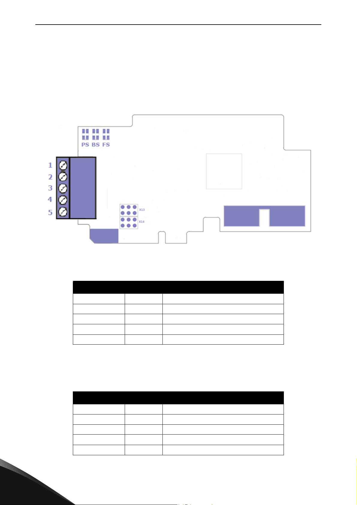
Figure 1. OPTE2 (screw plug) option board layout
Table 4. OPTE2 (screw plug) connector pinout
Signal Pin Description
Shield 1 Cable Shield
VP 2 Supply voltage - plus (5V)
RxD / TxD-P 3 Receive/Transmit data - plus(B)
RxD / TxD-N 4 Receive/Transmit data - minus(A)
DGND 5 Data ground (reference potential for VP)
NOTE! When replacing the OPTC2 option board with the OPTE2 option board, note that Receive/
Transmit data - plus (B) and Receive/Transmit data - minus (A) pins have switched places. In OPTC2,
the pin 1 is not connected to the cable shield.
Table 5. OPTC2 (screw plug) connector pinout
Signal Pin Description
NC 1 No connection
VP 2 Supply voltage - plus (5V)
RxD / TxD-N 3 Receive/Transmit data - minus (A)
RxD / TxD-P 4 Receive/Transmit data - plus (B)
4
DGND 5 Data ground (reference potential for VP)
Local contacts: https://www.danfoss.com/en/contact-us/contacts-list/
Page 11
Layout and connections vacon • 11
12345
9876
5
9
8 7 6
4 3 2 1
11727_00
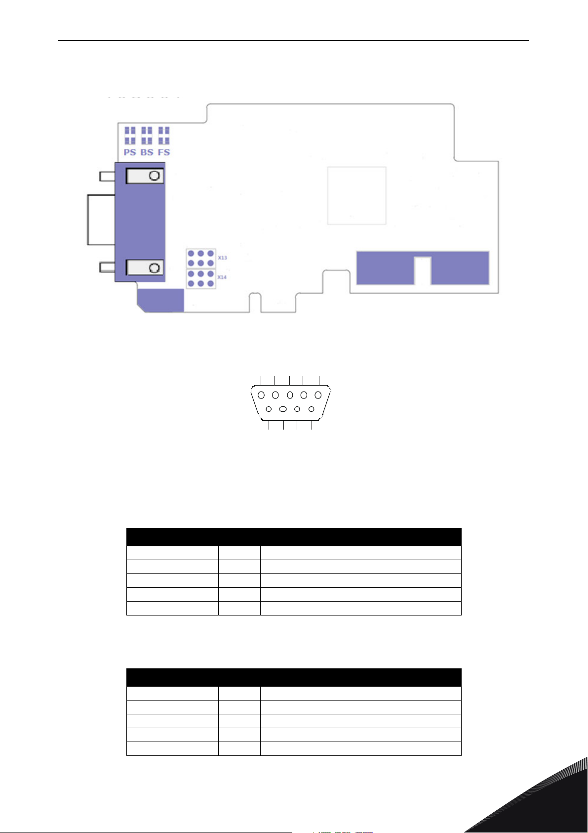
4.2 OPTE8 (Sub-D9) option board layout
Figure 2. OPTE8 (Sub-D9) option board layout
Figure 3. 9-pin female sub-D connector pinout
Table 6. OPTE8 (9-pin female sub-D) connector pinout
Signal Pin Description
Shield 1 Cable Shield
VP 6 Supply voltage - plus (5V)
RxD / TxD-P 3 Receive/Transmit data - plus (B)
RxD / TxD-N 8 Receive/Transmit data - minus (A)
DGND 5 Data ground (reference potential for VP)
NOTE! When replacing the OPTC8 option board with the OPTE8 option board, note that Receive/
Transmit data - plus (B) and Receive/Transmit data - minus (A) pins have switched places.
Table 7. OPTC8 (9-pin female sub-D) connector pinout
Signal Pin Description
Shield 1 Cable Shield
VP 6 Supply voltage - plus (5V)
RxD / TxD-N 3 Receive/Transmit data - minus (A)
RxD / TxD-P 8 Receive/Transmit data - plus (B)
DGND 5 Data ground (reference potential for VP)
Local contacts: https://www.danfoss.com/en/contact-us/contacts-list/
4
Page 12

vacon • 12 Layout and connections
4.3 LED indications
There are three LEDs on OPTE2/E8 option board to indicate board and communication status. This
table describes their indications.
Table 8. LED indications
LEDs Indication
• Green ON when protocol is communicating
PS
BS
FS
Figure below lists possible LED indication combinations.
• Yellow blinking (1s ON / 1s OFF) when protocol is ready for external communication
• OFF when protocol is not ready for communications
• Green blinking (fast) when firmware is corrupted or missing
• Green ON when board is operational.
• Red blinking (1s ON / 1s OFF) when protocol is in fault state
• Green ON when protocol is communicating.
• OFF when protocol is not communicating.
Table 9. LED combinations
LED combinations
Description
PS BS FS
Dim Dim Dim No power. All LEDs are OFF
Green Dim Dim Option board firmware is corrupted or missing. PS is blinking fast
Dim
Yello w Green Dim Protocol is ready for communications. PS is blinking (1s ON / 1s OFF)
Green Green Green
Yello w Red Dim
Green Dim Option board is operational
Protocol is communicating. The option board is receiving requests
from the PLC master and sending responses to the requests.
Protocol communication fault. BS is blinking to indicate a fault. PS is
blinking to indicate that protocol is ready for communications.
4.4 Jumpers
Setting of termination resistance and cable shield grounding options is described in Chapter 5.
4
Local contacts: https://www.danfoss.com/en/contact-us/contacts-list/
Page 13
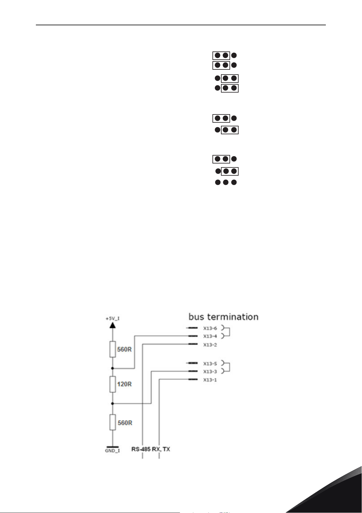
Layout and connections vacon • 13
Bus termination ON
GND connected to cable shield
Jumper X13, termination resistor
Cable shield is connected to PE through RC
Cable shield is connected directly to PE
Cable shield is not connected
Bus termination OFF
GND not connected to cable shield
Jumper X14, upper row
Jumper X14, lower row
3022B_uk
Factory default
setting
Factory default
setting
Factory default
setting
Figure 4. Position definition of jumpers
4.5 Bus terminal and bias resistors
If VACON® AC drive is the last device of RS-485 line, the bus termination must be set. Use jumper
X13 (ON position) or external termination resistors.
Bus biasing is required to ensure faultless communication between devices at RS-485 bus. Bus
biasing makes sure that the bus state is at proper potential when no device is transmitting. Without
biasing, faulty messages can be detected when the bus is in idle state. RS-485 bus state should be
neither +0.200...+7 V or -0.200...-7 V. Illegal bus state is <200 mV...-200 mV.
The resistance of internal termination and biasing are 120 Ω and 560 Ω.
Local contacts: https://www.danfoss.com/en/contact-us/contacts-list/
Figure 5. Bus termination
4
Page 14
vacon • 14 Layout and connections
If necessary, external termination and biasing can be added depending on number of nodes and
total length of cable.
Table 10. Bias resistance and termination resistance
Number of nodes Bias resistance Termination resistance
2-5 1.8 kΩ
5-10 2.7 kΩ
11-20 12 kΩ
21-30 18 kΩ
31-40 27 kΩ
120 Ω
Figure 6.
4
Local contacts: https://www.danfoss.com/en/contact-us/contacts-list/
Page 15
Cabling instructions vacon • 15
5. CABLING INSTRUCTIONS
5.1 Selecting cable
In EIA-485 systems, use only shielded cables with twisted-pair signal wires. With EIA-485 protocols,
use for example:
• Lapp Kabel UNITRONICR BUS LD FD P A, part number 2170813 or 2170814
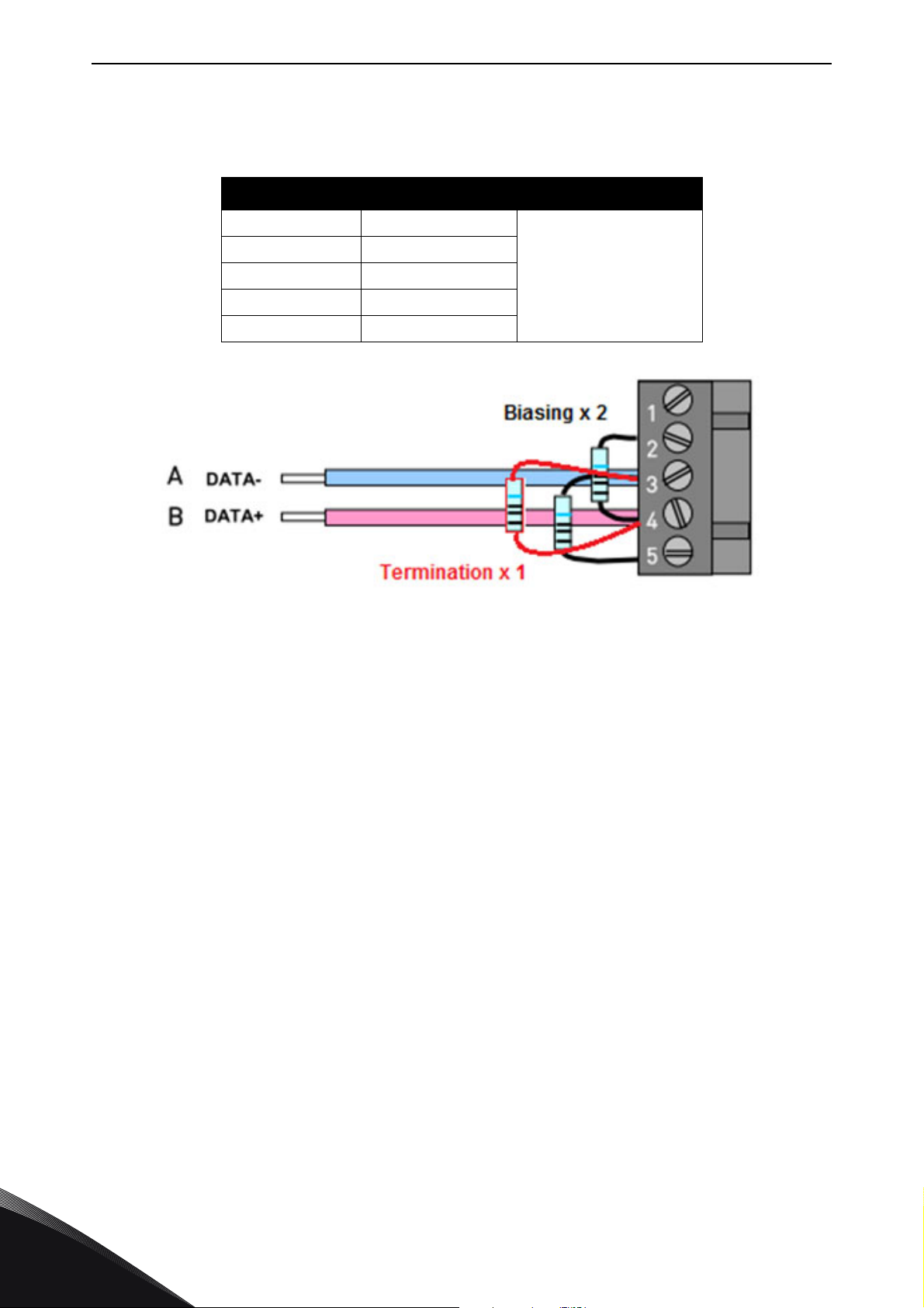
5.2 Setting the termination resistance
Install termination resistors at or near both ends of the EIA-485 segment. The typically termination
resistor for EIA-485 is 120 Ω.
A. The termination is activated D. The bus termination
B. The termination is deactivated E. The fieldbus cable
C. The termination is activated with a jumper
Figure 7. Setting the termination resistance
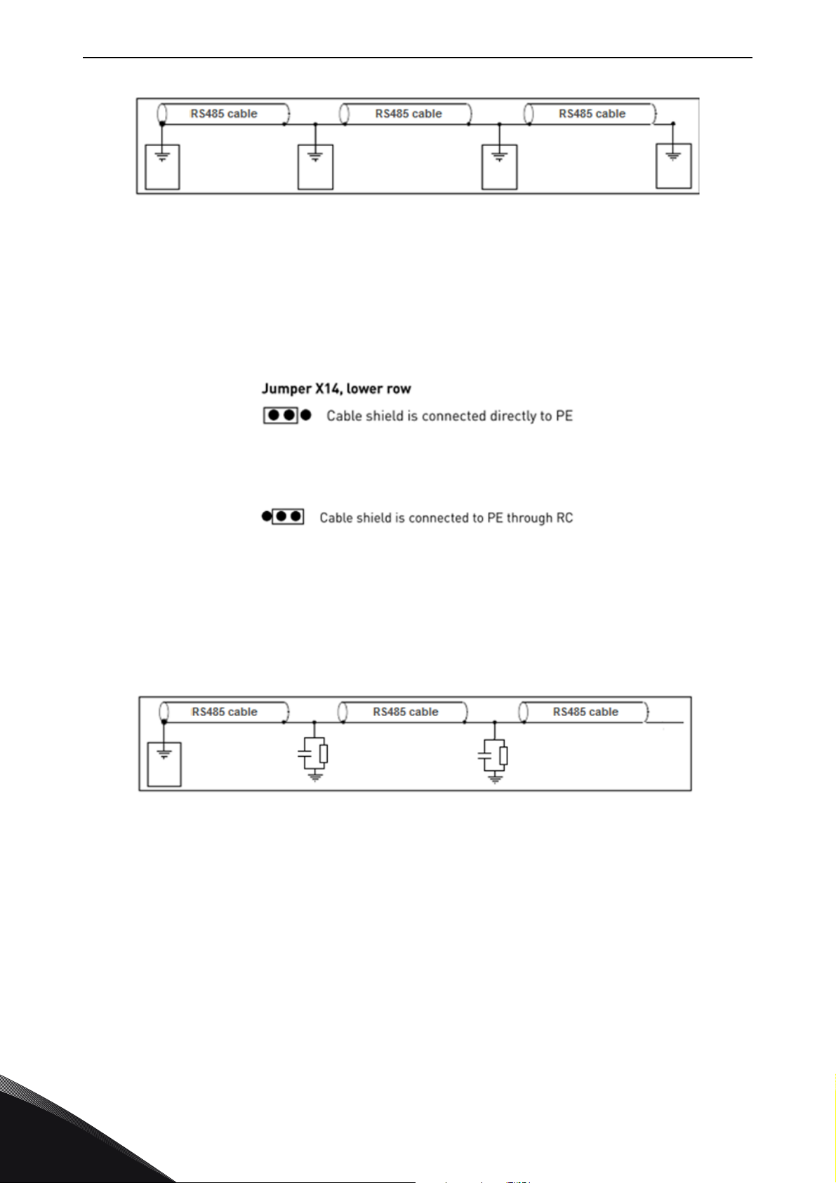
5.3 Shield grounding options
The equipotential bonding system in an installation refers to metalwork that is used to bring earth
potential everywhere in the installation to a common level, the system earth. The purpose is that the
earth potential for all devices and equipment would be same, avoiding undesirable current flow
through paths not normally designed to carry current, and to allow efficient shielding of cables.
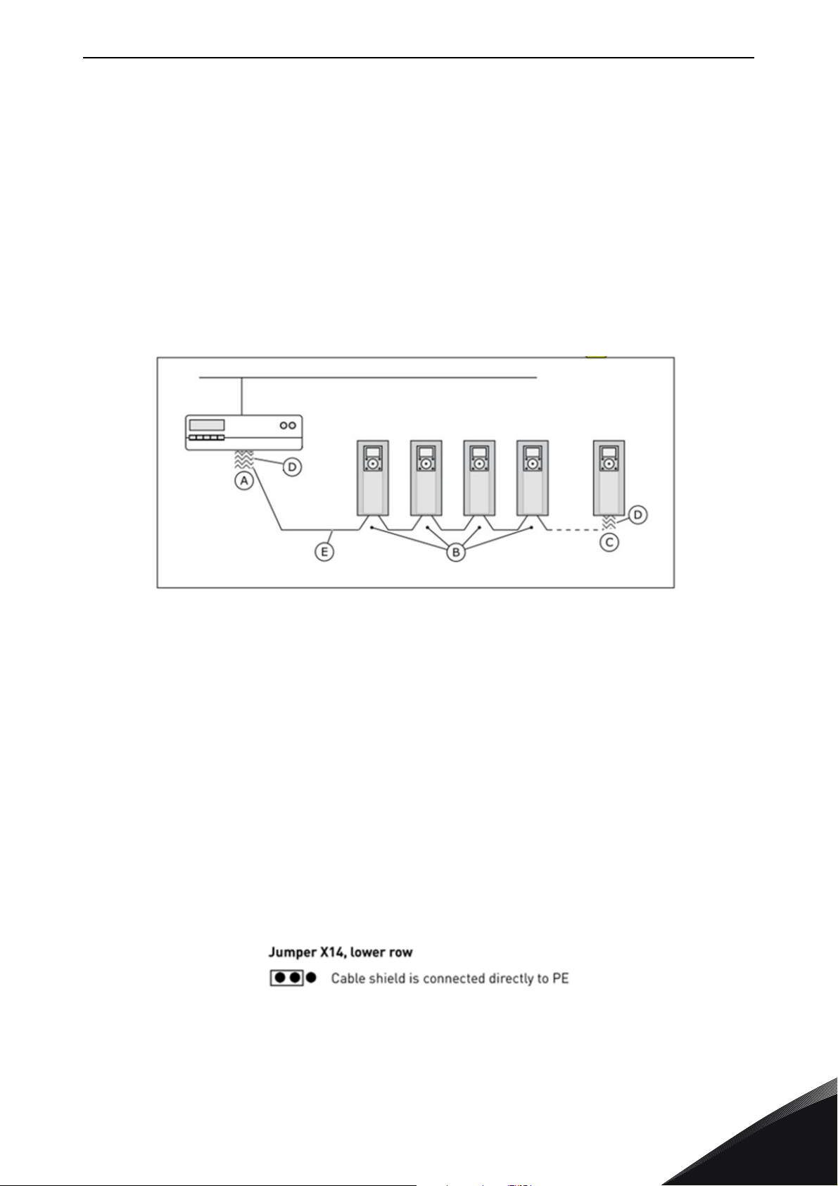
5.3.1 Shield grounding when equipotential bonding is good
When the equipotential bonding is good, the fieldbus cable shield can be grounded at each AC drive.
The grounding can be done by connecting the shield to the drive frame directly, or it can be done
through the fieldbus connector and the grounding tab in the option board.
Figure 8. Jumper X14 setting (all points in system)
If the fieldbus cable is subjected to tensile load, it is recommended to do this grounding via the
fieldbus board connector and grounding tab. The strain relief of the cable is then done without
exposing the cable shield, which reduces the risk of mechanical wear on the cable.
Local contacts: https://www.danfoss.com/en/contact-us/contacts-list/
5
Page 16
vacon • 16 Cabling instructions
Figure 9. Grounding by clambing the cable to the AC drive frame
5.3.2 Shield grounding when equipotential bonding is poor
In a situation where the equipotential bonding is poor, the fieldbus cable should be grounded directly
only at one point in the system. This can be a VACON
the system. The fieldbus cable should not be directly grounded elsewhere in the system, because
difference in electrical potential can cause equalization currents to appear in the shield, causing
unnecessary disturbances.
Figure 10. Jumper X14 setting (cable grounding to drive)
Figure 11. Jumper X14 setting (cable shield to RC filter)
In VACON
filter, which helps filter out disturbances in the shield without directly connecting it to the earth. In
this case, the shield is connected to the option board connector and through an RC filter to the
grounding tab in the option board. The strain relief is done without exposing the cable shield.
®
AC drives, the fieldbus cable can in these cases be connected to ground through an RC
®
AC drive but can also be some other point in
5
Figure 12. Grounding with RC filter
Local contacts: https://www.danfoss.com/en/contact-us/contacts-list/
Page 17

Installation vacon • 17
6. INSTALLATION
Following table shows which drives support OPTE2/E8 option board.
Table 11. OPTE2/E8 option board support
VACON
VACON
VACON
VACON
VACON
VACON
VACON
Drive Slot
®
20
®
20 X/CP
®
100 INDUSTRIAL /100 X
®
100 FLOW
®
100 HVAC
®
NXP
®
NXS
Since drive software
version
E FW0107V013 FW0204V002
E FW00117V012 FW0204V002
D, E FW0072V026 FW0204V002
D, E FW0159V017 FW0204V002
D, E FW0065V035 FW0204V002
D, E NXP00002V197 FW0204V003
D, E NXS00002V184 FW0204V003
Since OPTE2/E8
software version
Local contacts: https://www.danfoss.com/en/contact-us/contacts-list/
6
Page 18
vacon • 18 Installation
13006.emf
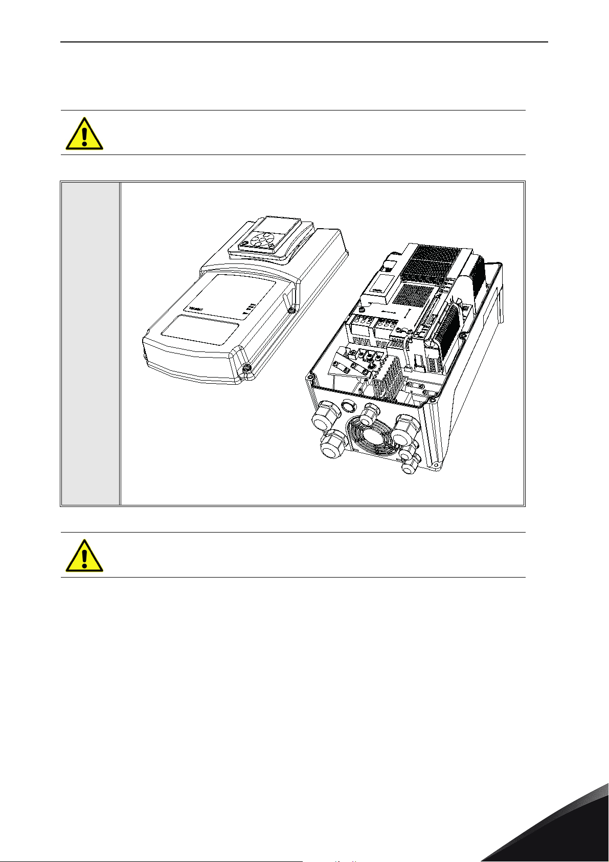
6.1 Installation in VACON® 20
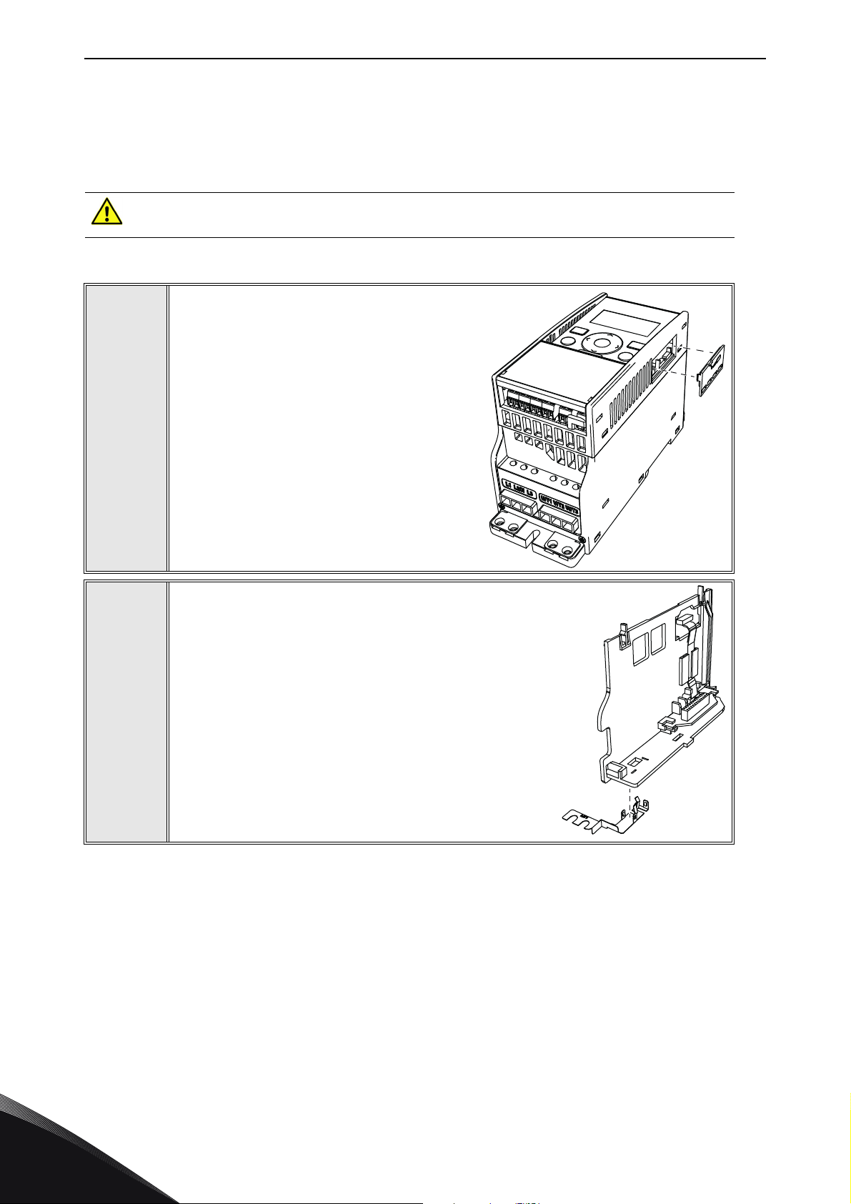
6.1.1 Enclosures MI1, MI2, MI3
Make sure power is disconnected before installing the option board mounting kit.
Remove the cable connector lid from AC
drive.
1
2
11555A_00
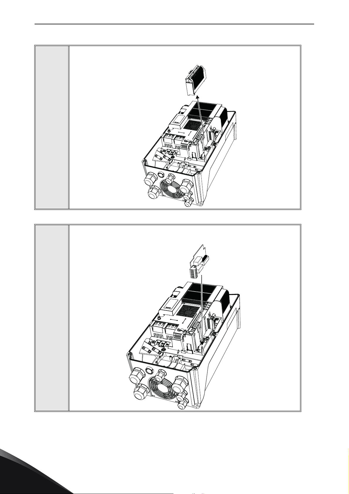
Select a correct grounding plate and attach it to the
option board mounting frame. The grounding plate is
marked with the supported enclosure size.
11649_00
Local contacts: https://www.danfoss.com/en/contact-us/contacts-list/
6
Page 19
Installation vacon • 19
11556A_
11558A_00
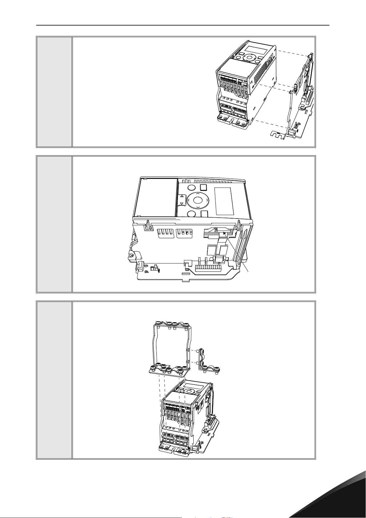
Attach an option board mounting frame to the
AC drive.
3
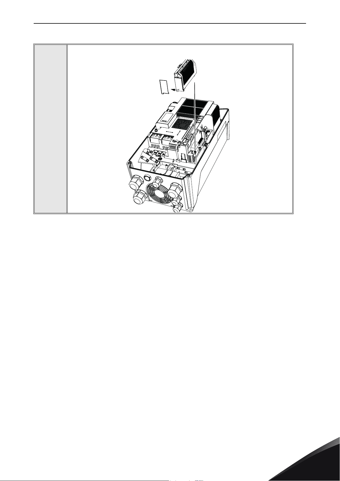
Connect the flat cable from the option board mounting frame to the AC drive.
4
5
11557A_00
If a cable strain relief is required, attach the parts as shown in the figure.
Local contacts: https://www.danfoss.com/en/contact-us/contacts-list/
6
Page 20
vacon • 20 Installation
11559A_00
11650_00
11560A_00
Install the option board to the option board
holder. Make sure that the option board is
securely fastened.
6
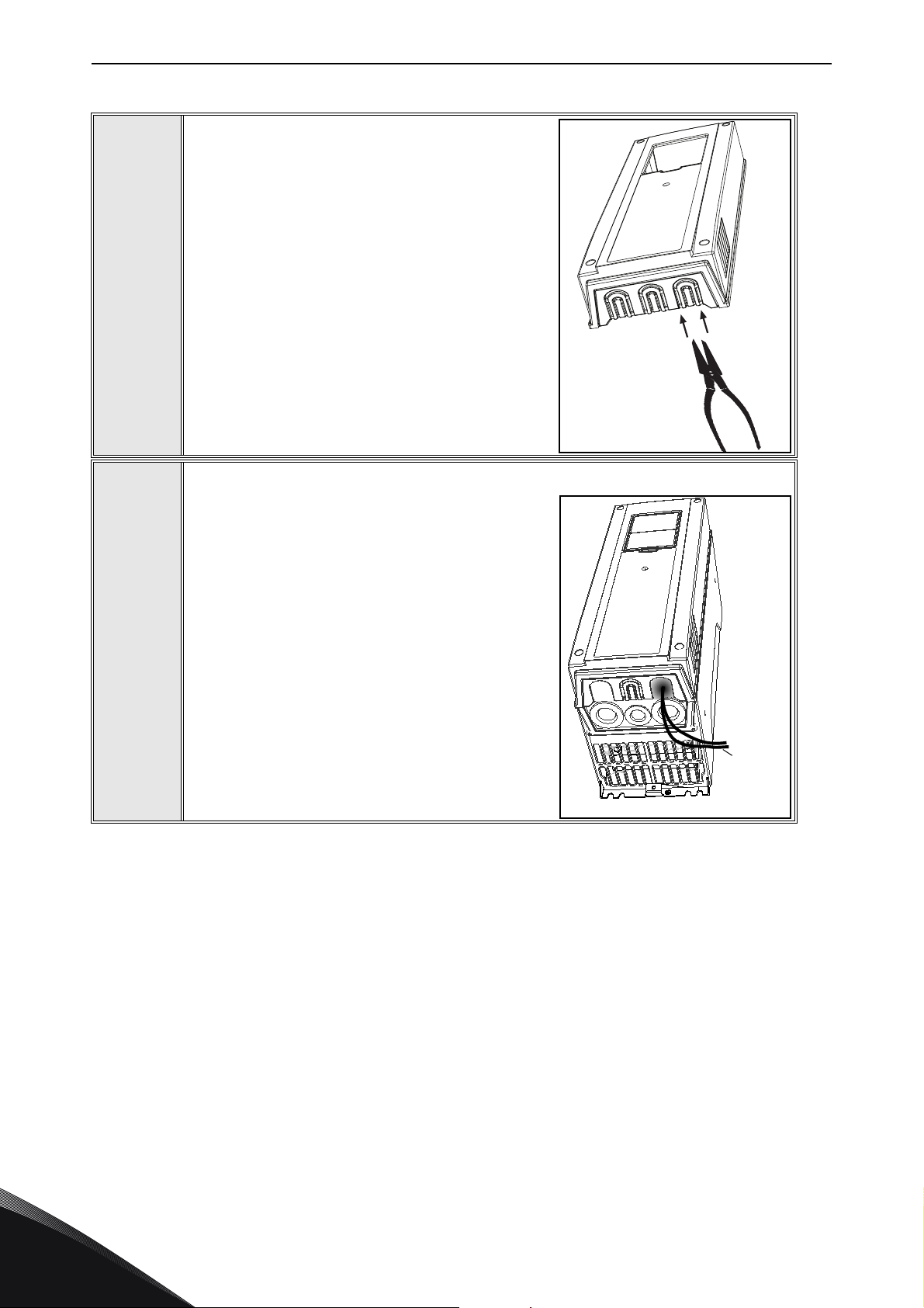
Cut free a sufficiently wide opening for the
option board connector.
7
8
Attach the option board cover to the AC drive. Attach the strain relief cable clamp
with screws if needed.
6
Local contacts: https://www.danfoss.com/en/contact-us/contacts-list/
Page 21
Installation vacon • 21
13006.emf
11562_00
11563_00
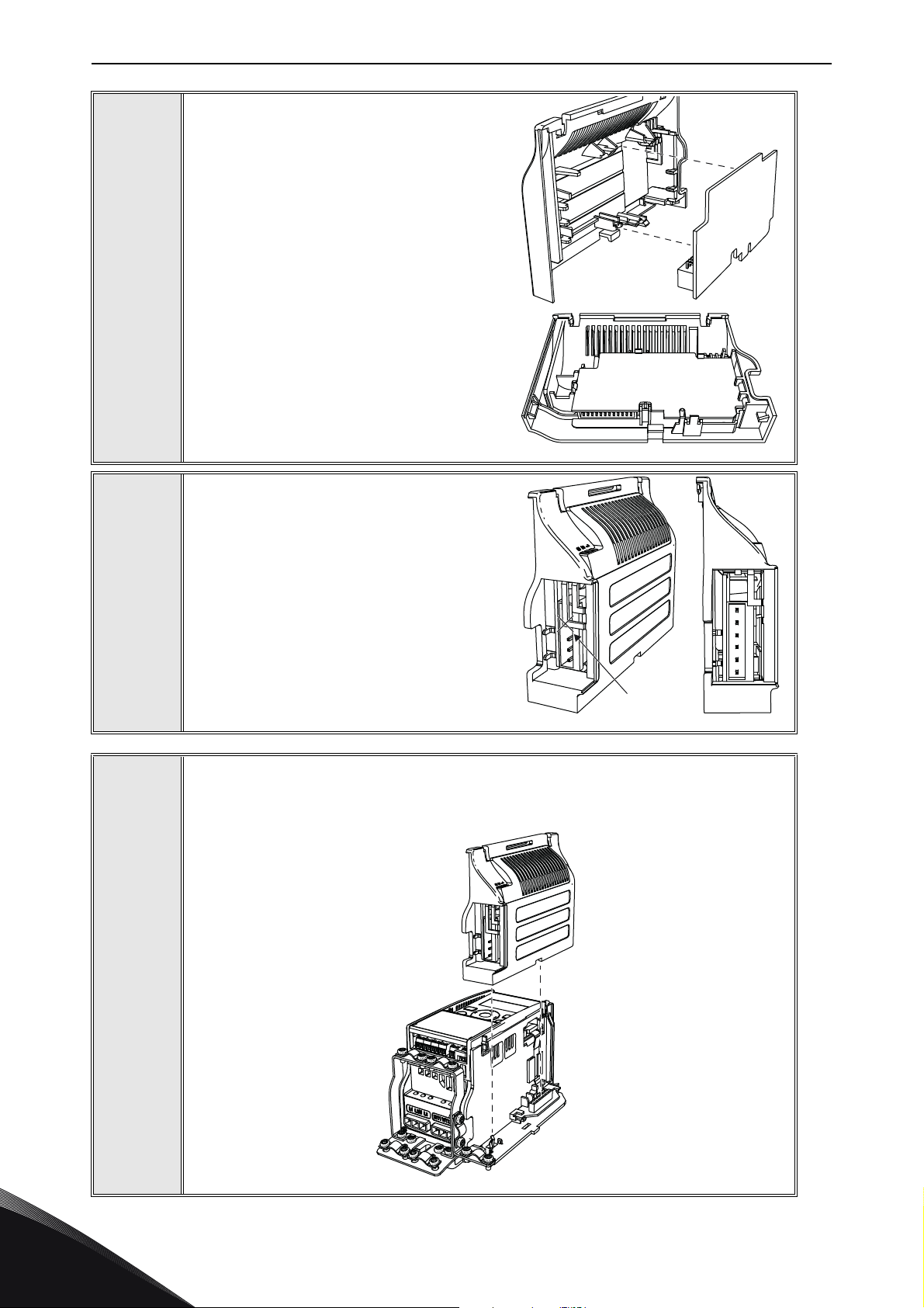
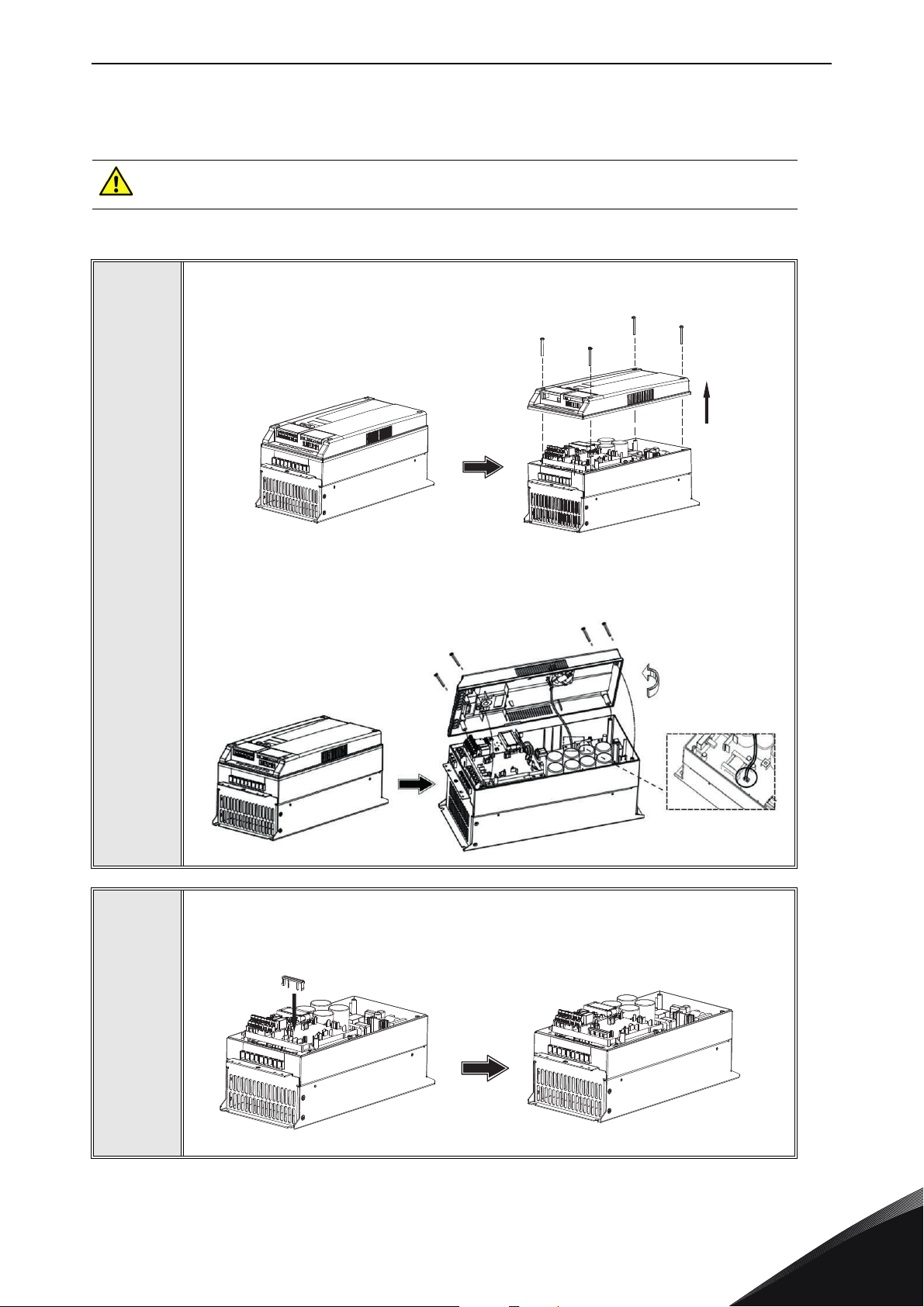
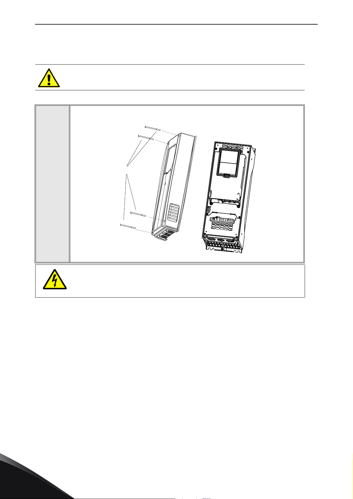
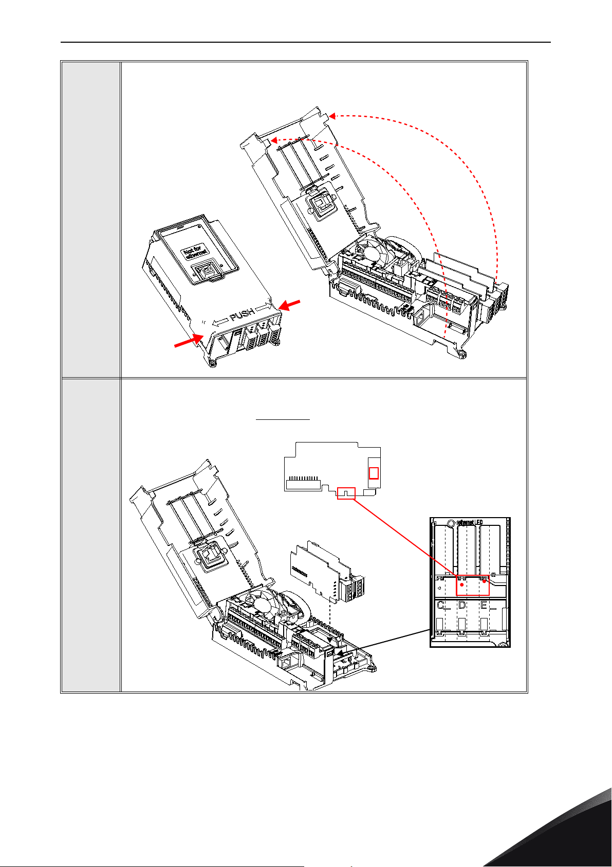
6.1.2 Enclosures MI4, MI5
Make sure power is disconnected before opening the cover of the AC drive.
1a: For MI4: Open the cover.
1
11561_00
1b: For MI5: Open the cover and release the fan connector.
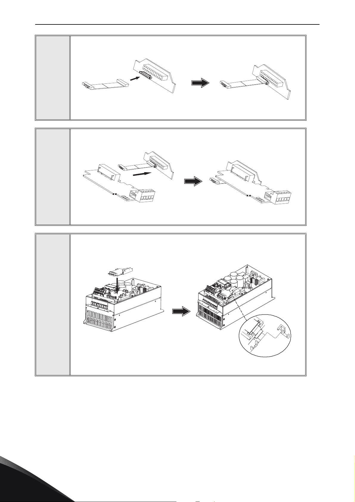
OPTE2: Attach the option board support.
OPTE8: Option board support is not used.
2
Local contacts: https://www.danfoss.com/en/contact-us/contacts-list/
6
Page 22
vacon • 22 Installation
11564_00
11565_00
Connect the flex cable to option board connector PCB.
3
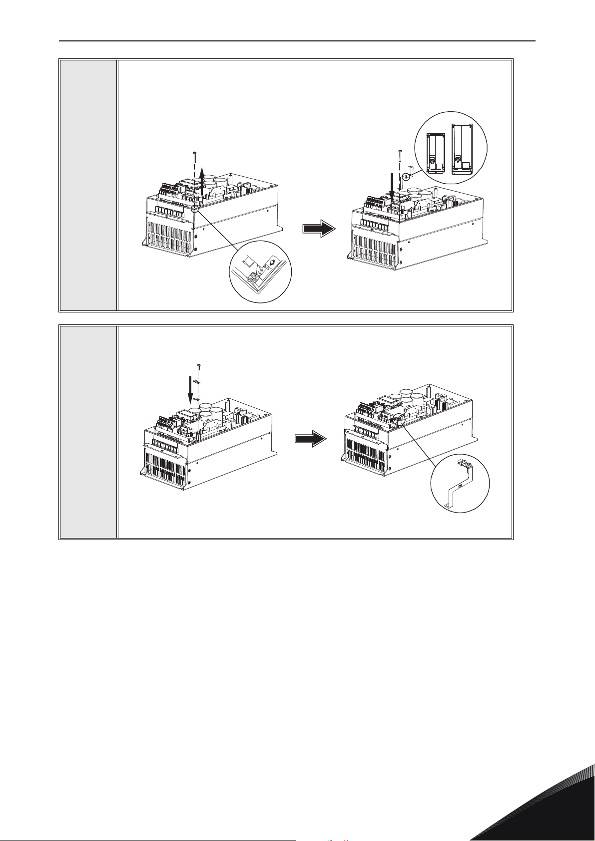
Connect the option board to connector PCB.
4
5
Attach the option board with connector PCB to the AC drive and connect the flex
cable.
11566_00
6
Local contacts: https://www.danfoss.com/en/contact-us/contacts-list/
Page 23
Installation vacon • 23
MI 04
MI 05
11567_00
11568_00
Attach a suitable grounding plate to VACON® 20. The grounding plate is marked
with supported enclosure size.
6
7
Assemble a clamp on top of the grounding plate on both sides of the option board.
Local contacts: https://www.danfoss.com/en/contact-us/contacts-list/
6
Page 24
vacon • 24 Installation
11569_00
11570_00
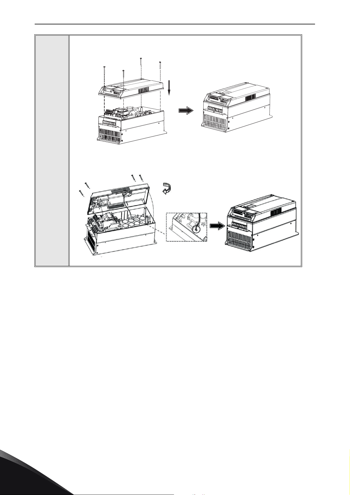
8a: For MI4: Close the cover.
8
8b: For MI5: Remount the fan connector and close the cover.
6
Local contacts: https://www.danfoss.com/en/contact-us/contacts-list/
Page 25
Installation vacon • 25
13006.emf
13006.emf
6.2 Installation in VACON® 20 X and 20 CP
Do not add or replace option boards or fieldbus boards on an AC
drive with the power switched on. This may damage the boards.
Open the cover of the drive.
1
11643_00
MU3 example
The relay outputs and other I/O-terminals may have a dangerous control voltage
present even when the drive is disconnected from mains.
Local contacts: https://www.danfoss.com/en/contact-us/contacts-list/
6
Page 26
vacon • 26 Installation
7089_00
Remove the option slot cover.
2
3
Install the option board into the slot as shown in the figure.
6
7090_00
Local contacts: https://www.danfoss.com/en/contact-us/contacts-list/
Page 27
Installation vacon • 27
7091_007091_00
Mount the option slot cover. Remove the plastic opening for the option board
terminals.
4
Local contacts: https://www.danfoss.com/en/contact-us/contacts-list/
6
Page 28
vacon • 28 Installation
13006.emf
M4x55
9174.emf
DANGER
6.3 Installation in VACON® 100 family
Do not add or replace option boards or fieldbus boards on an AC
drive with the power switched on. This may damage the boards.
Open the cover of the AC drive.
1
The relay outputs and other I/O-terminals may have a dangerous control voltage
®
present even when VACON
100 family AC drive is disconnected from mains.
6
Local contacts: https://www.danfoss.com/en/contact-us/contacts-list/
Page 29
Installation vacon • 29
3023.emf
DE
3024.emf
Open the inner cover to reveal the option board slots (C,D,E). See the figure
below.
2
3
Install the fieldbus board into slot D or E. See the figure below.
®
NOTE! Incompatible boards cannot be installed on VACON
Compatible boards have a slot coding
that enable the placing of the board.
100 family AC drive.
Local contacts: https://www.danfoss.com/en/contact-us/contacts-list/
6
Page 30
vacon • 30 Installation
f
9202.emf
Fieldbus
cables
Unless already done for the other control cables,
cut free the opening on the AC drive cover for the
fieldbus cable (protection class IP21).
NOTE! Cut the opening on the same side you
have installed the board in
4
5
9201.em
Remount the AC drive cover and run the cable as shown in the figure.
NOTE! When planning the cable runs, remember
to keep the distance between the fieldbus cable
and the motor cable at a minimum of 30 cm. It is
recommended to route the option board cables
away from the power cables as shown in the
figure.
6
Local contacts: https://www.danfoss.com/en/contact-us/contacts-list/
Page 31
Installation vacon • 31
6.4 Installation in VACON® 100 X (enclosures MM4-MM6)
Open the cover of the AC drive.
1
11638_00
Local contacts: https://www.danfoss.com/en/contact-us/contacts-list/
6
Page 32

vacon • 32 Installation
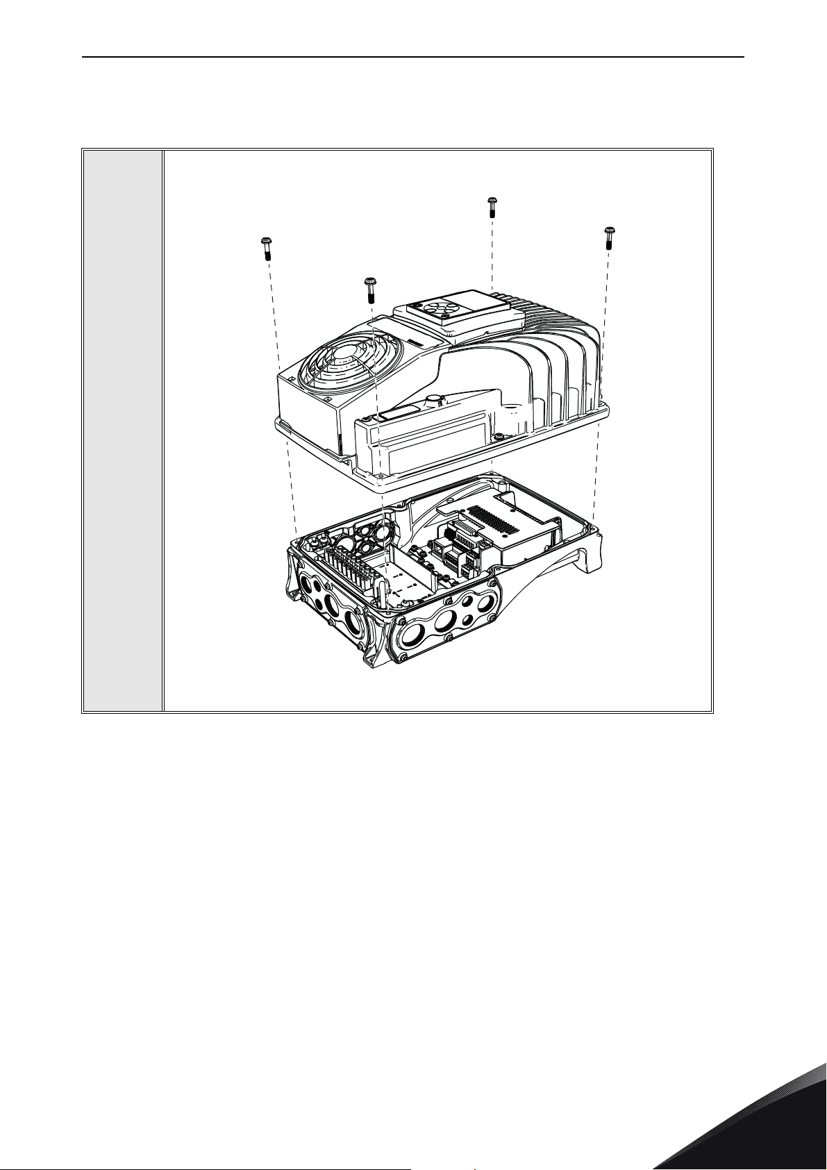
11639_00
To get access to the option board slots, remove the screws and open the cover of
the control unit.
2
6
Local contacts: https://www.danfoss.com/en/contact-us/contacts-list/
Page 33

Installation vacon • 33
DE
11640_00
11641_00
Install the option board into the correct slot, D or E.
3
4
Close the option board cover.
5
Remove the cable entry plate. If you
installed the option board in the slot
D, use the cable entry plate on the
right side. If you installed the option
board in the slot E, use the cable
entry plate on the left side.
NOTE! The cable entry plate at the
bottom of the drive is used only for
mains and motor cables.
Local contacts: https://www.danfoss.com/en/contact-us/contacts-list/
6
Page 34

vacon • 34 Installation
6
7
Open the necessary holes in the cable entry plate. Do not open the other holes.
See the VACON
Attach a cable gland on the hole in the
cable entry plate. Pull the fieldbus cable
through the hole.
NOTE! The fieldbus cable must go through
the correct cable entry plate to avoid going
near the motor cable.
®
100 X Installation Manual for the dimensions of the holes.
11642_00
8
9
Put the cable entry plate back.
Close the cover of the AC drive.
6
Local contacts: https://www.danfoss.com/en/contact-us/contacts-list/
Page 35

Installation vacon • 35
13006.emf
6.5 Installation in VACON® NX
Make sure that the AC drive is switched off before an option or fieldbus board is
changed or added!
VACON® NX AC drive.
1
2
3
Remove the cable cover.
Open the cover of the control unit.
Local contacts: https://www.danfoss.com/en/contact-us/contacts-list/
6
Page 36

vacon • 36 Installation
Install the OPTE2/E8 RS485 option board in slot D or E on the control board of the
AC drive. Make sure that the grounding plate fits tightly in the clamp.
4
Make a sufficiently wide opening for your cable by cutting the grid as wide as
necessary.
5
6
Close the cover of the control unit and the cable cover.
6
Local contacts: https://www.danfoss.com/en/contact-us/contacts-list/
Page 37

Installation vacon • 37
6.6 VACON® PC tools
With VACON® PC tools it is possible to do following operations for OPTE2/E8 RS485:
• Update firmware into OPTE2/E8 RS485 option board
• Set parameters for OPTE2/E8 RS485
• Read monitor values of OPTE2/E8 RS485
6.6.1 PC tool support
This table describes what PC tools are supported in each AC drive type. The connection type "serial"
means a direct serial connection to the AC drive. The connection type "Ethernet" means that
Ethernet connection is supported by using for example via VACON
interface or via OPTE9 Dual Port Ethernet option board.
Table 12. The supported PC tools with different AC drives
VACON® 100 family VACON® NXS/NXP VACON® 20 family
Too l
Serial Ethernet Serial Ethernet Serial Ethernet
®
100 family built-in Ethernet
VACON® Loader
VACON
®
Live
xxx
xx x
NCIPConfig Not used with OPTE2/E8 RS485
NCDrive x x
NCLoad Not used with OPTE2/E8 RS485
6.6.2 OPTE2/E8 option board firmware update with
You can update OPTE2/E8 RS485 firmware with VACON
•PC with VACON
®
•VACON
AC drive in which OPTE2/E8 RS485 option board is installed
®
Loader installed
®
Loader PC tool. You need to have:
VACON
®
Loader
• Serial cable:
®
-VACON
NXP/NXS is connected to PC with RS232 serial cable which is connected from PC to
NXP/NXS control unit's 9-pin DSUB connector (female). If PC does not contain RS232 serial
port, then USB - RS232 converter device is needed between PC and NXP/NXS control.
®
-VACON
The VACON
100 family and VACON® 20 are connected to PC with VACON® Serial Cable.
®
Loader can be downloaded from https://www.danfoss.com/en/service-and-support/
Downloads Software Select "Drives" as Business unit. It is bundled with the VACON
software package. After starting the installation program, follow the on-screen instructions.
®
Live
The OPTE2/E8 RS485 firmware can be downloaded from https://www.danfoss.com/en/service-and-
support/ Downloads Software Select "Drives" as Business unit Fieldbus firmware.
To update the option board firmware, follow the steps below.
NOTE! With VACON
the following baud rates are supported: 9600, 19200, 38400 or 57600. With VACON
®
VACON
Local contacts: https://www.danfoss.com/en/contact-us/contacts-list/
NX family AC drives VACON® Loader selects a correct baud rate automatically.
®
20, the baud rate 9600 must be used. With VACON® 20 X and VACON® 20 CP,
®
100 family and
6
Page 38

vacon • 38 Installation
Step 1: Connect your PC to the controller by using the serial cable.
Then select the firmware file which you want to load to the option board and double click it. This will
start the VACON
In this case, select the firmware file using the "Browse" button.
®
Loader software. You can also start the program from the Windows Start menu.
Figure 13. VACON
Step 2: Press 'next' and wait for the loader to find the network drives. Then select a drive from the
list and press 'Connect to Selected'.
Figure 14. VACON
®
Loader: File selection
®
Loader: Connecting to drive
6
Local contacts: https://www.danfoss.com/en/contact-us/contacts-list/
Page 39
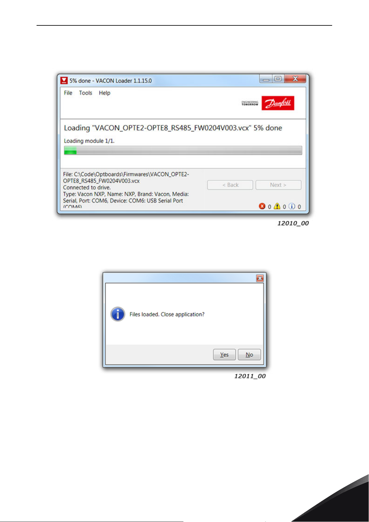
Installation vacon • 39
Step 3: Select the modules to be updated, press 'next' and wait until the operation is finished. See
Figures below.
Figure 15. VACON
Figure 16. VACON
®
Loader: Firmware loading
®
Loader: Loading is finished
Local contacts: https://www.danfoss.com/en/contact-us/contacts-list/
6
Page 40

vacon • 40 Installation
6.6.3 PC tools for VACON® NXP/NXS: NCDrive
You can configure the VACON
NCDrive PC tool. You need to have:
• PC with NCDrive installed
®
•VACON
• In case of Serial connection:
- If PC contains RS232 serial port, then connect the serial cable from PC to NXP/NXS control
unit's 9-pin DSUB connector (female).
- If PC does not contain RS232 serial port, then USB - RS232 converter device is needed
between PC and NXP/NXS control.
• In case of Ethernet connection:
- Ethernet cable which is connected to option board's Ethernet interface.
-VACON
OPTE9 Dual Port Ethernet option board.
The NCDrive can be downloaded from https://www.danfoss.com/en/service-and-support/
Downloads Software Select "Drives" as Business unit. After starting the installation program,
follow the on-screen instructions.
Once the program is installed successfully, you can launch it by selecting it in the Windows Start
menu. Select Help Contents if you want more information about the software features.
6.6.3.1
NXP/NXS drive
®
NXP/NXS requires option board supporting Ethernet communication. For example,
NCDrive Serial communication settings
®
NXP/NXS AC drive and OPTE2/E8 RS485 parameters with the
Connect your PC to the controller by using the USB/RS485 cable.
Select Tools Options… Communication tab. Then define settings for your USB - RS232 adapter
and press OK.
6
Figure 17. NCDrive: Serial communication settings
Local contacts: https://www.danfoss.com/en/contact-us/contacts-list/
Page 41
Installation vacon • 41
6.6.3.2 NCDrive Ethernet communication settings
For NCDrive Ethernet connection you need to have:
• Working Ethernet connection between PC and AC drive
• NCDrive is parametrized to use Ethernet connection
See instructions from Ethernet option board manual. Option board manuals can be downloaded
from https://www.danfoss.com/en/service-and-support/ Documentation Select "Drives" as
Business unit Select "VACON
®
Option Boards" as Product Series.
6.6.3.3
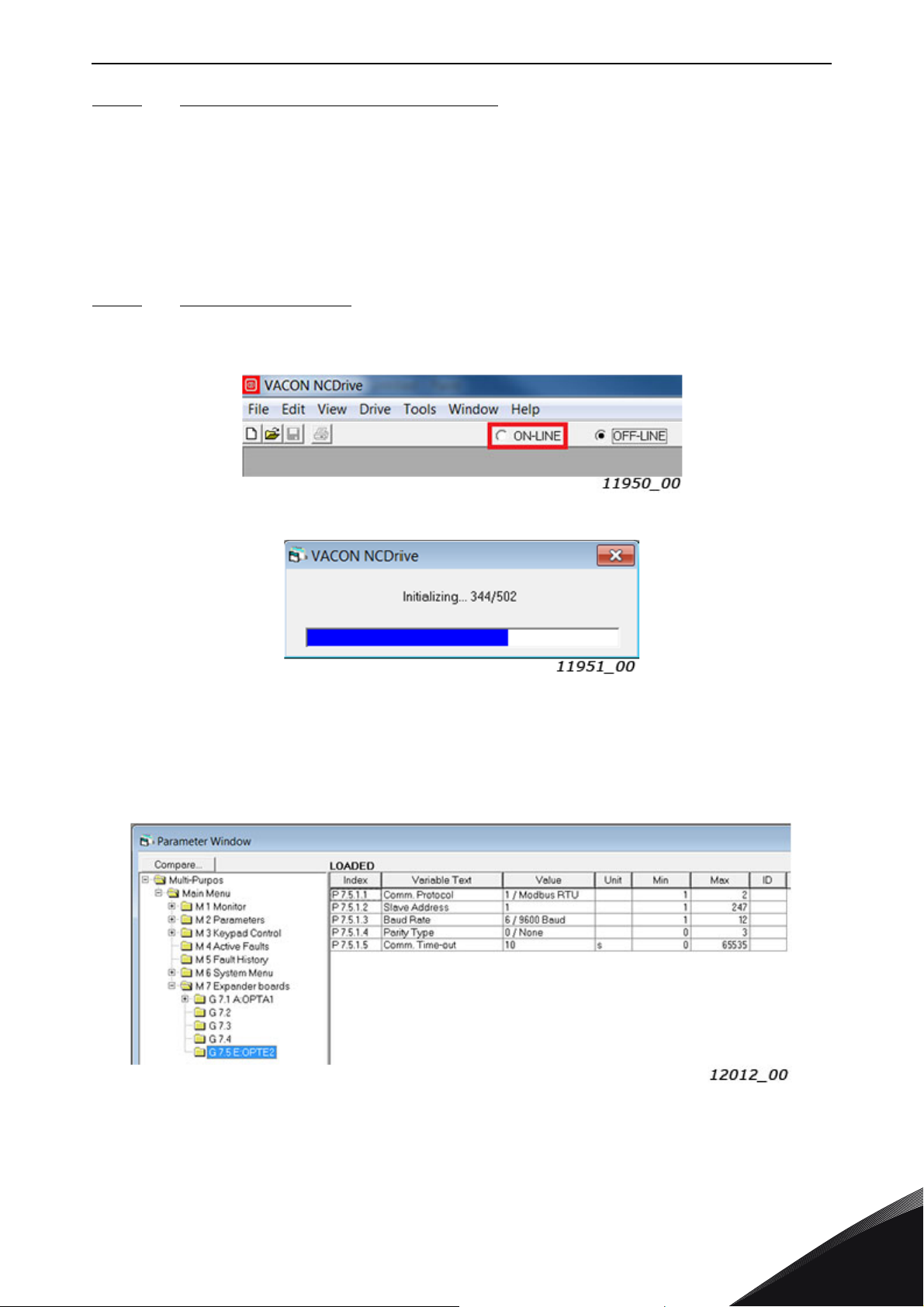
Press the "ON-LINE" button. The NCDrive will connect to the drive and start loading parameter
information. See Figures below.
Connecting to NCDrive
Figure 18. NCDrive: Going online
Figure 19. NCDrive: Loading information from the drive
To change the option board settings, navigate to the "M 7 Expander boards" menu and select the slot
to which OPTE2/E8 RS485 is connected. It is possible to change parameters defined in chapter 7.1.2
Option board parameter menu.
Figure 20. NC Drive: Parameter menu
Local contacts: https://www.danfoss.com/en/contact-us/contacts-list/
6
Page 42

vacon • 42 Installation
6.6.4 PC tools for VACON® 100 family and VACON® 20: VACON® Live
You can configure the VACON
RS485 parameters with VACON
VACON
®
Live. You need to have:
®
100 family AC drives, VACON® 20 family AC drives and OPTE2/E8
®
Live PC tool. Also monitor values of these devices can be read with
•PC with VACON® Live installed
®
•VACON
100 family or VACON® 20 family AC drive
• In case of Serial connection:
-VACON
®
Serial Cable (USB - Serial cable) which is connected from PC to AC drive control
unit.
®
-In case of VACON
not needed in case of VACON
20 also MCA (Micro Communications Adapter) is required. This adapter is
®
20 X / CP.
• In case of Ethernet connection:
- Ethernet cable which is connected to AC drive's Ethernet interface.
®
-In case of VACON
100 family it is possible to use built-in Ethernet connection or Ethernet
option board (for example OPTE9 Dual Port Ethernet).
NOTE! VACON
®
20, VACON® 20 X and VACON® 20 Cold Plate do not support VACON® Live
connection over Ethernet.
®
VACON
Live can be downloaded from https://www.danfoss.com/en/service-and-support/
Downloads Software Select "Drives" as Business unit. After starting the installation program,
follow the on-screen instructions.
Once the program is installed successfully, you can launch it by selecting it in the Windows Start
menu. Select Help Contents if you want more information about the software features.
6.6.4.1
VACON® Live Serial communication settings
Step 1: Connect your PC to VACON® AC drive with VACON® Serial Cable.
®
Step 2: Start VACON
Live. When the program starts, it asks "Select startup mode". Select "Online"
startup mode. After this the program scans compatible drives.
®
Figure 21. VACON
Live: To online mode
6
Local contacts: https://www.danfoss.com/en/contact-us/contacts-list/
Page 43
Installation vacon • 43
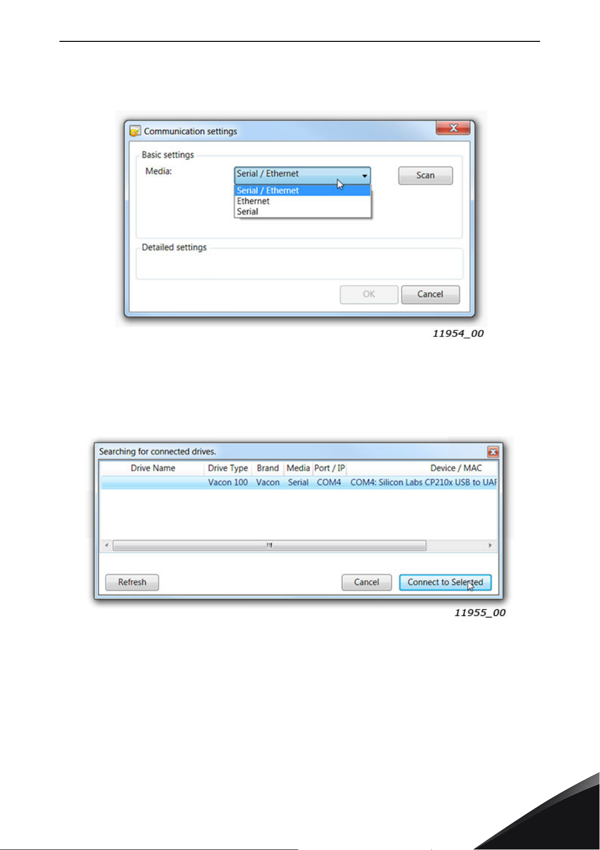
Step 2b: If VACON® Live cannot find your AC drive, then ensure that "Serial / Ethernet" or "Serial"
is selected. After that press "Scan".
Figure 22. VACON
Step 3: After successful scanning, VACON
the drive and press "Connected to Selected". After this VACON
value tree from the drive.
Figure 23. VACON
®
Live: Communication settings
®
Live shows the drive in connected drives window. Select
®
Live: Communication settings
®
Live reads parameter and monitor
Local contacts: https://www.danfoss.com/en/contact-us/contacts-list/
6
Page 44

vacon • 44 Installation
6.6.4.2 VACON® Live Ethernet communication settings
For VACON® Live Ethernet connection you need to have:
• Working Ethernet connection between PC and AC drive
•VACON
®
Live is parametrized to use Ethernet connection
See instructions from Modbus, PROFINET IO, EtherNet/IP, BACnet/IP or OPTEA-OPTE9 Ethernet
option board manuals for VACON
®
100 family. Manuals can be downloaded from https://
www.danfoss.com/en/service-and-support/ Documentation Select "Drives" as Business unit
Select "VACON
6.6.4.3
®
Option Boards" as Product Series.
OPTE2/E8 RS485 parameters in VACON® Live
OPTE2/E8 RS485 parameters and monitor values can be found from "5. I/O and Hardware" menu.
®
With VACON
Live it is possible to modify OPTE2/E8 RS485 parameters and view monitor values.
Figure 24. VACON
®
Live: OPTE2/E8 RS485 parameters
6
Local contacts: https://www.danfoss.com/en/contact-us/contacts-list/
Page 45

Commissioning vacon • 45
7. COMMISSIONING
OPTE2/E8 is commissioned with VACON® 20 keypad, VACON® 100 family panel or with VACON® NX
family panel by setting appropriate parameters in the option board menu. Also PC tools can be used
for OPTE2/E8 parametrization (see Chapter 6.6 "VACON
Keypad/Panel commissioning and location of parameters are different between these two types of
drives.
Table 13. Parameter location for commissioning
Drive Parameters location
®
PC tools").
VACON® 20
VACON
VACON
NOTE! The AC drive application must be parametrized to enable motor controlling from the fieldbus.
For application parametrization instructions, see Chapter 10 "Appendix A - Fieldbus
parametrization".
®
100 family
®
NX family
'System Menu' P 2.x
'I/O and Hardware (M7)' Slot D' or 'Slot E'
Expander boards menu (M7) Slot D' or
'Slot E'
7.1 Option board menu
The keypad/panel makes it possible for users to see which option board is connected to drive, and
to reach and edit the parameters associated with option board.
7.1.1 Option board monitor menu
Table 14. Option board monitor menu
Monitor Range Description
Fieldbus protocol
status
1 = Initializing,
3 = Operational,
4 = Faulted
Communication Status
Protocol/fieldbus
control word
Protocol/fieldbus status
word
Communication status
The number of messages with errors counter is increased when OPTE2/E8 receives a corrupted
frame from the bus. The content of the corrupted message cannot be parsed.
The number of messages without communication errors counter is increased when OPTE2/E8
receives a valid Modbus RTU or N2 frame from the bus. Also the frame that is addressed to some
other slave device increases the counter.
Local contacts: https://www.danfoss.com/en/contact-us/contacts-list/
X.Y
0.0 … 64.999
- Control word received from RS-485
-Status word in drive format
X = Number of messages with errors
Y = Number of messages without communication errors
7
Page 46

vacon • 46 Commissioning
7.1.2 Option board parameter menu
Table 15. Option board parameter menu
Parameter Range Description
Communication protocol
Slave address 1 … 247 Slave address
Baud rate
Parity
Communication timeout
Mode
1 = Modbus RTU
2 = N2
1 = 300 bps
2 = 600
3 = 1200
4 = 2400
5 = 4800
6 = 9600
7 = 19200
8 = 38400
9 = 57600
10 = 76800
11 = 115200
12 = 230400
0 = None
1 = Even
2 = Odd
3 = None Stopbits1
0 = Disable
1 … 65535 s
1 = Normal
2 = NX mode
Current active fieldbus protocol. Default
communication protocol is Modbus RTU
Baud rate. Default baud rate is 9600 bps. When
N2 protocol is used baud rate must be set to
9600.
Modbus RTU:
Parity None 2 stop bit
Parity Even 1 stop bit
Parity Odd 1 stop bit
Parity None Stopbits1 1 stop bit
N2 always uses 1 stop bit.
Protocol communication timeout
NX mode enables OPTC2/OPTC8 RS485
emulation. See Chapter "OPTC2/OPTC8 RS485
compatibility mode".
Communication timeout
The OPTE2/E8 RS485 option board reports communication timeout fault to the AC drive if the option
board cannot receive Modbus RTU or Metasys N2 request during a communication timeout time. For
more information on the fault, see Chapter 14.3 "Fieldbus timeout fault (F53)".
Only Modbus RTU or Metasys N2 requests that are pointed to the option board are taken into account
in the communication timeout calculation. Requests that are pointed to other devices do not affect
the timeout calculation.
Timeout monitoring starts after one valid request is received from the master.
The OPTE2/E8 RS485 does not create communication timeout fault to the drive when the timeout
value is set to zero. This is useful for example when Modbus RTU or N2 is used only for monitoring
the AC drive.
OPTC2/OPTC8 RS485 compatibility mode
OPTE2/OPTE8 firmware V003 and newer support the NX mode which enables emulation of the old
OPTC2/OPTC8 RS485 option board.
•In case of VACON
automatically.
- See also the related system parameter “Show to Application as” in Chapter 7.1.3 "System
Parameter menu".
®
NXP or VACON® NXS AC drive the emulation mode is enabled
7
Local contacts: https://www.danfoss.com/en/contact-us/contacts-list/
Page 47

Commissioning vacon • 47
•In case of VACON® 100 family AC drives the emulation mode can be enabled by selecting
"NX mode" with "Mode" parameter. See parameter in Chapter 7.1.2 "Option board
parameter menu".
The OPTC2/OPTC8 compatibility mode causes the following functionality changes in OPTE2/OPTE8
RS485 option board:
• N2 Binary input (BI) mapping is different. See Chapter 9.3.2 "Binary Input (BI)".
• N2 Binary output (BO) mapping is different. See Chapter 9.3.4 "Binary Output (BO)".
• Modbus RTU reading/writing of multiple VACON
writing of at least one ID succeeds. Normally OPTE2/8 returns "Illegal Data Address" (2)
Modbus error when access to one ID fails.
• Modbus RTU Holding/input register 98 reads the first active fault code.
7.1.3 System Parameter menu
Table 16. System Parameter menu
Parameter Range Description
®
application ID’s succeeds when reading/
0 = Default
Show to Application As*
*Available in VACON® NXP
Show to Application As
Some VACON
the application. In such cases, the application may refuse to go to the run state if a wrong type of
fieldbus option is installed to the drive.
With the Show to Application As parameter it is possible to modify the option board type information
that is fed to the application. For example, if an OPTC2 option board is replaced with an OPTE2 option
board, with the Show to Application As parameter it is possible to lie to the application that an OPTC2
board is installed to the drive.
With the default setting the application normally sees the OPTE2/OPTE8 option board as OPTE2 or
OPTE8 option board.
The Show to Application As parameter is available in VACON
NXP00002V198 and newer.
®
NXP applications assume that a certain fieldbus option board is used together with
17202 = OPTC2
17208 = OPTC8
Application sees the OPTE2/OPTE8 option
board as OPTC2 or OPTC8 option board if
“OPTC2” and “OPTC8” is selected.
®
NXP control firmware version
Local contacts: https://www.danfoss.com/en/contact-us/contacts-list/
7
Page 48

vacon • 48 Modbus RTU
8. MODBUS RTU
8.1 Overview
The MODBUS protocol is an industrial communications and distributed control system to integrate
PLCs, computers, terminals, and other monitoring, sensing, and control devices. MODBUS is a
Master-Slave communications protocol. The Master controls all serial activity by selectively polling
one or more slave devices. The protocol provides for one master device and up to 247 slave devices
on a common line. Each device is assigned an address to distinguish it from all other connected
devices.
The MODBUS protocol uses the master-slave technique, in which only one device (the master) can
initiate a transaction. The other devices (the slaves) respond by supplying the request data to the
master, or by taking the action requested in the query. The master can address individual slaves or
initiate a broadcast message to all slaves. Slaves return a message ('response') to queries that are
addressed to them individually. Responses are not returned to broadcast queries from the master.
8.2 Modbus RTU communications
Features of the Modbus-VACON® interface:
• Acts as a Modbus slave
®
• Direct control of VACON
• Full access to all VACON
• Monitor the status of the VACON
code)
8.2.1 Data addresses in Modbus message
All data addresses in Modbus messages are referenced to zero. The first occurrence of a data item
is addressed as item number zero. For example:
• Holding register 40001 is addressed as register 0000 in the data address field of the
message. The function code field already specifies a 'holding register' operation. Therefore
the '4XXXX' reference is implicit.
• Holding register 40108 is addressed as register 006B hex (107 decimal).
8.2.2 Modbus memory map
The VACON
Modbus. The parameter addresses are determined in the application. Every parameter and actual
value has been given an ID number in the application. The ID numbering of the parameters as well
as the parameter ranges and steps can be found in the application manual in question. The
parameter value is given without decimals. If several parameters/actual values are read with one
message, the addresses of the parameters/actual values must be consecutive.
®
variables and fault codes as well as the parameters can be read and written from
AC drive (e.g. Run, Stop, Direction, Speed reference, Fault reset)
®
parameters
®
AC drive (e.g. Output frequency, Output current, Fault
8
Local contacts: https://www.danfoss.com/en/contact-us/contacts-list/
Page 49

Modbus RTU vacon • 49
Table 17. Modbus memory map
Function
code
3 (0x03) Read holding registers 16bit 40000-4FFFF
4 (0x04) Read input registers 16bit 30000-3FFFF
6 (0x06) Write single register 16bit 40000-4FFFF
16 (0x10) Write multiple registers 16bit 40000-4FFFF
23 (0x17) Read/Write multiple registers 16bit 40000-4FFFF
8.2.3 Modbus exception responses
Code Function Description
01 ILLEGAL FUNCTION
02 ILLEGAL DATA ADDRESS
03 ILLEGAL DATA VALUE
04 SLAVE DEVICE FAILURE
06 SLAVE DEVICE BUSY
Current terminology
Table 18. Modbus exception responses
The function code received in the query is not an allowable action
for the slave
The data address received in the query is not an allowable
address for the slave
A value contained in the query data field is not an allowable value
for the slave
An unrecoverable error occurred while slave was attempting to
perform the requested action.
The slave is engaged in processing a long-duration program
command.
Access
type
Address range (hex
08 MEMORY PARITY ERROR
The slave attempted to read record file, but detected a parity
error in memory.
8.3 Modbus data mapping
8.3.1 Holding and input registers
Values can be read with function code 3 and code 4 (all registers are 3X and 4X reference). Modbus
registers are mapped to the drive IDs as follows:
Table 19. Modbus register mapping to drive IDs
Address range Purpose Access type
0001 - 2000
98
2001 - 2050 FBProcessDataIN 16bit
2051 - 2099 FBProcessDataIN 32bit
2101 - 2150 FBProcessDataOUT 16bit
2151 - 2199 FBProcessDataOUT 32bit
2200 - 10000
10501 - 10530 IDMap 16bit
VACON
If “NX mode” is enabled: Read
active fault code
VACON
®
Application IDs
®
Application IDs
16bit
16bit
16bit
Local contacts: https://www.danfoss.com/en/contact-us/contacts-list/
8
Page 50

vacon • 50 Modbus RTU
Table 19. Modbus register mapping to drive IDs
Address range Purpose Access type
10601 - 10630 IDMap Read/Write 16bit
10701 - 10760 IDMap Read/Write 32bit
20001 - 40000
25101 - 25102 Drive system time 32bit
40001 - 40005 Operation day counter 16bit
40011 - 40012 Operation day counter 32bit
40201 - 40203 Energy counter 16bit
40211 - 40212 Energy counter 32bit
40301 - 40303 Resettable energy counter 16bit
40311 - 40312 Resettable energy counter 32bit
40401 - 40430 Fault history 16bit
40501 Communication timeout 16bit
VACON
®
Application IDs
32bit
8.3.1.1 VACON® application IDs
Application IDs are parameters that depend on the drive's application. These parameters can be
read and written by pointing the corresponding memory range directly or by using the so-called ID
map (more information below). It is easiest to use a straight address if you want to read a single
parameter value or parameters with consecutive ID numbers. It is possible to read 12 consecutive
ID addresses.
Table 20. VACON
Address range Purpose ID
0001-2000 Application parameters (16bit) 1-2000
2200-10000 Application parameters (16bit) 2200-10000
20001 - 40000 Application parameters (32bit) 1-10000
Read register/registers can fail with Modbus error "ILLEGAL DATA ADDRESS" in the following
cases:
• Reading of a single application ID fails if the ID does not exist.
®
•In case of VACON
reading of one ID fails.
- In "NX mode" OPTE2/E8 tries to read all registers. The read request succeeds if reading of
one application ID succeeds. The failed application IDs are set to zero in the Modbus
response data. If OPTE2/8 is used in VACON® NX AC drives, this mode is enabled
automatically.
• In case of 32-bit address space the read operation fails if only half of the 32-bit value is read.
The read request must read complete 32-bit values.
100 and VACON® 20 AC drives reading of multiple application IDs fails if
®
application IDs
8
Local contacts: https://www.danfoss.com/en/contact-us/contacts-list/
Page 51

Modbus RTU vacon • 51
Write register/registers can fail with Modbus error "ILLEGAL DATA ADDRESS" in the following
cases:
• Writing of a single application ID fails if the ID does not exist.
®
•In case of VACON
NXP/NXS AC drives writing of 32-bit value fails if the application ID is not
32-bit.
®
•In case of VACON
100 family AC drives writing of register fails if the value written by
Modbus is not inside the application ID value limits.
®
•In case of VACON
100 family AC drives writing of register fails if the application ID is a
monitor value.
®
•In case of VACON
100 and VACON® 20 AC drives writing of multiple application IDs fails if
writing of one ID fails.
- In "NX mode" OPTE2/8 tries to write all registers. The write request succeeds if writing of
®
one application ID succeeds. If OPTE2/8 is used in VACON
NX drives, this mode is enabled
automatically.
• In case of 32-bit address space the write operation fails if only half of the 32-bit value is
written. The write request must write complete 32-bit values.
8.3.1.2
Drive System time
VACON® NX and VACON® 100 product families support reading and setting of drive system time via
fieldbus. It is also possible to synchronize time by using SNTP protocol. For details of the
functionality, see Ethernet fieldbus manuals.
With OPTE2/E8 Modbus RTU it is possible to read and write drive system time via ID 2551. The time
is presented as unsigned 32-bit unix time. For example, unix time 1536315873 (0x5B9251E1) stands
for 07-Sep-2018 10:24:33.
Example: Read or write drive system time by using 32-bit application parameter access. Modbus
address 25102 (low data) becomes from calculation "32-bit area start address" + (application ID * 2)
= 20000 + (2551 * 2).
Modbus index 25101 value: 23442 (0x5B92)
Modbus index 25102 value: 20961 (0x51E1)
NOTE! VACON
time zone and setting the daylight saving mode. If the VACON
®
100 family's default time zone is UTC. Local time can be configured by changing the
®
100 family AC drive is equipped with
a real-time clock battery, setting the time is not necessary after power cycle.
NOTE! VACON
must be local time. VACON
®
NX family AC drives do not have time settings. Therefore the value written to this ID
®
NX system time is zero after the drive boots up. The system time is
started after writing into ID 2551.
8.3.1.3
FB Process data IN
The process data in fields are used for fast controlling of the AC drive (e.g. Run, Stop, Reference and
Fault Reset).
The 32-bit process data can be used with all VACON
®
AC drives, but only VACON® 100 family
applications are able to process 32-bit data. In other AC drives the upper 16 bits are ignored.
Local contacts: https://www.danfoss.com/en/contact-us/contacts-list/
8
Page 52

vacon • 52 Modbus RTU
Table 21. Process Data Master -> Slave (max 22 bytes)
Address
Name Range/Type
16-bit
*
32-bit
2001
2051 = High data
2052 = Low data
FB Control Word
2002 - FB General Control Word
2003
2004
2005
2006
2007
2008
2009
2053 = High data
2054 = Low data
2055 = High data
2056 = Low data
2057 = High data
2058 = Low data
2059 = High data
2060 = Low data
2061 = High data
2062 = Low data
2063 = High data
2064 = Low data
2065 = High data
2066 = Low data
FB Speed Reference
FB Process Data In 1 See Chapter 11.7 "Process data".
FB Process Data In 2 See Chapter 11.7 "Process data".
FB Process Data In 3 See Chapter 11.7 "Process data".
FB Process Data In 4 See Chapter 11.7 "Process data".
FB Process Data In 5 See Chapter 11.7 "Process data".
FB Process Data In 6 See Chapter 11.7 "Process data".
See Chapter 11.2 "Control Word bit
®
support in VACON
AC drives".
See Chapter 11.2 "Control Word bit
®
support in VACON
AC drives".
-10000...10000d
®
See Chapter 11.6 "VACON
speed
reference and actual speed FBSpeedReference and
FBActualSpeed".
2010
2011
**
2012
**
2013
**
2014
**
2015
**
2016
**
2017
**
2018
**
2019
*In VACON® 100 family, the Control Word and the Status Word are formed of 32 bits. Only the initial 16
bits can be read in the 16-bit area.
**See requirements for 9–16 process data items in
board communication"
2067 = High data
2068 = Low data
2069 = High data
2070 = Low data
2071 = High data
2072 = Low data
2073 = High data
2074 = Low data
2075 = High data
2076 = Low data
2077 = High data
2078 = Low data
2079 = High data
2080 = Low data
2081 = High data
2082 = Low data
2083 = High data
2084 = Low data
2085 = High data
2086 = Low data
FB Process Data In 7 See Chapter 11.7 "Process data".
FB Process Data In 8 See Chapter 11.7 "Process data".
FB Process Data In 9 See Chapter 11.7 "Process data".
FB Process Data In 10 See Chapter 11.7 "Process data".
FB Process Data In 11 See Chapter 11.7 "Process data".
FB Process Data In 12 See Chapter 11.7 "Process data".
FB Process Data In 13 See Chapter 11.7 "Process data".
FB Process Data In 14 See Chapter 11.7 "Process data".
FB Process Data In 15 See Chapter 11.7 "Process data".
FB Process Data In 16 See Chapter 11.7 "Process data".
Chapter 12 "Appendix C - Fieldbus option
.
8
Local contacts: https://www.danfoss.com/en/contact-us/contacts-list/
Page 53

Modbus RTU vacon • 53
Control word bits
See Control word bits definition in Chapter 11.8 "Fieldbus process data mapping and scaling".
8.3.1.4
FB Process data OUT
The process data out fields are used for fast monitoring of the AC drive (e.g. drive status and actual
speed).
The 32-bit process data can be used with all VACON
®
AC drives, but only VACON® 100 family
applications are able to transmit 32-bit data. In other drives the upper 16 bits are set to zero.
Table 22. FB Process data OUT
Address
*
16-bit
2101
32-bit
2151 = High data
2152 = Low data
FB Status Word
2102 - FB General Status Word
Name Range/Type
See Chapter 11.3 "VACON
Status Word FBFixedStatusWord".
See Chapter 11.3 "VACON
Status Word -
®
®
FBFixedStatusWord".
-10000...10000d
®
2103
2153 = High data
2154 = Low data
FB Actual Speed
See Chapter 11.6 "VACON
speed reference and actual
speed - FBSpeedReference
and FBActualSpeed".
2104
2105
2106
2107
2108
2109
2110
2111
2112
2113
2114
2115
2116
2)
**
**
**
**
2155 = High data
2156 = Low data
2157 = High data
2158 = Low data
2159 = High data
2160 = Low data
2161 = High data
2162 = Low data
2163 = High data
2164 = Low data
2165 = High data
2166 = Low data
2167 = High data
2168 = Low data
2169 = High data
2170 = Low data
2171 = High data
2172 = Low data
2173 = High data
2174 = Low data
2175 = High data
2176 = Low data
2177 = High data
2178 = Low data
2179 = High data
2180 = Low data
FB Process Data Out 1
FB Process Data Out 2
FB Process Data Out 3
FB Process Data Out 4
FB Process Data Out 5
FB Process Data Out 6
FB Process Data Out 7
FB Process Data Out 8
FB Process Data Out 9
FB Process Data Out 10
FB Process Data Out 11
FB Process Data Out 12
FB Process Data Out 13
See Chapter 11.7 "Process
data".
See Chapter 11.7 "Process
data".
See Chapter 11.7 "Process
data".
See Chapter 11.7 "Process
data".
See Chapter 11.7 "Process
data".
See Chapter 11.7 "Process
data".
See Chapter 11.7 "Process
data".
See Chapter 11.7 "Process
data".
See Chapter 11.7 "Process
data".
See Chapter 11.7 "Process
data".
See Chapter 11.7 "Process
data".
See Chapter 11.7 "Process
data".
See Chapter 11.7 "Process
data".
Local contacts: https://www.danfoss.com/en/contact-us/contacts-list/
8
Page 54

vacon • 54 Modbus RTU
Table 22. FB Process data OUT
Address
Name Range/Type
16-bit
*
32-bit
**
2117
**
2118
**
2119
*In VACON® 100 family, the Status Word is formed of 32 bits. Only the lower 16bits can be read in the
16-bit area.
**See requirements for 9–16 process data items in Chapter 12 "Appendix C - Fieldbus option board
communication".
2181 = High data
2182 = Low data
2183 = High data
2184 = Low data
2185 = High data
2186 = Low data
FB Process Data Out 14
FB Process Data Out 15
FB Process Data Out 16
See Chapter 11.7 "Process
data".
See Chapter 11.7 "Process
data".
See Chapter 11.7 "Process
data".
Status word bits
See Status word bits definition in Chapter 11.3 "VACON® Status Word - FBFixedStatusWord".
The use of process data depends on the application. In a typical situation, the device is started and
stopped with the Control Word (CW) written by the Master and the Rotating speed is set with
Reference (REF). With PD1…PD8 the device can be given other reference values (e.g. Torque
reference).
With the Status Word (SW) read by the Master, the status of the device can be seen. Actual Value
(ACT) and PD1…PD8 show the other actual values.
8.3.1.5
ID map
Using the ID map, you can read consecutive memory blocks that contain parameters whose ID's are
not in a consecutive order. The address range 10501 - 10530 is called 'IDMap', and it includes an
address map in which you can write your parameter IDs in any order. The address range 10601 to
10630 is called 'IDMap Read/Write,' and it includes values for parameters written in the IDMap. As
soon as one ID number has been written in the map cell 10501, the corresponding parameter value
can be read and written in the address 10601, and so on. The address range 10701 - 10730 contains
the ID Map for 32bit values.
8
Figure 25.
Local contacts: https://www.danfoss.com/en/contact-us/contacts-list/
Page 55

Modbus RTU vacon • 55
Once the IDMap address range has been initialized with parameter IDs, the parameter values can
be read and written in the IDMap Read/Write address range address (IDMap address + 100).
Table 23.
Address Data
410601 Data included in parameter ID700
410602 Data included in parameter ID702
410603 Data included in parameter ID707
410604 Data included in parameter ID704
If the IDMap table has not been initialized, all fields show index as '0'. If it has been initialized, the
parameter IDs included in it are stored in the flash memory of the option board.
Table 24. Example of 32bit IDMap
Address Data
410701 Data High, parameter ID700
410702 Data Low, parameter ID700
410703 Data High, parameter ID702
410704 Data Low, parameter ID702
8.3.1.6
Control unit operating time counter (total value). This counter cannot be reset.
Operation day counter as seconds
This counter in registers 40011d to 40012d holds the value of operation days as seconds in a 32-bit
unsigned integer.
Operation day counter
This counter in registers 40001d to 40005d holds the value of operation days counter.
Operation day counter
Table 25. Operation day counter as seconds
Address Register Description
40011 High data 440011
Holds the counter value as seconds.
40012 Low data 440012
Local contacts: https://www.danfoss.com/en/contact-us/contacts-list/
8
Page 56

vacon • 56 Modbus RTU
For compatibility with V100 internal and OPT-CI option board, this counter is found from two
different register areas: holding registers 40001d to 40005d and input registers 1d to 5d.
Table 26. Operation day counter
Holding register
address
40001 1 Years
40002 2 Days
40003 3 Hours
40004 4 Minutes
40005 5 Seconds
8.3.1.7
This register holds the value for resettable control unit operating time counter (trip value).
NOTE! VACON
Resettable operation day counter as seconds
This counter in registers 40111d to 40112d holds the value of resettable operation days as seconds
in a 32-bit unsigned integer.
Resettable operation day counter
®
20 does not support resettable operation day counter.
Table 27. Resettable operation day counter as seconds
Address Register Description
Input register
address
Purpose
40111 High data 440111
40112 Low data 440112
Resettable operation day counter
This counter in registers 40101d to 40105d holds the value of operation days counter.
For compatibility, this counter is found from two different register areas: holding registers 40101d
to 40105d and input registers 30101d to 30105d.
Table 28. Resettable operation day counter
8.3.1.8
Holding register
address
40101 101 Years
40102 102 Days
40103 103 Hours
40104 104 Minutes
40105 105 Seconds
Energy counter
Input register
address
Holds the counter
value as seconds.
Purpose
8
This counter holds the value of total amount of energy taken from supply network. This counter
cannot be reset.
Local contacts: https://www.danfoss.com/en/contact-us/contacts-list/
Page 57

Modbus RTU vacon • 57
Energy counter as kWh
This counter is in registers 40211d to 40212d and is a 32-bit floating point (IEEE 754) value
containing the number of kilowatt-hours (kWh) that is in the drive's energy counter. This value is
read-only.
Table 29. Energy counter as kWh
Address Register Description
40211 High data 440201
40212 Low data 440202
Energy counter
These registers hold three values for the energy counter, amount of energy used, format of the
energy value and unit of the energy value.
For compatibility, this counter is found from two different register areas: holding registers 40201d
to 40203d and input registers 201d to 203d.
Example: If energy = 1200, format = 52, unit = 1, then actual energy is 12.00 kWh.
Table 30 . Energy counter
Holding
register
address
40201 201 Energy Amount of energy taken from supply network.
40202 202 Format
40203 203
Input
register
address
Purpose Description
Unit
1 = kWh
2 = MWh
3 = GWh
4 = TWh
Holds the value of energy counter in
kWh. Datatype is 32 bit float IEEE 754
The last number of the Format field indicates
the decimal point place in the Energy field.
Example:
40 = 4 number of digits, 0 fractional digits
41 = 4 number of digits, 1 fractional digit
42 = 4 number of digits, 2 fractional digits
Unit of the value.
8.3.1.9
This counter holds the value of total amount of energy taken from supply network since the counter
was last reset.
Resettable energy counter as kWh
This counter is in registers 40311d to 40312d and is a 32-bit floating point (IEEE 754) value
containing the number of kilowatt-hours (kWh) that is in the drive's resettable energy counter.
Local contacts: https://www.danfoss.com/en/contact-us/contacts-list/
Resettable energy counter
Table 31. Resettable energy counter as kWh
Address Register Description
40311 High data 440311
40312 Low data 440312
Holds the value of energy counter in kWh since last
counter reset. Datatype is 32 bit float IEEE 754
8
Page 58

vacon • 58 Modbus RTU
Resettable energy counter
These registers hold three values for the energy counter, amount of energy used, format of the
energy value and unit of the energy value.
For compatibility, this counter is found from two different register areas: 40301d to 40303d and 301d
to 303d.
Example: If energy = 1200, format = 52, unit = 1, then actual energy is 12.00 kWh.
Table 32. Resettable energy counter
Holding
register
address
40301 301 Energy Amount of energy taken from supply network.
40302 302 Format
40303 303
8.3.1.10
The fault history can be viewed by reading from address 40401 onward. The faults are listed in
chronological order so that the latest fault is mentioned first and the oldest last. The fault history
can contain maximum 29 faults at the same time (Note: VACON
maximum 9 faults). For compatibility, this counter is also found from input register area: 401d to
403d.
Fault history
Input
register
address
Purpose Description
The last number of the Format field indicates
the decimal point place in the Energy field.
Example:
40 = 4 number of digits, 0 fractional digits
41 = 4 number of digits, 1 fractional digit
42 = 4 number of digits, 2 fractional digits
Unit
1 = kWh
2 = MWh
3 = GWh
4 = TWh
Unit of the value.
®
20 fault history contains only
The fault history contents are represented as follows.
Table 33. Fault history
Holding register
address
40401 401 Upper byte is fault code, lower byte is sub code
40402 402
40403 403
……
40429 429
Input register
address
Purpose
8
Local contacts: https://www.danfoss.com/en/contact-us/contacts-list/
Page 59

Modbus RTU vacon • 59
8.3.1.11 Fault history with 16-bit error codes
The fault history can be viewed by reading from address 40511 onward. The faults are listed in
chronological order so that the latest fault is mentioned first and the oldest last. These addresses
contain fault code and the subcode for the fault. Reading can be started from any address.
Table 34. Fault history with 16-bit error codes
Holding register
address
40511 Fault code 1 16-bit fault code in index 1.
40512 Sub code 1 16-bit sub code for fault in index 1.
40513 Fault code 2 16-bit fault code in index 2.
40514 Sub code 2 16-bit sub code for fault in index 2.
…
40569 Fault code 30
40570 Sub code 30
Input register
address
Purpose
8.4 Quick setup
Following these instructions, you can easily and fast set up your Modbus for use:
First parametrize AC drive for field bus. See instructions in Chapter 10 "Appendix A - Fieldbus
parametrization".
In the Master software:
1. Make these settings in the master software
2. Set Control Word to '0' (2001)
3. Set Control Word to '1' (2001)
4. Drive's status is RUN
5. Set Reference value to '5000' (50.00%) (2003).
6. Actual speed is 5000 (25.00 Hz if MinFreq is 0.00 Hz and MaxFreq is 50.00 Hz)
7. Set Control Word to '0' (2001)
8. Drive's status is STOP.
Local contacts: https://www.danfoss.com/en/contact-us/contacts-list/
8
Page 60

vacon • 60 Modbus RTU
8.5 Example messages
8.5.1 Example 1: Write process data
Write the process data 42001…42003 with command 16 (Preset Multiple Registers).
Command Master - Slave:
ADDRESS 01 hex Slave address 1 hex (= 1)
FUNCTION 10 hex Function 10 hex (= 16)
Starting address HI07 hex
Starting address 07D0 hex (= 2000)
Number of registers 0003 hex (= 3)
Data 1 = 0001 hex (= 1). Setting control word run
bit to 1.
Data 2 = 0000 hex (= 0).
Data 3 = 1388 hex (= 5000), Speed Reference to
50.00%
CRC field C8CB hex (= 51403)
DATA
ERROR CHECK
Starting address
LO
No. of registers HI 00 hex
No. of registers LO 03 hex
Byte count 06 hex Byte count 06 hex (= 6)
Data HI 00 hex
Data LO 01 hex
Data HI 00 hex
Data LO 00 hex
Data HI 13 hex
Data LO 88 hex
Data HI C8 hex
Data LO CB hex
D0 hex
Message frame:
01 10 07 D0 00 03 06 00 01 00 00 13 88 C8
The reply to Preset Multiple Registers message is the echo of 6 first bytes.
Answer Slave - Master:
ADDRESS 01 hex Slave address 1 hex (= 1)
FUNCTION 10 hex Function 10 hex (= 16)
ERROR CHECK
Reply frame:
DATA
Starting address HI 07 hex
Starting address LO D0 hex
No. of registers HI 00 hex
No. of registers LO 03 hex
CRC HI 80 hex
CRC LO 85 hex
01 10 07 D0 00 03 80 85
Starting address 07D0 hex (= 2000)
Number of registers 0003 hex (= 3)
CRC 8085 hex (= 32901)
C
B
8
Local contacts: https://www.danfoss.com/en/contact-us/contacts-list/
Page 61

Modbus RTU vacon • 61
8.5.2 Example 2: Read process data
Read the Process Data 42103…42104 with command 4 (Read Input Registers).
Command Master - Slave:
ADDRESS 01 hex Slave address 1 hex (= 1)
FUNCTION 04 hex Function 4 hex (= 4)
Starting address HI 08 hex
DATA
ERROR CHECK
Message frame:
The reply to the Read Input Registers message contains the values of the read registers.
Answer Slave - Master:
Starting address LO 36 hex
No. of registers HI 00 hex
No. of registers LO 02 hex
CRC HI 93 hex
CRC LO A5 hex
01 04 08 36 00 02 93 A5
Starting address 0836 hex (= 2102)
Number of registers 0002 hex (= 2)
CRC 93A5 hex (= 37797)
ERROR CHECK
Reply frame:
ADDRESS 01 hex Slave address 1 hex (= 1)
FUNCTION 04 hex Function 4 hex (= 4)
Byte count 04 hex Byte count 4 hex (= 4)
DATA
Data HI 13 hex
Data LO 88 hex
Data HI 09 hex
Data LO C4 hex
CRC HI 78 hex
CRC LO E9 hex
01 04 04 13 88 09 C4 78 E9
Speed reference = 1388 hex (=5000 =>
50.00%)
Output Frequency = 09C4 hex (=2500
=>25.00Hz)
CRC 78E9 hex (= 30953)
Local contacts: https://www.danfoss.com/en/contact-us/contacts-list/
8
Page 62

vacon • 62 Modbus RTU
8.5.3 Example 3: Exception response
In an exception response, the Slave sets the most-significant bit (MSB) of the function code to 1. The
Slave returns an exception code in the data field.
Command Master - Slave:
ADDRESS 01 hex Slave address 1 hex (= 1)
FUNCTION 04 hex Function 4 hex (= 4)
DATA
ERROR CHECK
Message frame:
Exception response.
Starting address HI 17 hex
Starting address LO 70 hex
No. of registers HI 00 hex
No. of registers LO 05 hex
CRC HI 34 hex
CRC LO 66 hex
01 04 17 70 00 05 34 55
Starting address 1770 hex (= 6000)
Invalid number of registers 0005 hex (= 5)
CRC 3466 hex (= 13414)
Answer Slave - Master:
ADDRESS 01 hex Slave address 1 hex (= 1)
FUNCTION 84 hex Most significant bit set to 1
DATA Starting address HI 04 hex Error code 04 => Slave device failure
ERROR
CHECK
Reply frame:
CRC HI 42 hex
CRC LO C3 hex
CRC 3466 hex (= 13414)
01 84 04 42 C3
8
Local contacts: https://www.danfoss.com/en/contact-us/contacts-list/
Page 63

Metasys N2 vacon • 63
9. METASYS N2
9.1 Overview
The N2 communications protocol is used by Johnson Controls and others to connect terminal unit
controllers to supervisory controllers. It is open to any manufacturer and based upon simple ASCII
protocol widely used in the process control industry.
The physical characteristics of the N2 bus are two wires RS-485 with a maximum of 100 devices over
a 4000 foot distance running at 9600 bps by default. Logically, the N2 is a master-slave protocol, the
supervisory controller normally being the master.
9.2 Metasys N2 communication
Features of the N2 interface:
• Direct control of drive (e.g. Run, Stop, Direction, Speed reference, Fault reset)
• Full access to necessary parameters
• Monitor drive status (e.g. Output frequency, Output current, Fault code)
• In standalone operation, or should the polling stop, the overridden values are released after
a specified period.
9.2.1 Analogue Input (AI)
All Analogue Input (AI) points have the following features:
• Support Change of State (COS) reporting based on high and low warning limits.
• Support Change of State (COS) reporting based on high and low alarm limits.
• Support Change of State (COS) reporting based on override status.
• Always considered reliable and never out of range.
• Writing of alarm and warning limit values beyond the range that can be held by the drive's
internal variable will result in having that limit replaced by the "Invalid Float" value even
though the message is acknowledged. The net result will be the inactivation of the alarm or
warning (the same as if the original out of range value was used).
• Overriding is supported from the standpoint that the "Override Active" bit will be set and the
value reported to the N2 network will be the overridden value. However, the value in the
drive remains unchanged. Therefore, the N2 system should be set up to disallow overriding
AI points or have an alarm condition activated when an AI point is overridden.
• Overriding an AI point with a value beyond the limit allowed by the drive's internal variable
will result in an "Invalid Data" error response and the override status and value will remain
unchanged.
9.2.2 Binary Input (BI)
All Binary Input (BI) points have the following features:
• Support Change of State (COS) reporting based on current state.
• Support Change of State (COS) reporting based on alarm condition.
• Support Change of State (COS) reporting based on override status.
• Always considered reliable.
Overriding is supported from the standpoint that the "Override Active" bit will be set and the value
reported to the N2 network will be the overridden value. However, the value in the drive remains
unchanged. Therefore, the N2 system should be set up to disallow overriding BI points or have an
alarm condition activated when a BI point is overridden.
Local contacts: https://www.danfoss.com/en/contact-us/contacts-list/
9
Page 64

vacon • 64 Metasys N2
9.2.3 Analogue Output (AO)
All Analogue Output (AO) points have the following features:
• Support Change of State (COS) reporting based on override status.
• Always considered reliable.
• Overriding of the AO points is the method used to change a value. Overriding an AO point
with a value beyond the limit allowed by the drive's internal variable will result in an "Invalid
Data" error response and the override status and value will remain unchanged. If the
overridden value is beyond the drive's parameter limit but within the range that will fit in the
variable, an acknowledge response is given and the value will be internally clamped to its
limit.
• An AO point override copies the override value to the corresponding drive parameter. This is
the same as changing the value on the keypad. The value is non-volatile and will remain in
effect when the drive is turned off and back on. It also remains at this value when the N2
network "releases" the point. The N2 system always reads the current parameter value.
NOTE! On some N2 systems, the system will not poll the AO point when it is being overridden. In this
case, the N2 system will not notice a change in value if the change is made with the keypad. To avoid
this, set the point up as a "local control" type and release it once it has been overridden. In this way,
the N2 system will monitor the value when not being overridden.
9.2.4 Binary Output (BO)
All Binary Output (BO) points have the following features:
• Support Change of State (COS) reporting based on override status.
• Always considered reliable.
• Overriding BO points control the drive. These points are input commands to the drive. When
released, the drive's internal value remains at its last overridden value.
9.2.5 Internal Integer (ADI)
All Internal Integer (ADI) points have the following features:
• Do not support Change of State (COS) reporting.
• Can be overridden and the "Override Active" bit will be set. However, the Internal value is
unchanged (Read only).
9
Local contacts: https://www.danfoss.com/en/contact-us/contacts-list/
Page 65

Metasys N2 vacon • 65
9.3 Metasys N2 point map
9.3.1 Analogue Input (AI)
Table 35. Analogue Input (AI)
NPT NPA Description Units Note
AI 1 Speed setpoint Hz 2 decimals
AI 2 Output frequency Hz 2 decimals
AI 3 Motor speed Rpm 0 decimal
AI 4 Load (power) % 1 decimal
AI 5 Megawatt hours MWh Total counter
AI 6 Motor current A 2 decimals
AI 7 Bus voltage V 0 decimal
AI 8 Motor volts V 1 decimal
AI 9 Heatsink temperature °C 0 decimal
AI 10 Motor torque % 1 decimal
AI 11 Operating days (trip) Day 0 decimal
AI 12 Operating hours (trip) Hour 0 decimal
AI 13 Kilowatt hours (trip) kWh Trip counter
AI 14 Torque reference % 1 decimal
AI 15 Motor temperature rise* % 1 decimal
AI 16 FBProcessDataOut1 -32768 to +32767 0 decimal
AI 17 FBProcessDataOut2 -32768 to +32767 0 decimal
AI 18 FBProcessDataOut3 -32768 to +32767 0 decimal
AI 19 FBProcessDataOut4 -32768 to +32767 0 decimal
AI 20 FBProcessDataOut5 -32768 to +32767 0 decimal
AI 21 FBProcessDataOut6 -32768 to +32767 0 decimal
AI 22 FBProcessDataOut7 -32768 to +32767 0 decimal
AI 23 FBProcessDataOut8 -32768 to +32767 0 decimal
*This is not supported by VACON® 20.
9.3.2 Binary Input (BI)
Binary Input (BI) functionality depends on the compatibility mode. See Chapter "OPTC2/OPTC8
RS485 compatibility mode".
• In "Normal" mode the functionality is the same as in VACON
protocol.
• In "NX mode" mode OPTE2/E8 emulates the functionality of the OPTC2/C8 RS485 option
board. The binary Inputs 8–15 are mapped to application specific FB General Status Word
bits.
®
100 family onboard N2
Local contacts: https://www.danfoss.com/en/contact-us/contacts-list/
9
Page 66

vacon • 66 Metasys N2
Table 36. Binary Input (BI) in Normal mode
NPT NPA Description 0 = 1 =
BI 1 Ready Not ready Ready
BI 2 Run Stop Run
BI 3 Direction Clockwise Counterclockwise
BI 4 Faulted Not faulted Faulted
BI 5 Alarm Not alarm Alarm
BI 6 Reference frequency reached False True
BI 7 Motor running zero speed False True
BI 8 Flux ready Not ready Ready
Table 37. Binary input (BI) in NX mode
NPT NPA Description 0 = 1 =
BI 1 Ready Not ready Ready
BI 2 Run Stop Run
BI 3 Direction Clockwise Counterclockwise
BI 4 Faulted Not faulted Faulted
BI 5 Alarm Not alarm Alarm
BI 6 Reference frequency reached False True
BI 7 Motor running zero speed False True
BI 8 FB General Status Word bit 0 0 1
BI 9 FB General Status Word bit 1 0 1
BI 10 FB General Status Word bit 2 0 1
BI 11 FB General Status Word bit 3 0 1
BI 12 FB General Status Word bit 4 0 1
BI 13 FB General Status Word bit 5 0 1
BI 14 FB General Status Word bit 6 0 1
BI 15 FB General Status Word bit 7 0 1
9
Local contacts: https://www.danfoss.com/en/contact-us/contacts-list/
Page 67

Metasys N2 vacon • 67
9.3.3 Analogue Output (AO)
Table 38. Analogue Output (AO)
NPT NPA Description Units Note
AO 1 Common speed -100.00%–100.00% 2 decimals
AO 2 Current limit A 2 decimals
AO 3 Minimum speed Hz 2 decimals
AO 4 Maximum speed Hz 2 decimals
AO 5 Acceleration time s 1 decimal
AO 6 Deceleration time s 1 decimal
AO 7 FBProcessDataIN1 -32768 to +32767 0 decimal
AO 8 FBProcessDataIN2 -32768 to +32767 0 decimal
AO 9 FBProcessDataIN3 -32768 to +32767 0 decimal
AO 10 FBProcessDataIN4 -32768 to +32767 0 decimal
AO 11 FBProcessDataIN5 -32768 to +32767 0 decimal
AO 12 FBProcessDataIN6 -32768 to +32767 0 decimal
AO 13 FBProcessDataIN7 -32768 to +32767 0 decimal
AO 14 FBProcessDataIN8 -32768 to +32767 0 decimal
AO 15 Any parameter read/write - Depends on parameter
9.3.4 Binary Output (BO)
Binary Out (BO) functionality depends on the compatibility mode. See Chapter "OPTC2/OPTC8
RS485 compatibility mode".
®
• In "Normal" mode the functionality is the same as in VACON
protocol.
• In "NX mode" mode OPTE2/E8 emulates the functionality of the OPTC2/C8 RS485 option
board. The binary Outputs 4–16 are mapped to Fixed control word bits.
Table 39. Binary Output (BO) in Normal mode
NPT NPA Description 0= 1=
BO 1 Comms start/stop Stop Start
BO 2 Comms forward/reverse Forward Reverse
BO 3 Reset fault N/A Reset
BO 4 Stop mode information 1 - BO 5 Stop mode information 2 - BO 6 Force ramp to zero - BO 7 Freeze ramp - -
100 family onboard N2
BO 8 Reference to zero - BO 9 BusCtrl - BO 10 BusRef - BO 11 Operation time trip reset - Reset AI11 & AI12
BO 12 Energy trip counter reset - Reset AI13
Local contacts: https://www.danfoss.com/en/contact-us/contacts-list/
9
Page 68

vacon • 68 Metasys N2
Table 40. Binary Output (BO) in NX mode
NPT NPA Description 0= 1=
BO 1 Comms start/stop Stop Start
BO 2 Comms forward/reverse Forward Reverse
BO 3 Reset fault N/A Reset
BO 4 FB Control Word bit 3 - BO 5 FB Control Word bit 4 - BO 6 FB Control Word bit 5 - BO 7 FB Control Word bit 6 - BO 8 FB Control Word bit 7 - BO 9 FB Control Word bit 8 - BO 10 FB Control Word bit 9 - BO 11 FB Control Word bit 10 - BO 12 FB Control Word bit 11 - BO 13 FB Control Word bit 12 - BO 14 FB Control Word bit 13 - BO 15 FB Control Word bit 14 - BO 16 FB Control Word bit 15 - -
9.3.5 Internal Integer (ADI)
Table 41. Internal Integer (ADI)
NPT NPA Description Units
ADI 1 Active fault code ADI 2 Control word ADI 3 Status word ADI 4 Any parameter ID -
N2 Any parameter service
With the Any parameter functionality it is possible to read and write ID’s from/to the AC drive. Take
into account the application specific limitations and value scaling. For more information, see
application manual.
Read ID 102 (Maximum Frequency Reference) parameter value:
7. Write '102' to ADI4: Any parameter ID.
8. Read AO15: Any parameter read/write.
Write value '15' to ID 103 (Acceleration Time 1) parameter:
9
1. Write '103' to ADI4: Any parameter ID.
2. Write value '15' to AO15: Any parameter read/write.
Local contacts: https://www.danfoss.com/en/contact-us/contacts-list/
Page 69

Metasys N2 vacon • 69
9.4 Quick setup
Following these instructions, you can easily and fast set up your N2 for use.
First parametrize AC drive for field bus. See instructions in Chapter 10 "Appendix A - Fieldbus
parametrization".
Make these settings in the N2 master software:
1. Set Control Word to '0' (ADI2).
2. Set Control Word to '1' (ADI2).
3. AC drive status is RUN.
4. Set Reference value to '50.00%' (AO1).
5. Output Frequency (AI2) is 25.00Hz if MinFreq is 0.00 Hz and MaxFreq is 50.00 Hz.
6. Set Control Word to '0' (ADI2).
7. AC drive status is STOP.
Local contacts: https://www.danfoss.com/en/contact-us/contacts-list/
9
Page 70

vacon • 70 Appendix A - Fieldbus parametrization
10. APPENDIX A - FIELDBUS PARAMETRIZATION
The following chapter describes briefly how to parametrize the AC drive in order for the motor to be
controllable via fieldbus. These instructions are written for some basic applications. For more
information, see the application specific manual.
In order for the AC drive to accept commands from the fieldbus network, the control place of the AC
drive has to be set to fieldbus. The default value of the parameter "Control Place" is usually I/O. Note
that if the control unit firmware is updated, the default settings are restored. In addition, some
applications may have the remote speed reference selection set by default to other than fieldbus. In
these cases, the speed reference selection must be set to fieldbus, in order for the speed reference
to be controlled via fieldbus.
NOTE! The motor control mode should be selected to support the used process and profile.
10.1 Fieldbus control and basic reference selection
The following tables list some of the parameters related to fieldbus control in case of standard
applications for the VACON
the application specific manuals for more detailed information and latest updates.
The parameters can be read and written by using the drive panel, PC tools or fieldbus protocol. The
following table contains links to chapters where the ID value reading is described.
Table 42. Parametrization for VACON
Parameter name ID Value Default Panel Tree
Control mode 600
Remote control place 172 1 = Fieldbus CTRL 0 P3.2.1
Local / remote 211 0 = Remote 0 P3.2.2
Fieldbus ref. sel. 122 3 = Fieldbus 3 P3.3.1.10
Controlling fieldbus 2539
Table 43. Parametri zation for VACON
®
100 family, VACON® NX family and VACON® 20 family AC drives. See
®
100 family (standard application)
0 = Frequency
1 = Speed
2 = Torque
See description in a
following Chapter “10.2
Controlling fieldbus
parameter”
®
20 (standard application)
0 P3.1.2.1
1 P5.13.1
10
Parameter name ID Value Default Panel Tree
0 = Advanced menu
Disable showing of Quick menu -
Motor control mode 600
Rem. Control place 1 sel. 172 1 = Fieldbus CTRL 0 P2.1
Local / remote 211 0 = Remote 0 P2.5
Rem. Control place 1 freq. ref. sel. 117 3 = Fieldbus 7 P3.3
Local contacts: https://www.danfoss.com/en/contact-us/contacts-list/
1 = Quick setup param-
eters
0 = Frequency
1 = Speed
1P17.2
0P1.8
Page 71

Appendix A - Fieldbus parametrization vacon • 71
®
Table 44. Parametrization for VACON
Parameter name ID Value Default Panel Tree
20 X (standard application)
Motor control mode 600
Control place selection 125 2 = Fieldbus 0 P1.11
Local / remote 211 0 = Remote 0 P3.2.2
Frequency ref. sel. 1819 5 = Fieldbus 5–7 P1.12
Table 45. Parametrization for VACON
Parameter name ID Value Default Panel Tree
Motor control mode 600
Control place selection 125 3 = Fieldbus 1 P3.1
Fieldbus Ctrl ref. 122 9 = Fieldbus 3 P2.1.13
0 = Frequency
1 = Speed
®
NX (multipurpose application)
0 = Frequency
1 = Speed
2 = Torque
3 = Closed loop speed
control*
4 = Closed loop torque
control*
0P8.1
0 P2.6.1
* Available in VACON® NXP
10.2 Controlling fieldbus parameter
VACON® 100 family AC drives have parameter called “P5.13.1 Controlling Fieldbus”. It is used to
select the instance from which the process data is sent to the drive application. By default, the
setting is in "Automatic" and the functionality (when receiving process data from multiple sources)
is application dependent.
The parameters only show options that are possible with the used software and hardware
configuration. For example, slot E is shown only if the option board slot E contains a fieldbus option
board. The use of VACON
®
100 family built-in PROFINET IO and EtherNet/IP requires a license.
Local contacts: https://www.danfoss.com/en/contact-us/contacts-list/
10
Page 72

vacon • 72 Appendix A - Fieldbus parametrization
For example, if the option board has been installed to slot E and it is used with PROFINET to control
the drive, the user can select "Slot E" as value for this parameter. Now only the process data from
the option board in slot E is forwarded to the application. All other fieldbuses still receive process
data out. With this setting it is possible to prevent that the monitoring fieldbuses accidentally write
process data in.
Table 46. VACON
®
100 family controlling fieldbus options
Value name Value Description
Automatic 1 Process data from all sources is forwarded to application
Slot D 2
Slot E 3
RS485 4
PROFINET IO 5
EtherNet/IP 6
Modbus TCP/
UDP
BACnet/IP 8
Only process data from slot D is forwarded to application. Value is visible only, if option board is installed to slot D.
Only process data from slot E is forwarded to application. Value is visible only, if option board is installed to slot E.
Only process data from VACON
®
100 family internal RS 485 protocol is
forwarded to application
Only process data from VACON® 100 family internal PROFINET IO protocol is forwarded to application
Only process data from VACON
®
100 family internal EtherNet/IP pro-
tocol is forwarded to application
®
Only process data from VACON
7
protocol is forwarded to application
100 family internal Modbus TCP/UDP
Only process data from VACON® 100 family internal BACnet/IP protocol is forwarded to application
10.3 Torque control parametrization
Some extra parametrization must be made in order to control the frequency control with torque
control. The following instructions are for the VACON
application. For more information, see the application specific manual.
• Motor control mode (ID 600) must be configured to “Torque control” (2).
To configure the AC drive to use correct torque reference, select the parameter "Torque Reference
Selection" to ProcessDataIn1 (9). This can be done with:
• PC tool or panel (VACON
®
100 family: P3.3.2.1, VACON® NXP/NXS: P2.10.4) / ID 641
• Vendor Parameter Object
®
100 family and VACON® NXP/NXS
10.4 Response to fieldbus fault
In case of a fieldbus fault (for example, loss of connection), a fieldbus fault is triggered. This fault
can be parametrized in application to result in a desired response. Always check the application
specific manual for details as responses vary between used applications. For common fault
responses used commonly in standard applications, see the table below.
10
Local contacts: https://www.danfoss.com/en/contact-us/contacts-list/
Page 73

Appendix A - Fieldbus parametrization vacon • 73
Table 47. Response to fieldbus fault in VACON® AC drives
ID AC drive Value Default Panel tree
733
VACON
family
VACON
VACON
VACON
family
®
®
®
®
100
2 = Alarm + preset frequency
20
20 X
NX
0 = No action
1 = Alarm
3 = Fault: Stop function
4 = Fault: Coast
0 = No action
1 = Warning
2 = Fault
0 = No action
1 = Warning
2 = Fault: Stop function
3 = Fault: Coast
P3.9.1.6
3
P13.19
2 P9.15
2 P2.7.22
Local contacts: https://www.danfoss.com/en/contact-us/contacts-list/
10
Page 74

vacon • 74 Appendix B - VACON® IO data description
11. APPENDIX B - VACON® IO DATA DESCRIPTION
The PLC master typically commands VACON® AC drive by transmitting Control Word, Speed
Reference and Process Data In variables to the AC drive application. The AC drive status is typically
monitored by receiving Status Word, Actual Speed and Process Data Out variables from the AC drive
application.
Control Word, Speed Reference, Status Word and Actual Speed formats depend on the fieldbus and
application. This appendix describes the VACON
®
specific profile. For description of PROFIdrive,
CiA-402 CANopen and CIP AC/DC drive profile, see related fieldbus manual.
Option board / VACON 100 onboard fieldbus
Process data
Control Word
Speed Reference
Process Data In 1
Process Data In 16
PLC master
Process Data Out 1
Process Data Out 16
Service data (slow communication)
:
Status Word
Actual speed
:
Read / write request
Read / write response
FB Control Word
FB General Control Word
FB Speed Reference
FB Process Data In 1
:
FB Process Data In 16
FB Status Word
FB General Status Word
FB Actual Speed
FB Process Data Out 1
:
FB Process Data Out 16
FB General Control Word
FB Torque Ref (ID 1140)
FB General Status Word
Output Frequency (ID 1)
AC drive application
FB Control Word
FB Speed Reference
:
NNN
FB Status Word
FB Actual Speed
:
NNN
IDs and other data
structures
Mapping is
application
specific
Mapping is
application
specific
12014_uk
Figure 26. Communication between PLC master and AC drive application
11.1 VACON® profile
The VACON® specific control profile is described in the following chapters.
®
11.1.1 VACON
®
The VACON
Control Word is composed of 32 bits. This control data is split into two words:
FBFixedControlWord consist of the first 16 bits and FBGeneralControlWord consist of the remaining
16 bits.
While the functionality of FBFixedControlWord is fixed in VACON
functionality of FBGeneralControlWord is completely application specific and can vary even in
VACON
®
standard applications.
The FBFixedControlWord bit definitions are described in the following table. Note that there are
some control word bit modifications in the VACON
are described in Table 49. Unused bits must be set to zero.
Control Word - FBFixedControlWord
®
®
NXP and NXS AC drives. These modifications
standard applications, the
11
Local contacts: https://www.danfoss.com/en/contact-us/contacts-list/
Page 75

Appendix B - VACON® IO data description vacon • 75
Table 48. FBFixedControlWord bits
Bit Function Description
0 Start/Stop
1 Direction
2Fault reset
3Stop mode 1
4Stop mode 2
5 Quick ramp time
6 Freeze setpoint
7Setpoint to zero
Request Fieldbus
8
Control
0 Stop request from fieldbus.
1 Run request from fieldbus.
0 Requested direction is “FORWARD”.
1 Requested direction is “REVERSE”.
0 No action.
1
0 Stop mode is unmodified.
1 Stop mode is overridden to "Coasting".
0 Stop mode is unmodified.
1 Stop mode is overridden to "Ramping".
0 Normal deceleration ramp time.
1
0
1
0
1 The setpoint value from fieldbus is changed to 0.
0
1 Control Place is overridden to Fieldbus Control.
No action when 1 1. Rising edge (0 1) = Active faults,
alarms and infos are reset.
Deceleration ramp time is switched to shorter than normal.
Changes in the setpoint value from fieldbus (FBSpeedReference) are taken into use by the application.
Changes in the setpoint value from fieldbus (FBSpeedReference) are not taken into use by the application.
The setpoint value from fieldbus is taken from FB
Speed Reference.
Control Place is as parametrized in the drive
(unchanged).
Request Fieldbus Ref-
9
erence
10 Jogging 1
11 Jogging 2
12 Quick stop
13 Reserved
14 Reserved
0
1 Source of the setpoint value is overridden to Fieldbus.
0 No action.
1 Jogging request with jogging reference 1.
0 No action.
1 Jogging request with jogging reference 2.
0 No action.
1 Drive executes quick stop / emergency stop.
0101-
Source of the setpoint value is as parametrized in the
drive (unchanged).
Local contacts: https://www.danfoss.com/en/contact-us/contacts-list/
11
Page 76

vacon • 76 Appendix B - VACON® IO data description
Bit Function Description
®
NX applications. Fieldbus sets
®
NX applications. Fieldbus sets
15
Master connected
Only in certain VACON
0
*
this bit to zero when it detects that there is no connection
to the master.
Only in certain VACON
1
this bit to one when it detects valid connection from the
master.
*This functionality can be enabled/disabled by application from drive parameters.
Table 49. FBFixedControlWord modifications in VACON® NX family
Bit Function Description
0Fieldbus DIN1 off
3Fieldbus DIN1
1Fieldbus DIN1 on
0Fieldbus DIN2 off
4Fieldbus DIN2
1Fieldbus DIN2 on
0Fieldbus DIN3 off
5Fieldbus DIN3
1Fieldbus DIN3 on
0Fieldbus DIN4 off
6Fieldbus DIN4
1Fieldbus DIN4 on
0Fieldbus DIN5 off
7Fieldbus DIN5
1Fieldbus DIN5 on
11.2 Control Word bit support in VACON® AC drives
The following table describes the control word bit support in different AC drives. Notice that the
table is valid only for VACON
Table 50. FBFixedControlWord bit support in different VACON
Bit Function
0 Start/Stop x x x x
1 Direction x x x x
2Fault reset x xxx
3Stop mode 1 x o x
4Stop mode 2 x o x
5 Quick ramp time x o x x
6 Freeze setpoint x o x
7 Setpoint to zero x o x
Request Fieldbus
8
Control
®
standard applications. Always check the application specific manual.
®
AC drives
VACON® 100
family
VACON® NX
family
VACON® 20
VACON® 20
X/CP
xx x
11
Local contacts: https://www.danfoss.com/en/contact-us/contacts-list/
Page 77

Appendix B - VACON® IO data description vacon • 77
Bit Function
Request Fieldbus Ref-
9
erence
VACON® 100
family
xx x
VACON® NX
family
VACON® 20
VACON® 20
X/CP
10 Jogging 1 x
11 Jogging 2 x
12 Quick stop x x
13–14 Reserved
15 Master connected x
x) Supports standard function
o) FBDIN function instead of standard function
11.3 VACON® Status Word - FBFixedStatusWord
The VACON® Status Word is composed of 32 bits. This status data is split into two words:
FBFixedStatusWord consist of the first 16 bits and FBGeneralStatusWord consist of the remaining
16 bits.
While the functionality of FBFixedStatusWord is fixed in VACON
functionality of the FBGeneralStatusWord is totally application specific and can vary even in
VACON
®
standard applications.
®
standard applications, the
The FBFixedStatusWord bit definitions are described in the following table. Unused bits are set to
zero. In VACON
®
NX series AC drives FBFixedStatusWord comes from firmware variable
"MCStatus".
Table 51. FBFixedStatusWord bits
Bit Function Description
0Drive is not ready.
0Ready
1 Drive is ready to run.
0 Motor is not running.
1Run
1 Motor is running.
0 Motor is running clockwise.
2 Direction
1 Motor is running counterclockwise.
Fault
Alarm
*
*
3
4
0No fault active.
1 Drive has an active fault.
0 No alarm active.
1 Drive has an active alarm.
0 Motor is not running at reference speed.
5 At reference
1 Motor is running at reference speed.
0 Motor is not at zero speed.
6 Zero speed
1 Motor is running at zero speed.
7Flux ready
0 Motor is not magnetized.
1 Motor is magnetized.
0No info active.
1 Drive has an active info.
Info
*
8
Local contacts: https://www.danfoss.com/en/contact-us/contacts-list/
11
Page 78

vacon • 78 Appendix B - VACON® IO data description
Bit Function Description
9–15 Reserved
*Drive faults have three levels: Fault, Alarm and info. Bits 3, 4 and 8 are set to 1 if the given fault type
is activated.
01-
11.4 Status Word bit support in VACON® AC drives
Table 52. FBFixedStatusWord bit support in different VACON® AC drives
Bit Function
0Ready x xxx
1Run x xxx
2 Direction x x x x
3Fault x xxx
4Alarm x xxx
5 At reference x x x x
6 Zero speed x x x
7Flux ready x x
8Info x
VACON® 100
family
VACON® NX
family
VACON® 20
VACON® 20
X/CP
9–15 Reserved
11.5 Monitoring of control and status words in VACON® AC drives
The following table describes from where the control/status words can be read in different AC drives
via panel or PC tool.
Table 53. Panel tree for control and status words
Signal
FBFixedControlWord
FBGeneralControlWord
FBFixedStatusWord
FBGeneralStatusWord
VACON® 100
family
V2.12.1 (Low
Word)
V2.12.1 (High
Word)
V2.12.11 (Low
Word)
V2.12.11 (Low
Word)
VACON® NX
family
V1.24.3* - -
---
V1.24.16* V3.1 -
V1.24.3* V3.2 -
VACON® 20
VACON® 20
X/CP
11
* Advanced application only
Local contacts: https://www.danfoss.com/en/contact-us/contacts-list/
Page 79

Appendix B - VACON® IO data description vacon • 79
For VACON® 100 family, VACON® 20 and VACON® 20 X/CP, VACON® Live PC tool is used for
accessing the drive parameters. VACON
NCDrive:
•View Monitoring
•Type: Firmware
Table 54. Signal name in PC tools
Signal
FBFixedControlWord
FBGeneralControlWord
FBFixedStatusWord MCStatus
FBGeneralStatusWord
VACON® NXP/
FBFixedControl-
FBGeneralCon-
FBGeneralSta-
®
NCDrive PC tool is used with VACON® NX family.
VACON®
NCDrive
NXS
Word
trolWord
tusWord
VACON® 100
family
FB Control
Word (Low
Word)
FB Control
Word (High
Word)
FB Status
Word (Low
Word)
FB Status
Word (High
Word)
VACON® Live
VACON® 20
--
--
Drive status
word
Application
status word
VACON® 20
X/CP
-
-
11.6 VACON® speed reference and actual speed - FBSpeedReference and FBActualSpeed
The FBSpeedReference value is signed in the range of -10000...10000d (d8f0...2710h). The given
reference is scaled in percentage between the minimum and maximum frequency parameters by
application. The value 0 corresponds to minimum frequency and the value 10000d corresponds to
maximum frequency. The scale of the value is 0.01%. Negative value indicates direction. If the
direction bit in control word is set (means direction should be counterclockwise) and the reference
is negative, motor runs clockwise despite the direction bit.
The FBActualSpeed value is signed in the range -10000...10000d (d8f0...2710h). Actual speed is
scaled in percentage between the minimum and maximum frequency parameters by application.
The value 0 corresponds to minimum frequency and the value 10000d corresponds to maximum
frequency. The scale of the value is 0.01%.
Some VACON
-10000...10000d (d8f0...2710h). When using control modes that are fieldbus protocol specific, for
example PROFIdrive, exceeding the speed value range is not possible.
NOTE! Some VACON
direction must be controlled with control word's direction bit. Some VACON
negative reference but the actual speed is always positive. In this case the direction status must be
read from status word's direction bit.
®
applications support speed values over 100%. In these cases, the range is wider than
®
applications do not support negative speed reference. In this case the
®
applications support
Local contacts: https://www.danfoss.com/en/contact-us/contacts-list/
11
Page 80

vacon • 80 Appendix B - VACON® IO data description
11.7 Process data
The process data variables are vendor specific variables that can be communicated to and from the
AC drive. Eight process data items can be communicated between PLC and the drive. Some drives
and firmware versions can support up to sixteen process data items. If the drive does not support
9–16 process data items, then the incoming 9–16 process data items are ignored and outgoing 9–16
process data items are set to zero. For more information, see chapter “12. Appendix C - Fieldbus
option board communication” and chapter “13. Appendix D - Parameters for application
developers”.
Values sent from the drive to the PLC are called ProcessDataOut variables, whereas the values sent
from the PLC to the drive are called ProcessDataIn variables. The contents of the ProcessDataOut
variables can be parametrized in the AC drive using a feature known as Fieldbus process data
mapping. For more information, see the following chapter.
11.8 Fieldbus process data mapping and scaling
This chapter describes how standard applications map process data items by default. For more
information, especially when not using a standard application, see the application manual for the
AC drive in use.
®
HVAC
®
100 INDUSTRIAL and VACON® 100 FLOW
Table 55. Process data output mapping defaults for VACON
PD out Mapped application data ID Unit Scale
1 Output frequency 1 Hz 0.01 Hz
2 Motor speed 2 rpm 1 rpm
3 Motor current 3 A Varies*
4 Motor torque 4 % 0.1%
5 Motor power 5 % 0.1%
6 Motor voltage 6 V 0.1 V
7DC link voltage 7 V 1 V
8 Last active fault code 37 - -
*Scaling is based on drive nominal power. Scaling can be seen from Table 59.
Table 56. Process data output mapping defaults for VACON® NX family (standard applications) and
VACON 100
PD out Mapped application data ID Unit Scale
1 Output frequency 1 Hz 0.01 Hz
11
2 Motor speed 2 rpm 1 rpm
3 Motor current 45 A 0.1 A
4 Motor torque 4 % 0.1%
5 Motor power 5 % 0.1%
6 Motor voltage 6 V 0.1 V
7DC link voltage 7 V 1 V
8 Last active fault code 37 - -
Local contacts: https://www.danfoss.com/en/contact-us/contacts-list/
Page 81

Appendix B - VACON® IO data description vacon • 81
Table 57. Process data output mapping defaults for VACON® 20 X/CP (standard applications)
PD out Mapped application data ID Unit Scale
1 Output frequency 1 Hz 0.01 Hz
2 Motor speed 2 rpm 1 rpm
3 Motor current 3 A Varies*
4 Motor torque 4 % 0.1%
5 Motor power 5 % 0.1%
6 Motor voltage 6 V 0.1 V
7DC link voltage 7 V 1 V
8 Last active fault code 37 - -
*Scaling is based on drive nominal power. Scaling can be seen from Table 59.
Table 58. Process data output mapping defaults for VACON® 20 (standard application)
PD out Mapped application data ID Unit Scale
1 Frequency reference 25 Hz 0.01 Hz
2 Output reference 1 Hz 0.01 Hz
3 Motor speed 2 rpm 1 rpm
4 Motor voltage 6 V 0.1 V
5 Motor torque 4 % 0.1%
6 Motor current 3 A Varies*
7 Motor power 5 % 0.1%
8DC link voltage 7 V 1 V
*Scaling is based on drive nominal power. Scaling can be seen from Table 59.
Table 59. Current scaling based on nominal power
Nominal power Current scale
< 5 kW 0.01 A
5–100 kW 0.1 A
> 100 kW 1 A
Default process data out mapping can be changed in standard applications.
Local contacts: https://www.danfoss.com/en/contact-us/contacts-list/
11
Page 82

vacon • 82 Appendix B - VACON® IO data description
Table 60. FB process data out mapping
Parameter name
VACON® 100
family
VACON® NX
**
VACON® 20
VACON® 20 X/
CP
Path ID Path ID Path ID Path ID
FB DataOut 1 Selection P3.6.1 852 P2.9.3 852 P10.1 852 P11.1 852
FB DataOut 2 Selection P3.6.2 853 P2.9.4 853 P10.2 853 P11.2 853
... ... ... ... ... ... ... ... ...
FB DataOut 8 Selection P3.6.8 859 P2.9.10 859 P10.8 859 P11.8 859
FB DataOut 9 Selection
FB DataOut 10 Selection
P3.6.9
P3.6.10
*
890
*
891
P2.9.12
P2.9.13
*
558 - - - -
*
559 - - - -
... ... ... ... ... ... ... ... ...
*
FB DataOut 16 Selection
*See firmware requirements for 9–16 process data items in chapter “12. Appendix C - Fieldbus option
board communication”.
**Multipurpose application.
P3.6.16
897
P2.9.18
*
565 - - - -
Process data in can also be mapped in VACON® NXP AC drives.
Table 61. FB process data in mapping
Parameter name VACON® NXP
**
Path ID
FB DataIn 1 Selection P2.9.19 876
FB DataIn 2 Selection P2.9.20 878
... ... ...
FB DataIn 8 Selection P2.9.26 883
*
FB DataIn 9 Selection
FB DataIn 10 Selection
P2.9.27
P2.9.28
550
*
551
... ... ...
*
FB DataIn 16 Selection
*See firmware requirements for 9–16 process data items in chapter “12. Appendix C - Fieldbus option
board communication”.
**Multipurpose application.
P2.9.34
557
11.8.1 Monitoring of process data in VACON® AC drives
This chapter describes how incoming and outgoing process data can be monitored with the standard
applications. For more information, especially when not using a standard application, see the
application manual for the AC drive in use.
11
Local contacts: https://www.danfoss.com/en/contact-us/contacts-list/
Page 83

Appendix B - VACON® IO data description vacon • 83
Table 62. FB Process data monitoring in VACON® 100 family and VACON® 20 AC drives
Parameter name VACON® 100 family VACON® 20
VACON® 20 X/
CP
Path ID Path ID Path ID
FB DataIn 1 V2.12.5.1 876 - - - -
.. ... ... - - - -
FB DataIn 8 V2.12.5.8 883 - - - -
FB DataIn 9
...
FB DataIn 16
V2.12.5.9
V2.12.5.16
*
229 - - - -
...
... - - - -
*
236 - - - -
FB DataOut 1 V2.12.6.1 866 - - - -
.. ... ... - - - -
FB DataOut 8 V2.12.6.8 873 - - - -
*
FB DataOut 9
V2.12.6.9
245 - - - -
... .. ... - - - -
*
FB DataOut 16
*See firmware requirements for 9–16 process data items in chapter “12. Appendix C - Fieldbus option
board communication”.
V2.12.6.16
252 - - - -
Table 63. FB Process data monitoring in VACON® NX drives
Monitor value VACON® NXP
*
VACON® NXS
Path ID Path ID
FB DataIn 1
P1.22.16.1
*
221
... ... ...
FB DataIn 8 P1.22.16.8 228
FB DataIn 9
...
FB DataIn 16
P1.22.16.9
...
P1.22.16.16
**
**
229
...
236
FB DataOut 1 P1.22.16.17 237
...
...
...
FB DataOut 8 P1.22.16.24 244
FB DataOut 9
P1.22.16.25
**
245
... ... ...
**
FB DataOut 16
*Multipurpose application
**See firmware requirements for 9–16 process data items in chapter “12. Appendix C - Fieldbus option
board communication”.
P1.22.16.32
252
Local contacts: https://www.danfoss.com/en/contact-us/contacts-list/
11
Page 84

vacon • 84 Appendix C - Fieldbus option board communication
12015_uk
Control Word, Speed Reference, 8 Process Data In
PLC
master
Status Word, Actual Speed, 8 Process Data Out
12021_uk
Control Word, Speed Reference, 16 Process Data In
PLC
master
Status Word, Actual Speed, 16 Process Data Out
12. APPENDIX C - FIELDBUS OPTION BOARD
COMMUNICATION
Traditionally all VACON® AC drives and fieldbuses support transferring of Control Word/Status
Word, speed information and 8 process data values between PLC master and the AC drive
application. Typically in this so-called "Normal communication mode" the process data is updated
to/from the AC drive application with 10-ms interval.
Figure 27. Normal fieldbus communication
With advanced communication modes it is possible to get more process data items, faster update
cycle and safety data channel. The functionalities and requirements of the communication modes
are described in the following chapters.
Figure 28. Advanced fieldbus communication
Table 64. Communication modes overview
Communication mode Process Data In Process Data Out Update cycle
Normal mode
Normal extended mode
Fast mode
Fast safety mode
Fast PROFIBUS mode
*Depends on the AC drive application.
CW + Speed Reference
+ 8 Process data
CW + Speed Reference
+ 16 Process data
CW + Speed Reference
+ 16 Process data
CW + Speed Reference
+ 16 Process data +
CW + Speed Reference
+ 8 Process data
Safety data
SW + Actual Speed +
8 Process data
SW + Actual Speed +
16 Process data
SW + Actual Speed +
16 Process data
SW + Actual Speed +
16 Process data +
Safety data
SW + Speed ref + 8
Process data
~10 ms*
~10 ms*
1 ms
1 ms
1 ms
12
Local contacts: https://www.danfoss.com/en/contact-us/contacts-list/
Page 85

Appendix C - Fieldbus option board communication vacon • 85
tt
IOdatacycletupdateinterval
2 t
communicationdelaytapplicationcycle
+⋅++=
t 4ms 10ms 25⋅()ms 10 ms 34ms=++ +=
Table 65. Communication mode support in the AC drives
VACON® 100 HVAC
®
20
®
20 X/CP
®
NX
Communication mode VACON® NXP
VACON® 100 INDUSTRIAL
®
VACON
100 FLOW
VACON
VACON
VACON
Normal mode x x x
Normal extended
mode*
xx
Fast mode* x
Fast safety mode* x
Fast safety mode* x
Fast PROFIBUS mode* x
*For description and requirements, see the following chapters.
12.1 Normal fieldbus communication
The normal fieldbus communication can be used for most commonly used setups.
• Transfers Control/Status Word, speed information and 8 process data values between PLC
master and the AC drive application.
• 10 ms update cycle
• Supported in all VACON
• Can be used simultaneously in option board slots D and E. The AC drive application can
select from which slot it receives the process data.
• Normal mode is enabled by default if other communication modes are not possible or
available.
®
AC drives and fieldbuses.
The normal fieldbus communication between option board and AC drive application is visible in
Figure 29. Maximum data transfer delay for the process data can be calculated by adding all delays
together:
Example: With fieldbus cycle time of 4 ms and application cycle of 10 ms, the delay is:
NOTE: This value does not include delays of the fieldbus master, jitter in the process data cycle of
the communication protocol or resending due to electronic interference.
Local contacts: https://www.danfoss.com/en/contact-us/contacts-list/
12
Page 86

vacon • 86 Appendix C - Fieldbus option board communication
IO Data
Cyclic
x ms
Acyclic
Parameters,
etc.
High
Priority
Low
Priority
Update
interval
10ms
Software
Option Board Drive Control Board
Communication
cycle
5ms
10ms
Update
interval
Process
Data
Application
task
10-50ms
Service
Data
Application
task
50-500ms
11722_uk
Figure 29. Normal fieldbus communication
12.2 Normal Extended Mode
The normal extended mode like “Normal mode” bit it transfers 16 process data items into both
directions.
• Transfers Control/Status Word, speed information and 16 process data values between PLC
master and the AC drive application.
-In case of VACON
data can contain 32 bit values.
- In case of other AC drives the process data is 16-bit.
• 10 ms update cycle.
• Can be used simultaneously in option board slots D and E. The AC drive application can
select from which slot it receives the process data.
• Supported in VACON
requirements, see the following tables.
NOTE! VACON
®
application might enable this mode automatically if the fieldbus supports the
normal extended mode.
®
100 family AC drives the process data is 32-bit which means that process
®
NXP, VACON® 100 INDUSTRIAL and VACON® FLOW AC drives. For
12
Table 66. VACO N
®
NXP requirements for Normal Extended Mode
Board Since software version
VACON
®
NXP
NXP00002V196
Application Multipurpose V236
OPTE2/OPTE8 RS485 Modbus RTU V003
OPTE3/OPTE5 PROFIBUS DP V006
OPTE6 CANopen V010
OPTE7 DeviceNet V006
OPTE9 Dual Port Ethernet V007
OPTEA Advanced Dual Port Ethernet V001
OPTEC EtherCAT V003
Local contacts: https://www.danfoss.com/en/contact-us/contacts-list/
Page 87

Appendix C - Fieldbus option board communication vacon • 87
Table 67. VACON
®
100 family requirements for Normal Extended Mode
Board Since software version
VACON® 100 INDUSTRIAL
VACON
®
100 FLOW
OPTE2/OPTE8 RS485 Modbus RTU V003
OPTE3/OPTE5 PROFIBUS DP To be defined
OPTE6 CANopen To be defined
OPTE7 DeviceNet To be defined
OPTE9 Dual Port Ethernet To be defined
OPTEA Advanced Dual Port Ethernet V003
OPTEC EtherCAT To be defined
NOTE! Some VACON
from firmware releases VACON
FW0159V020. See respective VACON
®
100 family built-in fieldbuses also support a similar functionality starting
®
100 INDUSTRIAL FW0072V029 and VACON® 100 FLOW
®
100 fieldbus manuals.
12.3 Fast fieldbus communication
FW0072V030
FW0159V021
The fast mode decreases the communication delay between the PLC and the AC drive application
significantly by using two communication channels separately for process and service data.
• Transfers Control/Status Word, speed information and 16 process data values between PLC
master and the AC drive application.
• 1 ms update cycle
- Application can be synchronized to run with the communication cycle.
• Can be used simultaneously in option board slots D and E. The AC drive application can
select from which slot it receives the process data.
• Supported in VACON
®
NXP AC drives. For requirements, see the following table.
®
Table 68. VACON
NXP requirements for Fast Mode
Board Since software version
VACON
®
NXP
NXP00002V196
Application Multipurpose V236*
OPTE2/OPTE8 RS485 Modbus RTU V003
OPTE3/OPTE5 PROFIBUS DP V006
OPTE6 CANopen V010
OPTE7 DeviceNet V006
OPTE9 Dual Port Ethernet V007
OPTEA Advanced Dual Port Ethernet V001
OPTEC EtherCAT V003
*In addition to Multipurpose application delivered with NXP firmware as part of the All-in-one
application suite, some other applications may include support for use of Fast Mode. See
respective application manual.
Local contacts: https://www.danfoss.com/en/contact-us/contacts-list/
12
Page 88

vacon • 88 Appendix C - Fieldbus option board communication
Low priority
IO Data
Cyclic
x ms
Acyclic
Parameters,
etc.
Low
Priority
High
Priority
Software
Option Board Drive Control Board
1ms
1ms
Application
task
1-50ms
Process
Data
Application
task
50-500ms
Service
Data
11723_uk
Acyclic
Update
interval
Communication cycle
The fast fieldbus communication between option board and the AC drive application is presented in
Figure 30. The maximum communication delay for process data in fast communication mode is
(when application task is synchronized with communication):
t = t
IOdata cycle
+ t
update interval
+ t
application cycle
Example: With fieldbus cycle time of 1 ms and application cycle of 1 ms, the delay is:
t = 1 ms + 1 ms + 1 ms = 3 ms
NOTE: This value does not include delays of the fieldbus master, jitter in the process data cycle of
the communication protocol or resending due to electronic interference.
12
Figure 30. Fast fieldbus communication
12.4 Fast safety fieldbus communication
Fast safety mode is the same as fast mode but it additionally transfers safety data between PLC
master and OPTBL/OPTBM/OPTBN Advanced Safety Option.
• Transfers Control/Status Word, speed information and 16 process data values between PLC
master and the AC drive application.
• Transfers safety data over "black channel" between PLC master and OPTBL/OPTBM/OPTBN
Advanced Safety Option
• 1 ms update cycle.
- Application can be synchronized to run with the communication cycle.
- Can be used in option board slot E.
®
- Supported in VACON
NOTE! This mode is automatically enabled by the system if OPTBL/OPTBM/OPTBN Advanced Safety
Option is connected to the option board slot D and the safety fieldbus is activated. In this situation
the mode cannot be changed by the user or application. This mode is also automatically turned off
when the safety option board is removed or if safety fieldbus is not used.
NXP AC drives. For requirements, see the following table.
Local contacts: https://www.danfoss.com/en/contact-us/contacts-list/
Page 89

Appendix C - Fieldbus option board communication vacon • 89
Table 69. VACON® NXP requirements for Fast Safety Mode
Board Since software version
VACON® NXP
Application
OPTBL/OPTBM/OPTBN Advanced
Safety Option
OPTE3/OPTE5 PROFIBUS DP V006
OPTEA Advanced Dual Port Ethernet V001
NXP00002V196
No application require-
ments
V001
12.5 Fast PROFIBUS fieldbus communication
NOTE! This mode is not recommended for new installations.
Fast PROFIBUS mode was originally developed for the OPTC3/C5 PROFIBUS option board. This
mode can achieve the same latencies for process data as Fast Mode. However, this mode has
significant limitations, and it is not recommended for new installations.
• Transfers Control/Status Word, speed information and 8 process data values between PLC
master and the AC drive application.
• 1 ms update cycle.
• No service data is available. Mode transfers only process data.
• Option board panel parameters and monitor values cannot be accessed after the mode is
enabled.
• Supported in VACON
®
NXP AC drives. For requirements, see the following table.
®
Table 70. VACON
Board Since software version Other info
VACON
VACON
OPTC3 PROFIBUS DP (70CVB01987)
OPTC5 PROFIBUS DP (70CVB01985)
®
NXP (Control board SN 761)
®
NXP (Control board SN 561)
Application
OPTC3 PROFIBUS DP (VB00257)
OPTC5 PROFIBUS DP (VB00279)
OPTEC EtherCAT V001
NXP requirements for Fast PROFIBUS Mode
NXP00002V179 Only option board slot E
NXP00002V171 Option board slots D and E
System Interface V110
Advanced V085
Marine V107
OPTC3_10502V014.vcn
OPTC3-5_FW0232V001.vcx
Local contacts: https://www.danfoss.com/en/contact-us/contacts-list/
12
Page 90

vacon • 90 Appendix C - Fieldbus option board communication
k
The fast PROFIBUS communication between option board and the AC drive application is visible in
Figure 31. The communication delay for process data is the same as in Fast Mode.
Process
Data
Application
task
1-50ms
Service
Data
Application
task
50-500ms
11724_u
IO Data
Cyclic
x ms
Software
Update
interval
1ms
Communication cycle
1ms
Only
in startup!
Option Board Drive Control Board
Figure 31. Fast PROFIBUS communication
12
Local contacts: https://www.danfoss.com/en/contact-us/contacts-list/
Page 91

Appendix D - Parameters for application developers vacon • 91
13. APPENDIX D - PARAMETERS FOR APPLICATION
DEVELOPERS
This appendix gives information for the application developers and system integrators on the
®
VACON
NXP system software variables used to activate and control different fieldbus
communication modes and features.
For more information on supported modes and required firmware version on given option board and
control unit, see Appendix C - Fieldbus option board communication.
NOTE! Changing the mode while the motor is running is not supported because of security reasons.
Table 71. System software variables for selecting communication modes
Parameter Value Default
FBModeSlotD_fwu8 0 = Normal mode
1 = Fast safety mode*
FBModeSlotE_fwu8 0
* Fast safety mode is automatically enabled/disabled by system software. Cannot be set by user.
2 = Fast mode
3 = Fast PROFIBUS mode
4 = Normal extended mode
0
FBModeSlotX_fwu8 variables are used to select the active fieldbus option board communication
mode. If no fieldbus option board is connected to the related slot, the selection of the FBModeSlot
parameter is set to 0 = Normal mode.
Table 72. System software variables for monitoring supported communication modes
Parameter Value Default
FBModeSlotDSupModes_fwu16 0x00 = Not yet updated. Read again later.
0x01 = Fieldbus communication not supported
0x02 = Normal mode supported
FBModeSlotESupModes_fwu16 0
0x04 = Fast safety mode supported
0x08 = Fast mode supported
0x10 = Fast PROFIBUS mode supported
0x20 = Normal extended mode supported
0
FBModeSlotXSupModes_fwu16 variables can be used to determine the different supported modes
of the fieldbus option boards. All features are set as bit fields as multiple modes can be supported.
Value '0' is returned while the feature set of the option board is not yet retrieved. The value should
be asked again. Any option board not supporting fieldbus communication returns value '1'.
Example 1: OPTE9_FW0196V007 Dual Port Ethernet board returns value ‘0x2A’ indicating support
for Normal, Fast and Normal extended modes.
Example 2 (PROFIsafe is used): OPTE3-E5_FW0083V006 board returns value ‘0x04’ indicating that
only Fast safe mode can be set.
Local contacts: https://www.danfoss.com/en/contact-us/contacts-list/
13
Page 92

vacon • 92 Appendix D - Parameters for application developers
Table 73. System software variables for selecting the input process data slot
Parameter Value Default
0 = All slots
4 = Slot D only
FBControlSlotSelector_fwu8
5 = Slot E only
6 = Fast PROFIBUS D slot
7 = Fast PROFIBUS E slot
0
FBControlSlotSelector_fwu8 variable is used to select the controlling fieldbus option board slot.
When selected (other than '0'), process data is accepted only from the selected slot and all other
process data is discarded. Process data out is still updated normally to all slots.
This selector can be used to support redundant fieldbus connection. In fieldbus redundancy mode
two fieldbus option boards are installed to VACON
®
NXP option board slots D and E. Application
selects with FBControlSlotSelector_fwu8 variable which fieldbus option board can deliver process
data from fieldbus master to the application.
Default value for FBControlSlotSelector_fwu8 is '0' which means that process data is accepted from
both fieldbus option boards.
13
Local contacts: https://www.danfoss.com/en/contact-us/contacts-list/
Page 93

Appendix E - Fault tracing vacon • 93
14. APPENDIX E - FAULT TRACING
When the option board or the AC drive control diagnostics detect an unusual operating condition,
the drive opens a notification, for example, on the keypad. The keypad shows the ordinal number of
the fault, the fault code and a short fault description. You can reset the fault with the Reset button
on the control keypad, via the I/O terminal or via the used fieldbus protocol. The faults are stored in
the Fault history menu, which can be browsed. The fault table presents only the fault conditions
related to the fieldbus in use.
NOTE! When you contact a distributor or a factory because of a fault condition, always write down
all texts and codes on the keypad display. Then send the problem description together with the Drive
Info File to the local distributor. If possible, also send a fieldbus communication log from the
situation if applicable.
Service Info can be read from the drive with PC tool.
•In case of VACON
Service information…
• In case of NCDrive connect to the drive and select from NCDrive menu bar: File Service
Info…
See basic usage of VACON
See local contacts in Danfoss website: https://www.danfoss.com/en/contact-us/contacts-list/.
Select "Drives" as business unit.
Recommended tool For Boards
Wireshark Ethernet based fieldbuses
ProfiTrace PROFIBUS OPTE3/E5 PROFIBUS DP
CANalyzer CAN based boards
RealTerm Simple RS485 protocols OPTE2/E8 RS485
®
Live connect to the drive and select from VACON® Live menu bar: Drive
®
PC tools in Chapter 6.6 VACON® PC tools.
Table 74. Fieldbus communication log tools
OPTE9 Dual Port Ethernet
OPTEA Advanced Dual Port Ethernet
OPTEC EtherCAT
OPTE6 CANopen
OPTE7 DeviceNet
Local contacts: https://www.danfoss.com/en/contact-us/contacts-list/
14
Page 94

vacon • 94 Appendix E - Fault tracing
14.1 Diagnostic information
OPTE2/8 RS485 offers the following diagnostic information for problem solving:
• Monitor values. See Chapter 7.1.1 Option board monitor menu.
• Option board LEDs. See Chapter 4.3 LED indications.
• Fieldbus fault diagnostic. See Chapter 14.3.2 Fieldbus timeout fault (F53) diagnostic info.
14.2 Typical fault conditions
14.2.1 PLC master cannot get response from OPTE2/E8 RS485
Modbus RTU master or N2 master cannot get response from OPTE2/E8 RS485.
1. Check OPTE2/E8 RS485 board's LED status that is described in Chapter 4.3 LED indications.
• If all three LED’s are green, then OPTE2/E8 receives requests from the PLC master with a
correct slave address. Check PLC master status again.
• If the PS led is flashing yellow and the BS led is flashing red, then OPTE2/E8 RS485 has
activated Fieldbus timeout fault (F53). This means that OPTE2/E8 received requests from the
PLC master with a correct slave address but that connection to PLC master was lost.
• In other cases OPTE2/E8 RS485 has not communicated with the PLC master.
2. Check "Communication Status" monitor value that is described in Chapter 7.1.1 Option board
monitor menu.
• If the number of messages without errors increases, then OPTE2/E8 RS485 is successfully
receiving frames from the PLC master but probably with a different slave address. See
step 3. Check that the slave address is correct
• If the number of messages with errors increases, then OPTE2/E8 RS485 is receiving
corrupted frames from the bus. See step 4. Check baud rate and parity settings. Check
cabling and connectivity described in steps 5–11.
• If "Communication Status" monitor value counters are not increasing, then OPTE2/E8 RS485
is not receiving any data from the bus. Check cabling and connectivity described in steps
5–11.
3. Check that the slave address is correct.
• Check that the PLC master sends the frames with the same slave address as configured
with Slave Address panel parameter which is described in Chapter 7.1.2 Option board
parameter menu.
• Check that the RS485 bus does not have two slave devices with the same slave address.
4. Check baud rate and parity settings.
• Check that OPTE2/E8 RS485 uses the same baud rate and parity as used by the PLC master.
Baud rate and parity parameters are described in Chapter 7.1.2 Option board parameter
menu.
5. Check that the RS485 bus is terminated properly from both ends.
• RS485 communication might work without termination with slow baud rates in a short
distance. Despite of this bus termination is always required.
• If OPTE2/E8 is the last device of a RS485 bus, termination must be set in OPTE2/E8. For
instructions, Chapter 4.4 Jumpers.
6. Check that the RS485 bus is biased properly. Biasing ensures that the bus state is at a proper
potential when no device is transmitting.
• Typically bias voltage is generated from one device in the RS485 bus.
• Bias voltage can be generated from OPTE2/E8 according instructions in Chapter 4.5 Bus
terminal and bias resistors.
7. Check that the RS485 cable is connected correctly to the OPTE2/E8 option board's connector.
For pin layout, see Chapter 4. Layout and connections.
8. Check that the RS485 cable is not short-circuited.
14
Local contacts: https://www.danfoss.com/en/contact-us/contacts-list/
Page 95

Appendix E - Fault tracing vacon • 95
9. Check that the supply or motor cable is not located too close to the RS485 cable.
• The supply or motor cable can cross the RS485 cable in a 90-degree angle. However, it is
problematic if the supply or motor cable is placed into the same cable duct with the RS485
cable.
• If it is possible that the supply or motor cable causes communication problems, the impact
of the supply or motor cable can be tested with the following procedure:
1. Disconnect the main supply from the automation devices.
2. Power on the control unit of VACON
control unit, see AC drive manual.
3. Test the communication with the PLC master.
10. Check grounding of the cable shield and the related OPTE2/E8 option board jumper settings.
• The OPTE2/E8 option board supports different shield grounding options. For for information,
see Chapter 5.3 Shield grounding options.
11. Check that the RS485 cable is not too long.
• If it is possible that RS485 cable it too long, then try to use lower baud rate in
communication.
14.2.2 Data corruption in communication
Communication works at some level but the PLC master or OPTE2/E8 option board reports data
corruption on bus. The OPTE2/E8 option board's "Communication Status" monitor tells if the option
board receives corrupted data from the bus. For information on monitor value, see Chapter 7.1.1
Option board monitor menu.
Check steps 5–11 in Chapter 14.2.1 PLC master cannot get response from OPTE2/E8 RS485.
14.2.3 AC drive does not start to run
The PLC master gives a run command to the AC drive via Modbus RTU or N2 but the motor is not
started.
®
AC drive with +24 V. For instructions on powering the
1. Check that the AC drive is configured to fieldbus control. See Chapter 10. Appendix A - Fieldbus
parametrization.
2. Check that fault is not active in the AC drive. For fault behavior in used AC drive, see AC drive
specific manual.
3. Check that the AC drive is in "Ready" state.
•VACON
•For VACON
4. Check that OPTE2/E8 is in “Operational” state:
"Fieldbus protocol status" monitor value tells the state of the OPTE2/E8 option board. For more
information, see Chapter 7.1.1 Option board monitor menu.
• If the status is "Initializing", then OPTE2/E8 is waiting for communication from the PLC
master. Follow instructions in Chapter 14.2.1 PLC master cannot get response from OPTE2/
E8 RS485.
• If the status is "Faulted", then communication has been active between the PLC master and
OPTE2/E8 but connection to PLC master was lost. Connection should be re-established
again, and the possible Field bus timeout fault (F53) should be cleared in the AC drive. For
fault behavior, see AC drive specific manual.
• If the status is "Operational", then OPTE2/E8 RS485 is receiving requests from the PLC
master with a correct slave address, but probably the format of the commands is incorrect.
®
NX and VACON® 100 family AC drives show this information in the keypad panel.
®
20 and VACON® 20 X/CP AC drives, see AC drive specific manual.
Local contacts: https://www.danfoss.com/en/contact-us/contacts-list/
14
Page 96

vacon • 96 Appendix E - Fault tracing
5. Check that OPTE2/E8 really receives run command from the PLC master. Control words and
status words handled by OPTE2/E8 can be seen from the monitor values. See the following
monitor values in Chapter 7.1.1 Option board monitor menu.
• Protocol/Fieldbus control word
• Protocol/Fieldbus status word
6. Check that the AC drive application understands the control word given by the PLC master.
®
• In most cases VACON
word format described in Chapter 11. Appendix B - VACON
some applications support special command modes. For example, VACON
application (APFIFF08) supports PROFIdrive mode where the control word must be given in
PROFIdrive format. For control word format, see application manual.
7. Check special requirements of the AC drive application.
• Some applications have special requirements for motor controlling. For example, VACON
NXP SIAII application (APFIFF40) requires by default that digital inputs DIN4 (Run enable),
DIN5 (Switch is closed) and DIN6 (Quick stop active) are connected before running the motor
is possible. For applications specific requirements, see application manual
14.2.4 Drive runs with wrong speed
See Chapter 10. Appendix A - Fieldbus parametrization.
standard applications can be commanded with a VACON® control
®
IO data description. However,
®
NXP Advanced
®
14.2.5 AC drive reports Fieldbus timeout fault (F53)
See Chapter 14.3 Fieldbus timeout fault (F53).
14.2.6 Fieldbus timeout fault (F53) cannot be reset
See Chapter 14.3 Fieldbus timeout fault (F53).
14.3 Fieldbus timeout fault (F53)
VACON® fieldbuses create a fieldbus timeout fault (F53) when a fault occurs in the fieldbus protocol
and the AC drive is set to fieldbus control.
NOTE! If the control place is set to e.g. I/O, no fieldbus fault is triggered even if a fault condition is
detected. The fault response can also be modified in the AC drive application. For more information,
see Chapter 10. Appendix A - Fieldbus parametrization.
NOTE! Some drive applications require that the fieldbus writes non-zero process data before
fieldbus fault activation is possible.
14.3.1 OPTE2/E8 RS485 fault conditions
OPTE2/E8 creates a Fieldbus fault F53 in the conditions described in the following table.
14
NOTE! Connection to the PLC master must be re-established before resetting the F53 Fieldbus fault
is possible.
Local contacts: https://www.danfoss.com/en/contact-us/contacts-list/
Page 97

Appendix E - Fault tracing vacon • 97
Table 75. OPTE2/E8 RS485 Fieldbus fault trigger conditions
Fault Description
• OPTE2/E8 cannot receive a valid request from the PLC
master within time defined by the Communication timeout
Too many bad messages (10)
IO watchdog (1)
parameter (Chapter 7.1.2 Option board parameter menu).
Corrupted data frames are received during the timeout
time.
• OPTE2/E8 cannot receive a valid request from the PLC
master within time defined by the Communication timeout
parameter (Chapter 7.1.2 Option board parameter menu).
• It is possible that OPTE2/E8 receives requests addressed
to some other slave.
14.3.2 Fieldbus timeout fault (F53) diagnostic info
In VACON
feature is available from VACON
®
100 family a detailed fault code for fieldbuses is "Source3" in the fault history. This
®
100 firmware version V026 (INDUSTRIAL) and V018 (FLOW).
This information can be read with:
• Panel (4.1.x.26): Diagnostics "Active Fau lts" "FB Timeout" Details.
• Panel (4.3.x.26): Diagnostics "Fault History" "FB Timeout" Details.
®
•VACON
•VACON
Live: View "Fault Diagnostics" Icon "Load active faults".
®
Live: View "Fault Diagnostics" Icon "Load fault history".
Table 76. Description of the fault fields
Fault field Description
Source 1 Activation source. Always “Control”.
Source 2 Slot to which the option board is installed (slot D or E)
Source 3 Additional fault code
The following table contains "source 3" additional fault codes. Note that not all subcodes listed here
are applicable for all fieldbuses / option boards.
Table 77. Additional fault codes
Fault code Fault name Description
1 IO watchdog IO connection timeout noticed by watchdog
2
IO master closed connection
3EM watchdog
4
EM master closed connection
5 Cable disconnected
6 Cable not disconnected
Local contacts: https://www.danfoss.com/en/contact-us/contacts-list/
IO connection was closed (gracefully) by
master
Explicit messaging connection timeout
noticed by watchdog
Explicit messaging connection was closed
(gracefully) by master
Fieldbus cable was disconnected after
communication had been started
Fieldbus cable was not connected after
device start-up
14
Page 98

vacon • 98 Appendix E - Fault tracing
Fault code Fault name Description
7 IOPS changed to BAD
8 Idle state activated
9 Internal system fault
10 Too many bad messages
11 CAN bus-off CAN driver is in BUS-off state
12 CAN passive CAN driver is in passive state
13 No external power No external power (+24 V) detected
14 Heartbeat timeout Heartbeat consumer timeout
15 Nodeguard timeout Nodeguard timeout
16 PDO timeout PDO timer event timeout
17 SNTP timeout
18 EtherCAT state change fault EtherCAT state change fault
19 RHD timeout
PROFINET IO master data status changed
from GOOD to BAD
EtherNet/IP IO connection status changed
to IDLE when motor is been controlled
General fieldbus failure. For example, when
converting speed reference to drive format.
Fieldbus protocol has received too many
bad messages in row and has closed the
connection
SNTP failed to get time update from time
server
PROFINET Redundant Data Hold Time
elapsed
14
Local contacts: https://www.danfoss.com/en/contact-us/contacts-list/
Page 99

www.danfoss.com
Vacon Ltd
Member of the Danfoss Group
Runsorintie 7
65380 Vaasa
Finland
Document ID:
DPD01780C
Rev. C
Sales code: DOC-OPTE2/E8+DLUK
 Loading...