

Page 1
Data sheet
760 nm 1 mm10 nm 380 nm
Ultraviolet Flame Sensor UV
Application
Function
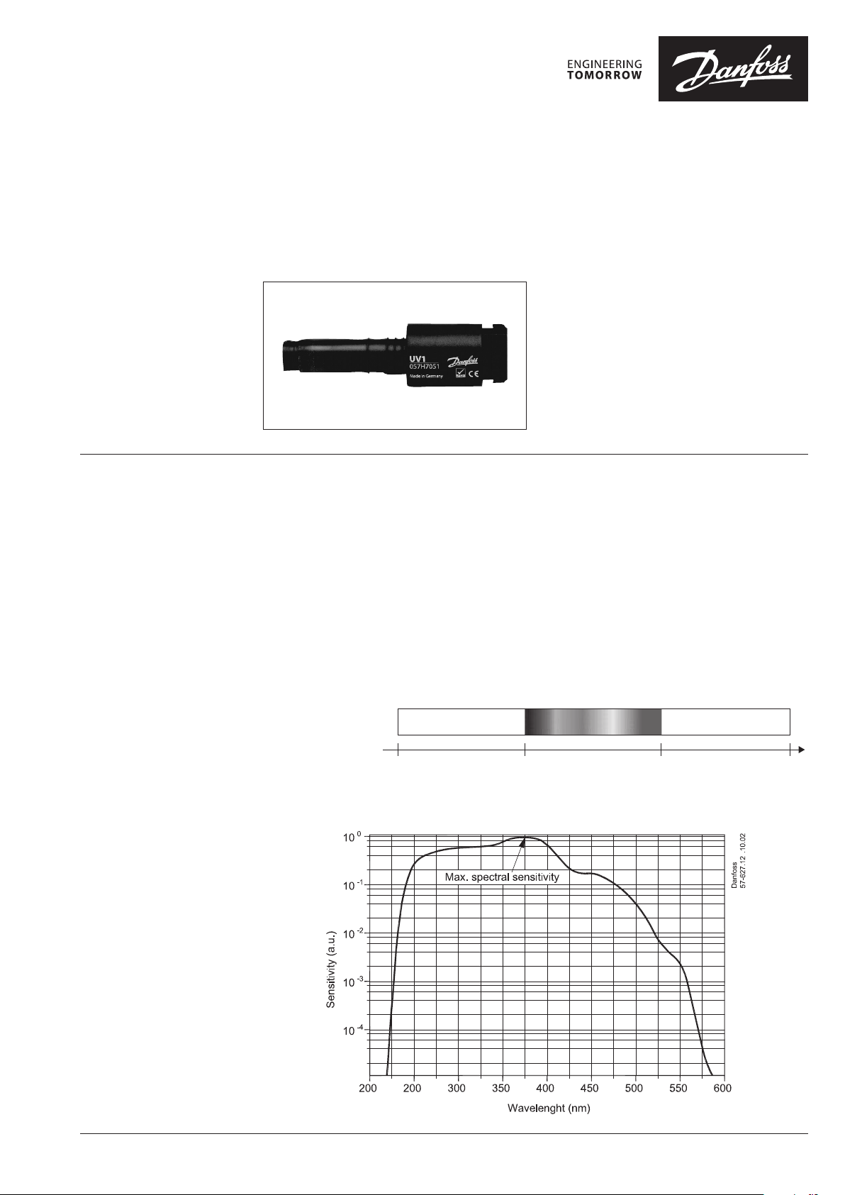
Light rays are sent at different wavelengths. The
light that the human eye can see lies in the range
of 380 to 760 nm and is called visible light.
In the blue flame oil burner the flame’s visible
light is very dim and therefore cannot be
detected by the LD/LDS sensor series, which is
built on the photoresistance principle.
In the case of UV sensors, the flame’s ultraviolet
light is used instead, which is detected by a UV
diode. In the sensors, the sensor signal is
converted by an amplifier circuit into a signal that
the control can use.
Ultraviolet light Visible light Infrared light
Danfoss UV sensors are used to detect the flame
in blue flame oil burners. They are intended for
use together with Danfoss controls in the OBC 80
and BHO 70 series.
The UV sensors meet the requirements of the
EN230:2005 standard and also meets the
requirements of the RoHS and WEEE Directives.
To ensure unambiguous detection of the
ultraviolet light, it is first transmitted through a
lens that focusses the light rays onto the surface
of the UV diode, and then through a filter that
reduces the sensitivity to a desired wavelength
range.
Danfoss UV sensors have max. sensitivity at 375
nm, which is apparent from the logarithmic
diagram, where sensitivity at 375 nm is given to
100%.
Wavelength
© Danfoss | 2019.07 VD.AU.A3.02 | 1
Page 2
Data sheet Ultraviolet Flame Sensor UV
12
Electrical connection
Mounting
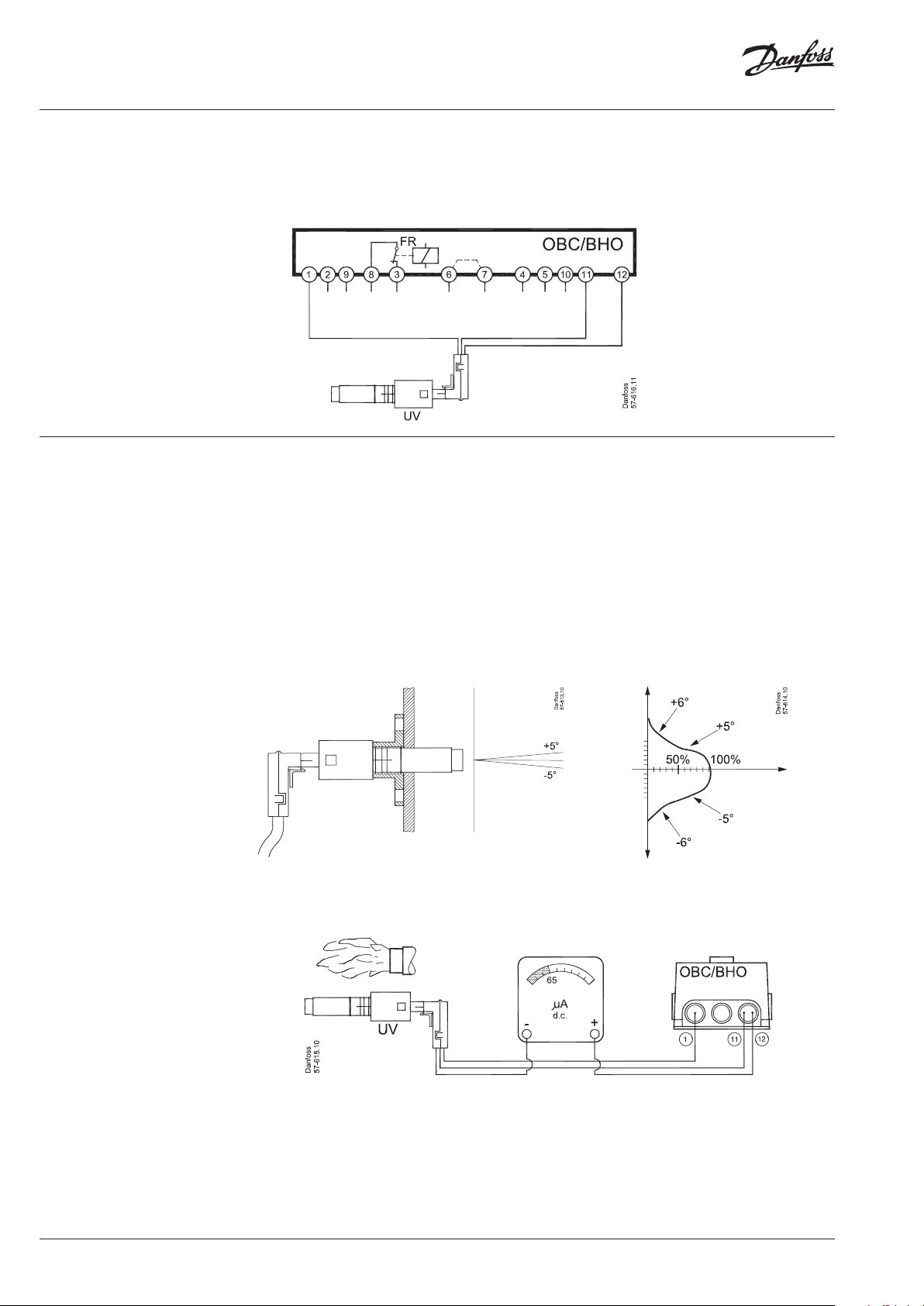
The UV sensors are connected to Danfoss
controls in the OBC 80 and BHO 70 series as
shown in the diagram.
The UV sensors are designed to be very directional to limit the influence of other light sources,
primarily the ignition spark that emits UV light.
The sensors must be installed so that they are not
affected by light from the ignition spark and, at
the same time, so that the best possible input
from the flame is achieved.
It is very important that the mounting flange or
piping used has the UV sensor fixed in the correct
position.
Note that the blue wire must be connected to
terminal 11 and not to the common 0 on terminal
2 or the appertaining auxiliary terminals in the
base section.
3
The UV sensors’ sensitivity is shown as a function
of the angle deviation in Fig. 1 and 2.
If a sufficient signal is not achieved, we recommend selecting a UV sensor of higher sensitivity.
To determine the quality of the signal, use the
measurement setup below.
If there is no flame/darkness, the value should be
≤ 5 µA and when there is a flame/light it should
be ≥65 µA.
1. Brown
2. Blue
3. Black
Fig. 1 Fig. 2
Fig. 3
2 | VD.AU.A3.02 © Danfoss | 2019.07
Page 3
Data sheet Ultraviolet Flame Sensor UV
Technical Data
Ordering
Mains connection 230 V, 50/60 Hz, 0.3 VA
Enclosure IP 40
Signal output max. 100 µA
Recommended min. signal output 65 µA
Signal for no light max. 5 µA
Ambient temperature
Weight 23 g
Wiring OBC 80/
BHO 70 series
Product Code no.
UV1 – Normal sensitivity 057H7051
Flange 057H7061
300 mm cable 057H1040
400 mm cable 057H1041
500 mm cable 057H1042
Operation -20 - +70 °C, short time operation up to 75 °C
Transp ort -30 - +70 °C
Brown wire, 230 V mains terminal 1
Blue wire, neutral terminal 11
Black wire, signal terminal 12
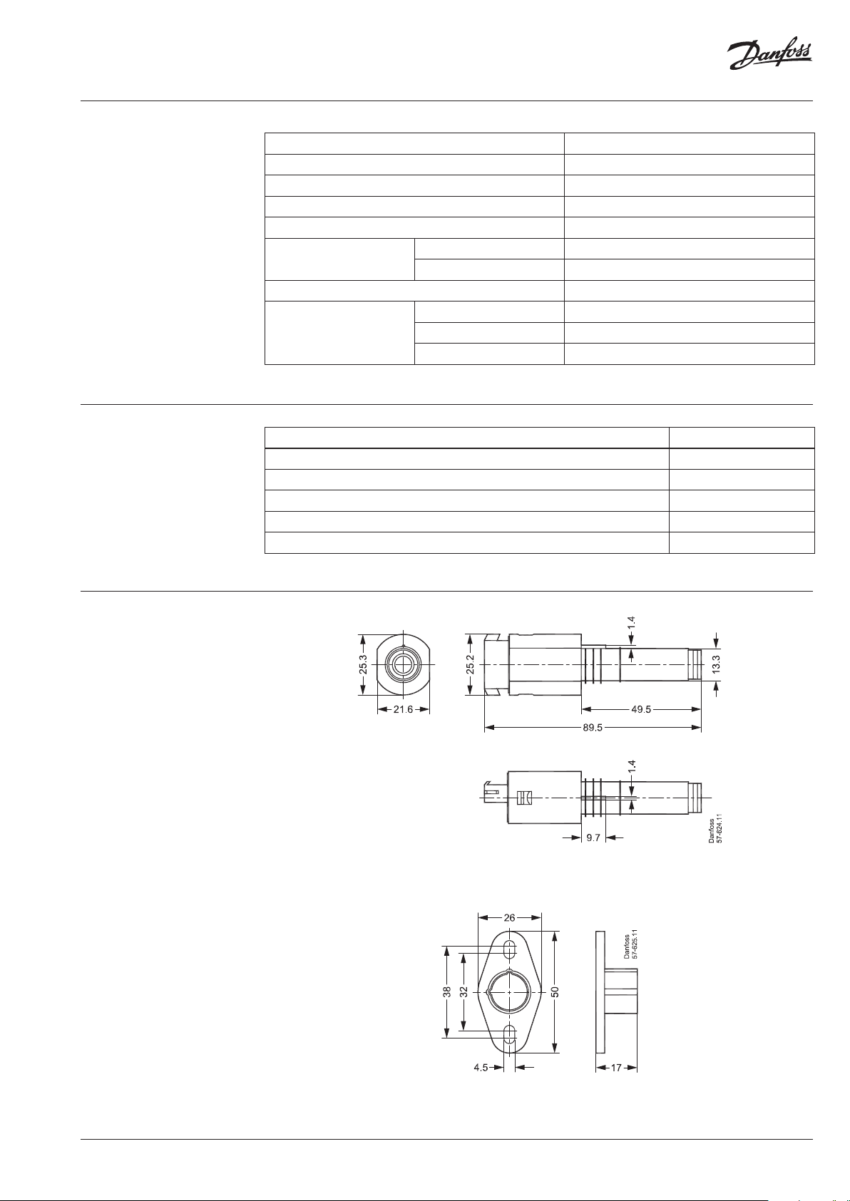
Dimensions
UV sensor
Flange
VD.AU.A3.02 | 3© Danfoss | 2019.07
Page 4

Danfos
produc
Al
Danfoss A/S
Heating Segment • heating
Data sheet Ultraviolet Flame Sensor UV
Additional documentation on burner components is available on http://heating.danfoss.com/
.danfoss.com • +45 7488 2222 • E-Mail: heating@danfoss.com
s can accept no responsibility for possible errors in catalogues, brochures and o ther printed material. Danfoss reserves the right to alter its products w ithout notice. This also applies to
ts already on order provided that such alterations can be m ade without subsequential changes being necessary in specications already agreed.
l trademarks in this material are p roperty of the respective companies. Danfoss and all D anfoss logotypes are trademarks of Danfoss A/S. All rights reserve d.
© Danfoss | DHS-SDBT | 2019.074 | VD.AU.A3.02
 Loading...