

Page 1

Data sheet
Balancing valves
USV-S
Application / Description
USV-S
USV-S valves are to be used in radiator heating
systems to limit the flow in risers or horizontal
loops.
USV-S valves are designed for manual hydronic
balancing of heating and cooling systems.
USV-S (black knob) is used to limit the flow
in heating or cooling installation or can work
separately as manual balancing valves for flow
limitation.
USV-S is compact valves in which the operating
elements and connections are placed within
an arc of 90°, so that in spite of small valve
dimensions, access for installation and operation
is optimal. Insulation caps for temperature up to
80 oC or 120 oC are available as accessory.
USV-S is supplied in a set-pack with internal
thread.
DEN-SMT/SI
USV-S in radiator application - vertical riser
USV-S can also be used in floor heating systems.
To limit the flow, every manifold with constant
flow should be used together with USV-S valves.
USV-S in oor heating systems
VD.C 1.N1.02 © Danfoss 06/2015
USV-S in radiator application - horizontal loop
1
Page 2

Data sheet Balancing valves USV-S
Application / Description
(continued)
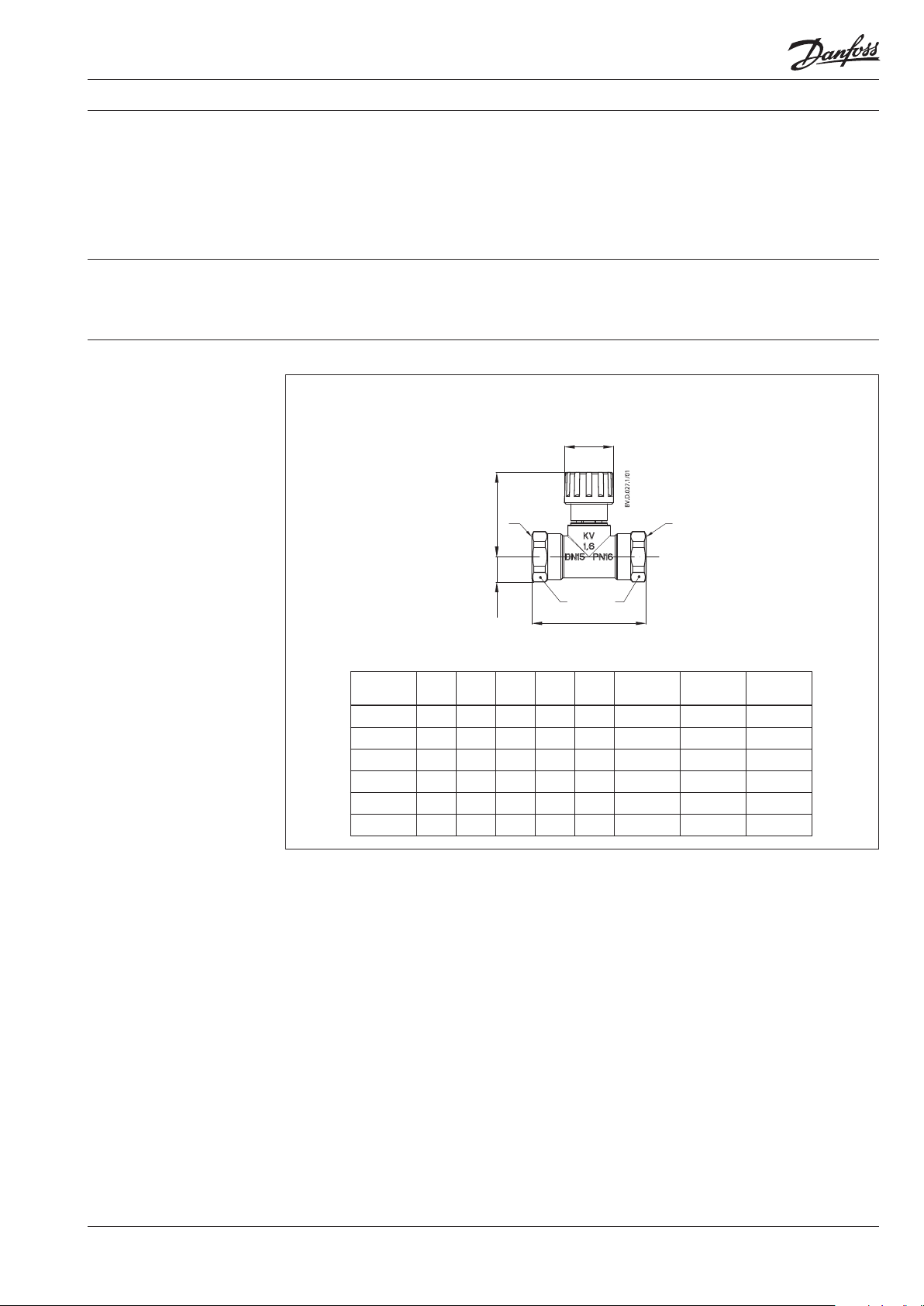
Ordering
The USV-S valves are to be used in systems with
fan coils to limit the ow in order to provide
ecient heat distribution.
USV-S valve
k
Int. thread
Typ e DN
VS
[m3/h]
15 1,6 Rp ½
20 2,5 Rp ¾
25 4 Rp 1
32 6,3 Rp 1¼
40 10 Rp 1½
50 16 Rp 2
USV-S in cooling systems
ISO 7/1
Code No.
003Z2231
003Z2232
003Z2233
003Z2234
003Z2235
003Z2236
Accessories and spare parts
Typ e Comments/connection Code No.
Insulation cap
up to 80 °C DN 15 003L8165
DN 20 003L8166
DN 25 003L8167
DN 32 0 03L8168
DN 40 003L8169
DN 50 003L8164
up to 120 ° C DN 15 003L8170
DN 20 003 L8171
DN 25 00 3L8172
DN 32 003L 8173
DN 40 00 3L 8139
DN 50 00 3L 8138
2
VD.C1.N1.02 © Danfoss 06/2015
DEN-SMT/SI
Page 3

Data sheet Balancing valves USV-S
S
E
B
C
P
.A
L
L
E
N
K
E
Y
.
00
1
.0
1
Technical data
Design
1. Shut- of f knob
2. Shut-off spindle
3. Setting spindle
4. Scale disc
5. O-rings
6. Valve cone
7. Valve body
Max. working pressure ........................................ 16 bar
Test pressure ...........................................................25 bar
Max. dierential pressure across
the valve (USV-S) ............................. 1,5 bar (150 kPa)
Flow temperature ...................... -20 to 120 °C
DN
S
S
O
F
N
A
D
15 2,5
20 3
25 4
32 5
40 5
Fig. 8 USV-S
USV-S incorporates a double cone (3.6) able to
give maximum stroke limitation, thus achieving
ow limitation. It also incorporates shut o
function.
Use the following procedure to limit the ow:
• turn the valve knob ① fully counter clockwise
to open the valve. The mark on the knob will
now be opposite »0« on the scale ④.
• turn the valve knob ① clockwise to the
required setting (e.g. for setting 2.2 the knob
must be rotated two full turns and then
forward to »2« on the scale.
• hold the knob ① to keep the setting (e.g. 2.2)
and using a hexagon socket key turn the
spindle ③ fully counter clockwise (until a stop
can be felt).
Material of parts in contact with water:
Valve body, spindle, etc. ....................................... Brass
Cone ................................................................... DZR Brass
Diaphragm and O-rings ...................................... EPDM
Spring ........................................................ Stainless steel
Port A Port B
• turn the valve knob ① fully counter clockwise
so that the mark on the knob is opposite »0«
on the scale ④. The valve is now open as
many turns from the closed position (2.2) as
indicated by the convertion from required
flow.
• to annul the setting, turn the hexagon socket
key fully clockwise (until a stop can be felt).
Remember, at the same time the knob must be
held on its »0« setting.
DEN-SMT/SI
VD.C1.N1.02 © Danfoss 06/2015
3
Page 4
Data sheet Balancing valves USV-S
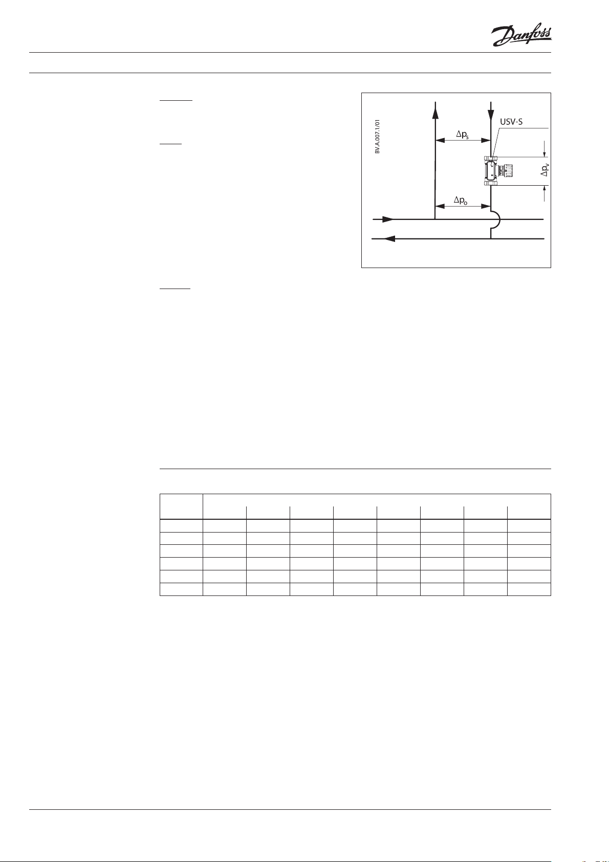
Sizing
Required:
A. Correct valve size USV-S
B. Correct USV-S presetting
Given:
1. Required max. flow in the riser
Q = 0,80 [m3/h]
2. Pressure drop across riser
Δps = 15 [kPa]
3. Available pump pressure
Δpo = 35 [kPa]
4. Connection pipe: DN 25
Solution:
A) USV-S DN20 is selected (same size as
connection pipe).
A straight line conecting this point and
Q = 0,80 [m3/h] intersects the differential
pressure bar at Δpv (USV-S) = 10 [kPa].
Δpo = Δps + Δpv (USV-S)
B) Correct valve size and presetting of USV-S:
The differential pressure across USV-S can be
calculated as follows:
Δpv (USV-S) = Δpo – Δp
s
Δpv = 35 [kPa] – 15 [kPa]
The example selects USV-S DN 20. Presetting
is read from the sizing diagram (page 5) by
taking a straight line from from max. flow
Q = 0,80 [m3/h] to the differential pressure Δpv
(USV-S)= 20 [kPa] and to the intersection with
kV-axis at kV = 1,8 [m3/h].
Draw a horizontal line from this point to the
adjustment curve of the chosen valve
(DN 20). Starting from closed valve, the
presetting of 1,6 turns is required.
kV-values [m3/h] for various presettings:
Size
0,2 0,5 1,0 1,5 2,0 2,5 3,0 3,2
Number of turns
DN 15 0,2 0,4 0,8 1,1 1, 3 1,5 1,6 1,6
DN 20 0,3 0,7 1,3 1,7 2,0 2,3 2,5 2,5
DN 25 0,4 1,1 1,9 2,7 3,3 3,6 3,9 4,0
DN 32 0,7 1,7 3,1 4,3 5,2 5,7 6 ,1 6,3
DN 40 0,9 2,1 4,2 5,9 7,4 8,7 9,7 10,0
DN 50 1,7 4,1 7,6 10,5 12, 7 14,0 15, 2 16,0
4
VD.C1.N1.02 © Danfoss 06/2015
DEN-SMT/SI
Page 5
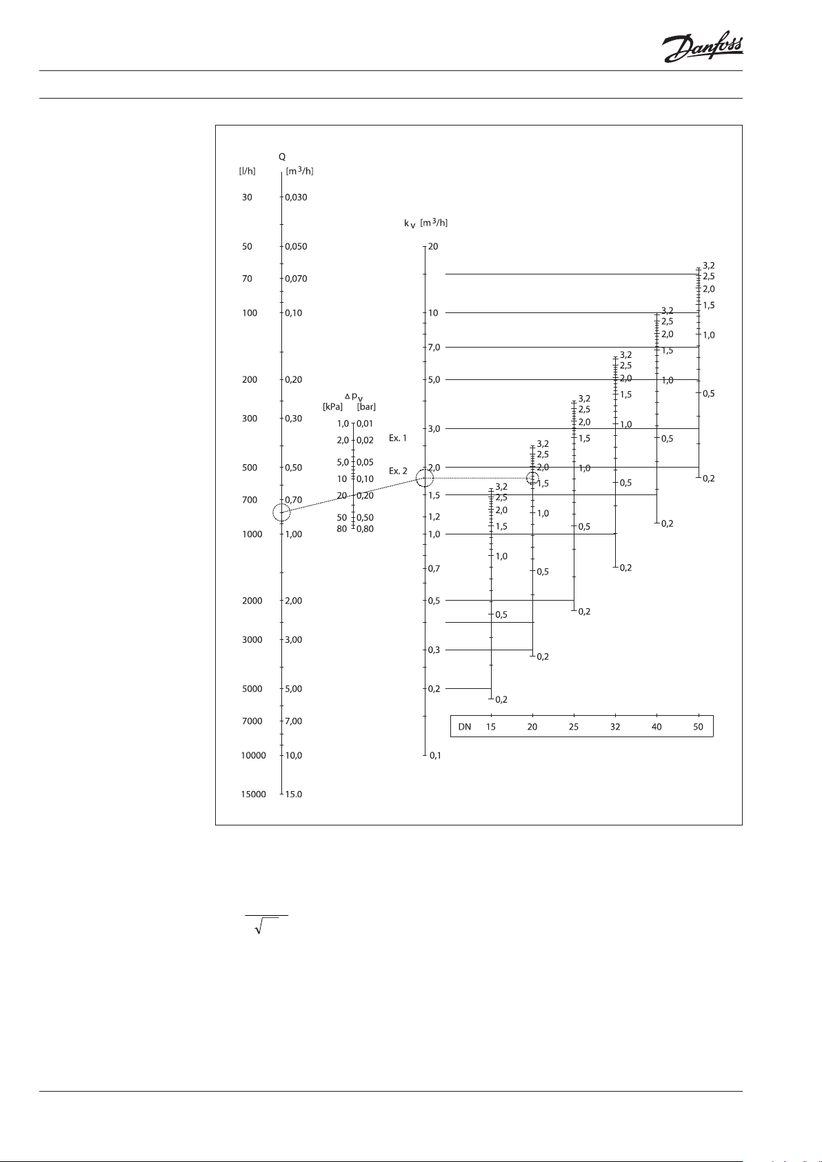
Q x1 0
Data sheet Balancing valves USV-S
Sizing (continued)
A straight line connecting the bars of flow,
differential pressure and kV value shows the
relationship between these three variables.
k
=
v
p
Δ
A horizontal line from the intersection with the
kV bar shows the presetting value for each valve
size.
Q [m3/h]
Δp [kPa]
5
VD.C1.N1.02 © Danfoss 06/2015
DEN-SMT/SI
Page 6
Data sheet Balancing valves USV-S
Installation
Pressure testing
Dimensions
USV-S should be instaled in the ow or return
pipe. The direction of the ow must follow the
direction of the arrow on the valve body.
Small installation dimensions enable easy
installation and shut-o of the system.
Max. test pressure ............................................... 25 bar
1
a a
H
2
H
USV-S can be installed in any positions if
installation instructions are being observed. It is
recommended that a lter i.e. Danfoss Typ FV is
installed in the supply pipe.
D
1
S S
L
1
USV-S
L
H
H
1
DN
[mm]
[mm]
1
[mm]
15 65 48 15 28 27 Rp ½ G ¾ A 0, 31
20 75 60 18 35 32 Rp ¾ G 1 A 0,4
25 85 75 23 45 41 Rp 1 G 1¼ A 0,67
32 95 95 29 55 50 Rp 1¼ G 1½ A 1,1
40 100 100 31 55 55 Rp 1½ G 1¾ A 1,22
50 130 10 6 38 55 67 Rp 2 G 2¼ A 2
D
2
1
[mm]S[mm]aIS O 7/1bISO 228/1
Weight
[kg]
DEN-SMT/SI
VD.C1.N1.02 © Danfoss 06/2015
6
Page 7
Data sheet Balancing valves USV-S
7
VD.C1.N1.02 © Danfoss 06/2015
DEN-SMT/SI
Page 8

Data sheet Balancing valves USV-S
8
VD.C1.N1.02
Produce d by Danfoss A/S © 06/2 015
 Loading...